document release and change form - hanford.gov · document release and change form prepared for the...
TRANSCRIPT

1 SPF-001 (Rev.D1)
DOCUMENT RELEASE AND CHANGE FORMPrepared For the U.S. Department of Energy, Assistant Secretary for Environmental ManagementBy Washington River Protection Solutions, LLC., PO Box 850, Richland, WA 99352Contractor For U.S. Department of Energy, Office of River Protection, under Contract DE-AC27-08RV14800
TRADEMARK DISCLAIMER: Reference herein to any specific commercial product, process, or service by trade name, trademark, manufacturer, or otherwise, does not necessarily constitute or imply its endorsement, recommendation, or favoring by the United States government or any agency thereof or its contractors or subcontractors. Printed in the United States of America.
Release Stamp
1. Doc No: RPP-SPEC-61096 Rev. 00
2. Title:Filter Housing General Equipment Procurement Specification
3. Project Number: ☒ N/A 4. Design Verification Required:☐ Yes ☒ No
5. USQ Number: ☒ N/AN/A-9
6. PrHA Number Rev. ☒ N/A
Clearance Review Restriction Type:public
7. Approvals
Title Name Signature DateClearance Review AARDAL, JANIS D AARDAL, JANIS D 09/20/2017Design Authority KHABIR, SHAROK KHABIR, SHAROK 09/19/2017Checker HENDRICKSON, DOUG W HENDRICKSON, DOUG W 09/18/2017Document Control Approval PORTER, MARY PORTER, MARY 09/20/2017Originator GROVES, CHASE C GROVES, CHASE C 09/19/2017Other Approver MACKEY, TOM MACKEY, TOM 09/14/2017Other Approver HENDRICKSON, MICHELLE L HENDRICKSON, MICHELLE L 09/19/2017Quality Assurance VERDERBER, JOHN J VERDERBER, JOHN J 09/12/2017Responsible Engineer GROVES, CHASE C GROVES, CHASE C 09/19/2017Responsible Engineering Manager BADER, KENT R BADER, KENT R 09/19/2017
8. Description of Change and Justification
Initial Release
9. TBDs or Holds ☒ N/A
10. Related Structures, Systems, and Components
a. Related Building/Facilities ☒ N/A b. Related Systems ☒ N/A c. Related Equipment ID Nos. (EIN) ☒ N/A
11. Impacted Documents – Engineering ☒ N/A
Document Number Rev. Title
12. Impacted Documents (Outside SPF):
N/A
13. Related Documents ☐ N/A
Document Number Rev. TitleRPP-SPEC-61094 00 General Equipment Procurement Specification for a Moisture SeparatorRPP-SPEC-61095 00 General Equipment Procurement Specification for a Fan
14. Distribution
Name OrganizationBADER, KENT R MISSION ANALYSIS ENGINEERINGFARRIS, TROY R PROJECT ENGINEERING (DA)GENONI, MICHAEL R PROCUREMENT ENGINEERINGHALL, MARK DESIGN SERVICESHENDRICKSON, DOUG W MISSION ANALYSIS ENGINEERINGHENDRICKSON, MICHELLE L MISSION ANALYSIS ENGINEERINGIRWIN, JOHN DESIGN SERVICESKHABIR, SHAROK ENGRNG PROGRAMS & STANDARDSMACKEY, TOM ENGRNG PROGRAMS & STANDARDSSCHOEPFLIN, DANNY E MECHANICAL & HVAC ENGINEERINGSHREEVE, BRYCE DESIGN SERVICESVERDERBER, JOHN J QA PROGRAMS & ASSESSMENTSZINTER, DONALD D PROCUREMENT ENGINEERING
RPP-SPEC-61096 Rev.00 9/20/2017 - 6:51 AM 1 of 100
Sep 20, 2017DATE:

RPP-SPEC-61096 Rev. 0
A-6002-767 (REV. 3)
Filter Housing General Equipment Procurement Specification
Chase Groves
Washington River Protection Solutions, LLCRichland, WA 99352U.S. Department of Energy Contract DE-AC27-08RV14800
EDT/ECN: DRCF UC: N/A
Cost Center: 2KL00 Charge Code: 202856
B&R Code: N/A Total Pages: 100
Key Words:
General Equipment Procurement Specification, Procurement, Requirements, Exhaust Skid, Filter Housing, HEPA, Ventilation, Exhaust Train
Abstract:
This General Equipment Procurement Specification (Specification) provides technical requirements for the design, fabrication, testing, quality oversight, packaging, transportation, and delivery of primary ventilation filter housing components.
_________________________________________________________________________________
TRADEMARK DISCLAIMER. Reference herein to any specific commercial product, process, or service by trade name, trademark, manufacturer, or otherwise, does not necessarily constitute or imply its endorsement, recommendation, or favoring by the United States Government or any agency thereof or its contractors or subcontractors.
Release Approval Date Release Stamp
Approved For Public Release
RPP-SPEC-61096 Rev.00 9/20/2017 - 6:51 AM 2 of 100
By Janis Aardal at 6:55 am, Sep 20, 2017
Sep 20, 2017DATE:

Filter Housing General Equipment Procurement Specification
Prepared by
Chase GrovesWashington River Protection Solutions, LLC
Date PublishedSeptember 2017
Prepared for the U.S. Department of EnergyOffice of River Protection
Contract No. DE-AC27-08RV14800
Approved for Public Release;
Further Dissemination Unlimited
RPP-SPEC-61096 Rev.00 9/20/2017 - 6:51 AM 3 of 100

RPP-SPEC-61096 Rev. 0
ii
TABLE OF CONTENTS
1.0 SCOPE ................................................................................................................................ 1
1.1 DESCRIPTION............................................................................................................... 1
1.2 DOCUMENT OVERVIEW............................................................................................ 1
1.3 BACKGROUND ............................................................................................................ 2
1.4 TRADEMARK DISCLAIMER...................................................................................... 2
1.5 DEFINITIONS................................................................................................................ 2
1.6 ABBREVIATIONS, ACRONYMS, AND UNITS ........................................................ 3
2.0 APPLICABLE DOCUMENTS .......................................................................................... 6
2.1 GOVERNMENT DOCUMENTS................................................................................... 6
2.2 NON-GOVERNMENT DOCUMENTS......................................................................... 7
2.3 NON-GOVERNMENT / NON-CODE OF RECORD DOCUMENTS ....................... 10
2.4 HIERARCHY OF CODE ............................................................................................. 10
3.0 SYSTEM CHARACTERISTICS AND REQUIREMENTS............................................ 12
3.1 SYSTEM FUNCTIONS AND FUNCTION PERFORMANCE REQUIREMENTS.. 12
3.2 SSC INTERFACES ...................................................................................................... 12
3.2.1 Internal Interfaces ................................................................................................... 13
3.2.2 External Interfaces .................................................................................................. 15
3.3 SSC CHARACTERISTICS.......................................................................................... 17
3.3.1 Functional Characteristics....................................................................................... 17
3.3.2 Physical Characteristics .......................................................................................... 18
3.4 DESIGN AND CONSTRUCTION REQUIREMENTS .............................................. 21
3.4.1 Safety ...................................................................................................................... 21
3.4.2 Major VFH Components......................................................................................... 22
3.4.3 Fire Screens............................................................................................................. 24
3.4.4 HEPA and Prefilter Housing Sections .................................................................... 24
3.4.5 Transition Section ................................................................................................... 29
3.4.6 Dampers .................................................................................................................. 30
3.4.7 Damper Actuators ................................................................................................... 30
3.4.8 Heater Section......................................................................................................... 30
RPP-SPEC-61096 Rev.00 9/20/2017 - 6:51 AM 4 of 100

RPP-SPEC-61096 Rev. 0
iii
3.4.9 Prefilter Section ...................................................................................................... 31
3.4.10 Test Sections ........................................................................................................... 31
3.4.11 HEPA Filter Housing Sections ............................................................................... 32
3.4.12 Related Major VFH Component Requirements...................................................... 34
3.4.13 Materials ................................................................................................................. 35
3.4.14 Lifting ..................................................................................................................... 39
3.4.15 Electrical and Motor Requirements ........................................................................ 40
3.4.16 Security ................................................................................................................... 41
3.4.17 Deterioration and Protection ................................................................................... 41
3.4.18 Decontamination and Decommissioning ................................................................ 42
3.4.19 Pollution Prevention and Waste Minimization ....................................................... 42
3.4.20 Electromagnetic Radiation...................................................................................... 42
3.4.21 Nameplates and Product Marking........................................................................... 42
3.4.22 Personnel And Training .......................................................................................... 43
3.4.23 Human Factors Engineering ................................................................................... 43
3.5 SYSTEM RELIABILITY, AVAILABILITY, MAINTAINABILITY, AND INSPECTABILITY .................................................................................................................. 43
3.5.1 Reliability................................................................................................................ 43
3.5.2 Availability ............................................................................................................. 44
3.5.3 Maintainability........................................................................................................ 44
3.5.4 Accessibility & Inspectability................................................................................. 45
4.0 FABRICATION REQUIREMENTS................................................................................ 46
4.1 WELDING REQUIREMENTS.................................................................................... 46
4.1.1 Structural Welding .................................................................................................. 46
4.1.2 Weld Materials........................................................................................................ 47
4.1.3 Welding Procedures and Qualifications.................................................................. 47
4.1.4 Weld Inspection Requirements ............................................................................... 47
4.1.5 Additional Welding Requirements ......................................................................... 49
4.1.6 Workmanship.......................................................................................................... 49
4.2 CLEANLINESS............................................................................................................ 49
5.0 PRODUCTION INSPECTION AND TESTING REQUIREMENTS ............................. 51
5.1 QUALIFICATION TESTS........................................................................................... 51
RPP-SPEC-61096 Rev.00 9/20/2017 - 6:51 AM 5 of 100

RPP-SPEC-61096 Rev. 0
iv
5.1.1 Functional Test........................................................................................................ 51
5.1.2 VFH Air Flow Distribution Test............................................................................. 52
5.1.3 VFH Performance Test ........................................................................................... 52
5.1.4 Structural Capability Test ....................................................................................... 53
5.1.5 Factory Acceptance Testing.................................................................................... 53
5.1.6 Air-Aerosol Mixing Uniformity Tests .................................................................... 54
5.1.7 Sampling Manifold Tests........................................................................................ 54
5.1.8 Air Conditioning/Air Handling Unit Tests ............................................................. 54
5.1.9 Materials Testing Requirements ............................................................................. 54
5.2 PRODUCTION INSPECTION .................................................................................... 54
5.2.1 Dimensional Inspection .......................................................................................... 55
5.2.2 Welding Inspection ................................................................................................. 55
5.2.3 VFH Inspection Requirements................................................................................ 55
6.0 DELIVERY, STORAGE, AND HANDLING ................................................................. 56
6.1 DELIVERY, STORAGE & LOAD HANDLING........................................................ 56
6.1.1 General.................................................................................................................... 56
6.1.2 Transportability....................................................................................................... 56
6.1.3 Packaging................................................................................................................ 57
6.1.4 Handling.................................................................................................................. 60
6.1.5 Storage .................................................................................................................... 62
6.1.6 Delivery................................................................................................................... 66
6.1.7 Marking for Shipment............................................................................................. 66
6.2 QUALITY ASSURANCE............................................................................................ 67
6.3 SITE CONDITIONS..................................................................................................... 68
7.0 PROJECT MANAGEMENT............................................................................................ 69
7.1 WORK PLAN............................................................................................................... 69
7.2 SUBMITTALS ............................................................................................................. 69
7.2.1 Submittals Required With Proposal........................................................................ 69
7.2.2 Submittals Required After Receipt of Order .......................................................... 69
7.2.3 Submittals Required Prior to Fabrication ............................................................... 70
7.2.4 Submittals Required for Contract Completion ....................................................... 70
7.2.5 Request For Information ......................................................................................... 72
RPP-SPEC-61096 Rev.00 9/20/2017 - 6:51 AM 6 of 100

RPP-SPEC-61096 Rev. 0
v
7.3 QUALITY ASSURANCE PROGRAM ....................................................................... 72
7.3.1 Non-Conformance Reports ..................................................................................... 72
7.3.2 Inspection/Examination .......................................................................................... 72
7.3.3 Suspect/Counterfeit Items....................................................................................... 73
7.3.4 Certificate of Conformance..................................................................................... 73
8.0 REFERENCES ................................................................................................................. 74
ATTACHMENTS
ATTACHMENT A: EQUIPMENT DATA SHEETS………………………………………….A-1
ATTACHMENT A.1: VENTILATION FILTER HOUSING………………………………....A-1
ATTACHMENT A.2: HEATER………………………………………………………..……...A-7
ATTACHMENT A.3: PREFILTER……………………………………………….………….A-12
ATTACHMENT A.4: HEPA FILTER………………………………………………...……...A-16
LIST OF TABLES
Table 2-1. Government Documents................................................................................................ 6Table 2-2. Non-Government Documents........................................................................................ 7Table 2-3. Non-Government Non-Code of Record Documents (BUYER Supplied Documents)10
RPP-SPEC-61096 Rev.00 9/20/2017 - 6:51 AM 7 of 100

RPP-SPEC-61096 Rev. 0
1
1.0 SCOPE
This General Equipment Procurement Specification (Specification) establishes the functions, performance requirements, interfaces, and design requirements for the design, fabrication, testing, quality oversight, packaging, transportation, and delivery of the primary system’s Ventilation Filter Housings (VFH). Specific VFH design criteria and performance requirements are found in the accompanying Equipment Data Sheet (EDS). An EDS may be revised without revising this Specification given appropriate project needs.
1.1 DESCRIPTION
Washington River Protection Solutions, LLC (WRPS), is the U.S. Department of Energy, (DOE), Office of River Protection Tank Operations Contract (or) (TOC). WRPS is contracted to provide safe, compliant, cost-effective, and energy-efficient services to further the DOE-Office of River Protection Project (RPP) Mission. In order to safely complete the RPP Mission, various permanent or temporary systems and associated components are required.
This Specification identifies and communicates the common inputs, requirements, and criteria for the design and procurement of a permanent or temporary ventilation filter housing. The function of the VFH is to configure containment air filtration housing components of a ventilation system and provide appurtenances for testing, maintenance, and replacement of the treatment train components. Tank farm ventilation systems must be designed to manage radioactively contaminated air and provide treatment of regulated contaminants.
Specific VFH inputs and requirements for design and procurement are exemplified in Attachment A, Equipment Datasheets. This Specification must be used in conjunction with an EDS. The EDSs are populated based on project specific needs identified in the project Function Criteria Document, or Level 2 Specification. All references to the EDSs in this document will be to the issued EDSs associated with the VFH components specified by the project. Code of Record (COR) supporting design of the VFH shall be extracted from the modification traveler specific to the project for which the VFH is being procured and shall delineate the appropriate design criteria within the EDSs.
TOC ventilation system design for General Service use follows ASME AG-1 guidelines implicitly along with Nuclear Facility systems. Additional information may be documented in the associated EDSs, System Specifications, Statements of Work, Material Requests (MR), or notes attached to a MR.
1.2 DOCUMENT OVERVIEW
This Specification is a “design-build” Specification, delineating the required functions and requirements to which the SELLER shall adhere in providing the finished product/services to the BUYER. Major filter housing components and are listed in Section 3.4.2. Where specific
RPP-SPEC-61096 Rev.00 9/20/2017 - 6:51 AM 8 of 100

RPP-SPEC-61096 Rev. 0
2
make and model of equipment and/or systems is called out in this Specification or EDS, BUYER-approved equivalents will be considered.
Specific to this document, the requirements and definitions of Section 1.5 are applicable.
The equipment being procured via this Specification shall interface with BUYER-provided equipment and systems in accordance with Section 3.2.
1.3 BACKGROUND
The Hanford Site located in Washington State contains the largest quantity of legacy tank waste in the DOE complex. Most of these wastes, resulting from the processing operations of defense nuclear materials, are stored in 177 underground storage tanks. The tanks contain an estimated 56 million gallons of hazardous and radioactive liquids, sludge, and salt cake with approximately 175 million curies of radioactivity. These tanks are located on the Central Plateau of the Hanford Site in 200 East and 200 West Areas. Storage and processing facilities associated with these tank wastes require treated ventilation systems. This Specification is prepared to detail requirements associated with the ventilation filter housing.
1.4 TRADEMARK DISCLAIMER
Reference herein to any specific commercial product, process, or service by trade name, trademark, SELLER, or otherwise, does not necessarily constitute or imply endorsement, recommendation, or favoring by the United States Government or any agency thereof or its contractors or subcontractors.
1.5 DEFINITIONS
BUYER. The word “BUYER” used throughout this document refers to the TOC contractor
responsible for managing the design, procurement, and construction of the filter housing project.
Nonconformance. A deficiency in component characteristic, as defined in BUYER approved
drawings and documents.
Procurement Clauses. Procurement Quality Clauses are to be used for the acquisition of items
and services. The clauses establish contractual obligations for quality program systems,
identification traceability, document submittals, testing, reporting, qualification, special process
controls, inspections, etc.
RPP-SPEC-61096 Rev.00 9/20/2017 - 6:51 AM 9 of 100

RPP-SPEC-61096 Rev. 0
3
Product Data. Printed information including, but not limited to, catalog cuts, color charts,
illustrations, diagrams, templates, performance curves, brochures, and other forms of Product
literature.
Rated Load. The maximum load that can be lifted by the device.
SELLER. The word “SELLER” used throughout this document refers to the contracted fabricator, SELLER, or subcontractor performing work to the contract drawings, EDS, and technical specifications.
Shall/Must. Denotes project requirements, compliance is required.
Should. The word “should” denotes recommendation or expectation, compliance is expected. If a “should” recommendation cannot be satisfied, justification of an alternative design solution shall be submitted to the BUYER for approval.
Substitution. Any change or deviation from issued approved drawings, designs, methods, or contract terms and conditions. Changes in products, materials, equipment, methods of construction, and test criteria required by the Contract Documents proposed by the SELLER after award of the Contract are considered to be requests for substitution.
Will. The word “will” used throughout this document denotes a statement of fact.
WITNESS POINT. An inspection activity beyond which work shall not proceed until an inspector and/or BUYER is notified and (1) the inspection is performed and released, or (2) the inspection is deferred and can be completed at a later time, or (3) a written waiver is issued by the organization who established the witness point.
1.6 ABBREVIATIONS, ACRONYMS, AND UNITS
ABBREVIATIONS & ACRONYMS
AHU Air Handling Unit
AISC American Institute of Steel Construction
AMCA Air Movement and Control Association
AO Analog Output
ASCE American Society of Civil Engineers
ASHRAE American Society of Heating, Refrigerating, and Air-Conditioning Engineers
ASME American Society of Mechanical Engineers
ASNT American Society for Non-Destructive Testing
ASTM American Society for Testing and Materials
AWS American Welding Society
B&PVC Boiler and Pressure Vessel Code
RPP-SPEC-61096 Rev.00 9/20/2017 - 6:51 AM 10 of 100

RPP-SPEC-61096 Rev. 0
4
ABBREVIATIONS & ACRONYMS
BTH Below-the-Hook
CFR Code of Federal Regulations
CMTR Certified Material Test Reports
COR Code of Record
DO Digital Output
DOE US Department of Energy
dP Differential Pressure
EDS Equipment Data Sheet
HEPA High-Efficiency Particulate Air
IESNA Illuminating Engineering Society of North America
I/O Input/Output
IBC International Building Code
MOP Maximum Operating Pressure
MR Material Request
NDE Non-Destructive Examination
NFPA National Fire Protection Association
NQA Nuclear Quality Assurance
PMI Positive Material Identification
PSSH Packaging, Storage, Shipping, and Load Handling
RFI Request for Information
RPP River Protection Project
SAE Society of Automotive Engineers
QA Quality Assurance
SSC Structures, Systems, and Components
TOC Tank Operations Contract(or)
UL Underwriters Laboratory
VDC Volts Direct Current
VFH Ventilation Filter Housing
WRPS Washington River Protection Solutions, LLC
RPP-SPEC-61096 Rev.00 9/20/2017 - 6:51 AM 11 of 100

RPP-SPEC-61096 Rev. 0
5
1 A separate units table is included in each Equipment Data Sheet
UNITS1
BTU British Thermal Units
°C Degrees Celsius
cfm Cubic Feet per Minute
deg. degrees
°F Degrees Fahrenheit
ft2 Square feet
g Gravity of Earth
hr hour
Hz hertz
in Hg Inches of Mercury
ksi Kilo pound per square inch
m meter
MPa Mega Pascals
mph Miles per hour
ppm Parts per million
scfm Standard Cubic Feet per Minute
V volts
wc Water Column
wg Water Gauge
RPP-SPEC-61096 Rev.00 9/20/2017 - 6:51 AM 12 of 100

RPP-SPEC-61096 Rev. 0
6
2.0 APPLICABLE DOCUMENTS
The following tables serve as the set of requirements that are used to design, construct, operate and decommission a nuclear facility or a mission critical, non-nuclear facility (or their structures, systems, and components [SSCs]) over its lifespan. When specifying requirements for procurement, the Design Authority/Subject Matter Expert shall ensure that the specific codes/standards and regulation references selected for the item’s design are included in the COR, according to TFC-ENG-DESIGN-C-57, “Development and Maintenance of Code of Record.”
The following documents may not be an all-inclusive list and considerations for the design for specific farms, facilities, and projects must be taken into consideration. In the event of a conflict between the documents referenced herein and the requirements of the EDS, the requirements of the EDS shall take precedence. Any deviation from these editions must be approved by the BUYER prior to fabrication.
2.1 GOVERNMENT DOCUMENTS
The following documents, of the exact issue shown in Table 2-1, form a part of this Specification to the extent specified herein and establish the Code of Record. Unless otherwise shown or noted, the latest edition and addenda are applicable.
Table 2-1. Government Documents
Document Number Title
Code of Federal Regulations (CFR)
10 CFR 830 “Nuclear Safety Management”
10 CFR 436 “Federal Energy Management and Planning Programs”
U.S. Department of Energy (DOE)
DOE O 420.1C “Facility Safety”
DOE-HDBK-1169 “Nuclear Air Cleaning Handbook”
DOE/RL-92-36 “Hanford Site Hoisting and Rigging Manual”
DOE-STD-1066 “Fire Protection”
DOE-STD-3020-2015 Specification for High Efficiency Particulate Air (HEPA) Filters used by DOE Contractors
Note: The following documents, identified in Table 2-1, Table 2-2, and Table 2-3 are an example and represent requirements identified as part of this specification. This example is not final and is subject to change with project needs. The project’s final COR will be listed
in appropriate documents, such as the Modification Traveler and specified in the EDS.
RPP-SPEC-61096 Rev.00 9/20/2017 - 6:51 AM 13 of 100

RPP-SPEC-61096 Rev. 0
7
Table 2-1. Government Documents
Document Number Title
Military Standard
MIL-STD-889B “Dissimilar Metals”
2.2 NON-GOVERNMENT DOCUMENTS
The following documents, of the exact issue shown, establish the Code of Record, or basis of design for the VFH. Unless otherwise shown or noted, the latest edition and addenda are applicable.
Table 2-2. Non-Government Documents
Document Number Title
Air-Conditioning, Heating, and Refrigeration Institute (AHRI)
AHRI 410-2001 Forced-Circulation Air Cooling and Air-Heating Coils
American Institute of Steel Construction (AISC)
AISC 325M “Steel Construction Manual”
AISC 360 “Specification for Structural Steel”
Air Movement and Control Association (AMCA)
AMCA 99-0401-86 “Classification for Spark Resistant Construction”
AMCA 511-10 “Certified Ratings Program Product Rating Manual for Air Control Devices”
AMCA Standard 500 D “Laboratory Methods of Testing Dampers for Rating”
American Society of Civil Engineers (ASCE)
ASCE 7-10 “Minimum Design Loads and Associated Criteria for Buildings and Other Structures”
American Society of Heating, Refrigerating, and Air-Conditioning Engineers (ASHRAE)
ASHRAE 62.1 “Ventilation for Acceptable Indoor Air Quality”
ASHRAE 52.2 “Method of Testing General Ventilation Air – Cleaning Devices for Removal Efficiency by Particle Size”
ASHRAE 90.1 “Energy Standard for Buildings Except Low-Rise Residential Buildings”
American Society of Mechanical Engineers (ASME)
ASME AG-1 “Code on Nuclear Air and Gas Treatment”
RPP-SPEC-61096 Rev.00 9/20/2017 - 6:51 AM 14 of 100

RPP-SPEC-61096 Rev. 0
8
Table 2-2. Non-Government Documents
Document Number Title
ASME Boiler and Pressure Vessel Code(B&PVC), Sect. II, Part A, B, C
“Materials: Part A - Ferrous Materials; Part B - Non-Ferrous Materials; Part C - Specifications for Welding Rods, Electrodes, and Filler Metals”
ASME B&PVC, Sect. IX
“Welding and Brazing Qualifications”
ASME B16.5 “Pipe Flanges and Flanged Fittings (NPS 1/2 through NPS 24 Metric/Inch Standard)”
ASME B18.2.1 “Square, Hex, Heavy Hex, and Askew Head Bolts And Hex, Heavy Hex, Hex Flange, Lobed Head, and Lag Screws (Inch Series)”
ASME B18.2.2 “Nuts for General Applications: Machine Screw Nuts, Hex, Square, Hex Flange, and Coupling Nuts (Inch Series)”
ASME B30.20 “Below-The-Hook Lifting Devices”
ASME B31.3 “Process Piping”
ASME BTH-1 “Design of Below-The-Hook (BTH) Lifting Devices”
ASME N509 “Nuclear Power Plant Air-Cleaning Units and Components”
ASME N511 “In Service Testing of Nuclear Air Treatment, Heating, Ventilating, and Air Conditioning Systems”
ASME Nuclear Quality Assurance (NQA)-1 (2008/2009A)
“Quality Assurance Requirements for Nuclear Facility Applications”
American Society for Nondestructive Testing (ASNT)
ASNT SNT-TC-1A “Personnel Qualification and Certification in Nondestructive Testing”
American Society for Testing and Materials (ASTM)
A193/A193M-16 “Standard Specification for Alloy-Steel and Stainless Steel Bolting for High Temperature or High Pressure service and Other Special Purpose Applications”
A194/A194M-16 “Standard Specification for Carbon Steel, Alloy Steel, and Stainless Steel Nuts for Bolts for High Pressure or High Temperature Service, or Both”
ASTM A240/A240-M “Standard Specification for Chromium and Chromium-Nickel Stainless Steel Plate, Sheet, and Strip for Pressure Vessels and for General Applications”
RPP-SPEC-61096 Rev.00 9/20/2017 - 6:51 AM 15 of 100

RPP-SPEC-61096 Rev. 0
9
Table 2-2. Non-Government Documents
Document Number Title
ASTM A307-14 “Standard Specification for Carbon Steel Bolts, Studs, and Threaded Rod 60000 PSI Tensile Strength”
ASTM A563-15 “Standard Specification for Carbon and Alloy Steel Nuts”
ASTM D1056-14 “Standard Specification for Flexible Cellular Materials – Sponge or Expanded Rubber”
ASTM F3125/F3125M “Standard Specification for High Strength Structural Bolts, Steel and Alloy Steel, Heat Treated, 120 ksi (830 MPa) and 150 ksi (1040 MPa) Minimum Tensile Strength, Inch and Metric Dimensions”
ASTM F436/F436M “Standard Specification for Hardened Steel Washers Inch and Metric Dimensions”
American Welding Society (AWS)
AWS B2.1/B2.1M-BMG
“Base Metal Grouping for Welding Procedure and Performance Qualification”
AWS D1.1/D1.1M “Structural Welding Code – Steel”
AWS D1.3/D1.3M “Structural Welding Code – Sheet Steel”
AWS D1.6/D1.6M “Structural Welding Code – Stainless Steel”
AWS D9.1/D9.1M “Sheet Metal Welding Code”
AWS QC1 “Standard for AWS Certification of Welding Inspectors”
Illuminating Engineering Society of North America (IESNA)
IESNA Handbook 10th
EditionLighting Handbook
International Code Council (IBC)
IBC 2015 International Building Code
National Fire Protection Association (NFPA)
NFPA 70 “National Electric Code”
NFPA 77 “Recommended Practice on Static Electricity”
NFPA 90A “Standard for the Installation of Air-Conditioning and Ventilating Systems”
Society of Automotive Engineers (SAE)
SAE J429 “Mechanical and Material Requirements for Externally Threaded Fasteners”
SAE J995 “Mechanical and Material Requirements for Steel Nuts”
RPP-SPEC-61096 Rev.00 9/20/2017 - 6:51 AM 16 of 100

RPP-SPEC-61096 Rev. 0
10
Table 2-2. Non-Government Documents
Document Number Title
Underwriters Laboratory (UL)
UL 900 “Standard for Air Filter Units”
2.3 NON-GOVERNMENT / NON-CODE OF RECORD DOCUMENTS
The SELLER shall draft a Request for Information (RFI) to inquire about specific Tank Operations Contract(or) (TOC) standards, procedures, and documents. The following documents are utilized or referenced by this Specification but are not considered COR. Unless otherwise shown or noted, the latest edition and addenda are applicable.
Table 2-3. Non-Government Non-Code of Record Documents (BUYER Supplied Documents)
Document Number Title
Washington River Protection Solutions, LLC (WRPS)
RPP-8360 “Lifting Attachment and Lifted Item Evaluation, A Hanford Tank Operating Contractor Process”
RPP-SPEC-60522 “General Procurement Specification for Standard Nuclear Grade HEPA Filters (For ASME AG-1, Section FC Compliant Filters)”
TFC-ENG-STD-02 “Environmental/Seasonal Requirements for TOC Systems, Structures, and Components”
TFC-ENG-STD-06 “Design Loads for Tank Farm Facilities”
TFC-ENG-STD-07 “Ventilation System Design Standard”
2.4 HIERARCHY OF CODE
Except in those instances where Washington State has been granted regulatory authority by the Federal Government, the hierarchical relationship among requirements identified in this Specification is as follows:
1. Federal requirements (e.g. Code of Federal Regulations)2. Washington State requirements (e.g. Washington Administrative Code)3. Local ordinances4. U.S. Department of Energy Orders and Standards5. National Consensus Codes and Standards6. Hanford Site-specific Codes and Standards
This hierarchy establishes the order of precedence of requirements levied in this Specification. In the event of a conflict between two requirements, the SELLER shall submit a RFI for
RPP-SPEC-61096 Rev.00 9/20/2017 - 6:51 AM 17 of 100

RPP-SPEC-61096 Rev. 0
11
clarifications prior to use. Design of the VFH shall be governed by the nationally recognized code ASME AG-1, “Code on Nuclear Air and Gas Treatment” to the extent invoked in this Specification.
RPP-SPEC-61096 Rev.00 9/20/2017 - 6:51 AM 18 of 100

RPP-SPEC-61096 Rev. 0
12
3.0 SYSTEM CHARACTERISTICS AND REQUIREMENTS
This section addresses the following component characteristics and requirements:
Functions and function performance requirements in Section 3.1 Interfaces and interface performance requirements in Section 3.2 SSC Characteristics in Section 3.3 Design and construction requirements in Section 3.4 Reliability, Availability, Maintainability, and Inspectability requirements in Section
3.5
The VFH is the portion of an air cleaning, air conditioning, or air handling assembly that encloses, and provides access to their respective components, and provides connections to adjacent ductwork, instrumentation, and ancillary systems (ASME AG-1, Section HA).
3.1 SYSTEM FUNCTIONS AND FUNCTION PERFORMANCE REQUIREMENTS
General function performance requirements for VFH components are described in Section 3.3.1. Procedures and any absolute metrics are captured in this document. Variable metrics and grades are specified in the EDS.
As a Ventilation subsystem, the VFH supports waste management operations by performing the following functions:
Protection of VFH components and equipment from moisture and contamination Facilitation of access to VFH components and instrumentation
As a Confinement system, the VFH is required to “confine radioactive materials within process areas to ensure minimum dispersal of radioactive materials during routine operations and under accident conditions.”2
3.2 SSC INTERFACES
Interface boundaries occur between VFH penetrations and external piping, instrumentation, inlet and outlet ducts. All interfaces must be defined by the WRPS Responsible Project Engineer based on project design requirements, as specified in the EDS. The VFH is comprised of both internal and external interface components including structural support members directly attached to the VFH.
The SELLER’s design shall incorporate the capabilities to accommodate all interface requirements as defined below including adequate space and accessibility for removal and
2 https://www.nrc.gov/docs/ML0312/ML031270356.pdf
RPP-SPEC-61096 Rev.00 9/20/2017 - 6:51 AM 19 of 100
RPP-SPEC-61096 Rev. 0
13
replacement of individual instruments or equipment without removal of adjacent equipment. The EDS specifies the dimensions of the interface components.
The equipment being procured via this Specification may interface with an ASME B31.3 piping system or ASME AG-1 components as part of a Ventilation system.
The VFH will connect to a condensation collection system and to instrumentation. The VFH itself is connected to the Integral Structural Frame Base, Fasteners, Lifting Lugs, and to any Electrical components by which the heater (unless glycol-based) and instrumentation may be powered and controlled.
Required functions of common external and internal VFH interface components are discussed in this section. Design requirements for respective components are described in Section 3.4.2.
3.2.1 Internal Interfaces
All internal interface components listed are described in ASME AG-1, Section HA. The EDS specifies configuration and design requirements, operating conditions, accessories, as well as component, control and, SELLER specific parameters. The Notes section of the EDS accommodates any other Specification data referenced in this Specification.
3.2.1.1 Transition Sections
The purpose of inlet/outlet transition sections is to provide air stream containment, support air distribution and monitoring activities during operations. Transition sections also provide structural support for instrumentation, establish airflow distribution uniformity, and facilitate maintenance activities. The EDS specifies the construction materials, dimensions, and fasteners, of transition sections.
3.2.1.2 Filter Housing Heater Interface
The heater decreases the relative humidity of the exhaust air stream by increasing the temperature and vaporizing moisture in the exhaust air stream. Heater interface requirements are provided below and specified on the EDS.
a) Heaters demand signals from the Input/Output (I/O) panel Analog Output (AO) card to the heater.
b) Heater run command signals from the I/O panel Digital Output (DO) card to the heater.
c) Heater trouble signal as de-energize to alarm from heater controller to the I/O panel.
RPP-SPEC-61096 Rev.00 9/20/2017 - 6:51 AM 20 of 100

RPP-SPEC-61096 Rev. 0
14
Heater controls will be implemented with a PLC based system and its interface/requirements will be specified on the EDS.
3.2.1.3 Electric Air Heater (As Applicable – For Glycol Heaters)
Electric heaters shall meet the requirements of ASME AG-1, Section CA-1240 unless otherwise specified in the EDS. A UL-recognized electric heater shall be factory-installed in the air handler.
a) The heater shall be a finned sheath configuration with Type A wire (80% nickel and 20% chromium) and stainless tube and fin sheath de-rated to a maximum watt density of 45 watts per square inch.
b) Safeties shall include three-pole, disconnecting-type contactors, airflow switches, VFH interlock switches, automatic-reset functional limits, automatic-reset high-temperature limits, and manual-reset high-temperature limits.
c) The contactors for energizing the electric heater shall be magnetic contactors.
d) Provide an integral NEMA 4X terminal and control panel that mounts to the housing. Individual heat elements shall be removable.
3.2.1.4 Prefilter Section
The purpose of the Prefilter is to remove larger particles upstream of the HEPA filters to protect from premature loading. Prefilters are subject to Bag-in/Bag-out replacement as appropriate and specified on the EDS. Prefilter type, efficiency, and dimensions are specified on the EDS.
3.2.1.5 HEPA Filter Section
HEPA filters are required to adequately remove radioactive particles from the exhaust air stream to meet emission standards. HEPA filters must be protected from entrained moisture, high humidity, and from premature loading by of larger particles. As HEPA filters load with particles and/or as the tank vapor pressure fluctuates, instrumentation is used to sample and monitor exhaust air for radionuclides. HEPA filters are subject to Bag-in/Bag-out replacement. HEPA filter type, efficiency, and dimensions are specified on the EDS.
3.2.1.6 Test Sections
Stages of HEPA filters must be capable of being tested-in-place to assure it meets its required efficiency (see ATTACHMENT A.4 – Item 33). HEPA filter test sections contain aerosol
RPP-SPEC-61096 Rev.00 9/20/2017 - 6:51 AM 21 of 100

RPP-SPEC-61096 Rev. 0
15
injection and sampling ports, and ensure that aerosol mixing, flow characteristics, and sampling methods allow for accurate determination of installed HEPA filter leak tightness and efficiency. Filter test materials, type, parameters, and dimensions are specified on the EDS.
3.2.2 External Interfaces
External Interfaces are components in contact along the perimeter of the VFH or crossing the VFH system boundary. External interfaces primary functions are to maintain the integrity of the VFH confinement such that testing requirements are also not neglected.
3.2.2.1 Airstream Interface
The airstream entering the VFH is drawn from tanks containing a high pH (10-14 nominal) waste and has the potential to be flammable. The ventilation stream will routinely be conditioned by dehumidification (see Section 3.2.1.2 and filtration. SELLER’s design shall accommodate airstream design conditions as specified in the EDS.
3.2.2.2 Mechanical Interface
Drain Connections - The VFH shall have drain connections at the low points on the VFH housing to collect and route condensate. Information associated with the drain connections are specified in the EDS.
Ductwork Connections - The inlet and outlet of the VFH shall be a flanged connection in accordance with Section 3.4.12.4 and specified in the EDS.
Ports - Ports allow necessary access into the VFH for instrumentation, sampling, and testing. Ports are, at a minimum, located upstream and downstream of the VFH. The port fittings shall match the dimensions of the interfacing components as specified in the EDS. Ports shall be in accordance with Section 3.4.12.3
3.2.2.3 Instrumentation Interfaces
Instrumentation interfaces can be external, internal, or both, depending on how instrumentation tubing and connecting parts are configured. Instrumentation interfaces support pressure, temperature, humidity, and flow monitoring activities. Control Interfaces are not applicable unless otherwise specified on the EDS.
Pressure Monitoring Instrumentation - Exhaust pressure monitoring systems shall consist of Differential Pressure (dP) indicating transmitters. The transmitters shall measure the dP across the Prefilter and HEPA filters, as well as the dP from the inlet
RPP-SPEC-61096 Rev.00 9/20/2017 - 6:51 AM 22 of 100

RPP-SPEC-61096 Rev. 0
16
section to atmosphere and across the heater section. Required operating pressure(s) is/are specified on the EDS.
Temperature Monitoring Instrumentation - Exhaust temperature monitoring shall consist of temperature indicators located at the inlet and outlet sections, heater section, and before the first HEPA filter. Temperature monitoring instrumentation shall maintain operating conditions specified in the EDS.
Humidity Monitoring Instrumentation – Exhaust humidity monitoring instrumentation, located in the test sections, shall consist of hygrometers used to assess compliance with operating conditions.
For all instruments that will be mounted to the filter housing, terminal junction box(es) shall be furnished for landing all wiring from the mounted instruments. The terminal junction box(es) shall be sized according to the EDS to allow for interfacing of other mounted instruments.
3.2.2.4 Electrical Connection Interfaces
Electrical connections are required to power VFH heaters and instrumentation as specified on the EDS. VFH electrical components must interface with 480 Volts Alternating Current power supply unless BUYER specifies otherwise on the EDS. Additional electrical interface requirements are specified in EDS ATTACHMENT A.1, Note 21.
3.2.2.5 Structural Interfaces
The VFH structural interface consists of any structural additions or modifications (i.e. anchorage, mounting, lifting lugs) used to support the structural configuration of the VFH unit. The VFH is often assembled on a base frame with Exhaust fans. Size, number and type of anchorage attachment is specified by the EDS.
3.2.2.5.1 Support Boundary
The type of VFH support boundary is specified in the EDS. Size, number and type of anchorage attachment is also specified in the EDS.
3.2.2.5.2 Integral Structural Housing Base
a) Each VFH shall be supported by a structural frame base. The frame base shall be designed to meet the structural loading requirements of Section 3.3.2.2 “Design Loads,” unless specified otherwise in the EDS.
RPP-SPEC-61096 Rev.00 9/20/2017 - 6:51 AM 23 of 100

RPP-SPEC-61096 Rev. 0
17
b) The structural frame base shall meet the requirements of AISC 325, “Steel Construction Manual” and AISC 360, “Specification for Structural Steel,” or a BUYER approved substitution.
c) The structural frame base shall be designed and fabricated to allow attachment to a concrete foundation slab using steel expansion anchor bolts or other configuration as specified in the EDS. The SELLER shall provide a recommended mass for the foundation. The structural base frame shall be designed such that anchorage will resist overturning and sliding.
d) Unless specified otherwise on the EDS, the frame shall be all 300 series stainless steel construction in accordance with ASME AG-1, Table AA-3100.
3.2.2.5.3 Anchorage
The VFH shall include mounting holes to accommodate anchoring the VFH to a concrete pad in accordance with TFC-ENG-STD-06, “Design Loads for Tank Farms Facilities.” Anchorage requirements shall be provided by the SELLER. VFH supports shall be designed as specified in ASME AG-1, Section HA-4215 unless otherwise specified in the EDS.
3.3 SSC CHARACTERISTICS
3.3.1 Functional Characteristics
This section describes functional design requirements for VFH SSCs. Details are specified in the EDS.
3.3.1.1 System Design Life
With the exception of consumable materials, the system shall be designed for continuous operation over 40 years unless otherwise specified on the EDS. VFH SSCs shall be designed for ease of maintenance or replacement if their design life is not 40 years.
3.3.1.2 Design and Operating Conditions
The design and operating conditions are specified in the EDS.
3.3.1.3 Performance Requirements
General VFH performance requirements are identified in in ASME AG-1, Section HA. The specific performance requirements are specified in the EDS.
RPP-SPEC-61096 Rev.00 9/20/2017 - 6:51 AM 24 of 100

RPP-SPEC-61096 Rev. 0
18
a) A maximum total leakage rate as defined in Section HA-4500 of ASME AG-1.
b) Acceptability based on structural integrity analysis without dynamic testing to ensure the design meets the intended function and stress limits are satisfied.
3.3.2 Physical Characteristics
Physical Design Requirements (weight limits, dimensional limits), including installation considerations are specified in the EDS.
3.3.2.1 Environmental Conditions
Equipment shall be designed to operate under all climatological seasonal conditions and induced conditions as specified in the “Climatological Conditions” of TFC-ENG-STD-02, “Environmental/Seasonal Requirements for TOC Systems, Structures, and Components, or as specified by the EDS:
a) Outdoors (Wind, Snow, Solar, and Ash fall).
b) Ambient temperature range of -25°F to 115°F, and a maximum 24-hour differential of 50°F as defined in TFC-ENG-STD-02.
c) Relative Humidity: 0 to 100%.
d) Barometric Pressure: The minimum Barometric Pressure is 28.91 in Hg with a Maximum of 31.12 in Hg as defined in TFC-ENG-STD-02.
e) Radiation Exposure information specified in the EDS.
f) Additional specific environmental requirements as specified in the EDS.
3.3.2.2 Design Loads
Design loads shall comply with TFC-ENG-STD-06 as specified in the EDS.
a) Load criteria for VFH components are found in the Division II Code Sections in ASME AG-1. Load combinations shall comply with ASME AG-1, Table AA-4321. Below-The-Hook (BTH) devices shall be load tested to 125% of the rated load.
b) The Service level on the EDS specifies the stress allowable. The deflection limits shall be less than the limits specified on the EDS and shall be in accordance with ASME AG-1, Section AA-4231 and ASME AG-1, Section HA-4230.
RPP-SPEC-61096 Rev.00 9/20/2017 - 6:51 AM 25 of 100

RPP-SPEC-61096 Rev. 0
19
3.3.2.2.1 Additional Design Loads
Loads to be considered for seismic activity, wind, snow, ash fall, dead, thermal loads, and other load combinations must meet the following requirements:
3.3.2.2.1.1 Seismic
New equipment shall be designed to withstand seismic loads as specified in TFC-ENG-STD-06, unless otherwise specified in the EDS.
3.3.2.2.1.2 Wind
New equipment shall be designed to withstand wind loads in accordance with TFC-ENG-STD-06. An ultimate wind speed of at least 115 mph, with an importance factor of 1.0 and exposure Category C shall be used for all wind designs. Wind loads are specified in the EDS.
3.3.2.2.1.3 Snow
Design inputs for snow loading are specified in the EDS.
3.3.2.2.1.4 Ash fall
Design inputs for ash fall loading are specified in the EDS.
3.3.2.2.1.5 Dead Loads
Design inputs for dead loads are specified in the EDS.
3.3.2.2.1.6 Thermal Loads
The design of structures shall include the effects of stresses and movements resulting from variations in temperature. Structures shall be designed for movements resulting from the maximum seasonal temperature change (-25 ºF to + 115 ºF). Design inputs for thermal loads are specified in the EDS.
3.3.2.3 VFH Structural Capability
Unless otherwise specified in the EDS, loads to be considered in the structural design of the VFH shall be in accordance with ASME AG-1, Section HA-4210 and Section AA-4210, “Load Criteria.”
RPP-SPEC-61096 Rev.00 9/20/2017 - 6:51 AM 26 of 100

RPP-SPEC-61096 Rev. 0
20
3.3.2.4 Packaging, Storage, Transport, and Load Handling
When the SELLER has requirements for Packaging, Storage, Shipping, and Load Handling (PSSH), the SELLERs PSSH requirements must be approved by the BUYER. Otherwise, the SELLER shall use the requirements in Section 6.0 and for those identified for the VFH.
3.3.2.4.1 Transportability and Storage
Requirements of ASME AG-1, Sections AA-7000 and HA-7000 shall be used in Packaging, Shipping, Receiving, Storage, and Handling of VFH.
a) Filter housings shall be packaged and shipped from the SELLER's plant to the BUYER's receipt inspection warehouse. A packaging and shipping plan shall be submitted, see Section 7.2.3.
b) Ventilation filter housing components shall be shipped in an orientation ready for lifting in accordance with good practices defined in NQA-1, Subpart 2.15, Category C.
c) VFH shall be designed to withstand the shock and vibration from normal transportation. A shock meter shall be utilized for transportation traveling more than 45 mph.
d) One copy of the storage procedure shall be attached to the equipment or crate at the time of shipment. The storage procedure shall cover both short term and long term (over 6 months) storage maintenance programs.
e) Material not shipped in a weatherproof vehicle shall be protected from the weather in a manner acceptable to the BUYER. The shipping procedures shall define the method of protecting filter housing components from the weather. Shipping loads are specified on the EDS.
f) The SELLER shall identify any special storage requirements deemed necessary to protect the mechanical or electronic equipment specified in the EDS.
g) The storage limits of the VFH is subject to the intended outdoor use of the exhaust skid which shall be prepped for being stored outside for up to one year without permanent damage that would impair the VFH operational life of 40 years.
UNLESS approved by the BUYER, the SELLER shall also meet the transportability and storage requirements as identified in Section 6.0.
RPP-SPEC-61096 Rev.00 9/20/2017 - 6:51 AM 27 of 100

RPP-SPEC-61096 Rev. 0
21
3.3.2.4.2 Hoisting and Rigging
UNLESS approved by the BUYER, the SELLER shall meet the hoisting and rigging requirements in Section 6.0.
3.3.2.4.3 Equipment Handling
UNLESS approved by the BUYER, the SELLER shall meet the equipment handling requirements in Section 6.0.
3.4 DESIGN AND CONSTRUCTION REQUIREMENTS
All work shall be conducted under an approved ASME NQA-1, “Quality Assurance Requirements for Nuclear Facility Applications,” program except that which is to be dedicated under ASME NQA-1, Part II, Subpart 2.14. Design and assembly activities shall be conducted in accordance with ASME AG-1, Section HA, to the extent evoked by this Specification, ASME NQA-1, Requirement 3, “Design Control,” or BUYER approved equivalent. The SELLERshall meet or exceed the structural loads listed in 3.3.2.2 unless specified otherwise on the EDS.
The SELLER shall meet the design requirements identified in this section.
3.4.1 Safety
Safety functions and design requirements for all VFH-related components including Bag-in/Bag-out ports are addressed in ASME AG-1, Sections HA-4600 and HA-B-1000, and in the following Standards:
10 CFR 830 DOE O 420.1C
3.4.1.1 Personal Safety
VFH related personnel safety requirements shall be considered in the design to ensure risk of physical injury is minimized. All safety standards shall be adhered to with particular respect to general safety risks involving:
Fabrication and Installation Working/Walking surfaces Lift aspects of Maintenance access Contamination Control Spark resistant construction in accordance with AMCA 99-0401-86
RPP-SPEC-61096 Rev.00 9/20/2017 - 6:51 AM 28 of 100

RPP-SPEC-61096 Rev. 0
22
3.4.1.2 Equipment Protection
Corrosion protection shall be provided for materials to ensure the following:
a) Items subject to deleterious corrosion shall be protected in accordance with ASME NQA-1 (e.g. using either contact-preservatives, inert gas blankets, or vapor-proof barriers with desiccants to absorb any moisture inside the container).
b) Dissimilar metals, such as those defined by MIL-STD-889B, Chg. Notice 3, “Dissimilar Metals,” that have active electrolytic corrosion properties shall not be used in direct contact, except temporary connection material (e.g., connecting ductwork and condensate drain).
c) Metallic parts shall be of corrosion-resistant metal, or suitably finished to resist corrosion, except for temporary connection material (e.g., connecting ductwork and condensate piping that can be easily replaced).
d) Coatings for protection of materials are detailed in Section 3.4.17. Season protection measures shall be incorporated into design as described in TFC-ENG-STD-02.
e) Lift points shall be provided for rigging, transportation, and site installation of the equipment, with the lift points designed to comply with the factor of safety requirements in DOE/RL-92-36.
f) Fire protection design requirements are outlined in NFPA 70 and 77 as specified in the EDS.
3.4.1.3 Environmental Requirements
Environmental requirements shall comply with TFC-ENG-STD-07, the design conditions specified in Section 3.3.2.1 and any additional condition specified in the EDS.
3.4.2 Major VFH Components
Stand-alone VFH EDS sections describe requirements for possible VFH internal components which may include, but are not limited to:
HEPA filters Prefilters Isolation Dampers Fire protection (i.e. deluge suppression & fire screens) Adsorbers (as needed) Heating coils and Heat recovery systems
RPP-SPEC-61096 Rev.00 9/20/2017 - 6:51 AM 29 of 100

RPP-SPEC-61096 Rev. 0
23
Mounting frames
Major components of primary VFHs include:
Inlet/Outlet Transition Sections Heater Section Prefilter Section Testing Sections HEPA Filter Sections
The SELLER shall reference the EDS for applicable components for this Specification. All of the following material requirements (including supporting documentation) are valid unless otherwise specified on the EDS.
3.4.2.1 Common Requirements of Major VFH Components
a) The VFH components shall be fabricated and/or assembled to meet the applicable requirements of ASME AG-l. The SELLER is responsible to confirm the final components and arrangement based on compliance to the requirements in this Specification.
b) Design conditions and design of the VFH hardware material shall meet the requirements identified in Section 3.4.13.
Fire protection for VFH sections shall be commensurate with individual component requirements as specified in the Notes Section of the EDS. Insulation, adhesive, and sealers shall not exceed a flame spread index rating of 25 and smoke developed index rating of 50 in accordance with NFPA 90A. Fire protection requirements are based on DOE-STD-1066.
c) Requirements of UL-900 shall be applied to HEPA and Prefilters.
d) All major VFH component sections shall be adequately reinforced to withstand the system design pressure as specified in the EDS and in compliance with ASME N509 and ASME AG-1, Section AA.
e) All major VFH component sections shall be equipped with inspection ports as specified on the EDS. The SELLER may offer an alternate closure style for approval by the BUYER.
f) The heater, Prefilter, HEPA, and inlet, combination, and outlet test housing sections shall be equipped with a drain. Condensate drains shall be in accordance with ASME AG-1, Section HA-4441 using guidance from non-mandatory Appendix HA-B-1120.
RPP-SPEC-61096 Rev.00 9/20/2017 - 6:51 AM 30 of 100

RPP-SPEC-61096 Rev. 0
24
g) The Prefilter, test sections, and HEPA filter sections shall not exceed a nominal depth in the direction of airflow specified on each EDS, respectively.
h) The VFH sections shall be fabricated with 300-series stainless steel compliant in accordance with ASTM A240/A240-M, with a 2-B mill finish with a gage thickness sufficient to meet pressure l requirements. An engineering calculation will confirm gage thickness selected for both sections.
i) The Prefilter, and HEPA filter sections shall be equipped with two (2) static pressure ports. The ports shall be located upstream and downstream of the heater and filter elements on the top of the housing. The port fittings are specified on the EDS.
j) For the heater and HEPA filter section, Service level load combinations and stress criteria are identified in ASME AG-1, Section AA-4211 and applications for VFH are referenced in ASME AG-1, Section HA-4211 and Table HA-4212.
3.4.3 Fire Screens
Fire Screens shall be furnished with removable side access housing at the Filter Housing Inlet.Individual screens shall be capable of removal through Bag-in/Bag-out ports unless otherwise specified on the EDS. Fire screens shall be 304 series stainless steel 8x8 mesh wire mesh, minimum wire diameter 0.063 inch, minimum free area of 25 percent, unless otherwise specified on the EDS.
3.4.4 HEPA and Prefilter Housing Sections
The HEPA housing sections shall be in accordance ASME AG-1, Section FC.
Prefilters shall meet ASME AG-1, Section FB requirements and be compliant with UL-900 in accordance with RPP-SPEC-60522.
The HEPA and Prefilter housing sections shall meet the following requirements;
a) A containment change-out bag shall be specified for each access port that meets the airstream design conditions specified in the EDS.
b) The HEPA and Prefilter housings shall be equipped with filter removal rods to draw the filters to the change-out position. The removal rods shall be operated from inside the change-out bag, and the filters shall be removed by pulling against the bottom of the filter frame. There shall be no penetration through the housing for operation of the removal rod. All change out operations shall be within the bag so there is a barrier between the worker and the filter at all times.
RPP-SPEC-61096 Rev.00 9/20/2017 - 6:51 AM 31 of 100

RPP-SPEC-61096 Rev. 0
25
c) The access port shall be equipped with a containment change-out bag adapter. The adapter shall be welded to the housing. The ribs are required to hold the containment bag elastic cord and/or safety strap during filter element Bag-in/Bag-out procedures.
d) A nylon safety strap shall be provided with the bag to prevent the bag from slipping off of the access port bag adapter during filter element Bag-in/Bag-out procedures.
e) A nylon-cinching strap shall also be provided with the bag to "tie-off' the bags slack when the housing door is installed and the unit is operational.
f) The access port shall include a removable door assembly that encloses the access port, the bag adapter and the bag with its accessories.
g) The door shall include tie down latches designed in such a manner as not to impede the Bag-in/Bag-out process.
h) The door shall include a continuous rubber (neoprene or silicone) lip on its perimeter that affects a positive "compression" seal between the door and the housing.
i) The SELLER shall provide a low point drain port for the HEPA and Pre-Filter housing access doors. If specified on the EDS, the SELLER shall provide a catch pan with drain connection point for removal of filter housing access door. The drain pan port shall be open and drain to the condensate drain system when not being used for filter change out. Surfaces of the drain pan shall be smooth and free of crevices and trap points for radiological contaminants in condensate that is drained during filter change out.
j) Differential pressure indicating instrumentation across each of the Prefilter and HEPA filter component sections.
3.4.4.1 Unit Casing
a) Unless specified on the EDS, the VFH structural frame must meet the structural loading requirements of Section 3.3.2.2 and must not extend from air-handling unit interior to exterior. All component and panel support structure must be internal to Air Handling Unit (AHU). Casing panel inner liners must not extend to the exterior of the unit or contact the exterior frame. A mid-span, no-through-metal, internal thermal break shall be provided for all unit casing panels.
b) Floor panels shall be double-wall construction and designed to support a 300-lb load during maintenance activities and shall deflect no more than 0.0042 inches per inch of panel span as specified on the EDS, ATTACHMENT A.1.
c) Outdoor units shall have a minimum 6 inch welded base and steel cross members for structural rigidity. The base shall support the full perimeter of the air handling unit.
RPP-SPEC-61096 Rev.00 9/20/2017 - 6:51 AM 32 of 100

RPP-SPEC-61096 Rev. 0
26
AHU panels must overhang the primary unit base such that no ledge exists for water to pool. The entire AHU perimeter shall be sealed for additional water management protection.
d) Unit casing panels shall, unless otherwise specified on the EDS, be minimum 2 inchdouble-wall construction with material construction specified on EDSs. Outdoor and Indoor units shall have solid stainless steel inner and outer panel surfaces to facilitate cleaning.
e) Unit casing panels (pressure bulkhead roof panels, walls, floor) and doors shall be provided with a minimum thermal resistance (R-value) of 12 hr.ft2.°F/BTU.
f) Unit casing panels (pressure bulkhead roof panels, walls, floor) and external structural frame members shall be completely insulated filling the entire panel cavity in all directions so that no voids exist. Panel insulation shall comply with NFPA 90A.
g) Roofs shall incorporate a standing seam on the exterior to ensure a rigid roof construction and prevent water infiltration on the outdoor AHUs. Roof assembly shall overhang all walls by 1.5 inch minimum to prevent sheeting from roof to side panels. Rain gutters shall also be provided over all outdoor AHU doors to direct rain away from the door assembly. Indoor AHUs shall be assembled to minimize water penetration in the unlikely event of fire sprinkler activation unless otherwise specified on the EDS.
h) Outdoor roofs shall be sloped, not less than 0.125 inches per foot, for water drainage. Where outdoor units are shipped in multiple sections, provide standing-seam joiners at each split with adhesive, hardware, and cover strips for field joining by the installing BUYER.
i) The structural frame base shall meet the requirements of AISC 325, “Steel ConstructionManual” and AISC 360, “Specification for Structural Steel Buildings,” or a BUYERapproved substitution.
j) The structural frame base shall be designed and fabricated to allow attachment to 18 inch thick concrete foundation slab using steel expansion anchor bolts. Anchor bolts of a minimum ½ inch (12 millimeters) in diameter are recommended regardless of calculated anchorage requirements. The structural base frame shall be designed such that anchorage will resist overturning, and sliding. The structural frame base shall include mounting holes to accommodate fastening to a concrete pad. The SELLER shall provide location and size of mounting holes based upon calculations considering the loads on the moisture separator. The SELLER shall specify Service Design Loads at each mounting hole.
k) The frame shall be all 300-series stainless steel construction in accordance with ASME AG-1, Table AA-3100 “Allowable Materials.”
RPP-SPEC-61096 Rev.00 9/20/2017 - 6:51 AM 33 of 100

RPP-SPEC-61096 Rev. 0
27
3.4.4.1.1 VFH Mounting
a) The VFH shall incorporate an internal frame designed to retain the interface components. Consideration should be taken to minimize the weight of these sections. The VFH shall be held in place in the frame by a retaining grid(s) or suitable mechanism that shall be sealed in a way that prevents the bypass of entrained liquid. Seals shall be provided as necessary to prevent bypass of entrained liquid droplets.
b) The SELLER shall provide location and size of mounting holes based upon calculations considering the loads on the VFH. The SELLER shall specify Service Design Loads at each mounting hole.
c) The HEPA filter housing shall be fabricated from 11 and 14 gauge, ASTM A240/A240M, Type 300-series stainless steel with a 2-B mill finish. All welded components shall be fabricated from Type 300-series stainless steel, Grade L.
The HEPA filter housing shall be adequately reinforced to withstand the system structural capability pressure as defined in Section 4.5 of ASME N509 and ASME AG-1, Article AA-4000. ASME AG-1 confinement boundary structures, systems, and/or components shall be subject to a combination of loading from the IBC 2006, ASCE 7, and ASME AG-1; allowable stress shall be in accordance with ASME AG-1 Service Level B.
3.4.4.2 Access Panels
a) The panels/doors shall include tie down latches designed in such a manner as not to impede the Bag-In/Bag-Out process.
b) Access panels and/or access doors shall be provided in all sections to allow easy access to drain pan, coil(s), motor, drive components and bearings for cleaning, inspection, and maintenance as specified in the EDS.
c) Access panels and doors shall be hinged and fully removable without the use of specialized tools to allow complete access.
d) Access doors shall be 2 inch double-wall construction unless otherwise specified on the EDS (ATTACHMENT A.1 – Item 42). Interior and exterior shall be of the same construction as the interior and exterior wall panels.
e) All doors shall be provided with a thermal break construction of door panel and door frame.
f) Gasketing shall be provided around the full perimeter of the doors to prevent air leakage.
RPP-SPEC-61096 Rev.00 9/20/2017 - 6:51 AM 34 of 100

RPP-SPEC-61096 Rev. 0
28
When specified on the EDS, bolted access panels/doors shall have 40-45 durometer gasketing (or BUYER approved alternative) that is flush with the housing surface.
Door/panel gasket and seal pads shall be closed-cell ozone resistant, neoprene or silicone rubber sponge Grade SCE-43E1 (SCE-44E1) in accordance with Section 3.4.13.4
g) Door hardware shall be surface-mounted to prevent through-cabinet penetrations that could likely weaken the casing leakage and thermal performance.
h) Handle hardware shall be designed to prevent unintended closure.
Hinges shall be interchangeable with the door handle hardware to allow for alternating door swing in the field to minimize access interference due to unforeseen job site obstructions.
i) Door handle hardware shall be adjustable and visually indicate locking position of door latch external to the section.
j) Doors shall have only single handles for each door linking the multiple latching points necessary to maintain the specified air leakage integrity of the unit and facilitate ease of maintenance.
k) Tread plate shall be applied to the unit floor to improve the walking surface in those unit sections where the floor is fully accessible, and not impeded by internal structural or functional features.
l) Unit casing (wall/floor/pressure bulkhead roof panels and doors) shall be able to withstand up to 1.5 times design static pressure up to +8.0” Inches of Water Column (wc) in all positive pressure sections and -4 inch wc in all negative pressure sections, while deflection shall not exceed 0.0042 inches per inch of panel span (L/240).
3.4.4.3 Primary Drain Pans
a) All cooling coil sections shall be provided with an insulated, double-wall, stainless steel drain pan.
b) The drain pan shall be designed in accordance with ASHRAE 62.1 being of sufficient size to collect all condensation produced from the coil and sloped in two planes, pitched toward drain connections, promoting positive drainage to the manufacturer-supplied condensate to eliminate stagnant water conditions when unit is installed level in accordance with manufacturer's requirements.
RPP-SPEC-61096 Rev.00 9/20/2017 - 6:51 AM 35 of 100

RPP-SPEC-61096 Rev. 0
29
c) The condensate drainage inlet shall be located at the lowest point of the pan and shall be sufficient capacity to preclude drain pan overflow under any normally expected operating condition.
d) All drain threaded connections shall be visible external to the unit or within accessible sections. Threaded connections under the unit floor shall not be accepted.
e) Drain connections shall be of the same material as the primary drain pan and shall extend a minimum 2-1/2 inches beyond the base to ensure adequate room for field piping of condensate piping.
f) The BUYER is responsible to ensure the unit is installed level, piped in accordance with the manufacturer's requirements, and visually inspected to ensure proper drainage of condensate.
g) Coil support members inside the drain pan shall be of the same material as the drain pan and coil casing.
h) Drain pans shall be provided for access sections as determined necessary by the manufacturer.
3.4.5 Transition Section
a) The exhaust train assembly will require one (1) filter housing inlet transition duct section and one (1) filter housing outlet transition duct section.
b) Transition sections shall be optimized to minimize pressure drop. Transition sections shall be designed with consideration of the air distribution uniformity in accordance withAG-1, Section HA-4310.
c) Filter housings inlet and outlet transition sections shall comply with ASME AG-1 Section HA and be constructed of material indicated in Section 3.4.13. Nonmetallic materials maintainability shall be in accordance with AG-1, Section HA-3000 requirements.
d) The transition sections shall be adequately reinforced to withstand the system design pressure in Section 4.5 of ASME N509, and ASME AG-1, Section AA-4000, and to support 150% of their own finished weight when mounted to the housing/test section.
e) As applicable, transition section insulation requirements are specified on the EDS.
As applicable, detailed instrumentation port information for inlet and/or outlet transition(s) section is specified on the EDS or supporting drawings.
RPP-SPEC-61096 Rev.00 9/20/2017 - 6:51 AM 36 of 100

RPP-SPEC-61096 Rev. 0
30
3.4.6 Dampers
All dampers should be internally mounted. Dampers shall be premium ultra-low leak and located as specified on the EDS or design documentation. Blade arrangement (parallel or opposed) shall be provided as specified on the EDS and drawings. Dampers shall be Ruskin CD60 double-skin airfoil design or equivalent (excluding Keystone butterfly valves) for minimal air leakage and pressure drop. Leakage rate shall not exceed 3 cubic feet per minute (cfm)/square foot at one inch water gauge (wg) complying with ASHRAE 90.1. Maximum damper leakage and shall be AMCA 511-10 licensed for Class 1A. All leakage testing and pressure ratings shall be based on AMCA Standard 500-D. SELLER shall submit brand and model of damper(s) being furnished, if not Ruskin CD60, for written approval.
Damper frame and blade deflection shall not exceed 1/360 of the span in any direction with a maximum deflection limit of 1/8 of an inch under the blade and frame design pressures. Additional damper requirements are specified in the EDS.
3.4.7 Damper Actuators
Electric actuators shall be provided for operation of the inlet and outlet isolation dampers. Actuator torque shall be 50% greater than the maximum torque required for operation. Actuators for isolation dampers shall fail closed. See EDS for additional actuator requirements.
3.4.8 Heater Section
a) Required heater housing design and operating conditions are specified on EDS.b) Heater performance shall be in accordance with AHRI 410-2001.
c) For high temperature service items, the SELLER shall meet applicable design requirements of ASTM A193/A193M-16 and A194/A194M-16 standards.
d) The heater coils must be configured to prevent thermal and moisture stratification of the leaving exhaust air stream.
e) The heater shall contain a high-high temperature cut-out switch, manual cut-out switch, and low flow cut-out switch.
f) A panel or access hatch shall be provided in the heater section for installation and removal of the heater.
g) The heater housing section shall be equipped with two temperature ports. The ports will be located on the top of the housing before and after the heat exchanger. Port sizes specified on EDS. The port fitting shall incorporate sealed thermal wells with National Pipe Thread pipe fitted for removal unless otherwise specified on the EDS.
RPP-SPEC-61096 Rev.00 9/20/2017 - 6:51 AM 37 of 100

RPP-SPEC-61096 Rev. 0
31
3.4.9 Prefilter Section
a) The exhaust train assembly will require one Prefilter housing of number, size, material, finish, and required characteristics specified on the VFH EDS.
b) The Prefilter shall have a Minimum Efficiency Reporting Value 13 in accordance with ASHRAE 52.2 as specified on the EDS.
c) Class specification of Prefilter air filters will be in accordance with UL 900 and/or specified on the EDS.
d) The housings shall be equipped with differential pressure ports as well as an access port (door) for the filter element change out as specified on the EDS.
The Prefilter housing section shall be equipped with two pressure ports and humidity pressure port. The ports will be located on the top of the housing before and after the Prefilter. The port fitting shall be specified on the EDS.
3.4.10 Test Sections
a) The exhaust train assembly will require one (1) HEPA filter housing inlet test section, one (1) filter housing combination test section, and one (1) HEPA filter housing outlet test section.
b) The inlet test section shall be located upstream of the first bank of HEPA filter elements and may be combined with the upstream Prefilter housing compatible with the models selected for the Prefilter and HEPA filter sections specified in the EDS.
c) The combination test section shall be located between the first and second stage HEPA filter compatible with the models selected for the HEPA filter sections.
d) The outlet test section shall be located downstream of the last bank of HEPA filter elements.
e) The test sections shall be constructed in such a manner to allow HEPA filter "in place" testing in accordance with the requirements of ASME AG-1, Sections FB-5000 & FC-5000.
Filters shall be submitted to DOE Filter Test Facility for acceptance testing in accordance with DOE-STD-3020-2015 prior to delivery.
Apparatus and devices used for HEPA filter testing shall include as a minimum:
RPP-SPEC-61096 Rev.00 9/20/2017 - 6:51 AM 38 of 100

RPP-SPEC-61096 Rev. 0
32
Inlet test section: challenge aerosol inlets, mixing apparatus (diffusers) and upstream sample outlets.
Combination test section: downstream mixing apparatus (diffusers) and sample outlets for the upstream filter elements, plus challenge aerosol inlets, mixing apparatus (diffusers) and upstream sample outlets for the downstream filter elements.
Outlet test section: sample outlets for upstream filter elements.
f) Apparatus and devices that make up the test sections shall meet the requirements of the non-mandatory design guidelines of ASME AG-1, Appendix HA-C.
g) Apparatus and devices that make up the test sections shall be designed to allow qualification testing of the apparatus and devices in accordance with ASME AG-1, Appendix HA-D.
h) Capability of in-place testing of the HEPA filters shall be included in the design as outlined in ASME AG-1, ASME N509, and ASME N511 HEPA filter test sections. Thedesign shall include aerosol injection and sampling ports that are qualified in accordance with ASME N509 and ASME N511 to ensure that aerosol mixing, flow characteristics, and sampling methods allow for accurate determination of installed HEPA filter leak (filter bypass leakage) tightness and efficiency. The design shall allow for HEPA filter in-place leak testing to be performed from outside the assembly using devices supplied as integral parts of the test sections.
i) Test sections shall have a static pressure drop of a maximum of 0.5 inch w.g. at 1,000 standard cubic feet per minute (scfm) per filter element with the test sections in the test position. With the test sections in the operating mode, the static pressure drop shall be less than 0.05 inch w.g. at 1,000 scfm per filter element.
j) The differential pressure drop across each of the test sections shall not exceed the initial internal resistance specified on the HEPA Filter Test Section of the EDS at the rated capacity of the VFH.
3.4.11 HEPA Filter Housing Sections
a) The filter housing shall have Bag-in/Bag-out filter change capability.
b) Housing hardware material shall meet the materials requirements identified in Section 3.4.13.
c) A minimum of two stages of HEPA filtration are required abatement technology in accordance with DOE-HDBK-1169-2003 (Section 2.2.9, Table 2.10). The housings shall accommodate the filter type, size, and quantity specified on the VFH EDS.
RPP-SPEC-61096 Rev.00 9/20/2017 - 6:51 AM 39 of 100

RPP-SPEC-61096 Rev. 0
33
d) Filter-to-housing seal shall be affected by means of a "knife-edge” frame in the housing that engages with a continuous perimeter channel on the face of a filter element that has been filled with a viscous, non-drying fluid.
e) On the upstream side of each filter position, provide a smooth inlet design with a minimum ¾ inch deep recess around the upstream perimeter of the Prefilter or filter to limit the buildup of contaminants in crevices or filter frames.
f) The first filter housing shall be equipped with one (1) pressure port. Port size is specified on the EDS. The port will be located on the top of the housing directly in front of the HEPA filter. The port fitting is specified in the EDS.
g) Static-Pressure Ports. Locate static-pressure ports on the front or top of the housing upstream and downstream of each filter bank. Provide ¼ inch National Pipe Thread ports with cap, Type 304 stainless steel (whether ports are Grade L is specified on EDS, ATTACHMENT A.4 – Item 62). Inline HEPA filtration may be incorporated into the static pressure port.
h) A toggle or over-center type filter element clamping assembly or locking tray shall be used to secure the filter elements in the housing. The clamping assembly shall apply a sealing force that is even and uniform across the top and bottom of the filter element. The clamping assembly or locking tray shall be replaceable.
i) The filter element clamping assembly or locking tray shall be accessible from the access port and shall be operable through any containment change-out bags.
j) The door shall interface with the housing in such a manner that the door cannot be closed or installed until the filter element is correctly installed in the housing and the clamping assembly or locking tray is fully engaged.
k) The HEPA filter section shall contain static pressure ports upstream and downstream of the HEPA filters.
l) Filter Rails. Provide filter rails in the filter housings, 12 inch wide for the HEPA filter.
m) Filter Removal Tray. Provide one filter removal tray for each size of HEPA filter to aid in the change-out operation.
n) Provide two continuous ribs on the outside of the port to hold the bag’s elastic shock cord and the safety strap during the Bag-out operation. The turned edge on the port is not considered a rib.
o) Provide each housing with two, 8 millimeter, transparent, PVC glove bags for each Bag-in/Bag-out port. Incorporate mittens into the bag.
RPP-SPEC-61096 Rev.00 9/20/2017 - 6:51 AM 40 of 100

RPP-SPEC-61096 Rev. 0
34
p) Provide bag with stock number rolled into the hem for easy identification when reordering.
q) Provide bag with a smooth finish to prevent from sticking to itself and provide a nylon safety strap with each Bag-in/Bag-out port to prevent the bag from slipping off during the Bag-out procedure.
r) Provide a cinching strap with each Bag-in/Bag-out port to tie off the slack in the bag while the exhaust system is operating.
s) Provide a banding kit to facilitate in the secure clamping off of the bag between the housing and the spent filter.
t) Each filter housing shall be provided with 1 inch, Type 304 or Type 304L stainless-steel drain, piped to outside structural-steel base with a threaded cap installed on the pipe. Piping shall be Schedule 40 and meet the requirements of ASTM A312/A312M. All drains shall exit in the orientation as specified in the EDS.
3.4.12 Related Major VFH Component Requirements
3.4.12.1 Housing Joints & Seams
Housing joints and seams shall comply with ASME AG-1, Section HA-4300. Other types of connections are allowed provided the design characteristics are qualified by either engineering evaluation or testing in accordance with ASME AG-1, Section HA-4323. The qualification must be approved by the BUYER.
3.4.12.2 Accessories
VFH accessories shall comply with ASME AG-1, Section HA-4400. Housing accessories specified on the EDS can include but are not limited to:
Gaskets (Section 3.4.13.4 ) Inlet and outlet flanges Filter removal Tray and Tools Access Doors, Panels, and latches (Section 3.4.4.2 ) Filter Bag-in/Bag-out flange Lighting Insulation Clamping Mechanisms Drain connections
RPP-SPEC-61096 Rev.00 9/20/2017 - 6:51 AM 41 of 100

RPP-SPEC-61096 Rev. 0
35
3.4.12.3 Ports
Locations for test ports and sampling manifolds shall be shown on design documents and shall be designed in accordance with ASME AG-1, Sections HA-4431 and HA-4432. Injection and sampling manifolds and their location shall be qualified in accordance with ASME AG-1, Sections HA-5700 and HA-5800. The port fitting requirements are specified on the EDS.
3.4.12.4 Flange Connections
The inlet and outlet flange connections shall be:
a) A diameter in units of inches specified on the EDS (size to be verified by SELLER prior to fabrication).
b) Class 150, Raised Face flanged connections in accordance ASME B16.5, “Pipe Flanges and Flanged Fittings (NPS 1/2 through NPS 24 Metric/Inch Standard)” to sizes and tolerances specified on the EDS.
Raised Face ASME 150 pound flanges constitute the primary interface with the BUYERsductwork.
The heater section shall be equipped with a heat exchanger type mounting flange. The flange shall be considered a "pressure retaining" component. If applicable, the flange shall accept the installation of a liquid glycol subsystem or electrical housing for the electrical heater subsystem.
3.4.12.5 Pipes
The equipment being procured via this Specification shall interface with an ASME B31.3, “Process Piping,” piping system as part of the drainage system leading to the condensate collection system.
3.4.13 Materials
No substitutions shall be allowed unless written approval is provided by the BUYER.
All of the following material requirements (including supporting documentation) are valid unless otherwise specified on the EDS.
a) Metallic parts shall be of corrosion-resistant metal, or suitably finished to resist corrosion, except temporary connection material (e.g., connecting ductwork and condensate piping that can be easily replaced).
RPP-SPEC-61096 Rev.00 9/20/2017 - 6:51 AM 42 of 100

RPP-SPEC-61096 Rev. 0
36
b) All Materials of construction for VFH components shall be in accordance with ASME AG-1, Article AA-3000 “Materials and (for Common Articles).” Stainless steel material codes shall be in accordance with ASME AG-1, Section HA-3000.
c) Materials of construction shall be in accordance with ASME AG-1, Section AA-3000, excluding the access door knobs which shall be SELLER’s standard. See the EDS for access door requirements. No substitutions are allowed without technical review and approval by the BUYER. SELLER shall transfer the heat number to the part and remnants using a certified marker that has less than 200ppm total halogens, less than 200ppm sulfur, and less than 300ppm total low melting metals. SELLER shall provide traceability of the certified marker to the BUYER. This will ensure that all parts of the original stock piece are traceable. Small parts, (i.e. couplings, flanges, etc.), may be kept in boxes that are labeled with heat numbers. Heat numbers may be removed from parts or covered when the parts are assembled.
d) For any raw materials (weld filler material, steel plate, rod, etc.) upgraded by the fabricator using commercial grade dedication, the dedication plan shall be submitted to the BUYER for written approval prior to procurement of said material.
e) Materials of construction shall be of low combustibility and in accordance with ASME B31.3, where ASME B31.3 compliance is required.
f) The SELLER shall identify to the BUYER, for review, all high-strength materials to be incorporated and applicable heat treatments.
Legible Certified Material Test Reports (CMTR) shall be submitted to the BUYER for all pressure boundary and structural materials according to Section 7.2.4. If specified on the EDS, a Certificate of Conformance/Compliance is also acceptable.
g) When Positive Material Identification (PMI) is specified on the EDS, a Positive Material Identification Spectrographic analysis shall be provided by the SELLER for components specified in the Notes section of the EDS.” When PMI testing is invoked, the SELLERshall provide:
Documentation showing qualification of operating technician PMI test data report to include the following as a minimum:
1. Item number of equipment, name of piping bulk material, or weld number2. Material specification number and grade3. Mill certification number (i.e. – Heat number)4. Inspection batch size5. Number of items examined6. Chemical composition detected7. Signature and Date of PMI Technician8. Initial and Final PMI function test checks
RPP-SPEC-61096 Rev.00 9/20/2017 - 6:51 AM 43 of 100
RPP-SPEC-61096 Rev. 0
37
Nonconformance report shall be initiated by the SELLER and submitted to the BUYER when chemical composition detected varies from those listed in ASME BPVC Section II A, B, C “Material Specifications”. SELLER shall not use the nonconforming material unless approved by the BUYER.
h) When specified by the BUYER, all housings materials and materials used for supporting elements shall be furnished with a SELLER’s Certificate of Conformance with the identified ASME or ASTM designation.
i) Any electrical materials and equipment shall be listed and labeled by a nationally recognized testing laboratory such as the Underwriters Laboratory. The SELLER must obtain written approval from the BUYER for materials not meeting National Recognized Testing Laboratory standards.
j) Raised face flanges shall be used. Washers shall be used on the nut side of flange connections to provide consistent torque.
k) List all torque values or state that fasteners shall be installed and torqued in accordance with SELLER’s instructions.
l) All other components are to be installed in accordance with the SELLER’s instructions.
m) No suspect/counterfeit materials shall be used in accordance with Quality Assurance (QA)-AVS B76.
n) The SELLER shall identify each item, assembly, package, container, or material, having limited shelf life, with expiration date, cure date, or other applicable indication of material life. The Supplier shall specify any storage temperatures, humidity and environmental conditions which should be maintained. Material shall NOT be furnished having less than 75 percent of total shelf life available at time of shipment. This is primarily a consideration for non-metallic materials (e.g. elastomers).
o) Material subject to deterioration when exposed to climatic and other environmental conditions specified herein shall be protected against such deterioration in accordance with the requirements in Section 3.4.17.
p) Materials shall be free from any defects or imperfections that may affect performance as verified through qualification and production inspection tests in Section 5.0. TheSELLER shall not incorporate any rebuilt or refurbished parts into this assembly.
q) Bronze, copper, lead, zinc, tin, antimony, cadmium, or other low-melting point metals, their alloys, or materials containing such metals as their basic constituents or molybdenum, and halogens shall not be used in direct contact with stainless steel, with the exception of oil impregnated bronze bearings. This prohibition applies to use of tools,
RPP-SPEC-61096 Rev.00 9/20/2017 - 6:51 AM 44 of 100

RPP-SPEC-61096 Rev. 0
38
fixtures, paints, coatings and sealing compounds, and any other equipment or materials used by the SELLER in handling, assembly, and storage of stainless-steel parts.
r) Asbestos and Teflon®3 shall not be used in any part of the VFH or accessories.
s) All other materials used in construction shall be provided with a Certificate of Conformance/Compliance. Certificates of Conformance/Compliance shall be traceable to the material used in the fabrication and conform to the requirements in Section 7.3.4.
3.4.13.1 Adhesive
Adhesive used to fasten seals shall be compatible with seal material and appropriate to intended application (ASME AG-1, Section HA-4442).
3.4.13.2 Coatings
The SELLER shall follow requirements for VFH coatings outlined in ASME AG-1, Section HA-3111. Anti-galling compound (e.g., Neolube®4) shall be applied where stainless steel bolts are used.
3.4.13.3 VFH Frame
The VFH construction material shall be 300-series stainless steel plate. Other materials that have demonstrated equal or better corrosion resistance are allowable with BUYER approval. The VFH shall be sized to meet the requirements specified on the EDS.
3.4.13.4 Seals and Gaskets
Seals and gaskets shall be shall be oil resistant, expanded cellular elastomer, in accordance with ASME AG-1, Table AA-3100 via ASTM D1056, Grade SCE-43E1 or SCE-44E1. Metal-to-metal interfaces are preferred; however, should non-metallic materials be selected, they must be compatible with the waste in accordance with Section 3.2.2 of TFC-ENG-STD-34. No substitutions shall be allowed. Seals and gaskets shall be specified in accordance with QA-AVS B43, “Identification of age control items.”
3 Teflon is a registered trademark of Chemours Company.
4 Neolube is a registered trademark of Neo Greater Ltd.
RPP-SPEC-61096 Rev.00 9/20/2017 - 6:51 AM 45 of 100

RPP-SPEC-61096 Rev. 0
39
3.4.13.5 Fasteners
a) Fasteners shall exhibit grade marks and SELLER manufacturer’s identification symbols (headmarks).
b) Fasteners shall be inspected to verify compliance with the requirements listed on the design drawings or EDSs.
c) Stainless-steel bolts, cap screws, and washers shall be in accordance with ASME AG-1, Table AA-3100. Nuts shall be heavy hex nuts per ASME AG-1, Table AA-3100. Bolts and cap screws shall be grade marked.
d) Both stainless and carbon washers in diameters ranging from ¼ inch to 4 inches inclusive shall be in accordance with ASTM F436. Washer grades outside ¼ inch to 4 inches size ranges shall require BUYER approval.
e) Carbon-steel bolts shall be in accordance with ASTM A193/A193M, Grade B7, ASTM A307, F3125/F3125M, and nuts in accordance with ASTM A194/A194M or A563.
f) All graded fasteners shall in accordance with ASME B18.2.1/ B18.2.2 or SAE J429 and SAE J995.
g) SELLER shall select fasteners where they are not specifically called out in this Specification using the following guidance:
Stainless-steel bolts, nuts, and washers shall be used when the mating parts are stainless steel.
Carbon-steel bolts, nuts, and washers shall be used where mating parts are not stainless steel.
All fasteners used for pressure boundary applications shall be provided with CMTRs. All remaining fasteners shall be provided with a SELLER’s Certificate of Conformance.
3.4.14 Lifting
DOE/RL-92-36, “Hanford Site Hoisting and Rigging Manual,” RPP-8360, “Lifting Attachment and Lifted Item Evaluation,” and TFC-ENG-STD-06 shall be used where applicable to the design of any equipment or items requiring load handling. Section 6.0 describes additional hoisting, rigging, and load handling requirements.
If lifting lugs are used, the lifting lugs shall be in accordance with the following requirements:
RPP-SPEC-61096 Rev.00 9/20/2017 - 6:51 AM 46 of 100

RPP-SPEC-61096 Rev. 0
40
a) The SELLER shall design (ASME AG-1, Section BA-4343.4), qualify, and provide lifting lugs integrally attached to the VFH for lifting. If spreader bars or special lifting devices are required, they shall also be furnished.
b) The SELLER shall provide lifting lug calculations to the BUYER for review in accordance with Section 6.1.4.3 Lifting devices shall be in accordance with DOE/RL-92-36, ASME B30.20, “Below-the-Hook Lifting Devices,” and ASME BTH-1, “Design of Below-the-Hook Lifting Devices.” Below The Hook devices shall be load tested to 125% of the rated load.
3.4.15 Electrical and Motor Requirements
This section contains the electrical, motor, and electrical grounding requirements for fan motorsassociated with VFH components and is only applicable if specified on the EDS.
3.4.15.1 Electrical Requirements
a) The service disconnect shall be sized, as required, for the total electrical load. The service disconnect shall be installed in a weatherproof enclosure suitable for outdoor installation. The symmetrical short circuit current rating shall be as required to withstand the available fault current at the point of connection.
b) All electrical equipment and material, including fittings, devices, apparatus, fixtures, appliances, cabinets, and control panels, shall be suitable for installation and use in conformance with the NFPA 70, “National Electric Code.”
c) Suitability of electrical equipment shall comply with QA-AVS B65 and B66.
d) Motors associated with VFH components shall be furnished with service disconnects for all 120 Volt power sources feeding accessories such as motor space heaters, receptacles, maintenance lights, and instruments such as shaft speed sensors. The service disconnects shall comply with NFPA 70.
e) Electrical wiring located in the filter enclosure shall be in metal conduit. Electrical installations shall comply with TFC-ENG-STD-41.
3.4.15.2 Motor Requirements
a) Unless specified otherwise in the EDS, the fan motor(s) associated with VFH components shall comply with ASME AG-1, Section BA-4334, “Electrical Design Requirements.”
b) Motor insulation class shall be Class F as a minimum and be selected to ensure that winding temperature rise are within Class B limits based upon an ambient temperature of
RPP-SPEC-61096 Rev.00 9/20/2017 - 6:51 AM 47 of 100

RPP-SPEC-61096 Rev. 0
41
115°F (46°C). The temperature rise limits shall be based upon full load rating without applying the service factor.
c) Unless specified otherwise in the EDS, motors associated with VFH components shall be rated for continuous duty for 3 phase, 60 Hz, 480 volts.
3.4.15.3 Electrical Grounding
Electrical grounding shall meet the requirements in NFPA 70, Article 250, Part V, “Bonding.”
a) All bonding connections must be listed by the SELLER and approved by the BUYERfor intended use. Bolted flanges that have gaskets are not considered bonded and a bonding jumper must be installed across the flange connection. Any non-conductive paint, enamel or similar coating at the bonding surface point shall be removed.
b) Two diametrically opposed grounding lugs shall be incorporated onto each exhauster skid (for equipment ground - not the power system ground). All non-energized metallic objects shall be grounded and bonded in accordance with NFPA 70 (article 250) and Section 7.4 of NFPA 77 to assure grounding of the entire system. The VFH shall be designed to prevent the build-up of static electricity (e.g., all duct joints using non-conductive gasket materials shall have grounding jumpers provided across the connection). Grounding connections from the lugs to the facility ground grid are supplied by the BUYER.
3.4.16 Security
There are no security requirements for this item.
3.4.17 Deterioration and Protection
Material subject to deterioration shall not be used. The use of any protective coating that will crack, scale, or erode due to extremes of climatic or other environmental conditions during the required VFH life shall not be used. All protective coatings shall require the concurrence of the BUYER.
a) SELLER shall provide protective coatings, as necessary, to ensure a reasonable life expectancy of 5 years. Painting and coating shall comply with requirements in ASME AG-1.
b) Do not apply primer or paint to contact surfaces within friction-type joints.
c) Contact surfaces within friction-type joints shall be free of oil, paint, and other foreign material.
RPP-SPEC-61096 Rev.00 9/20/2017 - 6:51 AM 48 of 100

RPP-SPEC-61096 Rev. 0
42
3.4.18 Decontamination and Decommissioning
The design shall take into consideration that all components must be capable of being decontaminated, decommissioned, dismantled, and disposed as radioactive waste. Attention shall be paid to eliminating crevices and obtaining smooth weldments through the entire VFH flow stream.
3.4.19 Pollution Prevention and Waste Minimization
The VFH shall comply with 10 CFR 436, “Federal Energy Management and Planning Programs,” and 42 USC 15801, “Energy Policy Act of 2005.”
a) Efforts shall be made to substitute regulated products with non-regulated ones and be documented in accordance with TFC-BSM-IRM_DC-C-02. RFIs may be submitted to the BUYER for substitution approval.
b) The VFH shall be ENERGY STAR®5 qualified, where possible.
3.4.20 Electromagnetic Radiation
There are no requirements for electromagnetic radiation control.
3.4.21 Nameplates and Product Marking
The SELLER shall meet nameplate and product marking requirements in accordance with ASME AG-1, Sections AA-9000 and HA-9000. Letter sizing, grade of steel, and attachment methods (rivets or tac-weld on corners) are at the SELLER’s discretion unless specified on the EDS. Each VFH shall have a legible marked nameplate permanently attached to the top or side with the following information:
Equipment Identification Number as supplied by the BUYER – See EDS
Date of Manufacture
BUYER’s purchase order number
BUYER’s specification number and revision
Serial identification number
Pressure drop across VFH sections (clean) at airflow velocity indicated
Direction of airflow
Mounting orientation
5 ENERGY STAR® is a registered trademark of the U.S. Environmental Protection Agency.
RPP-SPEC-61096 Rev.00 9/20/2017 - 6:51 AM 49 of 100

RPP-SPEC-61096 Rev. 0
43
These requirements for nameplates do not apply to that of packaging or those for Below the Hook device markings. Markings for packaging shall be in accordance with Section 6.1.7 andBelow the Hook device markings shall be in accordance with Section 6.1.4.10
3.4.22 Personnel And Training
Personnel performing fabrication, inspection, and testing must be qualified to perform the duties and meet the requirements to perform the actions described in ASME AG-1, Section HA-8000, “Quality Assurance.” The only requirements associated with personnel and training include those for fabrication and examination. Welders performing fabrication shall be qualified in accordance with Section 4.1.3.
3.4.23 Human Factors Engineering
The SELLER’s design shall design the VFH for ease of operation and access for maintenance including:
a) The design or selection of protective equipment shall be such that it minimizes the impairment of operational and maintenance performance. Other considerations should include operability and accessibility of equipment by users of protective equipment, provision of an adequate level of safety for the user, and user comfort while working.
b) Operator movements and accessibility of equipment and controls in the work area are considered, and practical access to each system component for operation and maintenance is provided such that it minimizes the impairment of operational and maintenance performance.
c) Systems that are in close proximity to systems that will be energized during a maintenance activity require additional human factors consideration through engineered isolation.
d) The design shall consider environmental influences of temperature and humidity, lighting, noise, and vibration that impact worker(s) conducting maintenance or testing.
3.5 SYSTEM RELIABILITY, AVAILABILITY, MAINTAINABILITY, AND INSPECTABILITY
3.5.1 Reliability
Reliability requirements are specified in the Design Requirements of this Specification and in the EDS.
RPP-SPEC-61096 Rev.00 9/20/2017 - 6:51 AM 50 of 100

RPP-SPEC-61096 Rev. 0
44
3.5.2 Availability
Availability determination or assurance is not in the SELLER’s Scope.
3.5.3 Maintainability
a) The VFH design shall allow for routine maintenance, repair, or replacement-in-kind of equipment subject to failure.
b) The VFH shall be designed to facilitate maintenance with commercially available tools wherever possible.
c) The SELLER shall furnish all special tools unique to the SELLER's equipment that are necessary for installation, start-up, operation, maintenance, and adjustment of the equipment and accessories furnished by the SELLER.
The special tools become the property of the BUYER.
d) When specified, the SELLER shall also provide a list of all special tools furnished, identifying the function of each tool and the specific item(s) for which it is used. SELLER shall also indicate whether the tool is required for assembly, disassembly, installation, start-up, operation, maintenance, or adjustment. The SELLER shall provide detailed drawings or procurement information for the special tools.
e) The design of equipment shall allow for in-place maintenance and replacement.
f) All items that require frequent maintenance or hands-on operation shall be easily accessible.
g) The system shall be designed for limited contact maintenance and operation.
h) As applicable, in accord with ASME AG-1, Section HA-4434, for walk-in housings, the system design shall comply with Illuminating Engineering Society of North America (IESNA) Handbook Chapter 10 luminance recommendations for lighting to allow basic surveillance and maintenance of ventilation system equipment.
i) Provisions for periodic testing of monitoring, surveillance, and alarm systems shall be included in the design.
j) Capability for the detection and isolation of faults to minimize risks to equipment, personnel, and environment shall be included in the design.
k) The SELLER shall implement remote maintenance capabilities for contaminated equipment and locations with potential for significant radiation levels. Any SELLERactions that result in potential impact to these capabilities requires BUYER approval.
RPP-SPEC-61096 Rev.00 9/20/2017 - 6:51 AM 51 of 100

RPP-SPEC-61096 Rev. 0
45
l) Spare parts required for the VFH are specified on the EDS.
3.5.4 Accessibility & Inspectability
The design shall take into consideration that all instrument components must be accessible for work activities involving surveillances, routine maintenance, repairs or replacements.
RPP-SPEC-61096 Rev.00 9/20/2017 - 6:51 AM 52 of 100
RPP-SPEC-61096 Rev. 0
46
4.0 FABRICATION REQUIREMENTS
4.1 WELDING REQUIREMENTS
The requirements of ASME AG-1, Article AA-6000 apply to the fabrication, joining, welding, brazing, protective coating, and installation of components, parts, and equipment as applicable.
The requirements of ASME AG-1, Section AA-6300 apply to the preparation of welding procedure specifications, the qualification of welding procedures, welders, and welding operators for all types of manual and machine welding processes, and to the workmanship, weld quality, and inspection of weldments produced during the manufacture of equipment and component specifications, the qualification of welding procedures, welders, and welding operators for all types of manual and machine welding processes, and to the workmanship, weld quality, and inspection of weldments produced during the manufacture of equipment and components.
Welding qualifications shall be in accordance with applicable fabrication standards. ASME B&PV Section IX, “Welding and Brazing Qualifications,” may be used in lieu of these requirements. Weld size and type shall be selected by the VFH manufacturer based on applicable loads and system pressure requirements established within this Specification and must meet all applicable codes. Special care shall be taken to limit contamination of stainless steel with halides, which are common to adhesive products. If necessary, stainless steel parts shall be cleaned with neutral detergent and water. Each VFH shall have a name plate permanently attached to the top or side of the case as specified in Section 3.4.21, “Nameplates and Product Markings.”
All weld joints and seams along the pressure boundaries shall be 100 percent continuously welded. Weld joints and seams shall be wire brushed or buffed after final Nondestructive Examination (NDE) and inspections as required to remove heat discoloration, oxidation, all burrs, and sharp edges. The wire brush shall not be made of carbon steel elements.
4.1.1 Structural Welding
All structural welding shall meet the requirements of the following codes as applicable and all welds will be visually inspected in accordance with statically loaded American Welding Society (AWS) criteria:
a) AWS D1.1/D1.1M, “Structural Welding Code – Steel,” for structural carbon steel.
b) AWS D1.3/D1.3M, “Structural Welding Code – Sheet Steel,” for sheet steel.
RPP-SPEC-61096 Rev.00 9/20/2017 - 6:51 AM 53 of 100

RPP-SPEC-61096 Rev. 0
47
c) AWS D1.6/D1.6M, “Structural Welding Code – Stainless Steel,” for structural stainless steel and stainless steel to carbon steel.
4.1.2 Weld Materials
All welding filler metals and fluxes used in the fabrication and repair of the VFH components shall be in accordance with the requirements of ASME B&PVC, Sect. II, Part C, “Specifications for Welding Rods, Electrodes, and Filler Metals” and/or AWS B2.1/B2.1M-BMG, “Base Metal Grouping for Welding Procedure and Performance Qualification.” Legible CMTRs for all weld materials shall be submitted to the BUYER.
4.1.3 Welding Procedures and Qualifications
a) SELLER shall prepare written Welding Procedures. Welding procedures and performance qualification shall be in accordance with the applicable codes listed in ASME AG-1, Section AA-6300 and as specified in the EDS.
b) SELLER shall submit copies of all Welding Procedures, Procedure Qualification Records, and Welder Procedure Qualification Records to be employed in the performance of this Specification. SELLER shall submit or make available records to indicate that welder/operator qualifications have not lapsed. BUYER review is required prior to the start of fabrication. Data and changes, thereto, shall be submitted to the BUYER.
c) The SELLER’s quality control procedures shall include the requirement that no welders shall have in their possession more than one type of filler metal at any one time, an exception is that welders may have both bare wire and covered electrodes that deposit weld metal of the same A-number class. SELLER’s filler metal control procedure shall be submitted and approved.
d) Welding, Welding Procedures, Welder Qualifications, and Inspections shall be in accordance with ASME AG-1. All welding performed by the housing manufacturer shall be based on published consensus standards, such as AWS D1.1/D1.1M, AWS D1.3/D1.3M, AWS D1.6/D1.6M, AWS D9.1/D9.1M, and/or ASME B&PV Code, Section IX, or ASME B31.3.
e) Welder Performance Qualification Records shall be submitted for all personnel performing welding, including tacking. Welders shall be qualified in accordance with ASME B&PV Code, Section IX, or AWS D1.1/D1.1M as applicable.
4.1.4 Weld Inspection Requirements
a) Personnel performing visual weld inspections shall be a Certified Welding Inspector (Minimum Level II) in accordance with the requirements specified in ASME B&PV
RPP-SPEC-61096 Rev.00 9/20/2017 - 6:51 AM 54 of 100

RPP-SPEC-61096 Rev. 0
48
Code, Section IX, and AWS QC1, “Standard for AWS Certification of Welding Inspectors.” The following documentation shall be submitted prior to the start of fabrication in accordance with QA-AVS B25.
b) Welds shall meet the visual acceptance criteria of ASME AG-1, Article AA-6330, “Inspection and Testing of Welds.”
c) NDE processes required within this purchase order shall require review and approval of SELLER:
Personnel certification procedure
The NDE operational procedures
Personnel certifications including current and valid visual acuity examination (< 1 year old). The examination must be performed annually by a certified medical professional.
d) In accordance with QA-AVS B31, the personnel certification procedure and certification package for NDE personnel shall accurately reflect the requirements embodied in the applicable issue of ASNT SNT-TC-1A, “Standard Topical Outlines for Qualification of Nondestructive Testing Personnel,” plus any other requirements of the SELLER.
e) The NDE operational procedures shall contain all applicable requirements of the documentation referenced in the purchase order including:
Reference standard or image quality indicator information
Chemical purity requirements in accordance with QA-AVS B46
Calibration requirements in accordance with QA-AVS B58 and B61
Report forms, as a minimum in accordance with QA-AVS B52
f) Data packages and changes thereto shall be submitted to the BUYER as identified in the purchase order.
g) Personnel performing NDE (RT, PT, UT, ET, LT, AC or MT) shall be qualified/certified to ASNT SNT-TC-1A (Minimum Level II) as identified in ASME AG-1, Section AA-6335, current edition unless otherwise specified. The recommended practices in ASNT SNT-TC-1A are mandatory requirements for this purchase order in accordance with QA-AVS B31.
h) The SELLER will maintain and submit weld history data for each weld in accordance with QA-AVS B13.
RPP-SPEC-61096 Rev.00 9/20/2017 - 6:51 AM 55 of 100

RPP-SPEC-61096 Rev. 0
49
4.1.5 Additional Welding Requirements
a) All tools used for stainless steel shall be kept separate from any tools previously used or currently being used for cleaning carbon steel components. Tools for stainless steel shall be used only on stainless steel surfaces.
b) All areas from which temporary attachments have been removed shall be examined by the liquid penetrant method after the surface has been restored.
c) Preparation for welds shall be by non-thermal methods where practical.
d) Thermally cut surfaces shall be ground to provide slag-free metal and fit-up equivalent to machining.
e) Where welding destroys protective plating on hardware items, the weld and surrounding area shall be thoroughly cleaned, primed, and painted as appropriate.
f) Where free iron contamination (shows up as rust streaks on stainless steel) is observed, the surface area shall be cleaned prior to welding.
4.1.6 Workmanship
Acceptable workmanship shall be based on satisfactory completion of all fabrication inspections specified in the EDS as well as those required by the drawings and QA-AVSs within the body of this Specification.
4.2 CLEANLINESS
All cleaning shall be in accordance with ASME AG-1, Section AA-6540, “Cleanliness.” Prior to assembly, all parts shall be clean to the extent of hat extraneous materials are not present:
a) Combustible dust (shop dust), chips, and turnings
b) Abrasive particles
c) Excessive weld splatter
d) Rust and other loose corrosion products
e) Magnetic/liquid penetrant residues, dye check, etc.
f) Foreign material, such as paper, plastic, and wood
g) Cutting oils
h) Excess lubrication grease and oil
RPP-SPEC-61096 Rev.00 9/20/2017 - 6:51 AM 56 of 100

RPP-SPEC-61096 Rev. 0
50
i) Marking dyes
j) Adhesives
RPP-SPEC-61096 Rev.00 9/20/2017 - 6:51 AM 57 of 100

RPP-SPEC-61096 Rev. 0
51
5.0 PRODUCTION INSPECTION AND TESTING REQUIREMENTS
The VFH assembly shall be inspected and tested in accordance with ASME AG-1, Section HA-5000, ASME NQA-1 Part 1 Requirement 2, “Quality Assurance Program,” and Requirement3, “Design Control,” or BUYER approved equivalent:
a) Test procedures shall be submitted for review and approval for all factory tests.
b) The BUYER reserves the right to witness any testing.
Copies of all test and material reports shall be forwarded to the BUYER for review and acceptance.
5.1 QUALIFICATION TESTS
Tests performed shall be specified in the EDS. Requirements for testing specified in the EDS are found in this section.
5.1.1 Functional Test
SELLER shall provide a functional testing procedure for BUYER’s review prior to start of testing. BUYER shall have a representative present to witness testing. At a minimum, the following functional operations shall be documented and shall be in accordance with QA Clause B52:
a) Loading and mounting of test filters at all filter mounting locations; disposable test filters shall be supplied by the SELLER.
b) Damper and actuator operation on filter housings with and without test airflow.
c) Damper actuator current draw and torque during operation. Actuator torque testing, if not qualified by calculation.
d) Heater operation including step response to 4-20mA signal, pilot lights, and VFH interlock shutdown. Demonstration of heater operation shall be with test airflow. Temperature rise across the heater shall be recorded.
e) Electrical continuity tests where applicable on all electrical circuits to verify all devices are installed and connected in accordance with drawings and/or specifications.
RPP-SPEC-61096 Rev.00 9/20/2017 - 6:51 AM 58 of 100

RPP-SPEC-61096 Rev. 0
52
f) Meggering: Prior to terminating, test all power and control cable or wire 25 feet or more in length for insulation resistance with megger (500 QC1 megger for 300V insulation, 1000 Volts Direct Current (VDC) megger for 600V insulation, and 2500 VDC megger for cable insulation ratings above 600V). Any wire, or other conductors, with less than 1.0 megohms to ground shall be replaced prior to terminating. Each insulating resistance test shall be maintained for a minimum of 1 minute at the indicated voltage.
5.1.2 VFH Air Flow Distribution Test
When specified in the EDS:
a) The air flow distribution qualification test for housings containing more than one HEPA filter shall be made in accordance with and meet the performance criteria of ASME AG-1, Section TA-4600.
If similar equipment (duplicate in design, layout and fabrication) has previously been qualified by this test, the results of this testing may be used to demonstrate airflow distribution qualification. Acceptance criteria shall be as given in ASME N511. At no time shall the pressure developed within the filter housing exceed the design pressure as defined in ASME N509 or specified on the EDS.
b) The filter housings/test sections shall be tested in its service orientation, and operated at its rated airflow.
c) The filter housings/test sections shall be tested for airflow distribution in accordance with the requirements of both ASME N 511 and ASME AG-1, Article HA-5600.
d) The filter housings/test sections shall also demonstrate that it can withstand the minimum burst pressure differential specified in the EDS in accordance with the structural capability tests in ASME AG-1, Section HA-5510, without any visible physical damage or change in pressure drop at rated flow.
e) The filter housings and test sections shall be tested for air-aerosol mixing uniformity in accordance with the requirements of ASME AG-1, Section HA-5700. Qualification testing of sampling manifolds shall be conducted in accordance with ASME AG-1,Section HA-5800.
5.1.3 VFH Performance Test
The VFH performance testing shall include documentation on VFH component efficiencies in accordance with the applicable requirements as defined in ASME AG-1, Section HA-5000, or as specified in the Notes Section on the VFH EDS.
RPP-SPEC-61096 Rev.00 9/20/2017 - 6:51 AM 59 of 100

RPP-SPEC-61096 Rev. 0
53
5.1.4 Structural Capability Test
A pressure test shall be performed at the structural capability pressure in accordance with ASME AG-1, Section TA-3522, “Structural Capability Test”, and ASME AG-1, Section HA-5510tested to 150% of Maximum Operating Pressure (MOP). Pressure shall be maintained for the duration of the inspection. Upon completion of this pressure test, housing exhibiting permanent distortion or breach of integrity shall be repaired or replaced. The pressure test shall be repeated after repair or replacement until no permanent distortion or breach of integrity is observed.
a) Test pressures shall be based upon design pressures specified on the EDS.
b) The VFH assembly shall undergo the structural capability test on the completed component prior to the final leak test.
5.1.5 Factory Acceptance Testing
5.1.5.1 Leakage Tests
Leakage, Pressure Boundary Leakage, and Mounting Frame to Housing Leakage testing shall be conducted as specified in the EDS.
The filter train including HEPA filter element holding frames at each filter position shall be pressure decay leak tested before Prefilter and HEPA filters are installed. Leak tests shall be conducted in accordance with Section TA-4300 of ASME AG-1. Allowable leakage for the housing shall be calculated in accordance with ASME AG-1, Section HA-4500 in accordance for Leakage Class I (Table SA-B-1310). Piping shall be pressure tested by the BUYER upon assembly of the filter housing in accordance with ASME B31.3 or as otherwise specified in the EDS. A BUYER's representative shall be notified a minimum of two weeks prior to the decay leak test of the assembly.
5.1.5.2 Pressure Boundary Leakage Tests
All pressure boundary leakage tests will be performed to a maximum allowable leakage of 0.05% of air delivery at 125% of MOP in accordance with ASME AG-1, Section TA-III – 4200. Leakage tests shall be documented and accepted according to ASME AG-1, Section HA-5300, as specified in the EDS.
Pressure decay tests shall be conducted for 15 minutes with leakage acceptance criteria of 0.1% of VFH’s air delivery volume per hour
RPP-SPEC-61096 Rev.00 9/20/2017 - 6:51 AM 60 of 100

RPP-SPEC-61096 Rev. 0
54
5.1.5.3 Mounting Frame to Housing Leakage Tests
When specified in the EDS, all Mounting Frame to Housing Leakage tests will be performed, documented, and accepted according to ASME AG-1, Section HA-5400. The VFH leakage shall be tested using a leakage acceptance criteria of 0.1% of the VFH’s air delivery per hour operating at a differential pressure of 10 inch water-gauge.
5.1.6 Air-Aerosol Mixing Uniformity Tests
When specified in the EDS, air-aerosol qualification tests for housings containing more than one HEPA shall be conducted in accordance with ASME AG-1, Section HA-5700.
5.1.7 Sampling Manifold Tests
As specified in the EDS, sampling manifolds shall be qualified according to ASME AG-1, Section HA-5800.
5.1.8 Air Conditioning/Air Handling Unit Tests
When specified in the EDS, air conditioning/air handling unit acceptance shall be performed in accordance with ASME AG-1, Section HA-5900.
5.1.9 Materials Testing Requirements
a) The SELLER’s Material CMTRs shall contain the test results from all testing identifiedby the referenced material code or standard, be traceable to the material used in the fabrication.
b) Any electrical materials and equipment shall be listed and labeled by a nationally recognized testing laboratory such as the Underwriters Laboratory. Equipment without a listing mark shall still comply with TFC-ENG-STD-41.
c) Sealants and adhesives shall be self-extinguishing as evidenced by testing in accordance with UL 900, Class 1.
5.2 PRODUCTION INSPECTION
The SELLER shall conduct all Inspection of the VFH in accordance with ASME AG-1, Section HA-5000 unless otherwise specified on the EDS.
The filter housing assembly, including inlet/outlet transitions, shall be visually inspected in accordance with the requirements of ASME AG-1, Sections AA-5000 & HA-5200.
RPP-SPEC-61096 Rev.00 9/20/2017 - 6:51 AM 61 of 100

RPP-SPEC-61096 Rev. 0
55
Observed deficiencies shall be documented on the inspection checklist (ASME AG-1, SectionAA-5240) and as a non-conformance report if needed. A corrective action shall be noted and re-inspection results documented on the inspection checklist and on the Non-conformance disposition.
The inspection method shall be defined as visual or other means of determining that the requirement was achieved. It can include standard measurement or laboratory instruments to achieve the required accuracy of the inspection.
5.2.1 Dimensional Inspection
Overall dimensions shall be inspected to determine conformity to drawing requirements. Each VFH shall be inspected to ensure that it conforms to all dimensional requirements of its design. Any “hidden” final assemblies shall be inspected prior to fabrication. Location and placement of stiffeners and supports shall be inspected to determine conformance to drawing requirements.
5.2.2 Welding Inspection
Weld Inspection shall be in accordance with all applicable AWS standards or by ASME B&PV Code, Section IX. Weld inspection shall meet the requirements of Section 4.1.4.
5.2.3 VFH Inspection Requirements
The SELLER’s quality assurance program shall contain measures to ensure that the VFH packaged for shipment has been inspected in accordance with the following criteria from ASME AG-1, Section HA-5000:
a) Inspection of the VFH components for splits, tears, or holes.
b) Inspection of the connections between the VFH media and the VFH component frames for splits, tears, or holes.
RPP-SPEC-61096 Rev.00 9/20/2017 - 6:51 AM 62 of 100

RPP-SPEC-61096 Rev. 0
56
6.0 DELIVERY, STORAGE, AND HANDLING
This section provides the generic requirements related to delivery, storage, and handling for all equipment associated with TOC and related projects. In addition to the requirements herein refer to the appropriate equipment specific sub-sections for additional requirements.
Work shall be performed in accordance with the referenced codes, standards, and documents for this Specification in accordance with Section 2.0.
6.1 DELIVERY, STORAGE & LOAD HANDLING
6.1.1 General
a) All hoisting, rigging, transport and load handling activities shall comply with DOE-RL-92-36, RPP-8360 “Lifting Attachment and Lifted Item Evaluation”, and TFC-ENG-STD-06.
b) SELLER shall receive, clean, package, store, preserve, handle, and ship Structures, Systems and Components to protect against physical damage, or any effect that would affect quality or cause deterioration at all times while items are located on the SELLER’s premises. Items shall also meet the requirements of ASME NQA-1-2008/2009A, Quality Assurance Requirements for Nuclear Facility Applications, Part II, Subpart 2.2. Classification and packaging will follow the guidelines of ASME-NQA-1.
c) SELLER shall follow manufacturer’s recommendation for storage and handling of all purchased items.
d) SELLER shall submit a Packaging, Storage, Shipping, and Load Handling (PSSH) Plan in accordance with QA Clause B85. The PSSH plan shall include all plans, procedures, and drawings that address how items will be packaged, stored, shipped, and handled in accordance with the requirements described throughout this specification with the exception of topics covered by the Lift and Rigging Plan described in Section 6.1.4.1
6.1.2 Transportability
a) All components, unless specified otherwise in this section or related sections, shall be compatible with being transported by public roadway to contract specified destination unless otherwise specified or allowed by equipment specific design documents. Items shall either be self-supporting or provided with packing and dunnage so as to ensure their stability and protection from damage. Refer to equipment-specific specifications and
RPP-SPEC-61096 Rev.00 9/20/2017 - 6:51 AM 63 of 100

RPP-SPEC-61096 Rev. 0
57
procurement documents for limits on weight, size, disassembly, protective capability and long term storage.
b) Equipment shall be packaged, supported, and secured to the transport vehicle in a manner so it can withstand a 0.8g (forward) hard-braking stop, and rearward or lateral acceleration of 0.5g, as well as, shock and vibration loads associated with transportation. Calculations that demonstrate compliance with these requirements shall be included in the PSSH plan described in Section 6.1.1. Note that this is the minimum requirement; if a supplier has more stringent requirements, the supplier’s requirements shall be applied. Where equipment is braced internally, it shall be marked to identify removal.
6.1.3 Packaging
6.1.3.1 Levels of Packaging for Items
The packaging requirements shall be based on the protection that is necessary during shipping, handling, and storage of the item. Level of packaging requirements shall be in accordance with protection requirements of NQA-1-2008/2009A Subpart 2.2 Paragraph 302 titled “Levels of Packaging” and the level(s) shall be as specified on the EDS.
6.1.3.2 Cleaning Plan
Prior to packaging an item, debris/contamination shall be removed using SELLER documented and approved standard procedure, unless specified otherwise. Before delivery to the site, all items shall be clean to the extent that extraneous materials, such as those listed below, are not present:
Metallic or other dusts (shop dust), chips, and turnings
Abrasive particles
Weld splatter
Rust and other loose corrosion products,
Magnetic/liquid penetrant residues, dye check, etc.
Foreign material, such as paper, plastic, and wood
Cutting oils
Excess lubrication grease and oil
Marking dyes
Fluid piping shall be flushed with inhibited water
RPP-SPEC-61096 Rev.00 9/20/2017 - 6:51 AM 64 of 100

RPP-SPEC-61096 Rev. 0
58
6.1.3.3 Cleaning Records
SELLER shall provide cleaning records showing the item has been cleaned as appropriate prior to packaging.
6.1.3.4 Packaging List
A detailed packing list shall be provided with each shipment. The packing list shall identify content (every item in the shipment including quantities), package type (the container it is packaged in or on), packaging materials (including temporary supports and preservatives, if used), dimensions/weight for each package in the shipment, installation drawing number references, total number of packages in the shipment, and total weight for the shipment.
6.1.3.5 Package Type
Package type shall provide the level of protection as required, based on the equipment type. Containers, crates and skids shall be used as the foundation methodology for packaging.
6.1.3.6 Package Materials
Pressure sensitive tape should be used in lieu of adhesives in contact with bare metal.
6.1.3.7 Packaging Materials Contacting Stainless Steel and Nickel Alloy
Tapes, adhesives, desiccants, or any other packaging materials contacting austenitic stainless steel and nickel alloy surfaces:
a) Shall not be compounded from, or treated with chemical compounds containing elements in such quantities that harmful concentrations are leachable, or that they could be released by breakdown under expected environmental conditions and could contribute to inter-granular cracking or stress corrosion cracking, such as those containing fluorides, chlorides, sulfur, lead, zinc, copper, and mercury.
b) Paperbacked (masking) tape shall not be used.
c) Upon removal of tape, all residual adhesive shall be removed by wiping with a reagent grade non-halogenated solvent (acetone, alcohol, or equal).
d) Starch, silicone, and epoxy tape material may be used for tape adhesive provided that the requirements of this section are met.
RPP-SPEC-61096 Rev.00 9/20/2017 - 6:51 AM 65 of 100

RPP-SPEC-61096 Rev. 0
59
6.1.3.8 Packing Materials Contracting Other
Tapes, adhesives, desiccants, or any other packaging materials contacting other surfaces andcontainers:
a) Tapes and adhesives used to seal non austenitic materials, nickel alloys, or containers are not subject to restrictions of austenitic stainless steel and nickel alloy surfaces.
b) Tape shall be impervious to water and not subject to cracking or drying out if exposed to sunlight, heat, or cold.
6.1.3.9 Seal Openings
All equipment openings shall be capped, plugged or sealed. Clear plastic closures shall not be used. Activities shall be in accordance with NQA-1-2008/2009A to prevent entry of foreign material and humidity and protected against corrosion and physical damage.
6.1.3.10 Protection from Corrosion
Items subject to deleterious corrosion shall be protected. Activities shall be in accordance with NQA-1-2008/2009A (e.g. using either contact-preservatives, inert gas blankets, or vapor-proof barriers with desiccants to absorb any moisture inside the container). The SELLER shall submit for BUYER approval a description of the preservation methodology specific to each package level type. Protection level(s) shall be as specified in the EDS.
6.1.3.11 Unprotected Steel
Uncoated carbon steel (where applicable) and all stainless steel materials shall be wrapped to prevent exposure during shipment and storage.
6.1.3.12 Shipment Load Protection
SELLER shall be responsible for loading, bracing, and anchoring equipment to prevent any damage during shipment. Anchoring, bracing, and loading diagram(s) shall be submitted to BUYER in the PSSH plan and approved by the SELLER carrier/shipper. If such supports are to be removed before placing item in service, it is to be noted on SELLER drawings.
6.1.3.13 Protection from Shock and Vibration
Cushioning, blocking, bracing and anchoring shall be used where protection from shock and vibration is required. Activities shall be in accordance with NQA-1-2008/2009A and the protection level as specified in EDS.
RPP-SPEC-61096 Rev.00 9/20/2017 - 6:51 AM 66 of 100

RPP-SPEC-61096 Rev. 0
60
6.1.3.14 Other Protection
Protect equipment and finishes against impact, abrasion, and other damage.
6.1.3.15 Protection of Machined Surfaces
Apply a rust preventative coating to machined carbon steel surfaces prior to shipment.
6.1.3.16 Packaging Inspection
Prior to shipment from the SELLER’s facilities, BUYER shall be provided opportunities (as appropriate) to inspect shipments to assure that products comply with all requirements, quantities are correct, products are undamaged, and packages are ready for shipment.
6.1.4 Handling
6.1.4.1 Lift and Rigging Plan
SELLER shall provide a Lift and Rigging plan that describes the lift points, special lifting devices and hardware, lifting and handling instructions, lift diagrams that include estimated weight and center of gravity, and lift test plans in accordance with DOE-RL-92-36, RPP-8360, and TFC-ENG-STD-06. Lift diagrams shall be dimensioned drawings for each equipment/assembly indicating all dimensions and tools necessary for support, lift, and shipment of the lifted item. Tolerances for such dimensions shall be noted, either on the specified dimension or in general notes.
6.1.4.2 Lift Point Marking
Lift points shall be clearly identified on the equipment.
6.1.4.3 Lifting Attachments and Equipment
The SELLER may use these specifications for design, or provide lifting instructions proprietary to the manufacturer. Lift instructions shall provide the same information required above including lifting attachment locations and how to lift the item. Calculations on the lifting attachments may be required for custom made equipment and must be provided for Special or Critical lifts.
The objective of the process is to ensure that all items to be lifted and their lifting attachments, can withstand the loads imposed by lifting operations with acceptable margins of safety. Equipment designs, tests, and reports shall be submitted for evaluation and approval during
RPP-SPEC-61096 Rev.00 9/20/2017 - 6:51 AM 67 of 100

RPP-SPEC-61096 Rev. 0
61
design review. Design shall include load conditions for lifting the load and rotation of the load from horizontal to vertical if appropriate. The suspended assembly shall hang true vertical end to end. This process shall also ensure the design includes the ability to safely remove the item from a facility at the end of its design life. Long length equipment must provide an area free of sharp edges or corners at the lower end of the equipment such that a choke hitch using a synthetic sling may be used during equipment removal.
The lifting attachment(s) on the equipment (lifting eyes, lugs, ears, etc.) and the lifted item shall be designed in accordance with the following procedure except ASME BTH-1 Design of Below-the-Hook Lifting Devices (BTH-1) should be used to verify lifting lugs hole diameter compared to the shackle pin diameter (the D to d ratio). The analysis shall follow TFC-ENG-DESIGN-C-10 Attachment A – Calculation Format and Preparation Instructions and the analysis method described in RPP-8360.
6.1.4.4 Rated Temperature for Custom Lifting Devices
All custom designed Hanford Site lifting devices shall be rated for cold weather temperature of 10 degrees Fahrenheit or below.
6.1.4.5 Contact with Different Metals
Any item containing or comprised of austenitic stainless steel or nickel based alloys shall be stored, handled, and constructed in a manner that prevents direct contact with materials such as carbon steel, lead, zinc, copper, mercury, halogenated material, low melting elements, and any chloride containing material.
6.1.4.6 Critical Welds
All critical welds shall be identified in the SELLER’s design media. For the purpose of this requirement, critical welds are defined as those welds whose failure could result in loss or load or loss of load control.
All critical welds on lifting devices should be full-penetration welds, if possible.
Critical welds shall be verified in accordance with Section 4.1.4.
6.1.4.7 Shipping and Handling Drawing
Prior to shipment, the SELLER shall provide detailed handling instructions including a dimensioned drawing for each equipment/assembly indicating all dimensions and tools necessary for support, lift and shipment of the completed equipment. Tolerances for such dimensions shall be noted, either on the specific dimension or in general notes. Dimensions locating centers of
RPP-SPEC-61096 Rev.00 9/20/2017 - 6:51 AM 68 of 100

RPP-SPEC-61096 Rev. 0
62
gravity shall be generated by SELLER calculation and shall be noted on the drawing, and the calculations shall be submitted with the drawings. These drawings shall be provided with the PSSH plan described in Section 6.1.1.
6.1.4.8 Unpacking and Assembly Drawing
SELLER shall provide a dimensioned drawing that includes receiving instructions, offloading and unpacking instructions, and on-site assembly instructions (if equipment is shipped in a disassembled state). These drawings shall be provided with the PSSH plan described in Section 6.1.1.
6.1.4.9 Special Lifting Devices
Any special handling devices needed for assembly or installation shall be identified and supplied with the equipment. SELLER provided structural and mechanical lifting devices, as defined by ASME B30.20 shall conform in accordance with ASME B30.20 and ASME BTH-1. Below the Hook devices shall be load tested in accordance with ASME B30.20. All custom designed lifting devices for use on the Hanford Site shall be rated in accordance with environmental conditions of Section 3.3.2.1
6.1.4.10 Below-the-Hook Device Marking
BTH lifting devices shall be provided with markings in accordance with ASME B30.20 and tags in accordance with DOE-RL-92-36. In addition to the requirements of ASME B30.20 and DOE-RL-92-36, the markings should include Hanford Drawing number (if applicable), shall include special lifting instructions, and shall clearly indicate lifting attachments. The marking shall be in the form of a name tag, name plate, or other permanent marker.
6.1.4.11 Offloading
Offloading at BUYER designated delivery site will be performed by the BUYER or a BUYERdesignated representative.
6.1.5 Storage
This section contains requirements that shall be fulfilled by the organization responsible for performing the storage items. These storage requirements only apply after item fabrication has been completed. Levels and methods of storage are defined to minimize the possibility of damage or lowering of quality due to corrosion, contamination, deterioration, or physical damage from the time an item is stored upon receipt until the item is removed from storage and placed in
RPP-SPEC-61096 Rev.00 9/20/2017 - 6:51 AM 69 of 100

RPP-SPEC-61096 Rev. 0
63
its final location, is consumed, or is removed for its intended use. Special storage instructions from the manufacturer, if specified, shall be addressed as part of the storage process for both short and long term storage of items. Protection level(s) shall be as specified in the EDS.
6.1.5.1 Level of Storage
Environmental conditions for items shall satisfy protection requirements of NQA-1-2008/2009A Subpart 2.2 Paragraph 601.2 titled “Levels of Storage”. Protection level(s) for storage shall be as specified in the EDS.
6.1.5.2 Storage Areas
Periodic inspections shall be performed to ensure that storage areas are being maintained in accordance with applicable requirements.
a) Access to Storage Areas: Access to storage areas for Levels A, B, and C items shall be controlled and limited only to personnel designated by the responsible organization. Access to storage areas involving Level D items shall be controlled as designated by the responsible organization.
b) Cleanness and Housekeeping Practices: Cleanness and good housekeeping practices shall be enforced at all times in the storage areas. The storage areas shall be cleaned as required to avoid the accumulation of trash, discarded packaging materials, and other detrimental soil.
c) Fire Protection: Fire Protection commensurate with the type of storage area and the material involved shall be provided and maintained.
d) Storage of Food and Associated Items: The use or storage of food, drinks, and salt tablet dispensers in controlled storage areas shall not be permitted.
e) Measures to Prevent Entrance of Animals: Measures shall be taken to prevent the entrance of rodents and other animals into indoor storage areas or equipment to minimize possible contamination and mechanical damage to stored material.
6.1.5.3 Storage Methods
a) Ready Access to Stored Items: All items shall be stored in such a manner as to permit ready access for inspection or maintenance without excessive handling to minimize risk of damage.
b) Arrangement of Items: Items stacked for storage shall be arranged so that racks, cribbing, or crates are bearing the full weight without distortion of the item.
RPP-SPEC-61096 Rev.00 9/20/2017 - 6:51 AM 70 of 100

RPP-SPEC-61096 Rev. 0
64
c) Storage of Hazardous Material: Hazardous chemicals, paints, solvents, and other materials of a like nature shall be stored in well ventilated areas and not within the same room as the equipment.
d) Identification: Items and their containers shall be plainly marked so that they are easily identified without excessive handling or unnecessary opening of crates and boxes.
e) Coverings: Weatherproof coverings, when used for outdoor storage, shall be the flame resistant type of sheeting or tarpaulins. They shall be placed so as to provide drainage and to ensure air circulation to minimize condensation. They shall be tied down to prevent moisture from entering and to protect the coverings from wind damage.
f) Outdoor Storage: Items stored outdoors shall be positioned or covered to avoid trapping moisture in pockets or internally. For example, valves shall be positioned such that water does not collect under the bonnet but can drain from the valve packing area.
6.1.5.4 Control of Items in Storage
6.1.5.4.1 Inspections
Inspections shall be performed and documented on a periodic basis to ensure that the integrity of the item and its container, as provided for under Section 6.1.3 and Section 6.1.5, is being maintained. Deficiencies noted shall be corrected and documented. The characteristics verified during this inspection shall include such items as:
Identification and marking
Protective covers and seals
Coatings and preservatives
Desiccants and inert gas blankets
Physical damage
Cleanness
6.1.5.4.2 Care of Items
Requirements for proper maintenance during storage shall be documented in storage records described by SELLER’s PSSH plan. Care of items in storage (includes storage in place) shall be exercised in accordance with the following:
a) Items in storage shall have all covers, caps, plugs, or other closures intact. Methods used to seal openings shall be in accordance with Section 6.1.3.9 Covers removed for internal
RPP-SPEC-61096 Rev.00 9/20/2017 - 6:51 AM 71 of 100

RPP-SPEC-61096 Rev. 0
65
access shall be immediately replaced and resealed after completion of the purpose for removal.
b) Temporary preservatives shall be left intact during storage. Should reapplication of preservatives be required at the site, only those previously approved shall be used.
c) Items pressurized with inert gas shall be monitored at such a frequency as to ensure that the gas pressure is maintained within specified limits during storage. Desiccant humidity indicators shall also be monitored, and desiccants shall be changed or reprocessed when specified.
d) Space heaters enclosed in electrical items shall be energized.
e) Rotating electrical equipment shall be given insulation resistance tests on a scheduled basis.
f) The shafts of rotating equipment shall be rotated on a periodic basis. The degree of turn shall be established so that the parts receive a coating of lubrication, where applicable, and so that the shaft does not come to rest in a previous position (90 deg. and 450 deg. rotations are examples).
g) Other maintenance requirements specified by the manufacturer's instructions for the item shall be performed.
6.1.5.4.3 Post-Fire Evaluation
In the event that a fire should occur in the storage area at any time, each item known to have been heated to an ambient temperature of over 150°F (65°C) or subjected to smoke contamination shall be withheld from installation or use until it has been thoroughly examined, and the item has been verified to be in conformance with specified requirements.
6.1.5.5 Removal of Items from Storage
Only items that have been inspected and are considered acceptable for installation or use in accordance with the associated receiving inspection procedure (if applicable) shall be removed from storage for installation or use.
6.1.5.6 Storage Records
Written records shall be prepared that include such pertinent information as storage location, results of inspections, results of in-storage maintenance to include the results of configuration control activities for the item while in storage, protection requirements, changes in item
RPP-SPEC-61096 Rev.00 9/20/2017 - 6:51 AM 72 of 100

RPP-SPEC-61096 Rev. 0
66
ownership including (if applicable) certificates of conformance, and personnel authorized access to the storage location(s).
6.1.5.7 Additional Storage Requirements
SELLER should refer to the EDS for long term storage requirements (if applicable).
6.1.5.8 Environmental Storage Requirements
SELLER shall specify any additional environmental storage requirements (e.g. temperature range, humidity, range, protection from precipitation) and required maintenance during storage.
6.1.6 Delivery
a) All equipment shall be shipped in accordance with the applicable DOT standards and in an orientation ready for lifting. Additional handling of the equipment to orientate it for lifting is not acceptable.
b) Transport and tie-down instructions and diagrams shall be provided.
c) Calculations will be required for the design of all transport tie-downs attachment points. Lift points shall not be used for transport tie-downs.
d) Transport tie-down points shall be identified on the equipment.
e) The delivery address for all equipment will be designated by the BUYER and defined in the procurement contract associated with the respective equipment.
6.1.7 Marking for Shipment
a) Marking of items for shipment shall follow the requirements of NQA-1-2008/2009A Subpart 2.2 Paragraph 309.
b) Prior to shipment, all packages shall be clearly and suitably tagged to identify, at a minimum:
BUYERS name with destination address
SELLER’s name with return address
Package numbers showing the Purchase Order Number followed by the package number and the total number of packages
Package contents description
Weight of package
RPP-SPEC-61096 Rev.00 9/20/2017 - 6:51 AM 73 of 100

RPP-SPEC-61096 Rev. 0
67
Center of gravity
Parts list (for each package)
Handling instructions (e.g., Fragile, Center of Gravity, Keep Dry, This Side Up, Sling Here, Do Not Freeze) and stacking limitations, as appropriate
Special instructions (Desiccant Inside, Special Inspection, Storage, Unpacking Restrictions, etc.) as appropriate
Temporary marking of items for shipment not within a container, such as pipe, tanks, and heat exchangers, shall exhibit the above specified information in a location that is in plain unobstructed view. Marking may be applied directly to bare metal surfaces, provided it has been established that the marking material is not deleterious to the item. Stamping and etching are not allowed as temporary marking methods.
If any hazardous chemicals are included with shipments, the transport vehicle shall display the relevant Department of Transportation labels/placards.
c) For shipment packaging list requirements, refer to Section 6.1.3.
d) Package markings shall appear on a minimum of two sides of a container, preferably on one side and one end.
e) Package markings shall be applied with waterproof ink or paint in characters that are legible. When information relative to handling and special instructions is required, such information shall be preceded by the word CAUTION in letters that are at least 1/2 inch(12.7 millimeter), as permitted by package size. Alternatively if tags or labels are used, they shall be affixed to the container using a waterproof adhesive, tacks where practical, or a corrosion-resistant wire.
f) Temporary supports shall be marked (tagged or painted).
g) Clearly mark partial deliveries of component parts of equipment to identify equipment and contents to permit easy accumulation of parts and to facilitate assembly.
6.2 QUALITY ASSURANCE
Quality assurance requirements have been interspersed through this Specification, where appropriate. Regarding “Delivery, Storage, and Handling,” QA clause B85 shall be invoked, where appropriate. At a minimum, a hold point shall apply “Prior to Packaging/Shipping.” At a minimum, Quality Level (QL-3) must be used for all hoisting and rigging procurements. The SELLER shall provide required notifications of verification points and shall not proceed past required the hold point without written authorization from the BUYER.
RPP-SPEC-61096 Rev.00 9/20/2017 - 6:51 AM 74 of 100

RPP-SPEC-61096 Rev. 0
68
SELLER’s Material CMTRs shall contain the test results from all testing identified by the referenced material code or standard, be traceable to the material used in the fabrication, and shall meet the requirements of ASME NQA-1, Requirement 7, paragraph 503.
6.3 SITE CONDITIONS
a) Storage condition requirements are specified in Section 6.1.5.
b) During delivery, all equipment may be exposed to the outdoor conditions specified in Section 3.3.2.1
RPP-SPEC-61096 Rev.00 9/20/2017 - 6:51 AM 75 of 100

RPP-SPEC-61096 Rev. 0
69
7.0 PROJECT MANAGEMENT
7.1 WORK PLAN
A work plan covering design, fabrication, testing, and submittal schedule dates shall be provided. Any changes to the work plan will require written concurrence of the BUYER.
7.2 SUBMITTALS
Unless specified otherwise in the EDS, SELLER’s submittals shall be per the following subsections. All electronic submittals shall be in a suitable format per TFC-BSM-IRM_DC-C-02, “Records Management,” and in compliance with TFC-BSM-IRM_DC-C-07, “Vendor Processes.”
7.2.1 Submittals Required With Proposal
Item Title Description
1 Preliminary Drawing and Documentation List
List of drawings and documentation that will be provided in completion of the contract.
2 Quality Assurance Program Copy of SELLER Quality Assurance (QA) Program.
3 Identification of Subcontractors
List of all proposed subcontractors. The SELLER shall flow down all requirements to subcontractors, as applicable.
4 Preliminary Schedule Summary of activities required to design, fabricate, test, and ship the VFH.
7.2.2 Submittals Required After Receipt of Order
Item Title Description
5 Configuration Drawing Drawing detailing all major assemblies and orientation.
6 Preliminary System Performance Analysis
Preliminary performance evaluation including equipment sizing analysis.
7 Code Deviations All deviations to the codes specified within this Specification shall be clearly identified and must be approved with submittal.
8 Work Plan A work plan shall be submitted per Section 7.1.
9 Detailed Schedule A detailed schedule showing the activities required to design, fabricate, test, and ship the VFH (s); including submittals and major procurements (long lead items).
RPP-SPEC-61096 Rev.00 9/20/2017 - 6:51 AM 76 of 100

RPP-SPEC-61096 Rev. 0
70
7.2.3 Submittals Required Prior to Fabrication
Item Title Description
10 Fabrication Drawings All fabrication and assembly drawings including manufacturer standard details associated with the fabrication and assembly drawings shall be submitted. Drawings shall include dimensions, required clearances, part number callouts, associated ASTM standard, connection sizing, welding, and operating weight of the VFH. Drawings must identify the location of access doors on VFH assembly.
11 Factory Test Procedures Test procedures shall be submitted for review and approval for all factory tests per Quality Assurance B52.
12 Vendor Data Sheets SELLER shall submit product data and rated capacities/efficiencies of selected equipment and accessories.
13 System Performance Analysis. Stress and Structural Analysis Calculations
SELLER shall provide a system performance evaluation, including equipment sizing analysis, indicating compliance with the performance requirements specified in this Specification.
14 Welding and NDE All Welding and NDE Procedures as well as Welder and Weld Procedure Qualification Records shall be submitted by the SELLER in accordance with Section 4.1 in accordance with Quality Assurance B28 & B31. Weld Inspection qualifications shall be in accordance with B25.
15 Authorization to Start Fabrication
The SELLER shall not start fabrication until written authorization has been received from the BUYER.
16 Packaging, Storage, Shipping, and Load Handling Plan
SELLER shall submit a PSSH Plan for approval by the BUYER. ThePSSH plan shall include all plans, procedures, and drawings that addresshow items will be packaged, stored, shipped, and handled in accordancewith the requirements described throughout this specification. The plan shall be prepared per Section 6.1.1.
17 Cleaning Records During/after fabrication and prior to packaging and shipment cleaning records must record cleaning performed according to cleanliness level as specified in Section 4.2 of this Specification.
18 Lifting and Rigging Plan SELLER shall provide a Lift and Rigging Plan to cover the lifting andhandling instructions for each lifted item (entire package as well asindividual items that are uncrated). The plan shall describe the lift points, special lifting devices and/or hardware needs, and lift diagrams.
19 Site Assembly Instructions SELLER shall provide site assembly instructions, including unpacking and installation drawings.
20 Calculations Preliminary calculations shall be provided for review. Calculations may include (but are not limited to):
Structural calculations, lifting lug calculations, and VFH performance.
7.2.4 Submittals Required for Contract Completion
The SELLER shall not ship the VFH until all tests and inspections have been performed and the documentation data package is complete and approved by the BUYER. The SELLER shall
RPP-SPEC-61096 Rev.00 9/20/2017 - 6:51 AM 77 of 100
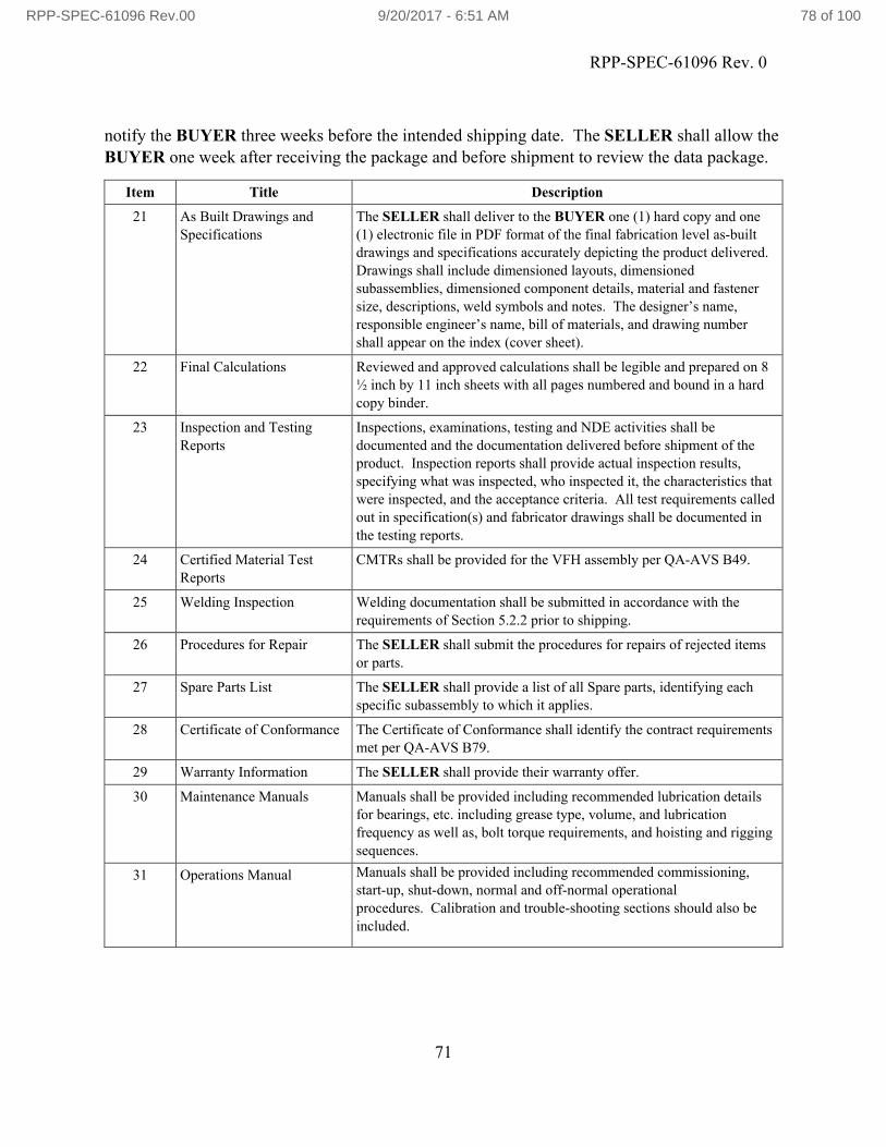
RPP-SPEC-61096 Rev. 0
71
notify the BUYER three weeks before the intended shipping date. The SELLER shall allow the BUYER one week after receiving the package and before shipment to review the data package.
Item Title Description
21 As Built Drawings and Specifications
The SELLER shall deliver to the BUYER one (1) hard copy and one (1) electronic file in PDF format of the final fabrication level as-built drawings and specifications accurately depicting the product delivered. Drawings shall include dimensioned layouts, dimensioned subassemblies, dimensioned component details, material and fastener size, descriptions, weld symbols and notes. The designer’s name, responsible engineer’s name, bill of materials, and drawing number shall appear on the index (cover sheet).
22 Final Calculations Reviewed and approved calculations shall be legible and prepared on 8 ½ inch by 11 inch sheets with all pages numbered and bound in a hard copy binder.
23 Inspection and Testing Reports
Inspections, examinations, testing and NDE activities shall be documented and the documentation delivered before shipment of the product. Inspection reports shall provide actual inspection results, specifying what was inspected, who inspected it, the characteristics that were inspected, and the acceptance criteria. All test requirements called out in specification(s) and fabricator drawings shall be documented in the testing reports.
24 Certified Material Test Reports
CMTRs shall be provided for the VFH assembly per QA-AVS B49.
25 Welding Inspection Welding documentation shall be submitted in accordance with the requirements of Section 5.2.2 prior to shipping.
26 Procedures for Repair The SELLER shall submit the procedures for repairs of rejected items or parts.
27 Spare Parts List The SELLER shall provide a list of all Spare parts, identifying each specific subassembly to which it applies.
28 Certificate of Conformance The Certificate of Conformance shall identify the contract requirements met per QA-AVS B79.
29 Warranty Information The SELLER shall provide their warranty offer.
30 Maintenance Manuals Manuals shall be provided including recommended lubrication details for bearings, etc. including grease type, volume, and lubrication frequency as well as, bolt torque requirements, and hoisting and rigging sequences.
31 Operations Manual Manuals shall be provided including recommended commissioning, start-up, shut-down, normal and off-normal operational procedures. Calibration and trouble-shooting sections should also be included.
RPP-SPEC-61096 Rev.00 9/20/2017 - 6:51 AM 78 of 100

RPP-SPEC-61096 Rev. 0
72
7.2.5 Request For Information
Any changes shall be submitted per the RFI process requirements detailed in TFC-BSM-IRM_DC-C-07, “Vendor Processes.”
7.3 QUALITY ASSURANCE PROGRAM
The SELLER shall conduct work in accordance with a Quality Assurance Program that meets the Quality Assurance (QA) criteria specified by the BUYER using form A-6006-661, “Quality Assurance Requirements.”
The BUYER reserves the right to verify the quality of work at the SELLER’s facilities including any sub-tier facilities. Access to sub-tier facilities shall be requested through the SELLER and verification may be performed jointly with the SELLER.
7.3.1 Non-Conformance Reports
Non-Conformance Reports identified at the SELLER or lower-tier subcontractor’s facility, associated with this Procurement Specification, with a proposed disposition of “Accept as is” or “Repair,” shall be submitted to and approved by Washington River Protection Solutions Engineering and QA before the Subcontractor takes any corrective action on the nonconformance. Submittals must conform to clause QA-AVS B22.
7.3.2 Inspection/Examination
The SELLER shall include the qualifications of the inspectors for all critical items or features identified from the design. Inspections will be performed in accordance with QA Clauses B16 and B19.
The following ASME AG-1 inspections shall be performed and documented by the SELLER
and verified by BUYER:
a) Visual Inspection of all equipment, components, and devices for dimensional tolerances,
fit, and function in accordance with ASME AG-1, Sections AA-5400 & 5500.
b) Fabrication tolerances shall be clearly identified by the SELLER and submitted for
review and approval by the BUYER prior to start of fabrication.
RPP-SPEC-61096 Rev.00 9/20/2017 - 6:51 AM 79 of 100

RPP-SPEC-61096 Rev. 0
73
7.3.3 Suspect/Counterfeit Items
Procurement of genuine, new, and unused parts shall conform to QA-AVS B76, “Procurement of Potentially Suspect or Counterfeit Items.”
7.3.4 Certificate of Conformance
Objective evidence in the form of a written document for all parts procured shall be provided by the SELLER. Documentation shall be in the form of a Certificate of Conformance or CMTR. Certificates of Conformance shall be traceable to the material used in the fabrication as required by ASME AG-1, Article AA-8000, “Quality Assurance,” and shall fulfill the requirements of NQA-1, Requirement 7, paragraph 503, “Certificate of Conformance.” Documentation shall conform to QA-AVS B79, “Certificate of Conformance.”
RPP-SPEC-61096 Rev.00 9/20/2017 - 6:51 AM 80 of 100

RPP-SPEC-61096 Rev. 0
74
8.0 REFERENCES
QA-AVS-APPENDIX, “Procurement Quality Clauses,” Mission Support Alliance, Richland Washington.
TFC-BSM-IRM_DC-C-02, “Records Management”, As Revised, Washington River Protection Solutions, LLC, Richland Washington.
TFC-BSM-IRM_DC-C-07, “Vendor Processes,” As Revised, Washington River Protection Solutions, LLC, Richland Washington.
TFC-ENG-STD-34, “Standard For The Selection of Non-Metallic Materials in Contact With Tank Waste,” As Revised, Washington River Protection Solutions, LLC, Richland Washington.
TFC-ENG-DESIGN-C-57, “Development and Maintenance of Code of Record,” As Revised, Washington River Protection Solutions, LLC, Richland Washington.
TFC-ENG-STD-41, “Electrical Installations,” As Revised, Washington River Protection Solutions, LLC, Richland Washington.
RPP-SPEC-61096 Rev.00 9/20/2017 - 6:51 AM 81 of 100

A - 1
A. EQUIPMENT DATASHEET (SAMPLE)
Field values provided in Datasheets A.1 through A.4 (below) are EXAMPLES ONLY
A.1 FILTER HOUSING ASSEMBLY
Washington River Protection Solutions, LLC.
Mechanical Datasheet Document No. Rev.
PO Box 850, Richland, WA 99352
HEPA Filter Housing Assembly DS-XX-XX-00x Sht. 1 A
Equipment Id. No.:
XX-xxxx Safety Classification/Safety Function: Note 22
Reference Specification:
RPP-SPEC-61096 WAC 246-247-120 Compliance: Yes
P&ID: * AG-1 Service Level: BGeneral Assembly
Drawing:* Performance Category: PC-2
Facility Interface Drawing:
* Seismic Criteria: Note 2
Project Name XX Contract Functional Class
Safety SignificantSystem Ventilation System Acronym * X Radiological Confinement
Project Number xxxxx Function Tank Exhaust General Use
Project Location Hanford Quality Level * Applicable To: ProposalNotes to be completed
by:
Purchaser or Manufacturer
Site 200X Design Life 40 years Quantity Required XApplicable
To: *OPERATING CONDITIONS
1 Location (Indoors/Outdoors) Outdoors
2 Ambient Temp (min/max) (oF) -25/115
3 Ambient Relative Humidity (min/max) (%) 10/100
4 Operating Temp (min/max) (oF) 55/95
5 Operating Relative Humidity (%) 100
6 Elevation (ft) *
7 Lifetime Radiation Dose (Rad) *
8 Gas Molecular Weight (g/mol) *
9 Process Environment (pH) *
10 Process Contents *
11 Radiation Environment? (Yes/No) *
12 Standard Air Temp (AMCA 210) (°F) 68
13 Standard Air Density (AMCA 210) (lbm/ft³) 0.07513 Lifetime Radiation Dose (Rad) *
14 Internal Operating Pressure (min/max) (in w.g.) *
15 Radiation Exposure Rate (Rad/hr) *
16 Application Outdoors
17 Operation (continuous/intermittent) Continuous (24/7/365)
DESIGN/PERFORMANCE REQUIREMENTS18 Housing Type Bag-In/Bag-Out19 Primary Filter Seal Jel Seal
RPP-SPEC-61096 Rev.00 9/20/2017 - 6:51 AM 82 of 100

A - 2
Washington River Protection Solutions, LLC.
Mechanical Datasheet Document No. Rev.
PO Box 850, Richland, WA 99352
HEPA Filter Housing Assembly DS-XX-XX-00x Sht. 1 A
Equipment Id. No.:
XX-xxxx Safety Classification/Safety Function: Note 22
Reference Specification:
RPP-SPEC-61096 WAC 246-247-120 Compliance: Yes
20 Door Access Both Left and Right Hand
21Options
Static Pressure Taps, Mounting Base, Weather Caps, Swivel Door Latches, Intake Fire Screen
22 Space Limitation (If Yes, Explain) 15ft Max Length (Note #)23 Operating Volumetric Flow (cfm) 2400
24 Design Volumetric Flow (cfm) 3000
25 Operating Static Pressure (in w.g.) -45
26 Design Static Pressure (in w.g.) -55
27 Flow Media air
28 Toxic Media None
29 Flammable Media None
30 Gas Tight (Yes/No) *
31 Test Pressure (min/max) (psig) *
32 Corrosion Allowance (in) 0
3 Code Requirements (including tolerances) ASME AG-1, N509, N511, NQA-1
CONFIGURATION REQUIREMENTS
34 SELLER Flanders
35 Model Number *
36 Material of Construction 300 Series Stainless Steel
37 Material Finish 2B Mill Finish, Drilled Flanges, Test Ports
38 Inlet Duct Size (in) 12-inch Sch. 10S Piping
39 Outlet Duct Size (in) 12-inch Sch. 10S Piping
40 Overall Dimensions W x H x D (in) *
41 Weld Inspection Visual and Liquid Penetrant
42 Wall Construction 2 inch (minimum) Double wall with insulation
43 Insulation R Value (hr. oF .ft2 /BTU) 12 (Minimum)
44 Insulation Material Mineral wool
45 Coating None
46 Welding Code ASME AG-1, AWS D1.6, D.1.1
47 Dimensional Tolerances (+/-) *
DESIGN LOADS48 Lifting *49 Shipping *50 Integral Structural Frame (Yes/No) *51 Anchorage *52 Design Load Combinations *53 Seismic *54 Thermal Forces *55 Wind *56 Snow *57 Ashfall *58 Integral Structural Frame Material *59 MOP (enveloping SOPD and NOPD) *60 Additional Dynamic Load *61 Live *62 Dead *63 Deflection Limits 0.0042 inches per inch of panel span (max)
FILTER DATA64 Prefilter (quantity, size, type): *
65 Filter Efficiency See Data Sheet DS-XX-XX
RPP-SPEC-61096 Rev.00 9/20/2017 - 6:51 AM 83 of 100

A - 3
Washington River Protection Solutions, LLC.
Mechanical Datasheet Document No. Rev.
PO Box 850, Richland, WA 99352
HEPA Filter Housing Assembly DS-XX-XX-00x Sht. 1 A
Equipment Id. No.:
XX-xxxx Safety Classification/Safety Function: Note 22
Reference Specification:
RPP-SPEC-61096 WAC 246-247-120 Compliance: Yes
66 Filter Media *
67 Filter Face Velocity *
68 Filter Rated Airflow *
69 Initial Internal Resistance *
70 Sealant Material Blue-Jel Seal
71 Certification Per AG-1
72 HEPA(quantity, size, type): *
73 Filter Ratings See Data Sheet DS-XX-XX
74 Filter Media *
75 Filter Face Velocity *
76 Filter Rated Airflow *
77 Initial Internal Resistance *
78 Sealant Material Blue-Jel Seal
79 Certification Per AG-1 See Note 3
DAMPERS80 Inlet (specify) Yes
81 Outlet (specify) Yes
82 Design Seismic SDC 2 - Limit State C
83 Design Wind 115 mph, Performance Criteria PC-2
84 Design Temperature -25 to 115 oF
85 Load Combinations ASME AG-1, Section HA, Service Level B
86 MOP (enveloping SOPD and NOPD) *
87 Design Load Combinations Note *
88 Additional Dynamic Load none
89 Snow Loads *
90 Outlet (specify) Yes
91 Leakage rate ASHRAE 90.1
92 Shape (circle, square, size) *
93 Manual Operator (F/CSC Standard) Yes
94 Electric Operator (explain voltage, options, etc.) N/A
95 Pneumatic Operator (explain pressure, options, etc.) N/A
INSTRUMENTS AND CONTROLS OPTIONS96 Installed Magnetic Gage No
97 Gage Piped w/ SST Tubing Yes
98Installed Differential Pressure Gages w/ Adjustable high and low pressure switches
No
99 Terminal Boxes - For Power and Control / Size *
100 Gage Piped w/ Copper Tubing No
101 Hz 60
102 Temperature Switch High (at inlet of outlet) none
ACCESSORIES103 Inlet and Outlet Duct Flanges with Transitions 12-inch, RF, 150 Lb
104 Test Sections HEPA Inlet, Combination and HEPA Outlet
105 Heater Section See Data Sheet DS-XX-XX
106 Structural Base per SELLER Std design
107 Gasket *
108 Flanges *
109 Filter Bag in Bag Out Flange per SELLER Std design
110 Differential Pressure Gauge Interface at Prefilter, 1'st stage and 2'nd stage
111 Humidity Sensor Interface *
RPP-SPEC-61096 Rev.00 9/20/2017 - 6:51 AM 84 of 100

A - 4
Washington River Protection Solutions, LLC.
Mechanical Datasheet Document No. Rev.
PO Box 850, Richland, WA 99352
HEPA Filter Housing Assembly DS-XX-XX-00x Sht. 1 A
Equipment Id. No.:
XX-xxxx Safety Classification/Safety Function: Note 22
Reference Specification:
RPP-SPEC-61096 WAC 246-247-120 Compliance: Yes
112 Filter Removal Tray and Tools *
113 Drain Connections *
114 Swivel Door Latches *
115 Lighting *
116 Clamping Mechanism *
117 Lifting Lugs per SELLER Std design
FABRICATION118 Material ID *119 Welding *
120 Flatness *
121 Metal Coating *122 Inside Bend Radii *123 Joining Parts *124 Nuts *125 Surface Finish *126 High Strength Bolts *
127 Pins *
REQUIRED SPARE PARTS SUBSYSTEM CONSTRUCTION
128 * * *
129 * * *
130 * * *
INSPECTION 131 Joints and Seams *
132 Stiffeners *
133 Housing Supports *
134 Mounting Frame To Housing Leakage Test *
135 Filter Mounting Frame To Housing Weld Inspection *
TESTING136 Housing Pressure Test *
137 Housing Leakage Rates by Section *
138 Pressure Boundary Leakage Tests *
139 Quantitative/Non-quantitative Leakage Tests *
140 Airflow Distribution Tests *
141 Air Conditioning and Air Handling Unit Testing *
142 Sampling Manifold Tests *
143 Air-Aerosol Mixing Uniformity Tests *
QUALIFICATION TESTING144 Seismic Testing *145 Leakage Test *146 Mechanical Running Test *147 Vibration Test *148 Performance Test *149 Air Flow Resistance Test *
150 Minimum burst pressure differential *
SELLER DATA151 SELLER Flanders or Equal
152 Model *
153 Model Number *
RPP-SPEC-61096 Rev.00 9/20/2017 - 6:51 AM 85 of 100

A - 5
Washington River Protection Solutions, LLC.
Mechanical Datasheet Document No. Rev.
PO Box 850, Richland, WA 99352
HEPA Filter Housing Assembly DS-XX-XX-00x Sht. 1 A
Equipment Id. No.:
XX-xxxx Safety Classification/Safety Function: Note 22
Reference Specification:
RPP-SPEC-61096 WAC 246-247-120 Compliance: Yes
154 Rigging Weight (lb) *
155 Installed Weight (lb) *
CONTROL DATA156 Unit Controller PLC controller is not part of housing SELLER scope.
157 Volume Control VFD equipped fan with direct drive. VFD/fan is not part of housing SELLER scope.
158 Flow MonitoringDischarge flow transmitter/element installed in supply ductwork. Flow transmitter is not part of housing SELLER scope.
159 Remarks: Filter housing to be assembled on a base frame with Process Heater and Exhaust fans.
160 Receipt Verifications: Verify Model Number
161 Required Documentation YesCertified Material Test Report
Yes Calibration Certificate
162(verify at Receipt Inspection)
YesPositive Material Identification
YesCalibration Traceable to NIST
163 YesCertificate of Conformance
Yes O&M Manual
164 Yes SELLER's Data YesNRTL Certification or Label
165 Notes:
166 Note 1 Asterisk (*) data to be supplied by SELLER.
167 Note 2Seismic loads in accordance with IBC 2012 and AG-1 AA-4321For Occupancy Category IV, Seismic Design Category D, Site Class C and an Importance Factor of 1.5. Use site specific
accelerations of 1) horizontal SD1 = 0.192 and SDS = 0.588, 2) vertical SD1 = 0.098 and SDS = 0.346.
168 Note 3SELLER to supply HEPA filters that have been tested at the Filter Test Facility (FTF) - a facility accepted by the USDOE as identified in DOE-STD-3025-99, upon successful inspections per section 6 and testing per section 7.
169 Note 4Maximum Operating Pressure, envelopes normal operating pressure difference (NOPD) and system operating pressure
transient (SOPT). Deadhead Pressure of system is 20" wc.
170 Note 5 See Specification _______ - Safety Systems and Components Natural Phenomena Hazard Performance Requirements.
171 Note 6 A stamped structural analysis calculation required per specification ______ - Filter Housings paragraph 1.5.
172 Note 7 Label per ________. Label to include: EXHAUST FILTER HOUSING SKID BAR CODE (TBD)
173 Note 8 This Data Sheet covers tag numbers all preceded by ______
174 Note 9 Safety Significant Function is maintaining the pressure boundary leakage requirements.
175 Note 10 Refer to Filter Housing specification ________ Paragraph 1.8.3 for ambient (surface) environments.
176 Note 11 Provide instrumentation as noted in Filter Housing specification
177 Note 13Average atmospheric dust spot efficiency shall be as measured by ASHRAE 52.1, “Method of Testing General Ventilation Air-Cleaning Devices for Removal Efficiency by Particle Size”. MERV rating shall be as measured by ASHRAE 52.2.
178 Note 14Electrical equipment must be listed or labeled by UL or another OSHA approved Nationally Recognized Testing Laboratory (NRTL) standards
179 Note 15 Maximum Total Leakage rate is ______
180 Note 16 SELLER listed or approved equal.
181 Note 17 Safety Function: Contamination Confinement
182 Note 18 VFH Performance Testing shall be done per AG-1 Sections ______
183 Note 19 Structural member selection and/or testing requirements per ______
184 Note 20 Components requiring Positive Material Identification spectrographic analysis include: ______
185 Note 21 (Any Electrical interface requirements)
186Note 22
Safety Function Radiological Confinement
187 Critical Characteristics N/A
RPP-SPEC-61096 Rev.00 9/20/2017 - 6:51 AM 86 of 100

A - 6
Washington River Protection Solutions, LLC.
Mechanical Datasheet Document No. Rev.
PO Box 850, Richland, WA 99352
HEPA Filter Housing Assembly DS-XX-XX-00x Sht. 1 A
Equipment Id. No.:
XX-xxxx Safety Classification/Safety Function: Note 22
Reference Specification:
RPP-SPEC-61096 WAC 246-247-120 Compliance: Yes
188 Hold Points See Specification RPP-SPEC-______
189 Note 23 Refer to the Master Submittal Registry in the Statement of Work for complete list of required submittals
190 Note 24 UNITS191 °F Degrees Fahrenheit
192 BTU British Thermal Units
193 cfm cubic feet per minute
194 ft feet
195 ft2 feet squared
196 g/mol grams per mole
197 hr hour
198 Hz Hertz
199 in inch
200 in w.g. inches of water (inch water gauge)
201 lb pound
202 mph miles per hour
203 psig pound(s) per square inch gauge
204 Rad /Rad/hr unit of radiation dose (per hour)
Rev Date Revision Status Originator Checker ApproverA Preliminary - Issued for Design Review
RPP-SPEC-61096 Rev.00 9/20/2017 - 6:51 AM 87 of 100

A - 7
A.2 HEATER
Washington River Protection Solutions, LLC.
Mechanical Datasheet Document No. Rev. Tag No.
PO Box 850, Richland, WA 99352 Heater DS-XX-XX-00x Sht. 1 A XX
Equipment Id. No.: XX-xxxx Safety Classification/Safety Function: Note 11
Reference Specification: RPP-SPEC-61096 WAC 246-247-120 Compliance: Yes
P&ID: * AG-1 Service Level: BGeneral Assembly
Drawing:* Performance Category: PC-2
Facility Interface Drawing:
* Seismic Criteria: Note 2
Project Name XX Contract Functional Class
Safety Significant
System VentilationSystem
Acronym* X Radiological Confinement
Project Number xxxxx Function Tank Exhaust General Use
Project Location HanfordQuality
Level*
Applicable To:
ProposalNotes to be completed
by:
Purchaser or Manufacturer
Site 200X Design Life 40 yearsQuantity Required
XApplicable
To:*
OPERATING CONDITIONS
1 Location (Indoors/Outdoors) Outdoors
2 Ambient Temp (min/max) (oF) -25/115
3 Ambient Relative Humidity (min/max) (%) 10/100
4 Operating Temp (min/max) (oF) 55/95
5 Temp (in/out) (oF) *
6 Operating Relative Humidity (%) 100
7 Elevation (ft) *
8 Lifetime Radiation Dose (Rad) *
9 Gas Molecular Weight (g/mol) *
10 Process Environment (pH) *
11 Process Contents *
12 Standard Air Temp (AMCA 210) (°F) 68
13 Standard Air Density (AMCA 210) (lbm/ft³) 0.07514 Radiation Environment? (Yes/No) *
15 Lifetime Radiation Dose (Rad) *
16 Internal Operating Pressure (min/max) (in w.g.) *
17 Radiation Exposure Rate (Rad/hr) *
18 Operation (continuous/intermittent) Continuous (24/7/365)
DESIGN/PERFORMANCE REQUIREMENTS
19 Operating Volumetric Flow (cfm) 2400
20 Design Volumetric Flow (cfm) 3000
21 Operating Static Pressure (in w.g.) -45
22 Design Static Pressure (in w.g.) -55
23 Flow Media air
24 Toxic Media None
25 Flammable Media None
26 Gas Tight (Yes/No) *
27 Test Pressure (min/max) (psig) *
28 Corrosion Allowance (in) *
29 Code Requirements (including tolerances) ASME AG-1, N509, N511, NQA-1
RPP-SPEC-61096 Rev.00 9/20/2017 - 6:51 AM 88 of 100

A - 8
Washington River Protection Solutions, LLC.
Mechanical Datasheet Document No. Rev. Tag No.
PO Box 850, Richland, WA 99352 Heater DS-XX-XX-00x Sht. 1 A XX
Equipment Id. No.: XX-xxxx Safety Classification/Safety Function: Note 11
Reference Specification: RPP-SPEC-61096 WAC 246-247-120 Compliance: Yes
CONFIGURATION REQUIREMENTS
30 SELLER Flanders
31 Model Number *
32 Material of Construction 300 Series Stainless Steel
33 Inlet Duct Size (in) 12-inch Sch. 10S Piping
34 Outlet Duct Size (in) 12-inch Sch. 10S Piping
31 Overall Dimensions W x H x D (in) *
32 Weld Inspection Piping Visual and Liquid Penetrant
33 Weld Inspection Structural Visual
34 Welding Code Structure AWS D1.1, D.1.6
35 Welding Code Piping ASME AG-1
36 Piping Code ASME AG-1
37 Pressure Vessel Code ASME Section VIII, Div. 138 Dimensional Tolerances (+/-) *
COIL DATA
39 General Description Heating Coil
40 Number of Steps 1
41 Step Control none
42 Coil Capacity (kW) 2
43 Heating Load (MBh) *
44 Entering Air Temp (°F) *
45 Air Temp Differential (°F) 15 (Minimum)
46 Coil Type *
47 Corrosion Allowance (in) *
48 Certification Per AG-1
49 Heating Medium 40-60 Propylene Glycol-Water
50 Operating Pressure (psig) *
51 Pressure Drop Across Coils *
52 Design Pressure (psig) 150
53 Operating Temperature (°F) *
54 Design Temperature (°F) *55 Hydrostatic Pressure (psig) *
PUMP DATA
56 Pump Type Centrifugal
57 Material of Constr. (Casing/Impel/seals) Stainless Steel/Stainless Steel/EPDM
58 Volumetric flow (gpm) *
59 Solids (Weight %) *
60 Total Discharge Head (ft) *
61 NPSH Required (ft) *
62 NPSH Available (ft) *
63 Electric Supply 480/60/3
64 Suction/Discharge Nozzle Size & Rating *
65 Pump Certifications *
66 Motor Power (hp) *
67 Motor Speed (rpm) *
68 Motor Type TEFC
69 Motor Frame Size *
70 Electrical Certifications NEMA MG-1 and Note 5
HEATER DATA
71 Heater Type Immersion/flow thru
RPP-SPEC-61096 Rev.00 9/20/2017 - 6:51 AM 89 of 100

A - 9
Washington River Protection Solutions, LLC.
Mechanical Datasheet Document No. Rev. Tag No.
PO Box 850, Richland, WA 99352 Heater DS-XX-XX-00x Sht. 1 A XX
Equipment Id. No.: XX-xxxx Safety Classification/Safety Function: Note 11
Reference Specification: RPP-SPEC-61096 WAC 246-247-120 Compliance: Yes
72 Material of Construction Stainless Steel
73 Sheath Material Stainless Steel
74 Fin Material Stainless Steel
75 Mounting Integral
76 Volumetric flow (gpm) *
77 Supply/Discharge Nozzle Size & Rating *
78 Housing Design Pressure (psig) *
79 Housing Design Temperature (°F) *
80 Housing Hydrostatic Test Pressure (psig) *
81 Electrical Certification Note 5
82 Corrosion Allowance (in) *
83 Housing Code Report *
84 Electrical Supply (V/hz/Phase) 480/60/3
85 Heater Power (kw) *
86 Heater Element Construction *
87 Materials - Sheath/Insul./Element Stainless steel/MgO/NiChrome
88 Heater Max Watt Density (watts/sq. in.) *
89 Element Size Blue-Jel Seal
90 Number of Elements Per AG-1 See Note 3
ACCESSORIES
91 Panel *
92 High High Temp Cut-Out Switch *
93 Manual Cut-Out Switch *
94 Gasket *
95 Mounting Flange *
96 Temperature Port(s) (Quantity, Fitting) *
97 Drains *
98 Pressure Port(s) (Quantity, Fitting) *
99 Auto and Manual High Limit *
100 Status Indication *
101 Panel w/Locking Disconnect *
102 Air Pressure Switch *
103 Explosion proof controls and cabinet *
104 Clamping Mechanism *
FABRICATION
104 Material ID *
105 Welding *
105 Flatness *
106 Metal Coating *
106 Inside Bend Radii *
107 Joining Parts *
107 Nuts *
108 Surface Finish *
109 High Strength Bolts *
110 Pins *
REQUIRED SPARE PARTS SUBSYSTEM CONSTRUCTION
111 * * *
112 * * *
113 * * *
INSPECTION
RPP-SPEC-61096 Rev.00 9/20/2017 - 6:51 AM 90 of 100

A - 10
Washington River Protection Solutions, LLC.
Mechanical Datasheet Document No. Rev. Tag No.
PO Box 850, Richland, WA 99352 Heater DS-XX-XX-00x Sht. 1 A XX
Equipment Id. No.: XX-xxxx Safety Classification/Safety Function: Note 11
Reference Specification: RPP-SPEC-61096 WAC 246-247-120 Compliance: Yes
114 Heater InspectionN/A (Subject to BUYER field inspection per AG-1 Section TA
TESTING
115 Heater Testing N/A (Subject to BUYER field Testing per AG-1 Section TA
QUALIFICATION TESTING
116 Seismic Testing *
117 Leakage Test *
118 Mechanical Running Test *
119 Vibration Test *
120 Performance Test *
121 Air Flow Resistance Test *
SELLER DATA
122 SELLER Flanders or Equal
123 Model *
124 Model Number *
125 Lifting Lug Number *
126 Rigging Weight (lb) *
127 Installed Weight (lb) *
CONTROL DATA
128 Unit Controller PLC controller is not part of housing SELLER scope.
128 Volume Control VFD equipped fan with direct drive. VFD/fan is not part of housing SELLER scope.
129 Flow MonitoringDischarge flow transmitter/element installed in supply piping. Flow transmitter is not part of pump assembly SELLER scope.
130 Remarks: Pump/heater and accessories to be assembled on a base frame.
131 Receipt Verifications: Verify Model Number
132Required Documentation: See Procurement Specification
Yes Certified Material Test Report Yes Calibration Certificate
133 (verify at Receipt Inspection) Yes Positive Material Identification Yes Calibration Traceable to NIST
134 Yes Certificate of Conformance Yes O&M Manual
135 Yes SELLER's Data Yes NRTL Certification or Label
136 Notes:
137 Note 1 Asterisk (*) data to be supplied by SELLER.
138 Note 2Seismic loads in accordance with IBC 2012 and AG-1 AA-4321 for Occupancy Category IV, Seismic Design Category D, Site Class C and an Importance Factor of 1.5. Use site specific accelerations of 1) horizontal SD1 = 0.192 and SDS = 0.588, 2) vertical SD1 = 0.098 and SDS = 0.346.
139 Note 3SELLER to supply HEPA filters that have been tested at the Filter Test Facility (FTF) - a facility accepted by the USDOE as identified in DOE-STD-3025-99, upon successful inspections per section 6 and testing per section 7.
140 Note 4Average atmospheric dust spot efficiency shall be as measured by ASHRAE 52.1. MERV rating shall be as measured by ASHRAE 52.2.
141 Note 5Electrical equipment must be listed or labeled by UL or another OSHA approved Nationally Recognized Testing Laboratory (NRTL) standards
142 Note 6 Maximum Total Leakage rate is ______
143 Note 7 SELLER listed or approved equal.
144 Note 8 Safety Function: Contamination Confinement
145 Note 9 Structural member selection and/or testing requirements per ______
146 Note 10 Components requiring Positive Material Identification spectrographic analysis include: ______
147
Note 11
Safety Function Radiological Confinement
148 Critical Characteristics N/A
149 Hold Points See Specification RPP-SPEC-______
150 Note 12 Refer to the Master Submittal Registry in the Statement of Work for complete list of required submittals
151 Note 13 UNITS
152 °F Degrees Fahrenheit
RPP-SPEC-61096 Rev.00 9/20/2017 - 6:51 AM 91 of 100

A - 11
Washington River Protection Solutions, LLC.
Mechanical Datasheet Document No. Rev. Tag No.
PO Box 850, Richland, WA 99352 Heater DS-XX-XX-00x Sht. 1 A XX
Equipment Id. No.: XX-xxxx Safety Classification/Safety Function: Note 11
Reference Specification: RPP-SPEC-61096 WAC 246-247-120 Compliance: Yes
153 cfm cubic feet per minute
154 ft feet
155 g/mol grams per mole
156 gpm gallons per minute
157 hp horsepower
158 in inch
159 in w.g. inches of water (inch water gauge)
160 kw Kilo-watt
161 lb pound
162 MBh 1000 British Thermal Units (BTU) per hour
163 psig pound(s) per square inch gauge
164 Rad /Rad/hr unit of radiation dose (per hour)
165 rpm revolutions per minute
166 V/hz/Phase Volts per hertz phase
167 watts/ sq in watts per square inch
Rev Date Revision Status Originator Checker
A Preliminary - Issued for Design Review
RPP-SPEC-61096 Rev.00 9/20/2017 - 6:51 AM 92 of 100

A - 12
A.3 PRE-FILTER
Washington River Protection Solutions, LLC. Mechanical Datasheet Document No. Rev. Tag No.
PO Box 850, Richland, WA 99352 Pre-Filter DS-XX-XX-00x Sht. 1 A XX
Equipment Id. No.: XX-xxxxSafety Classification/Safety
Function:Note 13
Reference Specification: RPP-SPEC-61096 WAC 246-247-120 Compliance: YesP&ID: * AG-1 Service Level: B
General Assembly Drawing: * Performance Category: PC-2
Facility Interface Drawing: * Seismic Criteria: Note 2
Project Name XX Contract Functional
Class
Safety Significant
System VentilationSystem
Acronym* X Radiological Confinement
Project Number xxxxx Function Tank Exhaust General Use
Project Location HanfordQuality
Level*
Applicable To:
ProposalNotes to be completed
by:
Purchaser or Manufacturer
Site 200XDesign
Life40 years
Quantity Required
XApplicable
To: *
OPERATING CONDITIONS1 Location (Indoors/Outdoors) Outdoors2 Ambient Temp (min/max) (oF) -25/1153 Ambient Relative Humidity (min/max) (%) 10/1004 Operating Temp (min/max) (oF) 55/955 Operating Relative Humidity (%) 1006 Elevation (ft) *7 Lifetime Radiation Dose (Rad) *8 Gas Molecular Weight (g/mol) *9 Process Environment (pH) *
10 Process Contents *11 Radiation Environment? (Yes/No) *12 Standard Air Temp (AMCA 210) (°F) 6813 Standard Air Density (AMCA 210) (lbm/ft³) 0.07514 Lifetime Radiation Dose (Rad) *15 Internal Operating Pressure (min/max) (in w.g.) *16 Radiation Exposure Rate (Rad/hr) *17 Operation (continuous/intermittent) Continuous (24/7/365)
DESIGN/PERFORMANCE REQUIREMENTS18 Operating Volumetric Flow (cfm) 240019 Design Volumetric Flow (cfm) 300020 Operating Static Pressure (in w.g.) -4521 Design Static Pressure (in w.g.) -5522 Flow Media air23 Toxic Media None24 Flammable Media None25 Gas Tight (Yes/No) *26 Test Pressure (min/max) (psig) *27 Corrosion Allowance (in) 028 Code Requirements (including tolerances) ASME AG-1, N509, N511, NQA-1
CONFIGURATION REQUIREMENTS29 SELLER Flanders30 Model Number *31 Material of Construction 300 Series Stainless Steel
RPP-SPEC-61096 Rev.00 9/20/2017 - 6:51 AM 93 of 100

A - 13
Washington River Protection Solutions, LLC. Mechanical Datasheet Document No. Rev. Tag No.
PO Box 850, Richland, WA 99352 Pre-Filter DS-XX-XX-00x Sht. 1 A XX
Equipment Id. No.: XX-xxxxSafety Classification/Safety
Function:Note 13
Reference Specification: RPP-SPEC-61096 WAC 246-247-120 Compliance: Yes32 Inlet Duct Size (in) 12-inch Sch. 10S Piping33 Outlet Duct Size (in) 12-inch Sch. 10S Piping31 Overall Dimensions W x H x D (in) *32 Weld Inspection Visual and Liquid Penetrant33 Wall Construction 2 inch (minimum) Double wall with insulation34 Insulation R Value N/A35 Insulation Material N/A36 Coating None37 Welding Code ASME AG-1, AWS D1.6, D.1.138 Dimensional Tolerances (+/-) *
FILTER DATA39 SELLER Flanders or Equal40 Model Number *41 Material of Construction *42 Frame Material Galvaneal43 Overall Dimensions W x H x D (in) *44 Filter Ratings 80% Min. and Note 445 MERV Rating (Efficiency) 13 46 Filter Media *47 Filter Face Velocity (fpm) 50048 Filter Rated Airflow (acfm) *49 Initial Internal Resistance (in w.g.) *50 Final Internal Resistance (in w.g.) *51 Sealant Material Blue-Jel Seal52 Casing Material *53 Facing Material *54 Actual Size (per Filter Element) *55 Height x Width (in) *56 Thickness (in) *57 Filter Area (per filter element) (ft2) *58 Certification UL 900, Class 2, ISO-9001
ACCESSORIES59 Filter Removal Rod *60 Drain *61 Change Out Bag *62 Gasket *63 Pressure Port(s) (Quantity, Fitting) *64 Housing Access Door for Filter Change Out *65 Housing Access Door Drain Port *66 Housing Access Door Seal Lip *67 Flange *68 Tie-Down Latch *
FABRICATION69 Material ID *70 Welding *71 Flatness *72 Metal Coating *73 Inside Bend Radii *74 Joining Parts *75 Nuts *76 Surface Finish *77 High Strength Bolts *78 Pins *
REQUIRED SPARE PARTS SUBSYSTEM CONSTRUCTION
RPP-SPEC-61096 Rev.00 9/20/2017 - 6:51 AM 94 of 100

A - 14
Washington River Protection Solutions, LLC. Mechanical Datasheet Document No. Rev. Tag No.
PO Box 850, Richland, WA 99352 Pre-Filter DS-XX-XX-00x Sht. 1 A XX
Equipment Id. No.: XX-xxxxSafety Classification/Safety
Function:Note 13
Reference Specification: RPP-SPEC-61096 WAC 246-247-120 Compliance: Yes79 * * *80 * * *81 * * *
INSPECTION
84 Prefilter ElementN/A (Subject to BUYER field inspection per AG-1 Section TA
TESTING
85 Prefilter ElementN/A (Subject to BUYER field Testing per AG-1 Section TA
QUALIFICATION TESTING86 Seismic Testing *87 Leakage Test *88 Performance Test *89 Air Flow Resistance Test *90 Mechanical Running Test *91 Vibration Test *
SELLER DATA92 SELLER Flanders or Equal93 Model *94 Model Number *95 Rigging Weight (lb) *96 Installed Weight (lb) *
97 Remarks:
98 Receipt Verifications: Verify Model Number
99Required Documentation: See Procurement Specification
Yes Certified Material Test Report Yes Calibration Certificate
100 (verify at Receipt Inspection) Yes Positive Material Identification Yes Calibration Traceable to NIST
101 Yes Certificate of Conformance Yes O&M Manual
102 Yes SELLER's Data Yes NRTL Certification or Label
103 Notes:104 Note 1 Asterisk (*) data to be supplied by SELLER.
105 Note 2Seismic loads in accordance with IBC 2012 and AG-1 AA-4321 for Occupancy Category IV, Seismic Design Category D, Site Class C and an Importance Factor of 1.5. Use site specific accelerations of 1) horizontal SD1 = 0.192 and SDS = 0.588, 2) vertical SD1 = 0.098 and SDS = 0.346.
106 Note 3SELLER to supply HEPA filters that have been tested at the Filter Test Facility (FTF) - a facility accepted by the USDOE as identified in DOE-STD-3025-99, upon successful inspections per section 6 and testing per section 7.
107 Note 4Average atmospheric dust spot efficiency shall be as measured by ASHRAE 52.1. MERV rating shall be as measured by ASHRAE 52.2.
108 Note 5Electrical equipment must be listed or labeled by UL or another OSHA approved Nationally Recognized Testing Laboratory (NRTL) standards
109 Note 6 Provide initial set of high efficiency pre-filters plus 10% spares shipped with Housing.110 Note 7 Upstream of the Prefilters provide a Bag-in/Bag-out Fire Screen.111 Note 8 Maximum Total Leakage rate is ______ 112 Note 9 SELLER listed or approved equal.113 Note 10 Safety Function: Contamination Confinement114 Note 11 Structural member selection and/or testing requirements per ______115 Note 12 Components requiring Positive Material Identification spectrographic analysis include: ______116
Note 13Safety Function Radiological Confinement
117 Critical Characteristics N/A
RPP-SPEC-61096 Rev.00 9/20/2017 - 6:51 AM 95 of 100

A - 15
Washington River Protection Solutions, LLC. Mechanical Datasheet Document No. Rev. Tag No.
PO Box 850, Richland, WA 99352 Pre-Filter DS-XX-XX-00x Sht. 1 A XX
Equipment Id. No.: XX-xxxxSafety Classification/Safety
Function:Note 13
Reference Specification: RPP-SPEC-61096 WAC 246-247-120 Compliance: Yes118 Hold Points See Specification RPP-SPEC-______119 Note 14 Refer to the Master Submittal Registry in the Statement of Work for complete list of required submittals120 Note 15 UNITS121 °F Degrees Fahrenheit122 acfm actual cubic feet per minute123 cfm cubic feet per minute124 fpm feet per minute125 ft feet126 ft2 feet squared
127 g/mol grams per mole
128 in inch129 in w.g. inches of water (inch water gauge)130 lb pound131 psig pound(s) per square inch gauge132 Rad /Rad/hr unit of radiation dose (per hour)Rev Date Revision Status Originator Checker Approver
APreliminary - Issued for
Design Review
RPP-SPEC-61096 Rev.00 9/20/2017 - 6:51 AM 96 of 100

A - 16
A.4 HEPA FILTER
Washington River Protection Solutions, LLC.
Mechanical Datasheet Document No. Rev. Tag No.
PO Box 850, Richland, WA 99352 HEPA Filter DS-XX-XX-00x Sht. 1 A XX
Equipment Id. No.: XX-xxxxSafety Classification/Safety
Function:Note 12
Reference Specification: RPP-SPEC-61096 WAC 246-247-120 Compliance: YesP&ID: * AG-1 Service Level: B
General Assembly Drawing:
* Performance Category: PC-2
Facility Interface Drawing:
* Seismic Criteria: Note 2
Project Name XX Contract Functional Class Safety Significant
System VentilationSystem
Acronym* X Radiological Confinement
Project Number xxxxx FunctionTank
ExhaustGeneral Use
Project Location Hanford Quality Level * Applicable To: ProposalNotes to be completed
by:
Purchaser or Manufacturer
Site 200X Design Life 40 yearsQuantity Required
(stages)X
Applicable To:
OPERATING CONDITIONS1 Location (Indoors/Outdoors) Outdoors2 Ambient Temp (min/max) (oF) -25/1153 Ambient Relative Humidity (min/max) (%) 10/1004 Operating Temp (min/max) (oF) 55/955 Operating Relative Humidity (%) 1006 Elevation (ft) *7 Lifetime Radiation Dose (Rad) *8 Gas Molecular Weight (g/mol) *9 Process Environment (pH) *10 Process Contents *11 Radiation Environment? (Yes/No) *12 Standard Air Temp (AMCA 210) (°F) 6813 Standard Air Density (AMCA 210) (lbm/ft³) 0.07514 Lifetime Radiation Dose (Rad) *15 Internal Operating Pressure (min/max) (in w.g.) *16 Radiation Exposure Rate (Rad/hr) *17 Operation (continuous/intermittent) Continuous (24/7/365)
DESIGN/PERFORMANCE REQUIREMENTS18 Operating Volumetric Flow (cfm) 240019 Design Volumetric Flow (cfm) 300020 Operating Static Pressure (in w.g.) -4521 Design Static Pressure (in w.g.) -5522 Flow Media air23 Toxic Media None24 Flammable Media None25 Gas Tight (Yes/No) *26 Test Pressure (min/max) (psig) *27 Corrosion Allowance (in) 028 Code Requirements (including tolerances) ASME AG-1, N509, N511, NQA-1
FILTER DATA29 SELLER Flanders or Equal
RPP-SPEC-61096 Rev.00 9/20/2017 - 6:51 AM 97 of 100

A - 17
Washington River Protection Solutions, LLC.
Mechanical Datasheet Document No. Rev. Tag No.
PO Box 850, Richland, WA 99352 HEPA Filter DS-XX-XX-00x Sht. 1 A XX
Equipment Id. No.: XX-xxxxSafety Classification/Safety
Function:Note 12
Reference Specification: RPP-SPEC-61096 WAC 246-247-120 Compliance: Yes30 Model Number *31 Material of Construction *32 Frame Material *33 Overall Dimensions W x H x D (in) *34 Filter Ratings 99.99% Min. and Note 435 MERV Rating *36 Filter Media *37 Filter Face Velocity (fpm) 50038 Filter Rated Airflow (acfm) *39 Initial Internal Resistance (in w.g.) *40 Final Internal Resistance (in w.g.) *41 Sealant Material Blue-Jel Seal42 Casing Material *43 Facing Material *44 Actual Size (per Filter Element) *45 - Height x Width (in) *46 - Thickness (in) *47 - Filter Area (per filter element) (ft2) *48 Dimensional Tolerances (+/-) *49 Certification UL 900, Class 2, ISO-9001
Test Sections
50TS Series for In-Place Upstream of HEPA for Testing (TYP of two places)
Yes
52TS Series for In-Place Downstream of HEPA for Testing (TYP of two places)
Yes
53TS Series for In-Place Downstream of HEPA Scan Testing (Primary Filter Must be Scan Type)
No
ACCESSORIES54 Filter Removal Rod *55 Drain *56 Change Out Bag *57 Gasket *58 Pressure Port(s) (Quantity, Fitting, Grade) *59 Temperature Port(s) (Quantity, Fitting) *60 Housing Access Door for Filter Change Out *61 Housing Access Door Drain Port *62 Housing Access Door Seal Lip *63 Flange *64 Tie-Down Latch *
FABRICATION65 Material ID *66 Welding *67 Flatness *68 Metal Coating *69 Inside Bend Radii *70 Joining Parts *71 Nuts *72 Surface Finish *73 High Strength Bolts *74 Pins *
REQUIRED SPARE PARTS SUBSYSTEM CONSTRUCTION75 * * *
RPP-SPEC-61096 Rev.00 9/20/2017 - 6:51 AM 98 of 100

A - 18
Washington River Protection Solutions, LLC.
Mechanical Datasheet Document No. Rev. Tag No.
PO Box 850, Richland, WA 99352 HEPA Filter DS-XX-XX-00x Sht. 1 A XX
Equipment Id. No.: XX-xxxxSafety Classification/Safety
Function:Note 12
Reference Specification: RPP-SPEC-61096 WAC 246-247-120 Compliance: Yes76 * * *77 * * *
INSPECTION 78 Filter Element Assembly N/A (Subject to BUYER field inspection per AG-1 Section TA
TESTING79 Filter Element Assembly N/A (Subject to BUYER field Testing per AG-1 Section TA
QUALIFICATION TESTING80 Seismic Testing *81 Leakage Test *82 Performance Test *83 Air Flow Resistance Test *84 Mechanical Running Test *85 Vibration Test *
SELLER DATA86 SELLER Flanders or Equal87 Model *88 Model Number *89 Rigging Weight (lb) *90 Installed Weight (lb) *
91 Remarks:
92Receipt Verifications:
Verify Model Number
93
Required Documentation: See Procurement Specification
Yes Certified Material Test Report
Yes
Calibration Certificate
94(verify at Receipt Inspection)
YesPositive Material Identification
Yes Calibration Traceable to NIST
95 Yes Certificate of Conformance Yes O&M Manual
96 Yes SELLER's Data Yes NRTL Certification or Label
97 Notes:98 Note 1 Asterisk (*) data to be supplied by SELLER.
99 Note 2Seismic loads in accordance with IBC 2012 and AG-1 AA-4321 for Occupancy Category IV, Seismic Design Category D, Site Class C and an Importance Factor of 1.5. Use site specific accelerations of 1) horizontal SD1 = 0.192 and SDS = 0.588, 2) vertical SD1 = 0.098 and SDS = 0.346.
100 Note 3SELLER to supply HEPA filters that have been tested at the Filter Test Facility (FTF) - a facility accepted by the USDOE as identified in DOE-STD-3025-99, upon successful inspections per section 6 and testing per section 7.
101 Note 4Average atmospheric dust spot efficiency shall be as measured by ASHRAE 52.1. MERV rating shall be as measured by ASHRAE 52.2.
102 Note 5 Provide initial set of HEPA filters plus 20% spare HEPA filters shipped to DOE Filter Test Facility.
103 Note 5Electrical equipment must be listed or labeled by UL or another OSHA approved Nationally Recognized Testing Laboratory (NRTL) standards
104 Note 6 Maximum Total Leakage rate is______105 Note 7 SELLER listed or approved equal.106 Note 8 Safety Function: Contamination Confinement107 Note 10 Structural member selection and/or testing requirements per ______108 Note 11 Components requiring Positive Material Identification spectrographic analysis include: ______109
Note 12Safety Function Radiological Confinement
110 Critical Characteristics N/A111 Hold Points See Specification RPP-SPEC-______
RPP-SPEC-61096 Rev.00 9/20/2017 - 6:51 AM 99 of 100

A - 19
Washington River Protection Solutions, LLC.
Mechanical Datasheet Document No. Rev. Tag No.
PO Box 850, Richland, WA 99352 HEPA Filter DS-XX-XX-00x Sht. 1 A XX
Equipment Id. No.: XX-xxxxSafety Classification/Safety
Function:Note 12
Reference Specification: RPP-SPEC-61096 WAC 246-247-120 Compliance: Yes112 Note 13 Refer to the Master Submittal Registry in the Statement of Work for complete list of required submittals113 Note 14 UNITS114 °F Degrees Fahrenheit115 acfm actual cubic feet per minute116 cfm cubic feet per minute117 fpm feet per minute118 ft feet119 ft2 feet squared120 g/mol grams per mole121 in inch122 in w.g. inches of water (inch water gauge)123 lb pound124 psig pound(s) per square inch gauge125 Rad /Rad/hr unit of radiation dose (per hour)Rev Date Revision Status Originator Checker ApproverA Preliminary - Issued for Design Review
RPP-SPEC-61096 Rev.00 9/20/2017 - 6:51 AM 100 of 100