dr. bruce archambeault decoupling for pcb …effective power/ground plane decoupling for pcb dr....
TRANSCRIPT
Effective Power/Ground Plane Decoupling for PCB
Dr. Bruce ArchambeaultIBM
Research Triangle Park, [email protected]
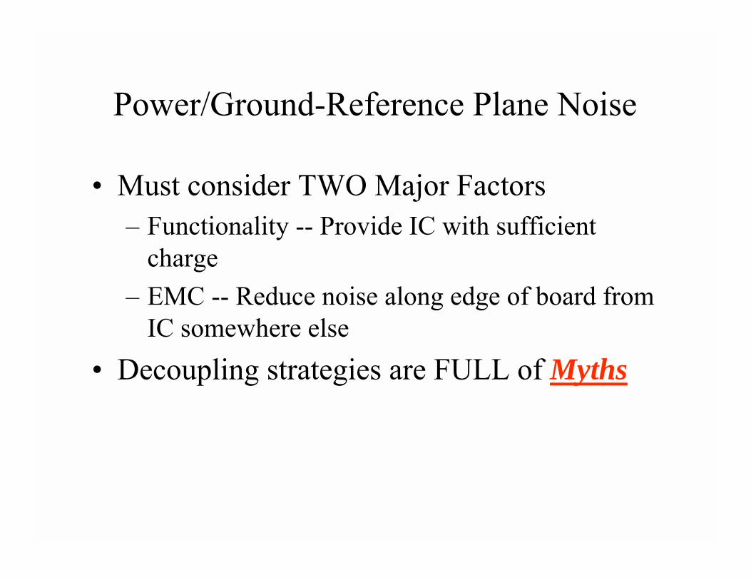
Power/Ground-Reference Plane Noise
• Must consider TWO Major Factors– Functionality -- Provide IC with sufficient
charge– EMC -- Reduce noise along edge of board from
IC somewhere else• Decoupling strategies are FULL of Myths
Source of Power/Ground-Reference Plane Noise
• Power requirements from IC during switching
• Critical Net currents routed through via
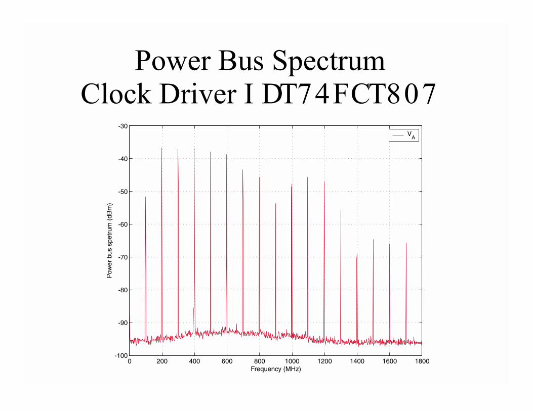
Power Bus SpectrumClock Driver I DT74FCT807
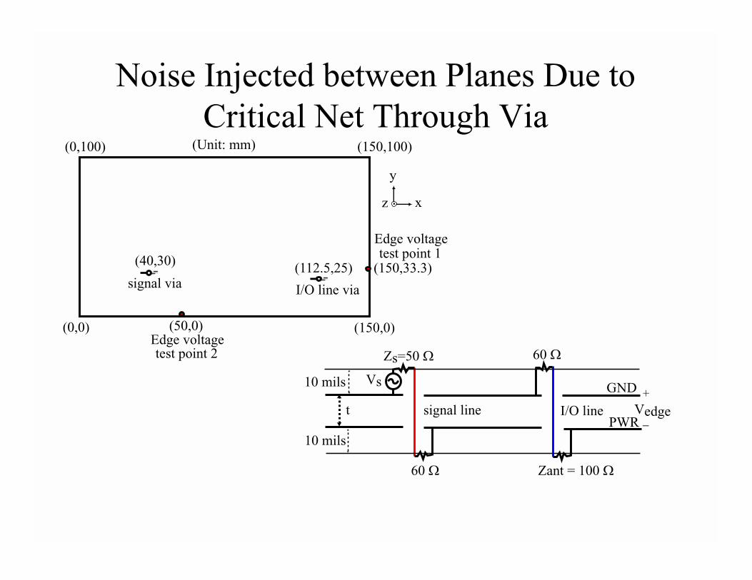
Noise Injected between Planes Due to Critical Net Through Via
(0,0) (150,0)
(0,100) (150,100)
signal viaI/O line via
(Unit: mm)
(40,30)(112.5,25) (150,33.3)
(50,0)Edge voltagetest point 2
Edge voltagetest point 1
xz
y
Zant = 100
60
60
signal line I/O linet
Vs10 mils
10 mils
PWR
GND
Zs=50
_
+
Vedge
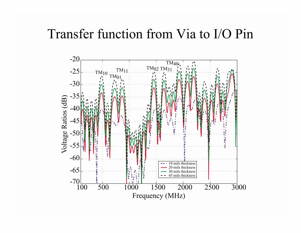
Transfer function from Via to I/O Pin
500 1000 1500 2000 2500 3000-70
-65
-60
-55
-50
-45
-40
-35
-30
-25
-20
Frequency (MHz)
Volt
age R
ati
os
(dB
)
10 mils thickness20 mils thickness30 mils thickness45 mils thickness
100
TM10TM01
TM11TM02 TM31
TM40
Decoupling Must be Analyzed in Different Ways for Different Functions• EMC
– Resonance big concern– Requires STEADY-STATE analysis
• Frequency Domain
– Transfer function analysis• Eliminate noise along edge of board due to ASIC/IC
located far away
Decoupling Must be Analyzed in Different Ways for Different Functions• Provide Charge to ASIC/IC
– Requires TRANSIENT analysis– Charge will NOT travel from far corners of the
board fast enough– Local decoupling capacitors dominate– Impedance at ASIC/IS pins important
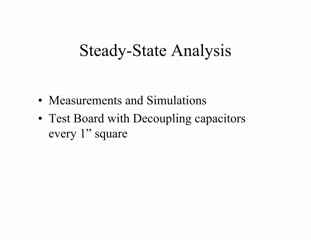
Steady-State Analysis
• Measurements and Simulations• Test Board with Decoupling capacitors
every 1” square
5”
1”
9”10”
1”3”
6”9”
11”12”
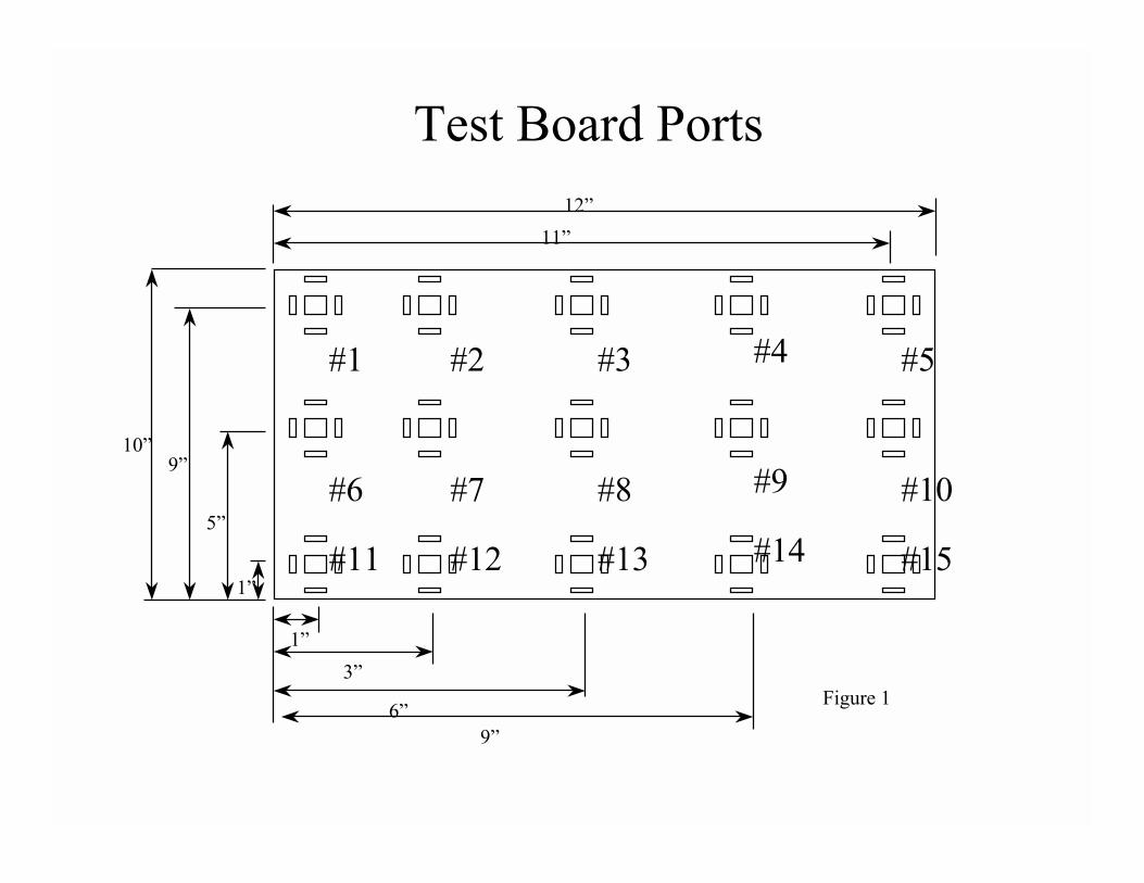
Figure 1
Test Board Ports
#1 #2 #3 #4 #5
#6 #7 #8 #9 #10
#11 #12 #13 #14 #15
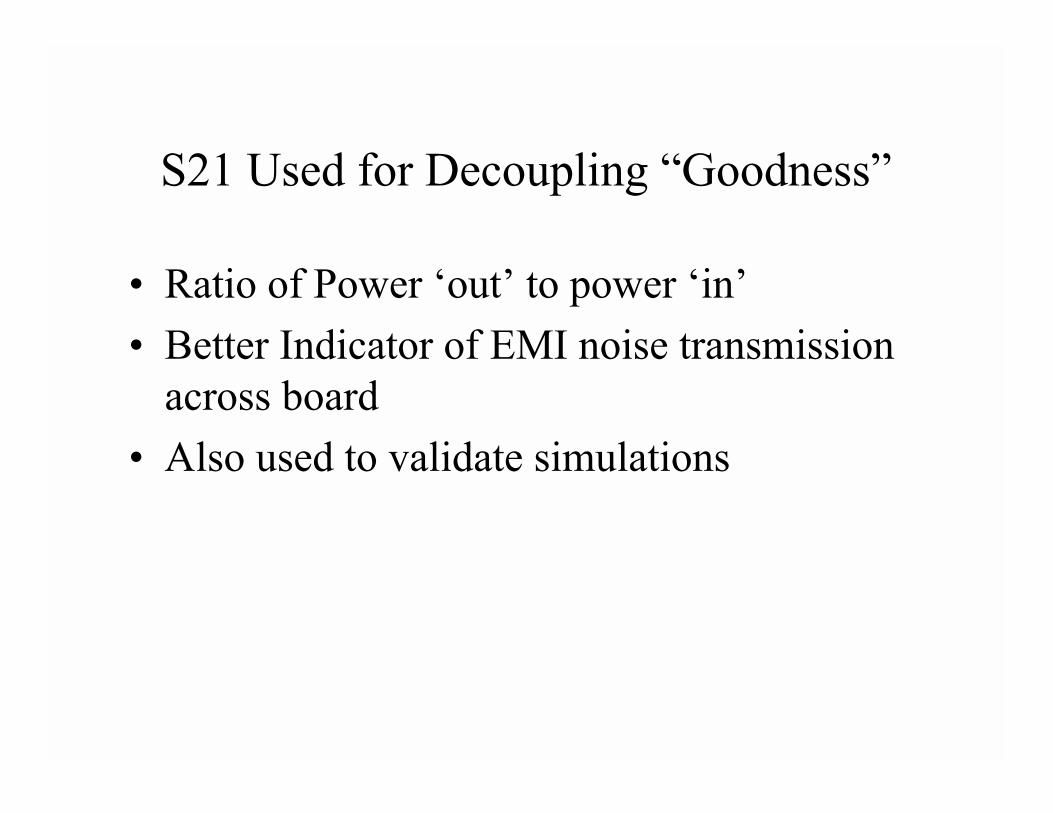
S21 Used for Decoupling “Goodness”
• Ratio of Power ‘out’ to power ‘in’• Better Indicator of EMI noise transmission
across board• Also used to validate simulations
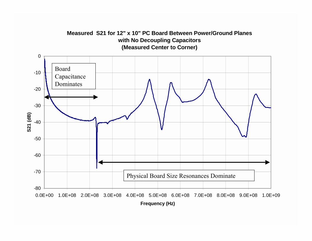
Measured S21 for 12" x 10" PC Board Between Power/Ground Planeswith No Decoupling Capacitors
(Measured Center to Corner)
-80
-70
-60
-50
-40
-30
-20
-10
0
0.0E+00 1.0E+08 2.0E+08 3.0E+08 4.0E+08 5.0E+08 6.0E+08 7.0E+08 8.0E+08 9.0E+08 1.0E+09Frequency (Hz)
S21
(dB
)
Board Capacitance Dominates
Physical Board Size Resonances Dominate
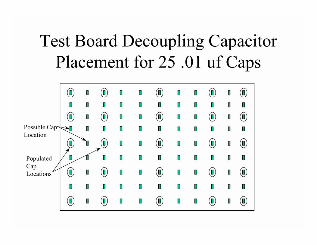
Test Board Decoupling Capacitor Placement for 25 .01 uf Caps
Possible CapLocation
PopulatedCapLocations

Test Board Decoupling Capacitor Placement for 51 .01 uf Caps
Possible CapLocation
PopulatedCapLocations
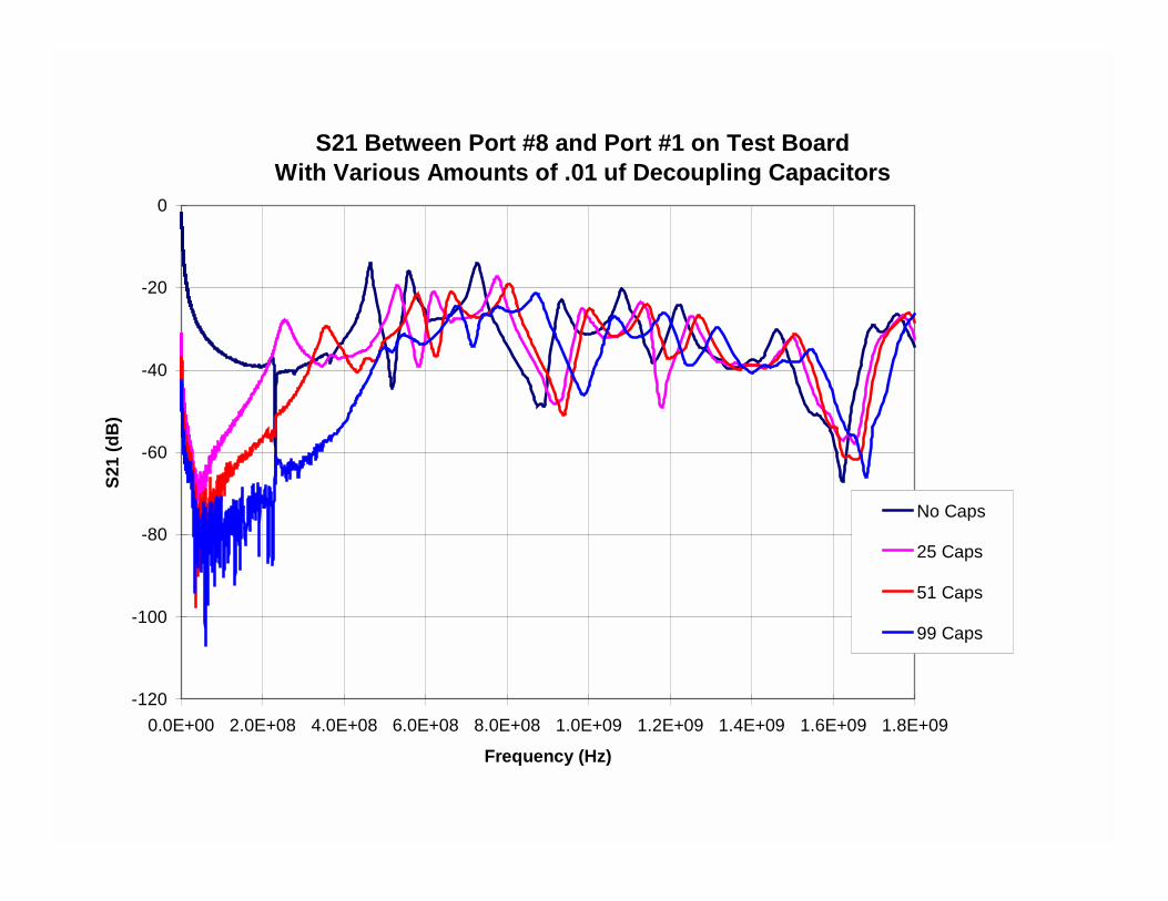
S21 Between Port #8 and Port #1 on Test BoardWith Various Amounts of .01 uf Decoupling Capacitors
-120
-100
-80
-60
-40
-20
0
0.0E+00 2.0E+08 4.0E+08 6.0E+08 8.0E+08 1.0E+09 1.2E+09 1.4E+09 1.6E+09 1.8E+09
Frequency (Hz)
S21
(dB
)
No Caps
25 Caps
51 Caps
99 Caps
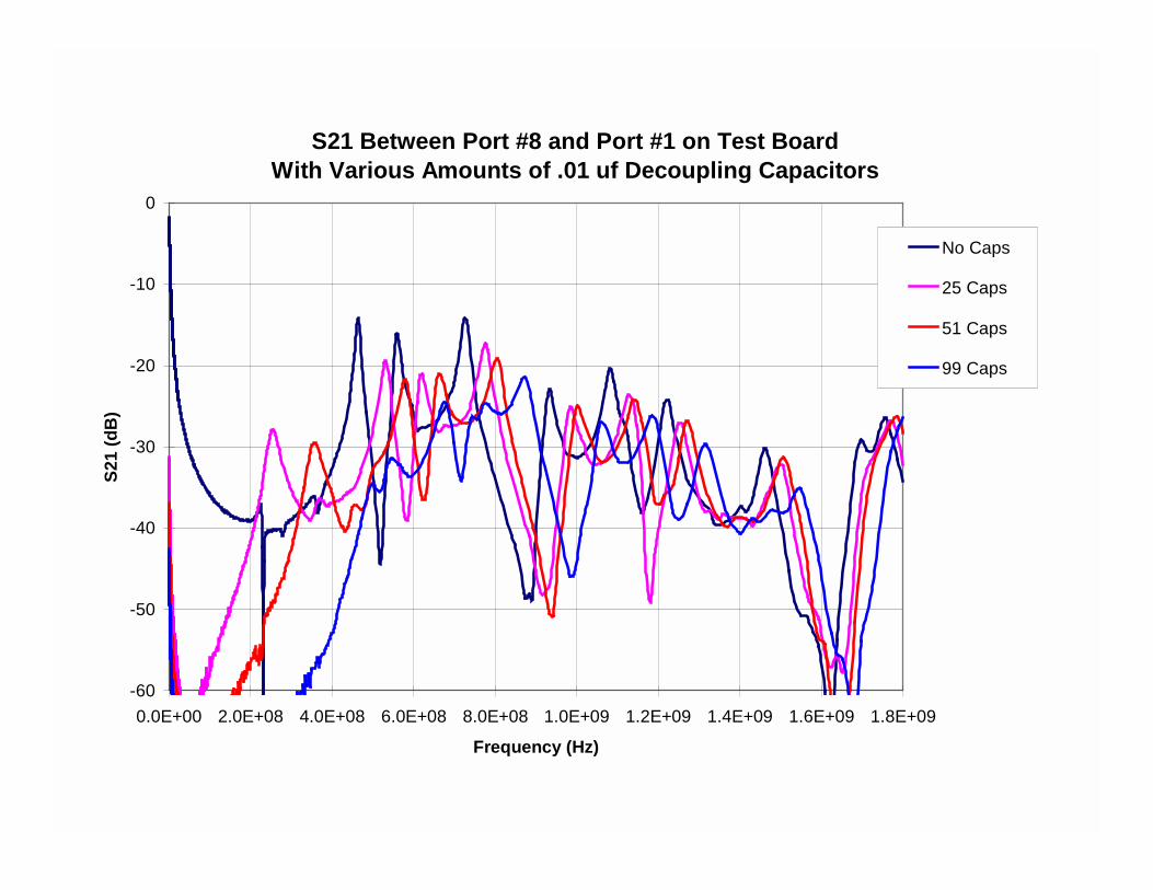
S21 Between Port #8 and Port #1 on Test BoardWith Various Amounts of .01 uf Decoupling Capacitors
-60
-50
-40
-30
-20
-10
0
0.0E+00 2.0E+08 4.0E+08 6.0E+08 8.0E+08 1.0E+09 1.2E+09 1.4E+09 1.6E+09 1.8E+09
Frequency (Hz)
S21
(dB
)
No Caps
25 Caps
51 Caps
99 Caps
1.00E+6 1.00E+7 1.00E+8 1.00E+9 1.00E+10
Freq (Hz)
0.1
1
10
100
1000
10000
|Z| (
Ohm
s)
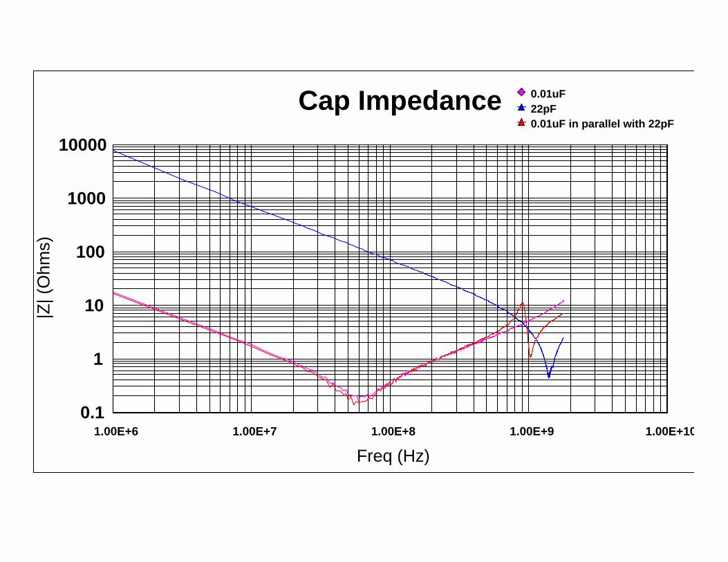
0.01uF22pF0.01uF in parallel with 22pF
Cap Impedance
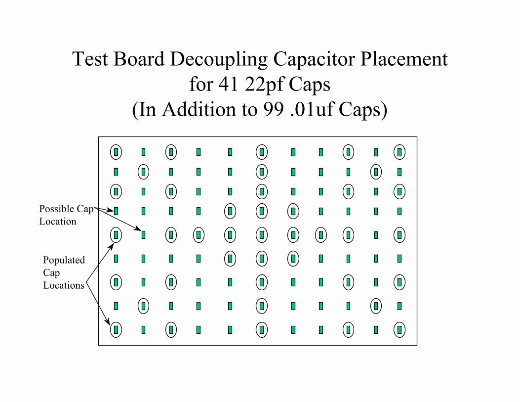
Test Board Decoupling Capacitor Placement for 41 22pf Caps
(In Addition to 99 .01uf Caps)
Possible CapLocation
PopulatedCapLocations
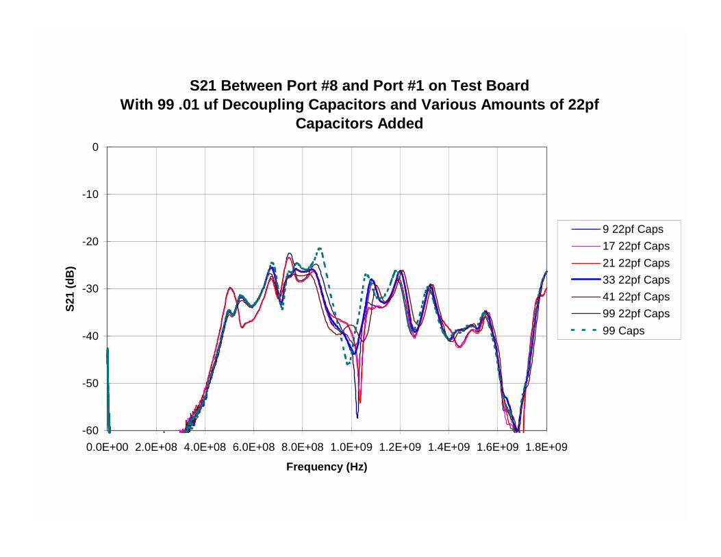
S21 Between Port #8 and Port #1 on Test BoardWith 99 .01 uf Decoupling Capacitors and Various Amounts of 22pf
Capacitors Added
-60
-50
-40
-30
-20
-10
0
0.0E+00 2.0E+08 4.0E+08 6.0E+08 8.0E+08 1.0E+09 1.2E+09 1.4E+09 1.6E+09 1.8E+09
Frequency (Hz)
S21
(dB
)
9 22pf Caps17 22pf Caps21 22pf Caps33 22pf Caps41 22pf Caps99 22pf Caps99 Caps
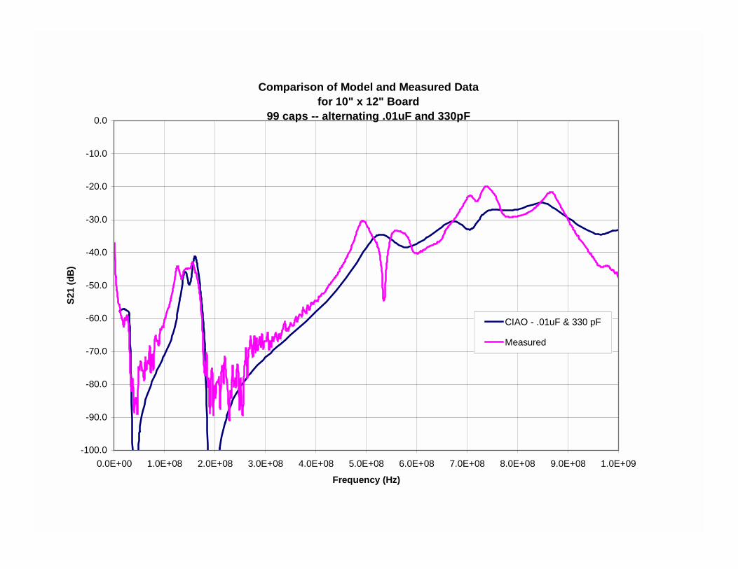
Comparison of Model and Measured Datafor 10" x 12" Board
99 caps -- alternating .01uF and 330pF
-100.0
-90.0
-80.0
-70.0
-60.0
-50.0
-40.0
-30.0
-20.0
-10.0
0.0
0.0E+00 1.0E+08 2.0E+08 3.0E+08 4.0E+08 5.0E+08 6.0E+08 7.0E+08 8.0E+08 9.0E+08 1.0E+09
Frequency (Hz)
S21
(dB
)
CIAO - .01uF & 330 pF
Measured
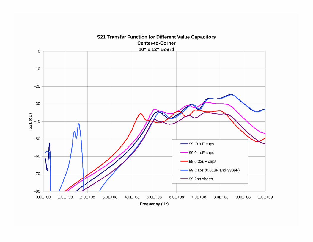
S21 Transfer Function for Different Value CapacitorsCenter-to-Corner10" x 12" Board
-80
-70
-60
-50
-40
-30
-20
-10
0
0.0E+00 1.0E+08 2.0E+08 3.0E+08 4.0E+08 5.0E+08 6.0E+08 7.0E+08 8.0E+08 9.0E+08 1.0E+09
Frequency (Hz)
S21
(dB
)
99 .01uF caps
99 0.1uF caps
99 0.33uF caps
99 Caps (0.01uF and 330pF)
99 2nh shorts
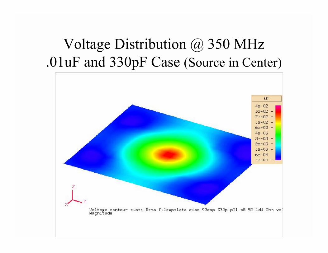
Voltage Distribution @ 350 MHz.01uF and 330pF Case (Source in Center)
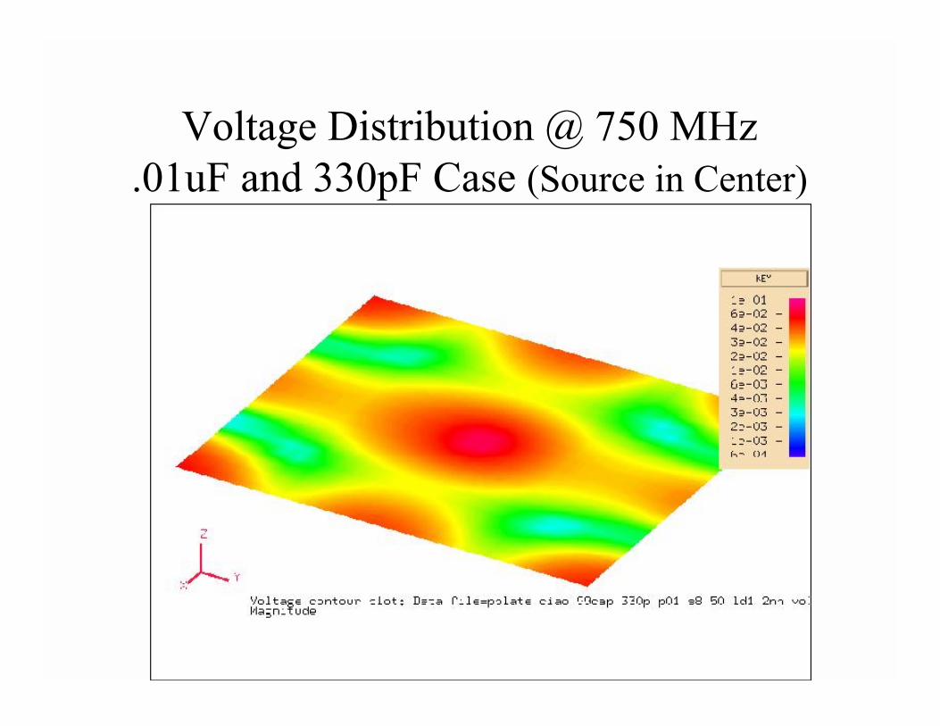
Voltage Distribution @ 750 MHz.01uF and 330pF Case (Source in Center)
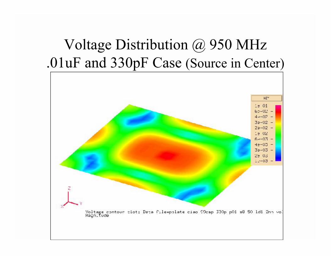
Voltage Distribution @ 950 MHz.01uF and 330pF Case (Source in Center)
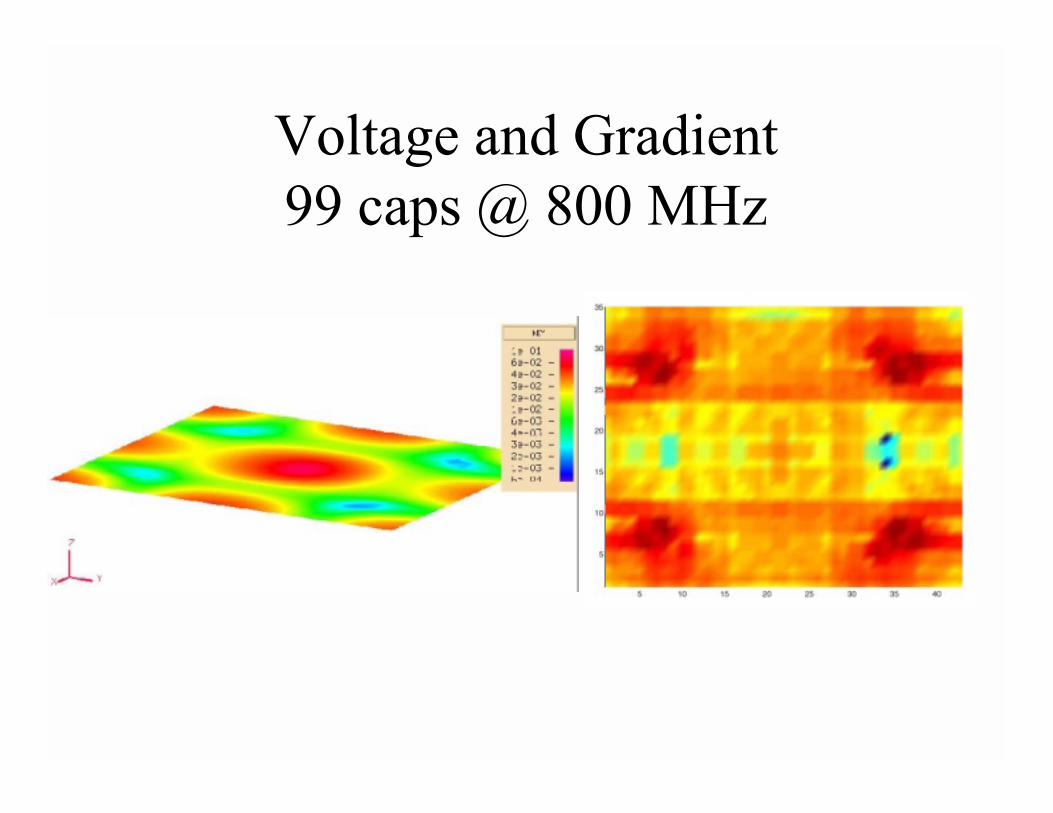
Voltage and Gradient99 caps @ 800 MHz
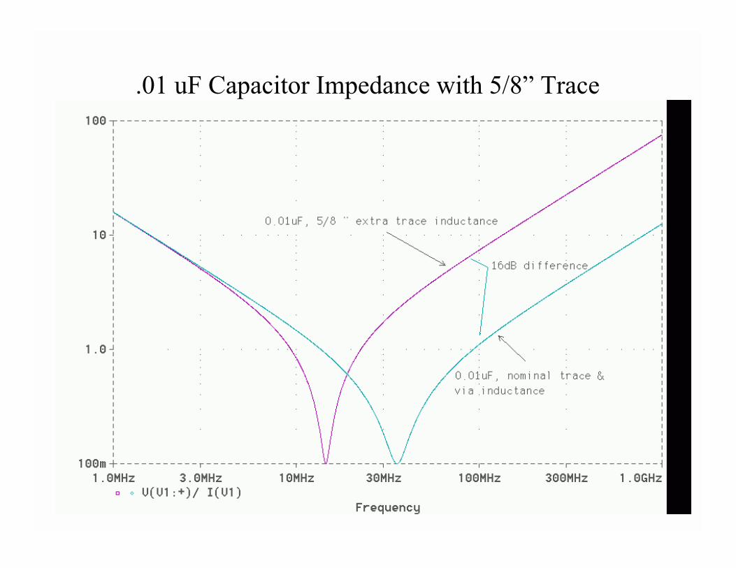
.01 uF Capacitor Impedance with 5/8” Trace
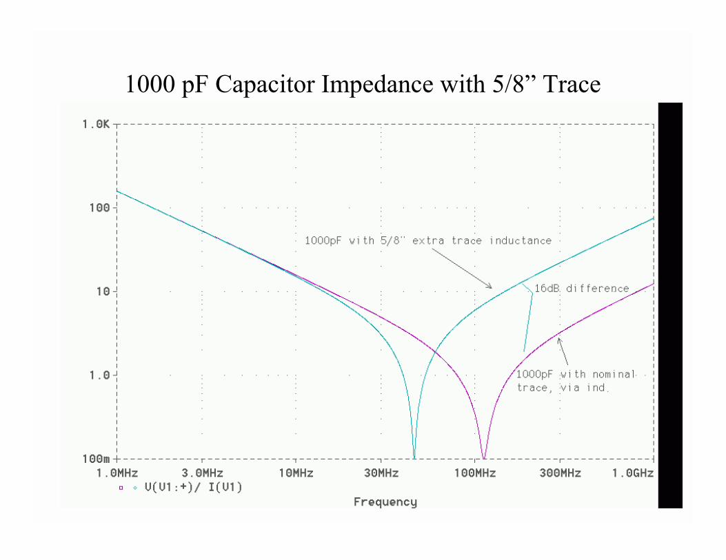
1000 pF Capacitor Impedance with 5/8” Trace
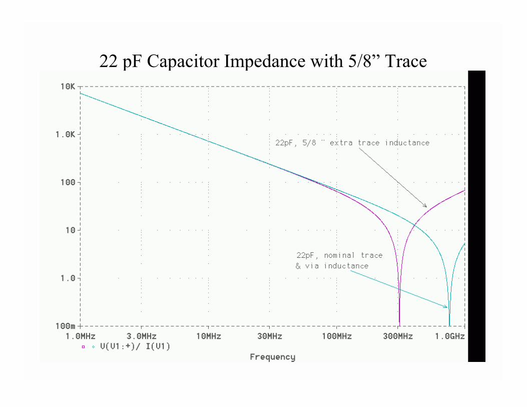
22 pF Capacitor Impedance with 5/8” Trace
Other Design Possibilities
• So-called Buried Capacitance– Reduces high frequency transfer function– Allows less capacitors to be used– Really should be called ‘increased distributed
capacitance’• Lossy decoupling
– Reduces high frequency transfer function– Allows less capacitors to be used
Buried Capacitance
• Planes very close together (2 mils)• Only effective for the power/ground plane
pair !!!• Other sets of Planes must still be decoupled
the traditional way
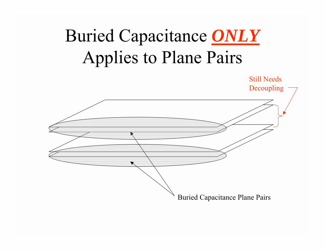
Buried Capacitance ONLYApplies to Plane Pairs
Buried Capacitance Plane Pairs
Still Needs Decoupling
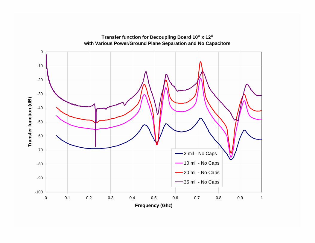
Transfer function for Decoupling Board 10" x 12"with Various Power/Ground Plane Separation and No Capacitors
-100
-90
-80
-70
-60
-50
-40
-30
-20
-10
0
0 0.1 0.2 0.3 0.4 0.5 0.6 0.7 0.8 0.9 1
Frequency (Ghz)
Tran
sfer
func
tion
(dB
)
2 mil - No Caps
10 mil - No Caps
20 mil - No Caps
35 mil - No Caps

Transfer function for Decoupling Board 10" x 12"with Various Power/Ground Plane Separation
-100
-90
-80
-70
-60
-50
-40
-30
-20
-10
0
0 0.1 0.2 0.3 0.4 0.5 0.6 0.7 0.8 0.9 1
Frequency (Ghz)
Tran
sfer
func
tion
(dB
)
2 mil - No Caps
10 mil - No Caps
20 mil - No Caps
35 mil - No Caps
35 mil w/99 caps
Lossy Decoupling
• New technique• Series resistance and capacitance in same
SMT package• Need to use both low ESR capacitors and
lossy capacitors– fewer total parts
Cause of Failure above400 - 500 MHz?
• Inductance is limiting factor for capacitors• Board size cause resonances which causes
problems• Need to reduce resonance effects by
lowering Q-factor– add resistive loss
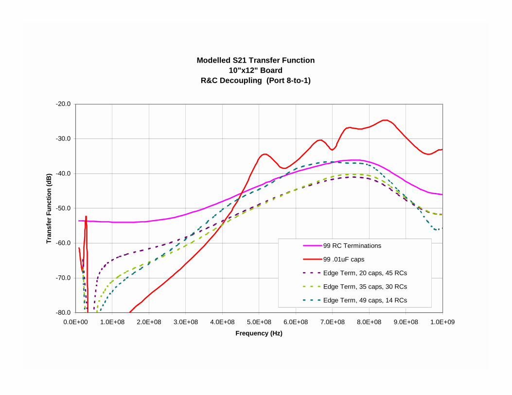
Modelled S21 Transfer Function10"x12" Board
R&C Decoupling (Port 8-to-1)
-80.0
-70.0
-60.0
-50.0
-40.0
-30.0
-20.0
0.0E+00 1.0E+08 2.0E+08 3.0E+08 4.0E+08 5.0E+08 6.0E+08 7.0E+08 8.0E+08 9.0E+08 1.0E+09
Frequency (Hz)
Tran
sfer
Fun
ctio
n (d
B)
99 RC Terminations
99 .01uF caps
Edge Term, 20 caps, 45 RCs
Edge Term, 35 caps, 30 RCs
Edge Term, 49 caps, 14 RCs
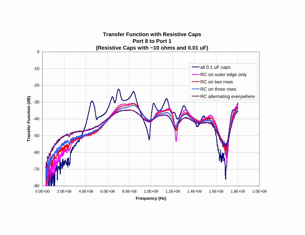
Transfer Function with Resistive CapsPort 8 to Port 1
(Resistive Caps with ~10 ohms and 0.01 uF)
-80
-70
-60
-50
-40
-30
-20
-10
0
0.0E+00 2.0E+08 4.0E+08 6.0E+08 8.0E+08 1.0E+09 1.2E+09 1.4E+09 1.6E+09 1.8E+09 2.0E+09
Frequency (Hz)
Tran
sfer
Fun
ctio
n (d
B)
all 0.1 uF capsRC on outer edge onlyRC on two rowsRC on three rowsRC alternating everywhere
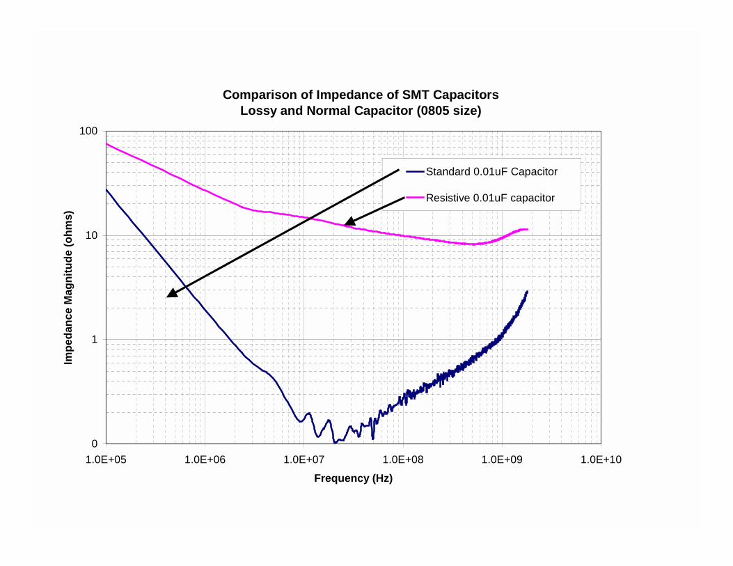
Comparison of Impedance of SMT CapacitorsLossy and Normal Capacitor (0805 size)
0
1
10
100
1.0E+05 1.0E+06 1.0E+07 1.0E+08 1.0E+09 1.0E+10
Frequency (Hz)
Impe
danc
e M
agni
tude
(ohm
s)
Standard 0.01uF Capacitor
Resistive 0.01uF capacitor
Transient Analysis
• Provide charge to ASIC/IC• Inductance dominates impedance
– Loop area 1st order effect• Traditional analysis not accurate enough
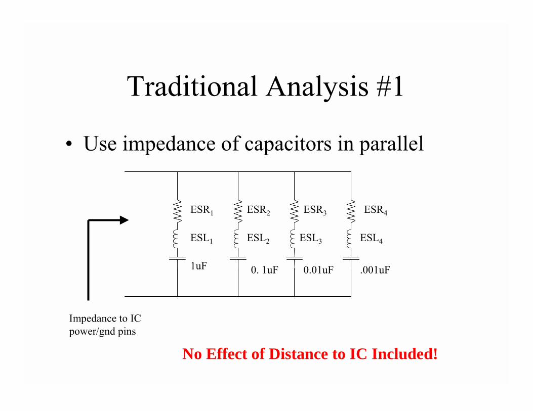
Traditional Analysis #1
• Use impedance of capacitors in parallel
Impedance to IC power/gnd pins
ESR1 ESR4ESR3ESR2
ESL1 ESL4ESL3ESL2
1uF .001uF0.01uF0. 1uF
No Effect of Distance to IC Included!
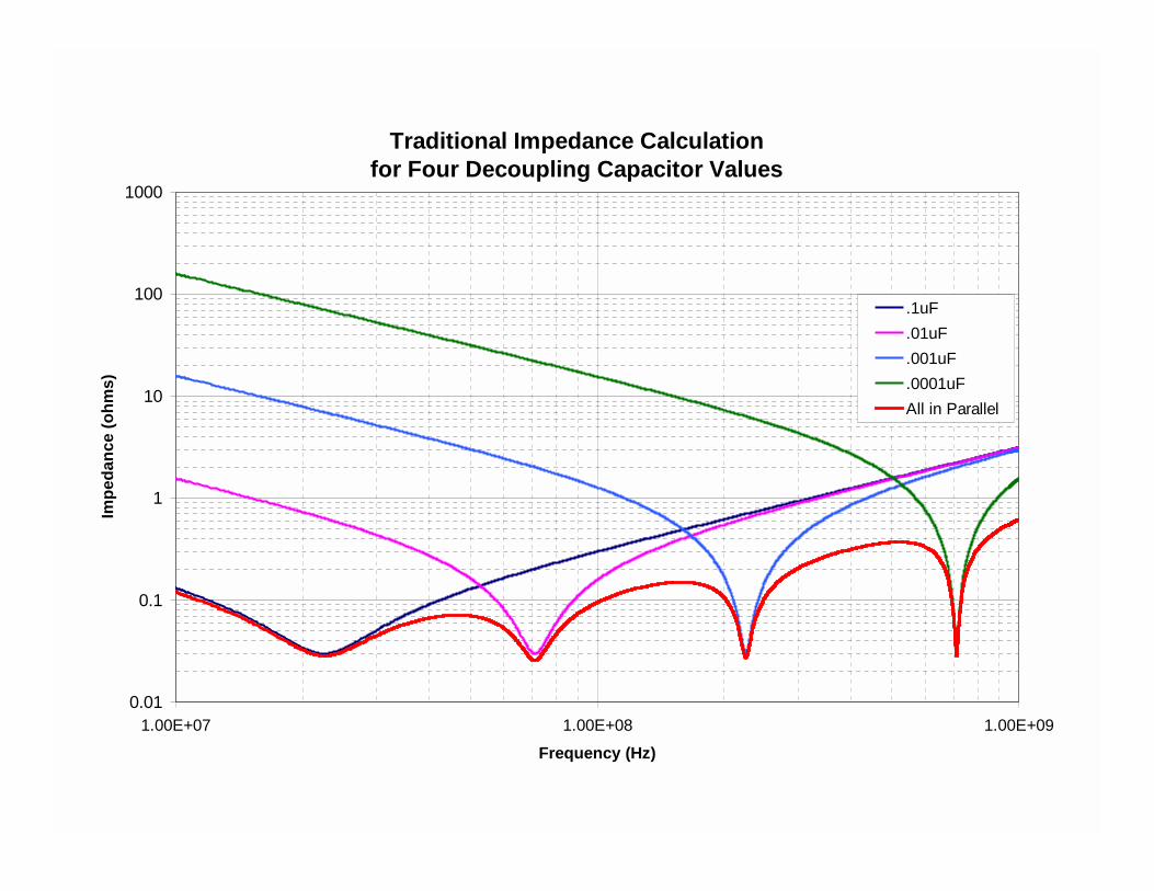
Traditional Impedance Calculation for Four Decoupling Capacitor Values
0.01
0.1
1
10
100
1000
1.00E+07 1.00E+08 1.00E+09
Frequency (Hz)
Impe
danc
e (o
hms)
.1uF
.01uF
.001uF
.0001uFAll in Parallel
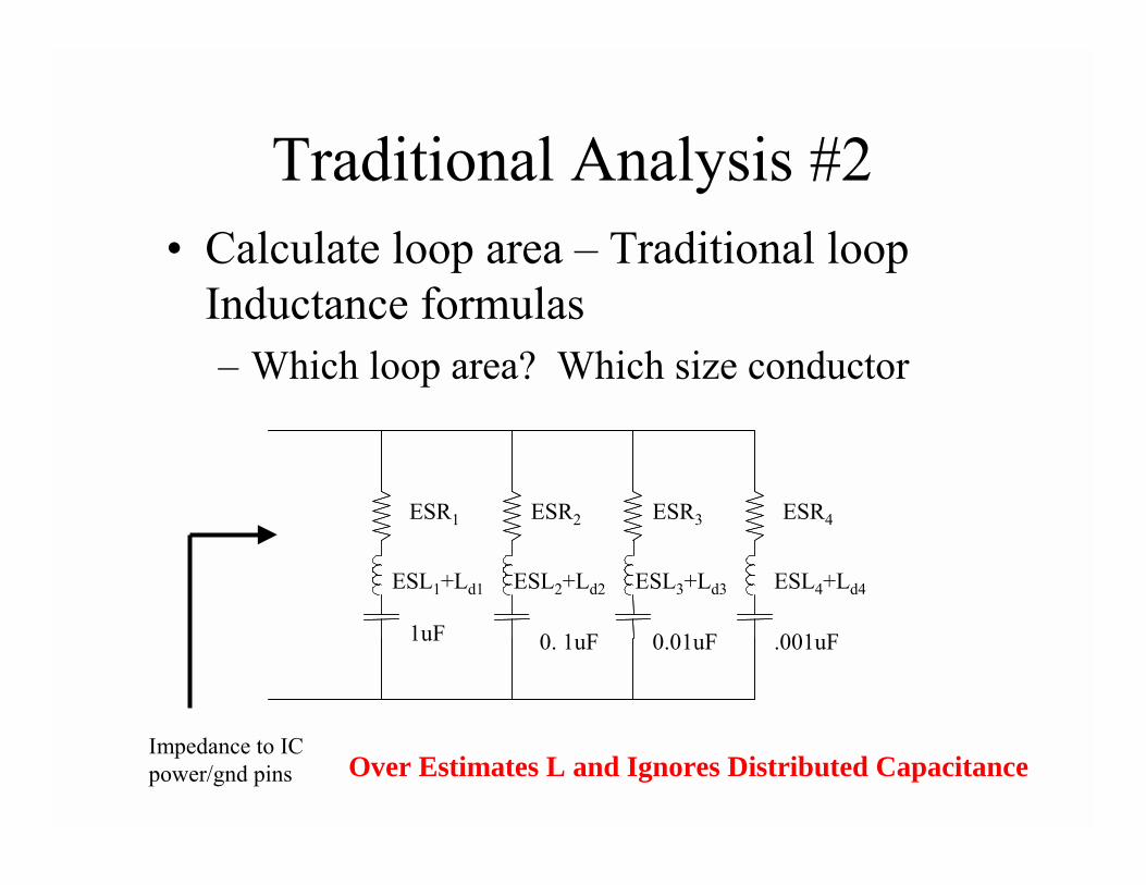
Traditional Analysis #2• Calculate loop area – Traditional loop
Inductance formulas– Which loop area? Which size conductor
Impedance to IC power/gnd pins
ESR1 ESR4ESR3ESR2
ESL1+Ld1
1uF .001uF0.01uF0. 1uF
ESL2+Ld2 ESL3+Ld3 ESL4+Ld4
Over Estimates L and Ignores Distributed Capacitance
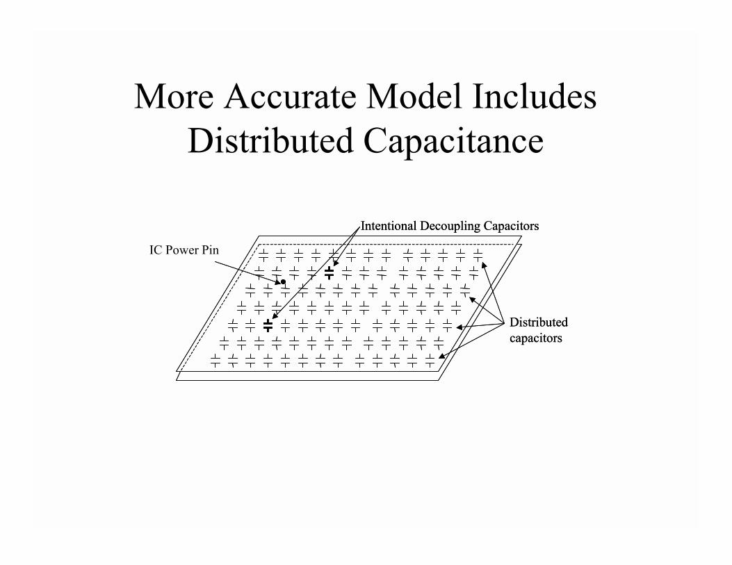
More Accurate Model Includes Distributed Capacitance
Distributed capacitors
Intentional Decoupling Capacitors
Distributed capacitors
IC Power Pin
Intentional Decoupling Capacitors
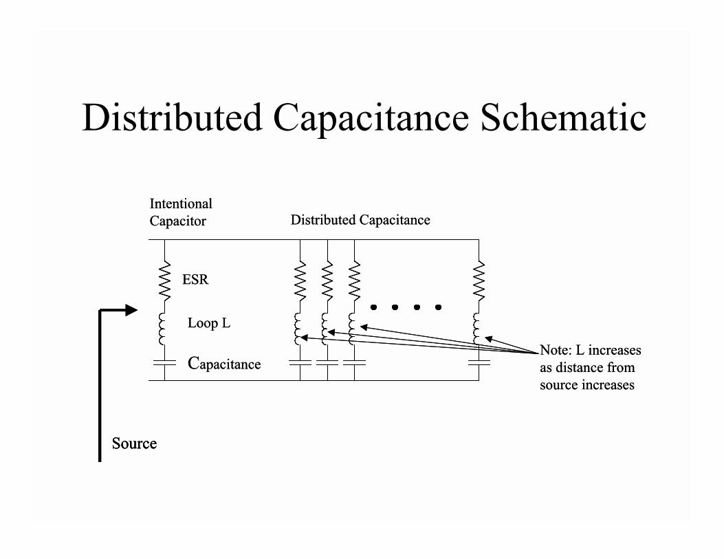
Distributed Capacitance Schematic
Loop L
Capacitance
ESR
Distributed CapacitanceIntentional Capacitor
Source
Note: L increases as distance from source increases
Loop L
Capacitance
ESR
Distributed CapacitanceIntentional Capacitor
SourceSource
Note: L increases as distance from source increases
Effect of Distributed Capacitance
• Can NOT be calculated/estimated using traditional capacitance equation
• Displacement current amplitude changes with position and distance from the source
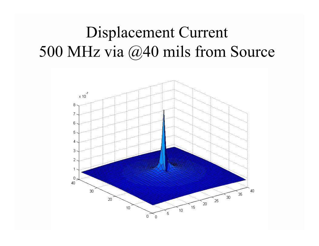
Displacement Current 500 MHz via @40 mils from Source
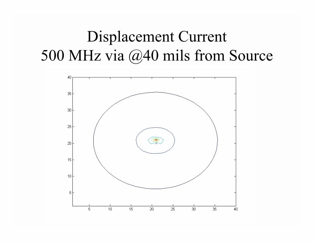
Displacement Current 500 MHz via @40 mils from Source

Displacement Current 500 MHz via @450 mils from Source
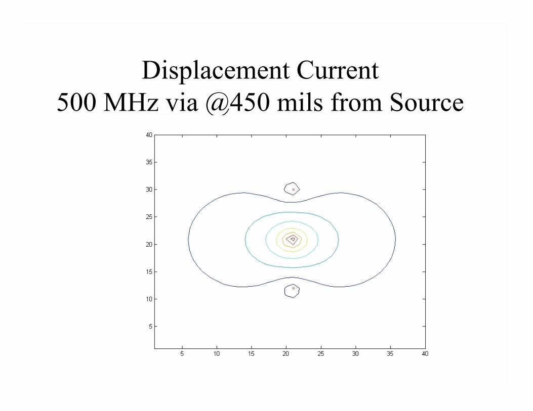
Displacement Current 500 MHz via @450 mils from Source
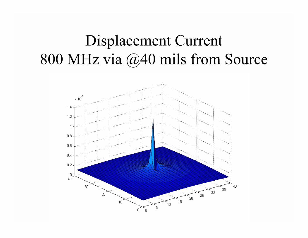
Displacement Current 800 MHz via @40 mils from Source
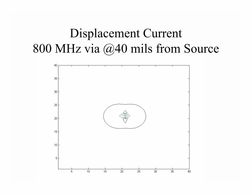
Displacement Current 800 MHz via @40 mils from Source
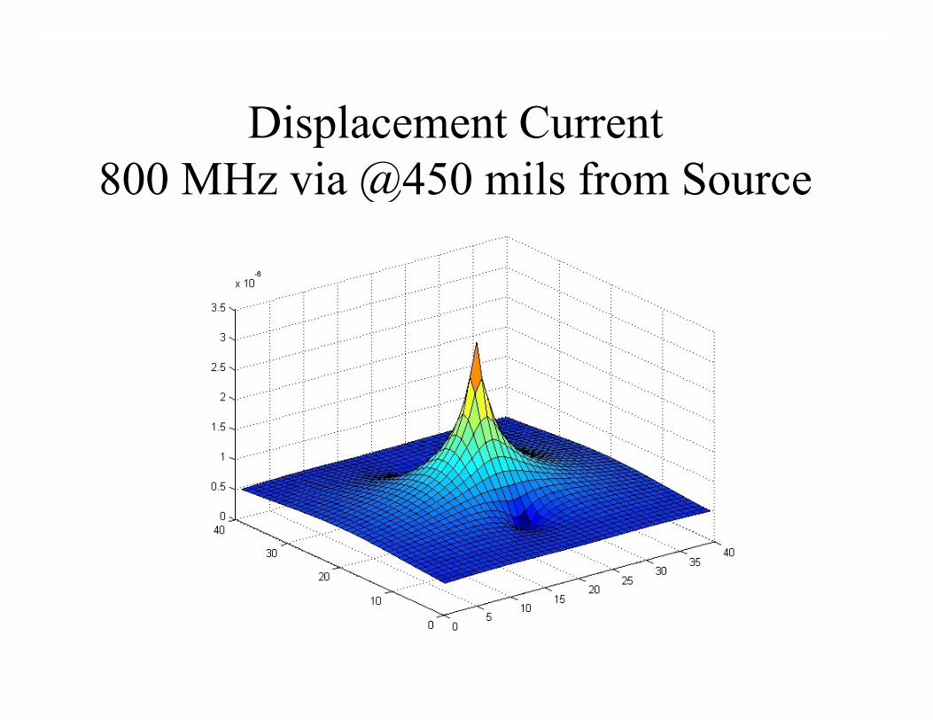
Displacement Current 800 MHz via @450 mils from Source
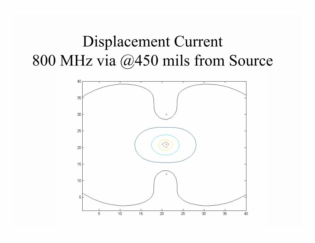
Displacement Current 800 MHz via @450 mils from Source
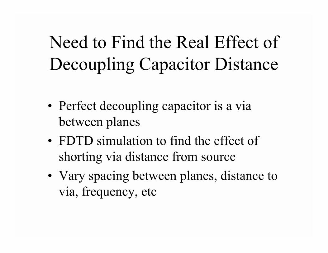
Need to Find the Real Effect of Decoupling Capacitor Distance
• Perfect decoupling capacitor is a via between planes
• FDTD simulation to find the effect of shorting via distance from source
• Vary spacing between planes, distance to via, frequency, etc
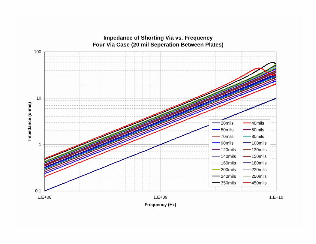
Impedance of Shorting Via vs. Frequency Four Via Case (20 mil Seperation Between Plates)
0.1
1
10
100
1.E+08 1.E+09 1.E+10Frequency (Hz)
Impe
danc
e (o
hms)
20mils 40mils50mils 60mils70mils 80mils90mils 100mils120mils 130mils140mils 150mils160mils 180mils200mils 220mils240mils 250mils350mils 450mils
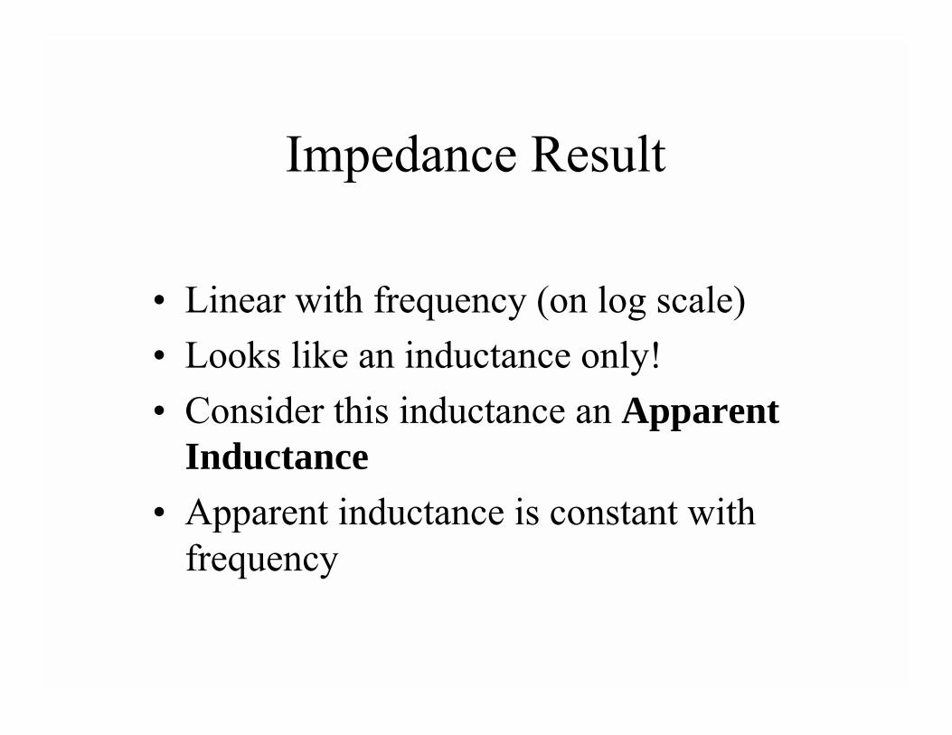
Impedance Result
• Linear with frequency (on log scale)• Looks like an inductance only!• Consider this inductance an Apparent
Inductance• Apparent inductance is constant with
frequency
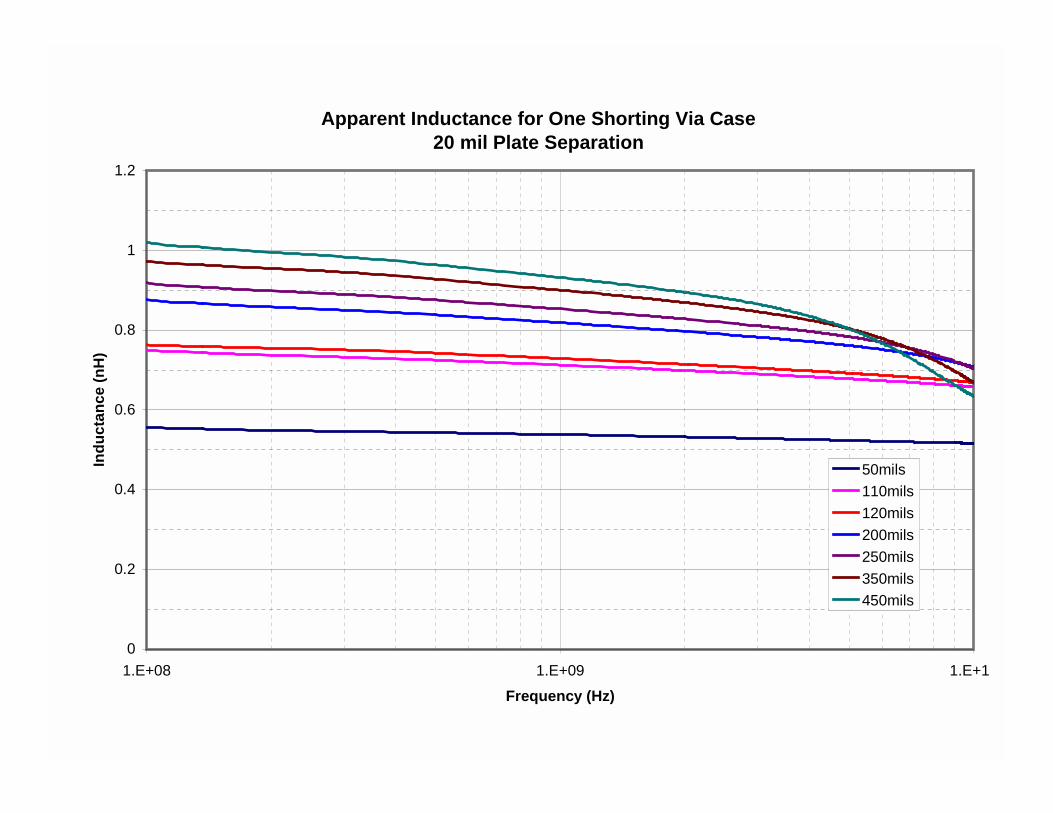
Apparent Inductance for One Shorting Via Case20 mil Plate Separation
0
0.2
0.4
0.6
0.8
1
1.2
1.E+08 1.E+09 1.E+1Frequency (Hz)
Indu
ctan
ce (n
H)
50mils110mils120mils200mils250mils350mils450mils
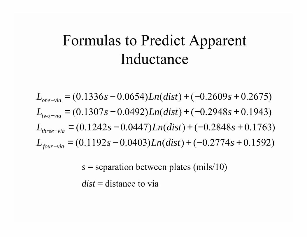
Formulas to Predict Apparent Inductance
)1592.02774.0()()0403.01192.0()1763.02848.0()()0447.01242.0(
)1943.02948.0()()0492.01307.0()2675.02609.0()()0654.01336.0(
+−+−=+−+−=
+−+−=+−+−=
−
−
−
−
sdistLnsLsdistLnsL
sdistLnsLsdistLnsL
viafour
viathree
viatwo
viaone
s = separation between plates (mils/10)
dist = distance to via
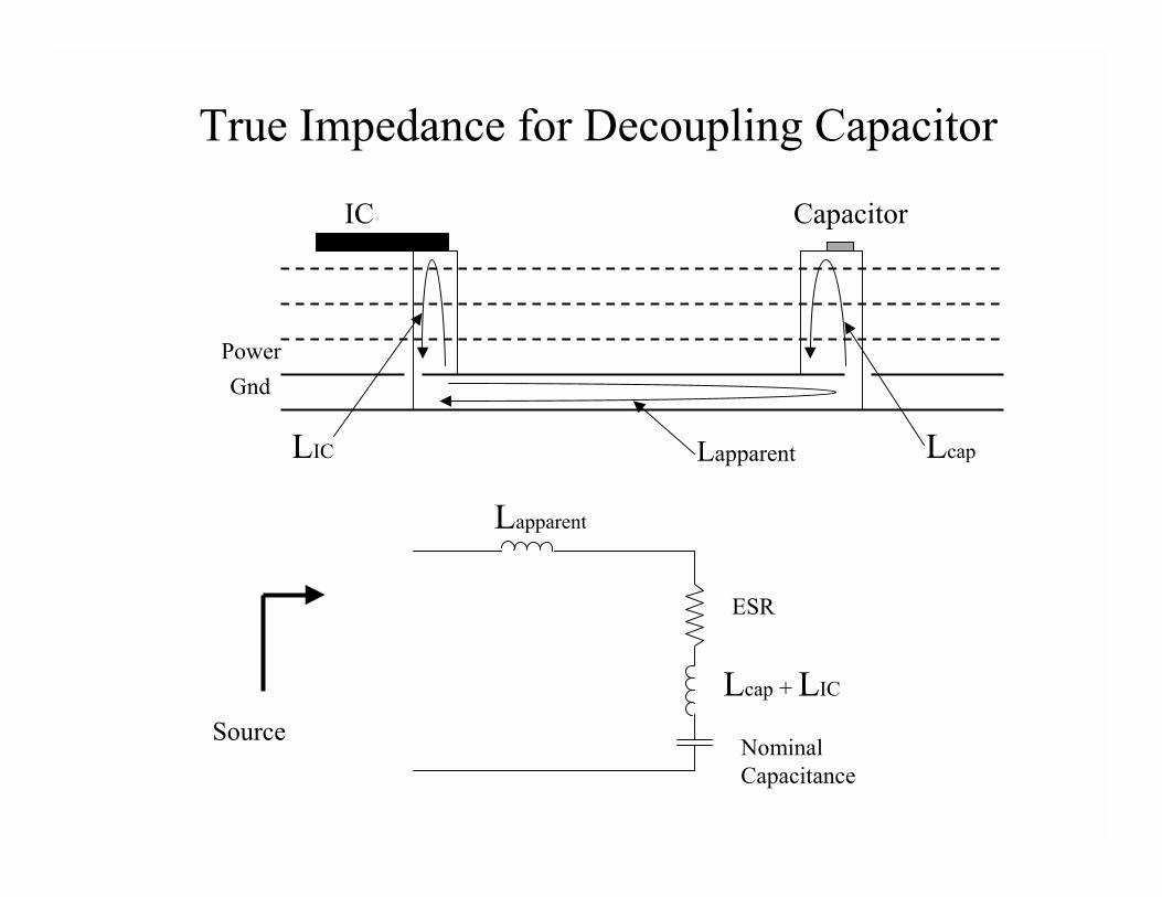
LapparentLIC Lcap
IC Capacitor
PowerGnd
ESR
Lcap + LIC
Nominal Capacitance
Lapparent
Source
True Impedance for Decoupling Capacitor
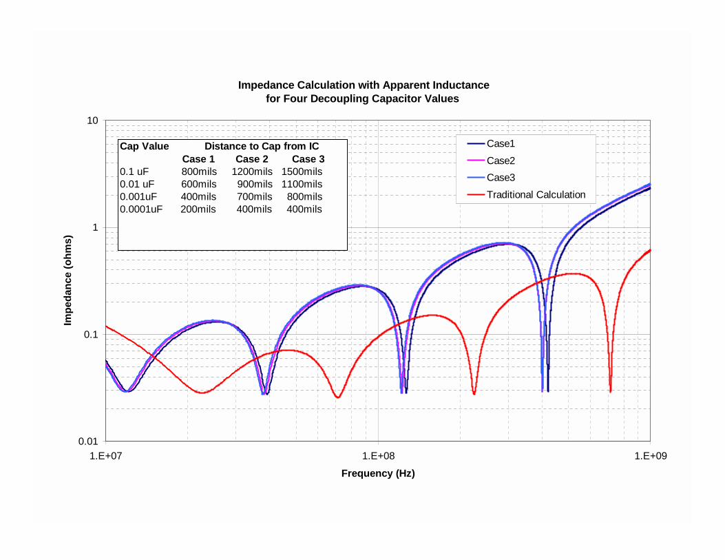
Impedance Calculation with Apparent Inductancefor Four Decoupling Capacitor Values
0.01
0.1
1
10
1.E+07 1.E+08 1.E+09
Frequency (Hz)
Impe
danc
e (o
hms)
Case1Case2Case3Traditional Calculation
Cap Value Distance to Cap from IC Case 1 Case 2 Case 30.1 uF 800mils 1200mils 1500mils0.01 uF 600mils 900mils 1100mils0.001uF 400mils 700mils 800mils0.0001uF 200mils 400mils 400mils
Two Major Questions
• How will structure respond?• What is the source of the noise?
– CURRENT!
Predicting the Source of Decoupling Noise
• What is the source?• ICs need two types of current
– Current for the I/O drivers– “core” current
• current that does not go out the I/O drivers
• On-going research with Prof Jim Drewniak at UMR
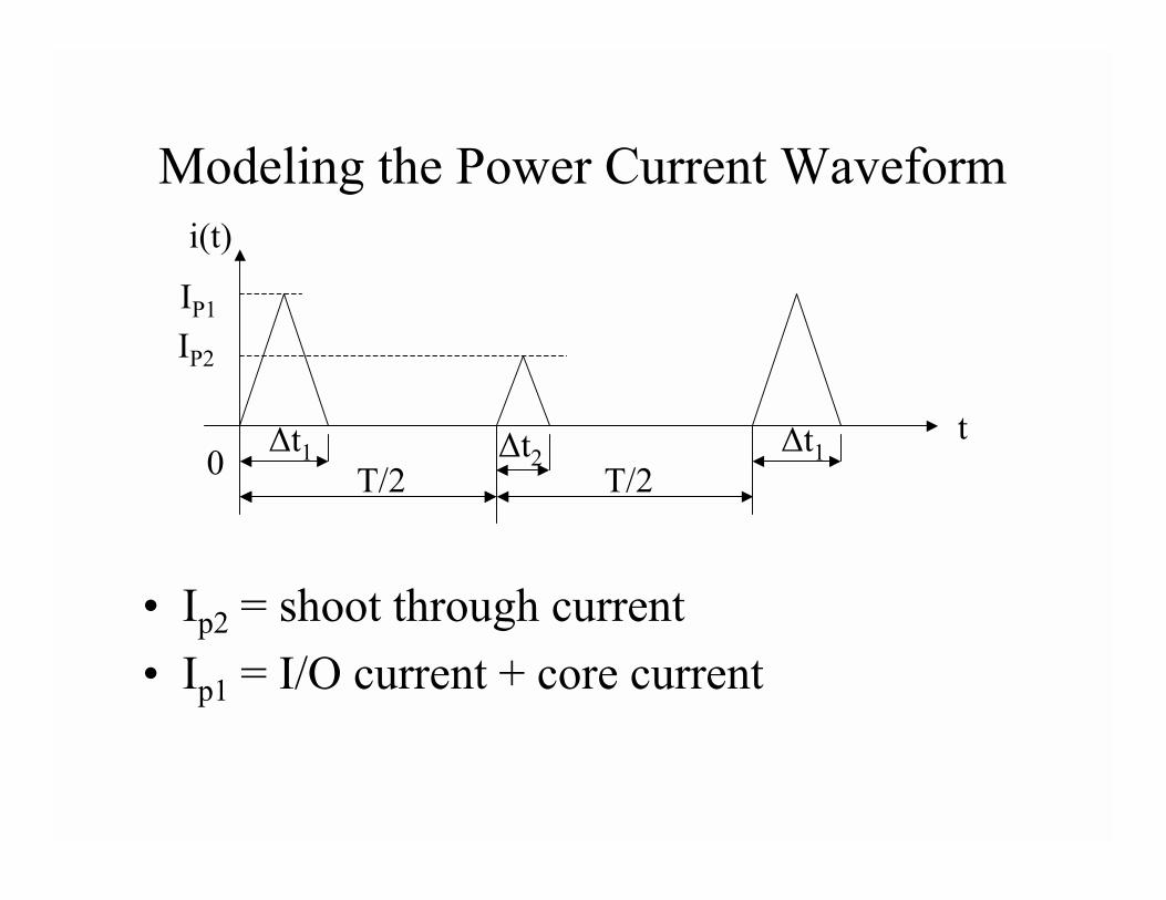
Modeling the Power Current Waveform
• Ip2 = shoot through current• Ip1 = I/O current + core current
∆t1T/2
∆t2T/2
∆t1t
0
i(t)
IP1
IP2
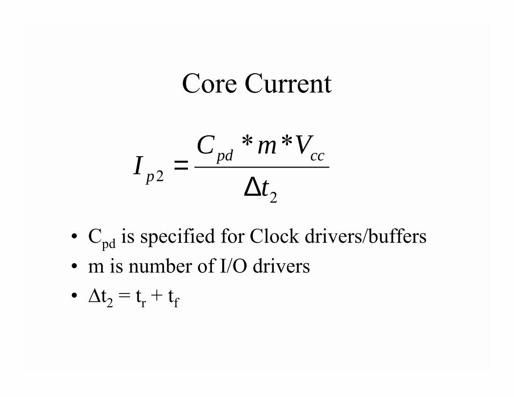
Core Current
• Cpd is specified for Clock drivers/buffers• m is number of I/O drivers• ✁t2 = tr + tf
22
**t
VmCI ccpd
p ∆=
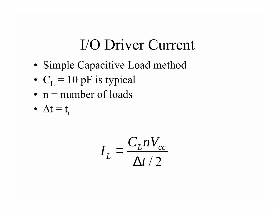
I/O Driver Current• Simple Capacitive Load method• CL = 10 pF is typical• n = number of loads• ✁t = tr
2/tnVCI ccL
L ∆=
More Accurate I/O Driver Current
• Use Signal Integrity tools to find current waveform– Hyperlynx– Spectraquest– SPICE
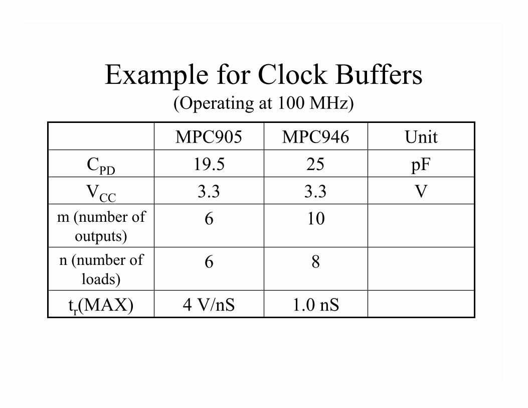
Example for Clock Buffers(Operating at 100 MHz)
VpF
Unit
1.0 nS4 V/nStr(MAX)
86n (number of loads)
106m (number of outputs)
3.33.3VCC
2519.5CPD
MPC946MPC905
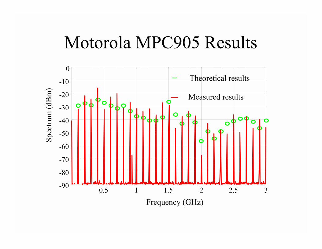
Motorola MPC905 Results
0.5 1 1.5 2 2.5 3-90
-80
-70
-60
-50
-40
-30
-20
-10
0
Frequency (GHz)
Spec
trum
(dB
m)
Measured results
Theoretical results
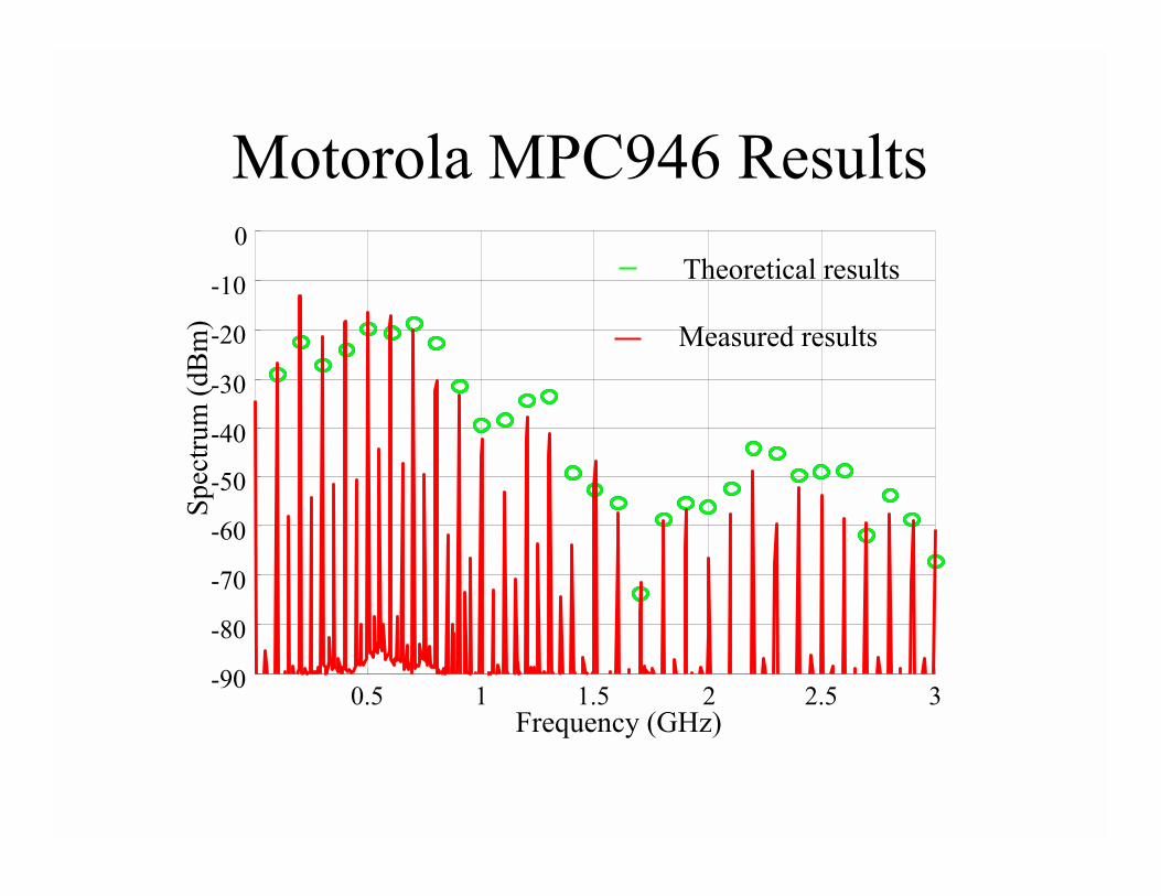
Motorola MPC946 Results
0.5 1 1.5 2 2.5 3-90
-80
-70
-60
-50
-40
-30
-20
-10
0
Frequency (GHz)
Spec
trum
(dB
m) Measured results
Theoretical results
Sources on Active Board
• Large ASICs do not specify Cpd
• Measured power/ground plane noise for large ASIC with and without decoupling capacitors installed
• Circuits operating with exerciser software• Examples for 1.5 volt and 2.5 volt supplies
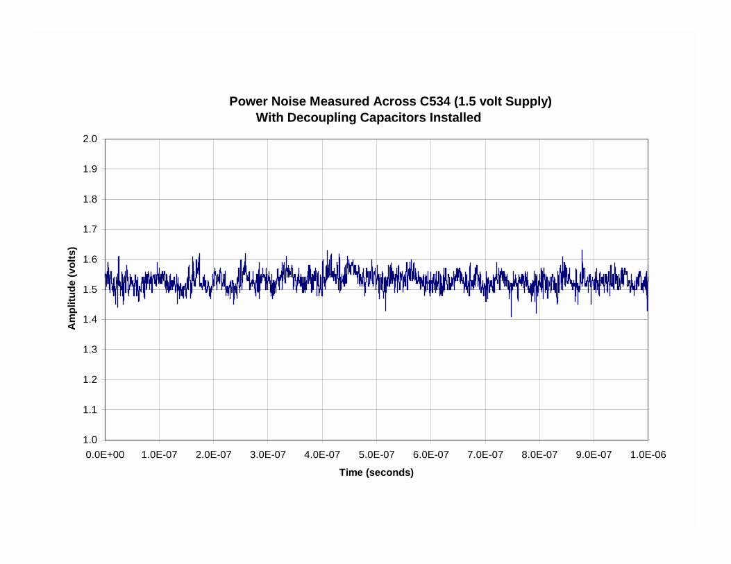
Illinois Power Noise Measured Across C534 (1.5 volt Supply)With Decoupling Capacitors Installed
1.0
1.1
1.2
1.3
1.4
1.5
1.6
1.7
1.8
1.9
2.0
0.0E+00 1.0E-07 2.0E-07 3.0E-07 4.0E-07 5.0E-07 6.0E-07 7.0E-07 8.0E-07 9.0E-07 1.0E-06
Time (seconds)
Am
plitu
de (v
olts
)
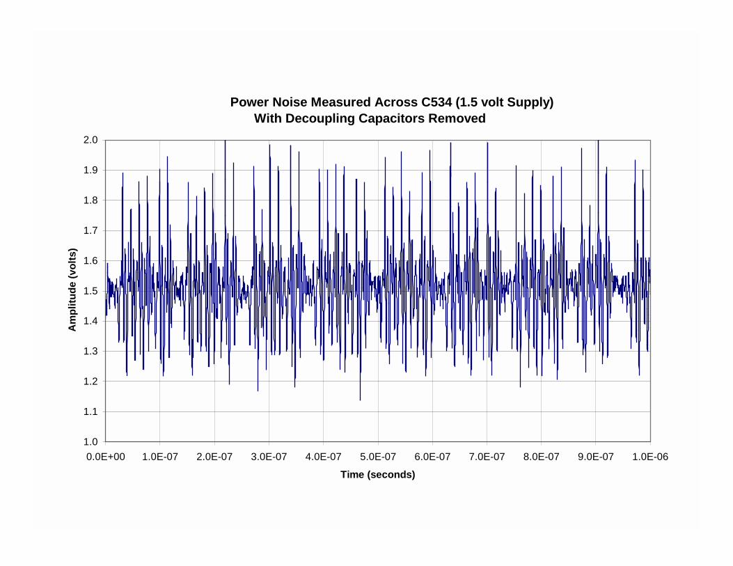
Illinois Power Noise Measured Across C534 (1.5 volt Supply)With Decoupling Capacitors Removed
1.0
1.1
1.2
1.3
1.4
1.5
1.6
1.7
1.8
1.9
2.0
0.0E+00 1.0E-07 2.0E-07 3.0E-07 4.0E-07 5.0E-07 6.0E-07 7.0E-07 8.0E-07 9.0E-07 1.0E-06
Time (seconds)
Am
plitu
de (v
olts
)
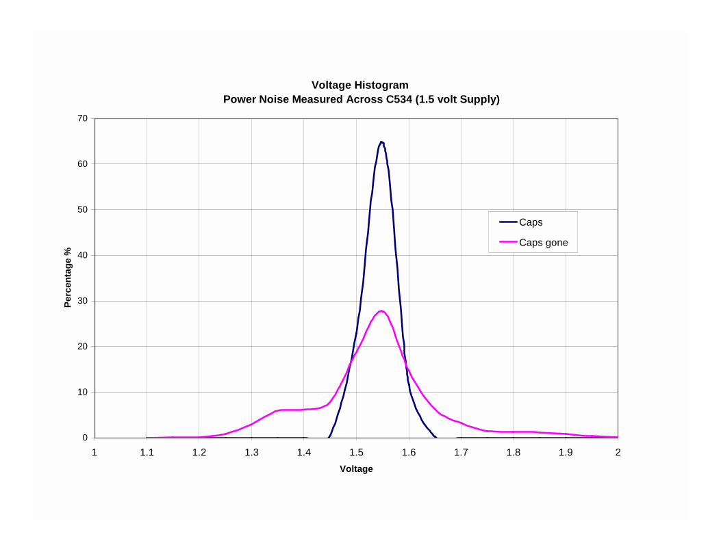
Voltage Histogram Power Noise Measured Across C534 (1.5 volt Supply)
0
10
20
30
40
50
60
70
1 1.1 1.2 1.3 1.4 1.5 1.6 1.7 1.8 1.9 2Voltage
Perc
enta
ge %
Caps
Caps gone
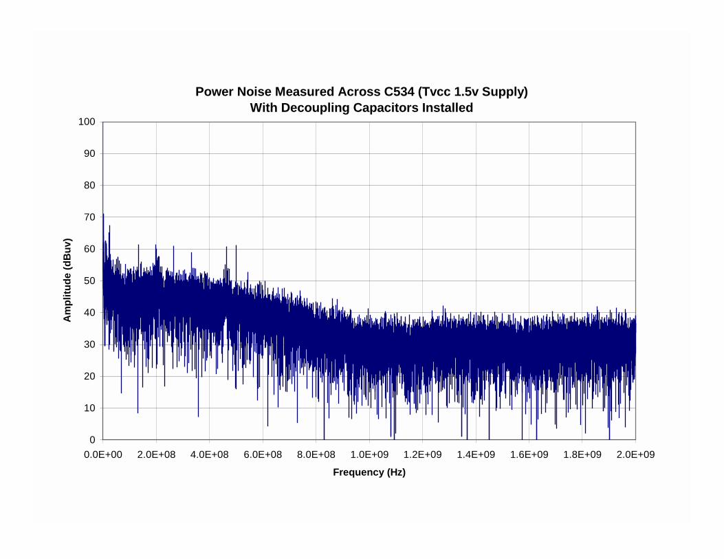
Power Noise Measured Across C534 (Tvcc 1.5v Supply)With Decoupling Capacitors Installed
0
10
20
30
40
50
60
70
80
90
100
0.0E+00 2.0E+08 4.0E+08 6.0E+08 8.0E+08 1.0E+09 1.2E+09 1.4E+09 1.6E+09 1.8E+09 2.0E+09
Frequency (Hz)
Am
plitu
de (d
Buv
)
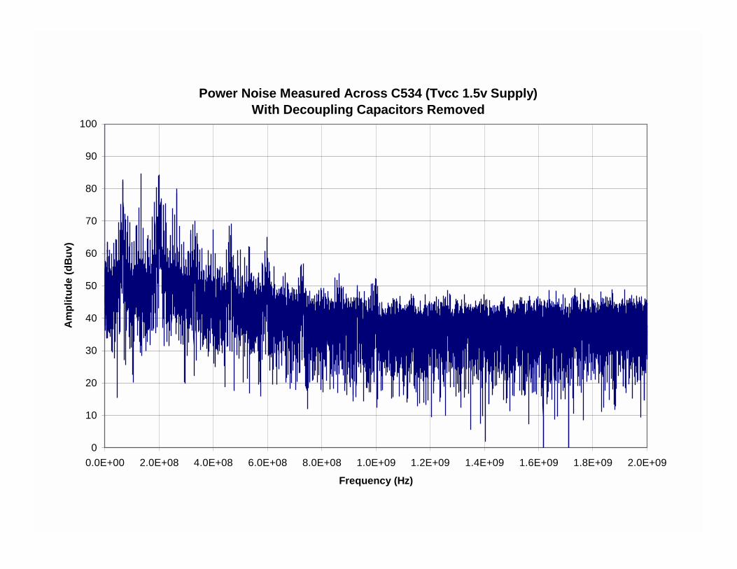
Power Noise Measured Across C534 (Tvcc 1.5v Supply)With Decoupling Capacitors Removed
0
10
20
30
40
50
60
70
80
90
100
0.0E+00 2.0E+08 4.0E+08 6.0E+08 8.0E+08 1.0E+09 1.2E+09 1.4E+09 1.6E+09 1.8E+09 2.0E+09
Frequency (Hz)
Am
plitu
de (d
Buv
)
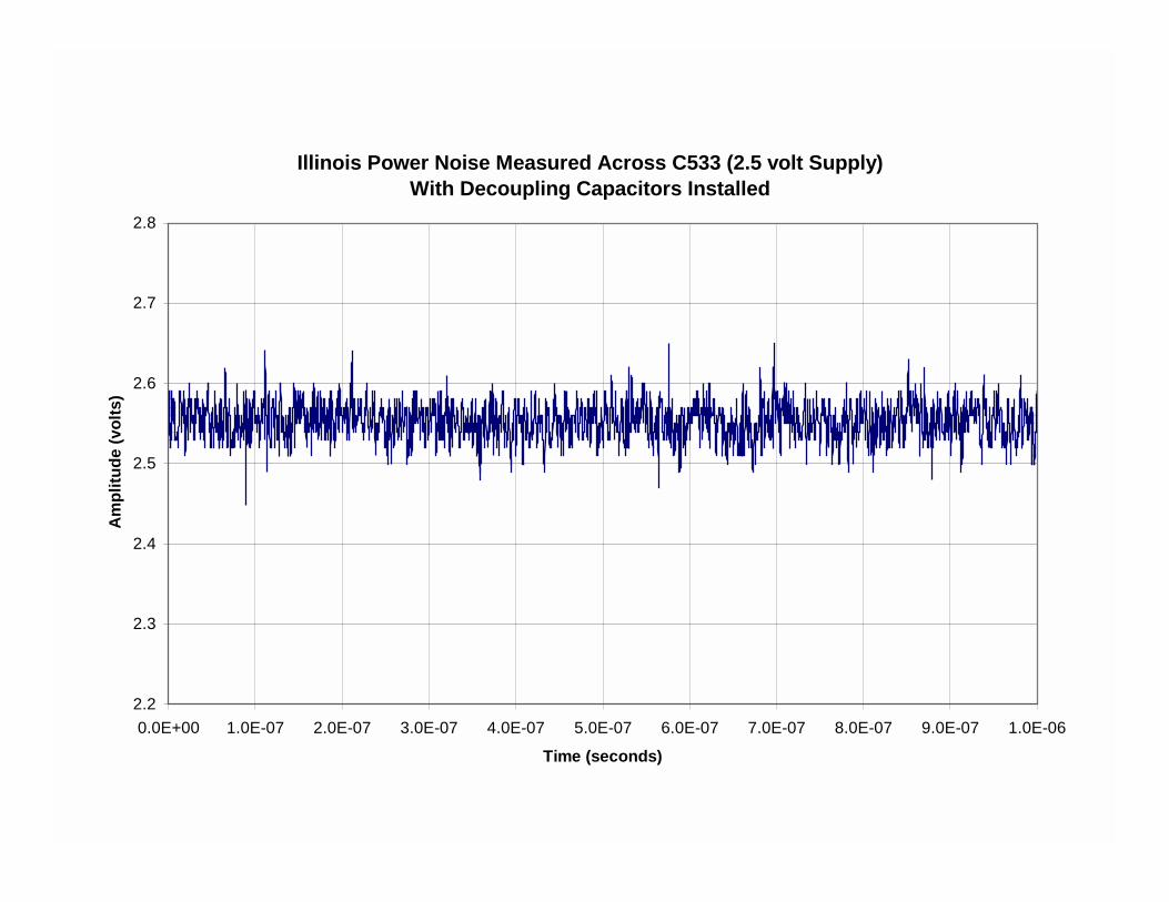
Illinois Power Noise Measured Across C533 (2.5 volt Supply)With Decoupling Capacitors Installed
2.2
2.3
2.4
2.5
2.6
2.7
2.8
0.0E+00 1.0E-07 2.0E-07 3.0E-07 4.0E-07 5.0E-07 6.0E-07 7.0E-07 8.0E-07 9.0E-07 1.0E-06
Time (seconds)
Am
plitu
de (v
olts
)
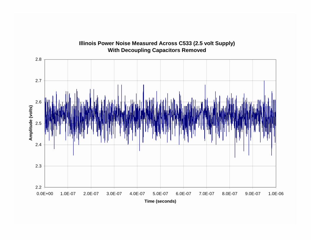
Illinois Power Noise Measured Across C533 (2.5 volt Supply)With Decoupling Capacitors Removed
2.2
2.3
2.4
2.5
2.6
2.7
2.8
0.0E+00 1.0E-07 2.0E-07 3.0E-07 4.0E-07 5.0E-07 6.0E-07 7.0E-07 8.0E-07 9.0E-07 1.0E-06
Time (seconds)
Am
plitu
de (v
olts
)
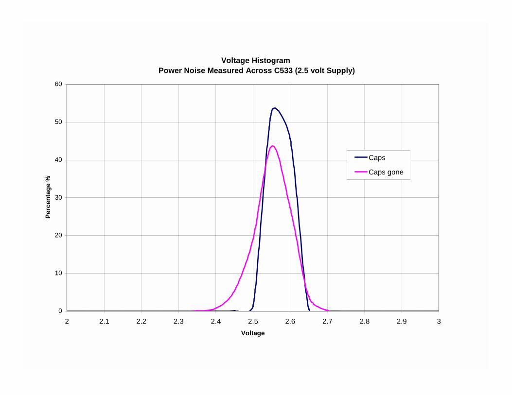
Voltage Histogram Power Noise Measured Across C533 (2.5 volt Supply)
0
10
20
30
40
50
60
2 2.1 2.2 2.3 2.4 2.5 2.6 2.7 2.8 2.9 3Voltage
Perc
enta
ge %
Caps
Caps gone
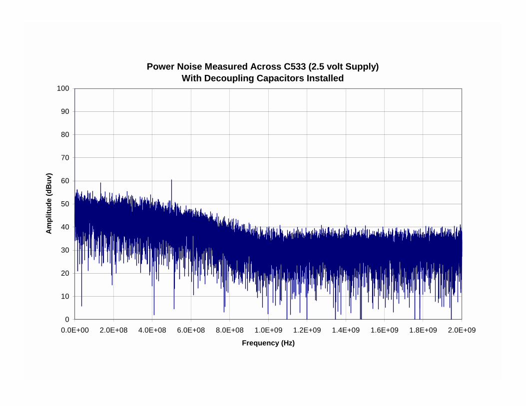
Power Noise Measured Across C533 (2.5 volt Supply)With Decoupling Capacitors Installed
0
10
20
30
40
50
60
70
80
90
100
0.0E+00 2.0E+08 4.0E+08 6.0E+08 8.0E+08 1.0E+09 1.2E+09 1.4E+09 1.6E+09 1.8E+09 2.0E+09
Frequency (Hz)
Am
plitu
de (d
Buv
)
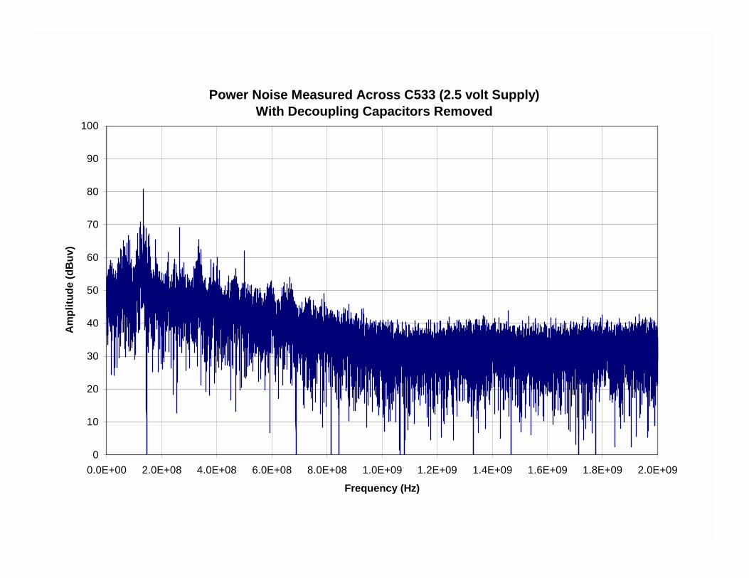
Power Noise Measured Across C533 (2.5 volt Supply)With Decoupling Capacitors Removed
0
10
20
30
40
50
60
70
80
90
100
0.0E+00 2.0E+08 4.0E+08 6.0E+08 8.0E+08 1.0E+09 1.2E+09 1.4E+09 1.6E+09 1.8E+09 2.0E+09
Frequency (Hz)
Am
plitu
de (d
Buv
)
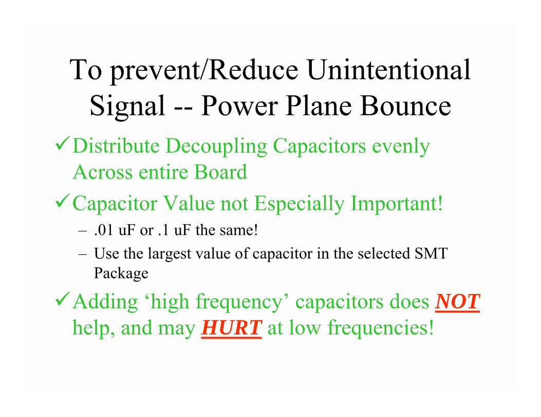
To prevent/Reduce Unintentional Signal -- Power Plane Bounce
�Distribute Decoupling Capacitors evenly Across entire Board
�Capacitor Value not Especially Important!– .01 uF or .1 uF the same!– Use the largest value of capacitor in the selected SMT
Package
�Adding ‘high frequency’ capacitors does NOThelp, and may HURT at low frequencies!
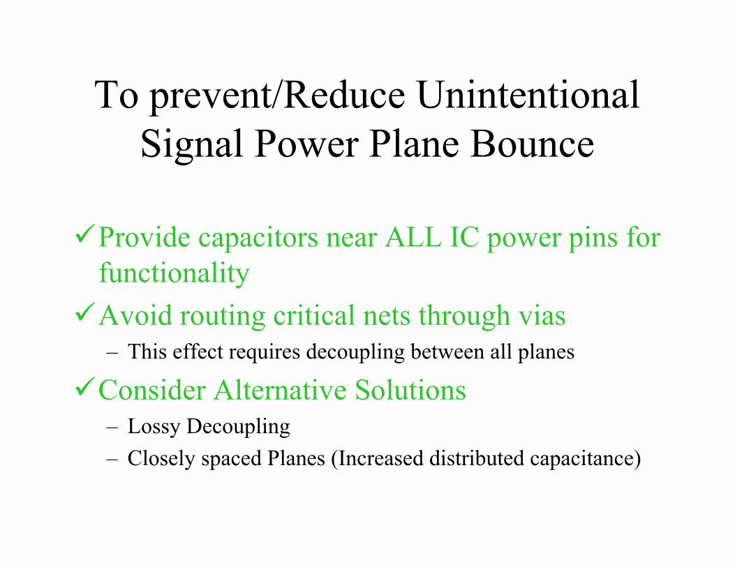
To prevent/Reduce Unintentional Signal Power Plane Bounce
�Provide capacitors near ALL IC power pins for functionality
�Avoid routing critical nets through vias– This effect requires decoupling between all planes
�Consider Alternative Solutions– Lossy Decoupling– Closely spaced Planes (Increased distributed capacitance)
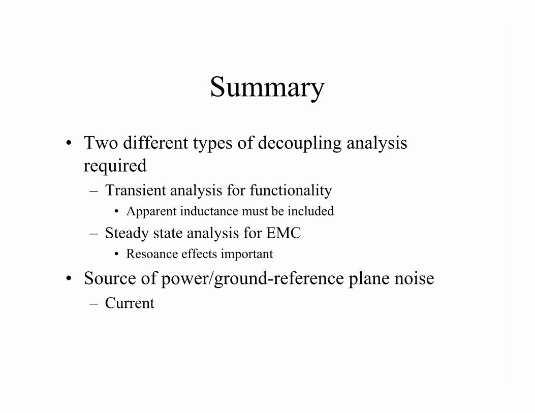
Summary
• Two different types of decoupling analysis required– Transient analysis for functionality
• Apparent inductance must be included
– Steady state analysis for EMC• Resoance effects important
• Source of power/ground-reference plane noise– Current