dynamic positioning conference...
TRANSCRIPT
DYNAMIC POSITIONING CONFERENCE
September 16-17, 2003
FPSOs and Shuttle Tankers
What Dynamic Positioning Means to Floating Storage and
Shuttle Tankers in the Gulf of Mexico
Ernst A. Meyer DNV Consulting USA Inc., Houston
And
Øystein Huglen Navion AS, Stavanger

Øystein Huglen FPSOs and Shuttle Tankers: What DP Means to Floating Storage and Ernst A. Meyer Shuttle Tankers for Operation in GoM
DP Conference, Houston September 16-17, 2003 Page 2
1. Introduction As the oil companies stretch the exploration in the Gulf of Mexico (GoM) to deeper and more remote areas, the present technology, especially the traditional export systems, may not be the preferred solution for these challenges. Current method for crude oil export is through pipelines, and pipelines have not yet been deployed in water depths of 10,000 feet or more, and there are several technical challenges to overcome. Deepwater field development include concepts as TLPs (Tension Leg Platform), Spar, FSO (Floating Storage Offloading), FPSO (Floating Production Storage & Offloading) and other technically challenging concepts. Oil transportation systems required for supporting this infrastructure will be pipelines or shuttle tankers.
Shuttle tankers are increasingly being accepted as a preferred transportation method for remote and deepwater offshore developments. This acceptance is a result of demonstrated performance with respect to the range of success criteria associated with oil transport from oil fields. In the North Sea, large shuttle tankers have been successfully operated on DP for more than 20 years.
Shuttle tankers along with Floating Production Units (FPSOs) were approved by the US Management of Mineral Services (MMS) under its Record of Decision of December 2001, based on the Environmental Impact Statement (EIS) completed by MMS in 2000 and supported by the DeepStar Project. The DeepStar Project is a joint industry technology development project focused on advancing the technologies needed to drill, produce and transport hydrocarbons in water depths up to 10,000ft.
Even though shuttle tankers are now permitted, no operating oil company in the GoM-based industry has yet committed to use shuttle tankers for a future field development. Developments located in the proximity of the existing pipeline network may be commercially clear on the correct transportation option. However, there are reasons to believe that the picture is unclear for deeper and remote developments. The GoM based oil industries could miss opportunities for safe and responsible business enhancements by not considering alternative transportation methods on the correct basis. To date, there is a risk adversity against shuttle tankers in the GoM, and the first part of this paper questions if this general risk adversity is based on a complete set of facts. There are many examples of significant gaps between perceived risk and actual risk. A full overview of the risk picture is necessary to make an informed decision to include or exclude shuttle tankers as a means for oil transportation from the oil fields to shore. This paper seeks to provide some ideas and thoughts for debate in that respect.
The second part of this paper deals with Dynamic Positioning (DP), based FSO, and shuttle tanker operations, which is expected to be a competitive solution for the Gulf of Mexico. Amongst the most important advantages are the avoidances of extensive sea bed installations and anchor systems. The DP systems allow vessels to remain in a specified position by thrusters without the need for anchors.

Øystein Huglen FPSOs and Shuttle Tankers: What DP Means to Floating Storage and Ernst A. Meyer Shuttle Tankers for Operation in GoM
DP Conference, Houston September 16-17, 2003 Page 3
2. Risk Related to Oil Transportation by Shuttle Tankers
2.1 Risk Contributors
Risk associated with transport of processed oil is the result of many different risk contributors. The risks can be screened and compared along two axes:
The life cycle phase axis:
a) Design b) Fabrication c) Operation d) Decommissioning
The function axis (delivery of oil to customer):
a) On time b) Quality to specification c) No personnel injuries or fatalities d) No spills e) No damaged assets f) Within acceptable OPEX g) Within acceptable CAPEX
The two axes and how risk assessments should be carried out in all cross points are shown in Figure 2-1.
Transport of oil by shuttle tankers could be benchmarked against pipeline transport by comparing the risks associated with all the crossings from the two axes. This would allow a complete assessment of shuttle tankers as an alternative oil transportation method from Gulf of Mexico based oil fields to shore.
The risk associated with each cross point can be expressed in terms of average annual monetary exposures expressed by net prevent values, allowing a summation and conclusion based on the complete picture.

Øystein Huglen FPSOs and Shuttle Tankers: What DP Means to Floating Storage and Ernst A. Meyer Shuttle Tankers for Operation in GoM
DP Conference, Houston September 16-17, 2003 Page 4
On time
Quality to spec
No spills
No personnelinjuries or fatalities
No damagedassets
Within acceptable OPEX
Within acceptable CAPEX
Design Fabrication Operation De-commissioning
The functional axis
The life cycle axis
Risk comparisonShuttle tankers vs pipelines
Risk comparisonShuttle tankers vs pipelines
Risk comparisonShuttle tankers vs pipelines
Risk comparisonShuttle tankers vs pipelines
Risk comparisonShuttle tankers vs pipelines
Risk comparisonShuttle tankers vs pipelines
Risk comparisonShuttle tankers vs pipelines
Risk comparisonShuttle tankers vs pipelines
Risk comparisonShuttle tankers vs pipelines
Risk comparisonShuttle tankers vs pipelines
Risk comparisonShuttle tankers vs pipelines
Risk comparisonShuttle tankers vs pipelines
Risk comparisonShuttle tankers vs pipelines
Risk comparisonShuttle tankers vs pipelines
Risk comparisonShuttle tankers vs pipelines
Risk comparisonShuttle tankers vs pipelines
Risk comparisonShuttle tankers vs pipelines
Risk comparisonShuttle tankers vs pipelines
Risk comparisonShuttle tankers vs pipelines
Risk comparisonShuttle tankers vs pipelines
Risk comparisonShuttle tankers vs pipelines
Risk comparisonShuttle tankers vs pipelines
Risk comparisonShuttle tankers vs pipelines
Risk comparisonShuttle tankers vs pipelines
Risk comparisonShuttle tankers vs pipelines
Risk comparisonShuttle tankers vs pipelines
Risk comparisonShuttle tankers vs pipelines
Risk comparisonShuttle tankers vs pipelines
Figure 2-1 Various Risk Drivers for Comparison
Risk is about more than probability of oil spills to sea and the associated downsides that would result for a responsible company. Uncertainties in terms of risk for downsides and opportunities for upsides are also attached to commercial matters and time and cost issues. There are techniques and methods used to assess these risks. Figure 2-2 illustrates how risk can be expressed in expenses and used in net present value estimations for a field development. Risk is normally a major contributor to this picture. Note that the term RISKEX means expenses associated with risk. In other words - the probability of an unwanted event factored with the cost of the event.
Profit = Max {Revenue - CAPEX - OPEX - RISKEX}
Cash-flow
Time
REVENUE
CAPEXOPEXRISKEX
Time tofirst oil
Time toplateau
RISKEX
Figure 2-2 Risk Expenses in a Perspective

Øystein Huglen FPSOs and Shuttle Tankers: What DP Means to Floating Storage and Ernst A. Meyer Shuttle Tankers for Operation in GoM
DP Conference, Houston September 16-17, 2003 Page 5
2.2 Present Risk Perception
An important contributor to the present risk perception attached to the envisioned use of shuttle tankers in the GoM, is based on a Comparative Risk Analysis executed on behalf of MMS and issued in January 2001 /1/. This analysis comprises sections were the risk of oil spills from field solutions applying shuttle tankers with field solutions applying pipelines. Other risk factors than environmental risks was not considered in the mentioned work. Figure 2-3 illustrates the incompleteness of this picture and why this analysis alone is inadequate as a basis for decision-making. The cross point with the enlarged graph represents the risk component that was subject to comparison. The other cross points have not been addressed thoroughly and are therefore to a significant degree subject to intuitive risk perception instead of fact based understanding.
Another important document is an Environmental Impact Study(EIS) /2/ stating that the risk associated with Shuttle Tanker transport is acceptable and in line with pipeline risk. The EIS is like the other study mentioned above not covering the entire risk picture, and gives a very generic comparison between pipelines and shuttle tankers with respect to risk for spills.
delivered on time
to the right quality
without oil spillsto sea
without personnelinjuries or fatalities
without damagedassets
to acceptable OPEX
to acceptable CAPEX
Design Fabrication Operation De-commissioning
The functional axis
The life cycle axis
Risk comp arisonShuttle tankers vs pipelines
Risk comparisonShuttle t ankers vs pi pelines
Risk comparisonShuttle tankers vs pipelin es
Risk comparisonShuttle tankers vs pipelines
Risk comp arisonShuttle tankers vs pipelines
Risk comparisonShuttle t ankers vs pi pelines
Risk comparisonShuttle tankers vs pipelin es
Risk comparisonShuttle tankers vs pipelines
Risk comp arisonShuttle tankers vs pipelines
Risk comparisonShuttle t ankers vs pi pelines
Risk comparisonShuttle tankers vs pipelin es
Risk comparisonShuttle tankers vs pipelines
Risk comp arisonShuttle tankers vs pipelines
Risk comparisonShuttle t ankers vs pi pelines
Risk comparisonShuttle tankers vs pipe lines
Risk comparisonShuttle tankers vs pipelines
Risk comp arisonShuttle tankers vs pipelines
Risk comparisonShuttle t ankers vs pi pelines
Risk comparisonShuttle tankers vs pipelin es
Risk comparisonShuttle tankers vs pipelines
Risk comp arisonShuttle tankers vs pipelines
Risk comparisonShuttle t ankers vs pi pelines
Risk comparisonShuttle tankers vs pipelin es
Risk comparisonShuttle tankers vs pipelines
Risk comp arisonShuttle tankers vs pipelines
Risk comparisonShuttle t ankers vs pi pelines
Risk comparisonShuttle tankers vs pipelin es
Risk comparisonShuttle tankers vs pipelines
Figure 2-3 Portion of the Risk Picture Covered
The risk picture presented in the report to MMS /1/ is based on historical performance in the conventional oil tanker industry, and not the shuttle tanker industry. The shuttle tanker industry has historically been required to provide better safety performance, in line with North Sea Shelf regulatory requirements and standards. Shuttle tankers are not required to comply with these regulations, but the standards have been part of the safety culture in the North Sea that is necessary in order to be successful in interacting with oil companies in that location. As a result, the shuttle tanker sector has by evolution achieved higher technical, human, and organizational standards than the oil tanker sector. In addition to that, the nature of shuttle tanker operations is very different than oil tankers; therefore, any benchmarking should account for the differences.
The report issued to MMS /1/ indicates that the risk for oil spills in terms of barrels of oil over the production lifetime of a field solution is equivalent for pipelines and shuttle tankers. A statistical approach based on world-wide accidents and expert adjustments for GoM-specific operations was included in the study. Figure 2-4 summarizes the risk results from the MMS analysis /1/. The numbers on the vertical axis express the projected average volume spilled over a 20 year period for generic shuttle tankers versus generic pipeline systems in the Gulf of Mexico.
The numbers are found by taking the registered oil spills that have occurred in the conventional tanker industry and divide by the number of world wide port calls in the same period. An average spill per port call is derived and transferred to an envisioned FPSO with associated number of shuttle tanker port calls.

Øystein Huglen FPSOs and Shuttle Tankers: What DP Means to Floating Storage and Ernst A. Meyer Shuttle Tankers for Operation in GoM
DP Conference, Houston September 16-17, 2003 Page 6
Average oil spill in bbls over a FPSO lifespan(Based on Port Call Data)
0
500
1000
1500
2000
2500
3000
Shuttle Tankers Pipelines
>10,000 bbl<10,000 bbl
Figure 2-4 Present Risk Comparison of Shuttle Tankers and Pipelines1
The shaded portion of the left bar represents the large-spill risk contribution from shuttle tankers. It is important to note that the risk is frequency driven for pipelines and consequence driven for shuttle tankers. This can be seen from the graph as the white parts of the bars accumulate volumes from oil spills less than 10,000 bbls. In other words, pipelines are characterized by small but frequent oil spills, while shuttle tankers are expected to cause infrequent but large oil spills. The cost per barrel spilled is higher for larger oil spills due to high goodwill costs and direct cleaning costs associated with environmental catastrophes. A risk conscious decision maker will normally choose pipelines if the picture shown in Figure 2-4 is correct.
2.3 Risk Sensitivities
Calculated risks are sensitive to basic assumptions like exposure time, number of operations per year, number of hours associated with each operation, number of persons onboard, etc. Figure 2-5 shows how the picture may change if the logistic input is varied. The conclusions in the report issued to MMS1 change if the number of annual cargo lifts is reduced from 80 to 60. This would be possible by optimizing logistics for the shuttle tanker operations.

Øystein Huglen FPSOs and Shuttle Tankers: What DP Means to Floating Storage and Ernst A. Meyer Shuttle Tankers for Operation in GoM
DP Conference, Houston September 16-17, 2003 Page 7
Average oil spill in bbls over a FPSO lifespanPort Call Data Adjusted for Reduced # of cargo lifts
0
500
1000
1500
2000
2500
3000
Shuttle Tankers Pipelines
>10,000 bbl<10,000 bbl
Figure 2-5 Study Results Assuming Reduced Number of Cargo Lifts
This is an example of the importance of performing sensitivity analysis for all the critical inputs. An uncertain result can mislead the industry to draw incorrect conclusions. This exercise shows how a risk benefit of approximately 20% can be achieved in favor of shuttle tankers through logistical optimization. The opposite effect would occur if the number of lifting operations were to be increased. The number of lifting operations can be influenced by storage arrangements, ship sizing, production rates and many other factors.
2.4 Sensitivity to Exposure Basis
The MMS analysis /1/ calculated risk for large oil spills from shuttle tankers in the Gulf of Mexico. The calculations were based on the number of conventional tanker port calls worldwide during the period of 1992 to 1999. Oil spill statistics give the volume of oil spilled, and hence, the average spilled volume per port call can be calculated. This yields average volume spilled for the shuttle tanker operations associated with a 20-year lifetime of an FPSO. Figure 2-4 is a graphical illustration of the shuttle tanker and pipeline oil spill risk comparison as presented in the present analysis /1/.
Øystein Huglen FPSOs and Shuttle Tankers: What DP Means to Floating Storage and Ernst A. Meyer Shuttle Tankers for Operation in GoM
DP Conference, Houston September 16-17, 2003 Page 8
Average oil spill in bbls over a FPSO lifespan(Based on Port Call Data)
0
500
1000
1500
2000
2500
3000
Shuttle Tankers Pipelines
>10,000 bbl<10,000 bbl
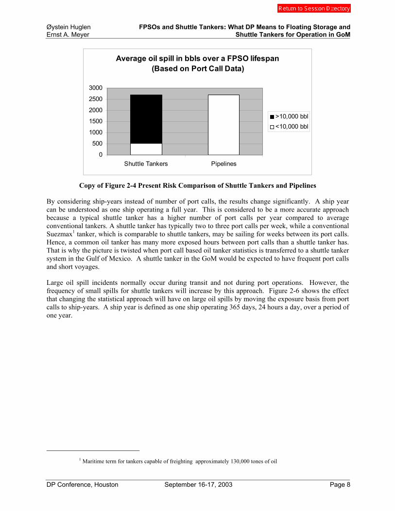
Copy of Figure 2-4 Present Risk Comparison of Shuttle Tankers and Pipelines
By considering ship-years instead of number of port calls, the results change significantly. A ship year can be understood as one ship operating a full year. This is considered to be a more accurate approach because a typical shuttle tanker has a higher number of port calls per year compared to average conventional tankers. A shuttle tanker has typically two to three port calls per week, while a conventional Suezmax1 tanker, which is comparable to shuttle tankers, may be sailing for weeks between its port calls. Hence, a common oil tanker has many more exposed hours between port calls than a shuttle tanker has. That is why the picture is twisted when port call based oil tanker statistics is transferred to a shuttle tanker system in the Gulf of Mexico. A shuttle tanker in the GoM would be expected to have frequent port calls and short voyages.
Large oil spill incidents normally occur during transit and not during port operations. However, the frequency of small spills for shuttle tankers will increase by this approach. Figure 2-6 shows the effect that changing the statistical approach will have on large oil spills by moving the exposure basis from port calls to ship-years. A ship year is defined as one ship operating 365 days, 24 hours a day, over a period of one year.
1 Maritime term for tankers capable of freighting approximately 130,000 tones of oil
Øystein Huglen FPSOs and Shuttle Tankers: What DP Means to Floating Storage and Ernst A. Meyer Shuttle Tankers for Operation in GoM
DP Conference, Houston September 16-17, 2003 Page 9
Average oil spill in bbls over a FPSO lifespanUsing ship year instead of port calls
0
500
1000
1500
2000
2500
3000
Shuttle Tankers Pipelines
>10,000 bbl<10,000 bbl
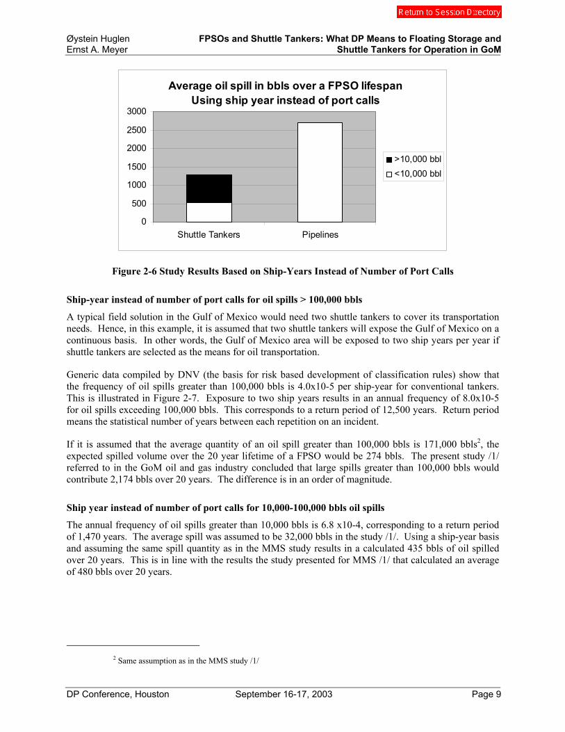
Figure 2-6 Study Results Based on Ship-Years Instead of Number of Port Calls
Ship-year instead of number of port calls for oil spills > 100,000 bbls
A typical field solution in the Gulf of Mexico would need two shuttle tankers to cover its transportation needs. Hence, in this example, it is assumed that two shuttle tankers will expose the Gulf of Mexico on a continuous basis. In other words, the Gulf of Mexico area will be exposed to two ship years per year if shuttle tankers are selected as the means for oil transportation.
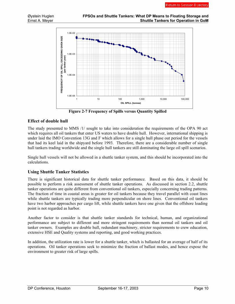
Generic data compiled by DNV (the basis for risk based development of classification rules) show that the frequency of oil spills greater than 100,000 bbls is 4.0x10⁻⁵ per ship-year for conventional tankers. This is illustrated in Figure 2-7. Exposure to two ship years results in an annual frequency of 8.0x10⁻⁵ for oil spills exceeding 100,000 bbls. This corresponds to a return period of 12,500 years. Return period means the statistical number of years between each repetition on an incident.
If it is assumed that the average quantity of an oil spill greater than 100,000 bbls is 171,000 bbls2, the expected spilled volume over the 20 year lifetime of a FPSO would be 274 bbls. The present study /1/ referred to in the GoM oil and gas industry concluded that large spills greater than 100,000 bbls would contribute 2,174 bbls over 20 years. The difference is in an order of magnitude.
Ship year instead of number of port calls for 10,000-100,000 bbls oil spills
The annual frequency of oil spills greater than 10,000 bbls is 6.8 x10⁻⁴, corresponding to a return period of 1,470 years. The average spill was assumed to be 32,000 bbls in the study /1/. Using a ship-year basis and assuming the same spill quantity as in the MMS study results in a calculated 435 bbls of oil spilled over 20 years. This is in line with the results the study presented for MMS /1/ that calculated an average of 480 bbls over 20 years.
2 Same assumption as in the MMS study /1/
Øystein Huglen FPSOs and Shuttle Tankers: What DP Means to Floating Storage and Ernst A. Meyer Shuttle Tankers for Operation in GoM
DP Conference, Houston September 16-17, 2003 Page 10
1.0E-05
1.0E-04
1.0E-03
1.0E-02
1 10 100 1,000 10,000 100,000
OIL SPILL (tonnes)
FREQ
UEN
CIY
OF
OIL
SPI
LL E
XCEE
DIN
G G
IVEN
SIZ
E (p
er ta
nker
yea
r)
Figure 2-7 Frequency of Spills versus Quantity Spilled
Effect of double hull The study presented to MMS /1/ sought to take into consideration the requirements of the OPA 90 act which requires all oil tankers that enter US waters to have double hull. However, international shipping is under laid the IMO Convention 13G and F which allows for a single hull phase out period for the vessels that had its keel laid in the shipyard before 1993. Therefore, there are a considerable number of single hull tankers trading worldwide and the single hull tankers are still dominating the large oil spill scenarios.
Single hull vessels will not be allowed in a shuttle tanker system, and this should be incorporated into the calculations.
Using Shuttle Tanker Statistics There is significant historical data for shuttle tanker performance. Based on this data, it should be possible to perform a risk assessment of shuttle tanker operations. As discussed in section 2.2, shuttle tanker operations are quite different from conventional oil tankers, especially concerning trading patterns. The fraction of time in coastal areas is greater for oil tankers because they travel parallel with coast lines while shuttle tankers are typically trading more perpendicular on shore lines. Conventional oil tankers have two harbor approaches per cargo lift, while shuttle tankers have one given that the offshore loading point is not regarded as harbor.
Another factor to consider is that shuttle tanker standards for technical, human, and organizational performance are subject to different and more stringent requirements than normal oil tankers and oil tanker owners. Examples are double hull, redundant machinery, stricter requirements to crew education, extensive HSE and Quality systems and reporting, and good working practices.
In addition, the utilization rate is lower for a shuttle tanker, which is ballasted for an average of half of its operations. Oil tanker operations seek to minimize the fraction of ballast modes, and hence expose the environment to greater risk of large spills.

Øystein Huglen FPSOs and Shuttle Tankers: What DP Means to Floating Storage and Ernst A. Meyer Shuttle Tankers for Operation in GoM
DP Conference, Houston September 16-17, 2003 Page 11
2.5 Study Proposal
Flexibility in choosing storage and transportation philosophies will stimulate enhancement of business performance in the future Gulf of Mexico based oil and gas industry. It is however important that this flexibility is established on the right basis.
This paper shows that the lack of flexibility with respect to choice of transport system associated with an oil field development is based on a portion of the risk picture only, and that this portion is based on a discussable approach.
A complete study would provide the necessary knowledge covering all facets of functions combined with the different lifecycle stages of a transport system, whether it is shuttle tankers or pipelines in the Gulf of Mexico. This knowledge will also enable the industry to make sound decisions based on smaller and quicker analyses that are tailor made for the field development in question. As explained in section 2.3, small adjustments to the study basis may turn the risk picture completely.

Øystein Huglen FPSOs and Shuttle Tankers: What DP Means to Floating Storage and Ernst A. Meyer Shuttle Tankers for Operation in GoM
DP Conference, Houston September 16-17, 2003 Page 12
3. Shuttle Tanker Experience from the North Sea
3.1 State-of-the-Art Concepts
After having been successfully used onboard diving vessels and other offshore related vessels for several years, DP operation of shuttle tankers was a major step forward when first tested at Statfjord field in 1982. Prior to that, all shuttle tanker loadings had been performed by manual operations. Following the successful trials Statoil, as the first oil company in the world, decided to base all their offshore loading on DP operated shuttle tankers.
First generation DP shuttle tankers were conventional single hull tankers modified for offshore loading. Today nearly all shuttle tankers are purpose built tankers. Typically it will be an IMO DP Class 2 double hull tanker equipped with twin propulsion engines of up to 15000 HP each; two high efficiency rudders; two bow thrusters of 2400 HP each, out of which one is either retractable tunnel thruster or of retractable azimuth type; two tunnel thrusters aft of 1400 HP each, or alternatively one retractable azimuth thruster of similar size.
Along with the evolution of the tankers, new loading systems were developed, demanding more and more with respect to position keeping capability of the shuttle tankers. As an environmental ‘reference’ standard for DP operations 4.5 meters significant wave height was set as hook-up criteria for the tanker; 5.5 meter significant wave height as position keeping ability.
Over the years new and improved DP positioning reference systems (PRS) have been developed. IMO DP Class 2 has a requirement of a minimum of 3 independent PRS systems to be installed and to perform DP Class 2 operation. The most widespread system in the North Sea today is DGPS. A special version named DARPS which is providing both absolute and relative positioning, has become a North Sea standard. Also the Artemis, a microwave based tracking system, has been circulated around all of the North Sea. Hydro acoustics is normally used as a third system. Improved versions like the HIPAP gives accuracy in the centimeter range when utilized at moderate water depths. Laser based PRS systems are less used as they have reduced performance in environments with rain, hail and snow.
Also tailor made DP software has been developed over the time. Basically all DP operation of shuttle tankers is based on the ‘weather vane’ principle; i.e. the shuttle tanker will try to maintain a position where the environmental forces stemming from wind, waves and current, are kept at a minimum.
Figure 3.1
Øystein Huglen FPSOs and Shuttle Tankers: What DP Means to Floating Storage and Ernst A. Meyer Shuttle Tankers for Operation in GoM
DP Conference, Houston September 16-17, 2003 Page 13
The most challenging DP operation of a shuttle tanker is the tandem loading. This is due to the fact that the FSO / FPSO normally represents significant surge and fish tailing movements which the shuttle tanker has to relate to. The difficult FSO movements are to a large extent eliminated by providing thrusters for heading and position control of the FSO. To overcome the problem a special ‘Tandem Loading’ software has also been developed. This will allow the FSO / FPSO to move around freely within given limits, without the shuttle tanker moored behind attempting to follow its movement. Another benefit from this solution is a significant reduction in fuel consumption.
3.2 Contrast of Close Proximity with DP versus Moored Vessels
Operation of large vessels on DP close to other structures is today common practice in the North Sea. As the DP models were developed, the computer was able to handle the vessel even better than the most skilled captains. In brief, the main advantages of using a DP system can be summarized as follows:
• The availability of the export system has increased due to avoidance of snap loads in the hawser. In addition, this increases the lifetime of the hawser.
• The system is able to keep the vessel in a more stable position than by manual operation. • Maneuvering systems onboard, i.e. propellers and machinery are operated more smoothly, reducing
wear and tear and the risk of break-down. • The life time of the hawser has been greatly improved. • The pressure on the captain is reduced as the function is changed from active operation to control of a
system. • The human factor of tiredness and associated likelihood of mal operation is significantly reduced.
The development of DP operated shuttle tankers represents a significant contribution to the successful history of offshore loading in the North Sea. However, there are still certain concerns in connection with the DP operations, although it seems that major shortcomings have been sorted out. Some of the major concerns can be listed as:
• Inherent system failures (“bugs”) in the system might still be present, resulting in uncontrolled drive- or drift off incidents.
• The automation may lead to a too high confidence in the system, and thereby reduce the alertness of the operator.
• Captains are losing the experience of “hands on” operation, which is essential and useful in the event of an emergency situation.
DP operation of a large storage vessel in a distance of 500 meters from a production unit might appear risky. However, the vessels should be IMO DP class 2, with a high degree of maneuverability and strict requirements regarding redundancy of essential systems. North Sea experience through several years of operation of DP shuttle tankers, gives the confidence that such a system work efficient and safely.
3.3 Oil Spill Statistics from Navion Operations
Since 1977, Navion has performed more than 13,000 offshore loading operations in which approximately 10 billion barrels of oil have been shipped safely to onshore terminals. The Navion fleet has not caused any major oil spills, and only 7 oil spills above 1 barrel have occurred. On average, each shuttle tanker carries out about 50 liftings a year. The frequency of oil spills above 1 barrel derived from these numbers can be presented as:
Øystein Huglen FPSOs and Shuttle Tankers: What DP Means to Floating Storage and Ernst A. Meyer Shuttle Tankers for Operation in GoM
DP Conference, Houston September 16-17, 2003 Page 14
• 0.027 spills per ship year (1 spill per 37 ship years). • 0.0005 spills per loading operation (1 spill per 1,860 loading operations). • 0.0007 spills per 1 million barrels of oil shipped.
4. Differences and Similarities between the North Sea and the Gulf of Mexico
4.1 Environmental Conditions in the Gulf of Mexico Compared to the North Sea
The environmental conditions in the Gulf of Mexico are nearly the same as the environmental conditions in the North Sea.
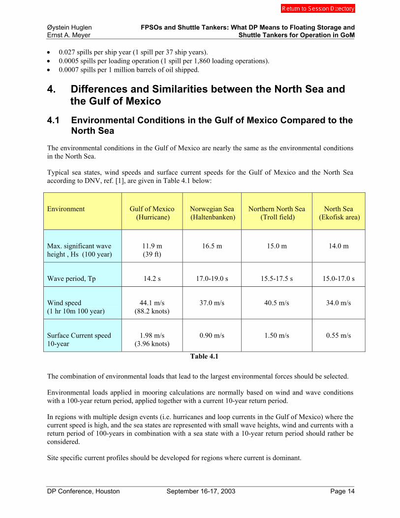
Typical sea states, wind speeds and surface current speeds for the Gulf of Mexico and the North Sea according to DNV, ref. [1], are given in Table 4.1 below:
Environment Gulf of Mexico (Hurricane)
Norwegian Sea (Haltenbanken)
Northern North Sea (Troll field)
North Sea (Ekofisk area)
Max. significant wave height , Hs (100 year)
11.9 m (39 ft)
16.5 m 15.0 m 14.0 m
Wave period, Tp 14.2 s 17.0-19.0 s 15.5-17.5 s 15.0-17.0 s
Wind speed (1 hr 10m 100 year)
44.1 m/s (88.2 knots)
37.0 m/s 40.5 m/s 34.0 m/s
Surface Current speed 10-year
1.98 m/s (3.96 knots)
0.90 m/s 1.50 m/s 0.55 m/s
Table 4.1
The combination of environmental loads that lead to the largest environmental forces should be selected.
Environmental loads applied in mooring calculations are normally based on wind and wave conditions with a 100-year return period, applied together with a current 10-year return period.
In regions with multiple design events (i.e. hurricanes and loop currents in the Gulf of Mexico) where the current speed is high, and the sea states are represented with small wave heights, wind and currents with a return period of 100-years in combination with a sea state with a 10-year return period should rather be considered.
Site specific current profiles should be developed for regions where current is dominant.

Øystein Huglen FPSOs and Shuttle Tankers: What DP Means to Floating Storage and Ernst A. Meyer Shuttle Tankers for Operation in GoM
DP Conference, Houston September 16-17, 2003 Page 15
The relative direction of wind, waves and current should also be considered in the design.
4.2 Energetic Currents and Loop Currents
Energetic current events occur in the deep water region of the Gulf of Mexico. The classes of currents are:
• Currents resulting from energetic, episodic atmospheric events (e.g. tropical cyclones such as hurricanes, extratropical cyclones, and cold air outbreaks);
• Surface-intensified currents arising from major circulation features (i.e. the Loop Current, the anticyclonic eddies derived there from , both cyclonic and anticyclonic eddies spun up in the Gulf, and other low-frequency circulation features driven by local wind stress distributions);
• Currents extending from about 800 m through the deeper water column, sometimes with bottom intensification; and
• High-speed, subsurface-intensified currents.
The phenomena of most concern in the past to deep water operators in the Gulf of Mexico are surface-intensified currents associated with the Loop Current (LC), Loop Current eddies (LCEs), and other eddies (both anticyclonic and cyclonic). The currents associated with LC and LCEs extend down into the water column to at least 800 m. T.
The Gulf’s circulation is dominated by the Loop Current, an energetic current of warm subtropical water that enters the Gulf through the Yucatan Strait, extends northward, then loops around to the south and ultimately exits the Gulf through the Florida Strait. The position and strength of this Loop Current (LC) exhibits considerable variability they may have surface speeds of 1.5 to 2.0 m/s or more.
After their separation from the Loop Current, LCEs move into the western Gulf and in the process may interact with other eddies or with the continental margins to form additional eddies. The net result is that at almost any given time, the Gulf is populated with numerous eddies, interacting with one another and with margins.
Offshore operators must design their drilling and production system to account for forces exerted by energetic currents.
Øystein Huglen FPSOs and Shuttle Tankers: What DP Means to Floating Storage and Ernst A. Meyer Shuttle Tankers for Operation in GoM
DP Conference, Houston September 16-17, 2003 Page 16
4.3 Transfer of Experience for Operation in GoM
The experience gained in operation of FPSO vessels, FSO vessels and shuttle tankers in the North Sea can be transferred to Gulf of Mexico.
A DP operated storage tanker should be a powerful unit, be able to maintain heading control and operate under maximum LOOP current condition.
A shuttle tanker concept as state of the art in the North Sea is regarded a suitable solution for the Gulf of Mexico. This category of shuttle tanker will ensure a reliable, safe and efficient transportation. The vessel system gives the operator a high degree of flexibility as the crude can be delivered to the refinery offering the best price. Depending on what size of shuttle tankers is being used, also refineries on the West coast can be reached.
It is essential for the safety that the crews are being well trained, and a program for simulation training should be considered.
Taking the above-mentioned precautions an efficiency of more than 99 % should be expected.
4.4 Advantages and Operational Benefits for DP Operated Vessel System in Deepwater / GoM
The advantages and operational benefits for DP system in GoM may be as follows:
• No need for connections of pipelines • Storage capacity can be on the storage vessel • DP operated storage vessel • No mooring cost • Easy and quick hook-up, connection and/or disconnection • Safe distance from production platform • Added fuel cost for DP which can be overcome by using produced associated gas • Weight and cost saving as equipment can be replaced or located on the vessels • Offloading from FSO by DP operated shuttle tanker • The system can operate and be connected in maximum loop currents. • Early start up of transportation

Øystein Huglen FPSOs and Shuttle Tankers: What DP Means to Floating Storage and Ernst A. Meyer Shuttle Tankers for Operation in GoM
DP Conference, Houston September 16-17, 2003 Page 17
5. Offloading SPARs to Shuttle Tankers in the GoM - The S-S-STM concept
To meet the transportation demand from an increasing number of SPAR, TLP and semi-submersible production installations in the GoM that do not have storage, American Shuttle Tankers (AST) and Navion jointly developed an oil export system to work with any kind of called Separate Storage Shuttling (S-S-STM). The concept is based on a Dynamically Positioned (DP) storage tanker with an offloading system to DP shuttle tankers. DP positioning of large crude vessels and offloading from FPSOs or FSOs to shuttle tankers is known and well-qualified technology. The S-S-STM concept is however unique due to the DP operated floating storage. A tanker with diesel electric propulsion will be ideal for the task and such a vessel (“Navion Norvegia”) is used as a basis, ref. Fig. 5.1. However, other tankers could also be used, provided the machinery is laid out for extensive running on low propulsion load.
The Separate Storage ShuttlingTM (S-S-STM) system was developed during 2002 and is the subject of multiple patent applications.
Figure 5.1
5.1 Positioning strategy of S-S-STM
When developing the positioning strategy, safety has been the key issue. The weather conditions in GoM, and especially the loop current is demanding for DP operated vessels. In order to keep the position, it is essential that the vessel always can have a position where the environmental forces can be met head on. Additionally, a key issue for the concept has been that the vessel always should be located leeward of the production unit and in such a way that the vessel never is heading directly towards the production unit, except during short transition periods. These short periods will be when the vessel is at the extreme edge of the operational sector, and the direction of the environmental forces is changing in such a way that a relocation of the vessel is necessary in order to fulfill the above-mentioned safety requirement
Except for the few situations when relocating the storage vessel may be necessary, the FSO will not head towards the production unit. Hence the risk for drive off failure of the DP system causing collision between the storage vessel and the production unit will be negligible. To further increase the safety of the concept, the storage vessel should be an IMO DP2 class vessel, with redundant control and positioning systems.
Øystein Huglen FPSOs and Shuttle Tankers: What DP Means to Floating Storage and Ernst A. Meyer Shuttle Tankers for Operation in GoM
DP Conference, Houston September 16-17, 2003 Page 18
As a starting point, AST has regarded 500 m. as adequate distance between the two units; however, final distance will be established based on a risk assessment study.
5.2 Propulsion layout and machinery systems
The diesel electric driven shuttle tanker M/T “Navion Norwegia” has been the basis for the concept. Presently the vessel is an IMO DP class 1 vessel, with the following machinery layout:
• Four (4) Diesel engines, with a total output of 26,320 kW • 0ne (1) main propeller, driven by two (2) electric motors on the same shaft. Total output of 16,340
kW • Three (3) bow tunnel thrusters, each with a capacity of 1,750 kW • Two (2) stern tunnel thrusters, each with a capacity of 1,750 kW
Relatively small modifications to the machinery systems will be necessary in order to convert the vessel to an IMO DP class 2 vessel and to adapt it for the dedicated task as a DP operated floating storage unit. The following modifications are identified:
• A review of the switch board configuration • Installation of two (2) additional azimuth thrusters of approx. 2.200 kW each, one (1) located where
the present aft bow tunnel thrusters is, and one (1) located aft, in the pump room area.
Upon request from Navion, Kongsberg Simrad, the supplier of the DP system, has carried out a study demonstrating that the proposed vessel can maintain the position in a maximum loop current of 4,1 knots. Further study demonstrated that the vessel can keep position through a 10 year winter storm condition, even with a main propeller failure.
5.3 Oil transfer system between Production Platform) and DP Storage Vessel
The basis for the concept has been that the oil transfer system shall interfere as little as possible with the system on the Platform and to keep the Platform based weights to a minimum. This means that the equipment necessary on the Platform is limited to:
• An A-frame and necessary winches for retrieval of the hose • Hose connection unit of quick connection/disconnection type • Necessary instrumentation
The equipment can, for example, be located in one of the corners of the Platform’s deck structure, allowing the Storage Vessel to operate in a sector of approx 210 deg. However, final operating sector has to be established by a more thorough study.
The main and heavy parts of the system will be located on the Storage Vessel. This will consist of:
• Storage drum • Hang off system • Swivel

Øystein Huglen FPSOs and Shuttle Tankers: What DP Means to Floating Storage and Ernst A. Meyer Shuttle Tankers for Operation in GoM
DP Conference, Houston September 16-17, 2003 Page 19
The oil will be transferred from the platform to the storage vessel via a flexible hose. Based on an assumed production of 100.000 barrels /day, the hose diameter should be about 8 inches. The hose is suspended in a catenary shape between the two units. See fig. 5.3. On the Storage Vessel side, the hose will enter the vessel through a moon pool, located approximately mid-ship. In connection with the moon pool, the hose will be disconnected from the storage drum and hooked on a hang off device. See fig. 5.4. Immediately under the hang-off device, there will be located a swivel, and this will allow the DPSV to freely weather vane 360 degrees in both directions.
Figure 5.3 Figure 5.4
The DPSV will operate on a predefined sector of a circle, with a radius of approximately 500 m corresponding to the distance from the PU. The DP system thus has to be programmed in such a way that the vessel can freely weather vane around the center of the moon pool as it is moving along the circle. Necessary alarm limits have to be established.
In case of a disconnection, the hose will be disconnected at the platform, and the end termination unit will be lowered to the surface. In connection with the termination unit, there will be an inflatable buoy that will be released as the end piece enters into the water, and thereby keep the hose in the catenary shape. The hose is then winched onto the storage drum located at the deck of the Storage Vessel.
When deploying the system, the Storage Vessel goes up to the leeward side of the Platform, from where a messenger line is transferred to the Storage Vessel. After the messenger line has been connected to the hose termination unit, the Storage Vessel is slowly being relocated to the predefined operating circle, as is pays out the hose. When the Storage Vessel is in correct position, the hose is reconnected at both units, and the transfer of oil can start.
Upon request from Navion, APL carried out a study demonstrating that the maximum loop current will have minor effect on the suspended transfer hose. The hose is proposed to be of a continuous non-bonded type. Such hoses will have a lifetime of more than 20 years. However, less expensive hoses of marine type could also be used in case of fields with shorter lifetime.
A telemetry based safety system will be included, enabling the Storage Vessel to stop the transfer pumps on the PU in the event of a critical situation. This will be a fail-safe system. In case of emergency, the

Øystein Huglen FPSOs and Shuttle Tankers: What DP Means to Floating Storage and Ernst A. Meyer Shuttle Tankers for Operation in GoM
DP Conference, Houston September 16-17, 2003 Page 20
transfer hose can be disconnected instantaneously from the Platform. The system can be redeployed within less than six (6) hours.
The Storage Vessel may be classed as an offshore installation, and by that, the class requirement of docking every 5th year may be omitted and substituted by an ongoing in-situ inspection program similar in principle to that used on FPSOs. In the event that the Storage Vessel for any reason has to be removed from the location, loading could take place directly to the Shuttle Tanker. This will, however, require that a special hose is available, and that reduced operating thresholds are established.
5.4 Oil Transfer System between DP Storage Vessel and Shuttle Tanker
The concept is based on using DP operated Shuttle Tankers. In principle, the operation will be similar to the offshore loading operations taking place in the North Sea (see fig. 3.1). However, in order to limit the interference between two DP operated vessels the concept is based on not using any mooring line(s) between the storage vessel and the shuttle tanker. This solution represents new technology, however, based on more than 15 years of DP offshore loading operations. Navion is confident that the operation can be performed in a safe and efficient way.
A stern discharge system will be installed on the storage vessel, and the shuttle tanker will approach from stern. After having obtained a stable position, the loading hose will be transferred from the storage vessel. The diameter of this hose will typically be 16 inches. In order to reduce the VOC emissions, a hose of a smaller diameter is included. Through this hose, the tank atmosphere in the shuttle tanker cargo tanks is displaced to the storage vessel as the crude oil is transferred.
The discharge rate will be in the range of 30-40,000 barrels/hour.
A safety system based on the telemetry will be included. The system will, in principal, be the same as is used in the North Sea, i.e. a fail-safe system.
5.5 Operational Strategy Analysis
DP-simulations for the S-S-STM concept have been performed by Kongsberg Simrad on behalf of Navion, based upon typical Gulf of Mexico environmental conditions.
5.5.1 DP Operational Modes and Functions
Weathervane mode The vessel is allowed to rotate with the wind, current and waves around a fixed or moving point called the terminal point. Neither the heading nor the position of the vessel is fixed. The heading of the vessel is controlled to point towards the terminal point. The position of the vessel is controlled to follow a circle, called the setpoint circle, around the terminal point.
Auto Position mode The DP system automatically maintains the heading and position of the vessel, meaning that all axis of motion are controlled. When using this mode, the requirement on thrusters capacity is much higher than that for weathervane mode.

Øystein Huglen FPSOs and Shuttle Tankers: What DP Means to Floating Storage and Ernst A. Meyer Shuttle Tankers for Operation in GoM
DP Conference, Houston September 16-17, 2003 Page 21
Storage Vessel AUTO mode The most realistic operational mode of the FSO during the offloading operation is full DP Auto mode. This means that the Storage Vessel will keep both position and heading, and there will be a minimum of movement for the shuttle tanker operation behind the Storage Vessel. Any heading changes must be agreed upon between the DP operators on the Storage Vessel and the shuttle tanker. This is the same as is applied in the North Sea.
5.5.2 Hurricane Strategy The environmental conditions evaluated are representative for the Gulf of Mexico, but excluding hurricane conditions or other weather conditions causing production shutdown.
It is assumed that the production will be closed down during a hurricane, and that the loading hose between the storage vessel and the platform will be disconnected.
In case of a disconnection, the hose will be disconnected at the platform, and the end termination unit lowered to the surface. In connection with the termination unit, there will be an inflatable buoy that will be released as the end piece enters into the water, and thereby, keep the hose in the catenary shape. The hose is then winched onto the storage drum located at the deck of the Storage Vessel.
5.5.3 Design Criteria - Storage Vessel The structural strength of the storage vessel will be verified according to GoM 100-year storm and hurricane conditions, as the vessel will stay offshore, but disconnected from the production unit in such weather conditions.
A fatigue assessment for relevant GoM service conditions will also be performed.
As long as the original vessel design is based on basic Classification of Ship rules (20-year environmental conditions in the North Atlantic), these assessments should not cause any problems or any additional upgrades for existing vessels.

Øystein Huglen FPSOs and Shuttle Tankers: What DP Means to Floating Storage and Ernst A. Meyer Shuttle Tankers for Operation in GoM
DP Conference, Houston September 16-17, 2003 Page 22
5.5.4 Environmental Conditions - Storage Vessel DP and Hose Configuration
Environmental conditions used for the continuous FSO DP loading and hose configuration assessment are:
Environment 10-year Loop Current Maximum Loop Current 10-year Winter storm
Wave Hs (m) Tp (s)
5.1 9.9
2.0 6.0
5.9 10.5
Wind (m/s) (1 hr at 10 m)
15.0 8.0 20.0
Current (m/s) 1.7 (3.3 knots)
2.1 (4.1 knots)
0.6 (1.2 knots)
Table 5.1.
5.5.5 Operational Conditions - Tandem Loading The maximum environmental condition for the tandem loading operation is as follows:
• Waves Hs max. = 5 m, Tp = 10 s • Wind V max. = 15.0 m/s (1 hr at 10 m) • Current V max. = 2.4 knots ( 1.2 m/s)
The above stated maximum current can be increased if the regularity for tandem loading appears to be too low (adjustment of Storage Vessel DP capability and relative angle). Feedback is required on this item before any new optimization takes place.
5.5.6 DP Capability DP capability plots are used during the design phase to determine thrusters size required to counteract environmental forces.
The shuttle tanker, Navion Norvegia, (with two azimuth thrusters added) has been analyzed for the Storage Vessel operation. A converted 40.000dwt product tanker has been analyzed for the shuttle tanker operation.
When analyzing the capability plots for DP capability, the mode of operation should be considered:

Øystein Huglen FPSOs and Shuttle Tankers: What DP Means to Floating Storage and Ernst A. Meyer Shuttle Tankers for Operation in GoM
DP Conference, Houston September 16-17, 2003 Page 23
• Weathervane mode; the requirements should be met within a sector of approx. + 15 degrees relative to the bow. This narrow sector is sufficient, as the vessel automatically will adapt to the optimum heading.
• Auto position mode where the vessel to a large degree adapt the heading to the environmental conditions (i.e. Storage Vessel operation during offloading); the requirement should be met within a sector of approx. + 20 degrees relative to the bow.
Capability plots are made for three different environmental conditions. Two additional plots are made for the 10 year Winter Storm condition with two different single failure situations (loss of main propeller, and loss of bow azimuth thrusters and one stern thruster).
The main results from the capability plots show that the Maximum Loop Current situation is the most limited in terms of capacity. The Capability plot for this situation is shown in figure 5.5.
Figure 5.5
For the offloading environmental conditions, simulations have been performed in order to establish the maximum sea current where the requirement is met for 1-year winter storm condition for predicted wind and waves.
The Kongsberg Simrad study demonstrates that the proposed vessel can maintain the position in max loop current (4.1 knot according to Deep Star). Further, the study demonstrates that the vessel can keep the position through a 10 year winter storm condition with even a main propeller failure.
S-S-STM CONCEPTENV. CONDITIONS MAXIMUM LOOP CURRENT
FSO

Øystein Huglen FPSOs and Shuttle Tankers: What DP Means to Floating Storage and Ernst A. Meyer Shuttle Tankers for Operation in GoM
DP Conference, Houston September 16-17, 2003 Page 24
5.5.7 Hose Assessment Study APL has performed a study related to the criticality of the flexible hose configuration in static and dynamic conditions based on the same environmental criteria as used for the DP simulations. The APL study indicates no critical elements in the hose configuration.
5.6 Why capability of S-S-STM is Important for Deepwater in GoM
Although FPSOs are now approved for use in the Gulf of Mexico there are none planned currently and many other kinds of platforms are both in use and planned for the deep water of the GoM In this context, the S-S-STM concept has been developed to serve any kind of platform. The DP Storage vessel will be a powerful unit, able to operate under maximum LOOP current condition of 4.1 knots. The concept will ensure a reliable, safe and efficient transportation to a competitive price. The system gives the operator a high degree of flexibility as the crude can be delivered to the refinery offering the best price. Depending on what size of shuttle tankers are being used, refineries on the West coast of the U.S. can be reached. It is essential that the crews are well trained, and a program for simulation training should be considered. Taking the above-mentioned precautions an efficiency of more than 99 % should be expected.
The shuttle tankers involved in the transportation will fall under Jones Act requirements. In order to be able to offer a system that can be in operation within one year, AST has entered into agreement with a U.S. ship-owner who today has the ownership of Jones Act vessels suitable for conversion into shuttle tankers. Such vessels will be used as an interim solution until American shipyards can deliver newly built shuttle tankers.
Navion has carefully studied the concept, and identified and cost estimated the necessary modifications of both the proposed Storage Vessel as well as the shuttle tankers. Vendors have been contacted, and no major obstacles can be identified. The concept can be in operation in approximately 12 months after a contract award. This is including necessary docking time and production of key equipment. The most critical components are identified as the thrusters and main propeller.
The concept has been presented for the US Coast Guard and the MMS as well as classification societies. No “show stoppers” were found subject to proper risk analyses that could demonstrate the soundness of the system.

Øystein Huglen FPSOs and Shuttle Tankers: What DP Means to Floating Storage and Ernst A. Meyer Shuttle Tankers for Operation in GoM
DP Conference, Houston September 16-17, 2003 Page 25
6. Conclusions This paper shows that the experience from the North Sea with DP operations of large crude vessels is transferable to GoM conditions.
Especially for deepwater areas where infrastructure on the sea bed is challenging, a DP based shuttle tanker system is expected to be viable and cost effective.
The risk associated with shuttle tankers in the Gulf of Mexico is known to a limited extent and may as it is presented today. Hence, the GoM based oil industries could miss opportunities for safe and responsible business enhancements by not considering alternative transportation methods on the right basis.
In order to establish a sound basis for consideration of shuttle tankers, an objective and independent risk assessment should be executed. The risk assessment should be:
• carried out for shuttle tanker operations in the Gulf of Mexico, • based on shuttle tanker statistics in combination with oil tanker statistics calibrated for the
characteristics that are special for shuttle tankers, and • cover commercial, environmental, and safety risks over a shuttle tanker life cycle.
The S-S-STM will be able to provide the oil industry with a reliable transport system for deepwater production units within 12 months after a contract award.
7. Acknowledgements The authors would like to thank Statoil and Global Maritime who have contributed help and data in preparing this paper.
Øystein Huglen FPSOs and Shuttle Tankers: What DP Means to Floating Storage and Ernst A. Meyer Shuttle Tankers for Operation in GoM
DP Conference, Houston September 16-17, 2003 Page 26
8. References [1] Comparative Risk Analysis for Deepwater Production Systems Prepared for MMS,
January 2001 [2] Proposed use of Floating Production Storage and Offloading Systems on the Gulf Of
Mexico Outer continental Shelf - Environmental Impact Study [3] DNV Offshore Standard DNV-OS-E301, Position Mooring, June 2001. Public Domain Reports
• ACDS (1991), “Major Hazard Aspects of the Transport of Dangerous Substances”, Advisory Committee on Dangerous Substances, Health & Safety Commission, HMSO.
• NPC (1976), “Analysis of Marine Incidents in Ports and Harbours”, National Ports Council, London. • Robinson, R.G.J. & Lelland, A.N. (1995), “Marine Incidents in Ports and Harbours in Great Britain,
1988-1992”, Report AEA/CS/HSE-R1051, AEA Technology.
DNV Projects
• Technica Project C1216, “Port Risks in Great Britain from Marine Transportation of Dangerous Substances in Bulk: A Risk Assessment”, Report for Health & Safety Executive, October 1990.
• DNV Technica Project C6124, “Quantitative Risk Assessment of the Transport of LPG and Naphtha in Hong Kong, Methodology Report”, April 1996.
• DNV Technica Project C6185, “Safety Assessment of Passenger/Ro-Ro Vessels, Methodology Report”, October 1996.
• DNV Project C383184, “Demonstration Formal Safety Assessment of Ship Rules” (Report 99-2047). • DNV Technical Report 97-2039, “SAFECO, WP III.2, Statistical Analysis of Ship Accidents”. • DNV Technical Report 99-2011, “SAFECO II, WP III.3, D22c, Consequence Model for Ship
Accidents”. • DNV Technical Report 99-2028, “Historical Risk Levels in the Maritime Industry”, in draft.
Øystein Huglen FPSOs and Shuttle Tankers: What DP Means to Floating Storage and Ernst A. Meyer Shuttle Tankers for Operation in GoM
DP Conference, Houston September 16-17, 2003 Page 27
About Navion
Navion is a shipping company located in Stavanger Norway. The company was formerly a subsidiary company of Statoil but is now owned by Teekay Shipping Corporation.
The company ranks as the world leader in offshore loading, and occupies a dominant position in crude oil and product transportation in the Atlantic basin. Long experience from these waters has contributed to the development of pioneering technologies.
About DNV Consulting
Established in 1864, Det Norske Veritas (DNV) is an independent foundation with the objective of safeguarding life, property and the environment and is a leading provider of services for managing risk.
DNV Consulting provides management and technology consulting worldwide. Our aim is to provide a full range of services to clients in the area of risk management. We are mastering technology and business risk - and their interactions. DNV Consulting is located in Norway, UK, Germany and U.S.A, while DNV has offices in more than 100 countries.