east african standard - eac quality€¦ · · 2010-07-17draft for comments only — not to be...
TRANSCRIPT
Draf
t for
com
men
ts on
ly —
Not
to b
e cit
ed a
s Eas
t Afri
can
Stan
dard
CD/K/015-1:2009ICS 23.060.01; 91.140.60
© EAC 2010 First Edition 2010
EAST AFRICAN STANDARD Valves for water supply — Fitness for purpose requirements and appropriate verification tests — Part 1: General requirements
EAST AFRICAN COMMUNITY
Draf
t for
com
men
ts on
ly —
Not
to b
e cit
ed a
s Eas
t Afri
can
Stan
dard
CD/K/015-1:2009
ii © EAC 2010 — All rights reserved
Foreword Development of the East African Standards has been necessitated by the need for harmonizing requirements governing quality of products and services in East Africa. It is envisaged that through harmonized standardization, trade barriers which are encountered when goods and services are exchanged within the Community will be removed. In order to meet the above objectives, the EAC Partner States have enacted an East African Standardization, Quality Assurance, Metrology and Test Act, 2006 (EAC SQMT Act, 2006) to make provisions for ensuring standardization, quality assurance, metrology and testing of products produced or originating in a third country and traded in the Community in order to facilitate industrial development and trade as well as helping to protect the health and safety of society and the environment in the Community. East African Standards are formulated in accordance with the procedures established by the East African Standards Committee. The East African Standards Committee is established under the provisions of Article 4 of the EAC SQMT Act, 2006. The Committee is composed of representatives of the National Standards Bodies in Partner States, together with the representatives from the private sectors and consumer organizations. Draft East African Standards are circulated to stakeholders through the National Standards Bodies in the Partner States. The comments received are discussed and incorporated before finalization of standards, in accordance with the procedures of the Community. Article 15(1) of the EAC SQMT Act, 2006 provides that “Within six months of the declaration of an East African Standard, the Partner States shall adopt, without deviation from the approved text of the standard, the East African Standard as a national standard and withdraw any existing national standard with similar scope and purpose”.
East African Standards are subject to review, to keep pace with technological advances. Users of the East African Standards are therefore expected to ensure that they always have the latest versions of the standards they are implementing.
© East African Community 2010 — All rights reserved*
East African Community
P O Box 1096
Arusha
Tanzania
Tel: 255 27 2504253/8
Fax: 255-27-2504481/2504255
E-Mail: [email protected]
Web: www.each.int
*
© 2010 EAC — All rights of exploitation in any form and by any means reserved worldwide for EAC Partner States’ NSBs.
Draf
t for
com
men
ts on
ly —
Not
to b
e cit
ed a
s Eas
t Afri
can
Stan
dard
CD/K/015-1:2009
© EAC 2010 — All rights reserved iii
Contents 1 Scope .......................................................................................................................................... 1 2 Normative references ................................................................................................................... 1 3 Definitions .................................................................................................................................... 2 4 Design requirements .................................................................................................................... 3
4.1 Materials .............................................................................................................................. 3 4.2 DN ....................................................................................................................................... 3 4.3 Pressures ............................................................................................................................ 3 4.4 Temperatures ...................................................................................................................... 4 4.5 Design of the shell and obturator ......................................................................................... 4 4.6 End types and interchangeability ......................................................................................... 4 4.7 Operating direction .............................................................................................................. 4 4.8 Maximum water velocity ...................................................................................................... 4 4.9 All materials, including lubricants, in contact with water intended for human consumption .. 5 4.10 Internal corrosion and ageing resistance ............................................................................. 5 4.11 External corrosion and ageing resistance ............................................................................ 5
5 Performance requirements .......................................................................................................... 5 5.1 Mechanical strength ............................................................................................................ 5 5.2 Leak-tightness ..................................................................................................................... 6 5.3 Hydraulic or airflow characteristics ...................................................................................... 7 5.4 Resistance to disinfection products ..................................................................................... 7 5.5 Endurance ........................................................................................................................... 7
6 Conformity assessment ............................................................................................................... 7 6.1 General ............................................................................................................................... 7 6.2 Type tests ............................................................................................................................ 7 6.3 Control of production process and quality system ............................................................... 8
7 Marking ........................................................................................................................................ 8 8 Packaging .................................................................................................................................... 8 Annex A (normative) Test method for the resistance to internal pressure of the shell and of all pressure containing components .......................................................................................................... 9 Annex B (normative) Test method for the resistance of the obturator to differential pressure ............ 10 Annex C (normative) Test method for the resistance of valves to bending ........................................ 11 Annex D (normative) Minimal test method for the leak-tightness to external pressure of the shell and all pressure containing components ................................................................................................... 13 Annex E (normative) Test method for the resistance to disinfection products .................................... 14
Draf
t for
com
men
ts on
ly —
Not
to b
e cit
ed a
s Eas
t Afri
can
Stan
dard
CD/K/015-1:2009
iv © EAC 2010 — All rights reserved
Introduction In the preparation of this East African Standard, the following source was consulted extensively: BS EN 1074-1:2000, Valves for water supply — Fitness for purpose requirements and appropriate verification tests — Part 1: General requirements Assistance derived from this source and others inadvertently not mentioned is hereby acknowledged.
Draf
t for
com
men
ts on
ly —
Not
to b
e cit
ed a
s Eas
t Afri
can
Stan
dard
CD/K/015-1:2009
© EAC 2010 — All rights reserved 1
Valves for water supply — Fitness for purpose requirements and appropriate verification tests — Part 1: General requirements 1 Scope This East African Standard defines the minimum fitness for purpose requirements for valves to be used in, or connected to, water supply pipe systems, above or below ground (see CD-K-004-2009), carrying water intended for human consumption. This standard specifies the general design requirements, the performance requirements and the conformity assessment method for valves, whatever their type and materials. This standard deals with the requirements that are common to several types of valves; it is applicable only when quoted as reference in one of the other parts of this standard. 2 Normative references This East African Standard incorporates, by dated or undated reference, provisions from other publications. These normative references are cited at the appropriate places in the text and the publications are listed hereafter. For dated references, subsequent amendments to or revisions of any of these publications apply to the East African Standard only when incorporated in it by amendment or revision. For undated references the latest edition of the publication referred to applies. ISO 4633, Rubber seals — Joint rings for water supply, drainage and sewerage pipelines — Specification for materials ISO 9631, Rubber seals — Joint rings for pipelines for hot-water supply up to 110 degrees C — Specification for the material ISO 6708, Pipework components — Definition and selection of DN (nominal size) ISO 3419, Non-alloy and alloy steel butt-welding fittings ISO 5251, Stainless steel butt-welding fittings ISO/IEC 17021, Conformity assessment — Requirements for bodies providing audit and certification of management systems EAS 219, Classification of degrees of protection provided by enclosures CD/K/004:2009, Water supply — Requirements for systems and components outside buildings ISO 6708, Pipework components — Definition and selection of DN (nominal size) ISO 9001, Quality management systems — Requirements ISO TR 9080, Thermoplastics pipes for the transport of fluids — Methods of extrapolation of hydrostatic stress rupture data to determine the long-term hydrostatic strength of thermoplastics pipe materials CD/K/015-2:2009, Valves for water supply — Fitness for purpose requirements and appropriate verification tests — Part 2: Isolating valves ISO 7005-1, Metallic flanges — Part 1: Steel flanges for industrial and general service piping systems ISO 7005-2, Metallic flanges — Part 2: Cast iron flanges
EAST AFRICAN STANDARD
Draf
t for
com
men
ts on
ly —
Not
to b
e cit
ed a
s Eas
t Afri
can
Stan
dard
CD/K/015-1:2009
2 © EAC 2010 — All rights reserved
ISO 7005-3, Metallic flanges — Part 3: Copper alloy and composite flanges ISO 5208:2008, Industrial valves — Pressure testing of metallic valves ISO 5209:1977, General purpose industrial valves — Marking ISO 5752, Metal valves for use in flanged pipe systems — Face-to-face and centre-to-face dimensions ISO 10497:2010, Testing of valves — Fire type-testing requirements ISO 15848-1:2006, Industrial valves — Measurement, test and qualification procedures for fugitive emissions — Part 1: Classification system and qualification procedures for type testing of valves ISO 15848-2:2006, Industrial valves — Measurement, test and qualification procedures for fugitive emissions — Part 2: Production acceptance test of valves 3 Definitions For the purpose of this standard, the following definitions apply: 3.1 maximum operating torque (MOT) Higher limit fixed for the torque which, when applied at the entrance point of the mechanical energy, will operate the valve and ensure compliance with the required leakage rate. 3.2 minimum strength torque (mST) Lower limit fixed for the torque which, when applied at the entrance point of the mechanical energy, with the obturator either totally open or totally closed, causes no alteration to the functional capability of the valve. 3.3 entrance point of the mechanical energy Point where the load (torque) is applied in order to open or close the valve obturator in its delivery condition; it may be the end of the stem, or the input shaft of the reducer when the reducer is an integral part of the valve. 3.4 type test Test to prove that the design meets the corresponding performance requirements. 3.5 operating mechanism Mechanism which translates the motion of the operating device to the motion of the obturator. 3.6 operating device Manual or power operated device used to operate the bare valve 3.7 operating element Component of the operating device by which the mechanical power is introduced 3.8 DN Alphanumeric designation of the size of pipework components used for reference purposes. It comprises the letters DN followed by a dimensionless round number which is loosely related to the
Draf
t for
com
men
ts on
ly —
Not
to b
e cit
ed a
s Eas
t Afri
can
Stan
dard
CD/K/015-1:2009
© EAC 2010 — All rights reserved 3
effective dimensions, in millimetres, of the bore or external diameter of the end connections (ISO 6708). 3.9 PN Alphanumeric designation used for reference purposes and related to a combination of mechanical and dimensional characteristics of a component of a pipe system. It comprises the letters PN followed by a dimensionless number. 3.10 PFA, allowable operating pressure Maximum hydrostatic pressure that a component is capable of withstanding continuously in service (CD/K/004:2009). 3.11 PMA, maximum allowable pressure Maximum pressure occurring from time to time, including surge, that a component is capable of withstanding in service (CD/K/004:2009). 3.12 PEA, allowable site test pressure Maximum hydrostatic pressure that a newly installed component is capable of withstanding for a relatively short duration, in order to ensure integrity and tightness of the pipeline (CD/K/004:2009). 4 Design requirements 4.1 Materials 4.1.1 Components and coating materials Components and coating materials shall be selected from those conforming to the relevant standards, if any; they shall also conform to 4.9, 4.10 and 4.11, alone or in combination with coating materials. 4.1.2 Elastomers Elastomers shall comply with ISO 4633 and also, with the requirements of clause 4.9. 4.2 DN DNs shall be selected from those given in CD/K/004:2009, with an upper limit of DN 2000. The manufacturer shall indicate whether the DNs are from the DN/ID series or from the DN/OD series. 4.3 Pressures Valves intended for water systems come under the PN designation and shall be designed in such a way that their characteristic pressures PFA, PMA and PEA, conform to table 1 for the corresponding PN (see also 4.4).
Table 1 — Pressures
PN PFAa bar
PMAa bar
PEAb bar
6 10
6 10
8 12
12 17
6 25
16 25
20 30
25 35
a PFA and PMA apply to valves in all positions from fully closed to fully open.
b PEA only applies to valves not in the closed position.
Draf
t for
com
men
ts on
ly —
Not
to b
e cit
ed a
s Eas
t Afri
can
Stan
dard
CD/K/015-1:2009
4 © EAC 2010 — All rights reserved
Table 1 gives minimum values of PMA and PEA. The manufacturer's catalogues can indicate higher values on the condition that the requirements of this standard have been verified with these higher values. In this case, PEA shall be not less than either 1.5 PMA or (PMA + 5) bar whichever is the minimum. 4.4 Temperatures Valves shall be designed for service temperatures from 0 °C (excluding frost) to 40 °C and for storage temperatures between -20 °C and 70 °C. For valves made from materials with temperature-dependent mechanical behaviour, the pressures PFA, PMA and PEA shall be established at 20 °C and, if applicable, a derating factor (temperature/pressure table) for higher temperatures shall be given by the product standards and/or the manufacturer. 4.5 Design of the shell and obturator Valves shall be designed so as to ensure a safety factor against short term and long term shell and obturator rupture, taking account of PFA, PMA and PEA given in 4.3. This requirement shall not preclude any of the performance requirements under clause 5. The design shall be carried out: ⎯ either by a calculation method, using the tensile strength of the material (as defined in the
relevant material standards) divided by a safety factor; for materials with time-dependent mechanical behaviour (such as plastic materials), the tensile strength shall be the 20 °C fifty year extrapolated minimum strength obtained from pressure tests on injection moulded or extruded pipes subjected to constant hydrostatic pressure at various temperatures and for different lengths of time in accordance with ISO TR 9080;
⎯ or by an experimental method, by means of pressure tests on valve shells subjected to a
constant hydrostatic pressure equal to PMA times a safety factor; for materials with time-dependent mechanical behaviour (such as plastic materials), the test pressure shall be further multiplied by a coefficient specific to each material in order to take account of its fifty year extrapolated minimum strength and of the slope of its strength regression line.
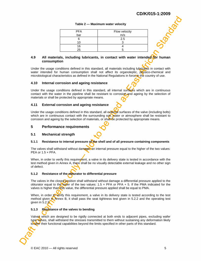
4.6 End types and interchangeability Valves can be designed with various types of end connections adapted to specific pipe systems; the connections shall fulfil the standardized requirements of the relevant pipe systems. In order to ensure interchangeability of flanged valves, their face-to-face or centre-to-face dimensions shall be in accordance with ISO 5752 and their flanges with ISO 7005-1, ISO 7005-2 or ISO 7005-3 (depending on the flange material). In the case of steel valves with welding ends, the end-to-end and centre-to-end dimensions shall be in accordance with ISO 3419. 4.7 Operating direction For valves with an operating mechanism, the preferred direction of closure is clockwise. Valves, other than service connection valves with DN smaller than DN 50, designed for anti-clockwise closure, shall be marked to indicate the closing direction. 4.8 Maximum water velocity Valves shall be designed for water flow velocities which can reach the values given in table 2 in steady flow conditions.
Draf
t for
com
men
ts on
ly —
Not
to b
e cit
ed a
s Eas
t Afri
can
Stan
dard
CD/K/015-1:2009
© EAC 2010 — All rights reserved 5
Table 2 — Maximum water velocity
PFA Flow velocity bar m/s 6 2.5
10 3 16 4 25 5
4.9 All materials, including lubricants, in contact with water intended for human
consumption Under the usage conditions defined in this standard, all materials including lubricants in contact with water intended for human consumption shall not affect its organoleptic, physico-chemical and microbiological characteristics as defined in the National Regulations in force in the country of use. 4.10 Internal corrosion and ageing resistance Under the usage conditions defined in this standard, all internal surfaces which are in continuous contact with the water in the pipeline shall be resistant to corrosion and ageing by the selection of materials or shall be protected by appropriate means. 4.11 External corrosion and ageing resistance Under the usage conditions defined in this standard, all external surfaces of the valve (including bolts) which are in continuous contact with the surrounding soil, water or atmosphere shall be resistant to corrosion and ageing by the selection of materials, or shall be protected by appropriate means. 5 Performance requirements 5.1 Mechanical strength 5.1.1 Resistance to internal pressure of the shell and of all pressure containing components The valves shall withstand without damage, an internal pressure equal to the higher of the two values: PEA or 1.5 × PFA. When, in order to verify this requirement, a valve in its delivery state is tested in accordance with the test method given in Annex A, there shall be no visually detectable external leakage and no other sign of defect. 5.1.2 Resistance of the obturator to differential pressure The valves in the closed position shall withstand without damage a differential pressure applied to the obturator equal to the lower of the two values: 1.5 × PFA or PFA + 5. If the PMA indicated for the valves is higher than this value, the differential pressure applied shall be equal to PMA. When, in order to verify this requirement, a valve in its delivery state is tested according to the test method given in Annex B, it shall pass the seat tightness test given in 5.2.2 and the operating test given in 5.2.3. 5.1.3 Resistance of the valves to bending Valves which are designed to be rigidly connected at both ends to adjacent pipes, excluding wafer type valves, shall withstand the stresses transmitted to them without sustaining any deformation likely to alter their functional capabilities beyond the limits specified in other parts of this standard.
Draf
t for
com
men
ts on
ly —
Not
to b
e cit
ed a
s Eas
t Afri
can
Stan
dard
CD/K/015-1:2009
6 © EAC 2010 — All rights reserved
When, in order to verify this requirement, a valve in its delivery state is tested according to the test method given in annex C with a bending moment M, given in the relevant part of this standard at a differential pressure across the obturator equal to PFA, it shall, under the bending test load: ⎯ show no visually detectable external leakage; ⎯ exhibit a leakage rate at the obturator (see 5.2.2) not higher than that immediately above the
seat leakage rate specified for new valves (e.g., rate B if the specified rate is rate A). 5.1.4 Resistance of valves to operating loads Valves having a mechanically operated obturator shall withstand, in the fully open and in the fully closed positions, the minimum strength torque (mST) without any damage likely to impair their functional capabilities beyond the limits specified in other parts of this standard. The test method, the torques (mST) to be applied and the acceptance criteria shall be those given in the other parts of this standard. 5.2 Leak-tightness 5.2.1 Leak-tightness of the shell and of all pressure containing components 5.2.1.1 Leak-tightness to internal pressure The valves shall be leak-tight under an internal water pressure equal to the higher of the two values: PEA or 1.5 × PFA. When, in order to verify this requirement, a valve in its delivery state is subjected to a water pressure test in accordance with 5.1.1, or to an air pressure test at 6 bar according to ISO 15848-1, there shall be no visually detectable leakage.
NOTE Air testing is applicable only when pressure vessel regulations permit. 5.2.1.2 Leak-tightness to external pressure
Valves shall be leak-tight to ingress of air, water or any foreign matter.
When, in order to verify this requirement, a valve in its delivery state is tested in accordance with the test method given in annex D, any variation of pressure during the test shall not exceed 0.02 bar. 5.2.2 Seat tightness 5.2.2.1 Seat tightness at high differential pressure
The seat of valves in the fully closed position shall be leak-tight within a defined leakage rate, selected from rates A to F of ISO 15848-1 in accordance with the other parts of this standard; the required leakage rate shall be given in the manufacturer's technical data.
When, in order to verify this requirement, a valve in its delivery state is subjected to a test in accordance with A.4 of ISO 15848-1 under a differential pressure equal to 1.1 × PFA for water, or 6 bar for air, the measured leakage rate shall not exceed the defined leakage rate. 5.2.2.2 Seat tightness at low differential pressure Requirement shall be in accordance with 5.2.2.1; test according to 5.2.2.1 but under a differential water pressure of 0.5 bar. 5.2.3 Maximum operating torque (MOT) for operation and leak-tightness Valves having a mechanically operated obturator shall be capable of being opened or closed and made leaktight by application of torques which are compatible with the operating element (lever, handwheel) with which they are equipped or with operating keys generally used for buried valves.
Draf
t for
com
men
ts on
ly —
Not
to b
e cit
ed a
s Eas
t Afri
can
Stan
dard
CD/K/015-1:2009
© EAC 2010 — All rights reserved 7
The maximum operating torques (MOT) and the test method to verify conformance with this requirement shall be those given in other parts of this standard. 5.2.4 Leak-tightness of gearboxes to external pressure Mechanical gearboxes likely to be immersed, shall be designed to avoid any water ingress. They shall be in accordance with EAS 219, class IP 68, with immersion under 3 m head of water for 3 h. 5.3 Hydraulic or airflow characteristics The hydraulic or airflow characteristics of the valves shall be given in the manufacturer's catalogues and shall be in accordance with the other parts of this standard. 5.4 Resistance to disinfection products The functional capabilities of the valves shall not be impaired beyond the limits specified in the other parts of this standard after disinfection has been carried out in accordance with CD/K/004:2009. When, in order to verify this requirement, a valve in its delivery state is tested in accordance with the test method given in annex E, it shall not exhibit any deterioration of its components and it shall pass the seat tightness test in accordance with 5.2.2.1 and 5.2.2.2. The test shall be performed on a valve of a DN which is representative of the range of DNs (same design, same materials) produced by the manufacturer. 5.5 Endurance The endurance of the valves shall be evaluated by means of endurance tests defined in the other parts of this standard. 6 Conformity assessment 6.1 General The conformity of products to the relevant part of this standard shall be demonstrated by: ⎯ carrying out all the type tests (see 6.2) in order to ensure that all fitness for purpose criteria are
met; and, ⎯ controlling the production process (see 6.3) in order to ensure that the required performance
levels are continuously reached. The manufacturer shall ensure that all delivered valves are in accordance with the relevant parts of this standard. Should the verification of a requirement be necessary on a supplied product, it shall be done by carrying out the corresponding type test. 6.2 Type tests The type tests shall comprise the tests corresponding to all the requirements, as given in the relevant part of this standard. Type tests shall be carried out on valves which are representative of the current production. Type tests results shall be recorded in a test report giving the type, quantity, DN and PN of the valves tested and indicating the test apparatus and measuring devices which have been used and their calibration criteria. In order to qualify a range of valves of the same design, manufactured by the same process and from the same materials or equivalent materials, the type tests can be carried out on a limited number of DNs by application of the following rule; when the type tests on one DN have given results in
Draf
t for
com
men
ts on
ly —
Not
to b
e cit
ed a
s Eas
t Afri
can
Stan
dard
CD/K/015-1:2009
8 © EAC 2010 — All rights reserved
accordance with the standard, the two DNs immediately above and the two DNs immediately below are presumed to have passed the same tests. The type tests shall be carried out by the manufacturer or, at his request, by a competent testing institute. Full reports of these tests shall be retained by the manufacturer as evidence of conformity. The appropriate type tests shall be repeated when the design or the production process has been modified in a way likely to negatively affect its functional capacities. 6.3 Control of production process and quality system The manufacturer shall control the quality of his products during manufacture by a system of process control to ensure that the manufactured products meet the performance requirements of this standard. The quality system of the manufacturer shall be in conformity with the requirements of ISO 9001. In addition is it recommended that the quality system be approved by a competent third party certification body. A certification body accredited in accordance with ISO/IEC 17021 will be deemed to be competent. 7 Marking Valves in accordance with this standard shall be marked in a durable and clearly visible manner in accordance with ISO 5209 as follows. ⎯ DN; ⎯ identification of the shell material(s); ⎯ PN; ⎯ identification of the manufacturer; ⎯ identification of the year of manufacture; ⎯ number of the relevant part of this standard e.g. CD/K/015-2. For valves smaller than DN 50, only the three following marks shall be compulsory: ⎯ PN; ⎯ identification of the manufacturer; ⎯ number of the relevant part of this standard e.g. CD/K/015-2. 8 Packaging Valves shall be packaged and/or protected by the manufacturer against mechanical damage and ingress of foreign matter during handling, transport and storage, in accordance with the manufacturer's instructions, except when otherwise agreed between manufacturer and purchaser.
Draf
t for
com
men
ts on
ly —
Not
to b
e cit
ed a
s Eas
t Afri
can
Stan
dard
CD/K/015-1:2009
© EAC 2010 — All rights reserved 9
Annex A
(normative)
Test method for the resistance to internal pressure of the shell and of all pressure containing components
(see 5.1.1) A.1 General A.1.1 Materials with non time dependent mechanical behaviour For shells from such materials (e.g. metals), the test fluid shall be water at any temperature in the range of service temperatures given in 4.4. The test pressure shall be simultaneously applied to the inside of all cavities of the assembled valve, its ends being closed off. If necessary, the obturator shall be in a partially open position. The duration for maintaining the test pressure shall be not less than 10 min. A.1.2 Materials with time dependent mechanical behaviour For shells from such materials (e.g. plastic materials), the fifty year resistance to the pressure given in 5.1.1 shall be demonstrated by type testing with at least one pressure test at ambient temperature and one pressure test at an elevated temperature. Each test shall be carried out with the relevant combination of pressure, temperature and duration, by reference to East African Standards or by agreement between manufacturer and purchaser. The test pressure shall be simultaneously applied to the inside of all cavities of the assembled valve, its ends being closed off. If necessary, the obturator shall be in a partially open position. For on line production tests, the test duration can be fixed by the production cycle, but then the test pressure shall be increased by a factor specific to each material in order to take account of its fifty year extrapolated strength and of its strength regression line (see also 4.5). A.2 Test procedure Close the ends of the valve. Fill the valve with water and vent the air. Raise the pressure until it reaches the test pressure. Maintain the pressure for the specified test duration. Check visually that there is no detectable external leakage and no other sign of defect during the specified test duration. Terminate the test and record the test conditions and test results.
Draf
t for
com
men
ts on
ly —
Not
to b
e cit
ed a
s Eas
t Afri
can
Stan
dard
CD/K/015-1:2009
10 © EAC 2010 — All rights reserved
Annex B (normative)
Test method for the resistance of the obturator to differential pressure
(see 5.1.2) B.1 General B.1.1 Materials with non time dependent mechanical behaviour For shells from such materials (e.g. metals), the test fluid shall be water at any temperature in the range of service temperatures given in 4.4. The test pressure shall be maintained during at least 10 min. The valve shall be in the closed position. The differential test pressure shall be applied successively for each direction of fluid flow unless otherwise specified in the relevant part of this standard. When a valve has a mechanically operated obturator, it shall be closed by application of a torque not exceeding MOT (as defined in the relevant part of this standard). A leak from the seat during the test is not a cause for rejection. B.1.2 Materials with time dependent mechanical behaviour For shells from such materials (e.g. plastic materials), the fifty year resistance to the pressure given in 5.1.2 shall be demonstrated by type testing with at least one pressure test at ambient temperature and one pressure test at an elevated temperature, each test being carried out with the relevant combination of pressure, temperature and duration, by reference to existing standards or by agreement between manufacturer and purchaser. The valve shall be in the closed position. The differential test pressure shall be applied successively for each direction of fluid flow unless otherwise specified in the relevant part of this standard. When a valve has a mechanically operated obturator, it shall be closed by application of a torque not exceeding MOT (as defined in the relevant part of this standard). A leak from the seat during the test is not a cause for rejection. B.2 Test procedure Close one end of the valve. Close the obturator. Fill with water the space between the obturator and one end of the valve, and vent the air. Raise the pressure until it reaches the test pressure.
Maintain the pressure for the required duration (see B.1.1 and B.1.2).
Terminate the test and empty the valve.
For valves designed to be used in both directions, repeat the test with the other end of the valve.
Perform the seat tightness test (see 5.2.2).
For valves having a mechanically operated obturator, perform the operating test (see 5.2.3).
Record the test conditions and test results.
Draf
t for
com
men
ts on
ly —
Not
to b
e cit
ed a
s Eas
t Afri
can
Stan
dard
CD/K/015-1:2009
© EAC 2010 — All rights reserved 11
Annex C
(normative)
Test method for the resistance of valves to bending (see 5.1.3)
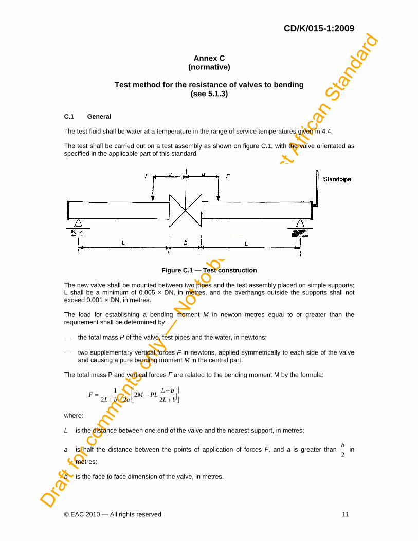
C.1 General The test fluid shall be water at a temperature in the range of service temperatures given in 4.4. The test shall be carried out on a test assembly as shown on figure C.1, with the valve orientated as specified in the applicable part of this standard.
Figure C.1 — Test construction The new valve shall be mounted between two pipes and the test assembly placed on simple supports; L shall be a minimum of 0.005 × DN, in metres, and the overhangs outside the supports shall not exceed 0.001 × DN, in metres. The load for establishing a bending moment M in newton metres equal to or greater than the requirement shall be determined by: ⎯ the total mass P of the valve, test pipes and the water, in newtons; ⎯ two supplementary vertical forces F in newtons, applied symmetrically to each side of the valve
and causing a pure bending moment M in the central part. The total mass P and vertical forces F are related to the bending moment M by the formula:
⎥⎦⎤
⎢⎣⎡
++
−−+
=bLbLPLM
abLF
22
221
where: L is the distance between one end of the valve and the nearest support, in metres;
a is half the distance between the points of application of forces F, and a is greater than 2b in
metres; b is the face to face dimension of the valve, in metres.
Draf
t for
com
men
ts on
ly —
Not
to b
e cit
ed a
s Eas
t Afri
can
Stan
dard
CD/K/015-1:2009
12 © EAC 2010 — All rights reserved
In order to allow a correct measurement of the leakage rate by means of the standpipe, the test assembly, the water and the surrounding atmosphere shall be in thermal equilibrium throughout the test. C.2 Test procedure Position the test assembly on the supports, both ends being closed off. Fill the test assembly with water, the obturator being in a partially open position if applicable, and vent the air. Apply the calculated forces F in order to achieve the bending moment M. If applicable, close the obturator by application of the torque MOT. Raise the pressure in one of the two pipes until it reaches the required test pressure. Maintain the test pressure for a test duration of at least 10 min. Check visually that there is no detectable external leakage for the test duration. At the end of the test, read on the standpipe the amount of water that has leaked from the pressurized pipe to the unpressurized pipe and calculate the leakage rate. Release the forces F and the pressure and terminate the test. For valves designed to be used in both directions, repeat the test by pressurizing the other pipe. Record the test conditions and test results.
Draf
t for
com
men
ts on
ly —
Not
to b
e cit
ed a
s Eas
t Afri
can
Stan
dard
CD/K/015-1:2009
© EAC 2010 — All rights reserved 13
Annex D
(normative)
Minimal test method for the leak-tightness to external pressure of the shell and all pressure containing components
(see 5.2.1.2) D.1 General The valve to be tested shall be free from water. The test shall be carried out at ambient temperature. D.2 Test procedure Operate the obturator at least five times (from fully open to fully closed and back). Set the obturator in a partially open position. Close the ends of the valve. Lower the pressure in the valve to -0.8 ± 0.02 bar relative. Isolate the valve from the vacuum pump for 2 h, with the valve temperature constant within ± 2° C. Note the internal pressure at the end of the 2 h and calculate the pressure variation with respect to the initial pressure. Record the test conditions and test results.
Draf
t for
com
men
ts on
ly —
Not
to b
e cit
ed a
s Eas
t Afri
can
Stan
dard
CD/K/015-1:2009
14 © EAC 2010 — All rights reserved
Annex E
(normative)
Test method for the resistance to disinfection products (see 5.4)
E.1 General The test shall be carried out at ambient temperature. The test solution shall be an aqueous solution of NaCIO or Ca(CIO)2 containing 50 mg/l of active chlorine (expressed as CI2). E.2 Test procedure Close the ends of the valve. Set the obturator in a partially open position. Fill the valve with the test solution and vent the air. Let the valve stand for 48 h. Empty the valve and inspect visually to detect any deterioration of its components. Perform the seat tightness test (see 5.2.2). Record the test conditions and test results.

Draf
t for
com
men
ts on
ly —
Not
to b
e cit
ed a
s Eas
t Afri
can
Stan
dard
CD/K/015-1:2009
© EAC 2010 — All rights reserved