eclipse service - 380 stron
DESCRIPTION
Informacje techniczneECLIPSEw miare czyste do drukowaniaTRANSCRIPT

Informacje techniczne
ECLIPSE

ECLIPSE
Informacje Ogólne .................................... . . . . . . . . . . . . . . . .. . . . . 000
techniczne Silnik... . . . . . . . . . . . . . . . . . . . . . . . . . . . . . . . . . . . . . . . . . .
I
Wprowadzenie
Moc.............. . . . . . . . . . . . . . . . . . . . . . . . . . . . . . . m
Zewnetrzne komponenty kont.... ...m
Jednostka . . . . . . . . . . . . . . . . . . . . . . . . . . . . . . . . . . . . . . 0
A
Zewnetrzne. ......................................
Wnetrze. ..............................................
Wyposarzenie. ...................................
EQUIPMENT . . . . . . . . . . . ....................
Mitsubishi Motors Corporation reserves the right to make changes in design or to make additions to or improvements in its products without imposing any obligations upon itself to install them on its products previously manufactured.0 1994 Mitsubishi Motors Corporation Printed in U.S.A.
Niniejszy podrÿcznik zostaÿ przygotowany jak wprowadzenie na temat technicznych odnoÿnie do nowo opracowane eclipse

MODEL INDICATIONS
The following abbreviations are used in this manual for classification of model types.M/T: Indicates the manual transaxle, or models equipped with the manual transaxle.A/T: Indicates the automatic transaxle, or models equipped with the automatic transaxle.MFI:DOHC:
Indicates the multiport fuel injection, or engines equipped with the multi-point injection.Indicates an engine with the double overhead camshaft, or a model equipped with suchan engine.
Turbo: Indicates an engine with turbocharger, or a model equipped with such an engine.Non-Turbo:FWD:
Indicates an engine without turbocharger, or a model equipped with such and engine.Indicates the front wheel-drive vehicles.
AWD: Indicates the all wheel-drive vehicles.
HOW TO READ A CIRCUIT DIAGRAM Circuit diagrams are prepared as follows using thesesymbols:
NOTEFor specific details concerning the interpretationof circuit diagrams, refer to the separately boundService Manual.
Indicates power take out. Indicates input/output to/from
Ilp~x+connector. I\ ‘Y-.W:
A broken line indicates thatthese connectors are the same :’ e j;/ :, *intermediate connectors.
\
The connector symbolindicates the deviceside connector (for anintermediate connec-tor, the male side con-nector) as seen fromthe terminal front (theconnector’s connec-
IOutput Input/
Input , , I o u t p u t I
Indicates terminal No.
Indicates current flow downward or
t j upward as controlled by the control,._ u n i t .
Indicates harness junction where

o-1
GENERALCONTENTS
DESIGN FEATURES . . . . . . . . . . . . . . . . . . . . . . . . 3
GENERAL DATA AND SPECIFICATIONS . . . 17
TARGETS OF DEVELOPMENT . . . . . . . . . . . . . . 2
TECHNICAL FEATURES . . . . . . . . . . . . . . . . . . . . 4
Aerodynamic Characteristics . . . . . . . . . . . . . . . . . . . 5Body Dimensions . . . . . . . . . . . . . . . . . . . . . . . . . . . . . 4Engine . . . . . . . . . . . . . . . . . . . . . . . . . . . . . . . . . . . . . . . .
L Environmental Considerations . . . . . . . . . . . . . . . . . 12Heater and Air Conditioning . . . . . . . . . . . . . . . . . . 12Passive Safety . . . . . . . . . . . . . . . . . . . . . . . . . . . . . . . 10
Steering Stability, Ride Comfort andActive Safety . . . . . . . . . . . . . . . . . . . . . . . . . . . . . . . . . 8Theft-alarm System . . . . . . . . . . . . . . . . . . . . . . . . . . 11
VEHICLE IDENTIFICATION . . . . . . . . . . . . . . . . . 14
Engine Model Stamping . . . . . . . . . . . . . . . . . . . . . . 16Vehicle Identification Code Chart Plate . . . . . . . . 14Vehicle Identification Number List . . . . . . . . . . . . . 14Vehicle Identification Number Location . . . . . . . . . 14Vehicle Information Code Plate . . . . . . . . . . . . . . . . 15Vehicle Safety Certification Label . . . . . . . . . . . . . . 15

o-2 GENERAL - Targets of Development
TARGETS OF DEVELOPMENTWhile the ECLIPSE has been finding wide accep-tance as a compact sporty vehicle since its introduc-tion early in 1989, Mitsubishi Motors Corporationhas introduced further improvements with major ac-cent on the following points to meet the marketneeds and make the ECLIPSE a top car in its class.l Styling
1. Organic and aerodynamic.2. Wide and low proportions.
l Fun to drive1. Quick acceleration and powerful response
(All models equipped with DOHC engine)2. Outstanding straight ahead stability and lin-
ear steering response (4-wheel multi-linksuspension adopted)
3. Outstanding braking performance0 Va lue fo r money
1. Rich array of features at low price2. Low fuel consumption and low repair cost

GENERAL - Design Features
DESIGN FEATURES
bUnique styling
l Forward extended cabin for roomy cabin and sporty stylingl Wide and low proportion bodyl Aerodynamic oriented styling
New techniquesw l Chrysler-manufactured 2.0 lit. DOHC engine (420A en-
gine)l Multi-link suspension for both front and rearl Motor-driven outer slide type glass sunroof
Higher safetyt
D 0 Passive safety featuresSRS (for driver and front passenger), side door beams,8 km/h (5 mph) resin bumper beams, flame-retardantupholstery, etc.
l Active safetv features
Aerodynamic + l World’s top level Cd = 0.29characteristics

GENERAL - Technical Features
TECHNICAL FEATURESBODY DIMENSIONSExternal Dimensions
Internal Dimensions
5, 6 *
Items No. New model
mm (in.)
Difference betweenprevious andnew models
Overall Length 1 4,375 (172.2) -15 (-59)
Overall Width 2 1,735 (68.3)1,745 (68.7)*’
+40 (+1.57)+50 (+1.97)“’
Externaldimensions
Overall Height
Wheelbase
Tread (front)
Tread (rear)
Overhang (front)
Overhang (rear)
3 1,295 (51.0)1,310 (51 .6)*2
-11 (-.43)-4 (-. 15)*2
4 2,510 (98.8) +40 (+1.57)
5 1,515 (59.6) +50 (+1.97)
8 1,510 (59.4) +60 (+2.36)
7 930 (36.6) -45 (-1.77)
8 935 (38.8) -10 (-.39)
NOTES*l denotes a vehicles with side air dam.*2 denotes AWD.

GENERAL - Technical Features o-5
Items No. New modelDifference between
previous andnew models
Head Room 8 (front) 9 860 (33.9) 0
Head Room 8 (rear) 10 785 (30.1) 0
Internal Brake Pedal Room 11 940 (37.0) +15 (+.59)
dimensions Hip Point Couple 12 635 (25.0) 0
Front Hat Room 13 1,080 (41.7) 0
Front Hip Point Couple 14 714 (28.1) 0
AERODYNAMIC CHARACTERISTICSMany Cd reduction design features, including taper-ing at body corners, has raised ECLIPSE’s aerody-
namic characteristics to the top level of the class(Cd = 0.29).
\ \ /0 0 6
@ Tapered front side corners@I Tapered rear pillar area0 Tapered rear side corners@ S$;ted and rounded engine hood
0 Smaller rear window inclinationangle for smoother air flow
0 Venturi skirt0 Smoother and more flush under-
floor surface$3 Raised rear floor plane
Greater contribution to fuel econo-

O-6 GENERAL - Technical Features
ENGINETwo basic DOHC engines are available.
420A Engine
On non-turbocharged models, the Chrysler-manufactured 2.0 lit. DOHC 16-valve engine in-creases domestic parts content. The engine and
transaxle unit, unlike the conventional MMC engine,is arranged with the engine on the passenger sideand the transaxle on the driver’s side.
4G63 Engine
On turbocharged models, new techniques and im-provements have been embodied in the 4G63 en-
gine to provide better performance and lower fuelconsumption.
NEW TECHNIQUES AND IMPROVEMENTS
Aims
Items Smaller size Higher Higher de- Tighter ex-performance Less noise Resource pendability haust emis-
and lighter and and energy and easier sion controlweight efficiency saving mainte- and better
nance driveability
Higher compression ratio X X
Better turbocharger performance X
Small-size pressure type Karman airflow sensor adopted X X
Higher intercooler efficiency X X
Cylinder head intake port is tumble-type
X X X
2-spray injector adopted X X X
Optimized injector direction and tim-ing X X X
Engine coolant temperature inletcontrol system X X
48 Kbyte computer adopted X X
Resonance type knock sensoradopted X X X
Stainless steel exhaust manifoldadopted X
Dual oxygen sensor systemadopted X
Oxygen sensor mounted to front ex-haust pipe X
Piston top land height reduced X
ECM-controlled EGR adopted X
ECM-controlled fuel vapor controlsystem adopted X
Generator control improved X
NOTE:x : Applicable

GENERAL - Technical Features o-7T 1Aims
Higher per-formance
andefficiency
Higher de- Tighter ex-Resource pendability haust emis-
Less noise and energy and easier sion controlsaving mainte- and better
nance driveability
Items Smaller sizeand lighter
weight
Cooling fan controlled by ECM(Total Control System) X
Integrated control of A/T X X
Higher accuracy coolant tempera-ture sensor X X X
Crank angle sensor using Hall ICdirectly mounted to crankshaft X X
Cylinder block reinforced X
X
X X
X
Turbocharger piping revised
Small-size and light-weight aircleaner made of resin which allowsthe air to pass with less resistance
X
Dual mode damper
Air bypass valve position optimized XI I IPower steering belt changed to V
ribbed style rOil level gauge grip changed toresin
Scan tool (MUT-II) compatible
IVOTE:x : Applicable

O-8 GENERAL - Technical Features
STEERING STABILITY, RIDE COMFORT AND ACTIVE SAFETYMulti-link Suspension for Four WheelsA multi-link suspension similar to the 1994 Galant’s,has been adopted for both the front and rear wheels.
and stability have significantly improved, assuring d
As a result, the straight line running characteristicsoutstanding directional stability without penalty onriding comfort.
Shock absorber
Lateral lowe; arm\
dY
%ti
Upper arm
Coil spring-‘r 0
Toe controlarm \
Shock absorber
Lower arm 5 \yg&!!
’Trailing arm

GENERAL - Technical Features O-9ABS
ii
ABS is an option for all models to improve braking (Select Low control) of the rear wheels. For AWDstability and safety. vehicles, the 4-sensor, 2-channel configuration isFor the FWD vehicles, the 4-sensor, 3-channel con- adopted for Select Low control of all the front andfiguration is adopted for independent control of the rear wheels.front right and left wheels and integrated control
<FWD>
i
ABS warning Data linkconnector Wheel speed sensor (RR)
Electronic lightcontrol unit (ECU)
\ \
\
Aheel speed2:;’ sensor (F.L.)
ABS Datalink connector
unit 0-U relay

O-IO GENERAL - Technical Features
PASSIVE SAFETYSupplemental Restraint System (SRS)An airbag module has been provided for both thedriver’s and front passenger’s seats for safety ofthe driver and front passenger. The driver’s seatairbag module is mounted at the center of the steer-
ing wheel, whereas the front passenger’s seat airbagmodule is mounted in the instrument panel abovethe glove compartment. As soon as a frontal collisionover a design G-force is detected, the airbags inflate.
Data link connector
Left front impact
Air bag module(Passenger’s side)
Air baa module \(Drive& side)
L-d---
Plastic fuel tank
The AWD models are equipped with a plastic fuel tank whichis highly resistant to shocks and offers good space efficiency.The fuel tank is installed under the floor for higher safety.
Flame-retardant upholstery
Flame-retardant materials have been used for interior uphol-stery wherever possible.

GENERAL - Technical Features O-II
THEFT-ALARM SYSTEM
LFor theft protection, this system is so designed that Furthermore, the starter circuit is interrupted so thatthe headlights go on and off and the horn is sounded the engine may not be operated.intermittently for about three minutes when a lockeddoor, hood or liftgate has been forced open withoutusing a key.
sr DAbout 20 seconds after all doors are closed andlocked, the liftgate is closed, and the hood isclosed + SYSTEM ARMED
ligtgate or hood is broken to
Engine is disabled and will not start.
Driver opens door with the key
ISYSTEM DISARMED
t-!a- Normal starting -1 ti D Driver unlocks a door or liftgate with the key.
ALARM DEACTIVATED(SYSTEM DISARMED)

o-12 GENERAL - Technical Features
HEATER AND AIR CONDITIONINGThe heater system uses a two-way-flow full-air-mix The air conditioning system is essentially the samesystem that features high performance and low oper- as the conventional one, but it incorporates a new dating noise, and includes an independent face air CFC-free refrigerant (R134a) system that uses hy-blowing function and a cool air bypass function. dro fluorocarbon (HFC) containing hydrogen atomsSide defrosters have been provided in the door sec- as the refrigerant gas to meet the CFC control regu-tion to improve demister performance. lations that call for protection of the ozone layer.For the rear seat, a semi rear heater duct has beenprovided for better heating.
Side defroster
Inside air
M~~~~~ Wrao coolerII40
A. ,,,.:.4... -:r FACE independent
c3
0
c3nter outlet
Blowe; assembly Shut dar;?per
e- Semi rear heater
ENVIRONMENTAL CONSIDERATIONSTo meet the growing world-wide demands for savingresources and protecting global environment, spe-cial considerations have been incorporated to makethe ECLIPSE friendly to driver and passengers andto the earth.
Considerations for recycling
(1) Recyclable thermo-plastic material has beenextensively used.
(2) The names of the material have been markedon the plastic parts to facilitate recycling.
(3) Recycled materials (regenerated materials)have been used wherever possible.
air flow
Protection of global environment
(1) Use of non-asbestos material for gaskets andpads
(2) Non-Freon partsl Use of Freon has been limited to the neces-
sary minimum in the processes for manufac-ture of seats, steering wheels, etc.
(3) Extending material life expectancies for lesswastel Anti-rust steel sheets have been used for
about 80% of the outer panels and majormembers of the body.
l Longer-life brake fluid and coolant additivesare used
(4) Better fuel economy by reducing friction andweight in various areas

GENERAL - Technical Features o-13
Use of maintenance-free parts
i(1) Auto-lash adjusters have eliminated the need
for adjustment of valve clearance.(2) An auto-tensioner has been adopted to elimi-
nate the need for adjustment of the timing belttension.
(3) The improved mounting accuracies of the cam-shaft position sensor and crank angle sensor
Increased diagnostic items
The diagnostic functions for the following systemhave been added so that the diagnostic troublecodes and service data for them can be read andactuator tests performed by use of the Scan tool(MUT-II).
Better serviceability and easier handling
(1) The engine oil and ATF level gauge grips havebeen changed to resin ones for easier handling.The name has been marked on each grip foridentification.
(2) The fuel gauge unit and related parts have beenmade demountable and remountable throughthe service hole under the rear seat cushion.
(3) Both the front and rear hubs have been boltedto the knuckles for easier demounting and re-
L-Jmounting.
(4) When an ABS wheel speed sensor is mounted,there is no need for adjustment of the clearancebetween the sensor and rotor.
have eliminated the need for adjustment of igni-tion timing.
(4) The plastic region angle method has beenadopted for tightening the cylinder head bolts.
l MFIl *Auto-cruise control. ELCQAIT. ABS. SRS
(5) Headlight aiming adjustment can be easily per-formed from above the light, using a cross-pointed screwdriver.
(6) An electric type speedometer has been adoptedfor easier demounting and remounting of thespeedometer, instrument panel, transaxle, etc.
(7) The luggage compartment floor board can beheld raised so that the spare wheel, tools, etc.can be conveniently taken out and stored.

GENERAL - Vehicle Identification
I\\ 1 VEHICLE IDENTIFICATIONVEHICLE IDENTIFICATIONVEHICLE IDENTIFICATION NUMBER LOCATION VEHICLE IDENTIFICATION NUMBER LOCATION The vehicle identification number (V.1.N) is located on a plateThe vehicle identification number (V.1.N) is located on a plateattached to the left top side of the instrument panel.attached to the left top side of the instrument panel.
VEHICLE IDENTIFICATION CODE CHART PLATE
All vehicle identification numbers contain 17 digits. The vehiclenumber is a code which tells country, make, vehicle type,erc.
12th to17th Digits
Serialnumber
000001
99~99
9thDigit I
4thDigit
6thDigit
10thDigit
11thDigit
3rdDigit
Vehicle type
5thDigit
7thDigit
8thDigit
EngineOthers Line ‘Checkdigits
Modelyear PlantPrice class
3-Medium
4-High
5-Premium
Body
I-3-doorHatch-back
S - E --T--1995 DSM PlantYear
3-Passengercar
A-Driver andPassengerAir Bags
K-ECLIPSEF W D
L-ECLIPSEAWD
Y-2.0 dms(122.0cu.in.)[DOHC-MFI]
F-2.0 dms(122.0cu.in.)[DOHC-MFI-Turbo]
Mitsubishi
L
NOTEl “Check digit” means a single number or letter X used to verify the accuracy of transcription of vehicle identification number.
VEHICLE IDENTIFICATION NUMBER LIST 4995 MODEL>VEHICLES FOR FEDERAL
V.I.N.(except sequence number)
4A3AK34YOSE
4A3AK44YUSE
Brand
Mitsubishi EclipsecFWD>
4A3AK54SDSE Mitsubishi Eclipse<FWD>
4A3AL54SOSE Mitsubishi Eclipse<AWD>
Engine Displacement Model Code
2.0 dm3 (122.0 cu.in.)[DOHC-MFI (420A)]
D31AMNJML4MD31AMRJML4M
D31 AMNHML4MD31AMRHML4M
2.0 dm3 (122.0 cu.in.)[DOHC-MFI-Turbo (4G63)]
D32AMNGFL4MD32AMRGFL4M
D33AMNGFL4MD33AMRGFL4M

GENERAL - Vehicle Identification o-15
VEHICLES FOR CALIFORNIA
V.I.N.(except sequence number)
Brand Engine Displacement Model Code
4A3AK34YOSE
4A3KF44YOSEi
Mitsubishi Eclipse<FWD>
2.0 dm3 (122.0 cu.in.)[DOHC-MFI (420A)]
D31 AMNJMLSMD31 AMRJMLSMl-----lD31 AMNHMLSMD31AMRHMLSM
4A3AK54SCiSE Mitsubishi Eclipse<FWD>
2.0 dm3 (122.0 cu.in.)[DOHC-MFI-Turbo (4G63)]
D32AMNGFLSMD32AMRGFLSM
4A3AL54SOSE Mitsubishi Eclipse<AWD> I
D33AMNGFLSMD33AMRGFLSM I
VEHICLE INFORMATION CODE PLATEVehicle information code plate is riveted onto the bulkheadin the engine compartment.The place shows model code, engine model, transaxle model,and body color code.
1. MODEL D32AM RGFL4M
L !$$z,edsel2. ENGINE 4 G 6 3
L Engine model
3. EXT CAGA
( Exterior code
4. TRANS F4A33
I Transaxle model
5. COLOR TRIM R25 67V 03V
OPT -p=~~~~~~
VEHICLE SAFETY CERTIFICATION LABEL
1. The vehicle safety certification label is attached to faceof left door pillar.
2. This label indicates Gross Vehicle Weight Rating(G.V.W.R.), Gross Axle Weight Rating (G.A.W.R.) front,rear and Vehicle Identification Number (V.I.N.).

O-16 GENERAL - Vehicle Identification
ENGINE MODEL ST2 PINGM’r1. The engine model numbe is stamped at the front side
on the top edge of the cylinder block as shown in thefollowing.
I Engine model I Engine displacement
420A I 2.0 dm3 (122.0 cu.in.)I I
4G63 2.0 dm3 (122.0 cu.in.)
2. The 4G63 engine serial number is stamped near the enginemodel number, and the serial number cycles, as shownbelow.
Engine serial number
AA0201 to YY9999
Number cycling
BAOOOl - - -w YY9999
3. The 420A engine serial number and identification numberare stamped near the engine model number.

GENERAL - General Data and SDecifications o-17
i
GENERAL DATA AND SPECIFICATIONS
L
GENERAL SPECIFICATIONS<FWD>
11
6-I
1;; z;,
Model code D31A D32A
MNJML4M MRJML4M MNHML4M MRHML4M MNGFL4M MNGFL4MMNJMLSM MRJMLSM MNHMLSM MRHMLSM MNGFLSM MNGFLSM
Vehicle dimensions mm (in.)Overall length 1 4,375 (172.2)
Overall width 2 1,735 (68.3), 1,745 (68.7)*3 1,745 (68.7)
Overall height (Unladen) 3 1,295 (51 .O)
Wheel base 4 2,510 (98.8)
Tread Front 5 1,515 (59.6)
Rear 6 1,510 (59.4)
Overhang Front 7 930 (36.6)
Rear 8 935 (36.8)
Minimum running ground 9 145 (5.7)clearance
Angle of approach degrees 10 11.5
Angle of departure degrees 11 15.8
Vehicle weight kg (Ibs.)Curb weights 1,235 1,270 1,280 1,315 1,305 1,340
(2,722) (2,800) (2,822) (2,899) (2,877) (2,954)Gross vehicle weight rating 1,690 (3,726) 1,750 (3,858)
Gross axle weight ratingFront 1 ,010 (2,227) 1,025 (2,260)Rear 800 (1,764) 775 (1,709)
Seating capacity 4
EngineModel No. 420A (DOHC) 4G63 (DOHC)Piston displacement cm3 (cu.in.) 1,996 (121.8) 1,997 (121.9)
TransaxleModel No. F5MCl F4ACl F5MCl F4ACl F5M33 F4A33Type 5-speed 4-speed 5-speed 4-speed 5-speed 4-speed
manual automatic manual automatic manual automatic
Fuel systemFuel supply system Electronic control multiport fuel injection
NOTEl 3 denotes a vehicles with side air dam.
GENERAL - General Data and Specifications
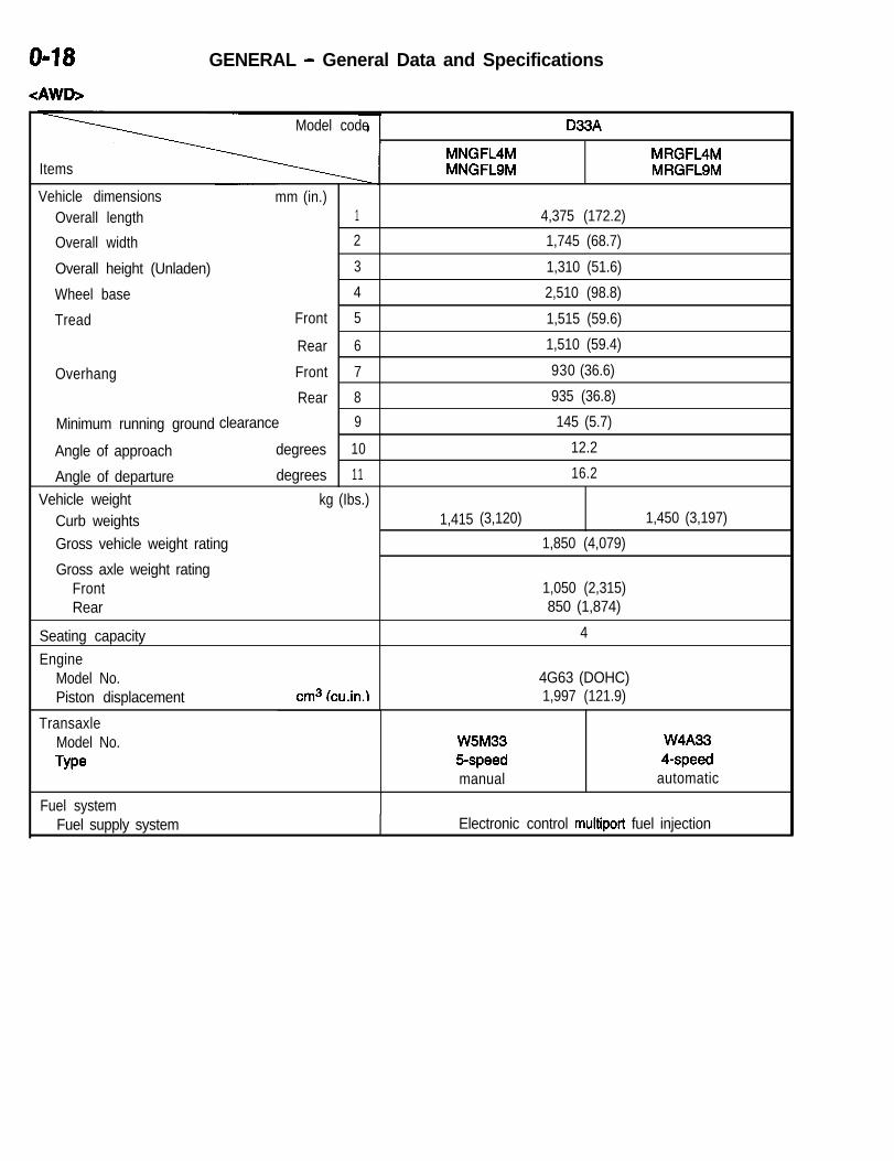
<:AWD>
Model code
Items
Vehicle dimensions mm (in.)Overall length 1
Overall width 2
Overall height (Unladen) 3
Wheel base 4
Tread Front 5
Rear 6
Overhang Front 7
Rear 8
Minimum running ground clearance 9
Angle of approach degrees 10
Angle of departure degrees 11
Vehicle weight kg (Ibs.)Curb weightsGross vehicle weight rating
Gross axle weight ratingFrontRear
Seating capacityEngine
Model No.Piston displacement cm3 (cu.in.1
D33A
MNGFL4M MRGFL4MMNGFLSM MRGFLSM
4,375 (172.2)
1,745 (68.7)
1,310 (51.6)
2,510 (98.8)
1,515 (59.6)
1,510 (59.4)
930 (36.6)
935 (36.8)
145 (5.7)
12.2
16.2
1,415 (3,120) 1,450 (3,197)
1,850 (4,079)
1,050 (2,315)850 (1,874)
4
4G63 (DOHC)1,997 (121.9)
TransaxleModel No.Type
Fuel system
W5M33 W4A335-speed 4-speedmanual automatic
Fuel supply system Electronic control multiport fuel injection

1-I
ENGINECONTENTS N7lZAOOM
ENGINE <NON-TURBO> . . . . . . . . . . . . . . . . . . . . 2ACCELERATION SYSTEM . . . . . . . . . . . . . . . . . . . . . . . . . . . 62
Accelerator Pedal and Accelerator Cable .................. 62Auto-cruise Control System ............................... 63
BASE ENGINE . . . . . . . . . . . . . . . . . . . . . . . . . . . . . . . . . . . . . . . 3
Automatic Tensioner ......................................5Camshaft ................................................4Connecting Rods .........................................4Crankshaft.. .............................................4Crankshaft and Camshaft Timing .......................... 5Cylinder Block and Bed-plate .............................. 3Cylinder Head ............................................3Oil Pan ..................................................7Oil Pump ................................................7Piston ...................................................3
CONTROL SYSTEM . . . . . . . . . . . . . . . . . . . . . . . . . . . . . . . . . 13
Actuators and Control ....................................26Data Transmission System.. .............................. 52Diagnostic System .......................................31General Information ......................................13Sensors ................................................ 16
COOLING SYSTEM . . . . . . . . . . . . . . . . . . . . . . . . . . . . . . . . . . . 6
Coolant Flow .............................................8Specifications ............................................9
EMISSION CONTROL SYSTEM . . . . . . . . . . . . . . . . . . . . . . . 57Evaporative Emission Control System ...................... 59Exhaust Gas Recirculation (EGR) System ................. 60General Information ...................................... 57Positive Crankcase Ventilation System ..................... 58Pulsed Secondary Air Injection System .................... 59
ENGINE ELECTRICAL . . . . . . . . . . . . . . . . . . . . . . . . . . . . . . . 56
Generator ...............................................56Ignition System..........................................5 6Starter Motor............................................5 6
FUEL SYSTEM . . . . . . . . . . . . . . . . . . . . . . . . . . . . . . . . . . . . . . 11
Configuration Diagram ................................... 11Fuel Flow Diagram ...................................... 11
Fuel Tank...............................................12GENERAL INFORMATION . . . . . . . . . . . . . . . . . . . . . . . . . . . . 2
Lubrication System ....................................... 2Major Specifications ...................................... 2
INTAKE, AND EXHAUST . . . . . . . . . . . . . . . . . . . . . . . . . . . . . 10
Exhaust Pipe ...........................................10Intake Manifold and Exhaust Manifold ..................... 10
MOUNT . . . . . . . . . . . . . . . . . . . . . . . . . . . . . . . . . . . . . . . . . . . . . 61Features.. ..............................................61
ENGINE <TURBO> . . . . . . . . . . . . . . . . . . . . . . . . 64ACCELERATION SYSTEM . . . . . . . . . . . . . . . . . . . . . . . . . . . 68
Accelerator Pedal and Accelerator Cable .................. 88Auto-cruise Control System ............................... 88
CONTROL SYSTEM . . . . . . . . . . . . . . . . . . . . . . . . . . . . . . . . . 70
Actuators and Control ..................................... 74Diagnostic System ....................................... 78General Information ...................................... 70Main monitors...........................................8 3Sensors ................................................7 3
COOLING SYSTEM . . . . . . . . . . . . . . . . . . . . . . . . . . . . . . . . . . 65Coolant FLOW............................................ 5Specifications ......................................... ..6 6
EMISSION CONTROL SYSTEM . . . . . . . . . . . . . . . . . . . . . . 85
Exhaust Gas Recirculation (EGR) System ................. 86General Information ........................... : ........... 85
ENGINE ELECTRICAL. .
. . . . . . . . . . . . . . . . . . . . . . . . . . . . . . . 85
F U E L SYSTEM. . . . . . . . . . . . . . . . . . . . . . . . . . . . . . . . . . . . . . . 68
Configuration Diagram ................................... 68Fuel Flow Diagram ...................................... 68Fuel Tank...............................................6 9
GENERAL INFORMATION . . . . . . . . . . . . . . . . . . . . . . . . . . . 64
Major Specifications ..................................... 84INTAKE AND EXHAUST . . . . . . . . . . . . . . . . . . . . . . . . . . . . . 67
Exhaust Pipe ........................................... 67Intake Manifold and Exhaust Manifold ..................... 67
MOUNT . . . . . . . . . . . . . . . . . . . . . . . . . . . . . . . . . . . . . . . . . . . . . 87

ENGINE <NON-TURBO> - General Information
ENGINE <NON-TURBO>
GENERAL INFORMATIONThis 420A 2.0-liter engine is a product of Chrysler Corporation. It is not equipped with a turbocharger.
MAJOR SPECIFICATIONS
Items Specifications
Total displacement cm3 (cu.in.) 1,996 (121.8)
Bore x Stroke mm (in.) 87.5 (3.45) x 83.0 (3.27)
Compression ratio 9.6
Camshaft arrangement DOHC
Valve timing At 0.5 mm (.0197 in.) liftIntake
Open 1.3” BTDCClose 39.7” ABDC
ExhaustOpen 36” BBDCClose 1.1” ATDC
Rocker arm Roller type
Lash adjuster Equipped
LUBRICATION SYSTEMSystem is full flow filtration, pressure feed type.The oil pump is mounted in the front engine cover
cated from rod bearing throw-off and slinger slots
and driven by the crankshaft. Pressurized oil is thenon the connecting rod assemblies. Camshaft and
routed through the main oil gallery, running thevalve mechanisms are lubricated from a full-length
length of the cylinder block, supplying main andcylinder head oil gallery supplied from the crankcasemain oil gallery.
rod bearings with further routing. Pistons are lubri-

ENGINE <NON-TURBO> - Base Engine l-3
BASE ENGINECYLINDER HEADFeatures a Dual Over Head Camshaft (DOHC)4-valves per cylinder cross flow design. The valvesare arranged in two inline banks. Incorporated pow-
CYLINDER BLOCK AND BED-PLATEFive different engine designs were considered, theonly engine design that met all the criteria was onethat utilized a bed-plate. There are several forcesat work in the lower end of an engine block.These are:l Vertical bendingl Horizontal bending - 90 degrees to the cylinder
borel Torsional bending along the crankshaft axisl Individual main cap flutter co-inciding to indi-
vidual cylinder firingAll these factors contribute to noise, vibration andharshness. Because this is a four cylinder engine,design criteria becomes even more important. Bed-
PISTONThe piston has an oval shape (elliptical) that expandsas the engine warms-up. This reduces cold engine
idpiston noise, helps the piston fit into the bore betterand avoids piston scuffing.The piston pin has a 1 mm (.0394 in.) offset towardthe thrust side of the piston for improved noise char-acteristics. The top ring is a steel unit with a plasmasprayed molybdenum faced center section for reli-able compression sealing. The upper ring is notdirectional. The black coating as a rust preventative.A taper faced cast iron second compression ring
der metal valve guides and seats. Integral oil galleyswithin the cylinder head supplies oil to the hydrauliclash adjusters, camshaft and valve mechanisms.
plate design makes for a much stronger lower endbecause it ties all of the main caps together to sub-stantially improve block stiffness. The block is atwo-piece assembly, encompassing the bed-plateand the cylinder block. The bed-plate is made ofcast iron and is totally separable from the block.When installed, it becomes part of the block andstrengthens the lower end considerably. The bed-plate and block are cast separately, then machinedtogether. Once machined, the bed-plate and blockare drilled and doweled together to become a matedunit. This ensures that the bed-plate and block arein perfect alignment even after assembly and disas-sembly.
is used for additional cylinder compression control.Both compression rings are 1.2 mm (.0472 in.) thick.The oil ring is a three piece design using chromefaced fails and a separate center expander. Usethe running clearance notches and is identifiableby a slight dish at the top of the piston.This engine is pressed-in piston pins to attach forgedpowder metal connecting rods. Incorporate hex headcap screw threaded into the connecting rod. Pistonand Rods are serviced as an assembly.
I /No. 1 piston ring
N o . 2 p i s t o n r i n gJ 1 1 \
Siderail
extender Oil ring
ENGINE <NON-TURBO> - Base Engine
CONNECTING RODSThe connecting rods are different from past designsbecause the manufacturing process has changed.The connecting rod is forged as one piece frompowdered metal. The powdered metal is placedin a form that is slightly oversized and then sentto sintering furnace. It melts the powdered metalin the mold. The mold travels to a forging presswhere the rod is forged to the final shape. Thisis done while the rod is still warm, but not molten.After the forging process, the inside diameter ofthe crankshaft end of the rod is scribed with a laserand is fractured in a fixture. This creates a rod capand rod that only fit together one way. The finalstep in the process is shot peening which increases
CAMSHAFTThe camshafts have six bearing journals and 2 camlobes per cylinder. Flanges at the rear journals con-trol camshaft end play. Provision for cam position
CRANKSHAFTThe engine has 5 main bearings, with number 3flanged to control thrust. The 52 mm (2.0472 in.)diameter main and 48 mm (1.8898 in.) diametercrank pin journals (all) have undercut fillets thatare deep rolled for added strength. To evenly distrib-ute bearing loads and minimize internal stress, 8counterweights are used. Hydrodynamic seals pro-
the surface hardness slightly. This design processeliminates the need for several machining opera-tions that are required for cast iron, connecting rodassemblies. Other designs required machining theconnecting rod and connecting rod cap individually,then finish machining, honing, and balancing areperformed as an assembly.NoteThe new process and the different metal does notprohibit the use of standard tools. If the connectingrods require removal from the engine a center punchcan be used to identify the correct position of theconnecting rod and cap.
sensor on the exhaust camshaft at the rear of cylin-der head. A hydrodynamic oil seal is used for oilcontrol at the front of the camshaft.
vide end sealing, where the crankshaft exits theblock. Anaerobic gasket material is used for partingline sealing in the block. A sintered powder metaltiming belt sprocket is mounted on the crankshaftnose. This sprocket provides motive power; via tim-ing belt to the camshaft sprockets (providing timedvalve actuation) and to the water pump.

ENGINE <NON-TURBO> - Base Engine I-5
CRANKSHAFT AND CAMSHAFT TIMING
LThis engine does not have broken-belt valve clear-ance. The reason for this design is to improve hydro-carbon emissions by eliminating valve pockets cutinto the pistons that would normally provide thisclearance. If the engine is rotated with the timingbelt removed or the cam timing is set improperly,the valves will hit the pistons. However, if the cam-
AUTOMATIC TENSIONERThis engine uses a timing-belt cover, crankshaftsprocket, timing belt, “automatic” belt tensioner, twocamshafts, and camshaft sprockets. The belt ten-sioner is spring activated, hydraulically dampened,and self contained. The tensioner consists of a freepiston, orifice, silicone fluid, a spring, check ball,and a plunger rod. The check ball is seated asthe plunger rod is depressed, trapping the fluid and
shafts are out of time on engines, the valves canstrike each other as well as the pistons. This isdue to the intake and exhaust valve-to-valve interfer-ence design. Therefore, it is necessary to time thecamshafts and crankshaft simultaneously to preventdamage to pistons, exhaust valves, and intakevalves.
creating a high pressure area. The area below theplunger rod is the high pressure area for hydraulicdampening. The area between the free piston andthe plunger rod is a low pressure area. And, thearea above the free piston provides a place to con-tain aerated fluid. The spring below the plungerrod holds a constant pressure for the belt tensionerpivot bracket.
Dust sealAerated
Lowfluid
pressurearea
Free piston inner seal
Compression ring‘W

I-6 ENGINE <NON-TURBO> - Base Engine
Prior to installing tensioner on the engine, it is neces- cylinder head expansion and contraction and forsary to preload the tensioner plunger. This accom- timing belt stretch over the life of the belt. If theplished by installing the tensioner in a vise and tensioner fails, it is not serviceable and should beslowly compressing the plunger. A tensioner plunger replaced. dpin is installed through the body of the tensionerand plunger. When the tensioner is installed on the Timing belt guides are cast into the oil pump and
engine, it is necessary to preload the tensioner pivot molded into the timing belt cover on engines. The
bracket assembly with a torque wrench prior to se- purpose of the guides is to help with installation
curing the retaining bolts. The automatic tensioner of the timing belt. They prevent the belt from falling
makes up for fluctuations in temperature through off the sprockets.
Exhaust camsprocket
Intake camsprocket
Timing belt 1 Irtensioner F
ENGINE <NON-TURBO> - Base Engine I-7
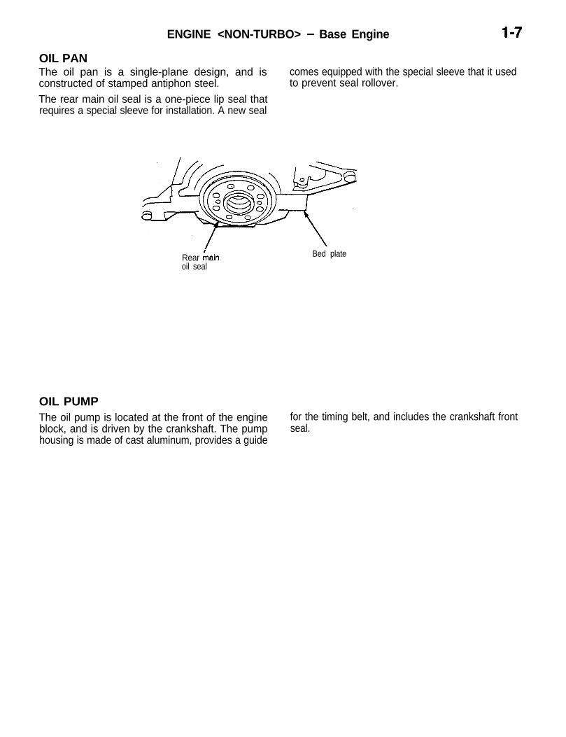
OIL PAN
LThe oil pan is a single-plane design, and isconstructed of stamped antiphon steel.The rear main oil seal is a one-piece lip seal thatrequires a special sleeve for installation. A new seal
comes equipped with the special sleeve that it usedto prevent seal rollover.
Rear hainoil seal
Bed plate
OIL PUMPThe oil pump is located at the front of the engineblock, and is driven by the crankshaft. The pumphousing is made of cast aluminum, provides a guide
for the timing belt, and includes the crankshaft frontseal.

I-8 ENGINE <NON-TURBO> - Cooling System
COOLING SYSTEMThe cooling system is of the water-cooled, forcedcirculation type with the following features:l The water pump is mounted onto the front of
the cylinder block, and is driven by the coggedside of the timing belt. The drive sprocket issintered metal. The pump body is made of diecast aluminum; and a stamped-steel impelleris used to pump coolant through the engine.
l The thermostat housing is located on the leftfront side of the engine. The thermostat ismounted under the thermostat housing, andthe center element is offset from the centerof its diameter. Therefore, it can only be installedone way. The thermostat has an air bleed (jigglepin) located in the flange, and an O-ring witha locating dimple. the bleed faces upward. Thethermostat temperature rating is 90.5%(195°F).
0
0
0
0
Coolant enters the water pump, where it isrouted through the engine block and into thecylinder head. Then, the coolant is routed fromcylinder head to both heater core and the radia-tor (engine hot) or through bypass (engine cold)to the water pump where the cycle starts overagain.A small-size, high-performance radiator hasbeen adopted for better cooling efficiency andless weight.Reduction in size of the automatic transaxleoil cooler had resulted in a lowered radiatorposition, which has permitted the “slant nose”design of the body.The cooling fan control has been integratedinto the centralized control by the engine controlmodule for better cooling efficiency, better fuelconsumption, less noise, and better accelera-tion.
COOLANT FLOW
8 1
Radiator [ r Water pump
Block q
ENGINE <NON-TURBO> - Cooling System
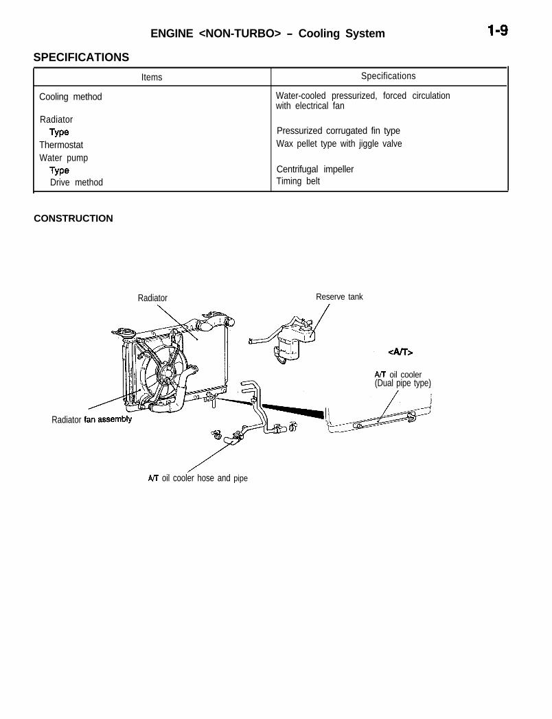
SPECIFICATIONS
Cooling method
RadiatorType
ThermostatWater pump
TypeDrive method
Items Specifications
Water-cooled pressurized, forced circulationwith electrical fan
Pressurized corrugated fin typeWax pellet type with jiggle valve
Centrifugal impellerTiming belt
CONSTRUCTION
Radiator Reserve tank
Radiator
NT oil cooler(Dual pipe type)
AtT oil cooler hose and pipe

I-10 ENGINE <NON-TURBO> - Intake and Exhaust
INTAKE AND EXHAUSTINTAKE MANIFOLD AND EXHAUST MANIFOLD i/i:The intake manifold is a two-piece aluminum casting, The exhaust manifold is made of nodular cast ironattached to the cylinder head with six bolts and for strength and high temperatures.two studs. This long branch fan design enhanceslow and midspeed torque. I
EXHAUST PIPEThe exhaust pipe consists of three parts: a front transmission from the exhaust system to the body.pipe, a center pipe, and a main muffler. It is mounted A large main muffler, sub muffler and pre-muff leron the body via rubber hangers to minimize vibration ensure reduced exhaust noise.
CONSTRUCTION
Flexible pipe
ted oxygen sensor
Pre-muff lerSub muffler
Heated oxygen sensor
Heated oxygen sensor
ENGINE <NON-TURBO> - Fuel System 1-11
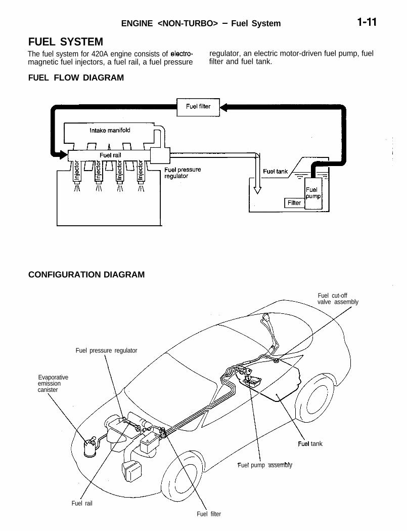
FUEL SYSTEMThe fuel system for 420A engine consists of electro-magnetic fuel injectors, a fuel rail, a fuel pressure
FUEL FLOW DIAGRAM
regulator, an electric motor-driven fuel pump, fuelfilter and fuel tank.
/I\ II\ II\
CONFIGURATION DIAGRAM
Fuel cut-offvalve assembly
Evaporativeemissioncanister
Fuel pressure regulator
\
Fuel pump assembly
Fuel tank
Fuel rail w\
Fuel filter

I-12 ENGINE <NON-TURBO> - Fuel System
FUEL TANKThe fuel tank is made of steel and is arranged underthe rear seat floor for higher safety. The fuel tankhas an internally mounted fuel pump assembly andfuel gauge unit. In addition, a fuel cut-off valve as-
sembly is standard equipment on all vehicles. Thefuel cut-off valve assembly prevents outflow of fueleven when the vehicle rolls over, assuring a highermeasure of safety.
Fuel

ENGINE <NON-TURBO> - Control System I-13
CONTROL SYSTEMGENERAL INFORMATIONThe fuel system for the 2.0 liter DOHC engine utilizessequential multi-port fuel injection to deliver preciseamounts of fuel to the intake manifold.Basic injector duration is controlled by a combinationof signals from the front oxygen sensor and an airdensity signal from a MAP sensor.This vehicle uses a direct ignition system, eliminatingthe need for a distributor. Ignition and fuel injector
operation are controlled by a new power-train controlmodule (PCM) which reviews inputs from a numberof sensors. The PCM provides outputs to fuel andignition system components to promote the mostefficient operation possible. The vehicle includesa catalytic converter and sophisticated emissionssystem diagnostic process (OBD II) to ensure thatemissions meet clean air regulations.
Major differences from the 1994 4G63 2.0 liter DOHC engine are as follows:
L
Major difference
Fast idle air valve is not equipped.
Remarks
On Mitsubishi manufactured engines, a fast idle air valveis equipped in the throttle body.
Closed throttle position switch is not equipped.
Speed adjusting screw is not equipped.
Fixed SAS is fixed at the production line.
Throttle position sensor is fixed to the throttle body atthe production line.
Basic idle speed is not adjustable.
Fixed SAS is not equipped.
Throttle position sensor is not adjustable.
Camshaft position sensor waveform is different from the A hall effect sensor is used, however, the construction ofcurrent one. the sensor is different.
Crankshaft position sensor waveform and its detection A same Hall effect sensor is used, however, themethod are different from those current ones. construction of the sensor is different.
On vehicles with automatic transaxle, vehicle speedsensor signal is input from TCM.
Ignition switch-ST (cranking) signal input is not pro- PCM judges as engine cranking when the engine speedvided . is low.
MFI relay (ASD relay) and fuel pump relay are separate- Currently, these two are combined into one relay.ly provided.
Generator generating voltage is controlled by PCM. Currently, it is controlled by the voltage regulator built inthe generator.
Tachometer is controlled by PCM.
Charging system indicator lamp is controlled by PCM.
Control of the indicator/warning lamps (just after turningON the ignition switch) is performed by PCM.
Pulsed secondary air injection is controlled by PCM.
Data transmission system between PCM and TCM isdifferent from the current one.
Battery temperature sensor is built in PCM.
PCM is mounted in the engine compartment.

ENGINE <NON-TURBO> - Control System
SYSTEM BLOCK DIAGRAM
Sensors
MAP Sensor
Engine coolant temperature sensor
Power-train control module (PCM) Actuators
-b Fuel injection control b No. 1 injector
---b No. 2 injectorb
b No. 3 injector
-bb No. 4 injector
Throttle position sensor - Idle air controlIdle air control motor(stepper motor)
Crankshaft position sensor + Ignition timing control -. Ignition coil
MFI relay control (Power supply) MFI relay (ASD relay)
IFuel pump control ,-b Fuel pump relay
I IAir conditioning compressorclutch relay control l-4
Air conditioning compressorclutch relay I
Fan relay controlRadiator fan motor relay and air
IGenerator generating voltagecontrol Generator
Power steering pressure switch
Park/Neutral position switch <A/T>
Ignition switch-IG (J2 SENSE)
bTachometer control
---b Charging system indicator lampcontrol
Tachometer
Charging system indicator lamp
Check engine/mal funct ion,indicator lamp control
Knock sensor -b Control of indicator/warninglamps in the instrument panel
Break switch + Diagnostic output
Power supply + RAM data transmission
MFI relay operating voltage(ASD SENSE)
I
EGR controlb
Indicator/warning lamps in the
E Diagnostic output terminali
Diagnostic output terminal (MUT)
I II-I EVAP purge solenoid I
I - - + ( EGR solenoid I
1 ’Pulsed secondary air injectioncontrol i I
.-b Pulsed secondary air injection
4
t/ Battery temperature sensor 1 1
solenoid
’

ENGINE <NON-TURBO> - Control System I-15
MULTIPORT FUEL INJECTION (MFI) SYSTEM DIAGRAM
*l Heated oxygen sensor (Front)*2 Manifold absolute pressure sensor*3 intake air temperature sensor~4 Throttle position sensor+5 Camshaft position sensor*6 Crankshaft position sensor*7 Engine coolant temperature sensor~8 Knock sensor*9 Heated oxygen sensor (Rear)l Power supplyl Vehicle speed sensorl A/C switchl Park/Neutral position switchl Power steering pressure switchl Ignition switch-IG (J2 sense)l Brake switchl MFI relay (ASD relay)
al injectora2 Evaporative emission purge solenoida3 Idle air control motora4 EET solenoida5 Ignition coilti Pulsed secondary air injection solenoidl Fuel pump relay0 Multiport fuel injection (MFI) relay
(ASD relay)l Air conditioning compressor clutch relayl Check engine/Malfunction indicator lampl Diagnostic outputl Fan motor relayl Generatorl Engine speed meterl Changing warning lightl Indicator/warning lamps in the instrument
panel
c3 Powertrain control timodule (PCM)
I I
Evaporative emissionpurge solenoid
Throttle oosition
valve
. . ..etAir inl
II, transducer solenoid - - -
,, ,,r $$kS @-i!$ion ’
From fuel pump - -
Engine
Air cleaner
Manifold absolutepressure sensor *2
Intake air temperature sensor *3
A5 Camshaft position sensor 1
Heated oxygensensor (Front) I I I
[email protected] 1arr mjectronsolenoid I
II
MTToniy I
coolant temperature sensor *7
Knock sensorCrankshaft position sensor A6
s~y+a.vw;ectron He:ted oxygen
Sensor (rear)

ENGINE <NON-TURBO> - Control Svstem
SENSORSMANIFOLD ABSOLUTE PRESSURE (MAP) SENSORThe powertrain control module (PCM) supplies 5volts direct current to the MAP sensor. The MAP
mospheric air pressure from the MAP sensor volt-
sensor converts intake manifold pressure into volt-age. While the engine operates, the PCM deter-
age. The PCM monitors the MAP sensor outputmines intake manifold pressure from the MAP sen-
voltage. As vacuum increases, MAP sensor voltagesor voltage. Based on MAP sensor voltage and
decreases proportionately. Also, as vacuum de-inputs from other sensors, the PCM adjusts sparkadvance and the air/fuel mixture.
creases, MAP sensor voltage increases proportion-ately.At wide-open-throttle and during cranking, beforethe engine starts running, the PCM determines at-
The MAP sensor mounts to the intake manifold.
INTAKE AIR TEMPERATURE SENSORThe intake air temperature sensor measures thetemperature of the air as it enters the engine. Thesensor supplies one of the inputs the PCM usesto determine injector pulse width and spark advance.
The intake air temperature sensor threads into theintake manifold.
= Intake _ - -- - -. ---.---- Intake air
ENGINE <NON-TURBO> - Control System 1-17
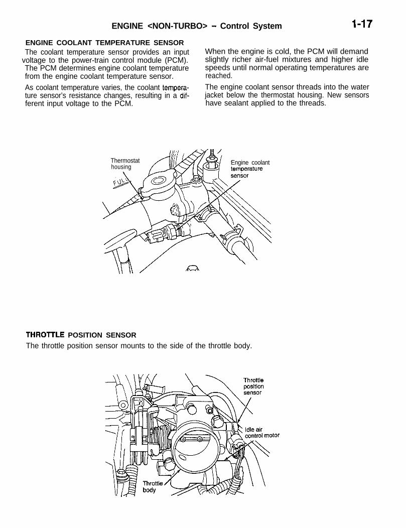
ENGINE COOLANT TEMPERATURE SENSORThe coolant temperature sensor provides an input
voltage to the power-train control module (PCM).The PCM determines engine coolant temperaturefrom the engine coolant temperature sensor.As coolant temperature varies, the coolant tempera-ture sensor’s resistance changes, resulting in a dif-ferent input voltage to the PCM.
When the engine is cold, the PCM will demandslightly richer air-fuel mixtures and higher idlespeeds until normal operating temperatures arereached.The engine coolant sensor threads into the waterjacket below the thermostat housing. New sensorshave sealant applied to the threads.
Thermostathousing
\Engine coolanttemperature
\
THROlTLE POSITION SENSOR
The throttle position sensor mounts to the side of the throttle body.

l-18 ENGINE <NON-TURBO> - Control System
The throttle position sensor (TPS) connects to thethrottle blade shaft. The TPS is a variable resistorthat provides the powertrain control module (PCM)with an input signal (voltage). The signal representsthrottle blade position. As the position of the throttleblade changes, the resistance of the TPS changes.The PCM supplies approximately 5 volts to the TPS.The TPS output voltage (input signal to the power-train control module) represents throttle blade posi-
CAMSHAFT POSITION SENSORThe PCM determines ignition and fuel injection syn-chronization and cylinder identification from inputsprovided by the camshaft position sensor and crank-
tion. The TPS output voltage to the PCM variesfrom approximately 0.40 volt at minimum throttleopening (idle) to a maximum of 3.80 volts at wideopen throttle.Along with inputs from other sensors, the PCM usesthe TPS input to determine current engine operatingconditions. The PCM also adjusts fuel injector pulsewidth and ignition timing based on these inputs.
shaft position sensor. From the two inputs, the PCMdetermines crankshaft position and cylinder cycle.
’ Camshaft
- .y $gd$ heat

ENGINE <NON-TURBO> - Control System 1-19
The camshaft position sensor attaches to the rear
L
of the cylinder head. A target magnet attaches tothe rear of the camshaft and indexes to the correctposition. The target magnet has four different polesarranged in an asymmetrical pattern. As the targetmagnet rotates, the camshaft position sensorsenses the change in polarity. The sensor output
switch switches from high (5.0 volts) to low (0.30volts) as the target magnet rotates. When the northpole of the target magnet passes under the sensor,the output switches high. The sensor output switcheslow when the south pole of the target magnet passesunderneath.
Rear off3Ainder /A
7 m
/ The camshaft position sensor is mounted to therear of the cylinder head. The sensor also acts as
CRANKSHAFT POSITION SENSORThe PCM determines what ignition coil to energizefrom the crankshaft position sensor input and thecamshaft position sensor input. The second crank-shaft counterweight has machined into it two sets
Targetmagnet
a thrust plate to control camshaft endplay.
of four timing reference notches and a 60 degreesignature notch. From the crankshaft position sensorinput the PCM determines engine speed and crank-shaft angle (position).
Crankshaft 1positionsensor

l-20 ENGINE <NON-TURBO> - Control System
The notches generate pulses from high to low inthe crankshaft position sensor output voltage. Whena metal portion of the counterweight aligns withthe crankshaft position sensor, the sensor outputvoltage goes low (less than 0.3 volts). When a notchaligns with the sensor, voltage spikes high (5.0 volts).As a group of notches pass under the sensor, theoutput voltage switches from low (metal) to high(notch) then back to low.If available, an oscilloscope can display the squarewave patterns of each voltage pulse. From the widthof the output voltage pulses, the PCM calculatesengine speed. The width of the pulses representthe amount of time the output voltage stays highbefore switching back to low. The period of timethe sensor output voltage stays high before switch-ing back to low is referred to as pulse width. Thefaster the engine is operating, the smaller the pulsewidth on the oscilloscope.
lates crankshaft angle (position). In each group oftiming reference notches, the first notch represents69 degrees before top dead center (BTDC). Thesecond notch represents 49 degrees BTDC. Thethird notch represents 29 degrees. The last notchin each set represents 9 degrees before top deadcenter (TDC).The timing reference notches are machined to auniform width representing 13.6 degrees of crank-shaft rotation. From the voltage pulse width the PCMtells the difference between the timing referencenotches and the 60 degree signature notch. The60 degree signature notch produces a longer pulsewidth than the smaller timing reference notches.If the camshaft position sensor input switches fromhigh to low when the 60 degree signature notchpasses under the crankshaft position sensor, thePCM knows cylinder number one is the next cylinderat TDC.
By counting the pulses and referencing the pulsefrom the 60 degree signature notch, the PMC calcu-
2 1 0 ” I 150” piiq 2 1 0 ”1 I
T D C TDC TDC TDC69” 49”29” 9”l 3
Cranksignal + + I
Crank 360 400 440 480 520 560 600 640 600 720
angle 00 4 0 8 0 1 2 0 1 6 0 2 0 0 2 4 0 2 8 0 3 2 0 0 4 0 8 0 1 2 0 1 6 0 2 0 0 2 4 0 2 8 0 3 2 0 0

ENGINE <NON-TURBO> - Control System I-21
The crankshaft position sensor mounts to the engine block behind the generator, just above the oil filter.
HEATED OXYGEN SENSORS
As vehicles accumulate mileage, the catalytic con-vertor deteriorates. The deterioration results in aless efficient catalyst. To monitor catalytic convertordeterioration, the fuel injection system uses twoheated oxygen sensors. One sensor upstream ofthe catalytic convertor, one downstream of the con-vertor. The powertrain control module (PCM)compares the reading from the sensors to calculatethe catalytic convertor oxygen storage capacity andefficiency. Also, the PCM uses the upstream heatedoxygen sensor input when adjusting injector pulsewidth.
When a deteriorating catalyst’s efficiency drops be-low emission standards, the PCM stores a diagnostictrouble code and illuminates the malfunction indica-tor lamp (MIL).The MFI relay (automatic shut down relay) suppliesbattery voltage to both the upstream and down-stream heated oxygen sensors. The oxygen sensorsare equipped with a heating element. The heatingelement keeps the sensors at proper operating tem-perature during all operating modes.

I-22 ENGINE <NON-TURBO> - Control System
-UpstreamThe input from the upstream heated oxygen sensortells the PCM the oxygen content of the exhaustgas. Based on this input, the PCM fine tunes theair-fuel ratio by adjusting injector pulse width.The sensor produces from 0 to 1 volt, dependingupon the oxygen content of the exhaust gas in theexhaust manifold. When a large amount of oxygenis present (caused by a lean air-fuel mixture), thesensor produces voltage as low as 0.1 volt. Whenthere is a lesser amount of oxygen present (richair-fuel mixture) the sensor produces a voltage ashigh as 1.0 volt. By monitoring the oxygen contentand converting it to electrical voltage, the sensoracts as a rich-lean switch.The heating element in the sensor maintains correctoxygen sensor temperature. Maintaining correct
sensor temperature at all times allows the systemto enter into Closed Loop operation sooner. Also,it allows the system to remain in Closed Loop opera-tion during periods extended’ idle.In Closed Loop operation the PCM monitors theinputs from the heated oxygen sensors (along withother inputs). In Closed Loop, the PCM adjusts injec-tor pulse width based on the upstream heated oxy-gen sensor input. During Open Loop operation thePCM ignores the inputs from both the upstreamand downstream heated oxygen sensors. In OpenLoop, the PCM adjusts injector pulse width basedon preprogrammed (fixed) values and inputs fromother sensors.The upstream oxygen sensor threads into the outletflange of the exhaust manifold.
DownstreamThe downstream heated oxygen sensor threadsinto the exhaust pipe at the rear of the catalyticconvertor. The downstream heated oxygen sensorinput is used to detect catalytic convertor deteriora-tion. As the convertor deteriorates, the input from
the downstream sensor begins to match the up-stream sensor input except for a slight time delay.By comparing the downstream heated oxygen sen-sor input to the input from the upstream sensor,the PCM calculates catalytic convertor efficiency.
_ Downstream heated= oxygen sensor2
convertor
ENGINE <NON-TURBO> - Control System I-23
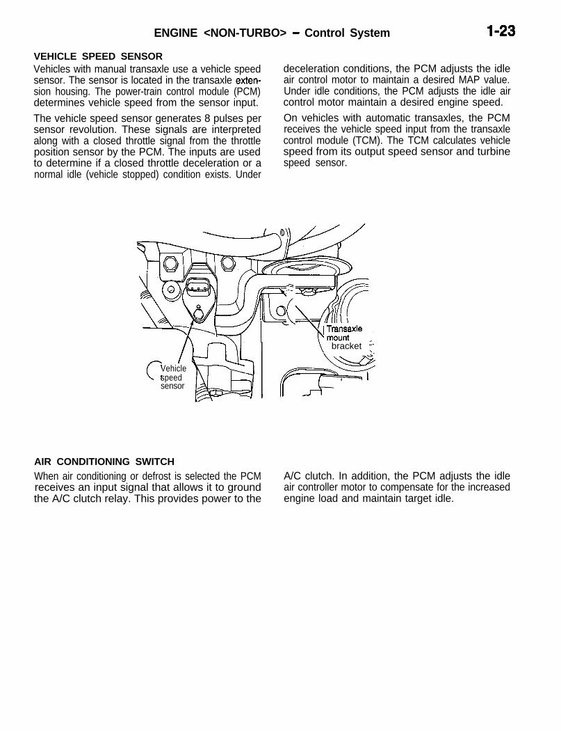
VEHICLE SPEED SENSOR
i
Vehicles with manual transaxle use a vehicle speed deceleration conditions, the PCM adjusts the idlesensor. The sensor is located in the transaxle exten- air control motor to maintain a desired MAP value.sion housing. The power-train control module (PCM) Under idle conditions, the PCM adjusts the idle airdetermines vehicle speed from the sensor input. control motor maintain a desired engine speed.The vehicle speed sensor generates 8 pulses per On vehicles with automatic transaxles, the PCMsensor revolution. These signals are interpreted receives the vehicle speed input from the transaxlealong with a closed throttle signal from the throttle control module (TCM). The TCM calculates vehicleposition sensor by the PCM. The inputs are used speed from its output speed sensor and turbineto determine if a closed throttle deceleration or a speed sensor.normal idle (vehicle stopped) condition exists. Under
w
iF
’ w/l’d
/1° \TIzi// AllkJ~,qf((- I “---7xle
\ bracket F
c IVehiclespeedsensor
AIR CONDITIONING SWITCH
When air conditioning or defrost is selected the PCMreceives an input signal that allows it to groundthe A/C clutch relay. This provides power to the
A/C clutch. In addition, the PCM adjusts the idleair controller motor to compensate for the increasedengine load and maintain target idle.

I-24 ENGINE <NON-TURBO> - Control System
POWER STEERING PRESSURE SWITCHA pressure switch is located on the power steeringunit’s body to signal periods of high pump load andpressure, such as those which occur during parkingmaneuvers. This allows the PCM to maintain target
PARK/NEUTRAL SWITCHThe park/neutral switch is located on the automatictransxale housing. Manual transaxles do not usepark neutral switches. The switch provides an inputto the PCM. The input indicates whether the auto-matic transaxle is in Park, Neutral, or a drive gear
idle speed. To compensate for the additional engineload, the PCM increases airflow by adjusting the idle air control motor.
selection. This input is used to determine idle speed(varying with gear selection), fuel injector pulsewidth, and ignition timing advance. The park neutralswitch is sometimes referred to as the neutral safetyswitch.
F/f~/~: am , , 0~;~;; speed
.““.I ..
{itch
IGNITION SWITCH-IG (J2 SENSE)
The ignition sense input informs the power-train con-trol module (PCM) that the ignition switch is in theCrank or Run position.
ENGINE <NON-TURBO> - Control System I-25
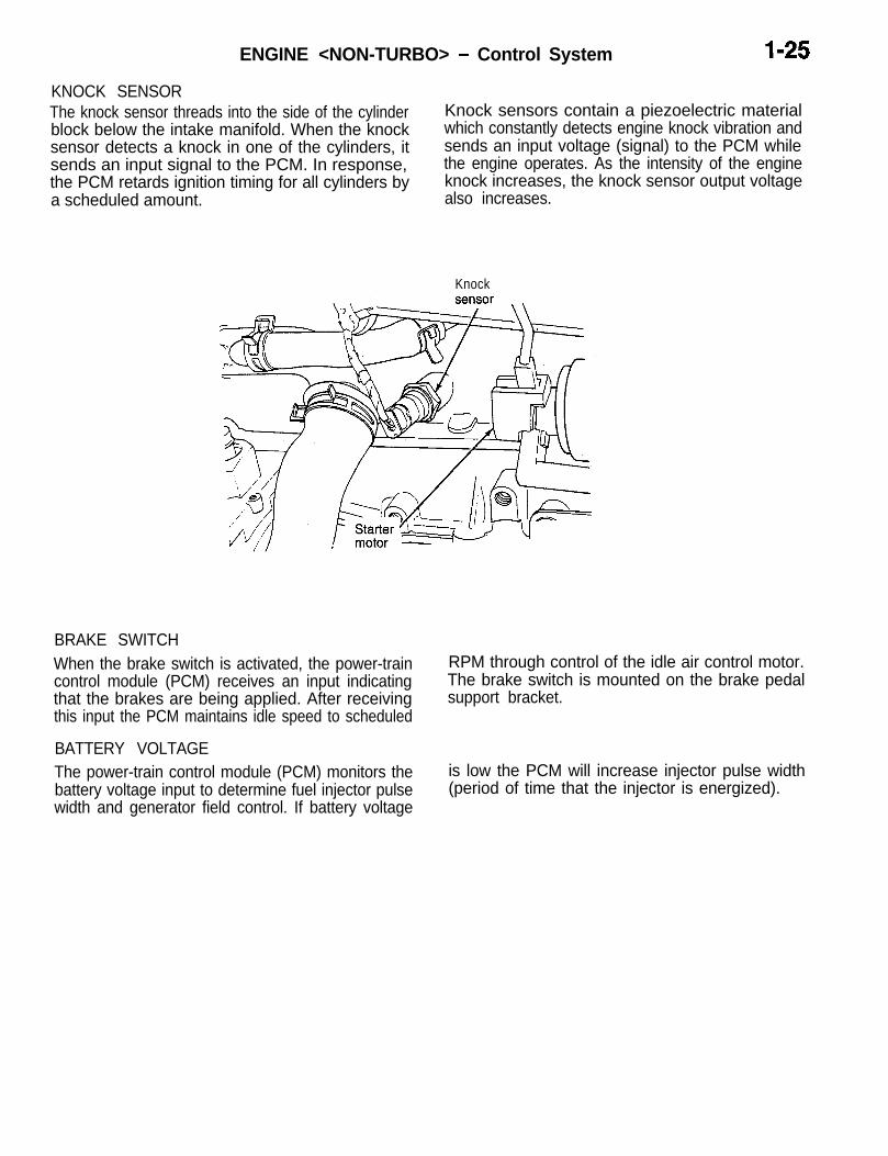
KNOCK SENSORThe knock sensor threads into the side of the cylinder Knock sensors contain a piezoelectric materialblock below the intake manifold. When the knock which constantly detects engine knock vibration andsensor detects a knock in one of the cylinders, it sends an input voltage (signal) to the PCM whilesends an input signal to the PCM. In response, the engine operates. As the intensity of the enginethe PCM retards ignition timing for all cylinders by knock increases, the knock sensor output voltagea scheduled amount. also increases.
Knock
BRAKE SWITCHWhen the brake switch is activated, the power-traincontrol module (PCM) receives an input indicatingthat the brakes are being applied. After receivingthis input the PCM maintains idle speed to scheduled
RPM through control of the idle air control motor.The brake switch is mounted on the brake pedalsupport bracket.
BATTERY VOLTAGEThe power-train control module (PCM) monitors thebattery voltage input to determine fuel injector pulsewidth and generator field control. If battery voltage
is low the PCM will increase injector pulse width(period of time that the injector is energized).

1-26 ENGINE <NON-TURBO> - Control System
ACTUATORS AND CONTROLFUEL INJECTORSThe 2.0L engine uses electrically operated top feedfuel injectors. The MFI relay (automatic shut downrelay) supplies battery voltage to the fuel injectors.The PCM controls the ground path for each injectorin sequence. By switching the ground paths on andoff, the PCM fine-tunes injector pulse width. Injectorpulse width refers to the amount of time an injectoroperates.The PCM determines injector synchronization fromthe camshaft position sensor and crankshaft position
IDLE AIR CONTROL MOTORThe idle air control (IAC) motor is mounted on thethrottle body. The PCM operates the idle air controlmotor. The PCM adjusts engine idle speed throughthe idle air control motor to compensate for engineload or ambient conditions.The throttle body has an air bypass passage thatprovides air for the engine during closed throttleidle. The idle air control motor pintle protrudes intothe air bypass passage and regulates air flowthrough it.
sensor inputs. The PCM grounds the MFI and fuelpump relays after receiving the camshaft positionsensor and crankshaft position sensor inputs.The PCM energizes the injectors in a sequentialorder during all engine operating conditions exceptstart-up. For the first injector pulse width duringstart-up, all injectors are energized at the sametime. Once the PCM determines crankshaft position,it beings energizing the injectors in sequence.
The PCM adjusts engine idle speed by moving theIAC motor pintle in and out of the bypass passage.The adjustments are based on inputs the PCM re-ceives. The inputs include the throttle position sen-sor, crankshaft position sensor, coolant temperaturesensor, vehicle speed sensor and various switchoperations (brake, park/neutral, air conditioning,power steering).

ENGINE <NON-TURBO> - Control Svstem I-27
IGNITION COIL
L
The coil assembly consists of 2 coils molded togeth-er. The coil assembly is mounted on the cylinderhead cover. High tension leads route to each cylinderfrom the coil. The coil fires two spark plugs everypower stroke. One plug is the cylinder under com-pression, the other cylinder fires on the exhauststroke. Coil number one fires cylinders 1 and 4.Coil number two fires cylinders 2 and 3. The power-train control module (PCM) determines which ofthe coils to charge and fire at the correct time.
The MFI relay (automatic shut down relay) providesbattery voltage to the ignition coil. The PCM providesa ground contact (circuit) for energizing the coil.When the PCM breaks the contact, the energy inthe coil primary transfers to the secondary causingthe spark. The PCM will de-energize the MFI relayif it does not receive the crankshaft position sensorand camshaft position sensor inputs. Refer to MFIRelay PCM Output in this section for relay operation.
MFI RELAY (Automatic Shut Down)The MFI relay (automatic shut down relay) suppliesbattery voltage to the fuel injectors, electronic igni-tion coil, generator, and the heating elements inthe oxygen sensors.The PCM controls the relay by switching the groundpath for the solenoid side of the relay on and off.The PCM turns the ground path off when the ignitionswitch is in the Off position. When the ignition switchis in the On or Crank position, the PCM monitors
the crankshaft position sensor and camshaft positionsensor signals to determine engine speed and igni-tion timing (coil dwell). If the PCM does not receivethe crankshaft position sensor and camshaft positionsensor signals when the ignition switch is in theRun position, it will de-energize the MFI relay.Along with the fuel pump relay, the MFI relay at-taches to a bracket on the drivers side of the dashpanel.
\ e Fuel Dump
MFI relay 1 0
Struttower
I

ENGINE <NON-TURBO> - Control System
FUEL PUMP RELAY
The fuel pump relay supplies battery voltage to thefuel pump. The PCM controls the fuel pump relayby switching the ground path for the solenoid sideof the relay on and off. The PCM turns the groundpath off when the ignition switch is in the Off position.When the ignition switch is in the On position, thePCM energizes the fuel pump. If the crankshaft
position sensor does not detect engine rotation,the PCM de-energizes the relay after’approximatelyone second.Along with the MFI relay, the fuel pump relay at-taches to a bracket on the drivers side of the dashpanel.
AIR CONDITIONING CLUTCH RELAY
The PCM provides the ground path for the relaycoil. Relay operation is based on inputs the PCMreceives from the air conditioning switch. The PCMdeactivates the relay at vehicle start-up and also
if it senses a part throttle/wide open throttle launchcondition. This temporarily reduces the accessoryload on the engine.
RADIATOR FAN RELAY AND AIR CONDlTIONING CONDENSER FAN RELAY (High, LOW)
The PCM operates the relay based on inputs from The PCM supplies the ground circuit for the High/the engine coolant temperature sensor, vehicle Low relay coil to operate the fan motor in high/lowspeed sensor and A/C system. speeds.
CHARGING SYSTEM INDICATOR LAMP
The PCM controls operation of the charging systemindicator lamp located in the vehicle’s instrumentcluster. The PCM provides a ground to completethe lamp circuit if the charging output falls belowa specified threshold.
The PCM also supplies the ground circuit for thelamp circuit for 3 seconds after the ignition switchis turned to the ON position and illuminates theindicator lamp.
TACHOMETER
The PCM operates the tachometer on the instrumentpanel. The PCM calculates engine RPM from the
crankshaft position sensor input.
GENERATOR
The PCM controls the generator field current toregulate the generator output voltage to the target
voltages in accordance with the battery tempera-tures.

ENGINE <NON-TURBO> - Control System 1-29
DUTY CYCLE EVAP PURGE SOLENOID
i
The duty cycle EVAP purge solenoid regulates therate of vapor flow from the EVAP canister to thethrottle body. The power-train control module oper-ates the solenoid.During the cold start warm-up period and the hotstart time delay, the PCM does not energize thesolenoid. When de-energized, no vapors are purged.The PCM de-energizes the solenoid during OpenLoop operation.The engine enters Closed Loop operation after itreaches a specified temperature and the pro-
grammed time delay ends. During Closed Loop op-eration, the PCM energizes and de-energizes thesolenoid 5 to 10 times per second, depending uponoperating conditions. The PCM varies the vaporflow rate by changing solenoid pulse width. Pulsewidth is the amount of time the solenoid is de-ener-gized.The solenoid attaches to a bracket next to the EVAPcanister. The canister is located ahead of the pas-senger’s front wheel well.

I-30 ENGINE <NON-TURBO> - Control System
ELECTRIC EGR TRANSDUCERThe Electronic EGR Transducer (EET) contains anelectrically operated solenoid and a back-pressurecontrolled vacuum transducer. The PCM operatesthe solenoid based on inputs from the multi-portfuel injection system. The EET and EGR valve areserviced as an assembly.When the PCM de-energizes the solenoid, vacuumdoes not reach the transducer. Vacuum flows tothe transducer when the PCM energizes the sole-noid.When exhaust system back-pressure becomes highenough, it fully closes a bleed valve in the vacuumtransducer. When the PCM energizes the solenoid
and back-pressure closes the transducer bleedvalve, vacuum flows through the transducer to oper-ate the EGR valve. d
Energizing the solenoid, but not fully closing thetransducer bleed hole (because of low back-pres-sure), varies the strength of the vacuum signal ap-plied to the EGR valve. Varying the strength of thevacuum signal changes the amount of EGR suppliedto the engine. This provides the correct amountof exhaust gas recirculation for different operatingconditions.The EET and EGR valve mount to the rear of thecylinder head.

ENGINE <NON-TURBO> - Control Svstem 1-31
DIAGNOSTIC SYSTEM
idMALFUNCTION INDICATOR LAMP (MIL)The PCM provides the ground path for the malfunc-tion indicator lamp (Check Engine light in the gaugecluster on the instrument panel). The lamp comeson each time the ignition key is turned ON andstays on for a 3 seconds bulb test.The MIL lamp stays on continuously, when the PCMhas entered a Limp-in mode or identified a failedemission component. During Limp-in Mode, thePCM attempts to keep the system operational. Themalfunction indicator lamp signals the need for im-mediate service. In limp-in mode, the PCM compen-sates for the failure of certain components that sendincorrect signals by substituting inputs from othersensors.
GENERAL INFORMATIONThe diagnostic system for vehicles with a manualtransaxle conforms to OBD-II, where the one forvehicles with an automatic transaxle conforms toOBD-I.OBD II has been developed to allow to meet therequirements of the Federal Clean Air Act andCalifornia Air Resources Board (CARB) legislation.It is impractical (and very expensive) to provideevery vehicle on the road with the equipment neces-sary to measure emissions of carbon monoxide(CO), hydrocarbons (HC) and oxides of nitrogen(NOx). Instead, the proven emissions control de-vices available for these vehicles are checked forproper operation.
MIL ILLUMINATION:
If the PCM detects active engine misfire severeenough to cause catalyst damage, it flashes themalfunction indicator lamp (Check Engine light). ,Atthe same time the PCM also sets a diagnostic troublecode. <vehicles with manual transaxle>The malfunction indicator lamp can also displaydiagnostic trouble codes. Cycle the ignition switchon, off, on, off, on, within five seconds and the PCMdisplays any diagnostic trouble codes stored inmemory.The diagnostic trouble codes can also be read bythe scan tool.
NOTEWhen monitoring the misfire and fuel system, iftrouble is detected, the MIL will light until the comple-tion of the next operation cycle (trip) following thecycle where the trouble is detected. In addition,if the detected trouble may cause damage to thecatalytic converter, the MIL will light immediately.However, if the trouble is not detected in thesucceeding trip under almost the same driving condi-tion, MIL should go out. And if the same troublewill not be detected within 80 trips following thetrip where the trouble is detected, the diagnostictrouble code will be erased.
. FAULT ON TWO SUCCESSIVE TRIPS -
. (MIL ON) NO FAULT ON THREESUCCESSIVE TRIPS b
MIL ON
MIL OFF
FAULT CODE STORAGE:. FAULT ON TWO SUCCESSIVE TRIPS h
. (DTC) NO FAULT ON 40-80SUCCESSIVE TRIPS b
DIAGNOSTIC TROUBLECODE STOREDDIAGNOSTIC TROUBLECODE ERASED

1-32 ENGINE <NON-TURBO> - Control System
In addition to illuminating the MIL lamp, a diagnostictrouble code (DTC) is stored in the Powertrain Con-trol Module (PCM) and can be retrieved by a servicetechnician using a diagnostic scan tool.To meet OBD-II requirements the following systemsmust be monitored:0 Catalystl Fuel Systeml Misfirel Oxygen Sensor and Oxygen Sensor Heaterl Secondary Airl Evaporative System (Purge)l Exhaust Gas Recirculationl Any other input or output component that can
affect emissionsThe operating conditions of the components canbe monitored using MUT-II scan tool, as well asgeneral purpose scan tools. The OBD II systemmonitors are different. They are checks made by
DIAGNOSTIC SYSTEM OPERATION
Trip Indicator
“Trip” is a difficult concept to define because therequirements for a trip vary depending on the testbeing run. These conditions can include seeminglyunrelated items such as driving style, length of trip,and ambient temperature. The minimum require-ment for a trip is that it includes one key cycle withthe vehicle having to meet certain enabling condi-tions before a test is performed. Vehicle tests varyin length and may be performed only once per tripor may be performed continuously. If the pertinentenabling conditions are not met during that key cycle,the tests may not run at all.NOTEIn California and other states requiring the PCMto indicate that all monitors have passed beforeissuing license plates, removing the vehicle’s batteryor using the MUT-II scan tool to erase DTC’s beforetesting erases any record of passing a monitor. Ifthe monitor does not complete a trip on subsequentkey cycles, the vehicle will fail a licensing test.What constitutes a trip for a particular OBD testis important because in many instances, the vehiclemust fail a test on more than once before the MILis illuminated and a DTC is recorded. Tests thatilluminate the MIL when a single failure is recordedare known as “one trip” monitors. “Two trip” monitors
the PCM’s software to determine not only if thesespecific systems are operating, but if they are operat-ing within pre-established limits. While OBD I testsmeasure a component’s electrical operation, OBDII monitors check a system’s performance.The California Air Resources Board (CARB) moni-tors emission system repairs from several Californiadealers. If a specific component or system fails onmore than 4% of the vehicles sampled, the manufac-turer is required to research and evaluate the rea-sons. If the failure is not attributable to owner negli-gence or misuse, a component failure rate of 4%could lead to vehicle recalls. The federal governmentis considering a similar program. The manufactureris relying on its technicians throughout the countryto appropriately diagnose emissions concerns andreplace only those parts that have failed. The sloppypractice of “hanging” parts on a car under emissionswarranty could lead to an unnecessary (and expen-sive) fleet-wide recall.
allow the system to double check itself and helpprevent unnecessary MIL illumination.If the conditions to run the test are not met on consec-utive key cycles, the information from the first test ’is not lost. The diagnostic system waits until thenext time the appropriate test conditions occur andcontinues the count.If this is a “two trip fault” and the test failed thefirst time, a malfunction the second consecutivetime the test is run (even if there were ten keycycles between these tests) will illuminate the MIL.If the malfunction does not occur the second timethe test is run, the MIL lamp does not illuminateand no DTC is recorded.The diagnostic system can turn the MIL off if it re-cords three consecutive trips where the systempasses the test. However, with the misfire and fuelmonitors, the system must past the test under thesame circumstances (within 375 rpm) under whichit failed the test.In summary, it is the diagnostic system’s job to deter-mine if the conditions are appropriate for a testto be run, know the definition of a trip for eachtest, and record the results of each test when itis run.

ENGINE <NON-TURBO> - Control System 1-33
DTC Identification, Maturation, and Erasure
Once a test has been run, the diagnostic systemdetermines whether the system has passed or failed.It must then determine if the test has failed thespecified number of times required to illuminate theMIL. If not, the diagnostic system stores a maturingcode. When this test is run again (on the next “trip”)the results are once again either pass or fail. Ifthe component fails the test, a code “matures,” anda DTC is set. The MIL lamp is illuminated if anemission component is involved. If the componentor system passes the test a specified number oftimes, the maturing code is erased.NOTEIt is important to understand that a system neednot fail a test under exactly the same conditionsfor a code to nature and trigger the MIL.
Freeze Frame Data Storage and Erasure
All monitored systems provide “freeze frame” dataof the vehicle’s operating conditions when a matur-ing code was set. This information can be retrievedusing the diagnostic scan tool and may help a techni-cal pinpoint the source of a concern more quickly.When there are multiple monitor failures, the firstto occur is stored in freeze frame. The exceptions
Lare the misfire and fuel system monitors. They have
priority and can write over other freeze frame data.
Freeze Frame Priority
The freeze frame only indicates the operating condi-tions under which the maturing code was set. Whilethese conditions are usually the same as thosewhich trigger the maturation of the DTC, there canbe exceptions. This first condition is important forfuel system and misfire DTC’s as it is the condition
MIL Illumination
As described earlier, the PCM diagnostic systemis responsible for operation of the MIL lamp. Thisis an important function as unnecessary operationof this lamp has a negative effect on customer satis-faction. In most cases, if a component or systempasses diagnostics on three consecutive trips afterthe MIL has been illuminated, the MIL is extin-guished. This explains how customers can notethat the “Check Engine” light went on, and thenoff, on its own. The OBD II has reconsidered itsdiagnosis. The DTC remains in the memory until
DTC’s are erased if the component passes the diag-nostic test in the course of a number of subsequentwarm-up cycles. The number of trips required forthis is usually 40. This is why it is best to attemptto diagnose intermittent problems soon after theyoccur. While initially a DTC may have been available,subsequent trips (which passed the diagnostic test)have erased the code. The OBD II system, basedon the latest inputs it received, reconsidered itsdiagnosis on this intermittent concern.Of course, a diagnostic scan tool can be used toerase DTC’s at any time. In addition, DTC’s (alongwith records of successful trips) are erased whenev-er the vehicle’s battery is disconnected.
Information in the freeze frame includes:l Diagnostic Trouble Code (DTC)l Engine rpml Engine loadl Fuel trim (short term and long term)o Engine coolant temperaturel Manifold absolute pressurel Operation mode (open or closed loop)l Vehicle speed
the vehicle must repeat successfully during a testto allow the diagnostic system to erase a DTC andturn off the MIL on its own.Should the diagnostic system determine that theDTC can be erased, the freeze frame related tothat code is also eliminated.
a larger number of warm-up cycles (40) have beensuccessfully completed.The MIL flashed in misfire situations where contin-ued driving could damage the catalytic converter.Continued driving of the vehicle when this conditionoccurs is not recommended.The MIL can be used to produce diagnostic troublecodes. Quickly turning the key to the RUN positionthree times allows the MIL to flash out any existingflash codes.

I-34 ENGINE <NON-TURBO> - Control System
Test condition
There are a large number of tests waiting to beperformed once the vehicle is stat-ted. It is the diag-nostic system’s job to see that these tests are notonly performed, but performed under the appropriateconditions.An additional job of the diagnostic system is to pre-vent false DTC’s from being stored. The diagnosticsystem accomplishes this by not running certaintests when it recognizes that faults already in thesystem or tests currently being run could causethe next test to fail erroneously. For example:
The test for the catalyst monitor does not runif the MIL light is on due to an oxygen sensorfault. The oxygen sensor is a key componentin the catalyst monitor test. If the sensor is notfunctioning properly, there is no reason to runthe catalyst monitor - it won’t pass. This testwill not be run pending repair of the sensorconcern.
The diagnostic system does not run the testmonitoring catalyst operation if the EGR monitor test is being run. The EGR monitor is an “intru-sive” test and will cause the catalyst monitorto produce data not representative of normaloperating conditions. This represents a conflictof test data. The diagnostic system will waituntil the EGR monitor is finished before runningthe catalyst monitor.Finally, the results from the catalyst monitorare always held until the oxygen sensor testhas been successfully completed. The resultsfrom the test are suspended until the requiredprerequisite test has been completed.
By reviewing these guidelines, the diagnostic systemavoids storing DTC’s that are the result of failureof other components in the system. The diagnosticsystem allows you to use the diagnostic scan toolmore confidently in diagnosing and repairing a con-cern.
DIAGNOSTIC TROUBLE CODES
The diagnostic items are shown in the following table. Note that a fault’s numeric codes are different,depending on the method of inspection.
Diagnostic trouble code No.
Scan tool General scan Diagnostic items(MUT-II) tool MIL
01 PO340 54 No cam signal at PCM
02 PO605 53 Internal controller failure
05 47 Charging system voltage too low
06 46 Charging system voltage too high
10 42 MFI relay (ASD relay) control circuit
11 41 Generator field not switching properly
16 - 33 A/C clutch relay circuit
17 PO403 32 EGR solenoid circuit
18 PO443 31 EVAP solenoid circuit
19 PO203 27 Injector #3 control circuit
20 PO202 27 Injector #2 control circuit
21 PO201 27 Injector #l control circuit
25 PO505 25 Idle air control motor circuits
26 PO122 24 Throttle position sensor voltage low
MIL: Check engine/Malfunction indicator lamp

ENGINE <NON-TURBO> - Control System
Diagnostic trouble code No.
Scan tool General scan Diagnostic items(MUT-II) tool MIL
27 PO123 24 Throttle position sensor voltage high
30 PO117 22 Engine coolant temperature sensor voltage too low
31 PO118 22 Engine coolant temperature sensor voltage too high
32 PO134 21 Upstream H02S stays at center
33 17 Engine is cold too long
35 PO500 15 No vehicle speed sensor signal
36 PO1 07 14 MAP sensor voltage too low
37 PO1 08 14 MAP sensor voltage too high
39 P1297 13 No change in MAP from start to run
40 PO335 11 No crank reference signal at PCM
42 PO352 43 Ignition coil #2 primary circuit
43 PO351 43 Ignition coil #l primary circuit
44 42 No MFI relay (ASD relay) output voltage at PCM
46 PO401 32 EGR system failure
48 62 PCM failure SRI mile not stored
49 - 63 PCM failure EEPROM write denied
51 PO412 36 Pulsed secondary air injection solenoid circuit <M/T>
57 PO112 23 Intake air temperature sensor voltage low
58 PO113 23 Intake air temperature sensor voltage high
59 PO325 16 Knock sensor #l circuit
61 PO204 27 Injector #4 control circuit
62 PO132 21 Upstream H02S shorted to voltage
68 PO605 53 PCM failure SPI communications
71 44 Battery temperature sensor volts out of limit
92 P1490 35 Low speed fan control relay circuit
93 P1489 35 High speed fan control relay circuit
96 P1698 66 No CCD messages from TCM <A/T>
101 - 42 Fuel pump relay control circuit
102 PO133 21 Upstream H02S response <M/T>
103 PO135 21 Upstream H02S heater failure <M/T>
MIL: Check engine/Malfunction indicator lampSRI: Service Reminder Indicator
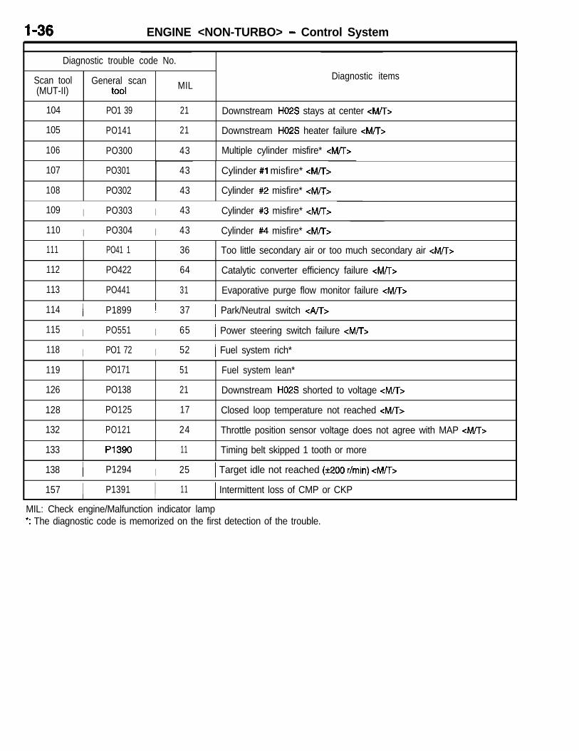
I-36 ENGINE <NON-TURBO> - Control System
Diagnostic trouble code No.
Scan tool General scan(MUT-II) tool MIL
104 PO1 39 21
105 PO141 21
106 PO300 43
Diagnostic items
Downstream H02S stays at center <MTT>
Downstream H02S heater failure <M/T>
Multiple cylinder misfire* <M/T>
107 PO301
108 PO302
43 Cylinder #l misfire* <M/T>
43 Cylinder #2 misfire* <M/T>
109 I PO303 I 43 Cylinder #3 misfire* <M/T>
110 I PO304 I 43 Cylinder #4 misfire* <M/T>
111 PO41 1
112 PO422
113 PO441
36 Too little secondary air or too much secondary air <M/T>
64 Catalytic converter efficiency failure <M/T>
31 Evaporative purge flow monitor failure <M/T>
114 I P1899 I 37 1 Park/Neutral switch <A/T>
115 I PO551 I 65 1 Power steering switch failure <M/T>
118 I PO1 72 I 52 / Fuel system rich*
119 PO171
126 PO138
128 PO125
132 PO121
133 P1390
51 Fuel system lean*
21 Downstream H02S shorted to voltage <M/T>
17 Closed loop temperature not reached <M/T>
24 Throttle position sensor voltage does not agree with MAP <M/T>
11 Timing belt skipped 1 tooth or more
138 I P1294 I 25 1 Target idle not reached (k200 r/min) <M/T>
157 I P1391 I 11 1 Intermittent loss of CMP or CKPI I I
MIL: Check engine/Malfunction indicator lamp*: The diagnostic code is memorized on the first detection of the trouble.

ENGINE <NON-TURBO> - Control Svstem I-37
MAIN MONITORS
To meet OBD II requirements, the on-board diagnos-tic system must monitor the electrical input signalsand the performance of output responses that canhave an effect on vehicle emissions. In addition,there are several “main monitors” that review theresult of system operations and their effect on emis-sions. The main monitors are as follows:l Catalystl Fuel Systeml Misfire0 Oxygen Sensorl Exhaust Gas Recirculationl Secondary air (air injection)
Oxygen Sensor Monitor
BackgroundEffective control of exhaust emissions is achievedby an oxygen feedback system. The most important
Each of the main monitors is listed below with abrief background explanation and a description ofhow the monitor operates. Following these condi-tions is the diagnostic trouble code (DTC) this moni-tor produces along with the DTC flashout numberand a number referred to as a SAE J 2012 or “Pcode. SAE J 2012 codes required by law for usewith generic diagnostic scan tools.
element in this system is the oxygen (02) sensormounted in the exhaust manifold.
h\

ENGINE <NON-TURBO> - Control Svstem
OperationOnce it reaches its operating temperature of 572”to 662”F, the sensor generates a voltage inverselyproportional to the amount of oxygen in the exhaust.This information is used by the PCM to calculatethe fuel injector pulse width necessary to providethe critical 14.7 to 1 air/fuel ratio (stoichiometric).A properly operating sensor must not only be ableto generate an output voltage across its operatingrange of 0 to 1 volt as it is exposed to different02 levels, it also must be able to detect thesechanges quickly. To detect a shift in the air/fuelmixture (lean or rich) the output voltage must changebeyond a threshold value. A malfunctioning sensorcould have difficulty changing beyond the thresholdvalue.While there are existing tests that determine if an02 sensor is shorted to voltage, contains an open
circuit, or does not function at all, prior to OBDII, it was impossible to identify sluggish or marginalsensors.A slow response rate or reduced voltage outputare all signs of an improperly operating oxygen sen-sor. This could mean longer instances of combustionof less than optimum air/fuel mixtures. This cansignificantly increase emissions.The 02 sensor must have a voltage output of greaterthan .67 volt in order to pass the test. It must alsoswitch more times over a 120 second period thana given threshold (to demonstrate quick response)or produce a given number of steep slope switches(demonstrating dynamic range and quick response)over the same time period. Data is not stored unlessidle time exceeds 10 seconds.
Front 02
High switchingfrequencyfast response
Front O2 ’I
Low switchingfrequencyslow response
E.Q2.-
WE
Trigger 1.5 x STD
Switching frequency

ENGINE <NON-TURBO> - Control System
02 Heater MonitorBackgroundIn order for the 02 sensor to function properly, the02 sensor must be heated to approximately 572“- 662°F. To assist the 02 sensor in achieving thistemperature, the O2 sensor is equipped with a Posi-tive Thermal Coefficient (PTC) heater element. Boththe upstream an downstream’s heater element isfed battery voltage any time the MFI relay is ener-gized. The ground for the heater element is routedthrough the 02 sensor’s 4-pin connector to an exter-nal ground source. As current flows through theelement, the temperature of the O2 sensor in-creases. As the temperature increases, the resis-tance of the element increases causing the current
OperationThe resistance of the 02 sensor changes with tem-perature and age. It’s resistance normally is between100 Sz to 4.5 MegR. When the temperature of thesensor is increased, the resistance of the sensordecreases. Inversely, as the sensor ages, the resis-tance increases. It is the resistance of the sensor’soutput circuit that is tested for proper heater opera-tion, not the heater element itself.
LThe test begins approximately 5 seconds after theengine has been turned off with the ignition keyand battery voltage greater than 10 volts (the PCMstill operates even though the key is in the off posi-tion). Once the timer has timed out, the PCM bias5 volts to the O2 sensors output wire once every1.6 seconds, and keeps it biased each time for35 ms. During this portion of the test, the PCMmonitors the voltage on the output wire of the 02sensor. As the sensor cools down, the resistanceshould increase, causing the PCM to register anincrease of voltage. The PCM determines a 02 sen-
flow to decrease. The 02 sensor’s heater maintainsthe temperature of the sensor to around 1200°F.After the engine has started, the upstream 02 sen-sor’s information is used by the PCM to assist inthe air/fuel calculation. If the sensor is not up tooperating temperatures, the information given bythe sensor may be inaccurate, possibly causingan increase in emissions.The downstream O2 sensor is used by the PCMto calculate the efficiency of the catalytic converter.The sensor must be heated to allow the 02 sensorto function normally. Without the O2 functioning nor-mally, the catalytic converter test would be invalid.
sor that has cooled enough by detecting an increaseof 0.49 - 1.56 volts higher what the PCM detectedat the beginning of the test. The maximum amountof time to perform this portion of the test is 144seconds.When the O2 sensor has cooled enough, the PCMenergizes the MFI relay for the next 48 seconds.With the relay energized, current should flow throughthe heater element causing an increase of tempera-ture at the sensor. As the heater warms the 02sensor, resistance of the 02 sensors output circuitshould decrease. As the resistance decreases, volt-age at the PCM decreases. While the MFI relayis energized, the PCM pulses the 5 volt biased signal30 times. Each time the biased voltage is activated,the PCM checks for a voltage drop. The 02 heatermonitor test passes if the PCM detects at least0.157 volt decrease in 15 out of the 30 pulsed sig-nals.

ENGINE <NON-TURBO> - Control System
Catalyst MonitorCurrent vehicles use a three-way catalytic converterto reduce emission of harmful gases. The convertersare referred to as three-way because they specifical-ly address three pollutants (hydrocarbons, carbon
Operation02 sensors located above (upstream) and below(downstream) the catalytic converter are able tomonitor the efficiency of the converter. The dual02 sensor strategy is based on the fact that asa catalyst deteriorates, it oxygen storage capacityand efficiency are both reduced. By monitoring the
monoxide, and nitrogen oxide) produced in the com-bustion chamber. The catalyst monitor uses a pair of inputs to indirectly measure just how effectivethe catalyst is at reducing emissions.
oxygen storage capacity of the catalyst, its efficiencycan be indirectly calculated. The upstream sensordetects the amount of oxygen in the exhaust gasbefore it enters the converter. This sensor shouldswitch fairly rapidly.
Upstream(primary) --.,Downstream
()ooo/ Engine
Exhaustgas
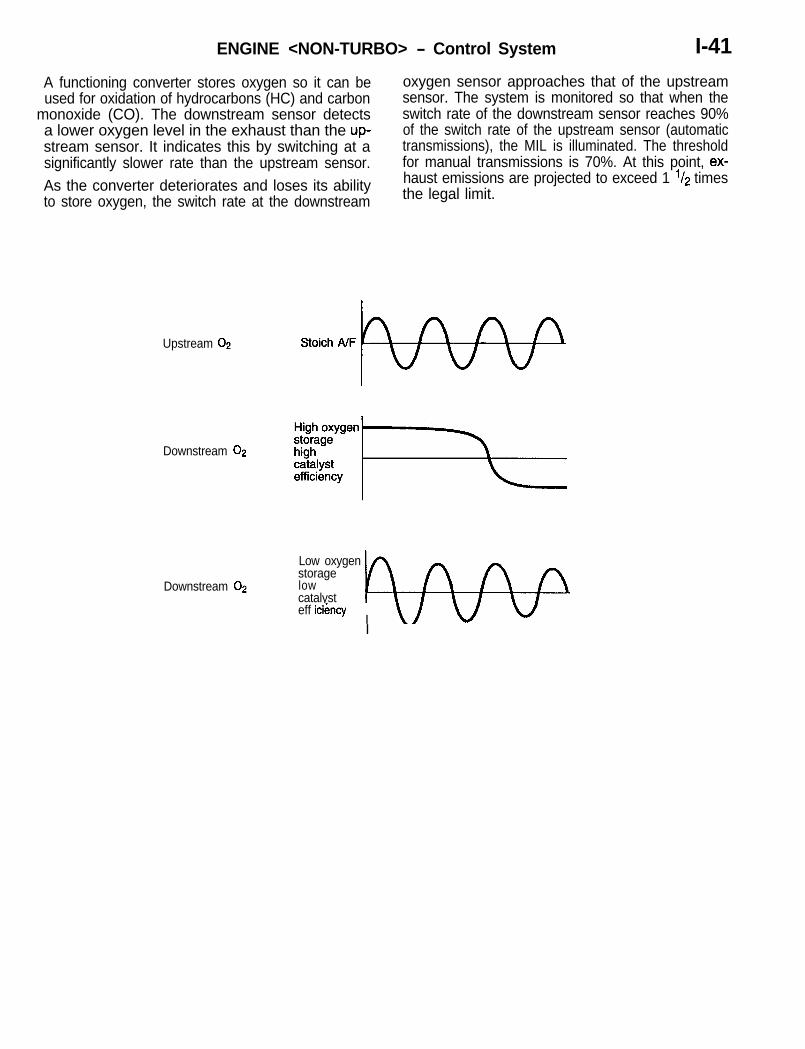
ENGINE <NON-TURBO> - Control System I-41
A functioning converter stores oxygen so it can be
Lused for oxidation of hydrocarbons (HC) and carbon
monoxide (CO). The downstream sensor detectsa lower oxygen level in the exhaust than the up-stream sensor. It indicates this by switching at asignificantly slower rate than the upstream sensor.As the converter deteriorates and loses its abilityto store oxygen, the switch rate at the downstream
oxygen sensor approaches that of the upstreamsensor. The system is monitored so that when theswitch rate of the downstream sensor reaches 90%of the switch rate of the upstream sensor (automatictransmissions), the MIL is illuminated. The thresholdfor manual transmissions is 70%. At this point, ex-haust emissions are projected to exceed 1 l/z timesthe legal limit.
Upstream 02 Stoich A/F /
Downstream 02 lzFgjE+
Low oxygenstorage
Downstream 02 lowcatalyst b- -eff icikncy
I \dw@I - -

1-42 ENGINE <NON-TURBO> - Control System
Fuel System MonitorBackgroundTo control the level of undesirable emissions, thefuel system must be able to maintain strict controlof the air/fuel ratio. Stoichiometry is the optimumair/fuel ratio, which is 14.7 to 1. At this point thebest balance between the production of HC’s andCO’s (which drop as the mixture becomes leaner)and NOx (which increases as the air/fuel mix be-
comes leaner) can be found. This is also the pointwhere the catalytic converter is most efficient atconverting all three gases to less harmful com-pounds. The goal of the PCM is to examine inputinformation and control outputs to produce aconstant stoichiometric ratio.
80-
80-
i/j
14:l 15:l 18:l
Air/fuel ratio
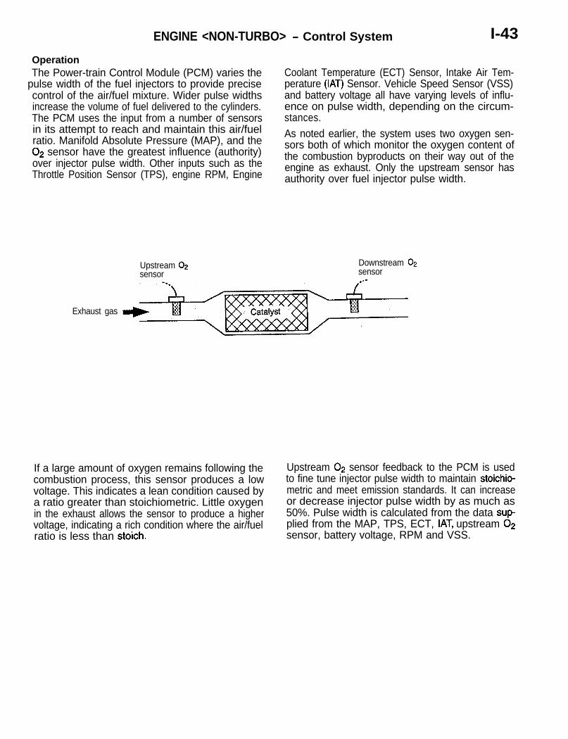
ENGINE <NON-TURBO> - Control System I-43
OperationThe Power-train Control Module (PCM) varies the
pulse width of the fuel injectors to provide precisecontrol of the air/fuel mixture. Wider pulse widthsincrease the volume of fuel delivered to the cylinders.The PCM uses the input from a number of sensorsin its attempt to reach and maintain this air/fuelratio. Manifold Absolute Pressure (MAP), and the02 sensor have the greatest influence (authority)over injector pulse width. Other inputs such as theThrottle Position Sensor (TPS), engine RPM, Engine
Upstream 02sensor
Coolant Temperature (ECT) Sensor, Intake Air Tem-perature (IAT) Sensor. Vehicle Speed Sensor (VSS)and battery voltage all have varying levels of influ-ence on pulse width, depending on the circum-stances.As noted earlier, the system uses two oxygen sen-sors both of which monitor the oxygen content ofthe combustion byproducts on their way out of theengine as exhaust. Only the upstream sensor hasauthority over fuel injector pulse width.
Downstream 02sensor
_.
Exhaust gas
If a large amount of oxygen remains following thecombustion process, this sensor produces a lowvoltage. This indicates a lean condition caused bya ratio greater than stoichiometric. Little oxygenin the exhaust allows the sensor to produce a highervoltage, indicating a rich condition where the air/fuelratio is less than stoich.
Upstream 02 sensor feedback to the PCM is usedto fine tune injector pulse width to maintain stoichio-metric and meet emission standards. It can increaseor decrease injector pulse width by as much as50%. Pulse width is calculated from the data sup-plied from the MAP, TPS, ECT, IAT, upstream 02sensor, battery voltage, RPM and VSS.

1-44 ENGINE <NON-TURBO> - Control Svstem
To control air/fuel ratio feedback, the PCM usesshort term correction and long term memory. Beforethe PCM can alter the programmed injector pulsewidth, it must enter closed loop operation. The re-quirements for closed loop operation are listed be-low:
l AN timers have timed out -following the STARTto RUN transfer (The length of these timersvaries with engine temperature)
l Engine temperature exceeds 35°Fl OS sensor is in the readv mode
35°F - 41 sec.50°F - 35 sec.70°F - 22 sec.
13) are used only during idle. Each cell represents
167°F - 11 sec.
a manifold pressure and rpm range and can be
Once in the closed loop control, the feedback sys-tems begin to operate. Short term memory workswith the long term memory, which is broken down
accessed with the MUT-II diagnostic scan tool.
into 14 different cells. Two of these cells (12 and
Long Term Memory Cells
ABOVE
2048
RPM
BELOW
Map Voltage
1 3 5PurgeFree*
0 2PurgeFree*
4
7 9
T6
11
10
1.38 2.0 2.64 3.26 3.9
13Idle
NeutralManual
TransaxlePurgeFree*
*PCM disables the canister purge function in these cells to gather data used for purge control and diagnostics.
For example:If the PCM were in cell 3, the MAP voltage mustbe between 1.38 and 2.OV and engine rpm must
be greater than 2048. This is the cell that the controlsystem would update.

ENGINE <NON-TURBO> - Control System I-45
If the oxygen sensor registers a rich or lean conditionwhile driving in this cell, the cell will require updatingto aid in fuel control. The short term correction isused first. It starts increasing pulse width quickly(kick), then ramps up slowly. Each control is in in-verse relation to the signal sent from the 02 sensor.
For example:The 02 sensor switches lean to rich. Short termcompensation kicks in lean, then ramps lean untilthe 02 sensor switches lean. At this point shortterm compensation reverses the process.
Stoich AIF ratio 14.7:1 .
If the oxygen sensor shows lean, the short termcompensation goes rich and multiplies the pulsewidth from long term memory in that cell by anamount greater than 1. If the sensor shows rich,the short term compensation drives the pulse widthnarrower by multiplying by a number less than 1(perhaps 0.97). The short term compensation canmultiply pulse width by as much as 1.25 or as littleas 0.75 to compensate for lean or rich conditions.
In this way, the short term compensation can in-crease pulse width by up to 25% (by multiplyingby 1.25) or decrease pulse width by up to 25%(by multiplying by 0.75).Example:Pulse width 0.05 x 1.25 = 0.0625 (increase of 25%)Pulse width 0.05 x 0.75 = 0.0375 (decrease of 25%)

Long term memory also has control over pulse widthby being able to increase or decrease the pulsewidth stored in the cell by up to 25%. Long termmemory is retained by the battery in the PCM, whileshort term correction is lost whenever the ignitionis turned off.The long term memory works to bring the shortterm correction to the point where the average per-
1-46 ENGINE <NON-TURBO> - Control System
cent of pulse width compensation it provides in thismemory cell is 0%. The long term memory returnsto this level of pulse width compensation the next time the vehicle enters this cell. It is in this waythat the PCM is continually relearning the most ap-propriate level of control, even as the vehicle ages,internal engine components wear, and operatingconditions change.
Short term fuelcompensation
StoichA/F ratio
Long term fuelcompensation
There are several “purge free” cells. These cellscontain information on how much effect the canisterhas on the air/fuel ratio. The purge solenoid is turnedon to shut off the purge flow and the cell is allowedto register any purge corruption. The monitor looksat the combination of short and long term fuel controlvalues to see if the system is in control.The fuel system is continuously monitored duringeach trip once the enabling conditions have been
met. Short term and long term values are multipliedtogether. The test fails if the fuel control systemreduces pulse width by 25% long term memory and7% short term compensation due to a rich conditionor increases pulse width by 25% long term memoryand 12% short term compensation due to a leancondition.

ENGINE <NON-TURBO> - Control System I-47
Misfire MonitorBackground
Misfire is defined by the California Air ResourcesOperation
Board as the lack of combustion in a cylinder dueThe OBD II misfire monitor uses information pro-
to absence of spark, poor fueling, compression,vided by the crank position sensor to determine
or any other cause. As a result, the air/fuel mixtureengine rpm and detect slight variations due to engine
will not burn, and during the exhaust stroke, it entersmisfire. Crankshaft rpm is calculated between the
the exhaust system. The raw fuel and excess oxygen69” and 9” falling edges of the crankshaft position
adversely affect the fuel system’s feedback mecha-sensor signal.
nism (the oxygen sensor) and can cause permanentdamage to the catalytic convertor.
2 revolutions
- 120”--I
iz 60” reference notch
Crank signal
I-48 ENGINE <NON-TURBO> - Control System
The threshold for determining what amount of rpmchange indicates misfire varies with engine speedand load. This is required because as engine speedincreases or load decreases, the overall effect ofa single cylinder misfire diminishes due to the mo-mentum of the crankshaft.The misfire monitor contains an adaptive featurethat can take into account component wear, sensorfatigue, and machining tolerances. The PCM notesrpm variance between cylinders during normal ve-hicle operation and then uses these figures as afoundation for calculating the threshold at whichrpm variance is considered to indicate misfire.NOTEThe PCM requires normal vehicle operation to up-date its memory. Because the PCM has no referencefor “normal operation”, the PCM considers a misfirecondition to be normal if installed in a vehicle thatis misfiring. The same situation can occur anytimebattery power to a PCM is lost and a vehicle ismisfiring when the controller is reconnected,The misfire monitor triggers operation of the MILin two different operating situations:
1,000 Rev Misfire
Misfire is continuously monitored (in 200 revolutionsegments) once the enabling conditions have beenmet. If the monitor detects misfire in more than1.6% of the engine cycles in a 1,000 revolutionperiod, a temporary fault is set. Freeze frame dataof the operating conditions during the last 200 rpmof that 1,000 revolution period are stored. As withother monitors, failure of the misfire monitor on thenext trip matures the code, the MIL illuminates, anda DTC is stored. It is important to note that twotrips are required for the code to mature. Continuedmisfiring during the initial trip does not illuminatethe MIL.
200 Rev Misfire
If the monitor detects misfire in more than 15%of cylinder firing opportunities during any 200 revolu-tion monitored segment, the MIL immediately beginsflashing, a DTC is started, and the freeze frameis stored with information regarding the conditionsat which the misfire occurred. This indicates thatengine misfire has reached the point where damageto the catalytic converter is likely to occur. The ve-hicle defaults to open loop operation to prevent theadaptive fuel controls from dumping additional fuelinto the cylinders and accelerating damage to thecatalyst. Driving the vehicle with the MIL flashingis not recommended.Once out of the operating condition where the 15%misfire is occurring, the MIL will stop flashing butremain illuminated. The vehicle may be driven, butshould be serviced immediately.Because some misfire is a common occurrencein a number of driving conditions, MIL illuminationdue to misfire may occur when no component hasfailed. Try to identify conditions that could triggerthe misfire monitor that are not related to componentfailure. Example of these are included below:
l Damp ignition system componentsl Low fuel/running out of gas (monitor triggers
as engine sputters)l “Lugging” the enginel Pulling heavy loadsl Low quality gasoline
In addition, the following situations could mistakenlytrigger the MIL:
l Large potholesl Extended rough road operation

ENGINE <NON-TURBO> - Control System I-49
Exhaust Gas Recirculation Monitor
L
BackgroundExhaust Gas Recirculation (EGR) is a method of reduce the high cylinder operating temperaturesreducing oxides of nitrogen (NOx) emissions by where NOx is most likely to occur. Lower combustionintroducing non-combustible exhaust gases into the chamber temperatures result in lower NOx emis-combustion chamber. These gases absorb heat and sions.
Upstream (primary)02 sensor
--..
Exhaust gas

I-50 ENGINE <NON-TURBO> - Control System
OperationThe EGR system consists of a vacuum solenoid,back pressure transducer and a vacuum operated
sure causes the transducer diaphragm to modulate.
valve. When activated, the solenoid allows vacuumThis allows intake manifold vacuum to reach the
to flow to the transducer. Negative exhaust back-EGR valve. The combination of vacuum on one
pressure allows manifold vacuum from the solenoidside of the valve diaphragm and exhaust back pres-
to vent to atmosphere. Positive exhaust backpres-sure on the other allows exhaust gases to beintroduced into the intake manifold.
transducer
EGR valve
An EGR system stuck in the closed position preventsthe system from decreasing NOx emissions. A sys-tern stuck in the open position can increase hydro-
carbon emissions, fuel consumption, and producerough engine operation.

ENGINE <NON-TURBO> - Control System I-51
The detect operation of the system, the solenoid
iis disabled and the 02 compensation control is moni-
tored. If ttie EGR system is operating properly, turn-ing’it off shifts the air/fuel ratio in the lean direction.
02 sensor data should indicate an increase in oxy-gen in the exhaust gases and cause the short termcontrol to shift rich. The amount of the shift indirectlymonitors the operation of the system.
EGR valve
OFF
Short term fuelcompensation .
Stoich A/F ratio
COMPREHENSIVE COMPONENTS
Refer to Group 13 - Troubleshooting in the Service Manual.

I-52 ENGINE <NON-TURBO> - Control System
DATA TRANSMISSION SYSTEMThe power train control module (PCM) and transaxlecontrol module (TCM) transfer control data to and
munication line and displays the data on the display.
from each other via a data communication system.(Various types of data are also received by the scan
The scan tool receives various tvpes of data fromtool from the power train control module througha line different from this data communication line.)
the transaxle control module through the data com-
Power train control module Transaxle control module
Bus+T <
The power train control module and transaxle controlmodule communicate with each other by alternatelysending the data in their respective modules to thedata bus.In other words, the power train control module sendsall its data to the data bus, and the transaxle control
module receives only those data items it needs fromthe bus. Then the transaxle control module sendsall its data to the data bus. The power train controlmodule does not require any specific data from thedata bus.

ENGINE <NON-TURBO> - Control System I-53
Bus+ and Bus- Circuits
LThe data transmission system has two wires con- from inducing electromagnetic interference (EMI)netted in parallel to the PCM and TCM. One circuit into the bus circuits.is Bus+, and the other is Bus-. For proper commu-nication, the wires must be twisted together at 1.75”
If the twists are not maintained throughout the bus
intervals. Twisting of the wires is intended to preventcircuits (at connectors and splices), false signals
switched-to-battery or switched-to-ground circuitscan be conveyed to all modules on the bus.
Communication chip (Communication Control Integrated Circuits)The bus circuits connect inside all modules to a com-munication chip. The illustration at left shows a repre-sentative communication chip block diagram. Forcommunication to occur, the bus must have Biasingand Termination (see the following sections.)
i
-------’ Transmit data
i

1-54 ENGINE <NON-TURBO> - Control System
5 volt supply
4
13kQresistor
{
Terminationresistor
13k&2resistor
7757
Biasing
Both bus circuits are biased (supplied voltage) toapproximately 2.5 volts. The Bus+ and Bus- circuitsare biased through a series circuit (see the illustrationat left). The bus current travels from a 5 volt sourcethrough a 13k ohm resistor to Bus-, then througha 120 ohm termination resistor to Bus+, and thento ground through a 13k ohm resistor. Bus bias isthe voltage required to operate the bus.If the system is functioning normally, the Bus- circuitvoltage is slightly higher than the Bus+ circuit voltage.This is normal, and is caused by the 120 ohm termina-tion resistor. The operating bus bias range is approxi-mately 1.5 - 3.5 volts. At voltage above or belowthis range, the bus has difficulty communicating cor-rectly.
Termination
The termination resistors are provided both the insideof PCM and the inside of TCM.For the bus circuit to be complete, at least one termina-tion point must exist.The resistance in the bus circuit is due to the termina-tion resistors. It can be measured with an ohmmeterat the data linkconnector by attaching the two ohmme-ter leads to the two bus wires. The ohmmeter willread 100 to 140 ohms for one controller with termina-tion and 40 to 80 ohms for two controllers with termina-tion.The termination points are inside of a controller butoutside the communication chip.
Inputs and Outputs
Messages sent over the communication system canbe considered both inputs and outputs. Output mes-sages from any one module are used as input mes-sages to the other modules on the communicationsystem.Input messages are used by the modules to imple-ment specific features. This arrangement allows morethan one module to use information from the samesensor. Another example of output messages arethose sent to the scan tool for diagnostic purposes.

ENGINE <NON-TURBO> - Control System 1-55
Bus CommunicationFor communication to occur, the following basicsare needed:a Bus+ and Bus- wires must be connected in
parallel to all modules.l Bus+ and Bus- wires are biased to approxi-
mately 2.5 volts.l Bus+ and Bus- wires must have at least one
point of termination.
Communication is based on voltage differential be-tween the two bus wires. The differential occurswhen two parts of the communication chip, the cur-rent sink and the current source, are used by thecommunication chip to control the bus current flow.Two different signal conditions can exist when thebus functions normally; there can be a “0” bit ora “1” bit.
$,;e;;’ ; OFF ; ON ; OFF 1 ON ;I ’I 2.52 ; 1 2.52 1
Bus+ ; 1 2.49 j I 2.49 I 1 1
Voltage
Bus- II 2.51 ; I 2.51 1 III II i[
2.481
/ ; 2.48 jBinary 1 0 I 1 I 0 I
1A F U 0 0 8 7 )
When the bus circuits are not allowing current toflow, there is a “1” condition. When the bus is idleand no messages are being sent, the bus is in the“1” condition.When the current source passes a small amountof current into the Bus+ wire, and the current sinkallows a small amount of current to be passed toground, there is a “0” condition.
Messages are made from a series of these “0” and“1” signals. Messages are generally transmitted ev-ery ten or more milliseconds.Each microprocessor on the bus is connected toa communication chip. The communication chipcommunicates to the CPU the messages transmittedand received on the bus.

1-56 ENGINE <NON-TURBO> - Engine Electrical
ENGINE ELECTRICALGENERATORThe generator is mounted on the right side of theengine, and is secured to the cylinder block witha pivot bracket and an adjustment bracket. Thepivot bracket is secured with three mounting bolts.The case is grounded to the block, and three electri-cal connections are provided for charging systemoperation.
STARTER MOTORThe starter motor is located on the left side of theengine. Locations to connect the battery positivewires are provided at the starter solenoid.
IGNITION SYSTEMThis engine uses the distributorless electronic igni-tion system. The distributor-less electronic ignitionsystem is referred to as the Direct Ignition System.Basic ignition timing is not adjustable. The power-train control module (PCM) determines spark ad-vance. The system’s three main components arethe coil pack, crankshaft position sensor, and cam-shaft position sensor.
The output voltage of the generator is regulatedby the power train control module.NOTEThe Power supply cable is connected to the genera-tor with a nut. The PCM voltage control circuit isthe smaller of the two-way connectors at the rearof the generator.
The crankshaft position sensor and camshaft posi-tion sensor are hall effect devices. The camshaftposition sensor and crankshaft position sensor gen-erate pulses that are inputs to the PCM. The PCMdetermines crankshaft position from these sensors.The PCM calculates injector sequence and ignitiontiming from crankshaft position. For a descriptionof both sensors; refer to Camshaft Position Sensorand Crankshaft Position Sensor in this section.

ENGINE <NON-TURBO> - Emission Control System I-57
EMISSION CONTROL SYSTEMGENERAL INFORMATIONThere are three sources of vehicle exhaust emis-sions generated: the exhaust gases resulting fromcombustion, the blow-by gases generated withinthe crankcase, and the evaporative emissions gen-erated from the fuel tank and other componentsof the fuel line.The emissions-control system, which is designedto control the discharge of these exhaust gasesinto the atmosphere, is composed of the followingsystem components.(1) Exhaust emission control system(2) Crankcase emission control system(3) Evaporative emission control system
Canister
Evaporative emissionpurge solenoid
r
From fuel pump
Positivecrankcaseventilationvalve
1+-
The exhaust emissions-control system reduces theamount of carbon monoxide, hydro carbon and ox-ides of nitrogen in the exhaust gases by addingthe exhaust gas recirculation device and the catalyticconverter to fundamental improvements such asan improvement of the combustion chamber andthe camshaft, as well as other improvements tothe engine such as feedback control of the air/fuelratio by the electronically controlled fuel injectionsystem.The crankcase emissions-control system is a closedtype so that blow-by gases are not discharged outto the atmosphere. The evaporative emissions-con-trol system is the canister type; vapors that aregenerated within the fuel tank are introduced intothe intake manifold and are cornbusted so that theyare not emitted out to the atmosphere.
/I Electric EGR
‘3transducer solenoid1 _ - _ _ ,
I i ,
MIT only 1- - - -
Pulskd secondaryair injection valve
Heated oxygensensor (rear)
i

1-58 ENGINE <NON-TURBO> - Emission Control Svstem
POSITIVE CRANKCASE VENTILATION SYSTEMThe positive crankcase ventilation system is a sys-tern for preventing the escape of blow-by gases
The positive crankcase ventilation valve is designed
from inside the crankcase into the atmosphere.to lift the plunger according to the intake manifold
Fresh air is sent from the air cleaner into the crank-vacuum so as to regulate the flow of blow-by gas
case through the breather hose to be mixed withproperly.
the blow-by gases inside the crankcase.In other words, the blow-by gas flow is regulated
The blow-by gas inside the crankcase is drawn intoduring low load engine operation to maintain engine
the intake manifold through the positive crankcasestability, while the flow is increased during high load
ventilation valve.operation to improve the ventilation performance.
Positive crankcaseventilation valve

ENGINE <NON-TURBO> - Emission Control System I-59
EVAPORATIVE EMISSION CONTROL SYSTEMIid
The evaporative emission control system preventsthe emission of fuel tankvapors into the atmosphere.When fuel evaporates in the fuel tank, the vaporspass through vent hoses or tubes to the charcoalfilled EVAP canister. The EVAP canister temporarilyholds the vapors. Through the EVAP purge solenoid,the power-train control module (PCM) allows intakemanifold vacuum to draw vapors into the combustionchambers during certain operating conditions. Thesolenoid regulates vapor flow from the canister tothe engine.
OPERATION
The EVAP purge solenoid regulates the rate of vaporflow from the EVAP canister to the throttle body.The PCM operates the solenoid.
During the cold start warm-up period and the hotstart time delay, the PCM does not energize thesolenoid. When de-energized, no vapors are purged.The PCM de-energizes the solenoid during openloop operation.The engine enters closed loop operation after itreaches a specified temperature and the pro-grammed time delay ends. During closed loop op-eration, the PCM energizes and de-energizes thesolenoid approximately 5 to 10 times per second,depending upon operating conditions. The PCM va-ries the vapor flow rate by changing solenoid pulsewidth. Pulse width is the amount of time the solenoidde-energizes.
PULSED SECONDARY AIR INJECTION SYSTEMOnly manual transaxle vehicles have a pulsed sec- OPERATIONondary air injection system. The system injects freshair upstream of the catalytic convertor. It operates
The PCM controls the ground path for the solenoid.
for a short period after cold engine start-up untilWhen the PCM grounds the solenoid, fresh air from
the engine coolant temperature reaches approxi-the air cleaner flows through the aspirator valve
mately 5% (125°F)to the catalytic convertor.
The secondary air injection system contains:The aspirator valve prevents exhaust gases fromflowing into the fresh air stream, at the air cleaner
l Pulsed secondary air injection valvel Pulsed secondary air injection solenoidl Connecting hoses and tubes
when the solenoid is grounded. If the aspirator valvemalfunctions, a popping noise could be heard duringcold start throttle stabs.
Pulsed secondaryPulsed secondaryair injection solenoid
I
I

I-60 ENGINE <NON-TURBO> - Emission Control System
EXHAUST GAS RECIRCULATION (EGR) SYSTEMThe exhaust gas recirculation (EGR) system lowersthe nitrogen oxide (NOx) emission level. When theair/fuel mixture combustion temperature is high, alarge quantity of nitrogen oxides (NOx) is generatedin the combustion chamber. Therefore, this systemrecirculates part of emission gas from the exhaustport of the cylinder head to the combustion chamberthrough the intake manifold to decrease the air/fuelmixture combustion temperature, resulting in reduc-tion of NOx.
OPERATIONThe electronic EGR transducer (EET) contains anelectrically operated solenoid and a back-pressuretransducer. The PCM operates the solenoid. ThePCM determines when to energize the solenoid.Exhaust system back-pressure controls the trans-ducer.When the PCM energizes the solenoid, vacuumdoes not reach the transducer. Vacuum flows tothe transducer when the PCM energizes the sole-noid. When exhaust system back-pressure becomeshigh enough, it fully closes bleed valve in the trans-
The EGR flow rate is controlled by the EGR valveso as not to decrease the driveability.The EGR system contents:l EGR tubel EGR valvel Electronic EGR transducer (EET)l Connecting hoses
ducer. When the PCM energizes the solenoid andback-pressure closes the transducer bleed valve,vacuum flows through the transducer to operatethe EGR valve.Energizing the solenoid, but not fully closing thetransducer bleed hole (because of low back-pres-sure), varies the strength of vacuum applied to theEGR valve. Varying the strength of the vacuumchanges the amount of EGR supplied to the engine.This provides the correct amount of exhaust gasrecirculation for different operating conditions.

ENGINE <NON-TURBO> - Mount 1-61
MOUNT<I The engine mounts use a principal axis inertia sup-
port system.This support method on the principal axis inertiais a structure that supports the top of the engine
FEATURESl The mount elements are arranged near the roll
axes of the engine and transaxle so that therolling moment can be limited and vibrationscan be reduced during idling.
l The front and rear roll stopper brackets havebeen relocated to the transaxle housing. Asa result, the bracket has been made shorterand more rigid, which contributes to less vibra-tion and noise.
l Each insulator with internal hollows has out-standing vibration absorbing characteristics.
and top of the transaxle to effectively control enginevibration.
l Brackets cast from aluminum are used for theengine mounts and transaxle mounts so as toreduce booming noise.
l Conventional arrangement of the engine andtransaxle has been reversed to mount the en-gine on R.H. side of the vehicle and the transaxleon the L.H. side, resulting in reversal of thepositions of the respective mounts.
Dynamicdamper LI ,yu 1.z
H mountb wossmemuer Dynamic Engine
damp&& Transaxle
FrontRear rollstopper
Centermember
Transaxle Imount
stopper Centermember
uCrossmember
i

I-62 ENGINE <NON-TURBO> - Acceleration System
ACCELERATION SYSTEMACCELERATOR PEDAL AND ACCELERATOR CABLEThe accelerator system is a cable and suspendedpedal combination.
The accelerator pedal side end of the cable is pro-vided with a plastic bushing which effectively sup-presses the noise that would result from direct con-tact of the cable and the accelerator arm.
Plasticbushing
I ’ ’

ENGINE <NON-TURBO> - Acceleration System I-63
AUTO-CRUISE CONTROL SYSTEMBy using the auto-cruise control, the driver can driveat the speed he likes [in a range of approximately56 to 137 km/h (35 to 65 mph)] without depressingthe accelerator pedal.The actuator system consists of a reservoir assem-bly and a speed control assembly. The actuatoris operated by intake manifold vacuum.
The control unit is incorporated in the engine controlmodule. Transmission of information including ve-hicle speed and engine speed is accomplished inthe inside of the module.
Control switch
Intermediate link Main switch
Vehicle speedsensor CM/T>
Park/Neutral position IYswitch <A/T> Engine control module Reservoir assembly
Main switch y
Auto-cruise control indicator
Control switch

I-64 ENGINE <TURBO> - General Information
ENGINE <TURBO>
GENERAL INFORMATIONThis 4G63-DOHC engine with turbocharger is essentially the same as the one currently used for Eclipse.
MAJOR SPECIFICATIONS
Items Specifications
Total displacement cm3 (cu.in.) 1,997 (121.9)
Bore x Stroke mm (in.) 85.0 (3.35) x 88.0 (3.46)
Compression ration 8.5
Combustion chamber Pentroof type
Camshaft arrangement DOHC
Valve timingIntake
Open 21’ BTDCClose 51’ ABDC
ExhaustOpen 57” BBDCClose 15” ATDC
Fuel system Electronic control multipoint fuel injection
Rocker.arm Roller type
Lash adjuster Equipped

ENGINE <TURBO> - Cooling System
COOLING SYSTEM
iThe cooling system is of the water-cooled, forcedcirculation type with the following features:l A small-size, high-performance radiator has
been adopted for better cooling efficiency andless weight.
l Reduction in size of the automatic transaxleoil cooler had resulted in a lowered radiatorposition, which has permitted the “slant nose”design of the body.
l The cooling fan control has been integratedinto the centralized control by the engine controlmodule for better cooling efficiency, better fuelconsumption, less noise, and better accelera-tion. (For detailed information on the controls,refer to P.l-76.)
l The system uses an “inlet coolant temperaturemethod” which is achieved by locating the ther-mostat at the coolant inlet side of the engine.
COOLANT FLOW
When engine is cold (Thermostat closed):
Cylinder head
Throttle bodyI
1 Water inlet pipe k Heater Thermostat case1-I 1 (Thermostat) 1
Turbocharger
When engine is hot (Thermostat open):
Cylinder head
Throttle body
Water inlet pipe Heater
Turbocharger
i

1-66 ENGINE <TURBO> - Cooling System
SPECIFICATIONS
Items
Cooling method
RadiatorType
ThermostatWater pump
TypeDrive method
Specifications
Water-cooled pressurized, forced circulationwith electrical fan
Pressurized corrugated fin typeWax pellet type with jiggle valve
Impeller of centrifugal typeDrive belt
CONSTRUCTION
Radiator fan assembly
An-(Air cooled) AIT oil cooler hose and pipe

ENGINE <TURBO> - Intake and Exhaust I-67
INTAKE AND EXHAUST INTAKE MANIFOLD AND EXHAUST MANIFOLD
The intake and exhaust manifolds are basically thesame as the once currently used.
EXHAUST PIPEThe exhaust pipe consists of three parts: a frontpipe, a center pipe, and a main muffler with mufflercutter. It is mounted on the body via rubber hangers
CONSTRUCTION
<FWD>
Pre-muffler/
to minimize vibration transmission from the exhaustsystem to the body. A large main muffler, sub mufflerand pre-muffler reduce exhaust noise.
Muffler cutter
Sub muffler
\
/Main muffler
Heated oxygen sensor
F&t pipe
<AWD>Muffler cutter
/I
Flexible pipe
Center pipe
Front pipe

1-68
FUEL SYSTEM
ENGINE <TURBO> - Fuel System
The fuel system of the 4G63 engine consists ofelectrcmagnetic fuel injectors, a fuel rail, a fuel pres-
sure regulator, an electric motor-driven fuel pump,fuel filter and fuel tank.
FUEL FLOW DIAGRAM
4
Intake manifold
b
-
I /I\ II\ II\ I
,i Fuel tankA-
I IFuel
CONFIGURATION DIAGRAM
Fuel cut-off
Evaporativeemissioncanister
Fuel rail

ENGINE <TURBO> - Fuel System I-69
FUEL TANK<FWD>
The fuel tank is the same as the one of the 420Aengine. (Refer to P. 1-12.)
<AWD>
The fuel tank is made from a high density polyethyl-ene (HDPE) material and blow-formed into an inte-gral tank.The tank has an internally installed pump and gaugeassembly and pipe and gauge assembly. In addition,a fuel cut-off valve assembly is provided to preventthe leakage of the fuel that would occur when thevehicle rolls over.
Pump and gauge assembly
\
Features cAWD>
l Light weight - 20% weight reduction ascompared with a steel tank
l Increased tank capacity due to improved spaceefficiency
l Highly rust-resistantl Use of a resin cap for better serviceabilityl Saddle-shaped tank striding across the exhaust
and power transmission systems for effectiveuse of the space under the body
I I
Saddle-shaped tank
Fuel tank Protector

I-70 ENGINE <TURBO> - Control System
CONTROL SYSTEMGENERAL INFORMATIONExcept the following improvements, the MFI system is essentially the same as the one used on the 19944G63 2.0-liter DOHC engine.
Major improvements Remarks
ECU control of the generator is adopted. Improves idling speed stability electric loads.
ECM control of radiator fan and condenser fan isadopted.
Basically the same as the one introduced on the 1994Galant.
I Diagnostic system conforming to OBD-II is adopted. I I
Manifold Difference Pressure (MDP) sensor added todetect changes in manifold vacuum.
This supports OBD-II EGR monitoring.

ENGINE <TURBO> - Control System
SYSTEM BLOCK DIAGRAM
Sensors Engine control module (ECM)
Volume air flow sensor --b Fuel injection controlI 1 It I I
Intake air temperature sensor I-1I II
Barometric pressure sensor b
Engine coolant temperature sensor +Idle air control
Throttle position sensor b
Closed throttle position switchIgnition timing control
Engine and transaxletotal control 1
Crankshaft position sensor bPower supply control
Camshaft position sensorF u e l p u m p c o n t r o l,
Heated oxygen sensor (front, rear) -+ Air conditioning compressorclutch relay control
Vehicle speed sensor (reed switch) +Fuel pressure control
Air conditioning switch bIntake charge pressure control
‘ti Air conditioning pressure switchI
bTurbo meter controlI
Power steering pressure switch b
Electric load switch b
Park/Neutral position switch <AIT> +
Ignition switch-IG + Ey;‘purge solenoid
Knock sensor .----b EGR solenoid control
Transaxle control module (TCM) -W Volume air flow sensorreset signal control
Manifold differential pressure (MDP)sensor
,
Cooling fan control
Generator FR terminal bGenerator current control
Ignition timing adjustment terminal b
Oxygen sensor heater controlIgnition power transistor unit b
I , I
Diagnostic control terminal
Power supply
1x1 ;;IEd diagnostic (OBD)
Actuators
-1 No. 1 injector
-1 No. 2 injector
--+I No. 3 injector
-1 No. 4 injector
Idle air control motor-’ (stepper motor)
Ignition coil- (ignition power transistor)
Multiport fuel injection- (MFI) relay
- Air conditioning compressorclutch relay
___*I Fuel pressure solenoid
---+ Turbocharger waste gate solenoid
& Turbo meter
-1 EVAP purge solenoid
- EGR solenoid
__+I Volume air flow sensor
Radiator fan motor relay and air- conditioning condenser relay
-1 Generator G terminal
d Oxygen sensor heater
Check Engine/Malfunction- injector lamp
-1 Diagnostic output terminal I

1-72 ENGINE <TURBO> - Control System
SYSTEM DIAGRAM
+l Heated oxygen sensor (Front)*2 Volume air flow sensor*3 Intake air temperature sensor~4 Throttle position sensor+5 Closed throttle position switch6 Camshaft position sensor217 Crankshaft position sensor*8 Barometric pressure sensorSl Engine coolant temperature sensor+lO Knock sensor*II Heated oxygen sensor (Rear)~12 Manifold differential pressure sensor0 Power supplyl Vehicle speed sensorl A/C switch0 Park/Neutral position switch cm>0 Power steering pressure switch0 Ignition switch-ST
Intake air temperature sensor
Volume air flow \
r al injectora2 Evaporative emission purge solenoida3 Idle air control motora4 EGR solenoida5 Ignition coil, ignition power transistora6 Fuel pressure solenoida7 Turbocharger waste gate solenoidl Fuel pump relayl Multiport fuel injection (MFI) relayl Air conditioning compressor clutch relayl Check engine/Malfunction indicator lampl Diagnostic output
L
Idle air control motorI
Purge control valve
I Evaporativeemissioncanister
;~;~ttJ3p~;i$msyor \1 myhFast “le air valve , I -
Evaporativeemissionwwsolenoid
A9 Engine coolant temperature sensor
*I 0 Knock sensor
Heated <&ensensor (rear)
TWC/
Heated oxygensensor (front)
irankshaft position sensor
Camshaft position sensor

ENGINE <TURBO> - Control System I-73
SENSORSGENERATOR FR TERMINAL
x Trio diode
Generator
L - - - _ - - - - - - - - - - - - - - - - - - - - - - - - - - - - - - -Voltage regulator I 1 .
Terminal FR of the generator inputs the ON/OFFstate of the generator field coil to the engine controlmodule. In response to this signal, the engine controlmodule senses the generator output current, anddrives the ISC servo according to the output current(electric load). This prevents a change in idlingspeed that may otherwise be caused by the electricload.* The generator generates power when the power
transistor in the voltage regulator is caused tobe ON to supply a current (field current) to thefield coil. When the power transistor is causedto be OFF, the power generated by the generatorrapidly decreases. The size of the generatoroutput current, therefore, depends on the ratiothat the power transistor is ON (ON duty). The
Engine control module
voltage at terminal FR is low when the powertransistor is ON, and high when the power tran-sistor is OFF. Therefore, the ON duty of thepower transistor ini the voltage regulator or thegenerator output current can be sensed by cal-culating the ratio that the voltage at terminalFR is low.When the generator output voltage reaches theregulated voltage (approx. 14.4V), the voltageregulator switches the power transistor fromON to OFF. When ithe output voltage falls belowthe regulated voltage, the voltage regulatorswitches the power transistor from OFF to ON.In this manner, the generator output voltageis maintained constant.

1-74 ENGINE <TURBO> - Control System
ACTUATORS AND CONTROLFAN MOTOR RELAY (RADIATOR AIR CONDITIONING CONDENSER)This relay controls the radiator fan and air condition- control module.ing condeser fan based on signals from the engine
GENERATOR G TERMINALThe engine control module limits the generator out-put current by duty control of the continuity between
generator terminal G and the ground.
--
I+ Trio diode
1 $-/$-I+ / 1: - - - - - - - - &--------- - ’ ’ - a ’ - ’ =
II-+,c o i l
u-. x f
I---FieldI coilII I
’ ‘d \-I I L ---_----_-------------- -------_ ---_
-----JI Voltage regulator \ 111 3.
Generator \-_I
S terminal voltage: 14.4 V or more Engine control module
When there is no continuity between generator ter-minal G and the ground (let this be 100% duty),transistor No. 1 (Trl) stays in the always ON state.When the voltage at generator terminal S reaches
14.4 V, the power transistor is forced to OFF toadjust the generator output voltage to 14.4 V. Thisoperation is the same as that of the conventionalgenerator.

ENGINE <TURBO> - Control System I-75
Voltage regulator
GeneratorS terminal voltage: 12.3 V or more Engine control module
When generator terminal G is short-circuited to theground (let this be 0% duty), the Trt stays in thealways OFF state. In this case, when the voltageat generator terminal S reaches 12.3 V, the power
transistor is forced to OFF to adjust the output volt-age to 12.3 V. Since the voltage is lower thancharged battery voltage, practically no current flowsfrom the generator.

I-76 ENGINE <TURBO> - Control Svstem
COOLING FAN CONTROLThis sytem is similar to the one introduced on the1994 Galant.Two transistors inside the engine control modulecontrol the radiator fan and the air conditioning con-denser fan motor according to the engine coolanttemperature and the vehicle speed. When the airconditioning switch and air conditioning pressureswitch are ON, the fan motor rotate at high speed
regardless of the engine coolant temperature andvehicle speed.l When the engine coolant temperature is faulty,
the fan motors (radiator and condenser) aredriven at high speed.The engine control module also controls thefan suitable to the various driving conditions- cruising, accelerating and decelerating, etc.
Ignition switchBattery
I Radiatorfan motorrelay
FIesistor
Radiatorfan motor
relay relay
L
I /\, 0 1
(Low speedtransistor)
(High speedtransistor)
ECM
Engine coolant temperatUre Sensor.
Throttle position sensor.
Closed throttle position switch.
Crankshaft position sensor.
Vehicle speed sensor.
Air conditioning switch.
Air conditioning pressure switch.
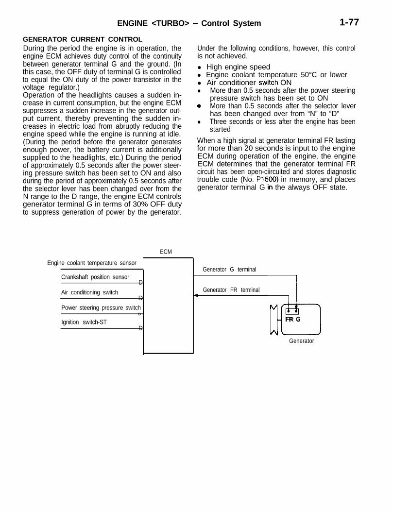
ENGINE <TURBO> - Control System 1-77
GENERATOR CURRENT CONTROL
L
During the period the engine is in operation, theengine ECM achieves duty control of the continuitybetween generator terminal G and the ground. (Inthis case, the OFF duty of terminal G is controlledto equal the ON duty of the power transistor in thevoltage regulator.)Operation of the headlights causes a sudden in-crease in current consumption, but the engine ECMsuppresses a sudden increase in the generator out-put current, thereby preventing the sudden in-creases in electric load from abruptly reducing theengine speed while the engine is running at idle.(During the period before the generator generatesenough power, the battery current is additionallysupplied to the headlights, etc.) During the periodof approximately 0.5 seconds after the power steer-ing pressure switch has been set to ON and alsoduring the period of approximately 0.5 seconds afterthe selector lever has been changed over from theN range to the D range, the engine ECM controlsgenerator terminal G in terms of 30% OFF dutyto suppress generation of power by the generator.
ECM
Engine coolant temperature sensor
Crankshaft position sensorD
Air conditioning switchD
Power steering pressure switchD
Ignition switch-STD
Under the following conditions, however, this controlis not achieved.l High engine speedl Engine coolant ternperature 50°C or lowerl Air conditioner swiitch ONl More than 0.5 seconds after the power steering
pressure switch has been set to ONo More than 0.5 seconds after the selector lever
has been changed over from “N” to “D”l Three seconds or less after the engine has been
startedWhen a high signal at generator terminal FR lastingfor more than 20 seconds is input to the engineECM during operation of the engine, the engineECM determines that the generator terminal FRcircuit has been open-ciircuited and stores diagnostictrouble code (No. P1500) in memory, and placesgenerator terminal G iin the always OFF state.
Generator G terminal
Generator FR terminalI
-I
llrElFR G
Generator

1-78 ENGINE <TURBO> - Control System
DIAGNOSTIC SYSTEMDESCRIPTION OF OBD-II SYSTEM
The engine control module (ECM) monitors its input/output signals. Some signals are monitored all thetime, and others only under specified conditions.When an irregularity has continued for a specifiedtime from when the irregular signal is initially moni-tored, the engine control module judges that a faulthas occurred.After detecting a fault, the engine control modulestores its diagnostic trouble code in memory whenit re-detects the same fault in an operation followingthe next engine startup.In regard to the items marked *, however, the enginecontrol module stores the diagnostic trouble codeof any of them the first time the module detectsit.There are 35 diagnostic items, and the diagnosticresults can be read out with a scan tool.Moreover, since memorization of the diagnostictrouble codes is backed up directly by the battery,the diagnostic results are memorized even if theignition key is turned off. The diagnostic troublecodes will, however, be erased when the batteryterminal or the engine control module connectoris disconnected.In addition, the diagnostic trouble code can be alsobe erased by turning the ignition switch to ON andsending the diagnostic trouble code erase signalfrom the scan tool to the engine control module.NOTEIf the sensor connector is disconnected with theignition switch turned on, the diagnostic trouble code
Data item
Engine coolant temperature
Engine speed
Vehicle speed
Long term fuel trim
Short term fuel trim
Fuel control state
Calculated load value
Diagnostic trouble code associated with the data inmemory
is memorized. In this case, send the diagnostictrouble code erase signal from the scan tool to theengine control module and the diagnostic memorywill be erased.The 35 diagnostic items are provided as follows,and if plural items are activated, they are all indicatedsequentially from the smallest code number.NOTEThe diagnostic trouble code of ignition timing adjust-ment signal is outputted when terminal for ignitiontiming adjustment is grounded. Therefore, it is notabnormal that the code is outputted even when ter-minal for ignition timing adjustment is grounded forignition timing adjustment.The engine control module stores in memory notonly the diagnostic trouble code of a fault but alsothe intra-module RAM data on the engine operatingconditions that existed when it detected the fault.(The data is called freeze frame data.)The data shows the engine operating conditionsthat existed when the engine control module de-tected the fault as well as those that existed whenthe module did not detect any fault.However, when the engine control module detectsa misfiring or fuel trim malfunction, it clears theexisting data and stores the new data.The data can be read by a scan tool and can beconveniently used in performing fault repetition testsfor troubleshooting.The data items to be stored in memory are shownbelow.
Unit
“C
r/min.
km/h
%
%
0 Open loopl Closed loopl Open loop - drive conditionl Open loop - DTC setl Closed loop - 02 (rear) trouble
%
-

ENGINE <TURBO> - Control System l-79
Items indicated by Check Engine/Malfunction indicator lamp
NOTE 2. After lighting the Engine Check/Malfunction indi-1. After detecting a fault, the engine control module cator lamp, the ECfvI turns it off when the ECM
(ECM) lights the Check Engine/Malfunction indi-cator lamp when it re-detects the same faultin an operation following the next engine start.In regard to the items marked *, however, theECM lights the Check Engine/Malfunction indi-cator lamp the first time the ECM detects anyof them.
does not detect the same fault in three consecu-tive operations (provided that the operationsare inclusive of power train component monitorand that if the fault is a misfiring or fuel trimmalfunction, it occurs at the second and subse-quent times under much the same operatingconditions as at the first time), each followingan engine start.
Engine control module (ECM) malfunction
Volume air flow circuit malfunction
Barometric pressure circuit malfunction
Intake air temperature circuit malfunction
Engine coolant temperature circuit malfunction
Throttle position circuit malfunction
Excessive time to enter closed loop fuel control*
O2 sensor circuit malfunction (bank 1 sensor 1)
O2 sensor heater circuit malfunction (bank 1 sensor 1)
O2 sensor circuit malfunction (bank 1 sensor 2)
02 sensor heater circuit malfunction (bank 1 sensor2)
Fuel trim malfunction (bank 1)
Injector circuit malfunction - cylinder 1
injector circuit malfunction - cylinder 2
Injector circuit malfunction ‘- cylinder 3
Injector circuit malfunction .- cylinder 4
Random misfire detected*
Cylinder 1 misfire detected*
Cylinder 2 misfire detected*
Cylinder 3 misfire detected*
Cylinder 4 misfire detected*
Crankshaft position sensor circuit malfunction
Camshaft position sensor circuit malfunction
Exhaust gas recirculation fllow malfunction
Catalytic efficiency below tlhreshold (bank 1)
Evaporative emission control system malfunction
Idle control system malfunction
Transmission*
CautionWhen the Check Engine/Malfunction indicatorlamp lights because of a fault in the ECM, nodiagnostic trouble code can be read because
of disruption of communications between thescan tool and ECM.

ENGINE <TURBO> - Control System
DIAGNOSTIC TROUBLE CODES
The diagnostic items are shown in the following table.
Diagnostic trouble code No.
General scan toolmode Scan tool mode
PO1 00 PO100
PO105 PO105
PO110 PO110
PO115 PO115
PO1 20 PO120
PO1 25 -
PO1 30 -
PO1 35 -
PO136
PO141
PO1 70 -
PO201 PO201
PO202 PO202
PO203 PO203
PO204 PO204
PO300
PO301 -
PO302
PO303
PO304
PO325 PO325
PO335 PO335
PO340 PO340
PO400 - 1
PO420
PO440 -
PO443
Diagnostic items
Volume air flow circuit malfunction
Barometric pressure circuit malfunction
Intake air temperature circuit malfunction
Engine coolant temperature circuit malfunction
Throttle position circuit malfunction
Excessive time to enter closed loop fuel control*
02 sensor circuit malfunction (bank 1 sensor 1)
02 sensor heater circuit malfunction (bank 1 sensor 1)
02 sensor circuit malfunction (bank 1 sensor 2)
02 sensor heater circuit malfunction (bank 1 sensor 2)
Fuel trim malfunction (bank 1)
Injector circuit malfunction - Cylinder 1
Injector circuit malfunction - Cylinder 2
Injector circuit malfunction - Cylinder 3
Injector circuit malfunction - Cylinder 4
Random misfire detected*
Cylinder 1 misfire detected*
Cylinder 2 misfire detected*
Cylinder 3 misfire detected*
Cylinder 4 misfire detected*
Knock sensor 1 circuit malfunction
Crankshaft position sensor circuit malfunction
Camshaft position sensor circuit malfunction
Exhaust gas recirculation flow malfunction
Catalyst efficiency below threshold (bank 1)
Evaporative emission control system malfunction
Evaporative emission control system purge control valve circuitmalfunction
PO500 PO500 Vehicle speed sensor malfunction
NOTE:*: ECM stores the DTC in memory at the first detection of the malfunction.

ENGINE <TURBO> - Control Svstem
Diagnostic trouble code No.
General scan toolmode Scan tool mode
Diagnostic items
PO505
PO700
P1300
P1400
-
PO600
P1300
Idle control system malfunction
A cable from transmission control module for transmission oftorque reduction signal
Transmission*
Ignition timing adjustment circuit malfunction
Manifold Differential Pressure (MDP) sensor circuit malfunction
1 Generator FR terminal circuit malfunction
NOTE:*: ECM stores the DTC in memory at the first detection of the malfunction.
SERVICE DATA REFERENCE TABLEThere are two modes for reading service data, general scan tool mode and scan tool (MUT-II) mode.The service data readable in each mode is as follows.
Item No. Inspection item
11 Heated oxygen sensor (Front)
12 Volume air flow sensor
13 Intake air temperature sensor
14 Throttle position sensor
16 Power supply voltage
18 Cranking signal (Ignition switch-ST)
21 Engine coolant temperature sensor
22 Crankshaft position sensor
2 4 Vehicle speed sensor
25 Barometric pressure sensor
26 Closed throttle position switch
27 Power steering pressure switch
28 A/C switch
29 Park/Neutral position switch <A/T>
33 Electrical load switch
41 Injectors
44 Ignition coils and ignition power transistor
45 Idle air control (stepper) position
49 A/C compressor clutch relay
X X
X X
X X
X X
X
X
X X
X X
X
X
X
X
X
X
X
X
X
X
X
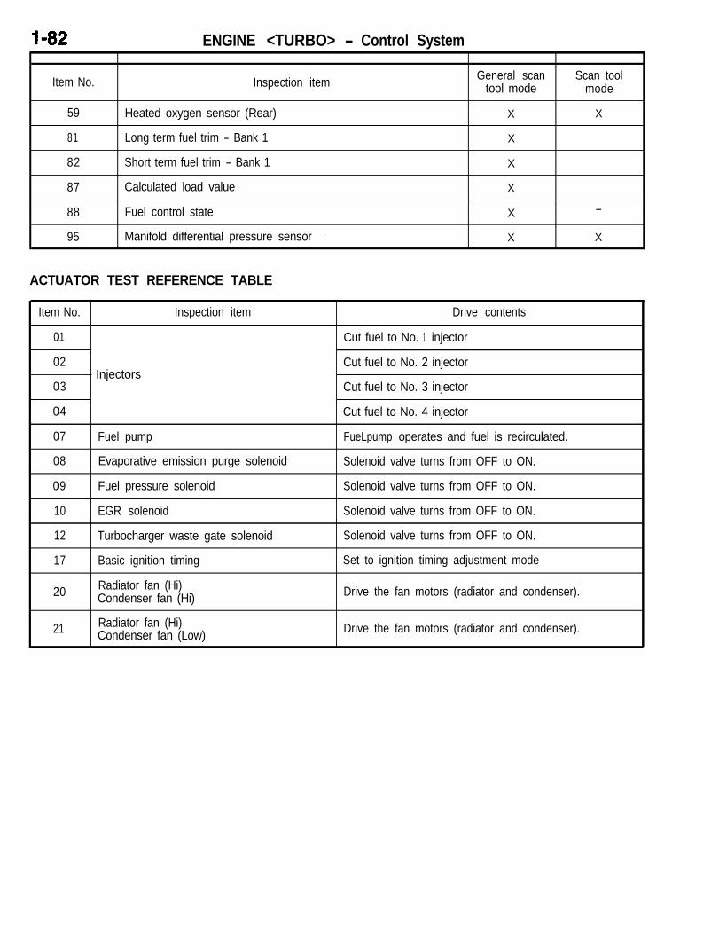
ENGINE <TURBO> - Control System
Item No. Inspection item General scan Scan tooltool mode mode
59 Heated oxygen sensor (Rear) X X
81 Long term fuel trim - Bank 1 X
82 Short term fuel trim - Bank 1 X
87 Calculated load value X
88 Fuel control state X -
95 Manifold differential pressure sensor I X X
ACTUATOR TEST REFERENCE TABLE
Item No. Inspection item Drive contents
01 Cut fuel to No. 1 injector
02- Injectors
Cut fuel to No. 2 injector
03 Cut fuel to No. 3 injector
04 Cut fuel to No. 4 injector
07 Fuel pump FueLpump operates and fuel is recirculated.
08 Evaporative emission purge solenoid Solenoid valve turns from OFF to ON.
09 Fuel pressure solenoid Solenoid valve turns from OFF to ON.
10 EGR solenoid Solenoid valve turns from OFF to ON.
12 Turbocharger waste gate solenoid Solenoid valve turns from OFF to ON.
17 Basic ignition timing Set to ignition timing adjustment mode
20 Radiator fan (Hi)Condenser fan (Hi) Drive the fan motors (radiator and condenser).
21 Radiator fan (Hi)Condenser fan (Low) Drive the fan motors (radiator and condenser).

ENGINE <TURBO> - Control Svstem I-83
MAIN MONITORS
LCATALYST MONITORING(1) Monitoring method
l Conversion efficiency is monitored on theFTP (Federal Test Procedure) basis.
l Calculate a frequency ratio (RF) of outputsignals, oscillating from lean to rich or viceversa, from the front and rear 02 sensorsaccording to the following equation.
(2) Malfunction criteriaIf RF becomes larger than the predeterminedvalue, a catalyst malfunction is indicated.
Output signal frequency of rear O2 sensorRF =
Output signal frequency of front O2 sensor
MISFIRE MONITORING
(1) Monitoring methodFluctuation of crankshaft speed is monitored.
(2) Malfunction criteriaIf the fluctuation of the crankshaft rotation islarger than the predetermined value, an enginemisfire is indicated.
But the determination of misfire is masked undersome conditions like rough-road driving to avoidfalse diagnostic trouble codes.
(3) System figure
Damperpul
Crank sprocket
UL-

I-84 ENGINE <TURBO> - Control System
OXYGEN SENSOR MONITORING(1) Monitoring method
Detect the response time of front 02 sensoroutput signals when air-fuel ratio is changedintentionally from lean to rich or rich to leanunder the hot steady state condition.
EGR SYSTEM MONITORING(1) Monitoring method
Operate EGR valve intentionally in the areaof deceleration and detect the change of theEGR gas flow signal.
FUEL SYSTEM MONITORING(1) Monitoring method
l A/F feedback compensation value is moni-tored.
OTHER SYSTEM MONITORS
(2) Malfunction criteriaIf the response time value is larger than thepredetermined value, an 02 sensor malfunctionis indicated.
(2) Malfunction criteriaIf the change of the EGR gas flow signal issmaller than the predetermined value, an EGRsystem malfunction is indicated.
(2) Malfunction criteriaIf the A/F feedback compensation value is largerthan the predetermined value, an fuel systemmalfunction is indicated.
(1) Refer to Group, 13 - Troubleshooting in the Service manual.

ENGINE <TURBO> - Engine Electrical / Emission Control System I-85
ENGINE ELECTRICALThe generator, starter motor and ignition systemare basically the same as the current ones.
EMISSION CONTROL SYSTEMGENERAL INFORMATIONl The manifold pressure sensor is adopted to
monitor the EGR system.
l Other features of the system are essentiallythe same as the ones of the current system.
Purge control valveEvaporativeemissioncanister
Air cleaner I
Air inlet I$
Turbochargergate solenoid
B emissionioid
w L-2Heated oxygen l-WC /sensor (rear) Heated oxygen
sensor (front)

1-86 ENGINE <TURBO> - Emission Control System
EXHAUST GAS RECIRCULATION (EGR) SYSTEMThe exhaust gas recirculation (EGR) system lowersthe nitrogen oxide (NOx) emission level. When theair/fuel mixture combustion temperature is high, alarge quantity of nitrogen oxides (NOx) is generatedin the combustion chamber. Therefore, this systemrecirculates part of emission gas from the exhaustport of the cylinder head to the combustion chamberthrough the intake manifold to decrease the air/fuelmixture combustion temperature, resulting in reduc-tion of NOx.
OPERATIONWhen the engine coolant temperature is low, whenthe engine is at idle or when a wide open throttleoperation is performed, the EGR valve is keptclosed, achieving no EGR.In normal vehicle operation performed after warmingup of the engine, the EGR valve is opened to carryout EGR.
The EGR flow rate is controlled by the EGR valveso as not to decrease the driveability.The EGR system contents:
l EGR valvel EGR solenoidl Connecting hoses
The engine control module checks the operationof the EGR system and, if a trouble is detected,lights the Check Engine/Malfunction indicator lampto warn the driver of the trouble.
solenoid
Engine cOntrOlmodule
I s e n s o rVolume air flow

ENGINE <TURBO> - Mount I-87
MOUNT /The mounts are basically the same as used on engine and transaxle is reversed from that on 420A420A engine except that the arrangement of the engine.
Crossmember
FRONT
Centermember
Dynamicdamper
Enginemount
Dynamicdamper
Enginemount/
TransaxlemountI
stopper /Centermember Crosimember

1-88 ENGINE <TURBO> - Acceleration System
ACCELERATION SYSTEM ACCELERATOR PEDAL AND ACCELERATOR CABLEThe accelerator pedal and accelerator cable arethe same as used on 420A engine. (Refer to P.l-62)
AUTO-CRUISE CONTROL SYSTEMBy using the auto-cruise control, the driver can driveat the speed he likes [in a range of approximately40 to 200 km/h (25 to 124 mph)] without depressingthe accelerator pedal.
CONTROL SYSTEMThe throttle position sensor signal is used in additionto the conventional vehicle speed sensor as theinput signal to bring about the following improve-ments in control.(1) The amount of actuator control varies according
to vehicle speed and throttle opening not only
System Block Diagram
<Control system>I
I Main switchI I
Throttle positionsensor
1 I I
Closed throttleposition switch
for an expansion of conformity to differencesin engine output but also for better response.
(2) On A/T models, overdrive is released (4-speed+ 3-speed) when climbing inclines and the sys-tem judges the return time by vehicle speedand throttle opening to prevent hunting between3-speed and 4-speed.
ACTUATOR SYSTEMThe actuator system consists of the motor-drivenvacuum pump, actuator and intermediate link. Thevacuum pump and actuator are in different locations.
Vehicle speedsensor I I
OD switchII I
Control switchl SET switchl RESUME
switchl CANCEL
switch
1
Control unit
- - - - - - - - - - - - - -<Actuator system>
I
Vacuum pump assembly Diagnostic outputterminal
r - - - - - - - - - - -I Cancel system :I I I II Stop light switch iI III II C l u t c h Park/ I
1 pedal Neutral 11 position position I1 switch switch 1, <M/T> <A!T> IL - - - - - - - - - . - - - J
1 1 1
1 TmTr;Ele c o n t r o l j
Auto-cruise control indicator light(in combination meter)

ENGINE <TURBO> - Acceleration System
Components and Functions
fi--,rrl SM.,:+,&~“,,ll”l 2wvllC.l I
\
sensorsensor
Auto-cruise control indicator light
[StCUAIPIll3EEl
n
lIIlIz3(-ii$gc]
f-Y*

I-90 ENGlNE <TURBO> - Acceleration Svstem- ______- - -- _ , ------
Components
Vehicle speed sensor
Control unit
Function
It generates a pulse signal proportional to vehicle speed (revolvingspeed of the transaxle output gear).
It receives signals from the vehicle speed sensor and each switch,and uses a micro-computer to control all functions of the auto-cruisecontrol.
Actuator system It drives the motor-driven vacuum pump according to signals from thecontrol unit and adjusts the throttle valve via the intermediate link tothe set opening.
Main switch Switch for cruise control power.
Control switch SET (COAST) switch Vehicle speed is set with the SET (COAST) switch and RESUME (AC-
RESUME (ACCEL)CEL) switch.
switch
CANCEL switch It is used to cancel the setting of the cruise speed
Cancel system Stop light switch It outputs a signal to cancel cruise control
Clutch pedal positionswitch <M/T>
Park/Neutral positionswitch <A/T>
Throttle position sensor
Idle switch
It generates an analog voltage proportional to throttle opening.
Based on the valve of throttle position sensor voltage when the idleswitch goes from ON to OFF, it varies throttle position sensor voltageto compensate for fluctuations.
Diagnostic output terminal If the scan tool or a voltmeter is connected, diagnostic test mode andinput check codes from the control unit can be read.
Auto-cruise control indicator light It is in the combination meter and lights up when the auto-cruise con-trol functioning.

ENGINE <TURBO> - Acceleration System I-91
AUTO-CRUISE CONTROL UNITThe control unit is made up of the input interfacecircuit, micro-computer, constant voltage power sup-ply circuit, micro-computer monitor circuit and outputinterface circuit. Signals from the vehicle speed sen-sor, throttle position sensor and each switch areinput into the control unit. It processes them accord-
ing to the program in the micro-computer memoryand outputs control signals to the actuator. It alsooutputs system diagnostic test code results andconditions of input signals to the diagnostic outputterminal.
Control Logic and Block Diagram
Auto-cruise control unit
r- - - I Battery IGl IG2I 4I tI I
ConstantConstant-voltage power-voltage power
I
supply circuitsupply circuit- (battery back-up)- (battery back-up)
++Micro-Micro-
- c o m p u t e r- c o m p u t e r- mon i to r- mon i to r
circuitcircuitI I
Output interfacecircuit---1
I-1; II
E-------lI Stop light I,
Iswitch 4I
I1 Park/Neutral ’ CancelI position, switch -AT> ’
* signal input -+circuit
I I
pi%-- c --II IMotor-drivenvacuumpumpassembly
I ’I ’ I ,III iCancel system
control indicator
A..ocruise
indicatorlight
m”
OD switch(NC)
TDiagnostic
-O ZXal
fNOTE INC: Normally closed I Transaxle
control module

2-1
POWER TRAlNCONTENTS
AUTOMATIC TRANSAXLE . . . . . . . . . . . . . . . . . 35
Construction and Function <F4ACl> . . . . . . . . . -40Electronic Control System . . . . . . . . . . . . . . . . . . 73Hydraulic Control System . . . . . . . . . . . . . . . . . . 53Transaxle.. . . . . . . . . . . . . . . . . . . . . . . . . . . . . . . . 40
Sectional View . . . . . . . . . . . . . . . . . . . . . . . . . . . . . . .37Specifications . . . . . . . . . . . . . . . . . . . . . . . . . . . . . . . . 35Transaxle Control . . . . . . . . . . . . . . . . . . . . . . . . . . . . 99
CLUTCH . . . . . . . . . . . . . . . . . . . . . . . . . . . . . . . . . . . 2
Clutch Control . . . . . . . . . . . . . . . . . . . . . . . . . . . . . . . . 3Inter-lock Switch . . . . . . . . . . . . . . . . . . . . . . . . . . . . . . 4Specifications . . . . . . . . . . . . . . . . . . . . . . . . . . . . . . . . . 2
FRONT AXLE . . . . . . . . . . . . . . . . . . . . . . . . . . . . 104Features . . . . . . . . . . . . . . . . . . . . . . . . . . . . . . . . . . . 104Specifications . . . . . . . . . . . . . . . . . . . . . . . . . . . . . . . 104
MANUAL TRANSAXLE . . . . . . . . . . . . . . . . . . . . . 5
Construction and Operation cF5MCl> . . . . . . . . . . 9Power Flow . . . . . . . . . . . . . . . . . . . . . . . . . . . . . . 10Power Train Component . . . . . . . . . . . . . . . . . . . 18Shift System . . . . . . . . . . . . . . . . . . . . . . . . . . . . . . 31Synchronizer . . . . . . . . . . . . . . . . . . . . . . . . . . . . . . 29Transaxle Case . . . . . . . . . . . . . . . . . . . . . . . . . . . . 9
Sectional View . . . . . . . . . . . . . . . . . . . . . . . . . . . . . . . . 8Specifications . . . . . . . . . . . . . . . . . . . . . . . . . . . . . . . . . 5Transaxle Control . . . . . . . . . . . . . . . . . . . . . . . . . . . . 34
PROPELLER SHAFT . . . . . . . . . . . . . . . . . . . . . 103
Construction Diagram . . . . . . . . . . . . . . . . . . . . . . . 103Specifications . . . . . . . . . . . . . . . . . . . . . . . . . . . . . . . 103
REAR AXLE <AWD> . . . . . . . . . . . . . . . . . . . . . 106
Differential . . . . . . . . . . . . . . . . . . . . . . . . . . . . . . . . . . 107Differential Support . . . . . . . . . . . . . . . . . . . . . . . . . . 108Features . . . . . . . . . . . . . . . . . . . . . . . . . . . . . . . . . ..lO 8
REAR AXLE <FWD> . . . . . . . . . . . . . . . . . . . . . 105
Features ................................... 10 5

POWER TRAIN - Clutch
CLUTCHThe clutch is a dry single-disc, diaphragm type;hydraulic pressure is used for clutch control,
The automatic centering type release bearing has been adopted.
SPECIFICATIONS
Items
Clutch operating method
Non-turbo
Hydraulic type
Turbo
Clutch disc type
Clutch disc facing diameter
Single dry disc type
O.D. x I.D.
Clutch cover type
Clutch cover setting load
Clutch release cylinderI.D.
mm (in.)
N (Ibs.)
228 x 150 (9.0 x 5.9) 225 x 150 (8.9 x 5.9)
Diaphragm spring strap drive type
4,400 (989) 6,174 (1,388)
mm (in.) 22.23 (7/8) 20.64 (13/16)

POWER TRAIN - Clutch 2-3
CLUTCH CONTROLA hydraulic system has been adopted for the controlof the clutch. It offers the following features.
0 <Turbo> switch has been equipped (within the pedal sup-A clutch fluid chamber and a compression type port bracket)turnover spring have been adopted for better l <Turbo>pedal feeling and less foot pressure. The clutch switch for the auto-cruise control
l In order to prevent sudden movement of the system has been equipped at the pedal supportvehicle when the engine is started, an inter-lock bracket.
,j<Turbo>
Clutch hose\.
Clutch release
<Non-turbo>
Clutch release
cylwwer
Clutch pipe Pedal supportbracket
Clutch fluid chamber
I master

2-4 POWER TRAIN - Clutch
Inter-lock 8WitCh INTER-LOCK SWITCHThe inter-lock switch is a switch provided in order to preventsudden movement of the vehicle when the engine is started. dThus, the starter motor will not be switched ON unless theclutch pedal is depressed, thereby switching OFF the inter-lockswitch.NOTEThe inter-lock switch is normally ON; it is switched OFF whenthe clutch pedal is depressed.
IGNITION SWITCH (ST)
I L --------- STARTERRELAY
INTER-LOCKSWITCH
STARTER MOTOR
If the Clutch Pedal is Not Depressed:Because the inter-lock switch is switched ON whenthe ignition switch is switched to the START position,electricity flows from the coil of the starter relay,through the inter-lock switch, to ground. As a result,the contacts of the starter relay separate, switchingit OFF, and the starter motor is therefore not acti-vated.
When the Clutch Pedal is Depressed:The inter-lock switch is switched OFF when theclutch pedal is depressed. If the ignition switch isthen switched to the START position at this time,the flow of electricity to the coil of the starter relaywill be interrupted, the contacts of the starter relaywill close, switching it ON, and the starter motorwill be activated.

POWER TRAIN - Manual Transaxle
MANUAL TRANSAXLE Three types of manual transaxle, F5MC1, F5M33,
and W5M33 have been provided.F5MCl is a newly developed small and light-weighttransaxle produced by Chrysler Corporation, while
F5M33 and W5M33 transaxles are essentially thesame as the conventional ones.
SPECIFICATIONS
Drive type
Transmission model
Engine model
Transmission type
Gear ratio (number of teeth)1st2nd3rd4th5thReverse
Reduction ratio (number of teeth)PrimarySecondaryTransfer
Reverse brakeSpeedometer gear ratio
FWD AWD
F5MCl-1 -QQAF F5M33-2-SPZT W5M33-2-NPZT
Non-turbo Turbo Turbo
5speed, 5-speed, 5-speed,constant mesh constant mesh constant mesh
3.538 (46/l 3) 3.090 (34/l 1) 3.083 (37/l 2)2.125 (34/16) 1.833 (33/l 8) 1.684 (32/l 9)1.360 (34/25) 1.217 (28/23) 1.115 (29/26)1.029 (35/34) 0.888 (24/27) 0.833 (25/30)0.810 (30/37) 0.741 (23/31) 0.666 (22/33)3.417 (41/12) 3.166 (38/l 2) 3.166 (38/l 2)
3.944 (71/l 8) 1.208 (29/24) 1.275 (37/29)3.437 (55/l 6) 3.866 (58/l 5)
1.090 (24/22)
Provided Provided Provided
28135 29136 29136

2-6 POWER TRAIN - Manual Transaxle
SECTIONAL VIEWF5MCl <FWD - 5M/T>
4 5 6
1. Reverse brake2. 5th synchronizer3. 5th speed gear4. 4th speed gear5. 4th synchronizer6. 3rd synchronizer7. 3rd speed gear8. Reverse idler gear
9. Differential10. 1 st speed gear11. 1 st synchronizer12. 2nd synchronizer13. 2nd speed gear14. 3rd/4th gear15. 5th gear

POWER TRAIN - Manual Transaxle 2-7
F5M33 <FWD - 5M/T>
6
’ 18 1. Clutch housing2. Input shaft3. Bearing retainer4. 1 st speed gear5. 1 stPnd synchronizer
- 19 6. 2nd speed gear7. 3rd speed gear8. 3rd-4th synchronizer9. 4th speed gear
10. 5th speed gear11. 5th synchronizer12. Reverse brake13. Rear cover14. 5th intermediate gear15. Intermediate gear16. Output shaft17. Transaxle case18. Differential drive gear19. Differential20. Drain plug

2-8
W5M33 <AWD - 5M/T>
POWER TRAIN - Manual Transaxle
v0J
8
20
1. Clutch housing2. Input shaft3. Bearing retainer4. 1st speed gear5. 1 stPnd synchronizer6. 2nd speed gear7. 3rd speed gear8. 3rd-4th synchronizer9. 4th speed gear
10. 5th speed gear11. 5th synchronizer12. Reverse brake13. Rear cover14. 5th intermediate gear15. Intermediate gear16. Center shaft17. Viscous coupling18. Center differential19. Front output shaft20. Front differential21. Driven bevel gear22. Drive bevel gear
16

POWER TRAIN - Manual Transaxle 2-9
CONSTRUCTION AND OPERATION <F5MCl>
L
Transaxle CaseThe transaxle case assembly consists of front case case housing and rear case housing are made ofhousing, rear case housing and rear cover. Front cast aluminum.
L
J
Rear casehousing
Rear cover
J
FRONT CASE HOUSINGThe clutch housing and front case are a one-piece aluminumcasting for reduced weight. The clutch housing encloses themechanical clutch assembly.
REAR CASE HOUSINGThe rear case housing encloses the rear of the transaxle, andis made of cast aluminum.

2-10 POWER TRAIN 1 Manual Transaxle
Power FlowThe F5MCl transaxle is a fully synchronized (except until a synchronizer is engaged. When the synchro-reverse), constant mesh transaxle. “Constant Mesh” nizer engages a speed gear, power is transferred ameans that all of the forward gears are constantly to the output shaft, then out to the wheels. Powerin mesh with each other. This eliminates the need flows from the input shaft, to the output shaft, acrossto move gears together for engagement like reverse. the appropriate synchronizer, to the differential as-The gears turn whenever the input shaft is supplying sembly, then out to the halfshafts.power; however, none of the gears transmits torque
Differentialassembly
Inputshaft
1 qu!put shaftplnlon gear
\ Ring gear

POWER TRAIN - Manual Transaxle
NEUTRALThe input shaft supplies input power. First and se- ers are not engaged with any of the gears, powercond gears turn, but none of the synchronizers are is not transferred to the output shaft.engaged with speed gears. Because the synchroniz-

2-12
FIRST GEAR
POWER TRAIN - Manual Transaxle
The 1-2 synchronizer sleeve moves forward to en-gage the clutch teeth on the first-speed gear. Thepower coming in the input shaft goes through thefirst-speed gear and into the synchronizer sleeve.
The sleeve turns the synchronizer hub and outputshaft. The output shaft pinion gear turns the differen-tial ring gear. All other gears are freewheeling. Thegear ratio for first is 3.54:1.
- n
/1-2 synchronizersleeve
/1 st speedgear

POWER TRAIN - Manual Transaxle 2-13
SECOND GEAR
LThe 1-2 synchronizer sleeve moves rearward to sleeve. The sleeve turns the synchronizer hub andengage the clutch teeth on the second-speed gear. the output shaft, The output shaft pinion gear turnsThe power coming in the input shaft goes through the differential ring gear. The gear ratio for second the second-speed gear and into the synchronizer is 2.13:1.
2nd speedgear
1-2 synchronizersleeve

2-14 POWER TRAIN - Manual Transaxle
THIRD GEARThe 3-4 synchronizer sleeve moves forward to en-gage the third-speed gear clutch teeth. Input powergoes through the input shaft, into the 3-4 synchroniz-er hub. The hub turns the synchronizer sleeve, third
speed gear and the output shaft. The output shaftpinion gear turns the differential ring gear. The gearratio for third is 1.36:1
3rd speedgear/
/ In : i-1 ‘&m&J L,
nchronizer

FOURTH GEAR
POWER TRAIN - Manual Transaxle 2-15
The 3-4 synchronizer sleeve moves rearward to engage the fourth-speed gear clutch teeth. Input
sleeve, fourth speed gear and the output shaft. Theoutput shaft pinion gear turns the differential ring
power goes through the input shaft, into the 3-4 gear. The gear ratio for fourth is 1.03:1synchronizer hub. The hub turns the synchronizer
4th speedgear
3-4 synchronizersleeve
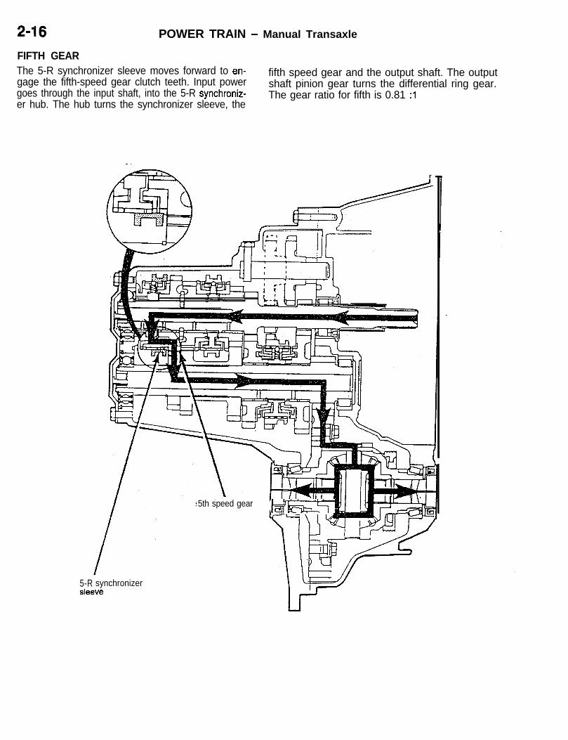
2-16 POWER TRAIN - Manual Transaxle
FIFTH GEAR
AZ=-. r
\\- I
5th speed gearJ=&EzT
The 5-R synchronizer sleeve moves forward to en-gage the fifth-speed gear clutch teeth. Input powergoes through the input shaft, into the 5-R synchroniz-er hub. The hub turns the synchronizer sleeve, the
fifth speed gear and the output shaft. The outputshaft pinion gear turns the differential ring gear.The gear ratio for fifth is 0.81 :l
5-R synchronizersleEwe
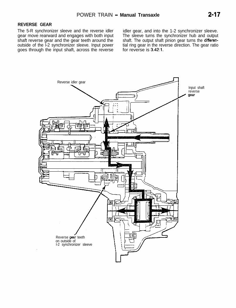
POWER TRAIN - Manual Transaxle 2-17
REVERSE GEARThe 5-R synchronizer sleeve and the reverse idler idler gear, and into the 1-2 synchronizer sleeve.gear move rearward and engages with both input The sleeve turns the synchronizer hub and outputshaft reverse gear and the gear teeth around the shaft. The output shaft pinion gear turns the differen-outside of the l-2 synchronizer sleeve. Input power tial ring gear in the reverse direction. The gear ratiogoes through the input shaft, across the reverse for reverse is 3.42:1.
Reverse idler gear
\Input shaftreverse
/ gear
Reverse gea; teethon outside ofl-2 synchronizer sleeve
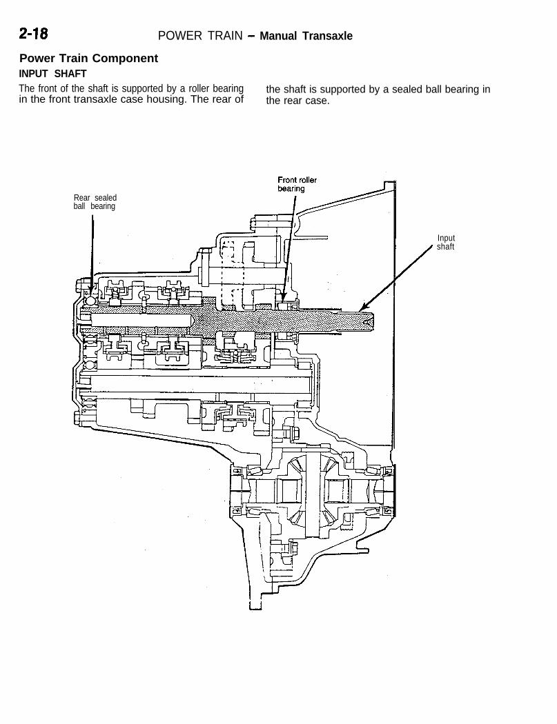
2-18 POWER TRAIN - Manual Transaxle
Power Train ComponentINPUT SHAFTThe front of the shaft is supported by a roller bearing the shaft is supported by a sealed ball bearing inin the front transaxle case housing. The rear of the rear case.
Rear sealedball bearing
I
Input
/
shaft

POWER TRAIN - Manual Transaxle 2-19Input Shaft Bearing AssemblyAn input shaft bearing assembly is pressed into the front caseof the transaxle. The assembly consists of the bearing housing,bearing, and seal. The seal prevents transmission fluid leakageinto the clutch disc area. Individual components are not service-able, if any of the components fail the entire assembly mustbe replaced. The clutch release bearing rides on the smoothround surface of the retainer during clutch operation. Greaseis not required on the retainer where the release bearing rides.

2-20 POWER TRAIN - Manual Transaxle
Input Shaft AssemblyThe input shaft transmits engine torque to the trans-axle. The assembly consists of the input shaft, 3-4
fifth speed gears, snap rings, caged needle bearingsand thrust washers.
and 5-R synchronizer assemblies, third, fourth and
3-4 sleeve 5th speed gear
1 st gear
Reverse gear
2nd\ \
5-R sleeve
geeir 3rd speed gear 4th speed gear

POWER TRAIN - Manual Transaxle 2-21
First, second and reverse gears are machined on shaft gears. The speed gears all have clutch teeth
Lthe shaft. Third, fourth and fifth speed gears ride and cones, which are used to equalize shaft speedson caged needle bearings that rotate on the shaft during shifts. The clutch teeth engage with the syn-journals. All of the forward gears are helical-type chronizer sleeves and the cones engage with thegears, and are in constant mesh with the output stop rings during a shift.
i
1. Input shaft 12. Thrust washer (2-piece)2. Third gear bearing 13. Fifth gear bearing3. Third speed gear 14. Fifth speed gear4. Third stop ring 15. Fifth stop ring5. 3-4 synchronizer 16. 5-R synchronizer6. 3-4 synchronizer snap ring 17. 5-R synchronizer snap ring7. Fourth stop ring 18. Reverse stop ring8. Fourth gear bearing 19. Reverse brake bearing race9. Fourth speed gear 20. Reverse brake bearing
10. Retaining ring 21. Reverse brake friction cone11. Anti-spin pin 22. Thrust washer

2-22 POWER TRAIN - Manual Transaxle
OUTPUT SHAFTThe front of the output shaft is supported by a roller The rear of the output shaft is supported by a sealedbearing that rides in the front transaxle case housing. ball bearing in the rear case.
\ \Il-l+7 III IIIOutput shaft
Rear sealedball bearing
Frontroller
/ bearing

l-2 sleeve
1 st speedgear \
Pinion gear
erse. .
POWER TRAIN - Manual Transaxle 2-23Output Shaft Assembly
i
The output shaft assembly transmits torque from supported by the front case. The rear of the shaftthe input shaft to the differential ring gear. The front is supported by a sealed ball bearing located inof the output shaft rides in a caged roller bearing the rear case.
gear teetn
shaft
\2nd speedgear
4th gear

POWER TRAIN - Manual Transaxle
The assembly consists of the output shaft, l-2 syn-chronizer assembly, first and second speed gears,snap rings and needle bearings. First and second-speed gears use caged needle bearings that rotateon the shaft journals. Third, fourth and fifth gears
are heated and pressed on the output shaft. Individu-al components are not serviceable because of theheat and press operations, if any of the componentsfail the entire assembly must be replaced.
1. Output shaft2. First gear bearing
9. Second gear bearing10. Inner cone
3. First speed gear 11. Outer cone4. First gear stop ring5. Outer cone
12. Second gear storing
6. Inner cone13. Second speed gear
7. l-2 synchronizer14. Third and fourth gears15. Fifth
8. l-2 synchronizer snap ringgear
16. Fifth gear snap ring

POWER TRAIN - Manual Transaxle 2-25
REVERSE IDLER
iThe reverse idler gear shaft is supported by thefront and rear cases.
Rear casesupport
Reverseidler gear
Front case/ suppofl
- - 4 I
0475-058

2-26 POWER TRAIN - Manual Transaxle
Reverse idler
Input shai 4
Reverse Idler GearThe reverse idler gear slides into mesh with the input shaftreverse gear and the gear teeth around the 1-2 synchronizersleeve. The idler gear allows the output shaft to turn in theopposite direction for reverse operation. The gear is supportedby a shaft that is held in the front and rear cases.

POWER TRAIN - Manual Transaxle
DIFFERENTIAL ASSEMBLYThe differential assembly is supported by two ta-pered roller bearings, one in the front case housingand the other in the rear case housing.
Front taperedroller bearing
/
roller bearing
Differentialassembly

2-28 POWER TRAIN - Manual Transaxle
-
Roll
Differential case
Side gear thrust
thrust washer
Pinion shaft
DifferentialThe F5MCl differential assembly is similar to previous trans-axles, except the vehicle speed sensor drive gear is mountedon the differential case. The ring gear is an open center designand is bolted to the differential case. The pinion gear of theoutput shaft is in constant mesh with the ring gear which pro-vides torque to the differential.
The differential case transfers torque from the ring gear tothe differential side gears. The differential case is mountedbetween the front and rear case housings and supported bytwo tapered roller bearings. The outer bearing races are pressedinto the front and rear transaxle case housings. The outerrace mounted in the front transaxle case uses a selectableshim behind it for differential bearing preload adjustment.
The differential allows the wheels to turn at different speedswhile the same amount of torque is applied to both. The differen-tial contains two sets of gears, the pinion gears and the sidegears. The pinions are meshed with the side gears and turnon the pinion shaft which is held in the case by a roll pin.The side gears are splined to the halfshafts and transfer torqueto the wheels. The side gear clearance must be adjusted byusing selectable side gear thrust washers.

3-4 synchronizer\ 5-R synchronizer
Input shaft
POWER TRAIN - Manual Transaxle 2-29
Synchronizer N72zco4AA
Three synchronizer assemblies are used in the 1-2 synchronizer is mounted on the output shaftF5MCl transaxle. The 3-4 and 5-R synchronizers assembly.are mounted on the input shaft assembly and the
Output shaft
Il-2 synchronizer

2-30 POWER TRAIN - Manual Transaxle
Detentball (3)
Hub Sleeve
sleeve Stop ring Speed gear
/
F&
Sleeve contktsstop ring
Gearteeth
6
SpringHub Gear cone0 .Q
Sleevecontactsgear teeth
Full gearengagement
ffG!El
Stop ring is pushedinto gear cone
@
-I
Gear
L
SYNCHRONIZER COMPONENTSThe synchronizer assemblies contain a sleeve, hub, struts,springs and detent balls. The sleeve has inner splines that slide on the hub and an outer radial slot that engages theshift fork. The hub has inner splines that engage the shaftsand outer splines that the sleeve rides on. The outer hub splineshave three slots, cut lengthwise, for the struts.
Stop rings are located between the synchronizer and the speedgears. The stop ring acts as a clutch to bring both the shaftand speed gear to the same speed, without gear clash. Duringa shift, the sleeve slides on the hub and over the stop ringto engage the gear clutch teeth. When the sleeve and thestop ring touch, they immediately begin to equalize speeds,or synchronize.
The balls are held against the sleeve by the synchronizersprings. The struts slide in the hub slots during a shift. Thesynchronizer springs use a detent ball to center the strut inthe synchronizer sleeve. Before the sleeve and stop ring contacteach other, the struts engage lugs on the stop ring, pushingthe stop ring onto the gear cone. The sleeve teeth then blockagainst the stop ring teeth until the gears synchronize. Theslots in the hub are slightly larger than the lugs on the stopring allowing the ring to turn when it contacts the gear. Theturning of the stop ring is often referred to as “clocking.”
REVERSE BRAKEA reverse brake assembly is used to stop input shaft rotationthrough a friction cone which is locked to the transaxle case.The brake is located in the rear case behind the input shaft5-R synchronizer. The brake prevents the reverse idler gearfrom clashing with the input and output shaft gears. d

POWER TRAIN - Manual Transaxle 2-31
Stop ring cone
5 FWD zz;for
The assembly looks and functions much like a synchronizer.It consists of a stop ring, friction cone, shim, needle bearingand bearing race.If a shift to reverse is attempted before the clutch completelyspins down (stops turning) the brake will stop the input shaftbefore the idler gear engages any other gear. The friction conehas lugs that fit into the case and holds the cone stationary.The 5-R synchronizer sleeve engages with the stop ring.
Shift SystemThe shift system is the link between the driver and the transaxle.The shifter assembly selects different gears by moving theshift forks. The shift system consists of the shift knob, lever,selector cable, crossover cable and transaxle shift levers.
Two transaxle shift shafts operate the shift selector assemblyinside the transaxle. A selector shaft and a crossover shaftmove the shift assembly during shifts. The selector shaft con-trols shifts into first and second, third and fourth, fifth andreverse. The arrows indicate selector shaft movement.
The crossover shaft is used to move the shift assembly fromone plane to another. The crossover shaft moves the shiftassembly from side to side allowing for shifts between secondand third, fourth and fifth. A bias spring is located around thecrossover shaft. The bias spring returns the assembly to the3-4 neutral position when the transaxle is in neutral and theshift lever is released.

2-32 POWER TRAIN - Manual Transaxle
Selectorhousing
(hT=flcnlnrtnr 4hift
,I ,,!/,II II
Select& shaft1
e t---FF-a “‘!!I’fL%;~ ;;;54t--1. 4 A l-2,IWK
1 st speedl-2 shiftfork
2nd speed
SHIFT SELECTOR ASSEMBLYThe shift selector assembly moves the appropriate shift forkbased on the drivers selection. The assembly consists of theselector, shaft, housing, and pin.
The selector housing blocks the other shift forks and preventsa shift into two gears at the same time. The selector pivotsin an arc to select the different shift forks.
A shift from fifth-to-reverse is blocked by a 5-R guide (guidesfrom 5th to 4th). The shift assembly has a pin sticking outof one side that engages the guide as it comes out of fifthgear. The guide pushes the pin and shift assembly away fromreverse gear.
SHIFT RAILS AND FORKSThe F5MCl uses three rail and fork assemblies. All of theshift forks have dual functions in that they control shifts intotwo different gears.
When the 1-2 shift fork moves to the front of the transaxle,first gear is obtained. When it moves to the rear of the transaxle,second gear is obtained.

POWER TRAIN - Manual Transaxle 2-33
5th speedSIe
When the 3-4 shift fork moves to the front of the transaxle,third gear is obtained. When it moves to the rear of the transaxle,fourth gear is obtained.
When the 5-R shift fork moves to the front of the transaxle,fifth gear is obtained. When the 5-R shift fork and the reverseshift fork move to the rear of the transaxle, reverse gear isobtained.

2-34 POWER TRAIN - Manual Transaxle
TRANSAXLE CONTROLThe shift cable and selector cable are equippedwith bushings on their transaxle ends to absorbminute vibrations from the engine and transaxle.
Also, the shift cable bracket on the shift lever enduses rubber to provides elastic support to the shift lever assembly thus minimizing vibration of the shiftlever.
<Non-turbo>Vibration-prevention rubber
cable
1Bushing
\
Shift cable andselector cable
Cable bracket
Rubber
Shift leverassembly
Cross section A-A
Vibration-preventionrubber
Shift leverbracket
Floor panel

POWER TRAIN - Automatic Transaxle 2-35
AUTOMATIC TRANSAXLEl The automatic transaxle comes in three models: 420A-DOHC and manufactured by Chrysler
F4ACl for 420A-DOHC, F4A33 and W4A33 Corporation.for 4G63-DOHC-T/C. l F4A33 and W4A33 are essentially the same
l F4ACl is electronically controlled 4-speed as the previous models.automatic transaxle newly developed for
SPECIFICATIONS
Provided (2nd to 4th)
Gear ratio(Total gear ratio)

POWER TRAIN - Automatic Transaxle
Drive system
Self-diagnosis function
Fail-safe function
Data list function
Actuator forced drive function
ATF capacity
Speedometer gear ratio
dm3(qts.)
FWD AWD
Provided
Provided
Provided
Provided
8.6 (9.1) 6.7 (7.1)
- 29136

POWER TRAIN - Automatic Transaxle 2-37
SECTIONAL VIEW
iF4ACl <FWD - 4A>
1. Damper clutch2. Torque converter3. Case4. Oil pump5. Input speed sensor6. Underdrive clutch7. Overdrive clutch8. Reverse clutch9. 2-4 clutch
10. Low/Reverse clutch11. Output speed sensor12. Planetary gear set13. Output shaft gear14. Transfer shaft15. Transfer shaft gear16. Defferential17. Input shaft

2-38 POWER TRAIN - Automatic Transaxle
F4A33 <FWD - 4AlT>
1. Damper clutch2. Torque converter
9. Transfer idler gear10. Rear cover
3. Oil pump 11.4. Front clutch
Input shaft
5. Kick-down brake12. Transfer drive gear13. End clutch
6. Rear clutch 14. Transfer shaft7. Low/Reverse brake 15. Transaxle case8. Planetary gear set 16. Differential

POWER TRAIN - Automatic Transaxle
W4A33 <AWD - 4AlT>
2 3 4 5 6
1. Damper clutch2. Torque converter3. Oil pump4. Front clutch5. Kick-down brake6. Rear clutch7. Low/Reverse brake8. Planetary gear set9. Transfer idler gear
10. Rear cover11. Input shaft
12. Transfer drive gear13. End clutch14. Transfer driven gear15. Center differential16. Viscous coupling17. Center shaft18. Front output shaft19. Front differential20. Driven bevel gear21. Drive bevel gear
11
1213
14
15

POWER TRAIN - Automatic Transaxle
CONSTRUCTION AND FUNCTION <F4ACl> N722002AA
Transaxle
r \ Sole&dI ransnllsslur Irange switch
assembly
L)
l The transaxle consists of the torque converter, l
oil pump, gear train and valve body.The gear train consists of three sets of multiple
l The torque converter incorporates the damperdisc type input clutch, two sets of multiple disc
clutch and is of the 3-element, single stage,type holding clutch and one set of Simpson
2-phase type.type planetary gear set.
OPERATING ELEMENTS IN SELECT LEVER POSITIONS
Select lever position P R N D 2 L
Speed R - 1st 2nd 3rd 4th (With OD switchturned ON) 1st 2nd 1st
Underdriveclutch 0 0 0 0 0 0
Input clutch O v e r d r i v eclutch 0 0
Reverse clutch 0
2-4 clutch 0Holding 0 0
clutch Low/Reverseclutch .* . .* . 0 0
NOTE*: Low/Reverse clutch is operated at P and N to provide smooth shift to D or R.

POWER TRAIN - Automatic Transaxle 2-41
Turbine
Solenoid Transaxle Identification
TORQUE CONVERTERTorque converter clutch operation is controlled by the TCMthrough the solenoid assembly and valve body as mentioned.The clutch lining material is not bonded to either the pistonor the torque converter cover in the F4ACl transaxle, it isfree floating.When the clutch is not engaged, pressure is directed throughthe center of the input shaft to the front side of the piston.This pressure pushes the piston rearward and allows oil toflow around the outer edge of the piston. The oil exits thetorque converter between the input shaft and the reaction shaft.
When the torque converter clutch engages, the pressure thatwas directed to the front side of the piston through the inputshaft is shut off and the circuit is vented. The pressure onthe back side of the piston pushes the piston forward andconnects the turbine to the converter housing. The piston hasno outer seal. The friction disc provides the seal between thepiston and the housing. As mentioned the friction disc is free-floating and is not bonded to either the piston or the housing.When the torque converter clutch is engaged, fuel economyis improved, engine noise is reduced, and the transaxle andfluid operating temperature is lowered.
CASEThe F4ACl transaxle uses an aluminum cast case with astamped steel oil pan. The transfer gears on the end of thetransaxle and differential assembly towards the back of thetransaxle are under stamped steel covers. This transaxle isa single sump design. That is it uses only one fluid for boththe transmission and differential areas. The transaxle caseis vented through the top of the manual shaft.

2-42 POWER TRAIN - Automatic Transaxle
CLUTCHAll flve clutches in the F4ACl transaxle are appliedhydraulically. Four of the clutches are released withbelleville springs, and one is released with a coilspring. Three of the clutches supply input powerto the planetary geartrain and are called inputclutches. The other two clutches hold componentsof the planetary geartrain and are called holding
clutches. With the exception of direct gear, one inputclutch and one holding clutch must be applied to obtain a gear range. In direct gear, two input clutchesare applied and basically connect the input andoutput shafts together. This causes the entire gear-set to rotate as one with no relative motion betweenplanetary gearset components.
C
Overdrive/Reverse Diston 1m-f-q f&drive 1
It hubu/ljjU$lerdrive~
Underdrive hub
rdrive
#3 thrust washer I
#3 thrustplate
Overdrive
Overdrive
Input Clutch AssembliesThe input clutch assembly is located directly behind the oilpump housing, and rides on the reaction shaft support journal.The assembly consists of an input shaft, input hub, clutchretainer, clutch pistons, an overdrive hub, an underdrive huband three input clutches. The clutches are the underdrive clutch,overdrive clutch and reverse clutch. When the torque converterturbine (which is splined to the input shaft) turns, the inputshaft, hub, and clutch retainer also turn.
Underdrive Clutch HubThe underdrive clutch is splined to the underdrive hub assembly.The underdrive hub and shaft assembly is splined to the rearsun gear. When the underdrive clutch is applied the rear sungear is driven (rotated).
Overdrive HubThe overdrive clutch is splined to the overdrive hub assemblyand the overdrive hub is splined to the front carrier assembly.The reverse clutch is splined to the front sun gear assemblyand rotates it when applied.
Input ClutchesEach of the three clutches, in the input clutch assembly, havethe job of supplying input power to a particular componentin the planetary gearset when they are hydraulically applied.They are connected to the planetary gearset through the over- Idrive hub and shaft assembly, the underdrive hub and assembly, and the front sun gear assembly. When any of theseclutches are applied, they turn or drive a component in theplanetary gearset.

POWER TRAIN - Automatic Transaxle 2-43Underdrive Clutch
Underdriveclutch
Rear sungear
Hub -
j Underdrive clutchhub shaft
Input clutchreiainer -
The underdrive clutch is located in the front of theinput clutch retainer. Line pressure is supplied tothe clutch from the valve body, through passages
iin the case, oil pump and reaction shaft support.The pressure then passes through a drilled passagein the input clutch hub and to the front side of theunderdrive piston. The piston moves toward therear of the transaxle, compressing the clutch andconnecting it to the underdrive hub. The underdrivehub is splined to the rear sun gear and turns itwhen the clutch is engaged.
When line pressure is released, the clutch pistonreturns with tension from the coil spring betweenthe piston and spring retainer. The piston has avent in it, and the spring retainer has a seal onit. Both the vent and retainer seal are used to keepoil on the back side of the piston. They counteractthe centrifugal pressure that develops when theclutch is spinning. Centrifugal pressure can causethe piston to move slightly and the clutch to dragwhen the clutch is not actually being applied.
Overdrive Clutch
Overdrive clutchFront planetarycarrier
/Clutch retainer
Overdriveclutch hub

2-44 POWER TRAIN - Automatic Transaxle
The overdrive clutch is the center clutch in the inputclutch assembly. The clutch pack is held on theretainer, and the piston that applies the clutch islocated around the outside of the retainer. A pressureplate in the rear of the clutch pack is used to com-press the overdrive clutch when needed. Line pres-sure from the valve body is directed through pas-sages in the case, oil pump housing and reactionshaft support. It is then directed through the inputhub and input clutch retainer to the back side of
Reverse Clutch
Hub
the OD/REV clutch piston. The pressure pushesthe piston forward and applies the overdrive clutch.The clutch pack is compressed against the samereaction plate that the underdrive clutch uses.When applied, the overdrive clutch engages andturns the overdrive hub, which is splined to the frontplanetary carrier. When line pressure to the clutchis released, the belleville spring on the front sideof the OD/REV piston returns the piston to its re-leased position.
Reverseclutch
Front sungear hub
The reverse clutch is located in the back of theinput clutch assembly. The reverse clutch is oper-ated by the same piston, pressure plate and bellevillespring that operates the overdrive clutch. Line pres-sure that applies the reverse clutch comes fromthe valve body, directed through passages in thecase, oil pump and reaction shaft support. The linepressure then goes through the input hub to thefront side of the ODFIEV piston. The pressure
moves the piston to the back and compresses thereverse clutch pack. When the clutch is applied,it turns the front sun gear and hub assembly.When line pressure to the reverse clutch is removed,the belleville spring will pull the piston forward toits released position. The OD/REV clutch pistonbelleville spring is positioned so it will counter thepiston to prevent either the overdrive or reverseclutches from dragging when they are not applied.

POWER TRAIN - Automatic Transaxle 2-45
Holding Clutches
i;2-4 Clutch
Front sungear hub
2-4 clutchI
Transaxle case /
Pistonretainer
Snao .
Bellevillespring Separator
plates
Piston Clutch’;; discs
The 2-4 clutch is one of two clutches located inthe rear portion of the transaxle case. This clutchsits behind the input clutch assembly. The 2-4 clutch/piston retainer is in the front and held in place bya snap ring. The 2-4 piston is located inside the
2-4 clutch/piston retainer. A belleville spring is usedto return the piston after releasing the clutch. Theclutch pack comes next in the case. The reactionplate is secured to the case using two snap rings.The reaction plate for the 2-4 clutch is shared withthe Low Reverse clutch. When the 2-4 clutch is
applied hydraulically, it locks or secures the frontsun gear/hub assembly to the case so it does notturn.To apply the 2-4 clutch, line pressure is sent fromthe valve body straight into the piston retainer. Thevalve body has a rubber seal located on the topof it that seals the valve body to the piston retainer.When line pressure is removed and vented, thbelleville spring returns the p’iston to release th1clutch.

2-46 POWER TRAIN - Automatic Transaxle
Low/Reverse Clutch
Front planetarycarrier
Low-reverseclutch
.
Transaxle case /
Separator PistonSnapring
plates Bellevilleretainer
spring I
Reactionplate v
Clutch Belle~lle Piston
discs snap ring
The second clutch, located in the rear of the trans-axle case, is the Low Reverse (L/R) clutch. TheUR clutch is located in the very back of the caseand, as previously mentioned, shares the reactionplate with the 2-4 clutch. Behind the reaction plateis the clutch pack, belleville spring, L/R piston, andpiston retainer. The piston retainer is secured tothe case with three screws and sealed with a gasket.
The clutch is applied with line pressure from thevalve body that is directed through the transaxlecase to the piston retainer. This pushes the pistonforward and applies the clutch. When the clutchis applied, it will lock or secure the front planetarycarrier to the transaxle case so it can not rotate.When line pressure is released, the belleville springpushes the piston back to release the clutch.

POWER TRAIN - Automatic Transaxle 2-47
POWER TRAINPlanetary Geartrain Assembly
Front sungear assembly #6 thrust #7 thrust
rear annulusassembly gear
front annulusassembly
The entire planetary gear-train is located behind theinput clutch assembly and is inside the 2-4 andUR clutch assemblies. The planetary geartrain con-
sists of two sun gears, two planetary carriers, twoannulus (ring) gears, and one output shaft.
2-4 clutch
Low-reverse
Splined to
Front Sun Gear AssemblyThe front sun gear assembly rides in the center of the frontcarrier and is welded to the center of two hubs that are arrangedback to back. Each of the hubs are splined to a clutch. Thefront most hub is splined to the reverse clutch and when appliedturns the front sun gear. The rearward hub is splined to the2-4 clutch and when applied prevents the front sun gear fromturning.
Front Carrier AssemblyThe front planetary carrier and rear annulus (ring) gear aresplined together as one unit. When the overdrive clutch isapplied, it drives the front carrier assembly by the overdrivehub. When the low/reverse clutch is applied, it holds or preventsthe front carrier assembly from rotating.
Rear Sun GearThe rear sun gear is located in the center of the rear carrierassembly. There are two thrust bearings located on either sideof the sun gear. When the underdrive clutch is applied, it drivesthe rear sun gear through the underdrive hub and shaft.

2-48 POWER TRAIN - Automatic Transaxle
outsha
I
Lugs for parkingpawl and outputspeed sensor
annulusgear
Rear Carrier AssemblyThe rear planetary carrier, front annulus (ring) gear and outputshaft are all one assembly. The rear carrier assembly is respon-sible for providing all output power for the transaxle assembly.In other words, all output from the transaxle must go throughthe rear carrier. The lugs around the outside of the assemblyhave two purposes; to engage the parking pawl when the driverselects “park”, and to generate an output speed signal usedby the TCM.There are no clutches splined or connected to this unit in anyway. The rear carrier assembly is supported to the case bytwo tapered roller bearings which must be set up with a specificpreload setting.
Planetary Geartrain PowerflowThe planetary gear-train in this transaxle providesfour forward gear ratios and one reverse gear ratio.To obtain these different gear ratios, two planetarycarrier and pinion assemblies, two sun gears andtwo annulus (ring) gears are used. Two shafts areused as input to the planetary gearset, the under-drive hub and shaft assembly, and the overdrivehub with its shaft. The underdrive shaft protrudesthrough, the center of the overdrive shaft and isthe longer of the two.To achieve any output through the components ofthis planetary gearset, the following rules apply;At least one component must be driven or turned,one component must be held stationary (kept fromrotating), two components must be driven at the
same speed and in the same direction, and all outputfrom this gearset must go through the rear carrierassembly.The planetary gear-train is driven by three input dclutches. One of the input clutches must be appliedbefore the vehicle can move. A variety of gear ratiosare accomplished by using different input clutchesto turn different components of the planetary gearset. Two clutches in the rear of the case must beused to hold specific planetary components. Whengoing through the following power flows, keep inmind that the gear-train must somehow completeits power-flow by turning the rear carrier assembly.If the output shaft/rear carrier assembly does notturn, the vehicle will not move.
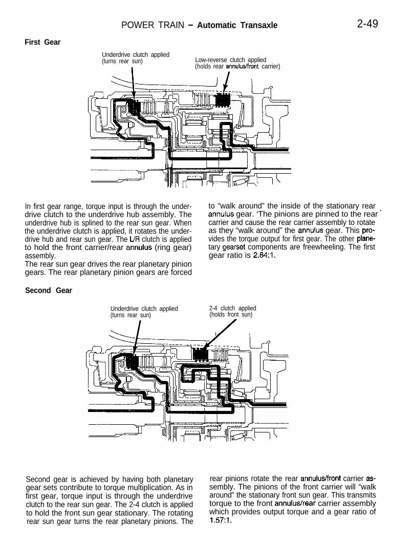
POWER TRAIN - Automatic Transaxle 2-49First Gear
Underdrive clutch applied(turns rear sun) Low-reverse clutch applied
(holds rear annulus/front carrier)
In first gear range, torque input is through the under- to “walk around” the inside of the stationary reardrive clutch to the underdrive hub assembly. The annulus gear. ‘The pinions are pinned to the rear ’underdrive hub is splined to the rear sun gear. When carrier and cause the rear carrier assembly to rotatethe underdrive clutch is applied, it rotates the under- as they “walk around” the annulus gear. This pro-drive hub and rear sun gear. The UR clutch is applied vides the torque output for first gear. The other plane-to hold the front carrier/rear annulus (ring gear) tary gearset components are freewheeling. The firstassembly. gear ratio is 2.84:1.The rear sun gear drives the rear planetary piniongears. The rear planetary pinion gears are forced
Second Gear
Underdrive clutch applied(turns rear sun)
2-4 clutch applied(holds front sun)
Second gear is achieved by having both planetary rear pinions rotate the rear annulus/front carrier as-gear sets contribute to torque multiplication. As in sembly. The pinions of the front carrier will “walkfirst gear, torque input is through the underdrive around” the stationary front sun gear. This transmitsclutch to the rear sun gear. The 2-4 clutch is applied torque to the front annulus/rear carrier assemblyto hold the front sun gear stationary. The rotating which provides output torque and a gear ratio ofrear sun gear turns the rear planetary pinions. The 1.57:1.

2-50 POWER TRAIN - Automatic Transaxle
Third Gear
Underdrive clutch applied(turns rear sun)
Overdrive clutch applied
\.(turns front carrier/rear annulus)
/
In third gear, two input clutches are applied to providetorque input; the underdrive and overdrive clutches.The underdrive clutch rotates the rear sun gear,while the overdrive clutch rotates the front carrier/rear annulus assembly. The result is two compo-
nents (rear sun gear and rear annulus gear) rotatingat the same speed and in the same direction. Thiseffectively “locks” the entire planetary gearset to-gether and is rotated as one unit. The gear ratioin third is 1:l.
Fourth Gear
Overdrive clutch applied(turns rear sun)
2-4 clutch applied(holds front sun)
In fourth gear input torque is through the overdriveclutch which drives the front carrier. The 2-4 clutchis applied to hold the front sun gear. As the overdriveclutch rotates the front carrier, it causes the pinionsof the front carrier to “walk around” the stationaryfront sun gear. This causes the front carrier pinions
to turn the front annulus/rear carrier assembly whichprovides output torque. In fourth gear, transaxleoutput speed is more than engine input speed. Thissituation is called overdrive. Fourth gear (overdrive)ratio is 0.69:1.

POWER TRAIN - Automatic Transaxle 2-51
Reverse Gear
Reverse clutch applied(turns front sun) Low-reverse clutch applied
(holds rear annulus front carrier)
In reverse, input power is through the reverse clutch. rotates the front carrier assembly pinions. The frontWhen applied, the reverse clutch drives the front carrier is being held by the UR clutch so the pinionssun gear through the overdrive hub and shaft. The are forced to rotate the Jnt annulus/rear carrierUR clutch is applied to hold the front carrier/rear assembly in the reverse direction. Output torqueannulus assembly stationary. The front sun gear is provided, in reverse, with a gear ratio of 2.21::1.
Transfer SystemThe F4ACl transaxle uses a transfer gear system to transferpower from the output shaft of the rear carrier to the transfershaft. The gear that is splined and bolted to the output shaftof the rear carrier i,s called the output shaft transfer gear. Itsupplies power to the transfer shaft transfer gear which issplined and retained by a large nut to the transfer shaft. Thebolt and nut that retain the transfer gears to each shaft mustbe tightened to the proper torque specification. Proper torqueis essential for two reasons; to keep the gears on the shaftsand to maintain the bearing settings that provide for long lifeof the system.Both gears have helical cut teeth designed for quiter operation.The overall gear ratio of the transaxle is in part determinedby the transfer gear ratio.

POWER TRAIN - Automatic Transaxle
Differential
case pinion
Final Drive Gears and DifferentialThe final drive gears include the transfer shaft which has apinion gear on one end and the differential ring gear whichis driven by the transfer shaft pinion gear. The ring gear isbolted to the differential case and when rotated drives thecase. The case drives the differential gearset and in turn, thefront axle shafts. The axle shafts then drive the front wheels.The differential gears are typical in design and include; a shaft,two pinion gears, and two side gears. The final drive gearsand the differential case each are supported by tapered rollerbearings. The transfer shaft and its tapered roller bearingsare set-up with a specific amount of endplay. The differentialring gear and case assembly bearings are set-up with a specificamount of preload. Follow the service manual procedures forsetting up these bearings to ensure long life of the bearingsand the components they support.

POWER TRAIN - Automatic Transaxle
The valve body and solenoid assembly work togeth-er to control five transaxle clutches and the torqueconverter clutch. It also directs pressurized fluidfor lubrication. The oil pump is the source of pressur-ized fluid for the valve body and solenoid assembly.The pump is a positive displacement, gear and cres-cent type pump. It is driven by the engine throughthe torque converter hub.Fluid for the pump is drawn through the transaxlefilter, through the valve body housing, and into the
Pumphousing
+ ;;rpumpReaction shafisupport
I
Seal rings (4)
VALVE BODY AND SOLENOID ASSEMBLY
pump. The pump pressurizes the fluid and sendsit back through the valve body to the regulator valve.The valve body uses only five valves along withfour solenoids in the solenoid assembly. They per-form all functions needed to operate the transaxlefor each of its gear ranges. A brief description onthe operation of each valve and solenoid follows.
Hydraulic Control SystemOIL PUMPThe oil pump is located in the pump housing inside the bellhousing of the transaxle case. The F4ACl uses a crescenttype gear pump. The inner gear is driven by the torque converterhub. Torque is supplied to the hub by the engine crankshaftthrough the flex plate and torque converter housing.As the gears rotate, the clearance between the gear teethincreases in the crescent area and creates a suction at theinlet side of the pump. Fluid is pulled through the pump inletfrom the oil pan. As the clearance between the gear teethin the crescent area decreases, it forces fluid into the pumpoutlet. The pressurized oil from the outlet operates the torqueconverter, clutches, and the lubrication system. The pump isheld in the housing by the reaction shaft support. The reactionshaft is splined to and holds the inner race of the torque convert-er stator’s overrunning clutch.

POWER TRAIN - Automatic Transaxle
Valve Body Assembly
Retainer
Q- -
Valves removedValves installed
9x-439The F4ACl has a relatively simple, cast aluminumvalve body that uses only five valves. No governorpressure or throttle pressure is used to operatethis valve body. These two pressures have beenreplaced by electronic signals from the output speedsensor and throttle position sensor. Shift valves have
and to direct fluid to the clutches, torque converter,lubrication system, and the solenoid/valves bymeans of the manual and switch valves.One side of the rooster comb (secured to top ofvalve body) operates two switches, the park neutral
also been eliminated and replaced by the solenoid/and transmission range switches. The solenoid and
valves in the solenoid assembly.pressure switch assembly is indirectly connected
The valve body has two major functions. To controlto the valve body through an extension of the case
line pressure and torque converter clutch pressurein the oil pan area.
Solenoid andpressure switchassembly
Screenfilter
Solenoid and Pressure Switch AssemblyThe solenoid and pressure switch assembly is controlled bythe TCM through the transmission control relay. The assemblyconsists of four solenoid/valve assemblies that control hydraulicpressure to four of the five clutches in the transaxle and thetorque converter clutch. A unique feature of the solenoid/valvesare that they directly control the application of a clutch. Inother electronically controlled transaxles/transmissions, theclutches are indirectly controlled by the solenoids through thenormal hydraulic valving. The solenoid assembly also containsthree pressure switches that feed information to the TCM. The“UR” pressure switch, the “2-4” pressure switch and the “OD”pressure switch. The eight-way electrical connector to the sole-noid is sealed and bolted in place with the bolt tightened toproper specification.The assembly is located outside the transaxle case, undera sound shield and protective cover, towards the front of thevehicle. The filter screen between the solenoid assembly andvalve body protects the assembly from contamination and isa replaceable item. However, if the valve body and solenoid pack have been heavily contaminated, the solenoid pack shouldbe closely inspected to determine the need for its replacement.The solenoid pack is not a serviceable unit.

POWER TRAIN - Automatic Transaxle 2-55
Torque convertercontrol valve
Overdrive clutch Solenoid
Pump (IN)
1
Regulator ValveThe regulator valve has one function, to regulate or controlhydraulic pressure in the transaxle. The pump supplies unregu-lated pressure to the regulator valve. The regulator valve con-trols or limits pump pressure. Regulated pressure is referredto as “line pressure”. The regulator valve has a spring on oneend that pushes the valve to the right. This closes a dump(vent) to lower pressure. Closing the dump will cause oil pres-sure to increase. Oil pressure on the opposite end of the valvepushes the valve to the left, opening the dump and loweringoil pressure. The result is spring tension working against oilpressure to keep or maintain the oil at specific pressures. Regu-lated pressure will vary depending on the gear range the trans-axle is operating in.A system of sleeves and ports allows the regulator valve towork at one of three different predetermined pressure levels.The oil that is dumped by the regulator valve is directed backto the intake side of the oil pump.
Torque Converter Control ValveThe main responsibility of the torque converter (T/C) controlvalve is to control hydraulic pressure applied to the front (“off”)side of the converter clutch (CC). Line pressure from the regula-tor valve is fed to the T/C control valve where it passes throughthe valve. The T/C control valve reduces or regulates the pres-sure slightly. The T/C control valve pressure is then directedto the converter clutch (CC) control valve and to the frontside of the converter clutch piston.The pressure that is being fed to the front of the piston pushesthe piston back. This disengages the converter clutch. Theoil then passes around the outside of the piston, flowing outof the torque converter and back to the T/C control valve.From the T/C control valve the oil flows to the transaxle oilcooler and cooler bypass valve. It returns to the transaxleas lube oil pressure.

2-56 POWER TRAIN - Automatic Transaxle
Regulvalve
L From manual valve
Linepressure
URclutch
4IA z/4 SolenoidDressure CLUTCH energ ized
ti
Ma&alvalve
tanusde
Solenoidede-energized
URclutch
tII
URURpressurepressureswitchswitch t
tManualvalve
tManualvalve
2/4clutch
Converter Clutch Control Valve
The CC control valve has the job of controlling the back or“on” side of the torque converter clutch. When the TCM ener- gizes the LR/CC solenoid to engage the converter clutch piston,the CC control valve and T/C control valves move to the left.The oil on the front or “off” side of the converter clutch pistonis vented to the sump.Line pressure enters the CC control valve through the manualvalve and then passes through the CC control valve and theT/C control valve to the back (“on”) side of the converter clutchpiston. Line pressure forces the piston forward which engagesthe torque converter clutch. This action effectively connectsthe torque converter turbine with the impeller. Line pressurealso flows from the regulator valve, through the T/C controlvalve, to the cooler and cooler bypass for improved fluid andtransaxle cooling.
Solenoid Switch ValveThe switch valve controls line pressure direction from the LR/CCsolenoid. When the valve is shifted to the right, it allows thelow/reverse (L/R) clutch to be pressurized. When it is shiftedto the left, it directs line pressure to the T/C and CC control dvalves to operate the T/C clutch. The valve is shifted to theright in all positions except second, third, or fourth gear. Whenthe transaxle upshifts to second gear, the valve moves to theleft which allows converter clutch engagement when needed.The valve must return to the right before a downshift to firstgear can occur.

POWER TRAIN - Automatic Transaxle 2-57
UD clutcn
valve
-Solenoidswitchvalve Vent to
mxgive
sump4 / + hh \mn,
1 Taaer / I.” “rodI I
Overdrive
~~~~~~11, 3 ?~%i~=J)
cllltnh Manual Manual-. - .-.solenok i
valve valve(de-ene rgized)
Manual ValveThe manual valve is operated by mechanical shift linkage only.Its job is to send line pressure to the appropriate hydrauliccircuits and solenoids. The valve has three operating rangesor positions. The valve is shifted to the left position when Over-drive (OD), Drive (3) or Low (L) is selected. The valve is shiftedto the middle position in both Park (P) and Neutral (N). Thevalve is moved to the right position when Reverse (R) is se-lected.
Low Reverse/Converter Clutch and Overdrive SolenoidsWhen these two solenoids are not energized by the TCM,their check balls are seated on orifices and do not allow hydraulicpressure to pass through their particular circuits. The top ofthese solenoids are tapered to allow fluid to vent to the sumpwhen de-energized. They are referred to as normally ventedvalves. When the solenoids are energized by the TCM, thecheck balls are unseated, allowing hydraulic pressure to flowpast the check ball and into the circuit. At the same time,the tapered part of the solenoid closes the vent port to thesump. This action causes full line pressure to be applied tothe desired clutch.The TCM can cycle (turn “on” and “off”) the solenoids at ahigh frequency (many times per second). This action modulatesthe element pressure between zero and line pressure. Themodulation is used when the solenoids are initially eneragizedfor more precise control of the clutches. Under certain drivingconditions, the TCM may modulate the LWCC solenoid toobtain a specific amount of T/C clutch slippage. This featureis referred to as Electronically Modulated Converter Clutch(EMCC). It allows partial converter clutch engagement, whichgives increased fuel economy and smoothes out engine pulses.
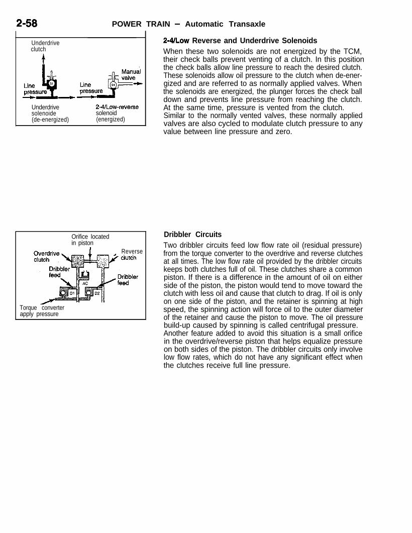
2-58 POWER TRAIN - Automatic Transaxle
Underdriveclutch
Underdrivesolenoide(de-energized)
2-4/Law-reversesolenoid(energized)
Orifice locatedin piston
Reverse- 1 . .
Torque converterapply pressure
~-~/LOW Reverse and Underdrive SolenoidsWhen these two solenoids are not energized by the TCM,their check balls prevent venting of a clutch. In this position the check balls allow line pressure to reach the desired clutch.These solenoids allow oil pressure to the clutch when de-ener-gized and are referred to as normally applied valves. Whenthe solenoids are energized, the plunger forces the check balldown and prevents line pressure from reaching the clutch.At the same time, pressure is vented from the clutch.Similar to the normally vented valves, these normally appliedvalves are also cycled to modulate clutch pressure to anyvalue between line pressure and zero.
Dribbler CircuitsTwo dribbler circuits feed low flow rate oil (residual pressure)from the torque converter to the overdrive and reverse clutchesat all times. The low flow rate oil provided by the dribbler circuitskeeps both clutches full of oil. These clutches share a commonpiston. If there is a difference in the amount of oil on eitherside of the piston, the piston would tend to move toward theclutch with less oil and cause that clutch to drag. If oil is onlyon one side of the piston, and the retainer is spinning at highspeed, the spinning action will force oil to the outer diameterof the retainer and cause the piston to move. The oil pressurebuild-up caused by spinning is called centrifugal pressure.Another feature added to avoid this situation is a small orificein the overdrive/reverse piston that helps equalize pressureon both sides of the piston. The dribbler circuits only involvelow flow rates, which do not have any significant effect whenthe clutches receive full line pressure.

POWER TRAIN - Automatic Transaxle 2-59
;. cI?
f
D2
r
Fluid ventingfrom UD clutch(through Ul orificeand thermal valve)
Cold-open
from UD clutch
Hot-closed
No pressureswitch off
With pressureswitch on
Thermal ValveThe thermal valve is a bi-metallic shutter valve that helps controlthe venting rate of oil pressure in the underdrive clutch passageduring release of the clutch. When the oil temperature is approxi-mately 20 degrees Fahrenheit or less, the valve will be fullyopen to assist in venting oil past the Ul orifice. At temperaturesabove 20 degrees, the valve starts to close and becomes fullyclosed at approximately 140 degrees, The thermal valve islocated in the transfer plate of the valve body.
Pressure SwitchesThe pressure switches in the solenoid assembly supply informa-tion to the TCM. When pressure is applied to a hydraulic circuitwhere there is a pressure switch, the switch is forced to the“on” or closed position. The switches do not tell the TCM howmuch pressure there is in a circuit, but rather that pressuredoes exist. Basically, the switches confirm to the TCM thatthe intended solenoid action did occur. They can also be usedto determine a hydraulic problem.

2-60 POWER TRAIN - Automatic Transaxle
VALVE AND SOLENOID HYDRAULIC CONTROL IN SELECTED GEAR RANGESPark/NeutralIn either of these gear selections, the transaxle haslube pressure. To provide smoother engagement,the low/reverse clutch is pressurized, anticipatinga shift to a forward or reverse gear. The LWCCsolenoid is energized which permits line pressureto the low/reverse clutch. The 2-4/LR solenoid isenergized to close off the circuit to the manual valve.
Hydraulically, this internal transaxle condition isidentical for both the Park and Neutral positions.The only mechanical difference is that the parkingpawl is engaged in the Park position.
PARK/NEUTRALSpeed under .8 mph
LR = Low reverseUD = UnderdriveR = ReverseAC = AccumulatorPT = Pressure tapS = Solenoid
24 = 2-4 clutchOD = OverdriveSW = SwitchCC = Converter CLD = DribblerV = Vent
PARK/NEUTRAL“Y . - - , - - .- , RCREV)SPEED UNDER 8 MPH
LR(p-N-‘> ?Af?-II\ I. 8, L-KL-7, “VI -7-n ODCZ-4)ccm LR=LOW REVERSE 24 =2-4 CLUTCH
1
..^ . ..^r--^...- I““=“N”tmK,YLR =REVERSE
OD =OVERDRIVESW=SWITCHCC -CONVERTER CL.
PT=PRESSURE TAP D =DRIsELER.-
.;V =VENT
LUBE . .
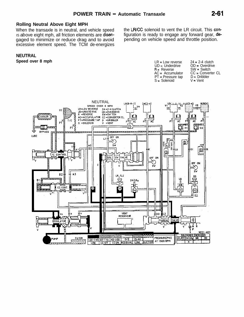
POWER TRAIN - Automatic Transaxle 2-61
Rolling Neutral Above Eight MPHWhen the transaxle is in neutral, and vehicle speed the LFUCC solenoid to vent the LR circuit. This con-
i/’ bIS a ove eight mph, all friction elements are disen- figuration is ready to engage any forward gear, de-gaged to minimize or reduce drag and to avoid pending on vehicle speed and throttle position.excessive element speed. The TCM de-energizes
NEUTRALSpeed over 8 mph LR = Low reverse
UD = UnderdriveR = ReverseAC = AccumulatorPT = Pressure tapS = Solenoid
24 = 2-4 clutchOD = OverdriveSW = SwitchCC = Converter CLD = DribblerV = Vent
NEUTRALLR(R-N- I ) 24(2-4)
SPEED OVER 8 MPHLR=LOW REVERSE 24 -2-4 CLUTCHUD=UNDERCRIVE OD =OVERDRIVE
uD( l - 2 - 3 ) O G‘(3-4) RCREV)
PRESSURE(PSI)AT(500RPM

2-62 POWER TRAIN - Automatic Transaxle
ReverseWith the manual valve moved to the reverse position,line pressure is allowed through the manual valvedirectly to the reverse clutch and also through the2-WLR solenoid to the low/reverse clutch. The regu-lator valve is designed to increase line pressurein the reverse gear range above the pressure thatis normal for other ranges. This is done to increaseclutch capacity. Line pressure is directed betweena small valve and larger valve at the right end of
the regulator valve. This neutralizes the effects ofthe larger valve on the regulator valve. With only the smaller valve working against the regulatorvalve, the regulator valve spring further closes downthe vent, causing line pressure to increase. Thereare no solenoids energized in the reverse gearrange. However, the 2-4/LR solenoid is modulatedduring initial engagement to smooththe torque tran-sition and prevent harsh engagement into reverse.
REVERSE
REVERSE LR(R-N-I) 24(2-4)B .
R=LOW REVERSED=UNDERCRIVE
24 q-4 CL”TC”
OD =OVERDRIVE-. _ .-
y t.1 AC’ACCUhULATOR CC=CONVERTERCL. _..^_ - .-
PT=PRESSutt I A,’ D =DR,SBLER
LR = Low reverseUD = UnderdriveR = ReverseAC = AccumulatorPT = Pressure tapS = Solenoid
24 = 2-4 clutchOD = OverdriveSW = SwitchCC = Converter CLD = DribblerV = Vent
RESERVOIR
PRESSURE(PSI)AT ,SOORPM
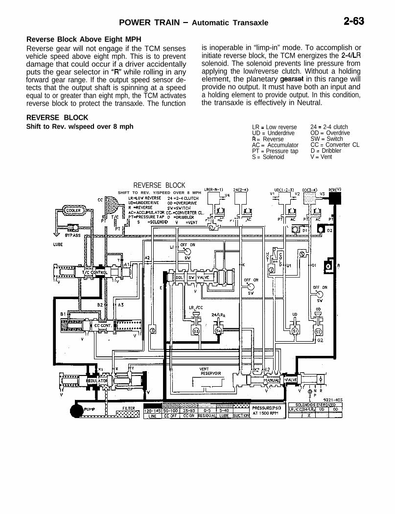
POWER TRAIN - Automatic Transaxle 2-63
Reverse Block Above Eight MPH
I/Reverse gear will not engage if the TCM sensesvehicle speed above eight mph. This is to preventdamage that could occur if a driver accidentallyputs the gear selector in “R” while rolling in anyforward gear range. If the output speed sensor de-tects that the output shaft is spinning at a speedequal to or greater than eight mph, the TCM activatesreverse block to protect the transaxle. The function
REVERSE BLOCKShift to Rev. w/speed over 8 mph
REVERSE BLOCKSHIFT TO REV. Y/SPEED OVER 8 MPH
LR(R-N-I ) 24(2-4) UD(I -2-3) OD(3-4) R
is inoperable in “limp-in” mode. To accomplish orinitiate reverse block, the TCM energizes the 2-4/LRsolenoid. The solenoid prevents line pressure fromapplying the low/reverse clutch. Without a holdingelement, the planetary gearset in this range willprovide no output. It must have both an input anda holding element to provide output. In this condition,the transaxle is effectively in Neutral.
LR = Low reverseUD = UnderdriveR = ReverseAC = AccumulatorPT = Pressure tapS = Solenoid
24 = 2-4 clutchOD = OverdriveSW = SwitchCC = Converter CLD = DribblerV = Vent
(RE
SW=SWITCHAC=ACCUMULATOR CC iCONVERTER CL.
/j PT [ ,)j S =SOLENOID v =VENT r,&,“” r’lI ’,, . . - ,,-
II
VENT, RESf;lR[ rxr&
PRESSURE(PSI)AT,500RPM

,2-64 POWER TRAIN - Automatic Transaxle
First GearWhen any of the forward gear selections are made,line pressure is directed to all four solenoids. Infirst gear the TCM will energize the LWCC and2-4/LR solenoids. This action applies the low/re-verse and underdrive clutches. The forward gearposition selected by the driver has no effect onmanual valve position. Its location will be the same
for all forward positions. The selection differenceis detected by the TCM through the transmissionrange and park/neutral position switches. Theswitches provide the TCM with the information need-ed to determine which shift pattern and scheduleto use for the selected gear range.
FIRST GEARLR = Low reverseUD = UnderdriveR = ReverseAC = AccumulatorPT = Pressure tapS = Solenoid
24 = 2-4 clutchOD = OverdriveSW = SwitchCC = Converter CLD = DribblerV = Vent
FIRST GEAR LR(R-N- 1) 24(2-41- 04 7
cc RiBALR=LOW REVERSE 24 =2-4 CLUTCH.._ ____ - .._
-4) R(REV).3) OD(
OD =OVERDRIVESW=SWITCH
OFF ON-r
UD
n
// *,
,,“1’*;y III 1; ;iov /I.,’
11. [ LRJCC II II
q 2&jk71
RESERVOIR

POWER TRAIN - Automatic Transaxle 2-65
Second Gear/
iThere are no solenoids energized in second gear. clutch engagement. When the TCM recognizes aWith the solenoids de-energized, line pressure is problem or is unable to function properly, the trans-directed to the 2-4 and underdrive clutches. Line axle goes into a default or limp-in mode. In thispressure from the 2-4 clutch circuit is also directed mode of operation, the solenoids and valve bodyto the solenoid switch valve, which moves the valve shift to a position that only provides second gearto the left. When the solenoid switch valve is moved range, regardless of any forward gear that is se-to this position, it opens a circuit that can be applied lected by the driver.by the TCM and LWCC solenoid for torque converter
SECOND GEARLR = Low reverseUD = UnderdriveR = ReverseAC = AccumulatorPT = Pressure tapS = Solenoid
24 = 2-4 clutchOD = OverdriveSW = SwitchCC = Converter CLD = DribblerV = Vent
SECOND GEAR LR(R-N-l) 24.LR=LOW REVERSE 24 =2-4 CLUTCHUD=UNDERCRIVE OD =OVERDRIVE
SW=SWlTCHAC=ACCUMULATOR CC =CONVERTER CL.PT=PRESSURE TAP D =DRIBBLER
4)
I
9AC
)FF ON
‘JD( l-2-3) OD(3-4) R(REV)

2-66 POWER TRAIN - Automatic Transaxle
Second Gear EMCCWhen conditions allow for it, the TCM pulses ormodulates the LWCC solenoid. This is called Elec-tronically Modulated Converter Clutch (EMCC), asmentioned earlier. By pulsing or modulating the sole-noid, the TCM can lower the line pressure thatpasses through the solenoid before reaching theconverter clutch and torque converter control valves.When the modulated pressure reaches the twovalves, it fully moves the T/C control valve to the
SECOND GEAREMCC
SECOND GEAR._^^Eht.staLR=LOW REVERSEUD=UNDERCRlVE
24 =2-4 CLUTCH
OD =OVERDRIVESW=SWITCH
AC=ACCUMULATOR CC =CONVERTER CL.
left, but only partially moves the CC control valve.When the T/C control valve moves, it vents thefluid from the front side of the torque converter pis-ton. At the same time, the CC control valve providesmodulated pressure to the back side of the torqueconverter piston. This condition does not cause thetorque converter piston to fully engage but insteadregulates the amount of slippage (partial engage-ment).
LR(R-N-l) 281(2-n ,,.
LR = Low reverseUD = UnderdriveR = ReverseAC = AccumulatorPT = Pressure tapS = Solenoid
24 = 2-4 clutchOD = OverdriveSW = SwitchCC = Converter CLD = DribblerV = Vent
UD(Vl
i .-I.::.
3AC p!
V
3FF ON

POWER TRAIN - Automatic Transaxle 2-67
Direct Gear (Third)To shift into direct gear, the TCM energizes the2-4/LR and overdrive solenoids. This feeds line pres-sure to the underdrive and overdrive clutches. Linepressure from the overdrive clutch circuit is directedto an area between two large plugs at the end ofthe solenoid switch valve. This keeps the solenoidswitch valve shifted to the left. The redirected linepressure from the overdrive clutch circuit allowsfor torque converter clutch engagement. It also takesthe place of second gear line pressure, that was
DIRECT GEAR
holding the valve to the left but has now been vented.The line pressure has also been reduced by usingline pressure from the same overdrive clutch circuitthat keeps the solenoid switch valve moved to theleft. Line pressure is directed to an area betweenthe regulator valve and the smaller of the two valveson the end. This aids in moving the regulator valveto the left, dumping additional oil, which results inlower line pressure.
LR = Low reverseUD = UnderdriveR = ReverseAC = AccumulatorPT = Pressure tapS = Solenoid.
24 = 2-4 clutchOD = OverdriveSW = SwitchCC = Converter CLD = DribblerV = Vent
DIRECT GEAR LR(R-N-I) 24(2-4)I “d I
UD(l -2-3) 001(3-4) R(REV)
^^ LR=LOW REVERSE 24 =2-4CLUTCH
k=AC PT AC P!P
,
I I I IIIsoLI ISW~VAI~E I I I I
E60cc

2-68 POWER TRAIN - Automatic Transaxle
Direct Gear EMCCDirect gear EMCC is accomplished the same wayas second gear EMCC. Whenever the TCM acti-
transaxle cooler to help improve transaxle cooling.
vates EMCC, it provides full line pressure from theFor a review of EMCC operation, refer to SecondGear EMCC.
ijregulator valve through the T/C control valve to the
DIRECT GEAR
LR = Low reverseUD = UnderdriveR = ReverseAC = AccumulatorPT = Pressure tapS = Solenoid
DIRECT GEARLR(R-N-1) 24(2-4) UD(l -2.
LR=LOW REVERSE 24 =2-4 CLUTCHUD=UNDERCRIVE OD =OVERDRIVE
AC=ACCUMULATOR CC =CONVERTER CL.PT=PRESSURE TAP
E
c
3
I
m
VENTRESERVOIR:I
I I ILII
-3) 00
UD
l-l
24 = 2-4 clutchOD = OverdriveSW = SwitchCC = Converter CLD = DribblerV = Vent
4) R(REV)
‘Li

POWER TRAIN - Automatic Transaxle 2-69
Direct Gear CC On
LIn direct gear, when the torque converter clutch full line pressure to the ends of the T/C and CC
is fully engaged it is called CC On. The solenoid control valves. Both the valves shift to the left. Thisand valve configuration for this position is the same allows the T/C control valve to fully vent the pressureas direct gear EMCC except the LR/CC solenoid on the front side of the torque converter piston,is fully energized instead of pulsed or modulated. causing full engagement.When the LR/CC solenoid is energized, it sends
DIRECT GEARCC ON LR = Low reverse
UD = UnderdriveR = ReverseAC = AccumulatorPT = Pressure tapS = Solenoid
24 = 2-4 clutchOD = OverdriveSW = SwitchCC = Converter CLD = DribblerU = Vent
cc
PIT/C
PT
DIRECT GEARCC ON
LR(R-N-1) 24(2-4) UD(I ,,A r-l Vl n
LR=LOW REVERSEUD=UNDERCRIVE g;:;;;g:;; L=- L J .:!-!I
R =REVERSE
S =SOLENOIDI
II I1 1r. .
AC P
UD
n
~14’HHHh
,4) R(REV)
OFF ON

2-70 POWER TRAIN - Automatic Transaxle
Overdrive Gear (Fourth)The TCM energizes the underdrive solenoid whichshuts off line pressure to the underdrive clutch. The
the 2-4 clutch to engage. This shifts the transaxle
TCM also de-energizes the 2-4 solenoid and allowsinto overdrive by allowing only the 2-4 and overdriveclutches to be applied.
OVERDRIVE
OVERDRIVE LR(R-N-I) 24- .m
m
LR = Low reverseUD = UnderdriveR = ReverseAC = AccumulatorPT = Pressure tapS = Solenoid
24 = 2-4 clutchOD = OverdriveSW = SwitchCC = Converter CLD = DribblerV = Vent
4) UO(I -2-3) 00 ,4) R(F
OFF ON
?Ebz.
.. . .
iT
OFF 1 CCON lRESlDUAL/ LUBE ISUCTION

POWER TRAIN - Automatic Transaxle
Overdrive Gear EMCCThe EMCC function is the same in Overdrive as
‘tI was in the second and direct gear positions. Fora review of EMCC operation, refer to second GearEMCC.
OVERDRIVEEMCC
OVERDRIVEEMCC ‘“=I )
LR=LOW REVERSE 24 =2-4 CLUTCH w4ccUD=UNDERCRIVE OD =OVERDRIVE LX-
1 .?‘_I-CI.,ITC”
VENT
LR = Low reverseUD = UnderdriveR = ReverseAC = AccumulatorPT = Pressure tapS = Solenoid
24 = 2-4 clutchOD = OverdriveSW = SwitchCC = Converter CLD = DribblerV = Vent
4) UD(l -2-3) OC
I
IFF ON
I?tJ:
V
,(3-.4) R
OFF ON
OD
(RI5. . ..
Y
EV)
i_ _
R

2-72 POWER TRAIN - Automatic Transaxle
Overdrive Gear CC OnIn this position the torque converter clutch is fully For a review of the transaxle operation in the CC ’engaged (CC On). The LWCC solenoid is fully ener-gized as it was in the direct gear CC on position.
on position, refer to Direct Gear CC On.
OVERDRIVECC ON LR = Low reverse
UD = UnderdriveR = ReverseAC = AccumulatorPT = Pressure tapS = Solenoid
24 = 2-4 clutchOD = OverdriveSW = SwitchCC = Converter CLD = DribblerV = Vent
OVERDRIVECC ON
LR(R-N-l) 2dr---l .
1(2-4
24 =2-4 CLUTCH
LUBE I
I) UD( l-2-3) OD
IFF ON
OFF ON
OD
PRESSURE(PS0AT 1500RPM

POWER TRAIN - Automatic Transaxle
Electronic Control SystemINTRODUCTION TO THE ELECTRONIC CONTROL SYSTEMThe advantage of using the electronic control systemis more precise control over transaxle function. Anadded advantage of the system is that it can helpthe technician find a problem in a malfunctioningtransaxle. The system can do this through whatis called On-Board Diagnostics. The TransmissionControl Module (TCM) continuously monitors its criti-cal functions during normal operation. It recordsmalfunctions in the form of diagnostic trouble codesand the number of engine starts since the last codestored in memory. The technician can use this in-formation in the event of a malfunction or complaint.Up to seven, two digit numeric diagnostic troublecodes may be stored in memory at one time.When a failure is identified by the TCM, the systemmay go into a limp-in mode by turning off the sole-noids. TCM logic is included to ensure that the limp-in event results in an orderly shut-down of transaxle
Electronic Control SystemEach of the major system components are repre-sented as a block of information. The lines betweenthe blocks represent the flow of input and outputinformation between the components.
LSome of the input and output information is uniqueto the TCM. In other words, some of the input tothe TCM is “Direct Input.” Some information (input)to the TCM is shared with other components through
function when possible. The shut-down sequencewill vary depending on which gear the transaxleis in and what the vehicle speed is at the time thefailure is identified by the TCM. This “all-solenoidsoff” limp-in mode is designed to allow for shift levermanual control of PARK, REVERSE, NEUTRAL andSECOND GEAR operation. When any forward gearshift lever position is chosen, the transaxle will re-main in second gear range.All failures do not result in limp-in, just those thatcould potentially cause internal transaxle damage.If the TCM itself fails, the transaxle will also gointo the limp-in mode.The transaxle control system consists of an electron-ic control module, called the TCM, and a systemof input and output components, that function togeth-er to control the operation of the transaxle.
the Chrysler Collision Detection (CCD) data bus.As the TCM receives input information, it continuous-ly processes it through its logic circuits in orderto perform all of the control functions that it hasbeen designed to perform. The following is a listof inputs related to the transaxle control system,both direct and indirect.

2-74 POWER TRAIN - Automatic Transaxle
Electronic control system
Brake switch
Map sensor
I Speed contr
Other vehicle-ontrol modules
Scan tool(MUT-II)
Transmissioncontrol module
control
Output speed sensorrelay
-f Input speed sensorFour solenoids
Transaxle ---a----__
Transmission range 3 pressure switchesand ParWNeutral
t
position switches
TCM Direct InputsThe direct inputs connected to the TCM are batteryfeed, ignition run signal, cranking signal, throttleposkion sensor signal, engine speed signal (distribu-tor or DE crank sensor signal), input speed sensorsignal, output speed sensor signal, transmission
TCM Indirect Inputs over the CCD BusThe indirect input signals the TCM senses fromthe powertrain control module (PCM) that are sentover the CCD data bus are, target idle speed, coolanttemperature, battery temperature, brake switch ON/OFF signal, engine speed (verifies direct input en-gine speed signal), speed control ON/OFF switchsignal, and the manifold absolute pressure sensorsignal.As stated earlier, the TCM receives input informa-tion, and it continuously processes this information
Direct Outputs from the TCMThe direct output signals or output devices the TCMhas control over are, the transmission control relay,
range switch signal, park neutral position switchsignal, low/reverse pressure switch signal, 2-4 pres-sure switch signal, and the overdrive pressure switchsignal.
through its logic circuits in order to perform all ofthe control functions that it has been designed toperform. However, some of these control functionsare internal to the TCM, while other control functionsare performed when the TCM provides some typeof output signal to another control device. The follow-ing is a list of outputs related to the transaxle controlsystem.
the four solenoids in the solenoid pack, and thevehicle speed signal.
dIndirect Outputs from the TCM over the CCD Bus
The only signal sent out from the TCM over theCCD data bus is communication with the scan tool(MUT-II) for diagnostics.

POWER TRAIN - Automatic Transaxle 2-75
Engine cranking
Scan toolcommunication
Transmissioncontrol relay
J
Transmission Control Module OperationThe main reason for having the transaxle controlledby the TCM is to have superior shift quality. TheTCM actually “learns” the characteristics of a particu-
(1) Adaptive MemoryThe TCM automatically adapts for engine perfor-mance variations and clutch torque variations toprovide consistent shift quality for the life of thetransaxle. This learning capability is called adaptivememory. If for some reason the TCM loses its
(2) Quick LearnA quick-learn procedure is available to pre-programthe shift characteristics into the TCM. The quick-learn procedure simply speeds up the TCM learningprocess. The vehicle still must be driven and shiftedseveral times in each gear range during the road
TRANSMISSION CONTROL MODULE (TCM)The Transmission Control Module (TCM), is the brain of thetransaxle. It receives information from several inputs for makingdecisions on how the transaxle should function. Some of theinformation is used only by the TCM, and some of the informa-tion is shared with other components through the CCD bus.The CCD bus is simply a communication link between theTCM and other electronic components on the vehicle.
TCM Inputs
The TCM uses various inputs to determine when to upshiftor downshift and when to engage or disengage the torqueconverter clutch. The TCM also uses these inputs for continuousfeed-back data for controlling shift quality. Without any input,the TCM has no way to determine the state of the transaxleand therefore cannot control its operation as designed. Theillustration is a list of the input sensors and signals that theTCM uses to determine control over its outputs.
TCM Outputs
In order for the TCM to perform, it must have the necessarynumber of outputs (signals or devices) that cause the transaxleto function as desired. Some of these controlled functions (oroutputs) are used by the TCM to cause upshifts or downshifts(clutch control). Other TCM outputs are information signalssent across the CCD bus to another control module. The illustra-tion provides a list of the output signals or devices controlledby the TCM.
lar transaxle to optimize vehicle shift quality usingits program logic.
memory, through a loss of battery power or thedisconnection of its 60-way connector, it takesapproximately ten shifts for the TCM to re-learnshift characteristics.
test. This will fully utilize the TCM’s adaptive memorycapability. The quick-learn procedure is accessedthrough transaxle diagnosis and performed by thescan tool (MUT-II).
2-76 POWER TRAIN - Automatic Transaxle
(3) Self DiagnosticsAnother feature of the TCM is that it helps the techni-cian find a problem within a malfunctioning transaxleor control system. It can do this through self-diagnos-tics. When something goes wrong with any of the
(4) Diagnostic Trouble CodesIn addition to sensing electrical malfunctions, theTCM can also detect some hydraulic and mechanicalmalfunctions that also produce diagnostic troublecodes. Each code represents a different malfunction.In order to read the diagnostic trouble codes, thetechnician must hook-up a special diagnostic scantool, called a scan tool (MUT-II). It will be hooked
(5) Default or Limp-In ModeAnother feature of the TCM is the ability to protectthe transaxle from potentially hazardous.operation,when certain problems arise. The TCM constantlymonitors its systems. If it senses a problem, it putsa diagnostic trouble code in memory and shuts downthe electronic controls. When this happens, it isreferred to as default or limp-in. Not all diagnostictrouble codes put the transaxle into default or limp-inmode. Only the codes that indicate a problem thatcould potentially cause further transaxle internaldamage or hazardous operation. If the TCM failsfor some reason, the transaxle automatically goesinto default.When the transaxle goes into the default mode,it automatically shifts to second gear when in anyforward gear selection and stays there. When theignition key is turned “off” and then back “on” again,the TCM resets itself to operate normally until itsenses the fault and again goes into second gear.
major electronic circuits in the TCM and/or its inputsensor and output device network, a two digit numer-ic diagnostic trouble code is put into memory.
up to a diagnostic connector, located under theinstrument panel.To retrieve diagnostic trouble codes, it is necessaryto follow the procedures outlined in the PowertrainDiagnostic Procedures manual for this transaxle.The TCM can retain up to seven diagnostic troublecodes in memory at one time.
No matter what forward gear is selected, the vehiclestays in second gear. Park, Neutral, Reverse, andSecond gear are the only gears that the transaxlewill operate in when in the limp-in mode. The ideabehind limp-in mode is to prevent the customer frombeing stranded and to provide them the ability todrive in (or limp-in) for service.As mentioned previously in the “Component Identifi-cation” section, the TCM has the job of controllingfour solenoids in the solenoid assembly. To do this,the TCM uses its programming and information fromseveral sensors. Some of the sensors are wireddirectly to the TCM and other sensor signals comefrom other electronic components across the CCDbus. The CCD bus is simply a communication linkbetween the TCM and other electronic componentson the vehicle. The communication link is madethrough two twisted wires.

POWER TRAIN - Automatic Transaxle
TRANSMISSION CONTROL MODULE INPUTS AND SENSORS
The TCM must depend on receiving information’ in order to control shift quality. Let’s take a look
Direct Battery VoltageThere is constant battery voltage supplied to theTCM, even when the ignition is turned off. Thisbattery supply is responsible for keeping the TCM’smemory alive. If the TCM loses battery voltage at
Ignition VoltageWhen the ignition switch is turned to the OFF (col-umn unlock), the RUN (on), or the Start (crank)positions, the TCM is activated and looks at incomingvoltage. If the voltage is above approximately 24volts or below eight volts, the TCM automaticallyputs itself in default. Either voltage condition coulddamage the TCM.When the TCM is activated, besides checking theincoming voltage level, it performs a self-test todetermine if the transmission control relay and thesolenoid assembly are performing as they should.
at what information it receives and how it uses thatinformation.
any time, it will lose the adaptive memory and haveto re-learn the characteristics of the transaxle foroptimum shift quality.
If the self-test results are good, the TCM sendsbattery voltage to the transmission control relay.The relay closes its internal contacts which supplybattery voltage to the TCM, the four solenoids andthe three pressure switches in the solenoid assem-bly. Whenever the TCM goes into default, it de-ener-gize the transmission control relay and preventsthe solenoids from functioning. The solenoids willthen be in de-energized positions, which cause thetransaxle to shift into second gear.
Throttle Position SensorThe F4ACl does not use throttle pressure to control shift pointslike previous transaxles did. Instead, an electronic signal fromthe Throttle Position Sensor is used by the TCM to help deter-mine shift points and shift quality.
Engine Speed SignalEngine speed is supplied to the TCM from the engine crankshaftposition sensor or distributor, depending on the engine andignition system used. This signal not only lets the TCM knowthe engine is running, but also lets the TCM calculate enginespeed to control torque converter clutch engagement, deter-mine torque capacity, etc.

POWER TRAIN - Automatic Transaxle
here I
End of the Isensor counts
torattacheshere
Park/N&tralg+j h+spe&-j 1 1 \ position switch
Input Speed SensorThe input speed sensor gives information, to the TCM, onhow fast the torque converter turbine is spinning. The sensoris located on the front side of the transaxle case, close tothe bell housing. Even though the sensor is called the inputspeed sensor, the sensor is actually generating a signal fromthe torque converter turbine through the input clutch hub. Thetorque converter turbine and input clutch hub are splined togeth-er through the input shaft. The information supplied to theTCM from the input sensor is compared to the output shaftsignal and the engine speed signal to determine planetarygearset operating ratio, torque converter clutch slippage, torqueconverter element speed ratio, torque capacity, etc. The rateof input speed change is calculated and used in controllingshifts.
Output Speed SensorThe output speed sensor is located on the same side of thetransaxle case as the input speed sensor, but much closerto the end of the transaxle. The output speed sensor generatesa signal from the rotation of the rear planetary carrier assembly.When the output speed sensor signal is received by the TCM,the signal is compared to the input speed signal to deternminegear ratio, detect clutch slippage, etc. It is also compared tothe throttie signal to determine shift points.The output speed sensor is also used as the input for calculatingvehicle speed to the Powertrain Control Module (PCM). TheF4ACl transaxle does not have a vehicle speed sensor asin other applications. The output speed signal is a direct inputto the TCM and is sent across the CCD bus for use by othercontrol modules.
‘d
Transmission Range and Park Neutral Position SwitchesThe transmission range switch is mounted to the case in thevalve body area. The input from the switch along with thepark neutral position switch tells the TCM what gear rangewas selected by the driver. The TCM uses this input to determinewhat gear range and shift pattern to use. The park neutralposition switch operates the starter relay and both the park neutral position and transmission range switches operate theback up lamp relay. The park neutral position switch doesnot allow starter engagement in any positions other than Park“P” or Neutral “N”. Both switches must be closed to operatethe back-up lamps.

POWER TRAIN - Automatic Transaxle 2-79
Solenoid and Pressure SwitchesThe low/reverse, overdrive, and 2-4 pressure switches areall located in the solenoid pack assembly. All three switchessend the same type of information to the TCM. These switchestell the TCM if there is hydraulic pressure in their particularcircuits. The pressure switches do not tell the TCM how muchpressure is in the circuit. They just indicate that pressure existsor does not exist. This information verifies that the solenoidsare operating correctly and what gear the transaxle is in. Theswitches open at approximately 11 psi and close at approximate-ly 23 psi.
Engine Coolant Temperature SensorThis engine coolant temperature sensor tells the TCM the tem-perature of the engine. When the engine is cold, the TCMmay delay upshifts slightly to improve vehicle driveability. TheTCM prevents the torque converter clutch from engaging untilthe engine warms up to normal operating temperature. If theengine temperature is too high in any forward position, theTCM engages the torque converter clutch in second, third,or fourth gears to help cool the engine and prevent the transaxlefrom overheating.
Brake SwitchThe brake switch signal is used to make sure the torque convert-er clutch is disengaged when the brakes are applied. It isalso used to cancel cruise control so that braking can occur.

2-80 POWER TRAIN - Automatic Transaxle
Engine SpeedThe TCM uses both direct engine speed input from the crank-shaft position sensor or distributor and calculated engine speedinput from the PCM over the CCD bus. The direct input isrequired to provide immediate information for use by the TCMcontrol logic. The slower CCD engine speed data is used bythe TCM fail-safe logic to confirm that the direct engine speeddata is valid.Speed Control SwitchThe speed control on/off switch modifies the shift pattern whena speed control “on” signal is received by allowing a torqueconverter clutch engagement or disengagement, as well askickdown shifts.
Manifold Absolute Pressure Sensor (MAP)The MAP sensor provides engine load input and output torqueload on the input shaft to the TCM. These signals are sentacross the CCD bus to the TCM. The TCM uses this informationto modify shifting and reduce 3-4 shift hunting on grades. d

POWER TRAIN - Automatic Transaxle 2-81
TRANSMISSION CONTROL MODULE OUTPUT SIGNALS AND DEVICESThe TCM takes the input information from the sen- sembly. The following items are output componentssors, evaluates the input, then uses it to control operated by the TCM.the transmission control relay and the solenoid as-
Transmission Control Relay
Solenoid and pressure
The instant the ignition is turned on, the TCM performs a self-testto determine if its internal electronic circuits are all workingproperly. If the self-test results are good, the TCM sends batteryvoltage to the transmission control relay. The relay closes itsinternal contacts which then supply battery voltage to the TCM(confirms function of the relay), the four solenoids and thethree pressure switches in the solenoid assembly. If the TCM“sees” a problem in the system, it turns off the power feedto the transmission control relay, causing the contacts to open.A diagnostic trouble code is then stored in memory. The trans-mission control relay is located in various places dependingon the vehicle model. It can be located directly on the TCMor in the harness near the TCM.
Solenoid AssemblyWhen the transmission control relay contact points are closed,the solenoid assembly receives electrical power. The TCMcan now operate the solenoids, as determined by its program-ming. The relay provides power to all four solenoids througha single wire. This means that all the solenoids have voltagesupplied to them whenever the transmission control relay isclosed. The solenoids, however, are not energized until theTCM grounds the solenoid return wire for the solenoid thatis needed.Power and GroundThe ground wire from each solenoid goes back to the TCM.The TCM energlizes each solenoid by connecting the solenoidreturn wire to ground. Four of the wires in the 8-way solenoidassembly connector are solenoid return wires. Three wiresare for each pressure switch, and the last wire is the batteryfeed wire from the transmission control relay. The TCM controlsboth the power feed (through the transmission control relay)and the ground to each solenoid (through the return wires).

2-82 POWER TRAIN - Automatic Transaxle
Vehicle Speed Signal
The vehicle speed signal is sent as a direct inputfrom the TCM to the PCM. This system is calledelectronic pinion. The output speed sensor signalis sent to the TCM and used as the vehicle speedsignal. The F4ACl does not use a vehicle speedsensor as in past transaxles. The TCM convertsthe output speed sensor signal to an 8000 pulse-per-
Scan Tool (MUT-II) InterfaceThe TCM and other components have the abilityto interface (“talk” to each other) over the CCD bus.The scan tool (MUT-II) connects to a data link con-nector located in the passenger compartment. This
mile signal. The signal is then sent directly to thePCM.Using the transaxle output speed sensor for thevehicle speed signal has resulted in reducedmanufacturing process time, cost savings, increasedreliability, and increased speedometer accuracy.
allows communication with the TCM on the CCDbus. Refer to the F4ACI Transaxle Powertrain Diag-nostic Procedures manual for the data link connectlocation.

POWER TRAIN - Automatic Transaxle 2-83
TRANSMISSION CONTROL MODULE OPERATION: Introduction
What does it do and how does it know? You haveprobably asked yourself this question more thanonce as you pondered some transaxle problems.This is really a very complex question. Just stopand think about it for a minute. Think of all theelectronic logic features that have to be programmedinto this small control module so that it will alwaysknow just what clutch to apply and release, at justthe right time, under all the different driving condi-tions that could possibly take place.A description of the TCM’s electronic functions canbe simplified if we look at them, one main logicfunction at a time. We will use this “logic function”approach to describe in simple terms how the TCMmakes some of these complex decisions. We will
TCM Routine and Logic FunctionsMany of the control logic functions discussed inthis section rely on output information from a priorlogic function as their main input information. Thisshould be kept in mind when you are doing yourdiagnosis. Most of these logic functions are recalcu-lated and updated on a regular basis and in a specific
/ Start Routine
The first function the TCM performs, when the igni-tion key is turned on, is the Start Routine. Thisroutine allows the TCM to check critical inputs andmemory circuits before it powers-up the system.If everything is ok up to and including the switchedbattery tests to the TCM and pressure switches,then the TCM will power-up the transmission controlrelay and finish the remaining checks as describedbelow.The Start Routine is performed when the ighitionswitch is turned to the OFF (column unlock) or RUNpositions and again when the ignition switch is re-turned to the run position after engine cranking.
concentrate on the main logic functions and definethe primary input and output requirements. By doingthis we will be able to use simple block diagrams,charts and graphs to illustrate how some of thedecisions are made. We will not cover electronicallyhow the actual logic circuits inside the TCM work.The main logic functions, covered in this lesson,include the Start Routine, Transmission Range andPark Neutral Position Switch Logic, Shift Lever Posi-tion Logic, Speed Sensor Logic, Transaxle Tempera-ture, Shift Schedule Logic, Torque Converter EMCCLogic, Shift Selection Logic, Shift Execution Logic,Solenoid Switch Valve Control Logic, Clutch ApplyStatus (Clutch Volume Tracking), Normal ShutdownRoutine, Fail-Safe Routine.
sequence. This sequence and the time interval thatit takes to complete these normal functions is re-ferred to as a program loop. A program loop occursonce every 7 milliseconds (.007 seconds). Somespecial checks or logic functions may be performedmore or less frequently.
NOTEThe ignition switch has been redesigned to allowfor power up of the TCM, BCM and electronicPRND2L display. This occurs with the key in thecolumn unlock position, just before the ignition runposition.Any invalid result sets the appropriate diagnostictrouble code, and the system immediately goes intolimp-in. The TCM identifies the crank period by thecrank signal input provided at pin 8. When the cranksignal is present, the TCM is stopped and is re-initial-ized after cranking to eliminate the possibility oflow cranking voltages or spikes confusing the Cen-tral Processing Unit (CPU). The CPU is a smallmicroprocessor inside the TCM that contains thou-sands of transistors and diodes on a chip of siliconesmall enough to fit on the tip of your finger.

POWER TRAIN - Automatic Transaxle
Random Access Memory (RAM)One of the start routine checks is to verify that thedata storage bits in each RAM location are function-ing properly. RAM is a form of memory that can
Read Only Memory (ROM)A ROM check also occurs during the start routine.The check is to verffy that all of the data storedin the ROM is valid. ROM is a permanent memory
be written to and changed, as well as read from.Code 17 is reported with a failure of RAM.
in the TCM and is used to store the programs neededto run the system. Code 16 is reported with a failureof ROM.
Transmission Control Relay and Driver Circuit Continuity Checks
Prior to power-up, the relay contacts should notbe passing current (relay open). Code 14 is reported
for each solenoid. Codes 41 through 44 are reported
with a failure of the transmission control relay con-with a failure of any one solenoid.
tacts (stuck closed).After completion of the Start Routine, all of the nec-
All three pressure switch inputs should be in a power-essary control logic variables are reset prior to acti-
off condition. Code 20 is reported with a failurevating the main control program. Some of the vari-
of any pressure switch (switch closed, indicatingables that require resetting are clutch volume track-
pressure when none exists).ing values set to zero, initial speed values are calcu-
With the above checks all valid, the TCM then closeslated, various counters and timers are cleared, and
the relay and verifies that the relay contacts areshift logic selection is set to neutral.
passing current. Code 15 is reported if this failsFor the first few seconds of main program execution
(relay contacts never close).following start up, the pressure switch checks are
With the transmission control relay contacts closed,not performed. This allows time for the transaxle
the TCM then confirms the driver circuit continuityoil pump to develop pressure and purge the airfrom the various hydraulic circuits.
Park/Neutral Position and Transmission Range Switch Logic
This logic function reads the switch positions ofthe transmission range and park neutral positionswitches on the manual lever (rooster comb) to de-termine the driver-selected operating mode.The primary input for shift lever position to the TCMcomes from the transmission range and park neutralposition switches. The logic in the TCM for theseswitches reads the four bit code determined by theswitch positions. When closed, each switch providesground for the particular circuit it is in (TI, T3, T41,T42). The status of these switches is based onshift lever, manual valve and rooster comb positionswhich determines the logic output code.
Reverse, N = Neutral, D = Drive, 2 = Second, andL = Low. There are also some transition codes thatoccur between switch positions that are recognizedby the TCM. They are Tl, T2, and T3. An I codealso exists as an invalid code.These logic output codes are then used by the ShiftLever Position (SLP) logic in the TCM.NOTEThe scan tool (MUT-II) does not recognize the differ-ence between transition and invalid codes. A “?”on the display screen, of the scan tool (MUT-II),is used to represent these codes when they arepresent. They can occur between shift lever posi-tions. F4ACl Transaxle ElectronicsThe output signal may be any of the following, de-
pending on the logic output code. P= Park, R =

POWER TRAIN - Automatic Transaxle
SLP T42 T41 TO1 TO3
P CL CL OP OPR OP OP CL CLN OP CL CL OPD OP OP OP CL2 OP OP CL OPL CL OP OP OP
Tl OP CL OP OPT2 OP OP OP OP
Shift Lever Position output becomes the “PRND2L”input to most of the other functions.The R, P, N, Tl and ‘73” PRND2L codes are alwaysaccepted by the SLP logic as being valid and arealways converted directly to R, N or “D” SLP codes.This is done because these codes can only occurwhen the corresponding Reverse, Neutral or Drivemanual valve porting is established. This improvesthe response time necessary for garage shifts (Re-verse - Neutral - ‘ID”).SLP output with 2, L, T2 and Tl codes is basedonthe current SLP position as well as current pres-sure switch and speed ratio data. The pressureswitch and speed ratio data are monitored to identifywhich hydraulic mode of operation exists (reverse,neutral or drive) so that the appropriate selectionis made for Shift Lever Position.NOTETo help clarify the SLP table, keep in mind thatSLP logic only uses N because transmission controlOn some vehicles it may be possible to cause pres-sure switch or speed check diagnostic trouble codes
Speed Sensor Logic
Speed and acceleration calculations provide criticalinput information to the logic functions within theTCM. Speed sensor logic determines gear selection,shift timing and shift quality. This information is usedas input to the shift schedule, shift logic selectionand shift logic execution functions, programmed intothe TCM.There are four important input values that mustbe calculated; engine speed, input speed, input ac-celeration, and output speed.The TCM receives a direct engine speed signalfrom the crankshaft position sensor or distributordepending on the vehicle and engine used. Enginespeed is calculated and updated with each sensorpulse. The TCM also receives an engine speedsignal from the PCM over the CCD bus. Immediatedirect input of engine speed is needed for propertransaxle operation. It cannot be provided by theengine speed signal from the PCM over the bus.However, both “engine run” signals allow the TCM
Shift Lever Position (SLP) LogicThe primary function of SLP logic is to provide safe, continuous,but limited operation of the transaxle with the presence ofan invalid or transition input code. The SLP logic functionscreens the input codes from the switches and provides anSLP output signal to control actual gear selection.Inputs include the codes indicated by the transmission rangeand park neutral position switches, current shift lever position,pressure switch indications, and speed ratio data from theinput and output speed sensors.
module logic is identical in Park and Neutral (samehydraulic porting).NOTEAn incorrect input (for example, a defective switch)of one of these positions could, with sufficient time,result in either a pressure switch or speed checkfault, when in fact the real cause is a transmissionrange or park neutral position switch error. Thistype of fault can occur, for example, when the manualvalve porting is in reverse but the code is indicating“D”. In this case, the low/reverse pressure switchdata and input speed data will not agree with theexpected results for Shift Lever Position = 73”.NOTEIt is extremely important that accurate shift leverposition data be available to the TCM. The accuracyof any diagnostic trouble code found in memoryis doubtful unless the Shift Lever Test, performedon the scan tool (MUT-II), passes without fail.
by holding the shift lever mid-way between ‘ID” andNeutral.
to distinguish between a failure of the crankshaftposition sensor or distributor pulse input throughthe circuits versus an actual engine stall or keyon engine off condition.Input speed data from the input speed sensor iscalculated by the TCM. The data is based on thenumber of teeth and time between each tooth sincethe last main program loop. Input acceleration iscalculated from the change in torque converter inputspeed over time.Output shaft speed data from the output speed sen-sor is calculated based on the number of teeth andthe time between each tooth since the last mainprogram loop.Speed information is also used to verify that steadystate in-gear operation is normal. Output shaft speedtimes current gear ratio is continually checkedagainst input speed in order to identify the occur-rence of an input or output speed sensor failureor a clutch that is slipping.

POWER TRAIN - Automatic Transaxle
Transaxle TemperatureThe transaxle temperature operating range is basedona predicted fluid temperature which is calculatedfrom a combination of inputs. The predicted fluidtemperature is continually updated and retained inmemory for 20 minutes after the ignition switch isturned off. When the vehicle is started after an ex-tended off time, the predicted fluid temperature isreinitialized at a value equal to the battery tempera-ture signal received from the PCM over the CCDbus. The temperature input signal must then be
Transaxle Temperature Output ModesOutput modes used by the TCM are extreme cold,supercold, cold, warm or hot. The extreme coldrange is set when the initial predicted fluid tempera-ture is less than - 15 degrees F. It will clear twominutes after a cold start. The supercold range isset when the predicted fluid temperature is lessthan 0 degrees F. It will clear when the predictedfluid temperature exceeds 10 degrees F. The super-
Shift Schedule LogicShift schedule logic, programmed into the TCM,selects the appropriate shift schedules for the cur-rent operating conditions. This is to determine the“desired” gear range the transaxle must be operatedin. The desired gear range is a primary input tothe shift logic selection function. The TCM then acti-vates the appropriate shift logic schedule to achievethe desired gear. The actual shift points within eachshift schedule have been pre-determined for besttransaxle operation and are stored in the TCM’sROM memory.
calculated and then increased primarily based ontransaxle run time in gear. Time calculation excludesoperation in park and neutral.A detailed explanation of how transaxle temperaturerange affects transaxle operating characteristics iscovered in the shift schedule and EMCC sections.The primary temperature inputs to the TCM arebattery temperature, engine coolant temperatureand in-gear run time since start-up.
cold range allows for near normal transaxle opera-tion under sub-zero conditions. The cold, warm,and hot ranges provide different operating featuresas warm-up occurs. The transaxle temperaturerange is “cold” at less than 36 degrees F, “warm”above 40 degrees F and “hot” above 80 degreesF.
The primary inputs to the TCM are the transmissionrange and park neutral position switches (shift leverposition), throttle position, and output speed. Someother secondary inputs include, but are not limitedto, calculated transaxle temperature and currentshift logic.Shift schedule output codes simply provide the TCMwith the desired operating gear range signal. Shiftschedule logic output is updated every 7 millisec-onds and is a primary input to the Shift Logic Selec-tion function programmed into the TCM.
POWER TRAIN - Automatic Transaxle
Inhibits and Shift Action Summary
For neutral (N) and reverse (R) there are no logicinhibits placed on SLP changes into or out of eitherneutral or reverse. These gear ranges are shift levercontrolled modes of operation. Neutral and reversemust be immediately provided for. Also, a reverseblock function is used at speeds over approximately10 - 15 mph by continuously venting the Low/Re-verse (L/R) clutch. The L/R clutch is also ventedat speeds over 8 mph in neutral.For drive (D), Second (2) or low (L), when speedratio or pressure switch errors occur during transaxleuse, the TCM will maintain the current gear rangeto prevent potentially hazardous gear selection.A separate set of shift schedules exist for eachengine/transaxle application. The TCM knows whichset of shift schedules to use by looking at the PCMidentiftcation over the CCD bus. The engine and
SLP = “D” Cold, Warm or HotThe “D” schedule provides first, second, third andfourth gears. This shift schedule is selected whenSLP = “D” and the transaxle calculated temperaturerange is cold, warm or hot. It should be noted thatthe “D” schedule will delay the 3-4 upshift, and will
body identifications are retained in the TCM’smemory to ensure that the correct schedule is usedif the CCD bus fails.There are four different shift schedules within eachengine set. They are selected primarily by the ShiftLever Position input code and the transaxle operat-ing temperature range that is calculated. Separateshift schedules exist for the following; Shift LeverPosition = D, Shift Lever Position = D (supercoldtemperature range), and Shift Lever Position = L.A typical set of shift schedules have been plottedout in graph form. These have been modified ‘forclarity. The shift schedules primarily use throttleangle and output shaft speed as the determiningfactors. The main difference between these sched-ules are as follows:
cause earlier 4-3 downshifts when the transaxletemperature range is cold. Throttle input is alsolimited to prevent high engine speeds with a coldengine.
SLP = “D” (Supercold and Extreme Temperature Range)IThe supercold “D” schedule is a revised D schedule.It is selected whenever the initial calculated trans-axle temperature is less than 0 degrees F. Thisrevised schedule prevents closely spaced shifts andpart throttle kickdowns. This results in delayed (high-er speed) upshifts, earlier closed throttle downshifts,and in most cases the inability to obtain either 4-2or 3-1 kickdowns. The primary reason is to allowmore time for clutch pressures to achieve their nor-mal in-gear condition after a shift. This should hap-pen before the next shift occurs to avoid clutchoverlap (two clutches applied at the same time).
If the calculated transaxle temperature at start-upis in the extreme cold range of - 15 degrees F.or less, all the solenoids will be held off. Also, thepressure switch and speed sensor checks will ,bedisabled. This action provides the same mode ofoperation as with limp-in or default (second gearoperation only, in any forward gear range selection).This is done to prevent clutch damage and inadver-tent shutdowns by delaying all TCM operation untilsupercold conditions can be met.
SLP = L
The L schedule also has 1-2 and 2-3 shifts butthey are much more delayed. The determining factorfor this schedule is that engine speed is monitoredand shifts occur at peak engine RPM. Even thoughthe driver has selected the low position, the shiftschedule is designed to upshift the transaxle at up-
per level engine RPM to protect the engine fromover-speed. Downshifts also occur at higher vehiclespeeds. This is done to provide the highest gearratio for maximum engine braking when descendingsteep grades.

POWER TRAIN - Automatic Transaxle
Adaptive Coast Down SchedulingAdaptive scheduling may result in delayed 4-3 or3-2 downshifts under certain conditions in order
Speed ControlWhen the transmission temperature range is eitherwarm or hot, the 4-3 shift pattern is modified tokickdown earlier if a cruise control “on” signal isreceived over the CCD bus from the PCM. If the
Manifold Absolute Pressure (MAP)This signal is used to calculate changes in engineoutput torque to the input shaft of the transaxle.This information is used by the TCM to improve
Throttle FailureA throttle default value of 25 degrees throttle openingis substituted to provide reasonable driveability.Third gear is substituted for fourth to provide a toler-
CCD Bus FailureThe initial predicted fluid temperature is based onthe battery temperature after an extended time off.It is important to understand that if this data becomesinvalid (out of normal range or the CCD bus fails),the TCM will substitute -3 degrees F. for ambienttemperature. This is done because the control logicfor the colder temperature range is designed totolerate an actual warmer transaxle. Some of the
Loss of Prime ProtectionSpecial logic is included in the fail safe routinesto identify a loss of oil pump prime. A no pressurecondition is usually due to a low fluid level andtypically occurs following hard braking or cornering.This will cause the oil filter to be exposed to air.
II I1 %g’ 1-1 $!& .
to maintain good shift quality.
bus should fail, this logic will not be initiated withspeed control “on”, and the vehicle may lose morespeed and not kick down on grades.
shift quality and reduce 3-4 shift hunting on steeperroad grades. A loss of this signal will cancel gradehunting detection logic.
able performance level. Throttle induced kickdownswill become unavailable, but selection of drive andlow shift lever operation remains normal.
effects of this are as follows; Defaults are possibleif the actual transaxle temperature is within the ex-treme cold range. The 3-4 shift will occur at a higherspeed for approximately the first minute of operationin-gear (see supercold “OD” shift schedule). A reduc-tion in upshift shift quality is possible for approxi-mately 4 minutes if the actual transaxle temperatureis in the warm to hot range.
The result will be a loss of oil pump prime andpossibly a no drive condition. The special logic pre-vents the inappropriate setting of diagnostic troublecode.
Torque Converter EMCC LogicThe use of partial Electronically Modulated ConverterClutch (EMCC) is available at speeds as low as 17mph, giving the advantage of improved fuel economywhile buffering the rest of the power-train from enginefiring pulses. Full EMCC is utilized under certainconditions to improve gas mileage. Both full EMCCor partial EMCC may also be scheduled to help reduceheat build-up of the transaxle or its fluid under certaindriving conditions.Torque converter full EMCC and partial EMCC avail-ability depends on many different input conditions.These include shift lever position (D, 2, L), currentgear range (second, third, or fourth), engine coolanttemperature, input speed, and throttle angle.The outputs controlling the torque converter are; No’dEMCC, Partial EMCC, Full EMCC and Gradual toNo EMCC. The boxes in the chart represent thefour EMCC logic states.
\

POWER TRAIN - Automatic Transaxle
Types of EMCC Logic
LNo EMCC Logic -This is when the torque converterclutch is off.Partial EMCC Logic - This logic will modulate theLB/CC solenoid (duty-cycle) to obtain partial torqueconverter clutch application. Partial EMCC operationFull EMCC Logic - This increases the LR/CC sole-noid duty-cycle to full “on”, after partial EMCC controlbrings the engine speed to within the desired slipGradual to No EMCC from Full or Partial Logic -This logic is designed to soften the change fromFull or Partial EMCC to No EMCC, at mid-throttle,
EMCC Fail-safeA malfunction of the EMCC system is detected froma lengthy partial EMCC operation near the maximumallowable duty-cycle, except at heavy throttle. If adiagnostic trouble code is reported, the TCM will
EMCC Break-in ProcedureWith the vehicles odometer reading from 0 to 500miles, there will be no torque converter EMCC. From500 to 1500 miles, the TCM will gradually decreaseEMCC from a 200 rpm slip to a 60 rpm slip. Whenvehicle mileage is above the EMCC break-in period
idand a malfunction occurs with the torque converter,
EMCC InhibitsThe TCM is provided with EMCC inhibits to preventEMCC from occurring under specific conditions. Thefollowing are times when EMCC will not occur.Transaxle Temperature - When the transaxle tem-perature range is cold or supercold, EMCC is inhib-ited (kept from occurring). In the event of a CCDBus failure, -3 degrees F. is substituted for the initialBrake Signal (on) - This will cancel and preventEMCC as long as a brake signal is “on”. If a busfailure occurs, the “brake on” signal is not received,and EMCC is still possible.Solenoid Switch Valve - If a solenoid switch valve(SSV) malfunction is detected, EMCC will not occur.A SSV diagnostic trouble code will only be storedEMCC Fault - Any reported EMCC diagnostictrouble code will prevent any type of EMCC fromoccurring.
is maintained until full EMCC logic is called for andactuated.
range of transaxle input speed relative to enginerpm (crankshaft speed).
by gradually decreasing the LFUCC solenoid duty-cycle.
not operate the torque converter clutch. It will remainunapplied until the next restart. Diagnostic troublecode 38 will be stored in memory.
the new replacement torque converter must gothrough the same EMCC break-in procedure. TheTCM must be re-programmed to allow for (restart)the break-in period. To do this, use the scan tool(MUT-II).
temperature. This initial value is incremented upto normal engine operating temperature based onengine running time. This will result in delayedEMCC operation under start-up conditions.Throttle Position Sensor - Any throttle value lessthan 2 or 3 degrees (closed throttle) will cancelEMCC. If a throttle position sensor failure is identifiedby the TCM, EMCC will not occur.if the transaxle operating temperature range is hot,and the malfunction occurs at least three times.The fault counter is reset during the start routine.
i

2-90 POWER TRAIN - Automatic Transaxle
2s 2ND
I
1ST 1s
q = In-gear logic
n = Shift logic
1 S, 2s = Shift schedule output1 ST, 2ND = Speed ratio shift
complete signal
Shift Logic SelectionThe purpose of the Shift Logic Selection program is to activatethe appropriate “shift logic” so that the “in-gear logic” conditionmatches the gear called for by the shift schedule (driver selectedgear, throttle position).Imagine that the TCM must always be in one of the logic boxesat any given time. The double line boxes represent the “in-gearlogic” the TCM uses to maintain a certain gear range. Thesingle line boxes represent the “shift logic” required by theTCM to execute a desired gear change from one gear to another.The paths (lines with arrows) between the blocks are labeledwith one or more of the shift schedule output signals (Is, 2s).These desired gear signals (shift schedule output signals) be-come the primary input which will cause the correct path tobe taken, from one in-gear box (such as inl) to a shift logicbox (such as l-2).The output is a change to “shift logic” in order to obtain anin-gear conditon that matches the output of the shift scheduleroutine. The TCM knows whether the desired shift has beencompleted when a correct speed ratio check of the input andoutput speed sensors is present. The speed ratio check isused to verify that the desired gear has been achieved. Forexample, when the correct speed ratio signal for second gearhas been verilied by the TCM by checking the speed ratiobetween the input and output speed sensors, it will switchto the appropriate in-gear logic (in2).
Changes to “In Gear” or “Shift” LogicIf the transaxle is in first gear logic (inl) and theshift schedule output changes to call for secondgear (2s), then “1-2” logic will be activated. Thisgenerally remains in effect until the completion ofthe shift is determined by the speed ratio check.When the speed ratio check confirms that the de-gired gear (second) has been obtained, ‘in2” logicis activated. There are other possible exits orchanges that may be made to the normal shift sched-ule logic from the “1-2” shift logic example, suchas a change-mind condition.A “change-mind” shift condition may occur whena shift that has begun directly from within another
Shift Logic ChartAnother exit or change to the normal shift schedulelogic is the fail shift timer may expire. The TCMwill only allow a certain amount of time to elapsefor the shift logic to complete a shift. If a speed
shift, instead of from an in-gear condition. A “changemind” condition occurs if a change in the throttleposition signal causes the normal shift scheduleroutine to select a different desired gear signal, suchas is, during a 1-2 shift change. These shifts areaccommodated by direct paths between upshift anddownshift logic within the logic selection routine.“Change mind” shifts are needed to provide theproper response to changes in driver demand.Changes in the manual lever (selector lever) positionmay also cause a “change-mind” shift dependingon when the lever position changes. A more detailedshift logic chart is illustrated.
ratio check does not confirm the completion of anattempted shift within this time limit, the shift logicis aborted, and the desired in gear logic is activated.

POWER TRAIN - Automatic Transaxle
101 = In-gear logic
q = Shift logic
Shift Execution Logic
1 ‘121 )9( 421
1 S, 2S, 3S, 4S, RS = Shift schedule outputlst, 2nd 3rd, 4th, Rev. = Speed ratio shift
complete signal
L
As with most automatic transmissions, including theF4ACl gearset, two clutches must be applied toprovide an operating gear range. One of the appliedclutches must be an input clutch driven by the torqueconverter, such as the Reverse, the Underdrive,or the Overdrive clutches. The other applied clutchis usually a reaction or holding device, such as
the 2-4 or L/R clutches. For all gear ratios this isthe rule, except Direct Drive (3) where output isachieved by applying two input clutches. All shiftsleave one clutch continuously engaged and involvechanging another clutch from the releasing clutchto a different applying clutch.
cc
Gear Ratio Clutchesapplied
ReverseNeutralFirstSecondDirectOverdrive
2.21 R, LR
2.64 UFLR1.57 UD; 241 .oo UD, OD0.69 24, OD
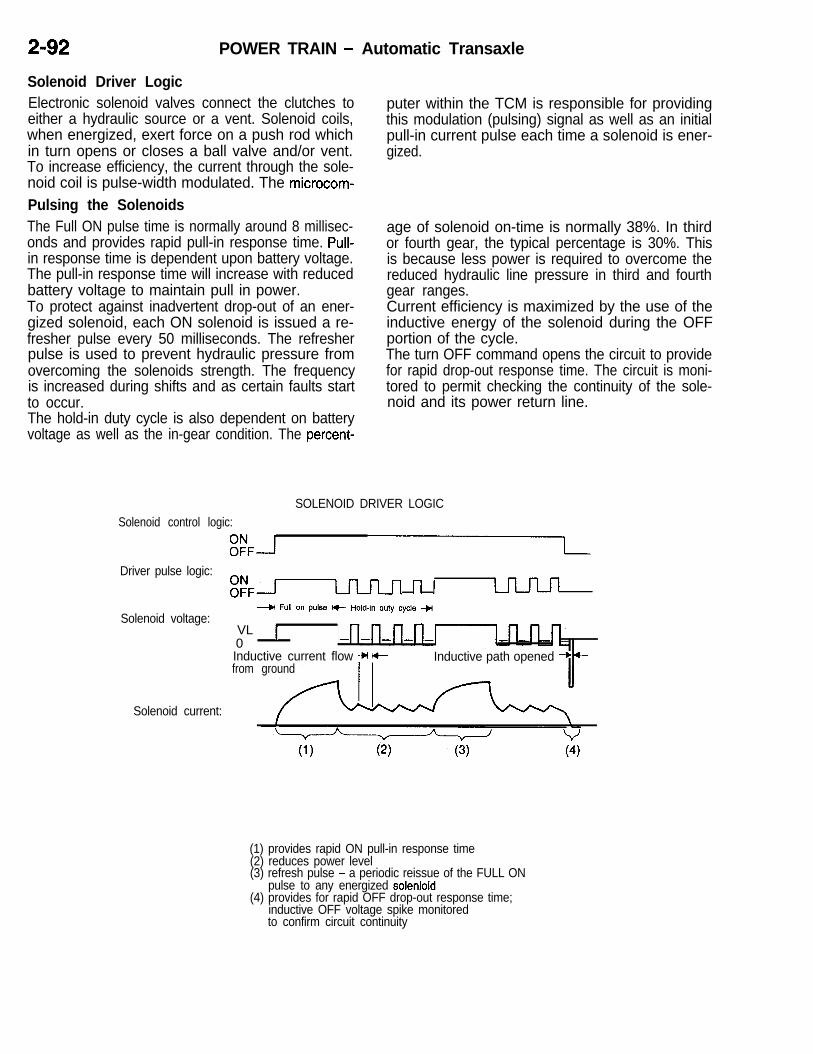
POWER TRAIN - Automatic Transaxle
Solenoid Driver LogicElectronic solenoid valves connect the clutches toeither a hydraulic source or a vent. Solenoid coils,when energized, exert force on a push rod whichin turn opens or closes a ball valve and/or vent.To increase efficiency, the current through the sole-noid coil is pulse-width modulated. The microcom-Pulsing the SolenoidsThe Full ON pulse time is normally around 8 millisec-onds and provides rapid pull-in response time. Pull-in response time is dependent upon battery voltage.The pull-in response time will increase with reducedbattery voltage to maintain pull in power.To protect against inadvertent drop-out of an ener-gized solenoid, each ON solenoid is issued a re-fresher pulse every 50 milliseconds. The refresherpulse is used to prevent hydraulic pressure fromovercoming the solenoids strength. The frequencyis increased during shifts and as certain faults startto occur.The hold-in duty cycle is also dependent on batteryvoltage as well as the in-gear condition. The percent-
puter within the TCM is responsible for providingthis modulation (pulsing) signal as well as an initial dpull-in current pulse each time a solenoid is ener-gized.
age of solenoid on-time is normally 38%. In thirdor fourth gear, the typical percentage is 30%. Thisis because less power is required to overcome thereduced hydraulic line pressure in third and fourthgear ranges.Current efficiency is maximized by the use of theinductive energy of the solenoid during the OFFportion of the cycle.The turn OFF command opens the circuit to providefor rapid drop-out response time. The circuit is moni-tored to permit checking the continuity of the sole-noid and its power return line.
SOLENOID DRIVER LOGICSolenoid control logic:
FFJDriver pulse logic:
Ek- n J H-u-Ln
Solenoid voltage:-+I Full on pulse W- Hold-in duty cycle +j
VL 10Inductive current flow -H I+from ground
Solenoid current:
Inductive path opened --C +
(1) provides rapid ON pull-in response time(2) reduces power level(3) refresh pulse - a periodic reissue of the FULL ON
pulse to any energized solenlcid(4) provides for rapid OFF drop-out response time;
inductive OFF voltage spike monitoredto confirm circuit continuity

POWER TRAIN - Automatic Transaxle 2-93
Solenoid Clutch
OD ON ON
LRJCC ON ON
UD OFF ON
24lLR~ OFF ON
Solenoid and Element LogicSince both normally-ON and normally-OFF solenoids are used,the following logic is recognized by the TCM.The LWCC solenoid controls the LR clutch in first gear, Neutral,and Park and controls the Converter clutch (CC) in second,third, and fourth gears. The solenoid switch valve position deter-mines which clutch (LR or CC) the solenoid will control.The 2-4/LR solenoid controls the 2-4 clutch in Overdrive, Driveand Low. The 2-4/LR solenoid controls the LR clutch in Reverse.
JIn this case, the manual valve position determines which clutchis being controlled.
Gear
Park/Neutral(Under 8 MPH)
Neutral(Over 8 MPH)
Reverse
Reverse(Over 8 MPH)
First
Second
Second EMCC
Third
Third EMCC
Fourth
Fourth EMCC
Solenoids
s2 s3 Sl s4 Manual valve
OD LRKC UD 24/LR
0LR 00
LR R
R00LR UD 0
UD 24
0cc UD 24
UD 0UD 0
0;
0 24
@ 0 24
Solenoid energized = (>Clutch applied = OD, LR, CC, UD, 2-4, R

2-94 POWER TRAIN - Automatic Transaxle
Solenoid Switch Valve Control LogicThis valve protects against the inadvertent applica-tion of LR clutch in second, third, or fourth gearranges. When shifting to first gear, the SolenoidSwitch Valve (SSV) must be in the downshifted posi-tion or action must be taken to shift the SSV intothe downshifted position. As long as any of threepressures (2-4, OD, or UD) are greater than X%of line pressure (X = 60% for UD and OD, 70%for 2-4), the SSV will remain upshifted. To confirmthat the SSV has downshifted, both the LR solenoidand LR pressure switch must be high (voltage valueseen by TCM). To downshift the valve for 3-1 or2-1 shifts, shift logic will briefly vent the UD clutch(shift logic must vent the other two clutches also)and test for valve motion by eneraizing the LR/CC
L/Rclutch
solenoid and verifying that the LR pressure switchturns on.A SSV diagnostic trouble code will only be storedif the transaxle operating temperature range is hot,and the malfunction occurs at least three times.The fault counter is reset during the start routine.Under certain conditions, such as very cold fluidtemperatures, it is possible that the SSV valve maynot move as quickly as it normally would at operatingtemperature. This slow response may occasionallyresult in a second gear launch or a change mindshift to second gear from a 2-l or 3-1 shift. Nodiagnostic trouble code will be set if the transaxleoperating temperature range is cold.
UR clutch 2/4 clutch
IManual
Manualvalve
valve
Clutch Apply StatusTo execute the shift logic, the TCM must maintaina continuous record of each clutch element applystatus. This is done by tracking the instantaneousfluid volumes in each clutch circuit. Instantaneousfluid volumes are tracked using predetermined flowrates and learned “clutch fill volumes”. This is partic-ularly useful for closely-spaced shifts or change-mind shifts.Learned clutch fill volumes represent the volumeof fluid that is required to stroke a clutch pistonto the point where zero clutch pack clearance isobtained. The clutch fill volume learn value is thefill volume without stroking the accumulator or pick-ing up any torque load on the clutch. This learnedfill volume is updated for each clutch element asit wears and clutch pack clearance increases.
Manualvalve
Manualvalve
The Clutch Volume Index (CVI) display of the scantool (MUT-II) can be used to view learned clutchfill volumes for each clutch. The normal range forclutch fill volumes are LR = 35 to 85, OD = 75to 150, 2-4 = 20 to 77, and UD = 24 to 70.If the battery feed is disconnected from the TCM,the learned clutch fill volumes will be lost, and initialvalues will be substituted until correct values canbe re-learned. Shifting may be somewhat harsh.The initial values are; LR = 64, OD = 89, 2-4 =48, and UD = 45.A transmission which has experienced a suddenclutch failure may not be capable of learning thecorrect values. A road test of a transaxle with thiscondition may exhibit an upshift runaway condition,but have acceptable clutch fill volumes.

POWER TRAIN - Automatic Transaxle 2-95Normal Shutdown Routine
iWhen the ignition switch is turned off (column lock,key out position), the TCM will go through a specificshutdown routine.For the first twenty minutes after ignition off, theCPU remains in the “awake” mode. In tills off-timetracking mode, the TCM continues to perform certainfunctions such as predicting fluid temperature cal-culations.Longer off-time tracking is currently prohibited dueto battery drain concerns since the CPU remainspowered up during this time.After 20 minutes have elapsed, the CPU will switchinto a Sleep mode. In this mode the TCM doesnot perform any functions and its Keep Alive Memoryuses only a very small amount of current.The TCM uses a “Keep Alive Memory” that mustalways remain connected to the battery voltage sup-
Fail-Safe RoutineThe TCM is designed and programmed with whatis called a fail-safe routine. This routine constantlymonitors and checks all input and control featuresfor normal operation. The TCM uses inputs fromthe PCM, transmission range and park neutralswitches, input and output speed signals, throttle
iiposition, ignition and pressure switches to determinethe desired outputs. The primary outputs are tothe four solenoid valves which control the transaxleclutches. Changes in these solenoid outputs can
When a failure has been identified which preventscontinued safe transaxle operation, the TCM eventu-ally goes into limp-in by turning off all of the sole-noids. This provides for shift lever controlled opera-tion of SECOND GEAR, NEUTRAL, REVERSE,and PARK. The TCM has logic to ensure the limp-inresults in an ORDERLY SHUTDOWN. Certain fail-ures will prevent an orderly shutdown, and an IM-MEDIATE SHUTDOWN will occur.Orderly Shutdown -A Shutdown routine is activatedwith certain failures prior to opening the transmissioncontrol relay. The result of an orderly shutdown isdependent on the operating condition at the timeof the failure. If the transaxle is in Park, Reverse,Neutral, or Second Gear, there is no additional actionneeded by the TCM. The transmission control relayis opened immediately because the power off stateof the transaxle has already been achieved.If the transaxle is in first gear, then the shutdownsequence (default to second gear) begins immedi-ately.If the transaxle is in third or fourth Gear above 45
b mph, then the current gear range is maintainedto prevent the possibility of causing high enginerpm and/or engine braking.
ply. If the TCM is disconnected, the “Keep AliveMemory” will be lost. This memory is where d/agnos-tic trouble codes and other learned values arestored. These values may be clutch apply and re-lease rates and clutch fill volumes. If the TCM isdisconnected from its direct battery voltage supply,initial stored values are substituted for the erasedlearned values when the CPU is re-initialized. Thesevalues will then be updated as new values arelearned when operating the transaxle.A code 12 will also be stored on any initializationfollowing a direct battery feed disconnection. Code12 lets you know that a direct battery disconnectionhas occurred.
result in changes in clutch pressures, pressureswitch states and input speeds. These changesbecome the new input. If they are not as desired,then the solenoid output is adjusted accordingly.This feed-back control is referred to as a closedloop system and is an integral part of fail-safe.NOTEThe purpose of this section is to cover fail-safelogic. Refer to the Fault Code Explanation sectionfor diagnostic information and probable causes.The actual shutdown sequence to second Gear be-gins once the vehicle speed drops below 45 mph.The exception to this rule is when the vehicle isat high speed and develops a solenoid circuit error.If this occurs, a temporary “neutral” state is gener-ated by venting all clutches to avoid incorrect clutchcombinations - see Codes 41 to 44.The shutdown sequence reduces the possibility ofhaving engine flare-up or clutch overlap (threeclutches applied) as the transaxle defaults to secondgear. This is accomplished by releasing the nonsecond gear clutches slightly before the transmis-sion control relay is opened. This will occur whenthe throttle angle is less than approximately l/3full open. At greater throttle angles, the transmissioncontrol relay is immediately opened. This is donebecause second gear clutches typically apply fasterthan the non second gear clutches. Again, the pur-pose for this sequence of events is to prevent morethan the correct number of clutches from being ap-plied at the same time during moderate throttleangles and to prevent engine flare at higher throttleopenings.

2-96 POWER TRAIN - Automatic Transaxle
Immediate Shutdown -To cause an immediate shut-down to occur, all solenoids are turned off at thesame time. To cause an immediate shutdown thetransmission control relay is opened at the timeof the failure. Default to second gear will take placefrom first, third, or fourth gear. The immediate shut-down may result in clutch overlap at low to moderatethrottle angles and a temporary engine flare with
heavier throttle angles. An engine braking conditionmay also result at high vehicle speeds.At the end of either shutdown routine, the failurecondition will be recorded in memory. The use ofthe scan tool (MUT-II) is required to determine whatthe diagnostic trouble code was at the time of thefailure.
INPUTS
PCM 4-
O Speedsignals--I-l Throttle
0 Ignition
Power -supply
TRANSMISSION CONTROL MODULE
I I I
I- 1h L-f-l I 12v
1 Bus m R A M w I
I;$!; r-f ,,, I OUTPUTS

POWER TRAIN - Automatic Transaxle
DIAGNOSTIC FUNCTION CHART
ii Diagnostic trouble Itemcode No.
11 Internal control module (watchdog circuit test failure)
12 Battery power was disconnected since last power down
13 Internal control module (watchdog circuit shutdown)
14 Relay always On (relay contacts are welded closed)
15 Relay always Off (relay contacts are stuck open)
16 Internal control module (ROM checksum failure)
17 Internal control module (RAM checksum failure)
18 Engine speed sensor circuit
19 CCD bus communication with SBEC
20 Switched battery
21 Pressure switch circuit OD
2-4
2-4/OD
24 LR
LWOD
LR/2-4
27
28 Check shifter signal
All
Throttle position signal
31 Hydraulic pressure switch / OD
/ 2-4
1 OD/2-4
35 Check ATF level
I 36 Fault immediately after a shift
I 37 Solenoid switch valve latched in the LU position
Lockup control out of range
41 Solenoid circuit error LR
1 2-4
43 OD
44 UD
45 Internal control module (engine model EEPROM cell failure)

POWER TRAIN - Automatic Transaxle
Diagnostic trouble Itemcode No.
46 UD hydraulic circuit failure
47 Solenoid switch valve latched in the LR position
50 Speeds error Gear ratio in Reverse
51 Gear ratio in 1st
52 Gear ratio in 2nd
53 Gear ratio in 3rd
54 Gear ratio in 4th
56 Input speed sensor
57 Output speed sensor
58 Speed sensor’s ground
60 Inadequate element volume LR
61 2-4
62 OD

POWER TRAIN - Automatic Transaxle 2-99
TRANSAXLE CONTROL
L
l To prevent abrupt starting made through mis- the transaxle side as well as to that on thetakes in selector lever operation, automatic selector lever side so as to decrease transmis-transaxle fail-safe mechanism (key interlock sion of vibration to the vehicle body.system, shift lock system and reverse “R” posi-tion warning system) has been adopted.
NOTE
Vibration-prevention rubber has been installedFor the reverse ‘9” position warning system,
l
to the transaxle control cable support area onrefer to GROUP 7 - ETACS.
REVERSE “R” POSITION WARNINGSYSTEM
, Inhibitor switch
REVERSE “R” POSITION WARNINGSYSTEM
<Non-turbo> Transaxle rangeswitch/
/c---n SHIFT LOCK SYSTEM
.<
Selector lever
‘L_ / m ViO;on-preve;tion SelectorA,’ lever
Ignition key cylinder
Key interlock cable
Shift lock ca

POWER TRAIN - Automatic Transaxle
A/T FAULTY OPERATION PREVENTIONMECHANISMShift Lock System dUnless the brake pedal is being depressed, theselector lever cannot be shifted to any other positionfrom the “P” position. Moreover, if the ignition keyis in “LOCK” position or if the key has been removed,the selector lever cannot be shifted to any otherposition from “P” position even if the brake pedalis depressed.
1. WHEN BRAKE PEDAL IS NOT DEPRESSEDWhen the selector lever is in “P” position andthe brake pedal is not depressed, the detentpin is locked because the shift lock pin locksthe lock cam, therefore, the selector pushbuttoncannot be pressed and the lever cannot beshifted from the “P” position.
2. WHEN BRAKE PEDAL IS DEPRESSEDWhen the brake pedal is depressed in the afore-mentioned condition 1, the inner cable of theshift lock cable is pulled in the direction of thearrow ( @ ) in the figure and the lock cam,which is interlinked with the shift lock pin, isreleased. As a result, the selector pushbuttoncan be pressed and the selector lever can beshifted from ‘P” position to another position.
,/
3. SHIFTING TO “P” POSITION FROM ANOTHERPOSITIONIn the case of shifting to “P” position from anotherposition (for example, “R” position), the lockcam is held in the position shown in the figureby the force of the shift lock pin return spring;consequently, there is no need to depress thebrake pedal. When the selector lever is shiftedto “P” position and the selector lever pushbuttonis released, the lock cam is rotated leftwardwhile the detent pin moves upward. Conse- dquently, the shift lock pin is pressed down onby the force of the return spring and the lockcam is locked. In this way, the selector leveris held fixed in the “P” position.
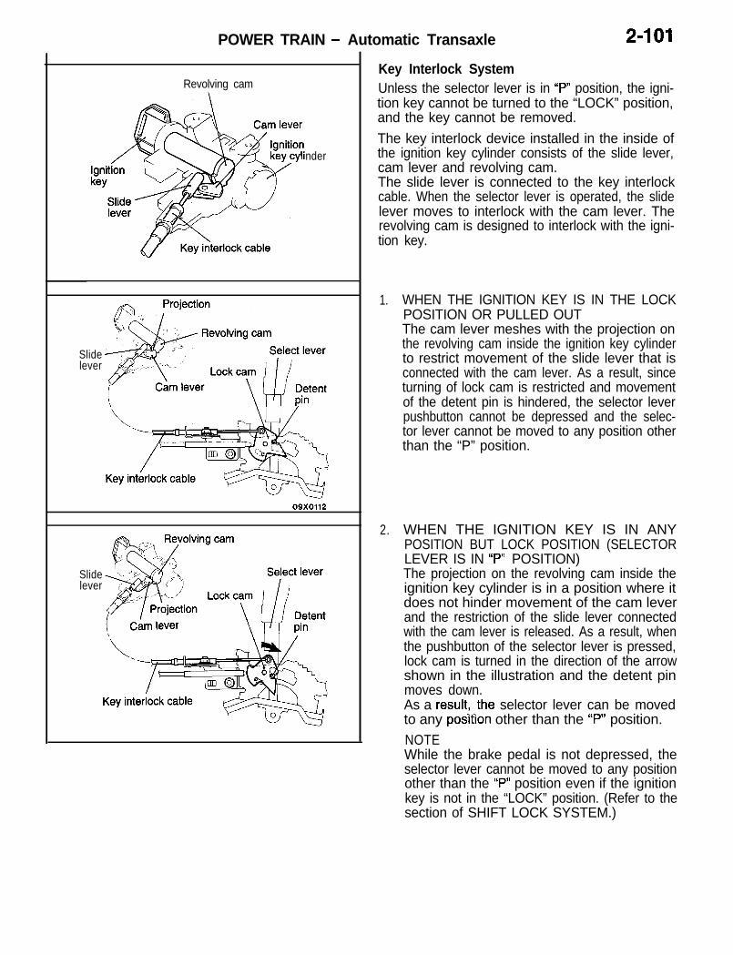
POWER TRAIN - Automatic Transaxle 2-101
Revolving cam
nder
Slidelever
Slidelever
Key Interlock SystemUnless the selector lever is in ‘P” position, the igni-tion key cannot be turned to the “LOCK” position,and the key cannot be removed.The key interlock device installed in the inside ofthe ignition key cylinder consists of the slide lever,cam lever and revolving cam.The slide lever is connected to the key interlockcable. When the selector lever is operated, the slidelever moves to interlock with the cam lever. Therevolving cam is designed to interlock with the igni-tion key.
1.
2.
WHEN THE IGNITION KEY IS IN THE LOCKPOSITION OR PULLED OUTThe cam lever meshes with the projection onthe revolving cam inside the ignition key cylinderto restrict movement of the slide lever that isconnected with the cam lever. As a result, sinceturning of lock cam is restricted and movementof the detent pin is hindered, the selector leverpushbutton cannot be depressed and the selec-tor lever cannot be moved to any position otherthan the “P” position.
WHEN THE IGNITION KEY IS IN ANYPOSITION BUT LOCK POSITION (SELECTORLEVER IS IN “P” POSITION)The projection on the revolving cam inside theignition key cylinder is in a position where itdoes not hinder movement of the cam leverand the restriction of the slide lever connectedwith the cam lever is released. As a result, whenthe pushbutton of the selector lever is pressed,lock cam is turned in the direction of the arrowshown in the illustration and the detent pinmoves down.As a result! .the selector lever can be movedto any posrtron other than the “P” position.NOTEWhile the brake pedal is not depressed, theselector lever cannot be moved to any positionother than the “P” position even if the ignitionkey is not in the “LOCK” position. (Refer to thesection of SHIFT LOCK SYSTEM.)

POWER TRAIN - Automatic Transaxle
Removed section
Select lever
3. WHEN THE IGNITION KEY IS PULLED OUTSelector Lever is a Position Other than “P” Posi-tionLock cam turns in the direction of the arrowshown in the illustration and stays there.As a result, the key interlock cable is caughton lock cam and the cam lever inside the ignitionkey cylinder is turned in the direction of thearrow shown in the illustration (it is in the re-moved section of the revolving cam).Consequently, even if one tries to turn the igni-tion key to the “LOCK” position, the ignitionkey only turns to the “ACC” position since move-ment of the revolving cam is restricted by thecam lever and the key cannot be pulled out.Selector Lever is in “P” PositionThe slide lever inside the ignition key cylinderis pushed in the direction of the arrow by thekey interlock cable and the cam lever turns inthe direction of arrow shown in the illustration.As a result, the revolving cam removes anyrestriction to the rotation of the cam lever soit turns freely and the ignition key can be turnedto the “LOCK” position and can be removed.

POWER TRAIN - Propeller Shaft 2-103
PROPELLER SHAFTL
The AWD vehicles have a 3-section, 4-joint type noise characteristics, In keeping with adoption ofpropeller shaft with center bearings. The center the compact center bearing, the insulator for installa-bearing, provided with front and rear oil seals, is tion of the bearing to the body has been changedcompact, lightweight and has excellent vibration and in shape to further reduce vibration.
SPECIFICATIONS
r Item
Propellershaft
TypeLenath x O.D. mm (in.) 1 Front
Specifications4-joint propeller shaft
676.5 x 65 (26.63 x 2.56)
Universaljoint
Center 642.5 x 65 (25.30 x 2.56)
Rear 634.5 x 50.8 (24.98 x 2.00)
Type No. 1,2,4
No. 3
Cross type
Equal velocity typeLubricationCross type joint journal O.D.
Constant velocity joint O.D.
Pre-packedmm (in.) 14.689 (.5783)
mm (in.) 94 (3.7)
NOTEPropeller shaft length indicates the length between center points of each joint.
CONSTRUCTION DIAGRAMRear propeller shaft/
Center propeller shaftCenter bearing / -.sds-Tv
Heat 1protector 7
Front propeller shaftCenter bearing
seals
Insulator

2-104 POWER TRAIN - Front Axle
FRONT AXLEThe drive shaft use the BJ-TJ constant velocity jointcombination which offers high power transmissionefficiency, ensures smooth inward-outward slidingmovement and transmits less engine vibration dur-ing idling.
FEATURESl The front hub has a press-fitted unit bearing.l The unit bearing consists of inner and outer
races and an oil seal. It features low rotatingresistance and higher protection against mud.
l The front hub assembly bolted to the knuckleimproves serviceability.
l On the AWD vehicles, a center bearing andan inner shaft have been adopted to reducevibration, noise and torque steer.
l On AWD vehicles, dust seals have been pro-vided on both sides of the center bearing and
SPECIFICATIONS
the inner shaft has been press-fitted in the TJouter race for higher protection against mud.
l The drive shafts on some model versions havea dynamic damper for reduction of vibrationand noise.
l The drive shaft and hub area serration coupled.l The ABS equipped vehicles have a wheel speed
detection rotor on the drive shaft and a speedsensor on the knuckle.
l The BJ boots are highly durable plastic ones.
items SpecificationsWheel bearing type Double-row angular contact ball bearingBearing (outside diameter x inside diameter) mm (in.) 84 x 40 (3.31 x 1.57)-
Knuckle
Drive shaft
Rotor<Vehicles with ABS>
T.J. B.J.

POWER TRAIN - Rear Axle <FWD> 2-105
REAR AXLE <FWD> The rear axle is of a design having axle shafts with
press-fitted unit bearings.
FEATURESl The unit bearing consists of inner and outer
races and an oil seal for lower rotating resistanceand higher protection against mud.
l The rear axle shaft bolted to the knuckle im-proves serviceability.
l ABS equipped vehicles have a wheel speeddetection rotor on the rear axle shaft and aspeed sensor on the knuckle.
Rear axle shaft with ABS>
Oil seal
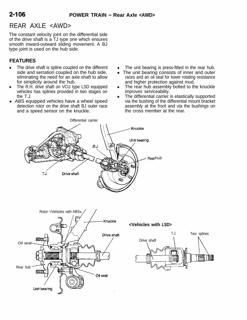
2-106 POWER TRAIN - Rear Axle <AWD>
REAR AXLE <AWD>The constant velocity joint on the differential sideof the drive shaft is a TJ type one which ensuressmooth inward-outward sliding movement. A BJtype joint is used on the hub side.
FEATURESl The drive shaft is spline coupled on the different
side and serration coupled on the hub side,eliminating the need for an axle shaft to allowfor simplicity around the hub.
l The R.H. drive shaft on VCU type LSD equippedvehicles has splines provided in two stages onthe T.J.
l ABS equipped vehicles have a wheel speeddetection rotor on the drive shaft BJ outer raceand a speed sensor on the knuckle.
l The unit bearing is press-fitted in the rear hub.l The unit bearing consists of inner and outer
races and an oil seal for lower rotating resistanceand higher protection against mud.
l The rear hub assembly bolted to the knuckleimproves serviceability.
l The differential carrier is elastically supportedvia the bushing of the differential mount bracketassembly at the front and via the bushings onthe cross member at the rear.
Differential carrier
Oil seal
Rear hub
Rotor <Vehicles with ABS
hub
<Vehicles with LSD>
T.J.
Drive shaft \
Two splines

POWER TRAIN - Rear Axle cAWD> 2-107
DIFFERENTIAL
L
The differential uses a low frictional torque bearing For better cooling of the differential during high-and oil seal to provide improved power and fuel speed operation, the differential carrier has cooling
efficiency. fins.In addition, VCU type LSD is used on some models.
SPECIFICATIONS
Conventional differential Limited slip differential (VCU type)Items
M/T AK M/T AK
Reduction gear type Hypoid gear
Reduction ratio 3.545 3.307 3.545 3.307
Differential gear type(Type x number of gears)
Side gear Straight bevel gear x 2 Straight bevel gear x 2*Pinion gear Straight bevel gear x 2 Straight bevel gear x 2
Number of teethDrive gear 39 43 39 43Drive pinion 11 13 11 13Side gear 14 14 14 16Pinion gear 10 10 10 10
Bearing (outside diameter xinside diameter) mm (in.)
Side 72 x 35 (2.83 x 1.38)Front 62 x 25 (2.44 x .98)Rear 72 x 35 (2.83 x 1.38)
NOTE*: Denotes the gear (L.H.) which is in a single body with the viscous coupling.
Conventional differential
Cooling fin
Limited slip differential (VCU type)

Rear crossmember
Differential mount
2-108 POWER TRAIN - Rear Axle <AWD>
DIFFERENTIAL SUPPORTThe front of the differential carrier is elastically sup-ported by the bushing of the differential mount brack-
et assembly, and its rear is supported by the bush-ings on the rear cross member.
d

3-i
L
CONTENTS
ANTI-LOCK BRAKE SYSTEM (ABS)<AWD> . . . . . . . . . . . . . . . . . . . . ..*....a..... 44
ABS Electrical Circuit Diagram . . . . . . . . . . . . . . 46ABS Hydraulic Function Schematic . . . . . . . . . . 47Actuator . . . . . . . . . . . . . . . . . . . . . . . . . . . . . . . . . . . 50Electronic Control Unit (ECU) . . . . . . . . . . . . . . . 51Sensor . . . . . . . . . . . . . . . . . . . . . . . . . . . . . . . . . . . . 48System Drawing . . . . . . . . . . . . . . . . . . . . . . . . . . . 45
ANTI-LOCK BRAKE SYSTEM (ABS)<FWD> . . . . . . . . . . . . . . . . . . . . . . . . . . . . . . . . . . 27
ABS Electrical Circuit Diagram . . . . . . . . . . . . . . 29ABS Hydraulic Pressure Function Diagram ... 30Actuator . . . . . . . . . . . . . . . . . . . . . . . . . . . . . . . . . . . 32Electronic Control Unit (ECU) . . . . . . . . . . . . . . . 34Sensor . . . . . . . . . . . . . . . . . . . . . . . . . . . . . . . . . . . . 31System Drawing . . . . . . . . . . . . . . . . . . . . . . . . . . . 28
BRAKES . . . . . . . . . . . . . . . . . . . . . . . . . . . . . . . . 22
Construction Diagram . . . . . . . . . . . . . . . . . . . . . . 22Features . . . . . . . . . . . . . . . . . . . . . . . . . . . . . . . . . . 22
FRONT SUSPENSION . . . . . . . . . . . . . . . . . a.. 3Construction . . . . . . . . . . . . . . . . . . . . . . . . . . . . . . . . 5
High-mounted upper arm . . . . . . . . . . . . . . . . . 9Optimized virtual kingpin axis positioning . . . 6Shock absorber with damping forcecontrol valve for very low and lowspeed operation <Turbo> . . . . . . . . . . . . . . . . 10Variation in camber during cornering . . . . . . 10
Features . . . . . . . . . . . . . . . . . . . . . . . . . . . . . . . . . . . 3Specifications . . . . . . . . . . . . . . . . . . . . . . . . . . . . . . . 4
PARKING BRAKES . . . . . . . . . . . . . . . . . . . . . . 59
Construction Diagram . . . . . . . . . . . . . . . . . . . . . . . . 59
POWER STEERING . . . . . . . . . . . . . . . . . . . . . 16Construction . . . . . . . . . . . . . . . . . . . . . . . . . . . . . . . 17Features . . . . . . . . . . . . . . . . . . . . . . . . . . . . . . . . . . 16
Oil Pump . . . . . . . . . . . . . . . . . . . . . . . . . . . . . . . . . . 20Specifications . . . . . . . . . . . . . . . . . . . . . . . . . . . . . . 16
Steering Gear and Linkage . . . . . . . . . . . . . . . . . 21
Steering Shaft and Column . . . . . . . . . . . . . . . . . 18Steering Wheel . . . . . . . . . . . . . . . . . . . . . . . . . . . . 18
REAR SUSPENSION . . . . . . . . . . . . . . . . . . . . 11Construction . . . . . . . . . . . . . . . . . . . . . . . . . . . . . . . 13
Variation in toe angle by rearward forceinput . . . . . . . . . . . . . . . . . . . . . . . . . . . . . . . . . . . 14Variation in toe angle by side forces . . . . . 14
Variation in toe angle on turns . . . . . . . . . . . 14
Features . . . . . . . . . . . . . . . . . . . . . . . . . . . . . . . . . . 11Specifications . . . . . . . . . . . . . . . . . . . . . . . . . . . . . . 12
SERVICE BRAKES . . . . . . . . . . . . . . . . . . . . . . 23
Brake Booster . . . . . . . . . . . . . . . . . . . . . . . . . . . . . 25Disc Brakes . . . . . . . . . . . . . . . . . . . . . . . . . . . . . . . 26
Master Cylinder . . . . . . . . . . . . . . . . . . . . . . . . . . . . 24Rear Drum Brakes . . . . . . . . . . . . . . . . . . . . . . . . . 26Specifications . . . . . . . . . . . . . . . . . . . . . . . . . . . . . . 23
SUSPENSION . . . . . . . . . . . . . . . . . . . . . . . . . . . . 2
Features . . . . . . . . . . . . . . . . . . . . . . . . . . . . . . . . . . . 2
WHEELS AND TIRES . . . . . . . . . . . . . . . . . . . 15
Specifications . . . . . . . . . . . . . . . . . . . . . . . . . . . . . . 15
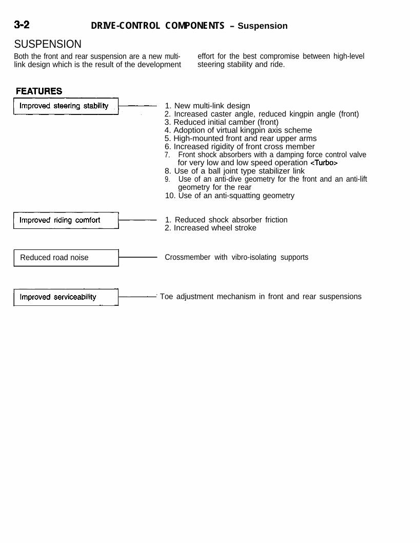
DRIVE-CONTROL COMPONENTS - Suspension
SUSPENSIONBoth the front and rear suspension are a new multi- effort for the best compromise between high-levellink design which is the result of the development steering stability and ride. J
FEATURES
1. New multi-link design2. Increased caster angle, reduced kingpin angle (front)3. Reduced initial camber (front)4. Adoption of virtual kingpin axis scheme5. High-mounted front and rear upper arms6. Increased rigidity of front cross member7. Front shock absorbers with a damping force control valve
for very low and low speed operation <Turbo>8. Use of a ball joint type stabilizer link9. Use of an anti-dive geometry for the front and an anti-lift
geometry for the rear10. Use of an anti-squatting geometry
1. Reduced shock absorber friction2. Increased wheel stroke
Reduced road noise Crossmember with vibro-isolating supports
)- Toe adjustment mechanism in front and rear suspensions

DRIVE-CONTROL COMPONENTS - Front Suspension 3-3
FRONT SUSPENSIONi FEATURES-
The front suspension is similar to that introducedon the 1994 Galant. It is a multi-link structure featur-ing two lower arms by which an ideal virtual kingpin
&?x==Y /Compression lower arm
axis is formed. In addition, the upper arms havebeen raised above the tire level to improve bothdirectional stability and ride.
Crossmember
CentermemberStabilizh bar

3-4 DRIVE-CONTROL COMPONENTS - Front Sumension
SPECIFICATIONS
items
Suspension type
Wheel alignmentCamberCasterToe-in mm (in.)
Coil springWire dia. x O.D. xfree length mm (in.)
Identification colorSpring constant
N/mm (Ibs./in.)
Shock absorberType
Medium price High price
M/T A/T M/T A/T
Multi-link type
-0”05’ Ik 30’ -0”20’ f 30’4”40’ f 1030’ 4”40’ f 1030’0+3(Of.12) 0+3(Of.12)
13.1 x71.1 - 13.2x71.2- 12.9 x 70.9 -111.1 x 309.5
13.1 x 71.1 -111.2 x 315.5 110.9 x 300.5
(52 x 2.80 -111.1 x 306.5
(52 x 2.80 -4.37 x 12.19)
(51 x 2.79 - (.52 x 2.80 -4.38 x 12.42) 4.37 x 11.83)
White + Pink4.37 x 12.07)
White + Gray Yellow + Pink Yellow + Gray
43.0 (245) 43.0 (245) 43.0 (245) 43.0 (245)
Stroke mm (in.)Damping force[at 0.3 m/set. (.9 ft./set.)]
Expansion N (Ibs.)Contraction N (Ibs.)
Hydraulic cylindrical double-acting type118 (4.65)
1,265 - 1,677 (284 - 377)431 - 647 (97 - 146)
Items Premium price
FWD AWD
M/T A/T M/T NT
Suspension type Multi-link type
Wheel alignmentCamber -0”20’ zk 30’ -0”05’ f 30’Caster 4”40’ zk l”30’ 4”40’ * 1030’Toe-in mm (in.) 0+3(0*.12) 0*3(0*.12)
Coil springWire dia. x O.D. x 13.1 x 71.1 - 13.2x71.2-free length
13.3x71.3-mm (in.)
13.5 x 71.5 -111.1 x 306.5 111.2 x 312.5 111.3 x 312.0(.52 x 2.80 -
111.5 x 317.5(52 x 2.80 -
4.37 x 12.07)(.52 x 2.81 -
4.38 x 12.30)(.53 x 2.81 -
Identification color4.38 x 12.28)
Yellow + Gray4.39 x 12.50)
Yellow + Green +Light Blue Light Blue
Green + Purple
Spring constantN/mm (Ibs./in.) 43.0 (245) 43.0 (245) 46.4 (265) 46.4 (265)
Shock absorberType Hydraulic cylindrical double-acting typeStroke mm (in.)
Hydraulic cylindrical double-acting type118 (4.65)
Damping force118 (4.65)
[at 0.3 mkiec. (.9 ft./set.))Expansion N (Ibs.) 1,432 - 1,902 (322 - 428)Contraction
1,471 - 1,961 (331 - 441)N (Ibs.) 470 - 706 (106 - 159) 559-814(126-183)

DRIVE-CONTROL COMPONENTS - Front Suspension 3-5
CONSTRUCTION
idA high mounted upper arm and two lower armsact like a double-wishbone arrangement. In this ar-rangement, a virtual kingpin axis is formed on theline connecting the external vertex of the upper armtriangle and the point where the lines extended fromthe two lower arms intersect. This construction pro-vides the following advantages:l A negative offset geometry is established which
assures better stability during braking.
Link
Upper arm
model Compressionlower arm/
l Reduced offset between the virtual kingpin axisand the wheel center results in a lower steeringmovement at the time when the vehicle is accel-erated or goes over a bump on road, assuringbetter stability.
l The high-mounted upper arm helps improvethe wheel supporting rigidity.
l The multi-link suspension, like a double-wish-bone suspension, suffers little change in “cam-ber to ground” when a rolling motion occurs,assuring better stability during cornering.
Compressionlower arm
Laterallower arm
axis

3-6 DRIVE-CONTROL COMPONENTS - Front Suspension
Double Wishbone SuspensionDouble Wishbone Suspension OPTIMIZED VIRTUAL KINGPIN AXIS POSITIONINGIn a double-wishbone type suspension, the lower point thekingpin axis passes through is the joint between knuckle andlower arm (point A in the illustration at the left). If the double-wishbone type suspension has a high-mounted upper arm,therefore, the extension of the kingpin axis will meet the groundat a point inside the center of the ground contacting area ofthe tire as shown in the illustration (positive offset).
In the case of the multi-link suspension, a virtualkingpin axis is formed in such a way that its lowersection passes through the intersection (point A’as illustrated below) of the lateral lower arm andcompression lower arm extensions. This makes itpossible for the virtual kingpin axis ground meeting
Multi-Link Suspension
Rear View
‘Virtual kingpin axis
Poin
Negative offset
point to be located outside the center point wherethe tire contacts the ground surface (negative offset).In addition, the offset between the wheel center(point C in the illustration) and the kingpin axis canbe made smaller than that in a strut type or double-wishbone type suspension.
Plan View
Front of vehicle
Upper armb-L4Point A’
/
Point
WI I , , , ax

i
DRIVE-CONTROL COMPONENTS - Front Suspension 3-7
Vehicle moving directionThe directiontoward whichthe wheelstend to pull
The direction
P$Ti / j-/T:, ynt
Fc
Large; roadsurfaceresistance
I
Effects of Negative Offset Geometry(1) When the brake pedal is depressed on a running vehicle
with one wheel on a slippery surface, a force is producedwhich causes the vehicle to pull toward the side with largerroad surface resistance (to the right in the case illustratedat the left).
(2) Because of the dynamics resulting from the negative offset,moments Fc and Fo are generated in both wheels aroundpoint A (the point where the kingpin axis meets the ground).Since the magnitude of these moments is proportionalto the road surface resistance, a pull force is producedin the wheels to turn them toward the side with eitherthe Fc or Fb moment whichever is greater (to the leftin the illustrated case).
(3) This means that the wheels pivot toward the direction inwhich the vehicle’s pull force resulting from the differencein road surface resistance is compensated for, thus main-taining the vehicle’s straight-line movement.

3-8 DRIVE-CONTROL COMPONENTS - Front Suspension
Effects of Reduced Wheel Center to Kingpin Axis Offset(1) When the vehicle is accelerated or decelerated, (3) In the multi-link suspension, the offset is as
or when it goes over a projection on road without small as about a third of that in a strut type dbraking, the traction acting on the wheel center suspension and about one half of that in agenerates a moment around the kingpin axis double-wishbone suspension. The reduced off-that would cause the toe angle to change. set, therefore, assures by far better directional
(2) Since the moment is proportionaf to the magni- stability when the vehicle is accelerated or decel-tude of offset between the ‘wheel center and erated, or when it goes over a projection onthe kingpin axis, the smaller the offset, the less road.the change in toe angle, and the better the direc-tional stability.
<Multi-Link Suspension> <Double-Wishbone Type Suspension>&rut Type Suspension>
y -Kingpin axis

DRIVE-CONTROL COMPONENTS - Front Suspension 3-9HIGH-MOUNTED UPPER ARM
iWhen a side force or any other force acts on the it receives smaller camber affecting force astire in a way to change its camber angle, the degree compared to the case with a low-mounted upperof the rigidity that supports the tire depends on the arm (see the illustrations below), and enough wheelhardness of the upper and lower arm rubber bushing. supporting rigi,dity is ensured even with a softerIf the hardness of the bushings is increased, howev- bushing. The high-mounted upper arm and softerer, a larger friction will result during up-and-down bushing combination, therefore, provides a success-motion of the suspension, leading to a poorer ride. ful compromise between soft ride and outstandingThe high-mounted upper arm has made it possible directional stability.to use a softer bushing because the bushing on
Comparison of Forces Acting on Upper Arm Bushing between High-Mounted and Low-MountedUpper Arms
-
<Low-Mounted Upper Arm>
<High-Mounted Upper Arm>
Fu
AUpper arm f \
L2
----_----.
-Point A ,FL
F: Lateral force acting on tireFu: Lateral force caused to act on upper arm by force FFL: Lateral force caused to act on lower arm by force FWhen the equilibrium of moments established at point A inthe illustration is considered, the following formulas hold true.
Fu . L2 = F . L,Fu = F . L1/L2
Also, when the equilibrium of moments established at pointB is considered, the following formulas hold true.
FL . L2 = F . &I + L2)FL = F . (L, + L2)/L2
Assume that L2 = L1 in the case of the low-mounted upperarm and that L2 = 2L1 in the case of the high-mounted upperarm. Then the Fu and FL are expressed as follows:Low-Mounted Upper Arm
Fu = F . L,/L1=F
FL = F . 2L,/L,= 2F
High-Mounted Upper ArmFu = F . L,/2L1
= 0.5FFL = F . 3L,/2L,
= 1.5FIn the case of the high-mounted upper arm, as evident fromthe above, smaller camber affecting forces are input in bothupper and lower arms.

340 DRIVE-CONTROL COMPONENTS - Front Suspension
VARIATION IN CAMBER DURING CORNERINGWhen the steering wheel is turned, camber variesas shown below because of increased caster angleand reduced kingpin angle. On the vehicle with multi-link suspension, the change in “camber to ground”caused by the body rolling during cornering is small
<Variation in Camber during Up-and-Downstroke>
Bump
Strut type suspension
Negative
Camber to ground 0”
Positive
Multi-link suspension -
Rebound 12x0103
by the same action as the one experienced in adouble-wishbone suspension. These effects helpprovide outstanding directional stability by makingthe most of the tire performance.
<Variation in Camber during Cornering>
Innerwheelsteeringangle
Multi-link subpension
Negative
OPERATION <TURBO>When the shock absorber piston speed is at lessthan 0.1 m/set., the control of the damping forceis impossible with the conventional fixed openingorifice alone. This control has been made possibleby adding a relief valve for very low and low speedrange operation. As a result, the damping force
SHOCK ABSORBER WITH DAMPING FORCE CONTROL VALVE FOR VERY LOW AND LOW SPEED
characteristics have become linear as shown below,so that the vehicle provides better feeling whenit rolls and shows better responsiveness to the steer-ing wheel operation.
Piston section
Base Valve AreaVery low andlow speedrelief valve
Notchedrelief valve
- With control valve- With control valve
---- Without control valve---- Without control valve
I
Piston speed m/set.
28

DRIVE-CONTROL COMPONENTS - Rear Suspension 3-11
REAR SUSPENSIONFEATURESThe rear suspension is similar to that introducedon the 1994 Galant. It is a new development inmulti-link design. By properly arranging the individu-al control arms and properly selecting their bushings
for well balanced rigidity, a best compromise be-tween high-level directional stability and riding com-fort has been realized in the suspension.
<FWD>
<AWD>
w Shock absorber
g Upper arm
Toe control arm
I Lower arm
Stabilizer bar
ITrailing arm

3-12 DRIVE-CONTROL COMPONENTS - Rear Suspension
SPECIFICATIONS
Items Medium price High price,Premium price cFWD>
Premium price<AWD>
Suspension type
Wheel alignmentToe-in mm (in.)Camber
Coil springWire dia. x O.D. x free length
mm (in.)
Identification colorSpring constant N/mm (Ibs./in.)
Shock absorberWe
Stroke mm (in.)Damping force[at 0.3 m/set. (.9 ft./set.)]
Expansion N (Ibs.)
Contraction N (Ibs.)
-1”20’ + 30’
11.0x75.0-117.0 x 297.0
(.433 x 2.953 -4.606 x 11.692)
Light Blue + Purple28+1.4(173+8)
Hydraulic cylindricaldouble acting type
164 (6.5)
834- 1,128(187 - 254)314 - 471(71 - 106)
Multi-link type
3 f 3 (.12 zk .12)-1”20’ f 30’*’-1040’ f 30’*2
10.8 x 74.6 -116.6 x 288.0
(.425 x 2.937 -4.591 x 11.339)
Light Blue + Green28f 1.4 (173rt8)
Hydraulic cylindricaldouble acting type
154 (6.1)
834- 1,128(187 - 254)314 - 471(71 - 106)
-1”20’ * 30’*3-1”40’ + 30’*4
11.2x75.4-117.4 x 294.5
(.441 x 2.968 -4.622 x 11.594)
Light Blue + Orange30.4&1.5(162+8)
Hydraulic cylindricaldouble acting type
154 (6.1)
834-1,128(187 - 254)314 - 471(71 - 106)
NOTE*l: Vehicles with 14-inch wheels
: Vehicles with 16-inch wheels
(3) *4: M/T

DRIVE-CONTROL COMPONENTS - Rear Suspension 343
CONSTRUCTION
iA high-mounted upper arm and a combination oflower arm and trailing arm act like a double-wish-bone configuration having a virtual kingpin axis.This construction, like that of the front suspension,provides the following features:l Small offset between the virtual kingpin axis
and wheel center provides better directional sta-bility.
l The high-mounted upper arm helps improvethe tire supporting rigidity and riding comfort.
l Like a double-wishbone suspension, the multi-link suspension features small change in “cam-ber to ground” at the time of a roll, which assuresbetter stability during cornering.
In addition, optimum arrangement of the individualarms and proper selection of the individual bushingsfor well balanced rigidity have provided the followingeffects:l Changes in toe angle caused by the up and
down strokes of the suspension are properlycontrolled for better stability during cornering.
l Changes in toe angle caused by a lateral forceacting on the tire are properly controlled forbetter stability during cornering.
l Even under the effect of a rearward force onthe tire, the wheel alignment does not increasethe “toe-out” tendency. This helps retain thestraight-line motion of the vehicle.

3-14 DRIVE-CONTROL COMPONENTS - Rear Suspension
Bump
Toe-out
Rebound
Toe-in
Toe control arm
VARIATION IN TOE ANGLE ON TURNSWhen the vehicle rolls as it makes a turn, the toe geometrychanges as shown by the characteristics curve at the left underthe effect of the toe control arm action. Also, under the sideforces that are generated during a turn, the toe angle of theouter wheel changes in such a way that the toe-in state willbe maintained thanks to the balance in rigidity of the individualarms’ bushings properly selected for that effect. These charac-teristics allow the rear wheels to make directional changesin phase with the front wheels (steered wheels) during a turn,assuring better steering stability.
VARIATION IN TOE ANGLE BY SIDE FORCESSince the side force acting on the tire causes the bushingsat both ends of the trailing arm to twist in an oblique direction,point A in the illustration is caused to shift toward the centerof the vehicle. The force also acts on the bushings at bothends of the lower arm in their diametric direction, and pointB is consequently displaced toward the center of the vehicleby the amount equivalent to the total deflection of the twobushings (at both ends of the lower arm). The force exertedto the bushing of the toe control arm also acts in the diametric \direction as in the case of the lower arm bushings, but pointC is displaced toward the center of the vehicle only by theamount equivalent to the one bushing’s deflection since pointC is a ball joint.The amount of the displacement of these points are comparedbelow.
(Large Point A > Point B > Point C > (Smalldisplace- displace-ment) ment)
Such being the displacement relationship of the three points,a toe-in state is maintained even in side force conditions.
VARIATION IN TOE ANGLE BY REARWARD FORCE INPUTGenerally, when the vehicle goes over a projection on roador when braking, rearward forces will act on the tires and atoe-out condition will occur because of the resulting compliancesteer. The multi-link suspension, however, maintains a toe-instate as shown at the left thanks to its proper arrangementof the individual control arms even when the vehicle goesover a bump or it is braked and its wheels are subject torearward forces.

DRIVE-CONTROL COMPONENTS - Wheels and Tires 3-15
WHEELS AND TIRESSPECIFICATIONS
Premium price
Items Medium price High price AWDFWD
A/T M/-T
WheelTire size Pl95/7ORl4 P205/55Rl6 P205/55Rl6 89V 215/55Rl6
90H 89H 9lVWheel type Steel type Steel type Aluminum type Aluminum
Aluminum Aluminumtype** type*’
type
Wheel size 14 x 5.5JJ l6x6JJ l6x6JJ l6x6JJAmount of wheel offset
mm (in.) 46 (1.8) 46 (1.8) 46 (1.8) 46 (1.8)Tire inflation pressure
kPa (psi.)Front 220 (32) 220 (32) 220 (32) 220 (32)Rear 200 (29) 200 (29) 200 (29) 200 (29)
Spear wheelTire size Tl25/7ODl5 T125/90D16
Tl25/80Dl 6*2Wheel size l5x4T l6x4T
16~4T*~Amount of wheel offset
mm (in.) 46 (1.8) 46 (1.8)Tire inflation pressure
kPa (psi.) 420 (60) 420 (60)
NOTE(1) *‘:(2) *2:
OptionOption in combination with ABS

3-16 DRIVE-CONTROL COMPONENTS - Power Steering
POWER STEERINGAll models come standard with an engine speedsensitive power steering system.
FEATURES
Engine speed sensitive power steering
1. Impact absorption mechanism2. Supplemental Restraint System (SW)
Double-lip oil seals used in power cylinder
l The 4-spoke type steering wheel with SRS unit l
is adopted on all models.The steering system uses a vane oil pump.with
[For information on the SRS, refer to the “Interiorfluid flow control system.
l
- Supplemental Restraint System (SRS)” sec-The steering gear and linkage system is highly
tion.]reliable integral rack and pinion type which fea-tures light weight and compact size.
l The steering column incorporates both a shockabsorbing mechanism and a tilt steering mecha-
‘d
nism.
SPECIFICATIONS
Items Non-turbo Turbo
Steering wheel maximum turns 2.41
Steering angle (vehicle in unladen)Inner wheel 32”30’ + 2”Outer wheel 27”OO
Steering gear and linkageType Integral typeGear type Rack and pinionGear ratio 00 (infinity)Rack stroke mm (in.) 124 (4.9)
Oil pump type Vane type with fluid flow Vane type with fluid flowcontrol system
Displacement cm3/rev. (cu.in./rev.)control system
10.5 (.64) 9.6 (.59)Relief set pressure MPa (psi.) 8.8 (1,277) 8.8 (1,277)

DRIVE-CONTROL COMPONENTS - Power Steering 3-17
CONSTRUCTION/
Steering wheel
Coolet! pipe
Steering column assembly
<Non-Turbo>
Cooleipipe
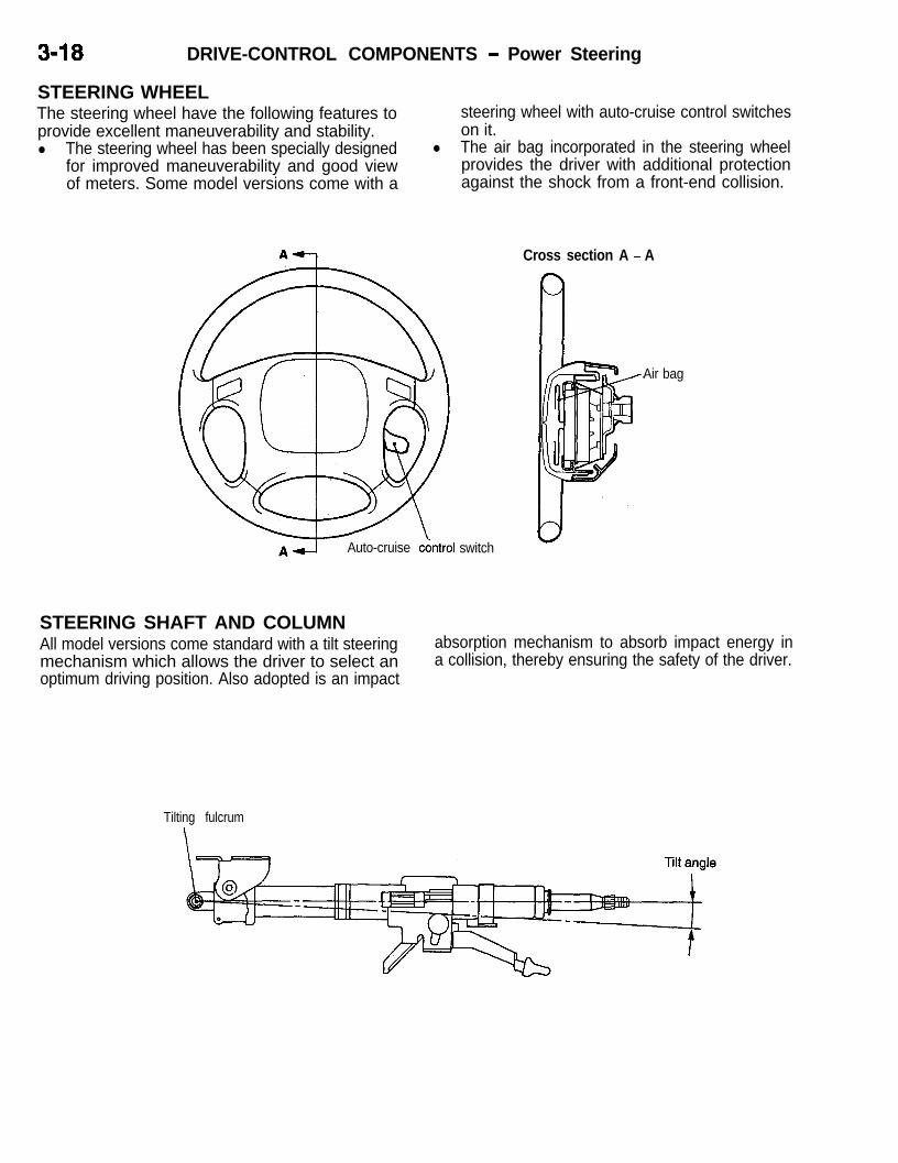
3-18 DRIVE-CONTROL COMPONENTS - Power Steering
STEERING WHEELThe steering wheel have the following features toprovide excellent maneuverability and stability.l The steering wheel has been specially designed
for improved maneuverability and good viewof meters. Some model versions come with a
steering wheel with auto-cruise control switcheson it. Ij
l The air bag incorporated in the steering wheelprovides the driver with additional protectionagainst the shock from a front-end collision.
A1-j Auto-cruise cdntrol switch
Cross section A - A
Air bag
STEERING SHAFT AND COLUMNAll model versions come standard with a tilt steeringmechanism which allows the driver to select anoptimum driving position. Also adopted is an impact
absorption mechanism to absorb impact energy ina collision, thereby ensuring the safety of the driver.
Tilting fulcrum

DRIVE-CONTROL COMPONENTS - Power Steering 3-l 9
BEFORE SHOCK
Shaft assemblyPolyacetal resin
AFTER SHOCK
BEFORE SHOCKColumn bracket
AFTER SHOCK
Cross-section B-B-FTl
SHOCK ABSORBING STRUCTURE
(1)
(2)
0
When the vehicle collides with something andthere is a load added to the steering shaft fromthe gear box (primary shock), the polyacetalresin in the joint assembly is separated, andthe shaft assembly slides into the pipe assembly,absorbing the shock load.
If the driver’s body falls against the steeringwheel (secondary shock), the shock load is ab-sorbed in the following two steps.When a load is added to the steering wheel,the column bracket crushes the polyacetal resinand slides forward, absorbing the shock load.

J
3-20 DRIVE-CONTROL COMPONENTS - Power Steering
BEFORE SHOCK
Steering bushingBellows / Upper column
Lower column
AFTER SHOCK
OIL PUMPThe oil pump is an engine speed sensitive typewhich changes its delivery rate so that the steeringwheel turning effort will always be optimized.
OIL PUMP PERFORMANCE
<Non-turbo>
dm3/min10
eg 8aEz? 69‘-8 4
E12 2
0 10 20 30 40 50 60 70Pump speed (N) (Xl OOr/min.)
L’ **I’ “1 I0 1 2 3 4 5 6 7 8 9
Pump pressure (P) MPa
@ When a shock load is applied to the steeringwheel, the upper column slides forward. At thesame time, the bellows of the steering shaft are deformed. During this process, the shockload is absorbed by the friction between thelower column and the inside surface of the steer-ing bushing attached to the upper column.
<Turbo>
Pump speed (N) (XlOOr/min.)t 11 11 I I I I (0 1 2 3 4 5 6 7 8 9 Ls
Pump pressure (P) MPa
NOTE(1) P-Qf characteristic: Pump pressure and pump delivery rate.(2) N-Qf characteristic: Pump speed and pump delivery rate.

DRIVE-CONTROL COMPONENTS - Power Steerina 3-21
Tie rod end Bear:ng
Lip I I
STEERING GEAR AND LINKAGE(1) The bearings used in the rack end and the tie rod end
ball joints are one-piece type bearings which ensure higherrigidity.
(2) Double-lip type oil seals are used in the power cylinderto improve the reliability.
(3) The pinion shaft side of the steering gear and linkageassembly has been secured directly to the cross memberfor higher rigidity and positional accuracy.

3-22 DRIVE-CONTROL COMPONENTS - Brakes
BRAKESThe brake system offers high dependability and and brake sensitivity.durability along with improved braking performance
FEATURES
/ bm,mrov&b~king1 1. The 4-wheel anti-lock brake system (4ABS) prevents skid-ding that may result from locked wheels, thereby assuringsafe braking.
2. For some models, 2-piston type ventilated disc brakeshave been adopted for front wheels to provide more stablebraking and better braking feel.
3. For some models, a tandem brake booster has beenadopted which provides powerful braking with a light footpressure.
4. For some models, drum-in-disc brakes have been adoptedfor rear wheels. This type of brakes have built-in parkingbrakes which provide outstanding braking stability.
Improvedserviceability
Higher safety
1. For ease of inspection, a self-diagnosis capability has beenadopted for the 4ABS.
2. Both the front and rear brakes use a lug nut mountedouter disc design for ease of removal and installation
3. The master cylinder reserve tank cap is white for easyrecognition
d1. An audible wear indicator alerts the driver to the brake
pad limit.2. Proportioning valves prevent the rear wheels from locking
too quickly3. Front and rear X brake lines.
CONSTRUCTION DIAGRAM

DRIVE-CONTROL COMPONENTS - Service Brakes 3-23
SERVICE BRAKES
iSPECIFICATIONS
FWD
Items Non-Turbo
Medium price Except mediumprice
TurboAWD
Master cylinderType Tandem type Tandem type Tandem type Tandem type
(with level sensor) (with level sensor) (with level sensor) (with level sensor)I.D. mm (in.) 23 8 (15/,6)
2i.4 (l)*23 8 ('5/,6)
25.4 (l)*23 8 (15/,s)2i.4 (l)*
25.4 (1)
Brake boosterType Vacuum type Vacuum type Vacuum type Vacuum typeEffective dia. of power 230 (9) 230 (9) 180+205(7+8) 180+205(7+8)cylinder mm (in.) 180+205(7+8)* 180+205(7+8)* 205+230(8+9)* 205+230(8+9)*Boosting ratio 6.0, 6.5* 6.0, 6.5* 6.5, 7.0* 6.5, 7.0*
Proportioning valveType Dual type Dual type Dual type Dual typeDecompression ratio 0.25 0.25 0.25 0.25
Front brakesType Floating caliper, Floating caliper, Floating caliper, Floating caliper,
single-piston, single-piston, single-piston, single-piston,ventilated disc ventilated disc ventilated disc ventilated disc
Disc effective dia.mm (in.) 204 (8) 204(8) 204 (8) 228 (9)
Wheel cylinder I.D. 60.3 (2 3/s) 60.3 (2 3/8) 60.3 (2 3/s) 42.9 x 2mm (in.) (1 ‘l/,2 x 2)
Rear drum brakesWe Leading-trailing - -
Drum I.D. mm (in.) 203 (8) - - -
Wheel cylinder I.D.mm (in.) 20.6 (13/ts) - -
Lining thicknessmm (in.) 4.4 (.17) - -
Rear disc brakesType Floating caliper,* Floating caliper, Floating caliper, Floating caliper,
single piston, single piston, single piston, single piston,solid disc solid disc solid disc ventilated disc
Disc effective dia.mm (in.) 222 (8.7)* 222 (8.7) 222 (8.7) 237 (9.3)
Wheel cylinder I.D.mm (in.) 34.9 (1 s/s,* 34.9 (1 s/*> 34.9 (1 s/s, 38.1 (1 1/2)
ABSRotor teeth
Front 43 43 43 43Rear 43 43 43 43
Speed sensor Magnet coil type Magnet coil type Magnet coil type Magnet coil type
NOTE *: Vehicles with ABS

3-24 DRIVE-CONTROL COMPONENTS - Service Brakes
MASTER CYLINDERConstructed to provide a maximum measure of safe-ty, the master cylinder offers the following features.l A tandem type master cylinder.l On ABS equipped vehicles, a filter is provided
in the reserve tank to prevent foreign matterfrom entering when adding or replacing brakefluid.
<Vehicles without ABS>
l The reserve tank cap is white for easy recogni-tion which improves serviceability. LJ
l The master cylinder for the ABS equipped ve-hicles incorporates a center valve to cope witha high pressure that is generated when the ABSis in operation.
<Vehicles with ABS>
Filter
ii
Center valve

DRIVE-CONTROL COMPONENTS - Service Brakes 3-25BRAKE BOOSTER
LBrake booster comes in three types: 230 mm (9in.), 180 + 205 mm (7 + 8 in.) and 205 + 230 mm(8 + 9 in.) diameter ones. An appropriate one ofthem is used to each model variation. The tandemtype boosters have two diaphragms each. The two-
<230 mm (9 in.) Brake Booster>
Pushrod
14POO75
480 + 205 mm (7 + 8 in.)Tandem Brake Booster>
Frontgj diaphragm Rear diaphragm
rod
Booster return ’ Reaction discspring Atmospheric
chamberVacuumchamber
diaphragm configuration can utilize a doubled pres-sure difference between the vacuum and the atmo-spheric pressure, so that a large boosting effectcan be obtained with a small outside diameter, there-by contributing to size and weight reduction.
Pushrod
Boosterspring
<205 + 230 mm (8 + 9 in.)Tandem Brake Booster>
Front Rear diaphragmd i a p h r a g m /
LJ Operating
return
Vacuumk4;;$eric
chamber
rod

3-26 DRIVE-CONTROL COMPONENTS - Service Brakes
DISC BRAKESEither single- or double-piston type disc brakes areused for the front wheels, and the single-piston typedisc brakes are used for the rear wheels.l Drum in-disc brakes with dedicated parking
brake shoes and drum.
<Double-piston type>
<Single-piston type>
14X0228
Shoe-to-lever
Adi1 lctnr AI ~“,U”L”’
assemblyParking brakecable
l The outer disc system, which jointly tightensthe wheel and brake disc, improves serviceabili-ty-
l For improved safety, the brake pad employsan audible wear indicator (inside the body).
La<Wear indicator>
/ When new When worn-7
REAR DRUM BRAKESThe rear drum brakes are 205 mm (8 in.)-diameterleading-trailing type brakes which always providestable braking during a forward or reverse move-ment.The drum brakes incorporates an automatic adjustermechanism which automatically adjusts the shoeclearance when the brake pedal is depressed.
Retainer spring

DRIVE-CONTROL CbMPONENTS - A B S <FWD> 3-27
ANTI-LOCK BRAKE SYSTEM (ABS) <FWD>The ABS used in the 1995 Eclipse is similar to
the previous one.The ABS is a brake system which detects skidsthat could be caused by abrupt brake applicationor by brake application on a slippery road surface,and adequately controls the brake fluid pressureto prevent skids caused by locked wheels. It assuresdirectional stability and steerability during brake ap-plication and reduces the brake stopping distance.The basic principles and effects of the ABS arethe same as those of the conventional system.
The major features of the ABS are described below.l When a failure occurs in the system, you can
identify the faulty area in the diagnostic testmode. The failure data stored in memory isnot erased even if the ignition switch is placedin the OFF position. Use of the scan tool enablesyou to read the diagnostic trouble code or clearthe memory. In addition, you can read the sensordata (data list) stored in the electronic controlunit (ECU) and test the hydraulic unit (HU) andother actuators. (Refer to P. 3-43.)
i
Sensor
Part name
Wheel speed sensor
Stop light switch
No. Function
1 Sends an AC signal with a frequency proportional to the ro-tating speed of the individual wheel to the ABS-ECU.
2 Sends a signal to the ABS-ECU indicating whether thebrake pedal is pressed or not.
Hydraulic unit (HU)Controls braking pressure for each wheel depending on the
3 signal from the ABS-ECU.Includes built-in plunger valve
Actuator
Motor relay
Valve relay
4 Closes contact in response to a signal from the ABS-ECU toallow the power to be supplied to the motor in the HU.
5 Is turned ON by the ABS-ECU signal and supplies power tothe solenoid valve in HU.
ABS warning light 6 Is in the combination meter and lights up when there istrouble in ABS.
Data link connector
Electronic control unit (ECU)
7 Outputs diagnostic trouble codes.
8 Controls the actuators such as HU according to the signalsfrom the individual sensors.

DRIVE-CONTROL COMPONENTS - ABS <FWD>
SYSTEM DRAWING
Rear solenoid valveWheel speed sensor (FL)
b FL solenoid valveWheel speed sensor (FR) FR solenoid valveIWheel speed sensor (RR) I
’ /heel speed sensor (RL) FABS valve relay
ABS motor relayABS valve relay response slgnal
ABS-ECU
III
. ”rECU power supply
light
J
II I
1Front right wheel (FR) .
Fi=!E- ---7 Im. I. . . . . I 11 Rear right wheel (RR)
sensor
/I
YI Ieel spew1-^^” -r )(
J
,I---, -----I
J
Front left wheel (FL)sensor vspeed
Rear left wheel (RL:

DRIVE-CONTROL COMPONENTS - A B S <FWD>
ABS ELECTRICAL CIRCUIT DIAGRAMIgnitionswitch IG2
0L10A
ABS-ECU
1 Dedicatedfuse
Hydraulicunit (HU)
ABSmotorrelay
18
1Combinationmeter
ii ::u.I I I-I
26
Dedicatedfuse
Stop lightswitch
pvalve powersupefvision
Sol&oid
FLw- valve {if f
FR RL
Wheel speed sensor
28 30
MR R
23 244-AData linkconnector
1 2 3 4 5 6 7 8 9 10 11 12 13 14 15 16 17 18
19~20~21~22~23~24~25~26~27~28~29~30~31~32~33~34~35
ABS-ECU Connector Pin Configuration

3-30 DRIVE-CONTROL COMPONENTS - A B S <FWD>
ABS HYDRAULIC PRESSURE FUNCTION DIAGRAMThe ABS for FWD operates independently on theright and left front wheels and controls each solenoid
hydraulic pressure is simultaneously reduced in both
valve by sensing each wheel speed sensor. It con-rear wheels through the use of a plunger valve.
trols the solenoid valve for the rear wheels by usingSelect-low: this is a method of providing the same
the rear wheel speed sensor select-low for the righthydraulic control to both wheels when either wheel
and left rear wheels. In other words, when eitheris about to lock, matching it to the side about to
the right or left rear wheel is about to lock, thelock, or a method to control by matching pressureto the low side.
solenoid valve for the rear wheels is activated and
Solenoid
I7valvecontrol
L ---
: /
Wheel speed sensor
Left front 1wheel I
N Master cylinder
valveI-control
Hydraulic unit----_
Wheel speed sensor f
I LRight1 wheeI
I
frcI
mtleft frontwheel4L I
I
IIIIIIII
II
Solenoidvalvercontrol
II
/ F
(11 1 “1 Wheel speed sensor
Proportioning valve
”‘ZD
.Left rear wheel Right rear wheel

DRIVE-CONTROL COMPONENTS - A B S <FWB> 3-31SENSOR
id
WHEEL SPEED SENSORThe wheel speed sensor is a type of pulse generator l For a rear wheel, the rotor (43 teeth) is mountedconsisting of a rotor rotating at the same soeed on the rear hub, and the speed sensor mountedas the wheel and a speed sensor secured to the on the knuckle.knuckle. l For both front and rear wheels, the spacingl For a front wheel, the rotor (43 teeth) is mounted between the sensor and rotor is adjustment-free.
on the front drive shaft and the speed sensormounted on the knuckle.
FRONT REAR
Knuckle , , ,
Drive shaft
+B
TStop light switch
To stop light
sensor
Knuckle
Rear hub
sensor
14X0063
STOP LIGHT SWITCHThe signal from the stop light switch is input to the ABS-ECUas a brake pedal movement signal.When the brake pedal is depressed, the stop light switch circuitcontact closes (ON), and when the brake pedal is released,it opens (OFF). When the contact is closed, the output voltageis at the battery voltage level (HIGH), and when it is opened,the output voltage is at about 0 V (LOW).

3-32 DRIVE-CONTROL COMPONENTS - A B S cFWD>
ACTUATORHYDRAULIC UNIT (HU)l The HU, elastically supported by the shield plate
at the front left of the engine room, consistsof a motor pump, plunger valve, reservoir andthree solenoid valves.
l The HU, positioned between the brake mastercylinder and each wheel cylinder, is a hydrauliccircuit split into two systems associated withthe normal X pipings when the ABS is inactive.
Solenoid
Wheel
When the ABS is active, the motor is operated dby a signal from the ABS-ECU to let the pumpgenerate a hydraulic pressure required to returnfluid against master cylinder pressure. At thesame time, three solenoid valves are operatedto control the hydraulic pressure that acts onthe wheel cylinder.
Solenoid valve and plunger valveRefer to 1991 3000GT Technical Information Manual (Pub. No. PXSE9001).
Hydraulic unit--------___ Master cylinder

DRIVE-CONTROL COMPONENTS - A B S <FWD> 3-33
Pump motor relay m
r----7Ia7 3 0
EY86 ’
a5
L_-_i
14A0145 16R0670
14AO146 16R0670 14A0140
warning
Relay BoxThe motor relay and valve relay are mounted on the hydraulicunit.
MOTOR RELAYThis relay turns the pump motor in the HU ON and OFF.NOTERefer to the section on ECU control for ON/OFF control.
VALVE RELAYThis relay turns current to the solenoid valve in the HU ONand OFF.NOTERefer to the section on ECU control for ON/OFF control.
ABS WARNING LIGHTThis light lights up in case if there is a breakdown in the ABS.Furthermore, it checks whether the bulb is burnt out whenthe engine is started.NOTERefer to the section on ECU Control for warning light control.

3-34 DRIVE-CONTROL COMPONENTS - A B S <FWD>
ELECTRONIC CONTROL UNIT (ECU)l The ABS-ECU detects the vehicle speed in l
terms of a signal from the wheel speed sensorThe ABS-ECU has diagnostic and memoryfunc-tions.
to determine the rotating condition of the wheel,estimates the skidding condition of the wheel
If any failure is found by diagnostic test mode,
on the basis of the predetermined theory, andthe fail-safe function is activated and the ABS
outputs a signal to move the solenoid valvewarning light will illuminate.
in the HU in such a way as to prevent lockingthe wheel.
BLOCK DIAGRAM
ABS-ECU
Battery -
Stop lightswitch
-
Generatorterminal L
-
+ Power CPU II
El .
monitor Operation control,. .
~~~A,~~~
Sensorinterfacecircuit
I ! I I Ir+Motor relay
l rDU monitor circuit drive circuit
)tor, solenoid control, H ItI
t-l+- v,. Mc
mcsnitor circuit Valve relaydrive circuit t
yT&$Jq#-i&ii+fail-safe
I I
I 1 interface circuit 1
-D

DRIVE-CONTROL COMPONENTS - ABS <FWD> 3-35FUNCTION OF INDIVIDUAL CIRCUITS(1) The wheel speed sensor interface circuit converts the AC
voltage signal into DC pulse signal.(2) The power monitor circuit, sensor interface circuit and motor
drive monitor interface circuit are electrical converters forinputting the stop light switch and other vehicle conditionsignals.
(3) The CPU I and II are microcomputers which perform wheelspeed, wheel deceleration and other calculations requiredfor anti-lock control on the basis of the wheel speed signalsinput from the wheel speed sensors, and provides anti-lockcontrols according to the calculated data. The two micro-computers, CPU I and II, monitor each other to detecta failure in the system.They also have diagnostic test mode and failure detectionfail-safe functions.
(4) The solenoid drive circuit, motor relay drive circuit, valverelay drive circuit and ABS warning light drive circuit areelectrical converters for ON/OFF control of the HU solenoidvalves to control the brake fluid pressure, and for ON/OFFcontrol of the motor for producing a high fluid pressurein the HU, and also for lighting the warning light to alertthe driver to a system error.
(5) The failure code memory stores the codes of failures thatoccurred in the system and does not clear the data evenif the battery power supply is disconnected.

3-36 DRIVE-CONTROL COMPONENTS - ABS <FWD>
EXPLANATION OF ECU CONTROLBraking Hydraulic Pressure ControlThe figure below shows the relation between thewheel speed, wheel acceleration, control signal fromthe ECU and braking hydraulic pressure.The ECU uses the signal from each wheel speedsensor to calculate wheel speed and wheel accelera-tion, calculates suspected vehicle speed from theseand monitors the slipping of the wheels. If it seemsthe wheels are about to lock during sudden braking,a signal to reduce pressure or a signal to hold pres-sure is sent to control wheel locking. On the otherhand, if the danger of the wheel locking disappears,a signal to increase pressure is sent and the braking
Wheel speed
Wheel acceleration
Pressure reduction
Signal pressure hole
Pressure increase
Brake hydraulicpressure
4-wheel ControlThe ABS for FWD is a 4-sensor/3channel methodfor independent control of the right and left front
hydraulic pressure is increased to normal mastercylinder pressure. Furthermore, in order to preventa sudden increase in hydraulic pressure at this time,a pulse step control is performed to repeat the signalto increase pressure and the signal to hold pressure.By repeating this cycle and controlling the outputbraking hydraulic pressure, the wheel is kept in anarrow slipping ratio to assure the ideal brakingforce. This hydraulic pressure control is applied inde-pendently to the left front wheel, right front wheeland both rear wheels.
Actual vehicle speed
--\ ---. - - - / e-N
\- - - - - ‘\
Slip ratio set value
--‘..*;-.+;y:;;~;
.-------- j+-fy- ----- --
\$/I‘\\ /\--\\ /-------_ -- ----+.+--
_-----__- 4*---t- - - - - - - - ~ _ _ _ _
control
Time
speed
wheels and select-low control of the rear wheels.
Control SpeedBrake pressure is controlled at a vehicle speed ofapproximately 8 km/h (5 mph) or higher. When ve-
hicle speed falls below approximately 3 km/h (2mph), control ends.

DRIVE-CONTROL COMPONENTS - A B S <FWD> 3-37ABS MOTOR RELAY CONTROL
LJWhen a drive signal is output from the ABS-ECU placed in the ON state to operate the pump motor.to any of the solenoid valves, the motor relay is
ABS VALVE RELAY CONTROLIf the system is found O.K. after an initial check, to supply power to the solenoid valves of the HUthe ABS valve relay is placed in the “ON” state to prepare for operation of ABS.
Approx. 1second
STARTIgnition ONswitch ACC,
LOCK
ABS Warning Light ControlIn the following cases the ABS warning light lights up.l If lights up when trouble in the system is recognized.l It illuminates in the pattern shown in the figure on the
left when the ignition switch is turned ON, to check theABS warning light circuit.
i

3-38 DRIVE-CONTROL COMPONENTS - A B S <FWD>
INITIAL CHECK FUNCTIONThe ECU always performs an initial check on theABS system with the on-board diagnostic function.1. Initial Check Operation(1) When the ignition key is placed in the ON posi-
tion, the power is supplied to the ABS-ECU,and the ABS-ECU starts a diagnostic sequence.During the diagnostic period, the ABS valverelay stays in the “OFF” state and the warninglight continues to light.
If it detects an error, it illuminates the warning light,and disables the ABS system.
(2) Then, the ABS-ECU forces the ABS valve relayinto the “ON” state and executes diagnostic testmode of the ABS valve relay to detect an ONor OFF failure.
(3) All the solenoid valves are caused to be ONand OFF to make sure that the valves are notsticking.
(4) With the ignition key placed in the “START”position and engine started, the voltage at thegenerator terminal L rises. At the moment, theABS-ECU power supply is cut off, but since
,(‘)I (2) , (3)- 4
the ABS valve relay is caused to be “OFF”,the warning light is kept in the ON state bythe ground contact circuit of the ABS valve relay.
(5) If the engine starts and the ignition key is re-turned to the “ON” position, the ABS-ECU powersupply is resumed, and initial checks in (1)through (3) are performed again.
(6) When the initial checks are satisfactorily com-pleted, the ABS becomes ready for operation.The warning light goes out upon detection ofa high voltage at the generator terminal L.
NOTEAn operation check for the motor relay and the motoris performed when the vehicle is put in motion afterstarting the engine. This check is performed onlyone whenever the ignition switch is turned “ON”.
Ignition keySTART
ON .:.ACC .,
ABS-ECUpower supply 12v ,.. .
o v
Generator Highterminal L Ei Or more)
(Less than 6 V)
:: :i.:
ABS warninglight O N --..---‘.
OFF ‘. ,‘.j ‘.’
ABS valverelay ON
I
.
OFF I ‘,. ::
. . . . . . ,. .,: ‘..,‘...’ .,::.: ,.,., .: :
Solenoidvalve ON
OFF

DRIVE-CONTROL COMPONENTS - A B S <FWD>
DIAGNOSIS OF THE WHEEL SPEED SENSOR SYSTEMOn-board diagnosis of the wheel speed sensor sys- is detectable only when the vehicle is put intotern is accomplished by executing the diagnostic motion or when it is running.program stored in the computer. U&g the program,the ABS-ECU monitors each wheel speed sensorsystem (wheel speed sensor, rotor, etc.) to detecta failure. In addition, the ABS-ECU monitors a shortor open circuit in the sensor system by using itsvoltage monitoring circuit and voltage monitoringprogram.The former is called “software failure detection”,whereas the latter is called “hardware failure detec-tion”.(1) Software failure detection
In this diagnostic test mode, the speeds of thefour wheels calculated from the sensor outputsare compared. If there is any sensor systemthat outputs an abnormal speed or an abnormaldecelerated speed, the ABS-ECU determinesthat the system is out of order. Such a failure
FAIL-SAFE FUNCTIONShould a failure occur in the ABS system, the ABS-ECU isolates the system to retain the vehicle’s ordi-nary braking function, thus assuring a high measureof safety.l If the ABS-ECU determines that the system
is defective as the result of diagnosis, it causes
DIAGNOSTIC FUNCTIONSTo facilitate inspection of the ABS system, the ABS-ECU offers the following facilities:l Diagnostic trouble code output and erasurel Data list outputl Actuator testsAll of the items described above can be checkedby the scan tool.
Scan Tool - ABS InterfaceThe scan tool function is entered by connectingthe scan tool to the data link connector. At this time,
(2) Hardware failure detectionThe ABS-ECU monitors the sensors, harness,etc. by using its open/short circuit monitoringcircuit and voltage monitoring program to detecta failure such as an open or short circuit. Amajor feature of the open/short circuit monitoringcircuit is that an open or short circuit failureis always detectable (even when the vehicleis stationary).When the vehicle is in motion, however, a failuremay be detected by software failure detectionfunction before the same open or short circuitfailure is detected by the hardware failure detec-tion function. Such a situation may occur de-pending on the condition of vehicle and thenature of the failure.
the ABS warning light to light, drives the valverelay to interrupt control of the solenoid valvesin the HU, and restores the ordinary brakingmode.
the vehicle must be stopped, and the ignition shouldbe OFF.The ABS scan tool mode is entered when you selectthe ABS system on the scan tool. In this mode,diagnostic output, data list output and actuator testfunctions are available. During an actuator test, how-ever, the ABS warning light illuminates and anti-lockcontrol is inhibited to prevent ABS operation whena brake is temporarily inactivated during the actuatortest.
Scan tool 0 Wheel speeds of 0 km/h (0 mph), parked condi-mode entry tioncondition 0 Check harness of scan tool connected to data
link connector of vehicle0 ABS system selected by control switch of scan
tool (Specified serial data received)
NOTENo communications with the ABS-ECU can be made by con-necting the scan tool while the vehicle is in operation [wheelspeeds not 0 km/h (0 mph)]

3-40 DRIVE-CONTROL COMPONENTS - A B S <FWD>
Diagnostic Trouble CodesConditions detected as a result of diagnosis areassociated with a total of 18 codes including that
These codes are readable by connecting the scan
for normal state, and the codes are stored in thetool. When the scan tool is not used, they are also d
volatile memory.readable from the ABS warning light which is turned
Even if the ignition key is placed in the “OFF” posi-ON and OFF repeatedly in a pattern specific toeach code.
tion, the contents of the memory are not cleared,as the memory remains powered by a backup powersupply.
1. Diagnostic items, diagnostic trouble codes and detection condition
DetectionCode No. display condi-
on Scan tool Inspection item Diagnostic content tions
A B
11*’ Front right wheel speed sensor
12*’ Front left wheel speed sensor
13*’Open circuit or short in +wire x x
Rear right wheel speed sensor
14*’ Rear left wheel speed sensor
15*’ Wheel speed sensor system Abnormal output signal X
1 6*2 Power supply system Abnormal battery positive voltage x x
21*’ Front right wheel speed sensor
22*’ Front left wheel speed sensor Excessive gap
23*’ Rear right wheel speed sensor Long-time radio interferenceX
24*’ Rear left wheel speed sensor
38*3 Stop light switch system Open circuit or ON malfunction x x
41 Front right solenoid valve
42 Front left solenoid valve No response to solenoid valve drivesignal
x x
43 Rear solenoid valve
51 Valve relay Valve relay OFF failure x x
53*4 Motor relay or Motor Motor relay OFF failure and motordrive failure X
63 ABS-ECU ABS-ECU internal failure (programmaze, etc)
x x
No fault codedisplayed (The system is in order)
Detection conditionsA: During system check immediately after startingB: During driving

DRIVE-CONTROL COMPONENTS - A B S <FWD> 3-41NOTE*l: The ABS-ECU can detect only an open circuit from the moment the ECU power supply is ON.
The ABS-ECU lights the ABS warning light when it detects an open circuit, but it does not immediately storethe trouble code in memory and does not cause the system to shut down.When an open circuit is detected, the trouble code is stored in memory and the system caused to shut downwhen the vehicle starts and the wheel speed reaches 6 km/h (4 mph) (the first acceleration after the IG hasbeen placed in the ON state).Troubles other than an open circuit cannot be detected until the wheel speed reaches 6 km/h (4 mph). Whenthe ABS-ECU detects any of these troubles, it causes the system to shut down and simultaneously lights theABS warning light.When the ABS ECU detects a wheel speed sensor error during ABS control, it causes the system to shut downand simultaneously lights the ABS warning light.
*2: The ABS-ECU detects a power supply error when the supplied voltage is a low voltage (approx. 9V or less).When the power supply error is detected, it causes the system to shut down and simultaneously lights the ABSwarning light, but does not store the trouble code in memory. The trouble code is stored in memory when thevoltage returns to normal.When the power voltage is low (approx. 9V or less), none of the trouble codes is stored in memory.
*3: The ABS-ECU takes more than 15 minutes from when it detects an error to when it determines that the faulthas occurred.
*4: The ABS-ECU makes an initial check on the motor relay and motor when the wheel speed reaches 6 km/h(4 mph) for the first time after engine start. If anything wrong is detected, it causes the system to shut downand simultaneously lights the ABS warning light.
<Diagnostic Trouble Code Display by ABS Warning Light>(1) The codes for the currently present or previously tic trouble codes and goes back to the normal
occurred failures are displayed. Each code is control mode. Thereafter, if the ABS systemdisplayed once. After all the codes in store have is in order, the ABS control is available. If thebeen displayed, they are repeatedly displayed, system is out of order, the warning light illumi-beginning with the first one. nates and the brake system is placed in the
(2) If the vehicle is put in motion and any of the ordinary braking mode. No more codes will bewheels reaches a speed of more than IO km/h output until the ignition key is placed in the ON(6 mph) during display of diagnostic trouble position again.codes, the system stops displaying the diagnos-
2. Diagnostic Trouble Code Indication MethodDiagnostic trouble codes are indicated as describedbelow, depending on failure conditions in the system.
I System failure condition I Display on scan tool Display by ABS warning light
No failure detected in the past No diagnostic trouble code displayed. ON/OFF at 0.5 sec. intervals(no-failure code)
detected in the past All codes associated with the failures All codes associated with the failuresthat occurred in the past are displayed, that occurred in the past are displayed,beginning with the most recent one. beginning with the most recent one.
NOTEEven if failures of a same code repeatedly occur, the code that is displayed is the one stored for the first time only.

DRIVE-CONTROL COMPONENTS - ABS <FWD>
3. Diagnostic Trouble Code Clearing ProcedureNOTE(1) When the ABS-ECU system is out of order,
the diagnostic trouble codes in the memory can-not be cleared by use of the scan tool.
(2) To check whether the memory has been cleared,the diagnostic trouble code reading procedureshould be performed.
<When the scan tool is used>Clear the memory according to the message thatappears on the scan tool. (For details, refer to the
<When scan tool is not used>To erase the trouble codes in memory, place thestop light switch in the ON state and then set theignition switch to ON (generator terminal L voltage:LOW) and change over the stop light switch IO
(3) Even after the memory has been cleared, aninstruction from the scan tool can be accepted.To,confirm a diagnostic trouble code, the scantool should be re-operated.
instruction manual for the scan tool.)
times within the following time intervals. The troublecodes in memory will then be erased in about asecond.
Ignition ONswitch
OFFI
Generator HI Iterminal IL voltage LOW ;
Stop light ONI
switch OFF ---iII
I SSC. or ISS
I 1st 2nd 3rd 4th 9th 16thI II I
JWarning ONlight OFF 1 sec.
ABS-ECUmemory
1 sec.1.
Erasure -completed
If any of the following conditions is true, the troublecodes in memory will not erase.l When the stop light switch is not ON before
the ignition switch is set to ONl When the first stop light switch input change
(ON-OFF) does not occur in less than three
seconds, or when the second and subsequentchange does not occur in less than one second
l When the generator terminal L voltage goes“HI” before erasure is completed

DRIVE-CONTROL COMPONENTS - A B S <FWD> 3-43Data List Output
idOf the ABS-ECU input data, the following items can be read by the scan tool.
1. When the System is in Order
Code No. Items Displayed unit
11 Front right wheel speed km/H
12 Front left wheel speed km/H__--
13 Rear right wheel speed km/H
14 Rear left wheel speed km/H
21 ABS-ECU power voltage v
22 Generator power voltage v
23 Stop light switch ON/OFF state ON/OFF
2. When the System is in the ABS-ECU Isolated StateWhen the ABS-ECU is placed in the out of service not displayed. The data displayed by the scan toolstate by the on-board diagnostic program, the wheel is always “0.0 km/h (0 mph)“.speeds of No. 11 through 14 described above areActuator TestThe actuator can be force-driven using the scan actuator testing exceeds 10 km/h (6 mph),tool for easy operation inspection. forced actuation will be cancelled.NOTE (3) The following item numbers are those to be(1) If the ABS-ECU function has been cancelled, entered on the scan tool to give an actuator
an actuator test cannot be performed. test instruction.(2) Actuator testing is only possible when the ve-
hicle is stationary. If the vehicle speed during
Item No.
01
02
03
Drive object Drive pattern
F.R. solenoid valveand pump motor Increase in
Solenoidvalve
F.L. solenoid valveand pump motor
Rear solenoid valveand pump motor
Pumpmotor
Start of forced actuation End of forced actuation
SYSTEM OPERATIONRefer to 1991 3000GT Technical Information Manual (Pub. No. PXSE9001).

DRIVE-CONTROL COMPONENTS - ABS <AWD>
ANTI-LOCK BRAKE SYSTEM (ABS) <AWD>The ABS used in the 1995 Eclipse is similar tothe previous one.
The AWD version ABS is a 4-sensor, 2-channel
Combining the ABS with the AWD system has signifi-type and is the same as the FWD system except
cantly improved the “stopping” as well as “running”for the following respects.
performance of the AWD vehicles. It assures a highl Wheel speed sensor rotor (rear) press-fitted
in drive shaftlevel of running performance under any conditions,not only on a dry pavement but also on a slipperyroad surface.
@ Gap adjustment-free wheel speed sensor androtor
l Semiconductor type G sensor
I 4 7 6
Part name
Wheel speed sensor
No. Function
1 Sends an AC signal with a frequency proportional to the ro-tating speed of the individual wheel to the ABS-ECU.
Sensor G-sensor 2 Sends an ON/OFF signal to the ABS-ECU depending onvehicle acceleration/deceleration.
Stop light switch 3 Sends a signal to the ABS-ECU indicating whether thebrake pedal is pressed or not.
Actuator
Hydraulic unit (HU)
ABS power relay
Motor relay
Valve relay
Controls braking pressure for each wheel depending on the4 signal from the ABS-ECU.
Includes built-in select-low valve
5 Supplies power to the ABS-ECU.
6 Closes contact in response to a signal from the ABS-ECU toallow the power to be supplied to the motor in the HU.
7 Is turned ON by the ABS-ECU signal and supplies power tothe solenoid valve in HU.
ABS warning light 8 Is in the combination meter and lights up when there istrouble in ABS.
Data link connector
Electronic control unit (ECU)-
9 Outputs diagnostic trouble codes.
10 Controls the actuators such as HU according to the signalsfrom the individual sensors.

DRIVE-CONTROL COMPONENTS - A B S <AWD> 3-45
SYSTEM DRAWING
i
Wheel speed sensor (FL)- FL solenoid valve1
Wheel speed sensor (FR)-b
Wheel speed sensor (RR)w
FR solenoid valveABS valve relayABS motor relay
ABS valve relay response signal-
) Fl$iF$rPump m o t o r r e s p o n s e s i g n a l i ABS-ECU 1
G sensorStop light switch
1 ECU power SUDDIV*
r
ft-Stop light switch
\ I
Rear right wheel (RR)
sensor
I ,..A __..I !_
I L’ttl nyaraulic
unit (HU)
(OoA)
I
Wheel speed sensor
Bti A
valve+
1 I
Front right wheel (FR)q=yf&--,-,-‘;
-1
I G sensor
ABS
Rear left wheel (RL)Front left wheel (FL)

3-46 DRIVE-CONTROL COMPONENTS - ABS <AWD>
ABS ELECTRICAL CIRCUIT DIAGRAMIgnitionswitch IG2
IgnitionF u s i b l e l i n k ( 2 )switch IGl,Fusib i-_ nk (2) Fusit link (9)
0LIOA
Dedicated1 [fuseDedicatedfuse
Combinationmeter
Stop lightswitch
ABS powerrelay
$
Diode
1r
iydraulicrnit (HU)
-
.-_
-
L
5I:
I
7
ABSvalverelay
nr
26 7kMotor valverelay relay
a ib Motor ’
7powerSUPPlY
stoplight-Elx Y
FI 1Solenoid
valveId
ABS-ECU
It-
IArIECU power
SUPPlY
-
-
L
2,:
4Resistor
L29
*Wheel speed sensor
1 2 3 4 5 6 7 8 9 10 11 12 13 14 15 16 17 18
19)20~21~22~23~24~25~26(27~26~29~30~31~32~33~34~35
ABS-ECU Connector Pin Configuration

DRIVE-CONTROL COMPONENTS - ABS <AWD> 3-47
ABS HYDRAULIC FUNCTION SCHEMATICThe ABS in the AWD models is of two-channel sys-tem (two-fluid pressure system). In this system, thesolenoid valves are energized or de-energized sothat the front and rear wheel brakes on the sameside are controlled on the “Select Low” rule.For example, when either the front or rear wheelon the right side is about to be locked, all the solenoidvalves on the right side, including those on the frontright wheel, are controlled to hold or slightly reducethe fluid pressure. In order to prevent one wheellocking state in the rear wheels, it is necessaryto control the rear wheels by Select Low as in the
FWD vehicles. In the case of the AWD vehicles,the rear right and left wheels are subject to SelectLow control by the Select Low valves. As a result,the fluid pressure for a total of three wheels (thefront right wheel and the rear right and left wheels)are under simultaneous control.Select-low: this is a method of providing the samehydraulic control to both wheels when either wheelis about to lock, matching it to the side about tolock, or a method to control by matching pressureto the low side.
-Master cylinder
Wheel speed sensor (FR)
u
?ed sensor (FL)?ed sensor (FL)Wheel I
Hydraulic Unit (HU)Hydraulic Unit (HU)r------------r------------
Front left wheel
D il Front right wheel
Solenoidvalve control
Solenoidvalve control
b
cSelect Low
C
T
_)I R e s e r v o i r J)
7 Select Low
I
I
nWheel speedsensor (RR)
Rear right wheel1 1n
Rear left wheel U-J

3-48 DRIVE-CONTROL COMPONENTS - ABS cAWD>
REAR
Knuckle
l-l--i!. RotorLx\(m0
0’
Drive shaft
’ Speedsensor
S E N S O RWHEEL SPEED SENSORThe wheel speed sensor of the AWD vehicle is the same as ‘din the FWD vehicle, except that the rear rotor is mounted onthe drive shaft. (Refer to P. 3-31.)
STOP LIGHT SWITCHThe same as in the FWD vehicle. (Refer to P. 3-31.)
G SENSORThe G sensor, mounted inside the center console panel, detectsthe longitudinal acceleration/deceleration (body G) of the ve-hicle body.
Construction and operationThe inside of the sensor is shown at left. A semiconductorstrain gauge has been adopted as the sensor.

I,
DRIVE-CONTROL COMPONENTS - ABS <AWD> 3-49
L
Piezo diffusionresistor Weight
Dampingoil
9FAOO50
Bridge circuit
Piezo diffusionresistor
/y(G)-0.1 0 1.0
Accele- - Rate of - Decele-ration acceleration ration
outputcharacteristics
Output voltage (V)I
The semiconductor strain gauge type sensor, constructed asshown at the left, consists of a weight mounted at the freeend of an N-type silicon leaf spring, and four P-type diffusionlayers made on the surface of the leaf spring to constitutepiezo diffusion resistors. The case is filled with a dampingoil to prevent breakdown that may be caused by resonance.
The piezo diffusion resistors, arranged as shown at the left,complete a bridge circuit which constitutes a semiconductorstrain gauge.When the sensor is placed under strain by acceleration, thepiezoelectric effect changes its electrical resistance, causingthe bridge circuit to go out of balance.If a voltage is applied across the bridge circuit, the accelerationcan be measured by detecting the amount the bridge circuitgoes out of balance in terms of a change in the voltage.
The output characteristics vary as shown at the left in thedirection of acceleration with 2.5 V as 0 G.

3-50 DRIVE-CONTROL COMPONENTS - A B S <AWD>
ACTUATORHYDRAULIC UNIT (HU)l The HU, elastically supported by the shield plate
at the front left of the engine compartment, con-sists of a motor pump, plunger valve, reservoirand three solenoid valves.
l The HU, positioned between the brake mastercylinder and each wheel cylinder, is a hydrauliccircuit split into two systems associated withthe normal X pipings when the ABS is inactive.
the wheel cylinder.
When the ABS is active, the motor is operated Ljby a signal from the ABS-ECU to let the pumpgenerate a hydraulic pressure required to returnfluid against master cylinder pressure. At thesame time, three solenoid valves are operatedto control the hydraulic pressure that acts on
Solenoi
Hydraulic unitI----- - --------___ 1
/Wheel speed sensor
Master cylinder- -.
Solenoid valve and select-low valveRefer to 1991 3000GT Technical Information Manual (Pub. No. PXSE9001).
Relay boxRefer to P. 3-33.MOTOR RELAYRefer to P. 3-33.VALVE RELAYRefer to P. 3-33.ABS WARNING LIGHTRefer to P. 3-33.
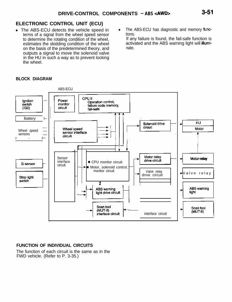
DRIVE-CONTROL COMPONENTS - ABS <AWD> 3-51
ELECTRONIC CONTROL UNIT (ECU)l The ABS-ECU detects the vehicle speed in l The ABS-ECU has diagnostic and memory func-
terms of a signal from the wheel speed sensor tions.to determine the rotating condition of the wheel, If any failure is found, the fail-safe function isestimates the skidding condition of the wheel activated and the ABS warning light will illumi-on the basis of the predetermined theory, and nate.outputs a signal to move the solenoid valvein the HU in such a way as to prevent lockingthe wheel.
BLOCK DIAGRAM
ABS-ECU
1 Battery I--
r - l
Wheel speed 1sensors -
-
Sensorinterfacecircuit
r I 1 I
i J -j-YE%q~0 CPU monitor circuit-+ 0 Motor, solenoid control, -
monitor circuit Valve relay--) drive circuit
f I
~~~~f~iZcuit[
interface circuit
FUNCTION OF INDIVIDUAL CIRCUITSThe function of each circuit is the same as in theFWD vehicle. (Refer to P. 3-35.)
d-5Motor-relay
4V a l v e r e l a y /

3-52 DRIVE-CONTROL COMPONENTS - ABS <AWD>
EXPLANATION OF ECU CONTROLBraking Hydraulic Pressure ControlBraking hydraulic pressure control is the same asin the FWD vehicle. (Refer to P. 3-36.)4-wheel ControlABS on AWD models controls the front and rearwheels using select-low and activates the solenoid
wheels are controlled mechanically in select-low
valve on one side, including either of the frontby the select-low valve, there is, as a result, pressure
wheels. Furthermore, since the rear right and leftcontrol of three wheels (either front wheel and therear right and left wheels) at a time.
FL wheel n FR wheel
Select-low /G5tidl~ ,,’ ~,-
- 1+-rSelect-low
RL wheel wheel
I
SLV: Select-low valve
Control SpeedThe control speed is the same as in the FWD vehicle.(Refer to P. 3-36.)

DRIVE-CONTROL COMPONENTS - ABS <AWD> 3-53
Control with G-sensor
LSince four wheels are connected in AWD models, and a high frictional resistance road and makesthe four wheels may decelerate almost in phase.This tendency is especially strong on a low frictionalresistance road; suspected vehicle speed does notmatch actual speed, the road is judged to be ahigh frictional resistance road and the ABS controlbecomes unreliable. At such a time, the G-sensordistinguishes* between low frictional resistance road
the ABS control reliable by switching the methodof calculating suspected vehicle speed.* When braking on a low frictional resistance road,
the rate of vehicle deceleration is slow. On the ’other hand, when braking on a high frictionalresistance road, the rate of vehicle decelerationis fast.
Warninglight
Approx.1 sec.-
Approx.1 sec.
ABS Warning Light ControlIn the following cases the ABS warning light lights up.l It lights up when trouble in the system is recognized.l It illuminates in the pattern shown in the figure on the
left when the ignition switch is turned ON, to check theABS warning light circuit.

3-54 DRIVE-CONTROL COMPONENTS - ABS <AWD>
INITIAL CHECK FUNCTIONThe ECU always performs an initial check on theABS system with the on-board diagnostic function.
1. Initial Check Operation(1) When the ignition key is placed in the ON posi-
tion, the power is supplied to the ABS-ECU,and the ABS-ECU starts a diagnostic sequence.During the diagnostic period, the ABS valverelay stays in the “OFF” state and the warninglight continues to light.
(2) Then, the ABS-ECU forces the ABS valve relayinto the “ON” state and executes diagnostic testmode of the ABS valve relay to detect an ONor OFF failure.
(3) All the solenoid valves are caused to be ONand OFF to make sure that the valves are notsticking.
If it detects an error, it illuminates the warning light,and disables the ABS system.
(4) If the engine starts and the ignition key is re-turned to the “ON” position, the ABS-ECU powersupply is resumed, and initial checks in (1)through (3) are performed again.
(5) When the initial checks are satisfactorily com-pleted, the ABS becomes ready for operation.
NOTEAn operation check for the motor relay and the motoris performed when the vehicle is put in motion afterstarting the engine. This check is performed onlyonce whenever the ignition switch is turned “ON”.
STARTIgnition key ON
ACC
ABS-ECUpower supply 12v
ov . ..i..
ABSwarning light
ABS valve ONrelay
Solenoid ONvalve
OFF

DRIVE-CONTROL COMPONENTS - ABS <AWD> 3-55
FAIL-SAFE FUNCTION
iShould a failure occur in the ABS system, the ABS-ECU isolates the system to retain the vehicle’s ordi-nary braking function, thus assuring a high measureof safety.l If the ABS-ECU determines that the system
is defective as the result of diagnostic test mode,
DIAGNOSTIC FUNCTIONSTo facilitate inspection of the ABS system, the ABS-ECU offers the following facilities:l Diagnostic trouble code output and erasurel Actuator testAll of the items described above can be checkedby the scan tool.
Scan Tool - ABS InterfaceThe scan tool function is entered by connectingthe scan tool to the data link connector. At this time,
i
it causes the ABS warning light to light, drivesthe valve relay to interrupt control of the solenoidvalves in the HU, and restores the ordinary brak-ing mode.
the vehicle must be stopped, and the ignition shouldbe OFF.The ABS scan tool mode is entered when you selectthe ABS system on the scan tool. In this mode,diagnostic output, data list output and actuator testfunctions are available. During an actuator test, how-ever, the ABS warning light illuminates and anti-lockcontrol is inhibited to prevent ABS operation whena brake is temporarily inactivated during the actuator
Scan tool 0 Wheel speeds of 0 km/h (0 mph), parked condi-mode entry tioncondition Q Check harness of scan tool connected to data
link connector of vehicle0 ABS system selected by control switch of scan
tool (Specified serial data received)
NOTENo communications with the ABS-ECU can be made by con-necting the scan tool while the vehicle is in operation [wheelspeeds not 0 km/h (0 mph)].

3-56 DRIVE-CONTROL COMPONENTS - ABS <AWD>
Diagnostic Trouble CodesConditions detected as a result of diagnosis areassociated with a total of 14 codes including thatfor normal state, and the codes are stored in thevolatile memory.Even if the ignition key is placed in the “OFF” posi-tion, the contents of the memory are not cleared,as the memory remains powered by a backup powersupply.
These codes are readable by connecting the scantool.When the scan tool is not used, they are also read-able with a voltmeter which deflects in a patternunique to each code.
1. Diagnostic items, diagnostic codes and detection condition
DetectionCode No. display Inspection item
condi-on Scan tool Diagnostic content tions
A B
11*’ Front right wheel speed sensor
12*’ Front left wheel speed sensor
13*’ Rear right wheel speed sensorOpen circuit or short in + wire x x
14*’ Rear left wheel speed sensor
15*’ Wheel speed sensor system Abnormal output signal X
21 G sensor Broke wire in G sensor or OFF mal-function X
22*2 Stop light switch system Open circuit or ON malfunction X
41 Front left solenoid valve No response to solenoid valve drive42 Front right solenoid valve signal X
43
51
53*3
55
No fault codedisplayed
Rear solenoid valve
Valve relay
Motor relay or Motor
ABS-ECU
(The system is in order)
Current value in both valves is differ-ent when in same mode X
Valve relay OFF failure x x
Motor relay OFF failure and motordrive failure X
ABS-ECU internal failure (programmaze, etc)
x x
Detection conditionsA: During system check immediately after staritngB: During operation

DRIVE-CONTROL COMPONENTS - ABS <AWD> 3-57
NOTE*l: The ABS-ECU can detect only an open circuit from the moment the ECU power supply is ON.
iThe ABS-ECU lights the ABS warning light when it detects an open circuit, but it does not immediately storethe trouble code in memory and does not cause the system to shut down.When an open circuit is detected, the trouble code is stored in memory and the system caused to shut downwhen the vehicle starts and the wheel speed reaches 6 km/h (4 mph) (the first acceleration after the IG hasbeen placed in the ON state).Troubles other than an open circuit cannot be detected until the wheel speed reaches 6 km/h (4 mph). Whenthe ABS-ECU detects any of these troubles, it causes the system to shut down and simultaneously lights theABS warning light.The shut down responce time varies with the wheel speed as described below.First start after engine start:l When the wheel speed is less than 10 km/h (6 mph), the system shuts down 60 seconds later.l When the wheel speed is 10 km/h (6 mph) or more, the system shuts down immediately.Restart:l When the wheel speed is less than 20 km/h (12 mph), the system shuts down 60 seconds later.l When the wheel speed is 20 km/h (12 mph) or more, the system shuts down immediately.When the ABS-ECU detects a wheel speed sensor error during ABS control, it causes the systemto come down and simultaneously lights the ABS warning light after ABS control.
*2: The ABS-ECU takes more than 15 minutes from when it detects an error to when it determines that the faulthas occurred.
*3: The ABS-ECU makes an initial check on the motor relay and motor when the wheel speed reaches 6 km/h(4 mph) for the first time after engine start. If anything wrong is detected, it causes the system to shut downand simultaneously lights the ABS warning light.
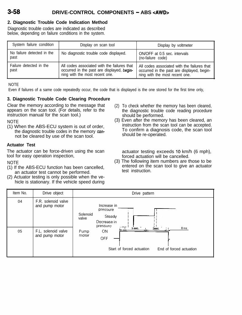
3-58 DRIVE-CONTROL COMPONENTS - ABS <AWD>
2. Diagnostic Trouble Code Indication MethodDiagnostic trouble codes are indicated as describedbelow, depending on failure conditions in the system.
System failure condition
No failure detected in thepast
Failure detected in thepast
Display on scan tool Display by voltmeter
No diagnostic trouble code displayed. ON/OFF at 0.5 sec. intervals(no-failure code)
All codes associated with the failures thatoccurred in the past are displayed, begin-
All codes associated with the failures that
ning with the most recent one.occurred in the past are displayed, begin-ning with the most recent one.
NOTEEven if failures of a same code repeatedly occur, the code that is displayed is the one stored for the first time only,
3. Diagnostic Trouble Code Clearing ProcedureClear the memory according to the message thatappears on the scan tool. (For details, refer to the
(2) To check whether the memory has been cleared,
instruction manual for the scan tool.)the diagnostic trouble code reading procedureshould be performed.
NOTE (3) Even after the memory has been cleared, an(1) When the ABS-ECU system is out of order, instruction from the scan tool can be accepted.
the diagnostic trouble codes in the memory can- To confirm a diagnosis code, the scan toolnot be cleared by use of the scan tool. should be re-operated.
Actuator TestThe actuator can be force-driven using the scantool for easy operation inspection,NOTE(1) If the ABS-ECU function has been cancelled,
an actuator test cannot be performed.(2) Actuator testing is only possible when the ve-
hicle is stationary. If the vehicle speed during
actuator testing exceeds IO km/h (6 mph),forced actuation will be cancelled.
(3) The following item numbers are those to beentered on the scan tool to give an actuatortest instruction.
Item No.
04
05
Drive object
F.R. solenoid valveand pump motor
F.L. solenoid valveand pump motor
Drive pattern
Increase in
Solenoidvalve
;;;ij’ijiq44 ms+r
3sec. I;;; ,9”: I1 *ms
Start of forced actuation End of forced actuation

DRIVE-CONTROL COMPONENTS - Parking Brakes 3-59
PARKING BRAKESl The parking brake for all models is a mechanical 0
control type acting on the rear wheels. The brakeThe parking brake lever is offset torward the
is either a drum type or a drum-in-disc type.front passenger’s seat side.
CONSTRUCTION DIAGRAM


4-1
i
BODYCONTENTS N74ZAOOM
DOORS . . . . . . . . . . . . . . . . . . . . . . . . . . . . . . . . . . . . 7Door Lock.. . . . . . . . . . . . . . . . . . . . . . . . . . . . . . . . . . . 7Door Panel . . . . . . . . . . . . . . . . . . . . . . . . . . . . . . . . . . . 7Window Glass Regulator . . . . . . . . . . . . . . . . . . . . . 11
ELECTRIC SUNROOF . . . . . . . . . . . . . . . . . . . . . 20Sunroof Control System . . . . . . . . . . . . . . . . . . . . . . 20Sunroof Control Unit . . . . . . . . . . . . . . . . . . . . . . . . . 21
GENERAL DESCRIPTION . . . . . . . . . . . . . . . . . . . 2
i; Features . . . . . . . . . . . . . . . . . . . . . . . . . . . . . . . . . . . . . .
KEYLESS ENTRY SYSTEM . . . . . . . . . . . . . . . . 15Receiver .................................... 17Structure and Operation . . . . . . . . . . . . . . . . . . . . . . 16
MAIN BODY . . . . . . . . . . . . . . . . . . . . . . . . . . . . . . . 3Body Color Charts . . . . . . . . . . . . . . . . . . . . . . . . . . . . 4Body Paneling . . . . . . . . . . . . . . . . . . . . . . . . . . . . . . . . .
REDUCTION OF AERODYNAMIC NOISE . . . . 5Flush Surface . . . . . . . . . . . . . . . . . . . . . . . . . . . . . . . . 5Glass Catch . . . . . . . . . . . . . . . . . . . . . . . . . . . . . . . . . . .

4-2 BODY - General Description
GENERAL DESCRIPTIONThe main body (monocoque body) is highly-rigidand excellent in noise and vibration reduction. It
The keyless entry system which allows the doorsto be locked and unlocked by remote control has d
also reduces vehicle weight. also been adopted.
FEATURES
Light weight, added rigidity 1.2.
Corrosion control 1. Extensive use of anticorrosion steel panels2. Application of rocker panel primer to the side sills
Improved controllability andsafety
1.
2.
3.
4.
Extensive use of high tension steel panelsEffective use of reinforcement to improve the rigidity ofdoor outer panel
Tapering at each body cornerGlass area surfaces made flush with body paneling ijEffective arrangement of sound absorbing and insulatingmaterials
Side door beam to enhance occupant’s safety in side colli-sionCentral door lock system with key reminder system <Somemodels>Radio wave remote control type keyless entry system (Op-tion)Power window switch with a one-touch-open mechanism
Improved merchantability 1.and appearance 2.
Flush surface bodyMotor driven outer slide glass sunroof with tilt-up mecha-nism (Option)

BODY - Main Bodv 4-3
MAIN BODYBODY PANELINGThe body features a monocoque construction. Am- steel panels not only reduces the body weight butple use of high-tensile steel panels and galvanized ensures good corrosion control.
m : High-tensile steel panels: Galvanized steel panels

4-4 BODY - Main Body
BODY COLOR CHARTS
Color Body color code
WHITE w12
SILVER A52
GRAY A74
BLACK x13
RED R87
COPPER RED PO1
YELLOW Y76
GREEN G36
BLUE 873
31 W12A74* ,“:,’
Color number
AC10812
AC11052
AC11074
AC10813
AC1 0987
AC11101
AC11076
AC11036
AC11073
AC10812
AC11074
SILVER A52 AC11 052A52A74*
GRAY A74 AC11074
51 X13A74* :;;’ AC10813
AC11074
FFi R87A74* ;;;AC1 0987
AC11074
COPPER RED
GRAY
YELLOW
GRAY
GREEN
GRAY
BLUE
GRAY
POlA74*
Y76A74*
- G36A74*
B73A74*
PO1
A74
Y76
A74
G36
A74
673
A74
AC11101
AC11074
AC11076
AC1 1074
AC11036
AC11074
AC11073
AC11074

BODY - Reduction of Aerodynamic Noise 4-5
REDUCTION OF AERODYNAMICFLUSH SURFACEThe glass areas have been made flush with thebody paneling for less aerodynamic noise and higherdirectional stability during high-speed operation.
Tapering at rearDillar sections
I Tapering at rearside sections
Tapering at frontside corners
Section B - B
glass
NOISE
Section C - C
Additional body design features for these purposesinclude round-shaped body, tapering at each corner,beadless flat floor for smoother under-floor air flow,etc.
Liftgateglass
Section A - A
Windshield
Section D - D
Quarter window

4-6 BODY - Reduction of Aerodvnamic Noise
GLASS CATCHSince sashless doors have been adopted, glasscatches have been provided in the weatherstrip hold-
operation. This also improves sealing between the
ers to prevent the door glasses from being drawnweatherstrip and door glass. This reduces noisegenerated by the air drawn out by negative pressure Lj
outward by the negative pressure during high-speed during high-speed operation.
Section A - A
Door
4i2v Vdo~$erstrip
Glass catch
Glass in normalposition

BODY - Doors 4-7DOORS
DOOR PANELTo ensure safety of the driver and passengers ina side collision, a reinforcement (side door beam)has been installed inside the door.
DOOR LOCKA key reminder equipped central door lock systemhas been adopted. This allows all the doors to belocked and unlocked by the key or door lock switchat either the driver’s or front passenger’s door.(Some models)The central door lock system offers the followingfeatures.l The driver’s door only can be unlocked by oper-
ating the driver’s door key once. All the doorscan be unlocked by operating the key twice.
Outside handle\
tch
Inside handle
Door lock actuator
beam
l All the doors can be locked by the driver’s doorinside lock knob.
l The keyless entry system has been adoptedwhich allows operation of the central door locksystem by remote control. (Option)
l Key reminder equipment (Refer to GROUP 7ETACS.)
<Driver’s side>
<Passenger’s side>
Door lockswitch

4-8 BODY - Doors
Fusible link
Door lockpower relay
Door lockactuator (R.H.)
Door lockkey cylinderswitch (L.H.)
Fusible link
rt
Door IOCKkey cylinderswitch (L.H.)
CENTRAL DOOR LOCKING SYSTEM OPERATION1. Door Locking Operation(1) Door locking operation by Inside Lock Knob or d
KeyWhen the driver’s lock knob or door key is placedin the lock position, the door lock actuator switchis forced to OFF by a mechanical link. The OFFsignal from the actuator switch is input to theETACS. In response to the signal, the ETACSdelivers a lock output. Accordingly, the lock sidecoil of the door lock power relay is energizedto operate the door lock actuators and lock thedoors.
(2) Door locking operation by door lock switchWhen the lock side of the door lock switch isturned ON, the lock side coil of the door lockpower relay is energized to operate the door lockactuators and lock the doors.

BODY - Doors 4-9
Fusible link
rt
Door lockpower relay
Door lockkey cylinderswitch (L.H.)
Fusible linkI
Door lockkey cylinderswitch (L.H.)
2. Door Unlocking Operation(1) Door Unlocking Operation by Key
When the driver’s door key is operated once to-ward the unlock side, the driver’s door is unlockedby a mechanical link. At the time, the driver’sdoor lock actuator switch signal to the ETACSchanges to ON. In this state, when the driver’sdoor key is operated once again toward the unlockside, the ON signal is input from the door lockkey cylinder switch to the ETACS. In responseto these signals the ETACS delivers an unlockoutput. Accordingly, the unlock side coil of thedoor lock power relay is energized to operatethe front passenger’s door actuator and unlockthe front passenger’s door.
When the front passenger’s door key is placedin the unlock position, the unlock side coil ofthe door lock power relay is energized to operatethe door lock actuators and unlock all the doors.

4-10 BODY - Doors
Fusible linkI
Door lockkey cylinderswitch (L.H.)
Door lockpower relay
Fusible link
OFF (Key in position) ON (Door open)
(2) Door Unlocking Operation by Door Lock SwitchWhen the unlock side of the door lock switchis turned ON, the unlock side coil of the door lock power relay is energized to operate the doorlock actuators and unlock the doors.
DOOR LOCKING PREVENTED WITH KEY INIGNITION SWITCH(1) When any of the doors is opened with the key
inserted in the ignition switch (key reminderswitch), the signals from the key reminder switchand door switch are input to the ETACS.
(2) In this state, when the driver’s door inside lockknob is placed on the lock side (the OFF signalfrom the actuator switch input to the ETACS),an unlock output is supplied from the ETACSfor 5 seconds.
(3) This moves the door lock actuator to the unlockside. Therefore, the door cannot be locked unlessthe key is removed from the ignition switch (keyreminder switch) or the door is closed.
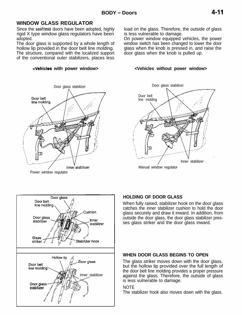
BODY - Doors 4-11WINDOW GLASS REGULATORSince the sashless doors have been adopted, highlyrigid X type window glass regulators have beenadopted.The door glass is supported by a whole length ofhollow lip provided in the door belt line molding.The structure, compared with the localized supportof the conventional outer stabilizers, places less
<Vehicles with power window>
Door glass stabilizer
Power window regulator
Inner stabilizer
load on the glass. Therefore, the outside of glassis less vulnerable to damage.On power window equipped vehicles, the powerwindow switch has been changed to lower the doorglass when the knob is pressed in, and raise thedoor glass when the knob is pulled up.
<Vehicles without power window>
Door glass stabilizer
Door beltline molding
Inner stabilizerManual window regulator
HOLDING OF DOOR GLASSWhen fully raised, stabilizer hook on the door glasscatches the inner stabilizer cushion to hold the doorglass securely and draw it inward. In addition, fromoutside the door glass, the door glass stabilizer pres-ses glass striker and the door glass inward.
WHEN DOOR GLASS BEGINS TO OPENThe glass striker moves down with the door glass,but the hollow lip provided over the full length ofthe door belt line molding provides a proper pressureagainst the glass. Therefore, the outside of glassis less vulnerable to damage.NOTEThe stabilizer hook also moves down with the glass.

4-12 BODY - Doors
OPERATION OF POWER WINDOWSOperation of Power Windows When Controlled by Main SwitchWhen the ignition switch is placed at IG1, currentis supplied from the ETACS-ECU to the coil
(3) Even after the ignition switch has been placed dat OFF, the power window can be operated
of the power window relay. This causes thepower window relay to be ON.
for a period of 30 seconds. During this period,
(2) Current is supplied from the power window relayhowever, the output is interrupted the moment ~
through the main switch to the power windowthe door is opened.
motor to operate the power window.
Powerrelay
Fusible link
I
OFF
t-
t.r
/\ /\I\ /\
window
c \/\, x,
I I;D
Power windowmain switch
Ignition switch (IG1) Fusible link
Power window ON
Constantszvoltage 12V
Constantvoltage 5V
II
1
switch Door switchW-U
Power windowPowerwindowmotorW-0
PowerwindoumotorW-f)

BODY - Doors 4-132. Operation of Power Windows When Controlled by Sub Switches(1) When the ignition switch is placed at IG,, current (3) Even after the ignition switch has been placed
is supplied from the ETACS-ECU to the coil at OFF, the power window can be operatedof the power window relay. This causes the for a period of 30 seconds. During this period,power window relay to be ON. however, the output is interrupted the moment
(2) Current is supplied from the power window relay the door is opened.through the sub switch to the power windowmotor to operate the power window.
Power windowrelay
Power windowmain switch
Fusible link Ignition switch (IG,)
FuseJ
d ETACS-ECU
Fusible link
Ignition switch
Door switchp#~
P o w e r w i n d o w ONoutput oFF j-l--;
Powerwindowmotor0-W
Power windowsub-switch
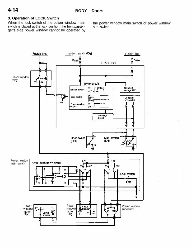
Powerrelay
window
Power windowmain switch
Ignition switch (IG,) Fusible link
Fuaeg ETACS-EC” --Fv V
Door switch
4-14 BODY - Doors
3. Operation of LOCK SwitchWhen the lock switch of the power window mainswitch is placed at the lock position, the front passen-
the power window main switch or power windowsub switch.
ger’s side power window cannot be operated by
PowerwindowmotorWI
PowerwindowmotorW-U
Power windowsub-switch

BODY - Keyless Entry System 4-15
KEYLESS ENTRY SYSTEMi
The radio wave remote control type keyless entrysystem has been adopted. The system is similarto the one introduced on the 1993 3000GT. It allowsall the doors to be locked and unlocked by remotecontrol. (Option)The system consists of a transmitter and receiveradded to the conventional central door lock mecha-nism. Even if the keyless entry system fails, thedoors can be locked and unlocked by the key.The system offers the following features.l Because of the radio wave remote control de-
sign, the operating range of the system is about6 m (20 ft.) from the vehicle in all directions.
l The receiver has a built-in memorize/operationchangeover switch (programming switch). Evenif the transmitter is lost, the whole system neednot be replaced. Just program a new transmitterto the receiver.
l The receiver can store two secret codes. There-fore, two transmitters can be used for a singlevehicle.
Receiver
l A timer lock function has been adopted so thateven if the unlock switch of the transmitter ispressed by mistake, all the doors will be re-locked unless any of the doors is opened withina period of 30 seconds after the unlock switchhas been pressed.
l For confirmation of system operation at night,a confirming function flickers the dome lighttwice after the doors have been locked, andkeeps the dome light lit for three seconds afterthe doors have been unlocked. (The dome lightswitch, however, must be in the “DOOR” posi-tion.)
NOTEThe foot light also simultaneously flashes orlights with the dome light.
Transmitter
Drivesignal
Drivesignal
Dome light
‘When locked:Flashes twice.When unlocked:Lights forthree seconds. 1

4-16 BODY - Keyless Entry System
Part name
Transmitter
Receiver
Function
Sends its secret code by the radio wave signals.
Switched over between the operation and memorizing modes by the code registrationswitch.In the operation mode, the receiver compares the signal received from the transmitter bythe built-in antenna with the code stored in the receiver and outputs the drive signal to theETACS-ECU and dome light only when the signal coincides with the code.In the registration (programming) mode, the receiver stores the signals from the transmitterin the EEPROM in the receiver as a new code.
Outline of the System
Operating Section
Transmitterr - - - - - -------~
L-----------j
Lock switch
Indicator light
Battery
Vehicle-Mounted Section
Receiverr - - - - - - - - - - - - - - - - - - - _ _ _
1
Antenna
TI
IStoredcode
Code registrationswitch
Il Dome lightI
Control circuitII
i
I
ETACS-ECU
STRUCTURE AND OPERATIONTRANSMITTERThe transmitter is a key holder type independent of the masterignition key. The transmission switch comprises two switcheswhich independently perform the lock and unlock functions.When the transmission switch is operated, the secret codeunique to the transmitter is transmitted in radio form.The transmitter has an indicator light which lights when thetransmission switch is placed in the ON state. The light makesit possible to confirm switch operation and battery discharge.The battery comprises two lithium cells (CR2016) and offersa life expectancy of about two years at a rate of use of 10times/day.
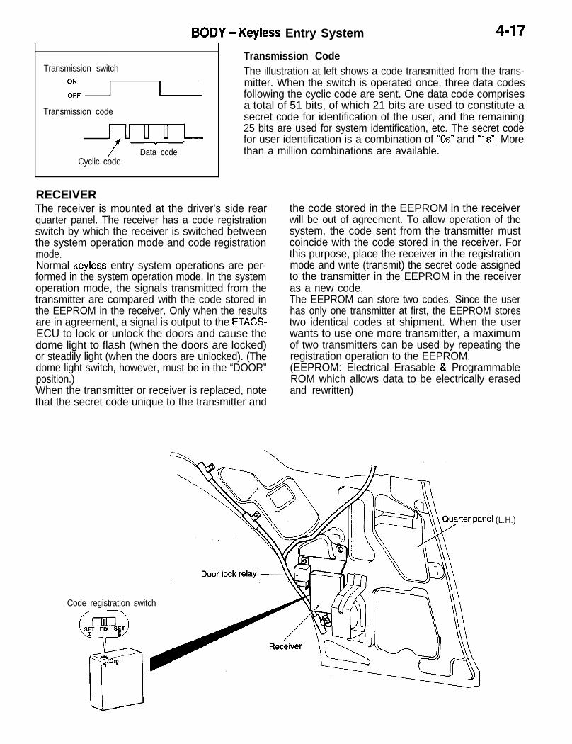
BODY - Keyless Entry System 4-17
Transmission switch
2, -
Transmission code
ir” uvu /lData codeCyclic code
18CO571
Transmission CodeThe illustration at left shows a code transmitted from the trans-mitter. When the switch is operated once, three data codesfollowing the cyclic code are sent. One data code comprisesa total of 51 bits, of which 21 bits are used to constitute asecret code for identification of the user, and the remaining25 bits are used for system identification, etc. The secret codefor user identification is a combination of “OS” and “1s”. Morethan a million combinations are available.
RECEIVERThe receiver is mounted at the driver’s side rearquarter panel. The receiver has a code registrationswitch by which the receiver is switched betweenthe system operation mode and code registrationmode.Normal keyless entry system operations are per-formed in the system operation mode. In the systemoperation mode, the signals transmitted from thetransmitter are compared with the code stored inthe EEPROM in the receiver. Only when the resultsare in agreement, a signal is output to the ETACS-ECU to lock or unlock the doors and cause thedome light to flash (when the doors are locked)
i
or steadily light (when the doors are unlocked). (Thedome light switch, however, must be in the “DOOR”position.)When the transmitter or receiver is replaced, notethat the secret code unique to the transmitter and
the code stored in the EEPROM in the receiverwill be out of agreement. To allow operation of thesystem, the code sent from the transmitter mustcoincide with the code stored in the receiver. Forthis purpose, place the receiver in the registrationmode and write (transmit) the secret code assignedto the transmitter in the EEPROM in the receiveras a new code.The EEPROM can store two codes. Since the userhas only one transmitter at first, the EEPROM storestwo identical codes at shipment. When the userwants to use one more transmitter, a maximumof two transmitters can be used by repeating theregistration operation to the EEPROM.(EEPROM: Electrical Erasable & ProgrammableROM which allows data to be electrically erasedand rewritten)
Code registration switch
(L.H.)

Transmitter switch
Unlock switch
ZFI
Lock switchO N nOFFI I
Signalstransmitted Unlock signal Lock signal
Signalsreceivedby receiver
IDoor unlock signal 1
O N
light (operation confirmation function).NOTEThe receiver determines that the codes are in agree-
IO F F 1 I
the transmitter coincides with the code stored in thement when any of the three codes transmitted from
I receiver.I
Door lock signal !II
O NI
I
O F FI
Door lockII
switch IO N I
(Unlock) 1O F F(Lock) ; ;
I I
Dome light i 1 I I
O NI l I II I
O F FI I
-
0.5 sec. 0.5 sec. 3 sec.
4-18 BODY - Keyless Entry System
OPERATION IN SYSTEM OPERATION MODEWhen the transmission switch is pressed once, threeidentical codes are transmitted from the transmitter.’The secret code is decrypted by the comparator circuit
d
in the receiver which compares the code with thecode stored in the receiver. When the transmittedcode coincides with the stored code, the receiversends a door unlock signal or door lock signal tothe ETACS-ECU.In response to the signal, the doors are locked orunlocked. When the door lock switch in the door lockactuator is caused to be ON (unlock) or OFF (lock),the receiver causes the dome light to flash or steadily
0.5 sec.
Signalsreceivedby receiver
Unlock signalr - l1 I
I
Door unlock signal 1
Door lock signal 1O N I
I
O F F I
I
Door switch H *I 30 sec. I
O N I II I
O F F I II I
Door lock switch I II
O N I I
bUF”:““k’I II I
(Lock)
TIMER LOCK FUNCTIONIf none of the doors is opened in less than 30 secondsafter the doors have been unlocked by the keylessentry system, the receiver will automatically outputa door lock signal to the ETACS-ECU to re-lock thedoors.This function prevents accidental unlocking of thedoors that may be caused by an unintentional opera-tion of the transmitter.Operation Inhibit ConditionsIn the following cases, operation of the system isinhibited.l When a code different from the one stored in
the receiver is received 30 consecutive timesin a minute, operation of the system is inhibitedfor 10 minutes.
l When the ignition key is in the ignition switch(detected by the key reminder switch)
l When any of the doors is not fully closed (doorswitch: ON)

BODY - Keyless Entry System 4-19
L
Code registration switch
V*-<--I *T-"sL3 Receiver
Timing Chart
Coderegistrationswitch
OPERATION IN CODE REGISTRATION MODE(PROGRAMMING)When the code registration switch is in the SETI or SETIIposition, the receiver enters the registration mode where itstores the first received secret code in the EEPROM.Two different secret codes can be stored with the switch inthe SETI and ,SETII positions. Therefore, the user can usetwo transmitters.
SET-l
FIX
SET-II
Signal sent fromtransmitter A
Signal sent fromtransmitter B
Valid-
Signal receivedby receiver
1 ’SET-I Starts acceptingsecret codeto be stored.
Invalid Valid Invalidr--7 r--qI I I II I I I
I
’ ’ i sE!ll “:‘-; ! /
Secret code is stored in EEPROM whenthe switch is changed over from SET-lor SET-II to FIX.
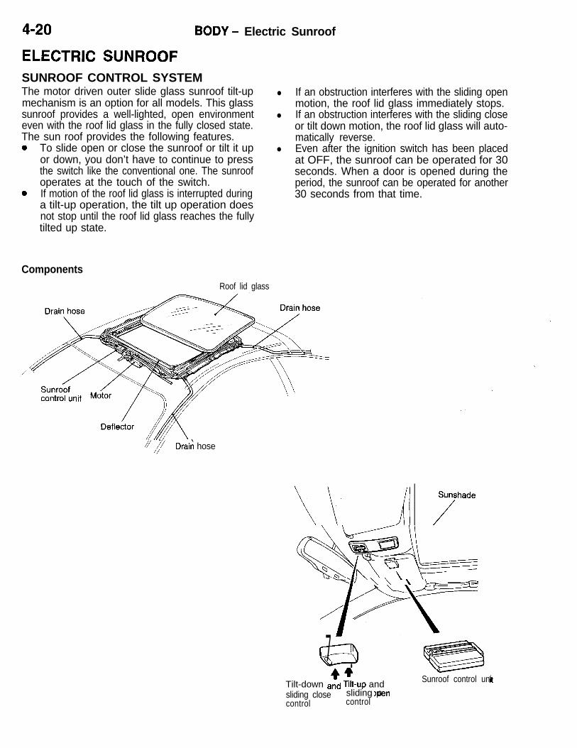
4-20 BODY - Electric Sunroof
l If an obstruction interferes with the sliding openmotion, the roof lid glass immediately stops.
l If an obstruction interferes with the sliding closeor tilt down motion, the roof lid glass will auto-matically reverse.
l Even after the ignition switch has been placedat OFF, the sunroof can be operated for 30seconds. When a door is opened during theperiod, the sunroof can be operated for another30 seconds from that time.
ELECTRIC SUNROOFSUNROOF CONTROL SYSTEMThe motor driven outer slide glass sunroof tilt-upmechanism is an option for all models. This glasssunroof provides a well-lighted, open environmenteven with the roof lid glass in the fully closed state.The sun roof provides the following features.0 To slide open or close the sunroof or tilt it up
or down, you don’t have to continue to pressthe switch like the conventional one. The sunroofoperates at the touch of the switch.
0 If motion of the roof lid glass is interrupted duringa tilt-up operation, the tilt up operation doesnot stop until the roof lid glass reaches the fullytilted up state.
Components
Roof lid glass
/y Draii hose
&WL“‘=-=dJ \\ \ & ?-‘-‘--//lP\c37 .
)pel,Tilt-down a$ x-up and ’
-Sunroof control uni
sliding closecontrol
sliding c -control
18X0705

BODY - Electric Sunroof 4-21
SUNROOF CONTROL UNITThe microcomputer in the sunroof control unit con- The sunroof motor drive circuits, incorporated introls several functions with two different signals (tilt the sunroof control unit, operate under control ofup and sliding open, tilt down and sliding close) the microcomputer.from various points: the sunroof switches, the doorswitch.
System diagram ‘~
Ignition switch
Sunroof control unit-- -- Motor
-W1
t
Dzitch $$
Sunroof switchr -- -- 1 0 1
: Tilt-up, Sliding open 1
Microcomputer
-

4-22 BODY - Electric Sunroof
TILT UP OPERATION(1) When the tilt up switch is pressed for more
than 0.2 seconds, the motor activates.(2) If motion of the roof lid glass is interrupted during
a tilt up operation, the-motor does not stop until ‘dthe roof lid glass reaches the fully tilted up state.
Sunroofswitch
Roof lidglass
Externalforce(load)
0.2 sec. 0.2 sec. 0.2 sec.
UP -OFF -
IDOWN - I I
II
LN ---l-J=*APPLIED-
FREE -
TILT DOWN OPERATION(1) When the tilt-down switch is pressed for more
than 0.2 seconds, the motor activates.(2) If motion of the roof lid glass is interrupted during
a tilt-down operation, the motor reverses andstops after the roof lid is returned to its full upposition.
0.2 sec. 0.2 sec. 0.2 sec.
Sunroofswitch
DOWN -
FULL UP --f-;---+-
TILT UP -
Roof lidglass
TlLTDOWN--- - - - - -
External APPLIED -force(load) FREE -
0.2 sec.0.2 sec.
h
Lj
NOTEFull up position: Where the roof lid glass beginsto slide open
0.2 sec.
Jr,I II I

BODY - Electric Sunroof 4-23
SLIDING OPEN OPERATION (AFTER TILT-UP)
L(1) When the sliding open switch is pressed for (3) The motor can be stopped by pressing the slid-
more than 0.2 seconds, the motor activates. ing close switch even while the roof lid is sliding(2) If movement of the roof lid glass is blocked open.
during the sliding open operation, the motor (4) If the sliding close switch is kept pressed further,will stop immediately. the motor turns in the opposite direction (to
the lid closing direction).
0.2 sec. 0.2 sec.
O P E N -
z&J;gf OFFI
- TTi-I
CLOSE - III
FULLY -w-y-OPEN
Roof lidglass 1
CLOSE -
Externa’ APPLIED -force(load) FREE -
2’sec.
I I i 1 I I--mm - - - -
$L-kT-j- jr
ll-
SLIDING CLOSE OPERATION(1) When the sliding close switch is pressed for
more than 0.2 seconds, the motor activates.(2) If movement of the roof lid glass is blocked
during the sliding close operation, the motor
0.2 sec. 0.2 sec.
O P E N -f$r’ O F F -
CLOSE -l-l
FULLY -I
OPEN
Roof lidglass r
C L O S E - - - - -
External APPLIED -force(load) FREE -
will rotate in the reverse direction by approx.60 mm (2 s/s in,) in terms of the roof lid glassmovement distance before it stops.
- ---Approx. 60 mm (2.38 in.)

4-24 BODY - Electric Sunroof
KEY OFF OPERATION(1) The sunroof can be operated for 30 seconds
after the ignition switch has been set to OFF.In the slide close mode only, however, the motor
30 sec.
Ignition switch ONOFF - f-----j
I
Door switch ON (Opening) -OFF (Closing) -II
0.2 sec. I
II
0.2 sec. I
OPEN -Sunroof switch OFF -
CLOSE - ; II ’
FULLUP - --+-+---
I0.2 sec. ,
II
I I-- --
TILT UP - y..-..-+ S[I _rI;&
TILT DOWN -Roof lid glass I I 1’ I
II, I ’ I
FULLY OPEN - I I- - - - -I I
IC L O S E - - - I - -
can continue until the sunroof reaches the fullyclosed position.
(2) If any of the doors is opened in 30 secondsafter the ignition switch has been placed at OFF,
seconds. In the slide close mode only, however,
the sunroof can be operated for another 30the motor can continue until the sunroof reachesits fully closed position.
ONIgnition switch oFF
30 sec.
-,I30 sec.
- +---I1
Door switchON (Opening) - IOFF (Closing)- I
II
0.2 sec. I
OPEN -Sunroof switch OFF _
CLOSE -
’ IFULLUP - --e--TILTUP - --7-I-
Roof lid glass TILT DOWN - d---I I
F U L L Y O P E N - --+ --l
IC L O S E - ----I
--** t-x$-
17
0 . 2 sec. 1
“ni
1 I
I II
--r;l-
1; 1- - - -I I 1II I
- - . - I - -
--i
I
0.2 sec. 1
z;
; ;---_ ---- -l-I -_--&-3L’ I-ii:--I I
I -’ I
- -

BODY - Electric Sunroof
(3) Once the sunroof reaches its fully closed posi-tion in less than 30 seconds after the ignition
Ignition switch ONOFF -
Door switchON (Opening)-OFF (Closing)-
0.2 sec.
OPEN - 0.2 sec.
Sunroof switch OFF
CLOSE - w
FULLUP - -- ;TILT UP -
Roof lid glass TILT DOWN - --I’ I
FULLY OPEN - - I - -
CLOSE
switch has been placed at OFF, the sunrdofI
can no longer be operated.
kso sec.
1 1
I-30 sec.
cl
0.2 sec.
J--t)
0.2 sec.
--Ih- --- - I I\ - -
-+I
I- --Ah
--l 1I 1 --- --

44;

EXTERIORCONTENTS
DOOR MIRRORS . ......................................... 3
GENERAL DESCRIPTION . ............................ 2
Features . ........................................................ 2
5-I
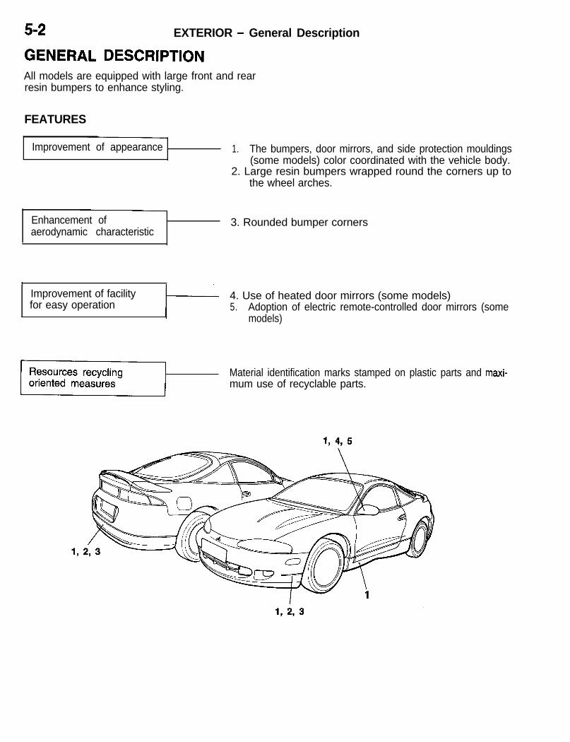
5-2 EXTERIOR - General Description
GENERAL DESCRIPTIONAll models are equipped with large front and rearresin bumpers to enhance styling.
FEATURES
Improvement of appearance 1. The bumpers, door mirrors, and side protection mouldings(some models) color coordinated with the vehicle body.
2. Large resin bumpers wrapped round the corners up tothe wheel arches.
Enhancement ofaerodynamic characteristic
3. Rounded bumper corners
,Improvement of facilityfor easy operation
4. Use of heated door mirrors (some models)5. Adoption of electric remote-controlled door mirrors (some
models)
Material identification marks stamped on plastic parts and maxi- dmum use of recyclable parts.

EXTERIOR - Door Mirrors 5-3
DOOR MIRRORSThe large-size Talbot mirrors are attached on thefront doors that smoothly blend into the body styling.They also contribute to the reduced aerodynamicdrag, and offer the following features:l The mirrors can be either manually remote-con-
trolled or electric remote-controlled dependingon the model.
Electric remote
* Heated door mirrors are available on some mod-els (mirror defogger). This function is performedtogether with the rear window defogger functionby operating the rear window defogger switch.The mirror defoggers are controlled by the sametimer that controls the rear window defogger.
Printed therm0 wires


6-l
INTERIORCONTENTS
INSIDE REAR VIEW MIRROR WITHREADING LAMP . . . . . . . . . . . . . . . . . . . . . . . . . . 10
INSTRUMENT PANEL ANDFLOOR CONSOLE BOX . . . . . . . . . . . . . . . . . . . . 3
LUGGAGE COMPARTMENT FLOOR . . . . . . . 10
SEAT . . . . . . . . . . . . . . . . . . . . . . . . . . . . . . . . . . . . . . 4Construction and Operation . . . . . . . . . . . . . . . . . . . . 5Front seat . . . . . . . . . . . . . . . . . . . . . . . . . . . . . . . . . . . . 4Power seat . . . . . . . . . . . . . . . . . . . . . . . . . . . . . . . . . . . 7Rear seat . . . . . . . . . . . . . . . . . . . . . . . . . . . . . . . . . . . . .
SEAT BELTS . . . . . . . . . . . . . . . . . . . . . . . . . . . . . . 8
SUMMARY OF INTERIOR PARTS . . . . . . . . . . . 2
Features . . . . . . . . . . . . . . . . . . . . . . . . . . . . . . . . . . . . . 2
SUPPLEMENTAL RESTRAINT SYSTEM(SW . . . . . . . . . . . . . . . . . . . . . . . . . . . . . . . . . . . . . 11
Air Bag Module . . . . . . . . . . . . . . . . . . . . . . . . . . . . . . 17Clock Spring . . . . . . . . . . . . . . . . . . . . . . . . . . . . . . ..2 8Construction and Operation . . . . . . . . . . . . . . . . . . . 16SRS Connector . . . . . . . . . . . . . . . . . . . . . . . . . . . . . . 26SRS Diagnostic Unit . . . . . . . . . . . . . . . . . . . . . . . . . 22SRS Schematic . . . . . . . . . . . . . . . . . . . . . . . . . . . . . . 12SRS Warning Light . . . . . . . . . . . . . . . . . . . . . . . . . . 30
Warning/Caution Labels . . . . . . . . . . . . . . . . . . . , . . 13

6-2 INTERIOR - Summary of Interior Parts
SUMMARY OF INTERIOR PARTSThe interior parts are designed to create a senseof high quality while attaching great importance tothe vehicle’s function, comfort and safety.
Also, they reflect our attitude getting active in protec-tion of global environment and recycling of re-sources.
FEATURES
Improved quality feelingI
1. Fully trimmed cabin2. Flowing, integral type instrument panel3. Integral head lining
Greater ease of handling 1. Large glove box2. Cup holders
Convenient accommodationspace for small articles
Ample accommodation space in instrument panel, floor con-sole, door, luggage compartment, etc.
Greater safety 1. Instrument panel padding #i)2. Three-point seat belt with ELR (driver’s side)/Three-point
seat belt with ELR and ALR (passenger’s side and rearseat)
3. Flame-retardant material for upholstery covering and pad-ding (urethane pad.)
4. Installation of air bag module for front seat passenger
Provision for optimumdriving position
1. One-touch pushbutton type adjustable shoulder anchor2. Seat cushion using high-elasticity urethane pad to allow
long driving with little fatigue3. Dual height control mechanism4. Power seat (3-way adjustment)
1. Stamping of material names on plastic parts2. Use of CFC-free sheet urethane3. Use of recyclable material for sound insulating pads

INTERIOR - Instrument Panel and Floor Console Box 6-3
INSTRUMENT PANEL AND FLOOR CONSOLE BOXThe flowing instrument panel provides the feelingof a cockpit. It has the following characteristics.l The instrument panel surface has been covered
with a soft pad to enhance the safety and thesense of quality.
l The center console has been tilted toward thedriver’s seat to provide the driver with improvedcontrol and visibility of the console.
l A large glove box with a sunglass holder hasbeen adopted.
l To offer more convenience, the floor consolehas been provided with two cup holders whichcan be stored inside the console.
l On some models, the floor console lid has beencovered with a soft pad to serve as an armrest.
l An air bag module has been installed in theupper part of the instrument panel on the frontpassenger’s side.
l The resin parts have been stamped with theirmaterial names to facilitate recycling.
CUD holder
Floor console box
Glove box

6-4 INTERIOR - Seat
SEATFRONT SEATThe front seats are designed around the body’scenter of gravity. The driver’s seat has beenequipped with various adjustment mechanisms(7-way adjustments at maximum) to best fit the driv-er’s physical features and riding posture. On somemodels, optional power seats with three-way adjust-
ment mechanisms, namely, power-driven dualheight adjustment mechanisms and slide adjustmentmechanism are available. In addition, use of Freonin urethane pad manufacturing process has beensuspended in an effort to protect the global environ-ment.
Items
Dual heightadjustment
Front heightadjustment
Rear heightadjustment
Driver’s seat Front passenger’s seat
Manual seat Power seat Manual seatI
X
X
X (power)
X (power)I
Slide adjustment X X (power) X
Reclining adjustment
Lumbar support adjustment
X (with memory)
X*
X (with memory)
X
X (with walk-inmechanism)
Side support adjustment
Head restraint vertical adjustment
NOTE: * indicates the item available on some models.
X* X
X X X
<Front passenger’s seat>
vertical adjustment<Driver’s power seat>
<Driver’s manual seat> Head restraint
Lumbar supportvertical adjustment
. /
1CiAd CII Innrr.4- ~ /‘\ U”,“U Ull”‘;: / , -
E2$-A&JQ )\ a---@----- \w( / Z$rt2n t
“LIISlide adjustment F-
Dual heightadjustment
Power seat switch
Slide adjustment1 b
r Slide aajustment

INTERIOR - Seat 6-5
Power Seat Circuit
POWER SEAT SWITCH I
FUSIBLE LINK @
POWER SEAT ASSEMBLI
SLIDE FRONT HEIGHT REAR HEIGHT
I T T T rl
SLIDE MOTOR
) OFF OFF-.IN O N
Memory lever d: 1
FRONT HEIGHTM O T O R
ll,pOFFIN
UP
REAR HEIGHTM O T O R
,>OFF OFF%,IN O N
I
1
CONSTRUCTION AND OPERATIONRECLINING ADJUSTMENT MECHANISM WITH MEMORYIf the seatback is raised after being inclined to the front, itcan be returned to the original angle set in memory by previouslysetting the seatback angle in memory.Furthermore, even after it is reclined at any angle, if the seatbackis raised after being inclined to the front, it can be returnedto the original angle set in memory.
The reclining memory mechanism consists of a memory lever,memory plate, guide plate, guide lever and spring.(1) Set the seatback to the position to be memorized, and
push the memory lever.

6-6 INTERIOR - Seat
I
Memory lever4 ’
Guide lever
Guideplate
Guide lever\
bide plate
Memory range A
(2) When the memory lever is pushed, it releases the meshingof the memory plate and memory lever, and the memoryplate is rotated by the spring force and contacts the guideplate.When the memory lever is released, the lever engageswith the memory plate, completing the memorizing opera-tion.
(3) Pull the reclining adjuster lever and fold the seatback for-ward.
(4) Raise the seatback.As the guide lever is now held by the guide plate, thereclining gear cannot be locked.
(5) Raise the seatback furtherThen the memory plate contacts the position A of the guideplate and the guide plate starts to rotate.When the memorized position is reached, the guide platereleases the guide lever and the reclining gear is lockedto hold the seatback in position.
(6) The memory range is between A and 6 in the illustration.If the memory lever is operated at a position betweenB and C, position 6 is memorized.

INTERIOR - Seat 6-7
Worm aear B Slide adjustment switcl-.-----a---
Limit .ywq
Lower rail
-
Cable wire
POWER SEATSlide Adjustment StructureThe motor, limit switch and gears are mounted on the platefixed to the lower rails.When the slide adjustment switch is operated, the motor startsand rotates worm gear A in the gear box via the cable wire.This rotating torque is transmitted through gears A and B toworm gear B. The worm gear B moves the upper rails andtherefore the seat mounted on the upper rails.When the seat slides to the forward or backward limit, thecover mounted to the upper rail pushes the limit switch andturns the motor off. This stops the seat slide operation.
Front Height and Rear Height Adjusting StructureThe front and rear portions of the seat cushion canbe raised and lowered independently. If the frontheight and rear height switch is pushed to the upside, motor revolutions will be transferred to gearto sector gear. Since the sector gear, shaft and armare fixed, the seat cushion rises continuously (step-less) along with the revolution of the sector gear.
Sector gear Rear height motor
a Arm \ Front height motor
: cushion
As the seat cushion continues to rise, the claw onthe shaft turns the limit switch from ON to OFF,cutting off power to the motor and stopping it.In addition, if the front height and rear height switchis pushed to the down side, operation is reversedwith the motor revolving in the opposite directionand lowering the seat cushion.
When raising front height
When raising rear height
/!&.=I
When raisiyg front and rear height
<Raising> <Lowering>
Seat cushion/
Power seat switch ‘+“.
,.f-----.
,
Limit switch
Seat yshion
Power seat switch
Limit switch Arm
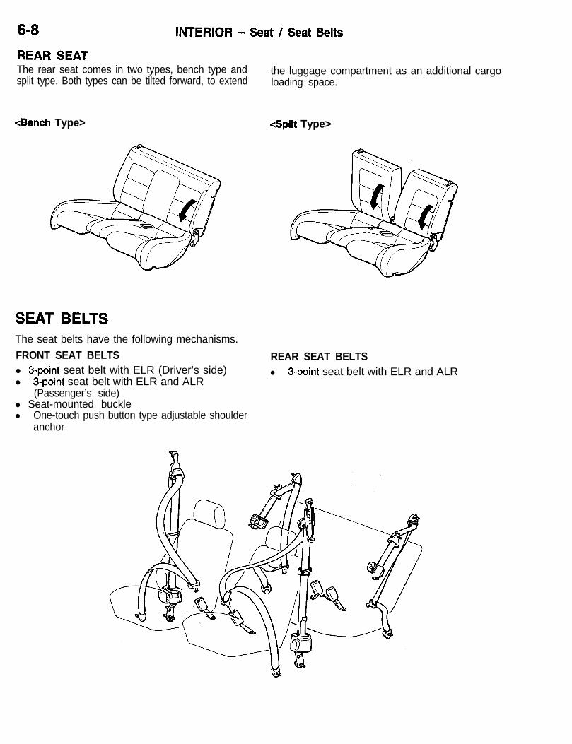
6-8 INTERIOR - Seat / Seat Belts
REAR SEATThe rear seat comes in two types, bench type andsplit type. Both types can be tilted forward, to extend
the luggage compartment as an additional cargoloading space.
<Bench Type> <Split Type>
SEAT BELTSThe seat belts have the following mechanisms.FRONT SEAT BELTSl 3-point seat belt with ELR (Driver’s side)l 3-point seat belt with ELR and ALR
(Passenger’s side)l Seat-mounted bucklel One-touch push button type adjustable shoulder
anchor
REAR SEAT BELTSl 3-point seat belt with ELR and ALR

INTERIOR - Seat Belts 6-9
Guide
Locked(Pushbutton released)
Adjuster rail4
Inward Forward
ONE-TOUCH PUSHBUlTON TYPE ADJUSTABLESHOULDER BELT ANCHORThe mechanism allows adjustment of shoulder belt anchorheight in five stages depending with the physique of the frontseat occupant. It consists of an adjuster rail, a slider and apushbutton provided on the seat belt sash guide.The adjuster rail is secured to the center pillar and providedwith five holes in which the lock pin of the slider may fit.The slider is so assembled to the adjuster rail that it maymove up and down along the rail. The lock pin is providedin the slider to secure the slider in place.The lock pin is always kept pressed to the rail by spring. De-pressing the pushbutton against on the seat belt sash guidewill push the ring out of the sash guide. Then, the lever insidethe slider is pushed to lift the lock pin until the pin is disengagedfrom the adjuster rail, making the slider movable up and down.Each lock pin hole of the adjuster rail is provided with a guidein the upward direction only so that the upward movementof the seat belt anchor can be made without depressing thepushbutton, improving the operability.
Unlocked(Pushbutton depressed)
Lever
Pushbutton
Ring
Lock pin
CONSTRUCTION AND OPERATION OF THE BUCKLEThere is a spring installed in the portion connecting the buckleto the arm, allowing the buckle to tilt forward and inward sothat the belts can be tight enough around the body.

6-10 INTERIOR -Inside Rear View Mirror with Reading Lamp /Luggage Compartment Floor
Inside rear view mirror
LX
Reading lamps
Rear side trim RH
INSIDE REAR VIEW MIRROR WITHREADING LAMPVehicles with power sunroof have been provided with an insiderear view mirror with reading lamps.
LUGGAGE COMPARTMENT FLOOR
For greater convenience in loading and unloading the sparewheel or other articles, the luggage compartment floor boardis hinged at the front, and its rear end can be held raisedwith a hook. A box on the left side under the luggage compart-
” ment floor board may be used to hold small articles. A luggagecompartment side box is located in the R.H. side of the rearside trim. In addition, a cargo net has been provided insidethe luggage compartment to prevent cargo from shifting duringvehicle operation, as well as to offer more convenience tothe user.
Luggage compahment side box Iid \\

INTERIOR - Supplemental Restraint System (SRS) 6-11
i
SUPPLEMENTAL RESTRAINT SYSTEM (SRS)The Supplemental Restraint System (SRS) is de-signed to supplement the front seat belts to helpreduce the risk or severlty of injury to the front seatoccupants by activating and deploying two air bagsduring certain frontal collisions.The SRS consists of: left front and right front impactsensors (located on the right and left front shieldplate); air bag modules for the driver (located inthe center of the steering wheel) and for the frontseat passenger (located above the glove box). Eachmodule contains a folded air bag and an inflatorunit. The SRS also contains: an SRS DiagnosticUnit (SDU) with safing impact sensor (located underthe floor console assembly); and SRS warning lightto indicate the operational status of the SRS (locatedon the instrument panel); clock spring (mountedbehind the steering wheel); and wiring.
The SRS is designed so that the air bags will deploywhen the safing sensor, plus either or both of theleft front and right front impact sensors simulta-neously activate while the ignition switch is in theON position. These sensors are designed to acti-vated in frontal or near-frontal impacts of moderateto server force.Only authorized service personnel should work onor around SRS components. Those personnelshould read this manual carefully before startingsuch work. Extreme care must be used when servic-ing the SRS to avoid injury to service personnel(by inadvertent deployment of the air bags) or vehicleoccupant (by rendering the SRS inoperative).
VEHICLEIDENTIFICATIONCODE CHARTPLATE
Front impactsensor (R.H.)E.59
-LL SRS warning light\ L---
Air bag module (Passenger’s side)
I ClockSRS diagnostic uni:(SDU)(with built-in safingimpact sensor)

6-12 INTERIOR - Supplemental Restraint System (SRS)
SRS SCHEMATIC
IGNITION SWITCH<ST>
_IjFF -
Connector lock switch
r Park/Neutralposition switch
Combinationmeter (SRSwarning light)
Gl>
13 Multi-purposefuses
SDU- - - -
1
w EEP Battery r? L,rrROM voltage L,
detection VI (1
t _circuit
0 A I DConverter Condenser
I! 1!t 4
voltagedetectioncircuit
I - [
SafingSquib 4: : II impactresistance + sensordetection ,circuit c
I1:
Impact sensorresistancedetectioncircuit
I I4
I II1 I
!. t 1%Ll““6C /
Microcomputer
-lScan toolinterfacecircuit
- - - - - -
1---__
I ’41
0 j,I-- AC3
Clockspring
/.--- -- -l&FOFFY
ON
Data link connector(For scan tool)
Front impact Front impactsensor (L.H.) sensor (R.H.)
Air bagmodule
Air bagmodule
(Passenger’s (Driver’s side)side)

INTERIOR - Supplemental Restraint System (SRS) 643WARNING/CAUTION LABELSA number of caution labels relating to the SRS arefound in the vehicle, as shown in the following il-lustration. Follow label instructions when servicingSRS.
A l--l sus-1\ ’ 1p --j-P‘fyy I
)CDJ[F+2i~\7zr;-J ----\-‘Ir7‘
/ \
If labels are dirty or damaged, replace them withnew ones.

INTERIOR - Supplemental Restraint System (SRS)
A.
B,
C
WARNINGThis vehicle has an air bag system.Refer to service manual before servicing or dis-assembling underhood components. Read“SRS” section of manual for important instruc-tions.Improper service procedures can result in theair bag firing or becoming inoperative, possiblyleading to injury.
CAUTIONThis vehicle has air bags for front occupantsas a supplemental restraint system (SRS).You must always wear your seatbelt, even withan air bag:Air bags are not designed to inflate in rolloversor in rear, side or low-speed frontal crashed.Air bags inflate powerfully and in a moment.If you’re too close to an inflating air bag, it couldseriously injure you. Seatbelts help keep youin position for air bag inflation in a crash. Aninflating air bag can seriously injure small chil-dren. A child in a rear-facing child restraint canbe badly injured by an inflating air bag, so neveruse a rear-facing child restraint in the front seatof this vehicle: a rear-facing child restraint shouldbe used only in the rear seat. Use a forward-fac-ing child restraint with the front passenger seatas far back as possible, or in the rear seat.Before driving read label inside the glove box;if the “SRS” light comes on while you are driving,or does not come on when you first start thevehicles, see your dealer for service.
Driver’s air bag informationThis vehicle has an air bag which will supple-ment the seatbelt in certain frontal collisions.The air bag is not a substitute for the seatbeltin any type of collision. The driver, and all otheroccupants, should wear seatbelts at all times.WARNING!If the “SRS” warning light does not illuminateFor several seconds when ignition key is turnedto “ON” or the engine is started, or if the warninglight stays on while driving, take the vehicleto your nearest authorized dealer immediately.Also if the vehicle’s front end is damaged orif the air bag has deployed.Take the vehicle for service immediately.The air bag system must be inspected by anauthorized dealer ten years after the vehiclerna~~f~ct~ra date shown on the certification la-bel located cn the left front door-latch post or
D.
Read the “SRS” section of your owner’s manualbefore driving, for important information, aboutoperation, and service of the air bag system.When you are going to discard your gas genera-tor or vehicle, please see your MITSUBISHIdealer.
CAUTION: SRS diagnostic unitThis unit cannot be repaired.If defective, remove and replace entire unit perservice manual instructions.Do not disassemble or tamper.See service manual for handling and storageinstructions.Do not drop: keep dry.Failure to follow instructions could render airbag inoperative and result in driver injury.
E. 1 CAUTION: SRS
F.
G.
Before replacing steering wheel, read servicemanual, center front wheels and align SRS clockspring neutral marks.Failure to do so may render SRS system inop-erative, risking serious driver injury.
DANGER POISONKeep out of the reach of children.Contains sodium azide and potassium nitratecontents are poisonous and extremely flam-mable. Contact with acid, water, or heavy metalsmay produce harmful and irritating gases otexplosive compounds. Do not dismantle, incin-erate, bring into contact with electricity or storeat temperatures exceeding 93°C (200°F).FIRST AID: If contents are swallowed inducevomiting. For eye contact flush eye with waterfor 15 minutes. If gases from acid or water con-tact are inhaled, seek fresh air. In every case,get prompt medical attention.For additional information, see material safetydata sheet (MSDS) for this product.
CAUTION: SRS clock springThis is not a repairable part. Do not disassembleor tamper.If defective, remove and replace entire unit perservice manual instructions.Before replacement, read service manual, tenter front wheels and align neutral marks.Failure to follow instructions may render SRSsystem inoperative, risking serious driver injury

INTERIOR - Supplemental Restraint System (SRS) 6-15
H.
L
CAUTION: SRSBefore removal of steering gear box, read ser-vice manual, center front wheels and removeignition key.Failure to do so may damage SRS clock springand render SRS system inoperative, risking seri-ous driver injury.
I. WARNING: SRSThis air bag module cannot be repaired. Donot disassemble or tamper.Do not perform diagnosis. Do not touch withelectrical test equipment or probes.Refer to service manual for further instructions,and for special hadling.Storage and disposal procedures. Tamperingor mishandling can result in injury.DANGER POISONKeep out of the reach of children.Contains sodium azide and potassium nitratecontents are poisonous and extremely flam-mable. Contact with acid, water or heavy metalsmay produce harmful and irritating gases orexplosive compounds. Do not dismantle. Incin-erate, bring into contact with electricity or storeat temperatures exceeding 93°C (200°F).FIRST AID:If contents are swallowed induce vomiting. Foreye contact flush eye with water for 15 minutes.If cases from acid or water contact are inhaled,seek fresh air. In every case, get prompt medicalattention.

6-16 INTERIOR - Supplemental Restraint System (SRS)
CONSTRUCTION AND OPERATIONIMPACT SENSORSThere are 2 different types of sensors used; 2 front built in the SRS diagnosis unit. The right and leftimpact sensors and safing impact sensor. One frontimpact sensor is provided in each of the right and
front impact sensors are connected in parallel.
left shield pla?e, and one safing impact sensor isThe front impact sensors are connected in serieswith the safing impact sensor.
Safing impactsensor (Incorporatedin SRS diagnostic unit)
Air bagmodule<Driver’s side>
Front impactsensor (L.H.)
Frompower supply -----)
<Passenger’s side> Front impactsensor (R.H.)
If a front-end collision causes either of the frontimpact sensors and the safing impact sensor tobe simultaneously “ON”, the air bag will deploy.They are constructed as shown below and containa G sensor each.The front and safing impact sensors are essentiallyidentical in construction.The G sensor consists of a moving contact whichis a roll spring wound around a roller, a fixed contactpositioned in its moving direction, consisting of abase, a metallic case, etc. If an impact greater thanpreset is applied in the direction of the arrow shownin the illustration, the inertial force causes the roller
Front impact sensor Safing impact sensor
Roller
Fixed
to rotate and move, so that contacts are broughtinto the ON stage. To maintain a high measureof G sensor reliability, the contacts have been goldplated and the metallic case charged with an inactivegas. dEach impact sensor contains a resistor connectedin parallel with the contacts for detection of a faultin the wiring. The SRS diagnosis unit always sup-plies a very small amount of current to the sensorcircuit to monitor a change in the circuit resistance.CautionMake sure that the impact sensors are neverdisassembled.
Roller
\ Moving contact
Fixed contact

INTERIOR - Supplemental Restraint System (SRS) 6-17
Hinge portionof pad cover
d\e Inflator
AIR BAG MODULE<Driver’s side>The air bag module is an assembly part comprising of anair bag, pad cover, inflator, and parts for securing them. Itis provided at the center of the steering wheel.CautionMake sure that the air bag is never disassembled.
Section A - A
e : Pad cover deploying direction13R0694
Air bagThe air bag is made of a nylon cloth with a rubbercoating inside. It is accommodated in the pad atthe center of the steering wheel together with theinflator.The air bag is inflated by the nitrogen gas fromthe inflator. The load of the driver pressed against
Pad coverThe pad cover is made from urethane. When theair bag deploys, the crease is broken, allowing theair bag to move out and deploy with the hinge por-tions as its fulcrums. The pad cover has a net, etc.
Groove portionPad cover
/ Groove oortion
‘Air bag
Inflator
Section B - B
the air bag by the impact causes the nitrogen gasto escape through the two exhaust holes made onthe rear, and the deflation helps lessen the impact.
insert-molded except for the crease to prevent theair bag from being broken as it deploys, and alsoto prevent broken pieces from scattering around.

648 INTERIOR - Sutwlemental Restraint System (SRS)
InflatorThe inflator consists of a squib, igniter, gas gener-ants, diffuser screen, etc. contained in an aluminumcontainer. It is mounted in the air bag module hous-ing.The bottom of the inflator is provided with an electri-cal connection to which an ignition current is sup-plied. If current is supplied to the squib, a smallamount of explosive in the squib is burnt causingthe igniter to burn, and the resultant heat burnsthe gas generants. Combustion of the generants
rapidly produces nitrogen gas which is forcedthrough the diffuser screen into the air bag. Thediffuser screen serves as a filter to remove cindersand also helps cool down the gas temperature andreduce the gas generation noise. A shorting pinis provided in the connector portion of the squib.Whenever the air bag module is removed, the short-ing pin makes a short circuit across the terminalsto prevent flow of current caused by static electricityto the squib.
DiffuserIgniter
\
Gas generantI
To air bag \ / To air bag/////////- -
Connecto?lock \ Sq\uib B&e
Shorting clip
Diffuser screen
e : Nitrogen gasc : Flame

INTERIOR - Supplemental Restraint System (SW) 6-19<Passenger’s side>The air bag module consists of an air bag, module cover,inflator, and parts for securing them. It is provided above theglove box.CautionMake sure that the air bag is never disassembled.
Module cover
Lock /
Air bagThe air bag, made of nylon cloth lined with rubbercoating, is housed together with the inflator, underthe module cover provided above the glove box.The air bag is inflated with nitrogen gas generatedby the inflator. Then, as the front passenger hits
Module coverThe module cover has aluminum sheet and urethaneformed into a unit. It is normally closed by hardrubber type locks on both the sides.When the air bag is deployed, the hard rubber typelock is broken, allowing the module cover to turn
the air bag, the gas is discharged from the twoexhaust holes, one on each side, deflating the airbag to reduce the impact on the passenger.
on the hinge provided at the upper part, open upwardand let the air bag out to be inflated.

6-20 INTERIOR - Supplemental Restraint System (SRS)
InflatorThe inflator has a squib, ignition cord (fuse), primingpowder, gas generator, filter, etc. put in an aluminumcontainer and is installed inside the air bag module.On one side of the inflator is the harness throughwhich an ignition current flows. When the currentflowing through the harness reaches the squib, asmall quantity of powder is burned to ignite theignition cord. The cord burns the priming powderand the generated heat causes the gas generator
to burn. Combusion of the gas generator producesnitorogen gas quickly, which is sent to the insideof the air bag through the filter.
d
The filter eliminates cinders, lowers the gas tempera-ture and reduce the gas generator noise.The inflator has a shorting clip provided at the con-nector of the squib harness in the same manneras the driver’s side inflator.
Harness Ignition cord (fuse) Filter Priming powder
Sqbib IGas generant
Air bag deployment [in case of 50 km/h (30 mph) frontalimpact](1) OPERATION FOR APPROXIMATELY 15 MILLISECONDS
AFTER THE COLLISIONIf a strong impact produced by a collision is detected byeither of the front impact sensors and the safing impact sensor in approximately 10 milliseconds after the collision,the SRS diagnostic unit will supply an ignition signal tothe squib.In approximately 3 milliseconds after the ignition signalhas been supplied to the squib, gas generation will begin.

INTERIOR - Supplemental Restraint System (SRS) 6-21
J
(2) In approximately 20 milliseconds after the collision, theair bag folded in the pad cover will begin to inflate, thepad cover will break at its crease, and the air bag willexpand outward.
(3) In approximately 35 milliseconds after the collision, theinflated air bag will touch the chest of the driver.
(4) In approximately 40 milliseconds after the collision, theair bag will be fully inflated.
(5) In approximately 55 milliseconds after the collision, thepressure of the driver against the air bag causes the gasto escape through the two exhaust holes on the rear ofthe module, and the deflation helps lessen the impact im-posed on the driver.
(6) In approximately 105 milliseconds after the collision, theair bag that has absorbed the impact will rapidly deflate,providing visibility for the driver.

6-22 INTERIOR - SuDdemental Restraint System (SRSI
SRS DIAGNOSTIC UNITThe SRS diagnostic unit monitors the impact sen-sors, squib, wiring harness, condensers, battery volt-age etc. If it detects a problem, it illuminates the“SRS” warning light to alert the driver. It also storesin memory what the problem is, and the durationof the problem (the duration during which the warn-ing light stayed ON).The condensers provided in the diagnostic unit accu-mulate electric energy during the period the ignition
switch is ON. This supplies squib ignition current,even if the power cable from the battery is brokenby the collision, to inflate the air bag as soon asthe front impact sensor and safing impact sensorare simultaneously switched ON.CautionMake sure that the SRS diagnostic unit is neverdisassembled.
1. Monitoring functionThe SRS diagnostic unit monitors the wiring harness and SRScomponents shown in the following table to check whetherthey satisfy the specified values. When the ignition key is in“ON” or “START” position, the SRS warning light should illumi-nate for about 7 seconds and then turn off.This indicates that the SRS system is in operational order.If the SRS warning light does any of the following, immediateinspection is needed.(1) The SRS warning light does not illuminate as described
above.(2) The SRS warning light stays on for more than 7 seconds.(3) The SRS warning light illuminates while driving.The fault data is stored in terms of a diagnostic code in thenon-volatile memory (EEPROM)*. The duration of the faultis also stored in terms of the ON duration of the warning light.
Component
Front impact sensor
Air bag module (Driver’s side)
Air bag module (Passenger’s side)
Condenser
Cranking detection circuit
Main Monitoring Point
Short circuit
Open-circuit once
Open-circuit twice
Short circuit
Open circuit
Short circuit
Open circuit
Terminal voltage high
Terminal voltage low
Cranking signal detection time
Diagnostic Code No.
11
12
13
21
22
24
25
31
32
3 3 ”a

INTERIOR - Supplemental Restraint System (SRS) 6-23
I Component Main Monitoring Point Diagnostic Code No.
Double lock connector Unlock or lock switch open-circuited 34**
41**Battery
IGl voltage low (Multi-purpose fuse No. 4 is blown)
IGl voltage low (Multi-purpose fuse No. 8 is blown) 42**
External circuit open-circuited or short-circuited 43**SRS warning light
Drive circuit defective 44
SRS diagnostic unit
NOTE* EEPROM = Electrically Erasable Programmable ROMA ROM to which data can be stored and be electrically written and from which data can be electrically erased.**: Equipped. with the automatic diagnosis code erasure function. (Refer to P.6-25)

6-24 INTERIOR - Supplemental Restraint System (SRS)
2. Supplying squib ignition energyThe energy for ignition of the squib is supplied by two circuits;the battery of the vehicle and the condensers.Even if the Dower voltage to the SRS diagnostic unit is lost.
Ignition switch <ST>I I
Multi-purposefuse
yr DC-DCconverter
L,vlL1 ()
,
Safingimpactsensor
the ignition capability is-retained by the condensers for morethan 0.5 seconds.(1) The two independent battery power supplies (from fuses
4 and 8) are connected via diodes in the diagnostic unit.If the voltage is larger than 9V between the connectorterminal of the unit and the ground, the squib can be ignited.
(2) The IGl voltage is boosted to about 25V by the DC-DCconverter to provide more in reserve than the low limitvoltage mentioned above in charging the condensers thatsupply the ignition energy.
Caution1. When the SRS is to be repaired or parts to be replaced,
make sure that the negative (-) cable of the batteryis disconnected beforehand for insulation.After the negative (-) cable of the battery has beendisconnected, wait for more than 60 seconds beforemaking any service attempt.The condensers in the SRS diagnostic unit retain fora given period the voltage necessary for inflating theair bag even after removal of the battery voltage.lf aservice attempt is made during the period, accidentalinflation could cause serious personal injury.
2. Do not measure the resistance across the terminalsof the SRS diagnostic unit. Do not directly touch thetest probe to any of the terminals.Even if an attempt is made to measure the resistance,no correct value can be obtained because of the effectsof internal circuits. In addition, there is a danger ofdamage to the gold plated portion of the terminals.
<Passen- <Driver’sFron:‘zpact se::; igz side>
\ v /Air bag module

INTERIOR - Supplemental Restraint System (SRS) 6-25
Data to be stored
Faults
Fault duration
Number of timesmemory canbe erased
Description
All faults stored indiagnostic codes
The period the warninglight is ON is integrated inminutes.(Maximum stored period:9999 minutes S 7 days)
The number of times thediagnostic codes and faultdurations have beenerased by a scan tool is in-tegrated.(Maximum number oftimes to be stored: 250)
3. Diagnostic functionFault diagnosis continues to be performed during the periodthe ignition switch is ON except during cranking. If a faultis detected, the SRS warning light is lit.The microcomputer determines a diagnostic code on the basisof the results of measurements by various measuring circuitsand stores it in “EEPROM”.The fault duration (the period the warning light has been ON)is integrated in increments of a minute and stored in the EE-PROM together with the diagnostic code. The stored data canbe read and erased by a scan tool. The number of times thememory has been erased by a scan tool is stored in the “EE-PROM” to provide reference information on the past servicehistory. The data can be read by a scan tool in the sameway as the fault durations.
NOTEOnce a fault is detected, the SRS warning light continuesto light, even if normal operation of the system is restored,until the diagnostic code is erased.
4. Automatic diagnostic code erasure functionThe automatic diagnostic code erasure function operatesaccording to the indicated diagnostic code No. (Refer toP.6-22). Once the malfunction location that causes a diag-nostic code to be displayed returns to the normal condition,if the malfunction reoccurs continuously at 5-second inter-vals, the appropriate malfunction code can be erased. Atthis time, if all other diagnostic codes have been erased,the SRS warning light will switch off and the intermittentdurations of the malfunction will also be erased automatical-ly. In this case, the erasure is not included in the numberof times erased.NOTEIf the A/D converter inside the SRS diagnostic unit is mal-functioning, diagnostic codes No. 41, 42 and 43 will notbe erased by the automatic diagnostic code erasure func-tion. Furthermore, during cranking, none of the codes willbe erased by this function.

6-26 INTERIOR - Supplemental Restraint System (SRS)
UNLOCKED LOCKED
Secondarv lock lever
Connecternotch Lock sprmg
Harness sideconnector
Primary lock/
Improperly fitted stateForced down
SRS diagnosticunit side connector
Secondarylock leverprojection
lonnector -xojection ,-
Properly fitted state
Lock springPrimary lock
!'
SRS CONNECTORThe connector of the SRS diagnostic unit has a double lockmechanism, fit verification mechanism and connector shortingmechanism.
DOUBLE LOCK MECHANISMThe mechanism is composed of two mechanisms: each connec-tor of the SRS diagnostic unit is locked to the connector ofthe harness, then these connectors (of the four harnesses)are locked with the secondary lock lever mounted on the con-nector of the SRS diagnostic unit side.The secondary lock lever locking is done as the lock springfits in the notch of the connector. The operating principle isdescribed below.
When Connectors are to be Fitted(1) The SRS diagnostic unit and harness side connectors are
fitted. (Primary lock)(2) The secondary lock lever mounted to the SRS diagnostic
unit side connector is pressed down by finger until a click ’vjis heard indicating that the connectors have been locked.(Secondary lock)If the harness and SRS diagnostic unit connectors do notproperly fit, the secondary lock lever side projection andthe harness side connector projection interfere with eachother, making it impossible to lock the connectors.
When Connectors are Unlocked(1) Press in the lock spring with a flat tip (-) screwdriver to
disengage the lock spring from the notch area of the connec-tor, and release the lock (secondary lock) of the secondarylock lever.CautionForced removal of the connector without releasingthe secondary lock lever will result in a damaged locklever.
(2) Press the primary lock of each of the harness side connec-tors and remove the harness side connector.

INTERIOR - Supplemental Restraint System (SRS) 6-27
Short bar
Secondarylock lever
iarness side connector
Pressed down (Press-fitted terminal
Short bar
To body wiring Press-fitted tab terminalsharness (2-pin) I\
Short terminal (open)
connector t
Short terminal
connector termin
L
FIT VERIFICATION MECHANISMThe mechanism is used to electrically check the engagementof the connector between the SRS diagnostic unit and thebody wiring harness. The operating principle is described below.(1) Securely connect the SRS diagnostic unit and harness
side connectors and press the secondary lock lever downto lock the connectors.
(2) At this time, the short bar provided on the rear surfaceof the secondary lock lever produces a short circuit acrossterminals No. 7 and 8 of the SRS diagnostic unit. TheSRS diagnostic unit supplies monitoring current to the circuitto electrically verify that the connectors have been locked.
CONNECTOR SHORTING MECHANISMThe mechanism is designed for prevention of accidental explo-sion of the inflator when the clock spring connector (for thesquib circuit) is removed from the SRS diagnostic unit. Theoperating principle is described below.
When Connectors are FittedWhen the SRS diagnostic unit and clock spring connector arecoupled, the circuit between the short terminals and clock springconnector terminals are kept in the OFF state by the partitionplate provided in the connector of the SRS diagnostic unit.
When Connectors are DisconnectedWhen the clock spring connectors are disconnected from theSRS diagnostic unit, the partition plate between the short termi-nals and clock spring connector terminals is removed. As aresult, a short circuit is formed between the two poles of theclock spring connector terminals to prevent generation of apotential difference (current) between the squib terminals.
I

6-28 INTERIOR - Supplemental Restraint System (SRS)
CLOCK SPRINGThe clock spring is provided between the steeringwheel (air bag module) and column switch body(steering column).The clock spring provides harness connections be-tween the air bag module and SRS diagnostic unit,between the horn switch and dashboard wiring har-ness, and between the remote control switch anddashboard wiring harness.The clock spring consists of a neutral position indica-tion mechanism, flat cable, upper case, lower case,rotor, etc.The flat cable is loosely wound like a coil, and isheld in the upper and lower cases with one of its
ends mounted to the rotor and the other endmounted to the upper case. The upper and lowercases are mounted to the steering column. Therotor is coupled with. the steering shaft. Rotationof the steering wheel (steering shaft) causes therotor to rotate. Accordingly, the flat cable is woundround the rotor or loosened, and operates with therotor as the steering wheel is turned.CautionMake sure that the clock spring is never disas-sembled.
Flat
\ Lower caseUV- Anti-vibration sheet
Cable end support
Steering wheelAir bag module
Body To air bag moduleI
wiring / ._harness
2 horn
To ciuise control switch
Q ‘--,&Gnostic u n i t
When steering whe!el is inneutral position(straight ahead position)
FlatIWhen steering wheel isturned clockwise
cover
When steering wheel isturned counter-clockwise ,
Rotor
Flat cable- wUpper cover
'
Uppercover

INTERIOR - Supplemental Restraint System (SRS) 6-29NEUTRAL POSITION INDICATION MECHANISMThe system consists of a ring gear (number of teeth:90) provided in the upper case, a transparent covermounted on the rotor with screws, and a gear (num-ber of teeth: 80) which is in mesh with the ringgear and is driven by the convex portion of thecover.The upper case is mounted on the steering columnand is always held in position.The rotor coupled with the steering shaft and alwaysoperates with the steering wheel. The gear is alwayskept in mesh with the ring gear by the convex portionof the cover. If the rotor turns through a rotation,the convex portion of the cover also turns througha rotation. So the gear is displaced in the opposite
direction to the rotating direction of the rotor bythe difference in the number of teeth between thegear and ring gear or by 10 teeth.Markings R2, 1, NEUTRAL, 1, and 2L are madeon the gear for every IO teeth. An alignment markis made on the upper case. The clock spring isplaced in the neutral (straight ahead) position bylining up the alignment mark with the mark NEU-TRAL of the gear. The mark “R” on the gear indicatesthat the rotor has been turned clockwise, whereasthe mark “L” indicates counterclockwise rotation ofthe rotor.How the gear operates when the rotor is turnedone rotation clockwise
iiB Cover
Upper case k
Alignment hark
How the clear‘operates when the rotor is turned
wkr
Iear
’ Ring gear
one rotaiion ciockwiseAlignment A quarter of a rotation Half a rotation
Gear d&e portion Gear A rotation

6-30 INTERIOR - Supplemental Restraint System (SRS)
warninglight
Ignition switch
To SRS diagnosis unit
SRS WARNING LIGHTThe SRS warning light is provided at the left side of the combina-tion meter.When the SRS is in good order, the light should illuminatefor approximately 7 seconds after the ignition key has beenturned ON, or the engine has been started, and will then goout.The SRS warning light has only one display area but containstwo lights. Even if one of the lights is defective, the other onecan be lit.The SRS warning light is checked by the SRS diagnostic unitfor defective light.

EQUIPMENT
BATTERY . . . . . . . . . . . . . . . . . . . . . . . . . . . . . . . . . . 5Specifications . . . . . . . . . . . . . . . . . . . . . . . . . . . . . . . . . 5
COMBINATION METERS . . . . . . . . . . . . . . . . . . . 11Electric Type Speedometer . . . . . . . . . . . . . . . . . . . 12Meters and Gauges . . . . . . . . . . . . . . . . . . . . . . . . . . 11Vehicle Speed Sensor . . . . . . . . . . . . . . . . . . . . . . . . 12
CONTENTS
ETACS . . . . . . . . . . . . . . . . . . . . . . . . . . . . . . . . . . . 17Functions and Summary of Operation . . . . . . . . . 17Input Check Facility of ETACS . . . . . . . . . . . . . . . . 29Operation . . . . . . . . . . . . . . . . . . . . . . . . . . . . . . . . . . . 20
Parts and Funcitons Related with ETACS . . . . . . 29
FEATURES . . . . . . . . . . . . . . . . . . . . . . . . . . . . . . . . 2
HEATER AND AIR CONDITIONING . . . . . . . . . 31A/C Functional Components List . . . . . . . . . . . . . . 35Auto Compressor-ECM . . . . . . . . . . . . . . . . . . . . . . . 36Compressor . . . . . . . . . . . . . . . . . . . . . . . . . . . . . . . ..3 7Condenser Fan and Radiator Fan Control . . . . . 40Construction Diagram . . . . . . . . . . . . . . . . . . . . . . . . 32Features . . . . . . . . . . . . . . . . . . . . . . . . . . . . . . . . . . . . 31Reciever . . . . . . . . . . . . . . . . . . . . . . . . . . . . . . . . . . ..4 0
Refrigerant Temperature Switch <Turbo> . . . . . . . 36Service Valve.. . . . . . . . . . . . . . . . . . . . . . . . . . . . . . .4 0Specifications . . . . . . . . . . . . . . . . . . . . . . . . . . . . . . . . 31
IGNITION SWITCH . . . . . . . . . . . . . . . . . . . . . . . . . 6Ignition Key Push Type Double-action IgnitionSwitch <M/T> . . . . . . . . . . . . . . . . . . . . . . . . . . . . . . . . . 6Operation . . . . . . . . . . . . . . . . . . . . . . . . . . . . . . . . . . . . 7
LIGHTING . . . . . . . . . . . . . . . . . . . . . . . . . . . . . . . . . 6Headlight . . . . . . . . . . . . . . . . . . . . . . . . . . . . . . . . . . . . . 9Specifications . . . . . . . . . . . . . . . . . . . . . . . . . . . . . . . . . 8
ON-BOARD DIAGNOSTIC SYSTEM . . . . . . . . . 3Data Link Connectors . . . . . . . . . . . . . . . . . . . . . . . . . 4
RADIO AND TAPE PLAYER,CD PLAYER, CD AUTO CHANGER,SPEAKER, ANTENNA . . . . . . . . . . . . . . . . . . . . . 15
THEFT-ALARM SYSTEM . . . . . . . . . . . . . . . . . . . 30
WIPERS AND WASHERS . . . . . . . . . . . . . . . . . . 13Rear Wiper and Washer . . . . . . . . . . . . . . . . . . . . . . 14Windshield Wipers and Washers . . . . . . . . . . . . . . 13

7-2 EQUIPMENT - Features
FEATURES
Improved reliability 1. Gold plating of electronic control system terminals d2. MWP (Multipole Water Proof type) connector
Improved visibilityand safety
1. Double action ignition switch (ignition key push type)adopted to prevent locking the steering wheel during drivingby accidentally removing the ignition key <M/T vehicles>
2. Large-sized combination meter adopted3. High-mounted stop light used.4. Multi-reflector type headlights adopted.
Improved usability andconvenience
1. ETACS adopted for centralized control of the alarm buzzerand timer functions
2. Electric type speedometer whose pointer moves smoothlywithout vibrations as the speed changes
Improved serviceability 1. Data link connectors (centralized terminals for inspection)adopted to allow inspection of the diagnostic functionsby a scan tool
2. Dedicated connectors for adjustment of ignition timing,>d
engine speed detection and fuel pump operation checkadopted
3. Plug-in type combination meter easy to mount and demountadopted
4. Wiper motor and link system removable as a unit.

EQUIPMENT - On-board Dignostic System 7-3
ON-BOARD DIGNOSTIC SYSTEMThe on-board diagnostic system comprises the fol-lowing functions to assure better serviceability.
Diagnostic troublecode (low speedsignal) output
0
Diagnostic troublecode (high speedsignal) output
0
Service data(high speed signal)output
0
Actuator test(low speed signal)
Actuator test(high speed signal) 0
Simplified inspectioncode output (Sameindication pattern asfor diagnosis code)
Diagnostic troublecode retained inmemory
ELC-4A/T Auto-cruisecontrol
0 0
0
0/
0Until battery is OFF
ABS
FWD AWD
0
0
0
0
0
0
SRS
0
0*EEPROM
Diagnostic troublecode erased by 0 0 0 0 0scan tool

7-4 EQUIPMENT - On-board Dignostic System
DATA L I N K CONNECTORSData link connectors (centralized terminals for in-spection) have been adopted to allow inspectionof the diagnosis functions by the scan tool.
Data link connector (12 pin)
Data link connector (12 pin)
21. -
g: 124. -25. SCI Eng. RX*’26. -27. CCD Bus (+)*2;;. CCD Bus (-)*2
. -
;:: z32. -
Data link connector (16 pin)
1 2 3 4 5 6 7 8
9 10 11 12 13 14 15 16I-J
Data link connector (J1962-16 pin)1. Diagnosis control
g’ I4: Chassis around5. Signal gr&nd6. ELC-4A/T7. 9141 -K*3/SCI-2 TX*’8. ABS (AWD)9. ETACS (One shot pulse signal)
10. -
::* SRS13: Auto-cruise control14. Simulated vehicles speed15. -16. Battery power supply (+B)
NOTE*l: Non-turbo*2: Vehicles with F4ACl automatic transaxle*s: Engine (MFI), ABS (FWD)

EQUIPMENT - Battery 7-5
BATTERYi The battery of the following specifications has been
established.
SPECIFICATIONS
Items Specifications
Type B.C.I. Group size 86 B.C.I. Group size 86Capacity (5HR) Ah 50 50Reserve capacity min. 90 90Cold cranking current A 430 525

7-6 EQUIPMENT - Ignition Switch
IGNITION SWITCHThe ignition key push type double-action ignitionswitch is installed that prevents the steering wheelfrom being locked up as a result of the ignition keybeing inadvertently removed from the key cylinderwhile the vehicle is in motion. This contributes togreater safety.For additional convenience, an ignition switch illu-mination light has been adopted which is lit at night
for approximately 10 seconds by the timer functionof the ETACS-ECU so that the ignition key can be deasily inserted.NOTEFor the timer function of the ignition switch illumina-tion light, refer to the section on the ETACS-ECUon P.7-23.
IGNITION KEY PUSH TYPE DOUBLE-ACTION IGNITION SWITCH <M/T>A double-action lever has been provided in the steer-ing lock cylinder, and a raceway for orbital motionof the double-action lever and an ACC position stop-per provided in the key cylinder to make sure that
the ignition key cannot be removed unless the driverrotates it to the LOCK position, while pushing thekey in.
/Key cylinder ACC position stopper

EQUIPMENT - Ignition Switch 7-7
Double-actionlever
Key cylinder ACC positionstopper
Steering lock Double-action
/
- -
1
\Key cylinderACC positionstopper
Raceway
OPERATIONWith the ignition key not pushed in (at the ACC position)The key cylinder is locked by the double-action lever pressedagainst the ACC position stopper. Therefore, the ignition keycannot be rotated from the ACC position to the LOCK position.
With the ignition key pushed in (at the ACC position)The key cylinder is forced into the steering lock cylinder, andthe double-action lever is moved away from the ACC positionstopper. The double-action lever can now move along the race-way, so the ignition key can be rotated to the LOCK position.
i
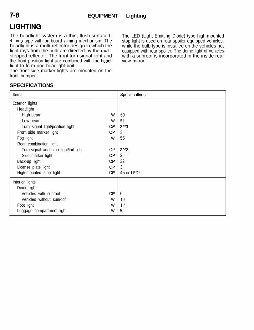
EQUIPMENT - Lighting
LIGHTINGThe headlight system is a thin, flush-surfaced,4-lamp type with on-board aiming mechanism. Theheadlight is a multi-reflector design in which thelight rays from the bulb are directed by the multi-stepped reflector. The front turn signal light andthe front position light are combined with the head-light to form one headlight unit.The front side marker lights are mounted on thefront bumper.
The LED (Light Emitting Diode) type high-mountedstop light is used on rear spoiler equipped vehicles,while the bulb type is installed on the vehicles notequipped with rear spoiler. The dome light of vehicleswith a sunroof is incorporated in the inside rearview mirror.
SPECIFICATIONS
cItems
Exterior lightsHeadlight
High-beamLow-beamTurn signal light/position light
Front side marker lightFog lightRear combination light
Turn-signal and stop light/tail lightSide marker light
Back-up lightLicense plate lightHigh-mounted stop light
W 60W 51
CP 3213CP 3W 55
CP 3212CP 2CP 32CP 3CP 45 or LED*
Interior lightsDome light
Vehicles with sunroofVehicles without sunroof
Foot lightLuggage compartment light
CPWWW
6101.45

EQUIPMENT - Lighting 7-9
Dome light(Vehicles with sunroof)
\Dome light(Vehicles without sunroof)
Headlight (front turnsignal and front \ /position light)
\
-Y/
Fog lightFront side markerlight
Foot lightFoot light. \
HEADLIGHTON-BOARD AIMING MECHANISMThe vertical aiming adjustment can be made byturning the vertical adjusting screw to bring thebubble of the vertical adjusting gauge to the positionbetween the adjusting marks.
High-mounted stop light
(bulb ty?
<Vertical adjusting>
\\.Arc* _
4-kAdjusting mark,
light
Rear combination lightBack-up light
The horizontal aiming adjustment can be accom-plished by turning the horizontal adjusting screwto align the “0” mark of the gear (B) with the lineof the stopper and that of the headlight housing.
:Horizontal adjusting>
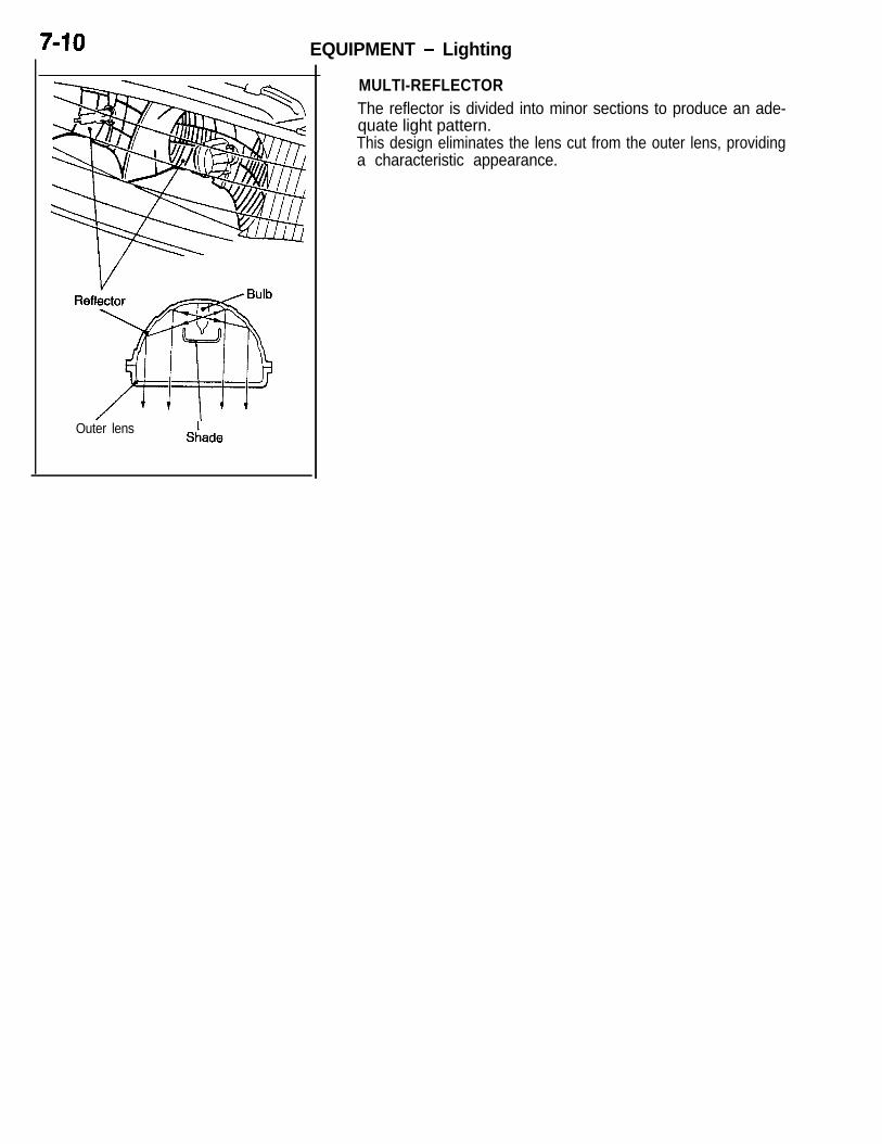
EQUIPMENT - Lighting
Outer lensShade
MULTI-REFLECTORThe reflector is divided into minor sections to produce an ade-quate light pattern.This design eliminates the lens cut from the outer lens, providing da characteristic appearance.

EQUIPMENT - Combination Meters 7-11
COMBINATION METERSi METERS AND GAUGES
The combination meter is of the plug-in type to facili- The speedometer is an electric type speedometertate its removal and installation. It is also a pointer whose pointer moves smoothly without vibrationstype to provide good visibility. in response to a pulse signal from the vehicle speedThe combination meter has large speedometer and sensor as the speed changes.tachometer located in the middle, with the fuel gauge,engine coolant temperature gauge, boost gauge, NOTE
and oil pressure gauge on both sides. The indicator lamps and warning lamps vary ondifferent models.
<Turbo>
i
i
<Non-turbo>
Vehicles withautomatic transaxle
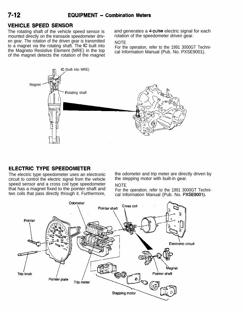
7-12 EQUIPMENT - Combination Meters
VEHICLE SPEED SENSORThe rotating shaft of the vehicle speed sensor ismounted directly on the transaxle speedometer driv-en gear. The rotation of the driven gear is transmittedto a magnet via the rotating shaft. The IC built intothe Magneto Resistive Element (MRE) in the topof the magnet detects the rotation of the magnet
and generates a 4-pulse electric signal for eachrotation of the speedometer driven gear. #LjNOTEFor the operation, refer to the 1991 3000GT Techni-cal Information Manual (Pub. No. PXSE9001).
(built into MRE)
Magnet
Rotating shaft
ELECTRIC TYPE SPEEDOMETERThe electric type speedometer uses an electroniccircuit to control the electric signal from the vehiclespeed sensor and a cross coil type speedometerthat has a magnet fixed to the pointer shaft andtwo coils that pass directly through it. Furthermore,
the odometer and trip meter are directly driven bythe stepping motor with built-in gear.NOTEFor the operation, refer to the 1991 3000GT Techni-cal Information Manual (Pub. No. PXSE9001).

EQUIPMENT - WiDers and Washers f-1 3_I
WIPERS AND WASHERSi WINDSHIELD WIPERS AND WASHERS
The windshield wiper comes in two types; two speed e The washer nozzle is a 2-nozzle, 4-jet type.type with fixed interval intermittent function, and l The windshield washer tank is installed in thetwo speed type with variable intermittent function. L.H. side of the engine compartment on non-tur-They have the following characteristics. bo vehicles and in the R.H. side of the luggagel The wiper motor and links are mounted as a compartment on turbo vehicles.
unit on a frame to enhance the serviceability.l A washer interlocked wiper function and mist
wiper function have been adopted for greaterconvenience.
<Turbo>
Frame
WindshieldWiper blade Wiper arm washer
I I tank
Nozzle Link
Washer hose
<Non-turbo>
\Alinmr hlzarin WiPer arm Link
Frime INozzle
Winbshieldwashertank
Washer hose

7-I 4 EQUIPMENT - Wipers and Washers
REAR WIPER AND WASHERThe rear wiper has an intermittent wiper functionfor better rear visibility in the event of a light rain.
compartment. On turbo vehicles, the windshieldwasher tank is also used as a rear washer tank.
It offers the following features. l The washer is one-nozzle, two-jet type.d
l On non-turbo vehicles, the rear washer tankis installed in the L.H. side of the luggage
<Turbo>Washer nozzle
Wash& hose w--7-Washer tank
motor
<Non-turbo>
Washer nozzle
/ Wiper blade
Wiper arm
/
/Washer hose
motor
Washer tank
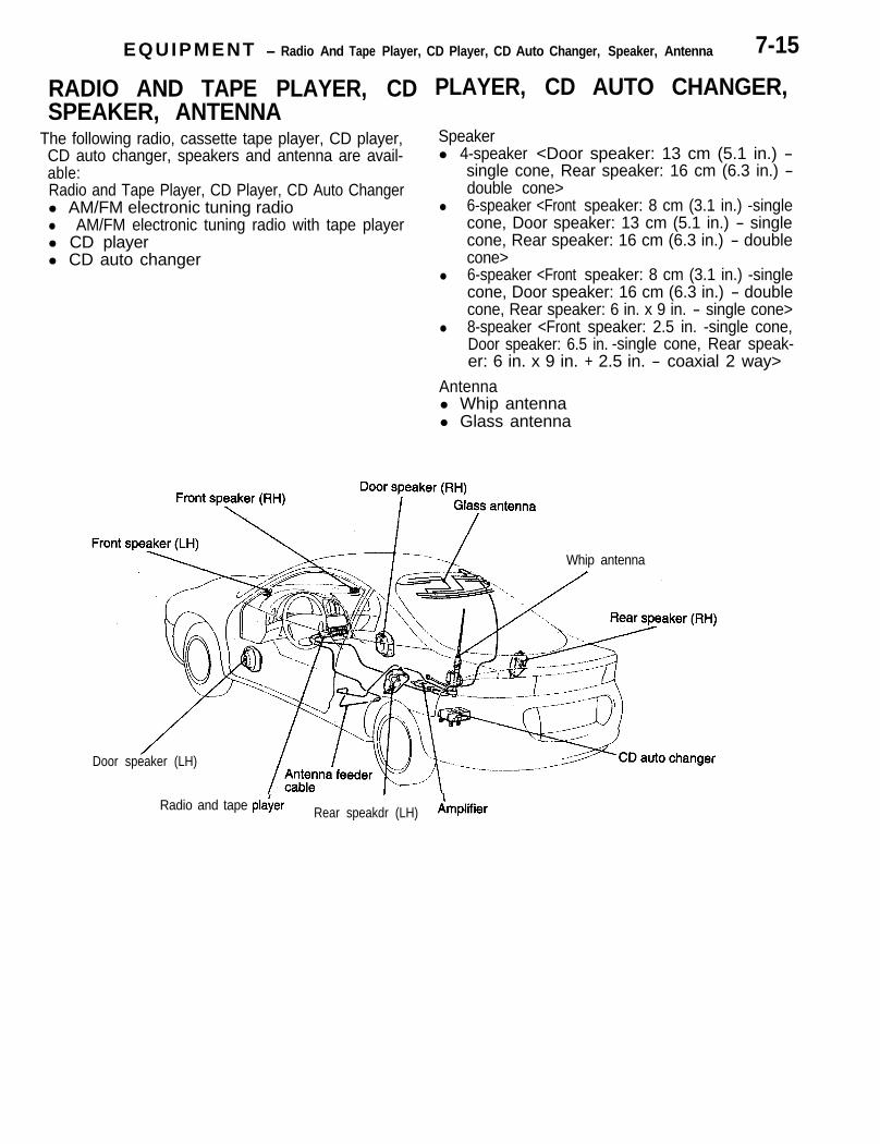
EQUIPMENT - Radio And Tape Player, CD Player, CD Auto Changer, Speaker, Antenna 7-15
RADIO AND TAPE PLAYER, CDSPEAKER, ANTENNA
LJ The following radio, cassette tape player, CD player,CD auto changer, speakers and antenna are avail-able:Radio and Tape Player, CD Player, CD Auto Changerl AM/FM electronic tuning radiol AM/FM electronic tuning radio with tape playerl CD playerl CD auto changer
PLAYER, CD AUTO CHANGER,
Speakerl 4-speaker <Door speaker: 13 cm (5.1 in.) -
single cone, Rear speaker: 16 cm (6.3 in.) -double cone>
l 6-speaker <Front speaker: 8 cm (3.1 in.) -singlecone, Door speaker: 13 cm (5.1 in.) - singlecone, Rear speaker: 16 cm (6.3 in.) - doublecone>
l 6-speaker <Front speaker: 8 cm (3.1 in.) -singlecone, Door speaker: 16 cm (6.3 in.) - doublecone, Rear speaker: 6 in. x 9 in. - single cone>
l 8-speaker <Front speaker: 2.5 in. -single cone,Door speaker: 6.5 in. -single cone, Rear speak-er: 6 in. x 9 in. + 2.5 in. - coaxial 2 way>
Antennal Whip antennal Glass antenna
Whip antenna
Door speaker (LH)
Radio and tape plaier Rear speakdr (LH) Amplifier

7-16 EQUIPMENT - Radio And Tape Player, CD Player, CD Auto Changer, Speaker, Antenna
<AM/FM Electronic Tuning Radio> <AM/FM Electronic Tuning Radio andTape Player>
<AM/FM Electronic Tuning Radio andTape Players
<AM/FM Electronic Tuning Radio andTape Player with Equalizer>

EQUIPMENT - ETACS 7-17
ETACSThe ETACS (Electronic Time and Alarm Control System) hasbeen adopted for centralized control of various timer and alarmfunctions.The ETACS control unit has an input check function whichmakes it possible to easily check whether the circuit from theinput switch to the microprocessor in the control unit is function-ing properly or not.
FUNCTIONS AND SUMMARY OF OPERATION
Item
Light reminder alarmfunction
Function and Summary of Operation
When the ignition key is removedfrom the ignition switch and the Lighting switch
driver’s door is opened while the %F -lighting switch is ON (PARKING orHEAD), the buzzer will sound con- Ignition switch
tinuously to remind the driver that OOPF Jthe lights are ON. Driver’s door
switch ON (open)OFF (closed) r
Buzzer outputO N:;;;;;; xds.J ~-~
not sound.) OFF
Ignition key remindertimer function
To prevent accidental door lockingwith the key still in the ignition, thefollowing will take place. If the driv-er’s door is opened, and the driveror passenger lock knob is operated,the system will automatically re-lease the lock.NOTEThis function has priority over thecentral door lock system function.
Keyreminderswitch
gJF -
;fgh odN:gyd) I
Door lock LOCKyyor fjjr2cK n
(ON)
ifgygk gf$cK-/W-U
n n(ON)
;;;;WW ;pp 1Fg-j ff5 sec. 5 sec. 5 sec.
Ignition key reminderalarm function
When the driver’s door is openedwithout removing the ignition key(OFF or ACC position), the buzzerwill sound intermittently to remindthat the ignition key has not beenremoved.
ignition switch g:ForACC d
lb&minder($y removed)
(Key inserted) nO F F
Driver’s door (Open) ONswitch (Closed) OFF 7
(Buzzer sounds.)O N
Buzzer output (Buzzer doesnot sound.) OFF

7-18 EQUIPMENT - ETACS
Item Function and Summary of Operation
Ignition switch illu- When the driver’s seat door ismination light timer opened with the ignition switch infunction the OFF or ACC position, the igni-
tion switch illumination light will lightignition switch g# or ACC 1
I
for approximately 10 seconds soDriver’s door ON (open)
Ithat the ignition key can be easily switch OFF (closed) _ nr J-Linserted even at night. However, if Ithe ignition key is placed in the ONposition within the 1 O-second inter-val, the ignition switch illumination
%mer output(Light OFF) 10 sets. 10 sets. 10 sets.
light will go out immediately.
Dome light and footlight dimming timerfunction
When all the doors and tailgate are Ignition switch
closed with the dome light switch in :;ForACC I
the door interlocked position (ve-hicles with sunroof) or OFF (ve-hicles without sunroof) and with the Door switch,
ignition switch in the OFF or ACCliftgate switch”, ON (open)lwwe mmpafiment OFF (c losed) i;
position, the dome light and foot light switch**l-l
light will slowly dim, and will go outin approximately six seconds. -Y
When the ignition switch is in the Timer output(Light ON) ON(Light OFF) OFF
‘\ \
ON position, however, no dimming4PTE
F+ Dimming interval
operation will be performed. approx. 6 seconds
@Vehicles with theft-alarm system.Vehicles without theft-alarm system.
Defogger timer func-tion
When the defogger switch is turnedON with the ignition switch in theON position, the defogger will oper-ate for 11 minutes.If the defogger switch is pressedagain during the 11 -minute interval,however, the defogger will stop op-erating,
ignition switch
Defogger switch
Timer output
:PFm
EF_J-L_nn_n__
::F -11 minutes 11 minutes 11 minutes

EQUIPMENT - ETACS 7-19
Item Function and Summary of Operation
Seat belt warning tim-er fuction<Warning light> When the ignition key is turned on, ignition O N
switch I - - - - - - -the seat belt warning light flashes
O F F
for 6 seconds (4 times). H signal
Timer output &r!r~N) I
(Light OFF)-p+=+6 s e c . ----t
<Buzzer> If the driver’s seat belt is not wornwhen the ignition switch is turned tothe ON position, the buzzer soundsintermittently for six seconds, urg-ing the driver to wear the seat belt.
Ignition switch ::,n
;.egpswtich ru
Timer output
Central door lock timer When the driver’s door is locked byfunction means of its key or inside lock Door lock
knob, all doors can be locked. actuator (LH) $pF) Al
With the driver’s door unlocked, un-locking for the second time bymeans of the key unlocks all other
Door lockkey cylinder
doors. switch (LH) :ruu
Timer output
LK J&l--Fi
Power window timerfunction
When the ignition key is turned off,the ETACS timer function is acti-vated, and the power window canbe opened and closed using thepower window switch for 30 se-conds.The power window timer stops,however, if a door or liftgate isopened within 30 seconds.
Ignitionswitch EFDoor switch,liftgate switch”‘, OFF (closed)kmaw ON (open)compartmentlight switch*2
ON ’Trmer ++J--$%
OFF , j--output 30 sec. 30 sec.
!jPTE
l 2 1Vehicles with theft-alarm system.Vehicles without theft-alarm system.

EQUIPMENT - ETACS
OPERATIONLIGHT REMINDER ALARM FUNCTION1. When the lighting switch is in the ON (TAIL
or HEAD) position, the tail light relay is in theON state, so the H signal from the tail lightis input to AND2.
2. When the ignition switch is in the OFF position,the H signal of the ignition switch inverted byNOT1 is input to AND,.
3. As a result, when the driver’s door is opened(door switch ON), the H signal of the door switchinverted by NOT2 is input to ANDl. Then AND1outputs H signal.
Fusible linkI
Tail lightrelay
---_ON
--cm
-
To taillight
I
4. When the H signal output from AND1 is inputto AND2, the signal output from AND2 alsochanges to H signal which operates the detectorcircuit. Then the buzzer output causes the tran-sistor to be ON, and the buzzer sounds continu-ously to remind the driver that the lights (taillights or headlights) are ON.
NOTEIf the ignition key is left inserted with the ignitionswitch in the OFF position, even if the conditionsfor the light reminder function hold good, the buzzerwill sound intermittently, as the ignition key reminderalarm function takes precedence.
Ignition switch (IGl)
-T-
Buzzer h!l rNOT
5v
AND
3 1 JANDz
Ignitionswitch
1 Buzzer &zzer s o u n d s ; ’
LJDriver’sdoornwitch
(0pened)ON - - I(Closed) OFF
output ( B u z z e r d o e s _] Ll ULnot sound) OFF
ETACS-ECU
_--_ElilFi nt-F Driver’s door’ ‘..-. switch
ON n#1 :
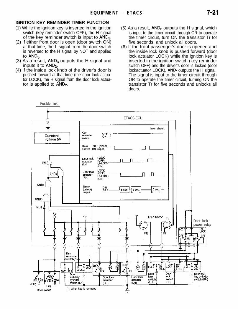
EQUIPMENT - ETACS 7-21IGNITION KEY REMINDER TIMER FUNCTION
LJ
(1) While the ignition key is inserted in the ignitionswitch (key reminder switch OFF), the H signalof the key reminder switch is input to ANDs.
(2) If either front door is open (door switch ON)at that time, the L signal from the door switchis reversed to the H signal by NOT and appliedto AND3.
(3) As a result, AND3 outputs the H signal andinputs it to AND2.
(4) If the inside lock knob of the driver’s door ispushed forward at that time (the door lock actua-tor LOCK), the H signal from the door lock actua-tor is applied to AND2.
(5) As a result, AND2 outputs the H signal, whichis input to the timer circuit through OR to operatethe timer circuit, turn ON the transistor Tr forfive seconds, and unlock all doors.
(6) If the front passenger’s door is opened andthe inside lock knob is pushed forward (doorlock actuator LOCK) while the ignition key isinserted in the ignition switch (key reminderswitch OFF) and the driver’s door is locked (doorlockactuator LOCK), AND, outputs the H signal.The signal is input to the timer circuit throughOR to operate the timer circuit, turning ON thetransistor Tr for five seconds and unlocks alldoors.
Fusible linkI
A ETACS-ECUV
Keyreminderswitch
limer circuit
gJF,
DoorOFF @‘Osed) Iswitch ON (open)
Timer(unlock)output
O NO F F
\/ \I
Door lockpower relay

EQUIPMENT - ETACS
IGNITION KEY REMINDER ALARM FUNCTION1. When the ignition key is left inserted with the
ignition switch in the OFF or ACC position, theH signals of the key reminder switch and theignition switch inverted by NOT1 are input to
by NOT2 and the H signal output from AND1are input to AND2. Then AND2 outputs H signalto cause the detector circuit to operate.
3.ANDi. As a result, AND1 outputs H signal.
The buzzer output causes the transistor to be
2. When the driver’s door is opened (door switchalternately ON and OFF, and the buzzer sounds
ON), the H signal of the door switch invertedintermittently to remind the driver that the ignitionkey has not been removed.
ETACS-EC1
Fusible link Ignition switch (IGl)
3ANDzDetection circuit
8 NOTI
4NDl
Ignitionswitch gFForACC/
Key~w~~~r
(Key removed) ON(Key inserted) OFF
n
Driver’sdoorswitch
Buzzeroutput
(Buzzer sounds)
Driver’s doorswitch
I(Key inserted)
Keyreminderswitch
k( Key removed)=

EQUIPMENT - ETACS
IGNITION SWITCH ILLUMINATION LIGHT TIMER FUNCTION1. When the ignition switch is in the OFF or ACC
position, the H signal of the ignition switch in-verted by NOT, is input to AND, and AND2.
2. When the driver’s door is opened (door switchON), the H signal of the door switch invertedby NOT2 is input to AND,. As a result, AND1outputs H signal to cause the timer circuit tooperate.
3. Accordingly, when the H signal output from thetimer is input to AND2, the output signal fromAND2 changes to H signal which causes thetransistor to be ON for 10 seconds to light theignition switch illumination light.
Ignition switchillumination light
4. When the ignition switch is placed in the ONposition during operation of the timer, the L sig-nal of the ignition switch inverted by NOT, isinput to AND2. As a result, AND2 outputs Lsignal which causes the transistor to be OFF,and the ignition switch illumination light goesout immediately.
NOTEEven if the driver’s door is opened and closed (doorswitch caused to be ON and OFF) while the timeris in operation, no input signal is accepted.
Fusible link Ignition switch (IGl)
ii
4‘(
I
Timer circuitI g n i t i o n O Nswitch OFForACC -
/Driver‘s 1door (Opened) ONswitch ( C l o s e d ) O F F n l-l 1
, II
Timeroutput
H signal (ON)L signal (OFF) 10 sets.
ETACS-ECU
‘E)l, Driver’s door1 q..k~~g~.2~ i switch
T :

7-24 EQUIPMENT - ETACS
DOME LIGHT AND FOOT LIGHT DIMMING TIMER FUNCTION1. When any of the doors or tailgate is opened
(door switch ON or luggage compartment lightswitch* ON) with the dome light switch in theDOOR position (vehicles without sunroof) orOFF position (vehicles with sunroof), the domelight will light ON.NOTEWhen the front doors or tailgate is opened, thefoot light comes on regardless of the light switchposition.
2. When all the doors and tailgate are closed withthe ignition switch in the OFF or ACC position(door switch OFF and luggage compartmentlight switch* OFF), the H signal of the ignitionswitch inverted by NOT and the H signal ofthe door switch are input to AND. As a result,
Fusible linkI
Ignition switch (IGl)I
ETACS-EC1J
r
AND outputs H signal which operates the timercircuit.
3. The timer output provides signals which slowlyreduce the voltage to the transistor in approxi-mately six seconds , thereby dimming the domelight and foot light.
4. When the ignition switch is placed in the ONposition during operation of the timer, the L sig-nal of the ignition switch inverted by NOT isinput to AND. As a result, AND outputs L signal,and the timer circuit stops operation. The domelight and foot light, therefore, goes out immedi-ately without dimming.
NOTE*: On vehicles with theft-alarm system, this switchis the liftgate switch.
-/-JAN:
Ignition switch Timer circuit
EFor ACC/
Door switch(Opened) ON( C l o s e d ) OFFU
;;
Timer output(Light ON)
approx. 6 sets.I - - - - - -
l Transistor
Doorswitch (LH)
fiR
:Dome light
:Without < W i t h ;:iunroof> sunroof>
1Footlight
= or liftgateswitch

EQUIPMENT - ETACS 7-25DEFOGGER TIMER FUNCTION1. When the ignition switch is turned to the ON
position, the H signal of the ignition switch andthe H signal of the constant voltage are inputto AND. As a result, AND outputs H signal.
2. When the defogger switch is placed in the ONposition, the H signal inverted by NOT is inputto timer circuit to activate the timer circuit.
3. Since the defogger switch (auto reset switch)placed in the ON position is automatically resetto the OFF state, the L signal which is oppositeto the signal in Item (2) is input to the timercircuit after the switch has been caused to beON, but the timer keeps on operating.
The timer output causes the transistor to beON for II minutes. The defogger relay is alsoplaced in the ON position to operate the defog-ger.When the ignition switch is placed in the OFFposition or when the defogger switch is placedin the ON position again during operation ofthe timer, the H signal is input to the timer circuitagain. As a result, the timer circuit stops operat-ing, and the transistor is forced to the OFF state.The defogger relay is also placed in the OFFoosition and the defogger stops operating.
Ignition switchWI)
-I-
NOT
Timer circuitIgnition ONswitch OFF m
s”w”&fger g:F a
T i m e r O N moutput OFF -
-1 7
11 mins 11 mins 11 mins
Transistor
OFF3. ON ~;f#c.w
ETACS-ECU
FusiblIgnition switch
le link (iG2)- - -
1 Defoggerrelay
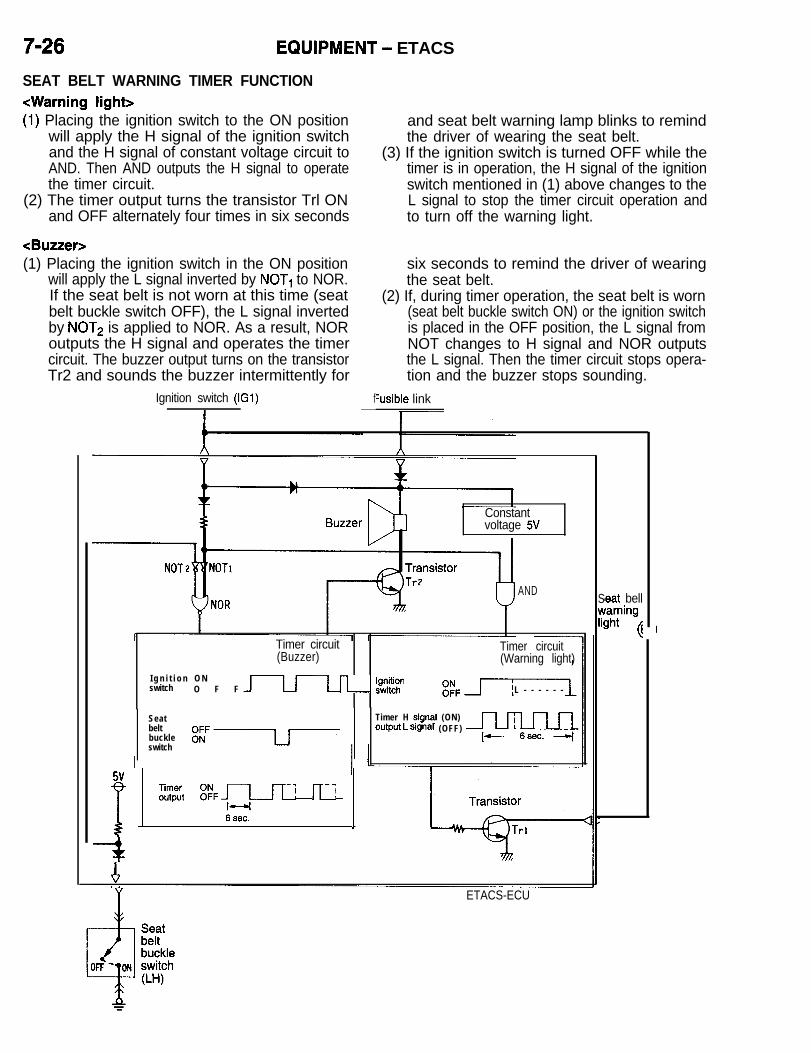
7-26 EQUIPMENT - ETACS
SEAT BELT WARNING TIMER FUNCTION<Warning light>(1) Placing the ignition switch to the ON position
will apply the H signal of the ignition switchand the H signal of constant voltage circuit toAND. Then AND outputs the H signal to operatethe timer circuit.
(2) The timer output turns the transistor Trl ONand OFF alternately four times in six seconds
<Buzzer>(1) Placing the ignition switch in the ON position
will apply the L signal inverted by NOT, to NOR.If the seat belt is not worn at this time (seatbelt buckle switch OFF), the L signal invertedby NOT2 is applied to NOR. As a result, NORoutputs the H signal and operates the timercircuit. The buzzer output turns on the transistorTr2 and sounds the buzzer intermittently for
Ignition switch (IGl) f-
and seat belt warning lamp blinks to remindthe driver of wearing the seat belt.
(3) If the ignition switch is turned OFF while thetimer is in operation, the H signal of the ignitionswitch mentioned in (1) above changes to theL signal to stop the timer circuit operation andto turn off the warning light.
six seconds to remind the driver of wearingthe seat belt.
(2) If, during timer operation, the seat belt is worn(seat belt buckle switch ON) or the ignition switchis placed in the OFF position, the L signal fromNOT changes to H signal and NOR outputsthe L signal. Then the timer circuit stops opera-tion and the buzzer stops sounding.
%sible link
Constantvoltage 5V
AND
Timer circuit(Buzzer)
I g n i t i o n O Nswitch O F F J-u-Ln- 2$2
Timer circuit(Warning light)
L - - - - - -
Seatbeltbuckleswitch
Timer H $gnal (ON)output L sIgnal (OFF) w
f j ::;it :pFp-’ n-1 1
t
SwIi!
1 ETACS-ECU
#eat bellrarningaht
4

EQUIPMENT - ETACS 7-27CENTRAL DOOR LOCK TIMER FUNCTION
/ (1) If the ignition key has already been removedfrom the ignition switch (key reminder switchON), the L signal of the key reminder switchis applied to NAND. Or if all doors have beenclosed (door switches OFF), the H signal ofthe door switch inverted to L by NOT is appliedto NAND.
(2) If the ignition key has been removed from theignition switch or all doors have been closed,NAND outputs the H signal to be applied toAND.
(3) At this time, pushing the inside lock knob ofthe driver’s door forward (door lock actuatorLOCK) will apply the H signal to AND.
(4) As a result, AND outputs the H signal and isinput to the timer circuit through OR to operatethe timer circuit, turning on the transistor Trlfor 0.5 second to lock all doors.
Fusible linkI
NOTEThe door key cylinder and door lock actuator areconnected together by the rod through the doorlatch. When, therefore, the driver’s door is lockedby means of the key, similar operation is accom-plished.(5) When the driver’s door is in the unlocked condi-
tion, the L signal of the door lock actuator isapplied to NOR.
(6) If, in this condition, the unlocking operation ofthe driver’s door using the ignition switch isdone for the second time, the L signal of thedoor lock key cylinder switch is applied to NOR.
(7) As a result, NOR outputs the H signal to NORand outputs it to the timer circuit through ORto operate the timer circuit, turning on the transis-tor Tr2 for 0.5 second to unlock all doors.
IA ETACS-ECU
Y
AN
NOT
OR
L-rTimer circuit 1
Door lockkey cylinderswitch (LH)
;;gt yIcK Jd/=I0.5 sec.
Transistor1 Tr2Tr
1
Door lockpower relay

7-28 EQUIPMENT - ETACS
POWER WINDOW TIMER FUNCTION(1) If the ignition switch is placed in the ON position,
the transistor Trl is turned ON and the powerwindow relay is also turned ON, allowing thepower window to be opened/closed by the powerwindow switch (main or sub switch).
(2) Turning the ignition switch from ON to OFF willturn OFF the transistor Trl. At this time, theignition switch signal inverted by NOT to H isapplied to AND. In addition, when all doors andliftgate are closed, the H signal from the doorswitches and the luggage compartment lightswitch is also applied to AND. Therefore, ANDoutputs the H signal to operate the timer circuit
and turn on the transistor Tr2 for 30 seconds,allowing the window to be opened and closed.
(3) If any door or the liftgate is opened while thetimer is in operation, the L signal from the doorswitch or luggage compartment light switch*is applied to AND. Therefore, AND outputs theL signal to stop operation of the timer circuit.As a result, the transistor Tr2 is turned off, mak-ing it impossible to open and close the window.NOTE*: On vehicles with theft-alarm system, the lug-gage compartment light switch is the liftgateswitch.
Fusible Ignitionlink switch (IGI)
-I- I
Constant Transistorvoltage 5Vi, 1 q sc
NOT Trl
AND I
Timer circuit
Ignitionswitch EfF
Doorswitch ,,OFF (closed)liftgate ON (open)
switch
Timeroutput
YY ETACS-ECU
Luggage compartmentlight switch orliftgate switch
W-0 0-H)) T
Fusiblelink- -
b1IIt f
Power windowmain switch
U-W‘ ” I
Power window motorDoor switch

EQUIPMENT - ETACS
PARTS AND FUNCTIONS RELATED WITH E T A C S
Functions
Door lock actuator*
Door lock power relay
NOTE(1) * mark indicates a switch or sensor that can be used for input inspection with a scan tool or voltmeter.(2) x mark indicates a part relevant for each function.
INPUT CHECK FACILITY OF ETACSThe ETACS-ECU has an input check facility whichenables you to check all the circuits between theindividual switches and the ETACS-ECU on the ba-sis of a change in voltage at the ETACS terminalof the data link connector by use of a scan toolor voltmeter.NOTEFor the location and pin positions of the data linkconnector, refer to P.7-4.
The input check facility of the ETACS includes thefollowing functions.1. Ignition switch2. Door switch3. Defogger switch4. Tail light5. Key reminder switch6. Door lock switch7. Seat belt buckle switch8. Door lock key cylinder switch (LH)9. Liftgate switch

7-30 EQUIPMENT - Theft-alarm System
THEFT-ALARM SYSTEMWhen the door, liftgate or hood locked by the speci-fied procedure is opened without using the key orremote control switch (keyless entry system), thehorn sounds intermittently and the headlights blinkto give visual and audible alarm.Furthermore, the starter circuit is interrupted in sucha way that the engine cannot be started, if the ignitionkey is not used.Note that this system is controlled by the ElectronicControl Unit (ECU) as one function of the ETACS(Electronic Time and Alarm Control System).
The system is composed of the components de-scribed below.NOTEFor arming/disarming the system, activating/deacti-vating the alarm and checking the system operation,refer to the 1991 Model 3000GT Technical Informa-tion Manual (Pub.No.PXSE9001).
Key-reminder switch
Door lock actuator
Theft alarmstarter relay (M/T)
and R.H.)switch

EQUIPMENT - Heater and Air Conditioning 7-31
HEATER AND AIR CONDITIONINGThe heating system is a high-performance and low-noise full-air-mix system that provides a two-layerstratified airflow. It features an independent face-lev-el air flow and cool air by-passing functions.The air conditioning system is essentially the sameas the conventional ones, but they incorporate a
new CFC-free refrigerant (R134a) system that useshydro fluorocarbon (HFC) containing hydrogenatoms as the refrigerant gas to meet the CFC controlregulations that call for protection of the ozone layer.
FEATURES
Improvement in comfort
Protection of globalenvironment
1. Full-air-mix heater providing two-layer stratified air flow.2. Cool air by-passing function capable of sending fresh air
to the face even with the heater unit in operation.3. Independent face-level air flow function capable of sending
air constantly from the side ventilators.4. Scroll type variable delivery air compressor that offers
improved cooling performance and quietness. <Turbo>
Independent face-level air flow from side ventilators.
Adoption of new refrigerant (R134a) system.
1. Adoption of flange fitting design and O-ring slip-off prevent-ing construction for piping joints to improve serviceabilityand reliability.
2. Compressor lock controller for protecting the drive beltwhen compressor is locked. <Non-turbo>
SPECIFICATIONS
ILJ
Item
Heater unitType
Heater control switchCompressor
Model<Turbo><Non-turbo>
Dual pressure switchHigh pressure switchLow pressure switch
Refrigerant and quantity
Specifications
Two-way-flow full-air mix systemDial and lever type
Scroll type cMSC 105 CVS>Inclined-plate type <lOPAl 7C>
kPa (psi)OFF: 3,140 (456) ON: 2,550 (370)OFF: 200 (29) ON: 220 (32)
g (oz.) R134a (HFC-134a), Approx. 700-740 (24.69-26.10)
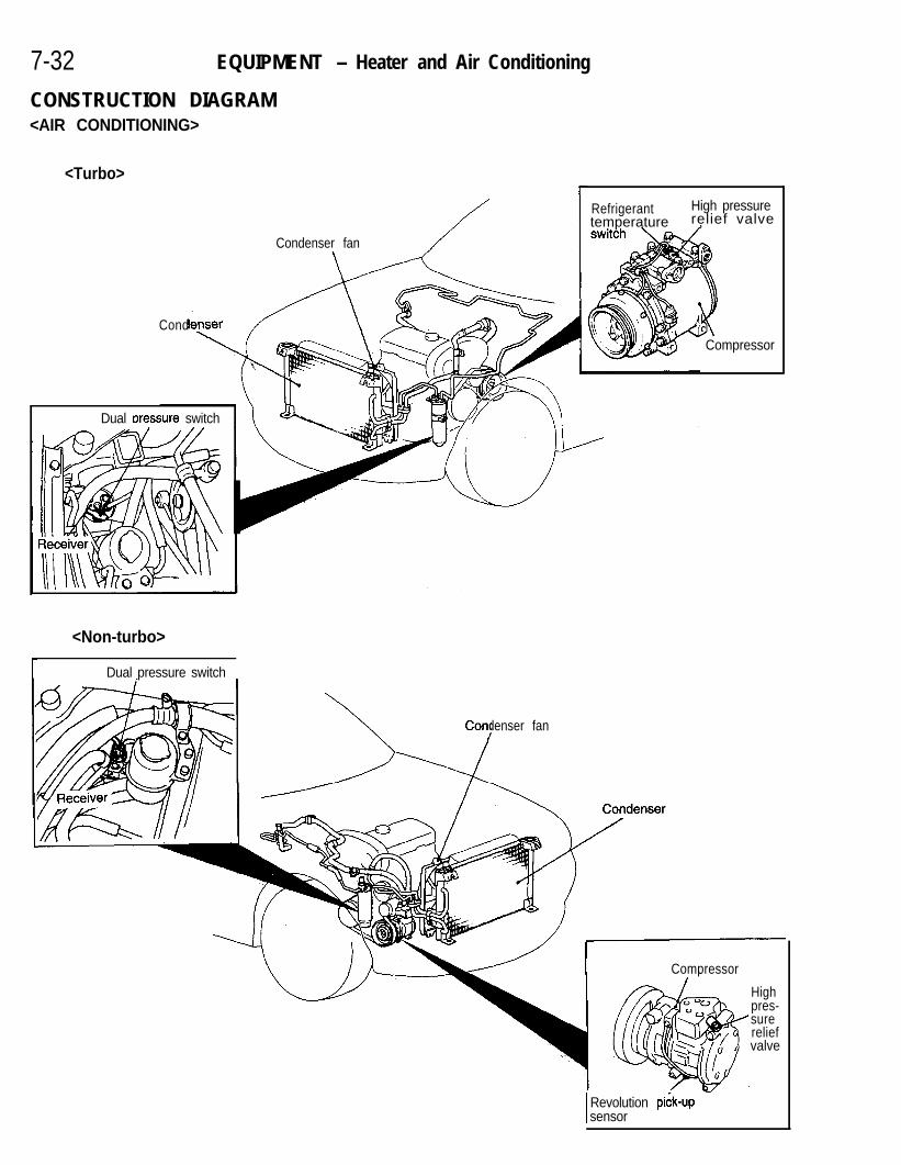
7-32 EQUIPMENT - Heater and Air Conditioning
CONSTRUCTION DIAGRAM<AIR CONDITIONING>
<Turbo>
Dual rxessure switch
Condenser fan i/
Refrigerant High pressuretemperature ,relief valve
Cond
<Non-turbo>
Dual pressure switch
Condenser fan‘::\I
Compressor
Compressor
Highpres-surereliefvalve
I Revolution pidk-upsensor AZOXO238

HeatFr unit Fin therm0 sensor
Evapo:ator Air inlet s&sor
<HEATER>
assembly
EQUIPMENT - Heater and Air Conditioning 7-33
To windshield (defroster)
ront door window
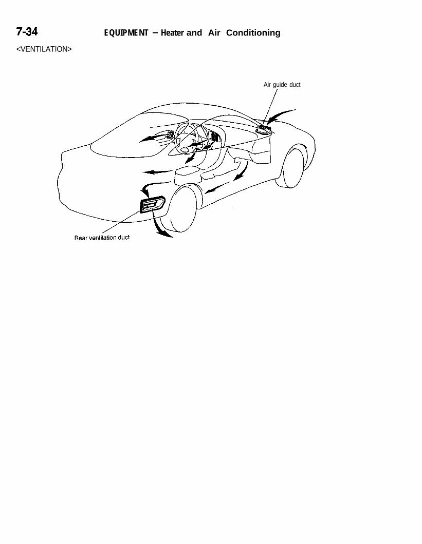
7-34 EQUIPMENT - Heater and Air Conditioning
<VENTILATION>
Air guide duct
/
A2OXO247

EQUIPMENT - Heater and Air Conditioning 7935A/C FUNCTIONAL COMPONENTS L ISTThe following table relates the A/C system’s functions to its components.
Heater/A/C control
Ducts
Refrigerant circuit
Fin therm0 sensor

7-36 EQUIPMENT - Heater and Air Conditioning
ON
b
OFF ---I
110(230)
165 Temperature(329) “C (“F)
1
REFRIGERANT TEMPERATURE SWITCH<TURBO>The refrigerant temperature switch detects the temperatureof the refrigerant at the delivery port of the A/C compressorto provide the ON/OFF control of the A/C compressor.For the location of the refrigerant temperature switch, referto the Construction Diagram on P.7-32.
AUTO COMPRESSOR-ECMThe auto compressor-ECM uses the signals sent from theA/C switch, fin therm0 sensor and air inlet sensor to providethe ON/OFF control of the magnetic clutch.
AUTO COMPRESSOR-ECM CONTROL CHARACTERISTICS DIAGRAM
15 (59)
G‘e9fi5 IO (50)$E8550
2Tig 5(41)
2ii
A/C mode ON
A/C mode OFF
ECONO mode ON
A/C and ECONO modes ON
\4°C (39°F)
Differential3°C (37’F)
A/C and ECONO modes OFF
I
Low 4Inlet air temperature
* High

EQUIPMENT - Heater and Air Conditioning 7-37
COMPRESSOR
Ll The A/C system on the non-turbo models incor-
porates a belt locking control function whichprevents the belts from being broken due toa slip that would occur when the compressoris locked. This function is achieved by the beltlock controller located below the blower motor.The controller compares the compressor speedobtained from the compressor revolution pick-upsensor with the engine speed and stops the
‘- ’ ’
Blinking A/C switch
cNon-turbo>
z;;pressor
<Turbo>
Compressorside
Valve characteristics1 0 0(6,102)
Fully open
A/C if the result of the calculation exceeds thepredetermined value.When the compressor is locked, the compressoroperation indicator light in the A/C switch blinksto warn the driver of the abnormal condition.
* A high pressure relief valve is provided to limitthe release of the refrigerant into air to a mini-mum when the high-pressure side pressure be-comes too high.
<Non-turbo> High pressurerelief valve
<Turbo> High pressurerelief valve
HIGH PRESSURE RELIEF VALVEThe valve, which is normally closed by the spring force, isforced open to release the refrigerant into open air when thehigh-pressure side pressure becomes so high that it overcomesthe spring force. When the pressure is lowered back to thenormal level, the valve is closed by the spring force not tolet out any more refrigerant.

7-38 EQUIPMENT - Heater and Air Conditioning
A/C COMPRESSOR CONTROLIf any of the switches and sensors is caused tobe OFF, the compressor clutch relay and compres-sor magnet clutch are forced to the OFF state.
Blower switch Manually set to ON and OFF
I-W switch Manually set to ON and OFF
: Dual pressure switch Low pressure switch OFF at 200 kPa (29 psi) or lower;‘2=e
ON at 220 kPa (32 psi) or higher
E0 High pressure switch OFF at 3,140 kPa (456 psi) or lower;b ON at 2,550 kPa (370 psi) or higheriiz Refrigerant temperature switch <Turbo> ON at approx. 110°C (230°F) or lower;
-EOFF at approx. 165°C (329°F) or higher
CrJ6 Air inlet sensor Measure the evaporator inlet air and surface temper-.=2
atures and input the measured data to the auto com-Fin therm0 sensor pressor-ECM. (Refer to the auto compressor-ECM
control characteristic diagram on P.7-36.)
Revolution pick-up sensor <Non-turbo> OFF when compressor slipping rate(s) is 70% ormore
<Turbo>Ignition switch (IG2) Fusible link
Autocompressor-ECM
Air therm0 Fin therm0sensor sensor
____-- -------.
Fuse
1 A/C, compressorFF clutch relay
Compressor

EQUIPMENT - Heater and Air Conditioning
<Non-turbo>
i
Ignition switch (IG2)
Auto compressor-ECM
Ignition coil
n
Air therm0sensor
Ided I
Fin thermo. .._.... -sensor
Dualpressureswitch
Revolutionpick-up sensor
Fusible link
Compressor

7-40 EQUIPMENT - Heater and Air Conditioning
Meltablebolt /(Abolished)
w
iccan
Section A-A ’
it
New refrigerantsystem
Conventionalrefrigerantsystem
Charging hose
C O N D E N S E R F A N A N D R A D I A T O R F A N C O N -T R O LFor information on condenser fan and radiator fan control,refer to Group 1 Control System of Engine.
RECEIVERl The new refrigerant (R134a) is highly hygroscopic and
would require much more amount of conventional desiccant(silica gel) to be kept dry.The new desiccant (molecular sieve) used for drying therefrigerant has enough capacity to absorb moisture withoutneed for change to the receiver capacity.
l In the conventional design, the meltable bolt on the receiverfuses to let out the refrigerant gas in its entirety into openair when the high-pressure side pressure becomes toohigh.The new system has a relief valve in the compressor whichplays the same role as the meltable bolt but closes afterrelease of only necessary quantity of refrigerant, so thatthe amount of released refrigerant is limited to the minimum.NOTE ‘2For details about the relief valve, see COMPRESSOR,P.7-37.
SERVICE VALVEA quick-disconnect type joint, instead of conventional screw-intype joint, is used for the service valve to prevent incorrectcharging and enhance serviceability.