electric actuator - — pneumac
TRANSCRIPT
LJ1H20
90
LEJS40
5888
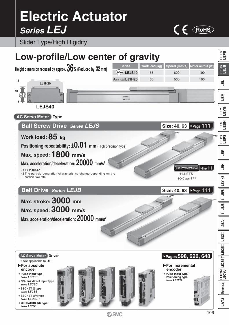
Electric Actuator
Slider Type/High Rigidity
Series LEJ RoHS
Series Work load [kg] Speed [mm/s] Motor output [W]
LEJS40 55 600 100
(Former model) LJ1H20 30 500 100
Ball Screw Drive Series LEJS
Belt Drive Series LEJB
Low-profi le/Low center of gravityHeight dimension reduced by approx. 36% (Reduced by 32 mm)
∗1 ISO14644-1∗2 The particle generation characteristics change depending on the
suction fl ow rate. ISO Class 4∗1∗2
¡ Pulse input typeSeries LECSB
¡ CC-Link direct input typeSeries LECSC
¡ SSCNET # typeSeries LECSS
¡ SSCNET #/H typeSeries LECSS-T
¡ MECHATROLINK typeSeries LECY�
�Page 11111-LEFS
Clean Room Specifi cation
Max. stroke: 3000 mm
Max. speed: 3000 mm/s
Max. acceleration/deceleration: 20000 mm/s2
Size: 40, 63
Size: 40, 63
TypeAC Servo Motor
�Page 111
�Page 111
Work load: 85 kg
Positioning repeatability: ±0.01 mm (High precision type)
Max. speed: 1800 mm/s
Max. acceleration/deceleration: 20000 mm/s2
�Pages 598, 620, 648
� For absoluteencoder
�For incremental encoder
¡ Pulse input type/Positioning typeSeries LECSA
∗ Not applicable to UL.
AC Servo Motor Driver
106
LE
FS
LE
FB
LE
LL
EJS
LE
JBL
EM
LE
YL
EY
GL
ES
LE
SH
LE
PY
LE
PS
LE
RL
EH
LEY-
X511
-LEF
S11
-LEJ
S25
A-
LEC
YMLE
CYU
LECS
S-T
LA
T3
Moto
rless
LEC
SL
EC
W
L
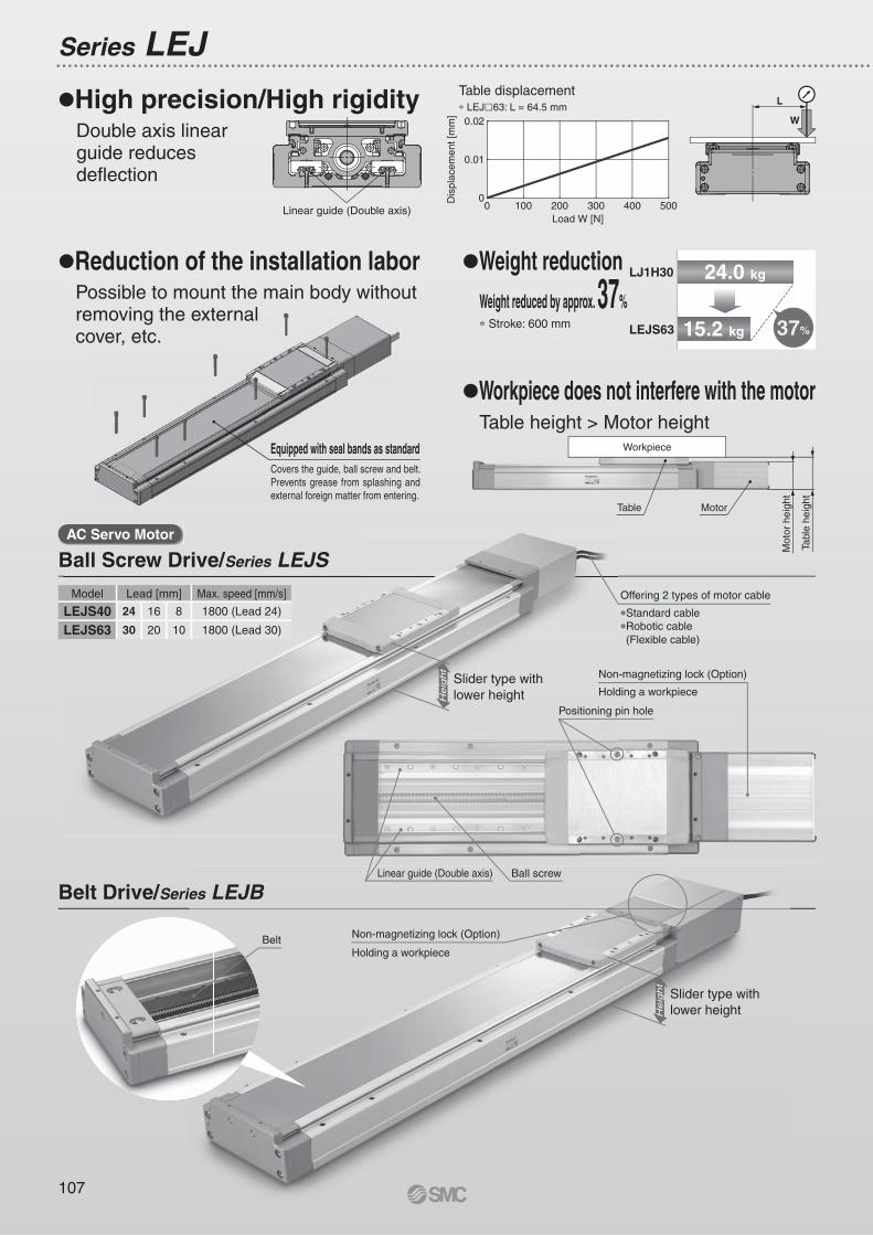
24.0 kg
15.2 kg 37%
He
igh
t
He
igh
t
0.02
0.01
00 100 200 300 400 500D
ispl
acem
ent [
mm
]
Load W [N]
Ball Screw Drive/Series LEJS
Belt Drive/Series LEJB
Series LEJ
Reduction of the installation laborPossible to mount the main body without removing the external cover, etc.
Workpiece does not interfere with the motorTable height > Motor height
Weight reductionWeight reduced by approx. 37% Stroke: 600 mm
High precision/High rigidityDouble axis linear guide reduces deflection
Equipped with seal bands as standardCovers the guide, ball screw and belt. Prevents grease from splashing and external foreign matter from entering.
AC Servo Motor
Tabl
e he
ight
Mot
or h
eigh
t
Motor
Workpiece
Linear guide (Double axis)
Table
Table displacement LEJ 63: L = 64.5 mm
Belt
Slider type withlower height
Slider type withlower height
Offering 2 types of motor cable
Standard cableRobotic cable (Flexible cable)
Holding a workpiece
Non-magnetizing lock (Option)
Positioning pin hole
Ball screwLinear guide (Double axis)
Holding a workpiece
Non-magnetizing lock (Option)
LEJS63
LJ1H30
Model Lead [mm] Max. speed [mm/s]
LEJS40 24 16 8 1800 (Lead 24)
LEJS63 30 20 10 1800 (Lead 30)
107
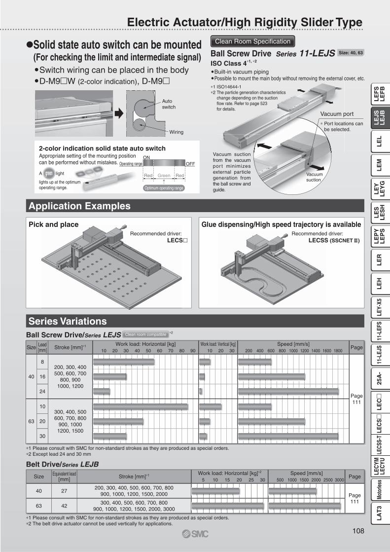
Operating range OFFON
Red Green Red
Optimum operating range
Size Lead[mm] Stroke [mm] 1 Work load: Horizontal [kg] Work load: Vertical [kg] Speed [mm/s]
Page10 20 30 40 50 60 70 80 90 10 20 30 200 400 600 800 1000 1200 1400 1600 1800
40
8200, 300, 400500, 600, 700
800, 9001000, 1200
Page 111
16
24
63
10300, 400, 500600, 700, 800
900, 10001200, 1500
20
30
Size Equivalent lead[mm] Stroke [mm] 1 Work load: Horizontal [kg] 2 Speed [mm/s]
Page5 10 15 20 25 30 500 1000 1500 2000 2500 3000
40 27 200, 300, 400, 500, 600, 700, 800
900, 1000, 1200, 1500, 2000 Page 111
63 42300, 400, 500, 600, 700, 800
900, 1000, 1200, 1500, 2000, 3000
Application Examples
Series VariationsBall Screw Drive/Series LEJS
Belt Drive/Series LEJB
1 Please consult with SMC for non-standard strokes as they are produced as special orders.2 Except lead 24 and 30 mm
1 Please consult with SMC for non-standard strokes as they are produced as special orders.2 The belt drive actuator cannot be used vertically for applications.
Electric Actuator/High Rigidity Slider Type
Solid state auto switch can be mounted (For checking the limit and intermediate signal)
Switch wiring can be placed in the bodyD-M9 W (2-color indication), D-M9
A light
lights up at the optimumoperating range.
2-color indication solid state auto switchAppropriate setting of the mounting positioncan be performed without mistakes.
green
Recommended driver: LECS
Recommended driver: LECSS (SSCNET )
Glue dispensing/High speed trajectory is availablePick and place
Clean room compatible 2
ISO Class 4 1, 2 Built-in vacuum pipingPossible to mount the main body without removing the external cover, etc.
Vacuum suction from the vacuum por t minimizes external particle generation from the ball screw and guide.
1 ISO14644-12 The particle generation characteristics
change depending on the suction flow rate. Refer to page 523 for details.
Vacuumsuction
Ball Screw Drive Series 11-LEJS
Port locations can be selected.
Vacuum port
Size: 40, 63
Clean Room Specification
Autoswitch
Wiring
108
LE
FS
LE
FB
LE
LL
EJS
LE
JBL
EM
LE
YL
EY
GL
ES
LE
SH
LE
PY
LE
PS
LE
RL
EH
LEY-
X511
-LEF
S11
-LEJ
S25
A-
LEC
YMLE
CYU
LECS
S-T
LA
T3
Moto
rless
LEC
SL
EC
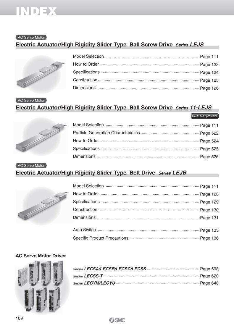
Model Selection Page 111
How to Order Page 123
Specifi cations Page 124
Construction Page 125
Dimensions Page 126
Model Selection Page 111
Particle Generation Characteristics Page 522
How to Order Page 524
Specifi cations Page 525
Dimensions Page 526
Series LECSA/LECSB/LECSC/LECSS Page 598
Series LECSS-T Page 620
Series LECYM/LECYU Page 648
Model Selection Page 111
How to Order Page 128
Specifi cations Page 129
Construction Page 130
Dimensions Page 131
Auto Switch Page 133
Specifi c Product Precautions Page 136
Electric Actuator/High Rigidity Slider Type Ball Screw Drive Series LEJS
INDEX
Electric Actuator/High Rigidity Slider Type Ball Screw Drive Series 11-LEJS
Electric Actuator/High Rigidity Slider Type Belt Drive Series LEJB
AC Servo Motor
AC Servo Motor
AC Servo Motor
Clean Room Specifi cation
AC Servo Motor Driver
109
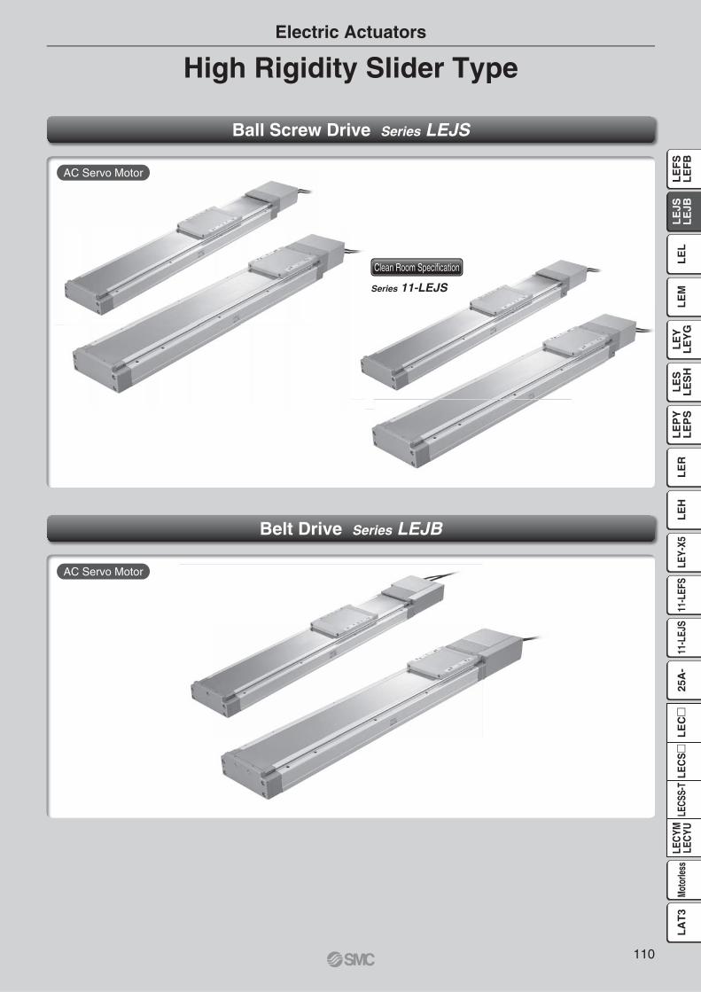
High Rigidity Slider TypeElectric Actuators
Ball Screw Drive Series LEJS
Belt Drive Series LEJB
Series 11-LEJS
AC Servo Motor
AC Servo Motor
Clean Room Specifi cation
110
LE
FS
LE
FB
LE
LL
EJS
LE
JBL
EM
LE
YL
EY
GL
ES
LE
SH
LE
PY
LE
PS
LE
RL
EH
LEY-
X511
-LEF
S11
-LEJ
S25
A-
LEC
YMLE
CYU
LECS
S-T
LA
T3
Moto
rless
LEC
SL
EC
T1
a1 a2
L
Spe
ed: V
[mm
/s]
Time[s]
T2
T6
T3 T4 T5
L3
Mep
m
100
WLead 20: LEJS63 A
Lead 10: LEJS63 B
Lead 30: LEJS63 H
Area where the regenerationoption is required.
0
10
20
30
40
50
60
70
80
90
0 200 400 600 800 1000 1200 1400 1600 1800
Wor
k lo
ad [k
g]
Speed [mm/s]
1000 mm/s2
3000 mm/s2
5000 mm/s2
10000 mm/s2
20000 mm/s2
0
500
1000
1500
2000
Work load [kg]
L3
[mm
]
0 10 40 5020 30 60 70 80
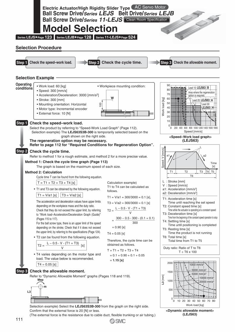
Selection Example
Step 1 Check the speed–work load. Step 2 Check the cycle time. Step 3 Check the allowable moment.
• Work load: 60 [kg]• Speed: 300 [mm/s]• Acceleration/Deceleration: 3000 [mm/s2]• Stroke: 300 [mm]• Mounting orientation: Horizontal• Motor type: Incremental encoder• External force: 10 [N]
• Workpiece mounting condition:Operating conditions
<Speed–Work load graph>(LEJS63)
<Dynamic allowable moment>(LEJS63)
Step 1 Check the speed–work load.Select the product by referring to “Speed-Work Load Graph” (Page 112).
Selection example) The LEJS63S3B-300 is temporarily selected based on thegraph shown on the right side.
The regeneration option may be necessary.Refer to page 112 for “Required Conditions for Regeneration Option”.
Step 2 Check the cycle time.
Method 2: Calculation
Refer to method 1 for a rough estimate, and method 2 for a more precise value.
Cycle time T can be found from the following equation.
Method 1: Check the cycle time graph (Page 113)The graph is based on the maximum speed of each size.
T = T1 + T2 + T3 + T4 [s]
T4 = 0.05 [s]
T1 = V/a1 [s] T3 = V/a2 [s]
T2 = [s]L − 0.5 · V · (T1 + T3)
V
• T4 varies depending on the motor type and load. The value below is recommended.
• T2 can be found from the following equation.
• T1 and T3 can be obtained by the following equation.
The acceleration and deceleration values have upper limits depending on the workpiece mass and the duty ratio.Check that they do not exceed the upper limit, by referring to “Work load–Acceleration/Deceleration Graph (Guide)” (Pages 115 to 117).For the ball screw type, there is an upper limit of the speed depending on the stroke. Check that if it does not exceed the upper limit, by referring to the specifi cations (Page 124).
Step 3 Check the allowable moment.
L : Stroke [mm]V : Speed [mm/s]a1: Acceleration [mm/s2]a2: Deceleration [mm/s2]
Duty ratio: Ratio of T to T6T ÷ T6 x 100
T1: Acceleration time [s]Time until reaching the set speed
T2: Constant speed time [s]Time while the actuator is operating at a constant speed
T3: Deceleration time [s]Time from the beginning of the constant speed operation to stop
T4: Settling time [s]Time until positioning is completed
T5: Resting time [s]Time the product is not running
T6: Total time [s]Total time from T1 to T5
Calculation example)T1 to T4 can be calculated as follows.
T1 = V/a1 = 300/3000 = 0.1 [s],
T3 = V/a2 = 300/3000 = 0.1 [s]
T4 = 0.05 [s]
Therefore, the cycle time can be obtained as follows.
T = T1 + T2 + T3 + T4
= 0.1 + 0.90 + 0.1 + 0.05
= 1.15 [s]
T2 =
=
= 0.90 [s]
L − 0.5 · V · (T1 + T3)
V
300 − 0.5 · 300 · (0.1 + 0.1)
300
Refer to “Dynamic Allowable Moment” graphs (Pages 118 and 119).
Selection example) Select the LEJS63S3B-300 from the graph on the right side.Confi rm that the external force is 20 [N] or less.(The external force is the resistance due to cable duct, fl exible trunking or air tubing.)
Selection Procedure
Series LEJSsPage 123 Series LEJBsPage 128 Series 11-LEJSsPage 524
Electric Actuator/High Rigidity Slider Type AC Servo Motor
Ball Screw Drive/Series LEJS Belt Drive/Series LEJBBall Screw Drive/Series 11-LEJS Clean Room Specification
Model Selection
otor
LEJBcation
B
111

Wor
k lo
ad [k
g]
Speed [mm/s]
0
10
20
30
40
50
60
0 200 400 600 800 1000 1200 1400 1600 1800
A
A
A
Area where the regeneration option is required.
Lead 24: LEJS40 H
Lead 8: LEJS40 B
Lead 16: LEJS40 A
010
20
30
40
50
60
70
80
90
0 200 400 600 800 1000 1200 1400 1600 1800
Wor
k lo
ad [k
g]
Speed [mm/s]
A
A
A
Lead 10: LEJS63 B
Lead 20: LEJS63 A
Area where the regenerationoption is required.
Lead 30: LEJS63 H
0 200 400 600 800 1000 1200 1400 1600 18000
5
10
7.5
2.5
Wor
k lo
ad [k
g]
Speed [mm/s]
A
Lead 24: LEJS40 H
Lead 16: LEJS40 A
Area where the regenerationoption is required.
Lead 8: LEJS40 B
0
5
10
15
20
0 200 400 600 800 1000 1200 1400 1600 1800
Wor
k lo
ad [k
g]
Speed [mm/s]
Lead 30: LEJS63 H
Lead 20: LEJS63 A
Area where the regeneration option is required.A
B
Lead 10: LEJS63 B
0 500 1000 1500 20000
5
10
15
20
Wor
k lo
ad [k
g]
Speed [mm/s]
A
Area where the regeneration option is required.
If the stroke exceeds 1000 mm.
0
5
10
15
20
25
30
0 500 1000 1500 2000 2500 3000
Wor
k lo
ad [k
g]
Speed [mm/s]
A
Area where the regeneration option is required.
Speed−Work Load Graph/Required Conditions for “Regeneration Option”(Guide)
LEJS40/Ball Screw Drive LEJS63/Ball Screw DriveHorizontal Horizontal
Vertical Vertical
LEJB40/Belt Drive LEJB63/Belt Drive
∗ When the stroke of the LEJB40 series exceeds 1000 mm, the work load is 10 kg.
Horizontal Horizontal
Required conditions for “Regeneration option” “Regeneration Option” Models∗ Regeneration option is required when using product above regeneration line in graph.
(Order separately.)Operatingcondition
Regenerative condition
Regeneration option
A Duty ratio100%
LEC-MR-RB-032
B LEC-MR-RB-12
Allowable Stroke Speed
ModelAC servo
motorLead Stroke [mm]
Symbol [mm] Up to 200 Up to 300 Up to 400 Up to 500 Up to 600 Up to 700 Up to 800 Up to 900 Up to 1000 Up to 1100 Up to 1200 Up to 1300 Up to 1400 Up to 1500
LEJS40 100 W/�40
H 24 1800 1580 1170 910 720 580 480 410 — — —
A 16 1200 1050 780 600 480 390 320 270 — — —
B 8 600 520 390 300 240 190 160 130 — — —
(Motor rotation speed) (4500 rpm) (3938 rpm) (2925 rpm) (2250 rpm) (1800 rpm) (1463 rpm) (1200 rpm) (1013 rpm) — — —
LEJS63 200 W/�60
H 30 — 1800 1390 1110 900 750 630 540 470 410
A 20 — 1200 930 740 600 500 420 360 310 270
B 10 — 600 460 370 300 250 210 180 150 130
(Motor rotation speed) — (3600 rpm) (2790 rpm) (2220 rpm) (1800 rpm) (1500 rpm) (1260 rpm) (1080 rpm) (930 rpm) (810 rpm)
[mm/s]
112
Model Selection Series LEJAC Servo Motor Clean Room Specification
LE
FS
LE
FB
LE
LL
EJS
LE
JBL
EM
LE
YL
EY
GL
ES
LE
SH
LE
PY
LE
PS
LE
RL
EH
LEY-
X511
-LEF
S11
-LEJ
S25
A-
LEC
YMLE
CYU
LECS
S-T
LA
T3
Moto
rless
LEC
SL
EC

Cyc
le ti
me
[s]
Stroke [mm]0 1200200 400 600 800 1000
0.0
0.5
1.0
1.5
2.0
Acceleration/Deceleration: 5000 mm/s2
Acceleration/Deceleration: 10000 mm/s2
Acceleration/Deceleration: 20000 mm/s2
Cyc
le ti
me
[s]
Stroke [mm]0 12001000200 400 600 800
0.0
0.5
1.0
1.5
2.0
2.5
3.0
Acceleration/Deceleration: 5000 mm/s2
Acceleration/Deceleration: 10000 mm/s2
Acceleration/Deceleration: 20000 mm/s2
Cyc
le ti
me
[s]
Stroke [mm]0 1200200 400 600 800 1000
0.0
0.5
1.0
1.5
2.0
2.5
3.0
3.5
4.0
4.5
5.0
5.5
6.0
Acceleration/Deceleration: 5000 mm/s2
Acceleration/Deceleration: 10000 mm/s2
Acceleration/Deceleration: 20000 mm/s2
Acceleration/Deceleration: 5000 mm/s2
Acceleration/Deceleration: 10000 mm/s2
Acceleration/Deceleration: 20000 mm/s2
Cyc
le ti
me
[s]
Stroke [mm]0 1000200 400 600 800
0.0
0.5
1.0
1.5
2.0
Cyc
le ti
me
[s]
Stroke [mm]0 1000200 400 600 800
0.0
0.5
1.0
1.5
2.0
2.5
3.0
Acceleration/Deceleration: 5000 mm/s2
Acceleration/Deceleration: 10000 mm/s2
Acceleration/Deceleration: 20000 mm/s2
Cyc
le ti
me
[s]
Stroke [mm]0 1000200 400 600 800
0.0
0.5
1.0
1.5
2.0
2.5
3.0
3.5
4.0
4.5
5.0
5.5
Acceleration/Deceleration: 5000 mm/s2
Acceleration/Deceleration: 10000 mm/s2
Acceleration/Deceleration: 20000 mm/s2
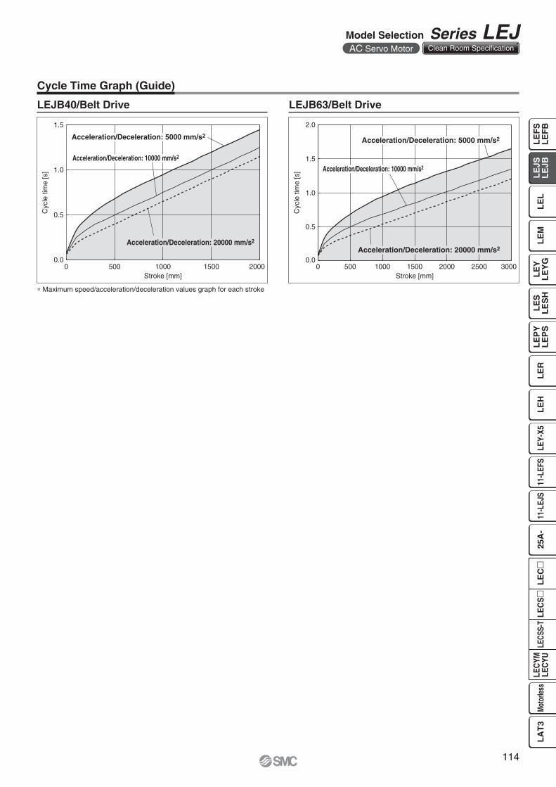
Cycle Time Graph (Guide)
LEJS40/Ball Screw Drive LEJS63/Ball Screw DriveLEJS40�H LEJS63�H
LEJS40�A
LEJS40�B
LEJS63�A
LEJS63�B
∗ Maximum speed/acceleration/deceleration values graph for each stroke
113
Series LEJAC Servo Motor Clean Room Specification
Cyc
le ti
me
[s]
Stroke [mm]0 2000500 1000 1500
0.0
0.5
1.0
1.5
Acceleration/Deceleration: 5000 mm/s2
Acceleration/Deceleration: 10000 mm/s2
Acceleration/Deceleration: 20000 mm/s2
Cyc
le ti
me
[s]
Stroke [mm]0 3000500 1000 1500 2000 2500
0.0
0.5
1.0
1.5
2.0
Acceleration/Deceleration: 5000 mm/s2
Acceleration/Deceleration: 10000 mm/s2
Acceleration/Deceleration: 20000 mm/s2
Cycle Time Graph (Guide)
LEJB40/Belt Drive LEJB63/Belt Drive
∗ Maximum speed/acceleration/deceleration values graph for each stroke
114
Model Selection Series LEJAC Servo Motor Clean Room Specification
LE
FS
LE
FB
LE
LL
EJS
LE
JBL
EM
LE
YL
EY
GL
ES
LE
SH
LE
PY
LE
PS
LE
RL
EH
LEY-
X511
-LEF
S11
-LEJ
S25
A-
LEC
YMLE
CYU
LECS
S-T
LA
T3
Moto
rless
LEC
SL
EC

0
5000
10000
15000
20000
0 5 10 15
Work load [kg]
Acc
eler
atio
n/D
ecel
erat
ion
[mm
/s2 ]
The value of 50% or less is the same as duty ratio 50%
Duty ratio: 100%
Duty ratio: 75%
Duty ratio: 50%
0
5000
10000
15000
20000
0 5 10 20 3015 25
Work load [kg]A
ccel
erat
ion/
Dec
eler
atio
n [m
m/s
2 ]
Duty ratio: 100%
Duty ratio: 75%
Duty ratio: 50%
Duty ratio: 25%
0
5000
10000
15000
20000
0 10 20 30
Work load [kg]
Acc
eler
atio
n/D
ecel
erat
ion
[mm
/s2 ]
The value of 50% or less is the same as duty ratio 50%
Duty ratio: 100%
Duty ratio: 75%
Duty ratio: 50%
0
5000
10000
15000
20000
0 10 20 30 40
Work load [kg]
Acc
eler
atio
n/D
ecel
erat
ion
[mm
/s2 ]
Duty ratio: 100%
Duty ratio: 50%
Duty ratio: 25%
Duty ratio: 75%
0
5000
10000
15000
20000
0 10 20 30 40 50
Work load [kg]
Acc
eler
atio
n/D
ecel
erat
ion
[mm
/s2 ] The value of 50% or less is the same as duty ratio 50%
Duty ratio: 100%
Duty ratio: 50%
Duty ratio: 75%
0
5000
10000
15000
20000
0 10 20 30 40 50 60 70 80
Work load [kg]
Acc
eler
atio
n/D
ecel
erat
ion
[mm
/s2 ]
Duty ratio: 100%
Duty ratio: 50%
Duty ratio: 25%
Duty ratio: 75%
Work Load–Acceleration/Deceleration Graph (Guide)
LEJS40/Ball Screw Drive: Horizontal
LEJS40�H LEJS63�H
LEJS40�A LEJS63�A
LEJS40�B LEJS63�B
LEJS63/Ball Screw Drive: Horizontal
115
Series LEJAC Servo Motor Clean Room Specification
0
5000
10000
15000
20000
0 1 2 3
Work load [kg]
Acc
eler
atio
n/D
ecel
erat
ion
[mm
/s2 ]
Duty ratio: 100%
Duty ratio: 50%
Duty ratio: 75%
The value of 50% or less is the same as duty ratio 50%
0
5000
10000
15000
20000
0 1 2 3 4 5 6
Work load [kg]A
ccel
erat
ion/
Dec
eler
atio
n [m
m/s
2 ]
Duty ratio: 100%
Duty ratio: 50%
Duty ratio: 25%
Duty ratio: 75%
0 1 2 3 4 50
5000
10000
15000
20000
Work load [kg]
Acc
eler
atio
n/D
ecel
erat
ion
[mm
/s2 ]
The value of 50% or less is the same as duty ratio 50%
Duty ratio: 100%
Duty ratio: 50%
Duty ratio: 75%
0
5000
10000
15000
20000
0 2.5 5 7.5 10
Work load [kg]
Acc
eler
atio
n/D
ecel
erat
ion
[mm
/s2 ]
Duty ratio: 100%
Duty ratio: 25%
Duty ratio: 75%
Duty ratio: 50%
0
5000
10000
15000
20000
0 2.5 5 7.5 10
Work load [kg]
Acc
eler
atio
n/D
ecel
erat
ion
[mm
/s2 ]
The value of 50% or less is the same as duty ratio 50%
Duty ratio: 100%
Duty ratio: 50%
Duty ratio: 75%
0
5000
10000
15000
20000
0 5 10 15 20
Work load [kg]
Acc
eler
atio
n/D
ecel
erat
ion
[mm
/s2 ]
Duty ratio: 50%
Duty ratio: 25%
Duty ratio: 75%
Duty ratio: 100%
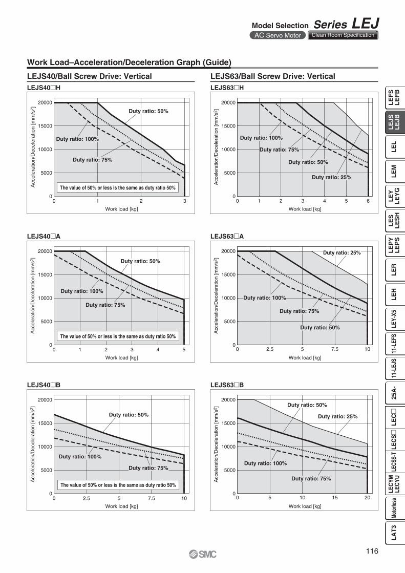
LEJS40�H LEJS63�H
LEJS40�A LEJS63�A
Work Load–Acceleration/Deceleration Graph (Guide)
LEJS40/Ball Screw Drive: Vertical LEJS63/Ball Screw Drive: Vertical
LEJS40�B LEJS63�B
116
Model Selection Series LEJAC Servo Motor Clean Room Specification
LE
FS
LE
FB
LE
LL
EJS
LE
JBL
EM
LE
YL
EY
GL
ES
LE
SH
LE
PY
LE
PS
LE
RL
EH
LEY-
X511
-LEF
S11
-LEJ
S25
A-
LEC
YMLE
CYU
LECS
S-T
LA
T3
Moto
rless
LEC
SL
EC
0
5000
10000
15000
20000
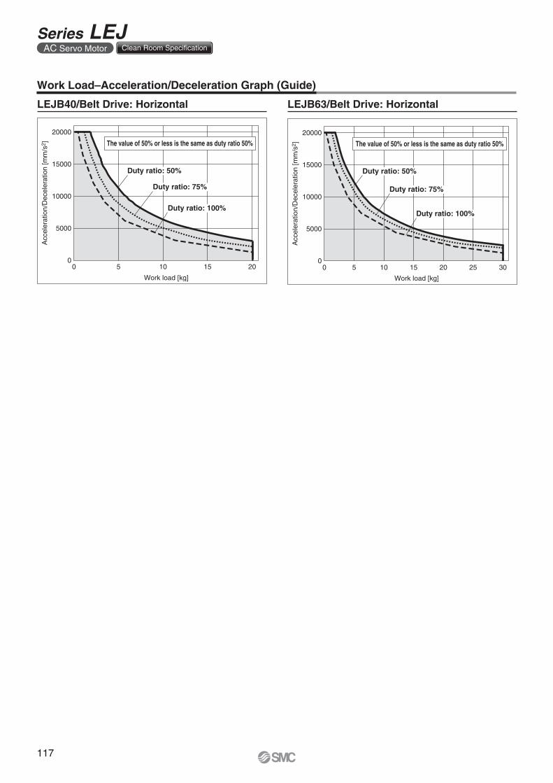
0 5 10 15 20
Work load [kg]
Acc
eler
atio
n/D
ecel
erat
ion
[mm
/s2 ] The value of 50% or less is the same as duty ratio 50%
Duty ratio: 100%
Duty ratio: 50%
Duty ratio: 75%
0
5000
10000
15000
20000
0 5 10 15 20 25 30
Work load [kg]
Acc
eler
atio
n/D
ecel
erat
ion
[mm
/s2 ] The value of 50% or less is the same as duty ratio 50%
Duty ratio: 100%
Duty ratio: 50%
Duty ratio: 75%
Work Load–Acceleration/Deceleration Graph (Guide)
LEJB40/Belt Drive: Horizontal LEJB63/Belt Drive: Horizontal
117
Series LEJAC Servo Motor Clean Room Specification
mMe
L1
L2
mMe
mMe
L3
0
200
400
600
800
1000
0
200
400
600
800
1000
0
500
1000
1500
2000
Work load [kg]
L1
[mm
]
Work load [kg]
L1
[mm
]
0
500
1000
1500
2000
Work load [kg]L
1 [m
m]
Work load [kg]
L1
[mm
]
0 105 15 200 105 15 20 30250 10 40 5020 300 10 40 5020 30 60 70 80
0
200
400
600
800
1000
0
200
400
600
800
1000
0
500
1000
1500
2000
Work load [kg]
L2
[mm
]
Work load [kg]L
2 [m
m]
0
500
1000
1500
2000
Work load [kg]
L2
[mm
]
Work load [kg]
L2
[mm
]
0 105 15 200 105 15 20 30250 10 40 5020 300 10 40 5020 30 60 70 80
0
200
400
600
800
1000
0
200
400
600
800
1000
0
500
1000
1500
2000
Work load [kg]
L3
[mm
]
Work load [kg]
L3
[mm
]
0
500
1000
1500
2000
Work load [kg]
L3
[mm
]
Work load [kg]
L3
[mm
]
0 105 15 200 105 15 20 30250 10 40 5020 300 10 40 5020 30 60 70 80
0
200
400
600
800
1000
0
200
400
600
800
1000
0
500
1000
1500
2000
Work load [kg]
L4
[mm
]
Work load [kg]
L4
[mm
]
0
500
1000
1500
2000
Work load [kg]
L4
[mm
]
Work load [kg]
L4
[mm
]
0 105 15 200 105 15 20 30250 10 40 5020 300 10 40 5020 30 60 70 80
0
200
400
600
800
1000
0
200
400
600
800
1000
0
500
1000
1500
2000
Work load [kg]
L5
[mm
]
Work load [kg]
L5
[mm
]
0
500
1000
1500
2000
Work load [kg]
L5
[mm
]
Work load [kg]
L5
[mm
]
0 105 15 200 105 15 20 30250 10 40 5020 300 10 40 5020 30 60 70 80
0
200
400
600
800
1000
0
200
400
600
800
1000
0
500
1000
1500
2000
Work load [kg]
L6
[mm
]
Work load [kg]
L6
[mm
]
0
500
1000
1500
2000
Work load [kg]
L6
[mm
]
Work load [kg]
L6
[mm
]
0 105 15 200 105 15 20 30250 10 40 5020 300 10 40 5020 30 60 70 80
5000 mm/s2 or less is same as 5000 mm/s2
5000 mm/s2 or less is same as 5000 mm/s2
5000 mm/s2 or less is same as 5000 mm/s2
5000 mm/s2 or less is same as 5000 mm/s2
5000 mm/s2 or less is same as 5000 mm/s2
5000 mm/s2 or less is same as 5000 mm/s2
5000 mm/s2 or less is same as 5000 mm/s2
5000 mm/s2 or less is same as 5000 mm/s2
mMe
L4
L5
mMe
mMe
L6
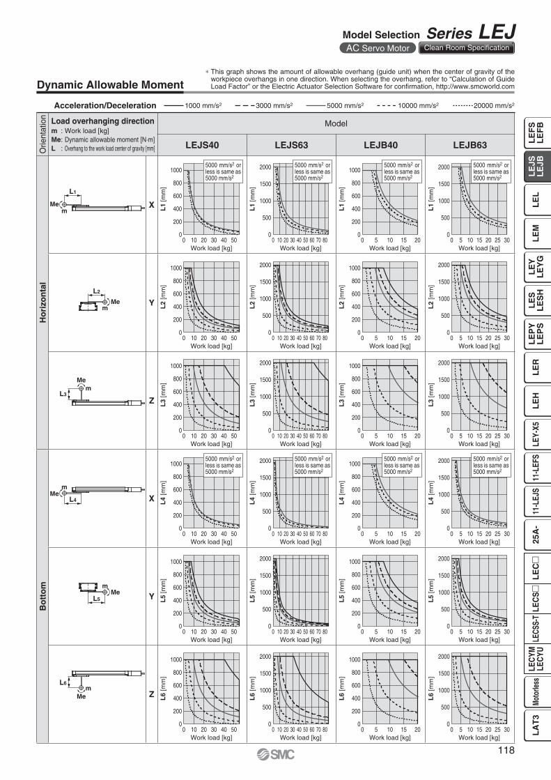
Dynamic Allowable Moment
Orie
ntat
ion Load overhanging direction
m : Work load [kg]Me: Dynamic allowable moment [N·m]L : Overhang to the work load center of gravity [mm]
Model
LEJS40 LEJS63 LEJB40 LEJB63
Ho
rizo
nta
l
X
Y
Z
Bo
tto
m
X
Y
Z
Acceleration/Deceleration 1000 mm/s2 5000 mm/s2 10000 mm/s23000 mm/s2 20000 mm/s2
∗ This graph shows the amount of allowable overhang (guide unit) when the center of gravity of the workpiece overhangs in one direction. When selecting the overhang, refer to “Calculation of Guide Load Factor” or the Electric Actuator Selection Software for confi rmation, http://www.smcworld.com
118
Model Selection Series LEJAC Servo Motor Clean Room Specification
LE
FS
LE
FB
LE
LL
EJS
LE
JBL
EM
LE
YL
EY
GL
ES
LE
SH
LE
PY
LE
PS
LE
RL
EH
LEY-
X511
-LEF
S11
-LEJ
S25
A-
LEC
YMLE
CYU
LECS
S-T
LA
T3
Moto
rless
LEC
SL
EC
119
Series LEJAC Servo Motor Clean Room Specification
mMe
L10
mMe
L11
0
200
400
600
800
1000
0
200
400
600
800
1000
0
500
1000
1500
2000
Work load [kg]
L7
[mm
]
Work load [kg]
L7
[mm
]
0
500
1000
1500
2000
Work load [kg]L
7 [m
m]
Work load [kg]
L7
[mm
]
0 105 15 200 105 15 20 30250 10 40 5020 300 10 40 5020 30 60 70 80
0
200
400
600
800
1000
0
200
400
600
800
1000
0
500
1000
1500
2000
Work load [kg]
L8
[mm
]
Work load [kg]L
8 [m
m]
0
500
1000
1500
2000
Work load [kg]
L8
[mm
]
Work load [kg]
L8
[mm
]
0 105 15 200 105 15 20 30250 10 40 5020 300 10 40 5020 30 60 70 80
0
200
400
600
800
1000
0
200
400
600
800
1000
0
500
1000
1500
2000
Work load [kg]
L9
[mm
]
Work load [kg]
L9
[mm
]
0
500
1000
1500
2000
Work load [kg]
L9
[mm
]
Work load [kg]
L9
[mm
]
0 105 15 200 105 15 20 30250 10 40 5020 300 10 40 5020 30 60 70 80
0
200
400
600
800
1000
0
500
1000
1500
2000
Work load [kg]
L10
[mm
]
Work load [kg]
L10
[mm
]
0 10 155 20
0 10 155 20
0 2 8 104 6
0 2 8 104 60
200
400
600
800
1000
0
500
1000
1500
2000
Work load [kg]
L11
[mm
]
Work load [kg]
L11
[mm
]5000 mm/s2 or less is same as 5000 mm/s2
5000 mm/s2 or less is same as 5000 mm/s2
5000 mm/s2 or less is same as 5000 mm/s2
5000 mm/s2 or less is same as 5000 mm/s2
L7
mMe
mMe
L8
L9
mMe
Orie
ntat
ion Load overhanging direction
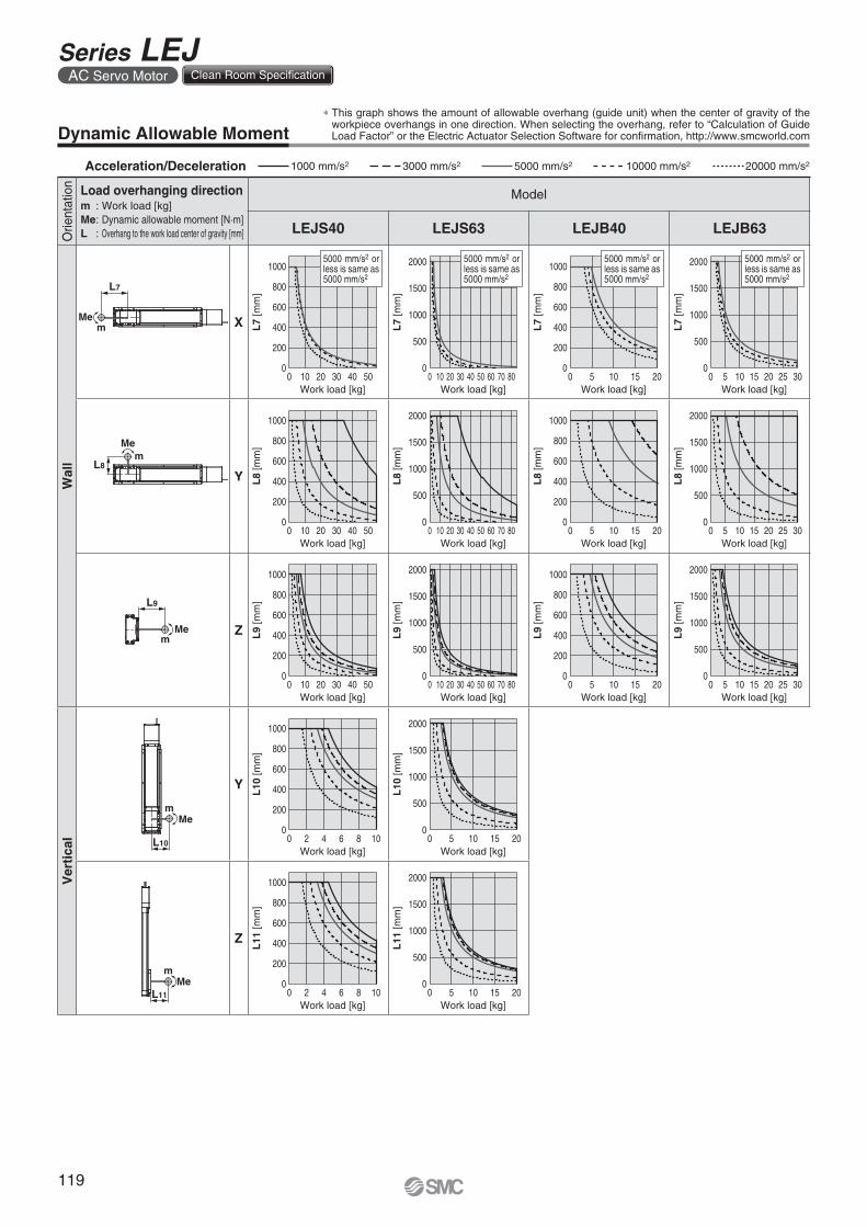
m : Work load [kg]Me: Dynamic allowable moment [N·m]L : Overhang to the work load center of gravity [mm]
Model
LEJS40 LEJS63 LEJB40 LEJB63
Wal
l
X
Y
Z
Ver
tica
l
Y
Z
Dynamic Allowable Moment∗ This graph shows the amount of allowable overhang (guide unit) when the center of gravity of the
workpiece overhangs in one direction. When selecting the overhang, refer to “Calculation of Guide Load Factor” or the Electric Actuator Selection Software for confi rmation, http://www.smcworld.com
Acceleration/Deceleration 1000 mm/s2 5000 mm/s2 10000 mm/s23000 mm/s2 20000 mm/s2
0
200
400
600
800
1000
L1
[mm
]
0 10 20 30 40 50
Work load [kg]
Lx
0
200
400
600
800
1000
0 10 20 30 40 50
L2
[mm
]
Work load [kg]
Ly
0
200
400
600
800
1000
0 10 20 30 40 50
L3
[mm
]
Work load [kg]
Lz
xy
z
xy
z
x z
y
x
z y
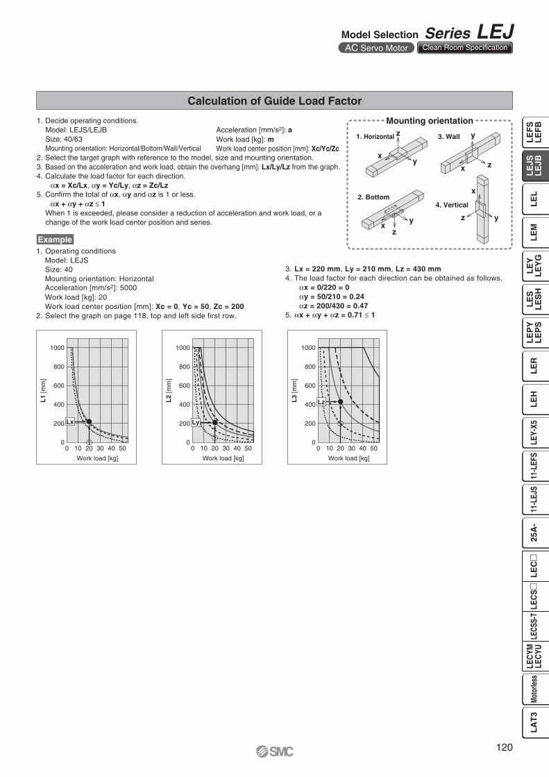
Calculation of Guide Load Factor
1. Operating conditionsModel: LEJSSize: 40Mounting orientation: HorizontalAcceleration [mm/s2]: 5000Work load [kg]: 20Work load center position [mm]: Xc = 0, Yc = 50, Zc = 200
2. Select the graph on page 118, top and left side fi rst row.
Example
Acceleration [mm/s2]: aWork load [kg]: mWork load center position [mm]: Xc/Yc/Zc
Mounting orientation
1. Horizontal 3. Wall
2. Bottom4. Vertical
1. Decide operating conditions.Model: LEJS/LEJBSize: 40/63Mounting orientation: Horizontal/Bottom/Wall/Vertical
2. Select the target graph with reference to the model, size and mounting orientation.3. Based on the acceleration and work load, obtain the overhang [mm]: Lx/Ly/Lz from the graph.4. Calculate the load factor for each direction.
αx = Xc/Lx, αy = Yc/Ly, αz = Zc/Lz5. Confi rm the total of αx, αy and αz is 1 or less.
αx + αy + αz ≤ 1When 1 is exceeded, please consider a reduction of acceleration and work load, or a change of the work load center position and series.
3. Lx = 220 mm, Ly = 210 mm, Lz = 430 mm4. The load factor for each direction can be obtained as follows.
αx = 0/220 = 0αy = 50/210 = 0.24αz = 200/430 = 0.47
5. αx + αy + αz = 0.71 ≤ 1
120
Model Selection Series LEJAC Servo Motor Clean Room Specification
LE
FS
LE
FB
LE
LL
EJS
LE
JBL
EM
LE
YL
EY
GL
ES
LE
SH
LE
PY
LE
PS
LE
RL
EH
LEY-
X511
-LEF
S11
-LEJ
S25
A-
LEC
YMLE
CYU
LECS
S-T
LA
T3
Moto
rless
LEC
SL
EC
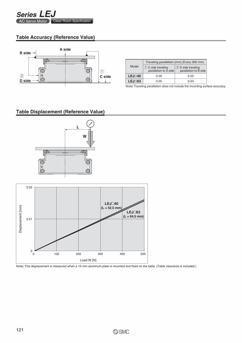
A side
C side
B side
D side
W
L
0.02
0.01
00 100 200 300 400 500
Dis
plac
emen
t [m
m]
Load W [N]
LEJ 40(L = 52.5 mm)
LEJ 63(L = 64.5 mm)
Table Accuracy (Reference Value)
Table Displacement (Reference Value)
Note) Traveling parallelism does not include the mounting surface accuracy.
Note) This displacement is measured when a 15 mm aluminum plate is mounted and fi xed on the table. (Table clearance is included.)
ModelTraveling parallelism [mm] (Every 300 mm)
q C side traveling parallelism to A side
w D side traveling parallelism to B side
LEJ�40 0.05 0.03
LEJ�63 0.05 0.03
121
Series LEJAC Servo Motor Clean Room Specification
122
LE
FS
LE
FB
LE
LL
EJS
LE
JBL
EM
LE
YL
EY
GL
ES
LE
SH
LE
PY
LE
PS
LE
RL
EH
LEY-
X511
-LEF
S11
-LEJ
S25
A-
LEC
YMLE
CYU
LECS
S-T
LA
T3
Moto
rless
LEC
SL
EC
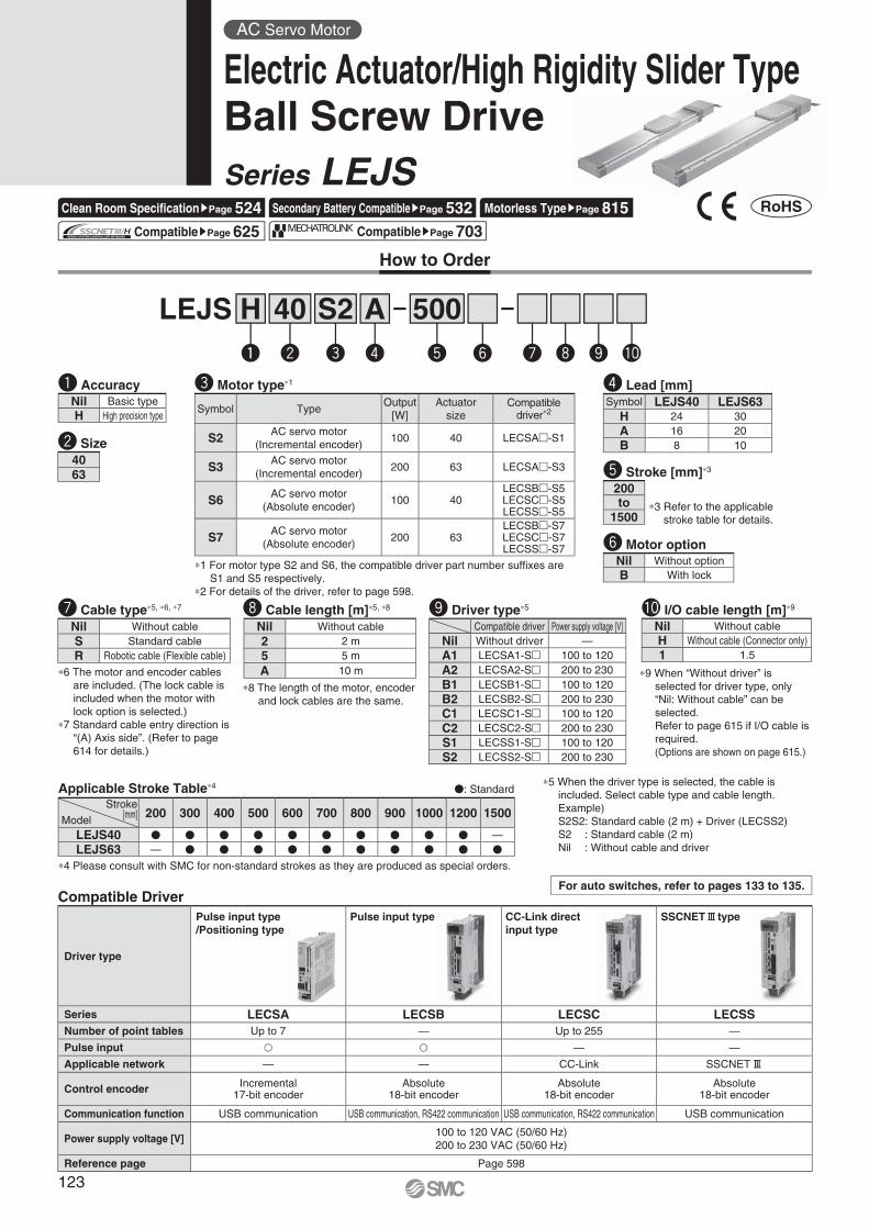
How to Order
Compatible DriverFor auto switches, refer to pages 133 to 135.
LEJS 40 500A
Applicable Stroke Table∗4 �: Standard
w e r t y u i o !0
∗4 Please consult with SMC for non-standard strokes as they are produced as special orders.
∗1 For motor type S2 and S6, the compatible driver part number suffi xes are S1 and S5 respectively.
∗2 For details of the driver, refer to page 598.
∗3 Refer to the applicable stroke table for details.
w Size
r Lead [mm]
y Motor option
t Stroke [mm]∗3
∗6 The motor and encoder cables are included. (The lock cable is included when the motor with lock option is selected.)
∗7 Standard cable entry direction is “(A) Axis side”. (Refer to page 614 for details.)
u Cable type∗5, ∗6, ∗7 i Cable length [m]∗5, ∗8
S2
e Motor type∗1
o Driver type∗5
∗5 When the driver type is selected, the cable is included. Select cable type and cable length.Example)S2S2: Standard cable (2 m) + Driver (LECSS2)S2 : Standard cable (2 m)Nil : Without cable and driver
∗8 The length of the motor, encoder and lock cables are the same.
Compatible driver Power supply voltage [V]Nil Without driver —A1 LECSA1-S� 100 to 120A2 LECSA2-S� 200 to 230B1 LECSB1-S� 100 to 120B2 LECSB2-S� 200 to 230C1 LECSC1-S� 100 to 120C2 LECSC2-S� 200 to 230S1 LECSS1-S� 100 to 120S2 LECSS2-S� 200 to 230
Symbol TypeOutput
[W]Actuator
sizeCompatible
driver∗2
S2 AC servo motor(Incremental encoder)
100 40 LECSA�-S1
S3 AC servo motor(Incremental encoder)
200 63 LECSA�-S3
S6 AC servo motor(Absolute encoder)
100 40LECSB�-S5LECSC�-S5LECSS�-S5
S7 AC servo motor(Absolute encoder)
200 63LECSB�-S7LECSC�-S7LECSS�-S7
Nil Without cableS Standard cableR Robotic cable (Flexible cable)
Nil Without cable2 2 m5 5 mA 10 m
Stroke[mm]Model
200 300 400 500 600 700 800 900 1000 1200 1500
LEJS40 � � � � � � � � � � —LEJS63 — � � � � � � � � � �
Symbol LEJS40 LEJS63H 24 30A 16 20B 8 10
4063
Driver type
Pulse input type/Positioning type
Pulse input type CC-Link direct input type
SSCNET# type
Series LECSA LECSB LECSC LECSSNumber of point tables Up to 7 — Up to 255 —
Pulse input � � — —
Applicable network — — CC-Link SSCNET#
Control encoder Incremental17-bit encoder
Absolute18-bit encoder
Absolute18-bit encoder
Absolute18-bit encoder
Communication function USB communication USB communication, RS422 communication USB communication, RS422 communication USB communication
Power supply voltage [V]100 to 120 VAC (50/60 Hz)200 to 230 VAC (50/60 Hz)
Reference page Page 598
Hq
!0 I/O cable length [m]∗9
Nil Without cableH Without cable (Connector only)1 1.5
∗9 When “Without driver” is selected for driver type, only “Nil: Without cable” can be selected.Refer to page 615 if I/O cable is required.(Options are shown on page 615.)
q AccuracyNil Basic typeH High precision type
200to
1500
Nil Without optionB With lock
AC Servo Motor
Electric Actuator/High Rigidity Slider TypeBall Screw DriveSeries LEJS
Clean Room Specifi cationsPage 524 Secondary Battery CompatiblesPage 532 Motorless TypesPage 815 CompatiblesPage 625 CompatiblesPage 703
123

Specifi cations
Note 1) Please consult with SMC for non-standard strokes as they are pro-duced as special orders.
Note 2) For details, refer to “Speed–Work Load Graph (Guide)” on page 112.Note 3) The allowable speed changes according to the stroke.Note 4) A reference value for correcting an error in reciprocal operation.Note 5) Impact resistance: No malfunction occurred when the actuator was
tested with a drop tester in both an axial direction and a perpendicular direction to the lead screw. (Test was performed with the actuator in the ini-tial state.)
Vibration resistance: No malfunction occurred in a test ranging be-tween 45 to 2000 Hz. Test was performed in both an axial direction and a perpendicular di-rection to the lead screw. (Test was performed with the actuator in the initial state.)
AC Servo Motor (100/200 W)Model LEJS40S 2
6 LEJS63S 37
Act
uat
or
spec
ifi ca
tio
ns
Stroke [mm] Note 1) 200, 300, 400, 500, 600, 700, 800900, 1000, 1200
300, 400, 500, 600, 700, 800, 9001000, 1200, 1500
Work load [kg] Note 2) Horizontal 15 30 55 30 45 85Vertical 3 5 10 6 10 20
Speed Note 3)
[mm/s]Strokerange
Up to 500 1800 1200 600 1800 1200 600501 to 600 1580 1050 520 1800 1200 600601 to 700 1170 780 390 1800 1200 600701 to 800 910 600 300 1390 930 460801 to 900 720 480 240 1110 740 370901 to 1000 580 390 190 900 600 3001001 to 1100 480 320 160 750 500 2501101 to 1200 410 270 130 630 420 2101201 to 1300 — — — 540 360 1801301 to 1400 — — — 470 310 1501401 to 1500 — — — 410 270 130
Max. acceleration/deceleration [mm/s2] 20000 (Refer to pages 115 and 116 for limit according to work load and duty ratio.)Positioning repeatability[mm]
Basic type ±0.02High precision type ±0.01
Lost motion[mm] Note 4)
Basic type 0.1 or lessHigh precision type 0.05 or less
Lead [mm] 24 16 8 30 20 10Impact/Vibration resistance [m/s2] Note 5) 50/20Actuation type Ball screwGuide type Linear guideOperating temperature range [°C] 5 to 40Operating humidity range [%RH] 90 or less (No condensation)Regeneration option May be required depending on speed and work load. (Refer to page 112.)
Ele
ctri
c sp
ecifi
cati
on
s Motor output [W]/Size [mm] 100/�40 200/�60Motor type AC servo motor (100/200 VAC)
EncoderMotor type S2, S3: Incremental 17-bit encoder (Resolution: 131072 p/rev)
Motor type S6, S7: Absolute 18-bit encoder (Resolution: 262144 p/rev)
Power consumption [W] Note 6) Horizontal 65 80Vertical 165 235
Standby power consumptionwhen operating [W] Note 7)
Horizontal 2 2Vertical 10 12
Max. instantaneous power consumption [W] Note 8) 445 725
Lock
uni
tsp
ecifi
catio
ns Type Note 9) Non-magnetizing lockHolding force [N] 67 101 203 220 330 660Power consumption at 20°C [W] Note 10) 6.3 7.9Rated voltage [V] 24 VDC 0
–10%
Weight
Model LEJS63Stroke [mm] 300 400 500 600 700 800 900 1000 1200 1500Product weight [kg] 11.4 12.7 13.9 15.2 16.4 17.7 18.9 20.1 22.6 26.4Additional weight with lock [kg] 0.4 (Incremental encoder)/0.7 (Absolute encoder)
Model LEJS40Stroke [mm] 200 300 400 500 600 700 800 900 1000 1200Product weight [kg] 5.6 6.4 7.1 7.9 8.7 9.4 10.2 11.0 11.7 13.3Additional weight with lock [kg] 0.2 (Incremental encoder)/0.3 (Absolute encoder)
Note 6) The power consumption (including the driver) is for when the actua-tor is operating.
Note 7) The standby power consumption when operating (including the driver) is for when the actuator is stopped in the set position during the operation.
Note 8) The maximum instantaneous power consumption (including the driver) is for when the actuator is operating.
Note 9) Only when motor option “With lock” is selected.Note 10) For an actuator with lock, add the power consumption for the lock.Note 11) Sensor magnet position is located in the table center. For detailed
dimensions, refer to “Auto Switch Mounting Position” on page 133.Note 12) Do not allow collisions at either end of the table traveling distance.
Additionally, when running the positioning operation, do not set within 2 mm of both ends.
Note 13) For the manufacture of intermediate strokes, please contact SMC.(LEJS40/Manufacturable stroke range: 200 to 1200 mm, LEJS63/Manufacturable stroke range: 300 to 1500 mm)
124
Electric Actuator/High Rigidity Slider TypeBall Screw Drive Series LEJS
AC Servo Motor
LE
FS
LE
FB
LE
LL
EJS
LE
JBL
EM
LE
YL
EY
GL
ES
LE
SH
LE
PY
LE
PS
LE
RL
EH
LEY-
X511
-LEF
S11
-LEJ
S25
A-
LEC
YMLE
CYU
LECS
S-T
LA
T3
Moto
rless
LEC
SL
EC
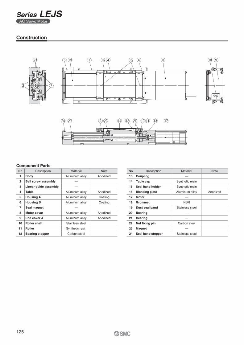
Component Parts
Construction
No Description Material Note
13 Coupling —
14 Table cap Synthetic resin
15 Seal band holder Synthetic resin
16 Blanking plate Aluminum alloy Anodized
17 Motor —
18 Grommet NBR
19 Dust seal band Stainless steel
20 Bearing —
21 Bearing —
22 Nut fi xing pin Carbon steel
23 Magnet —
24 Seal band stopper Stainless steel
No Description Material Note
1 Body Aluminum alloy Anodized
2 Ball screw assembly —
3 Linear guide assembly —
4 Table Aluminum alloy Anodized
5 Housing A Aluminum alloy Coating
6 Housing B Aluminum alloy Coating
7 Seal magnet —
8 Motor cover Aluminum alloy Anodized
9 End cover A Aluminum alloy Anodized
10 Roller shaft Stainless steel
11 Roller Synthetic resin
12 Bearing stopper Carbon steel
125
Series LEJSAC Servo Motor
Motor option B: With lock
+0.030 0ø6H9 ( ) depth 4+0.
030
06H
9 (
) d
epth
4
64
6 +0.030 05H9 ( ) depth 6
+0.030 0ø5H9 ( ) depth 6
58
50.5
36.5
130
100
56
M4 x 0.7 depth 8(F.G. terminal)
18
Body mountingreference plane
(128
)(160)
110
84
4 x M6 x 1 depth 10
94
(3.1)
100
105
35
25.5
Encoder cable(ø7)
Motor cable(ø6)
45
37
(4)
Stroke
A (Table traveling distance) Note 1)
L167 (B: With lock/207)
2 1
(60)(58)
Encoder Z-phase detectingposition Note 2)
Encoder cable(ø7)
Lock cable(ø4.5) Motor cable
(ø6)
356.
7
25.5
E C x 200 (= D) 20
200
114
B 30
n x ø5.511
50.8
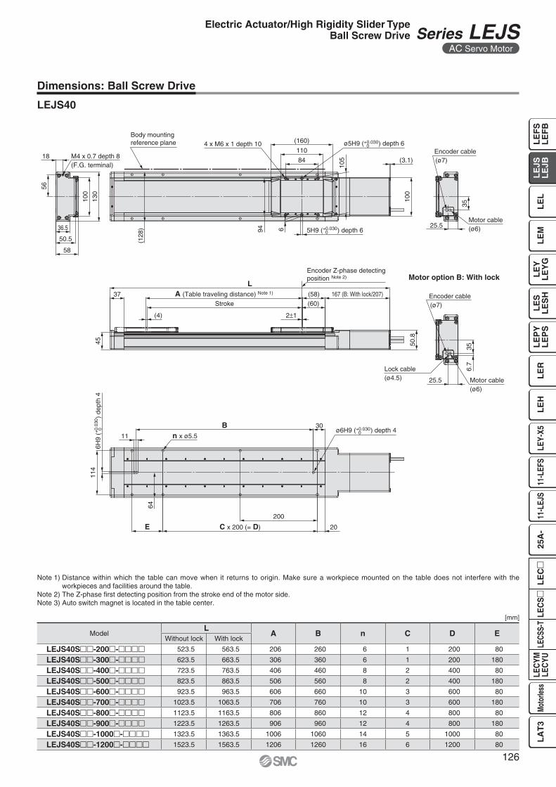
Dimensions: Ball Screw Drive
LEJS40
Note 1) Distance within which the table can move when it returns to origin. Make sure a workpiece mounted on the table does not interfere with the workpieces and facilities around the table.
Note 2) The Z-phase fi rst detecting position from the stroke end of the motor side.Note 3) Auto switch magnet is located in the table center.
[mm]
ModelL
A B n C D EWithout lock With lock
LEJS40S��-200�-���� 523.5 563.5 206 260 6 1 200 80
LEJS40S��-300�-���� 623.5 663.5 306 360 6 1 200 180
LEJS40S��-400�-���� 723.5 763.5 406 460 8 2 400 80
LEJS40S��-500�-���� 823.5 863.5 506 560 8 2 400 180
LEJS40S��-600�-���� 923.5 963.5 606 660 10 3 600 80
LEJS40S��-700�-���� 1023.5 1063.5 706 760 10 3 600 180
LEJS40S��-800�-���� 1123.5 1163.5 806 860 12 4 800 80
LEJS40S��-900�-���� 1223.5 1263.5 906 960 12 4 800 180
LEJS40S��-1000�-���� 1323.5 1363.5 1006 1060 14 5 1000 80
LEJS40S��-1200�-���� 1523.5 1563.5 1206 1260 16 6 1200 80
126
Electric Actuator/High Rigidity Slider TypeBall Screw Drive Series LEJS
AC Servo Motor
LE
FS
LE
FB
LE
LL
EJS
LE
JBL
EM
LE
YL
EY
GL
ES
LE
SH
LE
PY
LE
PS
LE
RL
EH
LEY-
X511
-LEF
S11
-LEJ
S25
A-
LEC
YMLE
CYU
LECS
S-T
LA
T3
Moto
rless
LEC
SL
EC
Motor option B: With lock
Motor cable(ø6)
79
+0.036 0ø8H9 ( ) depth 6+0.
036
08H
9 (
) d
epth
6
+0.030 06H9 ( ) depth 7
7
129
124
(3.1)
114
+0.030 0ø6H9 ( ) depth 7
(158
)M4 x 0.7 depth 8(F.G. terminal)25
68
160
124
73
63.5
49.5
Body mounting reference plane
4 x M8 x 1.25 depth 12
(172)
12290
C x 200 (= D)
200
25
140
n x ø6.8
B
13
30
47
E
35
47
Encoder cable(ø7)
Lock cable(ø4.5)
Motor cable(ø6)
Encoder cable(ø7)
35
6.7
(66)
(64)
58
39
(4)
Stroke
A (Table traveling distance) Note 1)
L
70
186 (B: With lock/226)
2 1
Encoder Z-phase detectingposition Note 2)
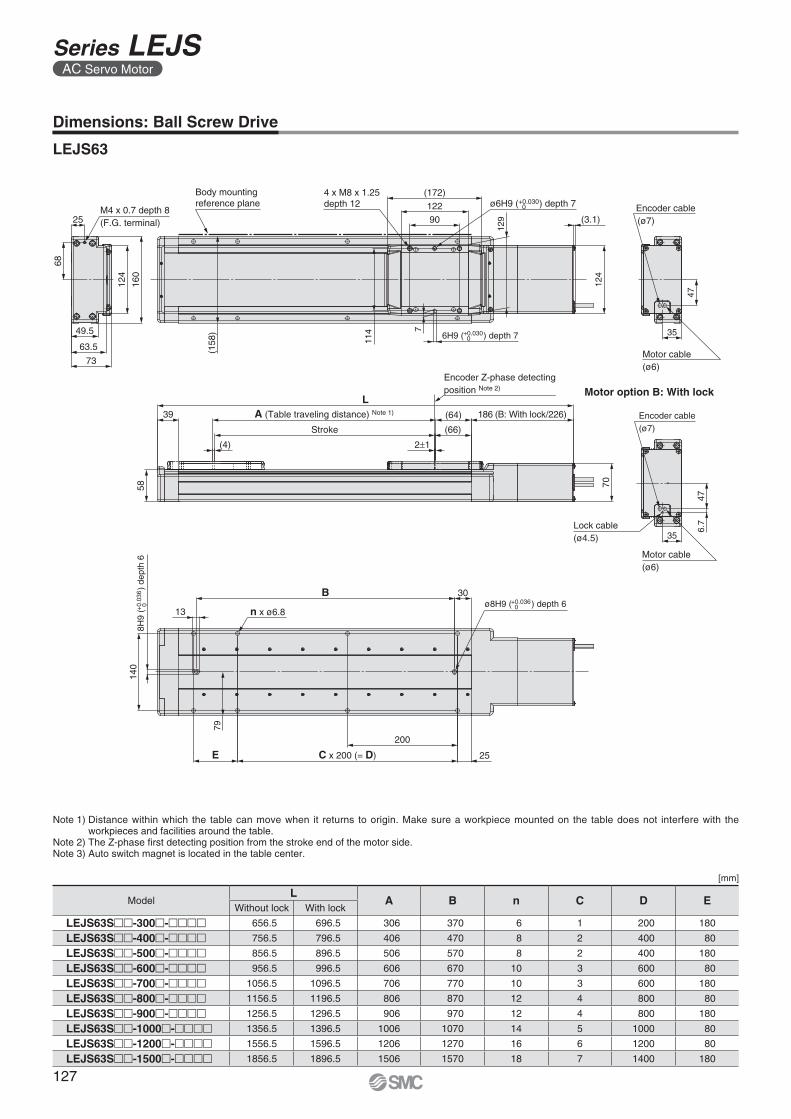
Dimensions: Ball Screw Drive
LEJS63
[mm]
Note 1) Distance within which the table can move when it returns to origin. Make sure a workpiece mounted on the table does not interfere with the workpieces and facilities around the table.
Note 2) The Z-phase fi rst detecting position from the stroke end of the motor side.Note 3) Auto switch magnet is located in the table center.
ModelL
A B n C D EWithout lock With lock
LEJS63S��-300�-���� 656.5 696.5 306 370 6 1 200 180
LEJS63S��-400�-���� 756.5 796.5 406 470 8 2 400 80
LEJS63S��-500�-���� 856.5 896.5 506 570 8 2 400 180
LEJS63S��-600�-���� 956.5 996.5 606 670 10 3 600 80
LEJS63S��-700�-���� 1056.5 1096.5 706 770 10 3 600 180
LEJS63S��-800�-���� 1156.5 1196.5 806 870 12 4 800 80
LEJS63S��-900�-���� 1256.5 1296.5 906 970 12 4 800 180
LEJS63S��-1000�-���� 1356.5 1396.5 1006 1070 14 5 1000 80
LEJS63S��-1200�-���� 1556.5 1596.5 1206 1270 16 6 1200 80
LEJS63S��-1500�-���� 1856.5 1896.5 1506 1570 18 7 1400 180
127
Series LEJSAC Servo Motor
How to Order
For auto switches, refer to pages 133 to 135.Compatible Driver
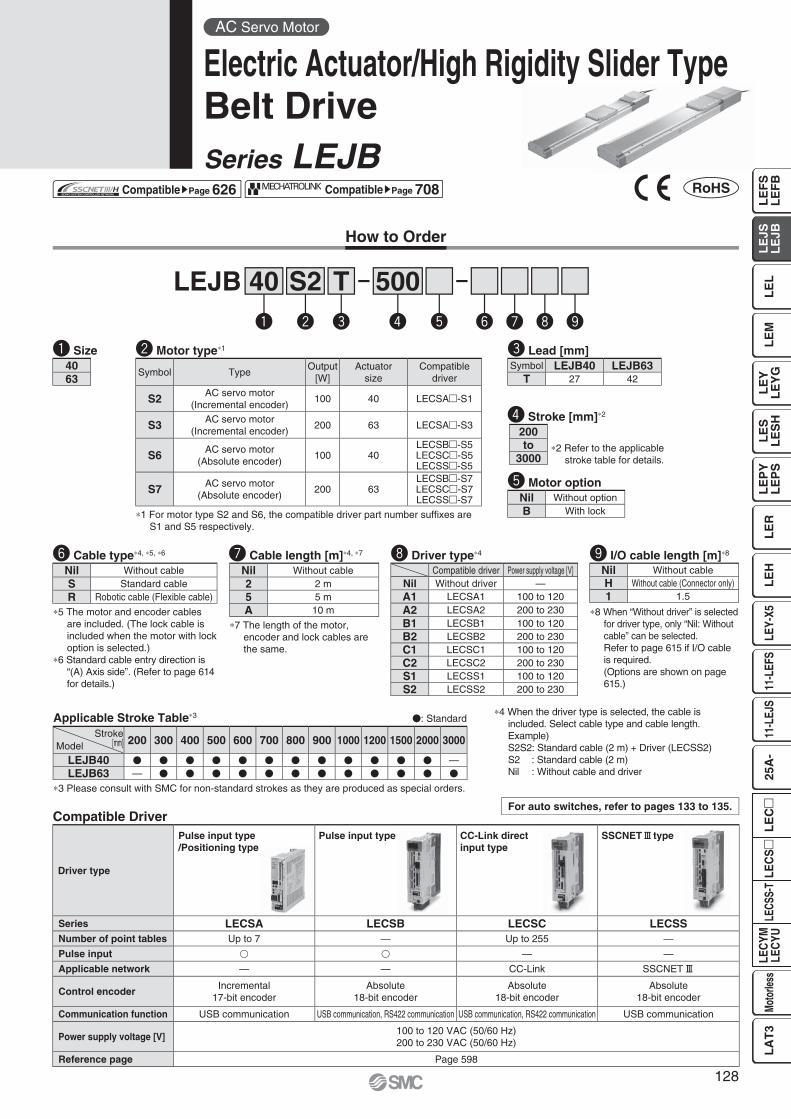
LEJB 40 500Tq w e r t y u i o
S2
Applicable Stroke Table∗3 �: Standard
∗3 Please consult with SMC for non-standard strokes as they are produced as special orders.
q Size e Lead [mm]
t Motor option
r Stroke [mm]∗2
∗5 The motor and encoder cables are included. (The lock cable is included when the motor with lock option is selected.)
∗6 Standard cable entry direction is “(A) Axis side”. (Refer to page 614 for details.)
∗7 The length of the motor, encoder and lock cables are the same.
y Cable type∗4, ∗5, ∗6 u Cable length [m]∗4, ∗7 i Driver type∗4
∗1 For motor type S2 and S6, the compatible driver part number suffi xes are S1 and S5 respectively.
w Motor type∗1
∗2 Refer to the applicable stroke table for details.
∗4 When the driver type is selected, the cable is included. Select cable type and cable length.Example)S2S2: Standard cable (2 m) + Driver (LECSS2)S2 : Standard cable (2 m)Nil : Without cable and driver
Symbol TypeOutput
[W]Actuator
sizeCompatible
driver
S2 AC servo motor(Incremental encoder)
100 40 LECSA�-S1
S3 AC servo motor(Incremental encoder)
200 63 LECSA�-S3
S6 AC servo motor(Absolute encoder)
100 40LECSB�-S5LECSC�-S5LECSS�-S5
S7 AC servo motor(Absolute encoder)
200 63LECSB�-S7LECSC�-S7LECSS�-S7
Compatible driver Power supply voltage [V]Nil Without driver —A1 LECSA1 100 to 120A2 LECSA2 200 to 230B1 LECSB1 100 to 120B2 LECSB2 200 to 230C1 LECSC1 100 to 120C2 LECSC2 200 to 230S1 LECSS1 100 to 120S2 LECSS2 200 to 230
Nil Without cableS Standard cableR Robotic cable (Flexible cable)
Nil Without cable2 2 m5 5 mA 10 m
200to
3000
Nil Without optionB With lock
Stroke[mm]Model 200 300 400 500 600 700 800 900 1000 1200 1500 2000 3000
LEJB40 � � � � � � � � � � � � —LEJB63 — � � � � � � � � � � � �
Symbol LEJB40 LEJB63T 27 42
4063
Driver type
Pulse input type/Positioning type
Pulse input type CC-Link directinput type
SSCNET# type
Series LECSA LECSB LECSC LECSSNumber of point tables Up to 7 — Up to 255 —
Pulse input � � — —
Applicable network — — CC-Link SSCNET#
Control encoderIncremental
17-bit encoderAbsolute
18-bit encoderAbsolute
18-bit encoderAbsolute
18-bit encoder
Communication function USB communication USB communication, RS422 communication USB communication, RS422 communication USB communication
Power supply voltage [V]100 to 120 VAC (50/60 Hz)200 to 230 VAC (50/60 Hz)
Reference page Page 598
o I/O cable length [m]∗8
Nil Without cableH Without cable (Connector only)1 1.5
∗8 When “Without driver” is selected for driver type, only “Nil: Without cable” can be selected.Refer to page 615 if I/O cable is required.(Options are shown on page 615.)
AC Servo Motor
Electric Actuator/High Rigidity Slider TypeBelt DriveSeries LEJB
CompatiblesPage 626 CompatiblesPage 708
128
LE
FS
LE
FB
LE
LL
EJS
LE
JBL
EM
LE
YL
EY
GL
ES
LE
SH
LE
PY
LE
PS
LE
RL
EH
LEY-
X511
-LEF
S11
-LEJ
S25
A-
LEC
YMLE
CYU
LECS
S-T
LA
T3
Moto
rless
LEC
SL
EC
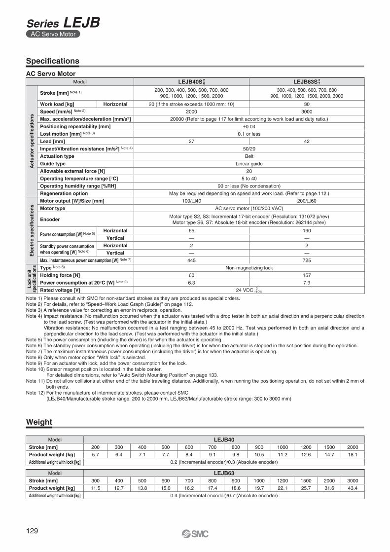
Specifi cations
Note 1) Please consult with SMC for non-standard strokes as they are produced as special orders.Note 2) For details, refer to “Speed–Work Load Graph (Guide)” on page 112.Note 3) A reference value for correcting an error in reciprocal operation.Note 4) Impact resistance: No malfunction occurred when the actuator was tested with a drop tester in both an axial direction and a perpendicular direction
to the lead screw. (Test was performed with the actuator in the initial state.)Vibration resistance: No malfunction occurred in a test ranging between 45 to 2000 Hz. Test was performed in both an axial direction and a perpendicular direction to the lead screw. (Test was performed with the actuator in the initial state.)
Note 5) The power consumption (including the driver) is for when the actuator is operating.Note 6) The standby power consumption when operating (including the driver) is for when the actuator is stopped in the set position during the operation.Note 7) The maximum instantaneous power consumption (including the driver) is for when the actuator is operating.Note 8) Only when motor option “With lock” is selected.Note 9) For an actuator with lock, add the power consumption for the lock.Note 10) Sensor magnet position is located in the table center.
For detailed dimensions, refer to “Auto Switch Mounting Position” on page 133.Note 11) Do not allow collisions at either end of the table traveling distance. Additionally, when running the positioning operation, do not set within 2 mm of
both ends.Note 12) For the manufacture of intermediate strokes, please contact SMC.
(LEJB40/Manufacturable stroke range: 200 to 2000 mm, LEJB63/Manufacturable stroke range: 300 to 3000 mm)
AC Servo MotorModel LEJB40S 2
6 LEJB63S 37
Act
uat
or
spec
ifi ca
tio
ns
Stroke [mm] Note 1) 200, 300, 400, 500, 600, 700, 800900, 1000, 1200, 1500, 2000
300, 400, 500, 600, 700, 800900, 1000, 1200, 1500, 2000, 3000
Work load [kg] Horizontal 20 (If the stroke exceeds 1000 mm: 10) 30
Speed [mm/s] Note 2) 2000 3000
Max. acceleration/deceleration [mm/s2] 20000 (Refer to page 117 for limit according to work load and duty ratio.)
Positioning repeatability [mm] ±0.04
Lost motion [mm] Note 3) 0.1 or less
Lead [mm] 27 42
Impact/Vibration resistance [m/s2] Note 4) 50/20
Actuation type Belt
Guide type Linear guide
Allowable external force [N] 20
Operating temperature range [°C] 5 to 40
Operating humidity range [%RH] 90 or less (No condensation)
Regeneration option May be required depending on speed and work load. (Refer to page 112.)
Ele
ctri
c sp
ecifi
cati
on
s
Motor output [W]/Size [mm] 100/�40 200/�60
Motor type AC servo motor (100/200 VAC)
EncoderMotor type S2, S3: Incremental 17-bit encoder (Resolution: 131072 p/rev)
Motor type S6, S7: Absolute 18-bit encoder (Resolution: 262144 p/rev)
Power consumption [W] Note 5)Horizontal 65 190
Vertical — —
Standby power consumptionwhen operating [W] Note 6)
Horizontal 2 2
Vertical — —
Max. instantaneous power consumption [W] Note 7) 445 725
Lock
uni
tsp
ecifi
catio
ns Type Note 8) Non-magnetizing lock
Holding force [N] 60 157
Power consumption at 20°C [W] Note 9) 6.3 7.9
Rated voltage [V] 24 VDC 0–10%
Weight
Model LEJB63Stroke [mm] 300 400 500 600 700 800 900 1000 1200 1500 2000 3000
Product weight [kg] 11.5 12.7 13.8 15.0 16.2 17.4 18.6 19.7 22.1 25.7 31.6 43.4
Additional weight with lock [kg] 0.4 (Incremental encoder)/0.7 (Absolute encoder)
Model LEJB40Stroke [mm] 200 300 400 500 600 700 800 900 1000 1200 1500 2000
Product weight [kg] 5.7 6.4 7.1 7.7 8.4 9.1 9.8 10.5 11.2 12.6 14.7 18.1
Additional weight with lock [kg] 0.2 (Incremental encoder)/0.3 (Absolute encoder)
129
Series LEJBAC Servo Motor
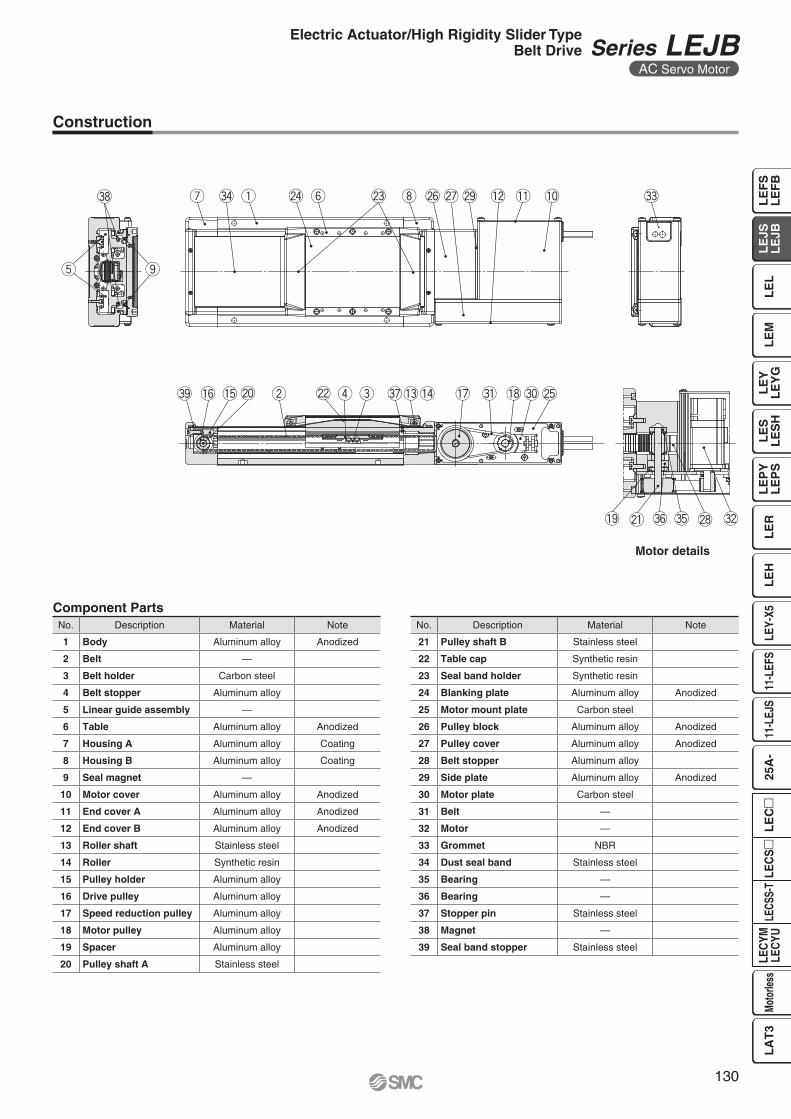
Motor details
Component Parts
Construction
No. Description Material Note
21 Pulley shaft B Stainless steel
22 Table cap Synthetic resin
23 Seal band holder Synthetic resin
24 Blanking plate Aluminum alloy Anodized
25 Motor mount plate Carbon steel
26 Pulley block Aluminum alloy Anodized
27 Pulley cover Aluminum alloy Anodized
28 Belt stopper Aluminum alloy
29 Side plate Aluminum alloy Anodized
30 Motor plate Carbon steel
31 Belt —
32 Motor —
33 Grommet NBR
34 Dust seal band Stainless steel
35 Bearing —
36 Bearing —
37 Stopper pin Stainless steel
38 Magnet —
39 Seal band stopper Stainless steel
No. Description Material Note
1 Body Aluminum alloy Anodized
2 Belt —
3 Belt holder Carbon steel
4 Belt stopper Aluminum alloy
5 Linear guide assembly —
6 Table Aluminum alloy Anodized
7 Housing A Aluminum alloy Coating
8 Housing B Aluminum alloy Coating
9 Seal magnet —
10 Motor cover Aluminum alloy Anodized
11 End cover A Aluminum alloy Anodized
12 End cover B Aluminum alloy Anodized
13 Roller shaft Stainless steel
14 Roller Synthetic resin
15 Pulley holder Aluminum alloy
16 Drive pulley Aluminum alloy
17 Speed reduction pulley Aluminum alloy
18 Motor pulley Aluminum alloy
19 Spacer Aluminum alloy
20 Pulley shaft A Stainless steel
130
Electric Actuator/High Rigidity Slider TypeBelt Drive Series LEJB
AC Servo Motor
LE
FS
LE
FB
LE
LL
EJS
LE
JBL
EM
LE
YL
EY
GL
ES
LE
SH
LE
PY
LE
PS
LE
RL
EH
LEY-
X511
-LEF
S11
-LEJ
S25
A-
LEC
YMLE
CYU
LECS
S-T
LA
T3
Moto
rless
LEC
SL
EC
Motor option B: With lock
+0.030 0ø6H9 ( ) depth 4+
0.03
0 0
6H9
(
)
dep
th 4
64
(128
) +0.030 05H9 ( ) depth 6
+0.030 0ø5H9 ( ) depth 6
9458
50.5
36.5
130
100
56
M4 x 0.7 depth 8(F.G. terminal)
18
Body mounting reference plane
84
110
(160)4 x M6 x 1 depth 10
105 26
44
3.5
121
(3.1
)(3
.1)
6
Encoder cable(ø7)
Motor cable(ø6)
E200
20C x 200 (= D)
114
11 n x ø5.5
B 30
45
37
(4)
Stroke
A (Table traveling distance) Note 1)
L
2 1
(60)
(58)
Encoder Z-phase detectingposition Note 2)
185.5
50.8 93
170
3.5
26
Encoder cable(ø7)
Lock cable(ø4.5)
Motor cable(ø6)
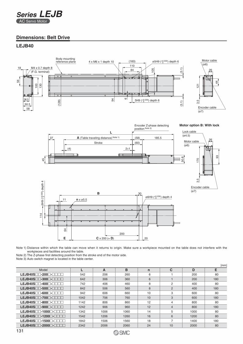
Dimensions: Belt Drive
LEJB40
Note 1) Distance within which the table can move when it returns to origin. Make sure a workpiece mounted on the table does not interfere with the workpieces and facilities around the table.
Note 2) The Z-phase fi rst detecting position from the stroke end of the motor side.Note 3) Auto switch magnet is located in the table center.
[mm]
Model L A B n C D ELEJB40S��-200�-���� 542 206 260 6 1 200 80
LEJB40S��-300�-���� 642 306 360 6 1 200 180
LEJB40S��-400�-���� 742 406 460 8 2 400 80
LEJB40S��-500�-���� 842 506 560 8 2 400 180
LEJB40S��-600�-���� 942 606 660 10 3 600 80
LEJB40S��-700�-���� 1042 706 760 10 3 600 180
LEJB40S��-800�-���� 1142 806 860 12 4 800 80
LEJB40S��-900�-���� 1242 906 960 12 4 800 180
LEJB40S��-1000�-���� 1342 1006 1060 14 5 1000 80
LEJB40S��-1200�-���� 1542 1206 1260 16 6 1200 80
LEJB40S��-1500�-���� 1842 1506 1560 18 7 1400 180
LEJB40S��-2000�-���� 2342 2006 2060 24 10 2000 80
131
Series LEJBAC Servo Motor
Motor option B:With lock
+0.036 0ø8H9 ( ) depth 6+
0.03
6 0
8H9
(
)
dep
th 6
(158
) +0.030 06H9 ( ) depth 7
+0.030 0ø6H9 ( ) depth 7
114
73
63.5
49.5
160
124
68
25M4 x 0.7 depth 8(F.G. terminal)
Body mounting reference plane (172)
12290
4 x M8 x 1.25 depth 12
129
(3.1
) 413
7
45
35
Motor cable(ø6)
Encoder cable(ø7)
(3.1
)
7
58
39
(4)
Stroke
A (Table traveling distance) Note 1)
L233.5
Encoder Z-phase detectingposition Note 2)
2 1
(66)
(64)
70
177
85
4
Motor cable(ø6) 35
Encoder cable(ø7)
Lock cable(ø4.5)
140
B
n x ø6.813
30
E C x 200 (= D)
200
25
79
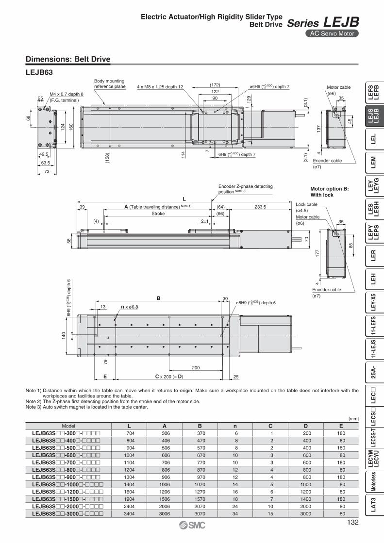
Dimensions: Belt Drive
LEJB63
[mm]
Note 1) Distance within which the table can move when it returns to origin. Make sure a workpiece mounted on the table does not interfere with the workpieces and facilities around the table.
Note 2) The Z-phase fi rst detecting position from the stroke end of the motor side.Note 3) Auto switch magnet is located in the table center.
Model L A B n C D ELEJB63S��-300�-���� 704 306 370 6 1 200 180
LEJB63S��-400�-���� 804 406 470 8 2 400 80
LEJB63S��-500�-���� 904 506 570 8 2 400 180
LEJB63S��-600�-���� 1004 606 670 10 3 600 80
LEJB63S��-700�-���� 1104 706 770 10 3 600 180
LEJB63S��-800�-���� 1204 806 870 12 4 800 80
LEJB63S��-900�-���� 1304 906 970 12 4 800 180
LEJB63S��-1000�-���� 1404 1006 1070 14 5 1000 80
LEJB63S��-1200�-���� 1604 1206 1270 16 6 1200 80
LEJB63S��-1500�-���� 1904 1506 1570 18 7 1400 180
LEJB63S��-2000�-���� 2404 2006 2070 24 10 2000 80
LEJB63S��-3000�-���� 3404 3006 3070 34 15 3000 80
132
Electric Actuator/High Rigidity Slider TypeBelt Drive Series LEJB
AC Servo Motor
LE
FS
LE
FB
LE
LL
EJS
LE
JBL
EM
LE
YL
EY
GL
ES
LE
SH
LE
PY
LE
PS
LE
RL
EH
LEY-
X511
-LEF
S11
-LEJ
S25
A-
LEC
YMLE
CYU
LECS
S-T
LA
T3
Moto
rless
LEC
SL
EC
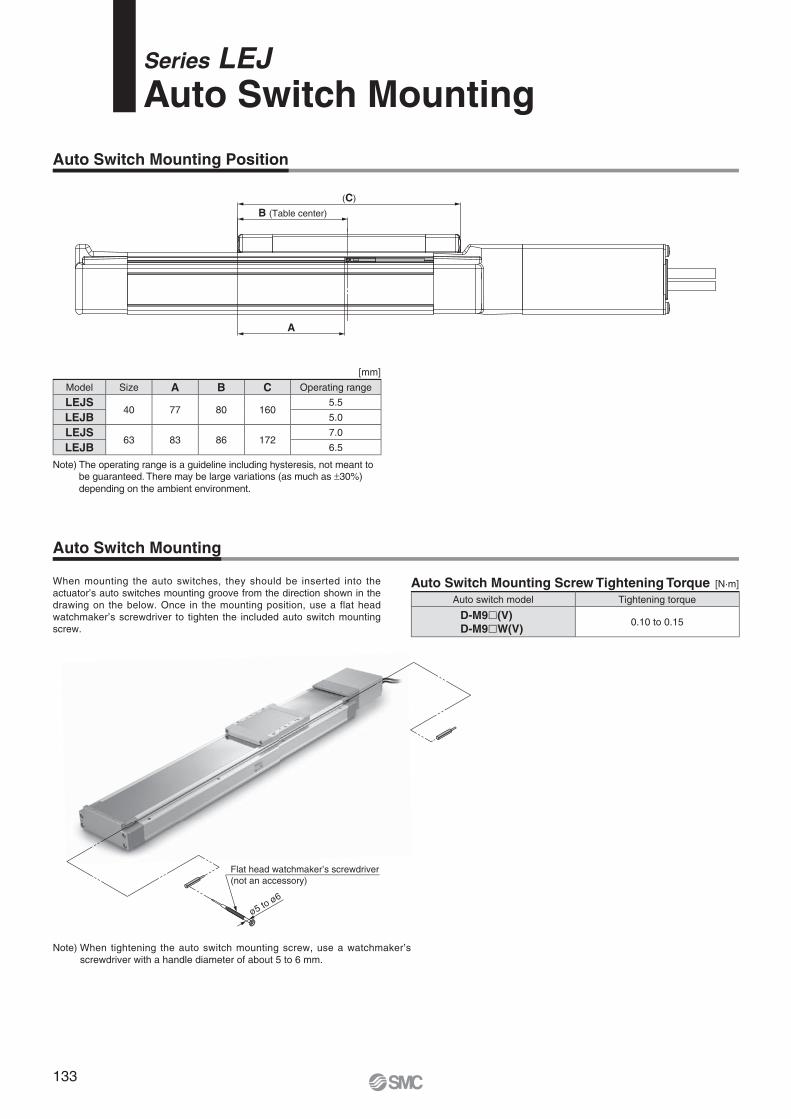
Model Size A B C Operating range
LEJS40 77 80 160
5.5
LEJB 5.0
LEJS63 83 86 172
7.0
LEJB 6.5
Note) The operating range is a guideline including hysteresis, not meant to be guaranteed. There may be large variations (as much as ±30%) depending on the ambient environment.
Auto Switch Mounting Screw Tightening Torque [N·m]
Auto switch model Tightening torque
D-M9�(V)D-M9�W(V)
0.10 to 0.15
A
(C)
B (Table center)
When mounting the auto switches, they should be inserted into the actuator’s auto switches mounting groove from the direction shown in the drawing on the below. Once in the mounting position, use a flat head watchmaker’s screwdriver to tighten the included auto switch mounting screw.
Note) When tightening the auto switch mounting screw, use a watchmaker’s screwdriver with a handle diameter of about 5 to 6 mm.
ø5 to ø6
Flat head watchmaker’s screwdriver (not an accessory)
[mm]
Series LEJAuto Switch Mounting
Auto Switch Mounting Position
Auto Switch Mounting
133
2.7
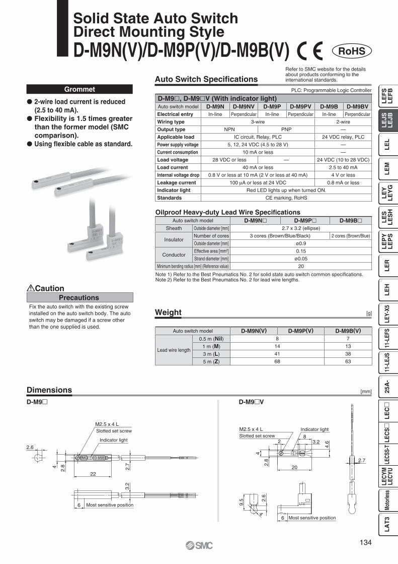
22
2.6
4
2.8
3.2
6
M2.5 x 4 LSlotted set screw
Indicator light
Most sensitive position
M2.5 x 4 L Indicator lightSlotted set screw
Most sensitive position4
2.6
9.5
2.7
4.62
20
2.8
83.2
4
6
Auto Switch Specifi cations
Weight
Dimensions
PrecautionsCaution
Fix the auto switch with the existing screw installed on the auto switch body. The auto switch may be damaged if a screw other than the one supplied is used.
[g]
Grommet
Note 1) Refer to the Best Pneumatics No. 2 for solid state auto switch common specifi cations.Note 2) Refer to the Best Pneumatics No. 2 for lead wire lengths.
D-M9� D-M9�V
� 2-wire load current is reduced (2.5 to 40 mA).
� Flexibility is 1.5 times greater than the former model (SMC comparison).
� Using fl exible cable as standard.
[mm]
Oilproof Heavy-duty Lead Wire Specifi cations
RoHS
Solid State Auto SwitchDirect Mounting StyleD-M9N(V)/D-M9P(V)/D-M9B(V)
PLC: Programmable Logic Controller
Refer to SMC website for the details about products conforming to the international standards.
D-M9�, D-M9�V (With indicator light)Auto switch model D-M9N D-M9NV D-M9P D-M9PV D-M9B D-M9BVElectrical entry In-line Perpendicular In-line Perpendicular In-line Perpendicular
Wiring type 3-wire 2-wire
Output type NPN PNP —
Applicable load IC circuit, Relay, PLC 24 VDC relay, PLC
Power supply voltage 5, 12, 24 VDC (4.5 to 28 V) —
Current consumption 10 mA or less —
Load voltage 28 VDC or less — 24 VDC (10 to 28 VDC)
Load current 40 mA or less 2.5 to 40 mA
Internal voltage drop 0.8 V or less at 10 mA (2 V or less at 40 mA) 4 V or less
Leakage current 100 μA or less at 24 VDC 0.8 mA or less
Indicator light Red LED lights up when turned ON.
Standards CE marking, RoHS
Auto switch model D-M9N� D-M9P� D-M9B�Sheath Outside diameter [mm] 2.7 x 3.2 (ellipse)
InsulatorNumber of cores 3 cores (Brown/Blue/Black) 2 cores (Brown/Blue)
Outside diameter [mm] ø0.9
ConductorEffective area [mm2] 0.15
Strand diameter [mm] ø0.05
Minimum bending radius [mm] (Reference value) 20
Auto switch model D-M9N(V) D-M9P(V) D-M9B(V)
Lead wire length
0.5 m (Nil) 8 7
1 m (M) 14 13
3 m (L) 41 38
5 m (Z) 68 63
134
LE
FS
LE
FB
LE
LL
EJS
LE
JBL
EM
LE
YL
EY
GL
ES
LE
SH
LE
PY
LE
PS
LE
RL
EH
LEY-
X511
-LEF
S11
-LEJ
S25
A-
LEC
YMLE
CYU
LECS
S-T
LA
T3
Moto
rless
LEC
SL
EC
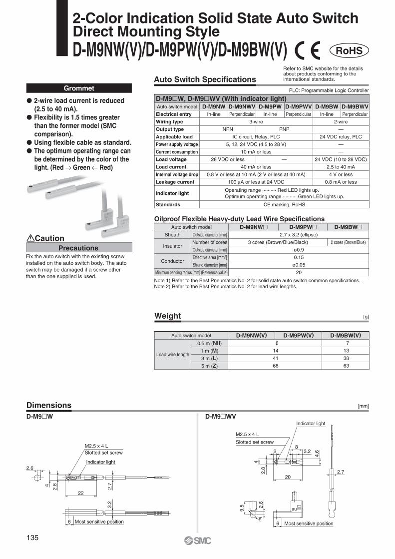
M2.5 x 4 LSlotted set screw
Indicator light
Most sensitive position
2.7
22
2.6
4
2.8
3.2
6
M2.5 x 4 L
Indicator light
Slotted set screw
Most sensitive position4
2.6
9.5
2.8
4.6
4
20
28
3.2
6
2.7
Auto Switch Specifi cations
Weight
Dimensions
[g]
[mm]
Grommet
Note 1) Refer to the Best Pneumatics No. 2 for solid state auto switch common specifi cations.Note 2) Refer to the Best Pneumatics No. 2 for lead wire lengths.
� 2-wire load current is reduced (2.5 to 40 mA).
� Flexibility is 1.5 times greater than the former model (SMC comparison).
� Using fl exible cable as standard.� The optimum operating range can
be determined by the color of the light. (Red → Green ← Red)
D-M9�W D-M9�WV
RoHS
Oilproof Flexible Heavy-duty Lead Wire Specifi cations
2-Color Indication Solid State Auto SwitchDirect Mounting StyleD-M9NW(V)/D-M9PW(V)/D-M9BW(V)
PrecautionsCaution
Fix the auto switch with the existing screw installed on the auto switch body. The auto switch may be damaged if a screw other than the one supplied is used.
Refer to SMC website for the details about products conforming to the international standards.
PLC: Programmable Logic Controller
D-M9�W, D-M9�WV (With indicator light)Auto switch model D-M9NW D-M9NWV D-M9PW D-M9PWV D-M9BW D-M9BWVElectrical entry In-line Perpendicular In-line Perpendicular In-line Perpendicular
Wiring type 3-wire 2-wire
Output type NPN PNP —
Applicable load IC circuit, Relay, PLC 24 VDC relay, PLC
Power supply voltage 5, 12, 24 VDC (4.5 to 28 V) —
Current consumption 10 mA or less —
Load voltage 28 VDC or less — 24 VDC (10 to 28 VDC)
Load current 40 mA or less 2.5 to 40 mA
Internal voltage drop 0.8 V or less at 10 mA (2 V or less at 40 mA) 4 V or less
Leakage current 100 μA or less at 24 VDC 0.8 mA or less
Indicator lightOperating range .......... Red LED lights up.Optimum operating range .......... Green LED lights up.
Standards CE marking, RoHS
Auto switch model D-M9NW� D-M9PW� D-M9BW�Sheath Outside diameter [mm] 2.7 x 3.2 (ellipse)
InsulatorNumber of cores 3 cores (Brown/Blue/Black) 2 cores (Brown/Blue)
Outside diameter [mm] ø0.9
ConductorEffective area [mm2] 0.15
Strand diameter [mm] ø0.05
Minimum bending radius [mm] (Reference value) 20
Auto switch model D-M9NW(V) D-M9PW(V) D-M9BW(V)
Lead wire length
0.5 m (Nil) 8 7
1 m (M) 14 13
3 m (L) 41 38
5 m (Z) 68 63
135
Design Handling
Caution Caution
Warning
1. Do not apply a load in excess of the specifi cation limits.Select a suitable actuator by work load and allowable moment. If the product is used outside of the specifi cation limits, the eccentric load applied to the guide will be excessive and have adverse effects such as creating play on the guide, degrading accuracy and shortening the life of the product.
2. Do not use the product in applications where excessive external force or impact force is applied to it.The product can be damaged.The components including the motor are manufactured to precise tolerances. So that even a slight deformation may cause a malfunction or seizure.
Selection
1. Do not increase the speed in excess of the specifi cation limits.Select a suitable actuator by the relationship of the allowable work load and speed, and the allowable speed of each stroke. If the product is used outside of the specifi cation limits, it will have adverse effects such as creating noise, degrading accuracy and shortening the life of the product.
2. When the product repeatedly cycles with partial strokes (100 mm or less), lubrication can run out. Operate it at a full stroke at least once a day or every a thousand cycles.
3. When external force is applied to the table, it is necessary to add external force to the work load as the total carried load for the sizing.When a cable duct or fl exible moving tube is attached to the actuator, the sliding resistance of the table increases and may lead to operational failure of the product.
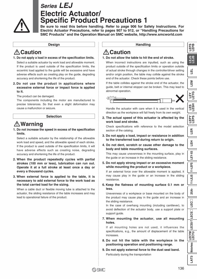
1. Do not allow the table to hit the end of stroke.When incorrect instructions are inputted, such as using the product outside of the specifi cation limits or operation outside of actual stroke through changes in the controller/driver setting and/or origin position, the table may collide against the stroke end of the actuator. Check these points before use.
If the table collides against the stroke end of the actuator, the guide, belt or internal stopper can be broken. This may lead to abnormal operation.
Handle the actuator with care when it is used in the vertical direction as the workpiece will fall freely from its own weight.
2. The actual speed of this actuator is affected by the work load and stroke.Check specifi cations with reference to the model selection section of the catalog.
3. Do not apply a load, impact or resistance in addition to the transferred load during return to origin.
4. Do not dent, scratch or cause other damage to the body and table mounting surfaces.This may cause unevenness in the mounting surface, play in the guide or an increase in the sliding resistance.
5. Do not apply strong impact or an excessive moment while mounting the product or a workpiece.If an external force over the allowable moment is applied, it may cause play in the guide or an increase in the sliding resistance.
6. Keep the fl atness of mounting surface 0.1 mm or less.Unevenness of a workpiece or base mounted on the body of the product may cause play in the guide and an increase in the sliding resistance.In the case of overhang mounting (including cantilever), to avoid defl ection of the actuator body, use a support plate or support guide.
7. When mounting the actuator, use all mounting holes.If all mounting holes are not used, it influences the specifi cations, e.g., the amount of displacement of the table increases.
8. Do not hit the table with the workpiece in the positioning operation and positioning range.
9. Do not apply external force to the dust seal band.Particularly during the transportation
Series LEJ Electric Actuator/Specifi c Product Precautions 1Be sure to read this before handling. Refer to page 906 for Safety Instructions. For Electric Actuator Precautions, refer to pages 907 to 912, or “Handling Precautions for SMC Products” and the Operation Manual on SMC website, http://www.smcworld.com
136
LE
FS
LE
FB
LE
LL
EJS
LE
JBL
EM
LE
YL
EY
GL
ES
LE
SH
LE
PY
LE
PS
LE
RL
EH
LEY-
X511
-LEF
S11
-LEJ
S25
A-
LEC
YMLE
CYU
LECS
S-T
LA
T3
Moto
rless
LEC
SL
EC
L
øAL
Body mounting reference plane
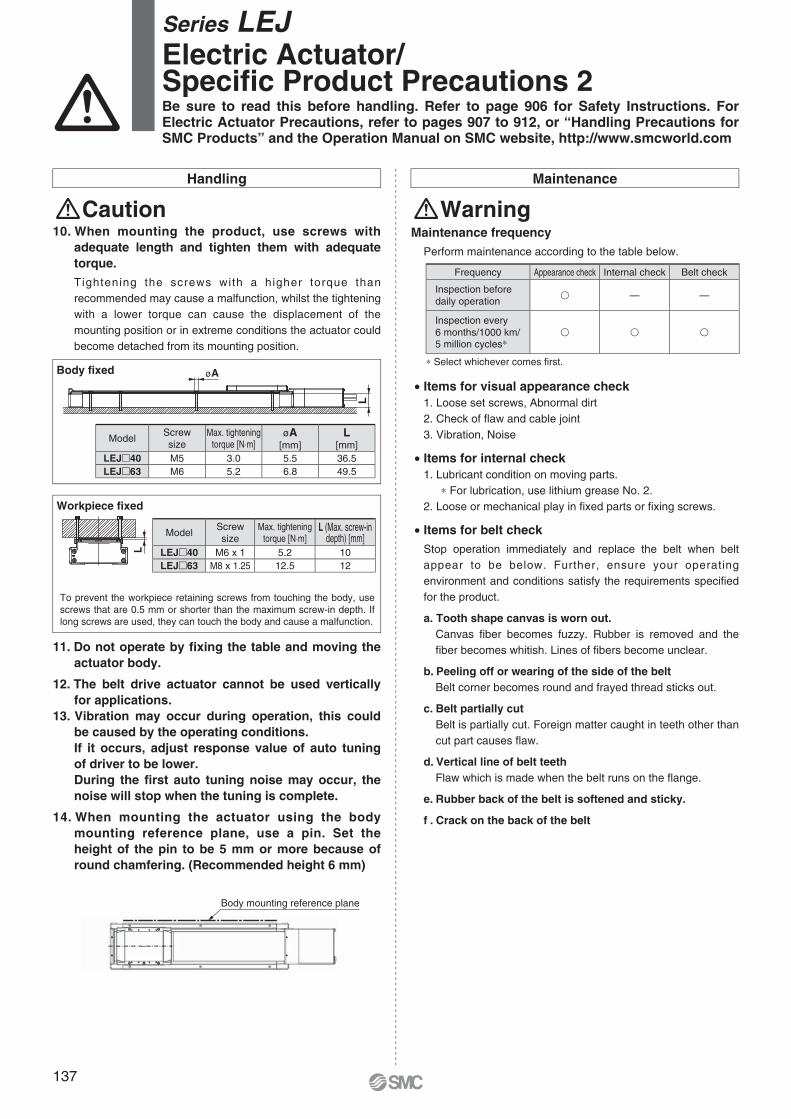
To prevent the workpiece retaining screws from touching the body, use screws that are 0.5 mm or shorter than the maximum screw-in depth. If long screws are used, they can touch the body and cause a malfunction.
Workpiece fi xed
Body fi xed
Handling Maintenance
Caution10. When mounting the product, use screws with
adequate length and tighten them with adequate torque.Tightening the screws with a higher torque than recommended may cause a malfunction, whilst the tightening with a lower torque can cause the displacement of the mounting position or in extreme conditions the actuator could become detached from its mounting position.
11. Do not operate by fi xing the table and moving the actuator body.
12. The belt drive actuator cannot be used vertically for applications.
13. Vibration may occur during operation, this could be caused by the operating conditions.If it occurs, adjust response value of auto tuning of driver to be lower.During the fi rst auto tuning noise may occur, the noise will stop when the tuning is complete.
14. When mounting the actuator using the body mounting reference plane, use a pin. Set the height of the pin to be 5 mm or more because of round chamfering. (Recommended height 6 mm)
Maintenance frequencyPerform maintenance according to the table below.
• Items for visual appearance check1. Loose set screws, Abnormal dirt2. Check of fl aw and cable joint3. Vibration, Noise
• Items for internal check1. Lubricant condition on moving parts.
∗ For lubrication, use lithium grease No. 2.2. Loose or mechanical play in fi xed parts or fi xing screws.
• Items for belt checkStop operation immediately and replace the belt when belt appear to be below. Further, ensure your operating environment and conditions satisfy the requirements specifi ed for the product.
a. Tooth shape canvas is worn out.Canvas fi ber becomes fuzzy. Rubber is removed and the fi ber becomes whitish. Lines of fi bers become unclear.
b. Peeling off or wearing of the side of the beltBelt corner becomes round and frayed thread sticks out.
c. Belt partially cutBelt is partially cut. Foreign matter caught in teeth other than cut part causes fl aw.
d. Vertical line of belt teethFlaw which is made when the belt runs on the fl ange.
e. Rubber back of the belt is softened and sticky.
f . Crack on the back of the belt
∗ Select whichever comes fi rst.
Warning
Series LEJ Electric Actuator/Specifi c Product Precautions 2Be sure to read this before handling. Refer to page 906 for Safety Instructions. For Electric Actuator Precautions, refer to pages 907 to 912, or “Handling Precautions for SMC Products” and the Operation Manual on SMC website, http://www.smcworld.com
Frequency Appearance check Internal check Belt check
Inspection before daily operation
� — —
Inspection every6 months/1000 km/5 million cycles∗
� � �
ModelScrewsize
Max. tighteningtorque [N⋅m]
øA[mm]
L[mm]
LEJ�40 M5 3.0 5.5 36.5LEJ�63 M6 5.2 6.8 49.5
ModelScrewsize
Max. tighteningtorque [N⋅m]
L (Max. screw-indepth) [mm]
LEJ�40 M6 x 1 5.2 10LEJ�63 M8 x 1.25 12.5 12
137