electric shower - gainsborough showers the start/stop button, the flow control lets in the water. if...
TRANSCRIPT

E L E C T R I C S H O W E R
A Step by StepGuide to Installing
and Using your shower
Please leave with the user
Service enquiries: 01959 560760
Part No. GBH004 Issue 3

2
1. SAFETY
1.1 USER SAFETY INFORMATIONWARNINGAlways check showering temperaturebefore stepping into the shower. It willtake approximately 20 seconds to reacha stable temperature.
1.1.1 Products manufactured byGainsborough comply with British andEuropean Standards, are safe and withoutrisk provided they are installed, used andmaintained in good working order inaccordance with our instructions andrecommendations.1.1.2 This product contains a two stagethermal cut-out device. The first stageis self-resetting and operates in extremelylow flow conditions when outlet temperaturecan become excessive. The second stageis permanent and operates to prevent theunit becoming dangerously hot. If the secondstage operates, the shower must bereplaced.1.1.3 In addition to the 2 stage thermal cutout, this shower also contains a scaldprotection device. If a very low flow isselected by the user the scald protectiondevice will automatically add flow through
the heater to reduce the outlet temperature.1.1.4 For safety purposes, this shower hasa phased shut off. Water will continue to runfor a few seconds after switching off todissipate any residual heat from the heatexchanger.1.1.5 DO NOT operate the shower unit if itis frozen, or suspected of being frozen -refer to troubleshooting page 15.1.1.6 DO NOT operate the shower unit ifthe spray head or spray hose becomesdamaged.1.1.7 DO NOT restrict flow out of theshower by placing the spray head in directcontact with your body.1.1.8 DO NOT operate the shower unit ifwater ceases to flow during use.1.1.9 DO NOT operate the shower unit ifwater has entered the inside of the showerunit because of an incorrectly fitted cover.1.1.10 DO NOT operate the shower unit if itis damaged.1.1.11 The shower head and spray plateand cartridge must be cleaned regularlywith descalant to remove scale and debris,otherwise restrictions to the flow of theshower unit will result in higher temperaturesand could also cause the Pressure ReliefDevice (PRD) in the shower unit to operate.
ALL ELECTRIC SHOWERS MUST BE INSTALLED BY A QUALIFIED PERSON FOLLOWING THE LATEST REVISIONOF BS7671 (WIRING REGULATIONS) AND CERTIFIED TO BUILDING REGULATIONS. THE INSTALLATION MUSTALSO COMPLY WITH THE BUILDING REGULATIONS PART P AND THE WATER REGULATIONS. WHERE THEREIS A NEW INSTALLATION, OR A REPLACEMENT PRODUCT IS NOT IDENTICAL TO THE ONE BEING REPLACED,THE CABLE SIZES, CIRCUIT PROTECTIVE DEVICES, BONDING AND OTHER REQUIREMENTS OF THE BUILDINGREGULATIONS MUST BE ASSESSED BY A (REGISTERED) QUALIFIED AND COMPETENT ELECTRICIAN, WHOSHOULD CARRY OUT THE INSTALLATION TAKING INTO ACCOUNT THE SITE CONDITIONS (see Table A - Page 7).
ContentsSection 1 Safety1.1 User Safety Information ................. 21.2 General Safety .............................. 31.3 Electrical Safety ............................. 31.4 Plumbing Safety ............................ 3Section 2 Introduction2.1 How the Shower Works ................. 42.2 Shower Components ..................... 42.3 Pack Contents ............................... 4Section 3 Specification3.1 Technical Specification .................. 53.2 Standards and Approvals .............. 5Section 4 Site Requirements4.1 Water Requirements ...................... 5
4.2 Electrical Requirements ................. 54.3 Siting Considerations ..................... 74.4 Pressure Relief Device (PRD) ....... 84.5 Inlet fittings .................................... 8Section 5 Fitting the Shower5.1 Preparation .................................... 95.2 Cable and Pipe Entry Options ........ 95.3 Mounting the Shower ..................... 95.4 Cable Entry .................................. 115.5 Pipe Entry .................................... 115.6 Plumbing ..................................... 115.7 Wiring .......................................... 125.8 Fitting the Cover .......................... 12Section 6 Commissioning6.1 Commissioning Tests .................. 13
Section 7 Operator Instructions7.1 To Turn On & Set Temperature ... 147.2 To Turn Off .................................. 14Section 8 Maintenance8.1 Cleaning the Handset .................. 148.2 Inspection .................................... 148.3 Cleaning the Filter ....................... 14Section 9 Fault Finding ..................... 15Section 10 Guarantee and Service Policy 1610.1 Environmental Information ........... 16
3
1.1.12 The handset and shower hosesupplied are manufactured specifically tomatch the performance of the shower.Should either of these items requirereplacement you should contact CustomerService Department for help and advice.The use of unapproved components thatmay be of similar appearance maycompromise both performance and safetyand possibly result in damage not coveredby the warranty terms.1.1.13 This appliance is not intended foruse by persons (including children) withreduced physical, sensory or mentalcapabilities or lack of experience andknowledge unless they have been giveninitial supervision or instruction concerningthe use of the appliance by a personresponsible for their safety.Children should be supervised to ensurethat they do not play with the appliance.1.1.14 Soap, shampoo or shower gel mustnot be placed on top of the shower unit.1.1.15 The shower unit must be switchedoff at the isolating switch when not in use.
1.2 GENERAL SAFETY1.2.1 Read ALL of these instructionsBEFORE fitting the shower, the end usermust retain them for later use.1.2.2 Switch off (isolate) electrical andwater supplies BEFORE proceeding withthe installation or carrying out servicing.1.2.3 The shower unit must be mountedon a flat and even finished wall surface ontop of the tiles (when applicable). DO NOTtile up to shower unit after fixing to wall.1.2.4 This product is not suitable formounting into steam rooms or steamcubicles.1.2.5 Only use designated entry points forcable and pipe. Failure to do so willcompromise safety.
1.3 ELECTRICAL SAFETY1.3.1 All electrical maintenance/repairs/installation to the shower to be carried outby a qualified person. The installation shouldbe certified to building regulations.1.3.2 Before fitting the shower unit,determine that the electricity supply is
adequate; if in doubt, contact a competentelectrician.1.3.3 If upgrading to a higher kW shower, itis essential to ensure that the electrical circuit,including the wiring and isolating switchesare adequate for the increased load.1.3.4 It is advisable that, in the interests ofsafety, the shower and its electricalinstallation is checked by a competentelectrician, at least every two years.1.3.5 The installation must comply with BS7671 ‘Requirements for ElectricalInstallations’ (IEE Wiring Regulations).1.3.6 This shower unit must be earthed.1.3.7 Ensure all electrical connections aretight to prevent overheating.1.3.8 Fuses and circuit breakers do notgive protection against electric shock.1.3.9 To enhance electrical safety, a 30mAresidual current device (RCD) should beinstalled in all electric shower circuits. Thismay be part of the consumer unit, or aseparate unit.1.3.10 Other electrical equipment e.g.extractor fans, must not be connected to theshower or its supply circuit.
1.4 PLUMBING SAFETY1.4.1 All plumbing maintenance/repairs/installation to the shower to be carried outby a qualified person.1.4.2 The plumbing installation mustcomply with Water Regulations/Water Bye-laws.1.4.3 The supply pipe must be flushed toclear debris before connecting to the showerunit.1.4.4 DO NOT solder pipes or fittings within300mm of the shower unit, as heat transfercan damage components.1.4.5 DO NOT fit any form of outlet flowcontrol (e.g. a tap) as the outlet acts as avent for the heater.1.4.6 DO NOT use excessive force whenmaking connections to the flexible hose orspray head, finger tightness is sufficient.1.4.7 All plumbing connections must becompleted before making the electricalconnections.1.4.8 Ensure water pressure does notexceed the rating of the shower unit.

4
2. INTRODUCTION
2.1 HOW THE SHOWER WORKS2.1.1 When the user starts the shower bypressing the start/stop button, the flowcontrol lets in the water. If there is sufficientwater pressure, the pressure switch will turnon the heating elements.2.1.2 The element in the tank will start toheat the water and this takes typically 10-20seconds.2.1.3 By controlling the flow rate of waterover the heating elements, it will be warmedup to the correct temperature. Reducingthe flow rate will increase the watertemperature and vice versa.2.1.4 The following variables can affectthe shower temperature once it has beenset:-
Incoming water temperature.Incoming water pressure.Mains electrical voltage.
�������������
���� ��������
��������������
�����������
��������������
������������������
� �
Fig. 1 Schematic of Shower
Fig. 2 Shower components
2.2 SHOWER COMPONENTS
2.3 PACK CONTENTSThe shower carton contains:-Shower unit, knob, badge and rail.Shower fitting instructions and template.Accessory kit with fitting instructions.Note:- Screws and wall plugs are NOT supplied.

5
3. SPECIFICATIONDue to continuous improvement andupdating, specifications may be alteredwithout prior notice.
3.1 TECHNICAL SPECIFICATION3.1.1 ElectricalNominal Power Rating at 240V8.5kW - (40A MCB rating)9.5kW - (40A MCB rating)10.5kW - (45A or 50A MCB rating)
Nominal Power Rating at 230V7.8kW - (40A MCB rating)8.7kW - (40A MCB rating)9.6kW - (45A or 50A MCB rating)
3.1.2 WaterMinimum maintained running pressurerequired is 0.09MPa (0.9bar) and themaximum static pressure for the product is1.0 MPa (10.0bar). If the pressure is belowthe minimum stated, contact the local waterauthority.Inlet connection - 15mm diameter push fitconnection.Outlet connection - ½” BSP male thread.Dimensions - see template.
3.1.3 Entry Points
4. SITE REQUIREMENTS
4.1 WATER REQUIREMENTS4.1.1 The installation must be inaccordance with Water Regulations/WaterBye-laws.4.1.2 To ensure satisfactory operation theshower unit must be connected to a watersupply, with a pressure of at least 0.09MPa(0.9bar) when water flows at a rate of 8 litresper minute.4.1.3 If the water pressure is above themaximum or below the minimum stated,contact local water authority for advice.4.1.4 The water supply can be taken froma cold water storage cistern provided thereis a minimum head of 10m above the sprayhead. The shower must have anindependent supply from the cistern.4.1.5 When the stated flow rates are notavailable, it may not be possible to achieveoptimum performance from the shower unitthroughout the year.4.1.6 When the shower is installed in hardwater areas a scale inhibitor may have to befitted.4.1.7 A dedicated servicing valve MUSTbe fitted, in an accessible location, to themains water supply to the shower.
4.2 ELECTRICAL REQUIREMENTSWARNING4.2.1 SHOWER UNIT MUST BEEARTHED
4.2.2 The installation, supply cable andcircuit protection must conform with BS7671 ‘Requirements for ElectricalInstallations’ (IEE Wiring Regulations). Itis essential that a qualified personassesses individual site conditions inorder to determine correct cable size andpermissible circuit length.4.2.3 For typical electrical installation, seefig. 3.4.2.4 The shower must only be connectedto a 230-240V ac supply.
stnioPyrtnEretaW
poT mottoB raeR
cirtcelE
poT ✔ ✔ ✕✕✕✕✕
mottoB ✔ ✔ ✔
raeR ✔ ✔ ✔
recommended
3.2 STANDARDS AND APPROVALSThe shower complies with the requirementsof EN 60335-2-35.Ingress protection IPX4.The shower is British ElectrotechnicalApprovals Board (BEAB) approved.

6
cable is recommended.4.2.10 DO NOT use a rewirable fuse.Instead use a suitably rated miniature circuitbreaker (MCB) or cartridge fuse (see tableA).4.2.11 To enhance electrical safety, a 30mAresidual current device (RCD) should beinstalled in the shower circuit. This may bepart of the consumer unit or a separate unit.4.2.12 A suitably rated double pole isolatingswitch for supply disconnection must beincorporated in the fixed wiring in accordancewith current wiring rules. It must have amechanical indicator showing when theswitch is in the OFF position.4.2.13 The wiring must be connected directlyto the isolating switch. A plug and socketmust not be used.4.2.14 The switch must be readilyaccessible and clearly identifiable in zone 3i.e. at least 0.6 metres horizontally from theshower cubicle or edge of the bath or locatedabove zone 2 (i.e. adjacent to the showercubicle or bath but at least 2.25 metres fromthe floor). This requirement does not applyto the pull cord from the switch.4.2.15 Where shower cubicles are locatedin rooms other than bathrooms, any socket
4.2.5 The electrical rating of the shower isshown on the rating label located on theheater tank - see fig. 2.4.2.6 Before making any electricalconnection within the shower installation,ensure that no terminal is live. If in anydoubt, switch off the whole installation at theconsumer unit.4.2.7 The shower must be connected to itsown independent electrical circuit direct fromthe consumer unit (fuse box). It MUST NOTbe connected to a ring main, spur, socketoutlet, lighting circuit or cooker circuit.4.2.8 If the consumer unit has a ratingbelow 80A or if there is no spare fuse way,then the installation will not bestraightforward and may require a newconsumer unit serving the whole house orjust the shower unit. This should be installedby a qualified person. It may be necessaryto contact the electrical supplier to upgradethe incoming supply.4.2.9 The earthing and protectiveconductor arrangement within the property,in particular the supplementary bonding inthe room containing the shower, must complywith BS 7671. Where additionalsupplementary bonding is required 4mm²
Fig. 3 Schematic of typical electrical layout
Double pole isolating switch - pull cord or wallmounted in accordance with BS 7671
Shower unitRCD (can be part ofthe consumer unit)
Consumer unit
80A or 100A main switch
Meter
Meter ‘tails’
������
������
����� ������
������
����� ������
�����!
� "
�����!
�����
������� ���#�� ������$����
�����
Fig. 4 Bathroom zones
������� ���#�� ������$����
������
������
������
����� ������
�����������
� "
�����
�����
Shower cubicle
Bath

7
4.3 SITING CONSIDERATIONSCAUTION4.3.1 The shower unit must not bepositioned where it will be subjected tofreezing conditions.
4.3.2 The shower must be mounted on aflat and even finished wall surface on top oftiles (when applicable). Do not tile up to theshower unit after fixing to the wall. Theshower is spaced off the wall by integralpillars to allow air circulation.4.3.3 Plastic spacers are provided whichcan be used when the wall is uneven.Spacers are taped to the inside of the cover.4.3.4 Do not use sealants around the shower.4.3.5 Position the unit where it will NOT bein direct contact with water from the sprayhead. Position the shower unit vertically.4.3.6 Water Regulations/Bye-laws(shower hose connections) require the sprayhead to be ‘constrained by a fixed or sliding
outlet in that room must be situated at least3 metres from the shower cubicle and beprotected by a 30mA RCD.4.2.16 The current carrying capacity of thecable must be at least that of the showercircuit protection - see table A.4.2.17 To obtain full advantage of the powerprovided by the shower, use the shortestcable route possible from the consumer unitto the shower.4.2.18 The shower circuit should beseparated from other circuits by at leasttwice the diameter of the cable or trunking.4.2.19 The current rating will be reduced ifthe cabling is bunched with others,surrounded by thermal loft or wall insulationor placed in areas where the ambienttemperature is above 30°C. Under theseconditions, derating factors apply and it isnecessary to select a larger cable size e.g.increase from 6mm² to 10mm².
Table A: Cable Current Capacity for twin and earth PVC insulated cables and Circuit Protection at 240V.
Notes:-1. Cable selection is dependent on de-rating factors, see 4.2.19.2. In certain installations the combination of low voltage and extended cable lengths may result in loss of power and a
consequential reduction in flow rates.3. Above cable sizes are the minimum acceptable sizes. Sizes greater than those shown above may be used and
should be used if cable runs are greater than indicated (above cable runs are based on a maximum 9.6V drop).4. Rewirable fuses are not recommended and are not covered by this table.5. Installation should be carried out by a qualified person. Please refer to BS7671 (Wiring Regulations) if in doubt.6. A 16mm² cable may be required for long cable runs. This should be used for rear entry applications only.
V042@WkgnitarrewohS Wk5.8 Wk5.9 Wk5.01
V042@tnerruclanimoN A4.53 A6.93 A8.34
gnitarBCM A04 A04 A05/54
esufegdirtraC A54/04 A54/04 A54
elbacniM²mmezis
elbacxaMmninur
elbacniM²mmezis
elbacxaMmninur
elbacniM²mmezis
elbacxaMmninur
foepyTnurelbac
llawdetalusninidellatsnI 01 16 01 55 01 05
gniknurtrotiudnocnI 6 73 01 55 01 05
nideirubrotceriddeppilCllawdetalusninu
6 73 6 33 01 05
8
"����
%�����������#������������������
&���'����������(
���
�)
*+,
����������������
-���������
����.��������������
%��������������
������������
!�"
�)�
+,
������/ ��������������0�����
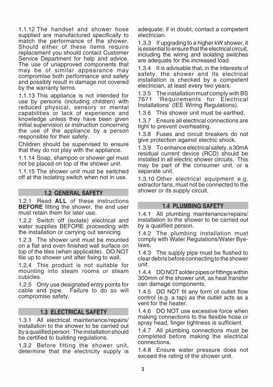
Fig. 5 Shower arrangement
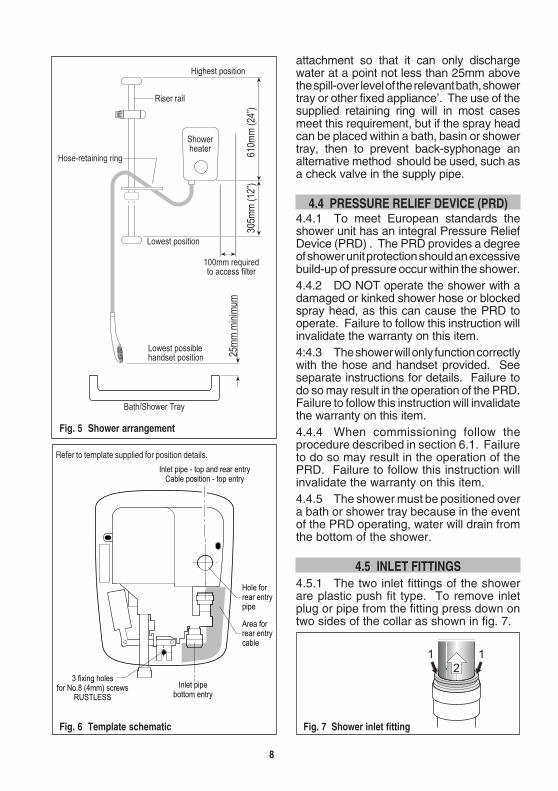
Fig. 6 Template schematic
Refer to template supplied for position details.
���
Fig. 7 Shower inlet fitting
attachment so that it can only dischargewater at a point not less than 25mm abovethe spill-over level of the relevant bath, showertray or other fixed appliance’. The use of thesupplied retaining ring will in most casesmeet this requirement, but if the spray headcan be placed within a bath, basin or showertray, then to prevent back-syphonage analternative method should be used, such asa check valve in the supply pipe.
4.4 PRESSURE RELIEF DEVICE (PRD)4.4.1 To meet European standards theshower unit has an integral Pressure ReliefDevice (PRD) . The PRD provides a degreeof shower unit protection should an excessivebuild-up of pressure occur within the shower.4.4.2 DO NOT operate the shower with adamaged or kinked shower hose or blockedspray head, as this can cause the PRD tooperate. Failure to follow this instruction willinvalidate the warranty on this item.4:4.3 The shower will only function correctlywith the hose and handset provided. Seeseparate instructions for details. Failure todo so may result in the operation of the PRD.Failure to follow this instruction will invalidatethe warranty on this item.4.4.4 When commissioning follow theprocedure described in section 6.1. Failureto do so may result in the operation of thePRD. Failure to follow this instruction willinvalidate the warranty on this item.4.4.5 The shower must be positioned overa bath or shower tray because in the eventof the PRD operating, water will drain fromthe bottom of the shower.
4.5 INLET FITTINGS4.5.1 The two inlet fittings of the showerare plastic push fit type. To remove inletplug or pipe from the fitting press down ontwo sides of the collar as shown in fig. 7.

9
5. FITTING THE SHOWER
5.1 PREPARATION5.1.1 Remove cover retaining screw andcarefully remove cover by pulling up the topedge. Avoid twisting, see fig. 8.Note: Bottom of the cover is hooked onto the shower unit.
5.1.2 Lift the connector from the back plateand separate connector by pressing on thelock lever, see fig. 8.5.1.3 Decide which entry points will bemost suitable for cable and water pipe , seepage 10.5.1.4 The mounting surface should bereasonably flat and smooth. Spacers(2.5mm) are provided for use when the wallsurface is uneven. The spacers should bepositioned on the fixing screws between thewall and the shower unit. The shower unitmust not be twisted or deflected in any way.Note: Four spacers are taped on the inside of the cover.
Fig. 8 Removing cover
stnioPyrtnEretaW
poT mottoB raeR
cirtcelEpoT ✔ ✔ ✕✕✕✕✕
mottoB ✔ ✔ ✔
raeR ✔ ✔ ✔
recommended
5.2 CABLE AND PIPE ENTRY OPTIONSTable C Entry points
5.2.1 Deviation from the designated entrypoints will invalidate product guarantee andmay make the shower unsafe.5.2.2 Fig. 10, page 10, shows pipe andcable entry options.
5.3 MOUNTING THE SHOWER5.3.1 The most convenient stage at whichto mount the shower on the wall will dependon the installation and the cable and pipeentry options selected. This will normally bewhen cable and pipe runs have beencompleted.5.3.2 To obtain accurate drilling positionsfor the 3 mounting holes either:-1. Use template supplied.2. Connect shower to water pipe and mark
the 3 holes.WARNING5.3.3 Before drilling any holes, checkposition of cables and water pipes withinthe walls.
5.3.4 Ensure shower is level, use a smallspirit level on top of the unit as shown in fig.9.
Fig. 9 Levelling shower
5.3.5 Screws and wall plugs are notsupplied. Suitable screws and plugs mustbe selected to suit the wall type. Therecommended screw size is no. 8 x 1½” (Ø4x 40mm).5.3.6 Remove shower from pipe, ifapplicable, then drill the wall and fit suitablewall plugs.

10
Fig. 10 Cable and pipe entry options
Cable REARPipe REAR
Cable REARPipe BOTTOM
Cable REARPipe TOP
Cable TOPPipe BOTTOM
Cable BOTTOMPipe TOP
Cable BOTTOMPipe REAR
Cable BOTTOMPipe BOTTOM
Cable TOPPipe TOP
Cable in trunking pipe on top
Cable in trunking pipe on top
Compression elbow outside coverStainless or chrome optional
Compression elbow outside coverStainless or chrome optional
Compression,solder ringor end feedelbow
Recommended

11
5.3.7 Connect shower to water pipe.5.3.8 Screw shower to wall. Do notovertighten screws. Use spacers (taped toinside of cover) to correct uneven walls.5.3.9 Check that the water inlet plug iscorrectly fitted and pushed fully home,into the inlet not being used - see fig. 8.5:3.10 Check that the solenoid lever is freeto move.
5.4 CABLE ENTRYFor cable entry options refer to page 10.5.4.1 For rear entry, the cable must emergefrom the wall only in the area specified, seefig. 5 and template.5.4.2 For rear entry at least 280mm ofcable is required protruding from the wall toallow connection to the terminal block, seefig. 11.
5.5.3 For concealed rear entry, solder ring,end feed or compression fittings are suitable.5.5.4 For concealed rear entry, great caremust be taken to accurately site the showerto suit the pipe position or accurately positionthe pipe to suit the shower position.5.5.5 Pipes for rear entry must be 18mmfrom the finished wall surface and be 70mmlong as shown in fig. 12.
%��� 1� ����
2�0������������(
%�������������0�
Fig. 11 Cable
�2
3�����
�2
3�
Fig. 12 Inlet pipe
5.4.3 When making cable runs, ensurethat the live (red) is on the left, this will easecable routing.5.4.4 Cables running up the wall for bottomentry or down the wall for top entry should beenclosed in suitable plastic trunking.5.4.5 Where both pipe and cable arearranged for top or bottom entry, the pipeshould be on top of the trunking as shown infig. 10.
5.5 PIPE ENTRYFor pipe entry options see page 10.5.5.1 An inlet plug should be removedfrom the chosen inlet port - see fig. 8.5.5.2 Concealed rear entry is consideredthe neatest option.
Solder ring and end feed Compression
5.5.6 Prior to fixing the shower unit, ensurethe pipe end is clean and slightly lubricated.Silicone based lubricants or petroleum jellyare suitable.5.5.7 Chromed pipes must have thechrome plating removed from the length ofpipe that enters the showers plastic inletconnector.
5.6 PLUMBING5.6.1 Decide where to connect to the watermain for the feed to the shower. Ensure thatthe pipe you have selected is not a gas pipe(they can look similar) or a hot water pipe.5.6.2 Cut the necessary pipework to length,assemble and offer up to the installationbefore making any soldered joints. Ensurethat the pipe is the correct length, since toshorten it can be difficult once the jointshave been made.5.6.3 Carry out any cutting with pipe cuttersin preference to a hacksaw, to minimiseswarf and burrs.5.6.4 Remember to incorporate a servicingvalve and if required, a check valve.

12
5.6.5 Locate the stop cock and turn off thewater supply. Check that the pipe youintend tapping into no longer carries waterby opening a tap that the pipe supplies.5.6.6 Make the connection to the pipe. If itis on a low-lying loop, there may be somewater left in the pipe, so be prepared forsome flow of water. Make all joints exceptthat to the shower before flushing.5.6.7 It is essentialto flush the systembefore the shower isconnected in order toclear any debris, bitsof solder and swarfwhich could enter anddamage componentswithin the shower, seefig. 13.
5.6.8 Check for leaks in all pipework andrectify as necessary.5.6.9 Do not use jointing compound onany pipe fittings for the shower installation.5.6.10 Carry out all soldering on the piperun to the shower before the shower is fitted.5.6.11 Remove outlet cap (if fitted) and fithandset hose, refer to separate fittinginstructions.
5.7 WIRING5.7.1 Remember, before working onelectrical components, ensure they arenot live. If in any doubt, switch off at themain switch at the fuse board or consumerunit.5.7.2 Design the system as outlined in 5.2.Lay the cable in the chosen route ensuringthat you have ample length and that the livefinishes on the left - refer to 5.4.3.5.7.3 Leave the connection to theconsumer unit or switch fuse until last.5.7.4 Strip the outer insulation back asshown in fig. 14. The protective coverindicates the position for 10mm cableinsulation and the minimum position for allcable sizes.
5.7.5 Cut the live, neutral and earth wiresto length and strip insulation from the liveand neutral wires leaving 15mm maximumbare wires. Add suitable green/yellowsleeving to earth cable leaving 10mmmaximum bare cable.
Fig. 15 Cover cut-out
Bottom entry shown
Fig. 13 Flushing pipework Fig. 14 Cable insulation length
5.7.6 ConnectionsRed or brown to live - LEFTBlack or blue to neutral - RIGHTGreen/yellow to earth - CENTREEnsure that all terminal block screws aretight, failure to do so will result in overheating.
5.8 PREPARING THE COVER5.8.1 When the cable and pipeconnections have been made and theshower screwed to the wall, the cover mayneed to be cut to suit cable/pipe entrypositions.5.8.2 The cover has thinned wall sectionsat the designated top and bottom cable andpipe entry positions, no cutting is requiredfor rear cable and rear pipe entry.5.8.3 Very carefully cut the cover only atthe designated positions using a juniorhacksaw or sidecutters. Alwaysfinish using around file. Checkthat the cover fitsover cables andpipes withoutinterference.

13
6. COMMISSIONINGCAUTIONFollow the commissioning procedureexactly as failing to do so could result indamage to the shower and may void theguarantee.
6.1 COMMISSIONING TESTSWARNING6.1.1 Items 6.1.2 to 6.1.9 are carried outwith the power OFF.
6.1.2 Once you have finished fitting theshower, carry out the following tests to ensurethat the shower is functioning as it should.6.1.3 Without fitting the shower head,secure the hose at low level where the watercan discharge safely. With the electricalpower turned OFF and the water supply tothe unit turned ON, push the solenoid pistonup until water runs through and out of theopen hose then after a few seconds release,see fig. 16. The handset may now be fitted.6.1.4 Secure the handset on the riser railwhere it can spray safely. With the powerturned OFF and water turned ON, push thesolenoid piston up until water sprays fromthe shower head, then after a few secondsrelease, see fig 16.6.1.5 Turn the flow control valve on theshower unit to it’s cold position i.e. with thelever at 6 o’clock. On the cover, turn theknob to the cold position. These two partsare keyed and must be correcly positionedin order for the cover to fit - see fig. 17.6.1.6 Hold the cover next to the showerand carefully connect the connector, then fitthe connector into its stow position at theside of the shower, neatly tucking the wiresin the recess provided, see fig 18.6.1.7 Refit the front cover by locating thelower front edge onto the shower unit thenpush the top back into position, ensurewires are not trapped.6.1.8 Secure the front cover by fitting theretaining screw into the badge recess. Donot overtighten. Do not fit the badge untilthe shower unit has been fully tested.6.1.9 Turn the knob and ensure it has
Fig. 16 Operating solenoid lever
5mm movement
Fig. 17 Valve and knob position
Blue Red
Flow control valveLever
smooth movement. If resistance is felt theknob may be fitted incorrectly. Commissionthe shower with the knob in the mid position.6.1.10 Turn on the electrical isolating switch.Press the stop/start button, the surroundshould illuminate.6.1.11 Slowly turn the flow control knob intothe red sector. The elements should now beheating and the temperature of the sprayshould increase.6.1.12 Adjust the flow control knob to givethe desired temperature. Allow a fewseconds after each adjustment for thetemperature to stabilise. A cool shower canbe obtained at the extreme end of the bluesector.6.1.13 The temperature obtained willdepend on the incoming water temperature.
Fig. 18 Connecting the connector
Tuck wires in recessPlug stow position
Lever @ 9 o’clock

14
Fig. 19 Inlet filter
8.3 CLEANING THE FILTEROnly to be carried out by competent person.8.3.1 To remove filter :-1. Turn shower electrical isolating switch
OFF.2. Turn water servicing valve OFF.3. Carefully remove badge using small
screwdriver and undo cover retainingscrew, pull cover away complete withknob, from the top and lift off - see fig. 8.
4. Unscrew the two screws at the side ofthe protective cover - see fig.19.
5. Withdraw filter element, inspect andclean.
6. Refit filter element and protective cover.The protective cover must be under thecable.
7. Refit cover - refer to 6.1.5 - 6.1.9.
7. OPERATOR INSTRUCTIONS
7.1 TO TURN ON & SET TEMPERATURE7.1.1 Turn on the electrical isolating switch.7.1.2 Press the stop/start button, thesurround should illuminate.7.1.3 Turn the flow control knob.7.1.4 Make adjustments carefully. Givethe shower a few seconds after eachadjustment to stabilise, then check thetemperature by hand before stepping intothe shower.
7.2 TO TURN OFF7.2.1 Press the stop/start button.7.2.2 Turn off the electrical isolating switch.NOTE7.2.3 For safety purposes, this shower hasa phased shut off. Water will continue to runfor a few seconds after switching off todissipate any residual heat from the heatexchanger.
8. MAINTENANCE
8.1 CLEANING THE HANDSET8.1.1 To maintain performance from theshower, the handset must be cleanedregularly, maybe as often as once a week inhard water areas. This is because fineholes can become restricted with scale andthis will affect the pattern of the spray andcause the shower to perform poorly.
8.2 INSPECTION8.2.1 We recommend that in the interestof safety, the shower and its electricalinstallation is checked by a qualifiedelectrician at least every two years.8.2.2 During inspection check that allelectrical connections are fully tightenedbefore replacing the cover, as looseconnections may cause overheating of theterminals and product failure.

15
SYMPTOM
1. No flow or notenough flow.
2. Flow adequatebut water toocold
3. Water too hot.
POSSIBLE CAUSE
A. Power failure, light does notilluminate.
B. Water control knob is turnedfully clockwise.
C. Water turned off at mains orservicing valve.
D. SHOWER UNIT SUSPECTEDOF BEING FROZEN.
E. There may be an outletblockage.
F. Blocked inlet filter.
G. Restricted operation ofsolenoid lever.
A. Water flow too high.
B. No power to unit.
C. Second stage thermal tripoperated.
A. Water flow too low.
REMEDY
A. Check power supply, consult electrician.
B. Turn flow control knob anticlockwise (3 o’clock).
C. Ensure water is fully turned on at the mains and at servicing valve in supply.
D. If so, DO NOT USE.(i) Switch off immediately at the electrical isolating switch.(ii) Turn water off at servicing valve (if fitted) or at stop cock.(iii) Contact our Customer Service Department.
E. Disconnect handset from hose and run the shower.(i) If water flows, then handset is blocked with scale or debris. Clean the
handset and spray rings/plate thoroughly.(ii) If the water does not flow, remove the hose from the shower outlet.
(a) If the water flows, the hose is blocked. This could be due todamage, severe kinking or even an obstruction. Hose must bereplaced with an approved hose.
(b) If the water does not flow, there is a blockage in the plumbing tothe shower, or the shower itself or the filter.
(c) Contact Customer Service Department if the shower is consideredto be the problem.
F. Remove filter for inspection - refer to 8.3.
G. Remove front cover and check operation of lever.
A. Reduce the flow by turning the flow control knob into the red section slowly.
B. Check isolator switched on.Check MCB or fuse at consumer unit.Check RCD (if fitted).Check 230/240V at shower terminal block. (Electrician only task)
C. This is a non-user serviceable part, shower must be replaced.
A. (i) Increase flow by turning control knob into blue sector.(ii) Ensure that the stop cock and servicing valve are fully open. If so, ask
the installer or the local water authority to check that the runningpressure is above the minimum required - see 4.1. This may beapparent during periods of high demand or when other outlets are used.
9. FAULT FINDING9.1.1 In the unlikely event of a problem,consult the troubleshooting chart.9.1.2 For the particular symptom followthe suggested remedies in the order given.9.1.3 IF YOU ARE UNABLE TO REMEDYTHE PROBLEM WITHOUT REMOVINGTHE COVER, YOU SHOULD CONTACTYOUR INSTALLER OR A QUALIFIEDELECTRICIAN.9.1.4 Where the fault cannot be correctedby either yourself or your installer, DO NOTREMOVE UNIT FROM THE WALL, but
contact Customer Service Department whowill try to help over the telephone. Ifnecessary, they can arrange a visit by aservice engineer. We find that the vastmajority of problems can be solved byreference to these fitting instructions or bydiscussion over the telephone. In the eventthat an engineer is called and the fault iscaused by faulty installation, usage, or lackof reasonable maintenance, a call-outcharge will be made.9.1.5 This shower is not suitable for use incommercial applications. Such use wouldinvalidate warranty.

16
Gainsborough ShowersSeafield House,Claylands Avenue,Worksop,Notts. S81 7BQ
SYMPTOM
4. Water runs fromaround hose.
5. Temperaturevariesdramaticallywhileshowering.
6. Poor spraypattern.
Also refer to handsetinstructions.
Product serial number
‘Place sticker here’
ServiceTel: 01959 560760Fax: 01959 560030www.gainsboroughshowers.co.ukemail:[email protected]
10. GUARANTEE AND SERVICE POLICYThis product is guaranteed against faulty materials andmanufacture for a period of one year from the date of purchaseprovided that:-
1. The unit has been installed in accordance with the Installationand User Instructions and all relevant Codes of Practice andRegulations in force at the time of Installation, and that allnecessary controls and safety valves have been fitted correctly.
2. The unit has not been modified or tampered with in anyway, and has been regularly maintained as detailed in theInstallation and User Instructions.
3. The unit has been used only for heating potable water.
4. The original proof of purchase is retained by the user inorder to validate the warranty.
The unit is not guaranteed against damage by frost, and theinner container with integral heating element is not guaranteedagainst excessive scale build-up.
This guarantee in no way affects the statutory rights of theconsumer.
The policy of Gainsborough is one of continuous productdevelopment and, as such, we reserve the right to changespecifications without notice.
3. Water too hotcont.
REMEDY
B. Clean the handset spray plate.
C. Check with installer or local water authority.
A. Turn off the electrical isolating switch and servicing valve - contactCustomer Service Department. Refer to 4.4.
B. Ensure washer is fitted and hose is correctly fitted and tight.
A. Check inlet requirements, see 4.1, page 5 and ensure no other mainwater devices are being used whilst showering.
B. Increase the flow by turning the flow control knob into the blue sector.Clean the handset and sprayplate.
C. Increase the flow by turning the flow control knob into the blue sector.Clean the handset and sprayplate.
A. Adjust spray plate to improve pattern.
B. Flow rate will naturally be lower when the inlet temperature is low, thisapplies to all electric showers.
C. Consult electrician.
POSSIBLE CAUSE
B. Spray plate blocked with scaleor debris.
C. Water pressure too low.
A. PRD has operated due toexcess pressure build-up.
B. Hose incorrectly fitted.
A. Water pressure to shower islow or unstable.
B. Thermal cut-out is operating,normally making a ‘click’ as itdoes so.
C. Scald protection device hasactivated.
A. Multi pattern handsetincorrectly set.
B. Low water inlet temp.
C. Low voltage
10.1 ENVIRONMENTAL INFORMATION10.1.1 The Waste Electrical and Electronic Equipment(Producer Responsibility) Regulation 2004
This product is outside the scope of the European WasteElectrical and Electronic Equipment Directive as interpretedwithin the UK. In the UK this product can therefore be disposedof through commercial non-WEEE waste facilities.
The original manufacturer does not accept any liabilityunder the WEEE directive.