enclosure 8, areva report anp-3434p, non-proprietary
TRANSCRIPT

L-MT-15-057 Enclosure 8
Enclosure 8
AREVA Report ANP-3434P
Non-Proprietary
AREVA Responses to RAI from SRXB and SNPB on MNGP EFW LAR
and
Computer Files on Compact Disc (CD)
Revision 1
August 2015
106 pages and 1 CD follow
CD labeled: AREVA Response to EFW LAR-SRXB/SNPB RAI-11

ANP-3434NP Revision 1
AREVA Responses to RAI from SRXB and SNPB on MNGP EFW LAR
August 2015
(c) 2015 AREVA Inc.
Controlled Document

AREVA Inc.
ANP-3434NP Revision 1
AREVA Responses to RAI from SRXB and SNPB on MNGP EFW LAR
Copyright © 2015
AREVA Inc. All Rights Reserved
Controlled Document

AREVA Responses to RAI from SRXB and SNPB on MNGP EFW LAR
ANP-3434NP Revision 1
Page i
Nature of Changes
Item Page Description and Justification
1. 2-1 Editorial change to last sentence in response.
2. 2-8 Deleted an extra word.
3. 2-12 Added a sentence about the STAIF and LAPUR codes.
4. 2-28 Revised the last sentence to state the articles have been placed on a CD.
5. 2-33 Corrected a misspelled name.
6. 2-48 Added a sentence.
7. 2-50, 2-51 Added proprietary brackets.
8. 2-56 Added RAI-8 and RAI-32 for AREVA mitigated ATWSi results. Added wording for clarity to footnote.
9. 2-65 Editorial change in first sentence of last paragraph.
10. A-2, B-2 Added a footnote about GE references.
AREVA Inc.
Controlled Document

AREVA Responses to RAI from SRXB and SNPB on MNGP EFW LAR
ANP-3434NP Revision 1
Page ii
Contents
1.0 Introduction .................................................................................................................. 1-1
2.0 RAIs and Responses ................................................................................................... 2-1 2.1 RAI-1: TIP Uncertainty Data ............................................................................. 2-1 2.2 RAI-2: TIP Uncertainty Update Process ............................................................ 2-8 2.3 RAI-3: EO-III Solution ....................................................................................... 2-9 2.4 RAI-4: Equipment Out of Service .................................................................... 2-10 2.5 RAI-5: SLMCPR/OLMCPR Penalties .............................................................. 2-11 2.6 RAI-6: STAIF Input Data ................................................................................. 2-12 2.7 RAI-7: KATHY Axial Conduction ..................................................................... 2-13 2.8 RAI-8: Mitigated ATWSI Calculations ............................................................. 2-17 2.9 RAI-9: Gamma-Densitometer Data – Void Fraction Uncertainty ..................... 2-18 2.10 RAI-10: Gamma-Scan Data – Power Distribution Uncertainty......................... 2-24 2.11 RAI-11:Maximum Heat Flux Under Steam Cooling ......................................... 2-27 2.12 RAI-12: MICROBURN-B2 Output Files ........................................................... 2-30 2.13 RAI-13:Clarification of RODEX2 and RODEX4 Methodology Use .................. 2-31 2.14 RAI-14: MELLLA+ Methods and TRACG Limitations and Conditions ............. 2-32 2.15 RAI-15: EO-III 5% HCOM Penalty .................................................................. 2-33 2.16 RAI-16: Axial Reactivity Variation During ATWSI ............................................ 2-34 2.17 RAI-17: Dryout Phenomena in AISHA ............................................................ 2-35 2.18 RAI-18: Time Dependent Gap Conductance ................................................... 2-36 2.19 RAI-19: Neutron Kinetics Theory .................................................................... 2-37 2.20 RAI-20: CPROM Model Development ............................................................. 2-38 2.21 RAI-21: Void History Bias ............................................................................... 2-41 2.22 RAI-22: Boundary Condition Transfer ............................................................. 2-42 2.23 RAI-23: Relative CPR Performance of ATRIUM-10XM and GE14 .................. 2-43 2.24 RAI-24: Pin Peaking Factor ............................................................................ 2-44 2.25 RAI-25: Anticipated Operational Occurrence (AOO) Event Results ................ 2-45 2.26 RAI-26: ATWS Long Term Evaluation ............................................................ 2-46 2.27 RAI-27: AREVA Codes and Methods .............................................................. 2-47 2.28 RAI-28 SLMCPR Calculation in the EFW Region ........................................... 2-50 2.29 RAI-29: Benchmarks Against Plant Transients ............................................... 2-52 2.30 RAI-30: Figures of Merit for Limiting Cases .................................................... 2-55 2.31 RAI-31: O-III Versus EO-III Setpoints ............................................................. 2-57 2.32 RAI-32: 2RPT ATWS ...................................................................................... 2-58 2.33 RAI-33: Reactivity Model ................................................................................ 2-59 2.34 RAI-34: ATWSI Analysis Assumptions ............................................................ 2-61 2.35 RAI-35: Gd Rod Treatment in Hot Rod Selection ............................................ 2-62 2.36 RAI-36: Heater Rods Versus Fuel Rods ......................................................... 2-64 2.37 RAI-37: SINANO Benchmarking Process: ...................................................... 2-66
Appendix A ...................................................................................................................... A-1
Appendix B ...................................................................................................................... B-1
Appendix C ...................................................................................................................... C-1
Appendix D ...................................................................................................................... D-1
Appendix E ...................................................................................................................... E-1 AREVA Inc.
Controlled Document

AREVA Responses to RAI from SRXB and SNPB on MNGP EFW LAR
ANP-3434NP Revision 1
Page iii
Nomenclature Acronym Definition
AOO Anticipated Operational Occurrences ASME American Society of Mechanical Engineers ATWS Anticipated Transient Without Scram ATWSi ATWS with instability BOC Beginning-of-Cycle BWR Boiling Water Reactor
CD Compact Disc CFR Code of Federal Regulations CHF Critical Heat Flux CPR Critical Power Ratio
DBA Design Basis Accident
ECCS Emergency Core Cooling Systems EFW Extended Flow Window EOC End-of-Cycle EPU Extended Power Uprate FWHOOS Feedwater Heaters Out of Service Gd Gadolinia GE General Electric GEH General Electric-Hitachi GL Generic Letter GNF Global Nuclear Fuels HCOM Hot Channel Oscillation Magnitude HPCI High Pressure Coolant Injection
LAR License Amendment Request LHGR Linear Heat Generation Rate LHGRFACp power-dependent Linear Heat Generation Rate LOCA Loss-Of-Coolant Accident MCPR Minimum Critical Power Ratio MELLLA Maximum Extended Load Line Limit Analysis MELLLA+ Maximum Extended Load Line Limit Analysis Plus MNGP Monticello Nuclear Generating Plant
NRC Nuclear Regulatory Commission, U.S.
OLMCPR Operating Limit MCPR OLTP Original Licensed Thermal Power
AREVA Inc.
Controlled Document

AREVA Responses to RAI from SRXB and SNPB on MNGP EFW LAR
ANP-3434NP Revision 1
Page iv
Nomenclature (continued) Acronym Definition
PCT Peak Clad Temperature PLFR Part-Length Fuel Rods
RAI Request for Additional Information RPT Recirculation Pump Trip
SLMCPR Safety Limit MCPR SLO Single-Loop Operation SNPB Staff in Nuclear Performance and Code Review Branch SRXB Staff in Reactor Systems Branch SRV Safety Relief Valve STD Standard Deviation TIP Traversing In-core Probe TLO Two-Loop Operation
AREVA Inc.
Controlled Document

AREVA Responses to RAI from SRXB and SNPB on MNGP EFW LAR
ANP-3434NP Revision 1
Page 1-1
1.0 Introduction
In Reference 1, Northern States Power Company - a Minnesota corporation, doing business as Xcel Energy, submitted a license amendment request for the Monticello Nuclear Generating Plant (MNGP). The application was supplemented by Reference 2. The amendment would revise the Technical Specifications and approve certain AREVA analytical methods to support plant operation in the expanded power-flow domain described as the Extended Flow Window (EFW). EFW is the same operating domain expansion as Maximum Extended Load Line Limit Analysis Plus (MELLLA+). The U.S. Nuclear Regulatory Commission (NRC) staff in the Reactor Systems Branch (SRXB) and Nuclear Performance and Code Review Branch (SNPB) has reviewed the application and concluded that additional information is necessary to complete its review. Requests for Additional Information (RAI) were provided as an attachment to Reference 3. The RAI and the AREVA responses are attached. These responses are provided so Xcel Energy can provide a complete set of responses to the NRC by combining the AREVA responses with the responses being prepared by Xcel Energy. In some cases the responses to RAI refer to AREVA documents that were transmitted to the NRC in support of the MNGP transition to AREVA fuel (Reference 4). This fuel transition License Amendment Request (LAR) has been approved by the NRC (Reference 5). References
1. License Amendment Request for AREVA Extended Flow Window, October 3, 2014, MNGP L-MT-14-044. (ADAMS Accession No. ML 14283A119)
2. License Amendment Request for AREVA Extended Flow Window Supplement to Response to NRC Staff Questions (TAC No. MF5002), January 9, 2015, MNGP L-MT-14-103. (ADAMS Accession No. ML15022A165 and ML 15022A167)
3. Monticello Nuclear Generating Plant –Request for Additional Information (SRXB/SNPB) re: AREVA Extended Flow Window License Amendment Request (TAC No MF5002) – email from Terry Beltz (NRC) to Glenn Adams (Xcel Energy), August 5th, 2015.
4. License Amendment Request for Transition to AREVA ATRIUM 10XM Fuel and AREVA Safety Analysis Methodology, July 15, 2013, MNGP L-MT-13-055. (ADAMS Accession No. ML13200A187)
5. Letter from T. A. Beltz (NRC) to P. A. Gardner (Xcel Energy), “Monticello Nuclear Generating Plant – Issuance of Amendment to Transition to AREVA ATRIUM 10XM Fuel and AREVA Safety Analysis Methods (TAC NO. MF2479), June 5, 2015 (ADAMS Accession No. ML 15072A141).
AREVA Inc.
Controlled Document

AREVA Responses to RAI from SRXB and SNPB on MNGP EFW LAR
ANP-3434NP Revision 1
Page 2-1
2.0 RAIs and Responses
2.1 RAI-1: TIP Uncertainty Data Please provide Traversing Incore Probe (TIP) uncertainty data plots for high power-density plants with AREVA fuel (e.g. Kuosheng, Gunndremingen, Brunswick and Susquehanna) for a minimum of 3 cycles. For each plant provided, identify the pre- and post-Extended Power Uprate (EPU) cycles.
AREVA Response AREVA has performed a series of benchmark analyses for more modern cycle operation than was presented in the topical report EMF-2158 (Reference 1-1). The plant parameters for these plants are described in Table 1-1. The 2-D radial and 3-D nodal relative standard deviations (STDs) between the predicted traversing in-core probe (TIP) distributions and the measured TIP distributions are presented in Figure 1-1 and Figure 1-2 for BWR-B, respectively. BWR-B was uprated to 120% of original licensed thermal power (OLTP) in cycle 15. Similar curves are presented for BWR-E in Figure 1-3 and Figure 1-4. This is a high power density plant that has operated at higher power density and stronger spectral shift than is expected for Monticello operation. KWU-S is another high power density plant that has operated with strong spectral shift. The 2-D and 3-D relative STD’s for this plant are presented in Figure 1-5 and Figure 1-6. BWR-H and BWR-I have been operating at 120% of OLTP for all of the cycle presented. Their TIP statistical plots are presented in Figure 1-7 through Figure 1-10.
These results indicate that there is not a significant difference in the TIP statistics for pre- and post-Extended Power Uprate (EPU) operation.
References for RAI-1
1-1. EMF-2158(P)(A) Revision 0, Siemens Power Corporation Methodology for Boiling Water Reactors:
Evaluation and Validation of CASMO-4/MICROBURN-B2, Siemens Power Corporation, October 1999.
AREVA Inc.
Controlled Document

AREVA Responses to RAI from SRXB and SNPB on MNGP EFW LAR
ANP-3434NP Revision 1
Page 2-2
Table 1-1. Commercial BWRs Selected for Benchmark Analysis
Reactor Rated Power (MWth)
Rated Flow
(Mlb/hr)
Core Size
Lattice Type
Benchmark Cycles
Fuel Types
Operation Mode
BWR-B 3441/3952 100.0 764 C 1-15 8x8-2 9x9-2
10x10-9
Base Load Power Uprate
BWR-E 2894 84.5 624 S 1-21 8x8-2 9x9-2 9x9-5
10x10-9
Base Load Spectral Shift
KWU-S 3840 113.5 784 C 9-16 9X9-1 10X10-9 9X9-1 MOX
Base Load Coast Down
BWR-H 2923 77.0 560 D 14-18 10x10-9 Base Load Coast Down
BWR-I 2923 77.0 560 D 17-20 10x10-9 Base Load
AREVA Inc.
Controlled Document

AREVA Responses to RAI from SRXB and SNPB on MNGP EFW LAR
ANP-3434NP Revision 1
Page 2-3
Figure 1-1. BWR-B Standard Deviations of 2-D (Radial) TIP Relative Differences
Figure 1-2. BWR-B Standard Deviations of 3-D TIP Relative Differences
AREVA Inc.
Controlled Document
AREVA Responses to RAI from SRXB and SNPB on MNGP EFW LAR
ANP-3434NP Revision 1
Page 2-4
Figure 1-3. BWR-E Standard Deviations of 2-D (Radial) TIP Relative Differences
Figure 1-4. BWR-E Standard Deviations of 3-D TIP Relative Differences
AREVA Inc.
Controlled Document

AREVA Responses to RAI from SRXB and SNPB on MNGP EFW LAR
ANP-3434NP Revision 1
Page 2-5
Figure 1-5. KWU-S Standard Deviations of 2-D (Radial) TIP Relative Differences
Figure 1-6. KWU-S Standard Deviations of 3-D TIP Relative Differences
AREVA Inc.
Controlled Document

AREVA Responses to RAI from SRXB and SNPB on MNGP EFW LAR
ANP-3434NP Revision 1
Page 2-6
Figure 1-7. BWR-H Standard Deviations of 2-D (Radial) TIP Relative Differences
Figure 1-8. BWR-H Standard Deviations of 3-D TIP Relative Differences
AREVA Inc.
Controlled Document

AREVA Responses to RAI from SRXB and SNPB on MNGP EFW LAR
ANP-3434NP Revision 1
Page 2-7
Figure 1-9. BWR-I Standard Deviations of 2-D (Radial) TIP Relative Differences
Figure 1-10. BWR-I Standard Deviations of 3-D TIP Relative Differences
AREVA Inc.
Controlled Document

AREVA Responses to RAI from SRXB and SNPB on MNGP EFW LAR
ANP-3434NP Revision 1
Page 2-8
2.2 RAI-2: TIP Uncertainty Update Process Monticello is expected to collect TIP data in the EFW domain.
a) Provide a short description of the TIP calibration process and how it is reflected in the Safety Limit Minimum Critical Power Ratio (SLMCPR) uncertainty calculations.
b) Provide a description of the process that would be used to reflect the higher uncertainty in the SLMCPR analyses if higher uncertainties are measured during EFW operation.
AREVA Response
Xcel Energy to provide response
AREVA Inc.
Controlled Document

AREVA Responses to RAI from SRXB and SNPB on MNGP EFW LAR
ANP-3434NP Revision 1
Page 2-9
2.3 RAI-3: EO-III Solution a) Provide a roadmap and explanation of how the Extended Flow Window Stability (EFWS) trip is
defined and implemented in technical specifications and COLR.
b) Define the methodology/process to calculate the EFWS trip on cycle specific basis.
c) Provide a justification for the removal of manual Backup Stability Protection (BSP) from section 5.6.3 of Technical Specifications.
AREVA Response
Xcel Energy to provide response
AREVA Inc.
Controlled Document

AREVA Responses to RAI from SRXB and SNPB on MNGP EFW LAR
ANP-3434NP Revision 1 Page 2-10
2.4 RAI-4: Equipment Out of Service The Monticello LAR states that Feedwater Heaters Out of Service (FWHOOS) is not allowed; however, all the LAR calculations have been performed with a +5F -10F FW temperature band.
Clarify how the FWHOOS requirement implementation in the plant will be implemented.
AREVA Response
AREVA analyzed and licensed a band of -10/+5F around nominal feedwater temperature. Due to hardware limitations the operation with Feedwater Heaters Out of Service (FWHOOS) is not possible at Monticello.
AREVA Inc.
Controlled Document

AREVA Responses to RAI from SRXB and SNPB on MNGP EFW LAR
ANP-3434NP Revision 1 Page 2-11
2.5 RAI-5: SLMCPR/OLMCPR Penalties Provide a tabular summary of the OLMCPR and SLMCPR penalties, if any, proposed for Monticello with AREVA methods. Provide a comparison between the current (GEH) penalties and proposed (AREVA) penalties, if any.
AREVA Response
There are no proposed penalties for Monticello operating limit minimum critical power ratio (OLMCPR) or safety limit minimum critical power ratio (SLMCPR) with AREVA methods.
AREVA Inc.
Controlled Document
AREVA Responses to RAI from SRXB and SNPB on MNGP EFW LAR
ANP-3434NP Revision 1 Page 2-12
2.6 RAI-6: STAIF Input Data Provide data from sample STAIF calculations in sufficient detail to perform LAPUR confirmatory calculations.
AREVA Response
STAIF and LAPUR are frequency-domain codes for calculating the linear stability of BWRs. The requested data have been placed on a compact disk (CD) labeled “AREVA Response to EFW LAR-SRXB/SNPB RAI-6”.
Information about the provided data files is listed below: MICROBURN Files: 88004 Jan 8 2013 14:32:42 hyd.MON28_10_44.5f72.5p_16175e 5864500 Jan 8 2013 14:32:42 ram.MON28_10_44.5f72.5p_16175e 1736 Jan 8 2013 14:32:42 rdx.MON28_10_44.5f72.5p_16175e 2602296 Jan 8 2013 14:32:42 stf.MON28_10_44.5f72.5p_16175e STAIF Input File: 3650 Feb 4 2013 08:09:34 staif_inp.MON28_44.5f72.5p 4949 Jan 18 2013 12:10:18 staif.recirc STAIF Output File: 5286 Feb 8 2013 08:58:10 results.MON28_10_44.5f72.5p_16175e
1212783 Feb 8 2013 08:58:11 staif.MON28_10_44.5f72.5p_16175e
AREVA Inc.
Controlled Document

AREVA Responses to RAI from SRXB and SNPB on MNGP EFW LAR
ANP-3434NP Revision 1 Page 2-13
2.7 RAI-7: KATHY Axial Conduction Provide a discussion and sample calculation of the possible error incurred in the KATHY facility test measurements by discarding axial conduction to a possibly-nearby quench front.
AREVA Response
[
]
AREVA Inc.
Controlled Document

AREVA Responses to RAI from SRXB and SNPB on MNGP EFW LAR
ANP-3434NP Revision 1 Page 2-14
[
]
AREVA Inc.
Controlled Document

AREVA Responses to RAI from SRXB and SNPB on MNGP EFW LAR
ANP-3434NP Revision 1 Page 2-15
[
]
A conservative, yet simpler, way of analyzing the axial conduction error without requiring the solution of a differential equation is given below. The axial heat conduction is obtained assuming a linear temperature profile between the two points of interest, the high value at the thermocouple location and the wet spot, from:
( ) high sataxial
T TTQ kA k Dz L
π ε ε−D
= = −D
Where:
k Heater pin thermal conductivity
A Heat transfer area (heater pin cross section area)
D Outer diameter of the heater pin
ε Wall thickness of the heater pin
highT Temperature measured by thermocouple
satT Saturation temperature approximating the pin temperature under wetted condition
L Distance between thermocouple and wetted elevation downstream of the spacer
The heat transferred by convection at the outer pin surface in the radial direction for the same pin length is obtained from
( )radial dry high satQ D L h T T= −π
AREVA Inc.
Controlled Document

AREVA Responses to RAI from SRXB and SNPB on MNGP EFW LAR
ANP-3434NP Revision 1 Page 2-16
where:
dryh Heat transfer coefficient under dryout conditions
The ratio of axial-to-radial heat transfer is obtained from
( )
2axial
radial dry
k DQRQ h D L
−= =
ε ε
which is independent of the temperature measurement.
[
]
It is therefore concluded that the error due to neglecting axial heat conduction [ ], which is insignificant.
AREVA Inc.
Controlled Document

AREVA Responses to RAI from SRXB and SNPB on MNGP EFW LAR
ANP-3434NP Revision 1 Page 2-17
2.8 RAI-8: Mitigated ATWSI Calculations ATWSI calculations in the Monticello LAR are for unmitigated (i.e., no operator actions) assumptions.
a) Provide realistic Anticipated Transient Without Scram with Instability (ATWSI) calculations under the expected conditions crediting operator actions. Provide sensitivity results for later operator action time.
b) Provide a discussion of uncertainty treatment (e.g., hGap, inlet friction).
c) Describe the methodology used by AISHA to excite the oscillation when the decay ratio (DR) is close to 1.0.
AREVA Response
To be provided at a later date in a different AREVA report (ANP-3435).
AREVA Inc.
Controlled Document

AREVA Responses to RAI from SRXB and SNPB on MNGP EFW LAR
ANP-3434NP Revision 1 Page 2-18
2.9 RAI-9: Gamma-Densitometer Data – Void Fraction Uncertainty Currently, Monticello has a 0.01 Operating Limit Minimum Critical Power Ratio (OLMCPR) penalty because of void uncertainty.
Provide a technical justification for an appropriate void uncertainty penalty for AREVA methods. Include available gamma densitometer data from Karlstein Thermal Hydraulic facility (KATHY) for steady state void methods benchmark.
AREVA Response
The 0.01 Operating Limit Minimum Critical Power Ratio (OLMCPR) penalty was imposed by the Nuclear Regulatory Commission (NRC) in the review of the Licensing Topical Report for application of General Electric (GE) methods to expanded operating domains (Reference 9-1). In particular, the NRC examined the qualification database with respect to the intended application. This included both the potentially higher range of nodal void fractions resulting from Extended Power Uprate (EPU) operating conditions in concert with an Expanded Flow Window (EFW) and modern fuel design attributes.
The NRC stated that although the supporting data did not cover all of the current operational conditions (e.g., the current radial and axial lattice peaking, the 10x10 bundle design features, such as the part-length fuel rods (PLFRs) and new spacer design), that, overall, the correlation did not exhibit unexpected behavior and remains relatively predictable. However, the NRC staff expected that most likely the uncertainty levels are higher than those reported. Due to the lack of experimental data that proved otherwise an interim penalty on the OLMCPR was appropriate (Reference 9-1, SER p. 119): Void-Quality Correlation Limitation 1
“For applications involving PANCEA/ODYN/ISCOR/TASC for operation at EPU and MELLLA+, an additional 0.01 will be added to the OLMCPR, until such time that GE expands the experimental database supporting the Findlay-Dix void-quality correlation to demonstrate the accuracy and performance of the void-quality correlation based on experimental data representative of the current fuel designs and operating conditions during steady-state, transient, and accident conditions”.
Similar to GE methods, the AREVA steady-state core simulator that provides the state point specific core characterization and the plant transient simulator utilize drift flux correlations to predict the local and core wide void behavior that ultimately contributes to the transient changes in reactivity and power. The 0.01 OLMCPR penalty for the GE methods is focused on whether the drift flux correlation adequately predicts the impact of modern fuel design characteristics such as PLFRs and swirl vane spacer designs on the local void fraction and whether the correlation correctly predicts higher void fractions that may be associated with EPU and EFW conditions but were not included in the qualification database. Concurrent with the AREVA fuel design development that led to the introduction of PLFRs and swirl vane spacer designs, fundamental testing was conducted to assess the adequacy of current methodologies in predicting steady-state behavior (critical power, pressure drop and void fraction) as well as dynamic behavior (channel decay ratio and instabilities).
AREVA Inc.
Controlled Document

AREVA Responses to RAI from SRXB and SNPB on MNGP EFW LAR
ANP-3434NP Revision 1 Page 2-19
The first concern associated with the OLMCPR penalty was the applicability of the void-quality correlation to modern fuel designs. AREVA performed void fraction measurements to specifically assess the impact of the ATRIUM-10 fuel design attributes. These were performed at the KATHY test facility using a prototypical BWR test assembly. The test assembly used 8 PLFRs, mixing vane grids, a [
] typical of critical heat flux (CHF) tests. The tests were conducted using a scanning gamma densitometer that traversed across the test section. Void measurements were made at one of three different elevations in the assembly for each test point: just below the end of the part length fuel rods, midway between the uppermost two spacers, and just below the uppermost spacer. The second concern associated with the OLMCPR penalty was the applicability of the void-quality correlation to the full range of operating conditions typical of EPU operation including EPU operation with an Extended Flow Window. To assess the high void fraction performance, AREVA performed gamma tomography measurements on the ATRIUM 10XM (the fuel design to be used in Monticello). Again, the tests were performed at the KATHY test facility using a prototypical BWR CHF test assembly. The test assembly used the PLFR and grid spacer configuration of the ATRIUM 10XM and a [
], but unlike the ATRIUM-10 tests this assembly had a [
] in the test facility. For reference purposes, AREVA has used the FRIGG-2 (Reference 9-2) and FRIGG-3 (Reference 9-3) void fraction measurements to qualify the void-quality correlations used in the steady-state core simulator and the transient methods. The full range of the validation database, including the ATRIUM-10 and ATRIUM 10XM measurements at KATHY, are presented in Table 9-1. Plots presenting the comparisons between the void-quality correlations and measured data are presented in Figure 9-1 and Figure 9-2 respectively for the steady-state core simulator and transient methods. Visual examinations of these plots as well as comparisons of the means and standard deviations in Table 9-2 demonstrate that the modern AREVA fuel design attributes and the potential operation at high void fractions for EPU and EPU with Extended Flow Windows result in no significant change in the void-quality application uncertainties relative to the historic validation. Therefore, there should be no penalty for higher uncertainties in the void-quality correlation for EPU and EPU with Extended Flow Window for the advanced AREVA fuel designs at Monticello. References for RAI-9 9-1 NEDO-33173-A Revision 1, “Applicability of GE Methods to Expanded Operating Domains," dated
September 2010. (ADAMS Accession No. ML 102920137) 9-2 O. Nylund et al., “Hydrodynamic And Heat Transfer Measurements On A Full-Scale Simulated 36-
Rod Marviken Fuel Element With Uniform Heat Flux Distribution,” FRIGG-2, R-447/RTL-1007, May 1968.
9-3 O. Nylund et al., “Hydrodynamic and Heat Transfer Measurements on A Full-Scale Simulated 36-Rod Marviken Fuel Element with Non-Uniform Radial Heat Flux Distribution,” FRIGG-3, R-494/RL-1154, November 1969.
AREVA Inc.
Controlled Document

AREVA Responses to RAI from SRXB and SNPB on MNGP EFW LAR
ANP-3434NP Revision 1 Page 2-20
Table 9-1. Summary of AREVA Void Fraction Database FRIGG-2
(Reference 9-2)
FRIGG-3 (Reference 9-3)
ATRIUM-10
(KATHY) ATRIUM 10XM
(KATHY)
Axial Power Shape uniform uniform [
] [
]
Radial Power Peaking uniform peaking [ ] [ ]
Bundle Design
circular array with 36 rods + central thimble
circular array with 36 rods + central thimble
prototypic
ATRIUM-10
bundle
prototypic
ATRIUM-10XM bundle
Pressure (psi) 725 725,1000,1260 [ ] [ ]
Mass Flow Rate (lbm/s) 14.3 to 31.0* 10.1 to 42.5* [ ] [ ]
Equilibrium Quality
(fraction) -0.036 to 0.203 -0.058 to 0.330 [ ] [ ]
Maximum Void (fraction)
0.828 0.848 [ ] [ ]
Measurement
Uncertainty (fraction)
0.025 0.016 [ ] [ ]
Number of Data
27 tests, 174 points
39 tests, 157 points [ ] [ ]
* (Calculated from mass flux assuming ATRIUM-10 inlet flow area)
AREVA Inc.
Controlled Document

AREVA Responses to RAI from SRXB and SNPB on MNGP EFW LAR
ANP-3434NP Revision 1 Page 2-21
Table 9-2. Summary of Void-Quality Correlation Statistics
FRIGG ATRIUM-10
(KATHY) ATRIUM 10XM
(KATHY) Core Simulator Mean [ ] [ ] [ ] Core Simulator Standard Deviation [ ] [ ] [ ]
Transient Method Mean [ ] [ ] [ ]
Transient Method Standard Deviation [ ] [ ] [ ]
AREVA Inc.
Controlled Document

AREVA Responses to RAI from SRXB and SNPB on MNGP EFW LAR
ANP-3434NP Revision 1 Page 2-22
Figure 9-1. Predicted vs. Measured Void Fraction for AREVA
Steady-State Core Simulator
AREVA Inc.
Controlled Document

AREVA Responses to RAI from SRXB and SNPB on MNGP EFW LAR
ANP-3434NP Revision 1 Page 2-23
Figure 9-2. Predicted vs. Measured Void Fraction for AREVA Transient Methods
AREVA Inc.
Controlled Document

AREVA Responses to RAI from SRXB and SNPB on MNGP EFW LAR
ANP-3434NP Revision 1 Page 2-24
2.10 RAI-10: Gamma-Scan Data – Power Distribution Uncertainty Currently, Monticello has a 0.03 SLMCPR penalty for power densities greater than 42MWt/Mlbm/hr.
Provide a technical justification for an appropriate power distribution uncertainty penalty supported by available data using AREVA methods. Include the available gamma scan data in the response.
AREVA Response Figures A-18 and A-24 of the AREVA report ANP-3224 (Reference 10-1) present the traversing in-core probe (TIP) statistics information taken from the CASMO-4/MICROBURN-B2 topical report, EMF-2158 (Reference 10-2) as a function of core Power/Flow ratio. These plots show TIP comparison data up to Power/Flow ratios up to [ ]. There is no indication of higher uncertainties for higher Power/Flow ratios. This approach was repeated for a more current collection of benchmark data and is presented in Figure 10-1. Again there is no indication of higher uncertainties for high Power/Flow ratios. [ ]
Gamma Scan data for modern fuel designs was presented in the CASMO-4/MICROBURN-B2 topical report, EMF-2158 (Reference 10-2), Section 8. Since the release of that document an additional campaign was performed where 48 assemblies including AREVA ATRIUM-10B and Westinghouse SVEA-96 Optima2 designs were scanned. In addition, rod measurements were carried out on two assemblies. The results of an analysis performed by AREVA for this campaign are summarized in Table 10-1 and Table 10-2. The unique characteristic of this campaign is that the operation prior to reactor shutdown for these scans included several inserted control blades. One of the assemblies, chosen for individual rod scans, was operated with the control blade inserted 20%. Significant deviations were observed for rods near the control blade. These are not of a safety concern as the powers in these rods are suppressed.
References for RAI-10
10-1. ANP-3224P Revision 2, Applicability of AREVA NP BWR Methods to Monticello, AREVA NP, June 2013. (transmitted to NRC as part of the fuel transition LAR)
10-2. EMF-2158(P)(A) Revision 0, Siemens Power Corporation Methodology for Boiling Water Reactors: Evaluation and Validation of CASMO-4/MICROBURN-B2, Siemens Power Corporation, October 1999
AREVA Inc.
Controlled Document

AREVA Responses to RAI from SRXB and SNPB on MNGP EFW LAR
ANP-3434NP Revision 1 Page 2-25
Table 10-1. Recent Gamma Scan Bundle Statistical Results
Table 10-2. Recent Gamma Scan Rod Statistical Results
AREVA Inc.
Controlled Document

AREVA Responses to RAI from SRXB and SNPB on MNGP EFW LAR
ANP-3434NP Revision 1 Page 2-26
Figure 10-1. 3-D TIP Statistics vs. Core Power/Flow Ratio
AREVA Inc.
Controlled Document

AREVA Responses to RAI from SRXB and SNPB on MNGP EFW LAR
ANP-3434NP Revision 1 Page 2-27
2.11 RAI-11:Maximum Heat Flux Under Steam Cooling AREVA has measured the steam heat transfer coefficient (HTC) using data from the KATHY oscillatory tests.
a) Using this HTC, provide the maximum heat flux without reaching peak cladding temperature (PCT) limits in absolute units and also in terms of percent the core-average heat flux and the limiting linear heat generation rate (LHGR).
b) Provide additional experimental data supporting the HTC value measured by AREVA.
c) Provide a justification for extrapolation of the heat transfer coefficient to higher pressures than those tested.
AREVA Response a) Using this HTC, provide the maximum heat flux without reaching peak cladding temperature
(PCT) limits in absolute units and also in terms of percent the core-average heat flux and the limiting linear heat generation rate (LHGR).
[
]
The peak clad temperature limit is
max 1204oT C=
The sink temperature is taken as the saturation temperature, o297 CsatT = at the pressure of 82 bar.
The maximum heat flux corresponding to these conditions is obtained as
[ ]
The corresponding maximum linear heat generation rate is calculated for a fuel rod with outer diameter, [ ] Thus,
[ ]
The core average heat flux and linear heat generation rate are obtained for the rated power of 2004 MW and 484 bundles. For ATRIUM 10XM fuel bundle, the heat transfer area is
[ ]
and the total active length of the rods is
AREVA Inc.
Controlled Document
AREVA Responses to RAI from SRXB and SNPB on MNGP EFW LAR
ANP-3434NP Revision 1 Page 2-28
[ ]
Thus, the average heat flux at rated power is obtained as
[ ]
The average linear heat generation rate at rated power is obtained as
[ ]
Notice that the average heat flux and linear heat generation rate would be calculated at lower values than provided above if the basis were to be the natural circulation power level instead of the rated power.
Based on these values, the maximum heat flux and linear heat generation rate correspond to approximately [ ] of the core average values at rated power.
b) Provide additional experimental data supporting the HTC value measured by AREVA.
The data produced at JAERI provide confirmation of the HTC measured by AREVA. The data are published in the article, Tadashi Igutchi, “Status of Transient Thermal-Hydraulic Demonstration test Program at JAERI” (Reference 11-1).
The HTC data are plotted as function of wall superheat and for the pressures of 4, 10, and 15.5 MPa [
] The trend as stated in the article is that “… higher pressure and lower superheat give
higher heat transfer coefficient.”
Recent experimental data can be found in Yasuteru SIBAMOTO et al., “Core Heat Transfer Coefficients Immediately Downstream of the Rewetting Front during Anticipated Operational Occurrences for BWRs” (Reference 11-2). The data include measurements at pressures of 2, 4, and 7 MPa. [
]
A copy of the two articles referenced above has been placed on a CD labeled “AREVA Response to EFW LAR-SRXB/SNPB RAI-11”.
AREVA Inc.
Controlled Document

AREVA Responses to RAI from SRXB and SNPB on MNGP EFW LAR
ANP-3434NP Revision 1 Page 2-29
c) Provide a justification for extrapolation of the heat transfer coefficient to higher pressures than those tested.
[
]
References for RAI-11
11-1. Tadashi Igutchi et al. “Status of Transient Thermal-Hydraulic Demonstration Test Program at JAERI,” The 5th International Conference on Nuclear Engineering, ICONE5, Paper 2347, Nice-France May 26-30, 1997.
11-2. Yasuteru SIBAMOTO et al., “Core Heat Transfer Coefficients Immediately Downstream of the Rewetting Front during Anticipated Operational Occurrences for BWRs,” Journal of NUCLEAR SCIENCE and TECHNOLOGY, Vol. 48, No. 3, p. 440-453, 2011.
AREVA Inc.
Controlled Document

AREVA Responses to RAI from SRXB and SNPB on MNGP EFW LAR
ANP-3434NP Revision 1 Page 2-30
2.12 RAI-12: MICROBURN-B2 Output Files a) Provide the MICROBURN-B2 output file for the Monticello equilibrium cycle step-through with
detailed edits of power and void fraction.
b) Provide the MICROBURN-B2 output file for an operating cycle of a high power density plant with detailed edits of power, void fraction and calculated TIP responses. Also, provide the corresponding measured TIP’s.
AREVA Response The requested data have been placed on a CD labeled “AREVA Response to EFW LAR-SRXB/SNPB RAI-12”.
Information about the provided data files is listed below: 115160157 ------ Oct 31 2012 13:48:02 mcb.monti_eq_GT63c 212136849 ------ Jun 10 2015 17:19:00 mcb.ks2c23_cf_spu_exv 35532 ------ Jun 10 2015 17:17:59 tip.ks2c23_cf_spu_exv 16907 ------ Dec 20 2013 15:37:37 TP6-13APR30-100604.LIS 16907 ------ Sep 01 2013 17:50:35 TP6-13AUG27-103040.LIS 16907 ------ Jan 07 2014 21:37:33 TP6-13DEC24-100724.LIS 16907 ------ Dec 20 2013 15:37:37 TP6-13JUN06-102500.LIS 16907 ------ Dec 20 2013 15:37:37 TP6-13MAR21-102249.LIS 16907 ------ Nov 17 2013 19:46:44 TP6-13NOV14-100626.LIS 16907 ------ Oct 14 2013 17:23:29 TP6-13OCT08-100934.LIS 16907 ------ Apr 20 2014 18:04:47 TP6-14APR15-100123.LIS 16907 ------ Aug 11 2014 23:07:37 TP6-14AUG07-101805.LIS 16907 ------ Jul 02 2014 18:34:00 TP6-14JUL01-095925.LIS 16907 ------ Mar 09 2014 19:39:17 TP6-14MAR06-100124.LIS 16907 ------ May 25 2014 20:33:49 TP6-14MAY22-101740.LIS 16907 ------ Sep 21 2014 18:13:21 TP6-14SEP16-102517.LIS
AREVA Inc.
Controlled Document

AREVA Responses to RAI from SRXB and SNPB on MNGP EFW LAR
ANP-3434NP Revision 1 Page 2-31
2.13 RAI-13:Clarification of RODEX2 and RODEX4 Methodology Use Clarify the COLR analysis methodology given that the RODEX2 and RODEX4 methods are referenced. Specifically, clarify which code will used for each transient in the COLR.
AREVA Response The AREVA report ANP-3295, Table 2.3 (Reference 13-1) provides a summary of the AREVA codes and their application. The methodology applicability report ANP-3224 (Reference 13-2) provides further details about the application of RODEX2 and RODEX4 code in Monticello analyses. A summary of the usage of the two fuel codes is provided in the following. RODEX4 is used in the thermal-mechanical licensing and safety calculations in order to demonstrate compliance with NUREG-0800, SRP 4.2 criteria for normal operation and AOOs. This includes the transient LHGR analyses that assure compliance with the AOO 1% strain increment and centerline melting safety criteria. The details of the RODEX4 methodology are described in Reference 13-3. RODEX2 is the legacy thermal-mechanical licensing and safety analysis code that is still used as part of the NRC approved AREVA methodologies for AOO and LOCA.
The thermal-mechanical criteria for AOO fast transients are analyzed with RODEX4 using the transient power response calculated with the COTRANSA2 code. The core average pellet to clad gap heat transfer coefficient used in COTRANSA2 is calculated using RODEX2. Appendix E of Reference 13-2 summarizes the impact and treatment of fuel thermal conductivity degradation (TCD) in RODEX2 calculations performed for transient analyses.
LOCA analyses use RODEX2 to calculate initial stored energy, pellet to clad gap heat transfer coefficients and mechanical parameters needed for clad ballooning calculations. Appendix E of Reference 13-2 and Section 5.1 in Reference 13-4 summarize the impact and treatment of fuel TCD in RODEX2 calculations performed for LOCA analyses.
References for RAI-13
13-1. ANP-3295P Revision 2, Monticello Licensing Analysis For EFW (EPU/MELLLA+), AREVA Inc, September 2014. (transmitted to NRC as part of the EFW LAR)
13-2. ANP-3224P Revision 2, Applicability of AREVA NP BWR Methods to Monticello, AREVA NP, June 2013. (transmitted to NRC as part of the fuel transition LAR)
13-3. BAW-10247PA Revision 0, Realistic Thermal-Mechanical Fuel Rod Methodology for Boiling Water Reactors, AREVA NP, February 2008.
13-4. ANP-3212(P) Revision 0, Monticello EPU LOCA-ECCS Analysis MAPLHGR Limits for ATRIUM 10XM Fuel, AREVA NP, May 2013. (transmitted to NRC as part of the fuel transition LAR)
AREVA Inc.
Controlled Document

AREVA Responses to RAI from SRXB and SNPB on MNGP EFW LAR
ANP-3434NP Revision 1 Page 2-32
2.14 RAI-14: MELLLA+ Methods and TRACG Limitations and Conditions NEDC-33435P, “Safety Analysis Report for Monticello Maximum Extended Load Line Limit Analysis Plus,” dated December 2009, Appendices A, B, C, and D provide disposition of the 80 limitations and conditions for GEH codes and methods.
Provide a table listing all the limitations and conditions listed and explain in detail how these conditions and limitations are satisfied with the use of AREVA codes and methods.
AREVA Response Tables containing all 80 limitations and conditions, and how they relate to AREVA analyses, are found in Appendices A, B, C and D to this report.
AREVA Inc.
Controlled Document

AREVA Responses to RAI from SRXB and SNPB on MNGP EFW LAR
ANP-3434NP Revision 1 Page 2-33
2.15 RAI-15: EO-III 5% HCOM Penalty Provide additional justification on the adequacy of the 5% hot channel oscillation magnitude (HCOM) penalty to maintain margin in the EFW operating domain given that oscillations may grow at a faster rate (higher DR) in the EFW operating domain.
AREVA Response In the original licensing of the Enhanced Option III, a penalty was imposed on the hot channel oscillation magnitude (HCOM) to account for the faster rate of growth of the unstable oscillations due to an expanded flow window (EFW). In the AREVA EO-III licensing topical report (LTR) this penalty was estimated at 5% to account for the larger decay ratio encountered with EFW. This penalty was included in the OPRM setpoints calculated for the example Core Operating Limits Report (COLR) that was submitted with the EFW LAR.
Based on the following argument, there is justification to eliminate this HCOM penalty from the setpoint analysis that was performed for MNGP using the EO-III LTR methodology. [
]
Based on the above justification, and the inclusion of this penalty in the LTR as an element of the analysis method, Xcel Energy is explicitly requesting elimination of this 5% HCOM penalty in its OPRM setpoint calculation.
AREVA Inc.
Controlled Document

AREVA Responses to RAI from SRXB and SNPB on MNGP EFW LAR
ANP-3434NP Revision 1 Page 2-34
2.16 RAI-16: Axial Reactivity Variation During ATWSI Describe the impact of axial variation of reactivity between upper and lower parts of the core on the ATWSI analysis.
AREVA Response The ATWSi analysis is performed using the code AISHA [
]
AREVA Inc.
Controlled Document

AREVA Responses to RAI from SRXB and SNPB on MNGP EFW LAR
ANP-3434NP Revision 1 Page 2-35
2.17 RAI-17: Dryout Phenomena in AISHA Provide a justification for the AISHA system code not calculating dryout phenomena.
AREVA Response [
]
AREVA Inc.
Controlled Document

AREVA Responses to RAI from SRXB and SNPB on MNGP EFW LAR
ANP-3434NP Revision 1 Page 2-36
2.18 RAI-18: Time Dependent Gap Conductance ANP 3274 Appendix A states that “time dependent gap conductance could not be used in the analysis even under very large oscillation amplitudes during the transient.”
Describe the impact of this assumption in ATWSI analysis where the time dependent gap conductance is not accounted for.
AREVA Response [
]
AREVA Inc.
Controlled Document

AREVA Responses to RAI from SRXB and SNPB on MNGP EFW LAR
ANP-3434NP Revision 1 Page 2-37
2.19 RAI-19: Neutron Kinetics Theory The following questions are related to the neutron kinetics theory presented in ANP-3274.
(a) Explain why the kinetics theory is named “Adaptive Kinetics Theory.”
(b) Provide the boundary between the two neutron energy groups.
(c) Explain how the adaptive reactivity (Equation A-13) and the adaptive function (Equation A-19) are applied in the AISHA code during the analysis.
(d) Confirm that neutron conservation has been maintained in the finite difference solution scheme of the diffusion equation used in AISHA code. If not, provide a justification for the appropriateness of this approach.
AREVA Response (a) Explain why the kinetics theory is named “Adaptive Kinetics Theory.”
[
]
(b) Provide the boundary between the two neutron energy groups.
The boundary between the two neutron energy groups in the kinetics model is [ ]
(c) Explain how the adaptive reactivity (Equation A-13) and the adaptive function (Equation A-19) are
applied in the AISHA code during the analysis.
[ ]
(d) Confirm that neutron conservation has been maintained in the finite difference solution scheme of the diffusion equation used in AISHA code. If not, provide a justification for the appropriateness of this approach.
The neutron conservation is maintained in the AISHA kinetics solver because [
]
AREVA Inc.
Controlled Document

AREVA Responses to RAI from SRXB and SNPB on MNGP EFW LAR
ANP-3434NP Revision 1 Page 2-38
2.20 RAI-20: CPROM Model Development (a) Section B.2.5 of ANP-3274 introduces the “anchoring process” through which the CPROM
correlation has been fit to the ACE ATRIUM 10XM and the SPCB correlations at a given value.
Provide a detailed explanation of this “anchoring process,” and include a justification for the value selected for “anchoring.”
(b) Describe how the radial peaking factor is absorbed by the anchoring process as mentioned in Section C.2 of ANP-3274P. Is this equivalent to the K-factor determination for the ACE ATRIUM 10XM correlation?
(c) Provide details of how the pin-wise values of θ0 were generated and how their values are related to the additive constants for the ACE correlation.
(d) Please provide details of the statistical analysis performed to determine the uncertainty and standard deviation for the CPROM correlation for the ATRIUM 10XM and GE14 fuel designs.
AREVA Response (a) Section B.2.5 of ANP-3274 introduces the “anchoring process” through which the CPROM
correlation has been fit to the ACE ATRIUM 10XM and the SPCB correlations at a given value.
Provide a detailed explanation of this “anchoring process,” and include a justification for the value selected for “anchoring.”
The dryout correlation CPROM is part of a dryout-rewet model described in Appendix B of Reference 20-1. [
]
AREVA Inc.
Controlled Document

AREVA Responses to RAI from SRXB and SNPB on MNGP EFW LAR
ANP-3434NP Revision 1 Page 2-39
[
]
(b) Describe how the radial peaking factor is absorbed by the anchoring process as mentioned in Section C.2 of ANP-3274P. Is this equivalent to the K-factor determination for the ACE ATRIUM 10XM correlation?
[
]
AREVA Inc.
Controlled Document

AREVA Responses to RAI from SRXB and SNPB on MNGP EFW LAR
ANP-3434NP Revision 1 Page 2-40
[
]
(c) Provide details of how the pin-wise values of θ0 were generated and how their values are related
to the additive constants for the ACE correlation.
[
]
(d) Please provide details of the statistical analysis performed to determine the uncertainty and standard deviation for the CPROM correlation for the ATRIUM 10XM and GE14 fuel designs.
[
]
References for RAI 20 20-1. ANP-3274P Revision 1, “Analytical Methods for Monticello ATWS-I,” July 2014.
(transmitted to NRC as part of the EFW LAR)
AREVA Inc.
Controlled Document

AREVA Responses to RAI from SRXB and SNPB on MNGP EFW LAR
ANP-3434NP Revision 1 Page 2-41
2.21 RAI-21: Void History Bias Provide a disposition to the potential effect of void history bias (like that noted in Limitation 9.11 of NEDC-33173-A) and applicability of AREVA methods to high void fraction conditions. Include a discussion on whether the transient models incorporate void history bias.
AREVA Response AREVA has not identified any bias related to void history and has determined that void coefficient determined by the methodology is accurate and provides the best possible information for the transient analysis. This assessment is documented in the Methodology Applicability document ANP-3224(P) which has already been provided to the NRC as a supporting document for the Monticello LAR covering transition to AREVA fuel. The transient results have been demonstrated to be conservative, so there is no penalty needed.
AREVA Inc.
Controlled Document

AREVA Responses to RAI from SRXB and SNPB on MNGP EFW LAR
ANP-3434NP Revision 1 Page 2-42
2.22 RAI-22: Boundary Condition Transfer Provide a description of how the boundary conditions are passed between TRACG, AISHA, and SINANO.
AREVA Response [
]
AREVA Inc.
Controlled Document

AREVA Responses to RAI from SRXB and SNPB on MNGP EFW LAR
ANP-3434NP Revision 1 Page 2-43
2.23 RAI-23: Relative CPR Performance of ATRIUM-10XM and GE14 Provide the dual recirculation pump trip (2RPT) results (e.g., minimum critical power ratio (MCPR)/initial minimum critical power ration (IMCPR) and minimum critical power ratio (MCPR)) vs. time for GE14 and ATRIUM 10XM.
AREVA Response AREVA has dispositioned the trip of both recirculation pumps as a non-limiting event that is bounded by other anticipated operational occurrences (AOO). In response to this RAI, a two pump trip was initiated from 100% core power and 100% core flow when Monticello was operating at end-of-cycle conditions. For this analysis the GE14 and the ATRIUM 10XM hot channel assemblies were assumed to be operating at the same assembly power. For the GE14 assembly the SPCB correlation is used to calculate MCPR and for the ATRIUM 10XM assembly the ACE correlation is used to calculate MCPR. Both fuel types experienced an initial decrease in MCPR (a much smaller decrease in MCPR than in the limiting AOO) following by a significant increase in MCPR, Figure 23-1.
Figure 23-1. MCPR Following a Two Pump Trip
AREVA Inc.
Controlled Document

AREVA Responses to RAI from SRXB and SNPB on MNGP EFW LAR
ANP-3434NP Revision 1 Page 2-44
2.24 RAI-24: Pin Peaking Factor Describe the methodology for selecting the pin peaking factor for the ATWSI calculation.
AREVA Response
[
]
AREVA Inc.
Controlled Document

AREVA Responses to RAI from SRXB and SNPB on MNGP EFW LAR
ANP-3434NP Revision 1 Page 2-45
2.25 RAI-25: Anticipated Operational Occurrence (AOO) Event Results Provide Table 2.2 listed in AREVA document, “AOO Event Results Summary – TSSS,” FS1-0015233, “Monticello Cycle 28 EPU/MELLLA+ (EFW) Reload Licensing Report Support”
AREVA Response Table 2.2 in AREVA calculation FS1-0015233 was provided as Table 5.1 in the AREVA report ANP-3295 (Reference 25-1) which is part of the Monticello EFW LAR.
References for RAI-25 25-1. ANP-3295P Revision 2, Monticello Licensing Analysis For EFW (EPU/MELLLA+), AREVA Inc,
September 2014. (transmitted to NRC as part of the EFW LAR)
AREVA Inc.
Controlled Document

AREVA Responses to RAI from SRXB and SNPB on MNGP EFW LAR
ANP-3434NP Revision 1 Page 2-46
2.26 RAI-26: ATWS Long Term Evaluation Provide a technical justification for not performing an ATWS Long-Term Evaluation for the transition to ATRIUM 10XM from GE14 (to EFW from MELLLA+).
AREVA Response Section 7.2.2 of ANP-3295 (Reference 26-1) provides a disposition of the ATWS long-term evaluation and why it is not performed for ATRIUM 10XM fuel. In summary, the analysis of record (GE14) remains applicable to ATRIUM 10XM fuel due to similarities in Doppler, void reactivity, boron worth and decay heat between GE14 and ATRIUM 10XM fuels. A more detailed explanation is provided in the responses to RAI questions from the NRC Containment and Ventilation Branch (SCVB) in Reference 26-2.
References for RAI-26 26-1. ANP-3295P Revision 2, Monticello Licensing Analysis For EFW (EPU/MELLLA+), AREVA Inc,
September 2014. (transmitted to NRC as part of the EFW LAR)
26-2. ANP-3424P Revision 1, AREVA Responses to RAI from SCVB on MNGP EFW LAR, AREVA, August 2015.
AREVA Inc.
Controlled Document
AREVA Responses to RAI from SRXB and SNPB on MNGP EFW LAR
ANP-3434NP Revision 1 Page 2-47
2.27 RAI-27: AREVA Codes and Methods Provide a list of the AREVA codes and methods used for Monticello EFW and their General Electric-Hitachi (GEH) counterparts.
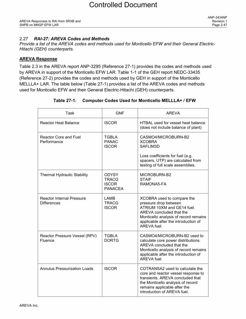
AREVA Response Table 2.3 in the AREVA report ANP-3295 (Reference 27-1) provides the codes and methods used by AREVA in support of the Monticello EFW LAR. Table 1-1 of the GEH report NEDC-33435 (Reference 27-2) provides the codes and methods used by GEH in support of the Monticello MELLLA+ LAR. The table below (Table 27-1) provides a list of the AREVA codes and methods used for Monticello EFW and their General Electric-Hitachi (GEH) counterparts.
Table 27-1. Computer Codes Used for Monticello MELLLA+ / EFW
Task GNF AREVA
Reactor Heat Balance ISCOR HTBAL used for vessel heat balance (does not include balance of plant)
Reactor Core and Fuel Performance
TGBLA PANAC ISCOR
CASMO4/MICROBURN-B2 XCOBRA SAFLIM3D
Loss coefficients for fuel (e.g. spacers, UTP) are calculated from testing of full scale assemblies.
Thermal Hydraulic Stability ODYSY TRACG ISCOR PANACEA
MICROBURN-B2 STAIF RAMONA5-FA
Reactor Internal Pressure Differences
LAMB TRACG ISCOR
XCOBRA used to compare the pressure drop between ATRIUM 10XM and GE14 fuel. AREVA concluded that the Monticello analysis of record remains applicable after the introduction of AREVA fuel.
Reactor Pressure Vessel (RPV) Fluence
TGBLA DORTG
CASMO4/MICROBURN-B2 used to calculate core power distributions. AREVA concluded that the Monticello analysis of record remains applicable after the introduction of AREVA fuel.
Annulus Pressurization Loads ISCOR COTRANSA2 used to calculate the core and reactor vessel response to transients. AREVA concluded that the Monticello analysis of record remains applicable after the introduction of AREVA fuel.
AREVA Inc.
Controlled Document

AREVA Responses to RAI from SRXB and SNPB on MNGP EFW LAR
ANP-3434NP Revision 1 Page 2-48
Task GNF AREVA
Transient Analyses PANAC ODYN ISCOR TASC TRACG04
RODEX2 (gap coefficient for COTRANSA2 & XCOBRA-T) RODEX4 (fuel rod T-M) COTRANSA2 XCOBRA XCOBRA-T
Anticipated Transients Without Scram (ATWS)
ODYN STEMP PANACEA TASC ISCOR TRACG
COTRANSA2 (peak pressure) AISHA (ATWS Instability) SINANO (ATWS Instability)
Containment System Response M3CPT LAMB
COTRANSA2 used to calculate the core and reactor vessel response to transients (energy released from SRV).
CASMO4/MICROBURN-B2 used to compare key parameters between ATRIUM 10XM and GE14 fuel (void coefficient, doppler coefficient, boron worth)
XCOBRA used to compare hydraulic performance of ATRIUM 10XM and GE14 fuel.
AREVA reviewed the licensing basis containment analysis and compared the key parameters between ATRIUM 10XM and GE14 fuel. AREVA concluded that the Monticello analysis of record remains applicable after the introduction of AREVA fuel.
Reactor Recirculation System BILBO The performance of the recirculation system is modeled in all codes used for transient analyses. The Monticello recirculation piping is modeled and the performance of the Monticello jet pumps and recirculation pumps is modeled.
ECCS-Loss of Coolant Accident (LOCA)
LAMB GESTR SAFER ISCOR TASC
RODEX2 RELAX HUXY
AREVA Inc.
Controlled Document

AREVA Responses to RAI from SRXB and SNPB on MNGP EFW LAR
ANP-3434NP Revision 1 Page 2-49
References for RAI-27
27-1. ANP-3295P Revision 2, Monticello Licensing Analysis For EFW (EPU/MELLLA+), AREVA Inc, September 2014. (transmitted to NRC as part of the EFW transition LAR)
27-2. GEH Report, “Safety Analysis Report for Monticello Regarding Maximum Extended Load Line Limit Analysis Plus”, NEDC-33435P Revision 1, December 2009.
AREVA Inc.
Controlled Document

AREVA Responses to RAI from SRXB and SNPB on MNGP EFW LAR
ANP-3434NP Revision 1 Page 2-50
2.28 RAI-28 SLMCPR Calculation in the EFW Region Provide a justification for the core flow rate, assembly radial peaking, and nodal power uncertainties used to calculate SLMCPR at the EFW corners.
AREVA Response
• Core flow rate uncertainty - In the SLMCPR analyses for Monticello MELLLA+ performed by GNF, the core flow uncertainty applied for single-loop operation was also applied to the SLMCPR analyses for the minimum core flow at rated power (point “L” in Figure 28-1) and for the minimum core flow along the MELLLA+ boundary (point “M” in Figure 28-1). Due to lower core flows in the MELLLA+ domain (when compared to the EPU/MELLLA domain), this precedent was followed for the AREVA EFW SLMCPR calculations that were performed for the statepoints identified as “L” and “M” as reported in Section 4.2 of Reference 28-1. This is applicable for EFW since this is the same operating domain expansion as MELLLA+.
• Assembly radial peaking, and nodal power uncertainties - The power distribution uncertainties determined by Xcel Energy to be applicable to the MNGP Gardel core monitoring system are used in the AREVA SLMCPR calculations. As summarized in the response to RAI-10, AREVA has experience up to [ ]. As illustrated in Figure 28-1, the EFW region of the MNGP power/flow map is always less than [ ]. Based on the similarity between the AREVA and the Gardel neutronics models (CASMO-4/MICROBURN-B2 and CASMO4/SIMULATE), the power distribution uncertainties used in the AREVA SLMCPR analyses are expected to be applicable for MNGP operation in the EFW region. The response to RAI-2 summarizes the process for collecting MNGP TIP data in the EFW domain and how these TIP measurements will be reflected in future AREVA SLMCPR calculations.
References for RAI-28 28-1. ANP-3295P Revision 2, Monticello Licensing Analysis For EFW (EPU/MELLLA+), AREVA Inc,
September 2014. (transmitted to NRC as part of the EFW transition LAR)
AREVA Inc.
Controlled Document

AREVA Responses to RAI from SRXB and SNPB on MNGP EFW LAR
ANP-3434NP Revision 1 Page 2-51
Figure 28-1. Monticello Power/Flow map [ ]
AREVA Inc.
Controlled Document

AREVA Responses to RAI from SRXB and SNPB on MNGP EFW LAR
ANP-3434NP Revision 1 Page 2-52
2.29 RAI-29: Benchmarks Against Plant Transients Provide benchmarks of analytical suite against modern transients (e.g., Susquehanna recirculation runback) to justify extension of methods.
AREVA Response AREVA uses the COTRANSA2 code for modeling the vessel and core response during transient analyses. Benchmarks to three turbine trip tests conducted at Peach Bottom Unit 2 are provided in the COTRANSA2 topical report, Reference 29-1, Supplement 2.
COTRANSA2 was benchmarked to a more modern transient in response to a previous NRC RAI, Reference 29-2, page 6-16. COTRANSA2 was compared to an event that occurred at one of the Susquehanna units in 2008, which was after they received approval for EPU operation. The event involved a reduction in pump speed in one of the recirculation loops followed by a sudden increase in the pump speed approximately 40 seconds later. The event did not pose a challenge to the fuel. For this analysis, a best estimate approach was used and event specific licensing conservatisms were not applied (e.g., measured data used as boundary conditions, realistic control system parameters, best estimate core neutronics data). The recirculation pump speed versus time from the plant data was used as a boundary condition for the analysis (Figure 29-1). The COTRANSA2 analysis predicted the core power and reactor pressure response very well (Figure 29-2 and Figure 29-3).
References for RAI-29
29-1. ANF-913(P)(A) Volume 1 Revision 1 and Volume 1 Supplements 2, 3 and 4, COTRANSA2: A Computer Program for Boiling Water Reactor Transient Analyses, Advanced Nuclear Fuels Corporation, August 1990.
29-2. ANP-2860P Revision 2, Browns Ferry Unit 1 – Summary of Responses to Requests for Additional Information, AREVA, October 2009. (ADAMS Accession No. ML101160516)
AREVA Inc.
Controlled Document

AREVA Responses to RAI from SRXB and SNPB on MNGP EFW LAR
ANP-3434NP Revision 1 Page 2-53
Figure 29-1. COTRANSA2 Benchmark - Pump Speed
Figure 29-2. COTRANSA2 Benchmark - Core Power
AREVA Inc.
Controlled Document

AREVA Responses to RAI from SRXB and SNPB on MNGP EFW LAR
ANP-3434NP Revision 1 Page 2-54
Figure 29-3. COTRANSA2 Benchmark - Reactor Pressure
AREVA Inc.
Controlled Document
AREVA Responses to RAI from SRXB and SNPB on MNGP EFW LAR
ANP-3434NP Revision 1 Page 2-55
2.30 RAI-30: Figures of Merit for Limiting Cases Provide a Table of figures of merit of the most limiting cases for ATWSI, ATWS, Overpressure, transients, and LOCA. This comparison is required to identify the limiting cases for each core loading (GE-14, ATRIUM 10XM and GE-14, and ATRIUM 10XM).
AREVA Response AREVA report ANP-3295 (Reference 30-1) provides the figures of merit for ATWS pressurization transient (Table 7.2), ASME overpressure (Table 7.1), transients (Tables 5.1, 5.4, 5.5, 5.6, 5.7, 5.8, 5.9 and 5.11) and LOCA (Table 6.2). All transients, ASME overpressure and ATWS pressurization were performed for the first transition core to ATRIUM 10XM. The LOCA analysis considers a full core of ATRIUM 10XM fuel.
Table 30-1 below provides a summary of the most important figures of merit.
References for RAI-30
30-1. ANP-3295P Revision 2, Monticello Licensing Analysis For EFW (EPU/MELLLA+), AREVA Inc, September 2014. (transmitted to NRC as part of the EFW LAR)
AREVA Inc.
Controlled Document

AREVA Responses to RAI from SRXB and SNPB on MNGP EFW LAR
ANP-3434NP Revision 1 Page 2-56
Table 30-1. Comparison of GNF and AREVA Results for the Representative Cycle 28 (MELLLA+ / EFW)
]
[
AREVA Inc.
Controlled Document
AREVA Responses to RAI from SRXB and SNPB on MNGP EFW LAR
ANP-3434NP Revision 1 Page 2-57
2.31 RAI-31: O-III Versus EO-III Setpoints Provide a discussion of the process followed by AREVA to ensure that the Enhanced Option III (EO-III) setpoints are conservative with respect to the Boiling Water Reactor Owners Group (BWROG) Option III setpoints
AREVA Response The method for developing OPRM setpoints available in the MNGP licensing basis is the EO-III method described in the AREVA LTR ANP-10262PA (Reference 34-1). The use of the EO-III at MNGP can be logically shown to provide a limiting (more restrictive) setpoint based on the following discussion. The evaluations performed for the EO-III solution are an extension of the Option III evaluations. The differences in evaluations performed are limited to differences in state points provided and accounting for the possibility of higher EFW decay ratios. For any stability solution, the most limiting event will be an event that puts the core at the most unstable point. For the Option III stability solution, this meant that the evaluations were done at natural circulation at the highest licensed rod line (MELLLA line). For EO-III with EFW, the core may not be able to reach the intersection of EFW rod line and natural circulation due to the channel instability region scram. Instead, Enhanced Option III looks at two potentially limiting points, the intersection of channel exclusion region with both natural circulation flow line and the EFW rod line. These two points serve the same purpose as performing analyses at the MELLLA rod line and natural circulation flow for Option III, i.e. to put the core deeper into the instability region. Since the calculated channel exclusion region is above the MELLLA line, the Enhanced Option III analyses will cover any Option III analyses done within the MELLLA boundaries. [
]
References for RAI-31 34-1. ANP-10262(P)(A) Revision 0, Enhanced Option III Long Term Stability Solution, May 2008.
AREVA Inc.
Controlled Document

AREVA Responses to RAI from SRXB and SNPB on MNGP EFW LAR
ANP-3434NP Revision 1 Page 2-58
2.32 RAI-32: 2RPT ATWS The ATWSI analysis of record in the LAR is Turbine Trip with Bypass (TTWBP). When operator actions are credited, the TTWBP does not show significant power oscillations and the limiting ATWSI transient becomes the 2RPT with failure to scram.
Provide the results of 2RPT event with failure to scram. Describe the basis for boundary conditions and operator actions assumed for the analysis.
AREVA Response To be provided at a later date in a different AREVA report (ANP-3435).
AREVA Inc.
Controlled Document

AREVA Responses to RAI from SRXB and SNPB on MNGP EFW LAR
ANP-3434NP Revision 1 Page 2-59
2.33 RAI-33: Reactivity Model Section 2.6 of ANP-3274P indicates that as density wave propagates upward, the total reactivity as well as the axial reactivity distribution changes and there are oscillating reactivity differences between the upper and the lower parts of the core.
(a) Provide an estimate of the magnitude of the change in reactivity between the upper and lower part of the core and the frequency with which the change occurs.
(b) Explain the impact of the reactivity swing between the upper and lower parts of the core on the ATWS instability event.
(c) Explain how this swing in the reactivity in axial mode is accounted for by the neutron kinetics model used in the analysis.
AREVA Response (a) Provide an estimate of the magnitude of the change in reactivity between the upper and lower
part of the core and the frequency with which the change occurs.
[
]
(b) Explain the impact of the reactivity swing between the upper and lower parts of the core on the
ATWS instability event.
[
]
AREVA Inc.
Controlled Document

AREVA Responses to RAI from SRXB and SNPB on MNGP EFW LAR
ANP-3434NP Revision 1 Page 2-60
(c) Explain how this swing in the reactivity in axial mode is accounted for by the neutron kinetics model used in the analysis.
[
]
AREVA Inc.
Controlled Document

AREVA Responses to RAI from SRXB and SNPB on MNGP EFW LAR
ANP-3434NP Revision 1 Page 2-61
2.34 RAI-34: ATWSI Analysis Assumptions Provide a justification for the differences in the assumptions listed in Section 5 of Calculation notebook 32-9196882-001, “Monticello ATWS/INSTABILITY ANALYSES,” and Section A.2.1 of ANP-3274P.
AREVA Response The Monticello ATWS/Instability Analyses are internally documented in FS1-0015423. Section 5 of this calculation notebook documents the key input and modeling assumptions made in the final ATWSi analyses. These assumptions are also summarized in the Section 4.0 text of ANP-3284P (Reference 34-1). This report provides the benchmarking and calculation results of the ATWSi codes.
The report ANP-3274P (Reference 34-2) is focused on the description of the new codes and methods that have been developed for ATWSi. Section A.2.1 of ANP-3274P gives the assumptions that were made during the development of the AISHA code, with a justification for each assumption. Since these assumptions have already been justified as insignificant or conservative, there was no need to repeat them in FS1-0015423.
References for RAI-34
34-1. ANP-3284P Revision 0, Results of Analysis and Benchmarking of Methods for Monticello ATWS-I, AREVA, April 2014. (transmitted to NRC as part of the EFW LAR)
34-2. ANP-3274P Revision 0, Analytical Methods for Monticello ATWS-I, AREVA, April 2014. (transmitted to NRC as part of the EFW LAR)
AREVA Inc.
Controlled Document

AREVA Responses to RAI from SRXB and SNPB on MNGP EFW LAR
ANP-3434NP Revision 1 Page 2-62
2.35 RAI-35: Gd Rod Treatment in Hot Rod Selection The ANP-3139P indicates that there will be Gadolinia (Gd) rods in the MNGP core.
Describe the impact, if any, of Gd rods on the selection of average power rod and peak power-hot rod. Provide a justification for this treatment, or lack thereof, given that the melting temperature of Gad rods is less than a pure uranium oxide rod.
AREVA Response As pointed out by the reviewer, the gadolinia (Gd) rods can be limiting when establishing the LHGR limits and multipliers to protect the acceptance criteria for steady state operation and AOOs. The RODEX4 code takes into account thermal conductivity degradation with dependencies on both exposure and gadolinia content. In addition, the thermal-mechanical methodology associated with RODEX4 for normal operation and AOOs, incorporates a decrease in melting temperature as a function of gadolinia content. These features of the RODEX4 code and methodology were reviewed and approved as part of the RODEX4 topical report, Reference 35-1. The urania and gadolinia fuel within a fuel assembly are analyzed and monitored to the same linear heat generation rate (LHGR) limit. Plant- and cycle-specific analyses are performed on the specified nuclear design to ensure that the fuel melting temperature criterion along with other fuel rod design criteria are satisfied. If during the design process a gadolinia rod is found to fail the design criteria, then changes are made to the nuclear design to lower the local peaking of the gadolinia rod until the design criteria are satisfied. The result is a design that meets the thermal-mechanical criteria using LHGR limits that will be applied during subsequent operation of the fuel. In the case of an LHGR-limited fuel assembly, the fuel assembly power will be restricted by the LHGR of the highest powered fuel rod in the fuel assembly. Normally, a urania fuel rod will have the lowest margin to the LHGR limit within the fuel assembly. It is also normal in the enrichment distribution design to include enrichment reductions in the gadolinia fuel to accommodate higher fuel rod power peaking after the gadolinia is depleted. However, it is still possible for a gadolinia fuel rod to become LHGR-limiting within the fuel assembly at some point in a cycle. For example, a fuel rod with low gadolinia concentration and relatively high enrichment could achieve a higher power level at intermediate exposure levels. Such situations are explicitly considered in the RODEX4 methodology, which statistically examines all of the fuel rods in the cycle design.
For AOOs AREVA sets power dependent LHGR multipliers (LHGRFACp). These multipliers are less than one and effectively reduce the LHGR limits of the rods in order to protect the centerline melting temperature of both gadolinia and non-gadolinia rods and strain criteria during the transients. The Monticello EFW LHGRFACp multipliers are provided in Section 8.0 of the report ANP-3295 (Reference 35-2).
For accidents and special events, centerline melting of pellets is not among the acceptance criteria (References 35-3 – 35-9).
AREVA Inc.
Controlled Document
AREVA Responses to RAI from SRXB and SNPB on MNGP EFW LAR
ANP-3434NP Revision 1 Page 2-63
References for RAI-35 35-1. BAW-10247PA Revision 0, Realistic Thermal-Mechanical Fuel Rod Methodology for Boiling Water
Reactors, AREVA NP, February 2008.
35-2. ANP-3295P Revision 2, Monticello Licensing Analysis For EFW (EPU/MELLLA+), AREVA Inc, September 2014. (transmitted to NRC as part of the EFW LAR)
35-3. Monticello Nuclear Generating Plant Updated Safety Analysis Report
35-4. Monticello Nuclear Generating Plant Technical Specifications
35-5. Monticello Nuclear Generating Plant Technical Specifications (Bases)
35-6. GEH Report, “Safety Analysis Report for Monticello Constant Pressure Power Uprate”, NEDC-33322P Revision 3, October 2008.
35-7. GEH Report, “Safety Analysis Report for Monticello Regarding Maximum Extended Load Line Limit Analysis Plus”, NEDC-33435P Revision 1, December 2009.
35-8. Letter from T. A. Beltz (NRC) to K. D. Fili (Xcel Energy), “Monticello Nuclear Generating Plant – Issuance of Amendment No. 176 To Renewed Facility Operating License Regarding Extended Power Uprate (TAC No. MD9990),” December 9, 2013. (ADAMS Accession No. ML13316B298)
35-9. Letter from T. A. Beltz (NRC) to K. D. Fili (Xcel Energy), “Monticello Nuclear Generating Plant – Issuance of Amendment No. 180 To Renewed Facility Operating License Regarding Maximum Extended Load Line Limit Analysis Plus (TAC No. ME3145),” March 28, 2014. (ADAMS Accession No. ML14035A248)
AREVA Inc.
Controlled Document

AREVA Responses to RAI from SRXB and SNPB on MNGP EFW LAR
ANP-3434NP Revision 1 Page 2-64
2.36 RAI-36: Heater Rods Versus Fuel Rods (a) Provide a comparison between the test rods used in KATHY facility to the actual rods of GE-14
and ATRIUM 10XM fuel, including similarities and differences.
(b) Explain how the differences between KATHY test rods and actual fuel rods impacts the benchmarking of the MNGP ATWSI analysis that is modelled using the AISHA/SINANO methodology. Include a discussion of the impact of using stainless steel rods and using skin heater rods.
AREVA Response (a) Provide a comparison between the test rods used in KATHY facility to the actual rods of GE-14
and ATRIUM 10XM fuel, including similarities and differences.
The heater rods in the KATHY loop testing of the ATRIUM 10XM have identical outer diameter to the actual fuel rods. [
]
The differences between the nuclear fuel rod (ATRIUM 10XM or GE14) and the heater rod are:
• [
]
AREVA Inc.
Controlled Document

AREVA Responses to RAI from SRXB and SNPB on MNGP EFW LAR
ANP-3434NP Revision 1 Page 2-65
• [ ]
(b) Explain how the differences between KATHY test rods and actual fuel rods impacts the benchmarking of the MNGP ATWSI analysis that is modelled using the AISHA/SINANO methodology. Include a discussion of the impact of using stainless steel rods and using skin heater rods.
[
]
AREVA Inc.
Controlled Document

AREVA Responses to RAI from SRXB and SNPB on MNGP EFW LAR
ANP-3434NP Revision 1 Page 2-66
2.37 RAI-37: SINANO Benchmarking Process: Please provide a summary of how the stability is determined for tests that include stable operation under different power and subcooling conditions using “noise analysis techniques” as mentioned in Section 3.0 of ANP-3284.
AREVA Response AISHA was benchmarked against stability tests in KATHY loop and regional instability events in reactors. [
]
The noise analysis codes are:
• [
]
[
]
References for RAI-37
37-1. ANF-1161(P)(A) “ANNA: Advanced Neutron Noise Analysis Software System,” April 1990.
37-2. J. March-Leuba, “Dynamic Behavior of Boiling Water Reactors,” The University of Tennessee, Ph.D. Thesis, 1984 (Chapter 5).
37-3. Y. M. Farawila et al., “Methodologies and Results Presented by Siemens,” Annex 7 of “Forsmark 1 & 2 Boiling Water Reactor Stability Benchmark -- Time Series Analysis Methods for Oscillation during BWR Operation,” Final Report, OECD report NEA/NSC/DOC(2001)2, June 2001.
AREVA Inc.
Controlled Document

AREVA Responses to RAI from SRXB and SNPB on MNGP EFW LAR
ANP-3434NP Revision 1 Page A-1
Appendix A
NEDC-33435P, “Safety Analysis Report for Monticello Maximum Extended Load Line Limit Analysis Plus,” dated December 2009,
Disposition of additional limitations and conditions related to the final SE for NEDC-33173P, "Applicability of GE Methods to Expanded Operating Domains"
Limitation
and Condition Number
from NRC SER
Limitation and Condition Title
Limitation and Condition Description
Applicability to AREVA Methods
9.1 TGBLA/PANAC Version
The neutronic methods used to simulate the reactor core response and that feed into the downstream safety analyses supporting operation at EPU/MELLLA+ will apply TGBLA06/PANAC11 or later NRC-approved version of neutronic method.
Not Applicable AREVA is using the most current NRC approved neutronics methods (CASMO4/MICROBURN-B2 method (EMF-2158(P)(A))).
9.2 3D Monicore For EPU/MELLLA+ applications, relying on TGBLA04/PANAC10 methods, the bundle RMS difference uncertainty will be established from plant-specific core-tracking data, based on TGBLA04/PANAC10. The use of plant-specific trendline based on the neutronic method employed will capture the actual bundle power uncertainty of the core monitoring system.
Applicable Xcel Energy uses the Gardel core monitoring system at Monticello. The uncertainties determined by Xcel Energy to be applicable to the Monticello Gardel core monitoring system are used in the statistical analyses that are performed by AREVA (SLMCPR and LHGR).
9.3 Power/Flow Ratio
Plant-specific EPU and expanded operating domain applications will confirm that the core thermal power to core flow ratio will not exceed 50 MWt/Mlbm/hr at any statepoint in the allowed operating domain. For plants that exceed the power-to-flow value of 50 MWt/Mlbm/hr, the application will provide power distribution assessment to establish that neutronic methods axial and nodal power distribution uncertainties have not increased.
Applicable Existing confirmation is applicable.
9.4 SLMCPR 1 For EPU operation, a 0.02 value shall be added to the cycle-specific SLMCPR value. This adder is applicable to SLO, which is derived from the dual loop SLMCPR value.
Not Applicable AREVA performs statistical analyses with SLO uncertainties to establish the SLO SLMCPR. NRC did not impose an adder during the review and approval of the transition to AREVA fuel and methods for Monticello (Reference A1). This was consistent with previous reviews of AREVA methods for EPU (Susquehanna & Brunswick). MNGP uses neutron TIPs as does Susquehanna.
AREVA Inc.
Controlled Document

AREVA Responses to RAI from SRXB and SNPB on MNGP EFW LAR
ANP-3434NP Revision 1 Page A-2
Limitation and
Condition Number
from NRC SER
Limitation and Condition Title
Limitation and Condition Description
Applicability to AREVA Methods
9.5 SLMCPR 2 For operation at MELLLA+, including operation at the EPU power levels at the achievable core flow statepoint, a 0.03 value shall be added to the cycle-specific SLMCPR value.
Not Applicable Monticello will be the first application of AREVA methods to MELLLA+. The ongoing NRC review for Monticello EFW will establish what SLMCPR penalties, if any, are applicable.
9.6 R-Factor The plant specific R-factor calculation at a bundle level will be consistent with lattice axial void conditions expected for the hot channel operating state. The plant-specific EPU/MELLLA+ application will confirm that the R-factor calculation is consistent with the hot channel axial void conditions.
Applicable The corresponding factors are Feff for SPCB (used for GE14) and K-factor for ACE (used for XM). These factors account for the conditions calculated within the bundle (pin power reconstruction).
9.7 ECCS-LOCA 1 For applications requesting implementation of EPU or expanded operating domains, including MELLLA+, the small and large break ECCSLOCA analyses will include top-peaked and mid-peaked power shape in establishing the MAPLHGR and determining the PCT. This limitation is applicable to both the licensing bases PCT and the upper bound PCT. The plant-specific applications will report the limiting small and large break licensing basis and upper bound PCTs.
Applicable AREVA LOCA calculations include top-peaked and mid-peaked power shape. AREVA does not calculate upper bound PCT. AREVA calculates large and small break PCTs. Monticello LOCA calculations for EFW conditions are summarized in Section 6.1 of ANP-3295.
9.8 ECCS-LOCA 2 The ECCS-LOCA will be performed for all statepoints in the upper boundary of the expanded operating domain, including the minimum core flow statepoints, the transition statepoint, as defined in Reference A-2* and the 55 percent core flow statepoint. The plant-specific application will report the limiting ECCS-LOCA results as well as the rated power and flow results. The SRLR will include both the limiting statepoint ECCS-LOCA results and the rated conditions ECCS-LOCA results.
Applicable AREVA LOCA calculations were performed for the maximum and minimum core flow at rated EPU power and the low core flow MELLLA+ boundary. Results for the maximum and minimum core flow at rated EPU power and both axial power shapes are summarized in the Break Spectrum report (ANP-3211) which was included in the fuel transition LAR. Results for the low core flow MELLLA+ boundary and both axial power shapes are summarized in Section 6.1 of ANP-3295 (this statepoint replaces the “transition” statepoint).
* The references in this column are from the original GE document where the limitation occurs. These references are not repeated here, they can be found in the original GE documents.
AREVA Inc.
Controlled Document

AREVA Responses to RAI from SRXB and SNPB on MNGP EFW LAR
ANP-3434NP Revision 1 Page A-3
Limitation and
Condition Number
from NRC SER
Limitation and Condition Title
Limitation and Condition Description
Applicability to AREVA Methods
9.9 Transient LHGR 1
Plant-specific EPU and MELLLA+ applications will demonstrate and document that during normal operation and core-wide AOOs, the T-M acceptance criteria as specified in Amendment 22 to GESTAR II will be met. Specifically, during an AOO, the licensing application will demonstrate that the: (1) loss of fuel rod mechanical integrity will not occur due to fuel melting and (2) loss of fuel rod mechanical integrity will not occur due to pellet–cladding mechanical interaction. The plant-specific application will demonstrate that the T-M acceptance criteria are met for the both the UO2 and the limiting GdO2 rods.
Applicable AREVA demonstrated and documented that during normal operation and core-wide AOOs, the T-M acceptance criteria will be met. AREVA uses the most recent NRC approved T-M method described in BAW-10247PA. This method includes models that account for pellet thermal conductivity degradation. The power and flow dependent LHGRFAC multipliers are summarized in Sections 5 and 8 of ANP-3295, which was included in the EFW LAR.
9.10 Transient LHGR 2
Each EPU and MELLLA+ fuel reload will document the calculation results of the analyses demonstrating compliance to transient T-M acceptance criteria. The plant T-M response will be provided with the SRLR or COLR, or it will be reported directly to the NRC as an attachment to the SRLR or COLR.
Applicable Compliance to transient T-M acceptance is documented in Sections 5 and 8 of ANP-3295. T-M calculations will be performed each cycle and the resulting limits will be reported to Xcel Energy in the cycle specific licensing analysis report (e.g. ANP-3295).
9.11 Transient LHGR 3
To account for the impact of the void history bias, plant-specific EPU and MELLLA+ applications using either TRACG or ODYN will demonstrate an equivalent to 10 percent margin to the fuel centerline melt and the 1 percent cladding circumferential plastic strain acceptance criteria due to pellet-cladding mechanical interaction for all of limiting AOO transient events, including equipment out-of-service. Limiting transients in this case, refers to transients where the void reactivity coefficient plays a significant role (such as pressurization events). If the void history bias is incorporated into the transient model within the code, then the additional 10 percent margin to the fuel centerline melt and the 1 percent cladding circumferential plastic strain is no longer required.
Not Applicable For GE14 fuel AREVA used the GEH MOP/TOP criteria. For XM fuel AREVA used the most current NRC approved T-M methods described in the BAW-10247PA. The response to RAI-29 compares the transient response predicted by COTRANSA2 to measured data for a modern transient.
AREVA Inc.
Controlled Document

AREVA Responses to RAI from SRXB and SNPB on MNGP EFW LAR
ANP-3434NP Revision 1 Page A-4
Limitation and
Condition Number
from NRC SER
Limitation and Condition Title
Limitation and Condition Description
Applicability to AREVA Methods
9.12 LHGR and Exposure Qualification
In MFN 06-481, GE committed to submit plenum fission gas and fuel exposure gamma scans as part of the revision to the T-M licensing process. The conclusions of the plenum fission gas and fuel exposure gamma scans of GE 10x10 fuel designs as operated will be submitted for NRC staff review and approval. This revision will be accomplished through Amendment to GESTAR II or in a T-M licensing LTR. PRIME (a newly developed T-M code) has been submitted to the NRC staff for review (Reference A-3). Once the PRIME LTR and its application are approved, future license applications for EPU and MELLLA+ referencing LTR NEDC-33173P must utilize the PRIME T-M methods.
No Applicable AREVA used the most current NRC approved T-M methods described in BAW-10247PA.
9.13 Application of 10 Weight Percent Gd
Before applying 10 weight percent Gd to licensing applications, including EPU and expanded operating domain, the NRC staff needs to review and approve the T-M LTR demonstrating that the T-M acceptance criteria specified in GESTAR II and Amendment 22 to GESTAR II can be met for steady-state and transient conditions. Specifically, the T-M application must demonstrate that the T-M acceptance criteria can be met for TOP and MOP conditions that bounds the response of plants operating at EPU and expanded operating domains at the most limiting statepoints, considering the operating flexibilities (e.g., equipment out-of-service). Before the use of 10 weight percent Gd for modern fuel designs, NRC must review and approve TGBLA06 qualification submittal. Where a fuel design refers to a design with Gd-bearing rods adjacent to vanished or water rods, the submittal should include specific information regarding acceptance criteria for the qualification and address any downstream impacts in terms of the safety analysis. The 10 weight percent Gd qualifications submittal can supplement this report.
Not Applicable AREVA used the most current NRC approved T-M methods described in the BAW-10247PA and the most current NRC approved neutronics methods described in EMF-2158(P)(A).
AREVA Inc.
Controlled Document

AREVA Responses to RAI from SRXB and SNPB on MNGP EFW LAR
ANP-3434NP Revision 1 Page A-5
Limitation and
Condition Number
from NRC SER
Limitation and Condition Title
Limitation and Condition Description
Applicability to AREVA Methods
9.14 Part 21 Evaluation of GESTR-M Fuel Temperature Calculation
Any conclusions drawn from the NRC staff evaluation of the GE’s Part 21 report will be applicable to the GESTR-M T-M assessment of this SE for future license application. GE submitted the T-M Part 21 evaluation, which is currently under NRC staff review. Upon completion of its review, NRC staff will inform GE of its conclusions.
Not applicable The evaluation of the impact of pellet thermal conductivity degradation on the AREVA methods being used for Monticello is described in Appendix E of ANP-3224 (Reference A2). ANP-3224 was reviewed and approved during the Monticello transition to AREVA for EPU, Reference A1.
9.15 Void Reactivity 1
The void reactivity coefficient bias and uncertainties in TRACG for EPU and MELLLA+ must be representative of the lattice designs of the fuel loaded in the core.
Applicable Related information is provided in response to RAI-9, RAI-21 and RAI-29 and in ANP-3224 (Reference A2).
9.16 Void Reactivity 2
A supplement to TRACG /PANAC11 for AOO is under NRC staff review (Reference A-4). TRACG internally models the response surface for the void coefficient biases and uncertainties for known dependencies due to the relative moderator density and exposure on nodal basis. Therefore, the void history bias determined through the methods review can be incorporated into the response surface “known” bias or through changes in lattice physics/core simulator methods for establishing the instantaneous cross-sections. Including the bias in the calculations negates the need for ensuring that plant-specific applications show sufficient margin. For application of TRACG to EPU and MELLLA+ applications, the TRACG methodology must incorporate the void history bias. The manner in which this void history bias is accounted for will be established by the NRC staff SE approving NEDE- 32906P, Supplement 3, “Migration to TRACG04/PANAC11 from TRACG02/PANAC10,” May 2006 (Reference A-4). This limitation applies until the new TRACG/PANAC methodology is approved by the NRC staff.
Not Applicable The response to RAI-29 compares the transient response predicted by COTRANSA2 to measured data for a modern transient.
AREVA Inc.
Controlled Document

AREVA Responses to RAI from SRXB and SNPB on MNGP EFW LAR
ANP-3434NP Revision 1 Page A-6
Limitation and
Condition Number
from NRC SER
Limitation and Condition Title
Limitation and Condition Description
Applicability to AREVA Methods
9.17 Steady-State 5 Percent Bypass Voiding
The instrumentation specification design bases limit the presence of bypass voiding to 5 percent (LRPM (sic) levels). Limiting the bypass voiding to less than 5 percent for long-term steady operation ensures that instrumentation is operated within the specification. For EPU and MELLLA+ operation, the bypass voiding will be evaluated on a cycle-specific basis to confirm that the void fraction remains below 5 percent at all LPRM levels when operating at steady-state conditions within the MELLLA+ upper boundary. The highest calculated bypass voiding at any LPRM level will be provided with the plant-specific SRLR.
Applicable This is an instrumentation specification. AREVA will comply with this restriction.
9.18 Stability Setpoints Adjustment
The NRC staff concludes that the presence bypass voiding at the low-flow conditions where instabilities are likely can result in calibration errors of less than 5 percent for OPRM cells and less than 2 percent for APRM signals. These calibration errors must be accounted for while determining the setpoints for any detect and suppress long term methodology. The calibration values for the different long-term solutions are specified in the associated sections of this SE, discussing the stability methodology.
Not Applicable Bypass voiding for Monticello during EFW conditions is addressed in the report which addresses the applicability of AREVA methods for EFW (Section 7.1 of ANP-3135P).
9.19 Void-Quality Correlation 1
For applications involving PANCEA/ODYN/ISCOR/TASC for operation at EPU and MELLLA+, an additional 0.01 will be added to the OLMCPR, until such time that GE expands the experimental database supporting the Findlay-Dix void-quality correlation to demonstrate the accuracy and performance of the void-quality correlation based on experimental data representative of the current fuel designs and operating conditions during steady-state, transient, and accident conditions.
Applicable The void quality correlations used in AREVA methods are addressed in Appendix D of Reference A2, which was reviewed and approved during the Monticello transition to AREVA for EPU, Reference A1.
AREVA Inc.
Controlled Document

AREVA Responses to RAI from SRXB and SNPB on MNGP EFW LAR
ANP-3434NP Revision 1 Page A-7
Limitation and
Condition Number
from NRC SER
Limitation and Condition Title
Limitation and Condition Description
Applicability to AREVA Methods
9.20 Void-Quality Correlation 2
The NRC staff is currently reviewing Supplement 3 to NEDE-32906P, “Migration to TRACG04/PANAC11 from TRACG02/PANAC10,” dated May 2006 (Reference A-4). The adequacy of the TRACG interfacial shear model qualification for application to EPU and MELLLA+ will be addressed under this review. Any conclusions specified in the NRC staff SE approving Supplement 3 to LTR NEDC- 32906P (Reference A-4) will be applicable as approved.
Not applicable
9.21 Mixed Core Method 1
Plants implementing EPU or MELLLA+ with mixed fuel vendor cores will provide plant-specific justification for extension of GE’s analytical methods or codes. The content of the plant-specific application will cover the topics addressed in this SE as well as subjects relevant to application of GE’s methods to legacy fuel. Alternatively, GE may supplement or revise LTR NEDC-33173P (Reference A-1) for mixed core application.
Monticello implemented EPU and MELLLA+ with a full core of GE14 fuel.
9.22 Mixed Core Method 2
For any plant-specific applications of TGBLA06 with fuel type characteristics not covered in this review, GE needs to provide assessment data similar to that provided for the GE fuels. The Interim Methods review is applicable to all GE lattices up to GE14. Fuel lattice designs, other than GE lattices up to GE14, with the following characteristics are not covered by this review: • square internal water channels water crosses • Gd rods simultaneously adjacent to water and vanished rods • 11x11 lattices • MOX fuel The acceptability of the modified epithermal slowing down models in TGBLA06 has not been demonstrated for application to these or other geometries for expanded operating domains. Significant changes in the Gd rod optical thickness will require an evaluation of the TGBLA06 radial flux and Gd depletion modeling before being applied. Increases in the lattice Gd loading that result in nodal reactivity biases beyond those
Applicable Mixed core issues for GE14 and ATRIUM 10XM fuel were reviewed in support of the Monticello fuel transition LAR which was approved by the NRC in June 2015. The thermal hydraulic characteristics of GE14 and ATRIUM 10XM fuel were compared and determined to be very similar in Reference A3, which was reviewed and approved during the Monticello transition to AREVA for EPU, Reference A1. The thermal-hydraulic compatibility for GE14 and ATRIUM 10XM fuel is also provided for EFW conditions in Section 4.1 of ANP-3295. AREVA has analyzed a mixed core of GE14 and ATRIUM 10XM fuel in support of the EFW LAR which is currently under NRC review. During the audit that was performed in Richland June 15 – 19, 2015, the NRC
AREVA Inc.
Controlled Document
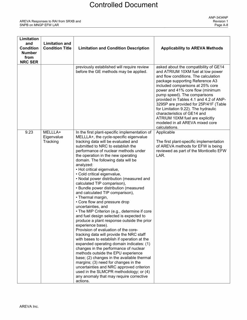
AREVA Responses to RAI from SRXB and SNPB on MNGP EFW LAR
ANP-3434NP Revision 1 Page A-8
Limitation and
Condition Number
from NRC SER
Limitation and Condition Title
Limitation and Condition Description
Applicability to AREVA Methods
previously established will require review before the GE methods may be applied.
asked about the compatibility of GE14 and ATRIUM 10XM fuel at low power and flow conditions. The calculation package supporting Reference A3 included comparisons at 25% core power and 41% core flow (minimum pump speed). The comparisons provided in Tables 4.1 and 4.2 of ANP-3295P are provided for 25P/41F (Table for Limitation 9.22). The hydraulic characteristics of GE14 and ATRIUM 10XM fuel are explicitly modeled in all AREVA mixed core calculations.
9.23 MELLLA+ Eigenvalue Tracking
In the first plant-specific implementation of MELLLA+, the cycle-specific eigenvalue tracking data will be evaluated and submitted to NRC to establish the performance of nuclear methods under the operation in the new operating domain. The following data will be analyzed: • Hot critical eigenvalue, • Cold critical eigenvalue, • Nodal power distribution (measured and calculated TIP comparison), • Bundle power distribution (measured and calculated TIP comparison), • Thermal margin, • Core flow and pressure drop uncertainties, and • The MIP Criterion (e.g., determine if core and fuel design selected is expected to produce a plant response outside the prior experience base). Provision of evaluation of the core-tracking data will provide the NRC staff with bases to establish if operation at the expanded operating domain indicates: (1) changes in the performance of nuclear methods outside the EPU experience base; (2) changes in the available thermal margins; (3) need for changes in the uncertainties and NRC approved criterion used in the SLMCPR methodology; or (4) any anomaly that may require corrective actions.
Applicable The first plant-specific implementation of AREVA methods for EFW is being reviewed as part of the Monticello EFW LAR.
AREVA Inc.
Controlled Document

AREVA Responses to RAI from SRXB and SNPB on MNGP EFW LAR
ANP-3434NP Revision 1 Page A-9
Limitation and
Condition Number
from NRC SER
Limitation and Condition Title
Limitation and Condition Description
Applicability to AREVA Methods
9.24 Plant-Specific Application
The plant-specific applications will provide prediction of key parameters for cycle exposures for operation at EPU (and MELLLA+ for MELLLA+ applications). The plant-specific prediction of these key parameters will be plotted against the EPU Reference Plant experience base and MELLLA+ operating experience, if available. For evaluation of the margins available in the fuel design limits, plant-specific applications will also provide quarter core map (assuming core symmetry) showing bundle power, bundle operating LHGR, and MCPR for BOC, MOC, and EOC. Since the minimum margins to specific limits may occur at exposures other than the traditional BOC, MOC, and EOC, the data will be provided at these exposures.
Applicable The first plant-specific implementation of AREVA methods for EFW is being reviewed as part of the Monticello EFW LAR.
References for Appendix A
A1. Letter from T. A. Beltz (NRC) to P. A. Gardner (Xcel Energy), “Monticello Nuclear Generating Plant – Issuance of Amendment to Transition to AREVA ATRIUM 10XM Fuel and AREVA Safety Analysis Methods (TAC NO. MF2479), June 5, 2015. (ADAMS Accession No. ML 15072A141)
A2. ANP-3224P Revision 2, Applicability of AREVA NP BWR Methods to Monticello, June 2013. (transmitted to NRC as part of the fuel transition LAR)
A3. ANP-3092(P) Revision 0, Monticello Thermal-Hydraulic Design Report for ATRIUM™ 10XM Fuel Assemblies, July 2012. (transmitted to NRC as part of the fuel transition LAR)
AREVA Inc.
Controlled Document

AREVA Responses to RAI from SRXB and SNPB on MNGP EFW LAR
ANP-3434NP Revision 1 Page A-10
Table for Limitation 9.22
Thermal-Hydraulic Results at Off-Rated Conditions (25%P / 41%F)
AREVA Inc.
Controlled Document
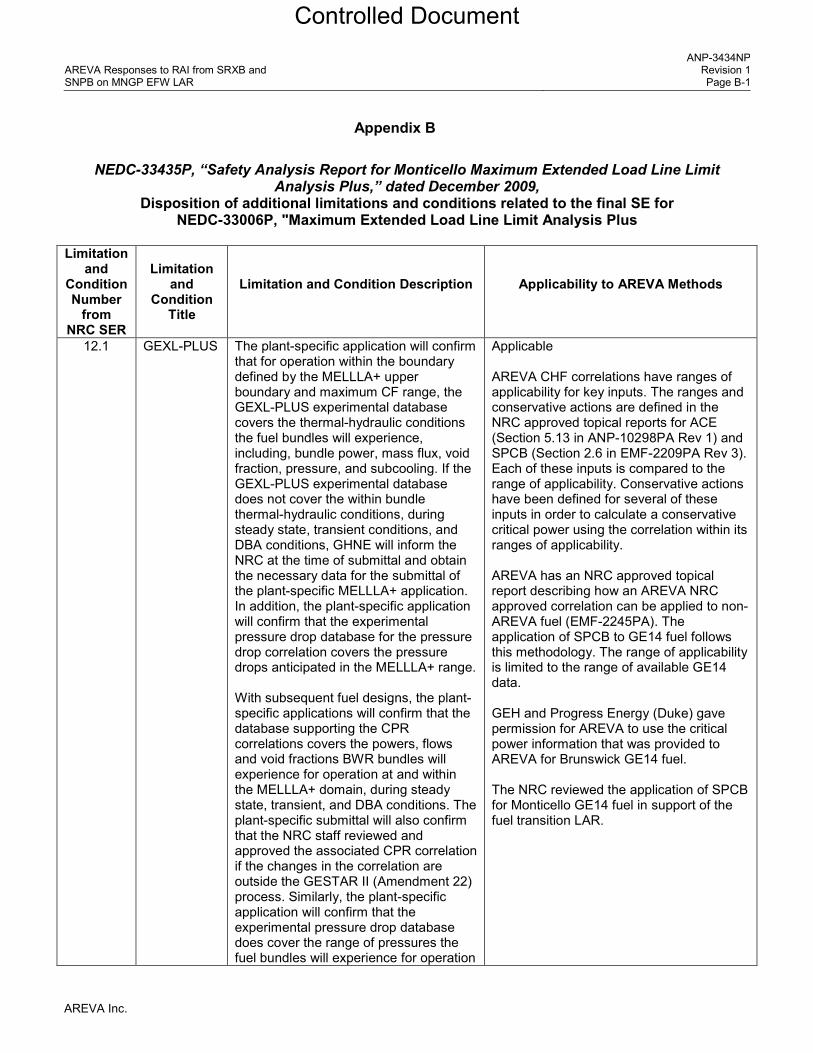
AREVA Responses to RAI from SRXB and SNPB on MNGP EFW LAR
ANP-3434NP Revision 1 Page B-1
Appendix B
NEDC-33435P, “Safety Analysis Report for Monticello Maximum Extended Load Line Limit Analysis Plus,” dated December 2009,
Disposition of additional limitations and conditions related to the final SE for NEDC-33006P, "Maximum Extended Load Line Limit Analysis Plus
Limitation
and Condition Number
from NRC SER
Limitation
and Condition
Title
Limitation and Condition Description
Applicability to AREVA Methods
12.1 GEXL-PLUS The plant-specific application will confirm that for operation within the boundary defined by the MELLLA+ upper boundary and maximum CF range, the GEXL-PLUS experimental database covers the thermal-hydraulic conditions the fuel bundles will experience, including, bundle power, mass flux, void fraction, pressure, and subcooling. If the GEXL-PLUS experimental database does not cover the within bundle thermal-hydraulic conditions, during steady state, transient conditions, and DBA conditions, GHNE will inform the NRC at the time of submittal and obtain the necessary data for the submittal of the plant-specific MELLLA+ application. In addition, the plant-specific application will confirm that the experimental pressure drop database for the pressure drop correlation covers the pressure drops anticipated in the MELLLA+ range. With subsequent fuel designs, the plant-specific applications will confirm that the database supporting the CPR correlations covers the powers, flows and void fractions BWR bundles will experience for operation at and within the MELLLA+ domain, during steady state, transient, and DBA conditions. The plant-specific submittal will also confirm that the NRC staff reviewed and approved the associated CPR correlation if the changes in the correlation are outside the GESTAR II (Amendment 22) process. Similarly, the plant-specific application will confirm that the experimental pressure drop database does cover the range of pressures the fuel bundles will experience for operation
Applicable AREVA CHF correlations have ranges of applicability for key inputs. The ranges and conservative actions are defined in the NRC approved topical reports for ACE (Section 5.13 in ANP-10298PA Rev 1) and SPCB (Section 2.6 in EMF-2209PA Rev 3). Each of these inputs is compared to the range of applicability. Conservative actions have been defined for several of these inputs in order to calculate a conservative critical power using the correlation within its ranges of applicability. AREVA has an NRC approved topical report describing how an AREVA NRC approved correlation can be applied to non-AREVA fuel (EMF-2245PA). The application of SPCB to GE14 fuel follows this methodology. The range of applicability is limited to the range of available GE14 data. GEH and Progress Energy (Duke) gave permission for AREVA to use the critical power information that was provided to AREVA for Brunswick GE14 fuel. The NRC reviewed the application of SPCB for Monticello GE14 fuel in support of the fuel transition LAR.
AREVA Inc.
Controlled Document
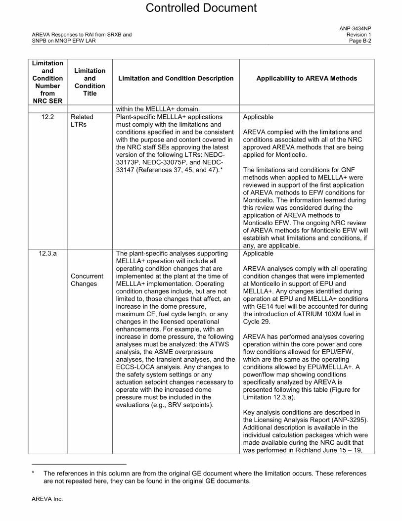
AREVA Responses to RAI from SRXB and SNPB on MNGP EFW LAR
ANP-3434NP Revision 1 Page B-2
Limitation and
Condition Number
from NRC SER
Limitation
and Condition
Title
Limitation and Condition Description
Applicability to AREVA Methods
within the MELLLA+ domain. 12.2 Related
LTRs Plant-specific MELLLA+ applications must comply with the limitations and conditions specified in and be consistent with the purpose and content covered in the NRC staff SEs approving the latest version of the following LTRs: NEDC-33173P, NEDC-33075P, and NEDC-33147 (References 37, 45, and 47).*
Applicable AREVA complied with the limitations and conditions associated with all of the NRC approved AREVA methods that are being applied for Monticello. The limitations and conditions for GNF methods when applied to MELLLA+ were reviewed in support of the first application of AREVA methods to EFW conditions for Monticello. The information learned during this review was considered during the application of AREVA methods to Monticello EFW. The ongoing NRC review of AREVA methods for Monticello EFW will establish what limitations and conditions, if any, are applicable.
12.3.a Concurrent Changes
The plant-specific analyses supporting MELLLA+ operation will include all operating condition changes that are implemented at the plant at the time of MELLLA+ implementation. Operating condition changes include, but are not limited to, those changes that affect, an increase in the dome pressure, maximum CF, fuel cycle length, or any changes in the licensed operational enhancements. For example, with an increase in dome pressure, the following analyses must be analyzed: the ATWS analysis, the ASME overpressure analyses, the transient analyses, and the ECCS-LOCA analysis. Any changes to the safety system settings or any actuation setpoint changes necessary to operate with the increased dome pressure must be included in the evaluations (e.g., SRV setpoints).
Applicable AREVA analyses comply with all operating condition changes that were implemented at Monticello in support of EPU and MELLLA+. Any changes identified during operation at EPU and MELLLA+ conditions with GE14 fuel will be accounted for during the introduction of ATRIUM 10XM fuel in Cycle 29. AREVA has performed analyses covering operation within the core power and core flow conditions allowed for EPU/EFW, which are the same as the operating conditions allowed by EPU/MELLLA+. A power/flow map showing conditions specifically analyzed by AREVA is presented following this table (Figure for Limitation 12.3.a). Key analysis conditions are described in the Licensing Analysis Report (ANP-3295). Additional description is available in the individual calculation packages which were made available during the NRC audit that was performed in Richland June 15 – 19,
* The references in this column are from the original GE document where the limitation occurs. These references are not repeated here, they can be found in the original GE documents.
AREVA Inc.
Controlled Document

AREVA Responses to RAI from SRXB and SNPB on MNGP EFW LAR
ANP-3434NP Revision 1 Page B-3
Limitation and
Condition Number
from NRC SER
Limitation
and Condition
Title
Limitation and Condition Description
Applicability to AREVA Methods
2015. 12.3.b For all topics in LTR NEDC-33006P that
are reduced in scope or generically dispositioned, the plant-specific application will provide justification that the reduced scope or generic disposition is applicable to the plant. If changes that invalidate the LTR dispositions are to be implemented at the time of MELLLA+ implementation, the plant-specific application will provide analyses and evaluations that demonstrate the cumulative effect with MELLLA+ operation. For example, if the dome pressure is increased, the ECCS performance will be evaluated on a plant-specific basis.
Applicable NEDC-33435 describes the application of NEDC-33006 for Monticello. AREVA has analyzed or dispositioned all fuel related events included in the Monticello licensing basis.
12.3.c Any generic bounding sensitivity analyses provided in LTR NEDC-33006P will be evaluated to ensure that the key plant-specific input parameters and assumptions are applicable and bounded. If these generic sensitivity analyses are not applicable or additional operating condition changes affect the generic sensitivity analyses, a plant-specific evaluation will be provided. For example, with an increase in the dome pressure, the ATWS sensitivity analyses that model operator actions (e.g., depressurization if the HCTL is reached) needs to be reanalyzed, using the bounding dome pressure condition.
Applicable See response to 12.3b.
12.3.d If a new GE fuel product line or another vendor’s fuel is loaded at the plant, the applicability of any generic sensitivity analyses supporting the MELLLA+ application shall be justified in the plant-specific application. If the generic sensitivity analyses cannot be demonstrated to be applicable, the analyses will be performed including the new fuel. For example, the ATWS instability analyses supporting the MELLLA+ condition are based on the GE14 fuel response. New analyses that demonstrate the ATWS instability performance of the new GE fuel or another vendor’s fuel for MELLLA+
Applicable AREVA analyses for GE14 and ATRIUM 10XM fuel were reviewed in support of the Monticello fuel transition LAR which was approved by the NRC in June 2015. AREVA analyses for GE14 and ATRIUM 10XM fuel in support of the EFW LAR are currently under NRC review. The AREVA ATWS instability analyses performed in support of the EFW LAR are documented in ANP-3274 and ANP-3284.
AREVA Inc.
Controlled Document

AREVA Responses to RAI from SRXB and SNPB on MNGP EFW LAR
ANP-3434NP Revision 1 Page B-4
Limitation and
Condition Number
from NRC SER
Limitation
and Condition
Title
Limitation and Condition Description
Applicability to AREVA Methods
operation shall be provided to support the plant-specific application.
12.3.e If a new GE fuel product line or another vendor’s fuel is loaded at the plant prior to a MELLLA+ application, the analyses supporting the plant-specific MELLLA+ application will be based on a specific core configuration or bounding core conditions. Any topics that are generically dispositioned or reduced in scope in LTR NEDC-33006P will be demonstrated to be applicable, or new analyses based on the specific core configuration or bounding core conditions will be provided.
See response to 12.3.d.
12.3.f If a new GE fuel product line or another vendor’s fuel is loaded at the plant prior to a MELLLA+ application, the plant-specific application will reference an NRC approved stability method supporting MELLLA+ operation, or provide sufficient plant-specific information to allow the NRC staff to review and approve the stability method supporting MELLLA+ operation. The plant-specific application will demonstrate that the analyses and evaluations supporting the stability method are applicable to the fuel loaded in the core.
See response to 12.3.d.
12.3.g For MELLLA+ operation, core instability is possible in the event a transient or plant maneuver places the reactor at a high power/low-flow condition. Therefore, plants operating at MELLLA+ conditions must have a NRC approved instability protection method. In the event the instability protection method is inoperable, the applicant must employ an NRC-approved backup instability method. The licensee will provide technical specification (TS) changes that specify the instability method operability requirements for MELLLA+ operation, including any backup stability protection methods.
Applicable The AREVA stability methodology is approved for extended power/flow operating domains (ANP-10262PA). Backup stability protection is provided, Section 4.3 of ANP-3295. Section 8.0 of ANP-3295 summarizes the operating limits and COLR input. This licensing report is similar to the GNF SRLR and will be provided to Xcel Energy each cycle.
12.4 The plant-specific MELLLA+ application shall provide the plant-specific thermal limits assessment and transient analysis
Applicable The AREVA thermal limits assessment and
AREVA Inc.
Controlled Document

AREVA Responses to RAI from SRXB and SNPB on MNGP EFW LAR
ANP-3434NP Revision 1 Page B-5
Limitation and
Condition Number
from NRC SER
Limitation
and Condition
Title
Limitation and Condition Description
Applicability to AREVA Methods
results. Considering the timing requirements to support the reload, the fuel and cycle dependent analyses including the plant-specific thermal limits assessment may be submitted by supplementing the initial M+SAR. Additionally, the SRLR for the initial MELLLA+ implementation cycle shall be submitted for NRC staff confirmation.
thermal limits are summarized in Sections 5 and 8 of ANP-3295.
12.5.a Operating Flexibility
The licensee will amend the TS LCO for any equipment out-of-service (i.e., SLO) or operating flexibilities prohibited in the plant-specific MELLLA+ application.
Applicable TS changes are included in the EFW LAR. Xcel Energy is not proposing changes for any equipment out-of-service conditions in support the transition to AREVA fuel and methods.
12.5.b For an operating flexibility, such as FWHOOS, that is prohibited in the MELLLA+ plant-specific application but is not included in the TS LCO, the licensee will propose and implement a license condition.
Applicable Xcel Energy is not proposing changes to operating flexibility in support the transition to AREVA fuel and methods. Refer also to the response to RAI 4.
12.5.c The power flow map is not specified in the TS; however, it is an important licensed operating domain. Licensees may elect to be licensed and operate the plant under plant-specific-expanded domain that is bounded by the MELLLA+ upper boundary. Plant-specific applications approved for operation within the MELLLA+ domain will include the plant-specific power/flow map specifying the licensed domain in the COLR.
Applicable The power flow map is the same for EFW and MELLLA+.
12.6 SLMCPR Statepoints and CF Uncertainty
Until such time when the SLMCPR methodology (References 40 and 41) for off-rated SLMCPR calculation is approved by the staff for MELLLA+ operation, the SLMCPR will be calculated at the rated statepoint (120 percent P/100 percent CF), the plant specific minimum CF statepoint (e.g., 120 percent P/80 percent CF), and at the 100 percent OLTP at 55 percent CF statepoint. The currently approved off-rated CF uncertainty will be used for the minimum CF and 55 percent CF statepoints. The uncertainty must be consistent with the CF uncertainty
Applicable AREVA has performed SLMCPR analyses for the maximum and minimum core flow at rated EPU power, the low core flow MELLLA+ boundary and the maximum core flow achievable during single-loop operation (SLO). In support of the first application of AREVA methods for Monticello EFW, the two-loop operation (TLO) SLMCPR analyses for the minimum core flows at MELLLA+ boundaries were performed using the core flow uncertainties for SLO. The TLO core flow uncertainty was used for SLMCPR analyses at the
AREVA Inc.
Controlled Document

AREVA Responses to RAI from SRXB and SNPB on MNGP EFW LAR
ANP-3434NP Revision 1 Page B-6
Limitation and
Condition Number
from NRC SER
Limitation
and Condition
Title
Limitation and Condition Description
Applicability to AREVA Methods
currently applied to the SLO operation or as NRC-approved for MELLLA+ operation. The calculated values will be documented in the SRLR.
maximum core flow at rated EPU power. The SLO core flow uncertainty was used for the SLO SLMCPR analyses. The SLMCPR values for TLO (1.12) and SLO (1.13) are reported in the Licensing Analysis report (Section 4.2 in ANP-3295). Refer also to responses to RAI 1, RAI 2, RAI 5, RAI 9, RAI 10 and RAI 28.
12.7 Stability Manual operator actions are not adequate to control the consequences of instabilities when operating in the MELLLA+ domain. If the primary stability protection system is declared inoperable, a non-manual NRC approved backup protection system must be provided, or the reactor core must be operated below a NRC approved backup stability boundary specifically approved for MELLLA+ operation for the stability option employed.
Applicable AREVA performed stability analyses in support of the non-manual NRC approved backup protection system. Backup stability protection is described in Section 4.3 of ANP-3295.
12.8 Fluence Methodology and Fracture Toughness
The applicant is to provide a plant-specific evaluation of the MELLLA+ RPV fluence using the most up-to-date NRC-approved fluence methodology. This fluence will then be used to provide a plant-specific evaluation of the RPV fracture toughness in accordance with RG 1.99, Revision 2.
Applicable Xcel Energy methods were used for life time extension and MELLLA+. UO2 starting material type primarily determines the neutron spectrum. Vessel fluence is primarily dependent upon the intensity of neutron spectrum and time. ATRIUM 10XM consists of UO2 starting material that is the same as used in the non-EFW conditions. The intensity of neutron spectrum is dependent upon the core power level which is the same as in the non-EFW conditions. And, the core loading patterns scheme for the non-EFW and EFW operations is the same. Therefore, the operation of ATRIUM 10XM fuel at EFW conditions will not impact the neutron spectrum at the reactor vessel.
12.9 Reactor Coolant Pressure Boundary
MELLLA+ applicants must identify all other than Category “A” materials, as defined in NUREG-0313, Revision 2, that exist in its RCPB piping, and discuss the adequacy of the augmented inspection programs in light of the MELLLA+ operation on a plant-specific basis.
Applicable Addressed by Xcel Energy. Not impacted by the change in fuel type (from GE14 to ATRIUM 10XM) or the fuel vendor (from GNF to AREVA).
12.10.a ECCS- The plant-specific application will provide Applicable
AREVA Inc.
Controlled Document
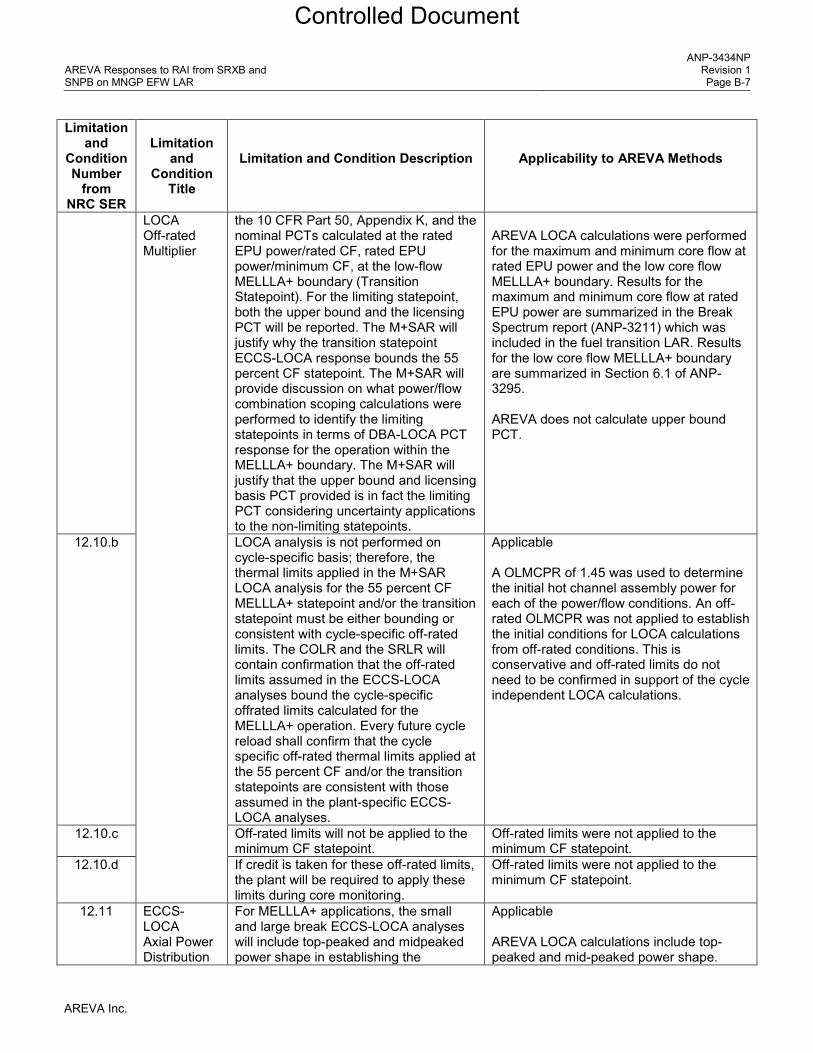
AREVA Responses to RAI from SRXB and SNPB on MNGP EFW LAR
ANP-3434NP Revision 1 Page B-7
Limitation and
Condition Number
from NRC SER
Limitation
and Condition
Title
Limitation and Condition Description
Applicability to AREVA Methods
LOCA Off-rated Multiplier
the 10 CFR Part 50, Appendix K, and the nominal PCTs calculated at the rated EPU power/rated CF, rated EPU power/minimum CF, at the low-flow MELLLA+ boundary (Transition Statepoint). For the limiting statepoint, both the upper bound and the licensing PCT will be reported. The M+SAR will justify why the transition statepoint ECCS-LOCA response bounds the 55 percent CF statepoint. The M+SAR will provide discussion on what power/flow combination scoping calculations were performed to identify the limiting statepoints in terms of DBA-LOCA PCT response for the operation within the MELLLA+ boundary. The M+SAR will justify that the upper bound and licensing basis PCT provided is in fact the limiting PCT considering uncertainty applications to the non-limiting statepoints.
AREVA LOCA calculations were performed for the maximum and minimum core flow at rated EPU power and the low core flow MELLLA+ boundary. Results for the maximum and minimum core flow at rated EPU power are summarized in the Break Spectrum report (ANP-3211) which was included in the fuel transition LAR. Results for the low core flow MELLLA+ boundary are summarized in Section 6.1 of ANP-3295. AREVA does not calculate upper bound PCT.
12.10.b LOCA analysis is not performed on cycle-specific basis; therefore, the thermal limits applied in the M+SAR LOCA analysis for the 55 percent CF MELLLA+ statepoint and/or the transition statepoint must be either bounding or consistent with cycle-specific off-rated limits. The COLR and the SRLR will contain confirmation that the off-rated limits assumed in the ECCS-LOCA analyses bound the cycle-specific offrated limits calculated for the MELLLA+ operation. Every future cycle reload shall confirm that the cycle specific off-rated thermal limits applied at the 55 percent CF and/or the transition statepoints are consistent with those assumed in the plant-specific ECCS-LOCA analyses.
Applicable A OLMCPR of 1.45 was used to determine the initial hot channel assembly power for each of the power/flow conditions. An off-rated OLMCPR was not applied to establish the initial conditions for LOCA calculations from off-rated conditions. This is conservative and off-rated limits do not need to be confirmed in support of the cycle independent LOCA calculations.
12.10.c Off-rated limits will not be applied to the minimum CF statepoint.
Off-rated limits were not applied to the minimum CF statepoint.
12.10.d If credit is taken for these off-rated limits, the plant will be required to apply these limits during core monitoring.
Off-rated limits were not applied to the minimum CF statepoint.
12.11 ECCS-LOCA Axial Power Distribution
For MELLLA+ applications, the small and large break ECCS-LOCA analyses will include top-peaked and midpeaked power shape in establishing the
Applicable AREVA LOCA calculations include top-peaked and mid-peaked power shape.
AREVA Inc.
Controlled Document

AREVA Responses to RAI from SRXB and SNPB on MNGP EFW LAR
ANP-3434NP Revision 1 Page B-8
Limitation and
Condition Number
from NRC SER
Limitation
and Condition
Title
Limitation and Condition Description
Applicability to AREVA Methods
Evaluation MAPLHGR and determining the PCT. This limitation is applicable to both the licensing bases PCT and the upper bound PCT. The plant-specific applications will report the limiting small and large break licensing basis and upper bound PCTs.
AREVA does not calculate upper bound PCT. AREVA calculated large and small break PCTs. Results for the low core flow MELLLA+ boundary are summarized in Section 6.1 of ANP-3295.
12.12.a ECCS-LOCA Reporting
Both the nominal and Appendix K PCTs should be reported for all of the calculated statepoints, and The plant-variable and uncertainties currently applied will be used, unless the NRC staff specifically approves a different plant variable uncertainty method for application to the non-rated statepoints.
AREVA only calculates and reports Appendix K PCTs.
12.12.b The plant-variable and uncertainties currently applied will be used, unless the NRC staff specifically approves a different plant variable uncertainty method for application to the non-rated statepoints.
AREVA only calculates and reports Appendix K PCTs.
12.13 Small Break LOCA
Small break LOCA analysis will be performed at the MELLLA+ minimum CF and the transition statepoints for those plants that: (1) are small break LOCA limited based on small break LOCA analysis performed at the rated EPU conditions; or (2) have margins of less than or equal to [ ] relative to the Appendix K or the licensing basis PCT.
Applicable Small break analyses are being performed for the maximum and minimum core flow at rated EPU power and the low core flow MELLLA+ boundary. The transition statepoint refers to the flow along the MELLLA+ boundary where the MAPLHGR multiplier becomes less than 1.0. A MAPLHGR multiplier can be established to protect the acceptance criteria for a LOCA initiated from low core flow or low core power. Based on the AREVA LOCA results, full MAPLHGR limit is supported at the low core flow MELLLA+ boundary.
12.14 Break Spectrum
The scope of small break LOCA analysis for MELLLA+ operation relies upon the EPU small break LOCA analysis results. Therefore, the NRC staff concludes that for plants that will implement MELLLA+, sufficient small break sizes should be analyzed at the rated EPU power level to ensure that the peak PCT break size is
Applicable AREVA performed sufficient small break analyses to assure the limiting break size has been identified. The results for EFW are summarized in Section 6.1 of ANP-3295. The results for the maximum and minimum core flow at rated EPU power
AREVA Inc.
Controlled Document

AREVA Responses to RAI from SRXB and SNPB on MNGP EFW LAR
ANP-3434NP Revision 1 Page B-9
Limitation and
Condition Number
from NRC SER
Limitation
and Condition
Title
Limitation and Condition Description
Applicability to AREVA Methods
identified. were reported in ANP-3211, which the NRC reviewed as part of the fuel transition LAR. Responses to fuel transition RAI about small breaks were provided in ANP-3286.
12.15 Bypass Voiding Above the D- level
Plant-specific MELLLA+ applications shall identify where in the MELLLA+ upper boundary the bypass voiding greater than 5 percent will occur above the D-level. The licensee shall provide in the plant-specific submittal the operator actions and procedures that will mitigate the impact of the bypass voiding on the TIPs and the core simulator used to monitor the fuel performance. The plant-specific submittal shall also provide discussion on what impact the bypass voiding greater than 5 percent will have on the NMS as defined in Section 5.1.1.5. The NRC staff will evaluate on plant-specific bases acceptability of bypass voiding above D level.
Applicable Bypass voiding was addressed in the report which addresses the applicability of AREVA methods to EPU and MELLLA+ (ANP-3135P). Additional information about bypass voiding is provided in ANP-3224 (Reference B1), which was reviewed and approved in support of the fuel transition LAR.
12.16 RWE Plants operating at the MELLLA+ operating domain shall perform RWE analyses to confirm the adequacy of the generic RBM setpoints. The M+SAR shall provide a discussion of the analyses performed and the results.
Applicable AREVA performed RWE analyses and the results are summarized in the Licensing Analysis Report (Section 5.1.7 in ANP-3295).
12.17 ATWS LOOP
As specified in LTR NEDC-33006P, at least two plant specific ATWS calculations must be performed: MSIVC and PRFO. In addition, if RHR capability is affected by LOOP, then a third plant-specific ATWS calculation must be performed that includes the reduced RHR capability. To evaluate the effect of reduced RHR capacity during LOOP, the plant-specific ATWS calculation must be performed for a sufficiently large period of time after HSBW injection is complete to guarantee that the suppression pool temperature is cooling, indicating that the RHR capacity is greater than the decay heat generation. The plant-specific application should include evaluation of the safety system performance during the long-term cooling phase, in terms of available NPSH.
Applicable AREVA calculated peak vessel pressure with the COTRANSA2 code since it occurs early in the event. The results are summarized in the Licensing Analysis Report (Section 7.2.1 in ANP-3295). The impact of changing from GE14 to ATRIUM 10XM on long term ATWS criteria is addressed in Section 7.2.2 of ANP-3295. Additional information has been provided in response to RAI from the Containment and Ventilation branch, Reference B2. The MNGP analysis of record remains conservatively applicable for ATRIUM 10XM fuel operating within EFW.
AREVA Inc.
Controlled Document

AREVA Responses to RAI from SRXB and SNPB on MNGP EFW LAR
ANP-3434NP Revision 1 Page B-10
Limitation and
Condition Number
from NRC SER
Limitation
and Condition
Title
Limitation and Condition Description
Applicability to AREVA Methods
12.18.a ATWS TRACG Analysis
For plants that do not achieve hot shutdown prior to reaching the heat capacity temperature limit (HCTL) based on the licensing ODYN code calculation, plant specific MELLLA+ implementations must perform best estimate TRACG calculations on a plant-specific basis. The TRACG analysis will account for all plant parameters, including water-level control strategy and all plant-specific emergency operating procedure (EOP) actions.
Applicable See response to 12.17.
12.18.b The TRACG calculation is not required if the plant increases the boron-10 concentration/enrichment so that the integrated heat load to containment calculated by the licensing ODYN calculation does not change with respect to a reference OLTP/75 percent flow ODYN calculation.
Applicable See response to 12.17.
12.18.c Peak cladding temperature (PCT) for both phases of the transient (initial overpressure and emergency depressurization) must be evaluated on a plant-specific basis with the TRACG ATWS calculation.
Applicable See response to 12.17.
12.18.d In general, the plant-specific application will ensure that operation in the MELLLA+ domain is consistent with the assumptions used in the ATWS analysis, including equipment out of service (e.g., FWHOOS, SLO, SRVs, SLC pumps, and RHR pumps, etc.). If assumptions are not satisfied, operation in MELLLA+ is not allowed. The SRLR will specify the prohibited flexibility options for plant-specific MELLLA+ operation, where applicable. For key input parameters, systems and engineering safety features that are important to simulating the ATWS analysis and are specified in the Technical Specification (TS) (e.g., SLCS parameters, ATWS RPT, etc.), the calculation assumptions must be consistent with the allowed TS values and the allowed plant configuration. If the analyses deviate from the allowed TS configuration for long term equipment out of service (i.e., beyond the TS LCO), the
Applicable See response to 12.17.
AREVA Inc.
Controlled Document

AREVA Responses to RAI from SRXB and SNPB on MNGP EFW LAR
ANP-3434NP Revision 1 Page B-11
Limitation and
Condition Number
from NRC SER
Limitation
and Condition
Title
Limitation and Condition Description
Applicability to AREVA Methods
plant-specific application will specify and justify the deviation. In addition, the licensee must ensure that all operability requirements are met (e.g., NPSH) by equipment assumed operable in the calculations.
12.18.e Nominal input parameters can be used in the ATWS analyses provided the uncertainty treatment and selection of the values of these input parameters are consistent with the input methods used in the original GE ATWS analyses in NEDE-24222. Treatment of key input parameters in terms of uncertainties applied or plant-specific TS value used can differ from the original NEDE-24222 approach, provided the manner in which it is used yields more conservative ATWS results.
Applicable AREVA reviewed the GE Task Reports for ATWS to understand the Monticello Analysis of Record. The input parameters are best estimate with reasonable bounding conditions. The AREVA calculation of peak vessel pressure used the same or more conservative input parameters used in the GEH ATWS peak pressure calculation for Monticello. The AREVA ATWS analysis results and evaluations are summarized in Section 7.2 of ANP-3295 and additional information has been provided in response to RAI from the Containment and Ventilation branch, Reference B2.
12.18.f The plant-specific application will include tabulation and discussion of the key input parameters and the associated uncertainty treatment.
Applicable See response to 12.18e.
12.19 Plant-Specific ATWS Instability
Until such time that NRC approves a generic solution for ATWS instability calculations for MELLLA+ operation, each plant-specific MELLLA+ application must provide ATWS instability analysis that satisfies the ATWS acceptance criteria listed in SRP Section 15.8. The plant-specific ATWS instability calculation must: (1) be based on the peak-reactivity exposure conditions, (2) model the plant-specific configuration important to ATWS instability response including mixed core, if applicable, and (3) use the regional-mode nodalization scheme. In order to improve the fidelity of the analyses, the plant-specific calculations should be based on latest NRC-approved neutronic and thermal-hydraulic codes such as GBLA06/PANAC11 and TRACG04.
Applicable AREVA performed ATWS instability analyses that are summarized in the EFW LAR (ANP-3274 and ANP-3284).
AREVA Inc.
Controlled Document

AREVA Responses to RAI from SRXB and SNPB on MNGP EFW LAR
ANP-3434NP Revision 1 Page B-12
Limitation and
Condition Number
from NRC SER
Limitation
and Condition
Title
Limitation and Condition Description
Applicability to AREVA Methods
12.20 Generic ATWS Instability
Once the generic solution is approved, the plant-specific applications must provide confirmation that the generic instability analyses are relevant and applicable to their plant. Applicability confirmation includes review of any differences in plant design or operation that will result in significantly lower stability margins during ATWS such as: • turbine bypass capacity, • fraction of steam-driven feedwater pumps, • any changes in plant design or operation that will significantly increase core inlet subcooling during ATWS events, • significant differences in radial and axial power distributions, • hot-channel power-to-flow ratio, • fuel design changes beyond GE14.
Applicable AREVA has performed a plant specific analysis for Monticello. See response to 12.19.
12.21 Individual Plant Evaluation
Licensees that submit a MELLLA+ application should address the plant-specific risk impacts associated with MELLLA+ implementation, consistent with approved guidance documents (e.g., NEDC-32424P-A, NEDC-32523P-A, and NEDC-33004P-A) and the Matrix 13 of RS-001 and re-address the plant-specific risk impacts consistent with the approved guidance documents that were used in their approved EPU application and Matrix 13 of RS-001. If an EPU and MELLLA+ application come to the NRC in parallel, the expectation is that the EPU submittal will have incorporated the MELLLA+ impacts.
Applicable Changing the fuel type (from GE14 to ATRIUM 10XM) or the fuel vendor (from GNF to AREVA) does not impact the risks associated with Monticello operation in MELLLA+ / EFW conditions.
12.22 IASCC The applicant is to provide a plant-specific IASCC evaluation when implementing MELLLA+, which includes the components that will exceed the IASCC threshold of 5x10²⁰ n/cm2 (E>1MeV), the impact of failure of these components on the integrity of the reactor internals and core support structures under licensing design bases conditions, and the inspections that will be performed on components that exceed the IASCC threshold to ensure timely identification of IASCC, should it occur.
M+SAR Section 10.7.1 Not impacted by the change in fuel type or fuel vendor. See response to 12.8.
AREVA Inc.
Controlled Document

AREVA Responses to RAI from SRXB and SNPB on MNGP EFW LAR
ANP-3434NP Revision 1 Page B-13
Limitation and
Condition Number
from NRC SER
Limitation
and Condition
Title
Limitation and Condition Description
Applicability to AREVA Methods
12.23.1 Limitations from the ATWS RAI Evaluations
See limitation 12.18.d Not applicable to Monticello 12.23.2 The plant-specific ODYN and TRACG
key calculation parameters must be provided to the staff so they can verify that all plant-specific automatic settings are modeled properly.
Applicable AREVA has performed plant specific analyses for Monticello. These analyses were made available during the NRC audit that was performed in Richland June 15 – 19, 2015.
12.23.3 The ATWS peak pressure response would be dependent upon SRVs upper tolerances assumed in the calculations. For each individual SRV, the tolerances used in the analysis must be consistent with or bound the plant-specific SRV performance. The SRV tolerance test data would be statistically treated using the NRC’s historical 95/95 approach or any new NRC-approved statistical treatment method. In the event that current EPU experience base shows propensity for valve drift higher than pre-EPU experience base, the plant-specific transient and ATWS analyses would be based on the higher tolerances or justify the reason why the propensity for the higher drift is not applicable the plant’s SRVs.
Applicable See response to 12.18.e.
12.23.4 EPG/SAG parameters must be reviewed for applicability to MELLLA+ operation in a plant-specific basis. The plant-specific MELLLA+ application will include a section that discusses the plant-specific EOPs and confirms that the ATWS calculation is consistent with the operator actions.
Applicable AREVA has calculated the cycle-independent ATRIUM 10XM fuel data to be used by Xcel Energy in EPG/SAG calculations.
12.23.5 The conclusions of this LTR and associated SE are limited to reactors operating with a power density lower than 52.5 MW/MLBM/hr for operation at the minimum allowable CF at 120 percent OLTP. Verification that reactor operation will be maintained below this analysis limit must be performed for all plant-specific applications.
Applicable Monticello power density meets the stated limitation. Not impacted by the change in fuel type or fuel vendor.
12.23.6 For MELLLA+ applications involving GE fuel types beyond GE14 or other vendor fuels, bounding ATWS Instability analysis will be provided to the staff. Note: this limitation does not apply to
Applicable AREVA performed ATWS instability analyses that are summarized in the EFW LAR (ANP-3274 and ANP-3284).
AREVA Inc.
Controlled Document

AREVA Responses to RAI from SRXB and SNPB on MNGP EFW LAR
ANP-3434NP Revision 1 Page B-14
Limitation and
Condition Number
from NRC SER
Limitation
and Condition
Title
Limitation and Condition Description
Applicability to AREVA Methods
special test assemblies. 12.23.7 See limitation 12.23.6 12.23.8 The plant-specific ATWS calculations
must account for all plant- and fuel-design-specific features, such as the debris filters.
Applicable The AREVA calculations for ATWS peak vessel pressure and ATWS Instability accounted for all plant- and fuel-design-specific features, such as the debris filters.
12.23.9 Plant-specific applications must review the safety system specifications to ensure that all of the assumptions used for the ATWS SE indeed apply to their plant-specific conditions. The NRC staff review will give special attention to crucial safety systems like HPCI, and physical limitations like NPSH and maximum vessel pressure that RCIC and HPCI can inject. The plant-specific application will include a discussion on the licensing bases of the plant in terms of NPSH and system performance. It will also include NPSH and system performance evaluation for the duration of the event.
Applicable See response to 12.18.e.
12.23.10 Plant-specific applications must ensure that an increase in containment pressure resulting from ATWS events with EPU/MELLLA+ operation does not affect adversely the operation of safety-grade equipment.
Applicable See response to 12.17.
12.23.11 The plant-specific applications must justify the use of plant-specific suppression pool temperature limits for the ODYN and TRACG calculations that are higher than the HCTL limit for emergency depressurization.
Applicable See response to 12.17.
12.24.1 Limitations from Fuel Dependent Analyses RAI Evaluations
For EPU/MELLLA+ plant-specific applications that use TRACG or any code that has the capability to model inchannel water rod flow, the supporting analysis will use the actual flow configuration.
Applicable The inchannel water rod (GE14) or water channel (ATRIUM XM) flow will be modeled in AREVA codes. The modeling will be explicit or implicit depending on the capability and application of the code, refer to table which follows (Table for Limitation 12.24.1).
12.24.2 The EPU/MELLLA+ application would provide the exit void fraction of the high-powered bundles in the comparison between the EPU/MELLLA+ and the
Applicable The maximum exit void fraction of the high-powered bundles for EPU/EFW operation is
AREVA Inc.
Controlled Document

AREVA Responses to RAI from SRXB and SNPB on MNGP EFW LAR
ANP-3434NP Revision 1 Page B-15
Limitation and
Condition Number
from NRC SER
Limitation
and Condition
Title
Limitation and Condition Description
Applicability to AREVA Methods
pre-MELLLA+ conditions. presented in Figure A-36 of ANP-3224P. 12.24.3 See limitation 12.6 See limitation 12.6. 12.24.4 See limitation 12.18.d See limitation 12.18.d.
References for Appendix B
B1. ANP-3224P Revision 2, Applicability of AREVA NP BWR Methods to Monticello, June 2013. (transmitted to NRC as part of the fuel transition LAR)
B2. ANP-3424P Revision 1, AREVA Responses to RAI from SCVB on MNGP EFW LAR, August 2015.
AREVA Inc.
Controlled Document
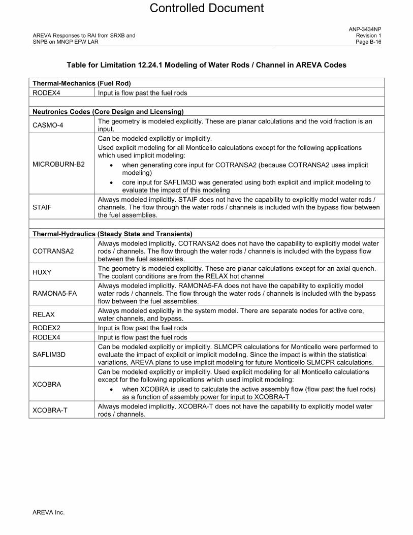
AREVA Responses to RAI from SRXB and SNPB on MNGP EFW LAR
ANP-3434NP Revision 1 Page B-16
Table for Limitation 12.24.1 Modeling of Water Rods / Channel in AREVA Codes
Thermal-Mechanics (Fuel Rod) RODEX4 Input is flow past the fuel rods Neutronics Codes (Core Design and Licensing)
CASMO-4 The geometry is modeled explicitly. These are planar calculations and the void fraction is an input.
MICROBURN-B2
Can be modeled explicitly or implicitly. Used explicit modeling for all Monticello calculations except for the following applications which used implicit modeling:
• when generating core input for COTRANSA2 (because COTRANSA2 uses implicit modeling)
• core input for SAFLIM3D was generated using both explicit and implicit modeling to evaluate the impact of this modeling
STAIF Always modeled implicitly. STAIF does not have the capability to explicitly model water rods / channels. The flow through the water rods / channels is included with the bypass flow between the fuel assemblies.
Thermal-Hydraulics (Steady State and Transients)
COTRANSA2 Always modeled implicitly. COTRANSA2 does not have the capability to explicitly model water rods / channels. The flow through the water rods / channels is included with the bypass flow between the fuel assemblies.
HUXY The geometry is modeled explicitly. These are planar calculations except for an axial quench. The coolant conditions are from the RELAX hot channel
RAMONA5-FA Always modeled implicitly. RAMONA5-FA does not have the capability to explicitly model water rods / channels. The flow through the water rods / channels is included with the bypass flow between the fuel assemblies.
RELAX Always modeled explicitly in the system model. There are separate nodes for active core, water channels, and bypass.
RODEX2 Input is flow past the fuel rods RODEX4 Input is flow past the fuel rods
SAFLIM3D Can be modeled explicitly or implicitly. SLMCPR calculations for Monticello were performed to evaluate the impact of explicit or implicit modeling. Since the impact is within the statistical variations, AREVA plans to use implicit modeling for future Monticello SLMCPR calculations.
XCOBRA
Can be modeled explicitly or implicitly. Used explicit modeling for all Monticello calculations except for the following applications which used implicit modeling:
• when XCOBRA is used to calculate the active assembly flow (flow past the fuel rods) as a function of assembly power for input to XCOBRA-T
XCOBRA-T Always modeled implicitly. XCOBRA-T does not have the capability to explicitly model water rods / channels.
AREVA Inc.
Controlled Document

AREVA Responses to RAI from SRXB and SNPB on MNGP EFW LAR
ANP-3434NP Revision 1 Page B-17
Figure for Limitation 12.3a Power/Flow Conditions Where AREVA Performed Transient Analyses
NOTE: Red power/flow points were analyzed in support of EFW. Some transients were only analyzed at a subset of these power/flow points. Green power/flow points were added to support the pre-EFW fuel transition LAR.
AREVA Inc.
Controlled Document
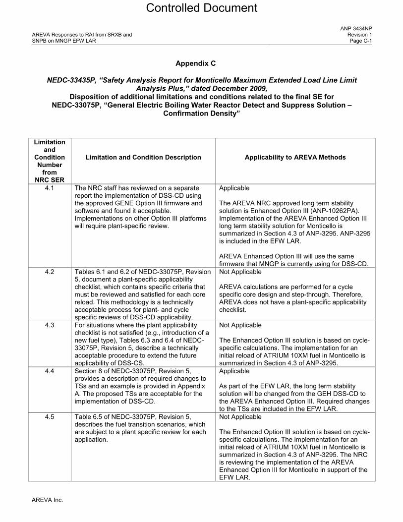
AREVA Responses to RAI from SRXB and SNPB on MNGP EFW LAR
ANP-3434NP Revision 1 Page C-1
Appendix C
NEDC-33435P, “Safety Analysis Report for Monticello Maximum Extended Load Line Limit Analysis Plus,” dated December 2009,
Disposition of additional limitations and conditions related to the final SE for NEDC-33075P, “General Electric Boiling Water Reactor Detect and Suppress Solution –
Confirmation Density”
Limitation and
Condition Number
from NRC SER
Limitation and Condition Description
Applicability to AREVA Methods
4.1 The NRC staff has reviewed on a separate report the implementation of DSS-CD using the approved GENE Option III firmware and software and found it acceptable. Implementations on other Option III platforms will require plant-specific review.
Applicable The AREVA NRC approved long term stability solution is Enhanced Option III (ANP-10262PA). Implementation of the AREVA Enhanced Option III long term stability solution for Monticello is summarized in Section 4.3 of ANP-3295. ANP-3295 is included in the EFW LAR. AREVA Enhanced Option III will use the same firmware that MNGP is currently using for DSS-CD.
4.2 Tables 6.1 and 6.2 of NEDC-33075P, Revision 5, document a plant-specific applicability checklist, which contains specific criteria that must be reviewed and satisfied for each core reload. This methodology is a technically acceptable process for plant- and cycle specific reviews of DSS-CD applicability.
Not Applicable AREVA calculations are performed for a cycle specific core design and step-through. Therefore, AREVA does not have a plant-specific applicability checklist.
4.3 For situations where the plant applicability checklist is not satisfied (e.g., introduction of a new fuel type), Tables 6.3 and 6.4 of NEDC-33075P, Revision 5, describe a technically acceptable procedure to extend the future applicability of DSS-CS.
Not Applicable The Enhanced Option III solution is based on cycle-specific calculations. The implementation for an initial reload of ATRIUM 10XM fuel in Monticello is summarized in Section 4.3 of ANP-3295.
4.4 Section 8 of NEDC-33075P, Revision 5, provides a description of required changes to TSs and an example is provided in Appendix A. The proposed TSs are acceptable for the implementation of DSS-CD.
Applicable As part of the EFW LAR, the long term stability solution will be changed from the GEH DSS-CD to the AREVA Enhanced Option III. Required changes to the TSs are included in the EFW LAR.
4.5 Table 6.5 of NEDC-33075P, Revision 5, describes the fuel transition scenarios, which are subject to a plant specific review for each application.
Not Applicable The Enhanced Option III solution is based on cycle-specific calculations. The implementation for an initial reload of ATRIUM 10XM fuel in Monticello is summarized in Section 4.3 of ANP-3295. The NRC is reviewing the implementation of the AREVA Enhanced Option III for Monticello in support of the EFW LAR.
AREVA Inc.
Controlled Document

AREVA Responses to RAI from SRXB and SNPB on MNGP EFW LAR
ANP-3434NP Revision 1 Page C-2
Limitation and
Condition Number
from NRC SER
Limitation and Condition Description
Applicability to AREVA Methods
4.6 Application of an alternative to the generic CDA setpoints with respect to the susceptibility of a plant’s intrinsic noise will require a plant-specific review.
Not Applicable See response to 4.5.
4.7 The hardware components required to implement DSSCD are expected to be those currently used for the approved Solution III. If the DSS-CD hardware implementation deviates significantly from the approved Solution III, a hardware review by the NRC staff may be necessary.
Applicable The hardware components for DSS-CD are currently installed at MNGP in support of MELLLA+. AREVA Enhanced Option III will use the same hardware that MNGP is currently using for DSS-CD. The implementation of Enhanced Option III solution on the MNGP hardware is discussed in the EFW LAR.
4.8 The NRC staff concludes that the plant-specific settings for eight of the FIXED parameters and three of the ADJUSTABLE parameters appear to be licensing basis values. The process by which these values will be controlled must be addressed by licensees.
Not Applicable See response to 4.5.
4.9 The NRC staff concludes that if plants other than Brunswick Steam Electric Plant, Units 1 and 2, use the DSS-CD trip function, those plant licensees must ensure the DSS-CD trip function is applicable in their plant licensing bases, including the optional BSP trip function, if it is to be installed.
See response to 4.5.
AREVA Inc.
Controlled Document

AREVA Responses to RAI from SRXB and SNPB on MNGP EFW LAR
ANP-3434NP Revision 1 Page D-1
Appendix D
NEDC-33435P, “Safety Analysis Report for Monticello Maximum Extended Load Line Limit Analysis Plus,” dated December 2009,
Disposition of additional limitations and conditions related to the final SE for NEDC-33147P, "DSS-CD TRACG Application"
Limitation
and Condition Number
from NRC SER
Limitation and Condition Description
Applicability to AREVA Methods
4.1 The NRC staff will require a submittal for review if any significant change in the bounding uncertainty or any change in the process to bound the uncertainty in the MCPR is proposed.
Not Applicable This condition is for TRACG and DSS-CD. There is no change in the calculation process from the approved Enhanced Option III solution (ANP-10262PA).
AREVA Inc.
Controlled Document

AREVA Responses to RAI from SRXB and SNPB on MNGP EFW LAR
ANP-3434NP Revision 1 Page E-1
Appendix E
Effect of solid wall material in quench correlations [
]
AREVA Inc.
Controlled Document

AREVA Responses to RAI from SRXB and SNPB on MNGP EFW LAR
ANP-3434NP Revision 1 Page E-2
[
]
AREVA Inc.
Controlled Document

AREVA Responses to RAI from SRXB and SNPB on MNGP EFW LAR
ANP-3434NP Revision 1 Page E-3
[
]
AREVA Inc.
Controlled Document