engineering instrumentation - fundamentals analysis web/engineering... · 1 engineering...
TRANSCRIPT
V. Rouillard 2003Engineering Instrumentation - Fundamentals1
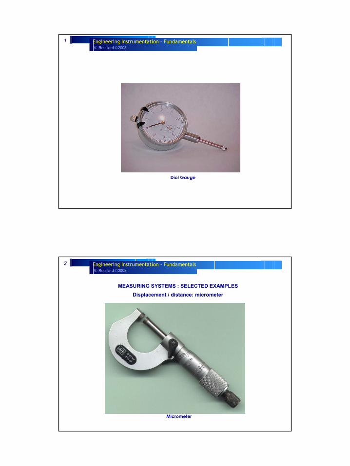
Dial Gauge
V. Rouillard 2003Engineering Instrumentation - Fundamentals2
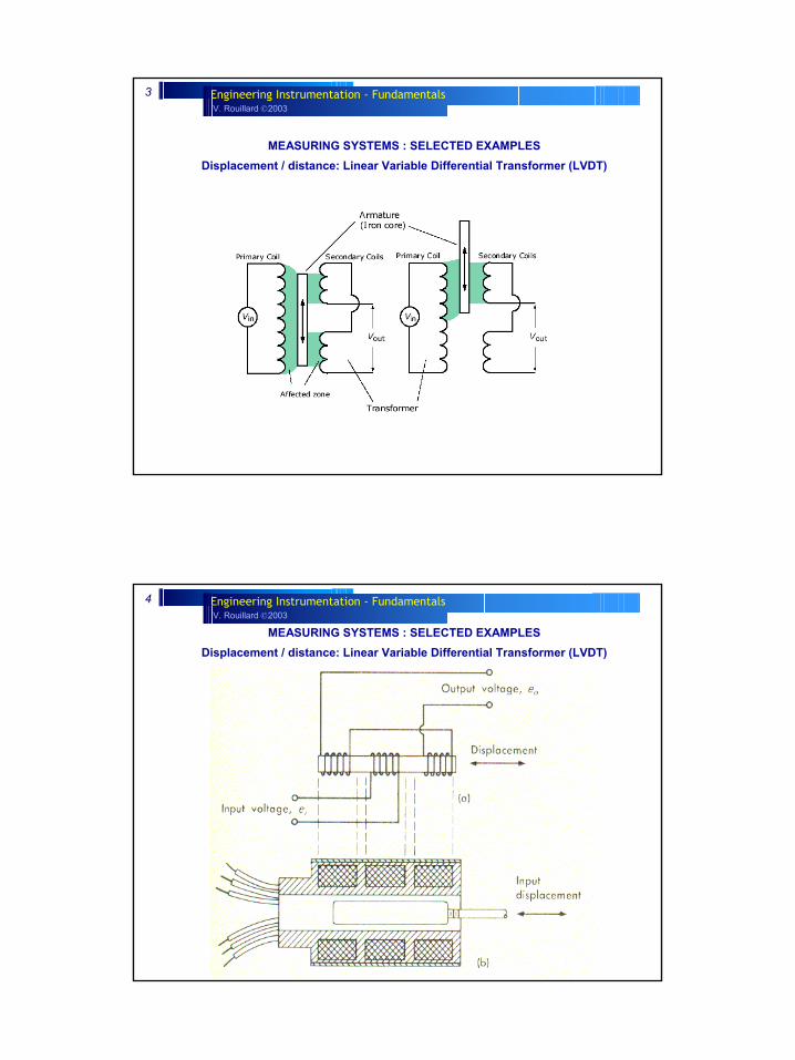
MEASURING SYSTEMS : SELECTED EXAMPLES Displacement / distance: micrometer
Micrometer
V. Rouillard 2003Engineering Instrumentation - Fundamentals3
MEASURING SYSTEMS : SELECTED EXAMPLES Displacement / distance: Linear Variable Differential Transformer (LVDT)
V. Rouillard 2003Engineering Instrumentation - Fundamentals4
MEASURING SYSTEMS : SELECTED EXAMPLES Displacement / distance: Linear Variable Differential Transformer (LVDT)
V. Rouillard 2003Engineering Instrumentation - Fundamentals5
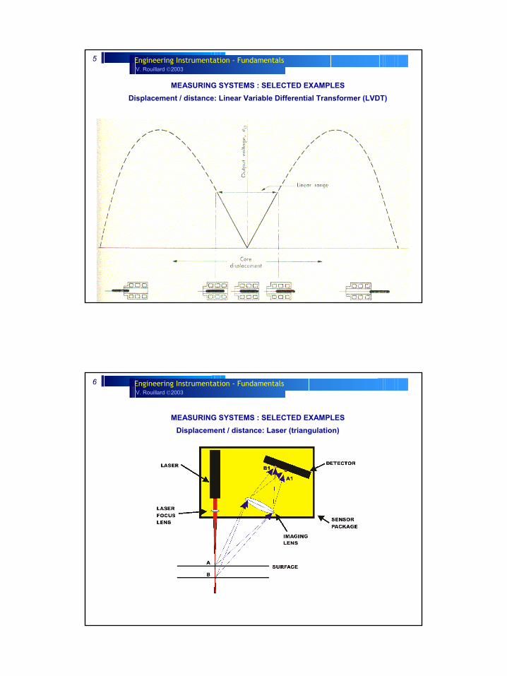
MEASURING SYSTEMS : SELECTED EXAMPLES Displacement / distance: Linear Variable Differential Transformer (LVDT)
V. Rouillard 2003Engineering Instrumentation - Fundamentals6
MEASURING SYSTEMS : SELECTED EXAMPLES Displacement / distance: Laser (triangulation)
V. Rouillard 2003Engineering Instrumentation - Fundamentals7
MEASURING SYSTEMS : SELECTED EXAMPLES Displacement / distance: Laser (triangulation)
V. Rouillard 2003Engineering Instrumentation - Fundamentals8
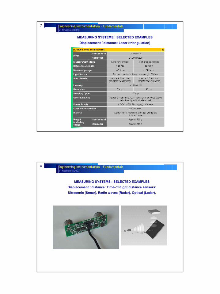
MEASURING SYSTEMS : SELECTED EXAMPLES Displacement / distance: Time-of-flight distance sensors:Ultrasonic (Sonar), Radio waves (Radar), Optical (Ladar),
V. Rouillard 2003Engineering Instrumentation - Fundamentals9
MEASURING SYSTEMS : SELECTED EXAMPLES Displacement / distance: Time-of-flight distance sensors:Ultrasonic (Sonar), Radio waves (Radar), Optical (Ladar),
V. Rouillard 2003Engineering Instrumentation - Fundamentals10
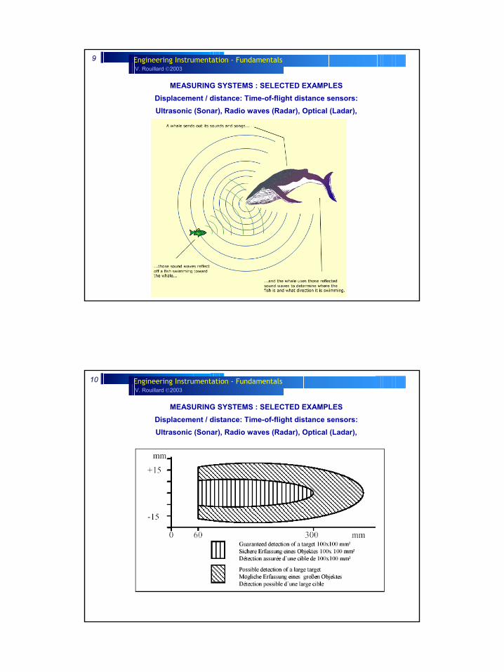
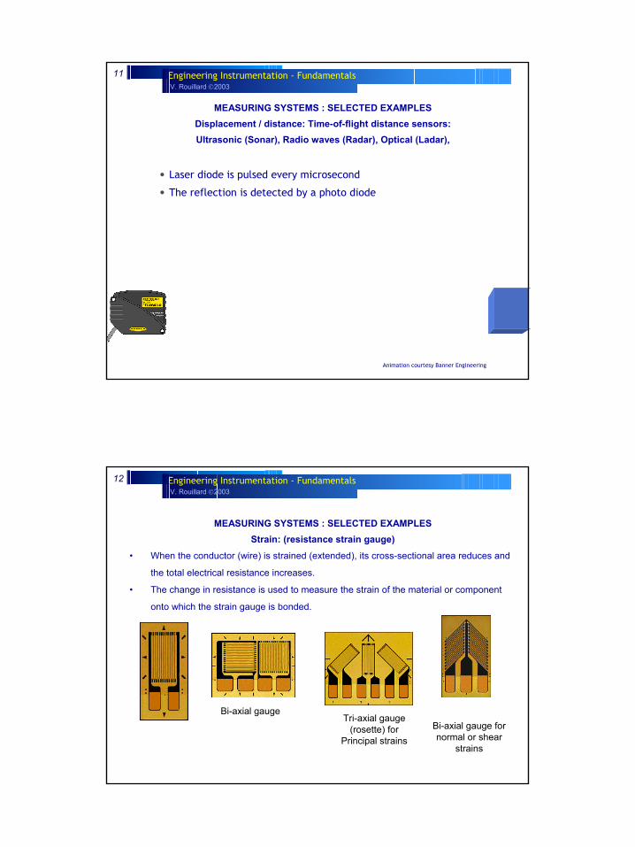
MEASURING SYSTEMS : SELECTED EXAMPLES Displacement / distance: Time-of-flight distance sensors:Ultrasonic (Sonar), Radio waves (Radar), Optical (Ladar),
V. Rouillard 2003Engineering Instrumentation - Fundamentals11
MEASURING SYSTEMS : SELECTED EXAMPLES Displacement / distance: Time-of-flight distance sensors:Ultrasonic (Sonar), Radio waves (Radar), Optical (Ladar),
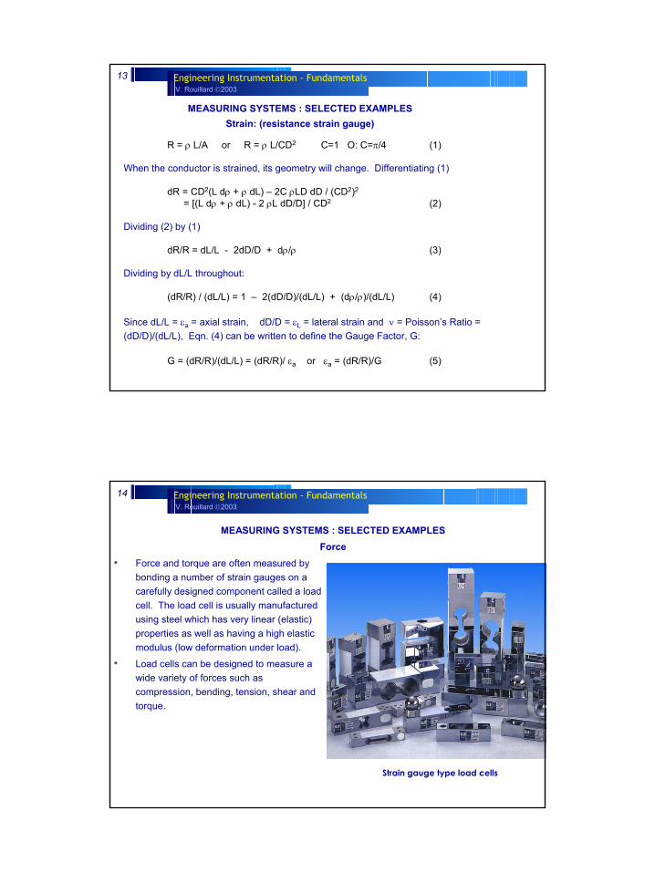
• Laser diode is pulsed every microsecond
• The reflection is detected by a photo diode
Animation courtesy Banner Engineering
V. Rouillard 2003Engineering Instrumentation - Fundamentals12
MEASURING SYSTEMS : SELECTED EXAMPLES Strain: (resistance strain gauge)
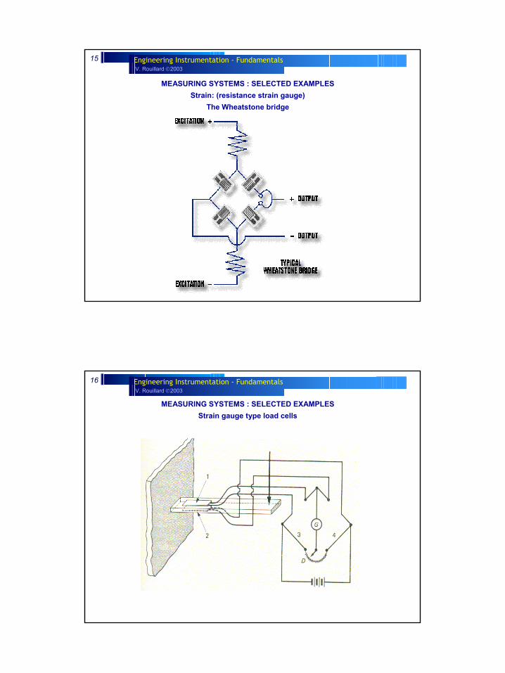
• When the conductor (wire) is strained (extended), its cross-sectional area reduces and
the total electrical resistance increases.
• The change in resistance is used to measure the strain of the material or component
onto which the strain gauge is bonded.
Bi-axial gaugeTri-axial gauge
(rosette) for Principal strains
Bi-axial gauge for normal or shear
strains
V. Rouillard 2003Engineering Instrumentation - Fundamentals13
R = ρ L/A or R = ρ L/CD2 � C=1 O: C=π/4 (1)
When the conductor is strained, its geometry will change. Differentiating (1)
dR = CD2(L dρ + ρ dL) – 2C ρLD dD / (CD2)2
= [(L dρ + ρ dL) - 2 ρL dD/D] / CD2 (2)
Dividing (2) by (1)
dR/R = dL/L - 2dD/D + dρ/ρ (3)
Dividing by dL/L throughout:
(dR/R) / (dL/L) = 1 – 2(dD/D)/(dL/L) + (dρ/ρ)/(dL/L) (4)
Since dL/L = εa = axial strain, dD/D = εL = lateral strain and ν = Poisson’s Ratio = (dD/D)/(dL/L), Eqn. (4) can be written to define the Gauge Factor, G:
G = (dR/R)/(dL/L) = (dR/R)/ εa or εa = (dR/R)/G (5)
MEASURING SYSTEMS : SELECTED EXAMPLES Strain: (resistance strain gauge)
V. Rouillard 2003Engineering Instrumentation - Fundamentals14
MEASURING SYSTEMS : SELECTED EXAMPLES Force
Strain gauge type load cells
• Force and torque are often measured by bonding a number of strain gauges on a carefully designed component called a load cell. The load cell is usually manufactured using steel which has very linear (elastic) properties as well as having a high elastic modulus (low deformation under load).
• Load cells can be designed to measure a wide variety of forces such as compression, bending, tension, shear and torque.
V. Rouillard 2003Engineering Instrumentation - Fundamentals15
MEASURING SYSTEMS : SELECTED EXAMPLES Strain: (resistance strain gauge)
The Wheatstone bridge
V. Rouillard 2003Engineering Instrumentation - Fundamentals16
MEASURING SYSTEMS : SELECTED EXAMPLES Strain gauge type load cells
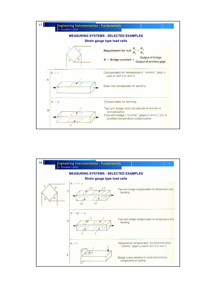
V. Rouillard 2003Engineering Instrumentation - Fundamentals17
MEASURING SYSTEMS : SELECTED EXAMPLES Strain gauge type load cells
V. Rouillard 2003Engineering Instrumentation - Fundamentals18
MEASURING SYSTEMS : SELECTED EXAMPLES Strain gauge type load cells
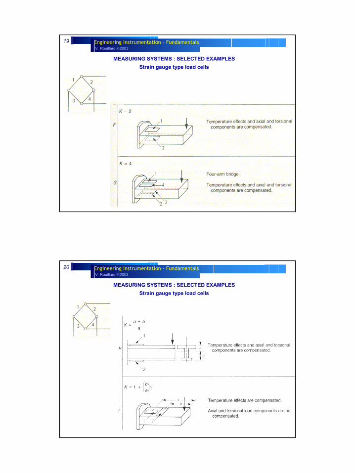
V. Rouillard 2003Engineering Instrumentation - Fundamentals19
MEASURING SYSTEMS : SELECTED EXAMPLES Strain gauge type load cells
V. Rouillard 2003Engineering Instrumentation - Fundamentals20
MEASURING SYSTEMS : SELECTED EXAMPLES Strain gauge type load cells
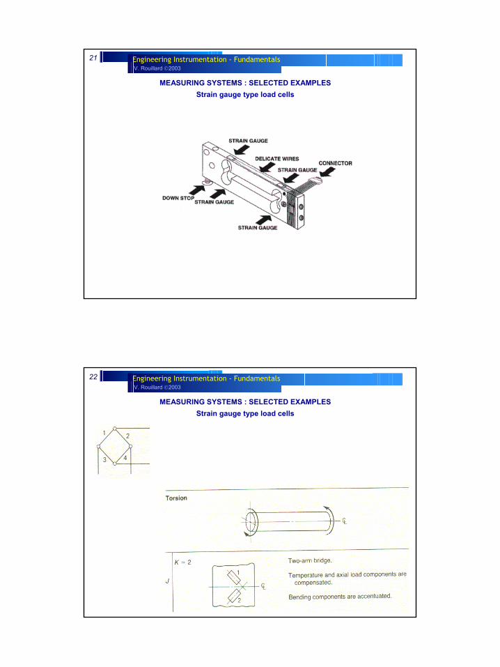
V. Rouillard 2003Engineering Instrumentation - Fundamentals21
MEASURING SYSTEMS : SELECTED EXAMPLES Strain gauge type load cells
V. Rouillard 2003Engineering Instrumentation - Fundamentals22
MEASURING SYSTEMS : SELECTED EXAMPLES Strain gauge type load cells
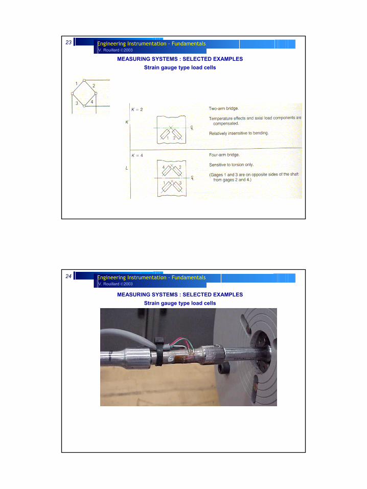
V. Rouillard 2003Engineering Instrumentation - Fundamentals23
MEASURING SYSTEMS : SELECTED EXAMPLES Strain gauge type load cells
V. Rouillard 2003Engineering Instrumentation - Fundamentals24
MEASURING SYSTEMS : SELECTED EXAMPLES Strain gauge type load cells
V. Rouillard 2003Engineering Instrumentation - Fundamentals25
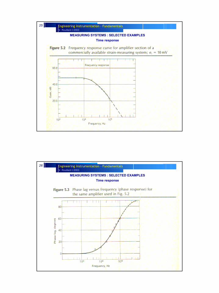
MEASURING SYSTEMS : SELECTED EXAMPLES Time response
V. Rouillard 2003Engineering Instrumentation - Fundamentals26
MEASURING SYSTEMS : SELECTED EXAMPLES Time response

V. Rouillard 2003Engineering Instrumentation - Fundamentals27
MEASURING SYSTEMS : SELECTED EXAMPLES Time response
V. Rouillard 2003Engineering Instrumentation - Fundamentals28
MEASURING SYSTEMS : SELECTED EXAMPLES Time response
V. Rouillard 2003Engineering Instrumentation - Fundamentals29
MEASURING SYSTEMS : SELECTED EXAMPLES Temperature
• Thermocouples are based on the principle that when two dissimilar metals are joined a predictable voltage will be generated that relates to the difference in temperature between the measuring junction and the reference junction (connection to the measuring device).
• RTDs are wire wound and thin film devices that work on the physical principle of the temperature coefficient of electrical resistance of metals. They are nearly linear over a wide range of temperatures and can be made small enough to have response times of a fraction of a second. They require an electrical current to produce a voltage drop across the sensor that can be then measured by a calibrated read-out device.
V. Rouillard 2003Engineering Instrumentation - Fundamentals30
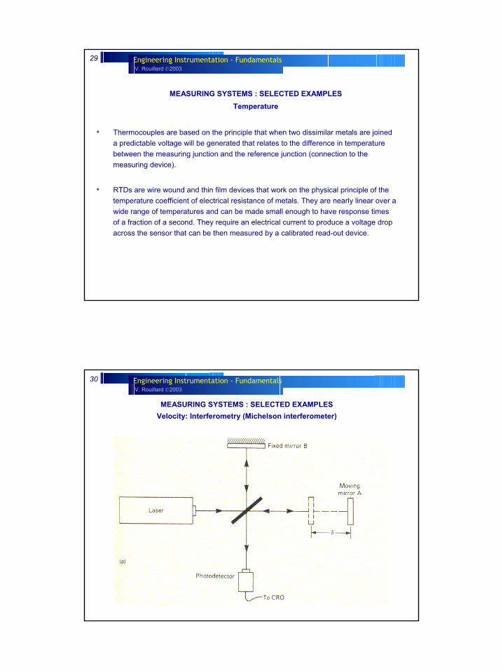
MEASURING SYSTEMS : SELECTED EXAMPLES Velocity: Interferometry (Michelson interferometer)
V. Rouillard 2003Engineering Instrumentation - Fundamentals31
MEASURING SYSTEMS : SELECTED EXAMPLES Velocity: Interferometry
V. Rouillard 2003Engineering Instrumentation - Fundamentals32
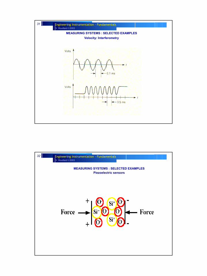
MEASURING SYSTEMS : SELECTED EXAMPLES Piezoelectric sensors
V. Rouillard 2003Engineering Instrumentation - Fundamentals33
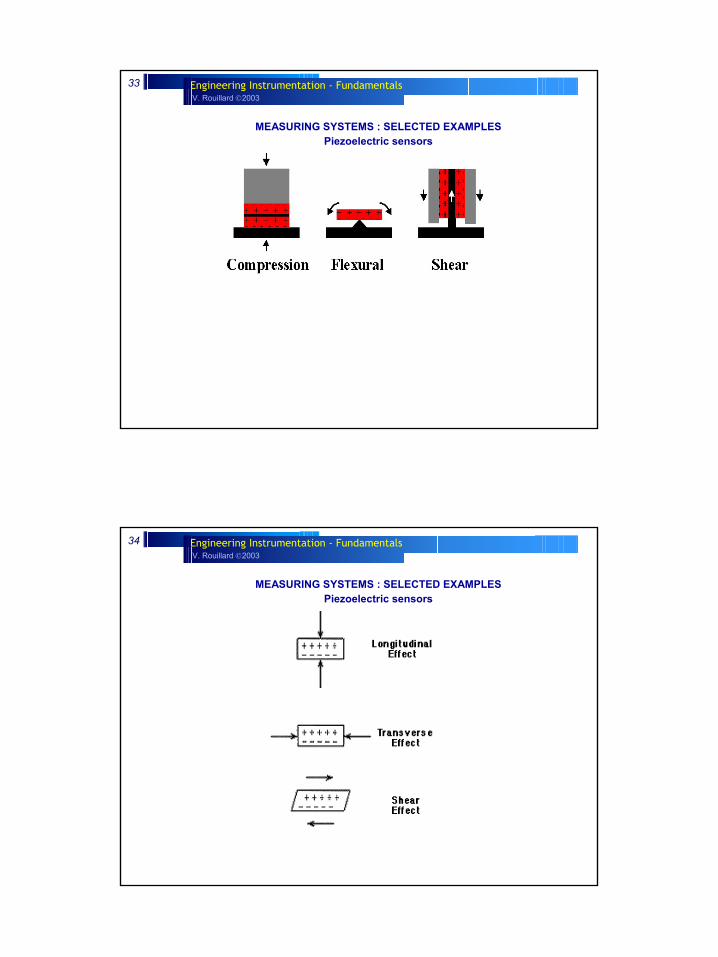
MEASURING SYSTEMS : SELECTED EXAMPLES Piezoelectric sensors
V. Rouillard 2003Engineering Instrumentation - Fundamentals34
MEASURING SYSTEMS : SELECTED EXAMPLES Piezoelectric sensors
V. Rouillard 2003Engineering Instrumentation - Fundamentals35
MEASURING SYSTEMS : SELECTED EXAMPLES Piezoelectric sensors
V. Rouillard 2003Engineering Instrumentation - Fundamentals36
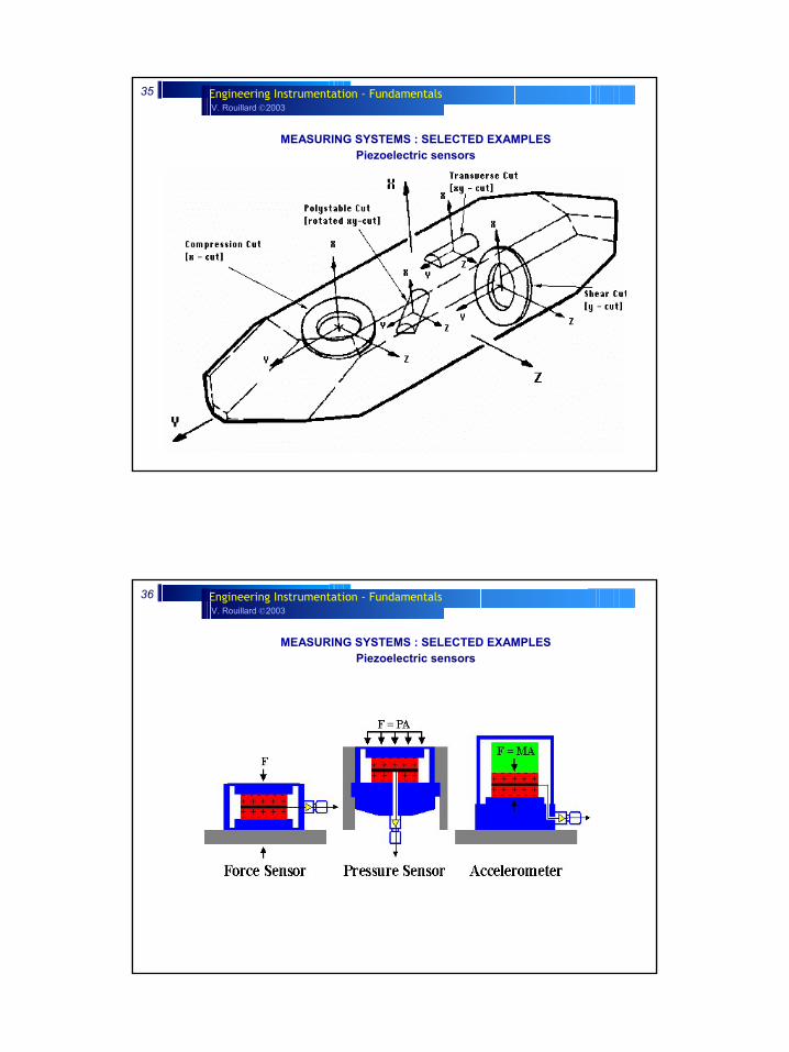
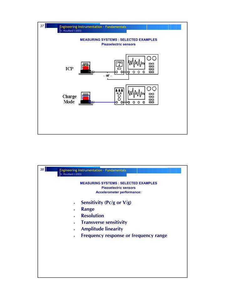
MEASURING SYSTEMS : SELECTED EXAMPLES Piezoelectric sensors
V. Rouillard 2003Engineering Instrumentation - Fundamentals37
MEASURING SYSTEMS : SELECTED EXAMPLES Piezoelectric sensors
V. Rouillard 2003Engineering Instrumentation - Fundamentals38
Sensitivity (Pc/g or V/g)RangeResolutionTransverse sensitivityAmplitude linearityFrequency response or frequency range
MEASURING SYSTEMS : SELECTED EXAMPLES Piezoelectric sensors
Accelerometer performance:
V. Rouillard 2003Engineering Instrumentation - Fundamentals39
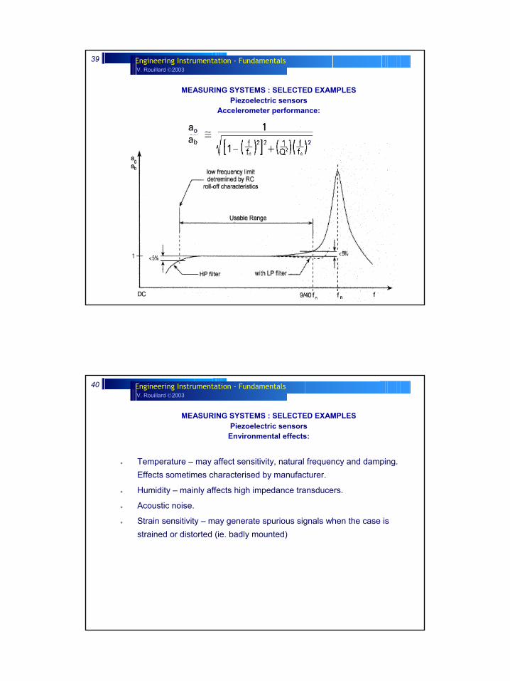
MEASURING SYSTEMS : SELECTED EXAMPLES Piezoelectric sensors
Accelerometer performance:
V. Rouillard 2003Engineering Instrumentation - Fundamentals40
Temperature – may affect sensitivity, natural frequency and damping. Effects sometimes characterised by manufacturer.
Humidity – mainly affects high impedance transducers.
Acoustic noise.
Strain sensitivity – may generate spurious signals when the case is strained or distorted (ie. badly mounted)
MEASURING SYSTEMS : SELECTED EXAMPLES Piezoelectric sensors
Environmental effects:
V. Rouillard 2003Engineering Instrumentation - Fundamentals41
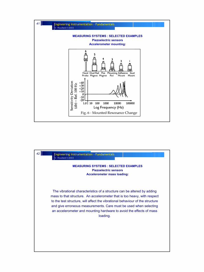
MEASURING SYSTEMS : SELECTED EXAMPLES Piezoelectric sensors
Accelerometer mounting:
V. Rouillard 2003Engineering Instrumentation - Fundamentals42
The vibrational characteristics of a structure can be altered by adding mass to that structure. An accelerometer that is too heavy, with respect to the test structure, will affect the vibrational behaviour of the structure and give erroneous measurements. Care must be used when selecting an accelerometer and mounting hardware to avoid the effects of mass
loading.
MEASURING SYSTEMS : SELECTED EXAMPLES Piezoelectric sensors
Accelerometer mass loading:
V. Rouillard 2003Engineering Instrumentation - Fundamentals43
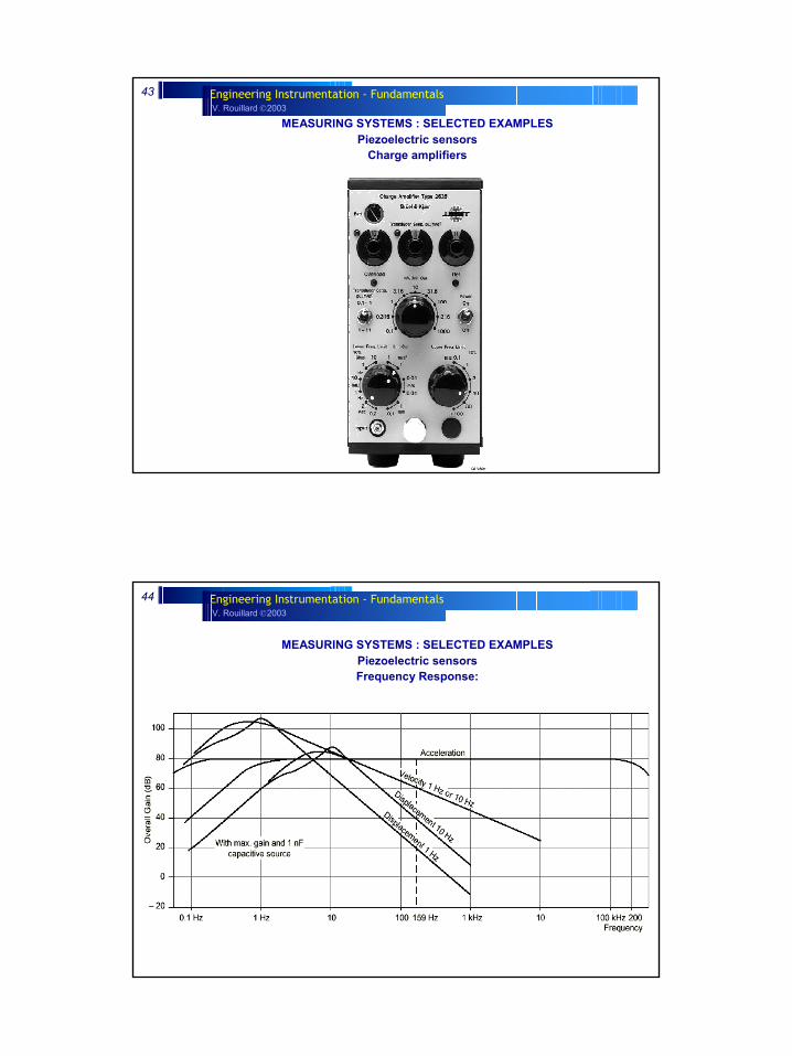
MEASURING SYSTEMS : SELECTED EXAMPLES Piezoelectric sensors
Charge amplifiers
V. Rouillard 2003Engineering Instrumentation - Fundamentals44
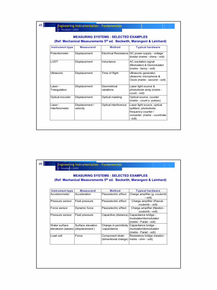
MEASURING SYSTEMS : SELECTED EXAMPLES Piezoelectric sensorsFrequency Response:
V. Rouillard 2003Engineering Instrumentation - Fundamentals45
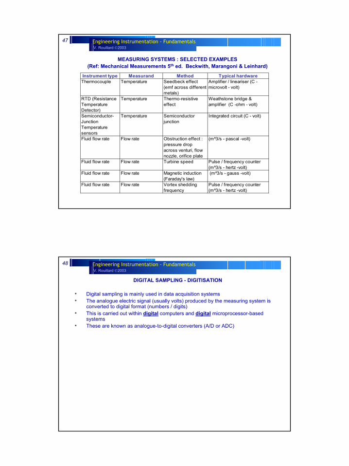
MEASURING SYSTEMS : SELECTED EXAMPLES(Ref: Mechanical Measurements 5th ed. Beckwith, Marangoni & Leinhard)
Instrument type Measurand Method Typical hardware
Potentiometer Displacement Electrical Resistance DC power supply - voltage divider (metre - ohms - volt)
LVDT Displacement Inductance AC excitation signal (Modulator) & Demodulator (metre - henry - volt)
Ultrasonic Displacement Time of flight Ultrasonic generator, ultrasonic microphone & Clock (metre - second - volt)
Laser - Triangulation
Displacement Geometrical variations
Laser light source & photodiode array (metre - count - volt)
Optical encoder Displacement Optical masking Optical source, counter (metre - count s- pulses)
Laser - Interferometer
Displacement / velocity
Optical interference Laser light source, optical splitters, photodiode, frequency counter / converter. (metre - count/rate - volt)
V. Rouillard 2003Engineering Instrumentation - Fundamentals46
Instrument type Measurand Method Typical hardwareAccelerometer Acceleration Piezoelectric effect Charge amplifier (g -coulomb
- volt)Pressure sensor Fluid pressure Piezoelectric effect Charge amplifier (Pascal -
coulomb - volt)Force sensor Dynamic force Piezoelectric effect Charge amplifier (Newton -
coulomb - volt)Pressure sensor Fluid pressure Capacitive (distance) Capacitance bridge -
modulator/demodulator (metre - Farad - volt)
Water surface elevatuion (waves)
Surface elevation (displacement )
Change in permitivity -capacitance
Capacitance bridge - modulator/demodulator (metre - Farad - volt)
Load cell Force Component strain (dimentional change)
Resistance bridge (newton -metre - ohm - volt)
MEASURING SYSTEMS : SELECTED EXAMPLES(Ref: Mechanical Measurements 5th ed. Beckwith, Marangoni & Leinhard)
V. Rouillard 2003Engineering Instrumentation - Fundamentals47
Instrument type Measurand Method Typical hardwareThermocouple Temperature Seedbeck effect
(emf across different metals)
Amplifier / lineariser (C -microvolt - volt)
RTD (Resistance Temperature Detector)
Temperature Thermo-resistive effect
Weathstone bridge & amplifier (C -ohm - volt)
Semiconductor-Junction Temperature sensors
Temperature Semiconductor junction
Integrated circuit (C - volt)
Fluid flow rate Flow rate Obstruction effect : pressure drop across venturi, flow nozzle, orifice plate
(m 3̂/s - pascal -volt)
Fluid flow rate Flow rate Turbine speed Pulse / frequency counter (m 3̂/s - hertz -volt)
Fluid flow rate Flow rate Magnetic induction (Faraday's law)
(m 3̂/s - gauss -volt)
Fluid flow rate Flow rate Vortex shedding frequency
Pulse / frequency counter (m 3̂/s - hertz -volt)
MEASURING SYSTEMS : SELECTED EXAMPLES(Ref: Mechanical Measurements 5th ed. Beckwith, Marangoni & Leinhard)
V. Rouillard 2003Engineering Instrumentation - Fundamentals48
DIGITAL SAMPLING - DIGITISATION
• Digital sampling is mainly used in data acquisition systems• The analogue electric signal (usually volts) produced by the measuring system is
converted to digital format (numbers / digits)• This is carried out within digital computers and digital microprocessor-based
systems• These are known as analogue-to-digital converters (A/D or ADC)
V. Rouillard 2003Engineering Instrumentation - Fundamentals49
DIGITAL SAMPLING - DIGITISATION
Main reasons for using digital sampling systems:• Unlike analogue recording systems enable the recorded data to be analysed and
manipulated• ADC’s can operate at great speeds (MHz) and can therefore be used to capture
rapid changes in the measured quantity (sound – up to 20 kHz, mechanical impacts, pyrotechnic loads – up to 100’s kHz)
• ADC’s can be programmed to capture data automatically at very long intervals (eg: tides, or based on the process level (triggered systems)
• Information is stored permanently• Information can be accessed remotely• Information can be used as part of a control system• Digital circuits use relatively low power, low voltages → safer
V. Rouillard 2003Engineering Instrumentation - Fundamentals50
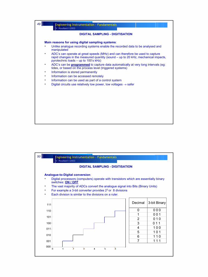
DIGITAL SAMPLING - DIGITISATION
Analogue-to-Digital conversion:• Digital processors (computers) operate with transistors which are essentially binary
switches: ON / OFF• The vast majority of ADCs convert the analogue signal into Bits (Binary Units)• For example a 3-bit converter provides 23 or 8 divisions• Each division is similar to the divisions on a ruler.
Decimal 3-bit Binary
0 0 0 01 0 0 12 0 1 03 0 1 1 4 1 0 05 1 0 16 1 1 07 1 1 1
000
100
111
101
011
010
001
110
V. Rouillard 2003Engineering Instrumentation - Fundamentals51
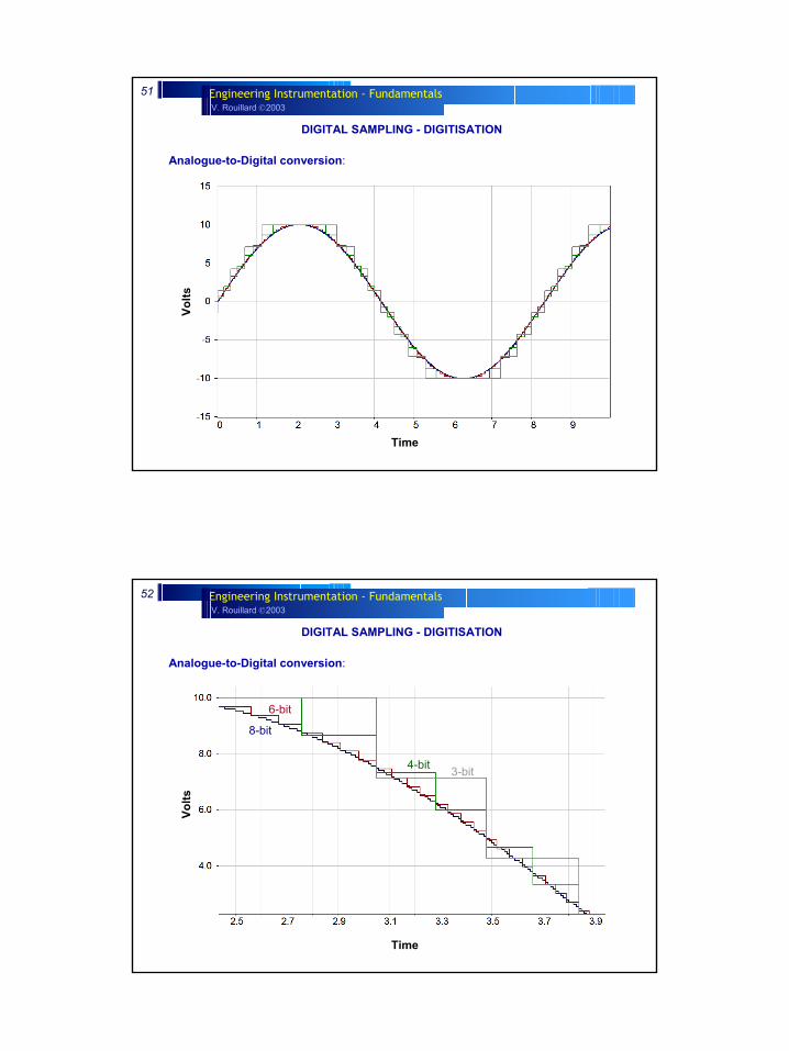
DIGITAL SAMPLING - DIGITISATION
Analogue-to-Digital conversion:
Time
Volts
V. Rouillard 2003Engineering Instrumentation - Fundamentals52
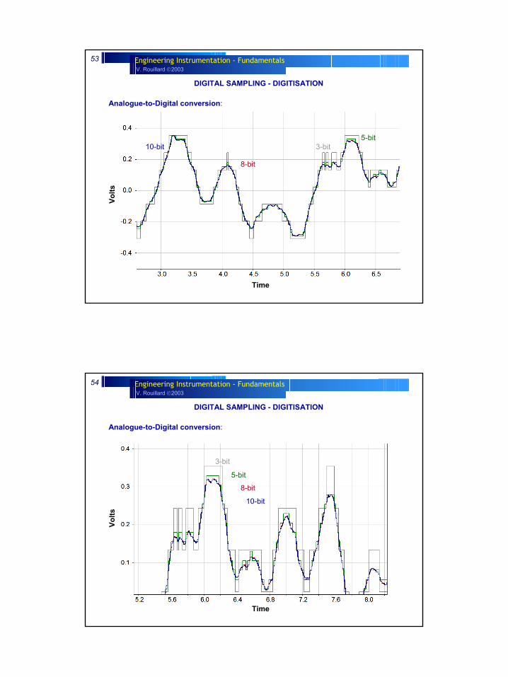
DIGITAL SAMPLING - DIGITISATION
Analogue-to-Digital conversion:
Time
Volts
3-bit
6-bit
8-bit
4-bit
V. Rouillard 2003Engineering Instrumentation - Fundamentals53
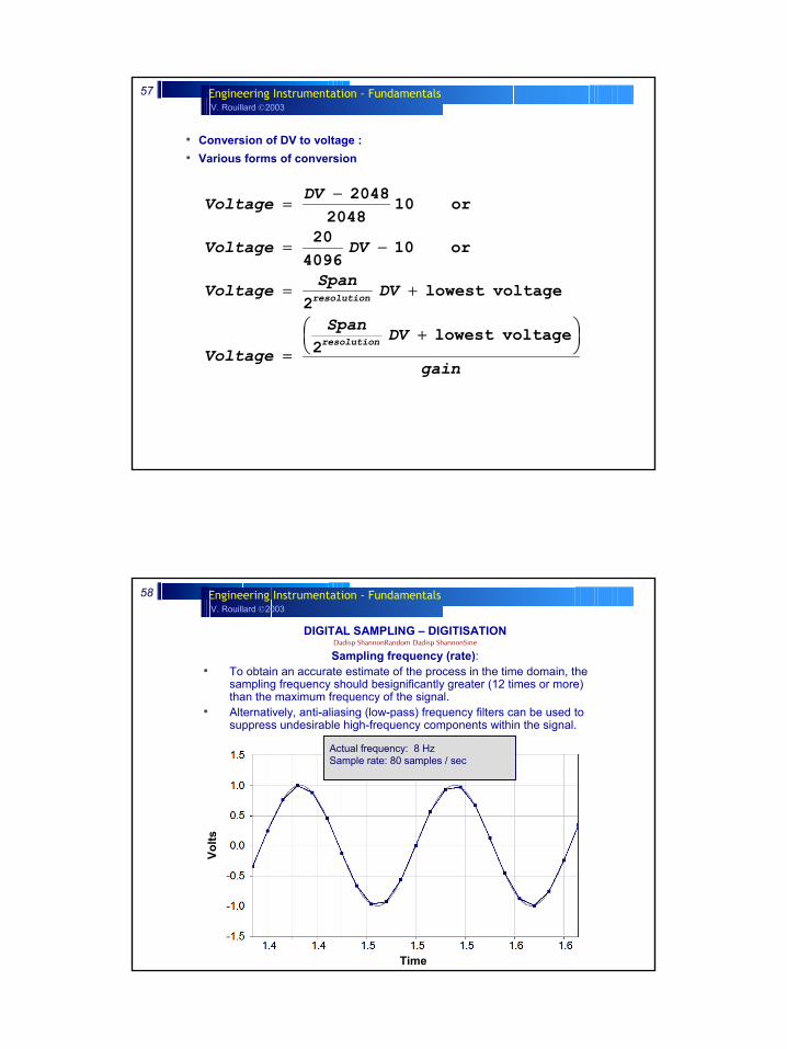
DIGITAL SAMPLING - DIGITISATION
Analogue-to-Digital conversion:
Time
Volts
3-bit
8-bit
10-bit5-bit
V. Rouillard 2003Engineering Instrumentation - Fundamentals54
DIGITAL SAMPLING - DIGITISATION
Analogue-to-Digital conversion:
Time
Volts
3-bit
8-bit
10-bit
5-bit

V. Rouillard 2003Engineering Instrumentation - Fundamentals55
DIGITAL SAMPLING - DIGITISATION
Analogue-to-Digital conversion:• Most modern ADC operate with at least 12-bit (212 = 4096) conversion and up to 24-
bit (224 = 16777216)• The resolution of the ADC, εv, is determined by:
• For example, a 12 Bit ADC with a voltage range of ± 10 Volts has a resolution of 20/4096 = 4.88 mV
εv fsn
fs
V
where V is the full scale voltage rangeand n is the number of bits of the ADC
=
−
∆
∆2
V. Rouillard 2003Engineering Instrumentation - Fundamentals56
DIGITAL SAMPLING - DIGITISATION
Dynamic Range:• The dynamic range of ADC are often specified in dB.
• For bi-polar ADC (measures positive & negative signals) the dynamic range is:Dynamic range = 20 log (2r/2)Eg. 12 bit conversion: 20 log (212/2) = 20 log 4096/2 = 66 dBEg. 16 bit conversion: 20 log (216/2) = 20 log 65536/2 = 90 dB
• For bi-polar ADC (measures positive & negative signals) the dynamic range is:Dynamic range = 20 log (2r)Eg. 12 bit conversion: 20 log (212) = 20 log 4096= 72 dB
V. Rouillard 2003Engineering Instrumentation - Fundamentals57
• Conversion of DV to voltage :• Various forms of conversion
gain
DVSpan
Voltage
DVSpanVoltage
DVVoltage
DVVoltage
resolution
resolution
+
=
+=
−=
−=
voltage lowest2
voltage lowest2
or10409620
or1020482048
Specific cases
V. Rouillard 2003Engineering Instrumentation - Fundamentals58
DIGITAL SAMPLING – DIGITISATIONDadisp ShannonRandom Dadisp ShannonSine
Sampling frequency (rate):• To obtain an accurate estimate of the process in the time domain, the
sampling frequency should besignificantly greater (12 times or more) than the maximum frequency of the signal.
• Alternatively, anti-aliasing (low-pass) frequency filters can be used to suppress undesirable high-frequency components within the signal.
Time
Volts
Actual frequency: 8 Hz Sample rate: 80 samples / sec
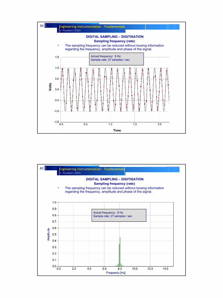
V. Rouillard 2003Engineering Instrumentation - Fundamentals59
DIGITAL SAMPLING – DIGITISATIONSampling frequency (rate):
• The sampling frequency can be reduced without loosing information regarding the frequency, amplitude and phase of the signal.
Time
Volts
Actual frequency: 8 Hz Sample rate: 27 samples / sec
V. Rouillard 2003Engineering Instrumentation - Fundamentals60
DIGITAL SAMPLING – DIGITISATIONSampling frequency (rate):
• The sampling frequency can be reduced without loosing information regarding the frequency, amplitude and phase of the signal.
Actual frequency: 8 Hz Sample rate: 27 samples / sec
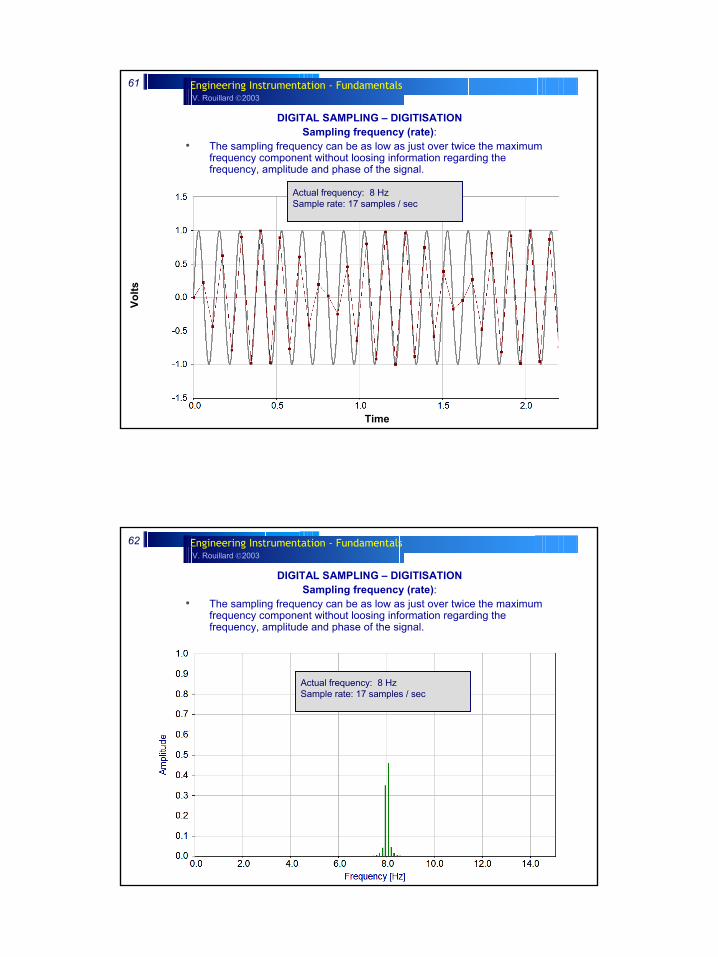
V. Rouillard 2003Engineering Instrumentation - Fundamentals61
DIGITAL SAMPLING – DIGITISATIONSampling frequency (rate):
• The sampling frequency can be as low as just over twice the maximum frequency component without loosing information regarding the frequency, amplitude and phase of the signal.
Time
Volts
Actual frequency: 8 Hz Sample rate: 17 samples / sec
V. Rouillard 2003Engineering Instrumentation - Fundamentals62
DIGITAL SAMPLING – DIGITISATIONSampling frequency (rate):
• The sampling frequency can be as low as just over twice the maximum frequency component without loosing information regarding the frequency, amplitude and phase of the signal.
Actual frequency: 8 Hz Sample rate: 17 samples / sec
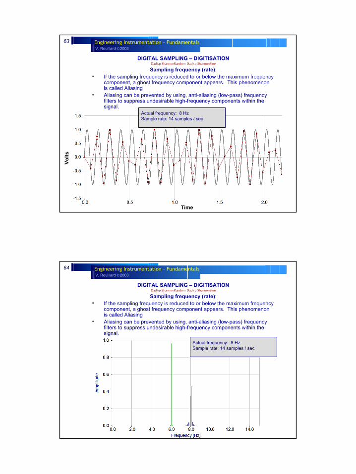
V. Rouillard 2003Engineering Instrumentation - Fundamentals63
DIGITAL SAMPLING – DIGITISATIONDadisp ShannonRandom Dadisp ShannonSine
Sampling frequency (rate):• If the sampling frequency is reduced to or below the maximum frequency
component, a ghost frequency component appears. This phenomenonis called Aliasing
• Aliasing can be prevented by using, anti-aliasing (low-pass) frequency filters to suppress undesirable high-frequency components within the signal.
Actual frequency: 8 Hz Sample rate: 14 samples / sec
Time
Volts
V. Rouillard 2003Engineering Instrumentation - Fundamentals64
DIGITAL SAMPLING – DIGITISATIONDadisp ShannonRandom Dadisp ShannonSine
Sampling frequency (rate):• If the sampling frequency is reduced to or below the maximum frequency
component, a ghost frequency component appears. This phenomenonis called Aliasing
• Aliasing can be prevented by using, anti-aliasing (low-pass) frequency filters to suppress undesirable high-frequency components within the signal.
Actual frequency: 8 Hz Sample rate: 14 samples / sec
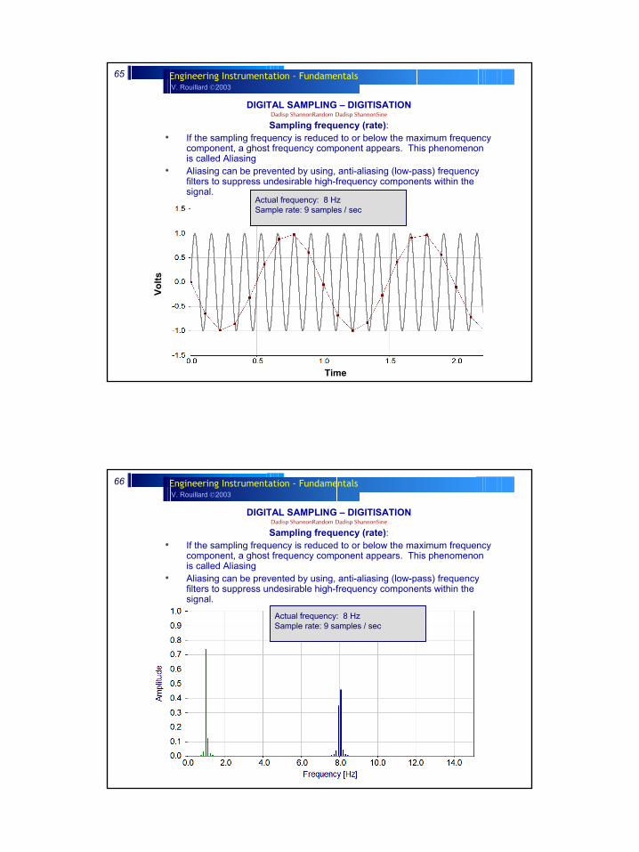
V. Rouillard 2003Engineering Instrumentation - Fundamentals65
DIGITAL SAMPLING – DIGITISATIONDadisp ShannonRandom Dadisp ShannonSine
Sampling frequency (rate):• If the sampling frequency is reduced to or below the maximum frequency
component, a ghost frequency component appears. This phenomenonis called Aliasing
• Aliasing can be prevented by using, anti-aliasing (low-pass) frequency filters to suppress undesirable high-frequency components within the signal.
Actual frequency: 8 Hz Sample rate: 9 samples / sec
Time
Volts
V. Rouillard 2003Engineering Instrumentation - Fundamentals66
DIGITAL SAMPLING – DIGITISATIONDadisp ShannonRandom Dadisp ShannonSine
Sampling frequency (rate):• If the sampling frequency is reduced to or below the maximum frequency
component, a ghost frequency component appears. This phenomenonis called Aliasing
• Aliasing can be prevented by using, anti-aliasing (low-pass) frequency filters to suppress undesirable high-frequency components within the signal.
Actual frequency: 8 Hz Sample rate: 9 samples / sec