evc b14n it4x - neptronic · evcb1 4nit4x-v410-modb m us guide-170524-e odbu sa.docx 4 tria s com...
TRANSCRIPT

EVCB1
14NIT4X-V410-Modb
M
bus Guide-170524-E
Modbu
SA.docx
4 TRIA
s Com
EVCACS / pressu
mmunic
CB14Nure independ
cation
IT4X dent/external
Modul
l motor
e Use
r Guide

EVCB14NIT4X Modbus Communication Module User Guide
www.neptronic.com Page | 1
Introduction The EVCB Series Modbus Communication Module User Guide provides information for using Neptronic® communication feature. The controller uses Modbus communication protocol over serial line in the RTU mode and provides a Modbus network interface between client devices and Neptronic EVCB Series devices. The EVCB Series Modbus Guide assumes that you are familiar with Modbus terminology. The following are the requirements for Modbus:
Data Model. The EVCB Modbus server data model uses only the Holding Registers table.
Function Codes. The EVCB Modbus server supports a limited function codes subset comprising:
o Read Holding Registers (0x03)
o Write Single Register (0x06)
o Write Multiple Registers (0x10)
Exception Responses. The EVCB Modbus server supports the following exception codes:
o Illegal data address
o Illegal data value
o Slave device busy
Serial Line. The EVCB Modbus over serial line uses RTU transmission mode over a two-wire configuration RS485 (EIA/TIA-485 standard) physical layer.
o The physical layer can use fixed baud rate selection or automatic baud rate detection (default) as per the Modbus Auto Baud Rate device menu item or holding register index 1.
o The supported baud rates are 9600, 19200, 38400, and 57600.
o The physical layer also supports variable parity control and stop bit configuration as per the Modbus Comport Config device menu item or holding register index 2.
o In auto baud rate configuration, if the device detects only consecutive bad frames (2 or more) for one second with any given baud rate, it will reinitialize itself to the next baud rate.
Addressing. The EVCB device only answers at the following address:
o The device's unique address (1 to 246) that can be set through the device menu or through holding register index 0.

EVCB14NIT4X Modbus Communication Module User Guide
www.neptronic.com Page | 2
Holding Registers Table
Table Glossary Name Description Name Description
W Writable Register ASCII For registers containing ASCII (8-bit) characters
RO Read Only Register MSB Most Significant Byte
Unsigned For range of values from 0 to 65,535, unless otherwise specified LSB Least Significant Byte
Signed For range of values from -32,768 to 32,767, unless otherwise specified MSW Most Significant Word
Bit String For registers with multiple values using bit mask (example, flags) LSW Least Significant Word
Holding Register Table
Register Index
Description Data Type Range Writable
40000 Modbus Address and Product Type. Unsigned MSB = Product type (e.g. 111 for EVCB) LSB = Modbus Address (e.g. 1-246)
W
40001 MSTP Baud Rate. Unsigned Scale 100
0, 9600, 19200, 38400, or 57600 0 = Auto Baud Rate Detection Value/100 (e.g. 38400 baud = 384)
W
40002 Modbus Slave Communication Port Configuration. Unsigned 1= No parity, 2 Stop bits 2= Even parity, 1 stop bit 3= Odd parity, 1 stop bit
W
40003 Product Name (characters 8 & 7). ASCII
1 to 65,535 char 8: 0x53 = S char 7: 0x00 = W
40004 Product Name (characters 6 & 5). ASCII 1 to 65535 char 6: 0x49 = I char 5: 0x34 = 4 W
40005 Product Name (characters 4 & 3). ASCII 1 to 65535 char 4: 0x42 = B char 3: 0x4E = N W
40006 Product Name (characters 2 & 1). ASCII 1 to 65535 char 2: 0x45 = E char 1: 0x56 = V W

EVCB14NIT4X Modbus Communication Module User Guide
www.neptronic.com Page | 3
Register Index
Description Data Type Range Writable
40007 Product actual firmware version. Unsigned 1 to 65535 (e.g. 409) RO
40008 Product actual EEPROM version. Unsigned 1 to 65535 (e.g. 203) RO
40009 System Status 1. Bit String
[B0 – B11]: Reserved
B12: CO2 alarm 0 = Normal; 1 = Alarm
B13: Pressure mode (actual status) 0 = Independent; 1 = Dependent
B14: Air Flow 0 = Normal; 1 = Error
RO
40010 System Status 2. Bit String
[B0-B11, B13-B14]: Reserved B12: Alarm override 0 = Normal; 1 = Alarm
RO
40011 Internal Temperature. Unsigned Scale 100
0 to 5000 Value x 100 (e.g. 23°C = 2300)
RO
40012 External Temperature. Signed
Scale 100
-4000 to 10000 Value x 100 (e.g. 18°C = 1800)
RO
40013 Change Over Temperature. Signed
Scale 100
-4000 to 10000 Value x 100 (e.g. 18°C = 1800)
RO
40014 Internal humidity, reading of the integrated humidity sensor of TRLH or TRLGH. If not available the value will be fixed to 0x7FFF (32767)
Signed Scale 10
0 to 1000 Value x 10 (e.g. 45%RH = 450)
RO
40015 Input 3 reading, pressure sensor value Unsigned 0 to 4000 mV RO
40016 Analog input 1 value. Unsigned Scale 100
0 to 1000 Value x 100 (e.g. 2 mV = 200)
RO
40017 Analog Input 2 value. Unsigned Scale 100
0 to 1000 Value x 100 (e.g. 3 mV = 300)
RO
40018 CO2 value in ppm: If using AI1 or AI2 and CO2 is set in Analog mode, the reading is from the external sensor.
Unsigned Scale 100
100 to reg 40098 Value x 100 (e.g. 5 ppm = 500)
RO

EVCB14NIT4X Modbus Communication Module User Guide
www.neptronic.com Page | 4
Register Index
Description Data Type Range Writable
40019 Air supply temperature. Signed
Scale 100 -4000 to 10000 Value x 100 (e.g. 5°C = 500)
RO
40020 Control temperature. Signed
Scale 100 -4000 to 10000 Value x 100 (e.g. 25°C = 2500)
W
40021 Heating demand for heating ramp 1. Unsigned Scale 10
0 to 1000 Value x 10 (e.g. 25% = 250)
RO
40022 Cooling demand for cooling ramp 1. Unsigned Scale 10
0 to 1000 Value x 10 (e.g. 25% = 250)
RO
40023 Temperature offset applied on internal temperature. Signed
Scale 100 -500 to 500 Value x 100 (e.g. 0.5°C = 50)
W
40024 Temperature offset applied on external temperature. Signed
Scale 100 -500 to 500 Value x 100 (e.g. 0.5°C = 50)
W
40025 Temperature setpoint used during the occupancy period of the day. Unsigned Scale 10
Range: 40026 to 40027 Value x 10 (e.g. 20°C = 200)
W
40026 Minimum temperature setpoint used during the day. Unsigned Scale 10
Range: 100 to 40027 Value x 10 (e.g. 10°C = 100)
W
40027 Maximum temperature setpoint used during the day. Unsigned Scale 10
Range: 40026 to 400 Value x 10 (e.g. 40°C = 400)
W
40028 Cooling setpoint during No Occupancy / Night Set Back Unsigned Scale 10
Range: 40029 to 400 Value x 10 (e.g. 22°C = 220)
W
40029 Heating setpoint during No Occupancy / Night Set Back Unsigned Scale 10
Range: 100 to 40028 Value x 10 (e.g. 16°C = 160)
W
40030 Cooling demand for proportional band 1. Unsigned Scale 10
5 to 50 Value x 10 ( e.g. 0.3°C = 3)
W
40031 Heating demand for proportional band 1. Unsigned Scale 10
5 to 50 Value x 10 (e.g. 0.3°C = 3)
W
40032 Cooling dead band for proportional band 1. Unsigned Scale 10
0 to 50 Value x 10 (e.g. 0.3°C = 3)
W

EVCB14NIT4X Modbus Communication Module User Guide
www.neptronic.com Page | 5
Register Index
Description Data Type Range Writable
40033 Heating dead band for proportional band 1. Unsigned Scale 10
0 to 50 Value x 10 (e.g. 0.3°C = 3)
W
40034 Changeover temperature setpoint. Unsigned Scale 10
100 to 400 Value x 10 (e.g. 12°C = 120)
W
40035 Night setback override delay in minutes. Unsigned 0 to 180 minutes W
40036 Integral time factor for heating in seconds. Unsigned 0 to 250 seconds W
40037 Cooling anti-cycle delay: delay in minutes before activating or reactivating the cooling contact.
Unsigned 0 to 15 minutes W
40038 Floating time 1: Indicates the time in seconds required by the actuator to complete a 90° run.
Unsigned 15 to 250 seconds W
40039 Occupancy Delay Mode in minutes Unsigned 0 to 180 minutes W
40040 Cooling demand for cooling ramp 2. Unsigned Scale 10
0 to 1000 % Value x 10 (e.g. 30% = 300)
RO
40041 Proportional band for cooling ramp 2 Unsigned Scale 10
5 to 50 Value x 10 (e.g. 0.2°C = 2)
W
40042 Dead band for cooling ramp 2. Unsigned Scale 10
0 to 50 Value x 10 (e.g. 0.2°C = 2)
W
40043 Heating demand for heating ramp 2. Unsigned Scale 10
0 to 1000 % Value x 10 (e.g. 30% = 300)
W
40044 Proportional band for heating ramp 2. Unsigned Scale 10
5 to 50 Value x 10 (e.g. 0.2°C = 2)
W
40045 Dead band for heating ramp 2. Unsigned Scale 10
0 to 50 Value x 10 (e.g. 0.2°C = 2)
W
40046 Changeover demand for the VAV box. Unsigned Scale 10
0 to 1000 % Value x 10 (e.g. 30% = 300)
RO
40047 Changeover proportional band: the range in which the controller modulates the cooling and heating output from 0 to 100%.
Unsigned Scale 10
5 to 50 Value x 10 (e.g. 0.2°C = 2)
W

EVCB14NIT4X Modbus Communication Module User Guide
www.neptronic.com Page | 6
Register Index
Description Data Type Range Writable
40048 Changeover deadband: the range at which the controller takes no action when the temperature is above or below the setpoint.
Unsigned Scale 10
0 to 50 Value x 10 (e.g. 0.2°C = 2)
W
40049 AO1 min Vdc: minimum voltage of analog output 1. Unsigned Scale 10
Range: 0 to reg. 40051 Value x 10 (e.g. 2 Volts = 20)
W
40050 AO2 min Vdc: minimum voltage of analog output 2. Unsigned Scale 10
Range: 0 to reg. 40052 Value x 10 (e.g. 2 Volts = 20)
W
40051 AO1 max Vdc: maximum voltage of analog output 1. Unsigned Scale 10
Range: reg. 40049 to 100 Value x 10 (e.g. 10 Volts = 100)
W
40052 AO2 max Vdc: maximum voltage of analog output 2. Unsigned Scale 10
Range: reg. 40050 to 100 Value x 10 (e.g. 10 Volts = 100)
W
= The minimum and maximum voltages correspond to 0 to 100% demand. The minimum voltage is always applied to the output. The maximum voltage is applied when the demand reaches 100%. For reheat applications, we recommend to leave the minimum voltage at 0Vdc to avoid heating when the demand is 0%.
40053 Time of numerical filter of delta pressure in seconds. Unsigned 1 to 10 seconds W
40054 Factor of V=K*sqrt(dP), where dP = 1. Unsigned Range: 100 to 9995 CFM W
40055 Minimum air flow for cooling. Unsigned Range: 0 or (12.7%) Kfac to reg 40056 CFM W
40056 Maximum air flow for cooling. Unsigned Range: reg 40055 to reg 40054 CFM W
40057 Minimum air flow for heating. Unsigned Range: 0 or (12.7%) Kfac to reg 40058 CFM W
40058 Maximum air flow for heating. Unsigned Range: reg 40057 to reg 40054 CFM W
40059 Integral time factor of air flow in minutes. Unsigned 0 to 60 minutes W
40060 Actual air flow converted from delta pressure sensor. Unsigned Range: 0 to reg 40054 CFM RO
40061 Air flow calculated from system demand. Unsigned Range: 0 to 9999 CFM RO
40062 Configuration value for Air Flow Max used during airflow balancing sequence. Refer to EVCB-Airflow Balance Instructions.
Unsigned Range: 0 to 9999 CFM W
40063 Analog output 1 value. Unsigned Scale 10
Unit: Volt, Range: reg 40049 to reg 40051 Value x 10 (e.g. 5 Volts = 50)
W
40064 Analog output 2 value. Unsigned Scale 10
Unit: Volt, Range: reg 40050 to reg 40052 Value x 10 (e.g. 5 Volts = 50)
W

EVCB14NIT4X Modbus Communication Module User Guide
www.neptronic.com Page | 7
Register Index
Description Data Type Range Writable
40065 Percentage of demand to close TRIAC output 1. Unsigned 15 to 80% W
40066 Percentage of demand to close TRIAC output 2. Unsigned 15 to 80% W
40067 Percentage of demand to close TRIAC output 3. Unsigned 15 to 80% W
40068 Percentage of demand to close TRIAC output 4. Unsigned 15 to 80% W
40069 Percentage of demand to open TRIAC output 1. Unsigned 0 to reg 40065-4% W
40070 Percentage of demand to open TRIAC output 2. Unsigned 0 to reg 40065-4% W
40071 Percentage of demand to open TRIAC output 3. Unsigned 0 to reg 40065-4% W
40072 Percentage of demand to open TRIAC output 4. Unsigned 0 to reg 40065-4% W
40073 Integral time factor for cooling in seconds. Unsigned 0 to 250 seconds W
40074 Motor position.
Unsigned 0 to 100% RO
40075 to 40080 - Reserved RO
40081 Air flow offset calibration. Refer to EVCB-Airflow Balance Instructions.
Signed -500 to 500 CFM W
40084 Configuration value for Air Flow Min used during airflow balancing sequence. Refer to EVCB-Airflow Balance Instructions.
Unsigned Range: 0 to 9999 CFM W
40082, 40083, and 40085 to 40095 - Reserved RO
40096 Network fallback timeout Present Value in minutes. Unsigned 0 to 60 minutes W
40097 Reserved RO
40098 Maximum range of the CO2 sensor connected to AI1 or AI2. Unsigned 100 to 5000 PPM W
40099 Maximum concentration of CO2 before the EVC activates an alarm. Unsigned Range: 100 to the greater ppm value between 2000 and reg 40098 W

EVCB14NIT4X Modbus Communication Module User Guide
www.neptronic.com Page | 8
Register Index
Description Data Type Range Writable
40100 System Option 1. Bit String
B3, B13-B14: Reserved B0: Tstat temperature units 0 = Celsius; 1 = Fahrenheit B1: Modbus temperature units 0 = Celsius; 1 = Fahrenheit B2: Temperature setpoint lock 0 = Unlocked; 1 = Locked B4: TO1/TO2 floating direction 0 = Direct; 1 = Reverse B5: TO3/TO4 floating direction 0 = Direct; 1 = Reverse B6: Onboard motor direction 0 = Direct; 1 = Reverse
B7: Freeze protection 0 = Disabled; 1 = Enabled B8: User system off mode 0 = User can set Tstat to OFF 1 = User cannot set Tstat OFF B9: Keypad bottom left lock 0 = Unlocked; 1 = Locked B10:Keypad upper left lock 0 = Unlocked; 1 = Locked B11: Keypad arrows lock 0 = Unlocked; 1 = Locked B12: Program lock 0 = Unlocked; 1 = Locked B15: Schedule 0 = Disabled; 1 = Enabled
W
40101 System Option 2. Notes B14: Applies only if DI2 is in OverHeat or Override.
Bit String
B0-B1, B10, B13, B15: Reserved B2: Auto baud rate detection 0 = Enabled; 1 = Disabled B3: Night setback mode 0 = Tstat ON; 1 = Tstat OFF B4: AO1 direction 0 = Direct; 1 = Reverse B5: AO2 direction 0 = Direct; 1 = Reverse B6: TO1 direction 0 = Direct; 1 = Reverse B7: TO2 direction 0 = Direct; 1 = Reverse
B8: TO3 direction 0 = Direct; 1 = Reverse B9: TO4 direction 0 = Direct; 1 = Reverse B10: Display RH 0 = No; 1 = Yes B11: Pressure mode select 0 = independent;1 = dependent B12: Auto pressure modechange 0 = Enabled; 1 = Disabled B14: DI 2 Contact 0: NO; 1: NC
W

EVCB14NIT4X Modbus Communication Module User Guide
www.neptronic.com Page | 9
Register Index
Description Data Type Range Writable
40102 Status value of the actual changeover control mode. Unsigned 0 = Cooling , 1= Heating RO
40103 System command status. Unsigned 0 = No Command 1 = AirFlow 1 Balancing 4 = AirFlow 2 Balancing
W
40104 TO OnOff. Unsigned
1 = TO1 OnOff 2 = TO2 OnOff 4 = TO3 OnOff 8 = TO4 OnOff
RO
40105 Occupancy or night setback mode commands. Unsigned
1 = Locally 2 = Off 3 = Occupancy 4 = NoOccupancy 5 = Day 6 = Night
W
40106 Status of digital input 1. Unsigned 0 = Open 1 = Close
RO
40107 Analog input 1 signal. Unsigned
1 = OFF 2 = ETS (external temp) 3 = SENS (changeover sensor) 4 = NoCL (normally cool) 5 = NoHT (normally heat)
6 = STFL (setpnt airflow 0-10Vdc) 7 = CO2 (carbon dioxide) 8 = AST (air supply temp sensor) 9 = mor (motor position)
W
40108 User System Control Mode. Unsigned
1 = AUTO 2 = HEAT 3 = COOL 4 = OFF
W
40109 Sets the permissions or restrictions to change the system control mode by the user.
Unsigned
1 = AUTO 2 = HEAT 3 = COOL 4 = COOL-HEAT 5 = AUTO-LOCK
W
40110 Indicates the status of the Night Setback mode.
Unsigned 1 = Day 2 = Night 3 = Derogation
RO
40111 Configuration of DI1 mode. Night setback or no occupancy status.
Unsigned 1=Off 2= Occupancy NO 3= Occupancy NC
4= Night Set Back NO 5= Night Set Back NC W

EVCB14NIT4X Modbus Communication Module User Guide
www.neptronic.com Page | 10
Register Index
Description Data Type Range Writable
40112 Analog input 2 signal. Unsigned
1 = OFF 2 = ETS (external temp) 3 = SENS (changeover sensor) 4 = NoCL (normally cool) 5 = NoHT (normally heat)
6 = STFL (setpnt airflow 0-10Vdc) 7 = CO2 (carbon dioxide) 8 = AST (air supply temp sensor) 9 = mor (motor position)
W
40113 Occupancy status of the zone. Unsigned 1 = No Occupancy 2 = Occupancy 3 = Derogation
RO
40114 AO1: Analog output 1 control ramp Unsigned
1 = OFF 2 = CR1 (cooling ramp 1) 3 = CR2 (cooling ramp 2) 4 = HR1 (heating ramp 1) 5 = HR2 (heating ramp 2)
6 = CO2 (carbon dioxide) 7 = STFL (setpnt airflow 0-10Vdc) 8 – 12 = reserved W
40115 AO2: Analog output 2 control ramp Unsigned
1 = OFF 2 = CR1 (cooling ramp 1) 3 = CR2 (cooling ramp 2) 4 = HR1 (heating ramp 1) 5 = HR2 (heating ramp 2)
6 = CO2 (carbon dioxide) 7 = STFL (setpnt airflow 0-10Vdc) 8 – 12 = reserved W
40116 TO1: Configuration of the ramp used to modulate (pulse or floating) or activate/deactivate (On/Off) TO1 based on demand.
Unsigned
1 = OFF 2 = CR1 (cooling ramp 1) 3 = CR2 (cooling ramp 2) 4 = HR1 (heating ramp 1) 5 = HR2 (heating ramp 2)
6 = CO2 (carbon dioxide) 7 = STFL (setpnt airflow 0-10Vdc) 8 = COR (changeover ramp) 9 = CH1 (cool/heat 1) 10 = ANLG (analog 0-10Vdc) 11 = Fan Auto (follow demand) 12 = Fan On (always on)
W
40117 TO2: Configuration of the ramp used to modulate (pulse or floating) or activate/deactivate (On/Off) TO2 based on demand.
Unsigned
1 = OFF 2 = CR1 (cooling ramp 1) 3 = CR2 (cooling ramp 2) 4 = HR1 (heating ramp 1) 5 = HR2 (heating ramp 2)
6 = CO2 (carbon dioxide) 7 = STFL (setpnt airflow 0-10Vdc) 8 = COR (changeover ramp) 9 = CH1 (cool/heat 1) 10 = ANLG (analog 0-10Vdc) 11 = Fan Auto (follow demand) 12 = Fan On (always on)
W
40118 TO3: Configuration of the ramp used to modulate (pulse or floating) or activate/deactivate (On/Off) TO3 based on demand.
Unsigned
1 = OFF 2 = CR1 (cooling ramp 1) 3 = CR2 (cooling ramp 2) 4 = HR1 (heating ramp 1) 5 = HR2 (heating ramp 2)
6 = CO2 (carbon dioxide) 7 = STFL (setpnt airflow 0-10Vdc) 8 = COR (changeover ramp) 9 = CH1 (cool/heat 1) 10 = ANLG (analog 0-10Vdc) 11 = Fan Auto (follow demand) 12 = Fan On (always on)
W

EVCB14NIT4X Modbus Communication Module User Guide
www.neptronic.com Page | 11
Register Index
Description Data Type Range Writable
40119 TO4: Configuration of the ramp used to modulate (pulse or floating) or activate/deactivate (On/Off) TO4 based on demand
Unsigned
1 = OFF 2 = CR1 (cooling ramp 1) 3 = CR2 (cooling ramp 2) 4 = HR1 (heating ramp 1) 5 = HR2 (heating ramp 2)
6 = CO2 (carbon dioxide) 7 = STFL (setpnt airflow 0-10Vdc) 8 = COR (changeover ramp) 9 = CH1 (cool/heat 1) 10 = ANLG (analog 0-10Vdc) 11 = Fan Auto (follow demand) 12 = Fan On (always on)
W
40120 TO1: Signal output type for TRIAC output 1. Unsigned 3 = Pulsing 4 = On_Off 5 = Floating
W
40121 TO2: Signal output type for TRIAC output 2. Unsigned 3 = Pulsing 4 = On_Off
W
40122 TO3: Signal output type for TRIAC output 3. Unsigned 3 = Pulsing 4 = On_Off 5 = Floating
W
40123 TO4: Signal output type for TRIAC output 4. Unsigned 3 = Pulsing 4 = On_Off
W
40124 Pressure independent output selection for VAV damper actuator. Unsigned 3 = Floating1 4 = Floating2 5 = Motor
W
40125 Motor ramp: Configuration of the ramp used to modulate the actuator based on demand.
Unsigned
2 = CR1 (cooling ramp 1) 3 = CR2 (cooling ramp 2) 4 = HR1 (heating ramp 1) 5 = HR2 (heating ramp 2) 6 = Not Available
7 = STFL (setpnt airflow 0-10Vdc) 8 = COR (changeover ramp) 9 = CH1 (cool/heat 1) 10 = ANLG (analog 0-10Vdc)
W
40126 Changeover control mode status that indicates the source of changeover values.
Unsigned 1 = Local 2 = Cooling 3 = Heating
W
40127 Reserved RO
40128 Reserved RO
40129 Configuration of DI2 mode. Unsigned 1=Off 2=Override 3=OverHeat1
4=OverHeat2 5=OverHeatAll
6=ChangeOverNoCooling 7=ChangeOverNoHeating W
EVCB14NIT4X Modbus Communication Module User Guide
www.neptronic.com Page | 12
Register Index
Description Data Type Range Writable
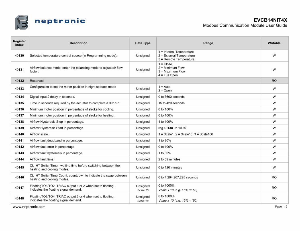
40130 Selected temperature control source (in Programming mode). Unsigned 1 = Internal Temperature 2 = External Temperature 3 = Remote Temperature
W
40131 Airflow balance mode, enter the balancing mode to adjust air flow factor.
Unsigned
1 = Close 2 = Minimum Flow 3 = Maximum Flow 4 = Full Open
W
40132 Reserved RO
40133 Configuration to set the motor position in night setback mode
Unsigned 1 = Auto 2 = Open
W
40134 Digital input 2 delay in seconds. Unsigned 0 to 3600 seconds W
40135 Time in seconds required by the actuator to complete a 90° run Unsigned 15 to 420 seconds W
40136 Minimum motor position in percentage of stroke for cooling. Unsigned 0 to 100% W
40137 Minimum motor position in percentage of stroke for heating. Unsigned 0 to 100% W
40138 Airflow Hysteresis Stop in percentage. Unsigned 1 to 100% W
40139 Airflow Hysteresis Start in percentage. Unsigned reg 40138 to 100% W
40140 Airflow scale. Unsigned 1 = Scale1, 2 = Scale10, 3 = Scale100 W
40141 Airflow fault deadband in percentage. Unsigned 1 to 30% W
40142 Airflow fault error in percentage. Unsigned 0 to 100% W
40143 Airflow fault hysteresis in percentage. Unsigned 1 to 30% W
40144 Airflow fault time. Unsigned 2 to 59 minutes W
40145 CL_HT SwitchTimer, waiting time before switching between the heating and cooling modes.
Unsigned 0 to 120 minutes W
40146 CL_HT SwitchTimerCount, countdown to indicate the swap between heating and cooling modes.
Unsigned 0 to 4,294,967,295 seconds RO
40147 FloatingTO1/TO2, TRIAC output 1 or 2 when set to floating, indicates the floating signal demand.
Unsigned Scale 10
0 to 1000% Value x 10 (e.g. 15% =150)
RO
40148 FloatingTO3/TO4, TRIAC output 3 or 4 when set to floating, indicates the floating signal demand.
Unsigned Scale 10
0 to 1000% Value x 10 (e.g. 15% =150)
RO

EVCB14NIT4X Modbus Communication Module User Guide
www.neptronic.com Page | 13
Register Index
Description Data Type Range Writable
40149 TO1 Pulsing, TRIAC output 1 when set to Pulsed, indicates the pulse signal demand.
Unsigned Scale 10
0 to 1000% Value x 10 (e.g. 15% =150)
RO
40150 TO2 Pulsing, TRIAC output 2 when set to Pulsed, indicates the pulse signal demand.
Unsigned Scale 10
0 to 1000% Value x 10 (e.g. 15% =150)
RO
40151 TO3 Pulsing, TRIAC output 3 when set to Pulsed, indicates the pulse signal demand.
Unsigned Scale 10
0 to 1000% Value x 10 (e.g. 15% =150)
RO
40152 TO4 Pulsing, TRIAC output 4 when set to Pulsed, indicates the pulse signal demand.
Unsigned Scale 10
0 to 1000% Value x 10 (e.g. 15% =150)
RO
40153 Over heat status. Unsigned
1 = OverHeatNormal 2 = OverHeat1 3 = OverHeat2 4 = OverHeatAll
RO
40154 Configuration to override the motor position. Unsigned
1 = Auto 2 = Open 3 = Close 4 = AirFlowCoolMin 5 = AirFlowCoolMax
W
40155 Information displayed on the TRL. Unsigned
1 = Temp Demand 2 = Setpoint Demand 3 = Temp 4 = Setpoint 5 = Off
W
40156 Status of digital input 2.
Unsigned 0 = Open 1 = Close
RO
40157
Cfg_Input3 Minimum Reading, this setting represents the deadband of the pressure sensor in mV.
Unsigned 10 to 180 mV W
40158 Minimum voltage of the external actuator’s control signal. Unsigned Scale 100
Range: 0 to reg. 400159 Value x 100 (e.g. 2 Volts = 200)
W

EVCB14NIT4X Modbus Communication Module User Guide
www.neptronic.com Page | 14
Register Index
Description Data Type Range Writable
40159 Maximum voltage of the external actuator’s control signal. Unsigned Scale 100
Range: reg. 400158 to 1000 Value x 100 (e.g. 10 Volts = 1000)
W
40160 Minimum voltage of the external actuator’s feedback signal.
Unsigned Scale 100
Range: 0 to reg. 400161 Value x 100 (e.g. 2 Volts = 200)
W
40161 Maximum voltage of the external actuator’s feedback signal. Unsigned Scale 100
Range: reg. 400160 to 1000 Value x 100 (e.g. 10 Volts = 1000)
W

Notes
400 Lebeau blvd, Montreal, Qc, H4N 1R6, Canada neptronic.com
Toll free in North America: 1-800-361-2308
Tel.: (514) 333-1433 Fax: (514) 333-3163
Customer service fax: (514) 333-1091 Monday to Friday: 8:00am to 5:00pm (Eastern time)