fabrication of fiber metal laminated …etd.lib.metu.edu.tr/upload/12618235/index.pdf ·...
TRANSCRIPT
FABRICATION OF FIBER METAL LAMINATED COMPOSITES BY RESIN
INFUSION TECHNIQUE USING METALLIC LAYERS WITH MODIFIED
SURFACE
A THESIS SUBMITTED TO
THE GRADUATE SCHOOL OF NATURAL AND APPLIED SCIENCES
OF
MIDDLE EAST TECHNICAL UNIVERSITY
BY
GÜNEY DALOĞLU
IN PARTIAL FULFILLMENT OF THE REQUIREMENTS
FOR
THE DEGREE OF MASTER OF SCICENCE
IN
METALLURGICAL AND MATERIALS ENGINEERING
NOVEMBER 2014

Approval of the thesis:
FABRICATION OF FIBER METAL LAMINATED COMPOSITES BY RESIN
INFUSION TECHNIQUE USING METALLIC LAYERS WITH MODIFIED
SURFACE
submitted by GUNEY DALOĞLU in partial fulfillment of the requirements for the
degree of Master of Science in Metallurgical and Materials Engineering
Department, Middle East Technical University by,
Prof. Dr. Gülbin Dural Ünver ________________
Dean, Graduate School of Natural and Applied Sciences
Prof. Dr. Cemil Hakan Gür ________________
Head of Department, Metallurgical and Materials Eng.
Assoc. Prof. Dr. Arcan F. Dericioğlu ________________
Supervisor, Metallurgical and Materials Eng. Dept., METU
Prof. Dr. A. Şakir Bor ________________
Co-Supervisor, Metallurgical and Materials Eng. Dept., METU
Examining Committee Members:
Prof. Dr. Cemil Hakan Gür _____________________
Metallurgical and Materials Eng. Dept., METU
Assoc. Prof. Dr. Arcan F. Dericioğlu _____________________
Metallurgical and Materials Eng. Dept., METU
Prof. Dr. A. Şakir Bor _____________________
Metallurgical and Materials Eng. Dept., METU
Prof. Dr. Cevdet Kaynak _____________________
Metallurgical and Materials Eng. Dept., METU
Assoc. Prof. Dr. Demirkan Çöker _____________________
Aerospace Eng. Dept., METU
Date: 21.11.2014

iv
I hereby declare that all information in this document has been obtained and
presented in accordance with academic rules and ethical conduct. I also declare
that, as required by these rules and conduct, I have fully cited and referenced all
material and results that are not original to this work.
Name, Last name: Güney Daloğlu
Signature :

v
ABSTRACT
FABRICATION OF FIBER METAL LAMINATED COMPOSITES BY RESIN
INFUSION TECHNIQUE USING METALLIC LAYERS WITH MODIFIED
SURFACE
Daloğlu, Güney
MSc, Department of Metallurgical and Materials Engineering
Supervisor: Assoc. Prof. Dr. Arcan F. Dericioğlu
Co-Supervisor: Prof. Dr. A. Şakir BOR
November 2014, 105 pages
Fiber metal laminated composites are novel materials which have been developed in
the last few decades especially for fatigue prone areas within the aircrafts. They consist
of metals with modified surfaces and fiber reinforced polymer matrix composites.
Surface modification of metals carries importance because their bonding with fiber-
resin matrix needs interdisciplinary knowledge about interface engineering. Surface of
the metal substrates must be contaminant and moisture free and void content through
interfaces of the final composite must be as low as possible to reach the desired
mechanical strength. So, wetting of the liquid/resin and wettability capability of the
solid/metal surface must be optimized. Different surface modifications like etching,
anodizing, plasma spraying, laser texturing, silane or sol-gel etc. treatments are being
used solely or together by industry. Fiber metal laminated composites have been
investigated under the scope of etching-anodizing surface pretreatment with adhesive
primer and fabricated with prepreg-autoclave manufacturing technique which are
long-batch and expensive techniques while they are also hazardous.

vi
Within this study, surface treatments of aluminum 2024 T3 alloy based on sand paper
abrasion and γ-glycidoxytrimethoxy silane treatment and fabrication of the fiber metal
laminated composites by vacuum infusion manufacturing technique have been studied.
The stress-strain and load-displacement relations and interface on both sides of
composites have been investigated in relation with the surface roughness-contact
angle-spreading capability controlled by the surface treatments applied. Achieved
results have shown that vacuum infusion is a successful alternative technique for the
fabrication of fiber metal laminated composites.
Keywords: Fiber metal laminated composite, vacuum infusion, γ-
glycidoxytrimethoxy silane, 2024 T3 aluminum alloy, surface pretreatment,
roughness, contact angle, spreading.

vii
ÖZ
REÇİNE İNFÜZYONU TEKNİĞİ İLE YÜZEYİ MODİFİYE EDİLMİŞ METALİK
KATMANLAR KULLANILARAK FİBER-METAL KATMANLI KOMPOZİT
MALZEME ÜRETİMİ
Daloğlu, Güney
Yüksek Lisans, Metalurji ve Malzeme Mühendisliği Bölümü
Tez Yöneticisi: Doç. Dr. Arcan F. Dericioğlu
Ortak Tez Yöneticisi: Prof. Dr. A. Şakir BOR
Kasım 2014, 105 sayfa
Fiber metal katmanlı kompozit malzemeler, hava araçlarının yorulmaya hassas
bölgelerinde kullanılmak üzere son 20-30 yılda geliştirilen yeni malzemelerdir. Bu
lamine kompozitler yüzeyi uygun hale getirilmiş metallerle fiber takviyeli polimer
matrisli kompozitlerden meydana gelirler.
Bu malzemelerin üretiminde metallerin yüzey hazırlık işlemleri önem arz etmekte ve
farklı disiplinlere ait yüzey mühendislik bilgilerini gerekli kılmaktadır. Kullanılan
metallerin yüzeyleri kirlilikten ve nemden arındırılmış olmalı ve istenilen mekanik
dayancın sağlanabilmesi için nihai kompozit malzemede mevcut hava boşluğu miktarı
olabildiği kadar düşük olmalıdır. Dolayısı ile sıvının/reçinenin ıslatma kabiliyeti
yüksek, katı/metal yüzeyinin ıslanma kabiliyetinin uygun hale getirilmesi
gerekmektedir. Kimyasal aşındırma, anodize etme, plazma püskürtme, lazerli doku
oluşturma, silan ve/veya sol-jel vb. yöntemleri birlikte veya ayrı ayrı olarak endüstride
yüzey hazırlama işlemleri olarak uygulanmaktadır. Fiber-metal katmanlı kompozitler
kimyasal aşındırma-anodize etme ve yapıştırıcı ile prepregi otoklavlama gibi uzun-

viii
yorucu-pahalı olmalarının yanında çevreye de zararlı üretim yöntemleri ile üretilmiş
ve araştırmalar buna göre yapılmıştır.
Bu tez çalışmasında, 2024 T3 aluminyum alaşımının yüzeyinin hazırlığı zımparalama
ve γ-glycidoxytrimethoxy silan uygulamaları ile, fiber-metal kompozit üretimi ise
vakum infüzyon tekniği ile yapılmıştır. Gerilim-gerinim, yük-yer değiştirme ilişkileri
ve kompozitin her iki taraftaki arayüz özellikleri uygulanan yüzey hazırlık işlemleri
ile kontrol edilen yüzey pürüzlülüğü-temas açısı ve yayılma kabiliyetine bağlı olarak
incelenmiştir. Elde edilen sonuçlar, vakum infüzyon tekniğinin fiber metal katmanlı
kompozit malzemelerin üretimi için başarılı bir alternatif olduğunu ortaya koymuştur.
Anahtar Sözcükler: Fiber metal katmanlı kompozitler, vakum infüzyon, silan, 2024
T3 aluminyum alaşımı, yüzey ön hazırlığı, pürüzlülük, temas açısı, yayılma.

ix
For my son Kemal Demir and my wife Sena;
to my precious mom Mefharet and dad Cengiz,
my mother and father in law Nilüfer and Aydın,
my Fu-Ahu Meryem and Zo-Umut,
my brother in law Mehmet.

x
ACKNOWLEDGEMENTS
I am very grateful to my supervisor Assoc. Prof. Dr. Arcan F. Dericioğlu for his
friendship, guidance and support during this work, and his great attention and patience
on me from the beginning until the end of my graduation.
It is great pleasure to thank my co-supervisor Prof. Dr. Şakir Bor, Prof. Dr. Cevdet
Kaynak for his always smiling face, Prof. Dr. Ali Kalkanlı for the strength he gave me
all the time, Prof. Dr. Rıza Gürbüz and Prof. Dr. Bilgehan ÖGEL for joyful sailing
synergy.
I am very grateful to my laboratory colleagues Simge Tülbez, Sıla Atabay, Mert Güney
Bilgin, Özgür Hamat, Erkan Aşık, Bensu Tunca and especially to Aylin Güneş and
Assist. Prof. Dr. Halil İbrahim Yavuz for their support and friendship at every stage of
this work and my graduation.
I am very grateful to METU Metallurgical and Materials Engineering Department for
all the support provided during this study. I want to thank to Assist. Prof. Dr. Orhan
Akar/METU MEMS for his cooperation and help for optical profilometry study.
I want to thank to my family, for their great patience, not only during this work but
also at every stage of my life.

xi
TABLE OF CONTENTS
ABSTRACT ................................................................................................................. v
ÖZ .............................................................................................................................. vii
ACKNOWLEDGEMENTS ......................................................................................... x
TABLE OF CONTENTS ............................................................................................ xi
LIST OF TABLES .................................................................................................... xiv
LIST OF FIGURES ................................................................................................... xv
INTRODUCTION ....................................................................................................... 1
LITERATURE REVIEW............................................................................................. 7
2.1. Fiber Reinforced Plastics .................................................................................. 7
2.1.1. Glass Fibers ................................................................................................ 7
2.1.2. Carbon Fibers ............................................................................................. 7
2.1.3. Aramid Fibers ............................................................................................ 8
2.2. Fiber Reinforced Polymer Matrix Composites ................................................. 9
2.2.1. Resins: ........................................................................................................ 9
2.2.2. Fibers: ..................................................................................................... 9
2.3. Composite Manufacturing Processes ......................................................... 10
2.3.1. Hand Lay-Up ............................................................................................ 10
2.3.2 Prepreg Forming .................................................................................. 11
2.3.3. Vacuum Bagging .................................................................................. 12
2.3.4. Filament Winding .................................................................................... 12
2.4. Fiber Metal Laminates ................................................................................ 12
2.5. Surface Pretreatments .............................................................................. 17
2.5.4. Phosphoric-Sulphuric Acid Anodizing –PSAA ................................... 20
xii
2.5.5. Sulphuric Acid Anodizing .................................................................... 21
2.5.6. AC Anodizing ...................................................................................... 21
2.5.7. Coupling Agents ................................................................................... 21
2.5.8. Mechanical Surface Treatments of Aluminum ........................................ 23
2.5.9. Chemical Etching of Aluminum Surface ................................................. 23
2.6. Fracture Analysis ..................................................................................... 24
2.7. Wetting Analysis ......................................................................................... 36
EXPERIMENTAL PROCEDURE ............................................................................ 47
3.1. Materials .......................................................................................................... 47
3.1.1. Resin ......................................................................................................... 49
3.1.2. Resin Hardener ......................................................................................... 49
3.1.3. Sealing Tape ............................................................................................. 50
3.1.4. Vacuum Bag ............................................................................................. 51
3.1.5. Mold Releasing Paste ............................................................................... 51
3.1.6. Aluminum 2024 T3 Alloy ........................................................................ 52
3.1.7. Glass Fiber ................................................................................................ 53
3.1.8. Silane Coupling Agent ................................................................................. 53
3.1.9. Sand Paper ................................................................................................ 54
3.1.10. Pure Water, Ethanol, Toluene ................................................................ 55
3.1.11. Peel Ply ................................................................................................... 55
3.1.12. Perforated ............................................................................................... 56
3.1.13. Breather and Flow Mesh ........................................................................ 57
3.1.14. Vacuum Pump ........................................................................................ 57
3.1.15. Hoses: Normal-Scratched ....................................................................... 57
3.1.16. Brass Tri-Gate Junctions ........................................................................ 58
3.2. General Procedure ........................................................................................... 58

xiii
3.3. Sample Preparation ......................................................................................... 59
3.3.1. Aluminum Layer Preparation ................................................................... 59
3.3.2. Resin Infusion Preparation ....................................................................... 65
RESULTS AND DISCUSSION ................................................................................ 73
4.1. SEM Analysis of Samples ............................................................................... 73
4.2. Contact Angle Measurement ........................................................................... 74
4.3. Roughness Measurement ................................................................................ 77
CONCLUSIONS ........................................................................................................ 95

xiv
LIST OF TABLES
TABLES
Table 2.1. Summary of Surface Treatments on Aluminum Alloys ........................... 19
Table 2.2. Tensile properties of 3 different orientation of fibers. ............................. 25
Table 2.3. Flexure properties of 3 different orientation ............................................ 25
Table 2.4. Typical Compressive Properties of Glare® Laminates ............................. 26
Table 2.5. Applied property parameters of all constituents in Glare® laminates for
prediction .................................................................................................................... 32
Table 2.6. Post impact fatigue test results of Glare® ................................................. 36
Table 4.1. Calculated spreading coefficients of surfaces treated with different
methods. ..................................................................................................................... 83
Table 4.2 Roughness Factor ...................................................................................... 85
xv
LIST OF FIGURES
FIGURES
Figure 2.1. Glare® areas in Airbus A-380. ................................................................ 13
Figure 2.2. The crack growth behavior of unidirectional Glare® 2, Cross plied
Glare® 3, Arall® 2 and 2024 T3 for a fuselage loading .............................................. 14
Figure 2.3. Schematic ARALL® arrangement .......................................................... 15
Figure 2.4. CRACK bridging .................................................................................... 16
Figure 2.5. Fatigue life of Glare® ............................................................................. 17
Figure. 2.6. Adhesive Bonding Interface .................................................................. 18
Figure 2.7. Typical sol-gel thin film representation .................................................. 22
Figure 2.8. Typical fracture pattern for Glare® Laminates Under Static Tensile
Loading ..................................................................................................................... 26
Figure 2.9. Stress-Strain Curves for Glare®4-3/2 under uniaxial tensile loading (a)
longitudinal; (b) transverse ........................................................................................ 28
Figure 2.10. The Fatigue Behaviour Of Glare® (a) Fatigue Crack Growth Behaviour
of Glare® for a fuselage loading; (b) a Schematic of Fatigue-Crack Mechanism ...... 33
Figure 2.11. (a)(b) Normalised Stiffness Properties of graphite epoxy laminates as a
function of crack density (c)(d) Strain Energy Release Rate for matrix cracking as a
function of crack density. ........................................................................................... 34
Figure 2.12. The impact behavior of glare® (a) Comparison of impact performance
of Glare® 3 and other aerospace materials; (b) Low velocity impact performance of
cross plied Glare® Laminates ..................................................................................... 35

xvi
Figure 2.13. Interface between adhesive and substrate (a) contaminant and void free,
(b) contaminated. ........................................................................................................ 37
Figure 2.14. Different types of contact angles .......................................................... 38
Figure 2.15.Displacemnet of triple line point. ........................................................... 39
Figure 2.16. Advancing and receding contact angle versus roughness ..................... 42
Figure 2.17. triple line point through grooves ........................................................... 43
Figure 2.18. Capillary pressure identification in a small pour .................................. 45
Figure 3.1. Typical resin infusion set-up ................................................................... 47
Figure 3.2. Resin and hardener used in this study ..................................................... 50
Figure 3.3. Sealant tape used in this study ................................................................ 50
Figure 3.4. Vacuum used in this study. ..................................................................... 51
Figure 3.5. Releasing paste used in this study. .......................................................... 52
Figure 3.6. 2024 T3 Aluminum alloy sheets used in this study. ............................... 52
Figure 3.7. Glass fiber woven fabrics used in this study ........................................... 53
Figure 3.8. Spraying of the prepared silane solution to the aluminum surfaces. ...... 54
Figure 3.9. Sand papers used in this study ................................................................ 55
Figure 3.10. Peel ply used in this study ..................................................................... 56
Figure 3.11. Perforated used in this study ................................................................. 56
Figure 3.12. Vacuum pump utilized in this study ..................................................... 57
Figure 3.13. Hoses: Scratched-Normal used in this study. ....................................... 58
Figure 3.14. Drilling of holes on 2024 T3 aluminum alloy. ..................................... 60
Figure 3.15 Hole (a) and groove (b) configurations on aluminum surfaces. ............ 61

xvii
Figure 3.16. X-ray photo of the fourth horizontal resin infusion sample containing
holes ........................................................................................................................... 62
Figure 3.17. Ultrasonic cleaning of aluminum substrates after sand paper abrasion 63
Figure 3.18. Silane treatment of aluminum substrates. ............................................. 64
Figure 3.19. Progress of resin infusion ..................................................................... 66
Figure 3.20. Fiber metal laminate composites sliced with micro cutter ................... 67
Figure 3.21. A wooden block has been used to prevent the damping of the blade. .. 68
Figure 3.22. Horizontal resin infusion sample containing holes as shown. .............. 69
Figure 3.23 . Horizontal resin infusion sample containing holes and 1.5 cm apart
grooves ....................................................................................................................... 70
Figure 4.1. 1000 sand paper treated aluminum surface before silane treatment. ...... 73
Figure 4.2. 1000 sand paper treated aluminum surface after silane treatment. ......... 74
Figure 4.3. As-received aluminum surface contact angle measurement image. ....... 75
Figure 4.4. Aluminum contact angle measurements for different surface
topographies......76
Figure 4.5. Average surface roughness values of different sand paper treatments. .. 77
Figure 4.6. a) Surface topography of 1000 sand paper and silane treated substrate
Optical profilometer display. b) Maximum height and depths of the substrate.
surface. ....................................................................................................................... 79
Figure 4.7. Surface data images of (a) 180 and (b) 1000 sand paper treated
surfaces........80
Figure 4.8. Surface tension measurement of the resin .............................................. 81
Figure 4.9. From a)Vertical and b)Horizontal views of fabricated samples ............. 85
xviii
Figure 4.10. Inter laminar shear stress values of the fiber metal laminated composite
samples ....................................................................................................................... 86
Figure 4.11. (a) Horizontal Resin Infusion-4. It can be seen that fracture occured in
the fiber- resin part of the composite, not at the interface on the aluminum side. (b)
The thin line observed shows the debonding between the aluminum and the fiber ... 89
Figure 4.12. Horizontal resin infusion-HV-1 sample showing mixed type fracture,
first from the fiber-resin composite than from the aluminum surface.. ..................... 90
Figure 4.13. a) Horizontal resin infusion sample-HVI-7, showed cohesiveness of
inter laminar shear stress against three-point bending test and did not show
delamination. b) Debonding between aluminum and fibers in 220 sand blasting and
phosphoric acid anodizing processed GLARE® ......................................................... 90
Figure 4.14. 1000 Sand Paper and Silane treated prepreg sample. ........................... 91
Figure 4.15. Vertical resin infusion sample-180 sand paper and silane treated. ....... 91
Figure 4.16. Stress-strain diagram of Airbus Standart-GLARE®. Area under the
curve shows the energy absorption capability ........................................................... 92
Figure 4.17. Stress – Strain diagrams of manufactured fiber metal laminated
composites.0.13 .......................................................................................................... 92
Figure.4.18. Variation of inter laminar shear strength as a function of strain rates for
different fiber metal laminated structures.ref.[60]………………………………. 114
1
CHAPTER 1
INTRODUCTION
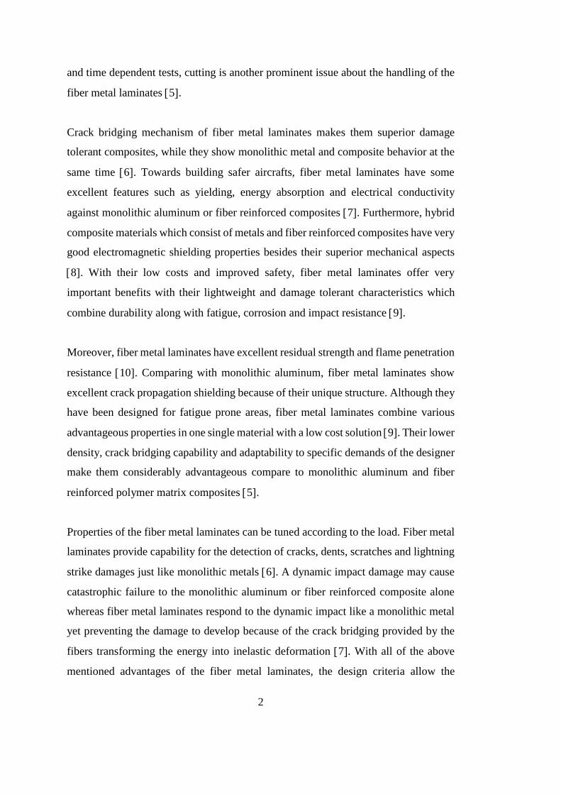
Modern aircraft design needs to investigate and reveal the fatigue cracks before they
reach the critical crack length so the structural materials must provide this tolerance
like fiber metal laminates (fail safe design criteria) 1. A permanent interest during
the last decades with newly emerging questions about fatigue resistant, high strength
and stiff materials have been satisfied by fiber metal laminates with their unique and
favorable properties 2. Fiber metal laminates are improved hybrid composites,
combining strong fibers with ductile aluminum layers, and show outstanding
properties with their being light weight 3.
Fiber metal laminates are the most emerging materials to be used as composites in
aviation industry because of their excellent fatigue and impact resistance,
machinability and formability properties along with their suitability for inspection
after impact 4. Fiber metal laminates combine the best properties of the matrix and
the fiber where they do not include the individual disadvantages of the two constituents
1. Fiber metal laminates have an important advantage over the conventional
composites being resistant to UV and moisture absorption, where they are superior
compared to monolithic aluminum in terms of their sensitivity to fatigue cracks.
Additionally, besides fabrication, quality control, plastic deformation, characterization
2
and time dependent tests, cutting is another prominent issue about the handling of the
fiber metal laminates 5.
Crack bridging mechanism of fiber metal laminates makes them superior damage
tolerant composites, while they show monolithic metal and composite behavior at the
same time 6. Towards building safer aircrafts, fiber metal laminates have some
excellent features such as yielding, energy absorption and electrical conductivity
against monolithic aluminum or fiber reinforced composites 7. Furthermore, hybrid
composite materials which consist of metals and fiber reinforced composites have very
good electromagnetic shielding properties besides their superior mechanical aspects
8. With their low costs and improved safety, fiber metal laminates offer very
important benefits with their lightweight and damage tolerant characteristics which
combine durability along with fatigue, corrosion and impact resistance 9.
Moreover, fiber metal laminates have excellent residual strength and flame penetration
resistance 10. Comparing with monolithic aluminum, fiber metal laminates show
excellent crack propagation shielding because of their unique structure. Although they
have been designed for fatigue prone areas, fiber metal laminates combine various
advantageous properties in one single material with a low cost solution 9. Their lower
density, crack bridging capability and adaptability to specific demands of the designer
make them considerably advantageous compare to monolithic aluminum and fiber
reinforced polymer matrix composites 5.
Properties of the fiber metal laminates can be tuned according to the load. Fiber metal
laminates provide capability for the detection of cracks, dents, scratches and lightning
strike damages just like monolithic metals 6. A dynamic impact damage may cause
catastrophic failure to the monolithic aluminum or fiber reinforced composite alone
whereas fiber metal laminates respond to the dynamic impact like a monolithic metal
yet preventing the damage to develop because of the crack bridging provided by the
fibers transforming the energy into inelastic deformation 7. With all of the above
mentioned advantages of the fiber metal laminates, the design criteria allow the

3
designers to accept fiber metal laminates as monolithic aluminum without the need for
some additional reinforcements 1.
Prepregs together with degreased-etched-anodized aluminum have been widely used
in aviation industry to fabricate fiber metal laminates utilizing high pressurized
autoclave for bonding 10. The autoclave manufacturing process is a long batch, and
expensive process restricting its own potential for automation 11. Autoclave-prepreg
system creates residual stress in the final component whose magnitude changes
according to the thickness of the material. Residual compressive stress in the fibers,
and tensile stress on the aluminum alloy render post stretching necessary resulting in
additional costs 1.
It is very hard to fabricate fine quality fiber metal laminated composite because the
manufacturing process is very complicated and difficult to control. Metal-prepreg,
prepreg-prepreg interfaces contain porosity which results in the inferior mechanical
properties of the final product because of poor adhesion 12. The prepreg materials
used with autoclave processes have high stiffness, as a result they cannot be shaped in
complex geometries. Because of these drawbacks automotive industry still cannot use
these materials under automation except for custom fabrications 11.
Vacuum infusion is a popular composite manufacturing technique. Compared to
prepreg-autoclave manufacturing, the consumables used in vacuum infusion have
higher shelf life, and there will be no need for large ovens, heat and pressure 11. In
industry vacuum infusion process has been used to handle large composite parts with
low costs making it the most popular in different industries like aviation,
transportation, marine and power units production. It is a composite manufacturing
technique requiring a low viscosity resin to wet a dry preform (fibers) under negative
pressure gradient 13. Another important property of vacuum infusion is its
applicability to complex shaped products. Composited fabricated by vacuum infusion
show better mechanical characteristics, consistency and repeatability than the ones
fabricated by hand lay-up or spraying techniques 13. In the near future, it is expected
4
that the industry will pay special attention to vacuum infusion, because it is feasible
against prepreg-autoclave process while it is also providing superior mechanical
performance compared to hand lay-up 11.
Joining is a key processing step in going from parts to components. Because riveting
or longitudinal lap joints create high stress concentration areas, adhesive bonding is
accepted to be a very efficient technique for joining aluminum structures 14.
Widespread scientific activities are ongoing about preparing surfaces properly for
adhesive bonding. Chromic acid anodizing process has widely been used on surface
pretreatment yet it has very important disadvantages as a result of which aerospace,
automotive and defense sectors are paying attention to replace it.
For long term service life of vehicles, good surface preparation carries importance for
adhesive bonding process. Surface pretreatment technologies being used for aluminum
alloys are not environmental friendly. There are some chemical etching processes like
chromic-sulfuric acid, Forest Product Laboratory (FPL) and sulpho-ferric acid etching
processes which are intermediate steps before anodizing processes. DC and AC
anodizing processes follow these etching processes to create passive porous oxide
layer, which are hazardous because they contain strong acids and hexavalent
chromium. Beside these hazardous chemicals, there are alternative surface
pretreatments involving environmental friendly coupling agents like silane and sol-gel
which must be developed for their applicability in industry 15.
The fiber-resin interfacial integrity provides the mechanical strength to the composite
structures 16. Insufficient adhesion because of porosity and void content leads to
stress concentration which creates delamination or cracks which have detrimental
effect on mechanical strength. Interface is the most important and central point to be
understood under interdisciplinary approach which creates a successful composite
with acceptable mechanical strength 12. Increasing the bonding strength of the
interface between the metal and the fiber reinforced composite plays an important role
on the durability of the final fiber metal laminate product 8.

5
Consequently, during the adhesive joining of aluminum structures special attention has
to be paid to the interfacial integrity and compatibility. In this scope, there must be
some primers to be used with Grid blast silane (GBS) treatment. A practical surface
pretreatment system must be developed for fiber metal laminates because the interface
determines the durability of the final composite. The main aim of intermediate
degreasing-anodizing-post treatment steps are to handle an uncontaminated and
roughened surface with stable oxide layer to increase the surface adhesion area 10.
Wetting optimization is the most important issue for the surface preparation. Practical
processes in the industries like aviation, automotive, high speed trains, armored
vehicles, naval architecture require spreading of a liquid on a solid which is affected
by the interfacial phenomena including thermodynamic wettability at equilibrium
state, contamination, hysteresis of the contact angle of the liquid on the solid,
roughness of the solid and spreading of the liquid over the solid 17. Interfacial
tensions of liquid and solid plays an important role on the wetting with capillary
origami and roughness where pressure gradients over them drive the fluid flow 18.
Good wettability of a substrate surface by a liquid or adhesive is vital for a sufficient
bond which constitutes the properties of both sides including surface wettability,
surface energy and spreading phenomena according to roughened topography 19.
Critical issues of wetting belonging directly to the nature of the solid and liquid surface
forces, dramatically change the bonding strength with their behavior to characterize
the bonding area chemically, thermodynamically or geometrically which include
contact angle-roughness relationship 20.
Fiber metal laminated composites have been fabricated with prepreg-autoclave
processes to combine the metal and the adhesive with fiber reinforced polymer matrix
composites until now. In addition to this, some experimental efforts have been
experienced about fabricating such materials using VARTM process. This study aims
to fabricate fiber metal laminated composites by vacuum infusion process and to
optimize the aluminum surface topography to reach to the mechanical characteristics
achieved in these materials by prepreg-autoclave processes. Vacuum infusion is

6
considered to be an alternative method for the fabrication of the fiber metal laminates
being low cost-easy labored process rather than the long-batch and expensive
processes of “etch-anodize-adhesive primer-prepreg-autoclave” including process
cycles.

7
CHAPTER 2
LITERATURE REVIEW
2.1. Fiber Reinforced Plastics
This definition is also referred as fiber reinforced polymer matrix composites which is
made of reinforcing materials as fibers, chips etc. and polymeric materials to surrender
the fiber dozens hold together and transferring the load to them 11. Thermoplastics
and thermosets are being widely used to as matrix materials. And as reinforcement
materials aramids, glass fibers, carbon fibers are being widely used which boron fibers,
metallic fibers etc. are beneath them.
2.1.1. Glass Fibers
Glass fibers can be classified as;
a) E-glass (improved electrical resistance)
b) S-glass (high strength)
c) C-glass (high chemical resistance).
2.1.2. Carbon Fibers
Carbon Fibers can be classified as;
a) Polyacrylonitrile (PAN) fibers,

8
b) Pitch or,
c) Rayon fibers through production processes.
Through heating, raw material loses most non-carbon atoms in the chain and
processing also aligns carbon chains with very high modulus (stiffness).
2.1.3. Aramid Fibers
Aramid fibers have the greatest strength and modulus properties of organic fibers and
Kevlar is the most commonly used aramid fiber. Aramids are strong and stiff but their
greatest value is in impact applications like;
a. Front side of airplane wings,
b. Armor applications.
After manufacturing the fiber they can be found from the market in the different forms
like; packages on spools called tows, chopped fibers (including whiskers), mat
(random),woven fibers, tapes and manufactured as prepreg.
Although they’ve got lower mechanical properties, the cost of glass fiber reinforced
composites create interest to build big-large components against carbon reinforced
composites to use under non-extreme weather conditions 21.
When we use the term composites during daily life, generally it’s understood that
we’re intending to talk about fiber reinforced-polymer matrix composites. We prefer
“daily life” saying because composite materials occupied lots of materials’ place in the
recent decades and become mostly used preferential because of their specialties like;
strength with low weight – low cost for most applications except aerospace industries
etc., long term service capability, long term durability, their excellent fatigue strength,
damage tolerance, impact absorbance etc 11.

9
2.2. Fiber Reinforced Polymer Matrix Composites
Manufacturing processes and used materials to manufacture composites differentiate.
If it’s tended to classify the materials that being used in fiber reinforced polymer matrix
composites and manufacturing from a general scope the details below can be specified.
2.2.1. Resins:
Thermoplastic resins which are generally used with short fibers, while thermoset resins
those can be used with long fibers, which are preferential because of strength but got
an issue about being environmentally friend consumable that must be developed
because of recycling problems 13.
Resin as matrix decides the outer performance of the composites against thermal
resistance, fire resistance, proper surface condition and photooxidation resistance 11.
2.2.2. Fibers:
Short fibers which are less than 0.2 inches (whiskers), which are being processed
through standard thermoplastic processes, while the final product must pass through
gates, runners, and gaps between processing screw and barrel walls. Intermediate
length fiber reinforcements which are longer than whiskers, carry difficulties to coat
them enough to reap strength benefits, low viscosity thermosets to “wet-out” the
materials better than high viscosity thermoplastics and generally used with unsaturated
polyester and vinyl ester resins. Continuous fibers, which are well known as very long
fibers, are being typically used with thermosets, used generally in advanced composite
parts and have greater material property requirements. If we tend to classify the
manufacturing methods;
Thermoplastic processes –Very short fibers
Matched die/compression molding

10
RTM
Spray-up
Hand lay-up for wet and prepreg materials
Filament winding and fiber placement
Pultrusion
VARTM-Vacuum Assisted Resin Transfer Moulding
VAP-Vacuum Assisted Processing.
2.3. Composite Manufacturing Processes
Brief explanations will be given here about the most important composite
manufacturing processes.
2.3.1. Hand Lay-Up
Hand (wet) lay-up consists of placing the preform on the mold and then applying resin
by brush or roller or spray. This is the cheapest way of any composite manufacturing
method 11.
In the marine industry, where enormous parts are being produced hand lay-up process
is the most widely used fabricating technique 22.
Only one smooth surface is achieved, controlling the volume fraction of the fiber and
the resin and the thickness according to these is severely limited. Typical advantages
of hand lay-up processes are low cost tools and versatile: wide range of products. And
the disadvantages are time consuming, unhealthy situation for the labor because of the
hazardous gases that resins release, easy to form air bubbles and disorientation of fibers
which can create inconsistency and decrease the mechanical strength severely.

11
2.3.2 Prepreg Forming
No other composites processing method has yielded the properties and repeatability as
high as autoclaving of prepreg materials 11.
For most aerospace applications, prepreg is the preferential method because of its’ high
mechanical strength according to low void content and optimum resin volume.
Pre-impregnated is the source of the word “Prepreg”. During prepreg’s manufacturing
process, the resin is being separated to the fabric with high pressure and partially cured
to keep its bonded situation.
A manufacturer who is using prepreg must put it on a mold (Figure 2.2) and complete
the curing under the temperature and pressure needed. There are autoclave oven
assemblies with high pressure and heat to step up to the curing and finishing parts and
the process can be made automated if preferred 23.
The autoclaves are very important devices to handle the best mechanical properties
with optimum volume fractions of fiber and the resin. Because of the impregnation
phenomena during the production step of prepreg itself, void content between fiber
and the resin decreases under 2% which makes the prepreg forming preferential for
aerospace industry with its high strength/weight ratio 24.
Although its excellent properties, prepreg has got some disadvantages like high cost,
short shelf life, supplying conditions that necessitate controllable temperature and
moisture conditions 11.
Also it’s not so easy to fabricate complex shapes with prepreg because of its’ being
partially cured-which makes the material stiff. The manufacturer who uses prepreg
must concern after every sheet lay up to pressurize the mold and control implementing
void, delamination or not.
Fabricating the GLARE® with prepreg in autoclave makes the production step very
expensive and has got constraint in dimensions 25.

12
2.3.3. Vacuum Bagging
Vacuum bag molding, a refinement of hand lay-up, uses a vacuum to eliminate
entrapped air to decrease the void content and excess resin. Until the resin cured the
vacuum bag keeps the mold insulated from air. The pressure difference between the
mold and the atmospheric pressure outside of the mold, a kind of clamping would be
forced to the composite inside so better and sophisticated parts can be manufactured.
Vacuum bagging has got a simple design with any fiber/matrix combination which has
better quality for the cost. At the same time, it depends to the labor to handle the
consistency desired. During vacuum bagging, heating up is limited so moisture can
captured to the mold and can be slow 26.
2.3.4. Filament Winding
Filament winding consists of winding continuous roving of fiber onto a rotating male
mandrel in predetermined patterns to product compressed air tanks, sail boat masts,
light poles, high pressure tanks of CO2 etc 27.With this process, many different
fibers and resins can be used to achieve desired characteristics for the finished
component. This method of manufacturing composites provides good control over
fiber placement through uniformity of the structure but optimizations are still being
developed numerically 28.Parts with huge sizes can be fabricated by filament
winding process but shape of the product and heat treatment after fiber placement can
push the manufacturer to spend afford and additional money.
2.4. Fiber Metal Laminates
Fiber metal laminates are composites that are brought together to get the best
properties of each metal and fibers which united with a resin. Fiber metal laminates
combine the best properties of each material that consist them 28.
Fiber metal laminates with their low weight, they’ve got very good fatigue, impact
properties with fire and corrosion resistance 30. Fiber metal laminates carry the

13
outmost properties of the material that are being composed which are thin metal sheets
and the composites 25. Multiple metal plies that are laminated with adhesives
increases the fracture toughness of monolithic aluminum with the same thickness 31.
Fatigue behavior and crack impeding properties in fiber metal laminates are better than
monolithic aluminum 32. Damage tolerance of laminated titanium is better than
monolithic titanium at the same thickness 33.
GLARE® is glass fiber reinforced laminate for advanced aircraft structures which
carries the properties like outstanding fatigue resistance, flame retardance with burn
through resistance, excellent impact resistivity, residual strength, blunt notch
resistivity, good corrosion resistance, good damping, insulation and easy repairment
availability30.
Figure 2.1. Glare® areas in Airbus A-380.0.130.
Between others lower density, crack bridging of the fibers –which creates excellent
fatigue resistance-, tailoring against mechanic demands by orientation of the fibers can
be told mechanically advantageous compared to monolithic aluminum 5. Fiber metal

14
laminates give capability to inspection just like metals which decrease the costs
because of increasing the inspection periods 29.
In the last three decades fiber metal laminates are the emerging new fuselage and wing
materials because of their excellent fatigue (shown in fig.1), damage tolerant, impact
resistant and flame retardant properties with low inspection intervals, repairment
feasibility -with different techniques which increases damage tolerant nature and blunt
notch strength of these materials over monolithic 2024 T3 aluminum layers according
to complex failure modes 9.
Figure 2.2. The crack growth behavior of unidirectional Glare® 2, Cross plied Glare®
3, Arall® 2 and 2024 T3 for a fuselage loading 30.0.2
Fiber metal laminates show good durability against thermal fluctuations and are stable
in cryogenic environments. There have been investigated fiber metal laminates for
decades to use in the aerospace industry with different kinds and with different
materials like ARALL®, CARALL® and GLARE®.

15
ARALL® carries the meaning aramid reinforced aluminum laminate, which tried to be
specified from 1980s to use in the wings of the airplanes.
Figure 2.3. Schematic ARALL® arrangement34..0.3
ARALL® is the first metal laminate and it’s discovered and seen later that under
compressive loads aramid fibers response very bad 34.
CARALL® that has the meaning carbon fiber reinforced aluminum laminate
developed and at the beginning of the 1990s, GLARE® which means glass fiber
reinforced aluminum laminate has been developed to use in the airplanes for civil
transportation.
GLARE® can be compared to aluminum monolithic sheet and if the advantages must
be said it must start with the low density with excellent fatigue behavior according to
fiber bridging of the fiber and the materials’ giving ability to be tailored fort the design
values of the strength in the area that wanted to be carried by the orientation and the
arrangement of the fiber 5. Because of better compressive behavior of glass,
GLARE® has been developed in 1991 35.

16
Aramid is the fiber which has got the highest strength in composites but at the same
time has got an disadvantage that is very important for a flying vehicle: it’s heavy.
After trials in some special parts like doors etc. lighter but similar load carrying carbon
fibers are tried for the applications. But carbon with its all strength has poor ductility.
Because of its high stiffness shaping and tailoring the CARALL® is not so easy.
From the fatigue point of view GLARE® gives an advantage with its fiber bridging
capability when a crack starts to propagate and because of its load transferability it
increases the design stress values while it decrease the crack propagation speed.
(fig.2.9)When a fatigue crack nucleates and starts to propagate fibers are partly
banning and slowing the propagation but these phenomena promotes a shear load
between fiber and the aluminum sheet. According to this shear load occurrence,
thinning the aluminum sheet while increasing the number of the aluminum sheets to
handle the same fiber metal laminate thickness, small fatigue cracks will be carried
and banned by the GLARE® with its separating the shear loads to concentrate at
smaller parts-smaller delamination 5.
Figure 2.4. CRACK bridging 5.0.4

17
For monolithic aluminum, it is very easy to inspect and consider the damage because
its being visible on the sheet therefore the damage size can be recorded and the
remaining life of the material with the residual strength may be calculated analytically.
Figure 2.5. Fatigue life of Glare® 5, 36 0.5
The impact damage detection and the chase of the damage is the same for GLARE®
with the monolithic aluminum but GLARE® has a real advantage because of fiber
crack bridging which bans/slows the propagation and carries significant loads. But in
an unexpected-not followed-incident situation R-curve approach can be approximated
to the GLARE® just like monolithic aluminum 6.
From the machining and bending point of view, the GLARE® is being accepted as a
metal in the literature and the acceptance criteria of the airworthiness directives. To
machine and to bend the glare® is possible -which is not for normal composites-so
glare® can be accepted as a metallic structure 5.
2.5. Surface Pretreatments
Surface treatments must be tailored excellent to get the long term service life for
adhesive bonding applications for the aerospace industry 15.

18
Low joint strength, failure modes of fracture, delamination during adhesion or after
loading emerge up to decreased strength of adhesion. Before the surface treatment
some issues must be under control to get the best result of adhesion like; contamination
free area, mechanical stability, roughness optimization, wettability with the chemical
used during the process and hydrolytically stability 37.
Additionally, void content of interface in the adhesion zone, authorize the strength of
adhesion, which creates a crack nucleation point except contamination creates a stress
concentration. Proper roughness must be attended to increase the surface area of
adhesion. Moisture and thermal exposure creates hydrothermal aging which promotes
failure of adhesion by nucleation of fracture at the entanglement of small
delaminations under mixed modes of loads during exposure 38.. Hydrolytically
stabilized interface will be dominant for long service time against delamination of
moisture failure. The most important issue to understand the failure mechanisms of
adhesion is the interface zone between organic and the inorganic materials as shown
in Fig. 1 15
Figure. 2.6. Adhesive Bonding Interface 15.Figure 6
0.7

19
There are several surface treatments to modify, optimize and/or prepare the aluminum
surface for proper adhesion, which are summarized in Table 2.1.
Table 1
Table 2.1. Summary of Surface Treatments on Aluminum Alloys 15.
Aerospace industry prefer to use the anodizing methods, which has been used for
nearly fifty years, just because it gives dependability with it’s been experienced
widely. However, all R&D activities about the hybrid composites/metal-organic
compound material researches around the world, struggles to find out to not to use the
chemicals that are hazardous and does not response for recycling which contain
hexavalent chromium, strong acids etc. with chromic acid anodizing, phosphoric acid
anodizing etc. A brief knowledge will be given about several surface treatments in this
chapter.

20
2.5.1. Electrochemical Surface Treatments
Chromic Acid Anodizing and Phosphoric Acid Anodizing are widely used
electrochemical processes in different unions and districts of aerospace industry.
Experiments showed that these anodizing types were preferred to bond the metallic
parts, but hazardous materials like strong acid and hexavalent chromium are being
used during these processes 15.
Limitations of hazardous chemicals of these methods is the driving force for attending
to find out other proper solutions with the same strength, durability and porosity
needed.
2.5.2. Chromic Acid Anodizing-CAA
In this type of anodic process, first current with the same level of at 40 volts DC
followed by a second level at 50 volts DC as would be enough 39. CAA process
which has been used in European aerospace industry creates thicker and more
amorphous surface layer than phosphoric acid anodizing.
2.5.3. Phosphoric Acid Anodizing-PAA
PAA is currently the preferred anodizing option for primary bonded structures in the
United States. The PAA-processed area of the sample gives possibility to good
capillary forces on the chemical and/or adhesive, so there will be strong enough
interlocking to create a good adhesion 40. PAA gives better durability than CAA
but static strength of lap shear tests are similar.
2.5.4. Phosphoric-Sulphuric Acid Anodizing –PSAA
The PSAA process was developed by DaimlerChrysler Aerospace Airbus which does
not include hazardous chemicals like chromic acids. The process is simple it is
giving the industry motivation to use with its reliability 41.

21
2.5.5. Sulphuric Acid Anodizing
Sulphuric Acid Anodizing gives really good results for protective coating and painting,
and giving an opportunity to create wide scale of oxide thicknesses on aluminum alloys
15
2.5.6. AC Anodizing
SINTEF Materials Technology and Norwegian University of Science and Technology
develops AC anodizing process which is different on the main practice from the other
anodizing processes 42.
This alternative is a highly feasible, robust, and environmentally friendly process,
which is free from the hexavalent chromium found in the conventional CAA. The main
differentiation of AC anodizing from DC anodizing is hydrogen gas is being produced
by the surface of the sample which eliminates the contamination near anodizing.
2.5.7. Coupling Agents
During the last decades environmental friendly coupling agents are being optimised to
use like silane, sol-gel etc.
2.5.7.1. Silane
Silane is going to be explained in detail with its application method later in this thesis.
But to give a brief information about silane the thickness and the chemical bonding
type of it must be emphasized near its environmental friendly structure.
Aqueous γ-glycidoxypropyltrimethoxy silane (γ-GPS) solution has got between 1.5-
2.9 nm. This coupling agent is making the bond between the oxide of the metal
substrate and the organic compound of the resin with its propyl chain. Thousands of

22
adhesively bonded repairs using silane techniques have been applied to military
aircrafts over the past 25 years 15.
Rider and Arnott 43. gave descriptions about the silane treated surface are being
hydrolytically stable and strengthens the bonding interface, increases the durability.
Abel et al. 44., showed whit time of flight secondary ion mass spectrometry, well
bonded Al-O-Si couple experienced between silane solution of γ-GPS and aluminum
substrate. The crack growth was propagated through the interface (‘‘composite-zone’’)
between oxide, silane, and adhesive in cohesive failure mode, which is considered as
an optimum type of failure that occurs primarily in the adhesive layer 15.
2.5.7.2. Sol-Gel
Another option, i.e., sol-gel, a contraction for solution- gelation, which involves the
growth of metal-oxo polymers through both hydrolysis and a condensation reaction to
form inorganic polymer networks in thicknesses ranging from 50 to 200nm.
Figure 2.7. Typical sol-gel thin film representation 15. 0.1

23
Instead of these conventional wet chemical processes, dry surface treatments like
excimer laser texturing, plasma sprayed coating and/or ion beam enhanced film
deposition techniques can be used. E of hazardous chemical processes but they must
be optimized for the strength and the durability with the cost feasibility.
2.5.8. Mechanical Surface Treatments of Aluminum
Mechanical abrasion is the preliminary step for cleaning the hazardous oxide layer and
to get a optimized rough surface 15.
It is being achieved by abrasion with sand paper, special pads by hand/machines or
stood for alumina grids with sand blasting. Mechanical surface treatments create a
surface activation which establishes macro roughness before other surface treatments
like silane, sol-gel, plasma oxidation etc.
2.5.9. Chemical Etching of Aluminum Surface
Chemical treatment is an intermediate preparation between removing the
contamination, cleaning with some chemicals like MEK, toluene etc., and electro-
chemical process. Chemical etching should be in accordance with the fore-treatments,
i.e., an anodizing process 15.
Different companies in different countries prefer different methods of chemical
treatments like FPL-Forest Product Laboratory dichromate sulphuric etching, CAE-
Chromic Acid etching and sulpho pherric etch.
Some airworthiness directives and/or journals have been declared that adhesive
bonding after FPL method has got serious issues to solve about durable bonding. After
all, the FPL process that dichromate-sulphuric acid is being used during it, still is a
common and widely used process to handle chemical etching with 40 nm passivized
oxide layer by the aerospace industry 37.

24
To replace FPL that uses very hazardous chemical-sulphuric dichromate- sulpho-
pherric chemical treatment is being used which has been called P2 process too 45.
P2 creates thinner oxide layer than FPL, which is like 37 nm.
These chemical treatments which modify the surface of the substrate are not suitable
to use as stand-alone but intermediate step before anodizing.
2.6. Fracture Analysis
GLARE® is glass fiber reinforced laminate for advanced aircraft structures which
carries the properties like outstanding fatigue resistance, flame retardance with burn
through resistance, excellent impact resistivity, residual strength, blunt notch
resistivity, good corrosion resistance, good damping, insulation and easy repairment
availability.
Fiber metal laminates shows excellent properties of both metal sheets and fibers while
impeding or catching crack with perfect damage tolerant and impact resistant
structures of them even though they got low density. Through thickness corrosion
resistance response is much better than monolithic aluminum. Aluminum layer
prevents the material from UV and moisture, if the moisture goes in from the first
layer/outer layer of the aluminum-first layer of glass fiber capture it so prevents the
rest of the fiber metal laminate from moisture 46.
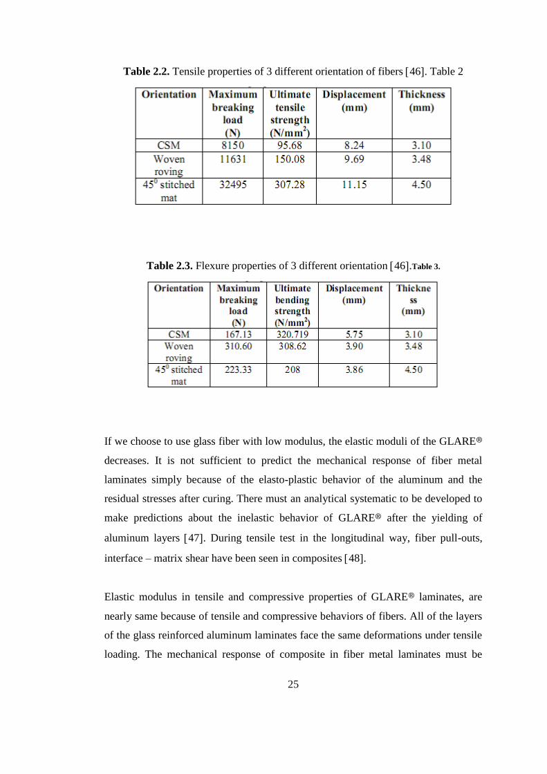
The tensile properties of unidirectional GLARE® shows better results and transverse
GLARE® shows lower results from longitudinal monolithic aluminum.
High strength glass fibers give to the glare® higher tensile strength, compressive
strength and adhesive ability relative to aramid fibers because glass fiber offers good
cross-ply orientation. Volume fraction of the orientation of fiber determines the tensile
and flexural strength of glare® laminates and for tensile loads 45 degrees stitched mat
and for flexural strength woven roving had greater properties.(fig.2.14)
25
Table 2.2. Tensile properties of 3 different orientation of fibers 46. Table 2
Table 2.3. Flexure properties of 3 different orientation 46.Table 3.
If we choose to use glass fiber with low modulus, the elastic moduli of the GLARE®
decreases. It is not sufficient to predict the mechanical response of fiber metal
laminates simply because of the elasto-plastic behavior of the aluminum and the
residual stresses after curing. There must an analytical systematic to be developed to
make predictions about the inelastic behavior of GLARE® after the yielding of
aluminum layers 47. During tensile test in the longitudinal way, fiber pull-outs,
interface – matrix shear have been seen in composites 48.
Elastic modulus in tensile and compressive properties of GLARE® laminates, are
nearly same because of tensile and compressive behaviors of fibers. All of the layers
of the glass reinforced aluminum laminates face the same deformations under tensile
loading. The mechanical response of composite in fiber metal laminates must be

26
accepted linearly elastic. Because of aluminum shows plastic response for a very long
time after yield point, total fiber metal laminate shows nonlinear tensile behavior and
an approximation that accepts normal stress-strain relation does not give adequate
results 30.
If the notch size gets bigger, the blunt notch resistance increases in GLARE® due to
the static delamination of fiber reinforced composite which levels off the stress and
delay fiber fracture in/near the hole.
The compressive yield strength of GLARE® is lower than tensile yield strength but
because of their good response to compressive loads in the longitudinal orientation of
fibers, fiber metal laminates are not being used for only tensile properties of them
except aramid reinforced fiber metal laminates which response with micro buckling
against compression 2.
Table 2.4. Typical Compressive Properties of Glare® Laminates30.Table 4
0.1
Because of the elasto-plastic behavior of the aluminum composite part of the Glare®
faces a catastrophic failure under tensile loads an example of which is shown in Figure
2.8. At first part both materials, aluminum and the composite, responses with their
young’s modulus and after 250 MPa Aluminum starts to plastically deform so the
incline decreased but the fiber metal laminates showed good resistance by the linear
elastic response of the composite inside. (Figure 2.9)

27
Figure 2.8. Typical fracture pattern for Glare® Laminates Under Static Tensile
Loading 3.
Very limited data has been published about crack opening behavior of GLARE®
laminates.
An analytical modeling includes in-plane forces, moment results in the composite,
mid-plane strains and the curvature may seem like giving well results/almost the same
with the experimental results.

28
Figure 2.9. Stress-Strain Curves for Glare®4-3/2 under uniaxial tensile loading (a)
longitudinal; (b) transverse 30.2
By the classical lamination theory the relationship between the applied load and the
deformation can be defined as:
[�̅��̅�
] = [𝐴 𝐵𝐵 𝐷
] [𝜀0
𝑘] (1)
Where, [N]=[N]+[NT] and [M]=[M]+[MT] where N is in-plane force, M is moment
results per unit length, ε and k represent the mid-plane strains and curvature, and N
and M are thermal force and moment results per unit length respectively.
The resultant forces and moments are obtained by integration of the stresses in each
layer over the laminate thickness H;
[𝑁, 𝑀] = ∫ [𝜎𝑘](1, 𝑧)𝑑𝑧.−𝐻/2
−𝐻/2 (2)

29
The stress [σ]k in the kth ply at a distance z, at any distance of loading can now be
expressed as;
[
𝜎11
𝜎22
𝜎12
]
𝑘
= [𝑄11 𝑄12 0𝑄12 𝑄22 00 0 𝑄66
]
𝑘
{[
𝜀110
𝜀220
𝜀120
] + 𝑧 [𝐾11
𝐾22
𝐾12
] − [
𝛼11
𝛼22
𝛼12
] ∆𝑇}, (3)
Where Qij is the reduced stiffness matrix, αij is the ply lamina coefficient of thermal
expansion in the principal material coordinate system and ΔT is the temperature
change during curing.
Under a uniaxial load, the deformation behavior of the laminate, as glare® has been
accepted that all layers experience the same deformations because of compatibility of
all of the layers, is described by the relation;
[dN]=[A][dε] (4)
Where dN is the increments of the in-plane force per unit length, dN=Hdσ and H is the
total thickness of the fiber metal laminate. The extensional stiffness matrix [A],
coupling stiffness matrix [B] and bending stiffness matrix [D] must be identified as;
And the extensional stiffness matrix [A] can be calculated as;
[A]= nA1[QA1]hA1+nc[Qc]hc (5)
Where the number and thickness of the aluminum layer and glass/epoxy composite
layer are expressed as nA1, hA1 and nc, hc respectively.
The composite in the glare® laminate can be accepted as linear elastic orthotrophic
material. Stress-strain relations according to increments are;
[dσc]=[Qc][ dεc] (6)

30
Where Qc is the reduced stiffness matrix of composite layers.
[𝑄𝑐] =
[
𝐸11𝑐
1−𝑣12𝑐 𝑣21
𝑐
−𝑣12𝑐 𝐸22
1−𝑣12𝑐 𝑣21
𝑐 0
−𝑣12𝑐 𝐸22
1−𝑣12𝑐 𝑣21
𝑐
𝐸22𝑐
1−𝑣12𝑐 𝑣21
𝑐 0
0 0 𝐺12𝑐 ]
(7)
After the point of yielding, aluminum shows great plasticity so, Glare® laminates show
nonlinear tensile response. To handle accurate elastic analysis for accurate prediction
of stress-strain relation; as using the 2024 T3 aluminum alloy is being taken as the
aluminum, the plastic flow potential for the plastic deformation of aluminum was taken
as;
fA1(σij)=1/2[b11(σ11)2+ (σ22)
2- σ11 σ22+3(σ12)2] (8)
The plastic strain increments (dεp)ij are belonged to the stresses by the potential flow
rule;
(dεp)ij=dλ(∂fA1/∂ σij) (9)
A power law relates the effective stress and the effective plastic strain; for A1
έp = φ(σ’)γ (10)
where the effective stress is defined as: σ’= (3f)1/2
dλ=3/2. (dεp’/ σ’)=Ω(n1dσ11+ n2dσ22+ n3dσ33) (11)
where, Ω=(9/4). Φγ. (σ’)γ-3, n1=0,5(2b11σ11- σ22), n2=0,5(2σ22- σ11), n3=3 σ12 for
Al.
31
Combining the equation (11) with (8) and (9), the relations between plastic strain
increments and the stress increments are obtained;
[dεp]=[Sp][ dσ] for Al (12)
Where Sp are given by;
(Sp)11= Ω. n1 n1
(Sp)12= Ω. n1 n2
(Sp)16= Ω. n1 n3
(Sp)22= Ω. n2 n2 (13)
(Sp)26= Ω. n2 n3
(Sp)66= Ω. n3 n3
For the elastic part of the aluminum, the stress – strain relation is;
[dεe]=[Se][dσ]. (14)
Where Se;
[𝑆𝑒𝐴𝑙] =
[
1
𝐸𝐴𝑙
−𝑣𝐴𝑙
𝐸𝐴𝑙 0
−𝑣𝐴𝑙
𝐸𝐴𝑙
1
𝐸𝐴𝑙0
0 01
𝐺𝐴𝑙]
(15)
From the equations (12) and (16) we can get the total incremental stress-strain relation
of the aluminum layers;
[dε]= [dεe]+ [dεp]=([Se]+[Sp])[dσ]. (16)
So for the aluminum;

32
[dσ]=[Q][dε], (17)
where
[Q]= ([Se]+[Sp])-1. (18)
When the equation (20) is combined with equations (5) and (4), a total incremental
constitutive relation is obtained:
[dN]=[ nA1hA1([Se]+[Sp])-1+nchc(Qc)] (19)
Now the equation (19) can be used to handle the stress – strain relationship of Glare®
laminate when combined with equations (15), (13), (7) and (3) 3.
Table 5
Table 2.5. Applied property parameters of all constituents in Glare® laminates for
prediction.
Stiffness and fracture analysis of composites/fiber metal laminates must depend on
different kinds of loadings, dynamic state, cracks in the resin which are parallel to the
reinforcement and in the off-axis ply is the beginning of the all interlaminar failures
49.
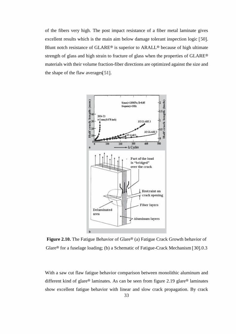
It can be seen that fatigue resistance of a fiber metal laminate with a fatigue crack
initiation is greater than a fiber metal laminate that has a saw cut due to the unbroken
fibers and narrower delamination zone around the crack which effects the strain length
33
of the fibers very high. The post impact resistance of a fiber metal laminate gives
excellent results which is the main aim below damage tolerant inspection logic 50.
Blunt notch resistance of GLARE® is superior to ARALL® because of high ultimate
strength of glass and high strain to fracture of glass when the properties of GLARE®
materials with their volume fraction-fiber directions are optimized against the size and
the shape of the flaw averages51.
Figure 2.10. The Fatigue Behavior of Glare® (a) Fatigue Crack Growth behavior of
Glare® for a fuselage loading; (b) a Schematic of Fatigue-Crack Mechanism 30.0.3
With a saw cut flaw fatigue behavior comparison between monolithic aluminum and
different kind of glare® laminates. As can be seen from figure 2.19 glare® laminates
show excellent fatigue behavior with linear and slow crack propagation. By crack
34
bridging a significant load is being carried by the fibers, stress intensity factor and the
crack growth rate in the aluminum layers are being decreased 52.
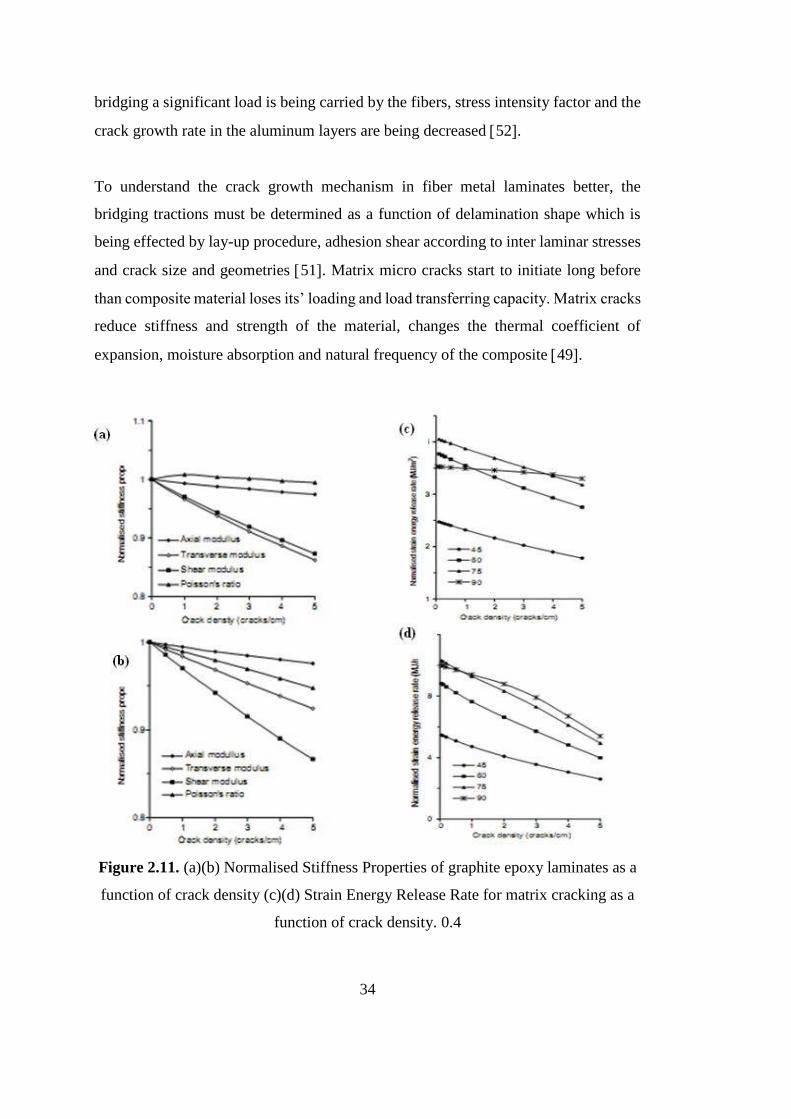
To understand the crack growth mechanism in fiber metal laminates better, the
bridging tractions must be determined as a function of delamination shape which is
being effected by lay-up procedure, adhesion shear according to inter laminar stresses
and crack size and geometries 51. Matrix micro cracks start to initiate long before
than composite material loses its’ loading and load transferring capacity. Matrix cracks
reduce stiffness and strength of the material, changes the thermal coefficient of
expansion, moisture absorption and natural frequency of the composite 49.
Figure 2.11. (a)(b) Normalised Stiffness Properties of graphite epoxy laminates as a
function of crack density (c)(d) Strain Energy Release Rate for matrix cracking as a
function of crack density. 0.4

35
High failure strain and high strain strengthening of fibers are giving to the glare®
highest performance about impact resistance.
Figure 2.12. The impact behavior of Glare® (a) Comparison of impact performance
of Glare® 3 and other aerospace materials; (b) Low velocity impact performance of
cross plied Glare® Laminates 30.0.5
At relatively low speeds of aircraft, impact tolerance of both monolithic aluminum and
the fiber metal laminates are the same but at the high speed levels because of the fibers’
strain hardening and the strain rate of aluminum, fiber metal laminates show extremely
better results.
After the impact, the damage can be seen as a dent on the aluminum layer of glare®
and there is a very small damage distributed in-plane of the fiber metal laminate
compared to the other composites. The “compaction after impact” test results are the
same with the monolithic aluminum and there is no buckling of delamination inside
the sandwich structure of the glare® which is very important for composites too.
36
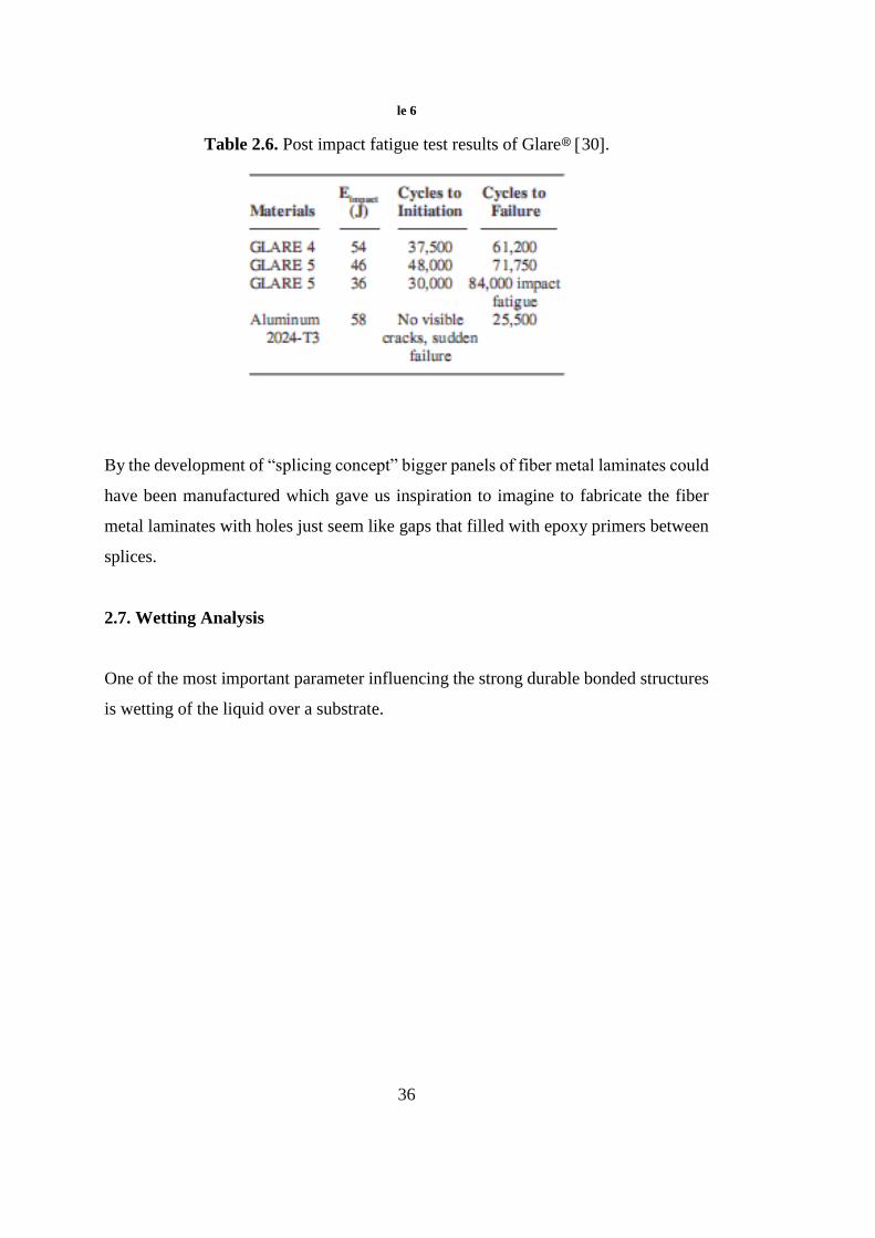
le 6
Table 2.6. Post impact fatigue test results of Glare® 30.
By the development of “splicing concept” bigger panels of fiber metal laminates could
have been manufactured which gave us inspiration to imagine to fabricate the fiber
metal laminates with holes just seem like gaps that filled with epoxy primers between
splices.
2.7. Wetting Analysis
One of the most important parameter influencing the strong durable bonded structures
is wetting of the liquid over a substrate.

37
Figure 2.13. Interface between adhesive and substrate (a) contaminant and void free,
(b) contaminated 10.
Figure 6
The surface must be free from contaminants and impurities must have good
topography to ease the wetting and to ban to create voids, surfactants on the surface
which are undesired must be removed and the surface must let the optimum wetting
conditions between the liquid and the solid as they react to bond each other. The
microstructural composition of the interface needs attention a lot why it carries
multidisciplinary engineering knowledge such as bulk properties, surface features,
chemistry of the both sides, gradients of the treated surface etc 15.Porosity effects
the loading response of the composite structure very bad especially on the inter laminar
shear strength 12.
“Wetting of a liquid over a solid” phenomena still does not fully understood because
of some hard issues about the problem.
Contaminants and physical modification of the surface makes it very
sensitive,
Measurements are not so easy even for very high technological capabilities,

38
Young and Laplace approximations are very newly started to be understood
17.
The physicochemical situation of the thermodynamic wettability of the substrates
clarified by different scientists but the changes of the thermodynamic equilibrium still
needs serious effort 53.
Surface energies of adhesive, aluminum substrate and interface between them can be
analytically calculated from contact angle measurements54.
When a liquid drop put in contact with a flat substrate, it shows different kinds of
behaviors as shown in figure.1, partial or complete wetting.
Figure 2.14. Different types of contact angles55.0.7
Three phases are in contact at the line ℒ; solid, liquid and the equilibrium vapor. The
principle that the British scientist Thomas Young declared that, the energy of the drop
and the contact angle on the triple line ℒ, does not change with respect to any change
of the distance (dx) which may include an increase of the area of the interface.
γSV- γSL- γcosθ=0 (20)

39
Calculating the surface energy according to Gibbs (G) or Helmholtz(F) free energy
which needs very precise measurements over solid substrate surfaces, is not possible
so we admit surface tension of the substrate as the surface energy 54. By many
experiments it’s improved that surface tension of the liquid equals to surface energy
of the liquid.
γ≈ γLV (21)
To handle the optimum wetting, surface tension of the liquid must be low enough.
Figure 2.15.Displacemnet of triple line point.0.8 17
Young’s formulas derivation for the surface energy of the drop:
E=Σlv. γlv+ Σsl. γsl+(Σs-Σsl) γsv (22)
E=Alv. γlv+ Asl. γsl+(As-Asl) γsv (23)
As= Total surface area of the solid, Σlv=Total area of the liquid-vapor interface
respectively 56.
Contact angle can be obtained by;
- Photograph,
- Deflection of rays,

40
- Interferential Techniques,
- From the rising motion of the capillary in a columnar height 17.
Special Features of Complete Wetting;
Complete wetting occurs when the contact angle equals to zero.
If θ=0, then, cosθ=1, so γSV- γSL= γ.
γ+ γSL cannot be larger than γSV because if they’d be larger, it means that the surface
energy of the substrate changes with the liquid so the phenomena would not be wetting
at thermodynamic equilibrium. So it can only be an equation that ;
γSV=γSL+γ (24)
for the complete wetting. In nonequilibrium conditions spreading coefficient
characterizes the wetting because of the solid/vapor interfacial energy is bigger than
γSL+γ.
Spreading coefficient is; S.
S= γSV -γSL-γ (25)
and if S is large positively, it favors the spreading. When the spreading coefficient is
bigger than zero, S>0, resin will be spread over the aluminum substrate.
Our substrate is in the classification of the hard solids with high energy surfaces.
Surface energy determination also associated with failure and creating new surfaces
according to creation of new surfaces with the work of adhesion (Wa) and work of
cohesion (Wc);
Wa= γ1+ γ2- γ12 (26)
Wc=2 γ1 (27)
Roughness may increase the interfacial bond and fracture energy of the surface.
Wenzel roughness factor can be calculated by surface roughness profilometry.

41
Wenzel roughness factor;
r=A/A0 (28)
This approach assumes that there is no chemical difference between as received
aluminum and the roughened surface respectively. For fine surfaces, where the
roughness decrease, Wenzel’s roughness factor cannot be admitted as a convincing
realistic determination function, just because the roughness increases the entropy of
the substrate surface and brings the two phases together 54.
Texturing the surface of the solid changes the contact angle as a function of the
wettability of the substrate 57.
When a substrate surface roughened, roughness factor can be used as;
Cosθrough=r. Cosθsmooth (29)
With the roughness factor, r, spreading coefficient can be held;
S/γ2=r(γLV- γ12)/ γ2-1 (30)
Means that if γLV- γ12 > 0, than θsmooth<ᴨ/2 and roughening the surface increase the
tendency for the spreading. If θsmooth>ᴨ/2, then the opposite occurs, and spreading
efficiency decreases 54.
Hysteresis of the Contact Angle: Two sides of the drop shows different contact angles.
It happens because surfactants which the liquid carries and the inhomogeneity of the
surface of the solid changes the mass balance of the drop. 56,58.While the drop of
liquid improves on a solid surface, because of the motion of itself, the drop loses its’
shape of semi-sphere but gains a shape with a larger contact angle in the head and
smaller contact angle in the back. Wetting will happen when the contact angle goes to
zero according to Young’s rule. But impregnation occurs when the contact angle is
smaller than 90°. During resin infusion we need to impregnate the surface of
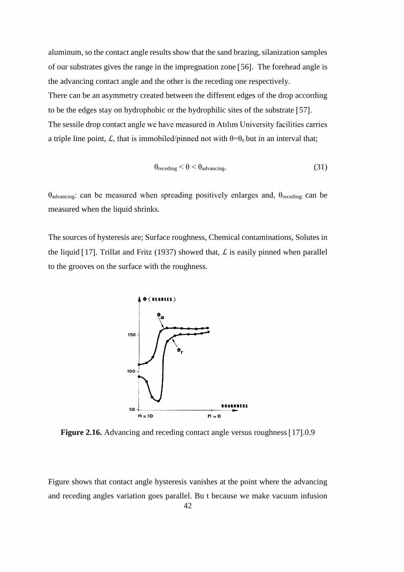
42
aluminum, so the contact angle results show that the sand brazing, silanization samples
of our substrates gives the range in the impregnation zone 56. The forehead angle is
the advancing contact angle and the other is the receding one respectively.
There can be an asymmetry created between the different edges of the drop according
to be the edges stay on hydrophobic or the hydrophilic sites of the substrate 57.
The sessile drop contact angle we have measured in Atılım University facilities carries
a triple line point, ℒ, that is immobiled/pinned not with θ=θe but in an interval that;
θreceding < θ < θadvancing. (31)
θadvancing: can be measured when spreading positively enlarges and, θreceding: can be
measured when the liquid shrinks.
The sources of hysteresis are; Surface roughness, Chemical contaminations, Solutes in
the liquid 17. Trillat and Fritz (1937) showed that, ℒ is easily pinned when parallel
to the grooves on the surface with the roughness.
Figure 2.16. Advancing and receding contact angle versus roughness 17.0.9
Figure shows that contact angle hysteresis vanishes at the point where the advancing
and receding angles variation goes parallel. Bu t because we make vacuum infusion

43
the process itself pushes the liquid drops through the outlet, we can neglect this
phenomenon. So contact angle & roughness figure gives us how the contact angle
changes. When we come to a smoother surface, θr jumps in the second interval from
n=0 to n=10. On the rough side θr and θa are parallel. So we made roughening by sand
papers with parallel motions.
Figure 2.17. Triple line point through grooves 17.0.10
If the grooves are too deep, vapor can be entrapped through the troughs and covered
by the liquid. When the triple line shows an angle to the grooves, there is no pinning
that occurs and ℒ proceeds. Because of sand papers have random arrangement of their
own grids; during resin infusion resins’ way under the negative pressure creates an
angle with the rough surface topography of our aluminum substrate.
The energy change when the liquid changes its position can be predicted as;
dE=r(γsv-γsl)dx+ γlv.dx.cosθ* (32)
cosθ*=r. cosθ, (cosθ*=Cosθrough) (33)
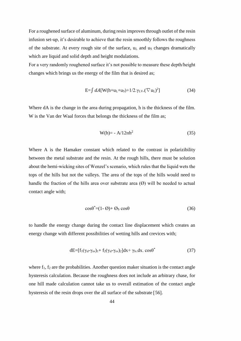
44
For a roughened surface of aluminum, during resin improves through outlet of the resin
infusion set-up, it’s desirable to achieve that the resin smoothly follows the roughness
of the substrate. At every rough site of the surface, uL and uS changes dramatically
which are liquid and solid depth and height modulations.
For a very randomly roughened surface it’s not possible to measure these depth/height
changes which brings us the energy of the film that is desired as;
E=∫𝑑𝐴[W(h+uL+uS)+1/2.γLV.(∇uL)2] (34)
Where dA is the change in the area during propagation, h is the thickness of the film.
W is the Van der Waal forces that belongs the thickness of the film as;
W(h)= - A/12ᴨh2 (35)
Where A is the Hamaker constant which related to the contrast in polarizibility
between the metal substrate and the resin. At the rough hills, there must be solution
about the hemi-wicking sites of Wenzel’s scenario, which rules that the liquid wets the
tops of the hills but not the valleys. The area of the tops of the hills would need to
handle the fraction of the hills area over substrate area (Ø) will be needed to actual
contact angle with;
cosθ*=(1- Ø)+ ØS cosθ (36)
to handle the energy change during the contact line displacement which creates an
energy change with different possibilities of wetting hills and crevices with;
dE=[f1(γsl-γsv)1+ f2(γsl-γsv)2]dx+ γlv.dx. cosθ* (37)
where f1, f2 are the probabilities. Another question maker situation is the contact angle
hysteresis calculation. Because the roughness does not include an arbitrary chase, for
one hill made calculation cannot take us to overall estimation of the contact angle
hysteresis of the resin drops over the all surface of the substrate 56.

45
Equilibrium considerations gives the details of roughness determine the wetting of
roughened substrate surface with a liquid.
Figure 2.18. Capillary pressure identification in a small pour 54.0.11
Penetration to a modeled pore with sizes shown in figure 2, occurs when the pressure
of the air inside the pore balances the capillary pressure 59. This capillary pressure
for a pore is;
Capillary Pressure=2 γ2.sin(θ+Ø)/(r0-x.cot Ø) (38)
If (θ+Ø) <180° then penetration occur.
x=l(1-(Pa.r/2.[2 γ2cosθ+Pa.r]) (39)
means smaller pore gives possibility for penetration 54.

46

47
CHAPTER 3
EXPERIMENTAL PROCEDURE
3.1. Materials
Resin infusion process is one of the composite manufacturing processes used in
different industries, most frequently aviation, naval architecture, railways, component
manufacturing, automotive etc.
Figure 3.1. Typical resin infusion set-up 13.0.1

48
Resin infusion process is a dynamic resin flow process which wets the preform under
the mold with negative pressure sucked from the outlet of the mold. Contamination
caused by the consumables used and void content captured within the mold is critical
in terms of the mechanical behavior of the final product near the optimum wetting.
Although the resin flow can be observed from the top, transverse and in-plane flow of
resin needs to be optimized during labor and set-up planning.
While prepreg-autoclave processed composites reveal the best mechanical
performances because of the low void content-under %2- under the impregnation
spreading is more efficient than other composite manufacturing techniques, it is a long
batch and relatively expensive production method. So the best candidate to replace
prepreg-autoclave process is Resin or Resin Infusion process. Lowering the void
content and improving the wetting of the preform under the mold are going to make
the resin infusion first choice of the industries with its cheap manufacturing
consumables and process. Until now, there is no application that tried out resin
infusion technique for fabricating fiber metal laminated composites.
The consumables used during resin infusion process are as follows;
Resin
Resin Hardener
Sealing Tape
Vacuum Bag
Mold Releasing Paste
Aluminum 2024 T3
Glass Fiber
γ-glycidoxytrimethoxy silane
Sand Paper: 180, 240, 1000
Pure water, ethanol, toluene
Peel ply
Perforated
Vacuum pump

49
Hoses-normal, scratched
Tri-gate junction for resin flow
3.1.1. Resin
During resin infusion process Hexion EpikoteTM MGS LR-160 was used as the
Bisphenol A-epichlorohydrin resin. As resin infusion necessitates very low viscosity
resin, LR-160, which has been widely used in such kind of applications in aerospace
and in the other industries, was selected.
Some tag properties of the resin are given below:
Approval: German Federal Aviation Authority
Boiling Point > 200 °C
Flash Point > 150 °C
Vapor Pressure < 0.14 hpa
Density at 20 °C= 1.13-1.17 g/cm3
Solubility in / Miscibility with water: not miscible or difficult to mix
Viscosity dynamic at 25 °C= 700-900 MPa*s
3.1.2. Resin Hardener
With Hexion EpikoteTM MGS LR-160 resin EpikureTM Curing Agent MGS LH 160 (3-
aminomethyl-3,5,5-trimethylcyclohexylamine) was utilized. Resin and hardener set
used in this study is shown in Figure 3.2.
Boiling point : > 200 °C (392 °F)
Flash point : > 100 °C (212 °F)
Density : ca. 0.960 g/cm3
Solubility in water : insoluble
Viscosity : Dynamic- 10 - 50 mPa·s 25 °C

50
Figure 3.2. Resin and hardener used in this study.0.1
3.1.3. Sealing Tape
While vacuuming the mold, Umeco brand sealant tape enables the air tightness.
Surrounding the mold with the sealant tape and sticking it to the vacuum bag, the mold
will stay under the vacuum properly to handle the negative pressure during the resin
flow. Sealant tape used in this study is shown in Figure 3.3.
Figure 3.3. Sealant tape used in this study.0.1

51
3.1.4. Vacuum Bag
It enables the proper vacuum environment with sealing tape. Different than the
currently applied procedure, there are some applications where two layers of vacuum
bag or vacuum bags for special temperature intervals etc are used. Beside these, to
handle some special surfaces, there are variety of vacuum bags which have porous
surface for different roughness. The vacuum bag used in this study is shown in Figure
3.4.
Figure 3.4. Vacuum used in this study.0.1
3.1.5. Mold Releasing Paste
This product is being smeared gently to the surface of the mold to separate the surface
properly after the curing of the resin. The product shown in Figure 3.5 was used in this
study as its application is easier than that of other mold releasing pastes.

52
Figure 3.5. Releasing paste used in this study.Figure 2
3.1.6. Aluminum 2024 T3 Alloy
Typical characteristics of the aluminum alloy used in this study (Figure 3.6) are as
follows:
Ultimate Tensile Strength: 426 - 431 MPa
Yield Strength: 288 - 292 MPa
Elongation: % 12.5-%16.5
Thickness: 0.5 mm
Figure 3.6. 2024 T3 Aluminum alloy sheets used in this study.0.1

53
3.1.7. Glass Fiber
0/90 degrees oriented, 1/3 cross plied-EC5/112 tex, C class glass fiber woven fabrics
with areal weight 105 g/m2 were used in this study. Typical characteristics of the glass
fiber woven fabrics used (Figure 3.7) are as follows:
Thickness (43%): 0.13 mm
Tensile Elastic Modulus: 19 GPa for both the elastic and the shear modulus
Tensile Strength: 335 MPa
Compressive Strength: 355 MPa
Inter laminar Shear Strength: 45 MPa
Torsional Strength: 495 MPa
Figure 3.7. Glass fiber woven fabrics used in this study.Figure 2
3.1.8. Silane Coupling Agent
In order to prepare the silane solution 95 vol% Ethanol and 5vol% pure water solution
was prepared, and its pH was kept between 4.5-5.5 by acetic acid addition. 0.7 wt% γ-
glycidoxytrimethoxy silane was added to the prepared alcohol-water solution. After
the aluminum surfaces were prepared with proper-contamination free-activated sand
paper and cleaned ultrasonically, the silane solution was sprayed to a single face of the

54
aluminum surfaces. During the silane treatment of the aluminum surfaces a Lotus
AS18-2 vacuum pump with a very small diameter spraying nozzle was utilized (Figure
3.8). After silane solution was sprayed at 0.15 bar pressure, the aluminum sheets were
held at 110 °C for at least 1 h.
Figure 3.8. Spraying of the prepared silane solution to the aluminum surfaces.0.1
3.1.9. Sand Paper
To achieve aluminum surfaces with controlled macro roughness, 180-240 and 1000
sand papers were used (Figure 3.9). In the case of aluminum surfaces containing
grooves and holes, only 1000 grid sand paper was used. On the aluminum samples
without grooves and holes, 180 or 240 grid sand papers were preferred to get more
roughened surface to increase the wetting – adhesion area.
55
Figure 3.9. Sand papers used in this study.0.1
3.1.10. Pure Water, Ethanol, Toluene
While cleaning all of the parts being used during the experiments and sample
preparations, pure water and ethanol have been used. After sand paper abrasion and
ultrasonic cleaning of the aluminum parts, their surfaces have been cleaned with a
toluene soaked lint free towel.
3.1.11. Peel Ply
Peel ply (Figure 3.10) was used to remove the material after the completion of the
curing from the perforated, vacuum bag, breather, flow mesh and surface modifier.

56
Figure 3.10. Peel ply used in this study.0.1
3.1.12. Perforated
During the infusion process, perforated (Figure 3.11) takes the excess resin from the
mold through its holes like a jack-valve operating system without letting the resin to
flow backwards. Perforated was used both after and over the peel ply.
Figure 3.11. Perforated used in this study.0.1

57
3.1.13. Breather and Flow Mesh
Breather is being used to get the excess resin which differs from the perforated by its
cotton like structure which sucks and holds the excess resin. Flow mesh is being used
to make the resin to reach to the end of the mold faster. Decreasing the infusion time
is important because of the limiting resin-end product and product dimensions in some
applications.
3.1.14. Vacuum Pump
During resin infusion process a Telstar 2F9 vacuum pump (Figure 3.12) was used to
create 0.7 bar negative pressure in the mold.
Figure 3.12. Vacuum pump utilized in this study.0.1
3.1.15. Hoses: Normal-Scratched
Normal hoses with different inner-outer radii have been used to suck the air by the
pump on the outlet of the mold side and to suck the resin at the inlet of the mold.
Scratched hoses have been used to separate the resin at the inlet through the width of

58
the mold and to take out the excess resin gathered at the outlet of the mold (Figure
3.13).
Figure 3.13. Hoses: Scratched-Normal used in this study.0.1
3.1.16. Brass Tri-Gate Junctions
To take out the gathered air and resin out of the mold at the outlet and to let the resin
in at the suction side, tri-gate junctions made of brass have been used.
3.2. General Procedure
Fabrication of the fiber metal laminates via resin infusion starts with the surface
modification of the aluminum layers. Before the surface treatments, all of the
aluminum layers were cleansed with ethanol. Applied surface modifications show
variation for different samples. Some horizontally resin infusion applied samples
contain aluminum layers with the grooves and holes introduced. The other samples
have been roughened with sand papers with the proper grids. Aaluminum surface
preparation was finalized by cleaning the layers with ultrasonic cleaner and toluene
degreasing. Contact angle measurement has been conducted on different tailored
surfaces of aluminum substrates.
Resin infusion set-up preparation continued in parallel with the aluminum layer
enhancements. Following the silane treatment of the aluminum surfaces, the bench for

59
composite manufacturing, process set-up, consumables according to sample sizes,
fibers and the other devices/materials were prepared for resin infusion.
After resin infusion, x-ray photos of some parts have been taken to see the hole
arrangement of the fiber metal laminate sample. Following this step, samples were
sliced for three-point bending test according to DIN EN 2563 using Isomet-5000 Micro
Cutter.
After the three-point bending tests, observations of the results according to different
modifications, evaluation of the samples and their surfaces according to fracture and
wetting considerations have been conducted. SEM photos have been taken to see and
to compare the fracture surfaces of different samples of fiber metal laminated
composites fabricated by resin infusion.
In order to make comparison, sand paper and silane treated aluminum samples have
been united with prepreg material those have been produced by Odak
Composites/OSTIM to fabricate the fiber metal laminated composites using hot-
pressing.
3.3. Sample Preparation
3.3.1. Aluminum Layer Preparation
The aluminum used in this study is cladded 2024 T3 alloy which is being used
especially in aerospace industry, therefore procured from TAI - Turkish Air Industries
specially. The characteristics of the 2024 T3 aluminum alloy have been given in the
earlier sections.
Aluminum parts have been sliced to (10 cm X 10 cm) pieces in TAI facilities.
According to DIN EN 2563, three-point bending test specimens must be of size 1 cm
X 10 cm, so 10 cm X 10 cm samples have been fabricated and 3 mechanical testing
specimens were taken out from their central section.

60
To get the maximum wetting during fabricating fiber metal laminated composites with
horizontal resin infusion, aluminum substrate surfaces were modified with holes and
grooves. Holes have been used to wet the inner parts of the mid-range/second and third
layers out of the four aluminum layers of the fiber metal laminated composite. The
arrangement of the holes changed for different samples to see and compare the results
of the inter laminar shear stress resistances of the laminates. In Ergül Makine/OSTIM
facilities, holes have drilled according to the hole arrangement of the sample series.
Drilling has been made with drilling machine by using needle driller at 2400 rpm/min
(Figure 3.14). The radius of the holes is 0.8 mm and was held constant through all of
the parts. To power this intra laminar motion of the resin through the holes and to ease
the triple line point chase on the surfaces of the aluminum laminates grooves have been
used. In the same facilities grooves have been drawn to the surface of the layers using
a manual apparatus which has been adapted for this study.
Figure 3.14. Drilling of holes on 2024 T3 aluminum alloy.0.1

61
Figure 3.15 Hole (a) and groove (b) configurations on aluminum surfaces.0.2
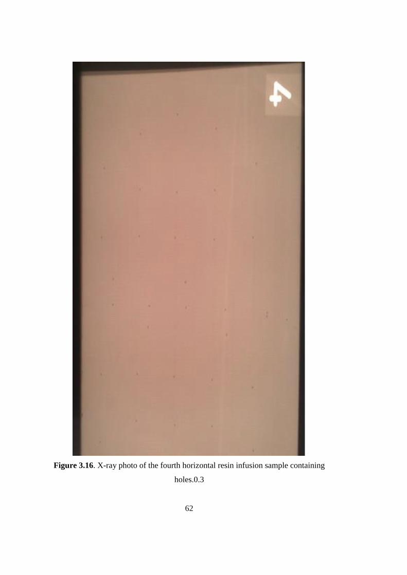
62
Figure 3.16. X-ray photo of the fourth horizontal resin infusion sample containing
holes.0.3

63
After completing the hole – groove modifications of the aluminum layers, abrasion
with 1000 type sand paper was done. The other sand papers like 180/240/500 were
used with the holes and grooves in order to minimize the mechanical deformation.
Through the samples with no holes or grooves, 180 SB, 240 SB and 500 SB papers
have been used before 1000 SB to create macro roughness.
After the completion of the abrasion with sand papers, all of the layers have been
cleansed with acetone and the flatness of the parts have been controlled, and warped
samples were stretched where necessary. After sand paper treatment, all of the
aluminum layers have been cleaned with ultrasonic cleaner for ten minutes applying
50 Hz frequency at 50 C. By using lint free tissue, cleaning and activating the surfaces
with toluene followed ultrasonic cleaning.
Figure 3.17. Ultrasonic cleaning of aluminum substrates after sand paper
abrasion.0.4
Silane preparation began after cleaning operation of the substrates. 95 vol% ethanol
was mixed with 5 vol% pure water for half an hour. After sufficient mixing of these
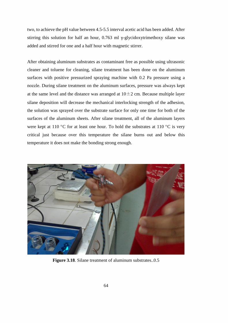
64
two, to achieve the pH value between 4.5-5.5 interval acetic acid has been added. After
stirring this solution for half an hour, 0.763 ml γ-glycidoxytrimethoxy silane was
added and stirred for one and a half hour with magnetic stirrer.
After obtaining aluminum substrates as contaminant free as possible using ultrasonic
cleaner and toluene for cleaning, silane treatment has been done on the aluminum
surfaces with positive pressurized spraying machine with 0.2 Pa pressure using a
nozzle. During silane treatment on the aluminum surfaces, pressure was always kept
at the same level and the distance was arranged at 10±2 cm. Because multiple layer
silane deposition will decrease the mechanical interlocking strength of the adhesion,
the solution was sprayed over the substrate surface for only one time for both of the
surfaces of the aluminum sheets. After silane treatment, all of the aluminum layers
were kept at 110 C for at least one hour. To hold the substrates at 110 C is very
critical just because over this temperature the silane burns out and below this
temperature it does not make the bonding strong enough.
Figure 3.18. Silane treatment of aluminum substrates..0.5

65
After waiting for one hour at 110 C aluminum sheets are ready to make adhesive
bonding to the resin. After heat treatment in the furnace, flatness of the aluminum sheet
has been checked again and stretched gently where needed. Arranging the 4 aluminum
layers with 3 glass fiber layers between them finishes the aluminum preparation.
3.3.2. Resin Infusion Preparation
A thick glass plate containing bench has been produced in Ergül Makine/OSTİM
facilities for only resin infusion experiments and applications in METE/METU
facilities. To minimize the contamination and get the desired clean surface, the surface
of the glass bench has been cleaned with pure water before ethanol and acetone
cleansing. The other steps involved in the preparation for resin infusion are given
below.
The sealing tape has been placed on the bench according to the dimensions of
the fiber metal laminate sample.
The releasing paste has been smeared inside of the sealing tape area. After
pasting the release agent, 10 minutes waiting time was applied.
Vacuum bag and perforated laminate have been prepared according to the
dimensions of the sample.
Scratched hoses with two three gate junctions which fit to the dimensions
were prepared.
After arranging them, aluminum-fiber layers have been placed in the middle
of the prepared site.
Uniting the vacuum bag with the sealant tape and the three gate junctions has
finalized the chamber of the resin infusion.
After tacking the resin and air hoses to the inlet and the outlet of the chamber
respectively, preparations for the resin infusion process were complete. After taking
the air out by vacuuming the chamber, closing the inlet and outlet openings of the
chamber, the system was kept under this condition for nearly 20 minutes to see if there
is any air leakage or not.

66
After seeing that there is no leakage, 40 g resins was mixed with 10 g hardener to
prepare the two component resin. After stirring them slowly enough to avoid the resin
from curing, they have been checked if the initial cloudy view has disappeared or not,
where a clear mixture points out the readiness of the resin for the infusion process.
When the resin has been let to go through the chamber, the chamber has been closed
after seeing the exit of the resin from the outlet, and it was kept under sealed condition
for at least 24 hour for curing.
Figure 3.19. Progress of resin infusion.0.1
After taking the fiber metal laminate sample out of the infusion chamber, it has been
placed in the furnace to post cure. Every sample of the fiber metal laminate composite
has been kept at 80 C for 4 hours or at 63 C for at least 16 hours. After taking the
samples out, their edges were abraded using Metkon Forcipol 2V grinder to get the
proper cutting shape and geometry by removing the residual resin near the sample.
After these steps the samples were ready to make the proper cutting of the three-point

67
bending test specimens. The samples have been sliced with Isomet 5000 micro cutter
with dimensions 1 cm X 10 cm taking them from the mid sections of the samples.
Figure 3.20. Fiber metal laminate composites sliced with micro cutter.0.2
During cutting interval, the blade has released beach marks at the edge of the first
sample. This edge has been created because of the layer differences of the composite
structure, yet at the same time due to the damping of the motion of the blade between
each layer. As a result, a piece of wooden block has been used with the holder of the
micro cutter, and the formation of the beach marks has been suppressed.

68
Figure 3.21. A wooden block has been used to prevent the damping of the blade.0.3

69
Inter laminar Shear Stress Test: The three point bending tests have been done on the
samples which are listed below.
Horizontal resin infusion for hole and 1.5 cm apart groove containing set with
1000 sand paper treatment, where the hole arrangement is given below in the
Figure 3.22. (HV3)
Figure 3.22. Horizontal resin infusion sample containing holes as shown.0.4

70
Horizontal resin infusion for hole and 1.5 cm apart groove containing set with
1000 sand paper treatment, where the hole arrangement is given below in the
Figure 3.23. (HV2)
Figure 3.23. Horizontal resin infusion sample containing holes and 1.5 cm apart
grooves.0.5

71
Horizontal resin infusion for hole and 1.5 cm apart groove containing set with
1000 sand paper treatment, where the hole arrangement is given below in the
figure. (HV1)
Silane treated as received aluminum with prepreg.
180 sand paper treated aluminum with prepreg.
1000 sand paper treated aluminum with prepreg.
Vertical resin infusion sample with 180 sand paper and silane treated
aluminum.
Vertical resin infusion sample with 1000 sand paper and silane treated
aluminum.
Trial sample for different wetting technique of aluminum surface.
The inter laminar shear stress values have been calculated following the three- point
bending tests according to TSE EN 2563 using below given equation.
τ= 3.𝑃4.𝑏.ℎ
(40)
τ=Inter laminar shear stress
P=Actual force
b=width of the sample
h=height of the sample.
Different surface treatments and different composite production methods have been
experienced during the study.
Four types of horizontal resin infusion samples have been prepared. All of them
have roughened with 1000 sand paper and silane treated. HVI-1 has got holes
at every 1cms and at different points between 2nd and 3rd layers with grooves
at every 1 cms. HVI-2 and HVI-3 have circlic pattern of the holes with 35 and
26 holes respectively and grooved at 1.5 cms and 2 cms respectively. HVI-4
sample has holes at every 1.5 cm and at different points between 2nd and 3rd
layers with grooves at every 1.5 cms.

72
Prepreg samples have been silane treated and 180 and 1000 sand papers have
been except as received one.
Vertical resin infusion samples have got no holes nor grooves and silane
treated.
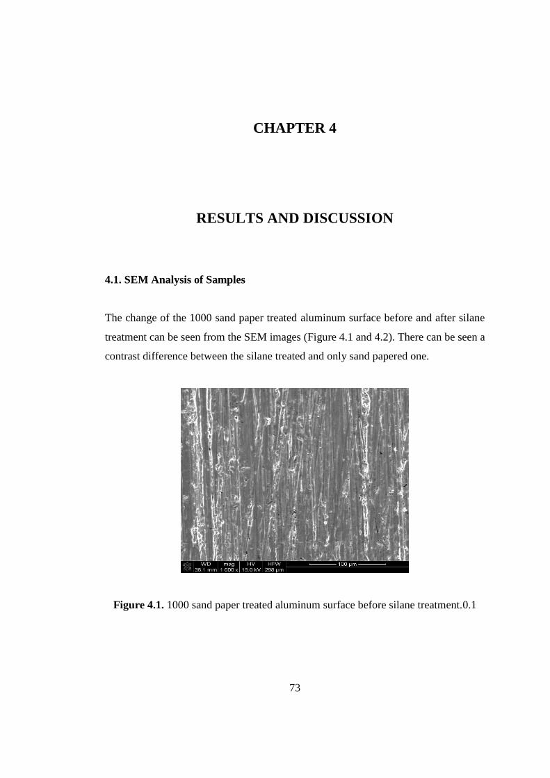
73
CHAPTER 4
RESULTS AND DISCUSSION
4.1. SEM Analysis of Samples
The change of the 1000 sand paper treated aluminum surface before and after silane
treatment can be seen from the SEM images (Figure 4.1 and 4.2). There can be seen a
contrast difference between the silane treated and only sand papered one.
Figure 4.1. 1000 sand paper treated aluminum surface before silane treatment.0.1

74
Figure 4.2. 1000 sand paper treated aluminum surface after silane treatment.0.2
4.2. Contact Angle Measurement
During manufacturing fiber metal composite, wetting is the most important
phenomenon. The contact angle is the main issue to optimize the wetting of resin the
aluminum 2024 T3 substrate. 9 different types of surface topography have been created
on aluminum substrates with as-received aluminum, and contact angle measurements
have been made in Atılım University facilities for these 9 cases. During measurements
SEO 3000 contact angle measurement device has been used.
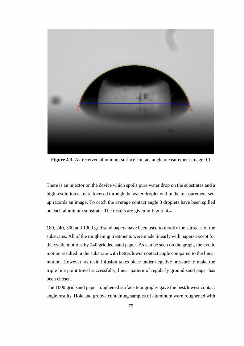
75
Figure 4.3. As-received aluminum surface contact angle measurement image.0.1
There is an injector on the device which spoils pure water drop on the substrates and a
high resolution camera focused through the water droplet within the measurement set-
up records an image. To catch the average contact angle 3 droplets have been spilled
on each aluminum substrate. The results are given in Figure 4.4.
180, 240, 500 and 1000 grid sand papers have been used to modify the surfaces of the
substrates. All of the roughening treatments were made linearly with papers except for
the cyclic motions by 240 gridded sand paper. As can be seen on the graph, the cyclic
motion resulted in the substrate with better/lower contact angle compared to the linear
motion. However, as resin infusion takes place under negative pressure to make the
triple line point travel successfully, linear pattern of regularly ground sand paper has
been chosen.
The 1000 grid sand paper roughened surface topography gave the best/lowest contact
angle results. Hole and groove containing samples of aluminum were roughened with

76
1000 sand paper, where minimum mechanical deformation against other sand papers
and minimum contact angle results were obtained. Silane treated sample of the
aluminum substrate has been roughened with 1000 sand paper because of the same
reason.
Figure 4.4. Aluminum contact angle measurements for different surface
topographies.0.2
The 1000 sand paper did not give the maximum roughness but the best/lowest contact
angles. For some other samples manufactured by prepreg, horizontal or vertical resin
infusion processes different sand papers have been used.

77
4.3. Roughness Measurement
Roughening the surface increases the adhesion area. Because of this fact, aluminum
substrate surfaces have been roughened using sand papers. Different average
roughness values were created by sand papers having grid sized as shown in Figure
4.5. Although it has the optimum contact angle, 1000 sand papered surface (1000 SB)
has got the lowest average roughness values among the others. However, after silane
treatment (1000 SB+Si) the roughness increases to a value that is advantageous
compared to only degreased aluminum surface topography.
Figure 4.5. Average surface roughness values of different sand paper treatments.
Figure 3
The values were measured in Micro Electro Mechanic Science/METU
laboratories/facilities. Using the optical profilometer by Veeco all of the surfaces
treated by varying methods were examined, and the light emitting performances of
each of them gave the reflecting topography of the substrates. An example of the

78
measurements, for the 1000 sand paper and silane treated surface (1000 SB+Si ) can
be seen with a groove in the Figure 4.6 (a).
The optical profilometer provides average roughness values, as shown by red arrow in
figure 4.7, yet also measures the maximum depth and height data of the surface
topography simultaneously. At the same time from overall view of the other optical
profilometer, the existing linearity of the sand paper treated surface lines can be
observed by the special images which are called surface data as shown in the Figure
4.6 (b).
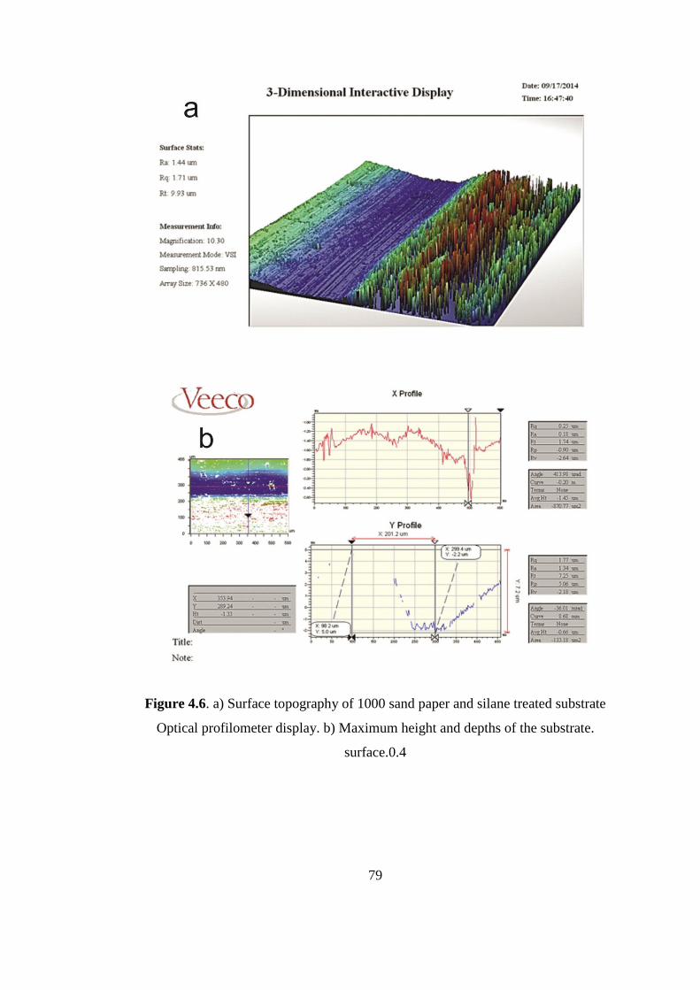
79
Figure 4.6. a) Surface topography of 1000 sand paper and silane treated substrate
Optical profilometer display. b) Maximum height and depths of the substrate.
surface.0.4
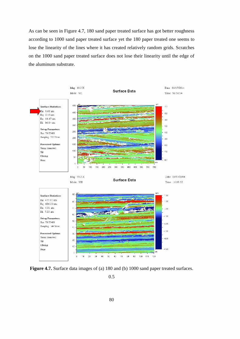
80
As can be seen in Figure 4.7, 180 sand paper treated surface has got better roughness
according to 1000 sand paper treated surface yet the 180 paper treated one seems to
lose the linearity of the lines where it has created relatively random grids. Scratches
on the 1000 sand paper treated surface does not lose their linearity until the edge of
the aluminum substrate.
Figure 4.7. Surface data images of (a) 180 and (b) 1000 sand paper treated surfaces.
0.5

81
If it is assumed that the maximum value of height of roughness 2.9 m has been
achieved on the 180 sand paper treated surface, the capillary pressure needed to
overcome the trapped air in the so called regular little hills by the same roughness can
be determined, as discussed in Chapter 2 in the wetting analysis. However, in the
present case the negative pressure achieved in the mold during resin infusion is large
enough to overcome that capillary pressure. So this is not a threat for resin infusion
process unlike prepreg/autoclave considerations.
Figure 4.8. Surface tension measurement of the resin. Figure 6

82
Capillary rise of the resin in the hose is shown in figure 4.8. As can be seen in the
reference [17];
2𝛾
𝑅= 𝜌. 𝑔. ℎ (41)
γ=surface energy of the liquid
ρ=density of the liquid=1,13 gr/cm3
h=height of the liquid in the hose=9,7 cm
R=radius of the capillary rise
𝑅 =𝑅1
𝑐𝑜𝑠𝜃 (42)
θ=Angle of the capillary rise=32,54°
R1=inner radius of the hose=3,5 mm
R=8,1 mm
γ=8,71 N/m
Young’s contact angle can be calculated by using equation (20) so;
γcosθ= γSV- γSL (43)
Using this analysis γSV- γSL for different modified surfaces gives spreading coefficient,
S;
S=γSV- γSL- γ (44)
S= γcosθ – γ (45)
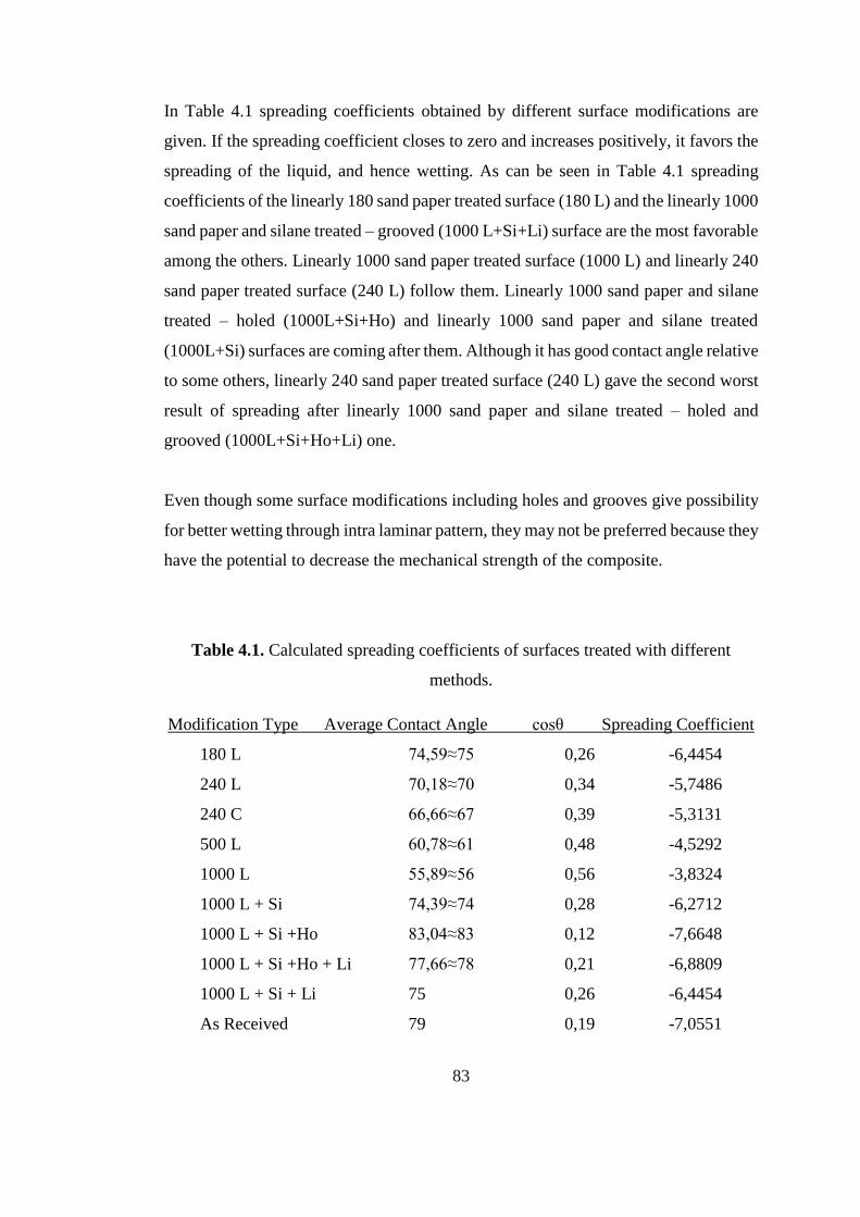
83
In Table 4.1 spreading coefficients obtained by different surface modifications are
given. If the spreading coefficient closes to zero and increases positively, it favors the
spreading of the liquid, and hence wetting. As can be seen in Table 4.1 spreading
coefficients of the linearly 180 sand paper treated surface (180 L) and the linearly 1000
sand paper and silane treated – grooved (1000 L+Si+Li) surface are the most favorable
among the others. Linearly 1000 sand paper treated surface (1000 L) and linearly 240
sand paper treated surface (240 L) follow them. Linearly 1000 sand paper and silane
treated – holed (1000L+Si+Ho) and linearly 1000 sand paper and silane treated
(1000L+Si) surfaces are coming after them. Although it has good contact angle relative
to some others, linearly 240 sand paper treated surface (240 L) gave the second worst
result of spreading after linearly 1000 sand paper and silane treated – holed and
grooved (1000L+Si+Ho+Li) one.
Even though some surface modifications including holes and grooves give possibility
for better wetting through intra laminar pattern, they may not be preferred because they
have the potential to decrease the mechanical strength of the composite.
Table 4.1. Calculated spreading coefficients of surfaces treated with different
methods.
Modification Type Average Contact Angle cosθ Spreading Coefficient
180 L 74,59≈75 0,26 -6,4454
240 L 70,18≈70 0,34 -5,7486
240 C 66,66≈67 0,39 -5,3131
500 L 60,78≈61 0,48 -4,5292
1000 L 55,89≈56 0,56 -3,8324
1000 L + Si 74,39≈74 0,28 -6,2712
1000 L + Si +Ho 83,04≈83 0,12 -7,6648
1000 L + Si +Ho + Li 77,66≈78 0,21 -6,8809
1000 L + Si + Li 75 0,26 -6,4454
As Received 79 0,19 -7,0551

84
According to Young’s equation, roughness factor-r=A/Ao can be found using as given
in DeGennes’ beautiful review[17];
cosθrough=r.cosθsmooth (46)
where θrough and θsmooth are contact angles of the roughened and smooth surfaces
respectively, and r is the roughness factor, in order to give idea about the increased
area amount of the roughened surfaces.

85
Figure 4.9. From a)Vertical and b)Horizontal views of fabricated samples .Figure 0.7
Table 4.2 Roughness Factor.
Modification Type Contact Angle Rough cosθsmooth Roughness Factor
180 L 74,59≈75 0,26 1,3684
240 L 70,18≈70 0,34 1,7894
240 C 66,66≈67 0,39 2,0526
500 L 60,78≈61 0,48 2,5263
1000 L 55,89≈56 0,56 2,9473
1000 L + Si 74,39≈74 0,28 1,4736
1000 L + Si +Ho 83,04≈83 0,12 0,6315
1000 L + Si +Ho + Li 77,66≈78 0,21 1,1052
1000 L + Si + Li 75 0,26 1,3684
As Received 79 0,19 1

86
Inter laminar shear stress values calculated by the data obtained using the three-point
bending tests are given in Figure 4.8.
Figure 4.10. Inter laminar shear stress values of the fiber metal laminated composite
samples.0.8
4 of the horizontal resin infusion samples representatively shown in Figure 4.10
contain fracture between the resin and the glass fiber. This shows that silane treatments
has a positive effect yet because of the low inter laminar shear stress value the silane
could not carry the adhesive load of the fiber metal laminated composite. The other
four samples could not even be tested, because they have delaminated during cutting
operation. Silane treated as received aluminum substrates which have been used during
horizontally resin infusion sample preparation and with prepreg could not have been
shown, either, because they have also delaminated during cutting operation.

87
Horizontal resin infusion samples revealed different results. Some samples fractured
from the fiber-resin composite and some of the samples showed mixed fracture type.
There is no consistency that could have created between them.
The HV-3 gave the highest inter laminar shear stress results and the best response to
the splicing method optimization. It can be seen from Figure 4.11 that the line between
the fiber-resin and the aluminum substrate is very thin and shows linearity through the
line regularly. The splicing method application to this sample showed resistance
against buckling or crack initiation in the interfaces with the optimum wetting (Figure
4.11). Figure.4.11 compares the separation intervals of the ref.[10] and ours.
Prepreg samples gave the lowest results as shown in the Figure 4.12. All of the sand
paper-silane treated prepreg samples gave low inter laminar shear stress values which
can be explained, as seen in Figure 4.12, by the huge space between the aluminum
substrate and the prepreg. Therefore, it can be said that prepreg material does not give
good results with silane treatment over the aluminum substrates.
In the aviation industry, GLARE® laminates have been fabricated with prepreg-
autoclave manufacturing system. In this case, an adhesive primer, like BR 127, has
been applied on the aluminum surfaces to increase the bonding strength with the
prepreg. Prepregs have been used with other surface treatments in the literature like
primer adhesive and anodizing which chase chemical etching. But in our case, the
prepreg didn’t make desired bonding because the resin completed its’ reaction and
couldn’t make the bond with silane.
These reasons make prepreg-autoclave manufacturing system unavailable for other
surface treatments without primers. It has been mentioned that the prepreg-autoclave
manufacturing system has got disadvantages being a long-batch process, using high
electrical energy with high pressure and temperature within the autoclave and being
rigid against complex shaping. Furthermore, the primer application increases the costs
and the labor during fiber-metal laminated composite fabrication.

88
Vertical resin infusion samples showed relatively good values in terms of flexural and
inter laminar shear stress. Although the values of the force during three-point bending
stress test of vertical resin infusion samples, show consistency and give good results,
the values are lower then the best horizontal resin infusion values. They showed very
thin line of seperation between the fiber-resin composite and the aluminum substrate.
However, one out of six samples showed delamination. Vertical resin infusion samples
have the best average inter laminar shear stress values among the others fabricated by
different systems.
When the stress-strain behavior given in Figure 4.14 and 4.15 are compared, it can be
said that most of the fiber metal laminates fabricated in the scope of this study show
stress-strain response close to those of Airbus Standart-GLARE® both in terms of
strength and elongation.
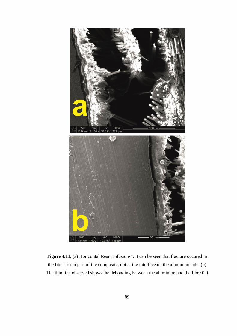
89
Figure 4.11. (a) Horizontal Resin Infusion-4. It can be seen that fracture occured in
the fiber- resin part of the composite, not at the interface on the aluminum side. (b)
The thin line observed shows the debonding between the aluminum and the fiber.0.9

90
Figure 4.12. Horizontal resin infusion-HV-1 sample showing mixed type fracture,
first from the fiber-resin composite than from the aluminum surface..0.10
Figure 4.13. a) Horizontal resin infusion sample-HVI-7, showed cohesiveness of
inter laminar shear stress against three-point bending test and did not show
delamination. b) Debonding between aluminum and fibers in 220 sand blasting and
phosphoric acid anodizing processed GLARE® 10. 0.11

91
Figure 4.14. 1000 Sand Paper and Silane treated prepreg sample.0.12
Figure 4.15. Vertical resin infusion sample-180 sand paper and silane treated.0.13
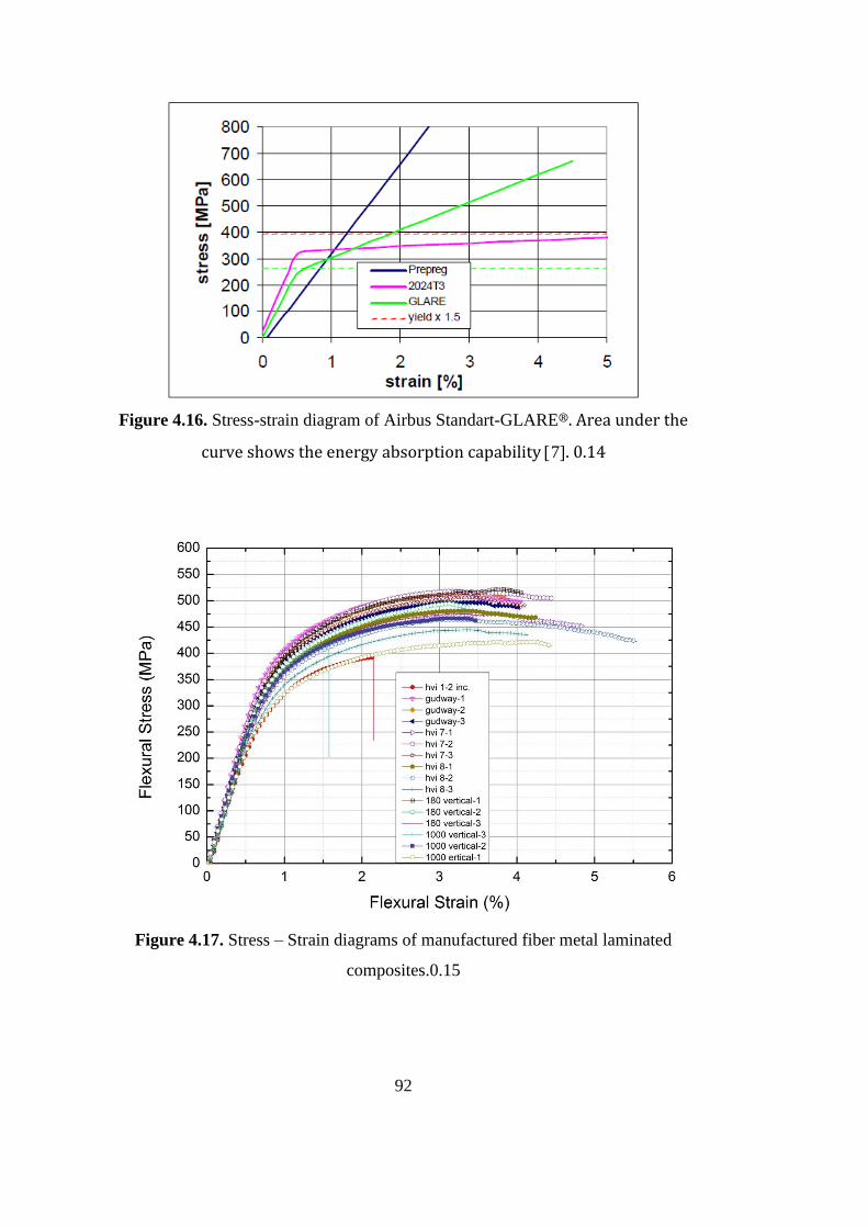
92
Figure 4.16. Stress-strain diagram of Airbus Standart-GLARE®. Area under the
curve shows the energy absorption capability 7. 0.14
Figure 4.17. Stress – Strain diagrams of manufactured fiber metal laminated
composites.0.15

93
When we compare the inter laminar shear stress results with the literature it can be
seen that the inter laminar shear stress results extracted in this study are higher than
the results as seen in the figure 4.18 from the ref.[60] , The strain rate in this study is
1 mm/minute.
Figure.4.18. Variation of inter laminar shear strength as a function of strain rates for
different fiber metal laminated structures.ref.[60]
The flexural stress results show and can be compared with aircraft company products
and this manufacturing and surface treatment techniques can be used to fabricate fiber
metal laminates for impact resistant and fatigue prone areas of the vessels. As assumed
before the three point bending tests, it can be understood that the crack initiation and
propagation started and created failure not between the metal substrates and the fiber-
resin composites but between the fiber and the resin when the delamination or
debonding have not been observed at the end of the tests.

94

95
CHAPTER 5
CONCLUSIONS
Resin infusion and tuned resin infusion processes will be the choice for the next
generation fiber metal laminated composite manufacturing for different industries. As
presented in this study, different types or modified kinds of silane may be used in the
future to enhance the bonding of different fibers in laminated composites. The most
important issue for the resin infusion process is create the know-how towards the
appropriate use of the consumables involved.
Contamination is one of the main issues so manufacturing can be done in clean room
facilities. Void content is the other main issue to be kept under control applying
sensitive laboring.
From this study it is experienced that;
Vertical resin infusion showed better consistency and can be tailored for fiber
metal laminate manufacturing in the future by resin infusion technique.
Fiber metal laminates can be manufactured by resin infusion method and
horizontal resin infusion must be tailored and simulated for the efficiency and
mechanical strength of the fiber metal laminates with the cyclic pattern of the
holes and minimum grooves which give the best results according to splicing
method.
Silane treatment is an efficient method for surface adhesion.

96
Sand paper treatment increases roughness and does not decrease mechanical
strength of the aluminum so the treatments that have hazards can be
eliminated by this simple method.

97

98
REFERENCES
1. Asundi, A., & Choi, A. Y. N. (1997). Materials Processing Technology Fiber
Metal Laminates : An Advanced Material for Future Aircraft.
2. Cocchieri, E., Almeida, R., José, S., & Paulo, S. (2006). A Review on the
Development and Properties of Continuous Fiber / epoxy / aluminum Hybrid
Composites for Aircraft Structures 2 . The Production of Metal / laminate
Hybrid Composites, 9(3), 247–256.
3. Wu, G., & Yang, J.-M. (2005). Analytical modelling and numerical simulation
of the nonlinear deformation of hybrid fibre–metal laminates. Modelling and
Simulation in Materials Science and Engineering, 13(3), 413–425.
doi:10.1088/0965-0393/13/3/010
4. Cepeda-Jiménez, C. M., Alderliesten, R. C., Ruano, O. a., & Carreño, F.
(2009). Damage tolerance assessment by bend and shear tests of two multilayer
composites: Glass fibre reinforced metal laminate and aluminium roll-bonded
laminate. Composites Science and Technology, 69(3-4), 343–348.
doi:10.1016/j.compscitech.2008.10.010
5. Beumler, T.,(2004) A contribution to aircraft certification issues on strength
properties in non-damaged and fatigue damaged GLARE® structures,Flying
GLARE®.Retrieved November 2014 from
file:///C:/Users/notebook/Desktop/ae_beumler_20040323.pdf.
6. Vermeeren, C. A. J. R., Kanter, J. L. C. G. D. E., Jagt, O. C. V. A. N. D. E. R.,
& Out, B. C. L. (2003). Glare® Design Aspects and Philosophies, 257–276.
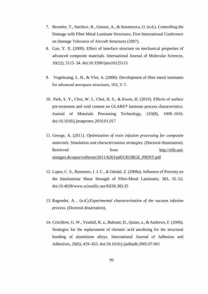
99
7. Beumler, T., Starikov, R., Gennai, A., & Senatorova, O. (n.d.). Controlling the
Damage with Fiber Metal Laminate Structures, First International Conference
on Damage Tolerance of Aircraft Structures (2007).
8. Gan, Y. X. (2009). Effect of interface structure on mechanical properties of
advanced composite materials. International Journal of Molecular Sciences,
10(12), 5115–34. doi:10.3390/ijms10125115
9. Vogelesang, L. B., & Vlot, A. (2000). Development of fibre metal laminates
for advanced aerospace structures, 103, 3–7.
10. Park, S. Y., Choi, W. J., Choi, H. S., & Kwon, H. (2010). Effects of surface
pre-treatment and void content on GLARE® laminate process characteristics.
Journal of Materials Processing Technology, 210(8), 1008–1016.
doi:10.1016/j.jmatprotec.2010.01.017
11. George, A. (2011). Optimization of resin infusion processing for composite
materials: Simulation and characterization strategies. (Doctoral dissertation).
Retrieved from http://elib.uni-
stuttgart.de/opus/volltexte/2011/6263/pdf/GEORGE_PRINT.pdf
12. Lopes, C. S., Remmers, J. J. C., & Gürdal, Z. (2008a). Influence of Porosity on
the Interlaminar Shear Strength of Fibre-Metal Laminates, 383, 35–52.
doi:10.4028/www.scientific.net/KEM.383.35
13. Ragondet, A. . (n.d.).Experimental characterization of the vacuum infusion
process. (Doctoral dissertation).
14. Critchlow, G. W., Yendall, K. a., Bahrani, D., Quinn, a., & Andrews, F. (2006).
Strategies for the replacement of chromic acid anodising for the structural
bonding of aluminium alloys. International Journal of Adhesion and
Adhesives, 26(6), 419–453. doi:10.1016/j.ijadhadh.2005.07.001

100
15. Park, S. Y., Choi, W. J., Soap, H., Kwon, H., Kim, S. H., & City, K. (2010).
Recent Trends in Surface Treatment Technologies for Airframe Adhesive
Bonding Processing : A Review, (July 2012), 192–221.
16. Chamis, C. C., National aeronautics and space administration cleveland oh
lewis research center, (1972). Mechanics of load transfer at the fiber/matrix
interface. Retrieved from National Aeronautics and Space Administration
Cleveland OH Lewis Research Center
17. deGennes, P.G., (1985).,Wetting: statics and dynamics, Review of modern
physics57,827
18. June, J. W. M. B. (2013). 18.357 Interfacial Phenomena, Fall 2010
19. Duncan, B., Mera, R., Leatherdale, .D., Taylor, M., Musgroove, R.,(2005).
Techniques for characterizing the wetting, coating and spreading of adhesives
on surfaces, National Physics Laboratory
20. Bonn, D., Eggers, J., Indekeu, J., Meunier, J., & Rolley, E. (2009). Wetting and
spreading. Reviews of Modern Physics, 81(2), 739–805.
doi:10.1103/RevModPhys.81.739
21. .Branco, C. M., Ferreira, J. M., Faelt, P., & Richardson, M. O. W. (1996). A
comparative study of the fatigue behaviour of GRP hand lay-up and pultruded
phenolic composites, 18(4), 255–263.
22. Belingardi, G., Cavatorta, M. P., & Salvatore Paolino, D. (2008). Repeated
impact response of hand lay-up and vacuum infusion thick glass reinforced
laminates. International Journal of Impact Engineering, 35(7), 609–619.
doi:10.1016/j.ijimpeng.2007.02.005
23. Gangloff, J. J., Simacek, P., Sinha, S., & Advani, S. G. (2014). A process
model for the compaction and saturation of partially impregnated thermoset

101
prepreg tapes. Composites Part A: Applied Science and Manufacturing, 64,
234–244. doi:10.1016/j.compositesa.2014.05.010
24. Grunenfelder, L. K., & Nutt, S. R. (2010). Void formation in composite
prepregs – Effect of dissolved moisture. Composites Science and Technology,
70(16), 2304–2309. doi:10.1016/j.compscitech.2010.09.009
25. Baumert, E. K., Johnson, W. S., Cano, R. J., Jensen, B. J., & Weiser, E. S.
(n.d.). MECHANICAL EVALUATION OF NEW FIBER METAL
LAMINATES MADE BY THE VARTM PROCESS.
26. Sala, G., & Camille, V. (1996). Advances in elastomeric tooling technology,
17(1), 33–42.
27. Morozov, E. V. (2006). The effect of filament-winding mosaic patterns on the
strength of thin-walled composite shells. Composite Structures, 76(1-2), 123–
129. doi:10.1016/j.compstruct.2006.06.018
28. Vargas Rojas, E., Chapelle, D., Perreux, D., Delobelle, B., & Thiebaud, F.
(2014). Unified approach of filament winding applied to complex shape
mandrels. Composite Structures, 116, 805–813.
doi:10.1016/j.compstruct.2014.06.009
29. Wu, H. F., Wu,L.L., Slagter, J.W.,Verolme, L.J.,(1994). Use of rule of
mixtures and metal volume fraction for mechanical property predictions of
fibre-reinforced aluminium laminates Journal of Materials Science,29, 4583
.
30. Wu, G., & Yang, J. (2005). The Mechanical Behavior of GLARE® Laminates
for Aircraft Structures,57, 72-79.

102
31. Kaufman,J.G. (1967). Fracture toughness of 7075-T6 and T651 sheet, plate
and multilayered adhesive-bonded panles, journal of basic engineering,
89,503-507
32. Johnson, W.S., Rister, W.C., and Spamer, T. (1978). Spectrum crack growth
in adhesively bonded structure ASME Journal of Engineering Materials and
Technology, 100,57-63
33. Johnson, W.S. (1983).Damage tolerance evaluation of adhesively laminated
titanium, ASME Journal of Material science and technology, vol.105,182-187.
34. Krishnakumar, S. (1994). Fiber Metal Laminates-the synthesis of metals and
composite, Materials and manufacturing process, 9, 295-354.
35. Young, J.B., Landry, J.G.N., and Cavoulacos, V.N. (1994). Crack growth and
residual strength characteristics of two grades of glass-reinforced aluminum
’GLARE ®, Composite Structures, 27,457-469.
36. Pitzer, C., Yang, J. M.,(2008).Hybrid Metal Laminate Manufacturing Planning
Evaluation and assessment Retrieved November .2014 from
http://www.pitzerconsulting.com/docs/FML-
assessment_yang_pitzer_2009.pdf
37. Critchlow, G. W., & Brewis, D. M. (1996). Review of surface pretreatments
for aluminum alloys, 16(4), 255–275.
38. Higgins, A. (2000). Adhesive bonding of aircraft structures , 20(January), 367–
376
39. Oosting, R. (1995).Toward a new durable and environmentally compliant
adhesive bonding process for aluminum alloys. (Doctoral dissertation).,

103
40. Davis, G. D. and Venables, J. D. (2002). Surface Treatments of Metal
Adherends,(Elsevier, Amsterdam,), 1st ed., Vol. 2, Ch. 21, pp. 947–1008.
41. Matz, C. W., Hilling, B., Kelm, W., and Kock, E. (September, 1996)
Phosphoric Sulfuric Acid Anodizing (PSA) – A Heavy Metal Free Alternative
for High Quality Surface Pretreatment of Aluminum, in: 83rd Meeting of the
AGARD Structures and Materials Panel, Florence, Italy.
42. Johnsen, B.B. (2003). Adhesive bonding of aluminum (Doctoral dissertation)
43. Rider, A. N., & Arnott, D. R. (2000). Boiling water and silane pre-treatment of
aluminium alloys for durable adhesive bonding, 20
44. Abel, M.L., Watts, J.F.and Digby, R.P. (1998), The adsorption of alkoxysilanes
on oxidised aluminium substrates,Int.J.Adhes.Adhes., 18, 179-192
45. . I, R. P., & Paekham, D. E. (1995). Pretreatment of aluminium : topography ,
surface chemistry and adhesive bond durability, 15(2), 61–7
46. Mahesh, M., & A, S. K. (n.d.). Comparison Of Mechanical Properties For
Aluminium Metal Laminates ( GLARE® ) Of Three Different Orientations
Such As CSM , Woven Roving And 45 0 Stitched Mat, 9–13.
47. Hagenbeek, M., Hengel, C. V. A. N., Bosker, O. J., & Vermeeren, C. A. J. R.
(2003). Static Properties of Fibre Metal Laminates, 207–222.
48. Chamis, C. C. (n.d.). MECHANICS OF LOAD TRANSFER AT THE FIBER
/ MATRIX INTERFACE.
49. Kashtalyan, M., & Soutis, C. (2007). Stiffness and fracture analysis of
laminated composites with off-axis ply matrix cracking. Composites Part A:
104
Applied Science and Manufacturing, 38(4), 1262–1269.
doi:10.1016/j.compositesa.2006.07.001
50. Airoldi, A., Vesco, M., Zwaag, S. Van Der, Baldi, A., Sala, G., & Masa, V. La.
(n.d.). DAMAGE IN GLARE® LAMINATES UNDER INDENTATION
LOADS : EXPERIMENTAL AND NUMERICAL RESULTS.
51. Nam, H. W. (2012). Design Factor Analysis of Fiber Metal Laminates under
Concentrated Load by Using Design of Experiment. Applied Mechanics and
Materials, 248, 167–172. doi:10.4028/www.scientific.net/AMM.248.167
52. Wang, W. D., Alderliesten, R. C., & Benedictus, R. (2014). On the
Development of a Prediction Methodology for Crack Growth in Fibre Metal
Laminates with MSD Scenario. Advanced Materials Research, 891-892, 1651–
1656. doi:10.4028/www.scientific.net/AMR.891-892.1651
53. Fowkes, F.M.(1962), Determination of Interfacial Tensions, Contact Angles
and Dispersion Forces in Surfaces by Assuming Additivty of Intermolecular
Interactions in Surfaces,J.Phys.Chem.66,382
54. Packham, D. . (2003). Surface energy, surface topography and adhesion.
International Journal of Adhesion and Adhesives, 23(6), 437–448.
doi:10.1016/S0143-7496(03)00068-X
55. Shafrin, E.G., Zisman,W.A.(1964) Contact angle, wettability and adhesion,
Advances in Chemistry Series, 43, 145–157.
56. .Quere, D.(2002) Rough ideas on wetting, Physica A, 313,32-42
57. Bico, J.,Thiele, U., & Quere, D. (2002). Wetting of textured surfaces, 206, 41–
46.

105
58. Elizabeth, B.,Dussan ,V., B., Davis, S.H., (1974). On the motion of a fluid-
fluid interface along a solid surface, Journal of Fluid Mechanics,65,71-95.
59. , E., Prost, J., & Bouletl, C. (1982). Attention aux tensions superficielles , 159
60. Investigation of tensile and bending behavior of aluminum based hybrid fiber
metal laminates by, G.R. Rajkumar, M.Krishna, H.N.Narasimhamurthy,
KEshavamurthy, Y.C., J.R.Nataraj.