fe-107 experimental validation - paulin · fe-107 experimental validation ... during the analysis,...
TRANSCRIPT
Experimental Validation shows that FE-
107 Provides More Accurate Results
than WRC-107
Copyright© 2008 - Paulin Research Group
FE-107 Experimental Validation
Has your finite element analysis (FEA) software been validated against real-world pressure
vessel problems? FE-107 and other PRG software are continuously validated against actual
problems faced by practicing engineers. Follow this link for to learn more about an
experimental validation of the FE-107 solutions and see how WRC 107 fails to predict
accurate stresses in a real world application.
Real-world validation of PVP Designs
Validation comes in two forms: numerical validations and real-world validations. All FEA
programs are numerically validated…few are validated against problems you face everyday
in the pressure vessel and piping industry.
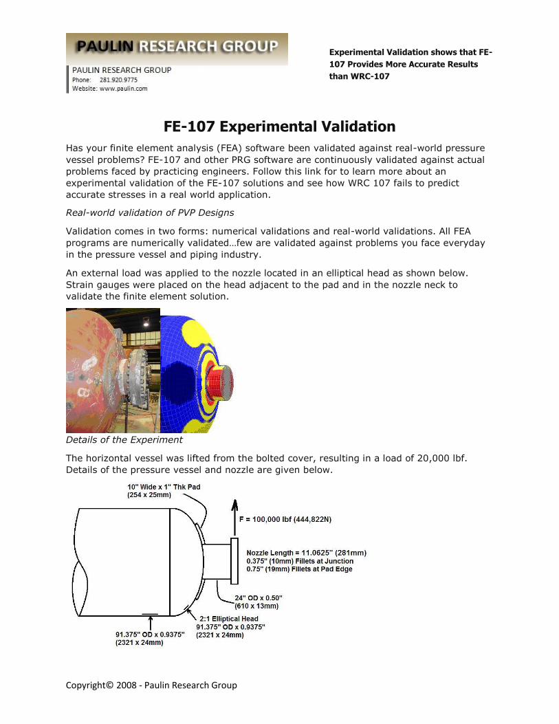
An external load was applied to the nozzle located in an elliptical head as shown below.
Strain gauges were placed on the head adjacent to the pad and in the nozzle neck to
validate the finite element solution.
Details of the Experiment
The horizontal vessel was lifted from the bolted cover, resulting in a load of 20,000 lbf.
Details of the pressure vessel and nozzle are given below.
Experimental Validation shows that FE-
107 Provides More Accurate Results
than WRC-107
Copyright© 2008 - Paulin Research Group
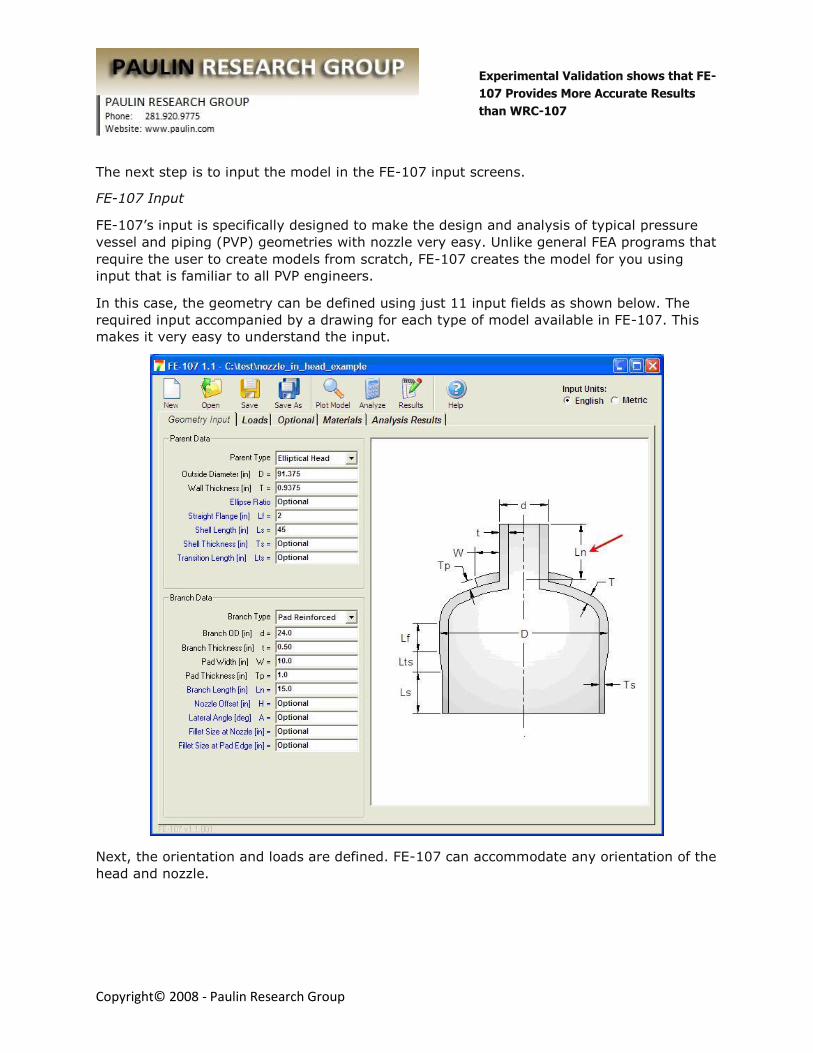
The next step is to input the model in the FE-107 input screens.
FE-107 Input
FE-107’s input is specifically designed to make the design and analysis of typical pressure
vessel and piping (PVP) geometries with nozzle very easy. Unlike general FEA programs that
require the user to create models from scratch, FE-107 creates the model for you using
input that is familiar to all PVP engineers.
In this case, the geometry can be defined using just 11 input fields as shown below. The
required input accompanied by a drawing for each type of model available in FE-107. This
makes it very easy to understand the input.
Next, the orientation and loads are defined. FE-107 can accommodate any orientation of the
head and nozzle.
Experimental Validation shows that FE-
107 Provides More Accurate Results
than WRC-107
Copyright© 2008 - Paulin Research Group
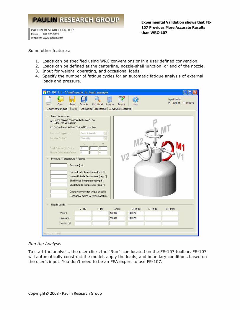
Some other features:
1. Loads can be specified using WRC conventions or in a user defined convention.
2. Loads can be defined at the centerline, nozzle-shell junction, or end of the nozzle.
3. Input for weight, operating, and occasional loads.
4. Specify the number of fatigue cycles for an automatic fatigue analysis of external
loads and pressure.
Run the Analysis
To start the analysis, the user clicks the “Run” icon located on the FE-107 toolbar. FE-107
will automatically construct the model, apply the loads, and boundary conditions based on
the user’s input. You don’t need to be an FEA expert to use FE-107.
Experimental Validation shows that FE-
107 Provides More Accurate Results
than WRC-107
Copyright© 2008 - Paulin Research Group
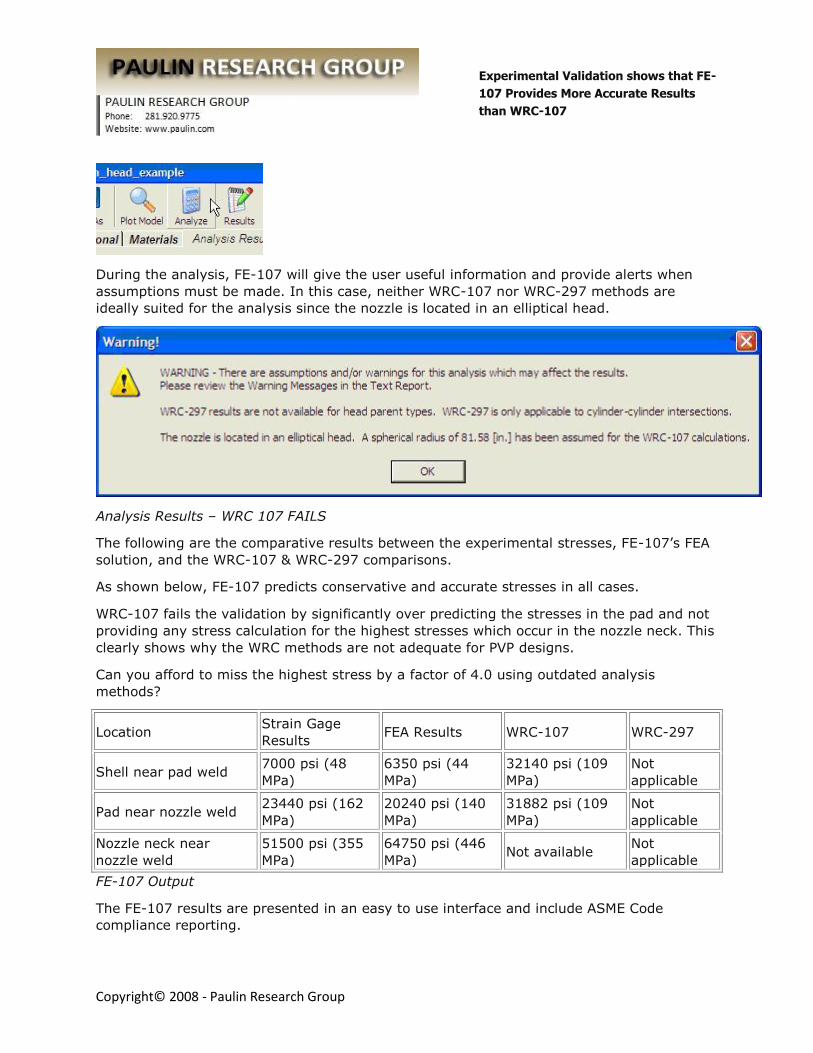
During the analysis, FE-107 will give the user useful information and provide alerts when
assumptions must be made. In this case, neither WRC-107 nor WRC-297 methods are
ideally suited for the analysis since the nozzle is located in an elliptical head.
Analysis Results – WRC 107 FAILS
The following are the comparative results between the experimental stresses, FE-107’s FEA
solution, and the WRC-107 & WRC-297 comparisons.
As shown below, FE-107 predicts conservative and accurate stresses in all cases.
WRC-107 fails the validation by significantly over predicting the stresses in the pad and not
providing any stress calculation for the highest stresses which occur in the nozzle neck. This
clearly shows why the WRC methods are not adequate for PVP designs.
Can you afford to miss the highest stress by a factor of 4.0 using outdated analysis
methods?
Location Strain Gage
Results FEA Results WRC-107 WRC-297
Shell near pad weld 7000 psi (48
MPa)
6350 psi (44
MPa)
32140 psi (109
MPa)
Not
applicable
Pad near nozzle weld 23440 psi (162
MPa)
20240 psi (140
MPa)
31882 psi (109
MPa)
Not
applicable
Nozzle neck near
nozzle weld
51500 psi (355
MPa)
64750 psi (446
MPa) Not available
Not
applicable
FE-107 Output
The FE-107 results are presented in an easy to use interface and include ASME Code
compliance reporting.
Experimental Validation shows that FE-
107 Provides More Accurate Results
than WRC-107
Copyright© 2008 - Paulin Research Group
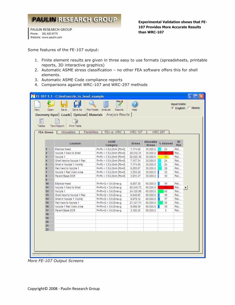
Some features of the FE-107 output:
1. Finite element results are given in three easy to use formats (spreadsheets, printable
reports, 3D interactive graphics)
2. Automatic ASME stress classification – no other FEA software offers this for shell
elements.
3. Automatic ASME Code compliance reports
4. Comparisons against WRC-107 and WRC-297 methods
More FE-107 Output Screens

Experimental Validation shows that FE-
107 Provides More Accurate Results
than WRC-107
Copyright© 2008 - Paulin Research Group
Interactive 3-D graphical results for evaluating results.
Experimental Validation shows that FE-
107 Provides More Accurate Results
than WRC-107
Copyright© 2008 - Paulin Research Group
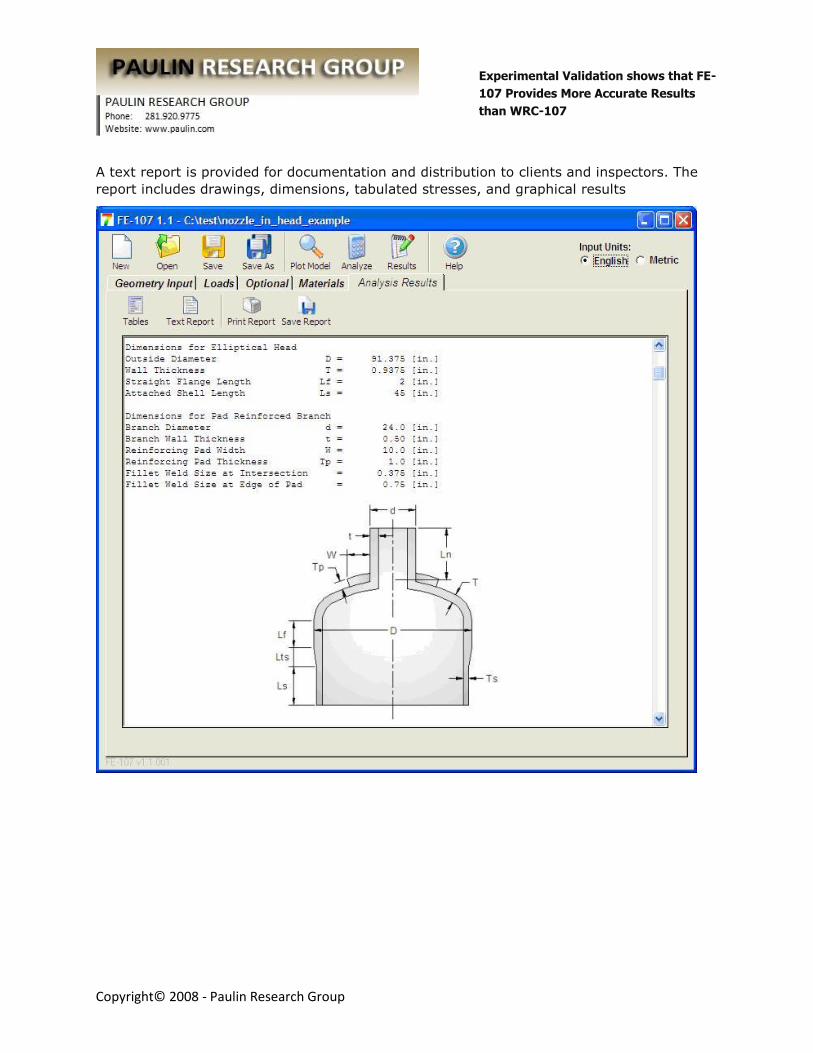
A text report is provided for documentation and distribution to clients and inspectors. The
report includes drawings, dimensions, tabulated stresses, and graphical results
Experimental Validation shows that FE-
107 Provides More Accurate Results
than WRC-107
Copyright© 2008 - Paulin Research Group
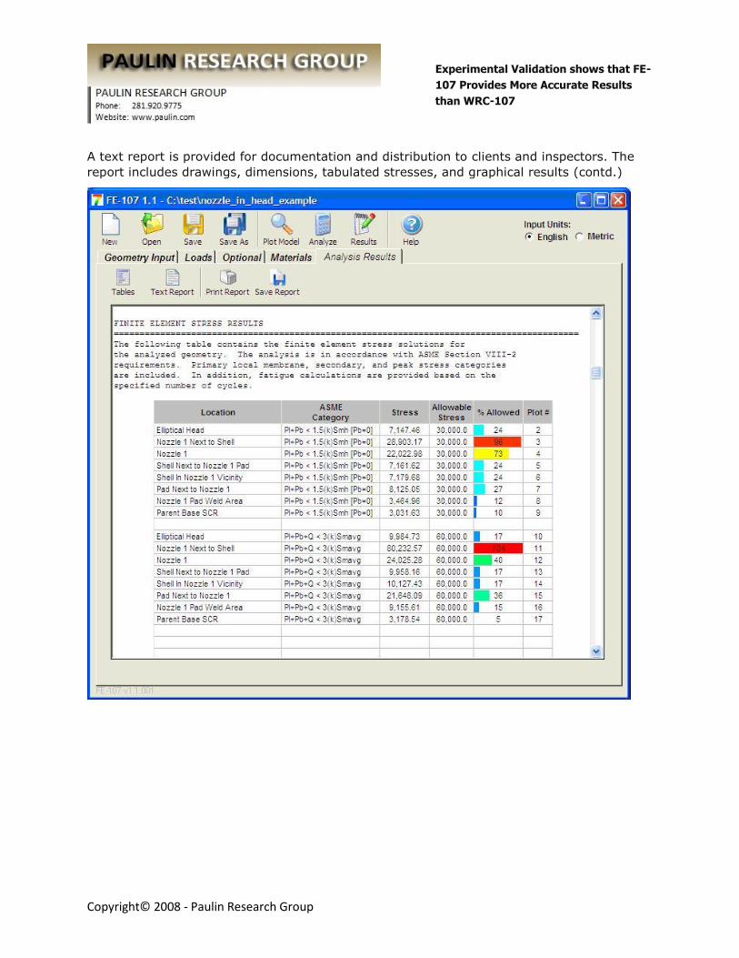
A text report is provided for documentation and distribution to clients and inspectors. The
report includes drawings, dimensions, tabulated stresses, and graphical results (contd.)
Experimental Validation shows that FE-
107 Provides More Accurate Results
than WRC-107
Copyright© 2008 - Paulin Research Group
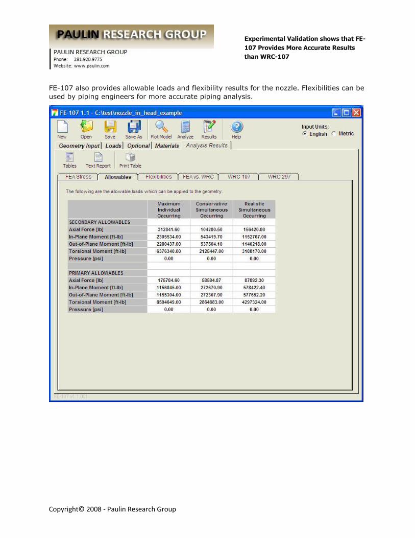
FE-107 also provides allowable loads and flexibility results for the nozzle. Flexibilities can be
used by piping engineers for more accurate piping analysis.

Experimental Validation shows that FE-
107 Provides More Accurate Results
than WRC-107
Copyright© 2008 - Paulin Research Group
FE-107 also provides allowable loads and flexibility results for the nozzle. Flexibilities can be
used by piping engineers for more accurate piping analysis. (contd.)
Experimental Validation shows that FE-
107 Provides More Accurate Results
than WRC-107
Copyright© 2008 - Paulin Research Group
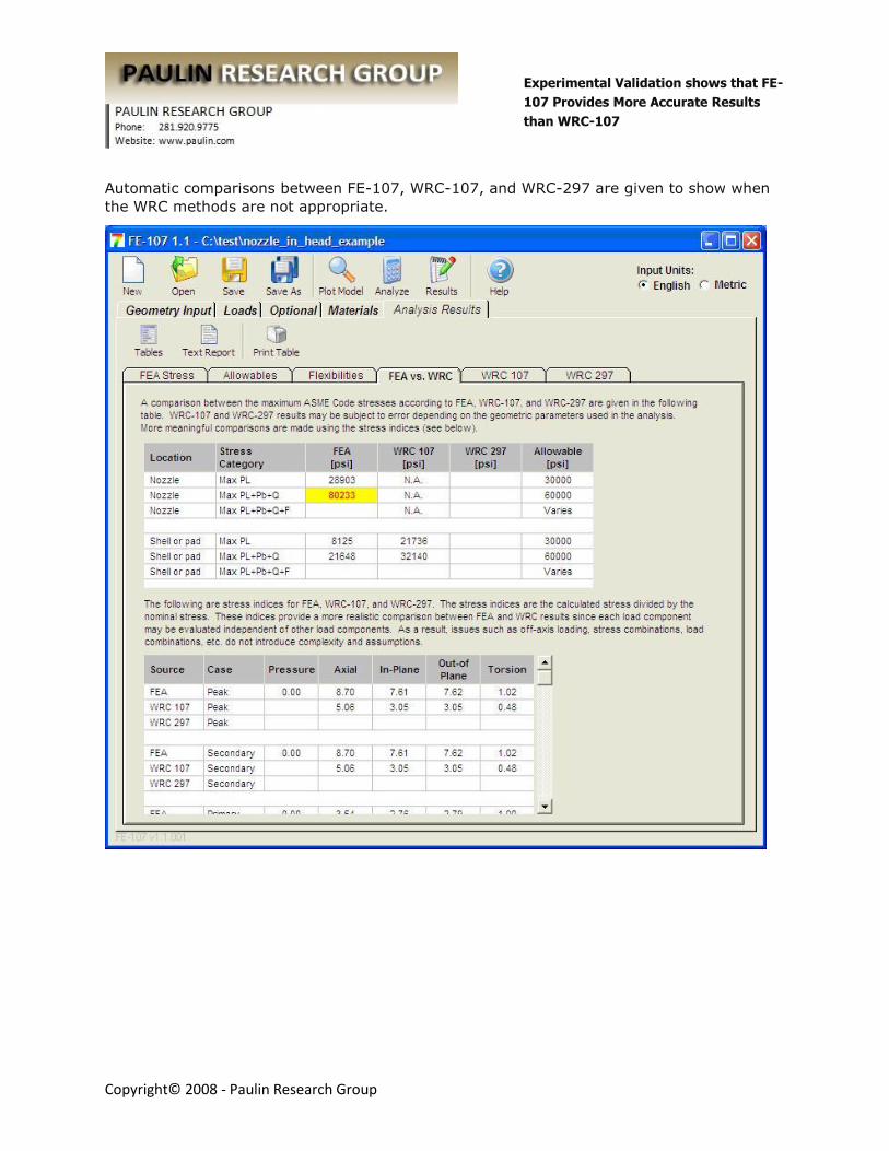
Automatic comparisons between FE-107, WRC-107, and WRC-297 are given to show when
the WRC methods are not appropriate.