fg7b-druid installer rev 1.4 · installers manual revision 1.4 12 september 2017 ... all other...
TRANSCRIPT

INSTALLERS MANUAL Revision 1.4 12 September 2017
GROUP OF COMPANIES
FG7B CONTROLLER for DRUID 25/28 NETWORKS

2
FG7B CONTROLLER: Table of Contents
INTRODUCTION…..……………………………………………………………………… 3
OPENING THE FG7B…...………………………………………………….……………. 3
HARDWARE…................................................................................. 4-6
PROGRAMMING THE FG7B ……….……………..…………………………………… 7-11
MAPPING…………………………………………………………………………………….. 12-15
FIRMWARE UPGRADE…………………………………………………………………… 16
DOCUMENT REVISION HISTORY……………..…………………………………….. 17

3
FG7B CONTROLLER: Introduction
INTRODUCTION The Nemtek FG7 platform is a platform used for providing a graphical interface and connectivity
to a network of Nemtek Energizers and Input/Output Cards (IO Cards). The platform may be configured with different internal printed circuit boards, and software, to
provide the required functionality.
Warning:
Test the functionality of the system after configuration and before commissioning.
OPENING THE FG7B
On the opposite side to the LCD display are two screws that need to be removed.
With the LCD facing you, slide the LCD gently to one side by approximately 15mm.
Leverage the LCD out as shown in the picture.
A green printed circuit board IOT1601 JM and a dark blue control unit are inside the unit.

4
FG7B CONTROLLER: HARDWARE
The IOT1601 JM board is responsible for generating the different supply voltages. The input
voltage is 12Vdc and is polarity protected. The board also monitors and process the different
communication signals before sending the information to the control unit. You will find jumpers, connecters and leds on the board for selecting, connecting and indicating.
The control unit host the software and has all communication ports on board.

5
FG7B CONTROLLER: Hardware
JUMPER SETTINGS Jumper setting as viewed with terminals at the bottom.
TTL Serial JP7 (2) To the left if serial TTL is selected (For Nemlink communication) To the right if RS 485 or RS 232 communication is required
RS485/RS232 JP8 (2) To the left for RS 485 communication
To the right for RS 232 communication
RS485out JP3 (1) Down to enable RS 485 transmitting (standard)
Up to disable RS 485 transmitting (nonstandard use)
RS485in JP2 (1) Up to enable RS485 receiving (standard)
Down to disable RS485 receiving (nonstandard use)
Line Bias JP1 (2) Up to have line bias (star configurations)
Down for no line bias (daisy chain configuration)
Watch Dog timer 1 JP6 (1) Down for auto reset with transmission failure of the control unit
Up for no auto reset of the control unit
Watch Dog timer 2 JP4 (1) Down for auto reset of the power supply with transmission
failure of the control unit Up for no auto reset of the power supply
CONNECTORS The connectors on the IOT1601JM board are self-explanatory. However, if communication will be made through a NemLink card, then the connector J7 should be used with the comms cable
supplied with the unit (jumper selection TTL Serial). Also note that the FG7-Druid does not
support RS485 multidrop, only daisy chain – so there is a RS485 OUT and a RS485 IN terminal.
The TAUT Wire terminal is not used in the FG7-Druid controller.
PUSH BUTTONS There are two push buttons on the green board. The one is marked “B3 PWR” (Power) and the
other “B3 RESET”. The B3 PWR button is used to manually power the control unit on and off, this
is usually required when programming the settings on the FG7-Druid. The B3 RESET button is used to manually reset the FG7-Druid Controller.

6
FG7B CONTROLLER: Hardware
LEDS There are 8 LEDs on the green board.
LED9 – If flashing, indicates transmission of data from the control unit to TTL SERIAL/RS232/485
LED8 – If flashing, indicates that the control unit is receiving data from TTL SERIAL/RS232/485
LED7 – Not used in FG7-Druid
LED6 – Not used in FG7-Druid
LED5 – When on, indicates control board heartbeat
LED4 – When flashing, indicates that the watchdog timer is operational LED3 – 5V supply indicator
LED2 – 3V3 supply indicator
The control unit hosts the software and gives outputs via the touch screen, HDMI, Ethernet or USB port. All other ports should not be used by the installer.
USB PORT The USB port is used for upgrading software, uploading site images, downloading logs and can also be used for a mouse, so that a pointer can be used on the touch screen display.
HDMI PORT The HDMI port is a standard micro-HDMI connector. To activate the HDMI port a shell script has
to be loaded (contact distributor for details) and the touchscreen ribbon cable has to be disconnected from connector LCD1 (brown ribbon cable). A USB mouse should be used for
operating the system when using an HDMI display.
ETHERNET PORT The Ethernet port is used for communication with Druid FenceProbe or third party software.
TOUCHSCREEN The touchscreen is the standard display used on the stand-alone units, without Druid FenceProbe
or third party software.

7
FG7B CONTROLLER: Programming the FG7B
PROGRAMMING THE FG7B-DRUID The FG7B-Druid should be programmed with the number of energizers as well as the IO cards in
the system.
If required a graphic site image can be loaded on the FG7B-Druid and zones (sectors) as well as
Gate lines can be drawn on the image.
CONFIGURE THE NUMBER OF ENERGIZERS ON THE NETWORK
1) On the FG7, press the PIN tab on the top screen and select▼ Installer, enter the
appropriate PIN number and press Enter. Check that Installer stays on the screen and
has not revert back to select.
2) Press the System tab on the top of the screen and use the ▼ and ▲ markers next to the
number of energizers to select the correct number of energizers in the network.
Press Save No of Energizers.
3) If jumper 4 and 6 are set to auto reset (normal operation), then after about two minutes
the application will restart. Otherwise one can push the B3-PWR button and this will close the application and after the Nemtek logo has disappeared from the screen you press the
B3-PWR button again to restart the unit. 4) Check under the system tab that the number of energizers is now correct.
CONFIGURE THE NUMBER OF IO CARDS ON THE NETWORK
1) On the FG7, press the PIN tab on the top screen and select▼ Installer, enter the
appropriate PIN number and press enter. Check that Installer stays on the screen and
has not revert back to select.
2) Press the System tab on the top of the screen and use the ▼ and ▲ markers next to the
number of IO cards to select the correct number of IO cards in the network. Press Save No of IO cards.
3) IF jumper 4 and 6 are set to auto reset (normal operation), then after about two minutes
the application will restart. Otherwise one can push the B3-PWR button and this will close the application and after the Nemtek logo has disappeared from the screen you press the
B3-PWR button again to restart the unit. 4) Check under the system tab that the number of IO cards is now correct.
8
FG7B CONTROLLER: Programming the FG7B
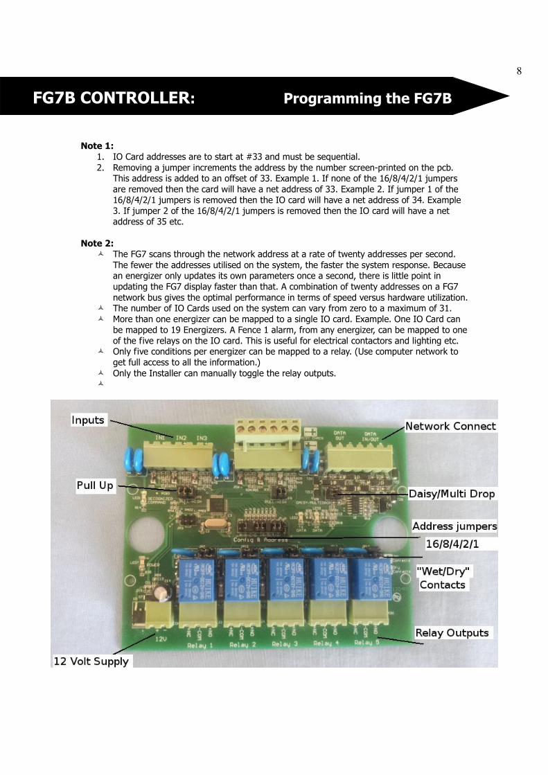
Note 1:
1. IO Card addresses are to start at #33 and must be sequential.
2. Removing a jumper increments the address by the number screen-printed on the pcb. This address is added to an offset of 33. Example 1. If none of the 16/8/4/2/1 jumpers
are removed then the card will have a net address of 33. Example 2. If jumper 1 of the
16/8/4/2/1 jumpers is removed then the IO card will have a net address of 34. Example
3. If jumper 2 of the 16/8/4/2/1 jumpers is removed then the IO card will have a net address of 35 etc.
Note 2: � The FG7 scans through the network address at a rate of twenty addresses per second.
The fewer the addresses utilised on the system, the faster the system response. Because an energizer only updates its own parameters once a second, there is little point in
updating the FG7 display faster than that. A combination of twenty addresses on a FG7
network bus gives the optimal performance in terms of speed versus hardware utilization. � The number of IO Cards used on the system can vary from zero to a maximum of 31.
� More than one energizer can be mapped to a single IO card. Example. One IO Card can
be mapped to 19 Energizers. A Fence 1 alarm, from any energizer, can be mapped to one
of the five relays on the IO card. This is useful for electrical contactors and lighting etc. � Only five conditions per energizer can be mapped to a relay. (Use computer network to
get full access to all the information.)
� Only the Installer can manually toggle the relay outputs. �

9
FG7B CONTROLLER: Programming the FG7B
SYSTEM TAB SETTINGS
Under the system tab there are a number of settings which can be selected by clicking on the setting required and the tick box next to the setting will then show a tick indicating that the
setting is selected. The following settings can be selected:
Audible alarm Alarm Sensor mode
Show sync loss
Extended comms timeout
Proxy
AUDIBLE ALARM The buzzer inside the FG7 is enabled when the Audible Alarm tick box is ticked. The buzzer will sound when there is an alarm or service condition. If unticked the buzzer is disabled.
ALARM SENSOR MODE
If the alarm sensor mode is ticked then alarm and service conditions will only show as long as the alarm or service condition is present. When the error clears the screen will show a good
condition again. If Audible alarm is ticked the buzzer will sound but will require a manual
energizer reset from the global screen.
SHOW SYNC LOSS
When ticked the FG7 will alarm, log and show under service that synchronization between
energizers in the system has been lost.
EXTENDED COMMS TIMEOUT
This feature might sometimes be required especially if radio frequency/microwaves links are used
in the system. They may show comms failures due to time delays in the links. By ticking
extended comms time a longer time is available before the comms alarm is triggered.
PROXY
If the FG7 is used as a proxy controller for third party software or computer application and you
do not want to display the site image on the screen of the FG7 then select proxy under the tab
screen. When ticked the default screen will only show the IP address of the FG7 and the software
version of the unit. There is also a tick box indicating that 3th party comms is taking place, the tick in the tick box will flash at half the integration frequency.

10
FG7B CONTROLLER: Programming the FG7B
FACTORY DEFAULT Under the system Tab you can reset the FG7 to Factory default settings by pressing the default
button the IP address will be reset to 10.0.0.20 and all pin setting will default back to the numbers as stated in the user manual.
LOADING A GRAPHIC SITE IMAGE
1) Load nemshell7BIMAGE on an USB stick (nemshell7BIMAGE is available from Nemtek or
its distributors)
2) Get a suitable image of your site and scale the image to about 370 x 370 pixels. Save the
image in a png format and call it image. 3) Load the image on the USB stick.
4) If you can access the USB port without removing the unit from its base than start the
unit otherwise remove the unit from its base for access to the USB port and then start the unit.
5) Go to the PIN tab and select Installer, enter the Installer code and press enter. Make sure it stays on Installer and does not go back to select
6) Place the USB stick in the USB port on the control board.
7) Go to the System tab and press firmware upgrade (the screen will go black and says
system login).
8) If jumper 4 and 6 are set to auto reset (normal operation), then after about two minutes the application will restart. Otherwise one can push the B3-PWR button and this will close
the application and after the Nemtek logo has disappeared from the screen you press the
B3-PWR button again to restart the unit. 9) Remove the stick and place the unit back in its base.
DRAWING THE ZONES AND GATES LINES
1) On the FG7B, press the PIN tab on the top screen and Select ▼ Installer. Enter the
appropriate PIN number and press Enter. Check that Installer stays on the screen and
has no revert back to Select. 2) Press the Image tab on the top of the screen.
3) Use the ▼ and ▲ keys under Energ# symbol to select the desired energizer.
4) Use the ▼ and ▲ keys under Zone# symbol to select the desired zone.
5) Press “Start” and touch the screen at the desired points corresponding to that sector.
Once the last point is reached press “Stop”. A maximum of eight points is permissible. Press “View” to see what your sector looks like. If unhappy with the result simply press
“Start” and repeat the procedure.
Please note that a USB mouse can be used to assist with drawing the lines.
6) A Gate can be associated with each energizer, but only has two points. Press “Gstrt” and
touch the screen at the start point and end point of the gate. Press “View” to confirm
your entry.

11
FG7B CONTROLLER: Programming the FG7B
7) You can randomly do all energizers, zones and gates using steps 3 to 6 above.
8) When you are happy with the zone and gate lines press “Save”
9) The system will automatically load this graphic layout on power-up. You may after entering Installer mode, edit any sector independently and then re-save.
10) The labels E1:Z1 (Energizer Address, Zone number) and E1:Z2 etc. are placed
automatically at the start of each fence sector.
SETTING THE IP ADDRESS
1) On the FG7, press the PIN tab on the top screen and select▼ Installer, enter the
appropriate PIN number and press enter. Check that Installer stays on the screen and
has not revert back to select.
2) Press the System tab on the top of the screen and use the ▼ and ▲ markers next to
the address boxes to set the correct IP address, Network Mask and Gateway address.
3) Press the Set IP Address button on the bottom of the screen and the new IP address will
be programmed into the FG7.
4) To ensure that the setting is correct ping the new IP address from a computer.
LCD CALIBRATION The touch screen display can be calibrated, this will be necessary if the screen is replaced or if it
is difficult to touch the buttons on the screen. If the touch position on the screen is too far out to
touch the LCD calibration button a USB mouse can also be used to recalibrate the screen otherwise a pen can be used.
1) On the FG7, press the PIN tab on the top screen and select▼ Installer, enter the
appropriate PIN number and press enter. Check that Installer stays on the screen and
has not revert back to select. 2) Press the system tab on the top of the screen and press the LCD calibration button. The
Nemtek screen should appear followed by the calibration screen 3) Touch the crosshair and a second crosshair will appear. Touch the second crosshair.
4) Carry one until all five crosshair markers are done. The unit will then automatically
reboot with the new calibration.
12
FG7B CONTROLLER Mapping
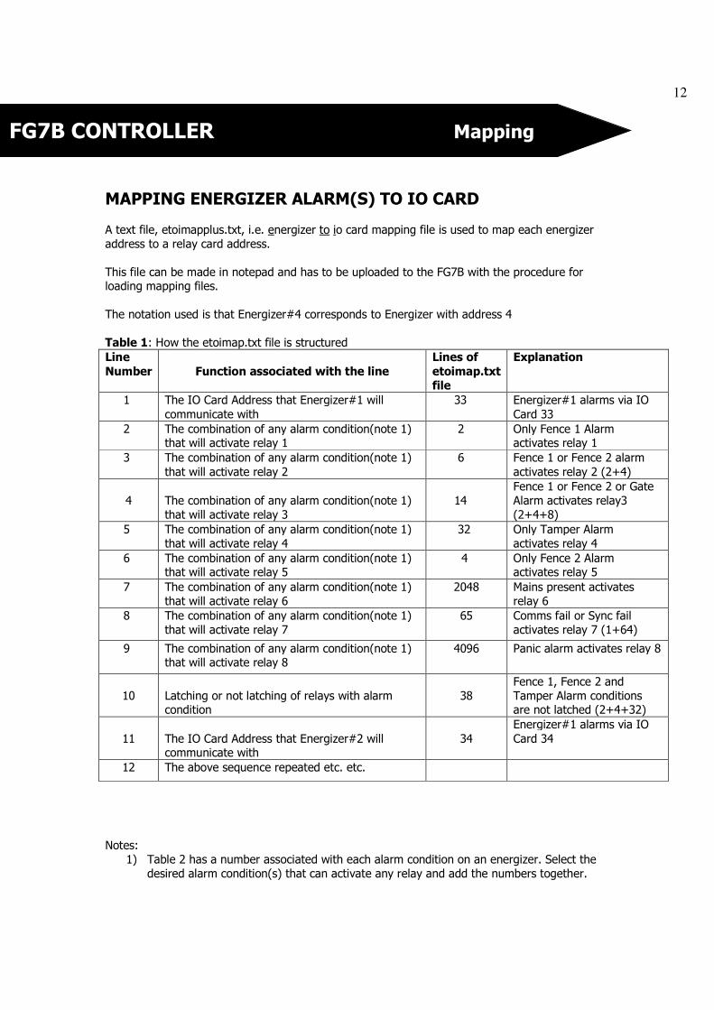
MAPPING ENERGIZER ALARM(S) TO IO CARD
A text file, etoimapplus.txt, i.e. energizer to io card mapping file is used to map each energizer
address to a relay card address.
This file can be made in notepad and has to be uploaded to the FG7B with the procedure for loading mapping files.
The notation used is that Energizer#4 corresponds to Energizer with address 4
Table 1: How the etoimap.txt file is structured
Line
Number
Function associated with the line
Lines of
etoimap.txt
file
Explanation
1 The IO Card Address that Energizer#1 will
communicate with
33 Energizer#1 alarms via IO
Card 33
2 The combination of any alarm condition(note 1) that will activate relay 1
2 Only Fence 1 Alarm activates relay 1
3 The combination of any alarm condition(note 1)
that will activate relay 2
6 Fence 1 or Fence 2 alarm
activates relay 2 (2+4)
4
The combination of any alarm condition(note 1)
that will activate relay 3
14
Fence 1 or Fence 2 or Gate
Alarm activates relay3
(2+4+8)
5 The combination of any alarm condition(note 1)
that will activate relay 4
32 Only Tamper Alarm
activates relay 4
6 The combination of any alarm condition(note 1) that will activate relay 5
4 Only Fence 2 Alarm activates relay 5
7 The combination of any alarm condition(note 1)
that will activate relay 6
2048 Mains present activates
relay 6
8 The combination of any alarm condition(note 1)
that will activate relay 7
65 Comms fail or Sync fail
activates relay 7 (1+64)
9 The combination of any alarm condition(note 1) that will activate relay 8
4096 Panic alarm activates relay 8
10
Latching or not latching of relays with alarm condition
38
Fence 1, Fence 2 and
Tamper Alarm conditions are not latched (2+4+32)
11
The IO Card Address that Energizer#2 will communicate with
34
Energizer#1 alarms via IO
Card 34
12 The above sequence repeated etc. etc.
Notes:
1) Table 2 has a number associated with each alarm condition on an energizer. Select the
desired alarm condition(s) that can activate any relay and add the numbers together.

13
FG7B CONTROLLER Mapping
2) If the relay must only be activated as long as the alarm condition persist (not latching) then select the energizer condition in table 2 and add the number together for all the
relays which must not latch. Zero implies everything is latching and an alarm condition
has to be reset manually after an alarm occurs.
3) There are two types of IO card available one with 5 programmable relays and one with 8 programmable relays. If the one with 5 relays is used then line 7,8 and 9 can be made 0.
Table 2: How the numbers are associated with each alarm state
Energizer State Number
COMMS FAIL 1
FENCE 1 ALARM 2
FENCE 2 ALARM 4
GATE ALARM 8
SERVICE ALARM 16
TAMPER ALARM 32
SYNC FAILURE 64
ZONE 1 ON 128
ZONE 1 HIGH VOLTAGE 256
ZONE 2 ON 512
ZONE 2 HIGH VOLTAGE 1024
MAINS PRESENT 2048
PANIC ALARM 4096
Multiple energizers addresses can communicate with single IO card addresses i.e. a fence alarm
on Zone 1 of any energizer could turn on a specific relay of one particular IO card and control
perimeter lighting. In this case line 8 in Table 1 would have a 33. Both Energizer#1 and
Energizer#2 would communicate with IO card #33.
The choice of relay number and energizer condition(s) is totally arbitrary. Not all the relays have
to be configured.

14
FG7B CONTROLLER Mapping
MAPPING NEMTEK IO CARDS TO ENERGIZER(S) Inputs on a Nemtek IO card may be used to control a specific energizer or all i.e. global
energizers on a network. A text file, itoemap.txt, i.e. io card to energizer mapping file, is used to map each IO card address to an energizer.
This file can be made in notepad and has to be uploaded to the FG7B with the procedure for
loading mapping files.
TABLE 3: How the itoemap.txt file is structured
Line Number
Function Associated with the line
Lines of itoe.txt file
Explanation
1
The energizer address that IO
card#33 will communicate with (unless global)
1 Energizer#1
2 Energizer specific inputs from this IO
card (note 3 and 5)
131
Input 1 from IO
card#33 will turn On/Off Zone 1. Input
2 will turn On/Off
Zone 2 of energizer#1
(1+2+128)
3 Global Energizer inputs from this IO
card (note 3 and 5)
176
Input 5 from IO card#33 will turn
On/Off all energizers.
Input 6 will turn all energizer in HV/LV
mode (16+32+128)
4 Inputs that are valid on this IO card
(note 4) 51 Inputs 1,2,5 and 6
are used
(1+2+16+32)
5 The Energizer Address that IO
card#34 will communicate with
(unless global)
2 Energizer#2
6 The above sequence repeated etc.
etc.
Notes:
4) Table 4 has a number associated with each IO card input. 5) Select the appropriate numbers and add them for the inputs to be recognized. If the
number is set to 0 the all inputs are ignored.
6) This number must be added when using either a Selective energizer control or Global energizer control in rows 2 and 3 of Table 3. I.e. if the total number is less than 128 for
a given row, then that particular row will be ignored.
7) Global inputs and specific inputs cannot be used on the same IO card so either line 2 or
line 3 should be zero.

15
FG7B CONTROLLER Mapping
Warning
1) If multiple IO Cards are used, with multiple identical global inputs enabled you could end up with energizers turning On and Off every second. If the one global input dictates that
all energizers should be On and the other global input on another IO card dictates that
all energizers should be Off, you will have a non-functioning network.
TABLE 4: How the numbers relate to the IO Card Inputs
INPUT INPUT FUNCTION NUMBER
Input 1
ZONE 1 ON/OFF
1
Input 2 ZONE 2 ON/OFF 2
Input 3 ZONE 1 HIGH/LOW VOLTAGE 4
Input 4 ZONE 2 HIGH/LOW VOLTAGE 8
Input 5 GLOBAL ON/OFF 16
Input 6 GLOBAL HIGH/LOW VOLTAGE 32
ADD SEE NOTE 5 128
Input 7 Can only be utilized through application software
Input 8 Can only be utilized through application software
LOADING A MAPPING FILE Requirements:
Flash drive loaded with nemshell7BText1.sh and with folder NemText
Inside folder NemText place etoimapplus.txt and/or itoemap.txt (these two files should be made
in Notepad)
Procedure: 1) Connect power to the FG7 unit.
2) Place the flash drive in the USB connector of the FG7 unit ( make sure there is only one
nemshell on the flash drive)
3) On the top of the screen go to PIN and enter installer pin
4) Go to the system tab.
5) Press upgrade
6) Press the PWR button on the FG7. Wait until the Nemtek logo has disappeared and the
screen has gone black.
7) Press the PWR button on the FG7
8) Wait until the Display has come back on then remove the Flash drive.

16
FG7B CONTROLLER Firmware upgrade
FIRMWARE UPGRADE
1) Load on a USB stick the latest available software for the FG7B control unit. The file
normally is called nemtekfg7BDruid??? where ??? normally is a number indicating the
version. The latest version will be available from Nemtek or its distributors.
2) If you can access the USB port without removing the unit from its base than start the unit otherwise remove the unit from its base for access to the USB port and then start
the unit.
3) Go to the PIN tab and select Installer, enter the Installer code and press enter.
Make sure it stays on Installer and does not go back to Select.
4) Place the USB stick in the USB port on the control board.
5) Go to the System tab and check the version number and then press firmware upgrade
(the screen will go black and says system login). 6) If jumper 4 and 6 are set to auto reset (normal operation), then after about two minutes
the application will restart. Otherwise one can push the B3-PWR button and this will close
the application and after the Nemtek logo has disappeared from the screen you press the B3-PWR button again to restart the unit.
7) Go back to the System tab and check that the new version has been loaded. 8) Remove the stick and place the unit back in its base.

17
FG7B CONTROLLER Document Revision History
DOCUMENT REVISION HISTORY
Revision 1.0
10 Feb 2017
Revision 1.1 8 March 2017
Added IP addressing and screen calibration
Revision 1.2
9 May 2017
Mapping and procedures added
Revision 1.3 20 July 2017
Added Sync fail, Extended Comms timeout, Alarm sensor mode and proxy options Changed IO mapping Global and specific on different IO cards.
Revision 1.4
12 September 2017
Changes to allow for an 8 input and 8 output relay card
End of document

18