formula blast cabinet range - s3-eu-west-1.amazonaws.com
TRANSCRIPT

Guyson International Limited Snaygill Industrial Estate Keighley Road Skipton North Yorkshire BD23 2QR
Tel: 01756 799911 E-mail: [email protected] Website: www.guyson.co.uk
Formula Blast Cabinet Range
Operating & Maintenance Instructions
Operation & Maintenance Manual
Issue: 08 A6ML0041 – Formula Blast Cabinet Instruction Manual Date: 07/2021 Page: 2
Table of contents 1. Introduction ......................................................................................................................................... 3
1.1 Safety recommendations .............................................................................................................. 3 1.2 Electrical specification .................................................................................................................. 3
2. Data sheet ........................................................................................................................................... 4 2.1 General information ...................................................................................................................... 4 2.2 Air consumption tables ................................................................................................................. 4
2.2.1 Air flow measured in m³/hr at different pressures measured in bar ....................................... 4 2.2.2 Air flow measured in CFM at different pressures measured in psi ........................................ 4
3. Installation ........................................................................................................................................... 5 3.1 Location ........................................................................................................................................ 5 3.2 Assembly ...................................................................................................................................... 5
3.2.1 Compressed air connections ................................................................................................. 6 3.2.2 Electrical connections ............................................................................................................ 7
4. Testing installation .............................................................................................................................. 8 4.1 Testing installation procedure ....................................................................................................... 8 4.2 Media levels .................................................................................................................................. 9
4.2.1 Adding media to hopper ......................................................................................................... 9 5. Machine settings ............................................................................................................................... 10
5.1 Blast settings............................................................................................................................... 10 5.1.1 Blasting pressure ................................................................................................................. 10 5.1.2 Media pick-up tube ............................................................................................................... 11 5.1.3 Stand-off distance ................................................................................................................ 12 5.1.4 Angle of blasting ................................................................................................................... 12
5.2 Extraction settings ...................................................................................................................... 13 5.2.1 Dust collector ....................................................................................................................... 13
6. Operation .......................................................................................................................................... 14 6.1 Operating procedure ................................................................................................................... 14
7. Maintenance ...................................................................................................................................... 15 7.1 Daily ............................................................................................................................................ 16
7.1.1 Breather pad ........................................................................................................................ 17 7.1.2 Viewing window .................................................................................................................... 18 7.1.3 Empty dust collector bin ....................................................................................................... 18 7.1.4 Filter cleaning ....................................................................................................................... 19
7.1.4.1 Replacing the filter sleeves on an F21/F41 dust collector ............................................ 20 7.1.5 Compressed air filter ............................................................................................................ 20 7.1.6 Hoses ................................................................................................................................... 21 7.1.7 Blast nozzles ........................................................................................................................ 22
7.1.7.1 400 Blast gun ................................................................................................................ 22 7.1.7.2 400 Trigger gun ............................................................................................................. 22 7.1.7.3 Blast nozzle ................................................................................................................... 22 7.1.7.4 Airjet .............................................................................................................................. 24 7.1.7.5 Media entry ................................................................................................................... 24
7.1.8 Door seals ............................................................................................................................ 24 7.1.9 Topping up media ................................................................................................................ 24
7.2 Weekly ........................................................................................................................................ 25 7.2.1 Gauntlets .............................................................................................................................. 25
7.3 Monthly ....................................................................................................................................... 26 7.3.1 Emptying media ................................................................................................................... 26
8. FAQ’s ................................................................................................................................................ 27 9. Spares and servicing ......................................................................................................................... 28
9.1 Recommended spares list .......................................................................................................... 29 10. Appendices ..................................................................................................................................... 31

Operation & Maintenance Manual
Issue: 08 A6ML0041 – Formula Blast Cabinet Instruction Manual Date: 07/2021 Page: 3
1. Introduction This manual should be regarded as part of the product and must be retained for the life of the machine. The manual must be passed to any subsequent owners of the machine. Any amendments should be attached to the original manual. Machine identification and serial number can be found on the identification plate fixed to the machine body. 1.1 Safety recommendations Users of Guyson equipment are advised to make sure they have identified any hazards associated with their specific air washing processes, including: Use of compressed air Fire/explosion risks Suitable procedures for dealing with fire hazards Production of carcinogenic or toxic substances from component surface removal Any other known hazards Users are responsible for ensuring that they have implemented any current regulatory requirements, e.g. COSHH, to deal with any potential risks and/or hazards associated with their processes. ATEX ZONE DESIGNATION The ATEX Directives 2014/34/EU (product requirements) and 99/92/EC (user requirements) are implemented by the Equipment and Protective Systems intended for use in potentially explosive Atmospheres Regulations 1996 (EPS and the Dangerous Substances and Explosive Atmosphere Regulations 2002 (DSEAR) respectively. We are able to provide equipment that is suitable for use in a hazardous area, and/or equipment that is suitable for use when a hazardous area is created within a system, but it is the end users’ responsibility to classify the area in which the equipment is to be used and/or the explosivity of any internal atmosphere created within the system. This is defined in Section 2, Article 3 to 9 of the 99/92/EC Directive (ATEX 137). Unless we have been advised otherwise, we have to assume that the equipment will be used in an area that is not classified as potentially explosive, and uses a process which will not create an explosive atmosphere within the equipment. 1.2 Electrical specification Electrical wiring on Guyson equipment conforms to: BSEN 60204-1:2006 IEC 60204-1:2005
Operation & Maintenance Manual
Issue: 08 A6ML0041 – Formula Blast Cabinet Instruction Manual Date: 07/2021 Page: 4
2. Data sheet 2.1 General information
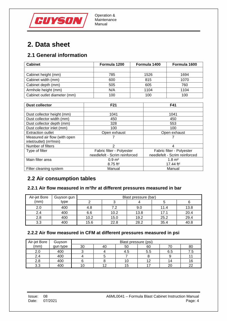
Cabinet Formula 1200 Formula 1400 Formula 1600 Cabinet height (mm) 785 1526 1694 Cabinet width (mm) 600 815 1070 Cabinet depth (mm) 505 605 760 Armhole height (mm) N/A 1104 1104 Cabinet outlet diameter (mm) 100 100 100
Dust collector F21 F41 Dust collector height (mm) 1041 1041 Dust collector width (mm) 450 450 Dust collector depth (mm) 328 553 Dust collector inlet (mm) 100 100 Extraction outlet Open exhaust Open exhaust Measured air flow (with open inlet/outlet) (m³/min)
7 7
Number of filters 2 4 Type of filter Fabric filter - Polyester
needlefelt - Scrim reinforced Fabric filter - Polyester
needlefelt - Scrim reinforced Main filter area 0.9 m²
8.75 ft² 1.8 m²
17.44 ft² Filter cleaning system Manual Manual 2.2 Air consumption tables 2.2.1 Air flow measured in m³/hr at different pressures measured in bar
Air-jet Bore (mm)
Guyson gun type
Blast pressure (bar) 2 3 4 5 6
2.0 400 4.8 7.2 9.0 11.4 13.8 2.4 400 6.6 10.2 13.8 17.1 20.4 2.8 400 10.2 15.0 19.2 25.2 29.4 3.3 400 15.6 22.8 28.2 35.4 40.8
2.2.2 Air flow measured in CFM at different pressures measured in psi
Air-jet Bore (mm)
Guyson gun type
Blast pressure (psi) 30 40 50 60 70 80
2.0 400 3 4 4.5 5.5 6.5 7.5 2.4 400 4 5 7 8 9 11 2.8 400 6 8 10 12 14 16 3.3 400 10 12 15 17 20 22
Operation & Maintenance Manual
Issue: 08 A6ML0041 – Formula Blast Cabinet Instruction Manual Date: 07/2021 Page: 5
3. Installation The system comprises of the following unit:
• Formula Cabinet
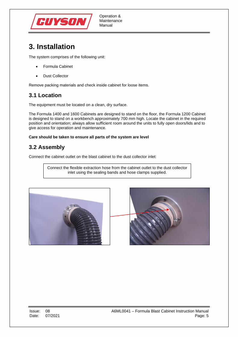
• Dust Collector Remove packing materials and check inside cabinet for loose items. 3.1 Location The equipment must be located on a clean, dry surface. The Formula 1400 and 1600 Cabinets are designed to stand on the floor, the Formula 1200 Cabinet is designed to stand on a workbench approximately 700 mm high. Locate the cabinet in the required position and orientation; always allow sufficient room around the units to fully open doors/lids and to give access for operation and maintenance. Care should be taken to ensure all parts of the system are level 3.2 Assembly Connect the cabinet outlet on the blast cabinet to the dust collector inlet:
Connect the flexible extraction hose from the cabinet outlet to the dust collector inlet using the sealing bands and hose clamps supplied.
Operation & Maintenance Manual
Issue: 08 A6ML0041 – Formula Blast Cabinet Instruction Manual Date: 07/2021 Page: 6
3.2.1 Compressed air connections
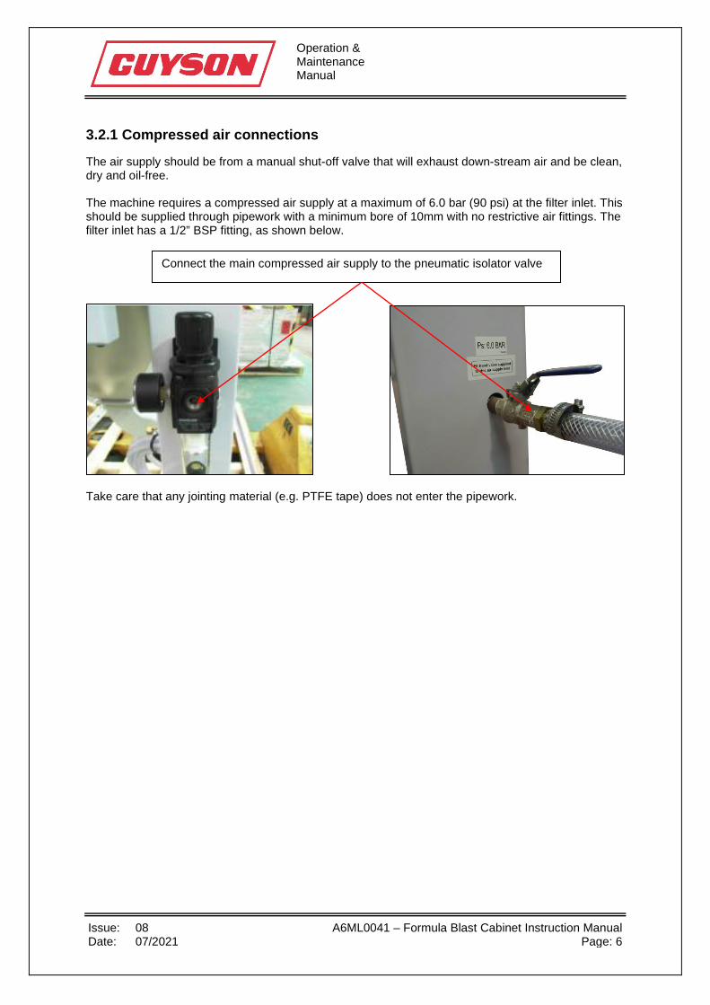
The air supply should be from a manual shut-off valve that will exhaust down-stream air and be clean, dry and oil-free. The machine requires a compressed air supply at a maximum of 6.0 bar (90 psi) at the filter inlet. This should be supplied through pipework with a minimum bore of 10mm with no restrictive air fittings. The filter inlet has a 1/2” BSP fitting, as shown below.
Take care that any jointing material (e.g. PTFE tape) does not enter the pipework.
Connect the main compressed air supply to the pneumatic isolator valve
Operation & Maintenance Manual
Issue: 08 A6ML0041 – Formula Blast Cabinet Instruction Manual Date: 07/2021 Page: 7
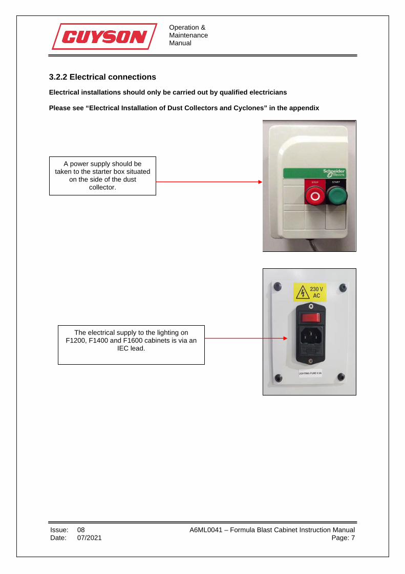
3.2.2 Electrical connections
Electrical installations should only be carried out by qualified electricians Please see “Electrical Installation of Dust Collectors and Cyclones” in the appendix
A power supply should be taken to the starter box situated
on the side of the dust collector.
The electrical supply to the lighting on F1200, F1400 and F1600 cabinets is via an
IEC lead.

Operation & Maintenance Manual
Issue: 08 A6ML0041 – Formula Blast Cabinet Instruction Manual Date: 07/2021 Page: 8
4. Testing installation 4.1 Testing installation procedure After completing all the connections the cabinet operation should be checked. Do not open the air supply at this stage.
• Switch on main electrical power supply
• Switch on cabinet light
• Start the dust collector:
o The direction of the impellor motor should be checked visually against the arrow on the motor. If rotation is in the wrong direction on the single phase motor, then Guyson International should be contacted for more information.
NOTE: Air will flow from the outlet even if the fan rotation is wrong, but only at a low level, so rotation must be checked visually.
On a F21/F41 dust collector the motor is inside. Unclip the catches and remove the front panel to check its rotation.
The best way to do this task is by starting then stopping the dust collector and watch the fan as it slows down.
• Turn on the air supply by opening the main air valve
• Set pressure regulator to required air wash pressure
• Check all in-line connections for leaks and possible blockages
• Insert both arms through the armhole entries
• Depress the foot pedal (or trigger valve for Formula 1200)
• Check for a steady air blast from the gun and for possible leaks
• Remove arms from gauntlets, isolate cabinet from compressed air supply and ensure all
compressed air is discharged from the system, open cabinet and add blast media.
Operation & Maintenance Manual
Issue: 08 A6ML0041 – Formula Blast Cabinet Instruction Manual Date: 07/2021 Page: 9
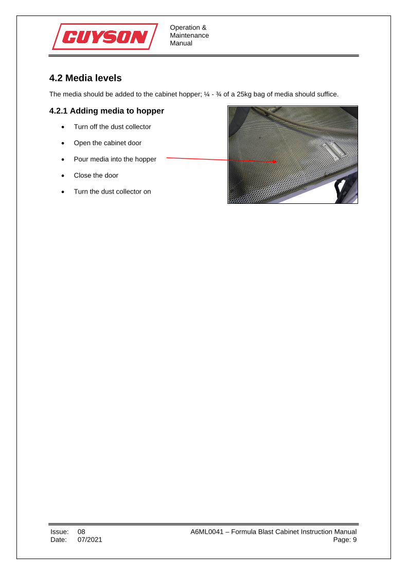
4.2 Media levels The media should be added to the cabinet hopper; ¼ - ¾ of a 25kg bag of media should suffice. 4.2.1 Adding media to hopper
• Turn off the dust collector
• Open the cabinet door
• Pour media into the hopper
• Close the door
• Turn the dust collector on
Operation & Maintenance Manual
Issue: 08 A6ML0041 – Formula Blast Cabinet Instruction Manual Date: 07/2021 Page: 10
5. Machine settings 5.1 Blast settings The blast settings should be set in the order they appear in the following sections. 5.1.1 Blasting pressure
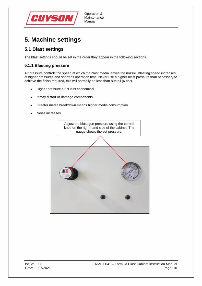
Air pressure controls the speed at which the blast media leaves the nozzle. Blasting speed increases at higher pressures and shortens operation time. Never use a higher blast pressure than necessary to achieve the finish required, this will normally be less than 80p.s.i (6 bar).
• Higher pressure air is less economical
• It may distort or damage components
• Greater media breakdown means higher media consumption
• Noise increases
Adjust the blast gun pressure using the control knob on the right-hand side of the cabinet. The
gauge shows the set pressure.

Operation & Maintenance Manual
Issue: 08 A6ML0041 – Formula Blast Cabinet Instruction Manual Date: 07/2021 Page: 11
5.1.2 Media pick-up tube
The setting of the pick-up tube in the media box has a significant effect on the blasting performance. Adjustment varies with the media density, with denser media requiring more air to circulate them. The greater the flow of media from the mixer box to the blast gun, the higher the rate of wear on media hose, blast nozzle.
• Check that there is a supply of free-flowing, dry media to the mixer box
• With compressed air flowing through the blast gun gradually move the pick-up tube into the mixer box with the chamfer facing upwards while a colleague watches the media flow from the nozzle.
The pick-up tube is in the right position when you are just able to see the media stream leaving the nozzle. If the media stream is intermittent then the pick-up tube has been pushed too far in.
o Moving the pick-up tube out decreases media flow
o Moving the pick-up tube in increases media flow
• Lock the pick-up tube in place with the retaining screw
• Further adjustment should not be needed whilst using the same media
Pick-up tube
Retaining screw
Increase media flow Decrease
media flow
O-ring is used to mark position of the pickup tube in the mixer box.
This allows the tube to be reinserted at the same position.
Operation & Maintenance Manual
Issue: 08 A6ML0041 – Formula Blast Cabinet Instruction Manual Date: 07/2021 Page: 12
5.1.3 Stand-off distance
This is the distance of the gun nozzle from the component. The stand-off distance should not normally be reduced below 50 mm as media from the nozzle will be deflected or slowed down by media ricocheting from the surface being blasted. The impact of the media can be affected by the stand-off distance and the air pressure. The type of media will influence this but a larger blast area may be achieved by increasing both the stand-off distance and the blast air pressure. 5.1.4 Angle of blasting
The optimum angle for blasting for surface finishing is between 90 and 60 degrees to the horizontal. Shallower angles can cause surface damage or compromise material properties. Greater angles than this can be used for deposit removal where the surface finish is not critical and with softer media. Blast guns should be angled to minimise interference between the outputs from different guns. This will avoid disrupting the speed and direction of media between nozzle and component. Always position guns pointing away from any cabinet openings; this minimises the risk of media being blasted out of the cabinet.
Operation & Maintenance Manual
Issue: 08 A6ML0041 – Formula Blast Cabinet Instruction Manual Date: 07/2021 Page: 13
5.2 Extraction settings 5.2.1 Dust collector
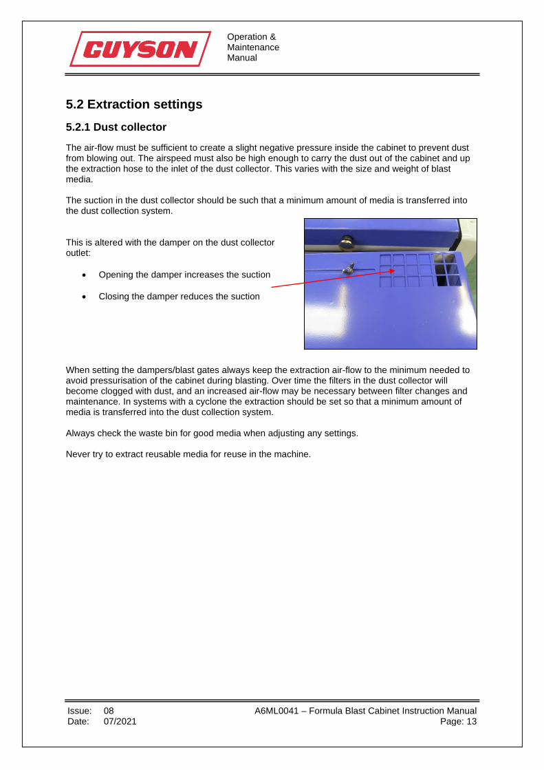
The air-flow must be sufficient to create a slight negative pressure inside the cabinet to prevent dust from blowing out. The airspeed must also be high enough to carry the dust out of the cabinet and up the extraction hose to the inlet of the dust collector. This varies with the size and weight of blast media. The suction in the dust collector should be such that a minimum amount of media is transferred into the dust collection system. This is altered with the damper on the dust collector outlet:
• Opening the damper increases the suction
• Closing the damper reduces the suction When setting the dampers/blast gates always keep the extraction air-flow to the minimum needed to avoid pressurisation of the cabinet during blasting. Over time the filters in the dust collector will become clogged with dust, and an increased air-flow may be necessary between filter changes and maintenance. In systems with a cyclone the extraction should be set so that a minimum amount of media is transferred into the dust collection system. Always check the waste bin for good media when adjusting any settings. Never try to extract reusable media for reuse in the machine.

Operation & Maintenance Manual
Issue: 08 A6ML0041 – Formula Blast Cabinet Instruction Manual Date: 07/2021 Page: 14
6. Operation 6.1 Operating procedure
• Perform daily maintenance tasks (see section 7.1)
• Switch on main electrical power supply
• Switch on cabinet light
• Start the dust collector
• Turn on the air supply by opening the main air valve
• Ensure any component is grease-free and dry before blasting
• Open the cabinet door
• Place component in cabinet
• Position the blast gun so that they will be easily reached when using the gauntlets/gloves and sleeves
• Close the cabinet door securely
• Insert both arms through the armhole entries
• Depress the foot pedal/trigger valve. Doors will lock and media will exit from the gun nozzle
• Move the nozzle jet across the component surface at a suitable distance, refer to blast gun
settings (see section 5.1.3)
• The component should be blasted evenly
• When the blasting is complete, release the foot pedal/trigger valve. Door interlocks will time out.
• The door can now be opened, and the component can be removed for inspection
• Further blasting may be necessary, or an adjustment to one or more of the machine or blast
settings (see section 5.1)

Operation & Maintenance Manual
Issue: 08 A6ML0041 – Formula Blast Cabinet Instruction Manual Date: 07/2021 Page: 15
7. Maintenance The frequency of any maintenance schedule and the replacement of parts are determined by the amount of use and operating conditions. Maintenance intervals will be determined by experience of machine-use over time. The following periods are recommended for initial trial periods until a pattern is established.
ENSURE ALL AIR SUPPLIES ARE TURNED OFF AND THE SYSTEM IS FULLY EXHAUSTED BEFORE PERFORMING ANY MAINTENANCE
THE DUST COLLECTOR SHOULD BE FULLY ISOLATED BEFORE PERFORMING ANY MAINTENANCE. A LOCK-OUT AND TAG PROCEDURE SHOULD BE IN PLACE TO PREVENT THE MACHINE FROM BEING STARTED PRIOR TO THE COMPLETION OF MAINTENANCE.
PPE: GUYSON RECOMMENDS THAT AS A MINIMUM, OPERATIVES SHOULD USE A DUST MASK AND SAFETY GLASSES WHEN PERFORMING MAINTENANCE OF ANY SORT. REFERENCE SHOULD BE MADE TO THE MATERIAL SAFETY DATA SHEET OF THE MEDIA BEING USED FOR ANY SPECIFIC PPE REQUIRED.

Operation & Maintenance Manual
Issue: 08 A6ML0041 – Formula Blast Cabinet Instruction Manual Date: 07/2021 Page: 16
7.1 Daily • Inspect breather pad (see section 7.1.1)
• Inspect the viewing window and anti-frost sheet (see section 7.1.2)
• Empty dust collector bin (see section 7.1.3)
• Clean the filters every four working hours (see section 7.1.4)
• Check compressed air filter (see section 7.1.5)
• Check hoses for signs of wear or damage (see section 7.1.6)
• Check blast nozzles for wear (see section 7.1.7)
• Check door seals and replace if necessary (see section 7.1.8)
• Check media levels regularly and top up if necessary (see section 7.1.9)
Operation & Maintenance Manual
Issue: 08 A6ML0041 – Formula Blast Cabinet Instruction Manual Date: 07/2021 Page: 17
7.1.1 Breather pad
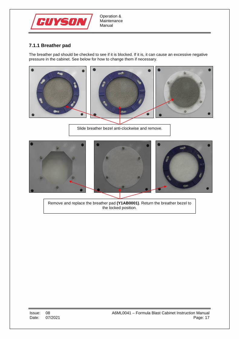
The breather pad should be checked to see if it is blocked. If it is, it can cause an excessive negative pressure in the cabinet. See below for how to change them if necessary.
Remove and replace the breather pad (Y1AB0001). Return the breather bezel to the locked position.
Slide breather bezel anti-clockwise and remove.
Operation & Maintenance Manual
Issue: 08 A6ML0041 – Formula Blast Cabinet Instruction Manual Date: 07/2021 Page: 18
7.1.2 Viewing window
7.1.3 Empty dust collector bin
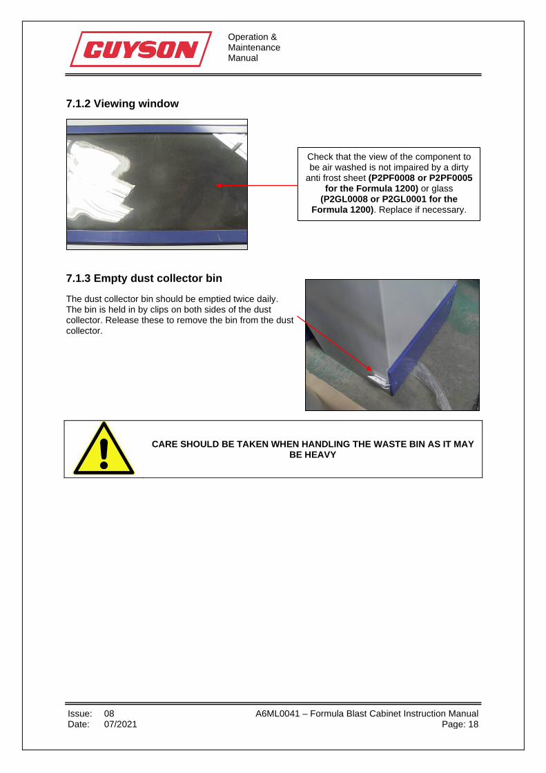
The dust collector bin should be emptied twice daily. The bin is held in by clips on both sides of the dust collector. Release these to remove the bin from the dust collector.
CARE SHOULD BE TAKEN WHEN HANDLING THE WASTE BIN AS IT MAY BE HEAVY
Check that the view of the component to be air washed is not impaired by a dirty
anti frost sheet (P2PF0008 or P2PF0005 for the Formula 1200) or glass
(P2GL0008 or P2GL0001 for the Formula 1200). Replace if necessary.
Operation & Maintenance Manual
Issue: 08 A6ML0041 – Formula Blast Cabinet Instruction Manual Date: 07/2021 Page: 19
7.1.4 Filter cleaning
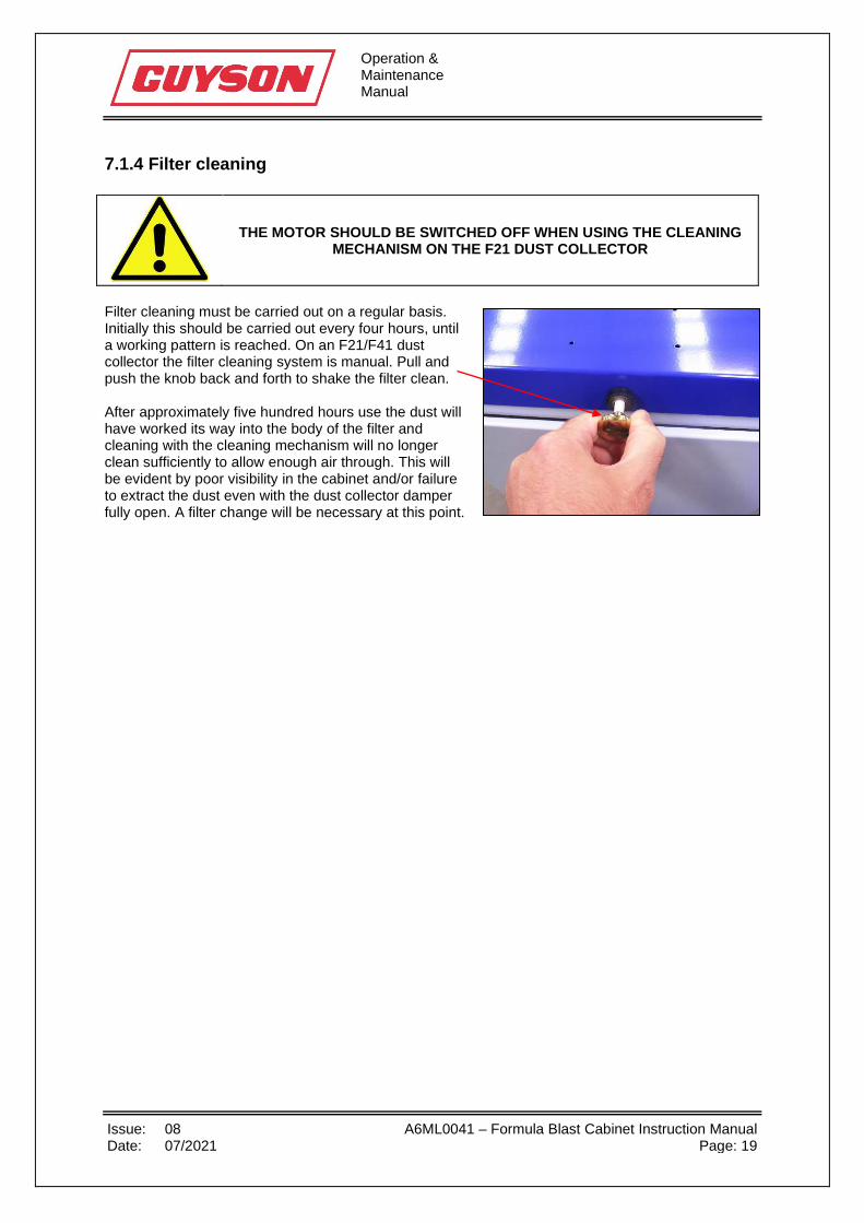
Filter cleaning must be carried out on a regular basis. Initially this should be carried out every four hours, until a working pattern is reached. On an F21/F41 dust collector the filter cleaning system is manual. Pull and push the knob back and forth to shake the filter clean. After approximately five hundred hours use the dust will have worked its way into the body of the filter and cleaning with the cleaning mechanism will no longer clean sufficiently to allow enough air through. This will be evident by poor visibility in the cabinet and/or failure to extract the dust even with the dust collector damper fully open. A filter change will be necessary at this point.
THE MOTOR SHOULD BE SWITCHED OFF WHEN USING THE CLEANING MECHANISM ON THE F21 DUST COLLECTOR
Operation & Maintenance Manual
Issue: 08 A6ML0041 – Formula Blast Cabinet Instruction Manual Date: 07/2021 Page: 20
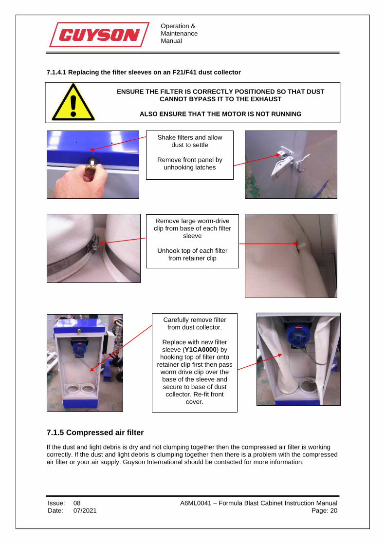
7.1.4.1 Replacing the filter sleeves on an F21/F41 dust collector
ENSURE THE FILTER IS CORRECTLY POSITIONED SO THAT DUST CANNOT BYPASS IT TO THE EXHAUST
ALSO ENSURE THAT THE MOTOR IS NOT RUNNING
7.1.5 Compressed air filter
If the dust and light debris is dry and not clumping together then the compressed air filter is working correctly. If the dust and light debris is clumping together then there is a problem with the compressed air filter or your air supply. Guyson International should be contacted for more information.
Shake filters and allow dust to settle
Remove front panel by
unhooking latches
Remove large worm-drive clip from base of each filter
sleeve
Unhook top of each filter from retainer clip
Carefully remove filter from dust collector.
Replace with new filter sleeve (Y1CA0000) by
hooking top of filter onto retainer clip first then pass worm drive clip over the base of the sleeve and secure to base of dust collector. Re-fit front
cover.
Operation & Maintenance Manual
Issue: 08 A6ML0041 – Formula Blast Cabinet Instruction Manual Date: 07/2021 Page: 21
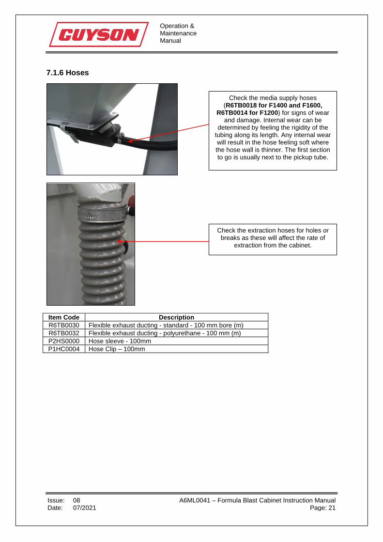
7.1.6 Hoses
Item Code Description R6TB0030 Flexible exhaust ducting - standard - 100 mm bore (m) R6TB0032 Flexible exhaust ducting - polyurethane - 100 mm (m) P2HS0000 Hose sleeve - 100mm P1HC0004 Hose Clip – 100mm
Check the extraction hoses for holes or breaks as these will affect the rate of
extraction from the cabinet.
Check the media supply hoses (R6TB0018 for F1400 and F1600,
R6TB0014 for F1200) for signs of wear and damage. Internal wear can be
determined by feeling the rigidity of the tubing along its length. Any internal wear will result in the hose feeling soft where the hose wall is thinner. The first section to go is usually next to the pickup tube.

Operation & Maintenance Manual
Issue: 08 A6ML0041 – Formula Blast Cabinet Instruction Manual Date: 07/2021 Page: 22
7.1.7 Blast nozzles
7.1.7.1 400 Blast gun
7.1.7.2 400 Trigger gun
9
8
10
6
11
2
3 4 5 1
7
Pos Item Code Description 1 400 Gun body 2 D2BA0001 6.4mm Ceramic nozzle 2 D2BA0004 6.4mm Tungsten nozzle 3 D2AA0007 Nozzle locknut 4 P1WS0038 Nozzle washer 5 P2GT0012 Nozzle grommet 6 D1AA0000 2.0mm Airjet 6 D1AA0001 2.4mm Airjet 6 D1AA0002 2.8mm Airjet 7 P1WS0037 Airjet gasket 8 P2SG0000 Airjet coil spring 9 D2AA0008 Top nut 10 P4CG0001 ¼” Hosetail x 10mm 11 P4CG0002 Media entry 3/8” x 16mm
1
2
3 4 5
6
7 8 9
10
11
12
13
Pos Item Code Description 1 400 Gun body 2 D2BA0001 6.4mm Ceramic nozzle 2 D2BA0004 6.4mm Tungsten nozzle 3 D2AA0007 Nozzle locknut 4 P1WS0038 Nozzle washer 5 P2GT0012 Nozzle grommet 6 D1AA0000 2.0mm Airjet 6 D1AA0001 2.4mm Airjet 6 D1AA0002 2.8mm Airjet 7 P1WS0037 Airjet fibre washer 8 P2SG0000 Airjet coil spring 9 D1AA0008 Top nut 10 P4CG0001 Hosetail 11 P4CG0006 Media Entry 12 P4VL0072 Trigger valve 13 P4MN0070 Reducing nipple
Operation & Maintenance Manual
Issue: 08 A6ML0041 – Formula Blast Cabinet Instruction Manual Date: 07/2021 Page: 23
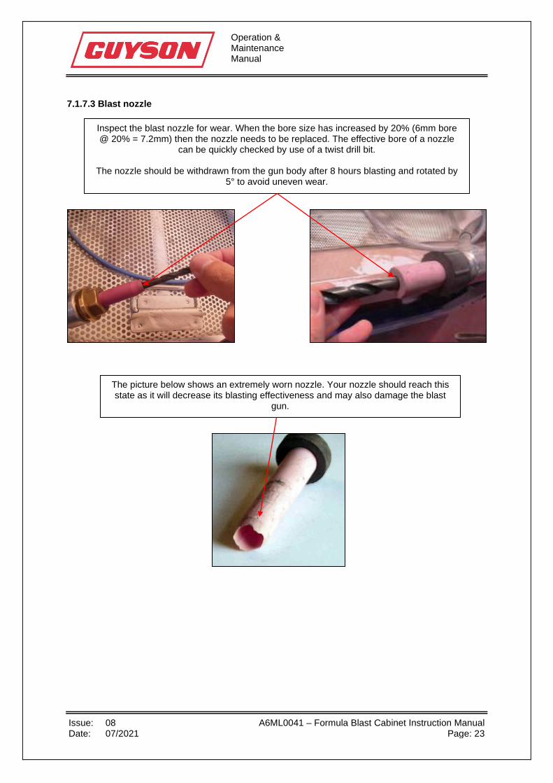
7.1.7.3 Blast nozzle
Inspect the blast nozzle for wear. When the bore size has increased by 20% (6mm bore @ 20% = 7.2mm) then the nozzle needs to be replaced. The effective bore of a nozzle
can be quickly checked by use of a twist drill bit.
The nozzle should be withdrawn from the gun body after 8 hours blasting and rotated by 5° to avoid uneven wear.
The picture below shows an extremely worn nozzle. Your nozzle should reach this state as it will decrease its blasting effectiveness and may also damage the blast
gun.

Operation & Maintenance Manual
Issue: 08 A6ML0041 – Formula Blast Cabinet Instruction Manual Date: 07/2021 Page: 24
7.1.7.4 Airjet
7.1.7.5 Media entry
The media entry should be withdrawn from the gun body and inspected for wear on a regular basis. 7.1.8 Door seals
7.1.9 Topping up media
Top up the media levels as required as media is consumed. This can be roughly gauged from the waste bin on the dust collector. Regular additions of small quantities of media maintain an even particle size and assist in producing consistent results.
If the door gasket strips are worn then:
• this allows noise to escape the cabinet more easily
• media may be able to exit the cabinet
Item Code Description R5SL0024 16mm wide x 5m roll R5SL0027 25mm wide x 5m roll
The airjet should be withdrawn from the gun body after 8 hours blasting to
establish the wear pattern on its outer surface. When wear has become
noticeable, the fitting should be rotated to the next unworn section. When wear
has occurred around the whole circumference, the airjet should be
replaced.
Operation & Maintenance Manual
Issue: 08 A6ML0041 – Formula Blast Cabinet Instruction Manual Date: 07/2021 Page: 25
7.2 Weekly • Inspect gauntlets for wear (see section 7.2.1)
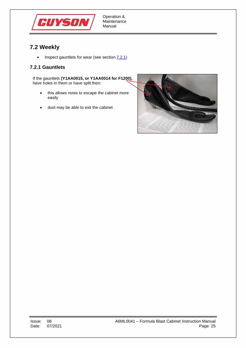
7.2.1 Gauntlets
If the gauntlets (Y1AA0015, or Y1AA0014 for F1200), have holes in them or have split then:
• this allows noise to escape the cabinet more easily
• dust may be able to exit the cabinet
Operation & Maintenance Manual
Issue: 08 A6ML0041 – Formula Blast Cabinet Instruction Manual Date: 07/2021 Page: 26
7.3 Monthly • Drain old media and discard (see section 7.3.1) and refill system with new media (see section
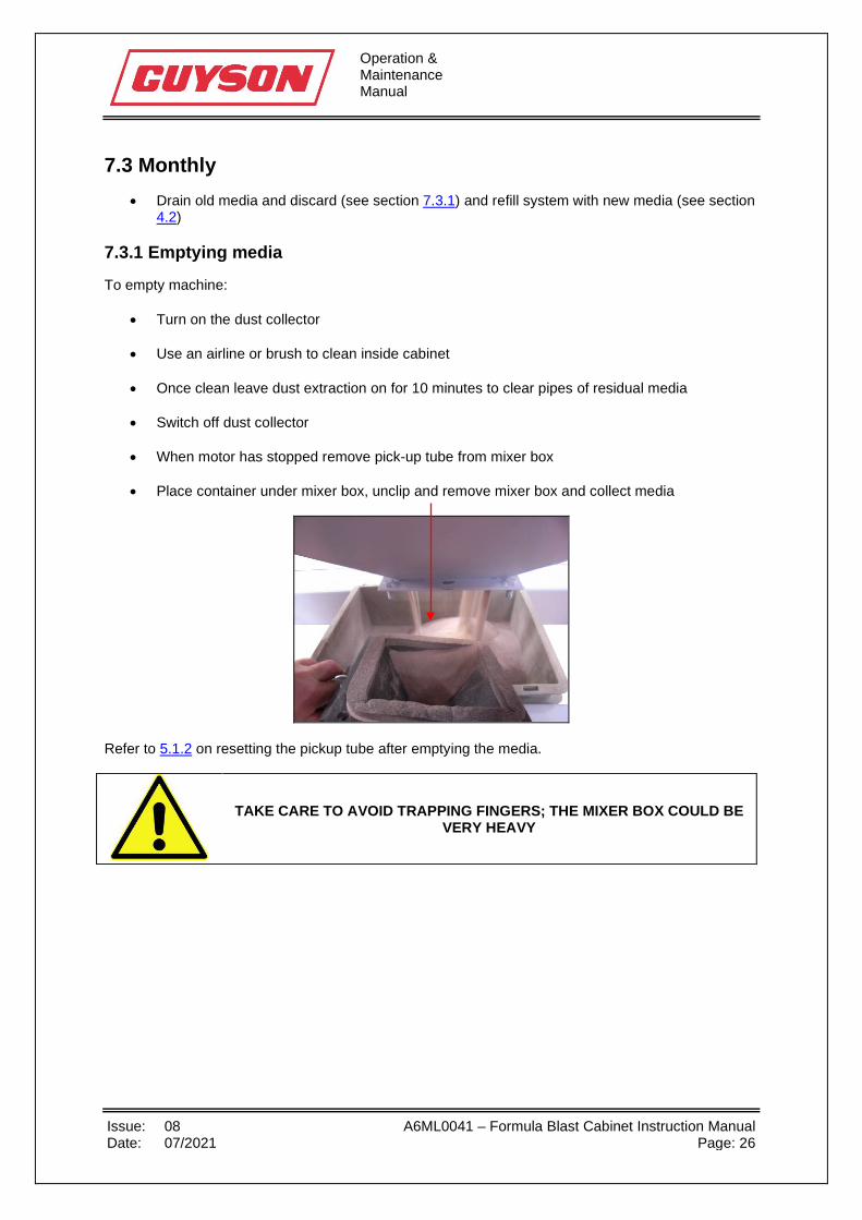
4.2) 7.3.1 Emptying media
To empty machine:
• Turn on the dust collector
• Use an airline or brush to clean inside cabinet
• Once clean leave dust extraction on for 10 minutes to clear pipes of residual media
• Switch off dust collector
• When motor has stopped remove pick-up tube from mixer box
• Place container under mixer box, unclip and remove mixer box and collect media
Refer to 5.1.2 on resetting the pickup tube after emptying the media.
TAKE CARE TO AVOID TRAPPING FINGERS; THE MIXER BOX COULD BE VERY HEAVY
Operation & Maintenance Manual
Issue: 08 A6ML0041 – Formula Blast Cabinet Instruction Manual Date: 07/2021 Page: 27
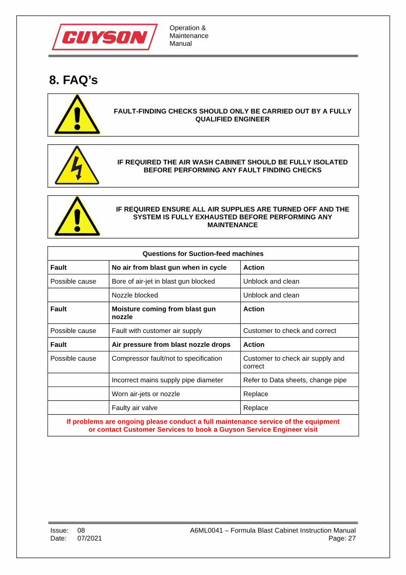
8. FAQ’s
FAULT-FINDING CHECKS SHOULD ONLY BE CARRIED OUT BY A FULLY QUALIFIED ENGINEER
IF REQUIRED THE AIR WASH CABINET SHOULD BE FULLY ISOLATED BEFORE PERFORMING ANY FAULT FINDING CHECKS
IF REQUIRED ENSURE ALL AIR SUPPLIES ARE TURNED OFF AND THE SYSTEM IS FULLY EXHAUSTED BEFORE PERFORMING ANY
MAINTENANCE
Questions for Suction-feed machines
Fault No air from blast gun when in cycle Action
Possible cause Bore of air-jet in blast gun blocked Unblock and clean
Nozzle blocked Unblock and clean
Fault Moisture coming from blast gun nozzle
Action
Possible cause Fault with customer air supply Customer to check and correct
Fault Air pressure from blast nozzle drops Action
Possible cause Compressor fault/not to specification Customer to check air supply and correct
Incorrect mains supply pipe diameter Refer to Data sheets, change pipe
Worn air-jets or nozzle Replace
Faulty air valve Replace
If problems are ongoing please conduct a full maintenance service of the equipment or contact Customer Services to book a Guyson Service Engineer visit

Operation & Maintenance Manual
Issue: 08 A6ML0041 – Formula Blast Cabinet Instruction Manual Date: 07/2021 Page: 28
9. Spares and servicing A maintenance and service agreement for this system is available as an optional extra, for further details please refer to contact details below. When ordering spares or accessories please quote the following information:- Customer Account Number Machine Serial Number Product code of item required If an item has broken that is not listed in the maintenance section and cannot be identified from the assembly drawings in the appendix of this manual then please contact Guyson International on the details below for further help. Customer Service Department Guyson International Ltd Snaygill Industrial Estate Keighley Road Skipton North Yorkshire BD23 2QR Tel: 01756-799911 E-mail: [email protected] Website: www.guyson.co.uk

Operation & Maintenance Manual
Issue: 08 A6ML0041 – Formula Blast Cabinet Instruction Manual Date: 07/2021 Page: 29
9.1 Recommended spares list DESCRIPTION - CABINET 1200 1400 1600 ITEM CODE VIEWING WINDOW - 522 x 180 mm x P2GL0001 VIEWING WINDOW - 625 x 325 mm x x P2GL0008 WINDOW GASKET x x x R5SL0028 ANTIFROSTING SHEET - 524 x 184 mm x P2PF0005 ANTIFROSTING SHEET - 625 X 325 mm x x P2PF0008 FLOOR, FORMULA F1200 x E1AA1675 FLOOR, FORMULA F1400 x E1AA1655 FLOOR, FORMULA F1600 x E1AA1563 AIR HOSE, 10 mm bore x x x R6TB0003 MEDIA HOSE - 10 mm bore x R6TB0014 MEDIA HOSE - 16 mm bore x x R6TB0018 PICK-UP TUBE - 10 mm hose x E1AA3672 PICK-UP TUBE - 16 mm hose x x E1AA4060 MIXER BOX x x x E1AA2452 BULKHEAD LIGHT FITTING BC y y y P3LG0029 BULKHEAD LIGHT FITTING ES y y y P3LG0030 FIXED GAUNTLET - 24” x Y1AA0014 FIXED GAUNTLET - 26” x x Y1AA0015 ARMHOLE BEZEL - ROUND - F1200 x Y1AB0007 ARMHOLE BEZEL - ROUND - F1400/1600 x x Y1AA0028 100 mm DIA HOSE SPINNING x x x Y2AB0013 EXHAUST HOSE 100 mm dia x x x R6TB0030 SIDE DOOR CATCH x x x P2HD0004 BREATHER PAD x x x Y1AB0001 BREATHER PAD BEZEL - ROUND x x x Y1AB0007 COMBINED FILTER/REGULATOR x x x P4AP0050 FOOT PEDAL VALVE x x P4VL0059 PNEUMATIC ISOLATOR ¼“ BSP x x x P4VL0115 DOOR SEAL STRIP 16mm WIDE x 5M ROLL x x x R5SL0024 DOOR SEAL STRIP 25mm WIDE x 5M ROLL x x x R5SL0027 DESCRIPTION – DUST COLLECTOR ITEM CODE FILTER BAG, F21 or F41 D/C Y1CA0000 IMPELLOR – WITH BOSS F21/F41 D/C D2DA0005 MOTOR – 370W – SINGLE PHASE P3MT0000 MOTOR – 370W – THREE PHASE P3MT0001 DESCRIPTION – BLAST GUN PRODUCT CODE GUN BODY, ALUMINIUM 3/8" inlet NOZZLE, CERAMIC 6.4 mm bore D2BA0001 NOZZLE, TUNGSTEN 6.4 mm bore D2BA0004 NOZZLE, CERAMIC 8.0mm bore D2BA0002 NOZLE , TUNGSTEN 8.0mm bore D2BA0005 NOZZLE LOCKNUT D2AA0007 NOZZLE WASHER P1WS0038 NOZZLE GROMMET P2GT0012 AIRJET 2.0 mm bore D1AA0000 AIRJET 2.4 mm bore D1AA0001 AIRJET 2.8 mm bore D1AA0002 AIRJET GASKET P1WS0037 AIRJET COIL SPRING P2SG0000
Operation & Maintenance Manual
Issue: 08 A6ML0041 – Formula Blast Cabinet Instruction Manual Date: 07/2021 Page: 30
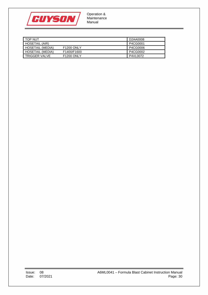
TOP NUT D2AA0008 HOSETAIL (AIR) P4CG0001 HOSETAIL (MEDIA) F1200 ONLY P4CG0006 HOSETAIL (MEDIA) F1400/F1600 P4CG0002 TRIGGER VALVE F1200 ONLY P4VL0072
Operation & Maintenance Manual
Issue: 08 A6ML0041 – Formula Blast Cabinet Instruction Manual Date: 07/2021 Page: 31
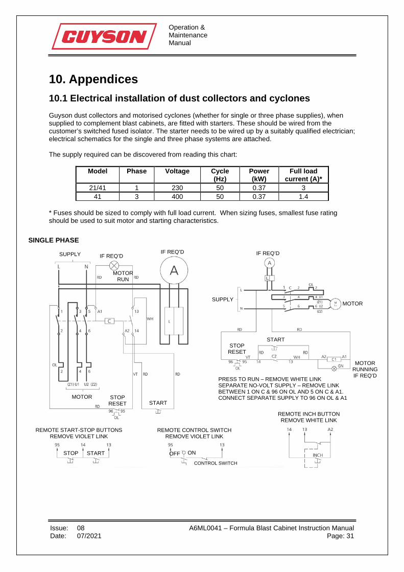
10. Appendices 10.1 Electrical installation of dust collectors and cyclones Guyson dust collectors and motorised cyclones (whether for single or three phase supplies), when supplied to complement blast cabinets, are fitted with starters. These should be wired from the customer’s switched fused isolator. The starter needs to be wired up by a suitably qualified electrician; electrical schematics for the single and three phase systems are attached. The supply required can be discovered from reading this chart:
Model Phase Voltage Cycle (Hz)
Power (kW)
Full load current (A)*
21/41 1 230 50 0.37 3 41 3 400 50 0.37 1.4
* Fuses should be sized to comply with full load current. When sizing fuses, smallest fuse rating should be used to suit motor and starting characteristics.
SUPPLY IF REQ’D
MOTOR RUN
IF REQ’D IF REQ’D
MOTOR SUPPLY
MOTOR RUNNING IF REQ’D
MOTOR STOP RESET
STOP RESET
START
START
PRESS TO RUN – REMOVE WHITE LINK SEPARATE NO-VOLT SUPPLY – REMOVE LINK BETWEEN 1 ON C & 96 ON OL AND 5 ON C & A1. CONNECT SEPARATE SUPPLY TO 96 ON OL & A1
REMOTE INCH BUTTON REMOVE WHITE LINK
REMOTE CONTROL SWITCH REMOVE VIOLET LINK
REMOTE START-STOP BUTTONS REMOVE VIOLET LINK
START STOP ON OFF CONTROL SWITCH
SINGLE PHASE

Operation & Maintenance Manual
Issue: 08 A6ML0041 – Formula Blast Cabinet Instruction Manual Date: 07/2021 Page: 32
If a problem occurs with installation then Guyson International should be contacted to provide support
On both single and three phase motors it is essential to check that the direction of rotation matches the arrow attached to the motor housing. This is best done visually. If the motor is rotating in the wrong direction, it will be necessary to switch off the machine, isolate the electric supply and reverse the position of L1 and L2 on single phase machines or any TWO of the feed wires (L1, L2 or L3) on three phase machines.
3 PHASE
SUPPLY
IF REQ’D
SEPARATE SUPPLY
IF REQ’D
MOTOR SUPPLY
MOTOR RUNNING IF
REQ’D STOP
RESET
STOP RESET
START
START
REMOTE INCH BUTTON REMOVE WHITE LINK REMOTE CONTROL
SWITCH REMOVE VIOLET LINK
REMOTE START-STOP BUTTONS
REMOVE VIOLET LINK
START STOP ON OFF
CONTROL SWITCH
MOTOR
SEPARATE SUPPLY
FOR LINE & NEUTRAL CONTROL, REMOVE LINK BETWEEN A1 & 5 ON C AND WIRE AS SHOWN DOTTED PRESS TO RUN – REMOVE WHITE LINK SEPARATE NO-VOLT SUPPLY – CONNECT AS SHOWN

Operation & Maintenance Manual
Issue: 08 A6ML0041 – Formula Blast Cabinet Instruction Manual Date: 07/2021 Page: 33
If the yellow indicator is visible where the arrow points to, the blue reset button needs to be pressed. If the Dust Collector is still not functional, readjust the trip setting up slightly. If the problem persists, contact Guyson International.