fuzzy-tuned pid anti-swing control of automatic gantry crane 2010
TRANSCRIPT

http://jvc.sagepub.com/Journal of Vibration and Control
http://jvc.sagepub.com/content/16/1/127The online version of this article can be found at:
DOI: 10.1177/1077546309103421
2010 16: 127 originally published online 20 October 2009Journal of Vibration and ControlMahmud Iwan Solihin, Wahyudi and Ari Legowo
Fuzzy-tuned PID Anti-swing Control of Automatic Gantry Crane
Published by:
http://www.sagepublications.com
can be found at:Journal of Vibration and ControlAdditional services and information for
http://jvc.sagepub.com/cgi/alertsEmail Alerts:
http://jvc.sagepub.com/subscriptionsSubscriptions:
http://www.sagepub.com/journalsReprints.navReprints:
http://www.sagepub.com/journalsPermissions.navPermissions:
http://jvc.sagepub.com/content/16/1/127.refs.htmlCitations:
What is This?
- Oct 20, 2009 OnlineFirst Version of Record
- Jan 6, 2010Version of Record >>
at Universiti Sains Malaysia on May 8, 2012jvc.sagepub.comDownloaded from
Fuzzy-tuned PID Anti-swing Control of AutomaticGantry Crane
MAHMUD IWAN SOLIHINWAHYUDIARI LEGOWOIntelligent Mechatronics System Research Unit, Department of Mechatronics Engineering,International Islamic University Malaysia (IIUM), P.O. Box 10, 50728, Kuala Lumpur, Malaysia([email protected])
(Received 7 January 2008� accepted 16 October 2008)
Abstract: Anti-swing control is a well-known term in gantry crane control. It is designed to move the payloadof gantry crane as fast as possible while the payload swing angle should be kept as small as possible at the finalposition. A number of studies have proposed anti-swing control using the well-known proportional, integral,derivative (PID) control method. However, PID controllers cannot always effectively control systems withchanging parameters. Some studies have also proposed intelligent-based control including fuzzy control.However, the designers often have to face the problem of tuning many parameters during the design to obtainoptimum performance. Thus, a lot of effort has to be taken in the design stage. In this paper Fuzzy-tunedPID controller design for anti-swing gantry crane control is presented. The objective is to design a practicalanti-swing control which is simple in the design and also robust. The proposed Fuzzy-tuned PID utilizesfuzzy system as PID gain tuners to achieve robust performance to parameters’ variations in the gantry crane.A complex dynamic analysis of the system is not needed. PID controller is firstly optimized in MATLABusing a rough model dynamic of the system which is identified by conducting a simple open-loop experiment.Then, the PID gains are used to guide the range of the fuzzy outputs of the Fuzzy-tuned PID controllers. Theexperimental results show that the proposed anti-swing controller has satisfactory performance. In addition,the proposed method is straightforward in the design.
Keywords: Anti-swing control, gantry crane, fuzzy-tuned PID.
1. INTRODUCTION
Gantry cranes are widely used in industry for transporting heavy loads and hazardous mate-rials in shipyards, factories, nuclear installations, and high building constructions. The craneshould move the load as fast as possible without causing any excessive movement at the de-sired position. However, most of the common gantry crane results in a swing or sway motionwhen payload is suddenly stopped after a fast motion (Omar, 2003). The swing motion canbe reduced but it will be time-consuming i.e. reducing the productivity. Moreover, the gantrycrane needs a skilful operator to control it manually, based on the operator’s experience, in
Journal of Vibration and Control, 16(1): 127–145, 2010 DOI: 10.1177/1077546309103421
��2010 SAGE Publications Los Angeles, London, New Delhi, Singapore
Figures 2, 5, 6 appear in color online: http://jvc.sagepub.com
at Universiti Sains Malaysia on May 8, 2012jvc.sagepub.comDownloaded from

128 M. I. SOLIHIN ET AL.
order to stop the swing immediately at the accurate position. Furthermore, to unload, theoperator has to prevent the load stops from swaying. Failure to control the crane may alsocause accidents and harm people and surroundings.
Various attempts of anti-swing control for automatic gantry cranes have been proposed.Singhose et al. (1997), Park et al. (2000) and Garrido et al. (2008) adopted input shapingtechnique, which is an open loop approach. However, these methods could not success-fully damp the residual swing angle. Gupta and Bhowal (2004) also presented a simplifiedopen-loop anti-swing technique. They implemented this technique based on velocity controlduring motion. This is an open-loop approach which is sensitive to parameters’ change ofthe system and disturbances. On the other hand, anti-swing feedback controls which are wellknown to be less sensitive to parameter variations and disturbances have also been proposed.
Anti-swing control of gantry or overhead cranes has attracted considerable attention dueto the underactuation property in the payload swing. Sridokbuap et al. (2007) proposed I-PD+PD control for an overhead crane using characteristic ratio assignment (CRA). However,it is natural that PID control is usually not robust to large parameter variations. It is alsoassumed that the dynamic model of the system is known. Chang et al. (2005) combined PIDand Fuzzy compensation to control trolley position and swing motion ofan overhead crane.However, the effect of parameter variations (i.e. payload cable length) was not considered.Matsuo et al. (2004) used PID+Q based controller for anti-swing control. The study focusedon the payload swing suppression, but did not concentrate on error position of the trolley.
Some researches have also applied nonlinear control theory to analyze the properties ofthe crane system (Fang et al., 2003). These approaches are usually too complex for prac-tical use and involve rigorous mathematical analysis. Hua and Shine (2007) proposed thatadaptive coupling control with a nonlinear control scheme incorporating parameter adaptivemechanism be devised to ensure the overall closed-loop system stability.
Furthermore, many researchers have applied fuzzy logic to control overhead cranes be-cause it can mimic human behavior accurately (Renno et al., 2004). Although they do nothave an apparent structure of PID controllers, fuzzy logic controllers may be consideredas nonlinear PID controllers whose parameters can be determined online based on the er-ror signal and its time derivatives. As the nature of a fuzzy control system requires expertknowledge to tune the parameters, which is often difficult and time-consuming, instead theysometimes adopted fuzzy logic and combined with their proposed techniques. Benhidjeband Gissinger (1995) discussed the comparison of a fuzzy logic control system and LinearQuadratic Gaussian control (LQG) for an overhead crane. Wahyudi et al. (2007) proposedfuzzy control combined with a practical control approach. Furthermore, Liu and Zhoa (2005)proposed an adaptive sliding mode control method with fuzzy tuning of slope of sliding sur-face for a 2-dimension overhead crane. In Li et al. (2005), self-adaptive fuzzy PID is pre-sented combined with a feedforward anti-swing scheme for bridge crane control. Only fixedcable length is considered, however. The fuzzy rules are also not concise. In the other work,Trabia et al. (2006) have proposed general anti-swing fuzzy control for crane system. Intheir system, inverse dynamics is still needed. As far as the authors are concerned, there isno general procedure for a robust and practical anti-swing control of gantry crane found inthe literature.
This paper discusses the design of Fuzzy-tuned PID anti-swing control of an automaticgantry crane system. The objective of this work is to design a practical anti-swing controlwhich is simple in the design and also robust. The time-consuming process of system mod-
at Universiti Sains Malaysia on May 8, 2012jvc.sagepub.comDownloaded from
FUZZY-TUNED PID ANTI-SWING CONTROL OF AUTOMATIC GANTRY CRANE 129
eling and analysis should also be eliminated. One of the reasons to use Fuzzy is because itis basically a model independent approach. Only information about error and error rates areused. Thus, it is also possible to develop the proposed control method further for self-tuningfuzzy control. At the end, a robust and practical anti-swing control of gantry crane can beachieved. In practice, only a rough model of the system is needed, which is straightforwardto identify experimentally. The developed dynamic mathematical model here is basicallyused for simulation study.
The proposed Fuzzy-tuned PID control has simple structure of PID control. Instead ofhaving fixed PID gains, the gains are determined directly by means of a Mamdani-fuzzyinference system. Weighting factors are also added to fuzzy output, which is directly relatedto the PID gains, so that the universe of discourse of the fuzzy system can be normalized. Inaddition, this weighting factor can also be tuned further by a self-tuning mechanism in orderto develop a robust and practical anti-swing control using a model independent approach.Indeed, the proposed Fuzzy-PID method here can be classified as fuzzy self-tuning PID or aclass of adaptive fuzzy control (Mudi and Pal, 1999) although the scheme has not been foundbefore in any of the literature.
Experimental study is also conducted to evaluate the effectiveness of the proposedmethod. Previously, a rough model of the system was identified by open-loop experiment.Then, PID controller was optimized using Simulink Response Optimization in MATLABaccording to the identified rough model. Thus, the purpose of PID controller is twofold here.First, it is used as a comparison with the proposed Fuzzy-tuned PID controller. Second, thePID gains are used as a guideline to the fuzzy output in the Fuzzy-tuned PID controllers.The result shows that the proposed Fuzzy-tuned PID anti-swing controllers outperforms thePID anti-swing controller. The proposed controller has the obvious advantage of robustnessto parameters’ variations for anti-swing control.
2. CRANE DYNAMIC
The gantry crane system is an underactuated system where the number of inputs is less thanthe number of outputs. When the input signal is given to the actuator, the trolley starts toaccelerate whilst causing a swing of payload hanging on a flexible cable. Nonlinear dynamicmodel of 2-D gantry crane prototype is derived using Lagrange equations. Notice that a 3-Dgantry crane can be decoupled into its 2-D one. Figure 1 shows the diagram of gantry cranemechanism where m1�m2� l� x� �� B and F are payload mass, trolley mass, cable length,horizontal position of trolley, swing angle, damping friction and driving force respectively.The generalized coordinates are trolley position and swing angle. The equation of motion ofgantry crane system is obtained. See Table 8 for the complete list of symbols.
�m1 � m2� �x �m1l �� cos � � m1l ��2sin � � B �x � F (1)
m1l2 �� � m1l �x cos � � m1gl sin � � 0� (2)
The trolley is driven by a DC motor. The input voltage to the motor is limited by �5 to �5volts. The dynamic of the DC motor circuit is also included.
at Universiti Sains Malaysia on May 8, 2012jvc.sagepub.comDownloaded from

130 M. I. SOLIHIN ET AL.
Figure 1. Trolley crane model.
V � Ri � L�i � Ke ��m (3)
Tm � Kti� (4)
When L is neglected, equation (3) becomes:
V � Ri � Ke ��m� (5)
Applying Newton’s second law of motion to the motor shaft, an equation is obtained as:
Jm ��m � Tm � TL
r� (6)
Since moment inertia of motor, Jm , is very small, then equation (6) can be written as:
Tm � TL
r(7)
with V� R� L � i� Tm� TL� Kt � Ke� �m and r are respectively input voltage, resistance, induc-tance, armature current, motor torque, load torque, torque constant, electric constant, rotorangle position, and gear ratio. In addition, some equations related to rotational horizontalmotions are (rp is radius of pulley):
TL � Frp (8)
�m � r
rpx � (9)
Finally, equations (3–9) are combined with equation (1) resulting in nonlinear mathematicalmodel. It can be written as follows:
at Universiti Sains Malaysia on May 8, 2012jvc.sagepub.comDownloaded from
FUZZY-TUNED PID ANTI-SWING CONTROL OF AUTOMATIC GANTRY CRANE 131
V � A1 �x � B1 �x � C1��� cos � � ��2sin �� (10)
where:
A1 � Ker
rp� B Rrp
KtrC1 � m1l Rrp
KtrB1 � Rrp
Ktr�m1 �m2��
In order to make simpler analysis in linear control theory, the nonlinear model can belinearized by assuming small � during control �sin � � � and cos � � 1). The linearizedmodel of gantry crane dynamic is:
V � A1 �x � B1 �x � C1 �� (11)
l �� � �x � g� � 0� (12)
Equations (11) and (12) show the dynamic of this underactuated system in differential equa-tions. In transfer functions, these can be written into two equations to respectively representinput output transfer as:
X �s�
V �s�� ls2 � g
s��B1l � C1�s3 � A1ls2 � B1gs � A1g�(13)
��s�
V �s�� �s
�B1l � C1�s3 � A1ls2 � B1gs � A1g� (14)
Furthermore, for practicality, if a trolley position is identified experimentally withoutconsidering the swing (l � 0 and payload is attached directly to the cart/trolley), equation(13) is reduced to:
X �s�
V �s�� 1�B1
s �s � A1�B1�� K
s�s � �� (15)
where K and � are unknown constant parameters which will be identified experimentally.The detail of identification procedure is discussed in the next section. While the swing anglemodel is derived from equation (12) in which all parameters (l and g) are known:
��s�
X �s�� �s2
ls2 � g� (16)
Finally, the rough model of the gantry crane system with one input and two outputs is ob-tained by equations (15) and (17) as:
��s�
V �s�� K
s�s � ���s2
�ls2 � g�� (17)
at Universiti Sains Malaysia on May 8, 2012jvc.sagepub.comDownloaded from

132 M. I. SOLIHIN ET AL.
Figure 2. Lab-scale gantry crane prototype.
Figure 3. Assumed speed response of trolley crane to a step input.
3. IDENTIFICATION OF UNKNOWN PARAMETERS
To identify the parameters of K and � , the open loop speed responses of the trolley position(for maximum and minimum payload mass) to step input are recorded. The lab scale gantrycrane prototype is shown in Figure 2. In this study, parameter identification is done experi-mentally following this explanation. The trolley’s speed response (Vcart ) to a unit step inputis as shown in Figure 3 and is written as:
Vcart�s� � K
s � �1
s(18)
Vcart�t� � K �1� e� t�� (19)
at Universiti Sains Malaysia on May 8, 2012jvc.sagepub.comDownloaded from

FUZZY-TUNED PID ANTI-SWING CONTROL OF AUTOMATIC GANTRY CRANE 133
Figure 4. Simplified diagram of anti-swing control.
Table 1. Identified parameter.
K �
2.66 11.1
From the response above, K can be measured as steady state speed. Then, the followingequations can be derived to solve for unknown constant � :
0�1K � K �1� e�� t1� (20)
0�9K � K �1� e�� t2� (21)
� � 2�2
t2 � t1� (22)
By conducting open-loop experiment to record trolley speed response, the unknown pa-rameters are found for payload mass of 2.5 kg. The values are listed in Table 1.
4. PID ANTI-SWING CONTROL
The main purpose of anti-swing control is to transfer the load as fast as possible withoutcausing any excessive swing at the end position. The automatic gantry crane proposed by theresearchers commonly uses two sets of controllers to control both trolley position and swingangle of the payload as shown in Figure 4. PID controller is used for trolley positioningcontrol and PD is used for swing control. The close loop transfer functions can be calculated.The overall close loop characteristic polynomial is found as:
Kcl � s5 � a4s4 � a3s3 � a2s2 � a1s � a0 (23)
where:
at Universiti Sains Malaysia on May 8, 2012jvc.sagepub.comDownloaded from
134 M. I. SOLIHIN ET AL.
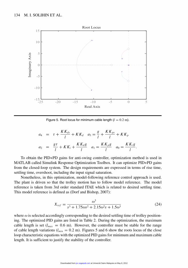
Figure 5. Root locus for minimum cable length (l � 0�2 m).
a4 � � � K Kds
l� K Kd a3 � g
l� K K ps
l� K K p
a2 � g�
l� K Ki � K Kd g
la1 � K K pg
la0 � K Ki g
l�
To obtain the PID+PD gains for anti-swing controller, optimization method is used inMATLAB called Simulink Response Optimization Toolbox. It can optimize PID+PD gainsfrom the closed-loop system. The design requirements are expressed in terms of rise time,settling time, overshoot, including the input signal saturation.
Nonetheless, in this optimization, model-following reference control approach is used.The plant is driven so that the trolley motion has to follow model reference. The modelreference is taken from 3rd order standard ITAE which is related to desired settling time.This model reference is defined as (Dorf and Bishop, 2007):
Xref � �3
s3 � 1�75�s2 � 2�15�2s � 1�5�3(24)
where � is selected accordingly corresponding to the desired settling time of trolley position-ing. The optimized PID gains are listed in Table 2. During the optimization, the maximumcable length is set (lmax � 0�6 m). However, the controller must be stable for the rangeof cable length variations (lmin � 0�2 m). Figures 5 and 6 show the roots locus of the closeloop characteristic equations with the optimized PID gains for minimum and maximum cablelength. It is sufficient to justify the stability of the controller.
at Universiti Sains Malaysia on May 8, 2012jvc.sagepub.comDownloaded from

FUZZY-TUNED PID ANTI-SWING CONTROL OF AUTOMATIC GANTRY CRANE 135
Figure 6. Root locus for maximum cable length (l � 0�6 m).
Table 2. Optimized PID gains.
K p Ki Kd K ps Kds
2.0 0.7 4.1 16.1 0.2
5. FUZZY-TUNED PID CONTROL DESIGN
The Fuzzy-tuned PID control is then designed. To control the position of the trolley crane,Fuzzy-tuned PID is proposed, whereas anti-swing control is performed by Fuzzy-tuned PDcontrol. The PID gains obtained above are used as a guideline for fuzzy output of the pro-posed Fuzzy-tuned PID controllers. The controller structure is shown in Figure 7.
Initially, Mamdani fuzzy inference system is designed as fuzzy tuner. It has error anderror rate as inputs and the tuned gain as the output. The fuzzy membership for the output issingleton membership function. The fuzzy system for the input has five Gaussian member-ship functions distributed equivalently over the determined range (universe of discourse).
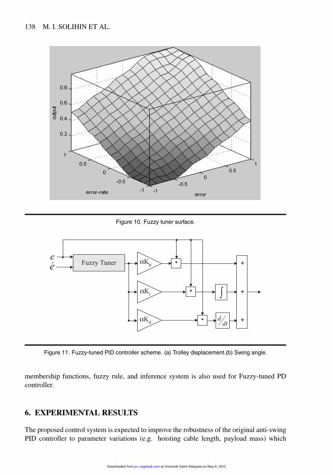
The range of each fuzzy membership is normalized in order to have simple structure offuzzy system. The range is set up to from –1 to 1 for fuzzy input and from 0 to 1 for fuzzyoutput. The fuzzy membership functions for error and error rate are as shown in Figure 8.Figure 9 shows the fuzzy membership functions for fuzzy tuner output. Here, NB, NS, Z,PS and PB are assigned to negative big, negative small, zero, positive small and positive bigrespectively in the fuzzy rule. The if-then fuzzy rules are simply based on Macvicar-WhelanMatrix (Visioli and Finzi, 1998). This is shown in Table 3. Then, the fuzzy tuner surface canbe seen in Figure 10, which is flat near the extremes of the range.
at Universiti Sains Malaysia on May 8, 2012jvc.sagepub.comDownloaded from

136 M. I. SOLIHIN ET AL.
Figure 7. Fuzzy-tuned PID control scheme for anti-swing control.
Table 3. If-then rule for fuzzy tuner.
ERROR RATENB NS Z PS PB
NB Z Z VS SM MNS Z VS SM M BM
ERROR Z VS SM M BM VBPS SM M BM VB BPS M BM VB B B
The performance of the controller is determined by adding weighting factors on normal-ized fuzzy output. These weighting/scaling factors are proportional respectively to K p, Ki ,Kd , K ps and Kds which are the proportional, integral and derivative gains for position controland proportional, derivative gains for anti-swing control. The weighting or scaling factors onfuzzy tuner output are selected as Kx , where x is index for each PID gains. In this paper, as a multiplier to the PID gains shown in Table 2. The value of is 1.25 obtained bytrial as a compromise. In future work, different values of scaling factor may be proposed forpositioning and swing controller. This value can be tuned on-the-fly over the variation of 1to 2 using self-tuning mechanism providing only information about error and error rate.
Therefore, the purpose of PID controller is twofold. First, it is used as comparison withthe proposed Fuzzy-tuned PID controller here. Second, the PID gains are used as a guidelinefor weighting factors in the output of the proposed Fuzzy-tuned PID controllers to improvethe robustness of the original PID controller.
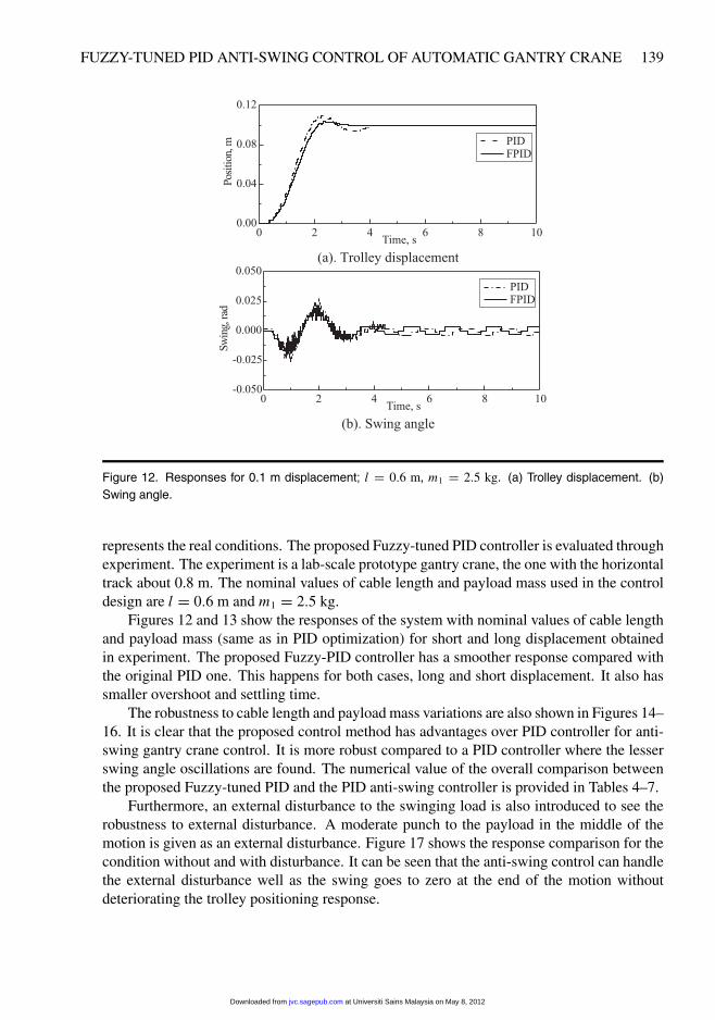
The proposed Fuzzy-tuned PID controller scheme can be seen in Figure 11. This schemeis also applicable for Fuzzy-tuned PD controller with the corresponding weighting factors ofK ps and Kds respectively. For simplicity, the same structure of fuzzy tuner in terms of
at Universiti Sains Malaysia on May 8, 2012jvc.sagepub.comDownloaded from

FUZZY-TUNED PID ANTI-SWING CONTROL OF AUTOMATIC GANTRY CRANE 137
Figure 8. Fuzzy Gaussian membership functions for input.
Figure 9. Fuzzy singleton membership functions for output.
at Universiti Sains Malaysia on May 8, 2012jvc.sagepub.comDownloaded from
138 M. I. SOLIHIN ET AL.
Figure 10. Fuzzy tuner surface.
Figure 11. Fuzzy-tuned PID controller scheme. (a) Trolley displacement.(b) Swing angle.
membership functions, fuzzy rule, and inference system is also used for Fuzzy-tuned PDcontroller.
6. EXPERIMENTAL RESULTS
The proposed control system is expected to improve the robustness of the original anti-swingPID controller to parameter variations (e.g. hoisting cable length, payload mass) which
at Universiti Sains Malaysia on May 8, 2012jvc.sagepub.comDownloaded from
FUZZY-TUNED PID ANTI-SWING CONTROL OF AUTOMATIC GANTRY CRANE 139
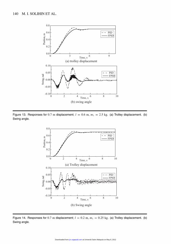
Figure 12. Responses for 0.1 m displacement� l � 0�6 m, m1 � 2�5 kg. (a) Trolley displacement. (b)Swing angle.
represents the real conditions. The proposed Fuzzy-tuned PID controller is evaluated throughexperiment. The experiment is a lab-scale prototype gantry crane, the one with the horizontaltrack about 0.8 m. The nominal values of cable length and payload mass used in the controldesign are l � 0�6 m and m1 � 2�5 kg.
Figures 12 and 13 show the responses of the system with nominal values of cable lengthand payload mass (same as in PID optimization) for short and long displacement obtainedin experiment. The proposed Fuzzy-PID controller has a smoother response compared withthe original PID one. This happens for both cases, long and short displacement. It also hassmaller overshoot and settling time.
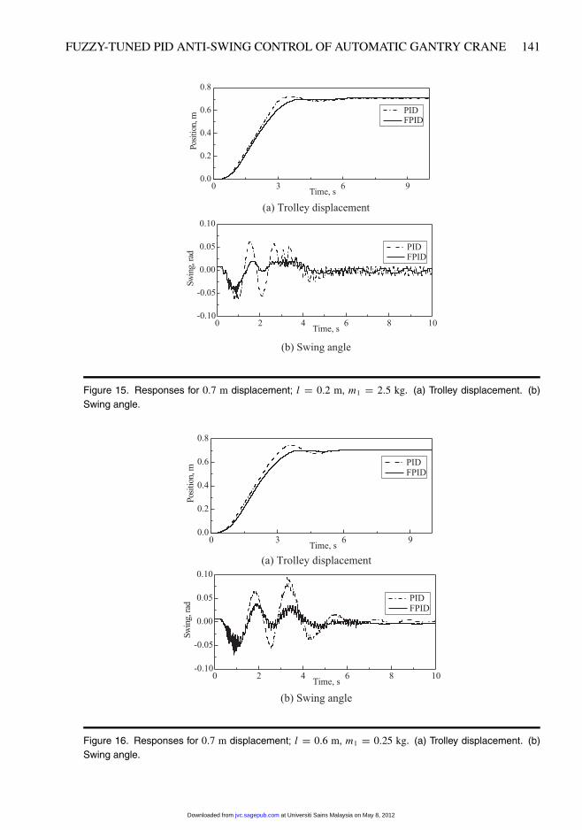
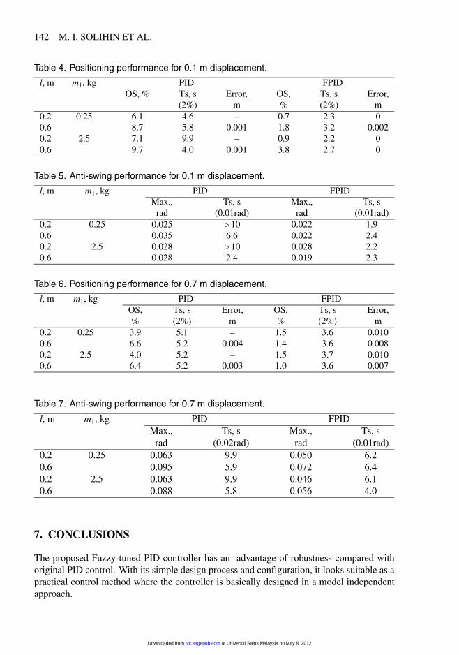
The robustness to cable length and payload mass variations are also shown in Figures 14–16. It is clear that the proposed control method has advantages over PID controller for anti-swing gantry crane control. It is more robust compared to a PID controller where the lesserswing angle oscillations are found. The numerical value of the overall comparison betweenthe proposed Fuzzy-tuned PID and the PID anti-swing controller is provided in Tables 4–7.
Furthermore, an external disturbance to the swinging load is also introduced to see therobustness to external disturbance. A moderate punch to the payload in the middle of themotion is given as an external disturbance. Figure 17 shows the response comparison for thecondition without and with disturbance. It can be seen that the anti-swing control can handlethe external disturbance well as the swing goes to zero at the end of the motion withoutdeteriorating the trolley positioning response.
at Universiti Sains Malaysia on May 8, 2012jvc.sagepub.comDownloaded from
140 M. I. SOLIHIN ET AL.
Figure 13. Responses for 0�7 m displacement� l � 0�6 m, m1 � 2�5 kg. (a) Trolley displacement. (b)Swing angle.
Figure 14. Responses for 0�7 m displacement� l � 0�2 m, m1 � 0�25 kg. (a) Trolley displacement. (b)Swing angle.
at Universiti Sains Malaysia on May 8, 2012jvc.sagepub.comDownloaded from
FUZZY-TUNED PID ANTI-SWING CONTROL OF AUTOMATIC GANTRY CRANE 141
Figure 15. Responses for 0�7 m displacement� l � 0�2 m, m1 � 2�5 kg. (a) Trolley displacement. (b)Swing angle.
Figure 16. Responses for 0�7 m displacement� l � 0�6 m, m1 � 0�25 kg. (a) Trolley displacement. (b)Swing angle.
at Universiti Sains Malaysia on May 8, 2012jvc.sagepub.comDownloaded from
142 M. I. SOLIHIN ET AL.
Table 4. Positioning performance for 0.1 m displacement.
l, m m1, kg PID FPIDOS, % Ts, s Error, OS, Ts, s Error,
(2%) m % (2%) m0.2 0.25 6.1 4.6 – 0.7 2.3 00.6 8.7 5.8 0.001 1.8 3.2 0.0020.2 2.5 7.1 9.9 – 0.9 2.2 00.6 9.7 4.0 0.001 3.8 2.7 0
Table 5. Anti-swing performance for 0.1 m displacement.
l, m m1, kg PID FPIDMax., Ts, s Max., Ts, s
rad (0.01rad) rad (0.01rad)0.2 0.25 0.025 10 0.022 1.90.6 0.035 6.6 0.022 2.40.2 2.5 0.028 10 0.028 2.20.6 0.028 2.4 0.019 2.3
Table 6. Positioning performance for 0.7 m displacement.
l, m m1, kg PID FPIDOS, Ts, s Error, OS, Ts, s Error,% (2%) m % (2%) m
0.2 0.25 3.9 5.1 – 1.5 3.6 0.0100.6 6.6 5.2 0.004 1.4 3.6 0.0080.2 2.5 4.0 5.2 – 1.5 3.7 0.0100.6 6.4 5.2 0.003 1.0 3.6 0.007
Table 7. Anti-swing performance for 0.7 m displacement.
l, m m1, kg PID FPIDMax., Ts, s Max., Ts, s
rad (0.02rad) rad (0.01rad)0.2 0.25 0.063 9.9 0.050 6.20.6 0.095 5.9 0.072 6.40.2 2.5 0.063 9.9 0.046 6.10.6 0.088 5.8 0.056 4.0
7. CONCLUSIONS
The proposed Fuzzy-tuned PID controller has an advantage of robustness compared withoriginal PID control. With its simple design process and configuration, it looks suitable as apractical control method where the controller is basically designed in a model independentapproach.
at Universiti Sains Malaysia on May 8, 2012jvc.sagepub.comDownloaded from

FUZZY-TUNED PID ANTI-SWING CONTROL OF AUTOMATIC GANTRY CRANE 143
Figure 17. Responses with and without disturbance (l � 0�6 m, m1 � 1�0 kg).
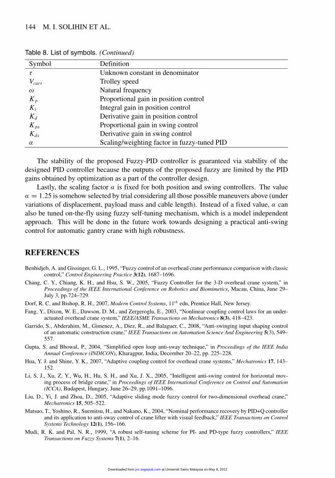
Table 8. List of symbols.
Symbol Definitionm1 Payload massm2 Trolley massl Cable lengthx Horizontal position of trolley� Swing angleB Damping frictionF Driving forceV Input voltageR Resistance of DC motorL Inductance of DC motori Armature currentTm Motor torqueTL Load torqueKt Torque constantKe Electric constant�m Rotor angle positionr Gear ratiorp Radius of pulleyK Unknown constant in numerator
at Universiti Sains Malaysia on May 8, 2012jvc.sagepub.comDownloaded from
144 M. I. SOLIHIN ET AL.
Table 8. List of symbols. (Continued)
Symbol Definition� Unknown constant in denominatorVcart Trolley speed� Natural frequencyK p Proportional gain in position controlKi Integral gain in position controlKd Derivative gain in position controlK ps Proportional gain in swing controlKds Derivative gain in swing control Scaling/weighting factor in fuzzy-tuned PID
The stability of the proposed Fuzzy-PID controller is guaranteed via stability of thedesigned PID controller because the outputs of the proposed fuzzy are limited by the PIDgains obtained by optimization as a part of the controller design.
Lastly, the scaling factor is fixed for both position and swing controllers. The value � 1�25 is somehow selected by trial considering all those possible maneuvers above (undervariations of displacement, payload mass and cable length). Instead of a fixed value, canalso be tuned on-the-fly using fuzzy self-tuning mechanism, which is a model independentapproach. This will be done in the future work towards designing a practical anti-swingcontrol for automatic gantry crane with high robustness.
REFERENCES
Benhidjeb, A. and Gissinger, G. L., 1995, “Fuzzy control of an overhead crane performance comparison with classiccontrol,” Control Engineering Practice 3(12), 1687–1696.
Chang, C. Y., Chiang, K. H., and Hsu, S. W., 2005, “Fuzzy Controller for the 3-D overhead crane system,” inProceedings of the IEEE International Conference on Robotics and Biomimetics, Macau, China, June 29–July 3, pp.724–729.
Dorf, R. C. and Bishop, R. H., 2007, Modern Control Systems, 11th edn, Prentice Hall, New Jersey.Fang, Y., Dixon, W. E., Dawson, D. M., and Zergeroglu, E., 2003, “Nonlinear coupling control laws for an under-
actuated overhead crane system,” IEEE/ASME Transactions on Mechatronics 8(3), 418–423.Garrido, S., Abderahim, M., Gimenez, A., Diez, R., and Balaguer, C., 2008, “Anti-swinging input shaping control
of an automatic construction crane,” IEEE Transactions on Automation Science And Engineering 5(3), 549–557.
Gupta, S. and Bhowal, P., 2004, “Simplified open loop anti-sway technique,” in Proceedings of the IEEE IndiaAnnual Conference (INDICON), Kharagpur, India, December 20–22, pp. 225–228.
Hua, Y. J. and Shine, Y. K., 2007, “Adaptive coupling control for overhead crane systems,” Mechatronics 17, 143–152.
Li, S. J., Xu, Z. Y., Wu, H., Hu, S. H., and Xu, J. X., 2005, “Intelligent anti-swing control for horizontal mov-ing process of bridge crane,” in Proceedings of IEEE International Conference on Control and Automation(ICCA), Budapest, Hungary, June 26–29, pp.1091–1096.
Liu, D., Yi, J. and Zhoa, D., 2005, “Adaptive sliding mode fuzzy control for two-dimensional overhead crane,”Mechatronics 15, 505–522.
Matsuo, T., Yoshino, R., Suemitsu, H., and Nakano, K., 2004, “Nominal performance recovery by PID+Q controllerand its application to anti-sway control of crane lifter with visual feedback,” IEEE Transactions on ControlSystems Technology 12(1), 156–166.
Mudi, R. K. and Pal, N. R., 1999, “A robust self-tuning scheme for PI- and PD-type fuzzy controllers,” IEEETransactions on Fuzzy Systems 7(1), 2–16.
at Universiti Sains Malaysia on May 8, 2012jvc.sagepub.comDownloaded from
FUZZY-TUNED PID ANTI-SWING CONTROL OF AUTOMATIC GANTRY CRANE 145
Omar, H. M., 2003, Control of Gantry and Tower Cranes, PhD Dissertation, Virginia Polytechnic Institute and StateUniversity, Blacksburg, Virginia.
Park, B. J., Hong, K. S., and Huh, C. D., 2000, “Time-efficient input shaping control of container crane systems,in Proceedings of IEEE International Conference on Control Application, Anchorage, AK, September, pp.80–85.
Renno, J. M., Trabia, M. B., and Moustafa, K. A. F., 2004, “Anti-swing adaptive fuzzy controller for an overheadcrane with hoisting,” in Proceedings of IMECE ASME International Mechanical Engineering Congress &Exposition, Anheim, CA, November 14–19.
Singhose, W. E., Porter, L. J., and Seering, W. P., 1997, “Input shaped control of a planar gantry crane with hoisting,”in Proceedings of the American Control Conference, Albuquerque, NM, June 4–6, pp. 97–100.
Sridokbuap, W., Nundrakwang, S., Benjanarasuth, T., Ngamwiwit, J., and Komine, N., 2007, “I-PD and PD con-trollers designed by CRA method for overhead crane system,” in Proceedings of the International Confer-ence on Control, Automation and Systems (ICAAS), Seoul, Korea, October 17–20, pp. 326–330.
Trabia, M. B., Renno, J. M., and Moustafa, K. A. F., 2006, “A general anti-swing fuzzy controller for an overheadcrane with hoisting,” in Proceedings of the IEEE International Conference on Fuzzy Systems, Vancouver,Canada, July 16–21.
Visioli, A. and Finzi, G., 1998, “PID tuning with fuzzy set-point weighting,” in Proceedings of the IEEE Interna-tional Conferences on Control Applications Vol. 1, pp. 638–642.
Wahyudi, Jalani, J., Muhida, R., and Salami, M. J. E., 2007, “Control strategy for automatic gantry crane systems:a practical and intelligent approach,” International Journal of Advanced Robotic Systems 4, 447–456.
at Universiti Sains Malaysia on May 8, 2012jvc.sagepub.comDownloaded from