generation of ramp pattern using modified differential .... 9 issue 6/version-3... · abstract:...
TRANSCRIPT

IOSR Journal of Electronics and Communication Engineering (IOSR-JECE)
e-ISSN: 2278-2834,p- ISSN: 2278-8735.Volume 9, Issue 6, Ver. III (Nov - Dec. 2014), PP 01-12 www.iosrjournals.org
www.iosrjournals.org 1 | Page
Generation of Ramp Pattern using Modified Differential
Evolution algorithm
T. Vidhya Vathi1, G.S.N. Raju
2
1Research scholar, Dept. of Electronics & Communication Engineering, college of Engineering (A), Andhra
University, Visakhapatnam, Andhrapradesh, India. 2Professor, Dept. of Electronics & Communication Engineering, college of Engineering (A), Andhra University,
Visakhapatnam, Andhrapradesh, India.
Abstract: This paper presents a new pattern synthesis for linear arrays using modified differential evolution
based on harmony search algorithm as an optimization technique. The main objective is to obtain suitable
current excitation amplitude and phase distribution for the linear array antenna elements so that it can produce
the desired ramp shaped beam radiation pattern. There are many optimization techniques available for beam
shaping but a new algorithm can efficiently control both the main lobe shaping and the number of sidelobes
which are present in radiation pattern. The modified differential evolution (MDE) strategy has been developed
by adding three control parameter settings into the classical DE. For this purpose a new mutation and
crossover strategies are considered. The synthesis of desired ramp shaped beam pattern results have been
shown that MDE converges as faster and requires less computation than the other methods.
Index terms:Antenna Arrays, Pattern Synthesis, Control Parameters, Modified Differential Evolution
Algorithm, Beam-Former, and Ramp Shaped-Beam Patterns.
I. Introduction: In modern wireless communication systems, antenna arrays play an important role in detecting and
processing signals arriving from different directions. Array pattern synthesis is required in different
applicationslike phased array radar cellular and mobile communication, satellite, radar and military systems for
the improvement of signal quality [1].
In recent technology, the need of antenna arrays with shaped beam patterns are increased day by day
for the purpose of improvement of communication in which specific beam shape is required for scan and non scan application [2]. In this present work, the objective is to generate a ramp shaped beam radiation pattern from
the antenna array pattern synthesis.
This problem consists of finding weights [3] that satisfy a set of specifications and also used to
determine the physical layout of the array to produce a desired shaped beam radiation pattern [4].To obtain this,
a set of amplitude excitation coefficients and excitation phases that closely produce desired beam shapes are
required. These are carried out by the equally spaced and unequally spaced linear aperiodic arrays. The shape of
the desired radiation pattern can vary depending on the application. Ramp shaped beams does not exhibit
symmetry about the bore sight direction like pencil beams [5]. These are useful in point to point communication
beam shaping pattern can be achieved through amplitude tapering, phase tapering or space tapering or any of the
combination of these two.The main aim of this work is to generate a ramp shaped radiation pattern from the
antenna arrays using Modified Differential Evolution based on Harmony Search Algorithm. Many of the antenna array pattern synthesis techniques can be found in the literature for the generation
of shaped beam radiation patterns [6]-[7]. G. S. N. Raju, A. Sudhakar et al., [8]-[9] has been showed that
generation of optimized ramp type of radiation patterns from an antenna array pattern synthesis. In the above
synthesis procedures, both the amplitude and phase of each array element are optimized. G. S. N. Raju, A.
Sudhakar et al., [10]-[11] developed and reported the realization for the generation of ramp and stair – step
patterns using amplitude control and phase-only control techniques. To avoid the complexity involved in
conventional analytical synthesis methods [12].
In recent years, population based stochastic methods such as evolutionary algorithm [13], Genetic
algorithm (GA) [14], Simulated annealing (SA) [15] Cannonical PSO, some PSO variants has been used for the
design of linear array. An adaptive Boolean PSO [15] is developed by Zaharis and Yioultsis for beam-forming
on linear antenna array. Liu et al., in [16] suggested a new method for the synthesis of linear array with shaped
power pattern. Guney and Basnug [17] used Bacterial Foraging Algorithm (BFA) for interference suppression of linear array. Some other G.K. Mahantietal., antenna array design uses firefly and artificial Bees colony
algorithm [18].
Recently the most prominent and efficient differential evolution algorithm [19] has been applied for
the design of beam shaping antenna array pattern synthesis [20].It is vary superior than the other methods

Generation of Ramp Pattern using Modified differential evolution algorithm
www.iosrjournals.org 2 | Page
interns of convergence speed androbustness.Different improved variants of original classic DE have been
suggested that yields a better result in different situations [21]-[23].In thispaper, a modified differential
evolution strategy based on harmony search algorithm [24] is used an optimization technique.This method uses
three trail vector generation strategies and three control parameter settings.There are usually three evolutionary
operations in classic DE, which are summed up to two operations in the Modified DE. These modifications help
to overcome some drawbacks of classic DE.A new mutation and crossover strategies are considered in this
proposed algorithm.
The rest of this paper is organized asfollows: SectionII briefly introduces Modified Differential
Evolution Algorithm;SectionIII describes the mathematical formulation and the related work on MDE. The
numerical simulation results are reported in Section IV, and finally the conclusion is given in Section V.
II. Modified Differential Evolution Algorithm: 1. Initialization
Classic DEstarts with a new population of NP, D-dimensional vectorsXi,G = [1,2,…………NP] where
the index ‗i‘ denotes the population and ‗G‘ denotes the generation to which the population belongs. It involves
two stages,namely, initialization and evolution.Initialization generates initial population P0 then the population
evolves from one generation (Pn) to the next (Pn+1) generation until the termination conditions are met. While
evolving from one generation (Pn) to next (Pn+1) generation DE depends on three main operators
namely,mutation, crossover and selection that are executed in sequence.There are three evolutionary operations
in classic DE which are summed up to two operators in the modified differential evolution algorithm [MDE].
2. Differential Mutation and Crossover:
For each individual Xi,Gin the population, a mutant vector Vi,G is produced according to the following
formula.
(1)
Where the indexes r1, r2, r2ϵ {1, 2, 3 ….NP} are randomly selected such r1≠ r2 ≠ r2 ≠ i.
The element of mutant vector Vi,G+1 is generated by the differential mutation, whenever a randomly
generated number between [0, 1] is less than or equal to the CR value otherwise, it is equal to the corresponding
element of the individual Vi,G+1.F is a real and constant factors ϵ [0, 2] which controls the amplification of the
differential variation (Xr2,G-Xr3,G). Different values of ‗y‘ could lead to differential mutation strategies such as
DE /rand/1/bin and DE/best/2/bin.
3. Selection:
The population for the next generation is selected from the individual in current population and its
corresponding trail vector according to the following rule.
(2)
Where f (.) is the objective function to be minimized.It is to say that if the new vector Xi,Gproduced by
differential mutation and crossover operations yields a lower value of the objective function, it would replace
the corresponding individualXi,G in the next generation.
In the modified differential evolution strategy, a new parameter HR is introduced. The element of
mutant vector Vi,Gis generated randomly in the range between [0, 1] is greater than the specified constant
HR.Otherwise, the element is produced by the classic DE. In this case, the probability that each element of mutant vectorVi,G is produced in three ways are followed by the schematic structure as shown in the figure
1.The new way to produce mutant elements introduces the random noise in to the population and improves its
diversity.At the beginning of the generation, minimum CR and maximum F are good to search more space, while
maximum CR and minimum F are good to search accurately and escape the local optimum in the final
generations.

Generation of Ramp Pattern using Modified differential evolution algorithm
www.iosrjournals.org 3 | Page
Figure 1: Probability of the new element generated using harmony search differential evolution
As similar to the harmony search, the changes of two importantparameter CR &F are improved as
follows.
(3) Where CRmin,CRmax are the minimum and maximum adjusting rate of CR and Fmin,Fmax are the minimum and maximum values of F respectively.
To show the excellence performance of Modified Differential Evolution Algorithm the specifications
have been selected from the parameter values of harmony search. These rules are governed by some parameters,
i.e., a scaling weighted factor ‗F‘ and a probability CR, which control the crossover operator. For this purpose
the design specifications for the proposed algorithm have been selected from the control parameter values are
HR=0.9, CRmax=0.95, CRmin=0.2, Fmax=0.6, Fmin=0.1 and Gmax=10,000.
III. Mathematical Formulation 1. Array Methodology:
A linear array is an arrangement of antenna elements placed along a straight line with the orientation of
each element in same direction. The elements are spaced at a distance of λ/2 in order to avoid mutual coupling
and grating lobes. The geometry of ‗N‘ isotropic elements with equal inter-element spacing‗d‘ placed in Z-
direction as shown in figure 2.
The array factor in the azimuth plane is given as
(4) Xn is the position of the nth element which is useful for both odd and even number of elements in the array and is
given in equation form.
Figure 2: schematic diagram for linear array geometry

Generation of Ramp Pattern using Modified differential evolution algorithm
www.iosrjournals.org 4 | Page
Where A(xn) and ϕ(xn) are the amplitude and phase distributions of nth element.
Xn = 2n−N−1
N (5)
‗k‘ is the wave number = 2π/λ
‗λ‘ is the operated wave length
‗L‘ is the length of the array
u1 = u-u0
u = sinθ
u0 = sinθ0
θ0 is the scan angle
2. Objective Function: The goal of the optimization is to generate desired ramp pattern of a specified width (u0) with
acceptable sidelobe level by employing non uniform excitations to individual elements of the antenna array. The
normalized amplitudes in the search range [0, 1] and progressive phase shift values are in between –π to π are
taken as the optimization parameters. Therefore, the fitness function is given as
f = min (w1e1+w2e2) (6)
Where w1 and w2 are the controlled weights and sum of the weights should be one that is represented as
(7) Where ‗e1‘ is the mean square error of the main beam region
(8) Here ‗p‘ represents the number of sampling points in mainlobe region and E1(ui) is the error in main beam
region and it is calculated as
E1 (u) = {E (u) – F (u); 0 ≤ u ≤ u0} (9)
Where F (u) is desired ramp pattern and E (u) is pattern obtained in the evolutionary process. Therefore the desired ramp pattern is represented by
(10) e2 is the least mean square error in the sidelobe region
(11) Where ‗Q‘ is the number of azimuth angles in the sidelobe region and E2 (u) is the error obtained in sidelobe
region and it is calculated as
E2 (u) = {E (u) – F (u); u < 0 & u > u0} (12)
Where E (u) is the pattern obtained in the evolutionary process and F (u) is desired ramp pattern.
IV. Numerical Simulation Results In order to validate the effectiveness of MDE(HSDEA) for non-convex problems, we first considered a
linear array of different elements that are spaced λ/2 distance apart. For the optimized ramp shaped pattern, the
normalized amplitude coefficients and the static phase shifts of the array elements are taken as the optimizing parameters of the MDE algorithm. As can be seen, the average convergence rate for each of the optimized
radiation patterns. It should be pointed out that although the same optimality criterion is adopted in the
subsection, the specific forms of the fitness functions are different, thus leading to different convergence
accuracy.
It is clearly seen that the required number of fitness evaluations varied from 1000 to 60,000 for
different cases which takes only about a minute to hours. Figure 3 presented the performance of the behavior of
cost function versus the number of iterations. In this paper the resultant optimized ramp patterns are observed
for different finite widths (u0) of 0.2, 0.4 and 0.6 by varying the number of elements. Both the amplitude and
phase excitation coefficient weights of each element is optimized to generate the desired radiation pattern.
Radiation patterns are briefly discussed in the following different cases.

Generation of Ramp Pattern using Modified differential evolution algorithm
www.iosrjournals.org 5 | Page
Figure 3: Behavior of fitness function versus number of generations
Case-1: Ramp patterns aregenerated at finite width (u0) 0.2 for different elements.Figure 4 shows the radiation
patternfor 60 elements and its corresponding amplitude, phase distributions are presented in figure 5, figure
6.Radiation pattern obtained for 100 elements is reported in figure 7 its corresponding amplitude distribution
and phase distribution for 100 elements are presented in figure 8 and figure 9.
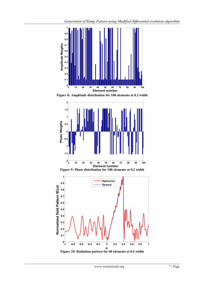
Case-2: Ramp patterns are generated at finite width (u0) 0.4 for different elements. Figure 10 represents the
radiation pattern for 60 elements, figure 11 and figure 12 reported its amplitude and phase distributions. Finally
for 100 elements radiation pattern are reported in figure 13 and corresponding amplitude, phase plots are given
in figure 14 and figure 15.
Case-3: Ramp patterns are obtained at finite width (u0)0.6 for different elements. Figure 16 shows the pattern for 60 elements, figure 17 and figure 18 reported its amplitude and phase distribution plots. Similarly for 100
elements radiation patterns are reported in figure 19 and its amplitude, phase patterns are presented in figure 20
and figure 21.
As can be seen from these resultant patterns finally modified differential evolution based on harmony
search algorithm has a more robust exploration ability to reach the optimal point in the search space. Thus it
shows that the method has good ability to achieve the global minima for a non-convex problem. As can be seen
from this simulation results, the DES family are successful in reaching the optimal value with in 100,000
number of fitness evaluations (NOFE) while the GA and PSO method failed and DES requires the least NOFE
among various methods for same accuracy. Finally the best resultant optimized ramp patterns are observed for
different elements at different widths with this new algorithm.
Figure 4: Radiation pattern for 60 elements at 0.2 width
0 500 1000 1500 2000 2500 3000 3500 4000 4500 50000
0.01
0.02
0.03
0.04
0.05
0.06
0.07
0.08
0.09
0.1
number of generations
Fittn
ess v
alu
e
-1 -0.8 -0.6 -0.4 -0.2 0 0.2 0.4 0.6 0.8 10
0.1
0.2
0.3
0.4
0.5
0.6
0.7
0.8
0.9
1
u
No
rmalized
fie
ld P
att
ern
IE
(u)I
Ramp shape Pattern
Optimized
Desired

Generation of Ramp Pattern using Modified differential evolution algorithm
www.iosrjournals.org 6 | Page
Figure 5: Amplitude distribution for 60 elements at 0.2 width
Figure 6: Phase distribution for 60 elements at 0.2 width
Figure 7: Radiation pattern for 100 elements at 0.2 width
0 10 20 30 40 50 600
0.1
0.2
0.3
0.4
0.5
0.6
0.7
0.8
0.9
1
Element number
Am
plitu
de W
eig
ths
Amplitude distribution
0 10 20 30 40 50 60-2
-1.5
-1
-0.5
0
0.5
1
1.5
2
Element number
Ph
ase W
eig
ths
Phase distribution
-1 -0.8 -0.6 -0.4 -0.2 0 0.2 0.4 0.6 0.8 10
0.1
0.2
0.3
0.4
0.5
0.6
0.7
0.8
0.9
1
u
No
rma
lize
d f
ield
Pa
ttern
IE
(u)I
Ramp shape Pattern
Optimized
Desired
Generation of Ramp Pattern using Modified differential evolution algorithm
www.iosrjournals.org 7 | Page
Figure 8: Amplitude distribution for 100 elements at 0.2 width
Figure 9: Phase distribution for 100 elements at 0.2 width
Figure 10: Radiation pattern for 60 elements at 0.4 width
0 10 20 30 40 50 60 70 80 90 1000
0.1
0.2
0.3
0.4
0.5
0.6
0.7
0.8
0.9
1
Element number
Am
plitu
de W
eig
ths
Amplitude distribution
0 10 20 30 40 50 60 70 80 90 100-2
-1.5
-1
-0.5
0
0.5
1
1.5
2
Element number
Ph
as
e W
eig
ths
Phase distribution
-1 -0.8 -0.6 -0.4 -0.2 0 0.2 0.4 0.6 0.8 10
0.1
0.2
0.3
0.4
0.5
0.6
0.7
0.8
0.9
1
u
No
rma
lize
d f
ield
Pa
ttern
IE
(u)I
Ramp shape Pattern
Optimized
Desired

Generation of Ramp Pattern using Modified differential evolution algorithm
www.iosrjournals.org 8 | Page
Figure 11: Amplitude distribution for 60 elements at 0.4 width
Figure 12: Phase distribution for 60 elements at 0.4 width
Figure 13: Radiation pattern for 100 elements at 0.4 width
0 10 20 30 40 50 600
0.1
0.2
0.3
0.4
0.5
0.6
0.7
0.8
0.9
1
Element number
Am
plitu
de W
eig
ths
Amplitude distribution
0 10 20 30 40 50 60-2
-1.5
-1
-0.5
0
0.5
1
1.5
2
Element number
Ph
ase W
eig
ths
Phase distribution
-1 -0.8 -0.6 -0.4 -0.2 0 0.2 0.4 0.6 0.8 10
0.1
0.2
0.3
0.4
0.5
0.6
0.7
0.8
0.9
1
u
No
rma
lize
d f
ield
Pa
ttern
IE
(u)I
Ramp shape Pattern
Optimized
Desired

Generation of Ramp Pattern using Modified differential evolution algorithm
www.iosrjournals.org 9 | Page
Figure 14: Amplitude distribution for 100 elements at 0.4 width
Figure 15: Phase distribution for 100 elements at 0.4 width
Figure 16: Radiation pattern for 60 elements at 0.6 width
0 10 20 30 40 50 60 70 80 90 1000
0.1
0.2
0.3
0.4
0.5
0.6
0.7
0.8
0.9
1
Element number
Am
plitu
de W
eig
ths
Amplitude distribution
0 10 20 30 40 50 60 70 80 90 100-2
-1.5
-1
-0.5
0
0.5
1
1.5
2
Element number
Ph
as
e W
eig
ths
Phase distribution
-1 -0.8 -0.6 -0.4 -0.2 0 0.2 0.4 0.6 0.8 10
0.1
0.2
0.3
0.4
0.5
0.6
0.7
0.8
0.9
1
u
No
rmalized
fie
ld P
att
ern
IE
(u)I
Ramp shape Pattern
Optimized
Desired

Generation of Ramp Pattern using Modified differential evolution algorithm
www.iosrjournals.org 10 | Page
Figure 17: Amplitude distribution for 60 elements at 0.6 width
Figure 18: Phase distribution for 60 elements at 0.6 width
Figure 19: Radiation pattern for 100 elements at 0.6 width
0 10 20 30 40 50 600
0.1
0.2
0.3
0.4
0.5
0.6
0.7
0.8
0.9
1
Element number
Am
plitu
de W
eig
ths
Amplitude distribution
0 10 20 30 40 50 60-2
-1.5
-1
-0.5
0
0.5
1
1.5
2
Element number
Ph
as
e W
eig
ths
Phase distribution
-1 -0.8 -0.6 -0.4 -0.2 0 0.2 0.4 0.6 0.8 10
0.1
0.2
0.3
0.4
0.5
0.6
0.7
0.8
0.9
1
u
No
rmalized
fie
ld P
att
ern
IE
(u)I
Ramp shape Pattern
Optimized
Desired

Generation of Ramp Pattern using Modified differential evolution algorithm
www.iosrjournals.org 11 | Page
Figure 20: Amplitude distribution for 100 elements at 0.6 width
Figure 21: Phase distribution for 100 elements at 0.6 width
V. Conclusion A new algorithm Modified Differential Evolution based on Harmony Search Algorithm is applied to
the pattern synthesis of linear array elements that are spaced λ/2 distance apart a ramp shaped beam radiation
patterns are observed. It is obvious from the results presented, that the optimized results are more close to the
desired radiation patterns.In this paper the new optimization technique combines the advantages of both harmony search algorithm and differential evolution algorithm the synthesis results showed that the Modified
DE converges faster and requires less computation that the other methods.
References [1]. G.S.N. Raju, Antennas and Propagation, Pearson Education, 2005.
[2]. C. A. Balanis, Antenna Theory Analysis and Design, 2nd
Edition, John Willy & sons Inc, New York, 1997.
[3]. R. S. Elliot, Antenna theory and design, Prentice-hall, New York, 1981.
[4]. R. S. Elliot and J. G. Stern, ―A new technique for Shaped Beam Synthesis of Equispaced Arrays,‖ IEEE Trans. Antennas and
Propagation, Vol.AP-32, no. 10, pp. 1129-1133, October 1984.
[5]. R. F. Hyneman and R. M. Johnson, ―A Technique for the Synthesis of Shaped Beam Radiation Patterns with Approximately
Equal-Percentage Ripple,‖ IEEE Trans. Antennas and Propagation, Vol. AP-15, no. 6, pp. 736- 743, November. 1967.
[6]. A. Chakraborty, B.N. Das, and G. S. Sanyal, ―Beam Shaping Using Nonlinear Phase Distribution in a Uniformly Spaced Array,‖
IEEE Trans. Antennas and Propagation., Vol. AP-30, no. 5, pp. 1031-1034, September. 1982
[7]. W.L.Stutzman, ―Synthesis of Shaped-Beam Radiation patterns using Iterative Sampling Method,‖ IEEE Transactions on
Antennas and Propagation, Vol. AP-19, no.1, pp. 36-41, January. 1971.
[8]. A.Sudhakar, G.S.N.Raju, K.R. Gottumukkala , ―Generation of Ramp type of Radiation patterns from an array antennas,‖
National Journal of EMC, Vol. 2, no.1&2, pp. 5-12, April and October 1998.
[9]. A.Sudhakar, P.Saritha, M. DilipChakravarthy, G.S.N.Raju, K.R.Gottumukkala,― Optimized Ramp patterns,‖ AMSE Journal,
France (Accepted)
[10]. G.S.N.Raju, A.Sudhakar, K.R. Gottumukkala, Ajay Chakraborty, ―Realization of Ramp and Stair-Step Patterns using Phase only
control technique,‖ I.E.T.E. Research Journal (Communicated).
0 10 20 30 40 50 60 70 80 90 1000
0.1
0.2
0.3
0.4
0.5
0.6
0.7
0.8
0.9
1
Element number
Am
plitu
de
We
igth
s
Amplitude distribution
0 10 20 30 40 50 60 70 80 90 100-2
-1.5
-1
-0.5
0
0.5
1
1.5
2
Element number
Ph
as
e W
eig
ths
Phase distribution

Generation of Ramp Pattern using Modified differential evolution algorithm
www.iosrjournals.org 12 | Page
[11]. A.Sudhakar, G.S.N.Raju, G.K.Raju, ―Generation of Ramp patterns using Amplitude control,‖ Proc. of FACT-2K, pp. 43-48,
Feb.2000.
[12]. M.J. Buckley, Synthesis of Shaped Beam Antenna Patterns using Implicitly Constrained current elements, IEEE Trans.
Antennas and Propagation., Vol. AP-44, pp. 192-197, 1996.
[13]. Akdagli, A. and K. Guney, ―Shaped-Beam Pattern Synthesis of Equally and Unequally Spaced Linear Antenna Arrays using a
Modified Tabu Search Algorithm,‖ Microwave Opt. Technol. Lett.,Vol. 36, No. 1, pp. 16-20, January 2003.
[14]. V. Rajya Lakshmi, and G.S.N.Raju, ―Amplitude only Pattern Synthesis of Arrays Using Genetic algorithms,‖ International
Journal of Engineering Science and Technology (IJEST), ISSN: 0975-5462, Vol. 3, no. 5, May 2011.
[15]. Zaharis, Z. D. and T. V. Yioultsis, ―A Novel Adaptive Beamforming Technique applied on Linear Antenna Arrays using
Adaptive Mutated Boolean PSO,‖ Progress In Electromagnetics Research, Vol. 117, pp. 165-179, 2011
[16]. Liu, Y., Z.-P. Nie, and Q. H. Liu, ―A New Method for the Synthesis of Non-uniform Liner Arrays with Shaped Power Patterns,‖
Progress In Electromagnetics Research, Vol. 107, pp. 349-363, 2010.
[17]. Guney, K. and S. Basbug, ―Interference Suppression of Linear Antenna Arrays by Amplitude-only control using Bacterial
Foraging Algorithm,‖ Progress In Electromagnetics Research, Vol. 79, pp. 475-497, 2008.
[18]. Basu, B. and G. K. Mahanti, Fire fly and Artificial Bees Colony algorithm for Synthesis of Scanned and Broad-side Linear array
Antenna,‖ Progress In Electromagnetics Research, Vol. 32, pp. 169-190, 2011.
[19]. Rainer Storn and Kenneth Price, ‗Minimizing the Real Functions of the ICEC‘96 contest by Differential Evolution,‖ IEEE Trans.
Antennas Propag., pp. 842-845, May 1996.
[20]. R.StornandK.Price,―Differentialevolution—Asimpleandefficientheuristicforglobaloptimizationovercontinuousspaces,‖Journal
ofGlobalOptimization,vol.11, no. 4, pp.341–359,1997.
[21]. R. Li, L. Xu, X.-W. Shi, N. Zhang, and Z. –Q. Lv, ―Improved Differential Evolution Strategy for Antenna Array Pattern
Synthesis problems,‖ Progress In Electromagnetics Research, Vol. 113, pp. 429-441, February 2011.
[22]. A. Mandal, H. Zafar, S.Das, and A. Vasilakos, ―A Modified Differential Evolution Algorithm for Shaped Beam Linear Array
Antenna Design,‖ Progress In Electromagnetics Research, Vol. 125, pp. 439-457, March 2012.
[23]. Yikai Chen, Shiwen Yang, ZaipingNie, ―The Application of a Modified Differential Evolution Strategy to Some Array Pattern
Synthesis Problems,‖ IEEETrans.AntennasPropag.,vol. 56, no.7, pp. 1919-1927 july 2008.
[24]. Fenggan Zhang, WeiminJia, and Minli Yao, ―Linear Aperiodic Array Synthesis Using Differntial Evolution Algorithm,‖
IEEETrans.AntennasPropag.,vol. 12, no.7, pp. 797-800 july 201
T. Vidhya Vathireceived the Bachelor of Technology in Electronics and
Communication Engineering in the year of 2006 from JNTU Hyderabad and the Master
of Technology in Radar and Microwave Engineering in 2008 from Andhra University
College of Engineering (A). Currently, she is working towards her PhD degree in the
department of Electronics and Communication Engineering, Andhra University College
of Engineering (A). Her Research interests include Array Antennas, EMI/EMC and Soft
Computing. She is a life member of SEMCE (India).
Dr. G.S.N. Raju received his B.E., M.E. with distinction and first rank from Andhra
University and Ph.D. from IIT, Kharagpur. At present, he is the Vice – Chancellor of
Andhra University and a Senior Professor in Electronics and Communication
Engineering. He is in teaching and research for the last 30 years in Andhra University.
He guided 28 Ph.D.s in the fields of Antennas, Electromagnetics, EMI/EMC and
Microwave, Radar Communications, Electronic circuits. Published about 304 technical
papers in National/ International Journals/ Conference Journals and transactions. He is
the recipient of The State Best Teacher Award‘ from the Government of Andhra Pradesh
in 1999, ‗The Best Researcher Award‘ in 1994, ‗Prof. Aiya Memorial National IETE
Award‘ for his best Research guidance in 2008 and Dr. SarvepalliRadhakrishnan Award for the Best
Academician of the year 2007, He was a visiting Professor in the University of Paderborn and also in the University Karlsruhe, Germany in 1994. He held the positions of Principal, Andhra University College of
Engineering (A), Visakhapatnam, Chief Editor of National Journal of Electromagnetic Compatibility. Prof. Raju
has published five textbooks Antennas and Wave Propagation, Electromagnetic Field Theory and Transmission
Lines, Electronics Devices and Circuits, Microwave Engineering, Radar Engineering and Navigational Aids.
Prof. Raju has been the best faculty performer in Andhra University with the performance index of 99.37%.