geophys rpt on the carr tp claim group
TRANSCRIPT
42A09SW0035 2.15975 CARR 010
GEOPHYSICAL REPORTFOR
PENTLAND FIRTH VENTURES LTD.ON THE
CARR TOWNSHIP CLAIM GROUPL-1189529
NORTHEASTERN, ONTARIO
1597 5
RECEIVED
MAY - 11995
MINING LANDS BRANCH
PREPARED BY: John C. Grant, GET FGAC March 1995
42A09SW0035 2.15975 CARR /-j * pjp
TABLE OF CONTENTS
PAGE
INTRODUCTION........................................l
PROPERTY LOCATION AND ACCESS........................l
CLAIM BLOCK. . . . . . . . . . . . . ... . . . . . . . . . . . . . . . . . . . . . . . . .l
PERSONNEL...........................................l
LINECUTTING PROGRAM.................................2
GEOPHYSICAL PROGRAM.................................2
MAGNETIC SURVEY. . . . . . . . . . . . . . . . . . . . . . . . . . . . . . . . . . . . .2
IP SURVEY...........................................2
SURVEY RESULTS......................................3
CONCLUSIONS AND RECOMMENDATIONS.....................3
CERTIFICATE
FIGURES l- LOCATION MAP2- PROPERTY LOCATION3- CLAIM SKETCH
APPENDIX A - EDA OMNI IV SYSTEMB - EDA IP-4 RECEIVER, SCINTREX IPC-7,2.5KW TRANSMITTER
MAPS- MAGNETIC SURVEY- PSEUDO SECTION 5200 EAST- PSEUDO SECTION 5400 EAST- PSEUDO SECTION 5600 EAST
Page l
INTRODUCTION
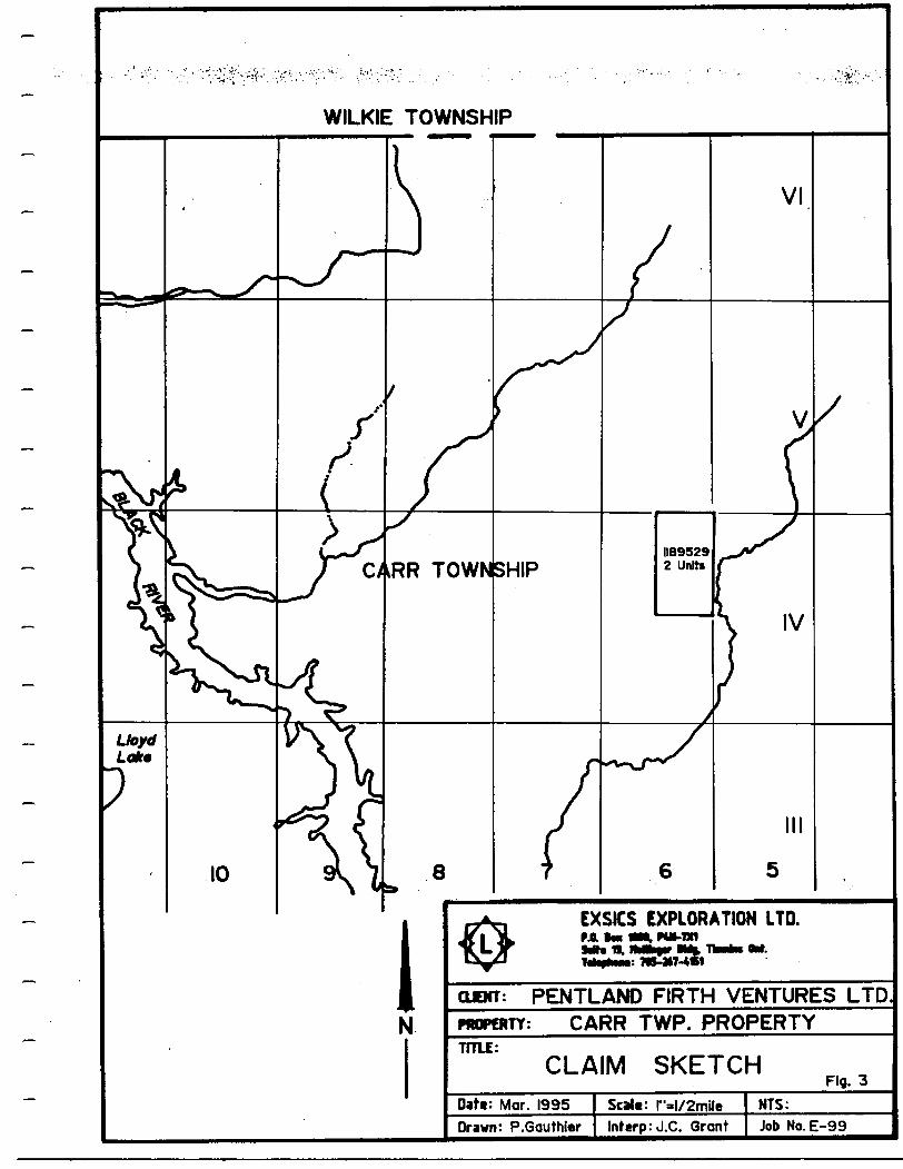
The services of Exsics Exploration Limited were retained by Pentland Firth Ventures Ltd. to complete a linecutting and geophysical program over a block of 2 claims located in the northeast half of Lot 6 Concession IV of Carr Township.
The purpose of the program was to test the properties potential for structural horizon which would represent favourable area for gold deposition.
The linecutting began on September 2, 1994 and was completed by September 10, 1994. The geophysics began September 28, 1994 and was completed by October 8, 1994.
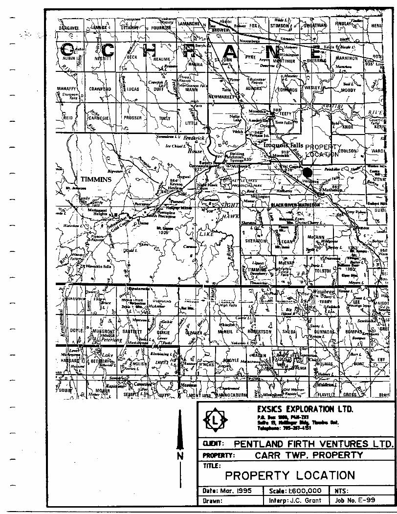
PROPERTY LOCATION AND ACCESS
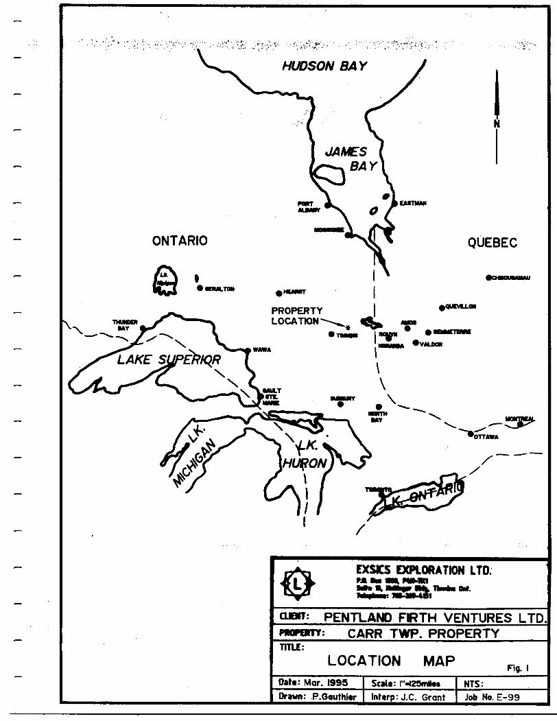
The claim unit is located in the northeast half of Lot 6, Concession IV of Carr Township of the Larder Lake Mining Division in northeastern Ontario. Figure l and 2.
Access to the group was ideal, Highway 101 east travels through Matheson and continues east to the Quebec Border. Following Highway 101 east from Matheson, across the Black River, will bring one to the intersection of a good gravel road travelling north between Lots 4 and 5 of Carr Township which provides two wheel vehicle access to the east boundary of the block. A secondary road travels west off of the gravel road and provides access to the northeast corner of the claim group.
CLAIM BLOCK
The claim number which represents the 2 units covered by this survey is L-1189529. Refer to Figure 3 of this report.
PERSONNEL
The field crew directly involved with collecting all of the field data were as follows:
Richard Mathieu Operator Timmins, Ontario Robin Mathieu Assistant Timmins, Ontario Lance Tipler Helper Timmins, Ontario Frank Dimarco Helper Timmins, Ontario
All of the work was completed under the direct supervison of J. C. Grant. Drafting and computer compilation was handled by P. Gauthier of Exsics.
PROPERTY LOCATION
EXSCS EXPLORATION LTD.• *i
: PENTLAND FKTH VENTURES LTD CARR TWP. PROPERTY
TITLE:
LOCATION MAP Rg. lData: Mar. 1995
Drawn: P.GouthiwScati: l"H29ml*sInterp: J.C. Grqnt
NTS:Job No. E-99
————CTtMwti- -W-v"o FOUflNAB
Btfttfl
EXSICS EXPLORATION 1TD.P JL VM Ml, MN-IXt SriNfl.
7K-VT-4r-*w
OBIT: PENTLAND FIRTH VENTURES LTDPROPERTY: CARR TWP. PROPERTYTITLE:
PROPERTY LOCATIONDaft: Mar. 1995Drawn:
Scalt: 1:600,000lnferp:J.C. Grant
NTS:Job No. E-99
WILKIE TOWNSHIP
CARR TOWNSHIP
EXSICS EXPLORATION LTD.f A. BM Mil PUMX1^-J*- *Bt |^J|M^^^ l^fe 19VTV U^ IIHlMMiw •MBBJr l
Mm
OBIT: PENTLAND FIRTH VENTURES LTDPROPERTY: CARR TWP. PROPERTYTITLE:
CLAIM SKETCHFig. 3
Date Mar. 1995Drawn: P.Gauthier
Scalt: r-IX2mileInrerp: J.C. Grant
NTS:Job No. E-99
Page 2
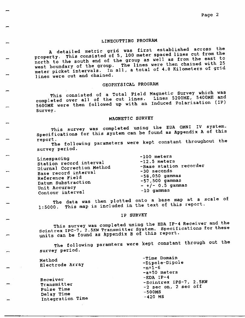
LINECUTTING PROGRAM
A detailed metric grid was first established across the
property. This consisted of 5, 100 meter spaced lines cut from the
north to the south end of the group as well as from the east to
west boundary of the group. The lines were then chained with 25
meter picket intervals. In all, a total of 4.8 Kilometers of grid
lines were cut and chained.
GEOPHYSICAL PROGRAM
This consisted of a Total Field Magnetic Survey which was
completed over all of the cut lines. Lines 5200ME, 5400ME and
5600ME were then followed up with an Induced Polarization (IP)
Survey.
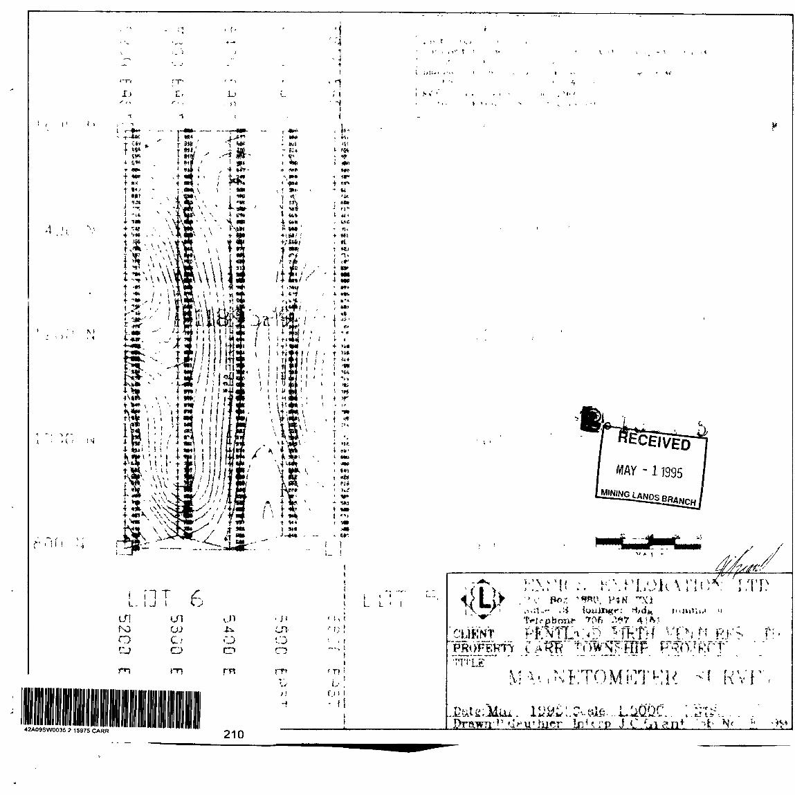
MAGNETIC SURVEY
This survey was completed using the EDA OMNI IV system.
Specifications for this system can be found as Appendix A of this
report.The following parameters were kept constant throughout the
survey period.
LinespacingStation record interval Diurnal Correction Method Base record interval Reference Field Datum Substraction Unit Accuracy Contour interval
-100 meters-12.5 meters-Base station recorder-30 seconds-58,050 gammas-57,500 gammas- * /- 0 .5 gammas-10 gammas
The data was then plotted onto a base map at a scale of
1:5000. This map is included in the text of this report.
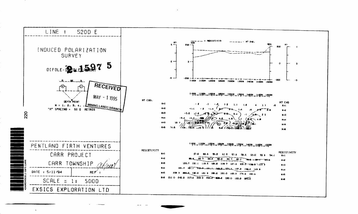
IP SURVEY
This survey was completed using the EDA IP-4 Receiver and the
Scintrex IPC-7, 2.5KW Transmitter System. Specifications for these
units can be found as Appendix B of this report.
The following paramters were kept constant through out the
survey period.
Method Electrode Array
Receiver Transmitter Pulse Time Delay Time Integration Time
Time DomainDipole-Dipolen^-63=50 metersEDA IP-4Scintrex IPS-7, 2.5KW2 sec on, 2 sec off500MS420 MS
Page 3
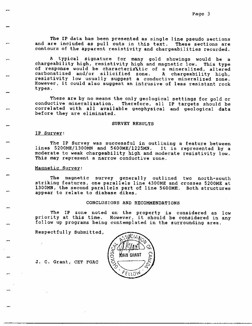
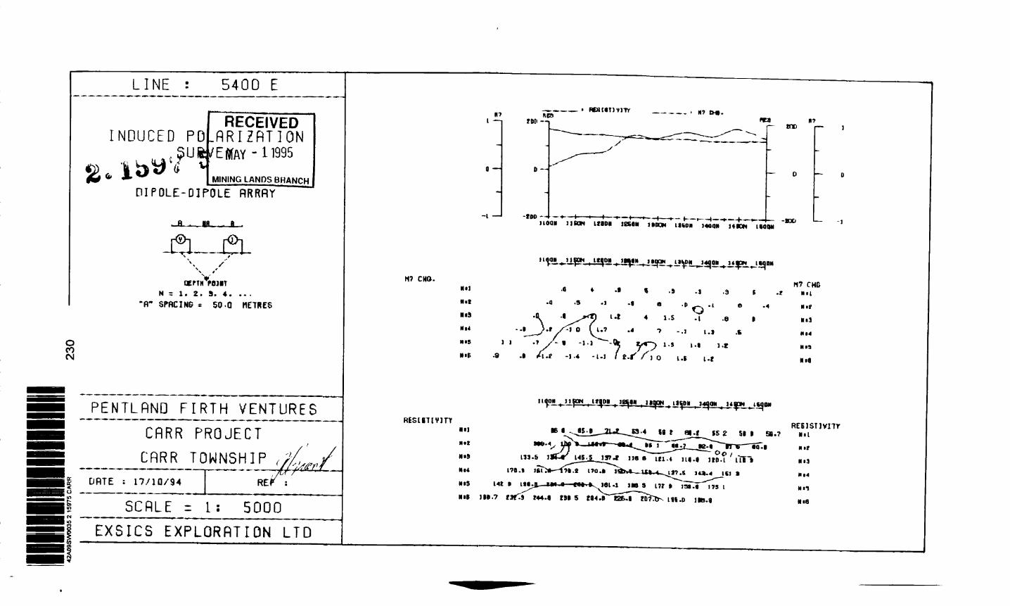
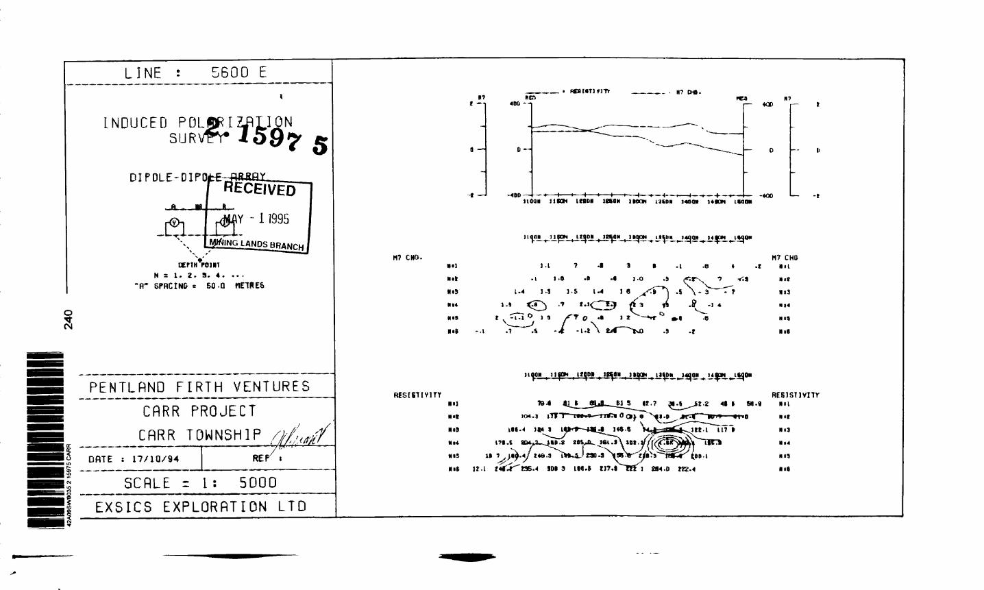
The IP data has been presented as single line pseudo sections and are included as pull outs in this text. These sections are contours of the apparent resistivity and chargeabilities recorded.
A typical signature for many gold showings would be a chargeability high, resistivity high and magnetic low. This type of response would be characteristic of a mineralized, altered carbonatized and/or silicified zone. A chargeability high, resistivity low usually suggest a conductive mineralized zone. However, it could also suggest an intrusive of less resistant rock types.
These are by no means the only geological settings for gold or conductive mineralization. Therefore, all IP targets should be correlated with all available geophysical and geological data before they are eliminated.
SURVEY RESULTS
IP Survey;
The IP Survey was successful in outlining a feature between lines 5200ME/1300MN and 5600ME/1225MN. It is represented by a moderate to weak chargeability high and moderate resistivity low. This may represent a narrow conductive zone.
Magnetic Survey;
The magnetic survey generally outlined two north-south striking features, one parallels line 4300ME and crosses 5200ME at 1300MN, the second parallels part of line 5600ME. Both structures appear to relate to diabase dikes.
CONCLUSIONS AND RECOMMENDATIONS
The IP zone noted on the property is considered as low priority at this time. However, it should be considered in any follow up programs being contemplated in the surrounding area.
Respectfully Submitted,
J. C. Grant, GET FGAC

CERTIFICATE
I, John C. Grant, hereby certify that:
1) I am a graduate geophysicist (1975) of the three year program in Geological Technology at Cambrian College of Applied Arts and Technology, Sudbury, Campus. I have worked subsequentely as an Exploration Geophysicist for Teck Exploration Limited (5 years), North Bay office, and as Exploration Manager and Geophysicist for Exsics Exploration Limited from 1980 to present.
2) I am a Member of the Certified Engineering Technologist Association since 1984.
3) I am a member of the Geological Association of Canada.
4) I have been actively engaged in my profession for the last twenty (20) years, including all aspects of exploration studies, surveys and interpretations.
5) I have no specfic or special interest in the described property. I have been retained as a Consulting Geophysicist, for property appraisal.
John Charles Grant, GET, FGAC
APPENDIX
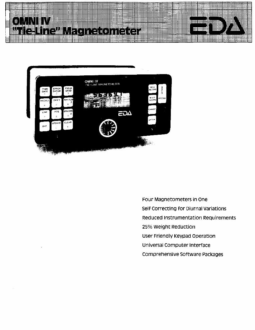
Four Magnetometers in OneSelf Correcting for Diurnal VariationsReduced instrumentation Requirements250Xo Weight ReductionUser Friendly Keypad OperationUniversal Computer interfaceComprehensive Software Packages
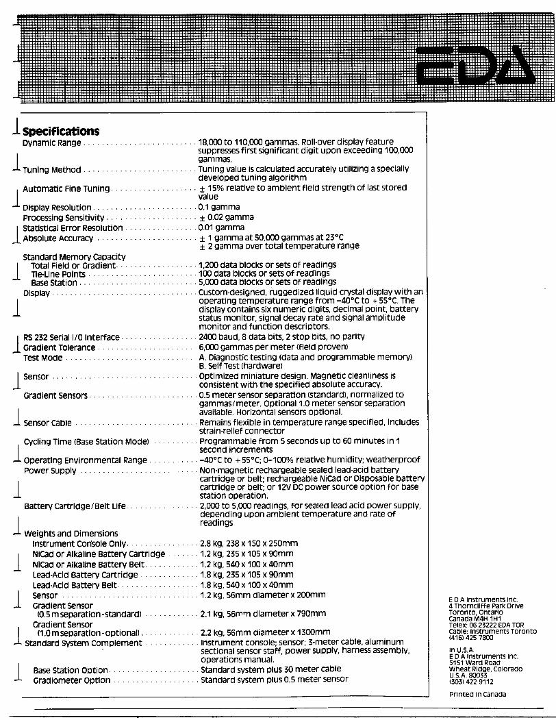
l specificationsDynamic Range......................... 18,000 to 110,000 gammas. Roll-over display feature
suppresses first significant digit upon exceeding 100,000 gammas.
-J- Tuning Method ......................... Tuning value is calculated accurately utilizing a speciallydeveloped tuning algorithm
i Automatic Fine Tuning................... ± 15070 relative to ambient field strength of last storedvalue
-*- D isplay Resolution....................... 0.1 gammaProcessing Sensitivity.................... ± 0.02 gamma
i Statistical Error Resolution ................ 0.01 gammaJ, Absolute Accuracy ...................... ± 1 gamma at 50,000 gammas at 230 C
± 2 gamma over total temperature rangeStandard Memory Capacity
l Total Field or Gradient.................. 1,200 data blocks or sets of readingsl Tie-Line Points ........................ 100 data blocks or sets of readings
Base Station .......................... 5,000 data blocks or sets of readingsDisplay ................................ Custom-designed, ruggedized liquid crystal display with an
i operating temperature range from -400 C to + 55 0C. The l display contains six numeric digits, decimal point, battery
status monitor, signal decay rate and signal amplitude monitor and function descriptors,
i RS 232 Serial I/O interface ................ 2400 baud, 8 data bits, 2 stop bits, no parityJ. Gradient Tolerance ...................... 6,000 gammas per meter (field proven)
Test Mode ............................. A. Diagnostic testing (data and programmable memory)B. self Test (hardware)
l Sensor................................ optimized miniature design. Magnetic cleanliness isJ. consistent with the specified absolute accuracy.
Gradient Sensors........................ 0.5 meter sensor separation (standard), normalized togammas/meter, optional 1.0 meter sensor separation
l available. Horizontal sensors optional.-L Sensor Cable ........................... Remains flexible in temperature range specified, includes
strain-relief connector Cycling Time (Base Station Mode) .......... Programmable from 5 seconds up to 60 minutes in 1
second increments J- Operating Environmental Range ........... -400 C to n-55 0 C; Q-100% relative humidity; weatherproof
Power Supply ........... ...... ... ..... Non-magnetic rechargeable sealed lead-acid battery, cartridge or belt; rechargeable NiCad or Disposable battery
cartridge or belt; or 12V DC power source option for base-i station operation.
Battery cartridge l Belt Life ..... .......... 2,000 to 5,000 readings, for sealed lead acid power supply,depending upon ambient temperature and rate of readings
-L weights and Dimensionsinstrument Console Only. . . .. .. 2.8 kg, 238 x 150 x 250mmNiCad or Alkaline Battery Cartridge . 1.2 kg, 235 x 105 x 90mm NiCad or Alkaline Battery Belt ...... . 1.2 kg, 540 x 100 x 40mmLead-Acid Battery Cartridge ............. 1.8 kg, 235 x 105 x 90mmLead-Acid Battery Belt..... ............ 1.8 kg, 540 x 100 x 40mm
l Sensor .............................. 1.2 kg, 56mm diameter x 200mm- j. ^.- E D A instruments inc.
J- Gradient Sensor 4 Thomcliff e Park Drive(0.5 m separation-standard) . ... .. . 2.1 kg, 56mm diameter x 790mm Toronto Ontario
— .. , f^ C3n3Q3 n/IAH 1H1Gradient Sensor Telex: os 23222 EDA TOR
(1.0 m separation-optional). . . . 2.2 kg, 56mm diameter x 1300mm cable: instruments TorontoJ- Standard System complement ............ instrument console; sensor; 3-meter cable, aluminum
sectional sensor staff, power supply, harness assembly, m U.S.A.nnprafinnc mani lal EDA Instruments inc.operations manual. 5151 ward Road
Base Station Option.. ...... ............ standard system plus 30 meter cable wheat Ridge, Colorado-L Gradiometer Option ................... standard system plus 0.5 meter sensor (U303?422 )9ti2
Printed in Canada
APPENDIX B
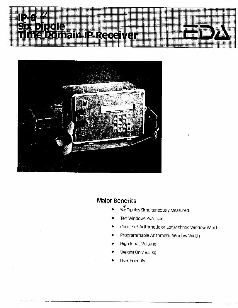
Major Benefits^
* SsrDipoles Simultaneously Measured
* Ten Windows Available
* Choice of Arithmetic or Logarithmic Window Width* Programmable Arithmetic Window Width* High Input Voltage
* Weighs Only 8.5 kg.
* User Friendly
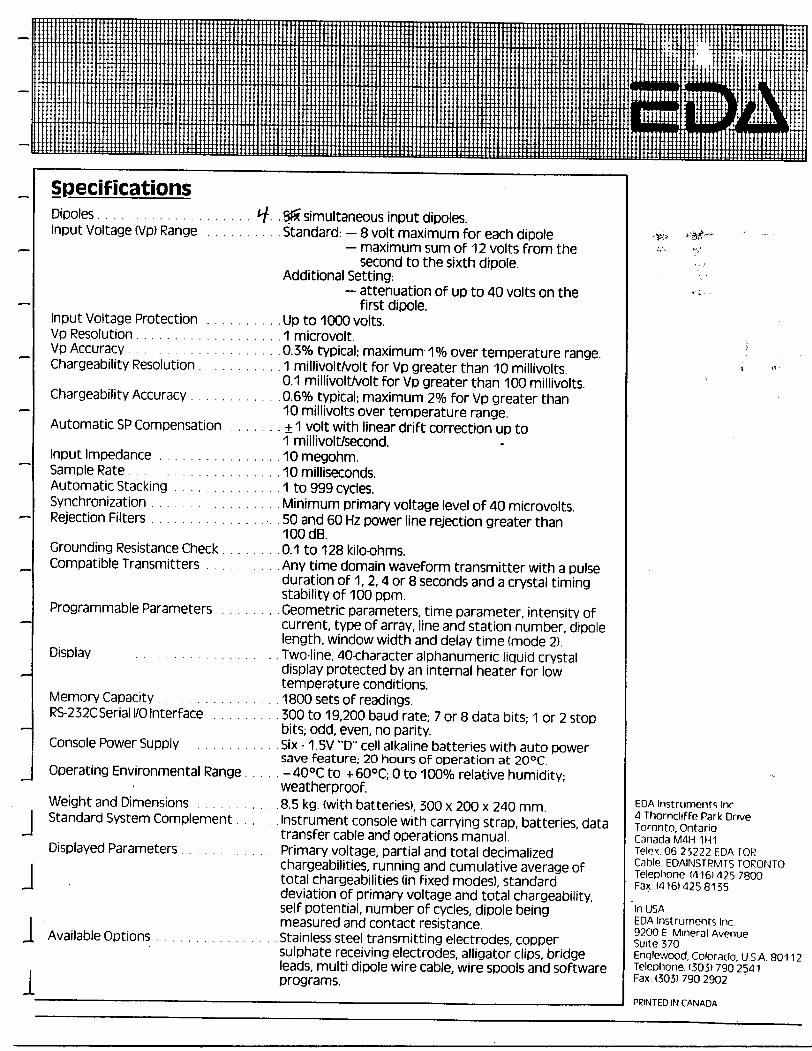
SpecificationsDipoles. . . . . . . . . . . . . . . . . . . . A/. .S?5fsimultaneous input dipoles.Input Voltage (Vp) Range . . . . . . . . .Standard: —8 volt maximum f or each di pole
— maximum sum of 12 volts from thesecond to the sixth dipole.
Additional Setting:— attenuation of up to 40 volts on the
first dipole. Input Voltage Protection . . . . . . . . . .Up to 1000 volts.Vp Resolution. .. .. . . . . . . . . . . . . . . 1 microvolt. :Vp Accuracy . . . . . . . . . . .Q.3% typical; maximum-1 "ft over temperature range.Chargeability Resolution. . . . . . . . . . 1 millivolt/volt for Vp greater than 10 millivolts.
0.1 millivolt/volt for Vp greater than 100 millivolts. Chargeability Accuracy . . . . . . . . . . . Q.6% typical; maximum 207o for Vp greater than10 millivolts over temperature range.
Automatic SP Compensation . . . . . . ± 1 volt with linear drift correction up to1 millivolt/second.
Input Impedance . . . . . . . . . . . . . . . 10 megohm.Sample Rate . . . . . . . . . . . 10 milliseconds.Automatic Stacking . . . . . . . . . . . . . . 1 to 999 cycles.Synchronization . . . . . . . . . . . . Minimum primary voltage level of 40 microvolts.Rejection Filters . . . . . . . . . . . . . . ... . 50 and 60 Hz power line rejection greater than
100 dB. Grounding Resistance Check. . . . . . . .0.1 to 128 kilo-ohms.Compatible Transmitters . . . . . . . . . . Any time domain waveform transmitter with a pulse
duration of 1,2,4 or 8 seconds and a crystal timingstability of 100 ppm.
Programmable Parameters . . . . . . .. Geometric parameters, time parameter, intensity ofcurrent, type of array, line and station number, dipolelength, window width and delay time (mode 2). Display . . . . . . . . . . . . . . . . . .Two-line, 40-character alphanumeric liquid crystaldisplay protected by an internal heater for lowtemperature conditions.
Memory Capacity . . . . . . . . . . . . . . 1800 sets of readings.RS-232C Serial I/O Interface . . . . . . . . . 300 to 19,200 baud rate; 7 or 8 data bits; 1 or 2 stop
bits; odd, even, no parity. Console Power Supply . . . . . . . . . .Six-1.5V "D" cell alkaline batteries with auto powersave feature; 20 hours of operation at 200C. Operating Environmental Range. . . . . -400C to -t-600C; O to 10007o relative humidity;
weatherproof. Weight and Dimensions . . . . . . . . . . . 8.5 kg. (with batteries), 300 x 200 x 240 mm. 4.J Standard System Complement. . . . . . Instrument console with carrying strap, batteries, data Toronto. Ontario
transfer cable and operations manual. canada IVWH Displayed Parameters. . . . . . . . . . . . . Primary voltage, partial and total decimalized I"*" ^5222LEDA IOKrharapahilitipq rimnina and nimiilarivp avpraap nf Cable EDAINSTRMFS TORONTO l cnargeaoiiities, runnng ana cumulative average or Telephone MIGI 125 7soototal chargeability (m fixed modes), standard Fax: w iei 425 ei 55 J deviation of primary voltage and total chargeability,self potential, number of cycles, dipole being ln USAi mpasi irprl anrl rnnrarr rpckfanrp EDA instruments Inc.measurea ana contact resistance. 9200 E. Mineral AvenueJ. Available Options . . . . . . . . . . . . . . . .Stainless steel transmitting electrodes, copper Suite 370sulphate receiving electrodes, alligator clips, bridge Engiewood, Colorado, u s A. 80112leads, multi dipole wire cable, wire spools and software Telephone: 13031790 2541l programs. Fax ( 303) 790 2902
-^ PRINTED IN CANADA
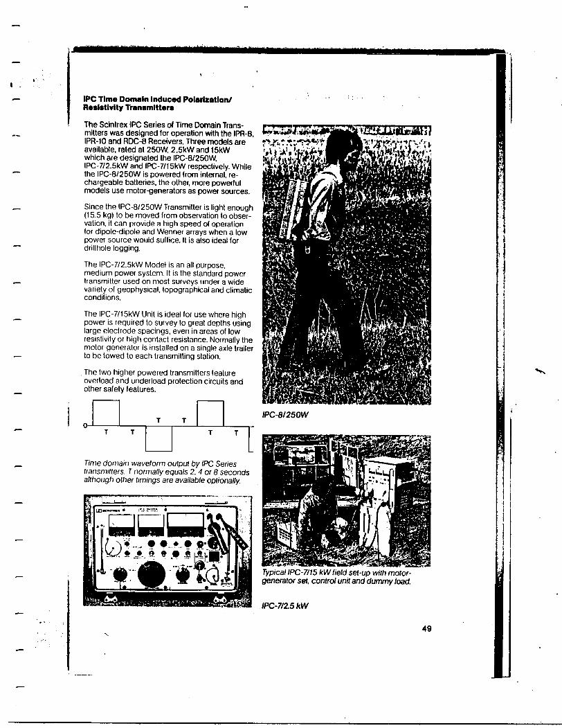
IPC Time Domain Induced Polarization/ Resistivity TVansmlttera
The Scintrex IPC Series of Time Domain Trans mitters was designed for operation with the IPR-8. IPR-10 and RDC-8 Receivers. Three models are available, rated at 250W, 2.5KW and 15kW which are designated the IPC-8/250W. IPC-7/2.5KW and IPC-7/15RW respectively. While the IPC-8/250W is powered from internal, re chargeable batteries, the other, more powerful models use motor-generators as power sources.
Since the IPC-8/250W Transmitter is light enough (15.5 kg) to be moved from observation to obser vation, it can provide a high speed of operation for dipole-dipole and Wenner arrays when a low power source would suffice. It is also ideal for drillhole logging.
The IPC-7/2.5RW Model is an all purpose, medium power system. It is the standard power transmitter used on most surveys under a wide variety of geophysical, topographical and climatic conditions.
The IPC-7/15KW Unit is ideal for use where high power is required to survey to great depths using large electrode spacings, even in areas of low resistivity or high contact resistance. Normally the motor-generator is installed on a single axle trailer to be towed to each transmitting station.
The two higher powered transmitters feature overload and underload protection circuits and other safety features.
T T0- ————————— i T T
Time domain waveform output by IPC Series transmitters. T normally equals 2.4 or 8 seconds although other timings are available optionally.
L)
IPC-8/250W
Typical IPC-7/15 kWlield set-up with motor- generator set. control unit and dummy load.
/PC-7/2.5 kW
49
Ministry ofBkftdh^aWA^^ *^— - - — *^-—- — ——-*FwnnpfTi uvwopnwni.-.—.^a •nQ
Ontario
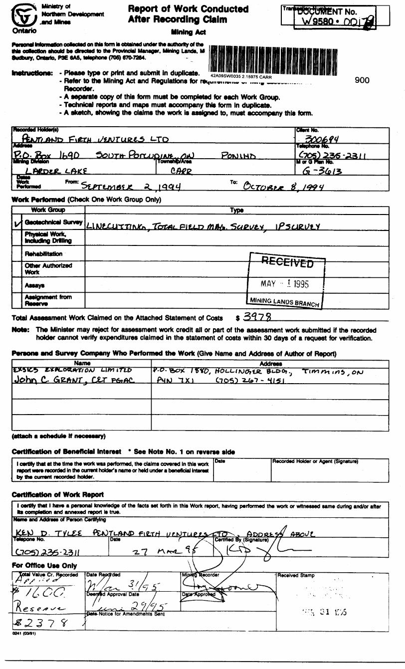
Report of Work Conducted After Recording Claim
Mining Act
NT No W9580 *
P^iund Intomatauoaerlert on IMs form to obtainedM* ootsctton should b* olreeted to the Provincial Manager. Mining Lands, MSudbury, Ontario. P3E 6A5. lelsphons (70S) 670-7264.
Please type or print and submit In duplicate.Refer to the Mining Act and Regulations forRecorder.A separate copy of this form must be completed for each Work Group.Technical reports and maps must accompany this form in duplicate.A sketch, showing the claims the work is assigned to, must accompany this form.
900
FM ara *-ToC*wrt No*
From: To:
Work Performed (Check One Work Group Only)WorkGroup Type
Qeotechnicai Surveytifrtrl,-wooc,
mdurjno Drillng
Rehabilitation
Other Authorized
Assays
Total Assessment Work Claimed on the Attached Statement of CostsThe Minister may reject for assessment work credit all or part of the assessment work submitted if the recorded holder cannot verify expenditures claimed in the statement of costs within 30 days of a request for verification.
Persons and Survey Company Who Performed the Work (Give Name and Address of Author of Report)Name Address
94-00,.Johr\ CJLT PMU TXJ
(attach a eehedule If necessary)
Certification of Beneficial Interest * See Note No. 1 on reverse sidel certify that at the time the work was performed, the claims covered in this work
by the current recorded holder.
Date Recorded Holder or Agent (Signature)
Certification of Work Report
0941 (03/91)
l
f!r 5*N -o
fi
iHf
1!
a*j od1ttvJ QO
^
S
8 IN
Qs|* tiff
n
K u•^ -xvj
W
Reserv Work to Claimed a Future
P*
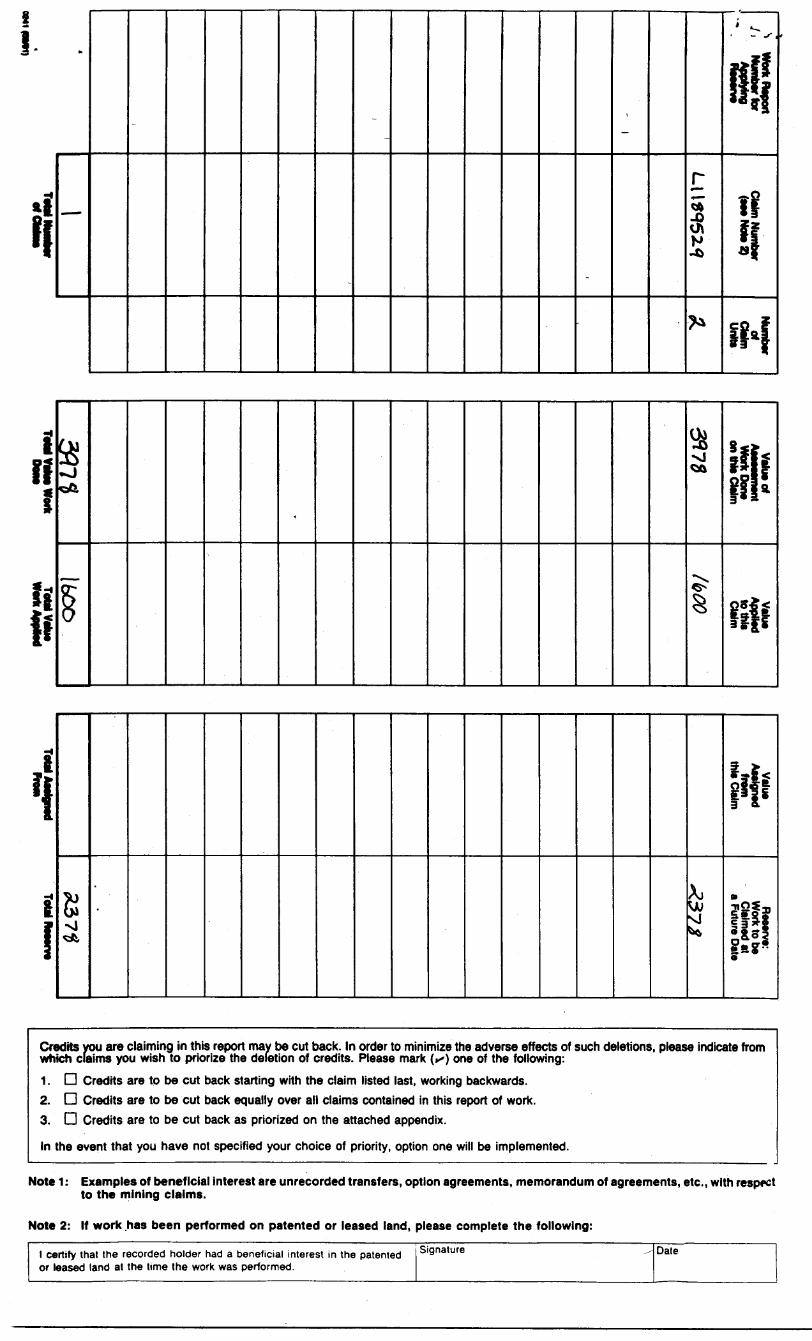
Credits you are claiming in this report may be cut back. In order to minimize the adverse effects of such deletions, please indicate from which claims you wish to priorize the deletion of credits. Please mark (^) one of the following:1. D Credits are to be cut back starting wKh the claim listed last, working backwards.2. D Credits are to be cut back equally over all claims contained in this report of work.3. D Credits are to be cut back as priorized on the attached appendix.
In the event that you have not specified your choice of priority, option one will be implemented.
Note 1: Examples of beneficial interest are unrecorded transfers, option agreements, memorandum of agreements, etc., with respect to the mining claims.
Note 2: If work has been performed on patented or leased land, please complete the following:
1 certify that the recorded holder had a beneficial interest in the patented or leased land at the time the work was performed.
Signature Date
Northern Development•IflQ MlO^S
*Mintsteredu Developpecnent du Nocd et dee mines
for Assessment Credit6tat des coOts aux fins du credit devaluation
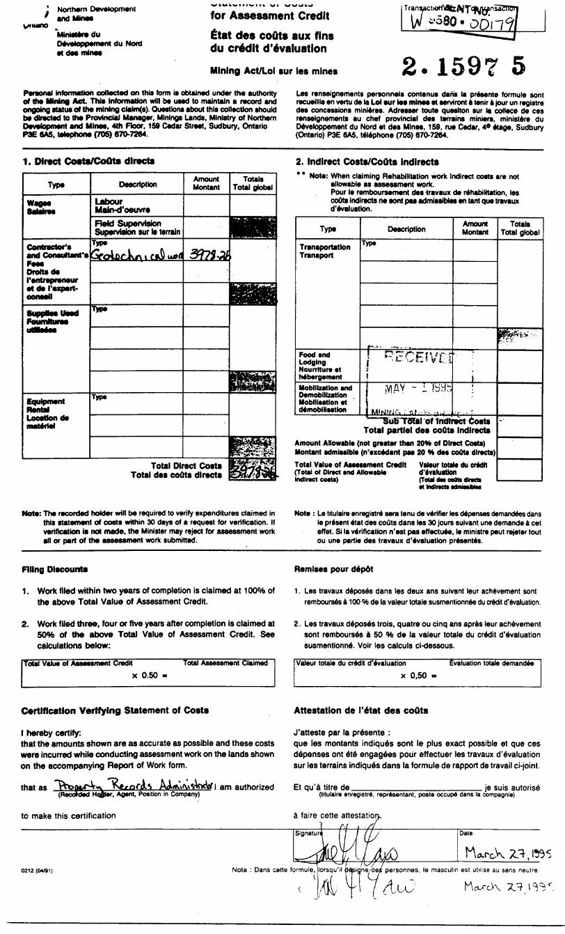
Mining Act/Lot sur les mines 2.1597 5Personal Information collected on this form is obtained under the authority of the Mining Act This Information will be used to maintain a record and ongoing status of the mining daim(s). Questions about this collection should be directed to the Provincial Manager, Minings Lands. Ministry of Northern Development and Minee. 4th Floor. 159 Cedar Street. Sudbury. Ontario P3E 6A5, telephone (705) 670-7264.
Les renseignements personnels contenus dans la presents formule son! recueillis en vertu de la Lol sur lee minee et serviront a tenir a jour un registre des concessions minieres. Adresser toute question sur la cotlece de ces renseignements au chef provincial des terrains miniers. ministers du Developpement du Nord et des Mines, 159. rue Cedar. 4* etage, Sudbury (Ontario) P3E 6A5, telephone (705) 670-7264.
1. Direct Costs/CoOts directs
Type
Contractor's and Coneuttanfe
Drottade ('entrepreneur et de I'axpert-
Foumlturae
Equlpmerrt Rental Location de
Description
Labour Main-d'oeuvreField Supervision Supervision sur le terrain
Type
t CiA
nrjipe
Type
Amount Montant
Totals Total global
3375*.
Total Direct Costs Total des coOts directs
2. Indirect Costs/CoOts Indlrects* * Note: When claiming Rehabilitation work Indirect costs are not
allowable as assessment work. Pour le remboursement des iravaux de rehabilitation, les coOts indlrects ne sont pas admissiWes en tant que travaux d'evaluation.
Type
Transportation Transport
Food and Lodging Nourrlture et hebergementMobilization and Demobilization Mobilisation et demobilisation
Description
Typ*
l^ p^' pVV - r
I sViAY ~ I b'Hr,
Amount Montant
Totals Total global
P^v,-,:
i
•r . - '
' — SuBTdlal of Indirect Costs Total partial des coOts Indlrects
Amount Allowable (not greater than 20H of Direct Costa) Montant admissible (n'excedant pas 20 H des couts directs)Total Value of Assessment Credit Valeur totale du credit (Tout of Direct and Allowable d'evaluation Indirect co*U) (Total dee cotte dlracts
~*
Note: The recorded holder will be required to verify expenditures claimed in this statement of costs within 30 days of a request for verification. If verification is not made, the Minister may reject for assessment work an or part of the assessment work submitted.
Note : Le titulaire enregistre sera tenu de verifier les depenses demandees dans le present etat des couts dans les 30 jours suivant une demande a eel effet. Si la verification n'est pas effectuee, le ministre peut rejeter tout ou une partie des travaux devaluation presentes.
Filing Discount* Remises pour depot
1. Work filed within two years of completion is claimed at 1OOlfe of the above Total Value of Assessment Credit.
1. Les travaux deposes dans les deux ans suivant leur achevement sont rembourses a 100 "ft de la valeur totale susmentionnee du credit d'evaluation,
2. Work filed three, four or five years after completion is claimed at 50*ft of the above Total Value of Assessment Credit. See calculations below:
Tout Value of Assessment Credit Total Assessment Claimedx 0.50
2. Les travaux deposes trois, quatre ou cinq ans apres leur achevement sont rembourses a 50 •ft de la valeur totale du credit d'evaluation susmentionne. Voir les calculs ci-dessous.
Valeur totale du credit d'evaluation Evaluation totale demandeex 0,50 -
Certification Verifying Statement of Costs Attestation de l'etat des coOts
l hereby certify:that the amounts shown are as accurate as possible and these costs were incurred while conducting assessment work on the lands shown on the accompanying Report of Work form.
am authorizedthat as*ded Hotter. Agent. Position in Company)
to make this certification
J'atteste par la presente :que les montants indiques sont le plus exact possible et que ces depenses ont ete engagees pour effectuer les travaux d'evaluation sur les terrains indiques dans la formule de rapport de travail ci-joint.
Et qu'a litre de ___________________ je suis autoris6(titulaire enregistre, representant. posts occupe dans la compagnie)
faire cette attestatioru/y ——^—^^——
0212 ((W91) Note : Dans cette formule,
Date
igne/des personnes, le masculin est utilise au sens neulre.
OntarioMinistry ofNorthern Developmentand Mines
Ministere duDeveloppement du Nord et des Mines
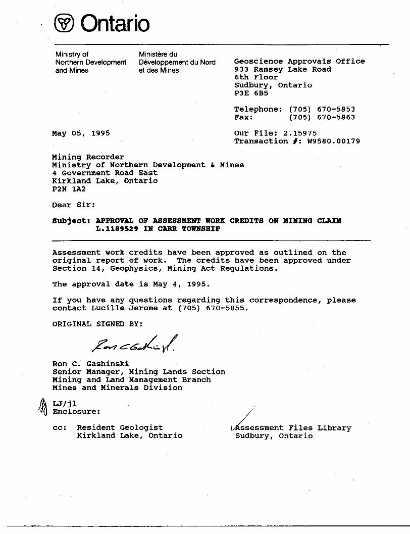
May 05, 1995
Geoscience Approvals Office 933 Ramsey Lake Road 6th Floor Sudbury, Ontario P3E 6B5
Telephone: (705) 670-5853 Fax: (705) 670-5863
Our File: 2.15975 Transaction #: W9580.00179
Mining RecorderMinistry of Northern Development St Mines4 Government Road EastKirkland Lake, OntarioP2N 1A2
Dear Sir:
Subject: APPROVAL OF ASSESSMENT WORK CREDITS ON MINING CLAIM L.1189529 IN CARR TOWNSHIP
Assessment work credits have been approved as outlined on the original report of work. The credits have been approved under Section 14, Geophysics, Mining Act Regulations.
The approval date is May 4, 1995.
If you have any questions regarding this correspondence, please contact Lucille Jerome at (705) 670-5855.
ORIGINAL SIGNED BY:
*S^^. yf.
Ron C. GashinskiSenior Manager, Mining Lands Section Mining and Land Management Branch Mines and Minerals Division
LJ/jl Enclosure:
cc: Resident GeologistKirkland Lake, Ontario
Assessment Files Library Sudbury, Ontario
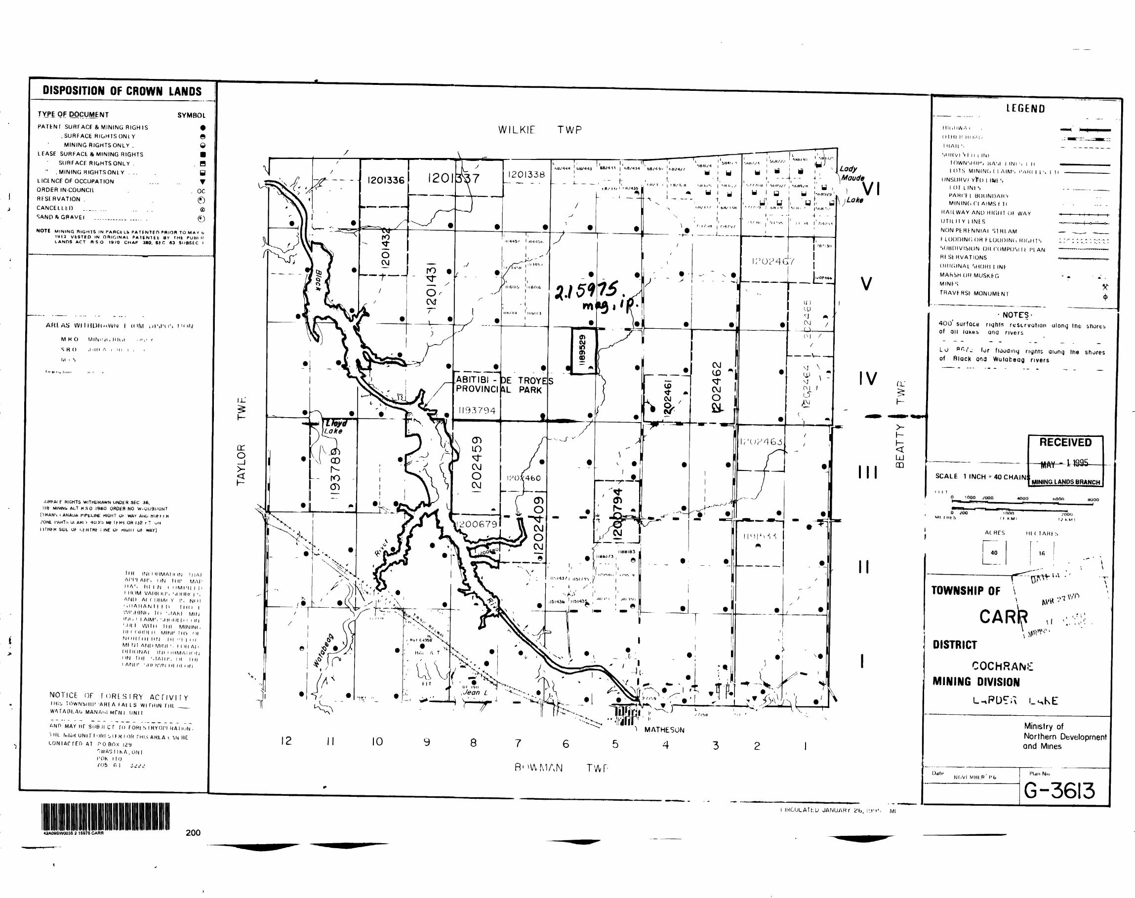
DISPOSITION OF CROWN LANDS
QF DOCUMENTPATENT SURFACE ft MINING RIGHIS
.SURFACE RIGHTS ONt Y MINING RIGHTSONLY .
LEASE SURFACfc Si MINING RIGHTSSURFACE RICiHTSONLY .
" , MINING RIGHTSONLY . -- LICINCE OF OCCUPATION ORDER IN-COUNCIl RESERVATION . CANCELLtH ...,. ...
SYMBOL
gm m B T
OC
NOTE MINING RIGHTS IN PARCtUb PATENTEn PRIOR TO MAY b 1913 VfcSTED IN ORIGINAL PAIfNltfc BY THfc PUHI If LANDS ACT R SO 19/0 CHAP 380, St C *3 Sl/BStC l
AFUAS W IIHl)K'*Wlvl l UWI i/ISI'u'. l "'N
MHO MINnji, Illiif ' "- 1 t
S H O .l 'Ki A i m i ,
I'vl i S
i..*.., i.,...
( f M IGHTS WlTHDHAWN UNDtR SEC 36, lilt WININO ACT HSO 1980 ORDER NO W-OI/9I/ONT
(THAN'i iANAUA riPtUNC NIGHT Ul- WAV ANU HUH-1-K /ONt I'AHTli Ul AKIV 10 2D Mt 11 KS OR 142 r T UN
SlUt. Op i.tNTRt l INE OK mull l Of WAY)
1IU INt l HIMAI II IN M IAI Al'l'l AH 1 , l )N IHI 1 MAI 1 11 A ', H l l H i i i M l' 11 l l i l MOM VAHIOU', M )IIH( l ',AND A( ( iiMAi Y r. NOI' .IIAHAN I l l H l IK ) l WI'.MINli K) ',IAKI MlfJ INI , ( l AIM'. Mil 'III h r ( irj Mil l WITH Till MININ(. HI i (iMHI II MINI' HO 'H N f) 11 l H l H r J l 11 '' l l ' ' l Ml Nl AND MINI ', l ( l|( Al i DI l IONAI INI i iHMAI |( ifj ON IHI '.TAIII', ()l IHI l AND' '.Hi )WN HI Ml i )rj
NOTICE OF FORLSIRY ACflVIfYl Mli, TOWNSllir 'A H E A FAI L S W l THIN ft) L ^.^ WATA11LAL, MANAi.l MfN l DNII
ANH MAY nr SUB Ji c r ro fonts IRYOPI KA i ION'i ML N,|Jrt UNI riOM jIFK l Of* THLS AKtA i \N HC
AT P O BOX l2y".WAS l IK A, UN lroK iruf05 f. l ± ,1,!±
WILKIE TWP
Maude
\ }Lato
lU ^
oro—i
PROVINCmL PARK
193794
VI
R-WIMAN
V
IV
II
II
QJ
LU OD
( IKCULAThU JANUARf k'b, I'J'i', Ml
LEGEND
DlHt l! Id I'M -
l HAIL '.
MIMVt V l l) l INITOWNSHIPS HAM l INI '. l Kl OTS MlNINd ( l AIMS I'AKI l l S l K
UNSUHW Y^U l IWtSl OT LINtSPAKCF l UOUNDAHVWININd CI AIMS f K
RAILWAY AND HIHHt Oh WAY UTILI1 Y l INtS
NON PfcHtNNIAI S1HLAM f LOOniNf, OH FLOODING RK.HTS ', SUBIIIVISIUN OH rOMPOSl It IHAN RfStHVATIONS OHKilNAL SHOHl l INF MARSH OH MUSK.FG MINFS
THAVFRSt MONUMENT
H———t-
- NOTES-400' surface rights reservation along (ne shores of ail lakes and rivers
Lo P*V^ for flooding rignts along (he shores of BlQcK and Watabeag rivers
SCALE 1 INCH -40 CHAIN
RECEIVED
miMINING LANDS BRANCH
i t io i ooo .'ooa 4OOO HOOD
ol Ut S
?oool 3 K. H \
AC HFS
L4:HI ( TAHt S
ir,
u\ - '
TOWNSHIP OF \y
CAR|RDISTRICT
COCHRANE MINING DIVISION
Ministry ofNorthern Developmentand Mines
N(JVI MHhR
G-3613
42AQSSWQ036 2 16076 CARR 200
l l
4
iL-
if\N)OCJ
nr fL J ! V J
UTUJo0
un4^.Oo
cn- o
m
f ' If
l f-
L L
42A09SW0035 2 15975 CARR 210
4 .
/'.1.;!-" t '-i f
.W 4 1 A?
?TKT}f " RJ-S f:PROFEKTV
" ^ ** ' Ti 'v- i '-r. f;'"!"1 "
K v t
InUro J.C.^ian* '"b
oRI
LINE 5200 E
[NDUCED POLflRIZRTION SURVEY
DIPOLE:-
DEPTH'POINT N r l, 2. 3. 4, .
"R" SPflCINB - 50 O METRES
IN
S
.P E NJ[j- ̂ D^JJTH VENTURESCRRR PROJECTCRRR TOWNSHIP
F :DRTE : 5/11/94 RE
SCflLE - I : 5000
EXSICS EXPLQRRTION LTD
H? CHO.
———————— . H? CHJ.s -T
O -H
m -T
D H
-S —l -IDD —t—i——(——i——t——i——411QOK 11 COM 110DN 1HON ItDOM lliDN J4QQN I*(DN
Nil
NlS
NiS
H li
MIS
H.6
-' - 1 - J- ' 2 l-' l-i 411 .4 H ll
RESISTIVITYNil
Nit
NiiHI*NlS
REBlSTJVITr 60.E 9S.9 61 O S7.D 3.S 5S.O SS t 54.1 Nil
.*_M 7 w.* ae.* M Tira.7 isi.i us.s )2E.g )is 7 ir.s 107IY~sD*.* \
till O US-O H7.Q tCD O
110.0 111 D JflB.O 1BJ.O 1*3.D 1^-0
JBD.O (93.0
Hit
Ni3
NI9
O CO
LINE : 5400 E
INDUCED PDRECEIVED
,RRIZRTION^UBj/EUfAY-11995
MINING LANDS BRANCHDIPOLE-DIPOLE RRRRY
\ f
DtrTH'fOlKT N 3 1. Z. 3. 4.
•fi" SPflCINP * 50-0 METRES
PENTLRND FIRTH VENTURES
CRRR PROJECT
CRRR TOWNSHIP ( tji DRTE : 17/10/94 RE*
SCRLE r 1: 5000
EXSICS EXPLORRTION LTD
-i —i
o H
-fOO —l——i——l——i——l——t——H -4-IIOQ* ]|RM ItBDN IBEtM JIOCM lHiON )4aqn
p- an
f— o
-aoo
R?r— j
— O
— -l
M? CHO.Ml]
Nit
MIS
M tt
NtS
me
.S 5 . 9 . J
.| Q •"o" e.o .( ^x^Tl l-r 4 l- s -' -e '
-.1 \ .t S^l O f 1.7 .4 7 -.J H .S
J j .T y - 9 - J.I -^ V*O 1 -S ''* l ft.9 .1 /I.* -L* -l-l I t-t'/'iQ I .I l-f
N7 CHO• t N il
M ir maMM
K 13
31
REStlTlVm
?44-9 rsi 5 tin.B"~~ra!n^ in.D 110.9
REBJSTJVITr S52 SI l SI.? Nil
NO
MM
Mil
Hie
INDUCED POLARI SURVEY*
ION
LANDS
DEfTHP01IITN s 1. Z. 3. 4. .- .
fi" SmCINfr * 50- Q METRES
Os
TLRND FIRTH VENTURES
CflRR PROJECT
CRRR TOWNSHIPDflTE s 17/10/94 RE
/ 'P t
SCflLE r I: 5000EXSICS EXPLORRTION LTD
H? CHO.
RT KtS t —i 4Bb -T
___., , H? D*.o?
a —
-t — l
o —
MBON KBDN 1CSOH )|OCM IKON 140QH 1 1 KM l la DM-400 ' — -t
miHit
NiS
H14
NIB
• •6
LI 7 -B 3 B .1 .8
.1 1.0 .B .B 1.0 .S
1.4 l-S 1.5 1.4 16 jf6~*\ - S
l fB .? -l 4
-T ̂ *-a -e •S .f
r . ^a o , , ^TT o .1 j iv-_^J l ~\ ^_^
-.i .7 .s -.4 -i.i \ iA ~
W C HO .t N il
Nit
• 14
d IS
Mie
REBisnvnr41 t SB-9 Nil
Nlf
M.4no