health & safety executive - complete pictureregulations.completepicture.co.uk/pdf/health and...
TRANSCRIPT
Guidance Note GS 51from the
HSE Health and SafetyHealth & Safety
Executive Executive
Facade retention
General Series 51 (January 1992)
These Guidance Notes are published under five subjectheadings: Medical, Environmental Hygiene, ChemicalSafety, Plant and Machinery and General,
INTRODUCTION
1 In urban areas a site is often redeveloped, but inorder to preserve the historical appearance of itsbuilding, planning or conservation policy may requirethat the existing facade is retained and the new structureinserted behind it. This facade retention may apply toone or more faces of a building. The facade is madestable by connecting it to the new structure, which maybe of steel or concrete framing or masonry cross walls.
2 By the publication of this Guidance Note theHealth and Safety Executive is not advocating that oldbuildings should be preserved by retaining their facadesonly. That decision must be made by those responsiblefor the building based on conservation views, planningrequirements, structural considerations and aesthetics.Nevertheless, once a decision has been made topreserve the facade alone, it is necessary that the wholeof the building be evaluated, for example in terraceddomestic buildings where work carried out on one partmay have an effect on the method of work for the wholestructure as well as on its stability.
3 It is expected that the design of any facaderetention system will be carried out by a chartered civil orstructural engineer who is experienced in and has anunderstanding of the type of work being undertaken.This Guidance Note is not intended to be a design guide.It is intended to highlight relevant matters of health andsafety for engineers and inspectors regarding the use offacade retention systems. For guidance on demolitionsee Guidance Note GS 29/1 -4 (Ref 1).
4 It is recommended that contact is made with thelocal authority, police and services suppliers before anyscheme is finalised. A paper addressing this matter waspublished by the Institution of Structural Engineers(Ref 2).
5 Buildings normally requiring this type of work arethose originally built in the eighteenth or nineteenthcenturies, from three to eight storeys in height and stonefaced. Windows will be arranged in fairly regular patternand may form a large proportion of the facade area. Mostbuildings will be of load bearing masonry construction.
6 During the demolition and new construction phasesthe facade needs to be held in its original position so thatit can resist the vibration and movement of constructionactivities, traffic and the loading from wind and weather.In order to do this various systems are used includingvertical or raking shores, horizontal wind girders andkentledge. Whatever system is erected, it must be strongenough to carry the loads and stiff enough to hold theexisting wall in a secure manner with minimal deflectionswhile the new work is completed. The use, temporarily orotherwise, of original rubble-filled walls will determine thetype of bearing necessary for concentrated loads to beadequately spread and supported. It will also benecessary when carrying out any fixing, supporting orbracing work that care is taken to avoid causing anydamage to the facade.
ANCILLARY WORK
7 Some urban sites may have limited space for theprovision of site accommodation and storage ofmaterials. The positioning of these will need to beallowed for at the planning stage.
8 A very specialised form of shoring which is usedwhen a whole building is to be jacked up and movedbodily on prepared slides is not considered in thisGuidance Note.
GENERAL STRUCTURAL CONSIDERATIONS
9 Most of the buildings which require facades to beretained are of load bearing construction with timberfloorboards supported on timber joists. The walls arelikely to be reasonably thick but not necessarily of solidconstruction. Often the walls are constructed from astone facing attached to a brick backing or two leaves ofstonework with rubble infill. Other types of constructionare also used. The walls may contain timber lintels orbonding timbers and pocket seatings for joists. Thelayout and detail of the new construction and theretained original facade will determine the layout andtype of temporary works and the method of constructionto be followed. As part of the new building work it maybe necessary to remove internal crosswalks which mayeither be of masonry or timber stud construction. If anycrosswalks or floors are to be retained, suitable tiesshould be designed and installed appropriately.
1
10 Before any major work commences, it will benecessary for a structural survey to be carried out todetermine the layout, construction and condition of theexisting building. The survey will also determine howstructural stability is being achieved. Structural design ofthe new building should ensure that the building can beconstructed safely with particular consideration given tohow stability of retained parts of the existing building canbe achieved during demolition and reconstruction.
11 The site layout and surrounding road andpavement pattern including cellars, pavement lights,services and basements will to some extent determinethe spread of the base of the shores. In general, thegreater the spread of the base of the shores the lower theloads in the structure and the foundations. In some casesthe type of road adjacent to the site or the surroundingservices and their access may limit the system to the useof a pavement frame only with no encroachment into theroad at all. In other cases road closures may benecessary to accommodate the chosen system.Whatever the layout, the temporary frames will need tobe protected from damage from vehicle impact. Theprovision of timber kerbs, barriers and lighting will benecessary to conform with local authority requirements.
12 The normal street gutter and gully drainage maywell be interrupted by the shoring structure andfoundations. Consideration should be given to providingtemporary drainage, eg by the provision of pipes cast intothe foundation blocks to allow the water to drain away.
13 Old walls properly braced by crosswalks and floorsmay have stood satisfactorily for many years on whatmay now be regarded as poor or undersizedfoundations. Even though the load on the facade wall willbe reduced, a check may be required to determine theload carrying capacity of the existing foundations and asite investigation may need to be carried out. It may benecessary to carry out remedial work or underpinning tothe existing construction before other work can proceed.In buildings with cellars or basements substantiallybelow surrounding ground level, removal of the groundfloor and internal walls will probably necessitateprovision of internal raking or flying shores to prop thebasement walls as part of the demolition work.
14 The existing windows will generally be removedand the resulting holes may need to be braced ortemporarily filled. Temporary vertical props or bricking upof thinner areas of walls or chases may also be requiredso as to maintain the integrity of the wall in its temporarycondition. An investigation of chimney flues should becarried out and any similar making good or fillingdecided upon. Many old buildings have chimney flues inthe thickness of the facade wall. However, the presenceand location of these may be difficult to detect due toinstallation of central heating and subsequent removaland sealing of fireplaces and capping of external flueopenings. Buildings with basements sometimesincorporate ventilation ducts in the facade walls.Location and making good or filling of these flues/ductsis best carried out when the original floors are availablefor access and before internal demolition commences
15 Any unexpected voids in the masonry or othermatters not in accordance with the drawings foundduring subsequent construction works should beimmediately reported to the designer of the shoring andthe structural designer of the new building in case theyadversely affect the integrity of the facade. It may benecessary for voids in rubble-hearted walls to be groutedsolid and this should be carried out by a specialist. Thefilling of joist and lintel pockets may also need to bemade good. Any necessary foundation work will need tobe carried out before the major work begins.
SHORING
16 Once the self-weight can be assumed to besuitably supported, the greatest load to be carried by theshoring system is that caused by the wind. In the designof the system the intensity of wind load, the size of thefacade holes and the load factoring should take accountof the likely life of the system. The loads and load factorsmust be appropriate to the anticipated length of time theshoring system is expected to be in use. Generally thedesign load will be the appropriate wind load plus 2.5 1oof the dead load of the facade. The method ofconnecting the shoring to the facade wall must suit theconstruction of the wall.
17 It must be realised that during the demolition phaseand other interim phases of the work, wind loads may beincreased or differ from those taken by the originalbuilding. This variation may be due to walls which mayhave been sheltered originally or the funnel effect due tothe removal of existing walls. Design heights of walls maybe increased due to the removal of floors.
18 The design of the temporary shoring system willbe dependent on the position and number of walls to beretained, the layout of the existing building and theposition and number of new floors. It is essential that anyinternal shoring can be erected easily within the confinesof the original building so that demolition can be carriedout safely and that the new structure can be erected orbuilt clear of the temporary shoring work. Guidance NoteGS 28/1-4 may prove useful (Ref 3). The installation ofthe shoring and removal of structural walls/floors mustbe carried out in a predetermined sequence to ensurethat the integrity of the structure is maintainedthroughout the demolition phase. Similarly, any removalof internal shoring should be phased in with completionof the new internal structure and its bonding to thefacade. Finally, when the new building and existingfacade have been connected together structurally, thetemporary shoring can be removed safely.
Wind girders and flying shores
19 The use of horizontal wind girders or flying shoresis dependent on there being adequate existing returnwalls or other means to carry the loads down to groundlevel support which may be road or basement level. Theuse of wind girders may ease the temporary structuraldesign, but their use may impede the carrying out of thenew construction work.
2
Vertical raking shores
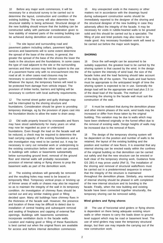
20 If wind girders or flying shores cannot be used, thevertical raking shores must be designed as cantileverframes to carry the worst combination of loads imposedon them and particularly the wind loads in both directions(Figure 1). The shores may have to be designed to resistboth compression and tension in the members and jointsand the foundations to be capable of resistingcompression and uplift with a sufficient mass ofconcrete, kentledge or other means used to resist anyupward load. Foundation bolts will need to resist theshear and uplift forces. Deflections must be limited topreserve the integrity of the retained structure.
Shoring methods used
21 Vertical shores may be made from conventionalscaffold tube and fittings or bridging trestles. Windowsand other openings can be braced, the scaffolding ortimber dependent on the size of the opening involved.
22 The construction of wind girders and shores canbe found using scaffold tube, structural steel or
proprietary systems (Figures 2 to 5) or any combinationof these. Scaffold tube has the advantage that it can beused and adapted to suit the conditions found on site.Because there is a limitation on the load carrying valueof tubes and couplers it may be necessary to usemultiple members. In this case the use of scaffold tubemay become unwieldy in larger shoring systems. Onedisadvantage is the multiplicity of joints.
23 Structural steel sections for shoring or frames canbe chosen to suit the loads involved but surveys must bemade prior to fabrication and allowances made forwedging and tying the existing structure. Decisions as towhat system or combination to use will usually be madeby the contractor’s designer on a basis of safety, cost,site conditions and suitability for the method to be usedand the type of construction.
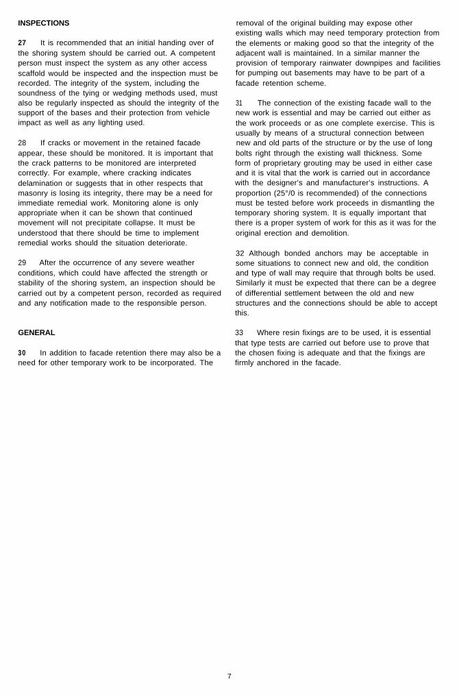
24 One recent system has used a reinforced concreteservices tower to afford stability for the facade walls afterdemolition of the original internal structure. The tower isused to support the horizontal struts and ties, providingsupport to the external facade walls (Figure 6).
Figure 1 Proprietary system side frames. Note the use of horizontal wind girders connected to the side frames.
3
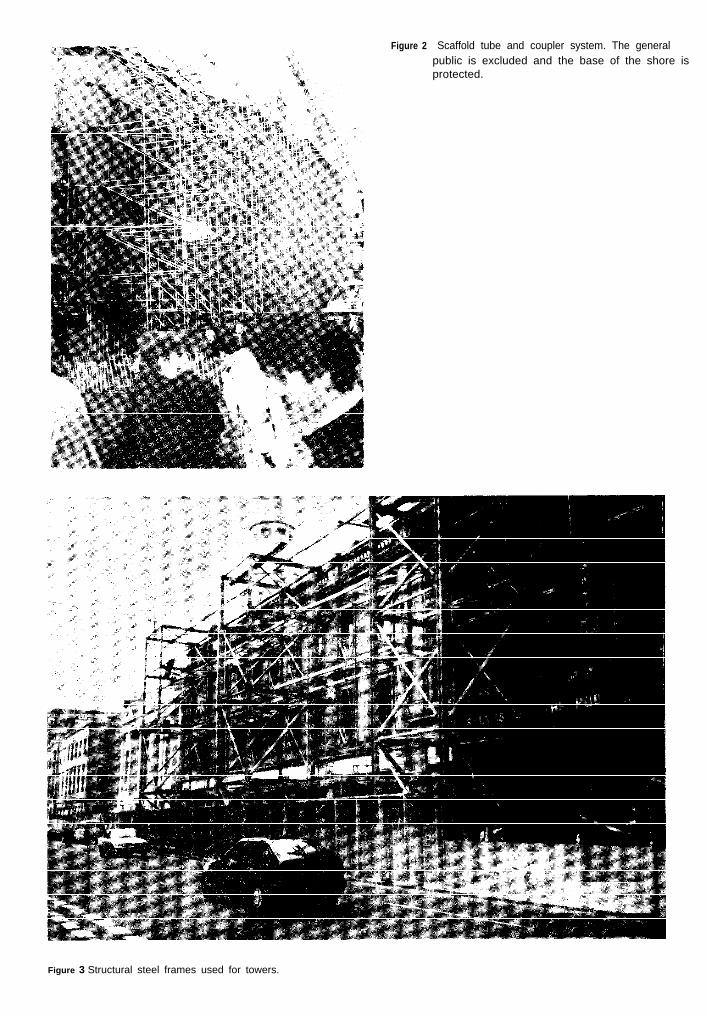
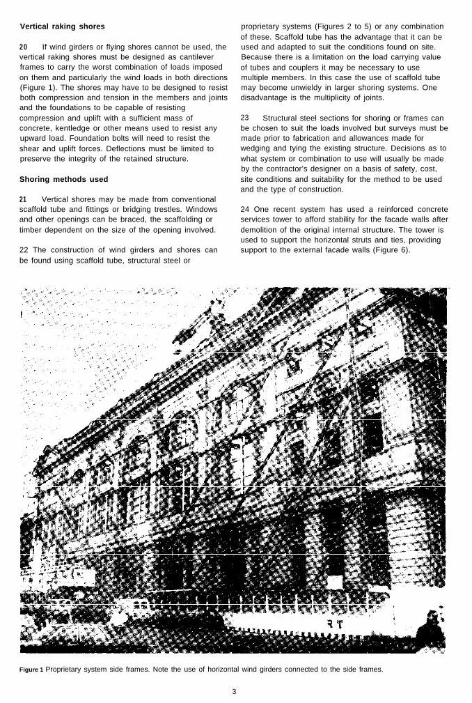
Figure 2 Scaffold tube and coupler system. The generalpublic is excluded and the base of the shore is protected.
Figure 3 Structural steel frames used for towers.
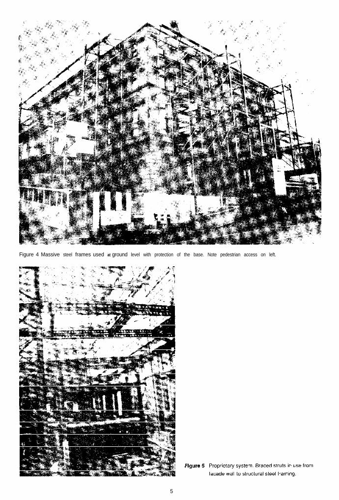
Figure 4 Massive steel frames used at ground level with protection of the base. Note pedestrian access on left.
5
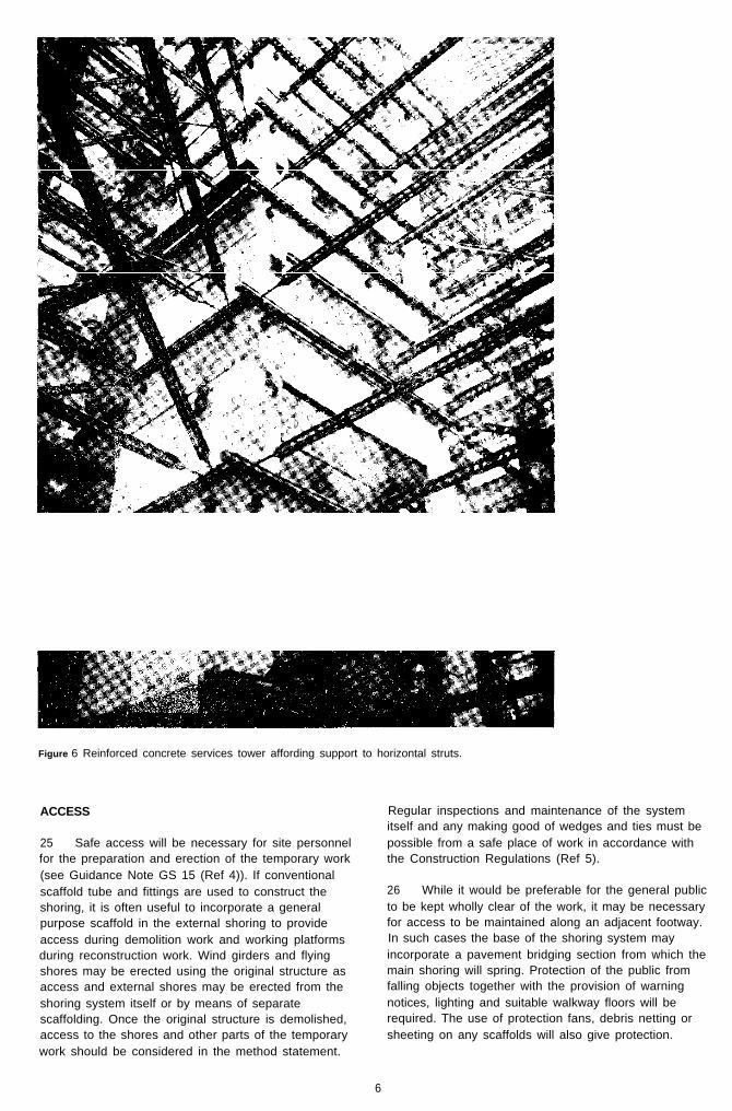
Figure 6 Reinforced concrete services tower affording support to horizontal struts.
ACCESS
25 Safe access will be necessary for site personnelfor the preparation and erection of the temporary work(see Guidance Note GS 15 (Ref 4)). If conventionalscaffold tube and fittings are used to construct theshoring, it is often useful to incorporate a generalpurpose scaffold in the external shoring to provideaccess during demolition work and working platformsduring reconstruction work. Wind girders and flyingshores may be erected using the original structure asaccess and external shores may be erected from theshoring system itself or by means of separatescaffolding. Once the original structure is demolished,access to the shores and other parts of the temporarywork should be considered in the method statement.
Regular inspections and maintenance of the systemitself and any making good of wedges and ties must bepossible from a safe place of work in accordance withthe Construction Regulations (Ref 5).
26 While it would be preferable for the general publicto be kept wholly clear of the work, it may be necessaryfor access to be maintained along an adjacent footway.In such cases the base of the shoring system mayincorporate a pavement bridging section from which themain shoring will spring. Protection of the public fromfalling objects together with the provision of warningnotices, lighting and suitable walkway floors will berequired. The use of protection fans, debris netting orsheeting on any scaffolds will also give protection.
6
INSPECTIONS
27 It is recommended that an initial handing over ofthe shoring system should be carried out. A competentperson must inspect the system as any other accessscaffold would be inspected and the inspection must berecorded. The integrity of the system, including thesoundness of the tying or wedging methods used, mustalso be regularly inspected as should the integrity of thesupport of the bases and their protection from vehicleimpact as well as any lighting used.
28 If cracks or movement in the retained facadeappear, these should be monitored. It is important thatthe crack patterns to be monitored are interpretedcorrectly. For example, where cracking indicatesdelamination or suggests that in other respects thatmasonry is losing its integrity, there may be a need forimmediate remedial work. Monitoring alone is onlyappropriate when it can be shown that continuedmovement will not precipitate collapse. It must beunderstood that there should be time to implement
‘. remedial works should the situation deteriorate.
29 After the occurrence of any severe weatherconditions, which could have affected the strength orstability of the shoring system, an inspection should becarried out by a competent person, recorded as requiredand any notification made to the responsible person.
GENERAL
30 In addition to facade retentionneed for other temporary work to be
there may also be aincorporated. The
removal of the original building may expose otherexisting walls which may need temporary protection fromthe elements or making good so that the integrity of theadjacent wall is maintained. In a similar manner theprovision of temporary rainwater downpipes and facilitiesfor pumping out basements may have to be part of afacade retention scheme.
31 The connection of the existing facade wall to thenew work is essential and may be carried out either asthe work proceeds or as one complete exercise. This isusually by means of a structural connection betweennew and old parts of the structure or by the use of longbolts right through the existing wall thickness. Someform of proprietary grouting may be used in either caseand it is vital that the work is carried out in accordancewith the designer’s and manufacturer’s instructions. Aproportion (25°/0 is recommended) of the connectionsmust be tested before work proceeds in dismantling thetemporary shoring system. It is equally important thatthere is a proper system of work for this as it was for theoriginal erection and demolition.
32 Although bonded anchors may be acceptable insome situations to connect new and old, the conditionand type of wall may require that through bolts be used.Similarly it must be expected that there can be a degreeof differential settlement between the old and newstructures and the connections should be able to acceptthis.
33 Where resin fixings are to be used, it is essentialthat type tests are carried out before use to prove thatthe chosen fixing is adequate and that the fixings arefirmly anchored in the facade.
7
REFERENCES
1 Guidance Note GS 29 Health and safety indemolition workPart 1: preparation and planningHMSO ISBN O 118854054Part 2: /legislation HMSO ISBN O 118835890Part 3: techniques HMSO ISBN O 118836099Part 4: hea/th hazards HMSO ISBN O 118836048
2 Goodchild S and Kaminski M P ‘Retention of majorfacades’ The Structural Engineer April 1989,VOI 67, no 8, pp 131-8
3 Guidance Note GS 28 Safe erection of structuresPart 1: initial planning and designHMSO ISBN O 11 883584XPart 2: site management and proceduresHMSO ISBN O 118836056Part 3: working places and accessHMSO ISBN O 118835300Part 4: legislation and trainingHMSO ISBN O 118835319
4 Guidance Note GS 15 Genera/ access scaffoldsHMSO ISBN O 118835459
5 Construction (General Provisions) Regulations1961 S1 1961/1580 HMSO ISBN O 11 1001439and Construction (Working Places) RegulationsS1 1966/94 HMSO ISBN O 11 1002648
ISBN O–ll -885727-4
This publication is no longer available from HMSO
Published by HSE Books I I I I9 7 8 0 1 1 8 8 5 7 2 7 7
Printed m the UK for HSE, publlshed by HMSO
8