heavy ion test report for the msk5965rh low … · heavy ion test report for the msk5965rh low...
TRANSCRIPT
Heavy Ion Test Report for the MSK5965RH
Low Dropout Voltage Regulator with the
RH1965 Die
Test conducted by: Shirley Hart1, Paul Musil2, David Beebe3, and
Bryan Horton2
Report prepared by: Dakai Chen3
1. Previously Linear Technology Corp., now Jet Propulsion Laboratory, Pasadena, CA 91109
2. Anaren Inc. / MSK Products, E Syracuse NY 13057
3. Analog Devices Corp., Milpitas, CA 95035
Test Date: 02/17/17
Report Date: 6/1/2017

I. Introduction
The purpose of this test is to determine the heavy ion-induced single-event effect
(SEE) susceptibility for the MSK5965RH low dropout voltage regulator from Anaren /
MSK Products, which contains the RH1965MK die from Linear Technology
Corporation, now Analog Devices Corporation.
II. Device Under Test
The MSK5965RH is a low dropout linear regulator, featuring an adjustable output
voltage range of 1.2 V to 19.5 V [1]. The dropout voltage is typically 250mV with a 0.5A
load. The MSK5965RH is manufactured with the RH1965 die from Analog Devices [2].
The RH1965 is built on a proprietary Radhard process and qualified for total-ionizing
dose (TID) per Mil-Std-883 TM 1019 [3]. The MSK5965RH is packaged in a
hermetically sealed 10 pin Flatpack.
Figure 1 shows a schematic diagram of the device pinout with descriptions of each
pin. Table I lists the basic part and test information.
Figure 1. Schematic diagram of the pin configuration for the MSK5965RH.
Table I
Part and test information.
Parameter Description
Part Number: MSK5965RH
Manufacturer: Anaren / MSK Products
Die: RH1965MK
Die Manufacturer: Analog Devices
Lot Date Code (LDC): 1633
Die lot/wafer number: HP202273.2
Wafer #3
Quantity Tested: 2
Device Serial Number: 0058, 0059
Board Serial Number: 0079, 0083
Part Function: Low dropout voltage regulator

Part Technology: Bipolar
Package Style: Flatpack
Test Equipment: Voltage supply, oscilloscope, and PC
III. Test Facility
The heavy-ion beam testing was carried out at the Lawrence Berkeley National
Laboratory (LBNL) Berkeley Accelerator Space Effects (BASE) Facility. The facility
utilizes an 88-inch cyclotron to accelerate a cocktail of ions. The testing was performed
in vacuum.
Facility: Lawrence Berkeley National Laboratory
Cocktail: 10 MeV/amu
Flux: 1 × 10³ to 1 × 10⁵ ions/cm2/sec
Fluence: 1 × 10⁵ to 1 × 10⁷ ions/cm2 per run
Ions: Shown in Table II
Table II
Heavy-ion specie, linear energy transfer (LET) value, range, and energy.
Ion Initial LET in air
(MeV·cm2/mg)
Range in Si
(µm)
Energy
(MeV)
Ne 3.5 175 216
Ar 9.7 130 400
Cu 21.2 108 659
Kr 30.9 110 886
Xe 58.8 90 1232
IV. Test Method
A. Test Setup
We used a custom-built evaluation board for the heavy ion beam experiment. Figure 2
shows a schematic block diagram of the test circuit. Each device-under-test (DUT) was
delidded to expose the die surface.
A power supply and an oscilloscope were located in the beam chamber. We
controlled the oscilloscope directly from the control room via USB cables and extensions.
The oscilloscope output trigger levels were adjusted during the experiment to levels
slightly above the noise floor at the facility. The majority of the test was carried out with
a trigger of ±40 mV, and some runs had a trigger of ±100 mV. The oscilloscope SET
capture frequency was greater than approximately 1 kHz. The ion flux was maintained at
a level where the oscilloscope could capture and download the majority of the occurring
SETs.

Figure 2. Schematic diagram of the test circuit.
B. Test Conditions
Test Temperature: Ambient temperature (testing performed in vacuum)
Input Voltage: Vin = 4.5 to 16.5 V
Output Voltage: Vout = 1.5 and 3.3 V
Load: Iout = 0.14 to 0.7 A
Angles of Incidence: 0o (normal) and 45o
Parameters: Output voltage, input voltage
Beam time: Approximately 3 hours

V. Results
We found that the part was susceptible to single-event transient (SET) under the
evaluated test conditions. No destructive SEE was observed up to an effective LET of
83.2 MeV·cm2/mg. Figure 3 shows the SET cross section as a function of LET for
various device input and output conditions. The data were captured with an oscilloscope
trigger level of ±40 mV for the 1.5 V output and ±100 mV for the 3.3 V output.
The SET sensitivity varied depending on the bias conditions. The part was more
sensitive to SETs at lower input voltages. In Figure 3, we show the SET cross sections for
a 16.5 V input and averaged cross sections for a range of input voltages from 4.5 to 9.3
V. The figure shows that the LET threshold for the 16.5 V input is greater than 3.5
MeV·cm2/mg and less than or equal to 9.7 MeV·cm2/mg, while the LET threshold for the
lower input voltages is less than or equal to 3.5 MeV·cm2/mg.
The cross sections at LETs of 58.8 and 83.2 MeV·cm2/mg are lower than that at
lower LETs (21.2 and 30.9 MeV·cm2/mg), partly due to the higher trigger levels used for
those irradiations. So, the smaller transients (between ±40 and ±100 mV) were not
counted at those high LETs. Additionally, the device was more sensitive to SETs at the
higher LETs. So the transients occurred more frequently and in quicker successions
relative to the lower LETs. As a result, more transients were missed and not counted at
those LETs (58.8 and 83.2 MeV·cm2/mg), for the given oscilloscope capture settings.
The error bars represent Poisson error. The error bars are smaller than the data symbols
for cases where they are not visible. The data represent averaged values from two tested
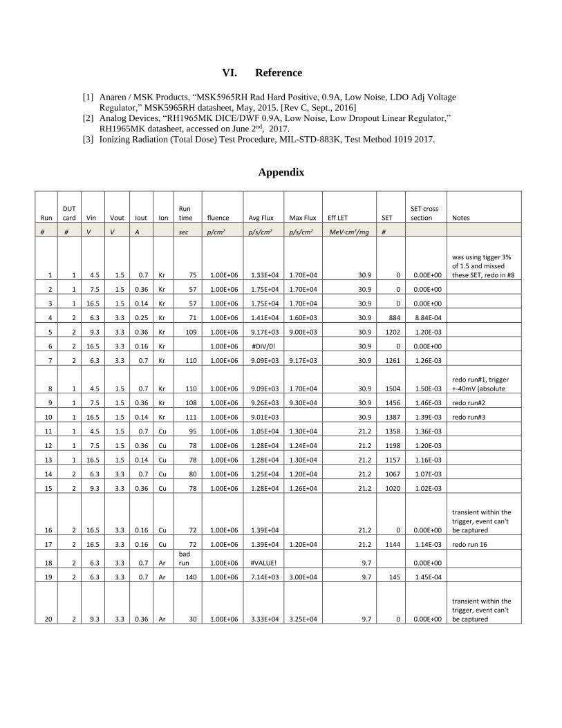
samples. The appendix shows the run logs.
Figure 3. SET cross section as a function of LET for the MSK5965RH irradiated with 10 MeV/nuc heavy
ions in vacuum.
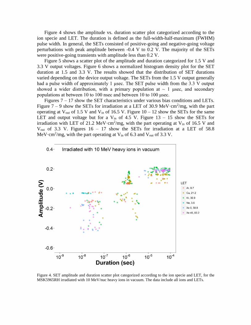
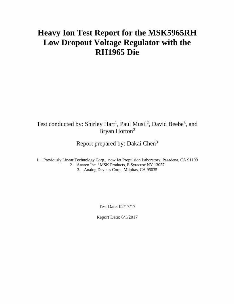
Figure 4 shows the amplitude vs. duration scatter plot categorized according to the
ion specie and LET. The duration is defined as the full-width-half-maximum (FWHM)
pulse width. In general, the SETs consisted of positive-going and negative-going voltage
perturbations with peak amplitude between -0.4 V to 0.2 V. The majority of the SETs
were positive-going transients with amplitude less than 0.2 V.
Figure 5 shows a scatter plot of the amplitude and duration categorized for 1.5 V and
3.3 V output voltages. Figure 6 shows a normalized histogram density plot for the SET
duration at 1.5 and 3.3 V. The results showed that the distribution of SET durations
varied depending on the device output voltage. The SETs from the 1.5 V output generally
had a pulse width of approximately 1 μsec. The SET pulse width from the 3.3 V output
showed a wider distribution, with a primary population at ~ 1 μsec, and secondary
populations at between 10 to 100 nsec and between 10 to 100 μsec.
Figures 7 – 17 show the SET characteristics under various bias conditions and LETs.
Figure 7 – 9 show the SETs for irradiation at a LET of 30.9 MeV·cm2/mg, with the part
operating at Vout of 1.5 V and Vin of 16.5 V. Figure 10 – 12 show the SETs for the same
LET and output voltage but for a Vin of 4.5 V. Figure 13 – 15 show the SETs for
irradiation with LET of 21.2 MeV·cm2/mg, with the part operating at Vin of 16.5 V and
Vout of 3.3 V. Figures 16 – 17 show the SETs for irradiation at a LET of 58.8
MeV·cm2/mg, with the part operating at Vin of 6.3 and Vout of 3.3 V.
Figure 4. SET amplitude and duration scatter plot categorized according to the ion specie and LET, for the
MSK5965RH irradiated with 10 MeV/nuc heavy ions in vacuum. The data include all ions and LETs.

Figure 5. SET amplitude and duration scatter plot categorized according to the output voltage, for the
MSK5965RH irradiated with 10 MeV/nuc heavy ions in vacuum. The data include all ions and LETs.
Figure 6. Normalized density histogram of SET durations categorized according to the output voltage, for
the MSK5965RH irradiated with 10 MeV/nuc heavy ions in vacuum. The data include all ions and LETs.

Figure 7. SET characteristics for the MSK5965RH irradiated with 10 MeV/nuc Kr ions at normal incidence
for a LET of 30.9 MeV·cm2/mg, with Vin = 16.5 V, Vout = 1.5 V, and Iout = 0.14 A.
Figure 8. SET characteristics for the MSK5965RH irradiated with 10 MeV/nuc Kr ions at normal incidence
for a LET of 30.9 MeV·cm2/mg, with Vin = 16.5 V, Vout = 1.5 V, and Iout = 0.14 A.

Figure 9. SET characteristics for the MSK5965RH irradiated with 10 MeV/nuc Kr ions at normal incidence
for a LET of 30.9 MeV·cm2/mg, with Vin = 16.5 V, Vout = 1.5 V, and Iout = 0.14 A.
Figure 10. SET characteristics for the MSK5965RH irradiated with 10 MeV/nuc Kr ions at normal
incidence for a LET of 30.9 MeV·cm2/mg, with Vin = 4.5 V, Vout = 1.5 V, and Iout = 0.7 A.
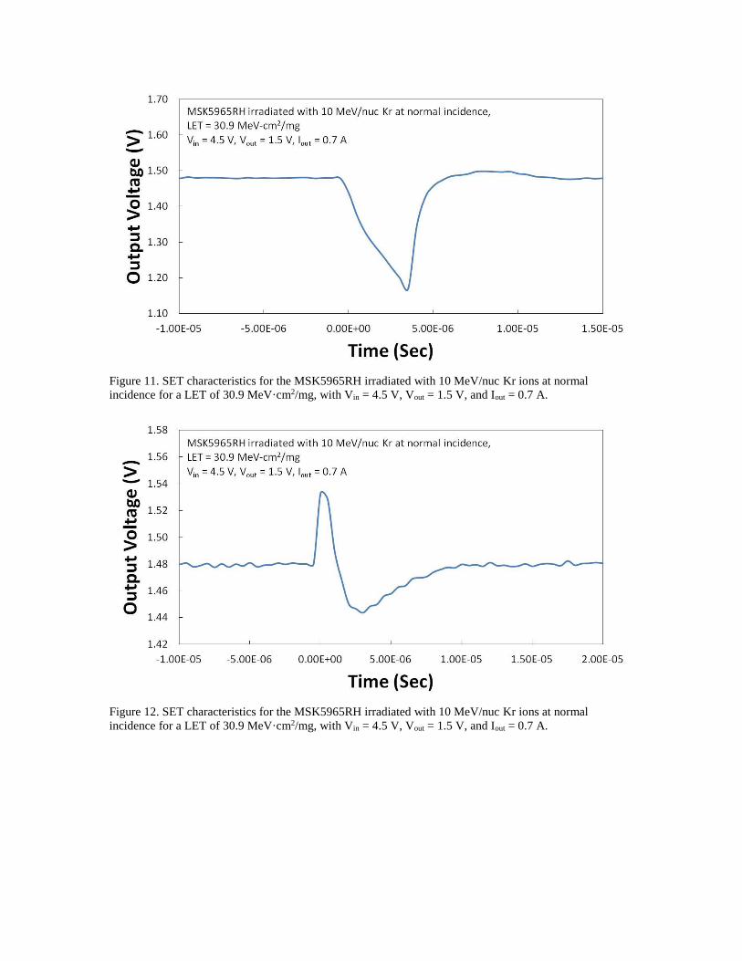
Figure 11. SET characteristics for the MSK5965RH irradiated with 10 MeV/nuc Kr ions at normal
incidence for a LET of 30.9 MeV·cm2/mg, with Vin = 4.5 V, Vout = 1.5 V, and Iout = 0.7 A.
Figure 12. SET characteristics for the MSK5965RH irradiated with 10 MeV/nuc Kr ions at normal
incidence for a LET of 30.9 MeV·cm2/mg, with Vin = 4.5 V, Vout = 1.5 V, and Iout = 0.7 A.

Figure 13. SET characteristics for the MSK5965RH irradiated with 10 MeV/nuc Cu ions at normal
incidence for a LET of 21.2 MeV·cm2/mg, with Vin = 16.5 V, Vout = 3.3 V, and Iout = 0.14 A.
Figure 14. SET characteristics for the MSK5965RH irradiated with 10 MeV/nuc Cu ions at normal
incidence for a LET of 21.2 MeV·cm2/mg, with Vin = 16.5 V, Vout = 3.3 V, and Iout = 0.14 A.
Figure 15. SET characteristics for the MSK5965RH irradiated with 10 MeV/nuc Cu ions at normal
incidence for a LET of 21.2 MeV·cm2/mg, with Vin = 16.5 V, Vout = 3.3 V, and Iout = 0.14 A.
Figure 16. SET characteristics for the MSK5965RH irradiated with 10 MeV/nuc Xe ions at normal
incidence for a LET 58.8 MeV·cm2/mg, with Vin = 6.3 V, Vout = 3.3 V, and Iout = 0.7 A.

Figure 17. SET characteristics for the MSK5965RH irradiated with 10 MeV/nuc Xe ions at normal
incidence for a LET 58.8 MeV·cm2/mg, with Vin = 6.3 V, Vout = 3.3 V, and Iout = 0.7 A.
VI. Reference
[1] Anaren / MSK Products, “MSK5965RH Rad Hard Positive, 0.9A, Low Noise, LDO Adj Voltage
Regulator,” MSK5965RH datasheet, May, 2015. [Rev C, Sept., 2016]
[2] Analog Devices, “RH1965MK DICE/DWF 0.9A, Low Noise, Low Dropout Linear Regulator,”
RH1965MK datasheet, accessed on June 2nd, 2017.
[3] Ionizing Radiation (Total Dose) Test Procedure, MIL-STD-883K, Test Method 1019 2017.
Appendix
Run DUT card Vin Vout Iout Ion
Run time fluence Avg Flux Max Flux Eff LET SET
SET cross section Notes
# # V V A sec p/cm2 p/s/cm2 p/s/cm2 MeV·cm2/mg #
1 1 4.5 1.5 0.7 Kr 75 1.00E+06 1.33E+04 1.70E+04 30.9 0 0.00E+00
was using tigger 3% of 1.5 and missed these SET, redo in #8
2 1 7.5 1.5 0.36 Kr 57 1.00E+06 1.75E+04 1.70E+04 30.9 0 0.00E+00
3 1 16.5 1.5 0.14 Kr 57 1.00E+06 1.75E+04 1.70E+04 30.9 0 0.00E+00
4 2 6.3 3.3 0.25 Kr 71 1.00E+06 1.41E+04 1.60E+03 30.9 884 8.84E-04
5 2 9.3 3.3 0.36 Kr 109 1.00E+06 9.17E+03 9.00E+03 30.9 1202 1.20E-03
6 2 16.5 3.3 0.16 Kr
1.00E+06 #DIV/0!
30.9 0 0.00E+00
7 2 6.3 3.3 0.7 Kr 110 1.00E+06 9.09E+03 9.17E+03 30.9 1261 1.26E-03
8 1 4.5 1.5 0.7 Kr 110 1.00E+06 9.09E+03 1.70E+04 30.9 1504 1.50E-03 redo run#1, trigger +-40mV (absolute
9 1 7.5 1.5 0.36 Kr 108 1.00E+06 9.26E+03 9.30E+04 30.9 1456 1.46E-03 redo run#2
10 1 16.5 1.5 0.14 Kr 111 1.00E+06 9.01E+03
30.9 1387 1.39E-03 redo run#3
11 1 4.5 1.5 0.7 Cu 95 1.00E+06 1.05E+04 1.30E+04 21.2 1358 1.36E-03
12 1 7.5 1.5 0.36 Cu 78 1.00E+06 1.28E+04 1.24E+04 21.2 1198 1.20E-03
13 1 16.5 1.5 0.14 Cu 78 1.00E+06 1.28E+04 1.30E+04 21.2 1157 1.16E-03
14 2 6.3 3.3 0.7 Cu 80 1.00E+06 1.25E+04 1.20E+04 21.2 1067 1.07E-03
15 2 9.3 3.3 0.36 Cu 78 1.00E+06 1.28E+04 1.26E+04 21.2 1020 1.02E-03
16 2 16.5 3.3 0.16 Cu 72 1.00E+06 1.39E+04
21.2 0 0.00E+00
transient within the trigger, event can't be captured
17 2 16.5 3.3 0.16 Cu 72 1.00E+06 1.39E+04 1.20E+04 21.2 1144 1.14E-03 redo run 16
18 2 6.3 3.3 0.7 Ar bad run 1.00E+06 #VALUE!
9.7
0.00E+00
19 2 6.3 3.3 0.7 Ar 140 1.00E+06 7.14E+03 3.00E+04 9.7 145 1.45E-04
20 2 9.3 3.3 0.36 Ar 30 1.00E+06 3.33E+04 3.25E+04 9.7 0 0.00E+00
transient within the trigger, event can't be captured

21 2 16.5 3.3 0.16 Ar 30 1.00E+06 3.33E+04
9.7 0 0.00E+00
transient within the trigger, event can't be captured
22 2 16.5 3.3 0.16 Ar 30 1.00E+06 3.33E+04 3.34E+04 9.7 369 3.69E-04 trigger level +-40mV
23 1 4.5 1.5 0.7 Ar 31 1.00E+06 3.23E+04 3.00E+04 9.7 615 6.15E-04 trigger level +-40mV
24 1 7.5 1.5 0.36 Ar 31 1.00E+06 3.23E+04 2.30E+04 9.7 611 6.11E-04 trigger level +-40mV
25 1 16.5 1.5 0.14 Ar 33 1.00E+06 3.03E+04 2.21E+04 9.7 60 6.00E-05 trigger level +-40mV
26 1 4.5 1.5 0.7 Ne 52 1.00E+06 1.92E+04 1.90E+04 3.5 3 3.00E-06 trigger level +-40mV
27 1 7.5 1.5 0.36 Ne 52 1.00E+06 1.92E+04 1.90E+04 3.5 0 0.00E+00 trigger level +-40mV
28 1 16.5 1.5 0.14 Ne 53 1.00E+06 1.89E+04 1.92E+04 3.5 0 0.00E+00 trigger level +-40mV
29 2 6.3 3.3 0.7 Ne 52 1.00E+06 1.92E+04 1.94E+04 3.5 0 0.00E+00 trigger level +-100mV
30 2 9.3 3.3 0.36 Ne 52 1.00E+06 1.92E+04 1.99E+04 3.5 0 0.00E+00 trigger level +-100mV
31 2 16.5 3.3 0.16 Ne 51 1.00E+06 1.96E+04 1.91E+04 3.5 0 0.00E+00 trigger level +-100mV
32 2 16.5 3.3 0.16 Ne 52 1.00E+06 1.92E+04 2.00E+04 3.5 0 0.00E+00 trigger level +-40mV
33 2 6.3 3.3 0.7 Ne 51 1.00E+06 1.96E+04 1.07E+04 3.5 17 1.70E-05 trigger level +-40mV
34 2 6.3 3.3 0.7 Xe 74 1.00E+06 1.35E+04 1.34E+04 58.8 1182 1.18E-03 trigger level +-100mV
35 2 6.3 3.3 0.7 Xe 211 1.00E+07 4.74E+04 4.00E+04 58.8 4868 4.87E-04
trigger level +-100mV, Run37 files title used
36 2 6.3 3.3 0.7 Xe 170 1.00E+06 5.88E+03 7.00E+03 83 1691 1.69E-03
trigger level +-100mV, Run38 files title used
37 2 6.3 3.3 0.7 Xe 27 1.00E+06 3.70E+04
83 625 6.25E-04
trigger level +-100mV, Run39 files title used
38 2 6.3 3.3 0.7 Xe 275 1.00E+07 3.64E+04 5.00E+04 83 6127 6.13E-04
trigger level +-100mV, Run40 files title used