hfc service manual r410a - mylinkdrivenonul.mylinkdrive.com/files/service manual obh776.pdf2 use the...
TRANSCRIPT
Models
MUY-HM09NA - L1 MUY-HM18NA - L1
MUY-HM12NA - L1 MUY-HM24NA - L1
MUY-HM15NA - L1
HFCutilized
R410A
NOTE: RoHS compliant products have <G> mark on the spec name plate.
MUY-HM24NA PARTS CATALOG (OBB776)
INDOOR UNIT
SERVICE MANUAL
OUTDOOR UNITNo. OBH776
Indoor unit service manualMSY-HM•NA Series (OBH775)
CONTENTS1. TECHNICAL CHANGES ··································· 32. PART NAMES AND FUNCTIONS ····················· 43. SPECIFICATION ················································ 54. OUTLINES AND DIMENSIONS ························ 85. WIRING DIAGRAM ·········································· 106. REFRIGERANT SYSTEM DIAGRAM ············· 127. DATA ································································ 158. ACTUATOR CONTROL ··································· 239. SERVICE FUNCTIONS ··································· 24
10. TROUBLESHOOTING ····································· 2511. DISASSEMBLY INSTRUCTIONS ···················· 46
2
Use the specifi ed refrigerant onlyNever use any refrigerant other than that specified.Doing so may cause a burst, an explosion, or fire when the unit is being used, serviced, or disposed of.Correct refrigerant is specified in the manuals and on the spec labels provided with our products.We will not be held responsible for mechanical failure, system malfunction, unit breakdown or accidents caused by failure to follow the instructions.
OBH776
3
1 TECHNICAL CHANGES
MUY-HM09NA - L1
MUY-HM12NA - L1
MUY-HM15NA - L1
MUY-HM18NA - L1
MUY-HM24NA - L1
1. New model
OBH776
4
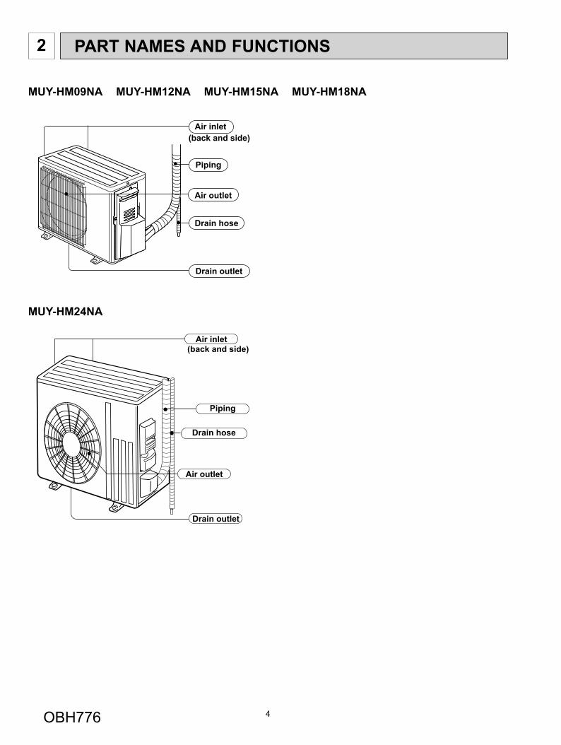
MUY-HM24NA
Piping
Air outlet
Drain outlet
Air inlet(back and side)
Drain hose
PART NAMES AND FUNCTIONS2
MUY-HM09NA MUY-HM12NA MUY-HM15NA MUY-HM18NA
Air outlet
Drain outlet
Piping
Drain hose
Air inlet(back and side)
OBH776
5
3 SPECIFICATION
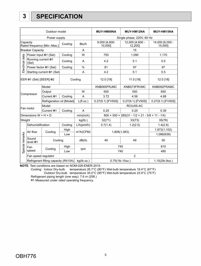
Outdoor model MUY-HM09NA MUY-HM12NA MUY-HM15NA
Power supply Single phase, 220V, 60 HzCapacity Rated frequency [Min.-Max.] Cooling Btu/h 9,000 [4,600-
10,000]12,000 [4,600 -
12,200]14,000 [6,000 -
15,000]Breaker Capacity A 15
Ele
ctric
al d
ata Power input 1 (Set) Cooling W 750 1,090 1,170
Running current 1 (Set) Cooling A 4.2 5.1 5.5
Power factor 1 (Set) Cooling % 81 97 97Starting current 1 (Set) A 4.2 5.1 5.5
EER 1 (Set) [SEER] 2 Cooling 12.0 [18] 11.0 [18] 12.0 [18]
Compressor
Model KNB065FRJMC KNB073FRVMC KNB092FRAMCOutput W 500 550 650Current 1 Cooling A 3.72 4.56 4.68Refrigeration oil [Model] L(fl .oz.) 0.27(9.1) [FV50S] 0.27(9.1) [FV50S] 0.27(9.1) [FV50S]
Fan motorModel RC0J55-ACCurrent 1 Cooling A 0.25 0.25 0.39
Dimensions W × H × D mm(inch) 800 × 550 × 285(31 - 1/2 × 21 - 5/8 × 11 - 1/4)Weight kg(Ib.) 32(71) 33(73) 35(78)
Spe
cial
rem
arks
Dehumidifi cation Cooling L/h(pint/h) 0.7(1.4) 1.2(2.5) 1.4(2.9)
Air fl ow CoolingHigh
m3/h(CFM) 1,806(1,063)1,872(1,102)
Low 1,086(639)Sound level 1 Cooling dB(A) 49 49 50
Fan speed Cooling
High rpm
740 810Low 740 490
Fan speed regulator 2Refrigerant fi lling capacity (R410A) kg(Ib.oz.) 0.75(1Ib.10oz.) 1.15(2Ib.9oz.)
NOTE: Test conditions are based on NOM-026-ENER-2015. Cooling: Indoor Dry-bulb temperature 26.7°C (80°F) Wet-bulb temperature 19.4°C (67°F) Outdoor Dry-bulb temperature 35.0°C (95°F) Wet-bulb temperature 23.9°C (75°F) Refrigerant piping length (one way): 7.6 m (25ft.) 1 Measured under rated operating frequency.
OBH776
6
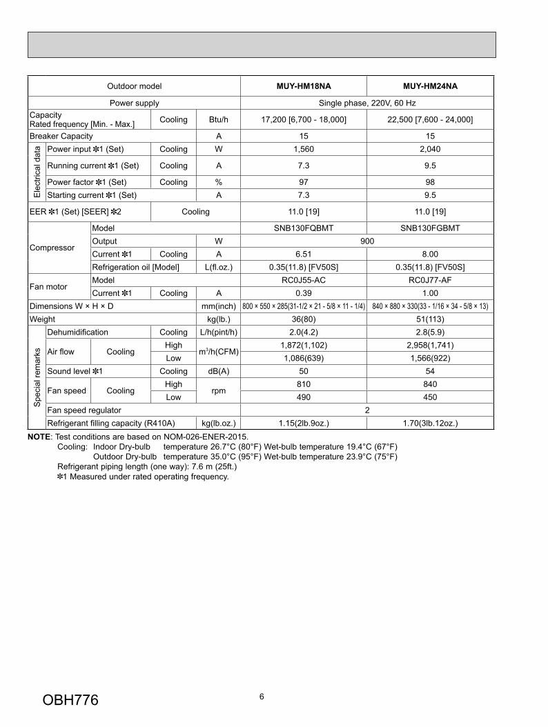
Outdoor model MUY-HM18NA MUY-HM24NA
Power supply Single phase, 220V, 60 HzCapacity Rated frequency [Min. - Max.] Cooling Btu/h 17,200 [6,700 - 18,000] 22,500 [7,600 - 24,000]
Breaker Capacity A 15 15
Ele
ctric
al d
ata Power input 1 (Set) Cooling W 1,560 2,040
Running current 1 (Set) Cooling A 7.3 9.5
Power factor 1 (Set) Cooling % 97 98Starting current 1 (Set) A 7.3 9.5
EER 1 (Set) [SEER] 2 Cooling 11.0 [19] 11.0 [19]
Compressor
Model SNB130FQBMT SNB130FGBMTOutput W 900Current 1 Cooling A 6.51 8.00Refrigeration oil [Model] L(fl .oz.) 0.35(11.8) [FV50S] 0.35(11.8) [FV50S]
Fan motorModel RC0J55-AC RC0J77-AFCurrent 1 Cooling A 0.39 1.00
Dimensions W × H × D mm(inch) 800 × 550 × 285(31-1/2 × 21 - 5/8 × 11 - 1/4) 840 × 880 × 330(33 - 1/16 × 34 - 5/8 × 13)Weight kg(lb.) 36(80) 51(113)
Spe
cial
rem
arks
Dehumidifi cation Cooling L/h(pint/h) 2.0(4.2) 2.8(5.9)
Air fl ow CoolingHigh
m3/h(CFM)1,872(1,102) 2,958(1,741)
Low 1,086(639) 1,566(922)Sound level 1 Cooling dB(A) 50 54
Fan speed CoolingHigh
rpm810 840
Low 490 450Fan speed regulator 2Refrigerant fi lling capacity (R410A) kg(lb.oz.) 1.15(2lb.9oz.) 1.70(3lb.12oz.)
NOTE: Test conditions are based on NOM-026-ENER-2015. Cooling: Indoor Dry-bulb temperature 26.7°C (80°F) Wet-bulb temperature 19.4°C (67°F) Outdoor Dry-bulb temperature 35.0°C (95°F) Wet-bulb temperature 23.9°C (75°F) Refrigerant piping length (one way): 7.6 m (25ft.) 1 Measured under rated operating frequency.
OBH776
7
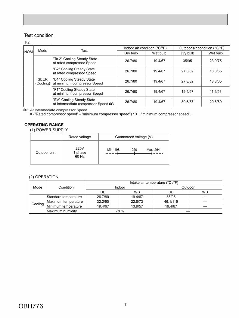
Test condition
NOM Mode Test Indoor air condition (°C/°F) Outdoor air condition (°C/°F)Dry bulb Wet bulb Dry bulb Wet bulb
SEER (Cooling)
"To 2" Cooling Steady State at rated compressor Speed 26.7/80 19.4/67 35/95 23.9/75
"B2" Cooling Steady State at rated compressor Speed 26.7/80 19.4/67 27.8/82 18.3/65
"B1" Cooling Steady State at minimum compressor Speed 26.7/80 19.4/67 27.8/82 18.3/65
"F1" Cooling Steady State at minimum compressor Speed 26.7/80 19.4/67 19.4/67 11.9/53
"EV" Cooling Steady State at Intermediate compressor Speed 3 26.7/80 19.4/67 30.6/87 20.6/69
3: At Intermediate compressor Speed= ("Rated compressor speed" - "minimum compressor speed") / 3 + "minimum compressor speed".
2
(2) OPERATION
Mode ConditionIntake air temperature (°C /°F)
Indoor OutdoorDB WB DB WB
Cooling
Standard temperature 26.7/80 19.4/67 35/95 — Maximum temperature 32.2/90 22.8/73 46.1/115 — Minimum temperature 19.4/67 13.9/57 19.4/67 — Maximum humidity 78 % —
OPERATING RANGE(1) POWER SUPPLY
Rated voltage Guaranteed voltage (V)
Outdoor unit 220V
1 phase 60 Hz
Min. 198 220 Max. 264
OBH776
8
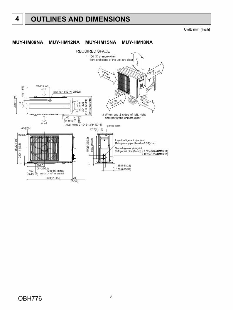
OUTLINES AND DIMENSIONS4Unit: mm (inch)
42
44(1
-3/4
)
285(
11-1
/4)
40
100 (4)or m
ore
350 (14)or more200 (8)
or more *2
100 (4)or more
Liquid refrigerant pipe jointRefrigerant pipe (flared) Ø 6.35(Ø1/4)
Gas refrigerant pipe jointRefrigerant pipe (flared) Ø 9.52(Ø 3/8) (HM09/12) Ø 12.7(Ø 1/2) (HM15/18)
REQUIRED SPACE
clea
r *1
*1 100 (4) or more whenfront and sides of the unit are clear
*2 When any 2 sides of left, right and rear of the unit are clear
oval holes 2-10×21(3/8×13/16)
17.5
344.
5(13
-9/1
6)
304-
325
(12
to 1
2-3/
4)
22.3(7/8)
800(31-1/2)
150
302.5(11-29/32)
500(19-11/16)
70(2-3/4)
550(
21-5
/8)
280(
11-1
/32)
150(
5-29
/32)
98(3
-27/
32)
135(5-11/32)170(6-23/32)
17.7(11/16)
400(15-3/4)
( 1-21/32)
(1-9/16) (11/
16)
(5-15/16)
MUY-HM09NA MUY-HM12NA MUY-HM15NA MUY-HM18NA
OBH776
9
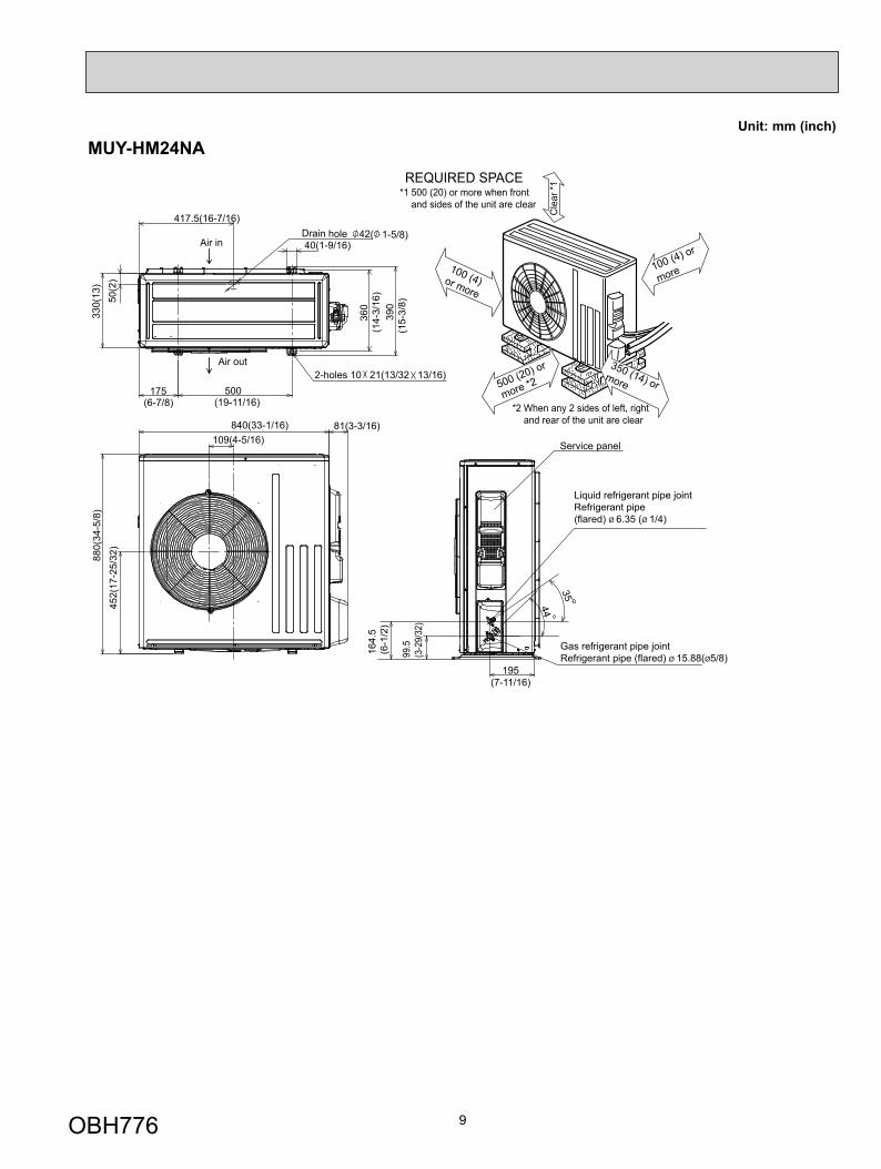
MUY-HM24NA
417.5(16-7/16)
40(1-9/16)42( 1-5/8)Drain hole
175 500
330(
13)
50(2
)
Air in
Air out2-holes 10 21(13/32 13/16)
360
840(33-1/16)109(4-5/16)
81(3-3/16)
880(
34-5
/8)
452(
17-2
5/32
)
Service panel
99.5
(3-2
9/32
)
164.
5(6
-1/2
)
195(7-11/16)
35
44
Liquid refrigerant pipe jointRefrigerant pipe(flared) Ø 6.35 (Ø 1/4)
Gas refrigerant pipe jointRefrigerant pipe (flared) Ø 15.88(Ø5/8)
100 (4)or more
REQUIRED SPACE
100 (4) or
more
350 (14) or more
(14-
3/16
)
(6-7/8) (19-11/16)39
0(1
5-3/
8)
*1 500 (20) or more when front and sides of the unit are clear
*2 When any 2 sides of left, right and rear of the unit are clear
Cle
ar *1
500 (20) or
more *2
Unit: mm (inch)
OBH776
10
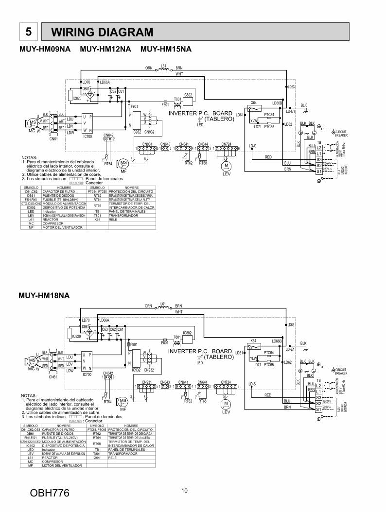
5 WIRING DIAGRAM
MUY-HM18NA
MUY-HM09NA MUY-HM12NA MUY-HM15NA
OBH776
11
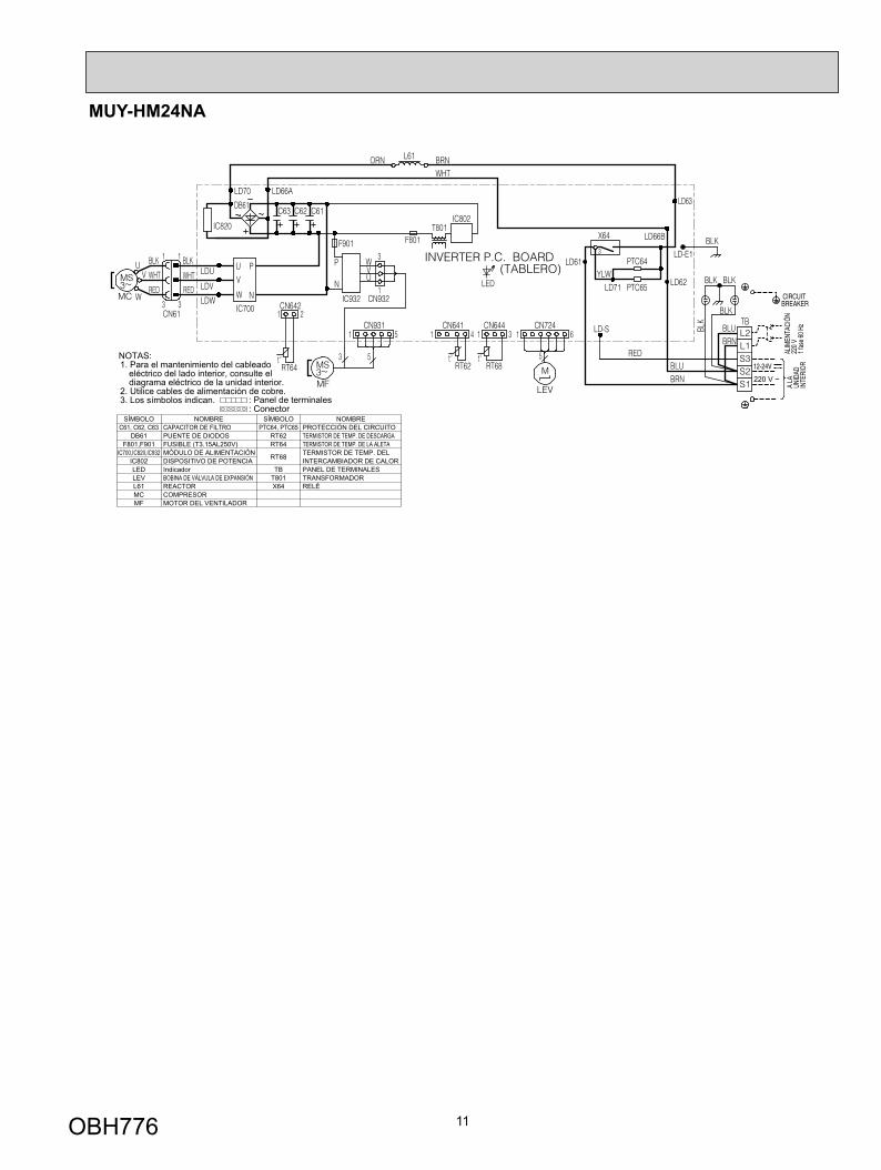
MUY-HM24NA
OBH776
12
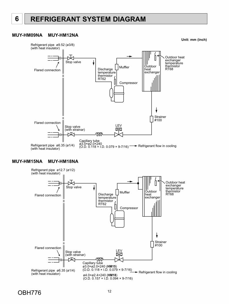
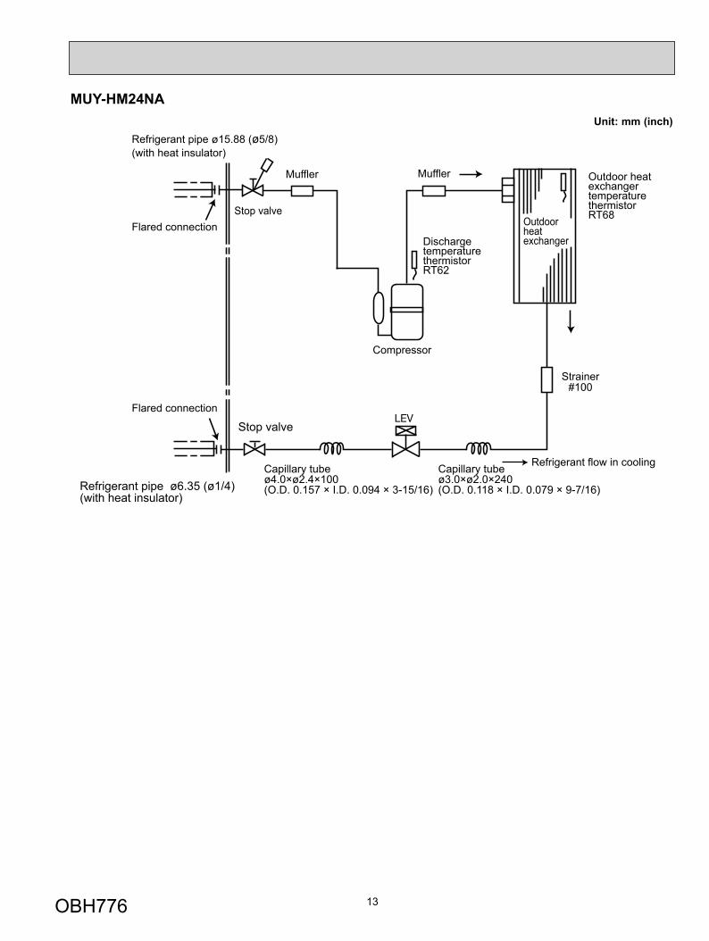
6 REFRIGERANT SYSTEM DIAGRAM
OutdoorheatexchangerFlared connection Discharge
temperaturethermistorRT62
Flared connectionStop valve(with strainar)
Stop valve
Refrigerant flow in cooling
Compressor
Refrigerant pipe ø12.7 (ø1/2)(with heat insulator)
Refrigerant pipe ø6.35 (ø1/4)(with heat insulator)
Strainer#100
LEV
Capillary tubeø3.0×ø2.0×240 (HM15)(O.D. 0.118 × I.D. 0.079 × 9-7/16)
Outdoor heatexchangertemperature thermistorRT68
ø4.0×ø2.4×240 (HM18)(O.D. 0.157 × I.D. 0.094 × 9-7/16)
Muffler
Unit: mm (inch)
OutdoorheatexchangerFlared connection Discharge
temperaturethermistorRT62
Flared connectionStop valve(with strainar)
Stop valve
Refrigerant flow in cooling
Compressor
Refrigerant pipe ø9.52 (ø3/8)(with heat insulator)
Refrigerant pipe ø6.35 (ø1/4)(with heat insulator)
Strainer#100
LEV
Capillary tubeø3.0×ø2.0×240(O.D. 0.118 × I.D. 0.079 × 9-7/16)
Outdoor heatexchangertemperature thermistorRT68Muffler
MUY-HM09NA MUY-HM12NA
MUY-HM15NA MUY-HM18NA
OBH776
13
MUY-HM24NA
Outdoorheatexchanger
Flared connectionDischargetemperaturethermistorRT62
Flared connection
Stop valve
Refrigerant flow in cooling
Compressor
Refrigerant pipe ø15.88 (ø5/8)(with heat insulator)
Muffler Outdoor heat exchanger temperaturethermistorRT68
Strainer#100
Muffler
Stop valve
Refrigerant pipe ø6.35 (ø1/4)(with heat insulator)
Capillary tubeø4.0×ø2.4×100(O.D. 0.157 × I.D. 0.094 × 3-15/16)
Capillary tubeø3.0×ø2.0×240(O.D. 0.118 × I.D. 0.079 × 9-7/16)
Unit: mm (inch)
OBH776
14
Max. Length A
Max. Heightdifference
B
Indoorunit
Outdoor unit
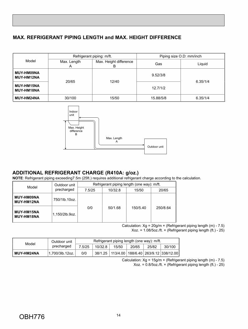
MAX. REFRIGERANT PIPING LENGTH and MAX. HEIGHT DIFFERENCE
Model Refrigerant piping: m/ft. Piping size O.D: mm/inch
Max. Length A
Max. Height difference B Gas Liquid
MUY-HM09NAMUY-HM12NA
20/65 12/40
9.52/3/8
6.35/1/4MUY-HM15NAMUY-HM18NA 12.7/1/2
MUY-HM24NA 30/100 15/50 15.88/5/8 6.35/1/4
ADDITIONAL REFRIGERANT CHARGE (R410A: g/oz.)NOTE: Refrigerant piping exceeding7.5m (25ft.) requires additional refrigerant charge according to the calculation.
Model Outdoor unit precharged
Refrigerant piping length (one way): m/ft.7.5/25 10/32.8 15/50 20/65
MUY-HM09NAMUY-HM12NA 750/1lb.10oz.
0/0 50/1.68 150/5.40 250/8.64MUY-HM15NAMUY-HM18NA 1,150/2lb.9oz.
Calculation: Xg = 20g/m × (Refrigerant piping length (m) - 7.5)Xoz. = 1.08/5oz./ft. × (Refrigerant piping length (ft.) - 25)
Model Outdoor unit precharged
Refrigerant piping length (one way): m/ft.7.5/25 10/32.8 15/50 20/65 25/82 30/100
MUY-HM24NA 1,700/3lb.12oz. 0/0 38/1.25 113/4.00 188/6.40 263/9.12 338/12.00
Calculation: Xg = 15g/m × (Refrigerant piping length (m) - 7.5)Xoz. = 0.8/5oz./ft. × (Refrigerant piping length (ft.) - 25)
OBH776
15
DATA7
MUY-HM09NA MUY-HM12NA MUY-HM15NA MUY-HM18NA MUY-HM24NA
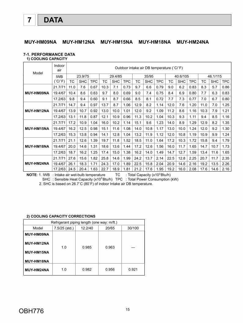
7-1. PERFORMANCE DATA 1) COOLING CAPACITY
Model
Indoor air Outdoor intake air DB temperature (˚C/˚F)
IWB (˚C/˚F)
23.9/75 29.4/85 35/95 40.6/105 46.1/115TC SHC TPC TC SHC TPC TC SHC TPC TC SHC TPC TC SHC TPC
MUY-HM09NA21.7/71 11.0 7.6 0.67 10.3 7.1 0.73 9.7 6.6 0.79 9.0 6.2 0.83 8.3 5.7 0.8619.4/67 10.4 8.6 0.63 9.7 8.0 0.69 9.0 7.4 0.75 8.4 6.9 0.80 7.7 6.3 0.8317.2/63 9.8 9.4 0.60 9.1 8.7 0.66 8.5 8.1 0.72 7.7 7.3 0.77 7.0 6.7 0.80
MUY-HM12NA21.7/71 14.7 9.4 0.97 13.7 8.7 1.06 12.9 8.2 1.14 12.0 7.6 1.20 11.0 7.0 1.2519.4/67 13.9 10.7 0.92 13.0 10.0 1.01 12.0 9.2 1.09 11.2 8.6 1.16 10.3 7.9 1.2117.2/63 13.1 11.8 0.87 12.1 10.9 0.96 11.3 10.2 1.04 10.3 9.3 1.11 9.4 8.5 1.16
MUY-HM15NA21.7/71 17.2 10.9 1.04 16.0 10.2 1.14 15.1 9.6 1.23 14.0 8.9 1.29 12.9 8.2 1.3519.4/67 16.2 12.5 0.98 15.1 11.6 1.08 14.0 10.8 1.17 13.0 10.0 1.24 12.0 9.2 1.3017.2/63 15.3 13.8 0.94 14.1 12.8 1.04 13.2 11.9 1.12 12.0 10.8 1.19 10.9 9.9 1.24
MUY-HM18NA21.7/71 21.1 12.6 1.39 19.7 11.8 1.52 18.5 11.0 1.64 17.2 10.3 1.72 15.8 9.4 1.7919.4/67 20.0 14.6 1.31 18.6 13.6 1.44 17.2 12.6 1.56 16.0 11.7 1.65 14.7 10.7 1.7317.2/63 18.7 16.2 1.25 17.4 15.0 1.38 16.2 14.0 1.49 14.7 12.7 1.59 13.4 11.6 1.65
MUY-HM24NA21.7/71 27.6 15.6 1.82 25.8 14.6 1.99 24.2 13.7 2.14 22.5 12.8 2.25 20.7 11.7 2.3519.4/67 26.1 18.3 1.71 24.3 17.0 1.89 22.5 15.8 2.04 20.9 14.6 2.16 19.2 13.5 2.2617.2/63 24.5 20.4 1.63 22.7 18.9 1.81 21.2 17.6 1.95 19.2 16.0 2.08 17.6 14.6 2.16
NOTE: 1. IWB : Intake air wet-bulb temperature TC : Total Capacity (x103 Btu/h)SHC : Sensible Heat Capacity (x103 Btu/h) TPC : Total Power Consumption (kW)
2. SHC is based on 26.7˚C (80˚F) of indoor Intake air DB temperature.
2) COOLING CAPACITY CORRECTIONSRefrigerant piping length (one way: m/ft.)
Model 7.5/25 (std.) 12.2/40 20/65 30/100
MUY-HM09NA
MUY-HM12NA
MUY-HM15NA
MUY-HM18NA
1.0 0.985 0.963 —
MUY-HM24NA 1.0 0.982 0.956 0.921
OBH776
16
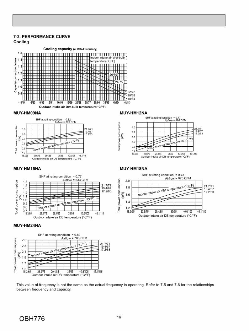
7-2. PERFORMANCE CURVECooling
Cooling capacity (at Rated frequency)
0.9
1.0
1.1
1.2
1.3
1.4
1.5
-10/14 -5/23 0/32 5/41 10/50 15/59 20/68 25/77 30/86 35/95 40/104 45/113Outdoor intake air Dry-bulb temperature(°C/°F)
Cap
acity
cor
rect
ion
fact
ors
26/79
24/75
20/6818/64
22/72
Indoor intake air Wet-bulbtemperature( C/ F)
21.7/7119.4/6717.2/63
18.3/65 23.9/75 29.4/85 35/95 40.6/105 46.1/1150.4
0.5
0.6
0.7
0.8
0.9
Indoor intake air WB temperature (°C/°F)
SHF at rating condition = 0.82= 399 CFMAirflow
Outdoor intake air DB temperature (°C/°F)
Tota
l pow
er c
onsu
mpt
ion
(kW
)
21.7/7119.4/6717.2/63
18.3/65 23.9/75 29.4/85 35/95 40.6/105 46.1/1150.8
0.9
1.0
1.1
1.2
1.3
Indoor intake air WB temperature (°C/°F)
SHF at rating condition = 0.77= 498 CFMAirflow
Outdoor intake air DB temperature (°C/°F)
Tota
l pow
er c
onsu
mpt
ion
(kW
)
MUY-HM09NA MUY-HM12NA
MUY-HM24NA
MUY-HM18NA
21.7/7119.4/6717.2/63
18.3/65 23.9/75 29.4/85 35/95 40.6/105 46.1/1151.5
1.7
1.9
2.1
2.3
2.5
Indoor intake air WB temperature (°C/°F)
SHF at rating condition = 0.89= 703 CFMAirflow
Outdoor intake air DB temperature (°C/°F)
Tota
l pow
er c
onsu
mpt
ion
(kW
)
21.7/7119.4/6717.2/63
18.3/65 23.9/75 29.4/85 35/95 40.6/105 46.1/1150.70.80.91.01.11.21.31.41.5
Indoor intake air WB temperature (°C/°F)
SHF at rating condition = 0.77= 533 CFMAirflow
Outdoor intake air DB temperature (°C/°F)
Tota
l pow
er c
onsu
mpt
ion
(kW
)
21.7/7119.4/6717.2/63
18.3/65 23.9/75 29.4/85 35/95 40.6/105 46.1/1151.2
1.4
1.6
1.8
Indoor intake air WB temperature (°C/°F)2.0
SHF at rating condition = 0.73= 625 CFMAirflow
Outdoor intake air DB temperature (°C/°F)
Tota
l pow
er c
onsu
mpt
ion
(kW
)
MUY-HM15NA
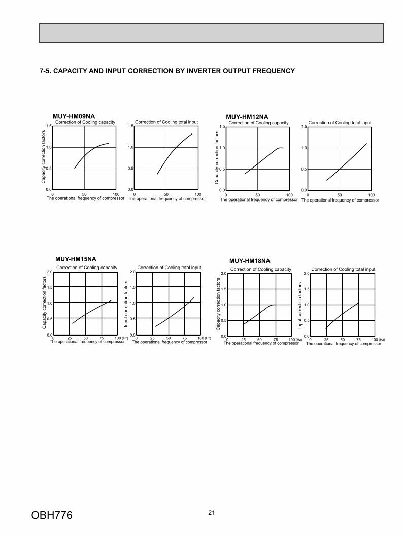
This value of frequency is not the same as the actual frequency in operating. Refer to 7-5 and 7-6 for the relationships between frequency and capacity.
OBH776
17
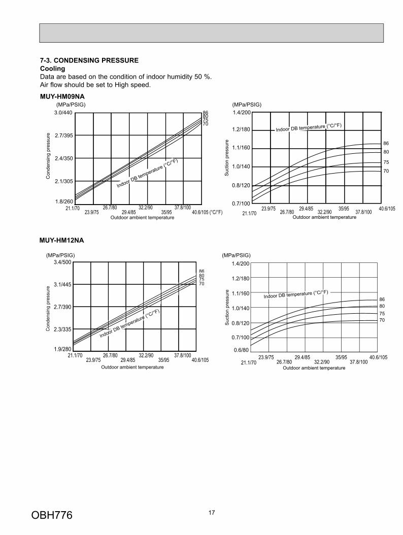
7-3. CONDENSING PRESSURECoolingData are based on the condition of indoor humidity 50 %.Air flow should be set to High speed.
MUY-HM09NA
21.1/7023.9/75 26.7/80 29.4/85 32.2/90 35/95 37.8/100 40.6/105
0.7/100
0.8/120
1.0/140
1.1/160
1.2/180
1.4/200(MPa/PSIG)(MPa/PSIG)
1.8/260
2.1/305
2.4/350
2.7/395
3.0/440
21.1/7023.9/75
26.7/8029.4/85
32.2/9035/95
37.8/10040.6/105 (°C/°F)
Con
dens
ing
pres
sure
86807570
Suc
tion
pres
sure
Outdoor ambient temperature
Indoor DB temperature (°C/°F)
Indoor DB temperature (°C/°F)
86
80
75
70
Outdoor ambient temperature
MUY-HM12NA
21.1/7023.9/75
26.7/8029.4/85
32.2/9035/95
37.8/10040.6/105
0.6/80
0.7/100
0.8/120
1.0/140
1.1/160
1.2/180
1.4/200(MPa/PSIG)(MPa/PSIG)
21.1/7023.9/75
26.7/8029.4/85
32.2/9035/95
37.8/10040.6/105
1.9/280
2.3/335
2.7/390
3.1/445
3.4/500
Con
dens
ing
pres
sure
86807570
Suc
tion
pres
sure
F)
Indoor DB temperature (°C/°F)
oom
e
DB
Outdoor ambient temperature
Indoor DB temperature (°C/°F)86807570
Outdoor ambient temperature
OBH776
18
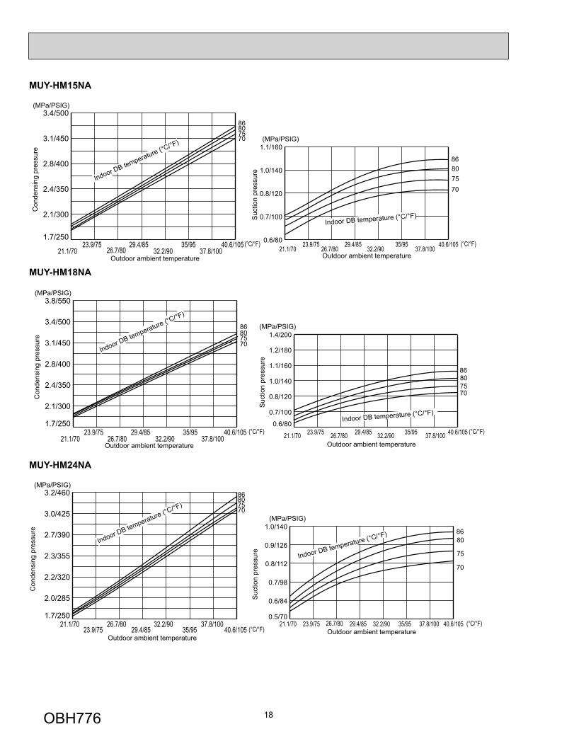
MUY-HM24NA
MUY-HM18NA
21.1/7023.9/75
26.7/8029.4/85
32.2/9035/95
37.8/10040.6/105
1.7/250
2.0/285
2.2/320
2.3/355
2.7/390
3.0/425
3.2/460
(°C/°F)21.1/70 23.9/75 26.7/80 29.4/85 32.2/90 35/95 37.8/100 40.6/1050.5/70
0.6/84
0.7/98
0.8/112
0.9/126
1.0/140
(°C/°F)
(MPa/PSIG)
Con
dens
ing
pres
sure
Suc
tion
pres
sure
Outdoor ambient temperature
Indoor DB temperature (°C/°F)
(MPa/PSIG)
Indoor DB temperature (°C/°F)
Outdoor ambient temperature
86807570
8680
75
70
21.1/7023.9/75
26.7/8029.4/85
32.2/9035/95
37.8/10040.6/105
1.7/250
2.1/300
2.4/350
2.8/400
3.1/450
3.4/500
3.8/550
(°C/°F) (°C/°F)21.1/70 23.9/75 26.7/80 29.4/85 32.2/90 35/95 37.8/100 40.6/1050.6/80
0.7/100
0.8/120
1.0/140
1.1/160
1.2/180
1.4/200
(MPa/PSIG)
Con
dens
ing
pres
sure
Suc
tion
pres
sure
Outdoor ambient temperature
Indoor DB temperature (°C/°F)
(MPa/PSIG)
Indoor DB temperature (°C/°F)
Outdoor ambient temperature
86807570
86807570
(°C/°F)21.1/70
23.9/7526.7/80
29.4/8532.2/90
35/9537.8/100
40.6/1050.6/80
0.7/100
0.8/120
1.0/140
1.1/160
(MPa/PSIG)
Con
dens
ing
pres
sure
Suc
tion
pres
sure
Outdoor ambient temperature
Indoor DB temperature (°C/°F)
(MPa/PSIG)
21.1/7023.9/75
26.7/8029.4/85
32.2/9035/95
37.8/10040.6/105
1.7/250
2.1/300
2.4/350
2.8/400
3.1/450
3.4/500
(°C/°F)
Indoor DB temperature (°C/°F)
Outdoor ambient temperature
86807570
86807570
MUY-HM15NA
OBH776
19
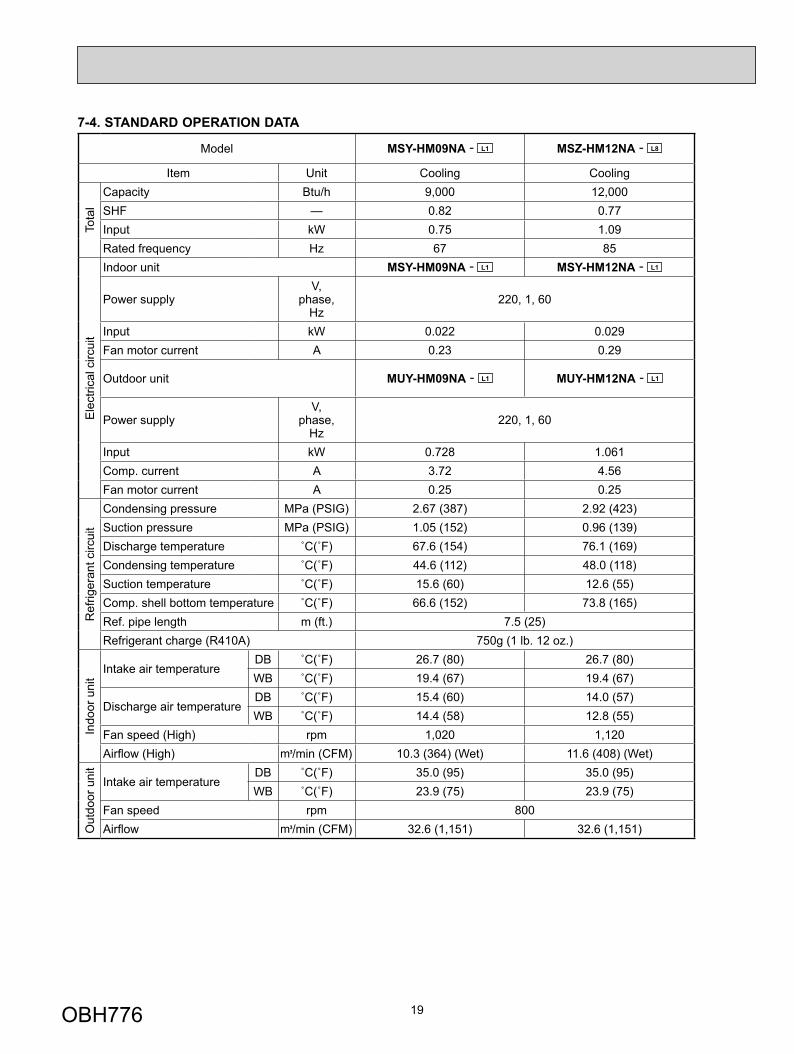
7-4. STANDARD OPERATION DATA
Model MSY-HM09NA - L1 MSZ-HM12NA - L8
Item Unit Cooling Cooling
Tota
l
Capacity Btu/h 9,000 12,000SHF — 0.82 0.77Input kW 0.75 1.09Rated frequency Hz 67 85
Ele
ctric
al c
ircui
t
Indoor unit MSY-HM09NA - L1 MSY-HM12NA - L1
Power supplyV,
phase, Hz
220, 1, 60
Input kW 0.022 0.029Fan motor current A 0.23 0.29
Outdoor unit MUY-HM09NA - L1 MUY-HM12NA - L1
Power supplyV,
phase, Hz
220, 1, 60
Input kW 0.728 1.061Comp. current A 3.72 4.56Fan motor current A 0.25 0.25
Ref
riger
ant c
ircui
t
Condensing pressure MPa (PSIG) 2.67 (387) 2.92 (423)Suction pressure MPa (PSIG) 1.05 (152) 0.96 (139)Discharge temperature ˚C(˚F) 67.6 (154) 76.1 (169)Condensing temperature ˚C(˚F) 44.6 (112) 48.0 (118)Suction temperature ˚C(˚F) 15.6 (60) 12.6 (55)Comp. shell bottom temperature ˚C(˚F) 66.6 (152) 73.8 (165)Ref. pipe length m (ft.) 7.5 (25)Refrigerant charge (R410A) 750g (1 lb. 12 oz.)
Indo
or u
nit
Intake air temperatureDB ˚C(˚F) 26.7 (80) 26.7 (80)WB ˚C(˚F) 19.4 (67) 19.4 (67)
Discharge air temperatureDB ˚C(˚F) 15.4 (60) 14.0 (57)WB ˚C(˚F) 14.4 (58) 12.8 (55)
Fan speed (High) rpm 1,020 1,120Airfl ow (High) /min (CFM) 10.3 (364) (Wet) 11.6 (408) (Wet)
Out
door
uni
t
Intake air temperatureDB ˚C(˚F) 35.0 (95) 35.0 (95)WB ˚C(˚F) 23.9 (75) 23.9 (75)
Fan speed rpm 800Airfl ow /min (CFM) 32.6 (1,151) 32.6 (1,151)
OBH776
20
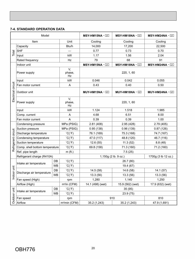
7-4. STANDARD OPERATION DATA
Model MSY-HM15NA - L1 MSY-HM18NA - L1 MSY-HM24NA - L1
Item Unit Cooling Cooling Cooling
Tota
l
Capacity Btu/h 14,000 17,200 22,500SHF — 0.77 0.73 0.70Input kW 1.17 1.56 2.04Rated frequency Hz 79 68 91
Ele
ctric
al c
ircui
t
Indoor unit MSY-HM15NA - L1 MSY-HM18NA - L1 MSY-HM24NA - L1
Power supplyV,
phase, Hz
220, 1, 60
Input kW 0.046 0.042 0.055Fan motor current A 0.43 0.40 0.50
Outdoor unit MUY-HM15NA - L1 MUY-HM18NA - L1 MUY-HM24NA - L1
Power supplyV,
phase, Hz
220, 1, 60
Input kW 1.124 1.518 1.985Comp. current A 4.68 6.51 8.00Fan motor current A 0.39 0.39 1.00
Ref
riger
ant c
ircui
t
Condensing pressure MPa (PSIG) 2.81 (408) 2.95 (428) 2.79 (405)Suction pressure MPa (PSIG) 0.95 (138) 0.96 (139) 0.87 (126)Discharge temperature ˚C(˚F) 76.1 (169) 75.3 (168) 74.7 (167)Condensing temperature ˚C(˚F) 47.0 (117) 48.8 (120) 46.7 (116)Suction temperature ˚C(˚F) 12.6 (55) 11.3 (52) 8.8 (48)Comp. shell bottom temperature ˚C(˚F) 69.8 (158) 71.3 (160) 71.2 (160)Ref. pipe length m (ft.) 7.5 (25)Refrigerant charge (R410A) 1,150g (2 lb. 9 oz.) 1700g (3 lb 12 oz.)
Indo
or u
nit
Intake air temperatureDB ˚C(˚F) 26.7 (80)WB ˚C(˚F) 19.4 (67)
Discharge air temperatureDB ˚C(˚F) 14.5 (58) 14.6 (58) 14.1 (57)WB ˚C(˚F) 13.3 (56) 13.3 (56) 13.3 (56)
Fan speed (High) rpm 1,280 1,140 1,250Airfl ow (High) /in (CFM) 14.1 (498) (wet) 15.9 (562) (wet) 17.9 (632) (wet)
Out
door
uni
t
Intake air temperatureDB ˚C(˚F) 35 (95)WB ˚C(˚F) 23.9 (75)
Fan speed rpm 910 810Airfl ow /min (CFM) 35.2 (1,243) 35.2 (1,243) 47.9 (1,691)
OBH776
21
7-5. CAPACITY AND INPUT CORRECTION BY INVERTER OUTPUT FREQUENCY
Cap
acity
cor
rect
ion
fact
ors
Correction of Cooling capacity
The operational frequency of compressor
Correction of Cooling total input
The operational frequency of compressor
MUY-HM09NA
0 50 1000.0
0.5
1.0
1.5
0 50 1000.0
0.5
1.0
1.5
Cap
acity
cor
rect
ion
fact
ors
Correction of Cooling capacity
The operational frequency of compressor
Correction of Cooling total input
The operational frequency of compressor
MUY-HM12NA
0 50 1000.0
0.5
1.0
1.5
0 50 1000.0
0.5
1.0
1.5
0 25 50 75 1000.0
0.5
1.0
1.5
2.0
0 25 50 75 1000.0
0.5
1.0
1.5
2.0
0 25 50 75 1000.0
0.5
1.0
1.5
2.0
0 25 50 75 1000.0
0.5
1.0
1.5
2.0
MUY-HM15NA MUY-HM18NA
Cap
acity
cor
rect
ion
fact
ors
Inpu
t cor
rect
ion
fact
ors
Correction of Cooling capacity
The operational frequency of compressor
Correction of Cooling total input
The operational frequency of compressor(Hz) (Hz)
Cap
acity
cor
rect
ion
fact
ors
Inpu
t cor
rect
ion
fact
ors
Correction of Cooling capacity
The operational frequency of compressor
Correction of Cooling total input
The operational frequency of compressor(Hz) (Hz)
OBH776
22
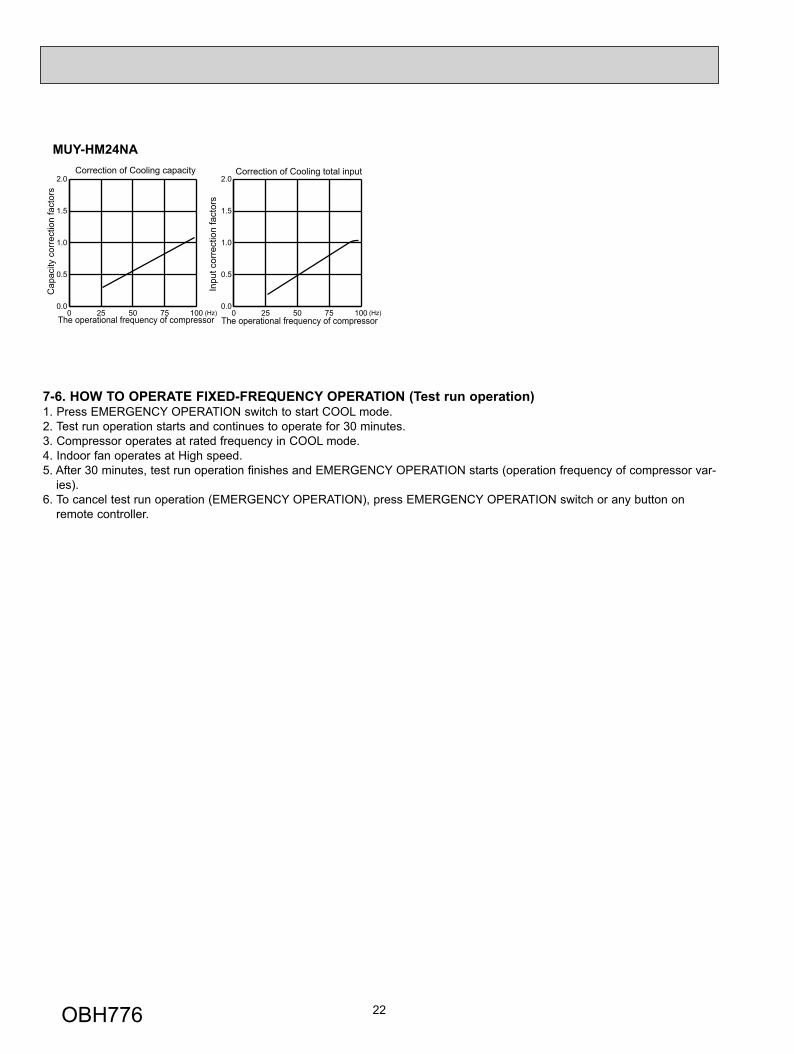
7-6. HOW TO OPERATE FIXED-FREQUENCY OPERATION (Test run operation)1. Press EMERGENCY OPERATION switch to start COOL mode.2. Test run operation starts and continues to operate for 30 minutes.3. Compressor operates at rated frequency in COOL mode.4. Indoor fan operates at High speed.5. After 30 minutes, test run operation finishes and EMERGENCY OPERATION starts (operation frequency of compressor var-
ies).6. To cancel test run operation (EMERGENCY OPERATION), press EMERGENCY OPERATION switch or any button on
remote controller.
0 25 50 75 1000.0
0.5
1.0
1.5
2.0
0 25 50 75 1000.0
0.5
1.0
1.5
2.0
MUY-HM24NA
Cap
acity
cor
rect
ion
fact
ors
Inpu
t cor
rect
ion
fact
ors
Correction of Cooling capacity
The operational frequency of compressor
Correction of Cooling total input
The operational frequency of compressor(Hz) (Hz)
OBH776
23
8 ACTUATOR CONTROL
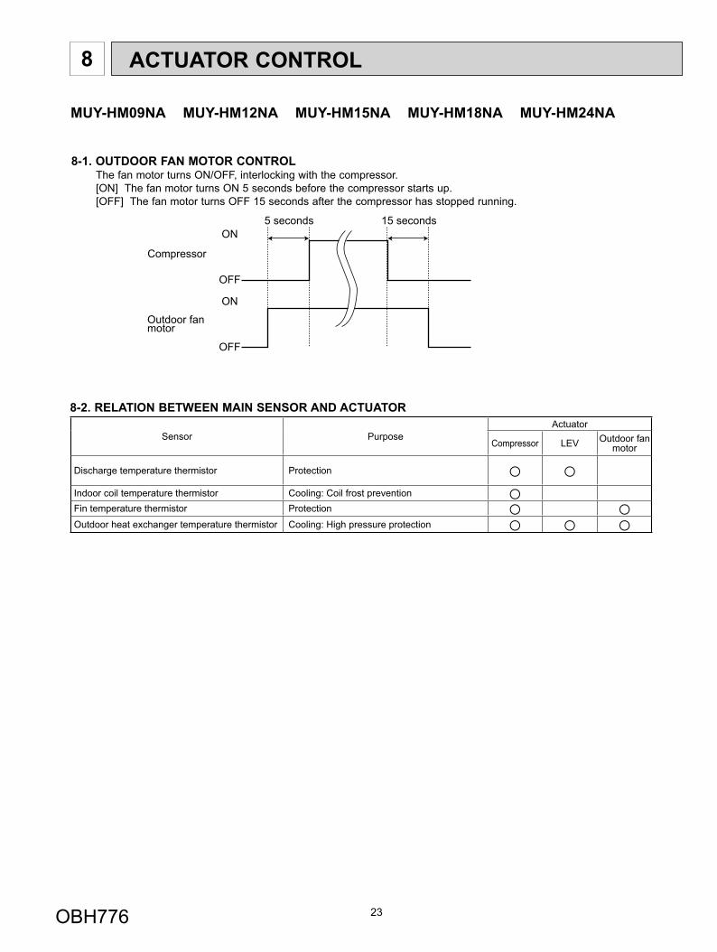
ON
OFF
ON
OFF
Outdoor fanmotor
Compressor
5 seconds 15 seconds
8-1. OUTDOOR FAN MOTOR CONTROLThe fan motor turns ON/OFF, interlocking with the compressor.[ON] The fan motor turns ON 5 seconds before the compressor starts up.[OFF] The fan motor turns OFF 15 seconds after the compressor has stopped running.
8-2. RELATION BETWEEN MAIN SENSOR AND ACTUATOR
Sensor PurposeActuator
Compressor LEV Outdoor fan motor
Discharge temperature thermistor Protection ○ ○Indoor coil temperature thermistor Cooling: Coil frost prevention ○Fin temperature thermistor Protection ○ ○Outdoor heat exchanger temperature thermistor Cooling: High pressure protection ○ ○ ○
MUY-HM09NA MUY-HM12NA MUY-HM15NA MUY-HM18NA MUY-HM24NA
OBH776
24
9 SERVICE FUNCTIONS
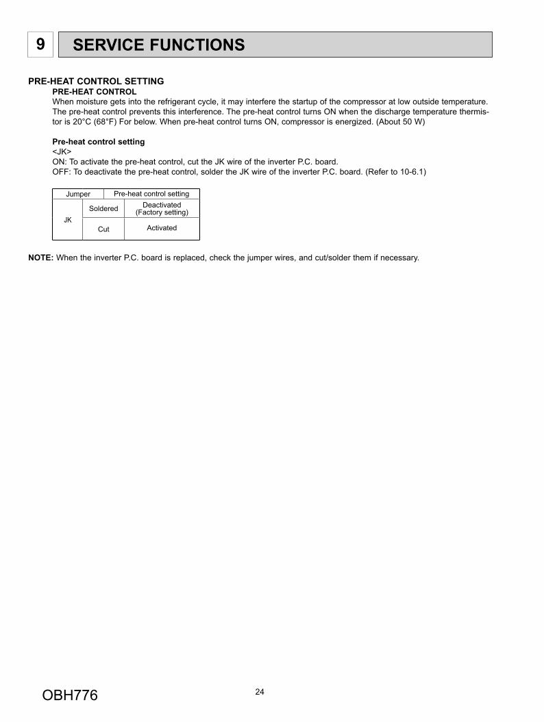
PRE-HEAT CONTROL SETTINGPRE-HEAT CONTROLWhen moisture gets into the refrigerant cycle, it may interfere the startup of the compressor at low outside temperature. The pre-heat control prevents this interference. The pre-heat control turns ON when the discharge temperature thermis-tor is 20°C (68°F) For below. When pre-heat control turns ON, compressor is energized. (About 50 W)
Pre-heat control setting<JK> ON: To activate the pre-heat control, cut the JK wire of the inverter P.C. board.OFF: To deactivate the pre-heat control, solder the JK wire of the inverter P.C. board. (Refer to 10-6.1)
Jumper Pre-heat control setting
JKSoldered Deactivated
(Factory setting)
Cut Activated
NOTE: When the inverter P.C. board is replaced, check the jumper wires, and cut/solder them if necessary.
OBH776
25
10 TROUBLESHOOTING
10-1. CAUTIONS ON TROUBLESHOOTING1. Before troubleshooting, check the following
1) Check the power supply voltage.2) Check the indoor/outdoor connecting wire for miswiring.
2. Take care of the following during servicing1) Before servicing the air conditioner, be sure to turn OFF the main unit first with the remote controller, then after con-
firming the horizontal vane is closed, turn off the breaker and/or disconnect the power plug.2) Be sure to turn OFF the power supply before removing the front panel, the cabinet, the top panel, and the electronic
control P.C. board.3) When removing the electrical parts, be careful of the residual voltage of smoothing capacitor. 4) When removing the electronic control P.C. board, hold the edge of the board with care NOT to apply stress on the
components.
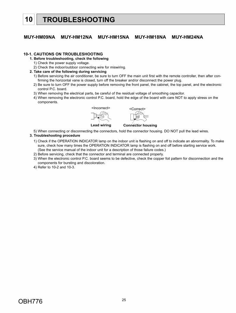
5) When connecting or disconnecting the connectors, hold the connector housing. DO NOT pull the lead wires.3. Troubleshooting procedure
1) Check if the OPERATION INDICATOR lamp on the indoor unit is flashing on and off to indicate an abnormality. To make sure, check how many times the OPERATION INDICATOR lamp is flashing on and off before starting service work. (See the service manual of the indoor unit for a description of those failure codes.)
2) Before servicing, check that the connector and terminal are connected properly.3) When the electronic control P.C. board seems to be defective, check the copper foil pattern for disconnection and the
components for bursting and discoloration.4) Refer to 10-2 and 10-3.
Lead wiring
<Incorrect>
Connector housing
<Correct>
MUY-HM09NA MUY-HM12NA MUY-HM15NA MUY-HM18NA MUY-HM24NA
OBH776
26
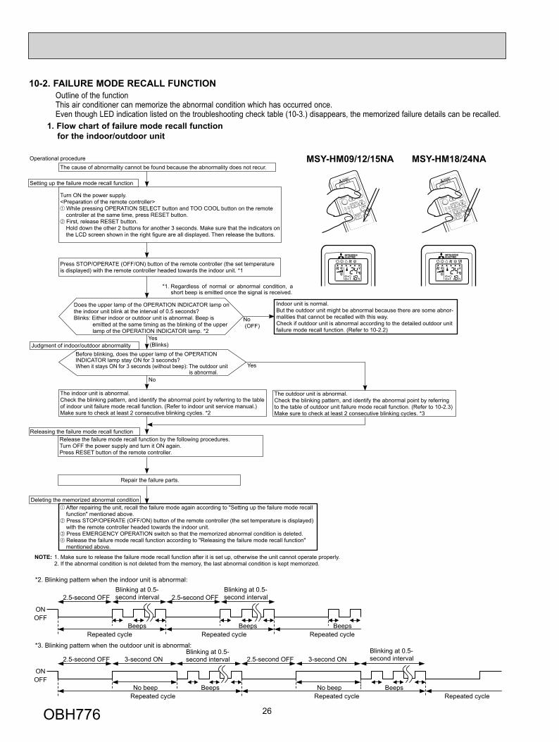
Outline of the functionThis air conditioner can memorize the abnormal condition which has occurred once.Even though LED indication listed on the troubleshooting check table (10-3.) disappears, the memorized failure details can be recalled.
10-2. FAILURE MODE RECALL FUNCTION
1. Flow chart of failure mode recall function for the indoor/outdoor unit
NOTE: 1. Make sure to release the failure mode recall function after it is set up, otherwise the unit cannot operate properly. 2. If the abnormal condition is not deleted from the memory, the last abnormal condition is kept memorized.
Does the upper lamp of the OPERATION INDICATOR lamp on the indoor unit blink at the interval of 0.5 seconds?Blinks: Either indoor or outdoor unit is abnormal. Beep is
emitted at the same timing as the blinking of the upper lamp of the OPERATION INDICATOR lamp. *2
Indoor unit is normal.But the outdoor unit might be abnormal because there are some abnor-malities that cannot be recalled with this way.Check if outdoor unit is abnormal according to the detailed outdoor unit failure mode recall function. (Refer to 10-2.2)
No
Yes
The cause of abnormality cannot be found because the abnormality does not recur.
Setting up the failure mode recall function
Turn ON the power supply.<Preparation of the remote controller>
While pressing OPERATION SELECT button and TOO COOL button on the remote controller at the same time, press RESET button. First, release RESET button.
Hold down the other 2 buttons for another 3 seconds. Make sure that the indicators on the LCD screen shown in the right fi gure are all displayed. Then release the buttons.
Press STOP/OPERATE (OFF/ON) button of the remote controller (the set temperature is displayed) with the remote controller headed towards the indoor unit. *1
Judgment of indoor/outdoor abnormalityBefore blinking, does the upper lamp of the OPERATION INDICATOR lamp stay ON for 3 seconds?When it stays ON for 3 seconds (without beep): The outdoor unit
is abnormal.
The indoor unit is abnormal.Check the blinking pattern, and identify the abnormal point by referring to the table of indoor unit failure mode recall function. (Refer to indoor unit service manual.)Make sure to check at least 2 consecutive blinking cycles. *2
Releasing the failure mode recall functionRelease the failure mode recall function by the following procedures.Turn OFF the power supply and turn it ON again.Press RESET button of the remote controller.
The outdoor unit is abnormal.Check the blinking pattern, and identify the abnormal point by referring to the table of outdoor unit failure mode recall function. (Refer to 10-2.3)Make sure to check at least 2 consecutive blinking cycles. *3
Repair the failure parts.
Deleting the memorized abnormal condition After repairing the unit, recall the failure mode again according to "Setting up the failure mode recall function" mentioned above. Press STOP/OPERATE (OFF/ON) button of the remote controller (the set temperature is displayed) with the remote controller headed towards the indoor unit. Press EMERGENCY OPERATION switch so that the memorized abnormal condition is deleted. Release the failure mode recall function according to "Releasing the failure mode recall function" mentioned above.
Operational procedure
Yes (Blinks)
No (OFF)
*1. Regardless of normal or abnormal condition, a short beep is emitted once the signal is received.
*2. Blinking pattern when the indoor unit is abnormal:
*3. Blinking pattern when the outdoor unit is abnormal:
ONOFF
BeepsRepeated cycle Repeated cycle
ONOFF
No beep BeepsRepeated cycle
2.5-second OFFBlinking at 0.5-second interval
2.5-second OFF 3-second ONBlinking at 0.5-second interval
BeepsRepeated cycle
2.5-second OFFBlinking at 0.5-second interval
No beep BeepsRepeated cycle
2.5-second OFF 3-second ONBlinking at 0.5-second interval
Repeated cycle
Beeps
MSY-HM09/12/15NA MSY-HM18/24NA
OBH776
27
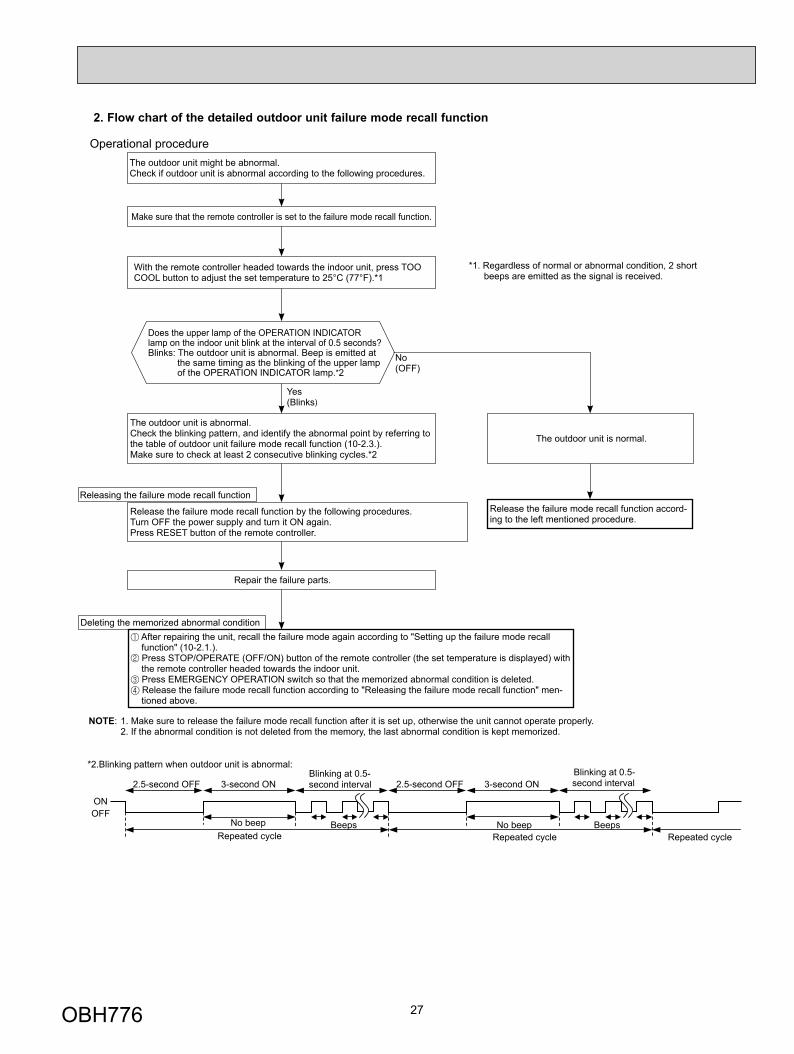
2. Flow chart of the detailed outdoor unit failure mode recall function
*2.Blinking pattern when outdoor unit is abnormal:
ONOFF
No beep BeepsRepeated cycle
2.5-second OFF 3-second ONBlinking at 0.5-second interval
No beep BeepsRepeated cycle
2.5-second OFF 3-second ONBlinking at 0.5-second interval
Repeated cycle
Does the upper lamp of the OPERATION INDICATOR lamp on the indoor unit blink at the interval of 0.5 seconds?Blinks: The outdoor unit is abnormal. Beep is emitted at
the same timing as the blinking of the upper lamp of the OPERATION INDICATOR lamp.*2
Yes(Blinks)
No(OFF)
The outdoor unit might be abnormal.Check if outdoor unit is abnormal according to the following procedures.
Operational procedure
Make sure that the remote controller is set to the failure mode recall function.
With the remote controller headed towards the indoor unit, press TOO COOL button to adjust the set temperature to 25°C (77°F).*1
*1. Regardless of normal or abnormal condition, 2 short beeps are emitted as the signal is received.
The outdoor unit is abnormal.Check the blinking pattern, and identify the abnormal point by referring to the table of outdoor unit failure mode recall function (10-2.3.).Make sure to check at least 2 consecutive blinking cycles.*2
Releasing the failure mode recall function
Release the failure mode recall function by the following procedures.Turn OFF the power supply and turn it ON again.Press RESET button of the remote controller.
Repair the failure parts.
The outdoor unit is normal.
Release the failure mode recall function accord-ing to the left mentioned procedure.
Deleting the memorized abnormal condition After repairing the unit, recall the failure mode again according to "Setting up the failure mode recall function" (10-2.1.). Press STOP/OPERATE (OFF/ON) button of the remote controller (the set temperature is displayed) with the remote controller headed towards the indoor unit. Press EMERGENCY OPERATION switch so that the memorized abnormal condition is deleted. Release the failure mode recall function according to "Releasing the failure mode recall function" men-tioned above.
NOTE: 1. Make sure to release the failure mode recall function after it is set up, otherwise the unit cannot operate properly. 2. If the abnormal condition is not deleted from the memory, the last abnormal condition is kept memorized.
OBH776
28
The upper lamp of the
OPERATION INDICATOR
lamp(Indoor unit)
Abnormal point (Failure mode/protection)
LED indication(Outdoor P.C. board) Condition Remedy
Indoor/outdoor unit failure mode recall
function
Outdoor unit failure mode
recall function
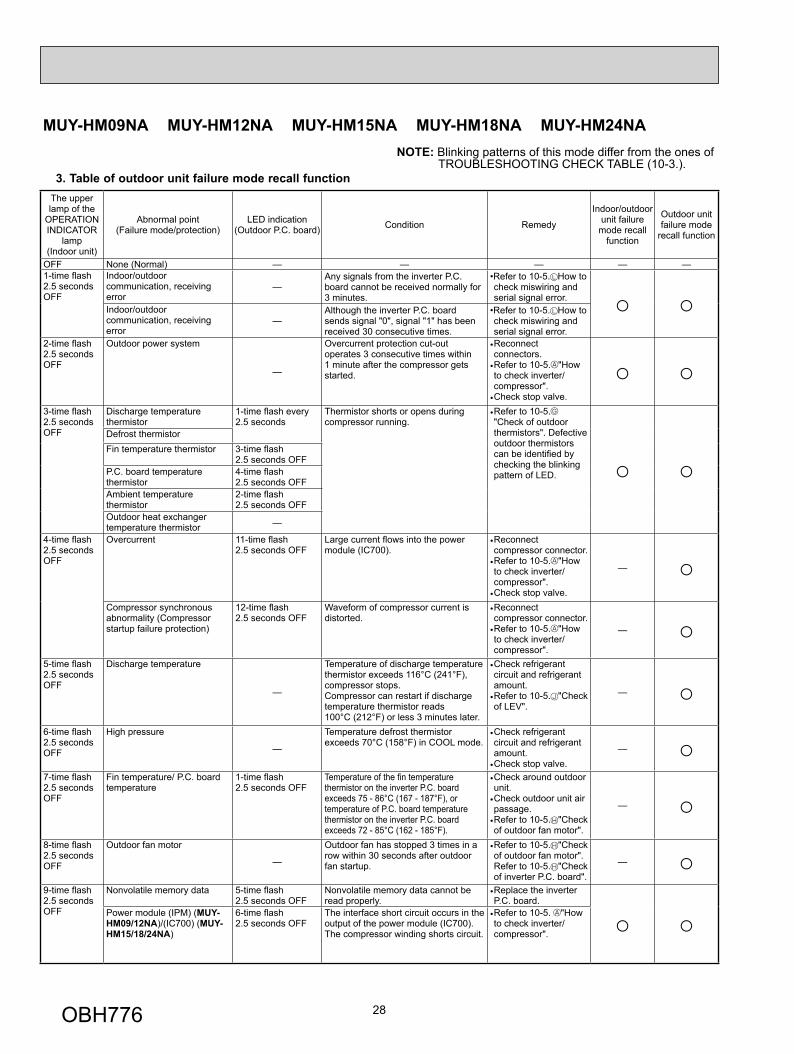
OFF None (Normal) — — — — —1-time fl ash 2.5 seconds OFF
Indoor/outdoor communication, receiving error
—Any signals from the inverter P.C. board cannot be received normally for 3 minutes.
•Refer to 10-5. How to check miswiring and serial signal error. ○ ○Indoor/outdoor
communication, receiving error
—Although the inverter P.C. board sends signal "0", signal "1" has been received 30 consecutive times.
•Refer to 10-5. How to check miswiring and serial signal error.
2-time fl ash 2.5 seconds OFF
Outdoor power system
—
Overcurrent protection cut-out operates 3 consecutive times within 1 minute after the compressor gets started.
• Reconnect connectors.
• Refer to 10-5. "How to check inverter/compressor".
• Check stop valve.
○ ○3-time fl ash2.5 seconds OFF
Discharge temperature thermistor
1-time fl ash every 2.5 seconds
Thermistor shorts or opens during compressor running.
• Refer to 10-5."Check of outdoor thermistors". Defective outdoor thermistors can be identifi ed by checking the blinking pattern of LED. ○ ○
Defrost thermistor Fin temperature thermistor 3-time fl ash
2.5 seconds OFF P.C. board temperature thermistor
4-time fl ash2.5 seconds OFF
Ambient temperature thermistor
2-time fl ash 2.5 seconds OFF
Outdoor heat exchanger temperature thermistor —
4-time fl ash 2.5 seconds OFF
Overcurrent 11-time fl ash 2.5 seconds OFF
Large current fl ows into the power module (IC700).
• Reconnect compressor connector.
• Refer to 10-5. "How to check inverter/compressor".
• Check stop valve.
— ○Compressor synchronous abnormality (Compressor startup failure protection)
12-time fl ash 2.5 seconds OFF
Waveform of compressor current is distorted.
• Reconnect compressor connector.
• Refer to 10-5. "How to check inverter/compressor".
— ○5-time fl ash 2.5 seconds OFF
Discharge temperature
—
Temperature of discharge temperature thermistor exceeds 116°C (241°F), compressor stops. Compressor can restart if discharge temperature thermistor reads 100°C (212°F) or less 3 minutes later.
• Check refrigerant circuit and refrigerant amount.
• Refer to 10-5. "Check of LEV".
— ○6-time fl ash 2.5 seconds OFF
High pressure
—
Temperature defrost thermistor exceeds 70°C (158°F) in COOL mode.
• Check refrigerant circuit and refrigerant amount.
• Check stop valve. — ○
7-time fl ash 2.5 seconds OFF
Fin temperature/ P.C. board temperature
1-time fl ash 2.5 seconds OFF
Temperature of the fi n temperature thermistor on the inverter P.C. board exceeds 75 - 86°C (167 - 187°F), or temperature of P.C. board temperature thermistor on the inverter P.C. board exceeds 72 - 85°C (162 - 185°F).
• Check around outdoor unit.
• Check outdoor unit air passage.
• Refer to 10-5. "Check of outdoor fan motor".
— ○8-time fl ash 2.5 seconds OFF
Outdoor fan motor
—
Outdoor fan has stopped 3 times in a row within 30 seconds after outdoor fan startup.
• Refer to 10-5. "Check of outdoor fan motor". Refer to 10-5. "Check of inverter P.C. board".
— ○9-time fl ash 2.5 seconds OFF
Nonvolatile memory data 5-time fl ash 2.5 seconds OFF
Nonvolatile memory data cannot be read properly.
• Replace the inverter P.C. board.
○ ○Power module (IPM) (MUY-HM09/12NA)/(IC700) (MUY-HM15/18/24NA)
6-time fl ash2.5 seconds OFF
The interface short circuit occurs in the output of the power module (IC700).The compressor winding shorts circuit.
• Refer to 10-5. "How to check inverter/compressor".
NOTE: Blinking patterns of this mode differ from the ones ofTROUBLESHOOTING CHECK TABLE (10-3.).
MUY-HM09NA MUY-HM12NA MUY-HM15NA MUY-HM18NA MUY-HM24NA
3. Table of outdoor unit failure mode recall function
OBH776
29
The upper lamp of the
OPERATION INDICATOR
lamp(Indoor unit)
Abnormal point (Failure mode/protection)
LED indication(Outdoor P.C. board) Condition Remedy
Indoor/outdoor unit failure mode recall
function
Outdoor unit failure mode
recall function
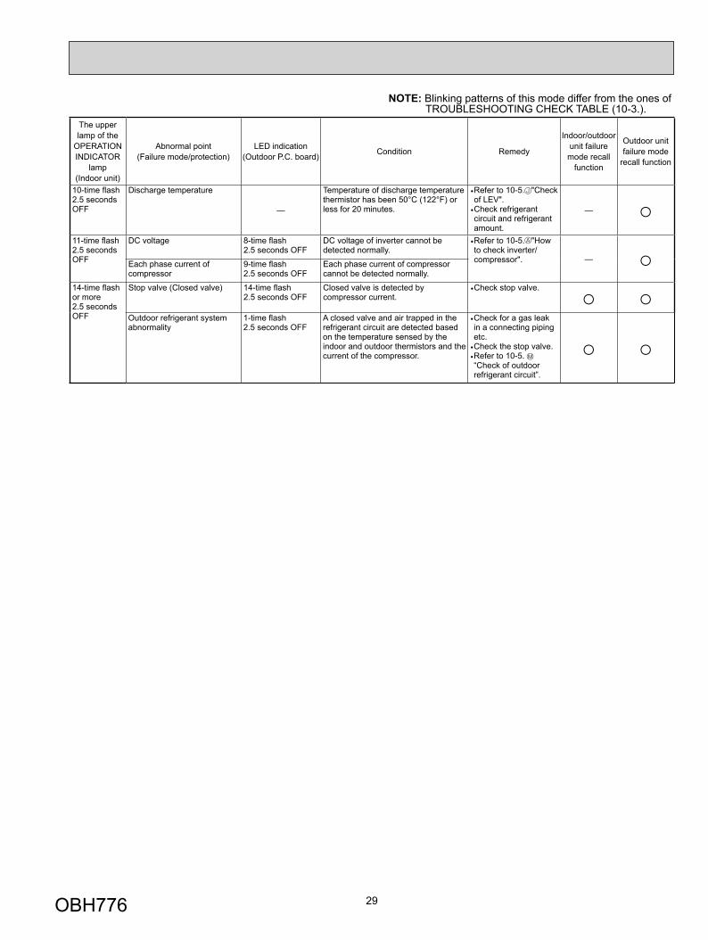
10-time fl ash 2.5 seconds OFF
Discharge temperature
—
Temperature of discharge temperature thermistor has been 50°C (122°F) or less for 20 minutes.
• Refer to 10-5. "Check of LEV".
• Check refrigerant circuit and refrigerant amount.
— ○11-time fl ash 2.5 seconds OFF
DC voltage 8-time fl ash 2.5 seconds OFF
DC voltage of inverter cannot be detected normally.
• Refer to 10-5. "How to check inverter/compressor". — ○Each phase current of
compressor 9-time fl ash 2.5 seconds OFF
Each phase current of compressor cannot be detected normally.
14-time fl ash or more2.5 seconds OFF
Stop valve (Closed valve) 14-time fl ash 2.5 seconds OFF
Closed valve is detected by compressor current.
• Check stop valve. ○ ○Outdoor refrigerant system abnormality
1-time fl ash 2.5 seconds OFF
A closed valve and air trapped in the refrigerant circuit are detected based on the temperature sensed by the indoor and outdoor thermistors and the current of the compressor.
• Check for a gas leak in a connecting piping etc.
• Check the stop valve.• Refer to 10-5. “Check of outdoor refrigerant circuit”.
○ ○
NOTE: Blinking patterns of this mode differ from the ones ofTROUBLESHOOTING CHECK TABLE (10-3.).
OBH776
30
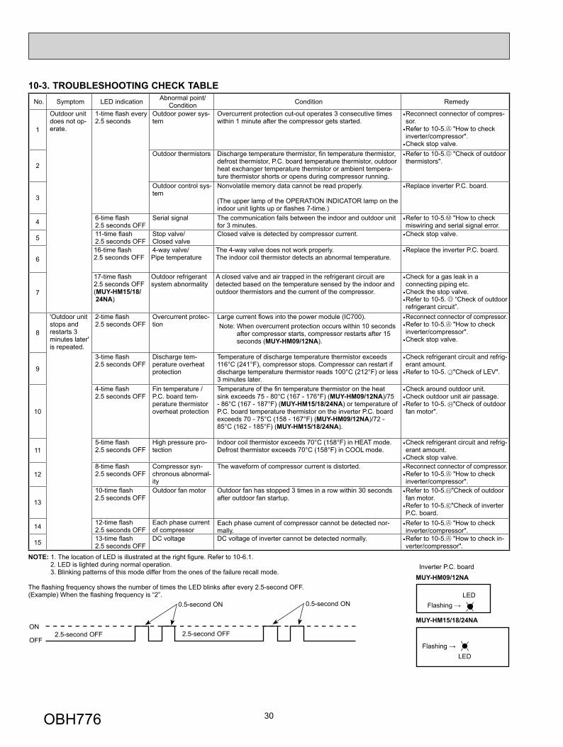
10-3. TROUBLESHOOTING CHECK TABLENo. Symptom LED indication Abnormal point/
Condition Condition Remedy
1
Outdoor unit does not op-erate.
1-time fl ash every 2.5 seconds
Outdoor power sys-tem
Overcurrent protection cut-out operates 3 consecutive times within 1 minute after the compressor gets started.
• Reconnect connector of compres-sor.
• Refer to 10-5. "How to check inverter/compressor".
• Check stop valve.
2
Outdoor thermistors Discharge temperature thermistor, fi n temperature thermistor, defrost thermistor, P.C. board temperature thermistor, outdoor heat exchanger temperature thermistor or ambient tempera-ture thermistor shorts or opens during compressor running.
• Refer to 10-5. "Check of outdoor thermistors".
3
Outdoor control sys-tem
Nonvolatile memory data cannot be read properly.
(The upper lamp of the OPERATION INDICATOR lamp on the indoor unit lights up or fl ashes 7-time.)
• Replace inverter P.C. board.
4 6-time fl ash 2.5 seconds OFF
Serial signal The communication fails between the indoor and outdoor unit for 3 minutes.
• Refer to 10-5. "How to check miswiring and serial signal error.
5 11-time fl ash 2.5 seconds OFF
Stop valve/ Closed valve
Closed valve is detected by compressor current. • Check stop valve.
616-time fl ash 2.5 seconds OFF
4-way valve/Pipe temperature
The 4-way valve does not work properly.The indoor coil thermistor detects an abnormal temperature.
• Replace the inverter P.C. board.
7
17-time fl ash 2.5 seconds OFF (MUY-HM15/18/ 24NA)
Outdoor refrigerant system abnormality
A closed valve and air trapped in the refrigerant circuit are detected based on the temperature sensed by the indoor and outdoor thermistors and the current of the compressor.
• Check for a gas leak in a connecting piping etc.
• Check the stop valve.• Refer to 10-5. “Check of outdoor refrigerant circuit”.
8
'Outdoor unit stops and restarts 3 minutes later' is repeated.
2-time fl ash 2.5 seconds OFF
Overcurrent protec-tion
Large current fl ows into the power module (IC700). Note: When overcurrent protection occurs within 10 seconds
after compressor starts, compressor restarts after 15 seconds (MUY-HM09/12NA).
• Reconnect connector of compressor.• Refer to 10-5. "How to check inverter/compressor".
• Check stop valve.
9
3-time fl ash 2.5 seconds OFF
Discharge tem-perature overheat protection
Temperature of discharge temperature thermistor exceeds 116°C (241°F), compressor stops. Compressor can restart if discharge temperature thermistor reads 100°C (212°F) or less 3 minutes later.
• Check refrigerant circuit and refrig-erant amount.
• Refer to 10-5. "Check of LEV".
10
4-time fl ash 2.5 seconds OFF
Fin temperature /P.C. board tem-perature thermistor overheat protection
Temperature of the fi n temperature thermistor on the heat sink exceeds 75 - 80°C (167 - 176°F) (MUY-HM09/12NA)/75 - 86°C (167 - 187°F) (MUY-HM15/18/24NA) or temperature of P.C. board temperature thermistor on the inverter P.C. board exceeds 70 - 75°C (158 - 167°F) (MUY-HM09/12NA)/72 - 85°C (162 - 185°F) (MUY-HM15/18/24NA).
• Check around outdoor unit.• Check outdoor unit air passage.• Refer to 10-5. "Check of outdoor fan motor".
115-time fl ash 2.5 seconds OFF
High pressure pro-tection
Indoor coil thermistor exceeds 70°C (158°F) in HEAT mode. Defrost thermistor exceeds 70°C (158°F) in COOL mode.
• Check refrigerant circuit and refrig-erant amount.
• Check stop valve.
128-time fl ash 2.5 seconds OFF
Compressor syn-chronous abnormal-ity
The waveform of compressor current is distorted. • Reconnect connector of compressor.• Refer to 10-5. "How to check inverter/compressor".
13
10-time fl ash 2.5 seconds OFF
Outdoor fan motor Outdoor fan has stopped 3 times in a row within 30 seconds after outdoor fan startup.
• Refer to 10-5. "Check of outdoor fan motor.
• Refer to 10-5. "Check of inverter P.C. board.
14 12-time fl ash 2.5 seconds OFF
Each phase current of compressor
Each phase current of compressor cannot be detected nor-mally.
• Refer to 10-5. "How to check inverter/compressor".
15 13-time fl ash 2.5 seconds OFF
DC voltage DC voltage of inverter cannot be detected normally. • Refer to 10-5. "How to check in-verter/compressor".
NOTE: 1. The location of LED is illustrated at the right fi gure. Refer to 10-6.1. 2. LED is lighted during normal operation. 3. Blinking patterns of this mode differ from the ones of the failure recall mode.
The fl ashing frequency shows the number of times the LED blinks after every 2.5-second OFF.(Example) When the fl ashing frequency is “2”.
ON
OFF2.5-second OFF 2.5-second OFF
0.5-second ON 0.5-second ON
LEDFlashing →
Inverter P.C. board
LEDFlashing →
MUY-HM09/12NA
MUY-HM15/18/24NA
OBH776
31
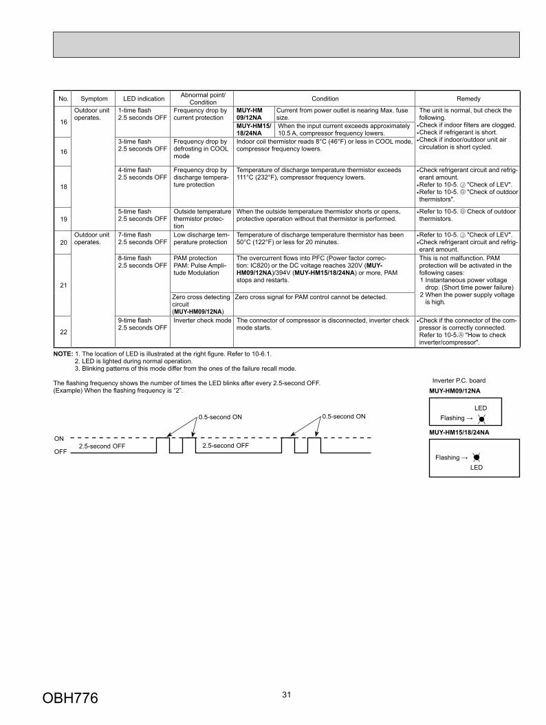
No. Symptom LED indication Abnormal point/ Condition Condition Remedy
16
Outdoor unit operates.
1-time fl ash 2.5 seconds OFF
Frequency drop by current protection
MUY-HM09/12NA
Current from power outlet is nearing Max. fuse size.
The unit is normal, but check the following.
• Check if indoor fi lters are clogged.• Check if refrigerant is short.• Check if indoor/outdoor unit air circulation is short cycled.
MUY-HM15/18/24NA
When the input current exceeds approximately 10.5 A, compressor frequency lowers.
163-time fl ash 2.5 seconds OFF
Frequency drop by defrosting in COOL mode
Indoor coil thermistor reads 8°C (46°F) or less in COOL mode, compressor frequency lowers.
18
4-time fl ash 2.5 seconds OFF
Frequency drop by discharge tempera-ture protection
Temperature of discharge temperature thermistor exceeds 111°C (232°F), compressor frequency lowers.
• Check refrigerant circuit and refrig-erant amount.
• Refer to 10-5. "Check of LEV".• Refer to 10-5. "Check of outdoor thermistors".
195-time fl ash 2.5 seconds OFF
Outside temperature thermistor protec-tion
When the outside temperature thermistor shorts or opens, protective operation without that thermistor is performed.
• Refer to 10-5. Check of outdoor thermistors.
20Outdoor unit operates.
7-time fl ash 2.5 seconds OFF
Low discharge tem-perature protection
Temperature of discharge temperature thermistor has been 50°C (122°F) or less for 20 minutes.
• Refer to 10-5. "Check of LEV".• Check refrigerant circuit and refrig-erant amount.
21
8-time fl ash 2.5 seconds OFF
PAM protection PAM: Pulse Ampli-tude Modulation
The overcurrent fl ows into PFC (Power factor correc-tion: IC820) or the DC voltage reaches 320V (MUY-HM09/12NA)/394V (MUY-HM15/18/24NA) or more, PAM stops and restarts.
This is not malfunction. PAM protection will be activated in the following cases:1 Instantaneous power voltage
drop. (Short time power failure)2 When the power supply voltage
is high. Zero cross detecting circuit (MUY-HM09/12NA)
Zero cross signal for PAM control cannot be detected.
22
9-time fl ash 2.5 seconds OFF
Inverter check mode The connector of compressor is disconnected, inverter check mode starts.
• Check if the connector of the com-pressor is correctly connected. Refer to 10-5. "How to check inverter/compressor".
NOTE: 1. The location of LED is illustrated at the right fi gure. Refer to 10-6.1. 2. LED is lighted during normal operation. 3. Blinking patterns of this mode differ from the ones of the failure recall mode.
The fl ashing frequency shows the number of times the LED blinks after every 2.5-second OFF.(Example) When the fl ashing frequency is “2”.
ON
OFF2.5-second OFF 2.5-second OFF
0.5-second ON 0.5-second ON
LEDFlashing →
Inverter P.C. board
LEDFlashing →
MUY-HM09/12NA
MUY-HM15/18/24NA
OBH776
32
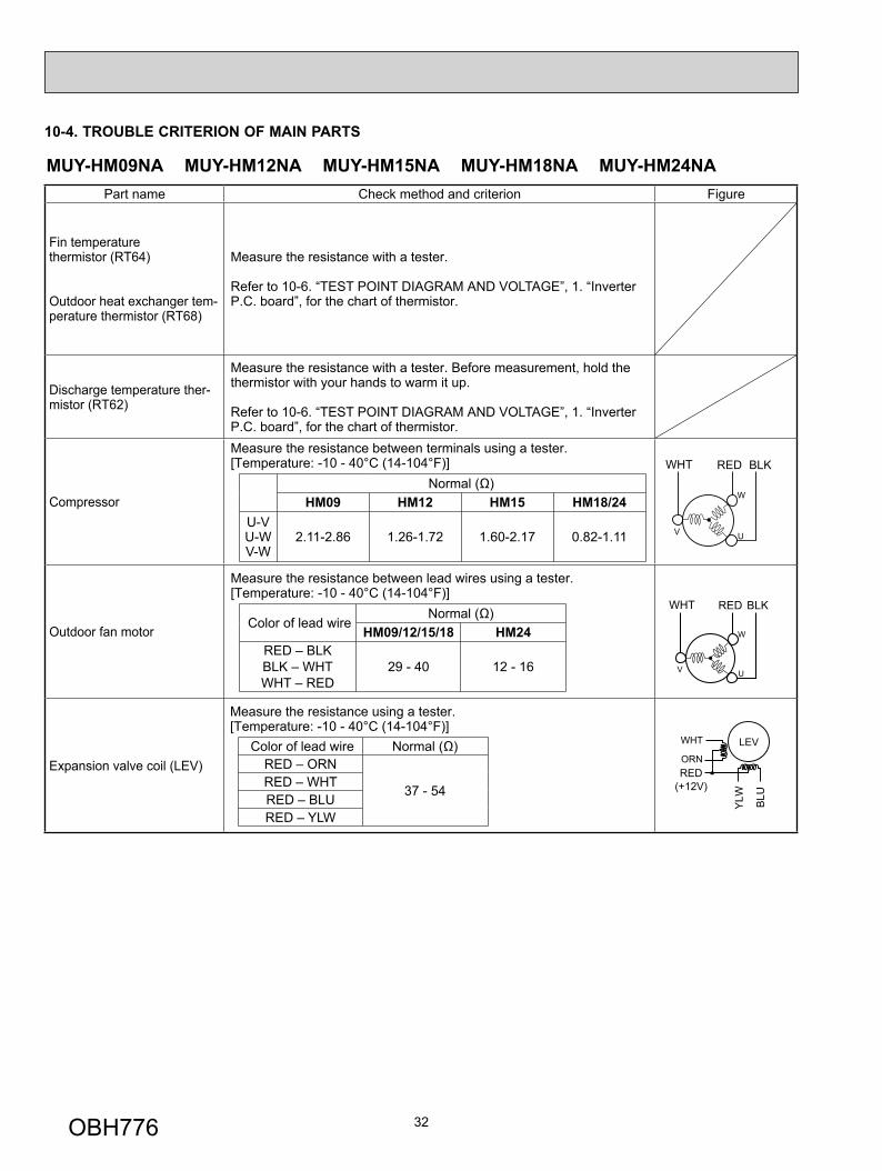
10-4. TROUBLE CRITERION OF MAIN PARTS
MUY-HM09NA MUY-HM12NA MUY-HM15NA MUY-HM18NA MUY-HM24NAPart name Check method and criterion Figure
Fin temperature thermistor (RT64)
Outdoor heat exchanger tem-perature thermistor (RT68)
Measure the resistance with a tester.
Refer to 10-6. “TEST POINT DIAGRAM AND VOLTAGE”, 1. “Inverter P.C. board”, for the chart of thermistor.
Discharge temperature ther-mistor (RT62)
Measure the resistance with a tester. Before measurement, hold the thermistor with your hands to warm it up.
Refer to 10-6. “TEST POINT DIAGRAM AND VOLTAGE”, 1. “Inverter P.C. board”, for the chart of thermistor.
Compressor
Measure the resistance between terminals using a tester.[Temperature: -10 - 40°C (14-104°F)]
Normal (Ω)HM09 HM12 HM15 HM18/24
U-VU-WV-W
2.11-2.86 1.26-1.72 1.60-2.17 0.82-1.11
W
UV
WHT RED BLK
Outdoor fan motor
Measure the resistance between lead wires using a tester.[Temperature: -10 - 40°C (14-104°F)]
Color of lead wire Normal (Ω)
HM09/12/15/18 HM24RED – BLKBLK – WHTWHT – RED
29 - 40 12 - 16
W
UV
WHT RED BLK
Expansion valve coil (LEV)
Measure the resistance using a tester. [Temperature: -10 - 40°C (14-104°F)]
Color of lead wire Normal (Ω)RED – ORN
37 - 54RED – WHTRED – BLURED – YLW
RED(+12V)
YLW BLU
WHT
ORN
LEV
OBH776
33
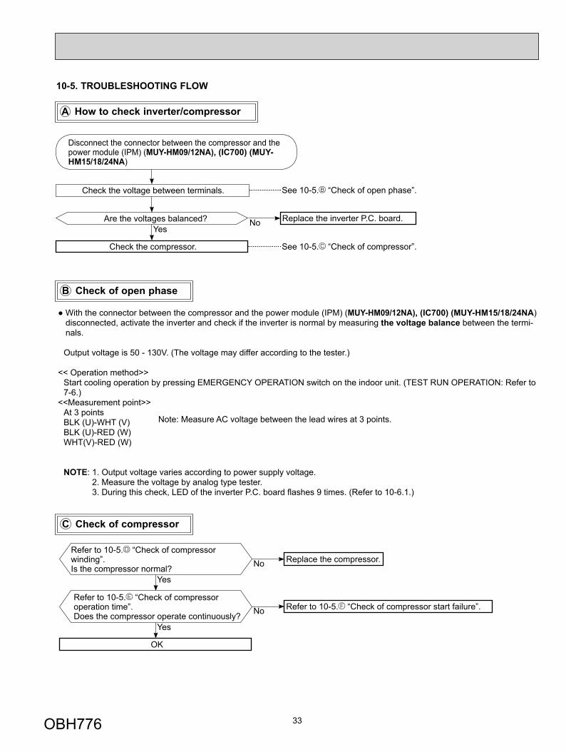
10-5. TROUBLESHOOTING FLOW
Are the voltages balanced?
Disconnect the connector between the compressor and the power module (IPM) (MUY-HM09/12NA), (IC700) (MUY-HM15/18/24NA)
Replace the inverter P.C. board.
Check the voltage between terminals.
Check the compressor. See 10-5. “Check of compressor”.
NoYes
See 10-5. “Check of open phase”.
A How to check inverter/compressor
Refer to 10-5. “Check of compressor operation time”.Does the compressor operate continuously?
Refer to 10-5. “Check of compressor start failure”.
OK
No
Yes
Refer to 10-5. “Check of compressor winding”.Is the compressor normal?
Replace the compressor.No
Yes
B Check of open phase
C Check of compressor
● With the connector between the compressor and the power module (IPM) (MUY-HM09/12NA), (IC700) (MUY-HM15/18/24NA) disconnected, activate the inverter and check if the inverter is normal by measuring the voltage balance between the termi-nals.
Output voltage is 50 - 130V. (The voltage may differ according to the tester.)
<< Operation method>> Start cooling operation by pressing EMERGENCY OPERATION switch on the indoor unit. (TEST RUN OPERATION: Refer to
7-6.)<<Measurement point>> At 3 points BLK (U)-WHT (V) BLK (U)-RED (W) WHT(V)-RED (W)
NOTE: 1. Output voltage varies according to power supply voltage. 2. Measure the voltage by analog type tester. 3. During this check, LED of the inverter P.C. board fl ashes 9 times. (Refer to 10-6.1.)
Note: Measure AC voltage between the lead wires at 3 points.
OBH776
34
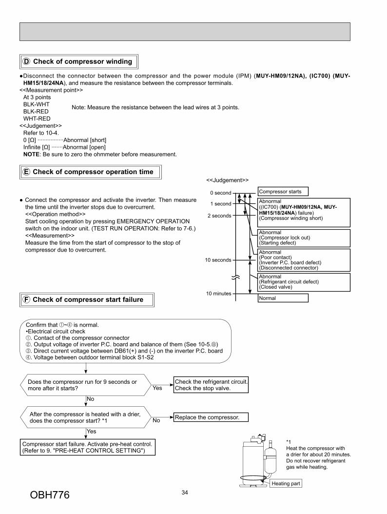
F Check of compressor start failure
D Check of compressor winding
E Check of compressor operation time
●Disconnect the connector between the compressor and the power module (IPM) (MUY-HM09/12NA), (IC700) (MUY-HM15/18/24NA), and measure the resistance between the compressor terminals.
<<Measurement point>> At 3 points BLK-WHT BLK-RED WHT-RED<<Judgement>> Refer to 10-4. 0 [Ω] ················Abnormal [short] Infinite [Ω] ·······Abnormal [open] NOTE: Be sure to zero the ohmmeter before measurement.
Note: Measure the resistance between the lead wires at 3 points.
After the compressor is heated with a drier, does the compressor start? *1 Replace the compressor.
Compressor start failure. Activate pre-heat control.(Refer to 9. "PRE-HEAT CONTROL SETTING")
No
Yes
Does the compressor run for 9 seconds or more after it starts?
Check the refrigerant circuit.Check the stop valve.Yes
No
*1Heat the compressor with a drier for about 20 minutes.Do not recover refrigerantgas while heating.
Heating part
● Connect the compressor and activate the inverter. Then measure the time until the inverter stops due to overcurrent.<<Operation method>>Start cooling operation by pressing EMERGENCY OPERATION switch on the indoor unit. (TEST RUN OPERATION: Refer to 7-6.)<<Measurement>>Measure the time from the start of compressor to the stop of compressor due to overcurrent.
Compressor starts
Abnormal((IC700) (MUY-HM09/12NA, MUY-HM15/18/24NA) failure)(Compressor winding short)
Abnormal(Compressor lock out)(Starting defect)
Abnormal(Poor contact)(Inverter P.C. board defect)(Disconnected connector)
Abnormal(Refrigerant circuit defect)(Closed valve)
Normal
0 second
1 second
2 seconds
10 seconds
10 minutes
<<Judgement>>
Confi rm that ~ is normal.•Electrical circuit check
. Contact of the compressor connector
. Output voltage of inverter P.C. board and balance of them (See 10-5. )
. Direct current voltage between DB61(+) and (-) on the inverter P.C. board
. Voltage between outdoor terminal block S1-S2
OBH776
35
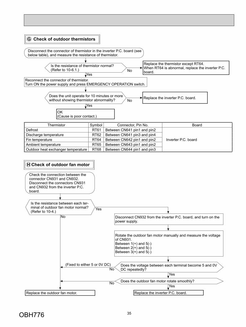
G Check of outdoor thermistors
Replace the thermistor except RT64.When RT64 is abnormal, replace the inverter P.C. board.
Replace the inverter P.C. board.
No
No
Is the resistance of thermistor normal? (Refer to 10-6.1.)
Reconnect the connector of thermistor.Turn ON the power supply and press EMERGENCY OPERATION switch.
Does the unit operate for 10 minutes or more without showing thermistor abnormality?
OK(Cause is poor contact.)
Yes
Yes
Disconnect the connector of thermistor in the inverter P.C. board (see below table), and measure the resistance of thermistor.
Thermistor Symbol Connector, Pin No. Board Defrost RT61 Between CN641 pin1 and pin2
Inverter P.C. boardDischarge temperature RT62 Between CN641 pin3 and pin4 Fin temperature RT64 Between CN642 pin1 and pin2 Ambient temperature RT65 Between CN643 pin1 and pin2 Outdoor heat exchanger temperature RT68 Between CN644 pin1 and pin3
H Check of outdoor fan motor
Is the resistance between each ter-minal of outdoor fan motor normal? (Refer to 10-4.)
Disconnect CN932 from the inverter P.C. board, and turn on the power supply.
Rotate the outdoor fan motor manually and measure the voltage of CN931.Between 1(+) and 5(-)Between 2(+) and 5(-)Between 3(+) and 5(-)
Does the voltage between each terminal become 5 and 0V DC repeatedly?
Does the outdoor fan motor rotate smoothly?
Replace the outdoor fan motor. Replace the inverter P.C. board.
Yes
Yes
No(Fixed to either 5 or 0V DC)
No
No
Yes
Check the connection between the connector CN931 and CN932.Disconnect the connectors CN931 and CN932 from the inverter P.C. board.
OBH776
36
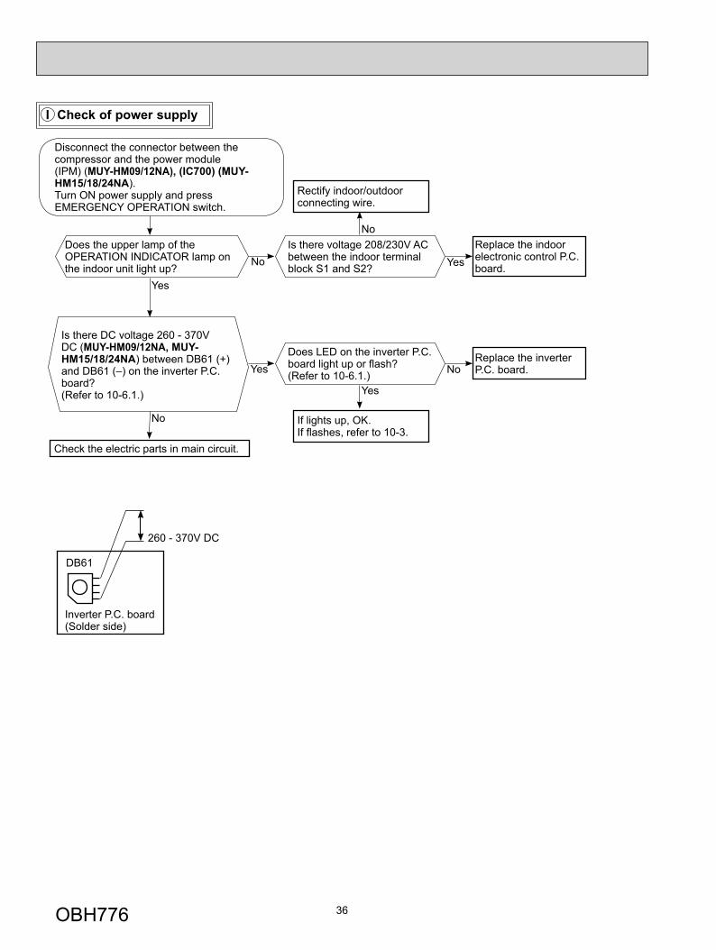
I Check of power supply
Is there voltage 208/230V AC between the indoor terminal block S1 and S2? Yes
NoReplace the indoor electronic control P.C. board.
Rectify indoor/outdoor connecting wire.
Yes
If lights up, OK.If fl ashes, refer to 10-3.
Does the upper lamp of the OPERATION INDICATOR lamp on the indoor unit light up?
Does LED on the inverter P.C. board light up or fl ash?(Refer to 10-6.1.) No
Replace the inverter P.C. board.
Is there DC voltage 260 - 370V DC (MUY-HM09/12NA, MUY-HM15/18/24NA) between DB61 (+) and DB61 (–) on the inverter P.C. board? (Refer to 10-6.1.)
No
Check the electric parts in main circuit.
Yes
Yes
No
Disconnect the connector between the compressor and the power module (IPM) (MUY-HM09/12NA), (IC700) (MUY-HM15/18/24NA).Turn ON power supply and pressEMERGENCY OPERATION switch.
Inverter P.C. board(Solder side)
DB61
260 - 370V DC
OBH776
37
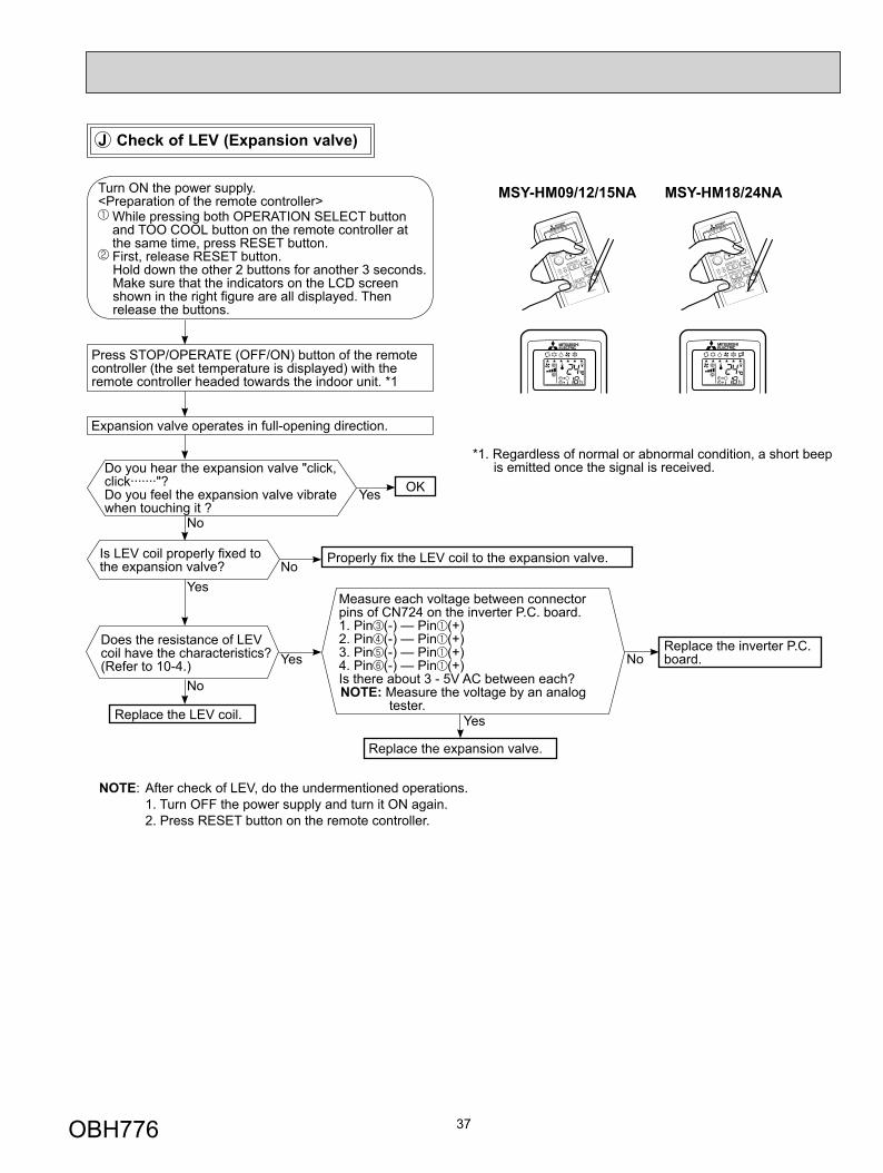
Press STOP/OPERATE (OFF/ON) button of the remote controller (the set temperature is displayed) with the remote controller headed towards the indoor unit. *1
Expansion valve operates in full-opening direction.
OK
NOTE: After check of LEV, do the undermentioned operations. 1. Turn OFF the power supply and turn it ON again. 2. Press RESET button on the remote controller.
*1. Regardless of normal or abnormal condition, a short beep is emitted once the signal is received.
Measure each voltage between connector pins of CN724 on the inverter P.C. board.1. Pin (-) — Pin (+)2. Pin (-) — Pin (+)3. Pin (-) — Pin (+)4. Pin (-) — Pin (+)Is there about 3 - 5V AC between each?NOTE: Measure the voltage by an analog
tester.
Properly fi x the LEV coil to the expansion valve.
Replace the inverter P.C. board.
Replace the LEV coil.
Replace the expansion valve.
Is LEV coil properly fi xed to the expansion valve?
Does the resistance of LEV coil have the characteristics?(Refer to 10-4.)
Do you hear the expansion valve "click, click·······"?Do you feel the expansion valve vibrate when touching it ?
Turn ON the power supply.<Preparation of the remote controller>
While pressing both OPERATION SELECT button and TOO COOL button on the remote controller at the same time, press RESET button. First, release RESET button. Hold down the other 2 buttons for another 3 seconds. Make sure that the indicators on the LCD screen shown in the right fi gure are all displayed. Then release the buttons.
Yes
No
No
Yes
NoYes
No
Yes
J Check of LEV (Expansion valve)
MSY-HM09/12/15NA MSY-HM18/24NA
OBH776
38
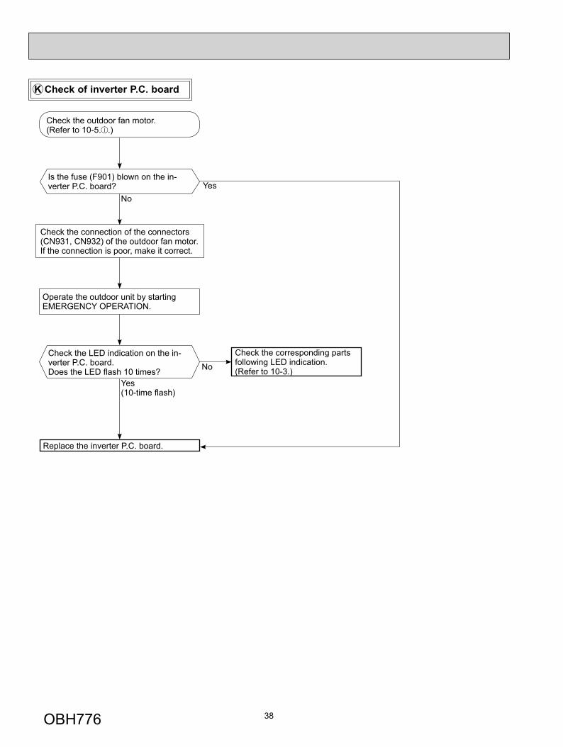
Check the outdoor fan motor. (Refer to 10-5. .)
Is the fuse (F901) blown on the in-verter P.C. board?
Check the connection of the connectors (CN931, CN932) of the outdoor fan motor. If the connection is poor, make it correct.
Operate the outdoor unit by starting EMERGENCY OPERATION.
Check the LED indication on the in-verter P.C. board.Does the LED fl ash 10 times?
Replace the inverter P.C. board.
Check the corresponding parts following LED indication.(Refer to 10-3.)
YesNo
Yes(10-time fl ash)
No
K Check of inverter P.C. board
OBH776
39
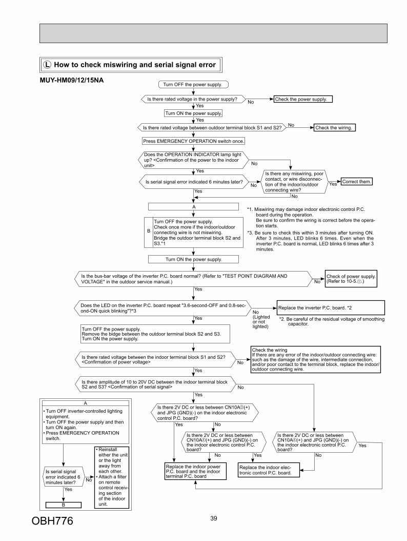
L How to check miswiring and serial signal error
• Turn OFF inverter-controlled lighting equipment.
• Turn OFF the power supply and then turn ON again.
• Press EMERGENCY OPERATION switch.
A
Is serial signal error indicated 6 minutes later?
B
Yes
• Reinstall either the unit or the light away from each other.
• Attach a fi lter on remote control receiv-ing section of the indoor unit.
No
Replace the indoor power P.C. board and the indoor terminal P.C. board
Turn OFF the power supply.
Is there rated voltage in the power supply?Yes
No
Turn ON the power supply.
Check the power supply.
Is there rated voltage between outdoor terminal block S1 and S2? No Check the wiring.
Press EMERGENCY OPERATION switch once.
Does the OPERATION INDICATOR lamp light up? <Confi rmation of the power to the indoor unit> No
Is serial signal error indicated 6 minutes later?
YesNo
Is there any miswiring, poor contact, or wire disconnec-tion of the indoor/outdoor connecting wire?
Yes Correct them.
No
A
Turn OFF the power supply.Check once more if the indoor/outdoor connecting wire is not miswiring.Bridge the outdoor terminal block S2 and S3.*1
B
*1. Miswiring may damage indoor electronic control P.C. board during the operation.Be sure to confi rm the wiring is correct before the opera-tion starts.
Turn ON the power supply.
Does the LED on the inverter P.C. board repeat "3.6-second-OFF and 0.8-sec-ond-ON quick blinking"?*3
YesNo(Lighted or not lighted)
Replace the inverter P.C. board. *2
*2. Be careful of the residual voltage of smoothing capacitor.
Is there amplitude of 10 to 20V DC between the indoor terminal block S2 and S3? <Confi rmation of serial signal>
Yes
Check the wiringIf there are any error of the indoor/outdoor connecting wire: such as the damage of the wire, intermediate connection, and/or poor contact to the terminal block, replace the indoor/outdoor connecting wire.
No
Is there 2V DC or less between CN10A (+) and JPG (GND)(-) on the indoor electronic control P.C. board?
NoYes
*3. Be sure to check this within 3 minutes after turning ON. After 3 minutes, LED blinks 6 times. Even when the inverter P.C. board is normal, LED blinks 6 times after 3 minutes.
Is there 2V DC or less between CN10A (+) and JPG (GND)(-) on the indoor electronic control P.C. board?
Is there 2V DC or less between CN10A (+) and JPG (GND)(-) on the indoor electronic control P.C. board?
Replace the indoor elec-tronic control P.C. board.
No Yes No
Yes
Is the bus-bar voltage of the inverter P.C. board normal? (Refer to "TEST POINT DIAGRAM AND VOLTAGE" in the outdoor service manual.) No
Yes
Check of power supply. (Refer to 10-5. .)
Turn OFF the power supply.Remove the bidge between the outdoor terminal block S2 and S3.Turn ON the power supply.
Is there rated voltage between the indoor terminal block S1 and S2? <Confi rmation of power voltage>
Yes
No
Yes
Yes
MUY-HM09/12/15NA
OBH776
40
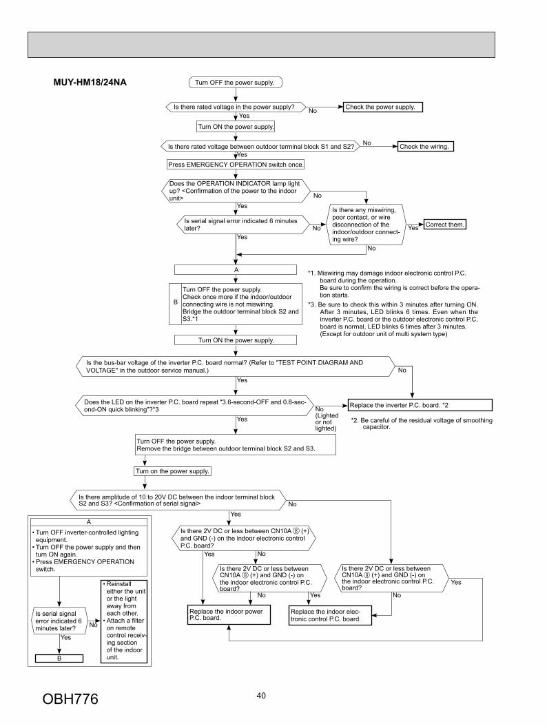
• Turn OFF inverter-controlled lighting equipment.
• Turn OFF the power supply and then turn ON again.
• Press EMERGENCY OPERATION switch.
A
Is serial signal error indicated 6 minutes later?
B
Yes
• Reinstall either the unit or the light away from each other.
• Attach a fi lter on remote control receiv-ing section of the indoor unit.
No
Turn OFF the power supply.
Is there rated voltage in the power supply?Yes
No
Turn ON the power supply.
Check the power supply.
Is there rated voltage between outdoor terminal block S1 and S2? No Check the wiring.
Press EMERGENCY OPERATION switch once.
Does the OPERATION INDICATOR lamp light up? <Confi rmation of the power to the indoor unit>
YesNo
Is serial signal error indicated 6 minutes later?
YesNo
Is there any miswiring, poor contact, or wire disconnection of the indoor/outdoor connect-ing wire?
Yes Correct them.
No
A
Turn OFF the power supply.Check once more if the indoor/outdoor connecting wire is not miswiring.Bridge the outdoor terminal block S2 and S3.*1
B
*1. Miswiring may damage indoor electronic control P.C. board during the operation.Be sure to confi rm the wiring is correct before the opera-tion starts.
Turn ON the power supply.
Does the LED on the inverter P.C. board repeat "3.6-second-OFF and 0.8-sec-ond-ON quick blinking"?*3
YesNo(Lighted or not lighted)
Replace the inverter P.C. board. *2
*2. Be careful of the residual voltage of smoothing capacitor.
Turn OFF the power supply.Remove the bridge between outdoor terminal block S2 and S3.
Yes
*3. Be sure to check this within 3 minutes after turning ON. After 3 minutes, LED blinks 6 times. Even when the inverter P.C. board or the outdoor electronic control P.C. board is normal, LED blinks 6 times after 3 minutes.
(Except for outdoor unit of multi system type)
Is the bus-bar voltage of the inverter P.C. board normal? (Refer to "TEST POINT DIAGRAM AND VOLTAGE" in the outdoor service manual.) No
Yes
Turn on the power supply.
Is there amplitude of 10 to 20V DC between the indoor terminal block S2 and S3? <Confi rmation of serial signal>
Yes
Is there 2V DC or less between CN10A (+) and GND (-) on the indoor electronic control P.C. board?
NoYes
Is there 2V DC or less between CN10A (+) and GND (-) on the indoor electronic control P.C. board?
Is there 2V DC or less between CN10A (+) and GND (-) on the indoor electronic control P.C. board?
Replace the indoor elec-tronic control P.C. board.
No Yes No
Yes
No
Replace the indoor power P.C. board.
MUY-HM18/24NA
OBH776
41
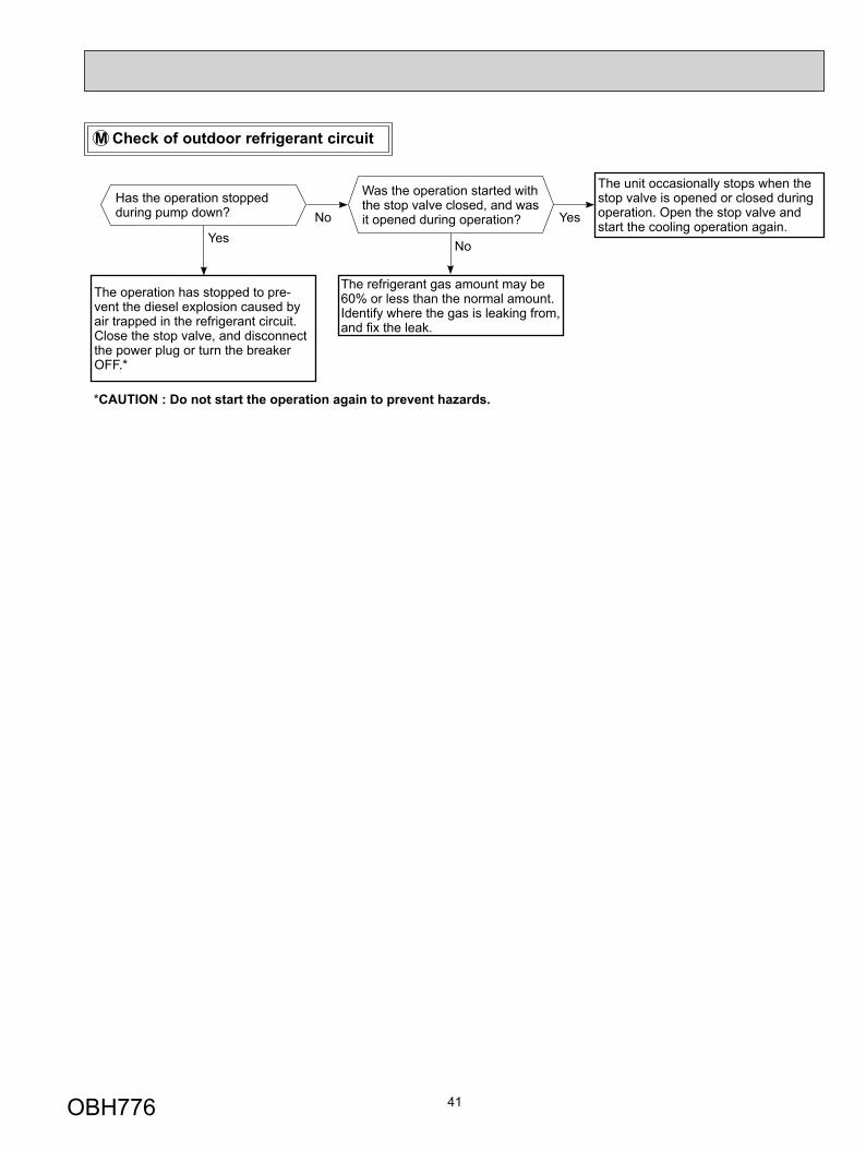
Has the operation stopped during pump down?
Was the operation started with the stop valve closed, and was it opened during operation?No
Yes
M Check of outdoor refrigerant circuit
The operation has stopped to pre-vent the diesel explosion caused by air trapped in the refrigerant circuit. Close the stop valve, and disconnect the power plug or turn the breaker OFF.*
The unit occasionally stops when the stop valve is opened or closed during operation. Open the stop valve and start the cooling operation again.
Yes
No
The refrigerant gas amount may be 60% or less than the normal amount. Identify where the gas is leaking from, and fi x the leak.
*CAUTION : Do not start the operation again to prevent hazards.
OBH776
42
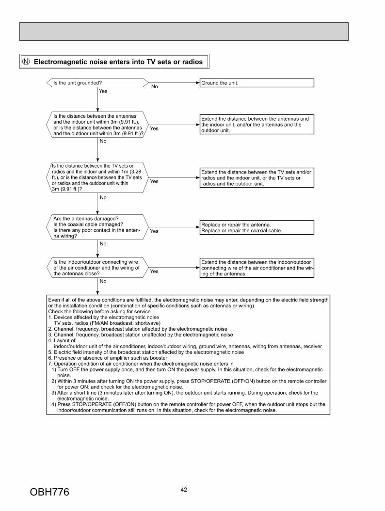
Electromagnetic noise enters into TV sets or radios
Is the unit grounded? Ground the unit.
Is the distance between the antennas and the indoor unit within 3m (9.91 ft.), or is the distance between the antennas and the outdoor unit within 3m (9.91 ft.)?
Extend the distance between the antennas and the indoor unit, and/or the antennas and the outdoor unit.
Is the distance between the TV sets or radios and the indoor unit within 1m (3.28 ft.), or is the distance between the TV sets or radios and the outdoor unit within 3m (9.91 ft.)?
Extend the distance between the TV sets and/or radios and the indoor unit, or the TV sets or radios and the outdoor unit.
Are the antennas damaged?Is the coaxial cable damaged?Is there any poor contact in the anten-na wiring?
No
Replace or repair the antenna.Replace or repair the coaxial cable.
Is the indoor/outdoor connecting wire of the air conditioner and the wiring of the antennas close?
Extend the distance between the indoor/outdoor connecting wire of the air conditioner and the wir-ing of the antennas.
Even if all of the above conditions are fulfi lled, the electromagnetic noise may enter, depending on the electric fi eld strength or the installation condition (combination of specifi c conditions such as antennas or wiring).Check the following before asking for service.1. Devices affected by the electromagnetic noise TV sets, radios (FM/AM broadcast, shortwave)2. Channel, frequency, broadcast station affected by the electromagnetic noise3. Channel, frequency, broadcast station unaffected by the electromagnetic noise4. Layout of: indoor/outdoor unit of the air conditioner, indoor/outdoor wiring, ground wire, antennas, wiring from antennas, receiver5. Electric fi eld intensity of the broadcast station affected by the electromagnetic noise6. Presence or absence of amplifi er such as booster7. Operation condition of air conditioner when the electromagnetic noise enters in
1) Turn OFF the power supply once, and then turn ON the power supply. In this situation, check for the electromagnetic noise.
2) Within 3 minutes after turning ON the power supply, press STOP/OPERATE (OFF/ON) button on the remote controller for power ON, and check for the electromagnetic noise.
3) After a short time (3 minutes later after turning ON), the outdoor unit starts running. During operation, check for the electromagnetic noise.
4) Press STOP/OPERATE (OFF/ON) button on the remote controller for power OFF, when the outdoor unit stops but the indoor/outdoor communication still runs on. In this situation, check for the electromagnetic noise.
No
No
No
NoYes
Yes
Yes
Yes
Yes
OBH776
43
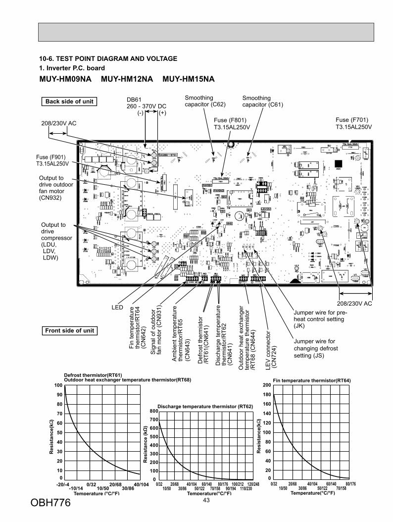
Fuse (F701)T3.15AL250V
208/230V AC
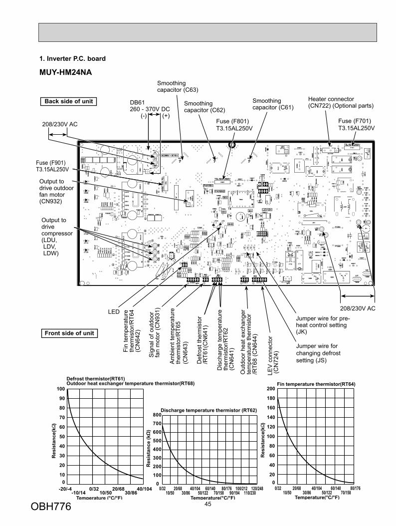
1. Inverter P.C. board10-6. TEST POINT DIAGRAM AND VOLTAGE
Fin
tem
pera
ture
ther
mis
tor/R
T64
(CN
642)
Am
bien
t tem
pera
ture
th
erm
isto
r/RT6
5(C
N64
3)
Dis
char
ge te
mpe
ratu
re
ther
mis
tor/R
T62
(CN
641)
Def
rost
ther
mis
tor
/RT6
1(C
N64
1)
DB61260 - 370V DC
Front side of unit
208/230V AC
Smoothing capacitor (C62)
Output to drivecompressor(LDU, LDV, LDW)
(+)(-)
Smoothing capacitor (C61)
Fuse (F901)T3.15AL250V
Jumper wire for changing defrost setting (JS)S
igna
l of o
utdo
orfa
n m
otor
(CN
931)
Out
door
hea
t exc
hang
erte
mpe
ratu
re th
erm
isto
r /R
T68
(CN
644)
Jumper wire for pre-heat control setting(JK)
Fuse (F801)T3.15AL250V
Back side of unit
LEV
con
nect
or (C
N72
4)
Output to drive outdoor fan motor(CN932)
LED
-20/-4-10/14
0/3210/50
20/6830/86
40/1040
10
20
30
40
50
60
70
80
90
100
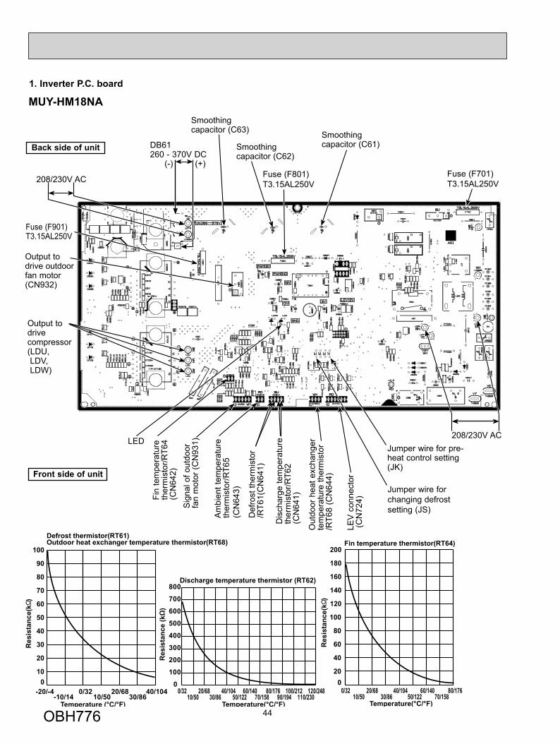
Defrost thermistor(RT61)Outdoor heat exchanger temperature thermistor(RT68)
020
40
60
80
100
120
140
160
180
200Fin temperature thermistor(RT64)
Res
ista
nce(
k )
Res
ista
nce(
k )
Discharge temperature thermistor (RT62)
Temperature (°C/°F) Temperature(°C/°F) Temperature(°C/°F)
0
100
200
300
400
500
600
700
800
0/3210/50
20/6830/86
40/10450/122
60/14070/158
80/17690/194
100/212110/230
120/248 0/3210/50
20/6830/86
40/10450/122
60/14070/158
80/176
MUY-HM09NA MUY-HM12NA MUY-HM15NA
OBH776
44
1. Inverter P.C. board
Fin
tem
pera
ture
ther
mis
tor/R
T64
(CN
642)
Am
bien
t tem
pera
ture
th
erm
isto
r/RT6
5(C
N64
3)
Dis
char
ge te
mpe
ratu
re
ther
mis
tor/R
T62
(CN
641)
Def
rost
ther
mis
tor
/RT6
1(C
N64
1)
DB61260 - 370V DC
Front side of unit
208/230V AC
Smoothing capacitor (C62)
Output to drivecompressor(LDU, LDV, LDW)
(+)(-)Fuse (F701)T3.15AL250V
Smoothing capacitor (C61)
Fuse (F901)T3.15AL250V
Jumper wire for changing defrost setting (JS)S
igna
l of o
utdo
orfa
n m
otor
(CN
931)
208/230V AC
Out
door
hea
t exc
hang
erte
mpe
ratu
re th
erm
isto
r /R
T68
(CN
644)
Jumper wire for pre-heat control setting(JK)
Fuse (F801)T3.15AL250V
Back side of unit
LEV
con
nect
or (C
N72
4)
Output to drive outdoor fan motor(CN932)
LED
-20/-4-10/14
0/3210/50
20/6830/86
40/1040
10
20
30
40
50
60
70
80
90
100
Defrost thermistor(RT61)Outdoor heat exchanger temperature thermistor(RT68)
020
40
60
80
100
120
140
160
180
200Fin temperature thermistor(RT64)
Res
ista
nce(
k )
Res
ista
nce(
k )
Discharge temperature thermistor (RT62)
Temperature (°C/°F) Temperature(°C/°F) Temperature(°C/°F)
0
100
200
300
400
500
600
700
800
0/3210/50
20/6830/86
40/10450/122
60/14070/158
80/17690/194
100/212110/230
120/248 0/3210/50
20/6830/86
40/10450/122
60/14070/158
80/176
Smoothing capacitor (C63)
MUY-HM18NA
OBH776
45
1. Inverter P.C. board
MUY-HM24NA
Front side of unit
Jumper wire for changing defrost setting (JS)
-20/-4-10/14
0/3210/50
20/6830/86
40/1040
10
20
30
40
50
60
70
80
90
100
Defrost thermistor(RT61)Outdoor heat exchanger temperature thermistor(RT68)
020
40
60
80
100
120
140
160
180
200Fin temperature thermistor(RT64)
Res
ista
nce(
k )
Res
ista
nce(
k )
Discharge temperature thermistor (RT62)
Temperature (°C/°F) Temperature(°C/°F) Temperature(°C/°F)
0
100
200
300
400
500
600
700
800
0/3210/50
20/6830/86
40/10450/122
60/14070/158
80/17690/194
100/212110/230
120/248 0/3210/50
20/6830/86
40/10450/122
60/14070/158
80/176
Fin
tem
pera
ture
ther
mis
tor/R
T64
(CN
642)
Am
bien
t tem
pera
ture
th
erm
isto
r/RT6
5(C
N64
3)
Dis
char
ge te
mpe
ratu
re
ther
mis
tor/R
T62
(CN
641)
Def
rost
ther
mis
tor
/RT6
1(C
N64
1)
DB61260 - 370V DC
208/230V AC
Smoothing capacitor (C62)
Output to drivecompressor(LDU, LDV, LDW)
(+)(-)Fuse (F701)T3.15AL250V
Smoothing capacitor (C61)
Fuse (F901)T3.15AL250V
Sig
nal o
f out
door
fan
mot
or (C
N93
1) 208/230V AC
Out
door
hea
t exc
hang
erte
mpe
ratu
re th
erm
isto
r /R
T68
(CN
644)
Jumper wire for pre-heat control setting(JK)
Heater connector(CN722) (Optional parts)
Fuse (F801)T3.15AL250V
Back side of unit
LEV
con
nect
or (C
N72
4)
Output to drive outdoor fan motor(CN932)
LED
Smoothing capacitor (C63)
OBH776
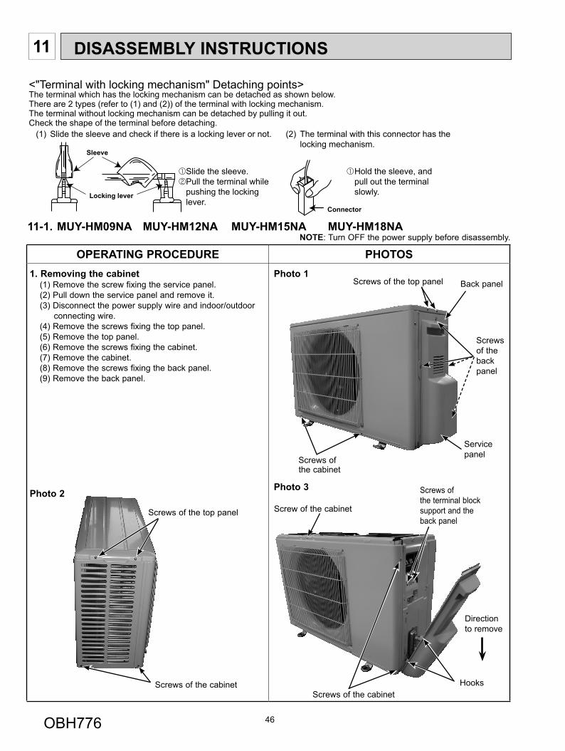
11-1. MUY-HM09NA MUY-HM12NA MUY-HM15NA MUY-HM18NANOTE: Turn OFF the power supply before disassembly.
OPERATING PROCEDURE PHOTOS1. Removing the cabinet
(1) Remove the screw fixing the service panel.(2) Pull down the service panel and remove it. (3) Disconnect the power supply wire and indoor/outdoor
connecting wire.(4) Remove the screws fixing the top panel.(5) Remove the top panel.(6) Remove the screws fixing the cabinet.(7) Remove the cabinet.(8) Remove the screws fixing the back panel.(9) Remove the back panel.
Photo 2
Photo 1
Photo 3
46
DISASSEMBLY INSTRUCTIONS11
(1) Slide the sleeve and check if there is a locking lever or not. (2) The terminal with this connector has the locking mechanism.
Slide the sleeve.Pull the terminal while pushing the lockinglever.
Hold the sleeve, and pull out the terminal slowly.
Connector
Sleeve
Locking lever
<"Terminal with locking mechanism" Detaching points>The terminal which has the locking mechanism can be detached as shown below.There are 2 types (refer to (1) and (2)) of the terminal with locking mechanism.The terminal without locking mechanism can be detached by pulling it out.Check the shape of the terminal before detaching.
Back panel
Service panel
Screws of the cabinet
Screws of the top panel
Direction to remove
Screws of the cabinetHooks
Screw of the cabinet
Screws of the back panel
Screws of the terminal block support and the back panel
Screws of the top panel
Screws of the cabinet
OBH776
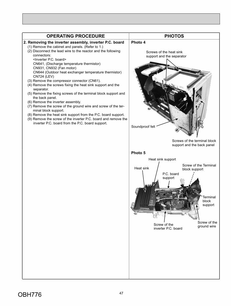
OPERATING PROCEDURE PHOTOS2. Removing the inverter assembly, inverter P.C. board
(1) Remove the cabinet and panels. (Refer to 1.)(2) Disconnect the lead wire to the reactor and the following
connectors: <Inverter P.C. board>
CN641, (Discharge temperature thermistor)CN931, CN932 (Fan motor)CN644 (Outdoor heat exchanger temperature thermistor)CN724 (LEV)
(3) Remove the compressor connector (CN61).(4) Remove the screws fixing the heat sink support and the
separator.(5) Remove the fixing screws of the terminal block support and
the back panel.(6) Remove the inverter assembly.(7) Remove the screw of the ground wire and screw of the ter-
minal block support.(8) Remove the heat sink support from the P.C. board support.(9) Remove the screw of the inverter P.C. board and remove the
inverter P.C. board from the P.C. board support.
Photo 4
Photo 5
47
Heat sink
Screw of the ground wire
Screw of the Terminal block support
Screw of the inverter P.C. board
Heat sink support
P.C. board support
Terminal block support
Screws of the heat sink support and the separator
Screws of the terminal block support and the back panel
Soundproof felt
OBH776
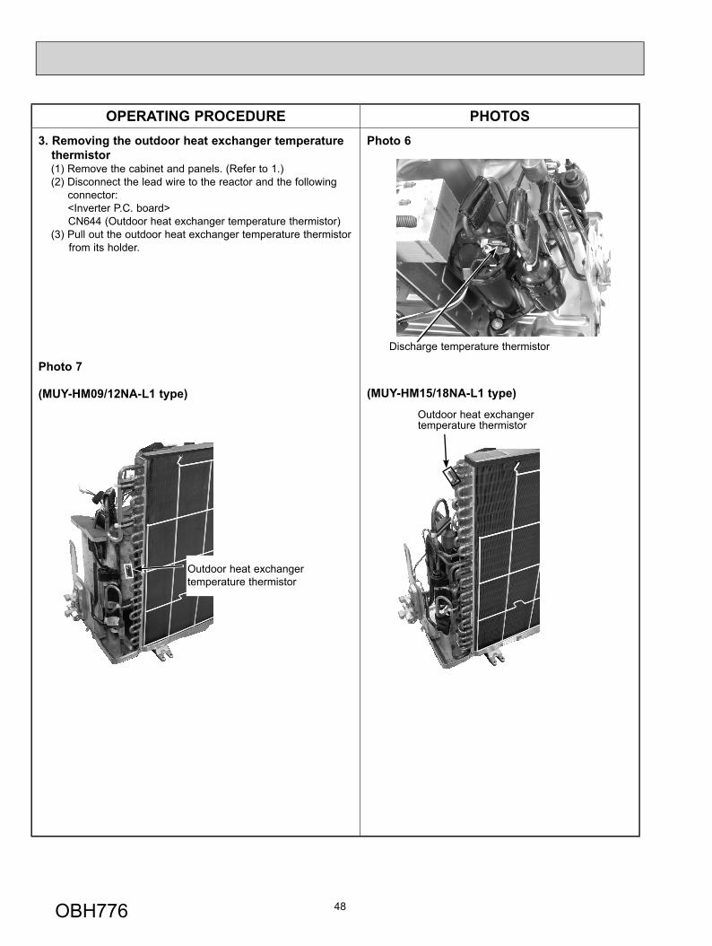
OPERATING PROCEDURE PHOTOS3. Removing the outdoor heat exchanger temperature
thermistor(1) Remove the cabinet and panels. (Refer to 1.)(2) Disconnect the lead wire to the reactor and the following
connector:<Inverter P.C. board>CN644 (Outdoor heat exchanger temperature thermistor)
(3) Pull out the outdoor heat exchanger temperature thermistor from its holder.
Photo 6
(MUY-HM15/18NA-L1 type)
Photo 7
(MUY-HM09/12NA-L1 type)Outdoor heat exchanger temperature thermistor
48
Discharge temperature thermistor
Outdoor heat exchanger temperature thermistor
OBH776
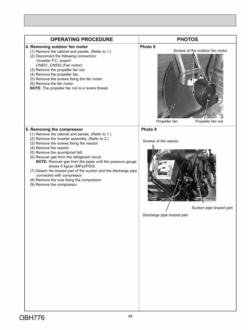
OPERATING PROCEDURE PHOTOS4. Removing outdoor fan motor
(1) Remove the cabinet and panels. (Refer to 1.)(2) Disconnect the following connectors: <Inverter P.C. board>
CN931, CN932 (Fan motor)(3) Remove the propeller fan nut.(4) Remove the propeller fan.(5) Remove the screws fixing the fan motor.(6) Remove the fan motor.NOTE: The propeller fan nut is a revers thread.
Photo 8
5. Removing the compressor(1) Remove the cabinet and panels. (Refer to 1.)(2) Remove the inverter assembly. (Refer to 2.)(3) Remove the screws fixing the reactor.(4) Remove the reactor.(5) Remove the soundproof felt.(6) Recover gas from the refrigerant circuit.
NOTE: Recover gas from the pipes until the pressure gauge shows 0 kg/ (MPa)/PSIG.
(7) Detach the brazed part of the suction and the discharge pipe connected with compressor.
(8) Remove the nuts fixing the compressor.(9) Remove the compressor.
Photo 9
49
Propeller fan nut
Screws of the outdoor fan motor
Propeller fan
Screws of the reactor
Suction pipe brazed part
Discharge pipe brazed part
OBH776
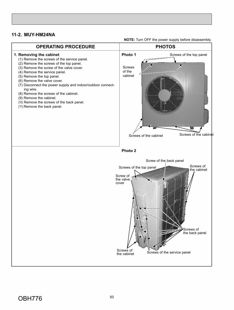
11-2. MUY-HM24NANOTE: Turn OFF the power supply before disassembly.
OPERATING PROCEDURE PHOTOS1. Removing the cabinet
(1) Remove the screws of the service panel.(2) Remove the screws of the top panel.(3) Remove the screw of the valve cover.(4) Remove the service panel.(5) Remove the top panel.(6) Remove the valve cover.(7) Disconnect the power supply and indoor/outdoor connect-
ing wire.(8) Remove the screws of the cabinet.(9) Remove the cabinet.(10) Remove the screws of the back panel.(11) Remove the back panel.
Photo 1
Photo 2
50
Screws of the cabinet
Screws of the top panel
Screws of the cabinet
Screws of the cabinet
Screws of the top panel
Screw of the back panel Screws of the cabinet
Screws of the service panel
Screw of the valve cover
Screws of the cabinet
Screws of the back panel
OBH776
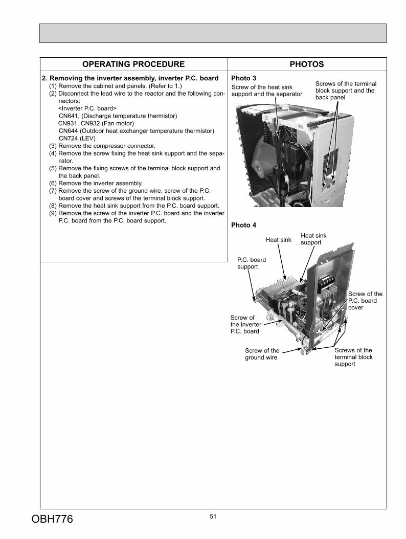
OPERATING PROCEDURE PHOTOS2. Removing the inverter assembly, inverter P.C. board
(1) Remove the cabinet and panels. (Refer to 1.)(2) Disconnect the lead wire to the reactor and the following con-
nectors:<Inverter P.C. board>CN641, (Discharge temperature thermistor)CN931, CN932 (Fan motor)CN644 (Outdoor heat exchanger temperature thermistor)CN724 (LEV)
(3) Remove the compressor connector.(4) Remove the screw fixing the heat sink support and the sepa-
rator.(5) Remove the fixing screws of the terminal block support and
the back panel.(6) Remove the inverter assembly.(7) Remove the screw of the ground wire, screw of the P.C.
board cover and screws of the terminal block support.(8) Remove the heat sink support from the P.C. board support.(9) Remove the screw of the inverter P.C. board and the inverter
P.C. board from the P.C. board support.
Photo 3
Photo 4
51
Screw of the heat sink support and the separator
Heat sink
Screw of the inverter P.C. board
Screw of the ground wire
Screws of the terminal block support
Screw of the P.C. board cover
Screws of the terminal block support and the back panel
P.C. board support
Heat sink support
OBH776
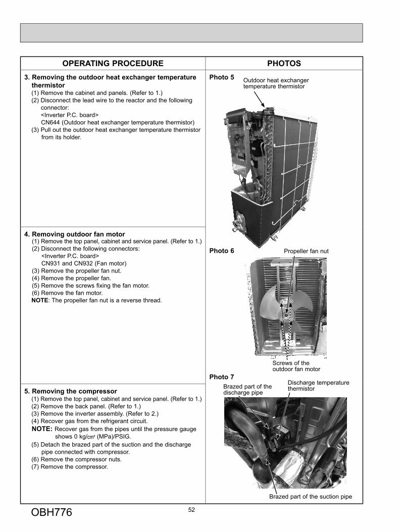
OPERATING PROCEDURE PHOTOS3. Removing the outdoor heat exchanger temperature
thermistor(1) Remove the cabinet and panels. (Refer to 1.)(2) Disconnect the lead wire to the reactor and the following
connector:<Inverter P.C. board>CN644 (Outdoor heat exchanger temperature thermistor)
(3) Pull out the outdoor heat exchanger temperature thermistor from its holder.
Photo 5
Photo 6
Photo 7
4. Removing outdoor fan motor(1) Remove the top panel, cabinet and service panel. (Refer to 1.)(2) Disconnect the following connectors:
<Inverter P.C. board>CN931 and CN932 (Fan motor)
(3) Remove the propeller fan nut.(4) Remove the propeller fan.(5) Remove the screws fixing the fan motor.(6) Remove the fan motor.NOTE: The propeller fan nut is a reverse thread.
5. Removing the compressor(1) Remove the top panel, cabinet and service panel. (Refer to 1.)(2) Remove the back panel. (Refer to 1.)(3) Remove the inverter assembly. (Refer to 2.)(4) Recover gas from the refrigerant circuit.NOTE: Recover gas from the pipes until the pressure gauge
shows 0 kg/ (MPa)/PSIG.(5) Detach the brazed part of the suction and the discharge
pipe connected with compressor.(6) Remove the compressor nuts.(7) Remove the compressor.
52
Screws of the outdoor fan motor
Brazed part of the discharge pipe
Brazed part of the suction pipe
Discharge temperature thermistor
Outdoor heat exchanger temperature thermistor
Propeller fan nut
OBH776

53OBH776

© Copyright 2017 MITSUBISHI ELECTRIC CORPORATIONPublished: Feb. 2017. No. OBH776Made in Japan
HEAD OFFICE: TOKYO BUILDING, 2-7-3, MARUNOUCHI, CHIYODA-KU, TOKYO 100-8310, JAPAN
Specifications are subject to change without notice.