hotembossing velten 4m semi nt 2974 tcm266-136302
TRANSCRIPT

Investigations on Reel-to-Reel Hot Embossing T. Velten, H. Schuck, W. Haberer, F. Bauerfeld Fraunhofer Institute for Biomedical Engineering (IBMT), 66386 St. Ingbert, Germany
Abstract Reel to reel processes like rotary hot embossing allow micro patterning of flexible foil based polymer substrates. Such technologies have the potential to be the basis for extremely cheap micro products. This is due to the low price for polymer foils as well as to the high throughput of reel-to-reel processes. An application field which could benefit of this technology is microfluidics. In this paper, a new type of reel-to-reel hot embossing machine will be presented. In contrast to commercially available reel-to-reel embossing machines the machine described here is capable doing continuous and discontinuous hot embossing. It is thus suited for fabrication of low, medium and high quantities of micro patterned polymer components. It has been investigated how parameters like foil temperature and feed rate will influence the quality of the embossed structures. First results of this investigation will be presented and discussed.
Keywords: hot embossing, reel-to-reel process, microfluidics, foil substrate
1. Introduction Nowadays, most microstructures are realised on rigid substrates like silicon, glass, ceramics, metals or polymers. Processes used for patterning include photolithography and etching to name just a few. The main disadvantage of the traditional technologies and equipment is the high price per micro machined surface area. An economic use of these technologies is only possible if the surface area per device is in the range of a few square millimetres. But there are many applications like e.g. microfluidic applications in the field of molecular diagnostics where lateral dimensions in the range of 100 µm and areas per device of about 2000 mm2 are typical values. Using conventional substrates and technologies would lead to very expensive devices. Replication technologies like injection moulding or hot embossing provide a cheap alternative and are suited for mass fabrication.
For microsystem applications the process of stamp hot embossing is well known. This process leads to very accurate replication even of structures in the sub-micron range. The most severe disadvantage of stamp hot embossing is the long cycle time associated with the heating and cooling phases, which is in the range of 10 minutes. Another drawback is the limited area which can be embossed per cycle. Even stamp embossing machines which according to literature are suited for large area replication are limited to an area of roughly 314 cm2 [1].
Using continuous reel-to-reel fabrication processes can reduce the cycle time drastically. This opens up new possibilities for very cheap patterning of polymer substrates. Rotary embossing of polymer foils in a reel-to-reel process is in principle a well-known process. But up to now, only a few attempts are known where this technique has been exploited for applications in the field of micro system technology [2]. An industrial application of reel-to-reel hot embossing is the fabrication of polymer foils for car interior lining. For this application the requirements for contour accuracy are rather low and the areas produced per year are huge.
Commercial rotary hot embossing is done in a continuous process. Each time the process is started it
takes some time until a thermal steady state is reached. A lot of waste is produced during the initial hot embossing phase before the steady state is reached. Here we describe a hot embossing machine capable doing discontinuous hot embossing in a rotary process which produces much less waste than a continuous process. 2. Materials and Methods
A new concept for a hot embossing machine has
been conceived and realised. In conventional reel-to-reel hot embossing machines (see Fig. 1) infrared light is used for heating up the foil substrate above the glass transition temperature before embossing. This makes the process very sensitive to any variation of the feed speed. If the speed is slightly too high the glass transition temperature will not be reached resulting in a poor embossing result. If the feed speed is slightly too low the foil will melt and will be torn apart. Usually hundreds of meters of foil have to pass the embossing machine until a steady state at the optimal embossing temperature is reached. This results in a high amount
Embossing roller
Counter roller
Spring
Foil
Infrared heater
Fig. 1. Principle of state of the art reel-to-reel hot embossing machines.
of waste. Such a process is not economic if one aims at fabricating microcomponents because in this case the waste might contain tens of thousands of micro-components. Such a wasteful process is especially not well suited for application fields where no mass production is needed.
We have conceived a hot embossing concept which overcomes these drawbacks (Fig. 2): a parallel pair of metal plates through which the foil is lead heats up the foil substrate. With this set-up an overheating of the foil is impossible because the foil temperature cannot be higher than the temperature of the metal plates. The reel-to-reel hot embossing is done in a discontinuous process, i.e. the foil feed is interrupted after the complete section of the foil which had rested between the metal plates has been embossed. During the standstill of the foil the part of the foil being between the metal plates is heated up slightly above the glass transition temperature. The length of the foil part between the two plates roughly corresponds to the circumference of the embossing roller which is about 470 mm.
Even if the described process is discontinuous it is a reel-to-reel process. This process produces minimal waste because the foil is not fed during the time when a thermal steady state is established.
Heated metal plates
Fig. 2. Principle of the reel-to-reel hot embossing machine for discontinuous embossing.
2.1. Influence of the metal plate temperature It is obvious from Fig. 2 that the foil heated up between the pair of metal plates will dissipate heat during moving along the gap between the pair of plates and the pair of rollers. Therefore the temperature of the heating plates should be well above the glass transition temperature to ensure that by reaching the pair of rollers the foil has not cooled down below the glass transition temperature. It is also clear that a too high temperature of the metal plates will result in corrugation or even melting of the part of the polymer foil which rests between the two plates. To find out the highest possible plate temperature the temperature had been increased stepwise until the foil got too much corrugated and began to stick to the plate. During the heating phase the foil feed rate was zero. The foil material used was polycarbonate (PC). This material has been used for all experiments described in this paper. The width of the PC foil was 195 mm for all experiments.
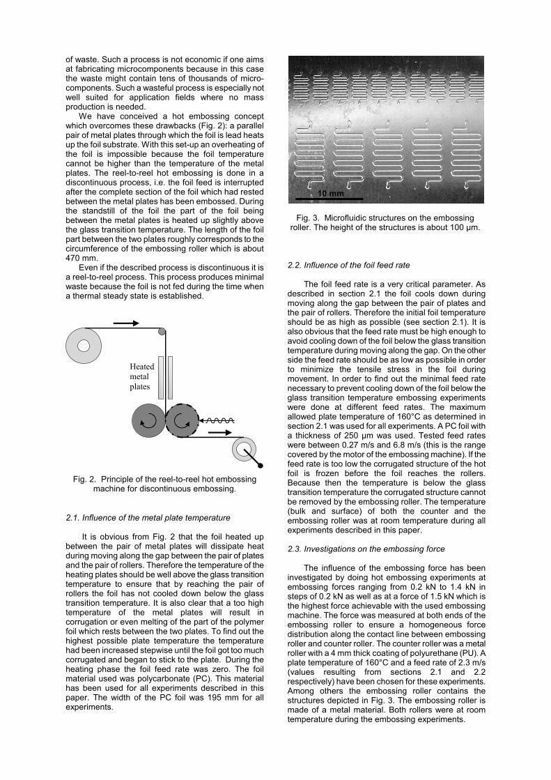
2.2. Influence of the foil feed rate The foil feed rate is a very critical parameter. As described in section 2.1 the foil cools down during moving along the gap between the pair of plates and the pair of rollers. Therefore the initial foil temperature should be as high as possible (see section 2.1). It is also obvious that the feed rate must be high enough to avoid cooling down of the foil below the glass transition temperature during moving along the gap. On the other side the feed rate should be as low as possible in order to minimize the tensile stress in the foil during movement. In order to find out the minimal feed rate necessary to prevent cooling down of the foil below the glass transition temperature embossing experiments were done at different feed rates. The maximum allowed plate temperature of 160°C as determined in section 2.1 was used for all experiments. A PC foil with a thickness of 250 µm was used. Tested feed rates were between 0.27 m/s and 6.8 m/s (this is the range covered by the motor of the embossing machine). If the feed rate is too low the corrugated structure of the hot foil is frozen before the foil reaches the rollers. Because then the temperature is below the glass transition temperature the corrugated structure cannot be removed by the embossing roller. The temperature (bulk and surface) of both the counter and the embossing roller was at room temperature during all experiments described in this paper. 2.3. Investigations on the embossing force The influence of the embossing force has been investigated by doing hot embossing experiments at embossing forces ranging from 0.2 kN to 1.4 kN in steps of 0.2 kN as well as at a force of 1.5 kN which is the highest force achievable with the used embossing machine. The force was measured at both ends of the embossing roller to ensure a homogeneous force distribution along the contact line between embossing roller and counter roller. The counter roller was a metal roller with a 4 mm thick coating of polyurethane (PU). A plate temperature of 160°C and a feed rate of 2.3 m/s (values resulting from sections 2.1 and 2.2 respectively) have been chosen for these experiments. Among others the embossing roller contains the structures depicted in Fig. 3. The embossing roller is made of a metal material. Both rollers were at room temperature during the embossing experiments.
Fig. 3. Microfluidic structures on the embossing
roller. The height of the structures is about 100 µm.
10 mm

2.4. Influence of the resting time between the hot plates While resting between the two hot plates the foil temperature is increasing and approaches the plate temperature. The finally reached temperature will depend on the time the foil rests between the hot plates. As the actual embossing time of the heated piece of foil is well below one second and thus can be neglected, the cycle time of the embossing process is roughly equal to the resting time. Short cycle times are preferred but too short resting time will result in too low foil temperatures. Resting times of 1, 2, 3, 4 and 5 minutes have been examined for a foil thickness of 500 µm, a plate temperature of 160°C, a feed rate of 2.3 m/s and an embossing force of 1.5 kN. 2.5. Effect of a steel counter roller Up to now a rather soft counter roller has been used for all experiments. To investigate the influence of the counter roller an embossing experiment with a steel counter roller was done for a foil thickness of 500 µm, a plate temperature of 160°C, a feed rate of 2.3 m/s, a resting time of 5 min and an embossing force of 1.5 kN. 3. Results 3.1. Influence of the metal plate temperature
The experiments described in section 2.1 revealed that up to a plate temperature of 160°C the foil did not stick to the hot plates. Above this temperature the foil corrugation was so high that the foil began to stick. In this case any feeding of the foil lead to a rupture of the foil.
3.2. Influence of the feed rate
The experiments described in section 2.2 showed that a minimum feed rate of about 2.3 m/s is necessary to assure that the 250 µm thick PC foil is above the glass transition temperature and can thus be embossed when reaching the embossing roller. The decision whether the corrugated structure is frozen or not could be easily taken just by looking at the foil after it has passed the embossing roller.
3.3. Influence of the embossing force
The characterisation of the embossed foils showed that the quality of the embossed structures is increasing with higher embossing forces. It could be clearly seen that low embossing forces lead to lower depths of the embossed meandered channel structures.
3.4. Influence of the rest time between the hot plates The correlation between the rest time and the depth of the embossed channels is shown in Table 1. The uncertainty of the measured structure depth is estimated to be about ±3 µm. A typical structure which resulted after a rest time of 5 min is shown in Fig. 4.
Table 1 Correlation between resting time and structure depth Resting time [min] Structure depth [µm] 1 80 2 90 3 92 4 95 5 95
3.5. Effect of a steel counter roller
If a hard steel counter roller is used instead of a soft PU roller the resulting embossed foil shows a macroscopic wave structure (see Fig. 5). Furthermore the depth of the embossed channel was about 5 µm less compared to the result of the experiment with a PU counter roller. Repeated experiments confirmed these findings.
Fig. 5. PC foil embossed with a steel counter roller. The foil shows a macroscopic wave structure which
was not present when using a soft PU roller.
4. Discussion By using the above-described embossing machine for hot embossing of foil substrates the foil is heated up between two hot metal plates and subsequently has to move along an air gap until it reaches the embossing calender. In order to avoid cooling down below the glass transition temperature during moving along the air gap the initial foil temperature should be as high as possible. Taking into account the results reported in
Wave structure
Fig. 4. Microfluidic channel embossed into a 500 µm thick PC foil. The resting time between the hot plates
before embossing was 5 min.

section 3.1 the highest possible temperature is 160°C. Above this temperature the foil begins to stick to the hot plates. This temperature can be regarded as the optimal plate temperature for embossing PC by the discontinuous embossing method. For this plate temperature the feed rate should be at least 2.3 m/s to avoid cooling down of the foil below the glass transition temperature during moving along the air gap. This is the value determined for a 250 µm thick foil. For thicker foils with a higher heat capacity at almost the same surface area a lower feed rate might be acceptable because dissipating the same amount of heat will result in lower temperature decrease. For thinner foils the opposite is true. Higher feed rates will lead to even higher embossing temperatures but, on the other hand, will increase the tensile stress in the foil and will thus increase the risk of tearing the foil apart.
During each embossing cycle the heated up piece of foil is embossed and a cold piece of foil is placed between the two hot plates for being heated up. According to the results listed in Table 1 it takes about 4-5 minutes until the 500 µm thick piece of PC foil has been heated up to the desired temperature. It is obvious that this time will decrease with decreasing foil thickness, because the heat capacity is proportional to foil thickness.
5. Conclusions
Several technologies for micro patterning of foil based polymer substrates are already available. Reel-to-reel hot embossing equipment for continuous hot embossing of structures in the meso range is commercially available. Economic use of this process is possible for very high volume production only. Stamp hot embossing equipment is also commercially available.
Within this work we reported on a new machine and method suited for discontinuous reel-to-reel hot embossing of polymer foils. In contrast to continuous processing the new discontinuous process produces almost no waste during the initial phase of the embossing. Thus the machine is well-suited for research and development or the prototyping phase of polymer micro components. The costs per patterned embossing roller are roughly 2000 Euro. This is not much more than costs for chromium masks used in photolithography.
The foil area which can be processed per time unit is at least 4 times higher than known from common stamp embossing machines. The cycle time is halved and the processed area per cycle more than doubled
compared to values reported in literature (e.g. [1]). It is emphasised that no structures below 10 µm have been embossed yet. Therefore a comparison with commercial hot embossing machines, which allow producing structures below 10 µm, should be limited to the structure sizes reported in this paper.
By increasing the dimensions of the two hot plates the processed area per cycle can be further increased without a need to increase the embossing force and practically without increasing the cycle time. Using a cascade of hot plates which stepwise increase the foil temperature will help to decrease the cycle time even further.
It should also be pointed out that the presented hot embossing machine is also well suited for continuous hot embossing. In this case the heating power of the hot plates has to be increased to a value which assures a foil temperature of 160°C when the foil moves out of the gap between the two hot plates.
During all experiments described in this paper the temperature of both the counter and the embossing roller was at room temperature. It is anticipated that varying the temperature of the rollers will influence the embossing results. Investigations on temperature influence are under way and the results will be described elsewhere. Acknowledgements
The authors would like to thank Torben Küster for his support in performing the hot embossing experiments. They would also like to thank the Fraunhofer-Gesellschaft for financially supporting the reported research.
Also, the writing of this paper was carried out within the framework of the EC Network of Excellence "Multi-Material Micro Manufacture: Technologies and Applications (4M)". References [1] M. Heckele et. al. Large area plastic replication with
modular molding tools. Proc. Second International Conference on Multi-Material Micro Manufacture, Grenoble, 20-22 September 2006, pp. 335-337.
[2] Michael Schuenemann et. al. Packaging of disposable chips for bioanalytical application. Electronic Components and Technology Conference, 2004, pp. 853-861.