icas 2012 flight testing of noise abating rnp procedures
TRANSCRIPT

28TH INTERNATIONAL CONGRESS OF THE AERONAUTICAL SCIENCES
1
Abstract
To test different types of noise abatement ap-proach procedures the Institute of Flight Guid-ance and the Institute of Aerodynamics and Flow Technology performed flight tests on the 6th September 2010 with a Boeing 737-700. In total 13 approaches to the Research Airport in Brunswick were flown while the approach area of the airport was equipped with six noise measurement microphones. Brunswick airport is equipped with an experimental ground based augmentation system (GBAS) which allows the implementation of 48 ILS lookalike precision approach procedures with different approach angles simultaneously.
1 Introduction
One of the major concerns regarding the ex-pected growth in air traffic is the increase of air pollution and the related climate change as well as the increase of noise especially in the vicinity of airports.
Actually there are two large research pro-grams in Europe which address this develop-ment. On the one hand it is the Joint Technolo-gy Initiative “Clean Sky JTI” [1] which will develop breakthrough technologies related to the aircraft itself to reduce environmental im-pact. On the other hand it is the Single Europe-an Sky ATM Research (SESAR) [2] program which is the technological and operational di-mension of the Single European Sky (SES). SESAR is trying to make flying more environ-mentally friendly from the air traffic manage-ment point of view. Both programs look for steep changes in air transport with major im-
provements but also with a relatively large time horizon.
Minor improvements can be reached al-ready nowadays by implementing new approach procedures that can be flown by many of to-day’s aircraft.
This paper describes the design of new ap-proach procedures for Frankfurt airport which were implemented at the research airport Brunswick and flight tested with a Boeing 737-700. The approach procedures consisted of steep approaches [3] with approach angles from 4.5° over 5° to 5.5° as well as of marginal steeper approaches with 3.2° approach angle instead of the widely use 3.0° as well as area navigation (RNAV) procedures and required navigation performance (RNP) procedures.
In order to fly the different approach angles under precision approach conditions the exper-imental ground based augmentation system (GBAS), which is in operation at the research airport Brunswick since 2009, delivered the necessary navigation performance. To guarantee the highest precision all the ap-proaches where flown in 0.10-nmi RNP mode.
2 Procedure Design
The RNAV procedures that have been validated in the flight trials have originally been devel-oped by the “forum flughafen und region” in cooperation with the German Air Navigation Service Provider Deutsche Flugsicherung GmbH (DFS) for the use at Frankfurt airport [4]. The procedures, which can be seen in Fig. 1 (green lines), are designed to avoid the dense-ly populated area of Offenbach, which lies un-der the extended centerlines (blue line) of the
FLIGHT TESTING OF NOISE ABATING RNP PROCE-DURES AND STEEP APPROACHES
Helmut H. Toebben*, Vilmar Mollwitz*, Lothar Bertsch**, Bernd Korn*, Dirk Kügler*
DLR German Aerospace Center, Institute of Flight Guidance*, Institute of Aerodynamics and Flow Technology**, Lilienthalplatz 7, 38108 Braunschweig
[email protected] Keywords: steep approach, curved approach, noise abatement procedures

Dr. Helmut H. Toebben
2
two main runways of Frankfurt (25L and 25R) at a distance of about 14km or 8NM from the threshold. The newly designed procedures will lead the aircraft around Offenbach in the south and onto the extended centerline at the waypoint OBERA. Here, the aircraft intercept the ILS-Approach at an altitude of 2000ft, about 1650ft above the thresholds. As these procedures should be evaluated at Braunschweig airport, they were transferred to Braunschweig as can be seen in Fig. 2 [5] [6] [7] [8] [9]. The distance and bearing from the threshold of Braunschweig runway 26 to the different waypoints are exactly the same as to the waypoints from Frankfurt’s runway 25L. Hence the transferred procedure looks exactly the same as the original one, only rotated to fit the different runway orientation at Braunschweig airport.
Fig. 1 Straight in (blue line) and RNAV (green lines) procedure for runway 25 in Frankfurt (EDDF)
Fig. 2 Straight in (blue line), RNAV (green lines) and RNP (red line) procedure for run-way 26 in Brunswick (EDVE)
Fig. 2 also shows a third procedure in the south leading from waypoint VE907 via VE906 and ENTSD to the runway. This procedure was added by DLR to investigate the feasibility of
RNP-approaches, where the aircraft is lead onto the extended centerline in a fixed-radius turn. When the aircraft intercepts the extended center-line, it has a height of just 1000ft above the threshold, while already descending on a con-stant flight path angle of 3°.
The three procedures can also be seen in detail in Fig. 3 and Fig. 4. The abovemen-tioned third procedure leads from VE906 to the waypoint ENTSD, which is the Final Approach Fix (FAF), but does not lie on the extended cen-terline. At ENTSD the aircraft will intercept at an altitude of 2000ft a glide slope of 3° leading constantly to the threshold of runway 26. Be-hind ENTSD, the aircraft - now in a constant descent of 3° - enters at VE905 a turn with a fixed radius of 2.0NM which ends at VE904 exactly on the extended centerline. At VE904 the height above threshold on the 3° glide slope is precisely 1000ft. From there, the aircraft con-tinues on the centerline and on the constant glide path to the runway, as on any ordinary ILS-approach.
Fig. 3 RNAV and RNP procedures for Brunswick (EDVE) in detail
Fig. 4 Fixed radius turn of RNP procedure for Brunswick (EDVE) in detail
The expected noise reduction through the avoidance of the dense populated areas of Of-fenbach can be seen in Fig. 5.

3
FLIGHT TESTING OF NOISE ABATING RNP PROCEDURES ANDSTEEP APPROACHES
a)
b)
c)
d)
Fig. 5 Comparison of awakenings per flight for the different scenarios based on a rough estimation of population density: a) estima-tion of the population density, b) affected people for a straight in, c) affected people for RNAV, d) affected people for RNP
Based on the Corinne Land Cover (CLC) data [10] for the Frankfurt area, a simplified scenario has been designed called Prankfurt. The land usage data allows a rough estimate of the popu-lation density similar to the Frankfurt area, Fig. 5 a). For this scenario, the aircraft noise induced awakenings [11] have been evaluated with DLR's noise prediction tool PANAM [12]. The prediction results for the Prankfurt scenario con-firm the expected noise dislocation effects. Fig. 5 b) shows the prediction for the straight in 3 degree approach to runway 25 L. Compared to this approach, the RNAV procedure results in a 16 % reduction in simulated awakenings for the Prankfurt scenario (Fig. 5 c)). The RNP proce-dure will even decrease this number by 40 %, as depicted in Fig. 5 d).
Besides the RNAV and RNP procedures also slightly steeper approaches with 3.2 degree approach angle on a 15 nm long straight final were tested that were also developed by the fo-rum flughafen und region in cooperation with the German Air Navigation Service Provider Deutsche Flugsicherung GmbH (DFS) for the
use at Frankfurt airport [13]. On top DLR tested steep approaches at 4.5, 5.0 and 5.5 degree on straight 15 nm long final.
3 Test
For the flight test and the noise measurements a Boeing 737-700 from Air Berlin was chartered performing 13 different approaches to the re-search airport in Brunswick. The aircraft was flown by Captain Marc Altenscheidt (chief pilot of the 737 fleet) and Captain Tim Techt (train-ing captain of the 737 fleet). The flight trials were conducted in a series of two legs.
Table 1 Test matrix 1st leg
Approach Transition
Final Approach Remarks
BWE – BWE
RNAV Ap-proach BSRVL
GLS 4.0° GPA Low Ap-proach
BWE – BWE
RNP Ap-proach BSHRY
ILS 3.5° GPA Low Ap-proach
BWE – BWE
RNAV Ap-proach BSHRY
GLS 4.0° GPA Low Ap-proach
BWE – BWE
Traffic Pat-tern 26, 15NM Final
GLS 3.0° GPA Low Ap-proach
BWE – BWE
Traffic Pat-tern 26, 15NM Final
GLS 3.2° GPA Low Ap-proach
BWE – BWE
Traffic Pat-tern 26, 15NM Final
GLS 4.5° GPA Low Ap-proach
BWE – BWE
Traffic Pat-tern 26, 15NM Final
GLS 5.0° GPA Low Ap-proach
BWE – BWE
Traffic Pat-tern 26, 15NM Final
GLS 5.5° GPA Low Ap-proach
The approach area was equipped with a set of 6 noise measurement microphones. The position of the microphones can be seen in Fig. 2. The two positions called “13034 straight in” and “13034 segmented” are located in a distance of 13034 meters to the runway threshold and cor-respond to a noise measurement point which also exists at Frankfurt airport and is located in the city center of Offenbach. The two points called “Fahrwerk I” and “Fahrwerk II” are lo-cated in an area where the gear should be down.
Dr. Helmut H. Toebben
4
The measurement point “BSOBR” is located at a point where the flaps setting should be final-ized. At the measurement point “1000 ft” the aircraft should be established on final approach especially after following the RNP route.
Table 2 Test matrix 2nd leg
Approach Transition
Final Approach Remarks
BWE – BWE
Traffic Pat-tern 26, 15NM Final
GLS 3.0° GPA Low Ap-proach
BWE – BWE
Traffic Pat-tern 26, 15NM Final
GLS 3.2° GPA Low Ap-proach
BWE – BWE
RNAV Ap-proach BSRVL
GLS 3.0° GPA Low Ap-proach
BWE – BWE
RNAV Ap-proach BSHRY
GLS 3.0° GPA Low Ap-proach
BWE – BWE
RNP Ap-proach BSHRY
ILS 3.5° GPA Low Ap-proach
4 Results
4.1 Precision
The precision with which the aircraft follows the predefined flight track is a crucial item in the Required Navigation Performance concept (RNP). As the name implies, RNP requires the aircraft to show navigational performance, i.e. precision, within a certain value, e.g. 0.3 nauti-cal miles (NM), which is then called RNP0.3. Accordant to the RNP concept, an RNP of for instance 0.05 NM means it is assured the air-craft is within a radius of 0.05 NM around the indicated position 95% of flight time. The on-board navigation systems of the aircraft con-stantly monitor the Actual Navigation Perfor-mance (ANP). Whenever the ANP is above the RNP, in this example worse than 0.3 NM, the procedure for which the certain RNP is required has to be aborted. The ANP itself is continually calculated on-board by the navigational systems depending on data availability and general as-sumptions about drift rates as well as data integ-rity under different circumstances. The men-tioned assumptions are based on experience
obtained during the certification process of a certain system used for navigation in the aircraft or general rules and formulae outlined in the certification guidelines.
0
0.01
0.02
0.03
0.04
0.05
0.06
0.07
0.08
0.09
0.1
0
1000
2000
3000
4000
5000
6000
7000
NavPerf-ANP
Altitude
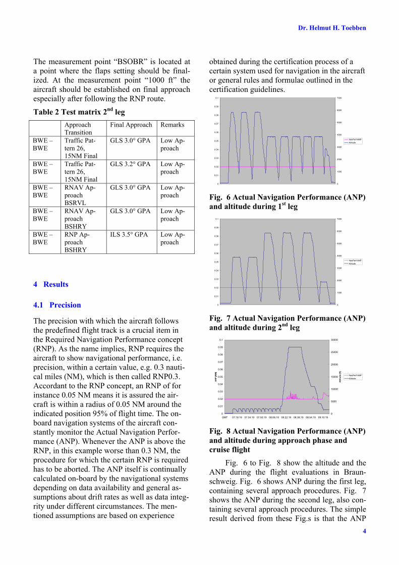
Fig. 6 Actual Navigation Performance (ANP) and altitude during 1st leg
0
0.01
0.02
0.03
0.04
0.05
0.06
0.07
0.08
0.09
0.1
0
1000
2000
3000
4000
5000
6000
7000
NavPerf-ANP
Altitude
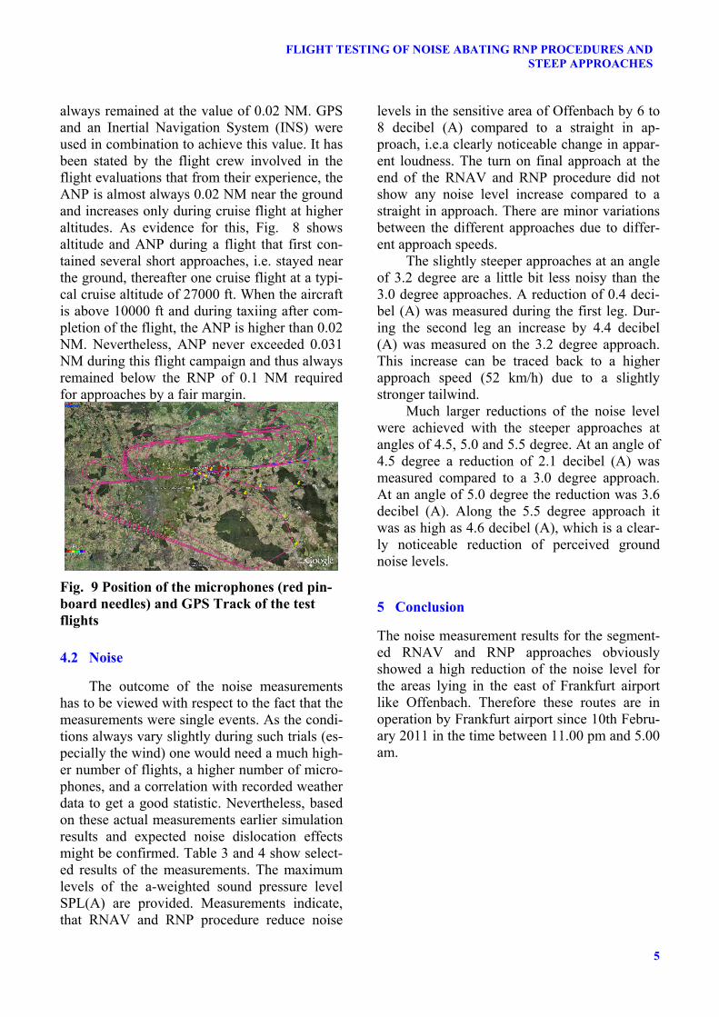
Fig. 7 Actual Navigation Performance (ANP) and altitude during 2nd leg
0
0.01
0.02
0.03
0.04
0.05
0.06
0.07
0.08
0.09
0.1
GMT 07:18:18 07:34:19 07:50:19 08:06:19 08:22:19 08:38:19 08:54:19 09:10:19
AN
P [
NM
]
0
5000
10000
15000
20000
25000
30000A
ltit
ud
e [
ft]
NavPerf-ANP
Altitude
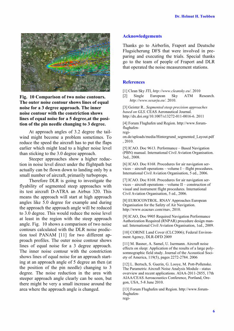
Fig. 8 Actual Navigation Performance (ANP) and altitude during approach phase and cruise flight
Fig. 6 to Fig. 8 show the altitude and the ANP during the flight evaluations in Braun-schweig. Fig. 6 shows ANP during the first leg, containing several approach procedures. Fig. 7 shows the ANP during the second leg, also con-taining several approach procedures. The simple result derived from these Fig.s is that the ANP
5
FLIGHT TESTING OF NOISE ABATING RNP PROCEDURES ANDSTEEP APPROACHES
always remained at the value of 0.02 NM. GPS and an Inertial Navigation System (INS) were used in combination to achieve this value. It has been stated by the flight crew involved in the flight evaluations that from their experience, the ANP is almost always 0.02 NM near the ground and increases only during cruise flight at higher altitudes. As evidence for this, Fig. 8 shows altitude and ANP during a flight that first con-tained several short approaches, i.e. stayed near the ground, thereafter one cruise flight at a typi-cal cruise altitude of 27000 ft. When the aircraft is above 10000 ft and during taxiing after com-pletion of the flight, the ANP is higher than 0.02 NM. Nevertheless, ANP never exceeded 0.031 NM during this flight campaign and thus always remained below the RNP of 0.1 NM required for approaches by a fair margin.
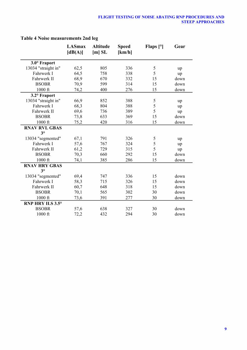
Fig. 9 Position of the microphones (red pin-board needles) and GPS Track of the test flights
4.2 Noise
The outcome of the noise measurements has to be viewed with respect to the fact that the measurements were single events. As the condi-tions always vary slightly during such trials (es-pecially the wind) one would need a much high-er number of flights, a higher number of micro-phones, and a correlation with recorded weather data to get a good statistic. Nevertheless, based on these actual measurements earlier simulation results and expected noise dislocation effects might be confirmed. Table 3 and 4 show select-ed results of the measurements. The maximum levels of the a-weighted sound pressure level SPL(A) are provided. Measurements indicate, that RNAV and RNP procedure reduce noise
levels in the sensitive area of Offenbach by 6 to 8 decibel (A) compared to a straight in ap-proach, i.e.a clearly noticeable change in appar-ent loudness. The turn on final approach at the end of the RNAV and RNP procedure did not show any noise level increase compared to a straight in approach. There are minor variations between the different approaches due to differ-ent approach speeds.
The slightly steeper approaches at an angle of 3.2 degree are a little bit less noisy than the 3.0 degree approaches. A reduction of 0.4 deci-bel (A) was measured during the first leg. Dur-ing the second leg an increase by 4.4 decibel (A) was measured on the 3.2 degree approach. This increase can be traced back to a higher approach speed (52 km/h) due to a slightly stronger tailwind.
Much larger reductions of the noise level were achieved with the steeper approaches at angles of 4.5, 5.0 and 5.5 degree. At an angle of 4.5 degree a reduction of 2.1 decibel (A) was measured compared to a 3.0 degree approach. At an angle of 5.0 degree the reduction was 3.6 decibel (A). Along the 5.5 degree approach it was as high as 4.6 decibel (A), which is a clear-ly noticeable reduction of perceived ground noise levels.
5 Conclusion
The noise measurement results for the segment-ed RNAV and RNP approaches obviously showed a high reduction of the noise level for the areas lying in the east of Frankfurt airport like Offenbach. Therefore these routes are in operation by Frankfurt airport since 10th Febru-ary 2011 in the time between 11.00 pm and 5.00 am.
Dr. Helmut H. Toebben
6
Fig. 10 Comparison of two noise contours. The outer noise contour shows lines of equal noise for a 3 degree approach. The inner noise contour with the constriction shows lines of equal noise for a 5 degree,at the posi-tion of the pin needle changing to 3 degree.
At approach angles of 3.2 degree the tail-wind might become a problem sometimes. To reduce the speed the aircraft has to put the flaps earlier which might lead to a higher noise level than sticking to the 3.0 degree approach.
Steeper approaches show a higher reduc-tion in noise level direct under the flightpath but actually can be flown down to landing only by a small number of aircraft, primarily turboprops.
Therefore DLR is going to investigate the flyability of segmented steep approaches with its test aircraft D-ATRA an Airbus 320. This means the approach will start at high approach angles like 5.0 degree for example and during the approach the approach angle will be reduced to 3.0 degree. This would reduce the noise level at least in the region with the steep approach angle. Fig. 10 shows a comparison of two noise contours calculated with the DLR noise predic-tion tool PANAM [11] for two different ap-proach profiles. The outer noise contour shows lines of equal noise for a 3 degree approach. The inner noise contour with the constriction shows lines of equal noise for an approach start-ing at an approach angle of 5 degree an then (at the position of the pin needle) changing to 3 degree. The noise reduction in the area with steeper approach angle clearly can be seen, but there might be very a small increase around the area where the approach angle is changed.
Acknowledgements
Thanks go to Airberlin, Fraport and Deutsche Flugsicherung DFS that were involved in pre-paring and executing the trials. Special thanks go to the team of people of Fraport and DLR that operated the noise measurement stations.
References
[1] Clean Sky JTI, http://www.cleansky.eu/. 2010 [2] Single European Sky ATM Research.
http://www.sesarju.eu/. 2010.
[3] Geister R.. Segmented steep precision approaches based on GLS. CEAS Aeronautical Journal. http://dx.doi.org/10.1007/s13272-011-0016-6. 2011
[4] Forum Flughafen und Region. http://www.forum-flughafen-regi-on.de/uploads/media/Hintergrund_segmented_Layout.pdf, 2010.
[5] ICAO. Doc 9613. Performance – Based Navigation (PBN) manual. International Civil Aviation Organisation. 3ed., 2008.
[6] ICAO. Doc 8168. Procedures for air navigation ser-vices – aircraft operations – volume I – flight procedures. International Civil Aviation Organisation, 5 ed., 2006.
[7] ICAO. Doc 8168. Procedures for air navigation ser-vices – aircraft operations – volume II – construction of visual and instrument flight procedures. International Civil Aviation Organisation, 5 ed., 2006.
[8] EUROCONTROL. RNAV Approaches European Organisation for the Safety of Air Navigation. http://www.ecacnav.com/rnav, 2010.
[9] ICAO, Doc 9905 Required Navigation Performance Authorization Required (RNPAR) procedure design man-ual. International Civil Aviation Organisation, 1ed., 2009.
[10] CORINE Land Cover (CLC2006); Federal Environ-ment Agency, DLR-DFD 2009
[11] M. Basner, A. Samel, U. Isermann. Aircraft noise effects on sleep: Application of the results of a large poly-somnographic field study. Journal of the Acoustical Soci-ety of America, 119(5), pages 2272-2784. 2006
[12] L. Bertsch, S. Guerin, G. Looye, M. Pott-Pollenske. The Parametric Aircraft Noise Analysis Module - status overview and recent applications. AIAA-2011-2855, 17th AIAA/CEAS Aeroacoustics Conference, Portland, Ore-gon, USA, 5-8 June 2010.
[13] Forum Flughafen und Region. http://www.forum-flughafen-regi-

7
FLIGHT TESTING OF NOISE ABATING RNP PROCEDURES ANDSTEEP APPROACHES
on.de/uploads/media/Hintergrund_erhoehter_Anfluggleitwinkel_3_2_Grad_Layout.pdf, 2010.
Copyright Statement
The authors confirm that they, and/or their company or organization, hold copyright on all of the original material included in this paper. The authors also confirm that they
have obtained permission, from the copyright holder of any third party material included in this paper, to publish it as part of their paper. The authors confirm that they give permission, or have obtained permission from the copyright holder of this paper, for the publication and distribution of this paper as part of the ICAS2012 pro-ceedings or as individual off-prints from the proceedings.

Dr. Helmut H. Toebben
8
Table 3 Noise measurements 1st leg
LASmax [dB(A)]
Altitude [m] SL
Speed [km/h]
Flaps [°] Gear
RNAV RVL GBAS 4°
13034 "segmented" 65,8 798 333 5 up Fahrwerk I no data Fahrwerk II 59,1 733 327 5 up
BSOBR 71,4 637 310 15 down 1000 ft 71,3 479 269 15 down
RNP HRY ILS 3.5° BSOBR 58,8 632 302 15 down 1000 ft 72,5 443 279 15 down
RNAV HRY GBAS 4°
13034 "segmented" 67,1 805 317 10 up Fahrwerk I 57 783 315 10 up Fahrwerk II 63,3 741 312 10 up
BSOBR 69,8 678 299 15 down 1000 ft 73,7 482 253 15 down
3.0° Fraport 13034 "straight in" 63 789 327 5 up LMP Fahrwerk I 65,4 744 330 5 up LMP Fahrwerk II 68,1 689 326 15 down
BSOBR 72,1 583 307 15 down 1000 ft 73,3 387 260 15 down
3.2° Fraport 13034 "straight in" 62,5 846 331 5 up
Fahrwerk I 64,1 794 334 5 up Fahrwerk II 68 733 337 5 up
BSOBR 71,6 626 312 15 down 1000 ft 73,8 417 266 15 down
GBAS 4.5° 13034 "straight in" 64,8 1124 264 40 down
Fahrwerk I 65,4 1049 263 40 down Fahrwerk II 64,8 972 260 40 down
BSOBR 65,5 839 259 40 down 1000 ft 70,7 536 250 40 down
GBAS 5.0° 13034 "straight in" 63,1 1225 276 30 down
Fahrwerk I 62,2 1194 268 40 down Fahrwerk II 65,3 1118 264 40 down
BSOBR 65,1 923 273 40 down 1000 ft 68,3 580 261 40 down
GBAS 5.5° 13034 "straight in" 62,3 1234 283 30 down
Fahrwerk I 62 1232 268 40 down Fahrwerk II 63,4 1180 259 40 down
BSOBR 64 1012 254 40 down 1000 ft 67,4 638 267 40 down
9
FLIGHT TESTING OF NOISE ABATING RNP PROCEDURES ANDSTEEP APPROACHES
Table 4 Noise measurements 2nd leg
LASmax [dB(A)]
Altitude [m] SL
Speed [km/h]
Flaps [°] Gear
3.0° Fraport 13034 "straight in" 62,5 805 336 5 up
Fahrwerk I 64,5 758 338 5 up Fahrwerk II 68,9 670 332 15 down
BSOBR 70,9 599 314 15 down 1000 ft 74,2 400 276 15 down
3.2° Fraport 13034 "straight in" 66,9 852 388 5 up
Fahrwerk I 68,3 804 388 5 up Fahrwerk II 69,6 736 389 5 up
BSOBR 73,8 633 369 15 down 1000 ft 75,2 420 316 15 down
RNAV RVL GBAS 3°
13034 "segmented" 67,1 791 326 5 up Fahrwerk I 57,6 767 324 5 up Fahrwerk II 61,2 729 315 5 up
BSOBR 70,3 660 292 15 down 1000 ft 74,1 385 286 15 down
RNAV HRY GBAS 3°
13034 "segmented" 69,4 747 336 15 down Fahrwerk I 58,3 715 326 15 down Fahrwerk II 60,7 648 318 15 down
BSOBR 70,1 565 302 30 down 1000 ft 73,6 391 277 30 down
RNP HRY ILS 3.5° BSOBR 57,6 638 327 30 down 1000 ft 72,2 432 294 30 down