implementation of image compression using …ijaerd.com/papers/finished_papers/implementation of...
TRANSCRIPT

International Journal of Advance Engineering and Research Development
Volume 2,Issue 6, June -2015
@IJAERD-2015, All rights Reserved 255
Scientific Journal of Impact Factor(SJIF): 3.134 e-ISSN(O): 2348-4470
p-ISSN(P): 2348-6406
IMPLEMENTATION OF IMAGE COMPRESSION USING SET
PARTITIONING HIERARCHICAL TREE USING HUFFMAN ENCODING
Ms. Nidhi Sodha1, Prof. Daxa V. Vekariya
2, Ms. Hiral R.Shah
3
1Computer Department, Noble Engineering College, Junagadh
2 Computer Department, Noble Engineering College, Junagadh,
3 Computer Department, Noble Engineering College, Junagadh,
Abstract — Image compression is an application of image processing performed on digital images. The main objective
of image compression is to reduce redundancy of the image data in order to be able to store or transmit data in an
efficient form. Image compression is a key technology in transmission and storage of digital images because of vast data
associated with them. Image compression is nothing but reducing the amount of data required to represent an image. To
compress an image efficiently we use various techniques to decrease the space and to increase the efficiency of transfer
of the images over network for better access. Here we use spiht (set partitioning in hierarchical trees) on the basis of
processing time, error comparison, mean square error, peak signal to noise ratio and compression ratio. Spiht gives
better simplicity and better compression compared to the other techniques. We proposed an image compression scheme
based on the set partitioning in hierarchical trees (spiht) algorithm using Huffman encoding techniques . we implement it
using metlab and in future work we are comparing it with other methods and comparing the final results in terms of psnr
and mse.
Keywords-image compression,
I. INTRODUCTION
An image is an artifact that records visual perception. Images are very important documents in today world
.digital images become popular for t ransferring visual information. There are many advantages to using these images
over traditional camera film images. The digital cameras produce instant images, which can be viewed without the delay
of wait ing for film processing. But these images are large in size. The compression techniques help to reduce the cost of
storage and efficient transmission of digital images. The main aim of image compression is to represent an image in the
fewest number of bits without losing the essential informat ion content within an orig inal image.
1.1 INTRODUCTION TO IMAGE COMPRESS ION:
Data compression is the technique to reduce the redundancies in data representation in order to decrease data
storage requirements and hence communication costs. Reducing the storage requirement is equivalent to increasing the
capacity of the storage medium and hence communication bandwidth. Thus the development of efficient compression
techniques will continue to be a design challenge for future communication systems and advanced mult imedia
applications. Data is represented as a combination of informat ion and redundancy. Information is the portion of data that
must be preserved permanently in its original form in order to correctly interpret the meaning or purpose of the data. A
technique to reduce the redundancy of data is defined as data compression.
The redundancy in data representation is reduced such a way that it can be subsequently reinserted to recover
the original data, which is called decompression of the data.
Figure 1.1:- Simple block diagram of image compression
Data compression can be understood as a method that takes an input data d and generates a shorter
representation of the data c(d) with less number of bits compared to that of d. The reverse process is called
decompression, which takes the compressed data c(d) and generates or reconstructs the data d‟ as shown in figure 1.1.
Somet imes the compression (coding) and decompression (decoding) systems together are called a “codec”.
1.2 TYPES OF IMAGE COMPRESS ION:
International Journal of Advance Engineering and Research Development (IJAERD)
Volume 2,Issue 6, June -2015, e-ISSN: 2348 - 4470 , print-ISSN:2348-6406
@IJAERD-2014, All rights Reserved 256
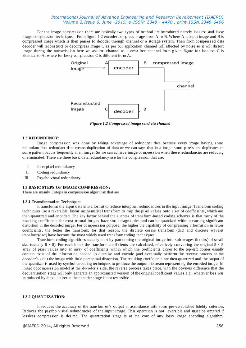
For the image compression there are basically two types of method are introduced namely lossless and lossy
image compression techniques. From figure 1.2 encoder compress image from A to B. Where A is input image and B is
compressed image which is then passes to decoder through channel or a storage system. Then from compressed data
decoder will reconstruct or decompress image C as per our application channel will affected by noise so it will distort
image during the transmission here we assume channel as a error-free channel from g iven figure fo r lossless C is
identical to A, where for lossy compression C is different from A.
Figure 1.2 Compressed image send via channel
1.3 REDUNDUNCY:
Image compression was done by taking advantage of redundant data because every image having some
redundant data redundant data means duplication of data or we can says that in a image some pixels are duplicates or
some pattern occurs frequently in an image. So we can achieve image compression when these redundancies are reducing
or eliminated. There are three basic data redundancy use for the compression that are:
I. Inter pixel redundancy
II. Coding redundancy
III. Psycho visual redundancy
1.3 BASIC STEPS OF IMAGE COMPRESSION:
There are mainly 3 steps in compression algorithm that are
1.3.1 Transformation Technique:
It transforms the input data into a format to reduce interpixel redundancies in the input image. Transform coding
techniques use a reversible, linear mathematical transform to map the pixel values onto a set of coefficients, which are
then quantized and encoded. The key factor behind the success of transform-based coding schemes is that many of the
resulting coefficients for most natural images have small magnitudes and can be quantized without causing significant
distortion in the decoded image. For compression purpose, the higher the capability of compressing informat ion in fewer
coefficients, the better the transform; for that reason, the discrete cosine transform (dct) and discrete wavelet
transform(dwt) have become the most widely used transform coding techniques.
Transform coding algorithms usually start by partitioning the original image into sub images (blocks) of s mall
size (usually 8 × 8). For each block the transform coefficients are calculated, effectively converting the original 8 × 8
array of pixel values into an array of coefficients within which the coefficients closer to the top -left corner usually
contain most of the information needed to quantize and encode (and eventually perform the reverse process at the
decoder’s side) the image with little perceptual distortion. The resulting coefficients are then quantized and the output of
the quantizer is used by symbol encoding techniques to produce the output bitstream representing the encoded image. In
image decompression model at the decoder’s side, the reverse process takes place, with the obvious difference that the
dequantization stage will only generate an approximated version of the original coefficient values e.g., whatever loss was
introduced by the quantizer in the encoder stage is not reversible.
1.3.2 QUANTIZATION:
It reduces the accuracy of the transformer’s output in accordance with some pre-established fidelity criterion.
Reduces the psycho visual redundancies of the input image. Th is operation is not eversible and must be omitted if
lossless compression is desired. The quantization stage is at the core of any lossy image encoding algorithm.

International Journal of Advance Engineering and Research Development (IJAERD)
Volume 2,Issue 6, June -2015, e-ISSN: 2348 - 4470 , print-ISSN:2348-6406
@IJAERD-2014, All rights Reserved 257
Quantizat ion at the encoder side, means partitioning of the input data range into a smaller set of values. There are two
main types of quantizers: scalar quantizers and vector quantizers. A scalar quantizer part itions the domain of input values
into a smaller number of intervals. If the output intervals are equally spaced, which is the simplest way to do it, the
process is called uniform scalar quantizat ion; otherwise, for reasons usually related to minimizat ion of total distortion, it
is called non uniform scalar quantization. One of the most popular non uniform quantizers is the lloyd -max quantizer.
Vector quantization (vq) techniques extend the basic princip les of scalar quantizat ion to multiple dimensions.
1.3.3. ENCODING:
It creates a fixed or variable-length code to represent the quantizer’s output and maps the output in accordance
with the code. In most cases, a variable -length code is used. An entropy encoder compresses the compressed values
obtained by the quantizer to provide more efficient compression. Most important types of entropy en coders used in lossy
image compression techniques are arithmetic encoder, Huffman encoder and run-length encoder.
Figure 1.3 Basic steps of image compression
II. OBJECTIVE
To compress image with higher compression ratio, better psnr and low mse. Reduce processing time also for
compression of images. Test the algorithm for images having different environmental conditions. Also algorithms are
applied on both gray image and color images. Compare and analysis the results using different parameter of compression
with other methods.
III. LITERATURE REVIEW
This paper addresses about various image compression techniques. On the basis of analyzing the various image
compression techniques this paper presents a survey of existing research papers. In this paper we analyze different types
of existing method of image compression. Compression of an image is significantly different then compression of binary
raw data. To solve these use different types of techniques for image compression. Now there is question ma y be arise that
how to image compress and which types of technique is used. For this purpose there are basically two types are method
are introduced namely lossless and lossy image compression techniques. In present time some other techniques are added
with basic method. In some area neural network genetic algorithms are used for image compression. [1]
.
In this paper it describes the discrete cosine transform (dct) technique for converting a signal into elementary
frequency components. It is widely used in image compression. Here they develop some simple functions to compute the
dct and to compress images. An image compression algorithm was comprehended using matlab code. The original image
is transformed in 8-by-8 blocks and then inverse transformed in 8-by-8 blocks to create the reconstructed image. The
inverse dct would be performed using the subset of dct coefficients. The erro r image (the difference between the original
and reconstructed image) would be d isplayed. Error value for every image would be calculated over various values of dct
co-efficients as selected by the user and would be displayed in the end to detect the accuracy and compression in the
resulting image and resulting performance parameter would be indicated in terms of mse , i.e . Mean square error. [2]
In this paper suggests a new image compression scheme with pruning proposal based on discrete wavelet
transformation (dwt). The effectiveness of the algorithm has been justified over some real images, and the performance
of the algorithm has been compared with other common compression standards. The algorithm has been implemented
using visual c++ and tested on a pentium core 2 duo 2.1 ghz pc with 1 gb ram. Experimental results demonstrate that the
proposed technique provides sufficient high compression ratios compared to other compression techniques. Wavelets are
better suited to time-limited data and wavelet based compression technique maintains better image quality by reducing
errors. It provide s better performance compared to other tradit ional techniques . [11]

International Journal of Advance Engineering and Research Development (IJAERD)
Volume 2,Issue 6, June -2015, e-ISSN: 2348 - 4470 , print-ISSN:2348-6406
@IJAERD-2014, All rights Reserved 258
IV. EXIS TING S YSTEM
4.1 ARCHITECTURE OF WAVELET
Wavelet compression involves a way analyzing an uncompressed image in a recursive. Fashion, resulting in a
series of higher resolution images, each “adding to” the information content in lower resolution images. The primary
steps in wavelet compression are performing a discrete wavelet t ransformat ion (dwt), quantization of the wavelet -space
image sub bands, and then encoding these sub bands. Wavelet images by and of themselves are not compressed images;
rather it is quantization and encoding stages that do the image compression and to store the compressed image. Wavelet
compression inherently results in a set of mult i-resolution images; it is well suited to working with large imagery which
needs to be selectively viewed at different resolution, as only the levels containing the required level of detail need to be
decompressed.
4.1.1 Decomposition process
The image is high and low-pass filtered along the rows. Results of each filter are down sampled by two. The two
sub-signals correspond to the high and low frequency components along the rows, each having a size n by n/2. Each of
the sub-signals is then again high and low-pass filtered, but now along the column data and the results are again down -
sampled by two.
Figure 4.1 One decomposition step of the two dimensional image
Figure 4.2 one dwt decomposition steps
The ll sub band obtained by low-pass filtering both the rows and columns, contains a rough description of the
image and hence called the approximation sub band. The hh sub band, high -pass filtered in both directions, contains the
high-frequency components along the diagonals. The hl and lh images result from low-pass filtering in one direction and
high pass filtering in the other direct ion. Lh contains mostly the vertical detail information , which corresponds to
horizontal edges. Hl represents the horizontal detail informat ion from the vertical edges. The sub bands hl, lh and hh are
called the detail sub bands since they add the high-frequency detail to the approximation image.
4.1.2 Composition process

International Journal of Advance Engineering and Research Development (IJAERD)
Volume 2,Issue 6, June -2015, e-ISSN: 2348 - 4470 , print-ISSN:2348-6406
@IJAERD-2014, All rights Reserved 259
Corresponds to the composition process. The four sub-images are up-sampled and Then filtered with the
corresponding inverse filters along the columns. The result of the last step is added together and the original image is
retrieved, with no information loss.
Figure 4.3 One composition step of the four sub images
4.2 SET PARTITIONING IN HIERARCHICAL TREES (SPIHT):
Spiht is the wavelet based image compression method. It provides the highest image Quality, progressive image
transmission, fully embedded coded file, simple quantization Algorithm, fast coding/decoding, completely adaptive,
lossless compression, and exact bit rate coding and error protection. Spiht makes use of three lists – the list of significant
pixels (lsp), list of insignificant pixels (lip) and list of insignificant sets (lis). These are coefficient location lists t hat
contain their coordinates. After the initialization, the algorithm takes two stages for each level of threshold – the sorting
pass (in which lists are organized) and the refinement pass (which does the actual progressive coding transmission). The
result is in the form of a bit stream. It is capable of recovering the image perfectly (every single b it of it) by coding all
bits of the transform. However, the wavelet transform yields perfect reconstruction only if its numbers are stored as
infinite imprecision numbers. Peak signal to noise ratio (psnr) is one of the quantitative measure for image quality
evaluation which is based on the mean square error (mse) o f the reconstructed image.
Figure 4.4:
Figure 4.4 Tree structure of spiht
4.2.1 SPIHT coding algorithm
Since the order in which the subsets are tested for significance is important in a practical implementation the
significance informat ion is stored in three ordered lists called list of insignificant sets (lis) list of insignificant pixels (lip)
and list of significant pixels (lsp). In all lists each entry is identified by a coordinate (i, j) which in the lip and lsp
represents individual pixels and in the lis represents either the set d (i, j) or l (i, j) . To differentiate between them it can
be concluded that a lis entry is of type a if it represents d(i,j) and of type b if it represents l(i, j). During the sorting pass

International Journal of Advance Engineering and Research Development (IJAERD)
Volume 2,Issue 6, June -2015, e-ISSN: 2348 - 4470 , print-ISSN:2348-6406
@IJAERD-2014, All rights Reserved 260
the pixels in the lip-which were insignificant in the previous pass -are tested and those that become significant are moved
to the lsp. Similarly, sets are sequentially evaluated following the lis order, and when a set is found to be significant it is
removed from the list and partitioned. The new subsets with more than one element are added back to the lis , while the
single coordinate sets are added to the end of the lip or the lsp depending whether they are insignificant or significant
respectively. The lsp contains the coordinates of the pixels that are visited in the refinement pass. Below the new
encoding algorithm in presented.
Figure 4.4 Block diagram of spiht
Algorithm
1. Init ialization: output n= |log2 (max (i, j) {c (i, j)}|; set the lsp as an empty list, and add the coordinates (i,j) € h t o the
lip, and only those with descendants also to the lis, as type a entries .
2. Sorting pass:
2.1 fo r each entry (i,j) in the lip do:
2.1.1 output sn (i,j)
2.1.2 if sn (i,j) then move (i,j) to the lsp and output the sign of c(i,j)
2.2 fo r each entry(i,j) in the lis do:
2.2.1 if the entry is of type a then
Output sn(d(i,j));
If sn(d(i,j)) then
For each (k,l) € o(i,j)do:
Output sn(k,l);
If sn(k,l) then add (k,l) to the lsp and output the sign of ck,l;
If sn (k,l) = 0 then add (k,l) to the end of the lip;
If l(i,j)≠0then move (i,j) to the end of the lis, as an entry of
Type b and go to step2.2.2 else, remove entry (i,j) from the
Lis;
2.2.2 if the entry is of type b then
Output sn(l(i,j));
If sn (l(i,j)) = 1 then
Add each (k,l) € o(i,j) to the end of the lis as an entry of type a;
Remove (i,j) from the lis.

International Journal of Advance Engineering and Research Development (IJAERD)
Volume 2,Issue 6, June -2015, e-ISSN: 2348 - 4470 , print-ISSN:2348-6406
@IJAERD-2014, All rights Reserved 261
3. Refinement pass for each entry (i,j) in the lsp, except those included in the last
Sorting pass (with same n), output the n-th most significant bit of |ci,j|;
4. Quantization-step update: decrement n by 1 and go to step 2.
Figure 4.5 spiht sorting pass
4.2.2 Advantages of spiht
The powerful wavelet-based image compression method called set partitioning in Hierarchical trees (spiht). The
spiht method is not a simple extension of traditional Methods for image compression, and represents an important
advance in the field. The method deserves special attention because it provides the following:
1) Highest image quality
2) Progressive image transmission
3) Fully embedded coded file
4) Simple quantization algorithm
5) fast coding/decoding
6) Completely adaptive
7) Lossless compression
8) Exact b it rate coding
9) Error protection
4.2.3 Example of spiht

International Journal of Advance Engineering and Research Development (IJAERD)
Volume 2,Issue 6, June -2015, e-ISSN: 2348 - 4470 , print-ISSN:2348-6406
@IJAERD-2014, All rights Reserved 262

International Journal of Advance Engineering and Research Development (IJAERD)
Volume 2,Issue 6, June -2015, e-ISSN: 2348 - 4470 , print-ISSN:2348-6406
@IJAERD-2014, All rights Reserved 263

International Journal of Advance Engineering and Research Development (IJAERD)
Volume 2,Issue 6, June -2015, e-ISSN: 2348 - 4470 , print-ISSN:2348-6406
@IJAERD-2014, All rights Reserved 264
4.3 Arithmetic coding
Arithmetic coding is a variable -length source encoding technique. In traditional entropy encoding techniques
such as Huffman coding, each input symbol in a message is substituted by a specific code specified by an integer number
of bits. Arithmetic coding deviates from this paradigm. In arithmetic coding a sequence of input symbols is represented
by an interval of real numbers between 0.0 and 1.0. The longer the message, the smaller the interval to represent the
message becomes. More probable symbols reduce the interval less than the less probable symbols and hence add fewer
bits in the encoded message. As a result, the coding result can reach to Shannon’s entropy limit for a sufficiently large
sequence of input symbols as long as the statistics are accurate. In arithmetic coding we make use of three registers
namely low, h igh and range[20]. Cumulat ive frequency is the defined as the cumulative counts of the symbol „i‟ . If
current interval is given by (low, high) then the values of range, low and high are calculated using the formula as given in
equation. Where cum_freq[i] represents the cumulative frequency of the symbol „i‟. For avoiding the under flowing of
registers and to reduce the coding latency a normalization procedure is used which is as follows:

International Journal of Advance Engineering and Research Development (IJAERD)
Volume 2,Issue 6, June -2015, e-ISSN: 2348 - 4470 , print-ISSN:2348-6406
@IJAERD-2014, All rights Reserved 265
1. If high < half, where half=0.5*2v then a „0‟ b it is written into output bit -stream.
2. If low ≥ half, then a „1‟ b it is written into output bit-stream.
3. Otherwise, an output bit is not defined. In this case a bit_to_follow counter is increased.
Then if condition 1 is satisfied then a „0‟ bit and bit_to_follows ones are written into output bit -stream. If condition 2 is
satisfied then a„1‟bit and bit_to_follows zeros are written into output bit -stream.
V. PROPOS ED S YS TEM
Image compression is an application of image processing performed on digital images. The main objective of
image compression is to reduce redundancy of the image data in order to be able to store or transmit data in an efficient
form. Generally a compression system consists of encoder and decoder stages. Encoder consists of the mapper, quantizer
and encoder. Mapper transforms the input image into a format by reducing the inter-pixel redundancies. Quantizing
refers to a reduction of the precision of the floating point values of the wavelet transform. A symbol encoder further
compresses the quantized values to give a better overall compression. It uses a model to accurately determine the
probabilit ies for each quantized value and produces an appropriate code based on these probabilit ies so that the resultant
output code stream will be smaller than the input stream. An arithmet ic coder or huffman coder is used as symbol
encoders. Decoder part of the compression model consists of symbol decoder and inverse mapper.
5.1 BLOCK DIAGRAM OF PROPOS ED S YS TEM
Figure 5.1 Block diagram of proposed system
5.2 Huffman coding
A method for the construction for minimum redundancy code. Huffman code is technique for compressing data.
Huffman made significant contributions in several areas. Mostly information theory and coding signal design for radar
and communication & design procedures for asynchronous logical circuits. Huffman coding is a form of statistical coding
which attempt to reduce the amounts of bits required representing the string of symbols to vary in length. Shorter codes
are assigned to the most frequently used symbols & longer codes to the symbol wh ich appear less frequently in the string.
Code word length is no longer fixed like ascii.
5.2.1 Algorithm and working of Huffman coding
1. Read a bmp image using image box control in Delphi language. The image control can be used to display a graphical
image-icon (ico), b itmap (bmp), metafile (wmf), gif, jpeg, etc. Th is control will read an image and convert them in a text
file.
2. Call a function that will sort or prioritize characters based on frequency count of each character in file.
3. Call a function that will create an in itial heap. Then reheap that tree according to occurrence of each node in the tree,
lower the occurrence earlier it is attached in heap. Create a new node where the left child is the lowest in the sorted list
and the right is the second lowest in the sorted list.
4. Build Huffman code tree based on prioritized list. Chop-off those two elements in the sorted list as they are now part
of one node and add the probabilit ies. The result is the probability for the new node.
5. Perform insertion sort on the list with the new node.

International Journal of Advance Engineering and Research Development (IJAERD)
Volume 2,Issue 6, June -2015, e-ISSN: 2348 - 4470 , print-ISSN:2348-6406
@IJAERD-2014, All rights Reserved 266
6. Repeat steps 3, 4, 5 until you only have 1 node left.
7. Perform a traversal o f tree to generate code table. This will determine code for each element of tree in the following
way. The code for each symbol may be obtained by tracing path to the symbol from the root of the tree. A 1 is assigned
for a b ranch in one direction and a 0 is assigned for branch in the other direction. For example a symbol which is reached
by branching right twice, then left once may be represented by the pattern ‗110„. The figure below depicts codes for
nodes of a sample tree.
/ \
(0) (1)
/ \
(10) (11)
/ \
(110) (111)
8. Once a Huffman tree is built, canonical Huffman codes, which require less information to rebuild, may be generated
by the following steps: step1. Remember the lengths of the codes resulting from a Huffman tree generated per above.
Step2. Sort the symbols to be encoded by the lengths of their codes (use symbol value to break ties). Step3. Init ialize the
current code to all zeros and assign code values to symbol from longest to shortest code as follows:
A. If the current code length is greater than the length of the code for the current symbol, right shift off the ext ra bits.
B. Assign the code to the current symbol.
C. Increment the code value.
D. Get the symbol with the next longest code.
E. Repeat from a until all symbols are assigned codes.
9. Encoding data-once a Huffman code has been generated, data may be encoded simply by replacing each symbol with
its code.
10. The original image is reconstructed i.e. Decompression is done by using Huffman decoding.
11. Generate a tree equivalent to the encoding tree. If you know the Huffman code for some encoded data, decoding may
be accomplished by reading the encoded data one bit at a time. Once the bits read match a code for symbol, write out the
symbol and start collecting bits again.
12. Read input character wise and left to the tree until last element is reached in the tree.
13. Output the character encodes in the leaf and returns to the root, and continues the step 12, until all the codes of
corresponding symbols is known.
V. Implementation and Result
Here we implement our propose method using MATLAB version 13.0 .MATLAB is a high - level technical
computing language and interactive environment for algorithm development, data visualizat ion, data analysis, and
numeric computation. MATLAB product is used to solve technical computing problems faster than with traditional
programming languages, such as C, C++, and FORTRAN.
Below figure shows the test image that we have used for the testing of system. This benchmark image is taken
from http://www.imagecompression.info/ where images are available in 8 b it , 16 bit, 24 bit and available for both gray
and RGB image. Dimensions for image are 512×512 and size is 774KB.

International Journal of Advance Engineering and Research Development (IJAERD)
Volume 2,Issue 6, June -2015, e-ISSN: 2348 - 4470 , print-ISSN:2348-6406
@IJAERD-2014, All rights Reserved 267
Figure 6.1 Original image Figure 6.2 Image after applying dwt
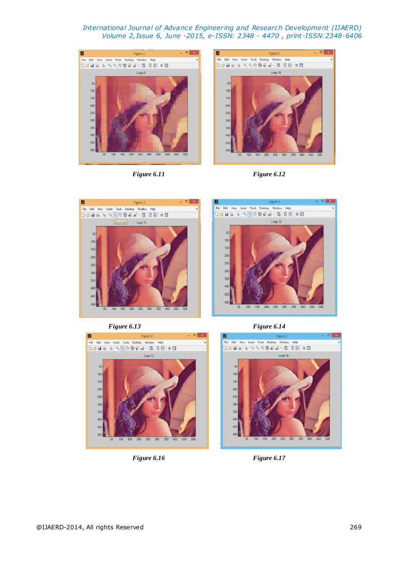
6.2 RES ULT OF PROPOS ED METHOD:
In the result of the proposed method each value of threshold we get the compressed image and for each value of
threshold output images are as shown in given below (From figure 6.3 to 6.19).
Figure 6.3 Figure 6.4

International Journal of Advance Engineering and Research Development (IJAERD)
Volume 2,Issue 6, June -2015, e-ISSN: 2348 - 4470 , print-ISSN:2348-6406
@IJAERD-2014, All rights Reserved 268
Figure 6.5 Figure 6.6
Figure 6.7 Figure 6.8
Figure 6.9 Figure 6.10
International Journal of Advance Engineering and Research Development (IJAERD)
Volume 2,Issue 6, June -2015, e-ISSN: 2348 - 4470 , print-ISSN:2348-6406
@IJAERD-2014, All rights Reserved 269
Figure 6.11 Figure 6.12
Figure 6.13 Figure 6.14
Figure 6.16 Figure 6.17

International Journal of Advance Engineering and Research Development (IJAERD)
Volume 2,Issue 6, June -2015, e-ISSN: 2348 - 4470 , print-ISSN:2348-6406
@IJAERD-2014, All rights Reserved 270
Figure 6.18 Figure 6.19
Figure 6.20 Compressed image

International Journal of Advance Engineering and Research Development (IJAERD)
Volume 2,Issue 6, June -2015, e-ISSN: 2348 - 4470 , print-ISSN:2348-6406
@IJAERD-2014, All rights Reserved 271
VII. RES ULT AND DIS CUSSION
7.1 RES ULT ANALYS IS
Compression ratio,bits per pixel and psnr of the compressed image
Figure 7.1 cr,bpp and psnr of compresed image
VIII. CONCLUS ION
In today`s world image are very important document. Image base information are increasing more and more due
to this many research are done in this area. to store or transmit image over a network is challenge. For this image
compression is very useful technique. SPIHT is a better method as it demonstrates low error (lower value o f MSE) and
higher fidelity (higher peak to signal ratio).SPIHT is a simple and efficient algorithm with many unique and desirable
properties.
REFERENCES
[1] Gaurav Vijayvargiya, Dr. Sanjay Silakari, Dr.Rajeev Pandey, ” A Survey: Various Techniques Of Image
Compression”, (Ijcsis) International Journal Of Computer Science And Information Security, Vol. 11, No. 10,
October 2013 .
[2] Maneesha Gupta, Dr.Amit Kumar Garg, ” Analysis Of Image Compression Algorithm Using Dct” International
Journal Of Engineering Research And Applications (Ijera) ,Issn: 2248-9622, Vol. 2, Issue 1, Jan-Feb 2012,Pp.515-
521.
[3] V. Singh,” Recent Patents On Image Compression – A Survey”, Recent Patents On Signal Processing, 2010, 2, 47-62.
[4] Swetha Dodla, Y David Solmon Raju, K V Murali Mohan, “Image Compression Using Wavelet And Spiht Encoding
Scheme”, International Journal Of Engineering Trends And Technology (Ijett) – Volume 4 Issue 9- Sep 2013.
[5] Y.Sukanya, J.Preethi,” Analysis Of Image Compression Algorithms Using Wavelet Transform With Gui In Matlab
Ijret: International Journal Of Research In Engineering And Technology Eissn: 2319-1163 | Pissn: 2321-7308 .
[6] Oussama Ghorbel, Walid Ayedi,Mohamed Wasim Jmal, And Mohamed Abid,” Dct & Dwt Images Compression
Algorithms In Wireless Sensors Networks: Comparative Study And Performance Analysis International Journal Of
Wireless & Mobile Networks (Ijwmn) Vol. 4, No. 6, December 2012.
[7] A. S. Jadhav, Rashmi V. Pawar,” Modification To Spiht Algorithm Using Incremental Threshold For Image
Compression ”, International Journal Of Image Processing And Vision Sciences (Ijipv s) Issn(Print): 2278 – 1110,
Vol-1 Iss-3,4 ,2012 .
[8] Li Zhiq iang, Sun Xiaoxin, Du Changbin, Ding Qun,” Jpeg Algorithm Analysis And Application In Image
Compression Encryption Of Digital Chaos”, Ieee-2013.
[9] Oussama Ghorbel, Walid Ayedi, Mohamed Wasim J mal, And Mohamed Abid,”Dct & Dwt Images Compression
Algorithms In Wireless Sensors Networks: Comparative Study And Performance Analysis”, International Journal Of
Wireless & Mobile Networks (Ijwmn) Vol. 4, No. 6, December 2012.

International Journal of Advance Engineering and Research Development (IJAERD)
Volume 2,Issue 6, June -2015, e-ISSN: 2348 - 4470 , print-ISSN:2348-6406
@IJAERD-2014, All rights Reserved 272
[10] Tanay Mondal, Dr. Mausumi Maitra,” Denoising And Compression Of Medical Image In Wavelet 2d” ,
International Journal On Recent And Innovation Trends In Computing And Communication ,Issn: 2321-8169,
Volume: 2 Issue: 2.
[11] M. Mozammel Hoque Chowdhury , Amina Khatun,” Image Compression Using Discrete Wavelet Transform”, Ijcsi
International Journal Of Computer Science Issues, Vol. 9, Issue 4, No 1, July 2012 .
[12] Nageswara Rao Thota, Srinivasa Kumar Devireddy,” Image Compression Using Discrete Cosine Transform”,
Georgian Electronic Scientific Journal: Computer Science And Telecommunications 2008,No.3(17).
[13] D.Sophin Seeli, Dr.M.K.Jeyakumar,” A Study On Fractal Image Compression Using Soft Computing Techniques
Ijcsi International Journal Of Computer Science Issues, Vol. 9, Issue 6, No 2, November 2012 .
[14] Rajesh K. Yadav, S.P. Gangwar , Harsh V. Singh,” Study And Analysis Of Wavelet Based Image Compression
Techniques “ International Journal Of Engineering, Science And Technology Vol. 4, No. 1, 2012, Pp. 1-7 .
[15] Athira B. Kaimal, S. Manimurugan, C.S.C .Devadass,” Image Compression Techniques: A Survey”, International
Journal Of Engineering Inventions E-Issn: 2278-7461, P-Isbn: 2319-6491 Volume 2, Issue 4 (February 2013) Pp:
26-28 .
[16] Ms. Pallavi M. Sune , Prof. Vijaya K.Shandilya,” Image Compression Techniques Based On Wavelet And Huffman
Coding”, International Journal Of Advanced Research In Computer Science And Software Engineering, Volume 3,
Issue 4, April 2013.
[17] Navjot Kaur, Preeti Singh,” A New Method Of Image Compression Using Improved Spiht And Mfhwt”,
International Journal Of Latest Research In Science And Technology (Ijlrst) Vol.1,Issue 2 :Page No124 -126 ,July-
August(2012).
[18] Yevgeniya Sulema (Ukraine), Samira Ebrah imi Kahou (Iran) ,” Image Compression: Comparative Analysis Of
Basic Algorithms”,Ieee-2010.