design, analysis and manufacturing of brake and...
TRANSCRIPT
International Journal of Advance Engineering and Research Development
Volume 5, Issue 06, June -2018
@IJAERD-2018, All rights Reserved 101
Scientific Journal of Impact Factor (SJIF): 5.71
e-ISSN : 2348-4470
p-ISSN : 2348-6406
DESIGN, ANALYSIS AND MANUFACTURING OF BRAKE AND
TRANSMISSION SYSTEM FOR ALL TERRAIN VEHICLE
Tushar Patil1, Vishal Dange
2,Shubham Desale
3,
Abhishek Kulkarni4,
Bhushan Kharkar5
1Asso.Prof, Department of Mechanical Engineering,
Sandip Foundation’s Sandip Institute of Engineering and Management, Nashik.
2, 3, 4,5
UG Student, Department of Mechanical Engineering,
Sandip Foundation’s Sandip Institute of Engineering and Management, Nashik.
Abstract- The study aim is to design and manufacture the transmission and braking system for an ATV vehicle according to
the constraints provided in the rulebook of Baja SAE India 2018 for the single seater All-Terrain Vehicle. This project
include selection of a suitable transmission and braking system for ATV, according to the given constraints of engine (CC)
and brake system configuration in the rule book.
In this project we are design 1- braking system for a Baja SAE vehicle that can produce adequate braking force to stop the
vehicle in minimum possible time and distance to meet the competition regulations while being as light weight as possible. 2-
transmission system to provide adequate torque, acceleration and speed to overcome tractive effort required for the motion
of vehicle. The above systems should also have limit un-sprung weight to reduce overall weight of the vehicle which helps in
improve maneuverability and acceleration of the vehicle. The factors such as safety, durability, appearance, design,
performance, and ultimate cost also plays an important role in the design and manufacturing process. Design, Analysis and
manufacturing is done according to Design consideration, mathematical data, static and dynamic analysis of transmission
and braking system.In this paper Design and analysis of Brake Disc, Gearbox shaft and Gear, Hub and Stub is done. The
structural model is prepared in CREO software and analysis of the Disc is accomplished in ANSYS software.
Keywords– Braking System, Disc Brake, Transmission system,CVT, ANSYS, ATV, SAE BAJA
I. INTRODUCTION
ATV means all terrainvehicle which is specially designed for off roads driving.ATV is designed for very rough terrain,
jumps, endurance. The design process of this single-person vehicle is iterative and based on several engineering and reverse
engineering processes.
A braking system is one which stops the motion of a vehicle by converting its kinetic energy into heat energy. There are
basically three types of brakes used in automobiles:
1. Mechanical Brakes
2. Hydraulic Brakes
3. Air and other types of Brakes
A choice has to be made whether to choose disc brakes or drum brakes. After studying the advantages and
disadvantages of both,Hydraulic Disc brakes have been selected for the ATV for the following reasons:
i. Disc is directly in contact with cooling air, thus no separate cooling system for brakes.
ii. Brake pads undergo uniform wear; this is beneficial since ATV requires frequent use of brakes.
iii. No loss of braking efficiency due to expansion/contraction of Disc.
iv. Total weight of disc-brake arrangement is less than drum-brake arrangement.
v. Designing of disc brake is simpler.
vi. Less space is required as compared to drum brake.
A disc brake is a wheel brake which slows rotation of the wheel by the friction caused by pushing brake pads against
a brake disc with a set of calipers. The brake disc (or rotor in American English) is usually made of cast iron, Stainless steel
but may in some cases be made of composites such as reinforced carbon–carbon or ceramic matrix composites. This is
connected to the wheel and/or the axle. To stop the wheel, friction material in the form of brake pads, mounted on a device
called a brake caliper, is forced mechanically, hydraulically, pneumatically or electromagnetically against both sides of the
disc. Friction causes the disc and attached wheel to slow or stop. Brakes convert motion to heat, and if the brakes get too hot,
they become less effective, a phenomenon known as brake fade.
The performance aspect of the vehicle is measured from the accomplishments of the vehicle in 5 dynamic events: the
Acceleration, Hill Climb, Maneuverability, Rock Crawl, and Endurance challenges. The Drive Train Team is responsible for
International Journal of Advance Engineering and Research Development (IJAERD) Volume 5, Issue 06, June 2018,e-ISSN: 2348 - 4470 , print-ISSN:2348-6406
@IJAERD-2018, All rights Reserved 102
the design of the engine through to the wheels. This will include the engine, transmission, and any power transmitting shafts.
The engine is a constraint in our design, as SAE requires the use of a Briggs & Stratton Model 19 engine. This specific model
of engine proposes a challenge due to its maximum power output being 10 horsepower. We set a goal of placing in the top
ten in two specific events: Acceleration, and Hill Climb. These events were chosen because the overall performance in these
events depends greatly on the design and execution of the transmission design. The set performance goals to achieve this
objective are to complete a 100 foot distance in 4 seconds from a complete stop, and for the vehicle to be able to drive up a
hill of about 60 degrees.
The main objective of the transmission is to provide to the enough torque to the wheels from engine to the wheels. The
enough torque means required to pull the driving wheels against the road loads. Road loads include rolling resistance (RR)
resistance / air resistance (AR) and grade (GR).To choose the transmission capable of producing enough torque to propel the
Baja vehicle, it is necessary to determine the total tractive effort (TTE) requirement of the vehicle[6]
.
II. OBJECTIVES OF BRAKE SYSTEM
i. Design a braking system that can produce more than adequate braking force to meet Baja SAE competition
regulations while being as light weight as possible.
ii. The system should also limit un-sprung weight to help improve maneuverability.
iii. This needs to last through testing and the competition, including 4 hour endurance.
iv. The system should be able to stop all four wheels at a time.
v. Reduce the required driver input.
vi. Reduce the time and tools required to adjust bias in the system.
vii. Reduce weight in the overall system.
viii. Increased reliability.
ix. Improved performance.
III. MAJOR COMPONENTS OF BRAKING SYSTEM
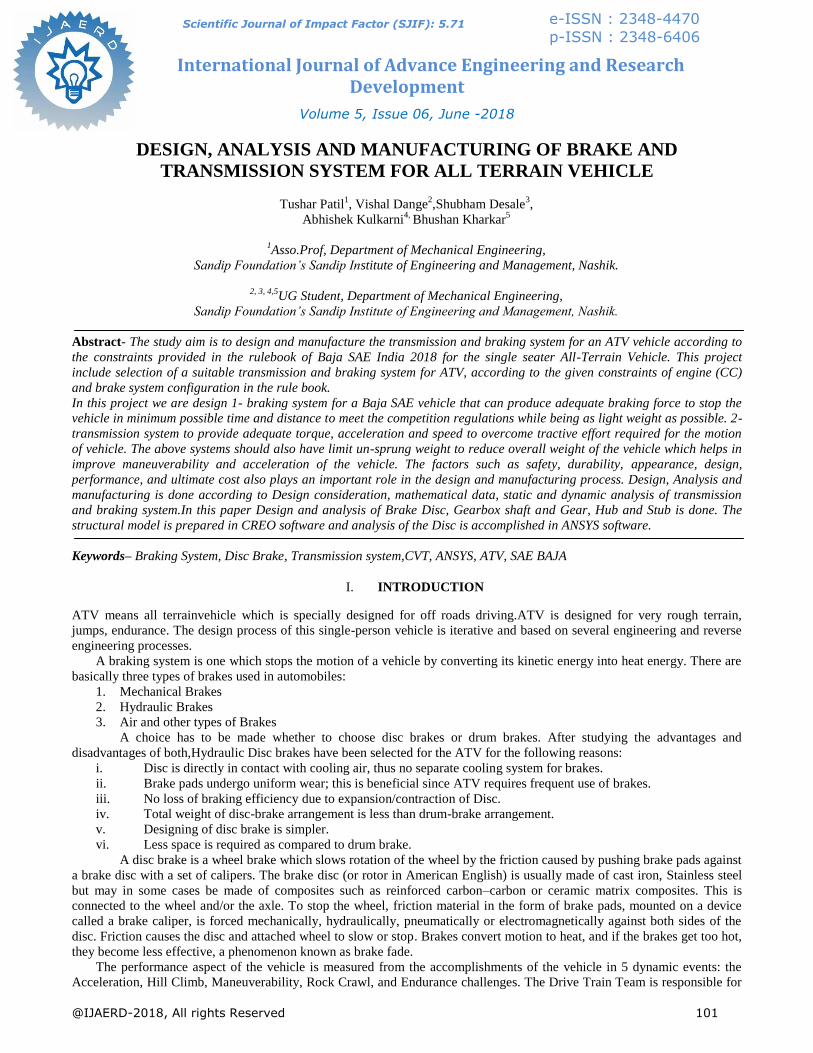
3.1 Brake Pedal
The main premise of a hydraulic braking system is very simple: driver force applied at the brake pedal is transferred
hydraulically to locations at the wheels or axle to reduce rotational speed and therefore vehicle speed. This simple task is
completed using the short list of components given in the previous section.
Beginning the process from the driver‟s effort to push one end of the brake pedal, the movement of the pedal actuates the
plunge rod that is attached to the other end of the pedal. This plunger rod moves a plunger inside the master cylinder and
decreases the volume within the cylinder, increasing the pressure of the fluid inside[2]
.
Figure1.BasicPedalDiagram
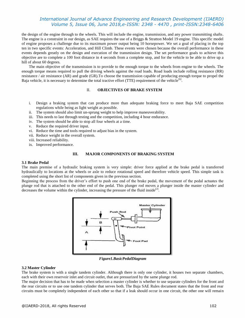
3.2 Master Cylinder The brake system is with a single tandem cylinder. Although there is only one cylinder, it houses two separate chambers,
each with their own reservoir inlet and circuit outlet, that are pressurized by the same plunge rod.
The major decision that has to be made when selection a master cylinder is whether to use separate cylinders for the front and
the rear circuits or to use one tandem cylinder that serves both. The Baja SAE Rules document states that the front and rear
circuits must be completely independent of each other so that if a leak should occur in one circuit, the other one will remain
International Journal of Advance Engineering and Research Development (IJAERD) Volume 5, Issue 06, June 2018,e-ISSN: 2348 - 4470 , print-ISSN:2348-6406
@IJAERD-2018, All rights Reserved 103
in working order. Both types of systems fulfil this requirement, but the pros and cons of each have to be considered before
making a selection. So we selected Tandem Master Cylinder of Maruti 800[4]
.
Figure2. Tandem Master Cylider of Maruti 800 (BOSCH)
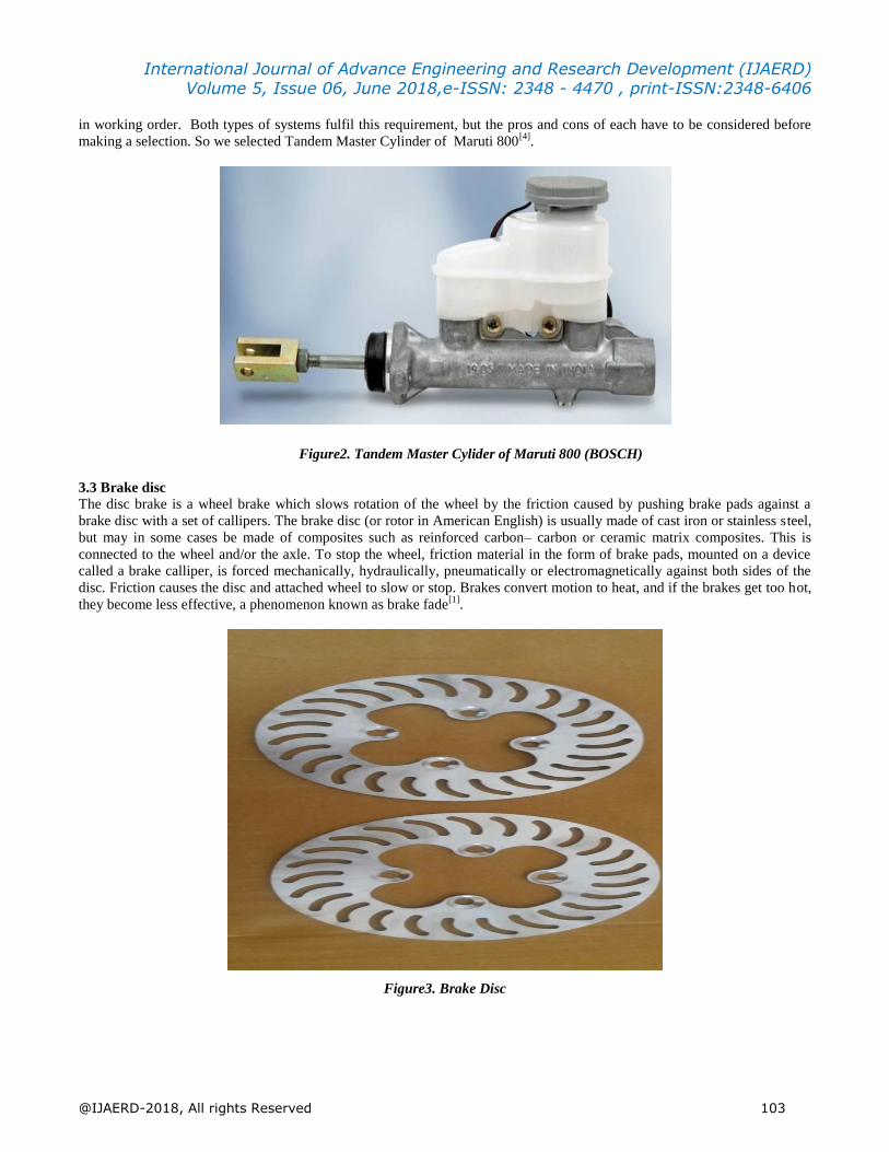
3.3 Brake disc
The disc brake is a wheel brake which slows rotation of the wheel by the friction caused by pushing brake pads against a
brake disc with a set of callipers. The brake disc (or rotor in American English) is usually made of cast iron or stainless steel,
but may in some cases be made of composites such as reinforced carbon– carbon or ceramic matrix composites. This is
connected to the wheel and/or the axle. To stop the wheel, friction material in the form of brake pads, mounted on a device
called a brake calliper, is forced mechanically, hydraulically, pneumatically or electromagnetically against both sides of the
disc. Friction causes the disc and attached wheel to slow or stop. Brakes convert motion to heat, and if the brakes get too hot,
they become less effective, a phenomenon known as brake fade[1]
.
Figure3. Brake Disc
International Journal of Advance Engineering and Research Development (IJAERD) Volume 5, Issue 06, June 2018,e-ISSN: 2348 - 4470 , print-ISSN:2348-6406
@IJAERD-2018, All rights Reserved 104
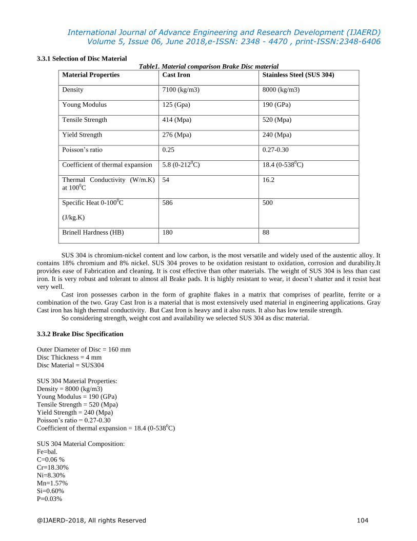
3.3.1 Selection of Disc Material
Table1. Material comparison Brake Disc material
Material Properties Cast Iron Stainless Steel (SUS 304)
Density 7100 (kg/m3) 8000 (kg/m3)
Young Modulus 125 (Gpa) 190 (GPa)
Tensile Strength 414 (Mpa) 520 (Mpa)
Yield Strength 276 (Mpa) 240 (Mpa)
Poisson‟s ratio 0.25 0.27-0.30
Coefficient of thermal expansion 5.8 (0-2120C) 18.4 (0-538
0C)
Thermal Conductivity (W/m.K)
at 1000C
54 16.2
Specific Heat 0-1000C
(J/kg.K)
586 500
Brinell Hardness (HB) 180 88
SUS 304 is chromium-nickel content and low carbon, is the most versatile and widely used of the austentic alloy. It
contains 18% chromium and 8% nickel. SUS 304 proves to be oxidation resistant to oxidation, corrosion and durability.It
provides ease of Fabrication and cleaning. It is cost effective than other materials. The weight of SUS 304 is less than cast
iron. It is very robust and tolerant to almost all Brake pads. It is highly resistant to wear, it doesn‟t shatter and it resist heat
very well.
Cast iron possesses carbon in the form of graphite flakes in a matrix that comprises of pearlite, ferrite or a
combination of the two. Gray Cast Iron is a material that is most extensively used material in engineering applications. Gray
Cast iron has high thermal conductivity. But Cast Iron is heavy and it also rusts. It also has low tensile strength.
So considering strength, weight cost and availability we selected SUS 304 as disc material.
3.3.2 Brake Disc Specification
Outer Diameter of Disc = 160 mm
Disc Thickness = 4 mm
Disc Material = SUS304
SUS 304 Material Properties:
Density = 8000 (kg/m3)
Young Modulus = 190 (GPa)
Tensile Strength = 520 (Mpa)
Yield Strength = 240 (Mpa)
Poisson‟s ratio = 0.27-0.30
Coefficient of thermal expansion = 18.4 (0-5380C)
SUS 304 Material Composition:
Fe=bal.
C=0.06 %
Cr=18.30%
Ni=8.30%
Mn=1.57%
Si=0.60%
P=0.03%
International Journal of Advance Engineering and Research Development (IJAERD) Volume 5, Issue 06, June 2018,e-ISSN: 2348 - 4470 , print-ISSN:2348-6406
@IJAERD-2018, All rights Reserved 105
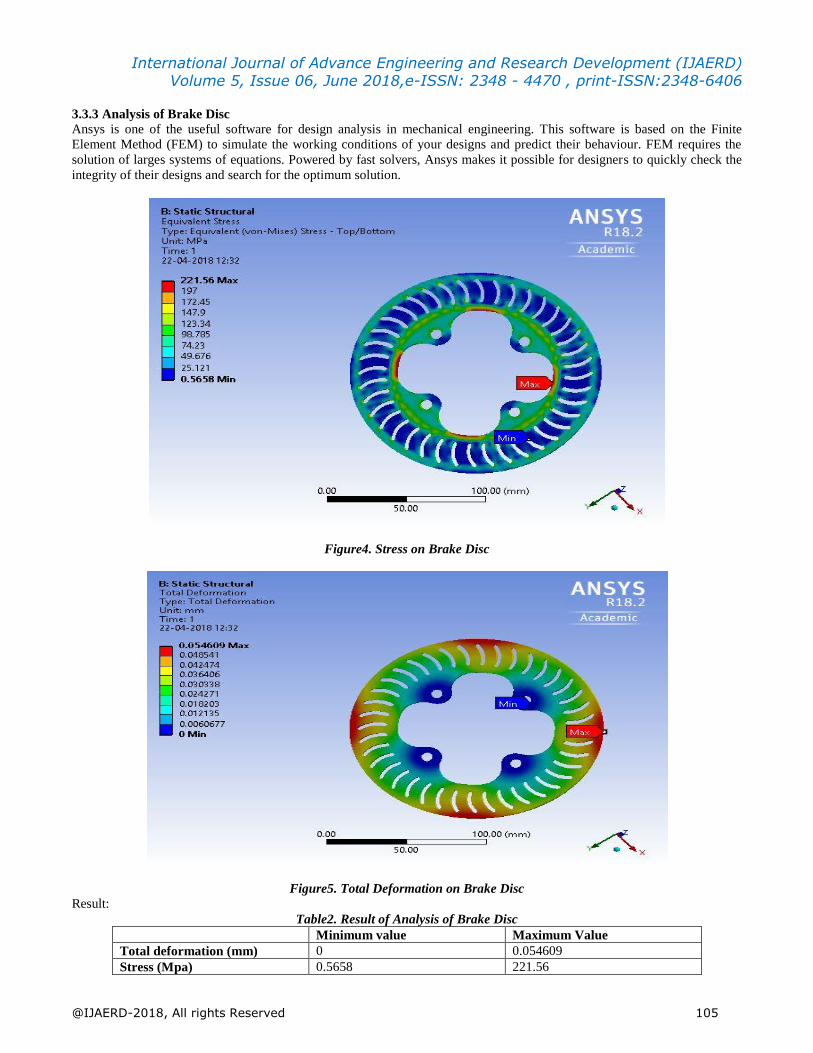
3.3.3 Analysis of Brake Disc
Ansys is one of the useful software for design analysis in mechanical engineering. This software is based on the Finite
Element Method (FEM) to simulate the working conditions of your designs and predict their behaviour. FEM requires the
solution of larges systems of equations. Powered by fast solvers, Ansys makes it possible for designers to quickly check the
integrity of their designs and search for the optimum solution.
Figure4. Stress on Brake Disc
Figure5. Total Deformation on Brake Disc Result:
Table2. Result of Analysis of Brake Disc
Minimum value Maximum Value
Total deformation (mm) 0 0.054609
Stress (Mpa) 0.5658 221.56

International Journal of Advance Engineering and Research Development (IJAERD) Volume 5, Issue 06, June 2018,e-ISSN: 2348 - 4470 , print-ISSN:2348-6406
@IJAERD-2018, All rights Reserved 106
3.4 Selection of Caliper
In a Disc-Braking system the car‟s wheels are attached to metal discs, or rotors, that spin along with the wheels. The job of
the caliper is to slow the car‟s wheels by creating friction with the rotors. It is a device which Holds pads and squeezes them
against rotor. The selection of the front and rear calipers were made primarily based on mounting ability. Following are our
design considerations
i. It should be compact in size so that appropriate mountings can be made.
ii. According to braking force required bore diameter is selected[7]
.
Figure6.Piaggio Vespa Caliper
3.5 Selection of Brake fluid
Selection of Brake Fluid is done by considering the characteristics of Brake fluid. We selected DOT 4 as a Brake Fluid.
The following are the reasons for selecting DOT 4 as a Brake Fluid.
i. Viscosity of DOT 4 Brake Fluid is more than any other Brake Fluid.
ii. DOT 4 Brake Fluid absorbs less water than DOT 3 Brake Fluid.
iii. It maintains its Fluidity at high temperature[8]
.
IV. SPECIFICATIONS FOR BRAKES
i. The pedal is with a pedal ratio of 6:1 for maximum leverage.
ii. Armoured steel braided brake lines run through the length of the car and flexible rubber lines at the A-arms in
the rear for suspension travel. These were chosen due to their flexibility and their strength and ability to
maintain high line pressure values.
iii. The reliability of our braking system is improved by having separate disk and calipers on each wheel. The
front and rear brakes consists of self-designed discs of 160mm OD, right and left caliper from piaggiovespa.
iv. The material of disc is SUS304.
v. Brake oil to be used is DOT 4.
V. CALCULATIONS FOR BRAKING SYSTEM
1) Deceleration =μ*g
For ATV μ is generally considered as 0.6
= 0.6*9.81
=5.886 m/s2
2) Total breaking force =mag
=180*0.6*9.81
International Journal of Advance Engineering and Research Development (IJAERD) Volume 5, Issue 06, June 2018,e-ISSN: 2348 - 4470 , print-ISSN:2348-6406
@IJAERD-2018, All rights Reserved 107
= 1059.48 N
3) Pedal Force Required = Total braking force /Pedal ratio
=1059.48/6
=176.58 N
4) Stopping Distance= V22μg
=12.52/2*0.6*9.81
=13.2730 m.
5) Stopping time= 2𝑠𝑈+𝑣
= 2∗13.2712.5+0 =2.12 sec.
6) Pedal Travel = 0.9∗𝑤∗𝑎𝑝𝑒𝑑𝑎𝑙𝑓𝑜𝑟𝑐𝑒
=0.9*180*9.81*0.6/176.58
=5.4 cm.
7) Weight Transfer= 𝑚∗𝑎∗𝐶𝐺𝑤ℎ𝑒𝑒𝑙𝑏𝑎𝑠𝑒
= 180∗0.588∗38.8660
=68.54 N
Weight Transfer=38%
VI. SELECTION OF TRANSMISSION SYSTEM
For baja buggy there is two options manual or automatic transmission system. After studying advantages and disadvantages
of both, Automatic transmission systems have been selected for an ATV for following reasons:
i. Less Driver fatigue.
ii. Better fuel efficiency.
iii. No loss of torque transmission from engine to the driving wheels during gearshifts.
iv. Faster acceleration and increased driving comfort.
v. It contributes to safer driving because the concentration of the driver is not disturbed by the need to change gear also
by both hands can remain on the steering wheel.
vi. Time consume due to gear shift is neglected in automatic transmission.
VII. MAJOR COMPONENTS OF TRANSMISSION SYSTEM
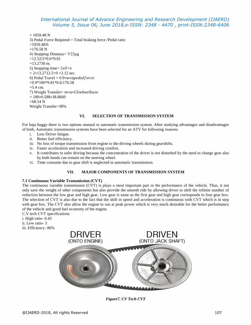
7.1 Continuous Variable Transmission (CVT)
The continuous variable transmission (CVT) is plays a most important part in the performance of the vehicle. Thus, it not
only save the weight of other components but also provide the smooth ride by allowing driver to shift the infinite number of
reduction between the low gear and high gear. Low gear is same as the first gear and high gear corresponds to four gear box.
The selection of CVT is also due to the fact that the shift in speed and acceleration is continuous with CVT which is in step
with gear box. The CVT also allow the engine to run at peak power which is very much desirable for the better performance
of the vehicle and good fuel economy of the engine.
C.V tech CVT specifications
i. High ratio- 0.43
ii. Low ratio- 3
iii. Efficiency- 86%
Figure7. CV Tech CVT
International Journal of Advance Engineering and Research Development (IJAERD) Volume 5, Issue 06, June 2018,e-ISSN: 2348 - 4470 , print-ISSN:2348-6406
@IJAERD-2018, All rights Reserved 108
7.2 Gearbox
Gearbox is a mechanical device which is used for transmitting motion or power from Engine to the road wheels by changing
the speed or torque or by changing the orientation of drive. We used 2 Stage Reduction Gearbox.
Functions of Gearbox: The Engine produces torque or tractive effort over a limited engine speed. But an automobile is driven
under different conditions requiring large variation in torque at road wheels. The main function of Gearbox is to provide a
mean to vary the torque ratio between the engine and the road wheels as and when required. It also required proper
arrangement for mounting of rollcage and for CV shaft[10]
.
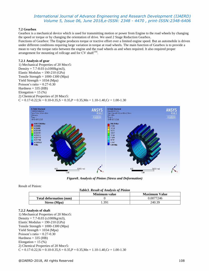
7.2.1 Analysis of gear
1) Mechanical Properties of 20 Mncr5:
Density = 7.7-8.03 (x1000kg/m3),
Elastic Modulus = 190-210 (GPa)
Tensile Strength = 1000-1300 (Mpa)
Yield Strength = 1034 (Mpa)
Poisson‟s ratio = 0.27-0.30
Hardness = 335 (HB)
Elongation = 15 (%)
2) Chemical Properties of 20 Mncr5:
C = 0.17-0.22,Si = 0.10-0.35,S = 0.35,P = 0.35,Mn = 1.10-1.40,Cr = 1.00-1.30
Figure8. Analysis of Pinion (Stress and Deformation)
Result of Pinion:
Table3. Result of Analysis of Pinion
Minimum value Maximum Value
Total deformation (mm) 0 0.0077246
Stress (Mpa) 1.391 240.39
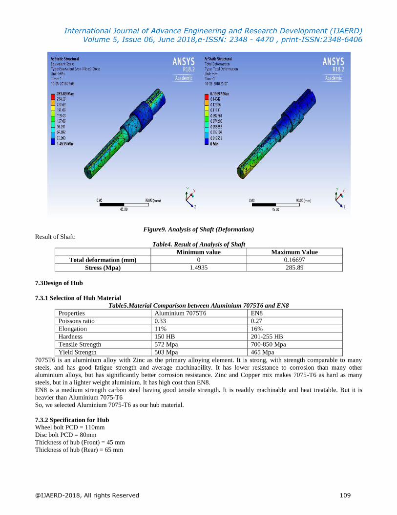
7.2.2 Analysis of shaft
1) Mechanical Properties of 20 Mncr5:
Density = 7.7-8.03 (x1000kg/m3),
Elastic Modulus = 190-210 (GPa)
Tensile Strength = 1000-1300 (Mpa)
Yield Strength = 1034 (Mpa)
Poisson‟s ratio = 0.27-0.30
Hardness = 335 (HB)
Elongation = 15 (%)
2) Chemical Properties of 20 Mncr5:
C = 0.17-0.22,Si = 0.10-0.35,S = 0.35,P = 0.35,Mn = 1.10-1.40,Cr = 1.00-1.30
International Journal of Advance Engineering and Research Development (IJAERD) Volume 5, Issue 06, June 2018,e-ISSN: 2348 - 4470 , print-ISSN:2348-6406
@IJAERD-2018, All rights Reserved 109
Figure9. Analysis of Shaft (Deformation)
Result of Shaft:
Table4. Result of Analysis of Shaft
Minimum value Maximum Value
Total deformation (mm) 0 0.16697
Stress (Mpa) 1.4935 285.89
7.3Design of Hub
7.3.1 Selection of Hub Material
Table5.Material Comparison between Aluminium 7075T6 and EN8
Properties Aluminium 7075T6 EN8
Poissons ratio 0.33 0.27
Elongation 11% 16%
Hardness 150 HB 201-255 HB
Tensile Strength 572 Mpa 700-850 Mpa
Yield Strength 503 Mpa 465 Mpa
7075T6 is an aluminium alloy with Zinc as the primary alloying element. It is strong, with strength comparable to many
steels, and has good fatigue strength and average machinability. It has lower resistance to corrosion than many other
aluminium alloys, but has significantly better corrosion resistance. Zinc and Copper mix makes 7075-T6 as hard as many
steels, but in a lighter weight aluminium. It has high cost than EN8.
EN8 is a medium strength carbon steel having good tensile strength. It is readily machinable and heat treatable. But it is
heavier than Aluminium 7075-T6
So, we selected Aluminium 7075-T6 as our hub material.
7.3.2 Specification for Hub
Wheel bolt PCD = 110mm
Disc bolt PCD = 80mm
Thickness of hub (Front) = 45 mm
Thickness of hub (Rear) = 65 mm
International Journal of Advance Engineering and Research Development (IJAERD) Volume 5, Issue 06, June 2018,e-ISSN: 2348 - 4470 , print-ISSN:2348-6406
@IJAERD-2018, All rights Reserved 110
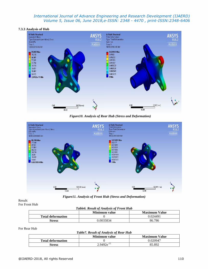
7.3.3 Analysis of Hub
Figure10. Analysis of Rear Hub (Stress and Deformation)
Figure11. Analysis of Front Hub (Stress and Deformation)
Result:
For Front Hub
Table6. Result of Analysis of Front Hub
Minimum value Maximum Value
Total deformation 0 0.024491
Stress 0.0035834 86.786
For Rear Hub
Table7. Result of Analysis of Rear Hub
Minimum value Maximum Value
Total deformation 0 0.020947
Stress 2.9492e-11
85.892
International Journal of Advance Engineering and Research Development (IJAERD) Volume 5, Issue 06, June 2018,e-ISSN: 2348 - 4470 , print-ISSN:2348-6406
@IJAERD-2018, All rights Reserved 111
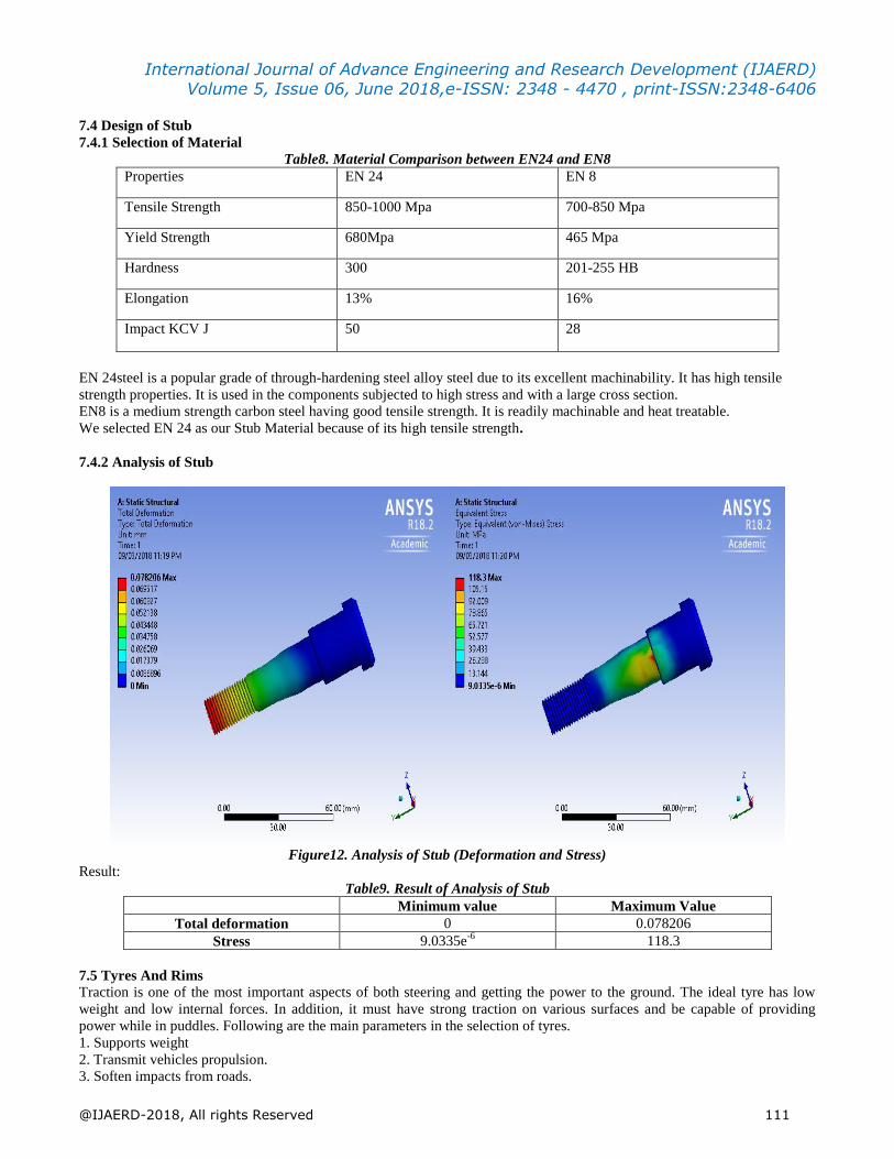
7.4 Design of Stub
7.4.1 Selection of Material
Table8. Material Comparison between EN24 and EN8
Properties EN 24 EN 8
Tensile Strength 850-1000 Mpa 700-850 Mpa
Yield Strength 680Mpa 465 Mpa
Hardness 300 201-255 HB
Elongation 13% 16%
Impact KCV J 50 28
EN 24steel is a popular grade of through-hardening steel alloy steel due to its excellent machinability. It has high tensile
strength properties. It is used in the components subjected to high stress and with a large cross section.
EN8 is a medium strength carbon steel having good tensile strength. It is readily machinable and heat treatable.
We selected EN 24 as our Stub Material because of its high tensile strength.
7.4.2 Analysis of Stub
Figure12. Analysis of Stub (Deformation and Stress)
Result:
Table9. Result of Analysis of Stub
Minimum value Maximum Value
Total deformation 0 0.078206
Stress 9.0335e-6
118.3
7.5 Tyres And Rims
Traction is one of the most important aspects of both steering and getting the power to the ground. The ideal tyre has low
weight and low internal forces. In addition, it must have strong traction on various surfaces and be capable of providing
power while in puddles. Following are the main parameters in the selection of tyres.
1. Supports weight
2. Transmit vehicles propulsion.
3. Soften impacts from roads.
International Journal of Advance Engineering and Research Development (IJAERD) Volume 5, Issue 06, June 2018,e-ISSN: 2348 - 4470 , print-ISSN:2348-6406
@IJAERD-2018, All rights Reserved 112
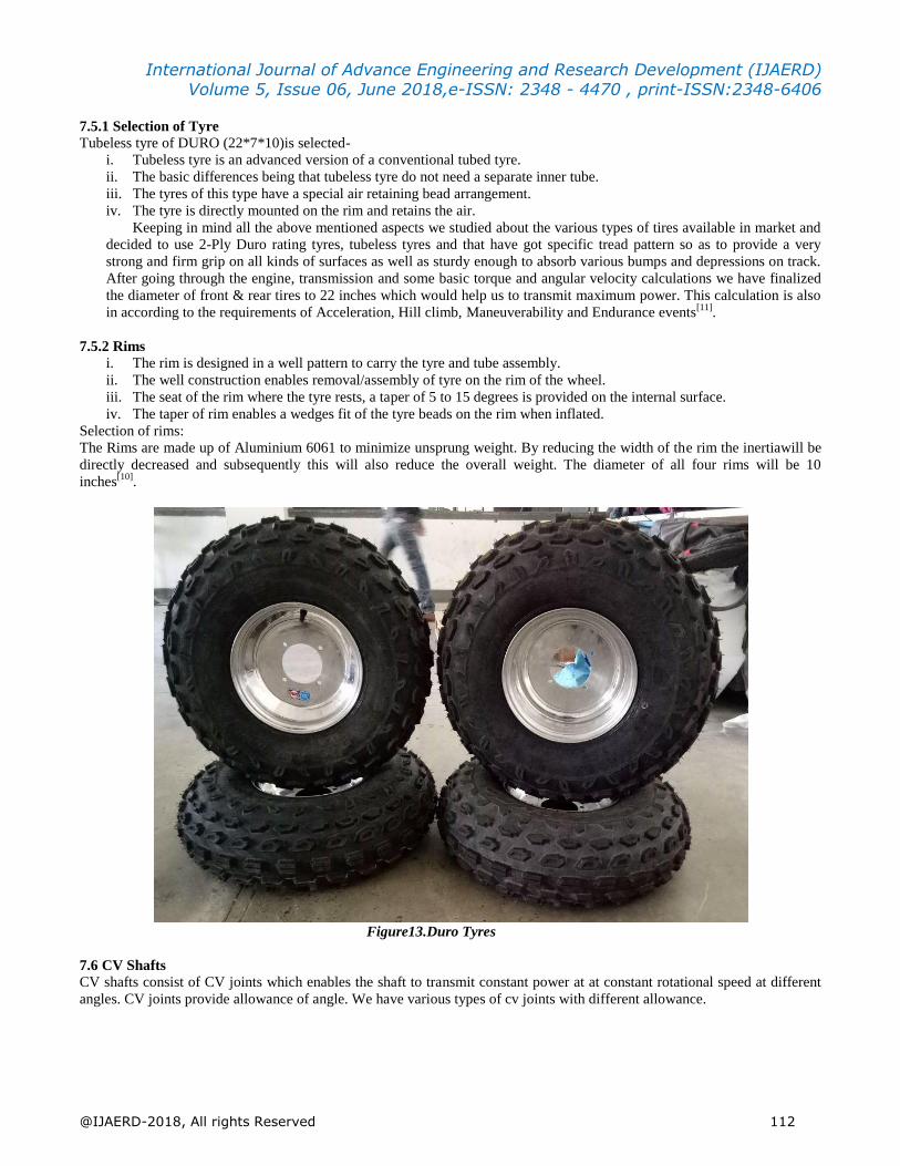
7.5.1 Selection of Tyre
Tubeless tyre of DURO (22*7*10)is selected-
i. Tubeless tyre is an advanced version of a conventional tubed tyre.
ii. The basic differences being that tubeless tyre do not need a separate inner tube.
iii. The tyres of this type have a special air retaining bead arrangement.
iv. The tyre is directly mounted on the rim and retains the air.
Keeping in mind all the above mentioned aspects we studied about the various types of tires available in market and
decided to use 2-Ply Duro rating tyres, tubeless tyres and that have got specific tread pattern so as to provide a very
strong and firm grip on all kinds of surfaces as well as sturdy enough to absorb various bumps and depressions on track.
After going through the engine, transmission and some basic torque and angular velocity calculations we have finalized
the diameter of front & rear tires to 22 inches which would help us to transmit maximum power. This calculation is also
in according to the requirements of Acceleration, Hill climb, Maneuverability and Endurance events[11]
.
7.5.2 Rims
i. The rim is designed in a well pattern to carry the tyre and tube assembly.
ii. The well construction enables removal/assembly of tyre on the rim of the wheel.
iii. The seat of the rim where the tyre rests, a taper of 5 to 15 degrees is provided on the internal surface.
iv. The taper of rim enables a wedges fit of the tyre beads on the rim when inflated.
Selection of rims:
The Rims are made up of Aluminium 6061 to minimize unsprung weight. By reducing the width of the rim the inertiawill be
directly decreased and subsequently this will also reduce the overall weight. The diameter of all four rims will be 10
inches[10]
.
Figure13.Duro Tyres
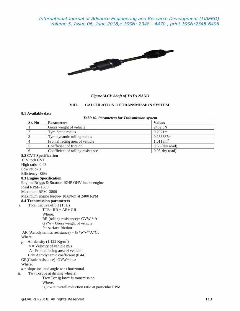
7.6 CV Shafts
CV shafts consist of CV joints which enables the shaft to transmit constant power at at constant rotational speed at different
angles. CV joints provide allowance of angle. We have various types of cv joints with different allowance.
International Journal of Advance Engineering and Research Development (IJAERD) Volume 5, Issue 06, June 2018,e-ISSN: 2348 - 4470 , print-ISSN:2348-6406
@IJAERD-2018, All rights Reserved 113
Figure14.CV Shaft of TATA NANO
VIII. CALCULATION OF TRANSMISSION SYSTEM
8.1 Available data
Table10. Parameters for Transmission system
Sr. No Parameters Values
1 Gross weight of vehicle 2452.5N
2 Tyre Static radius 0.2921m
3 Tyre dynamic rolling radius 0.283337m
4 Frontal facing area of vehicle 1.0119m2
5 Coefficient of friction 0.65 (dry road)
6 Coefficient of rolling resistance 0.05 dry road)
8.2 CVT Specification
C.V tech CVT
High ratio- 0.43
Low ratio- 3
Efficiency- 86%
8.3 Engine Specification
Engine: Briggs & Stratton 10HP OHV intake engine
Ideal RPM- 1800
Maximum RPM- 3800
Maximum engine torque- 18.6N-m at 2400 RPM
8.4 Transmission parameters
i. Total tractive effort (TTE)
TTE= RR + AR+ GR
Where,
RR (rolling resistance)= GVW * fr
GVW= Gross weight of vehicle
fr= surface friction
AR (Aerodynamics resistance) = ½ *𝜌*v2*A*Cd
Where,
𝜌 = Air density (1.122 Kg/m3)
v = Velocity of vehicle m/s
A= Frontal facing area of vehicle
Cd= Aerodynamic coefficient (0.44)
GR(Grade resistance)=GVW*sin𝛼
Where,
α = slope inclined angle w.r.t horizontal
ii. Tw (Torque at driving wheels)
Tw= Te* ig low* ƕ transmission
Where,
ig low = overall reduction ratio at particular RPM
International Journal of Advance Engineering and Research Development (IJAERD) Volume 5, Issue 06, June 2018,e-ISSN: 2348 - 4470 , print-ISSN:2348-6406
@IJAERD-2018, All rights Reserved 114
ƕ Transmission = ƕ gear pair * ƕ CVT* ƕ CV joints
=0.972* 0.86 * 0.98
2
= 0.793
= 79.3%
iii. Acceleration(a)
F = Ma therefore a = F/M
Where,
M = Total mass of vehicle in Kg
F = Surplus force available at driving wheels, N
F =(Fw – TTE)
Fw = Pull at driving wheels = Tw / Dynamic rolling radius of tyre
iv. CVT Ratios
Minimum ratio = 3 at 1900 RPM of engine
Maximum ratio = 0.43 at 3700 RPM of engine
CVT ratio at 2400 RPM of engine
By interpolation
X = 3+ (2400 – 1900)
(3700−1900) * (0.43-3)
= 2.2861
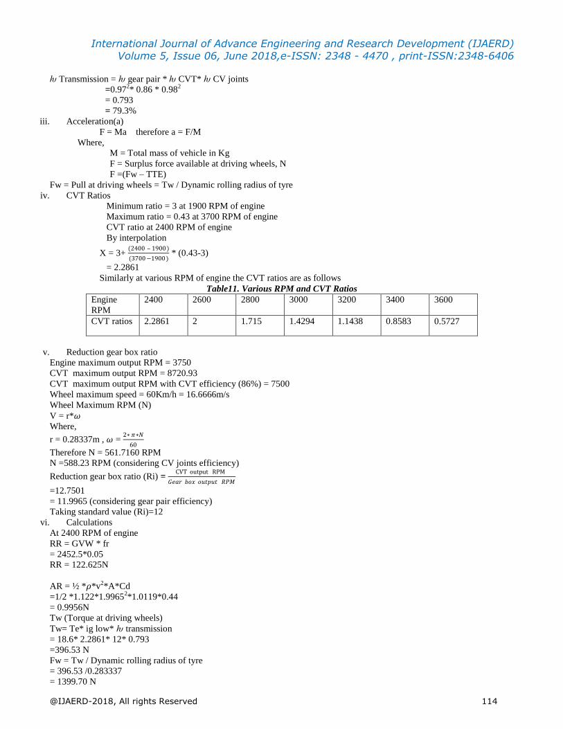
Similarly at various RPM of engine the CVT ratios are as follows
Table11. Various RPM and CVT Ratios
Engine
RPM
2400 2600 2800 3000 3200 3400 3600
CVT ratios 2.2861 2 1.715 1.4294 1.1438 0.8583 0.5727
v. Reduction gear box ratio
Engine maximum output RPM = 3750
CVT maximum output RPM = 8720.93
CVT maximum output RPM with CVT efficiency (86%) = 7500
Wheel maximum speed = 60Km/h = 16.6666m/s
Wheel Maximum RPM (N)
V = r*𝜔
Where,
r = 0.28337m , 𝜔 = 2∗ 𝜋∗𝑁
60
Therefore N = 561.7160 RPM
N =588.23 RPM (considering CV joints efficiency)
Reduction gear box ratio (Ri) = CVT output RPM
𝐺𝑒𝑎𝑟 𝑏𝑜𝑥 𝑜𝑢𝑡𝑝𝑢𝑡 𝑅𝑃𝑀
=12.7501
= 11.9965 (considering gear pair efficiency)
Taking standard value (Ri)=12
vi. Calculations
At 2400 RPM of engine
RR = GVW * fr
= 2452.5*0.05
RR = 122.625N
AR = ½ *𝜌*v2*A*Cd
=1/2 *1.122*1.99652*1.0119*0.44
= 0.9956N
Tw (Torque at driving wheels)
Tw= Te* ig low* ƕ transmission
= 18.6* 2.2861* 12* 0.793
=396.53 N
Fw = Tw / Dynamic rolling radius of tyre
= 396.53 /0.283337
= 1399.70 N
International Journal of Advance Engineering and Research Development (IJAERD) Volume 5, Issue 06, June 2018,e-ISSN: 2348 - 4470 , print-ISSN:2348-6406
@IJAERD-2018, All rights Reserved 115
F =(Fw – TTE) = (Fw – RR – AR – GR)
= 1399.70 –122.625 – 0.9956………(GR = 0 at flat road)
= 1276.08 N
Acceleration (a)
F = Ma therefore a = F/M
= 1276.08/250
= 5.10432 m/s2
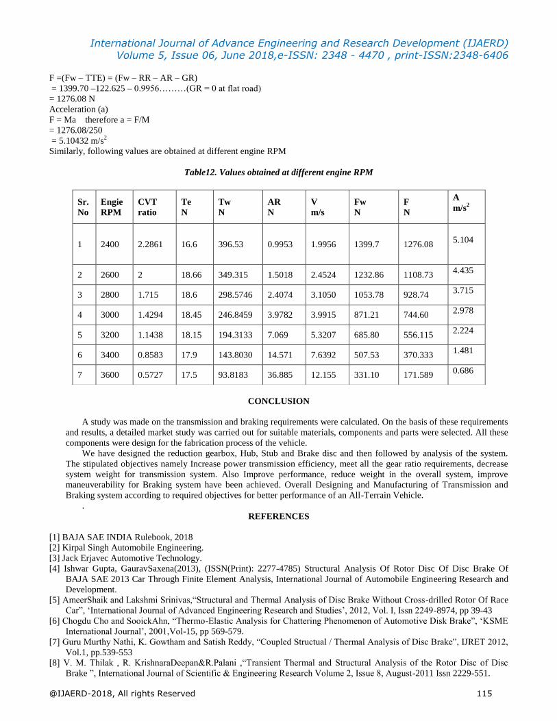
Similarly, following values are obtained at different engine RPM
Table12. Values obtained at different engine RPM
CONCLUSION
A study was made on the transmission and braking requirements were calculated. On the basis of these requirements
and results, a detailed market study was carried out for suitable materials, components and parts were selected. All these
components were design for the fabrication process of the vehicle.
We have designed the reduction gearbox, Hub, Stub and Brake disc and then followed by analysis of the system.
The stipulated objectives namely Increase power transmission efficiency, meet all the gear ratio requirements, decrease
system weight for transmission system. Also Improve performance, reduce weight in the overall system, improve
maneuverability for Braking system have been achieved. Overall Designing and Manufacturing of Transmission and
Braking system according to required objectives for better performance of an All-Terrain Vehicle.
.
REFERENCES
[1] BAJA SAE INDIA Rulebook, 2018
[2] Kirpal Singh Automobile Engineering.
[3] Jack Erjavec Automotive Technology.
[4] Ishwar Gupta, GauravSaxena(2013), (ISSN(Print): 2277-4785) Structural Analysis Of Rotor Disc Of Disc Brake Of
BAJA SAE 2013 Car Through Finite Element Analysis, International Journal of Automobile Engineering Research and
Development.
[5] AmeerShaik and Lakshmi Srinivas,“Structural and Thermal Analysis of Disc Brake Without Cross-drilled Rotor Of Race
Car”, „International Journal of Advanced Engineering Research and Studies‟, 2012, Vol. I, Issn 2249-8974, pp 39-43
[6] Chogdu Cho and SooickAhn, “Thermo-Elastic Analysis for Chattering Phenomenon of Automotive Disk Brake”, „KSME
International Journal‟, 2001,Vol-15, pp 569-579.
[7] Guru Murthy Nathi, K. Gowtham and Satish Reddy, “Coupled Structual / Thermal Analysis of Disc Brake”, IJRET 2012,
Vol.1, pp.539-553
[8] V. M. Thilak , R. KrishnaraDeepan&R.Palani ,“Transient Thermal and Structural Analysis of the Rotor Disc of Disc
Brake ”, International Journal of Scientific & Engineering Research Volume 2, Issue 8, August-2011 Issn 2229-551.
Sr.
No
Engie
RPM
CVT
ratio
Te
N
Tw
N
AR
N
V
m/s
Fw
N
F
N
A
m/s2
1 2400 2.2861 16.6 396.53 0.9953 1.9956 1399.7 1276.08
5.104
2 2600 2 18.66 349.315 1.5018 2.4524 1232.86 1108.73 4.435
3 2800 1.715 18.6 298.5746 2.4074 3.1050 1053.78 928.74 3.715
4 3000 1.4294 18.45 246.8459 3.9782 3.9915 871.21 744.60 2.978
5 3200 1.1438 18.15 194.3133 7.069 5.3207 685.80 556.115 2.224
6 3400 0.8583 17.9 143.8030 14.571 7.6392 507.53 370.333 1.481
7 3600 0.5727 17.5 93.8183 36.885 12.155 331.10 171.589 0.686
International Journal of Advance Engineering and Research Development (IJAERD) Volume 5, Issue 06, June 2018,e-ISSN: 2348 - 4470 , print-ISSN:2348-6406
@IJAERD-2018, All rights Reserved 116
[9] R.G. Mortimer, L. Segel, H. Dugoff, J.D. Campbell, C.M. Jorgeson, R.W. Murphy “Brake Force Requirement Study:
Driver- Vehicle Braking Performance as a Function of Brake System Design Variables”, Highway Safety Research
Institute, University of Michigan, April 10, 1970
[10] NenadMarjanovic , BiserkaIsailovic , VesnaMarjanovic , ZoranMilojevic , MirkoBlagojevic , MiloradBojic, A practical
approach to the optimization of gear trains with spur gears, Elsevier Ltd.doi:10.1016/j.mechmachtheory.2012.02.004
[11] Milosav Ognjanovic1 – Miroslav Milutinovic2, (2012), Design for Reliability Based Methodology For Automotive
Gearbox Load Capacity Identification”, Journal of Mechanical Engineering, Vol. 59 (5), pp. 311-322.
[12] AdityaPatankar, RohitKulkarni, SanketKothawade and Sameer Ingle, „Design And Development Of A Transmission
System For An All TerrainVehicle‟,International Journal of Mechanical Engineering and Technology (IJMET) Volume
7, Issue 3, May–June 2016
[13] P. P. C. D. S. B. Jaju, "A Review on Thermal and contact stress analysis of Disc braking system,"International Journal of
Engineering Research and General Science, vol. 2, no. 1, pp. 78-84, 2014
[14] D. Swapnil R. Abhang, "Design and Analysis of Disc Brake," International Journal of Engineering Trend
andTechnology, vol. 8, pp. 165-, 2014.