investigation on applicability of substitute...
TRANSCRIPT
International Journal of Advance Engineering and Research Development
Volume 5, Issue 03, March -2018
@IJAERD-2018, All rights Reserved 701
Scientific Journal of Impact Factor (SJIF): 5.71 e-ISSN (O): 2348-4470 p-ISSN (P): 2348-6406
INVESTIGATION ON APPLICABILITY OF SUBSTITUTE BEAM-COLUMN
FRAME FOR DESIGN OF REINFORCED CONCRETE SWAY FRAMES
1Deressa Ajema, 2Vorsha Yadav
1 Department of civil engineering, Parul Institute of Engineering & Technology
Faculty of Engineering & Technology Parul University 2Department of civil engineering, Parul Institute of Engineering & Technology
Faculty of Engineering & Technology Parul University
ABSTRACT- Although Ethiopian Building Code Standard, EBCS-2, is based on the Eurocode, EC-2, there are some
clear differences between the two codes, most notably, with respect to the provisions for the design of slender columns in
sway frames. The provision in the EBCS -2 for columns in sway frames is based on the American concrete institute, ACI;
however, the former introduces the concept of the substitute frame, which is not in the ACI, to determine the stiffness of
columns for the determination of the critical load, Ncr, thereby the sway moment magnification factor. This research is
thus intended to investigate the suitability of the substitute frame for the intended purpose by comparing the design
internal actions obtained based on the ACI and EBCS sway moment magnification provisions with the iterative P-Δ
second order analysis, which is believed to be a more realistic approach, by taking different types of building frames
subjected to different loading conditions. The results of the investigation reveal that, though the results are on the unsafe
side, the provision in EBCS-2 yields design moments close to the iterative P-Δ second order analysis, except for the case
of frames with vertical irregularities where it deviates by 6.4%.
Keywords-Sway frames, slender columns, substitute beam-column frame, ETABS, critical load, sway moment
magnification, second-order analysis.
I. INTRODUCTION
Columns are vertical structural members supporting axial compressive loads, with or without moments. They mainly
support vertical loads transferred from floors and roof and transfer the loads to the foundations. Although columns are
mainly meant for their axial compression capacity, they, in many cases, are subjected to bending moments about one or
both axes of the cross section due to eccentric loading or transverse loading.
Because of the occurrence of these moments, the axial load capacity of columns, which they are intended for, decreases
substantially. Interaction diagrams are usually used to describe the interaction between moment and axial load in a
column, and determine the failure loads.
The maximum moment in a column could happen at the ends as in columns of sway frames or somewhere at the span of
the column in between the two ends as in slender columns of nonsway frames. The analysis and design of columns in
sway and nonsway frames have distinct procedures given in codes. However, the analysis and design procedures given in
the Ethiopian Building Code Standard, EBCS-2[4] for the design of slender columns in sway frames need detail
investigations.
II. BACKGROUND OF THE STUDY
It is well known that the Ethiopian Building Code Standard, EBCS-2- Part 1[4] is based on the previous versions of Euro
code, EC-2[5]. As a result, the two Codes are very similar, with only few exceptions in some parts of the Codes. One of
the sections where EBCS-2[4] deviates significantly from EC-2[5] is with respect to the provisions for the design of
columns in sway frames.
EC-2[5] gives detailed simplified design provisions for slender reinforced concrete columns that may be considered as
isolated columns. These are individual columns with articulation in non-sway structures, slender bracing elements, and
columns with restrained ends in a non-sway structure. Corresponding provisions for the design of columns in sway
frames are not provided by EC-2[5]. According to EC-2[5], such columns are to be designed using the more rigorous
approach based on the results of a second order global analysis.
International Journal of Advance Engineering and Research Development (IJAERD)
Volume 5, Issue 03, March-2018, e-ISSN: 2348 - 4470, print-ISSN: 2348-6406
@IJAERD-2018, All rights Reserved 702
The EBCS-2[4] seems to be more complete in this respect, because it gives additional simplified procedures for the
design of columns in sway frames. A closer look into the provisions reveals that they are based on the corresponding
procedures according to the American Concrete Institute, ACI [1]. The interrelationships between the two provisions,
however, are not immediately obvious because of some significant differences in the procedures such as the concept of
the substitute frame adopted by EBCS-2[4] for column stiffness computation.
Therefore the design of slender reinforced concrete columns in sway frames has long been a controversial subject among
practicing structural engineers with lack of consensus with regard to its suitability as a design tool or even the validity of
the results. [10]
Zerayohannes G. [10] has tried to address this issue through his paper “Influence of ACI Provisions for the Design of
Columns in Sway Frames on EBCS-2:1995”; however, only one frame has been used to compare the results with the
results of the ACI provision. It is thus very important to make a detailed investigation on the validity of the results
obtained from the provision in EBCS-2[4] by comparing them with the provision in ACI [1] and iterative P-Δ second
order analysis results, by taking different sway frame models of varying story number and height for different load
conditions.
III. DESIGN PROVISIONS FOR SLENDER COLUMNS IN SWAY FRAMES
ACCORDING TO ACI AND EBCS CODES
3.1. Introduction
Column moments due to symmetric gravity loads do not cause appreciable sway. They are magnified when the column
deflects by an amount ẟ relative to its original straight axis such that the moments at points along the length of the
column exceed those at the ends. This is referred to as the member stability effect or P-δ effect, where the lower case
refers to deflections relative to the chord joining the ends of the column. Such column end moments should not be
magnified by P- ẟ moments.
Column moments due to lateral loads, on the other hand, cause appreciable sway. They are magnified by the P-
moments resulting from sway deflections, ẟ of the beam-column joints in the frame from their original undeflected
locations. This is referred to as the P-Δ effect or lateral drift effect.
Treating the P-δ and P-Δ moments separately simplifies design. The nonsway moments frequently result from a series of
pattern loads. The pattern loads can lead to a moment envelope for the nonsway moments. The maximum end moments
from the moment envelope are then combined with the magnified sway moments from a second-order analysis or from a
sway moment-magnifier analysis.
The two codes, ACI and EBCS, seem to have similar provisions for design of slender columns in sway frames but they
do have some clear differences in some aspects. One of these major differences is the introduction of the substitute beam-
column frame in the EBCS for the determination of the effective column stiffness in sway frames to calculate the critical
buckling loads.
A detail and closer view of the provisions of the two codes for the design of slender columns is thus necessary to
investigate the acceptability of the results obtained from the substitute beam-column frame given in EBCS-2.
3.2. Moment Magnification Procedure for Sway Frames According to ACI
3.2.1. Factored Load Combinations
Three different load cases shall be considered.
Case 1: Gravity and wind loads, U = 0.75(1.4D + 1.7L) + (1.6W), (3.1)
For wind loads that did not include a directionality factor, 1.6W drops to 1.3W.
Assuming it did not: U = 1.05D + 1.275L 1.3W. (3.2)
Case 2: Gravity and EQ loads, U = 0.75(1.4D + 1.7L) + (1.0E), (3.3)
U = 1.05D + 1.275L + 1.0E, (3.4)
Case 3: Gravity loads only, U = 1.4D + 1.7L (3.5)
3.2.2. Check whether a Story is Sway or Not
According to ACI 318-08 Section 10.10.5.2, a story in a frame can be assumed nonsway if.
Q= ≤0.05 (3.6)
Where, Q = stability index
International Journal of Advance Engineering and Research Development (IJAERD)
Volume 5, Issue 03, March-2018, e-ISSN: 2348 - 4470, print-ISSN: 2348-6406
@IJAERD-2018, All rights Reserved 703
= total factored axial load in the story
Δ o = 1st order relative deflection between the top and bottom of that story due to Vu
lc = story height
NB: Pu, Δo and Vu shall be obtained from elastic first-order analysis using section properties prescribed in
ACI 318-08, section 10.10.4.1.
3.2.3. Check the Stability of the Structure as a Whole under Gravity Loads Only
In addition to load combinations involving lateral loads, the strength and stability of the structure as a whole under
gravity loads shall be considered. ACI 318-05, Section 10.13.6 states that side-sway buckling will not be a problem if the
following conditions are satisfied.
a) When δ sMs is computed from second-order elastic analysis, i.e. method (i) of section 3.2.5, the ratio of second-
order lateral deflections to first-order lateral deflections for factored dead and live loads plus factored lateral
loads applied to the structure shall not exceed 2.5;
b) When δ sMs is computed from equation (3.12), the value of Q computed using for factored dead and live
loads shall not exceed 0.60 which is equivalent to δs = 2.5;
c) When δ sMs is computed from equation (3.13), δs computed using for 1.4D + 1.7L and based on
0.40 EI/ (1 + βd), shall be positive and shall not exceed 2.5.
In a), b) and c) above, βd shall be taken as the ratio of the total sustained axial loads to the total axial loads, as
defined in ACI 318-05, Section 10.13.6.
d) According to ACI318-08, however, the check is made simply by limiting the ratio of the total moment including
second order effects to first-order moments to 1.40.
3.3. Moment Magnification Procedure for Sway Frames According to EBCS
3.3.1. Factored Load Combinations
Three different load cases shall be considered.
Case 1: Gravity and wind loads, Sd = S (1.20(G + Qvk + Qhk) (3.7)
Sd = 1.20D + 1.20L ± 1.20W (3.8)
Case 2: Gravity and earthquake loads, Sd =0.75(1.30D + 1.60L) ± 1.0E (3.9)
Sd =0.975D + 1.20L ± 1.0E (3.10)
Case 3: Gravity loads only, Sd = S (1.30G + 1.60Qvk) (3.11)
3.3.2. Check whether a Story is Sway or Not
According to Section 4.4.4.2 of EBCS-2, 1995, a story in a given frame may be classified as non-sway story if:
≤0.1
Beam-and-column type plane frames in building structures with beams connecting each column at each story level may
be classified as non-sway story if:
≤0.1
Where, in both equations,
NSd, N = total factored axial load in the story,
Ncr = story buckling load,
H = total horizontal reaction (shear) at the bottom of the story,
δ = first-order relative deflection between the top and bottom of that story due to the design loads (vertical
and horizontal), plus the initial sway imperfection,
L = story height.
The displacement δ shall be determined based on stiffness values for beams and columns appropriate to Ultimate Limit
State.
International Journal of Advance Engineering and Research Development (IJAERD)
Volume 5, Issue 03, March-2018, e-ISSN: 2348 - 4470, print-ISSN: 2348-6406
@IJAERD-2018, All rights Reserved 704
3.3.3. Check the Stability of the Structure as a Whole under Gravity Loads Only
EBCS-2 section 4.4.8.1(1) states that all frames shall have adequate resistance to failure in a sway mode,
but it does not place any explicit limit on s or the critical load ratio as in the ACI
IV. RESULTS AND DISCUSSIONS
Four different types of frames have been analyzed according to the ACI and EBCS sway moment magnification
provisions for the intended purpose. The results obtained from the two provisions have been compared with iterative P-Δ
analysis results for the corresponding load combinations. The analysis outputs of each frame have been summarized and
discussed in the preceding sections. One can refer the appendices for detail analyses of the frames.
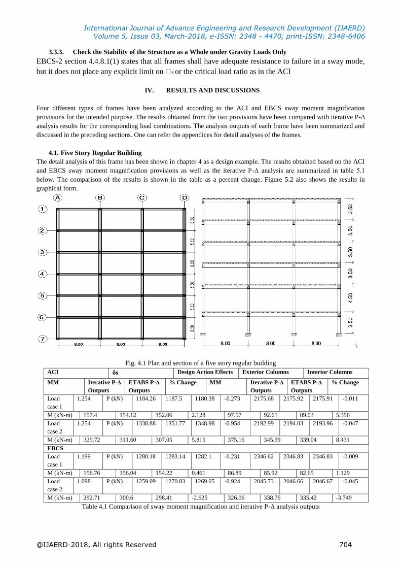
4.1. Five Story Regular Building
The detail analysis of this frame has been shown in chapter 4 as a design example. The results obtained based on the ACI
and EBCS sway moment magnification provisions as well as the iterative P-Δ analysis are summarized in table 5.1
below. The comparison of the results is shown in the table as a percent change. Figure 5.2 also shows the results in
graphical form.
\
Fig. 4.1 Plan and section of a five story regular building
ACI δs Design Action Effects Exterior Columns Interior Columns
MM Iterative P-Δ
Outputs
ETABS P-Δ
Outputs
% Change MM Iterative P-Δ
Outputs
ETABS P-Δ
Outputs
% Change
Load
case 1
1.254 P (kN) 1184.26 1187.5 1180.38 -0.273 2175.68 2175.92 2175.91 -0.011
M (kN-m) 157.4 154.12 152.06 2.128 97.57 92.61 89.03 5.356
Load
case 2
1.254 P (kN) 1338.88 1351.77 1348.98 -0.954 2192.99 2194.03 2193.96 -0.047
M (kN-m) 329.72 311.60 307.05 5.815 375.16 345.99 339.04 8.431
EBCS
Load
case 1
1.199 P (kN) 1280.18 1283.14 1282.1 -0.231 2346.62 2346.83 2346.83 -0.009
M (kN-m) 156.76 156.04 154.22 0.461 86.89 85.92 82.65 1.129
Load
case 2
1.098 P (kN) 1259.09 1270.83 1269.05 -0.924 2045.73 2046.66 2046.67 -0.045
M (kN-m) 292.71 300.6 298.41 -2.625 326.06 338.76 335.42 -3.749
Table 4.1 Comparison of sway moment magnification and iterative P-Δ analysis outputs
International Journal of Advance Engineering and Research Development (IJAERD)
Volume 5, Issue 03, March-2018, e-ISSN: 2348 - 4470, print-ISSN: 2348-6406
@IJAERD-2018, All rights Reserved 705
Where: δs = Sway moment magnification factor
MM = Results of the Sway moment magnifier method provisions,
Iterative P-Δ = Results of iterative P-Δ analysis method (calculated manually)
Etabs P-Δ = Results of Etabs 9.7.4 software iterative P-Δ analysis
Load case 1 = gravity and wind loads
=
Load case 2 = gravity and earthquake loads
=
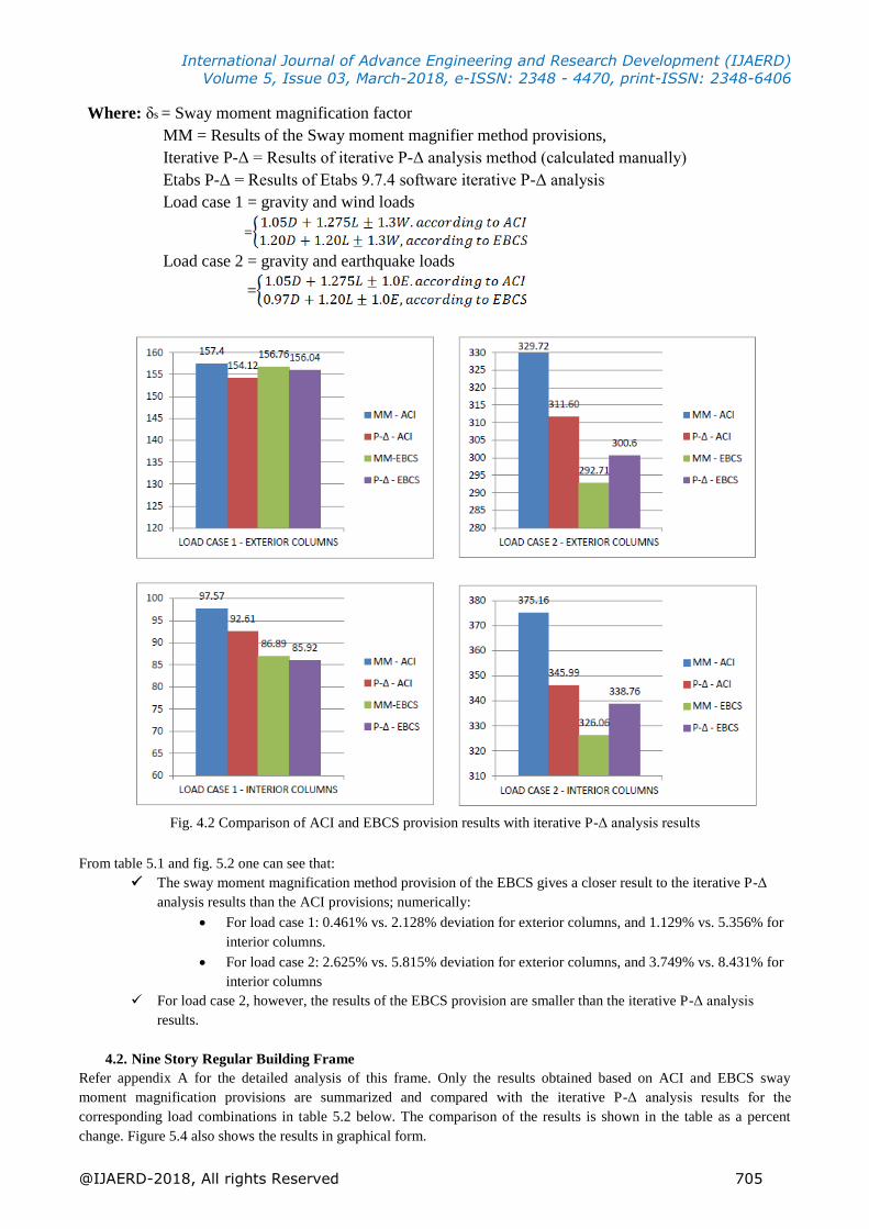
Fig. 4.2 Comparison of ACI and EBCS provision results with iterative P-Δ analysis results
From table 5.1 and fig. 5.2 one can see that:
The sway moment magnification method provision of the EBCS gives a closer result to the iterative P-Δ
analysis results than the ACI provisions; numerically:
For load case 1: 0.461% vs. 2.128% deviation for exterior columns, and 1.129% vs. 5.356% for
interior columns.
For load case 2: 2.625% vs. 5.815% deviation for exterior columns, and 3.749% vs. 8.431% for
interior columns
For load case 2, however, the results of the EBCS provision are smaller than the iterative P-Δ analysis
results.
4.2. Nine Story Regular Building Frame
Refer appendix A for the detailed analysis of this frame. Only the results obtained based on ACI and EBCS sway
moment magnification provisions are summarized and compared with the iterative P-Δ analysis results for the
corresponding load combinations in table 5.2 below. The comparison of the results is shown in the table as a percent
change. Figure 5.4 also shows the results in graphical form.
International Journal of Advance Engineering and Research Development (IJAERD)
Volume 5, Issue 03, March-2018, e-ISSN: 2348 - 4470, print-ISSN: 2348-6406
@IJAERD-2018, All rights Reserved 706
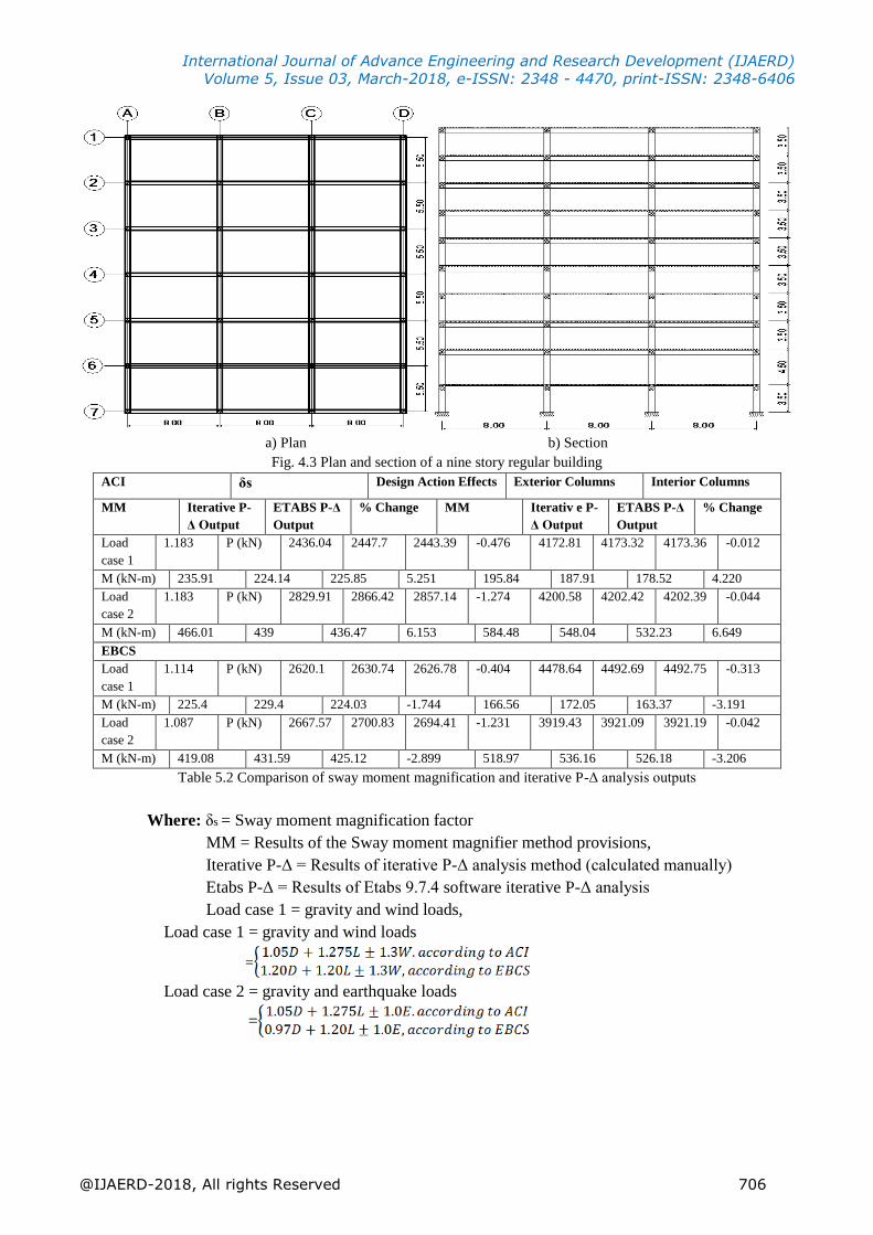
a) Plan b) Section
Fig. 4.3 Plan and section of a nine story regular building
ACI δs Design Action Effects Exterior Columns Interior Columns
MM Iterative P-
Δ Output
ETABS P-Δ
Output
% Change MM Iterativ e P-
Δ Output
ETABS P-Δ
Output
% Change
Load
case 1
1.183 P (kN) 2436.04 2447.7 2443.39 -0.476 4172.81 4173.32 4173.36 -0.012
M (kN-m) 235.91 224.14 225.85 5.251 195.84 187.91 178.52 4.220
Load
case 2
1.183 P (kN) 2829.91 2866.42 2857.14 -1.274 4200.58 4202.42 4202.39 -0.044
M (kN-m) 466.01 439 436.47 6.153 584.48 548.04 532.23 6.649
EBCS
Load
case 1
1.114 P (kN) 2620.1 2630.74 2626.78 -0.404 4478.64 4492.69 4492.75 -0.313
M (kN-m) 225.4 229.4 224.03 -1.744 166.56 172.05 163.37 -3.191
Load
case 2
1.087 P (kN) 2667.57 2700.83 2694.41 -1.231 3919.43 3921.09 3921.19 -0.042
M (kN-m) 419.08 431.59 425.12 -2.899 518.97 536.16 526.18 -3.206
Table 5.2 Comparison of sway moment magnification and iterative P-Δ analysis outputs
Where: δs = Sway moment magnification factor
MM = Results of the Sway moment magnifier method provisions,
Iterative P-Δ = Results of iterative P-Δ analysis method (calculated manually)
Etabs P-Δ = Results of Etabs 9.7.4 software iterative P-Δ analysis
Load case 1 = gravity and wind loads,
Load case 1 = gravity and wind loads
=
Load case 2 = gravity and earthquake loads
=
International Journal of Advance Engineering and Research Development (IJAERD)
Volume 5, Issue 03, March-2018, e-ISSN: 2348 - 4470, print-ISSN: 2348-6406
@IJAERD-2018, All rights Reserved 707
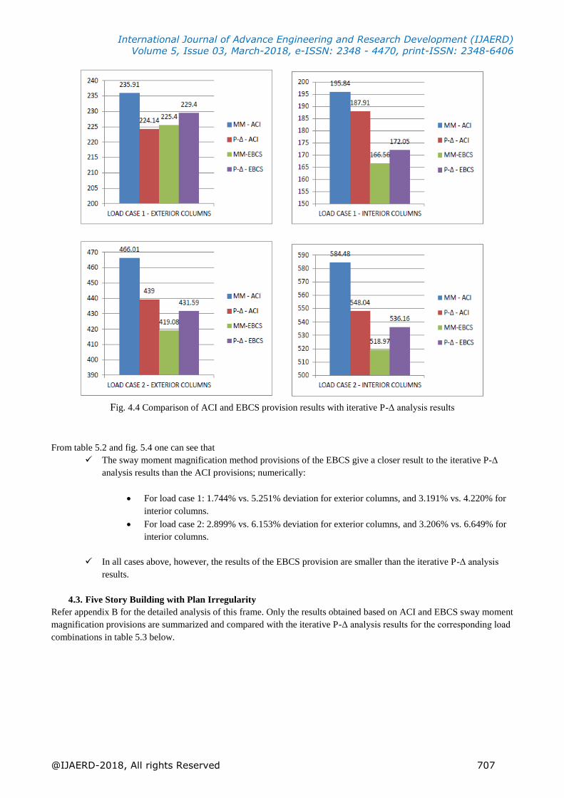
Fig. 4.4 Comparison of ACI and EBCS provision results with iterative P-Δ analysis results
From table 5.2 and fig. 5.4 one can see that
The sway moment magnification method provisions of the EBCS give a closer result to the iterative P-Δ
analysis results than the ACI provisions; numerically:
For load case 1: 1.744% vs. 5.251% deviation for exterior columns, and 3.191% vs. 4.220% for
interior columns.
For load case 2: 2.899% vs. 6.153% deviation for exterior columns, and 3.206% vs. 6.649% for
interior columns.
In all cases above, however, the results of the EBCS provision are smaller than the iterative P-Δ analysis
results.
4.3. Five Story Building with Plan Irregularity
Refer appendix B for the detailed analysis of this frame. Only the results obtained based on ACI and EBCS sway moment
magnification provisions are summarized and compared with the iterative P-Δ analysis results for the corresponding load
combinations in table 5.3 below.
International Journal of Advance Engineering and Research Development (IJAERD)
Volume 5, Issue 03, March-2018, e-ISSN: 2348 - 4470, print-ISSN: 2348-6406
@IJAERD-2018, All rights Reserved 708
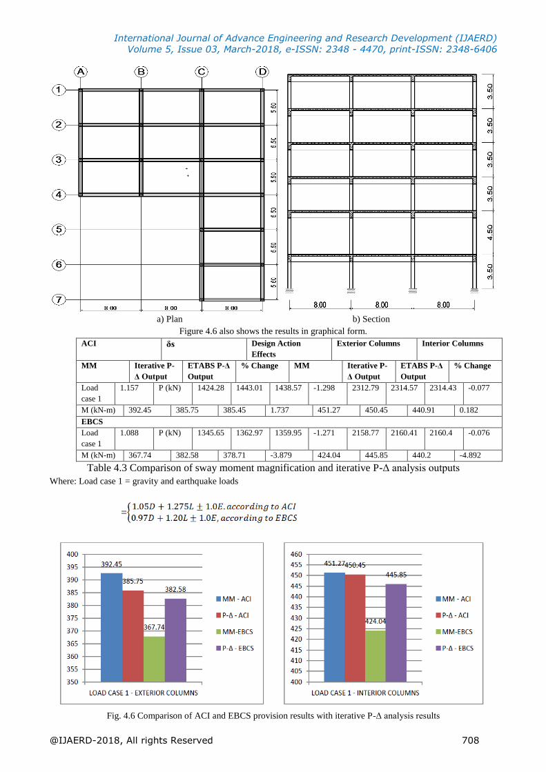
a) Plan b) Section
Figure 4.6 also shows the results in graphical form.
ACI δs Design Action
Effects
Exterior Columns Interior Columns
MM Iterative P-
Δ Output
ETABS P-Δ
Output
% Change MM Iterative P-
Δ Output
ETABS P-Δ
Output
% Change
Load
case 1
1.157 P (kN) 1424.28 1443.01 1438.57 -1.298 2312.79 2314.57 2314.43 -0.077
M (kN-m) 392.45 385.75 385.45 1.737 451.27 450.45 440.91 0.182
EBCS
Load
case 1
1.088 P (kN) 1345.65 1362.97 1359.95 -1.271 2158.77 2160.41 2160.4 -0.076
M (kN-m) 367.74 382.58 378.71 -3.879 424.04 445.85 440.2 -4.892
Table 4.3 Comparison of sway moment magnification and iterative P-Δ analysis outputs
Where: Load case 1 = gravity and earthquake loads
=
Fig. 4.6 Comparison of ACI and EBCS provision results with iterative P-Δ analysis results
International Journal of Advance Engineering and Research Development (IJAERD)
Volume 5, Issue 03, March-2018, e-ISSN: 2348 - 4470, print-ISSN: 2348-6406
@IJAERD-2018, All rights Reserved 709
From table 4.3 and fig. 4.6 one can see that:
The sway moment magnification provision of the ACI gives a closer result to the iterative P-Δ analysis
results than the EBCS provisions. Numerically, 1.737% vs. 3.879% deviation for exterior columns, and
0.182% vs. 4.892% for interior columns.
The results of the EBCS provision are smaller than the iterative P-Δ analysis results.
V. CONCLUSIONS AND RECOMMENDATIONS
5.1. Conclusions
From this research the following conclusions have been made
1. Generally, the ACI provisions give more conservative results (higher design axial load and design moment) than
those of the EBCS provisions reflecting the differences in load combinations used in the two codes. However,
when designing structures for gravity and wind loads, the axial loads obtained from EBCS provisions are higher
than those from ACI provisions.
2. In all the building frames considered, except the case with plannar irregularity, the EBCS provision gives results
closer to the iterative P-Δ analysis than the ACI provision, although the results are, almost always, on the unsafe
side.
3. Unlike the ACI provision, the sway moment magnification provision of the EBCS gives design moments
smaller than the iterative P-Δ analysis outputs, with maximum deviation of 6.365% for the nine story frame with
vertical irregularity.
4. Results of the design examples also show that the sway-moment magnification factors from EBCS provision are
slightly less than the ACI sway moment magnification factors in all cases.
5. While using the sway moment magnification provision of the EBCS for designing slender columns in sway
frames, one has to recall that the sway-moment magnification factor is different for different load conditions.
This is because of the introduction of the substitute frame which has to be designed for the load combination
under consideration to determine the effective stiffness, critical load and hence the sway moment magnification
factor.
6. The provision in EBCS does not give any explicit limit as in the ACI for checking frame stability under gravity
loads only; though it requires the check to be made.
5.2. Recommendations
1. When using the EBCS provision for the design of slender columns of reinforced concrete sway frames, the
author recommends increasing the design moments by 3 -7%, higher values for buildings with irregularities (up
to nine stories), which does not significantly affect the overall economy of the structure while ensuring safety.
However, further study is needed to give exact correction factors for different frames.
2. When using the sway moment magnification method provisions of the ACI and the EBCS for the design of
slender columns of sway frames with irregularities, precaution should be made since the reliability of the results
decreases with irregularities.
3. The author recommends the following limits for checking the possibility of sidesway buckling under gravity
loads only, which are equivalent to the limits in ACI 318-05.
i. When sMs is computed from second-order elastic analysis, the ratio of second-order lateral
deflections to first-order lateral deflections for factored dead and live loads plus factored
lateral loads applied to the structure shall not exceed 2.5;
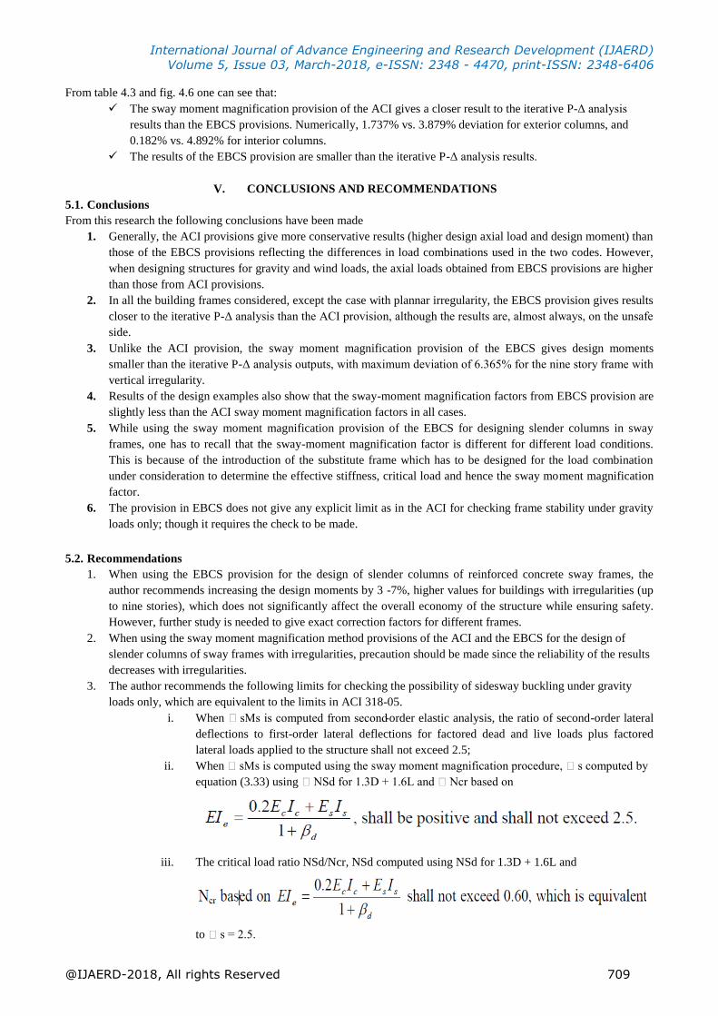
ii. When sMs is computed using the sway moment magnification procedure, s computed by
equation (3.33) using NSd for 1.3D + 1.6L and Ncr based on
iii. The critical load ratio NSd/Ncr, NSd computed using NSd for 1.3D + 1.6L and
to s = 2.5.
International Journal of Advance Engineering and Research Development (IJAERD)
Volume 5, Issue 03, March-2018, e-ISSN: 2348 - 4470, print-ISSN: 2348-6406
@IJAERD-2018, All rights Reserved 710
In i), ii) and iii) above, d shall be taken as the ratio of the total sustained axial loads to the
total axial loads.
iv. As in ACI318-08, the above three checks can be ignored simply by limiting the ratio of the
total moment including second-order effects to first-order moments to 1.40.
EFERENCES
[1]. ACI Committee 318, Building Code Requirements for Structural Concrete (ACI 318-08) and
Commentary, American Concrete Institute, Farmington Hills, MI, 2008.
[2]. ACI Committee 318, Building Code Requirements for Structural Concrete (ACI 318-05) and Commentary (ACI
318R-05), American Concrete Institute, Farmington Hills, MI, 2005.
[3]. Bekele M., “Effective Length and Rigidity of Columns,” ACI JOURNAL, Proceedings V. 84, No. 3, July-August.
1987, pp. 316-329.
[4]. Ethiopian Building Code Standard, EBCS 2-Part 1, Structural Use of Concrete, Ministry of Works and Urban
Development, 1995
[5]. Eurocode 2: Design of concrete structures-Part 1-1: General Rules and Rules for Buildings, 2004.
[6]. MacGregor, J. G., J.K. Wight, Reinforced Concrete Mechanics and Design, 4th edition in SI units, Prentice-Hall,
2006, pp. 522-595
[7]. MacGregor, J. G.; Breen, J. E.; and Pfrang, E. O., “Design of Slender Concrete Columns,” ACI JOURNAL,
Proceedings V. 67, No. 2, Jan. 1970, pp. 6-28.
[8]. MacGregor, J. G., “Design of Slender Concrete Columns-Revisited,” ACI JOURNAL, Proceedings V. 90, No. 3,
May-June. 1993, pp. 302-309.
[9]. Zerayohannes, G., Ethiopian Building Code Standard, EBCS 2-Part 2, Design Aids for Reinforced Concrete
Sections on the Basis of EBCS 2-Part 1, Ministry of Works and Urban Development, 1998.
[10]. Zerayohannes G., “Influence of ACI Provisions for the Design of Columns in Sway Frames on EBCS-2:1995”, ACI
- ETHIOPIA CHAPTER JOURNAL, proceedings, 2009, pp.24-48