international journal of advance engineering and …ijaerd.com/papers/finished_papers/seismic...
TRANSCRIPT

International Journal of Advance Engineering and Research Development
Volume 2,Issue 12,December -2015
@IJAERD-2015, All rights Reserved 185
Scientific Journal of Impact Factor (SJIF): 3.134 E-ISSN (O): 2348-4470 P-ISSN (P): 2348-6406
SEISMIC ANALYSIS OF MULTI-STORIED BUILDING ON SLOPING
GROUND USING SAP 2000
Unnati D Bhagat1, Dharmesh K Bhagat
2, Anand D Patel
3
1Student, Civil Engineering Deprtment, Chhotubhai Gopalbhai Patel institute of Technology,Bardoli, Gujarat
2Associate Professor, Civil Engineering Department, Sarvajanik College of Engineering and Technology,Surat, Gujarat
3Student, Civil Engineering Department, Shree Swami Atamanand Saraswati Institute of Technology,Surat, Gujarat
Abstract — The recent development reveals that there is an unprecedented concentration of residential and commercial
units in a particular area due to shortage of land resulted in vertical development of structures. An analysis and design
of multi-storied building on flat ground is common practice. An attempt is made here to give an idea to analyze a multi-
storied building on sloping ground using software SAP 2000. The shorter column attracts more forces & undergoes
damage, when subjected to earthquakes. In our study, we have considered buildings on plain ground, on 15 degree and
20 degree sloping ground and analyzed the parameters such as Shear Force, Bending Moment and Top Joint
Displacement using software SAP2000.
Keywords- Short-column Effect, Shear Force, Bending Moment, Displacement, SAP2000.
I. INTRODUCTION
Now a days due to increase in population and concentration of them on plain ground its necessary to construct buildings
on sloping ground. Here we completed this study with aim to fulfill this requirement of population by constructing
building on sloping ground by considering all criteria important for this and with the use of important software SAP
2000.
The scarcity of plain ground in hilly areas compels construction activity on sloping ground resulting in various important
buildings such as colleges, hotels and offices erecting on hilly slopes. Since, the behavior of buildings during earthquake
depends upon the distribution of mass and stiffness in both horizontal and vertical planes of the buildings, both of which
vary in case of buildings erecting on slope with irregularity and asymmetry due to step-back and step back-set back
configuration [2]
. The presence of such structures in seismically prone areas makes them exposed to greater shears and
torsion as compared to conventional structure. Current building codes including IS: 1893 (Part 1): 2002 suggest detailed
dynamic analysis of these types of buildings on different soil (hard, medium and soft soil) types [1]
.
In some parts of world, hilly area is more prone to seismic activity; e.g. northeast region of India. In this hilly regions,
traditional material like, the brick, stone masonry and dressed stone masonry, timber reinforced concrete, bamboo, etc.,
which is locally available, are used for the construction of different structures. A scarcity of plain ground in hilly area
compels the construction activity on sloping ground. Hill buildings constructed in masonry with mud mortar/cement
mortar without conforming to seismic codal provisions have proved unsafe and, resulted in loss of life and property when
subjected to earthquake ground motions [5]
.
II. THEORETICAL CONSIDERATIONS
There are different criterion and effects which are necessary to consider at the time of analysis, which are given below:
2.1 Design Criteria:
In case of building with floors capable of providing rigid horizontal diaphragm action, a separate building or any
block of a building between two separate sections shall be analyzed as a whole for seismic force.
In case of buildings where floors are not able to provide the diaphragm action as in above the building frames
behaves independently; and may be analyzed frame by frame with tributary masses for seismic forces.
As per the building height and as per the zone where the building is situated at that place different methods are
recommended for the analysis.
For multistoried buildings, it is assumed that the storey heights are more or less uniform, ranging between 2.7 m
and 3.6 m.
2.2 Planning Criteria:
The influence of site condition.
The structural form.

International Journal of Advance Engineering and Research Development (IJAERD)
Volume 2,Issue 12,December -2015,e-ISSN: 2348 - 4470 , print-ISSN:2348-6406
@IJAERD-2015, All rights Reserved 186
2.3 Short Column Effect:
Short column effect arises when a column in a RC frame building is restricted from moving owing to any obstruction.
The obstruction can be:
(1) Presence of unreinforced masonry infill of partial height of adjoining RC column.
(2) Conditions arising from sloping ground, when some basement columns are shorter than others.
(3) Presence of a mezzanine slab (which meets the columns at an intermediate height between the usual beam-slab
systems of the floors in RC buildings).
(4) Presence of a staircase beam/slab or K-braces on building columns (which meets the columns at an intermediate
height between the usual beam-slab systems of the floors in RC buildings).
(5) Presence of a plinth beam making the height of the column below it to be shorter than that of the column above.
Effective height of column over which it can bend is restricted by adjoining items mentioned above. Since lateral
stiffness of a column is inversely proportional to the cube of its height, this short column effect is more severe when
heights over which the columns are prevented from moving is large (or the unrestricted height of columns is small).
“Figure 1. Short Column Effect on Sloping Ground”
2.4 Seismic Design Requirements:
The basic intent of design theory for earthquake resistant structure is that building should be able to resist minor
earthquakes without damage, resist moderate earthquakes without structural damage but with some non-structural
damage, and resist major earthquakes without collapse but with some structural and non-structural damage.
2.5 Basic Assumptions:
The following assumptions are made in the analysis of earthquake-resistant design of structures:
An earthquake causes impulsive ground motions, which are complex and irregular in character, with each
change in period and amplitude lasting for a small duration. Therefore, resonance of the type visualized under
steady-state sinusoidal excitations will not occur, as it would need time to build up such amplitudes. However,
there are exceptions where resonance-like conditions have been seen to occur between long distance waves and
tall structures founded on deep soft soils.
An earthquake is not likely to occur simultaneously with winds or powerful floods and sea waves. The probability of occurrence of strong earthquake motion along with strong winds and/or maximum sea waves is low. Therefore, it is justified to assume that these hazardous events are not occurring at the same time.
The value of elastic modulus of materials, wherever required, may be taken as the one used for static analysis,
unless a more definite value is available for use in such a condition. It may be noted that the values of modulus
of elasticity for various construction materials display large variations.
III. PROBLEM DEFINATION
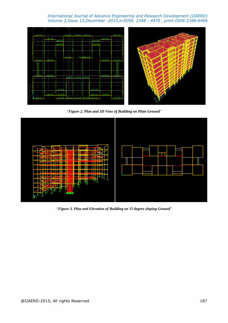
The building having 10 storeys is analyzed for plain ground and sloping ground having slope 15 degree and 20 degree.
International Journal of Advance Engineering and Research Development (IJAERD)
Volume 2,Issue 12,December -2015,e-ISSN: 2348 - 4470 , print-ISSN:2348-6406
@IJAERD-2015, All rights Reserved 187
“Figure 2. Plan and 3D View of Building on Plain Ground”
“Figure 3. Plan and Elevation of Building on 15 degree sloping Ground”

International Journal of Advance Engineering and Research Development (IJAERD)
Volume 2,Issue 12,December -2015,e-ISSN: 2348 - 4470 , print-ISSN:2348-6406
@IJAERD-2015, All rights Reserved 188
“Figure 4. Plan and Elevation of Building on 20 degree sloping Ground”
The table of input data is given below. The seismic analysis of building is carried out using this data and results are
obtained.
“Table 1. Input Data for Building Modeling and Analysis”
Type of Structure Multi-Storey medium rise rigid jointed frame (RC moment resisting frame)
Concrete Grade M25
Steel Grade Fe415
Beam sections
230 mm x 400 mm
250 mm x 450 mm
300 mm x 700 mm
Column Section
For plain Ground:
300 mm x 300 mm (1 to 3 storey)
400 mm x 400 mm ( 4 to 7 storey)
500 mm x 500 mm (8 to 10 storey)
For sloping ground:
350 mm x 750 mm (1 to 3 storey)
400 mm x 600 mm (4 to 7 storey)
500 mm x 500 mm ( 8 to 10 storey)
Slab Thickness 125 mm
Floor Height 3 m
Dead Load Self-Weight
Live Load 3 kN/m2
Earthquake load In both direction x and y
Seismic Zone V
Zone Factor 0.36
Importance Factor 1
Type of Soil Medium Soil
Response Spectra As per IS 1893 (part 1): 2002 for 5% Damping
Seismic Analysis of 3 buildings (Building on plain ground, on 15 degree and on 20 degree sloping ground) models are
run after necessary inputs like section properties, material properties, loads, etc. in software SAP2000.
International Journal of Advance Engineering and Research Development (IJAERD)
Volume 2,Issue 12,December -2015,e-ISSN: 2348 - 4470 , print-ISSN:2348-6406
@IJAERD-2015, All rights Reserved 189
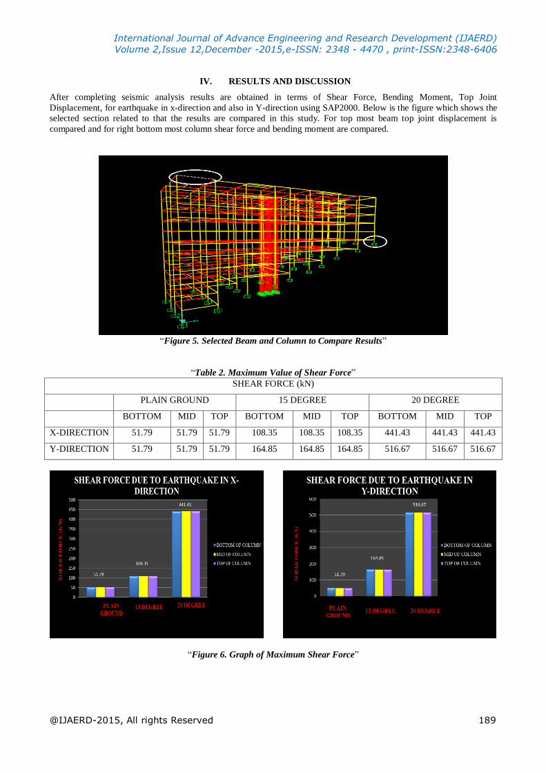
IV. RESULTS AND DISCUSSION
After completing seismic analysis results are obtained in terms of Shear Force, Bending Moment, Top Joint
Displacement, for earthquake in x-direction and also in Y-direction using SAP2000. Below is the figure which shows the
selected section related to that the results are compared in this study. For top most beam top joint displacement is
compared and for right bottom most column shear force and bending moment are compared.
“Figure 5. Selected Beam and Column to Compare Results”
“Table 2. Maximum Value of Shear Force”
SHEAR FORCE (kN)
PLAIN GROUND 15 DEGREE 20 DEGREE
BOTTOM MID TOP BOTTOM MID TOP BOTTOM MID TOP
X-DIRECTION 51.79 51.79 51.79 108.35 108.35 108.35 441.43 441.43 441.43
Y-DIRECTION 51.79 51.79 51.79 164.85 164.85 164.85 516.67 516.67 516.67
“Figure 6. Graph of Maximum Shear Force”

International Journal of Advance Engineering and Research Development (IJAERD)
Volume 2,Issue 12,December -2015,e-ISSN: 2348 - 4470 , print-ISSN:2348-6406
@IJAERD-2015, All rights Reserved 190
“Table 3. Maximum Value of Bending Moment”
BENDING MOMENT (kN.m)
PLAIN GROUND 15 DEGREE 20 DEGREE
BOTTOM MID TOP BOTTOM MID TOP BOTTOM MID TOP
X-DIRECTION 50.03 92.66 130.34 62.67 120.54 166.75 187.03 272.96 413.9
Y-DIRECTION 50.03 92.66 130.34 57.31 123.83 198.97 82.08 192.33 366.75
“Figure 7. Graph of Maximum Bending Moment”
“Table 4. Maximum Value of Top Joint Displacement”
TOP JOINT DISPLACEMENT (mm)
EQ. Force PLAIN GROUND 15 DEGREE 20 DEGREE
X-Direction 19.011445 12.075219 9.245383
Y-Direction 10.863184 8.236761 3.653296
“Figure 8. Graph of Maximum Top Joint Displacement”

International Journal of Advance Engineering and Research Development (IJAERD)
Volume 2,Issue 12,December -2015,e-ISSN: 2348 - 4470 , print-ISSN:2348-6406
@IJAERD-2015, All rights Reserved 191
V. CONCLUSION
The performance of buildings on sloping ground during seismic excitation could prove more vulnerable than the building
on Plain ground. There is increase in the value of Maximum Top Storey Displacement (19.011445 mm) as the height of
building (No. of Storey) increases. The Displacement of building at any point is higher for Building resting on Plain
ground than the sloping ground. The value of Shear Force in columns at ground level (51.79 KN) increases as we
increase the Angle of Slope from 15 degree (108.352 KN) to 20 degree (441.427 KN). Same way the value of Bending
Moment also increases with increase in slope angle. The value of Shear Force in extreme right column is much higher
than other frames in case of sloping ground (Angle of slope 15 & 20 Degree) due to Short Column Effect.
REFERENCES
1. B.C. Punmia, Ashok Kumar Jain, Arun Kumar Jain, “Soil Mechanics and Foundations”, Published by Laxmi
Publications (P) Ltd,2003
2. B.G. Birajdar & S.S. Nalawade, “Seismic Analysis of Buildings Resting on Sloping Ground” 13th World
Conference on Earthquake Engineering, Vancouver, B.C., Canada, Paper No. 1472,2004.
3. Dhiman Basu and Sudhir K. Jam, “Seismic Analysis of Asymmetric Buildings with Flexible Floor Diaphragms”,
Journal of Structural Engineering, Vol. 130, No. 8, 2008, pp. (1169-1176).
4. Fuji, K., Nakano, Y. and Sanada, Y., “Simplified Nonlinear Analysis Procedure for Asymmetric Buildings”, Proc. of
the 13th World Conference on Earthquake Engineering, Vancouver, Canada, Paper No. 149, 2004.
5. IS:1893 (I)-2002., “Criteria for Earthquake Resistant Design of Structures” BIS, New Delhi.
6. Kumar, S. & Paul, D.K., “A Simplified Method for Elastic Seismic Analysis of Hill Buildings”. Journal of
Earthquake Engineering, Vol.2, No.2, pp. (241-266),1998.
7. Kumar, S. and Paul, D.K., “Seismic Analysts of Stepback and Setback Buildings”, Bull. Indian Society of Earthquake
Technology, Paper no. 365, Vol.34, No.2,1997, pp. (47-74).