comparitive study of transmission line tower …ijaerd.com/papers/finished_papers/comparitive...
TRANSCRIPT
International Journal of Advance Engineering and Research Development
Volume 2,Issue 12,December -2015
@IJAERD-2015, All rights Reserved 205
Scientific Journal of Impact Factor (SJIF): 3.134 E-ISSN (O): 2348-4470 P-ISSN (P): 2348-6406
COMPARITIVE STUDY OF TRANSMISSION LINE TOWER IN DIFFERENT
SEISMIC ZONE WITH DIFFERENT CONFIGURATION
Yash N. Patel
1, Jasmin A. Gadhiya
2, Hitesh K. Dhameliya
3, Kosha S. Pachchigar
4 1Civil Department, Chotubhai Gopalbhai Patel Institute of Technology
2 Civil Department, Chotubhai Gopalbhai Patel Institute of Technology
3 Civil Department, Chotubhai Gopalbhai Patel Institute of Technology
4Civil Department, Chotubhai Gopalbhai Patel Institute of Technology
Abstract — There are too many literature papers available for analyzing and designing the transmission line tower.
They show the comparison of different types of towers in form of applicability, economy, stability and different
configuration. Transmission line tower constitute about 28 to 42 percent costs of the transmission lines. The increasing
demand for electrical energy can be met more economical by developing different light weight configurations of
transmission line towers by using hollow steel section instead of convectional section. In present work, the entire
transmission line towers are designed with convectional section.
Keywords- Transmission line tower, Hollow steel section, Dynamic analysis, Staad pro v8i
I. INTRODUCTION
In every country, the need of electric power has continuously increasing so it is necessary to transfer electricity each and
every part of the society. Transmission tower lines are one of most important life-line structures to transfer electricity.
Transmission towers are necessary for the purpose of supplying electricity to various regions of the nation. This has led
to the increase in the building of power stations and consequent increase in power transmission lines from the generating
stations to the different corners where it’s needed. Transmission line should be stable and carefully designed so that they
do not fail during natural disaster. It should also conform to the national and international standard. In the planning and
design of a transmission line, a number of requirements have to be met from both structural and electrical point of view.
From the electrical point of view, the most important requirement is insulation and safe clearances of the power
Transmission tower lines are one of most important life-line structures carrying conductors from the ground. The cross-
section of conductors, the spacing between conductors, and the location of ground wires with respect to the conductors
will decide the design of towers and foundations.
The major components of a transmission line consist of the conductors, ground wires, insulation, towers and foundations.
Most of the time transmission lines are designed for wind and ice in the transverse direction. However, seismic load is
also important because the transmission line towers and the cables may be subjected to higher force and stressed during
ground motion. However, the major concern of the transmission line during high earthquakes may be that the large
displacements do not causes the cables to touch each other or any surrounding objects, causing power failure and
accidents. Therefore, earthquake force is important in design in high earthquake zones of the country. Following are the
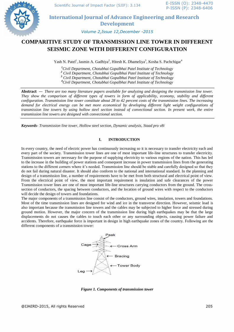
different components of a transmission tower:
Figure 1. Components of transmission tower
International Journal of Advance Engineering and Research Development (IJAERD)
Volume 2,Issue 12,December -2015,e-ISSN: 2348 - 4470 , print-ISSN:2348-6406
@IJAERD-2015, All rights Reserved 206
II. LITERATURE REVIEW
A. Gopiram Addala, D.Neelima Satyam and Ramancharla Pradeep kumar “DYNAMIC ANALYSIS OF
TRANSMISSION TOWERS UNDER STRONG GROUND MOTION’’
The dynamic Behavior of a single transmission tower and transmission towers that are linked by conductors has been
studied by Gopiram Addala, D.Neelima Satyam and Ramancharla Pradeep Kumar in this research work. The model
has been prepared in STAAD PRO and then the seismic analysis of the tower has been performed in SAP2000. The
tower has been subjected to North-ridge strong ground motion (1994) and the Koyna strong ground motion (1967).
Parametric study has been carried out by studying the influence of cable when the force is applied in the cable at different
angles to the cross arms. It was also observed from the analysis that the forces developed when the Northridge (1994)
ground motion is applied in direction of cables are more when compared to forces developed when the ground motion is
applied perpendicular to the conductors. To understand the complete Behavior of transmission tower line it is necessary
to model the cables. The present work can be extended in the future by modelling the cable members and performing the
dynamic nonlinear analysis.
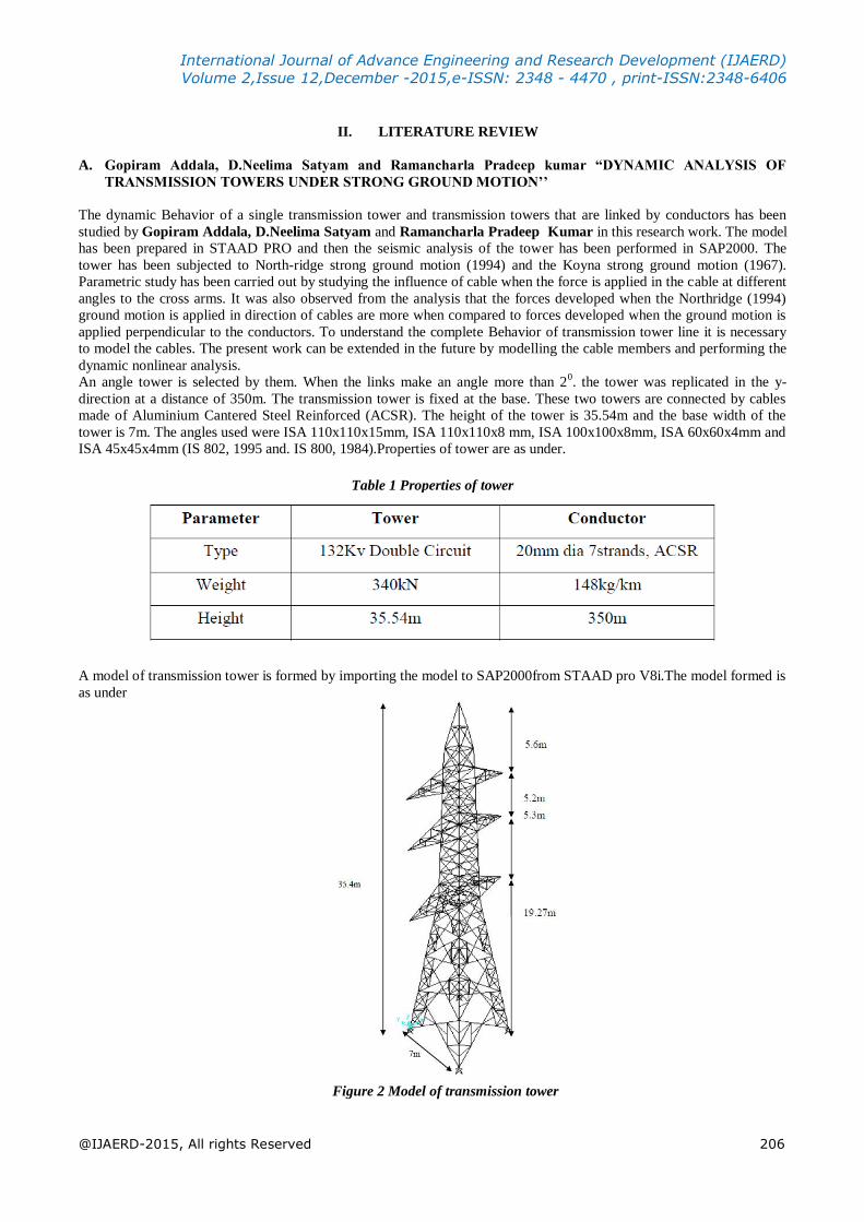
An angle tower is selected by them. When the links make an angle more than 20. the tower was replicated in the y-
direction at a distance of 350m. The transmission tower is fixed at the base. These two towers are connected by cables
made of Aluminium Cantered Steel Reinforced (ACSR). The height of the tower is 35.54m and the base width of the
tower is 7m. The angles used were ISA 110x110x15mm, ISA 110x110x8 mm, ISA 100x100x8mm, ISA 60x60x4mm and
ISA 45x45x4mm (IS 802, 1995 and. IS 800, 1984).Properties of tower are as under.
Table 1 Properties of tower
A model of transmission tower is formed by importing the model to SAP2000from STAAD pro V8i.The model formed is
as under
Figure 2 Model of transmission tower

International Journal of Advance Engineering and Research Development (IJAERD)
Volume 2,Issue 12,December -2015,e-ISSN: 2348 - 4470 , print-ISSN:2348-6406
@IJAERD-2015, All rights Reserved 207
Time period of tower and tower system are obtaines as a result
Table 2 Time period of different modes
B. Ph.D Sun Jianmei and Yang Fuga (2010),” SEISMIC BEHAVIOUR ANALYSIS OF LONG CROSSING
TRANSMISSION TOWER AND TOWER-LINE SYSTEM”
They studied the seismic response of long crossing transmission single tower and tower-line system were systematically
studied by time-history analysis method. The seismic response differences of the displacement, torsion and axial force in
main leg and web member of the single tower and tower-line system are studied. The torsion of tower-line system
becomes much gentler than the single tower with the seismic travel time increases. Because of transmission line, the axial
force of the tower-line system of the bottom of tower leg and web member at the stiffness sudden change are bigger than
single tower. The maximum torsion angle of the single tower fluctuates greatly with the increasing of the peak value of
seismic wave. The torsion angles of the tower-line system change slowly for the line generates the pulling force which
direction is opposite to the tower. The axial forces of the web members, which at the tower legs and the places stiffness
suddenly change, are influenced greatly by the line. it is necessary to consider the coupling effect of the line when the
tower was analyzed under the seismic action, otherwise, the results may be conservative or imprecise.
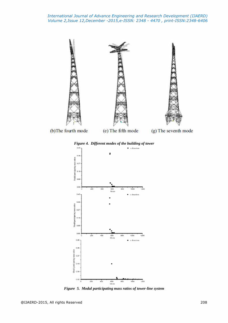
Dynamic analysis of a single tower is carried out. When the modal participating mass ratio of the structure has reached
98% the first 200 mode shapes for single tower were extracted the first 200 mode shapes for single tower were extracted.
The first seven vibration modes are shown in Fig 4.
International Journal of Advance Engineering and Research Development (IJAERD)
Volume 2,Issue 12,December -2015,e-ISSN: 2348 - 4470 , print-ISSN:2348-6406
@IJAERD-2015, All rights Reserved 208
Figure 4. Different modes of the building of tower
Figure 5. Modal participating mass ratios of tower-line system
International Journal of Advance Engineering and Research Development (IJAERD)
Volume 2,Issue 12,December -2015,e-ISSN: 2348 - 4470 , print-ISSN:2348-6406
@IJAERD-2015, All rights Reserved 209
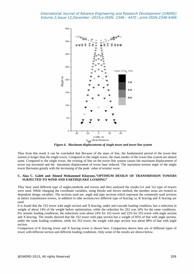
Figure 6. Maximum displacements of single tower and tower line system
Thus from this result it can be concluded that Because of the mass of line, the fundamental period of the tower-line
system is longer than the single tower. Compared to the single tower, the main modes of the tower-line system are almost
same. Compared to the single tower, the existing of line on the tower-line system causes the maximum displacement of
tower top increased and the maximum displacement of tower base reduced. The maximum torsion angle of the single
tower fluctuates greatly with the increasing of the peak value of seismic wave.
C. Alaa C. Galeb and Ahmed Mohammed Khayoon,”OPTIMUM DESIGN OF TRANSMISSION TOWERS
SUBJECTED TO WIND AND EARTHQUAKE LOADING”
They have used different type of angles,methods and towers and then analysed the results.1s1 and 1s2 type of towers
were used. While changing the coordinate variables, using Hooke and Jeeves method, the member areas are treated as
dependent design variables. The sections used are: angle and pipe sections which represent the commonly used sections
in lattice transmission towers, in addition to tube sections.two different type of bracing i.e, K bracing and X bracing are
used.
It is found that the 1S2 tower with angle section and X-bracing, under anti-cascade loading condition, has a reduction in
weight of about 14% of the weight before optimization, while the reduction for 2S2 was 24% for the same conditions.
For seismic loading conditions, the reductions were about 24% for 1S2 tower and 22% for 2S2 tower with angle section
and X-bracing. The results showed that the 1S2 tower with pipe section has a weight of 85% of that with angle section,
under the same loading condition, while for 2S2 tower, the weight with pipe section was about 88% of that with angle
section.
Comparison of K bracing tower and X bracing tower is shown here. Comparison shown here are of different types of
tower with different section and different loading conditions. Only some of the results are shown below.
International Journal of Advance Engineering and Research Development (IJAERD)
Volume 2,Issue 12,December -2015,e-ISSN: 2348 - 4470 , print-ISSN:2348-6406
@IJAERD-2015, All rights Reserved 210
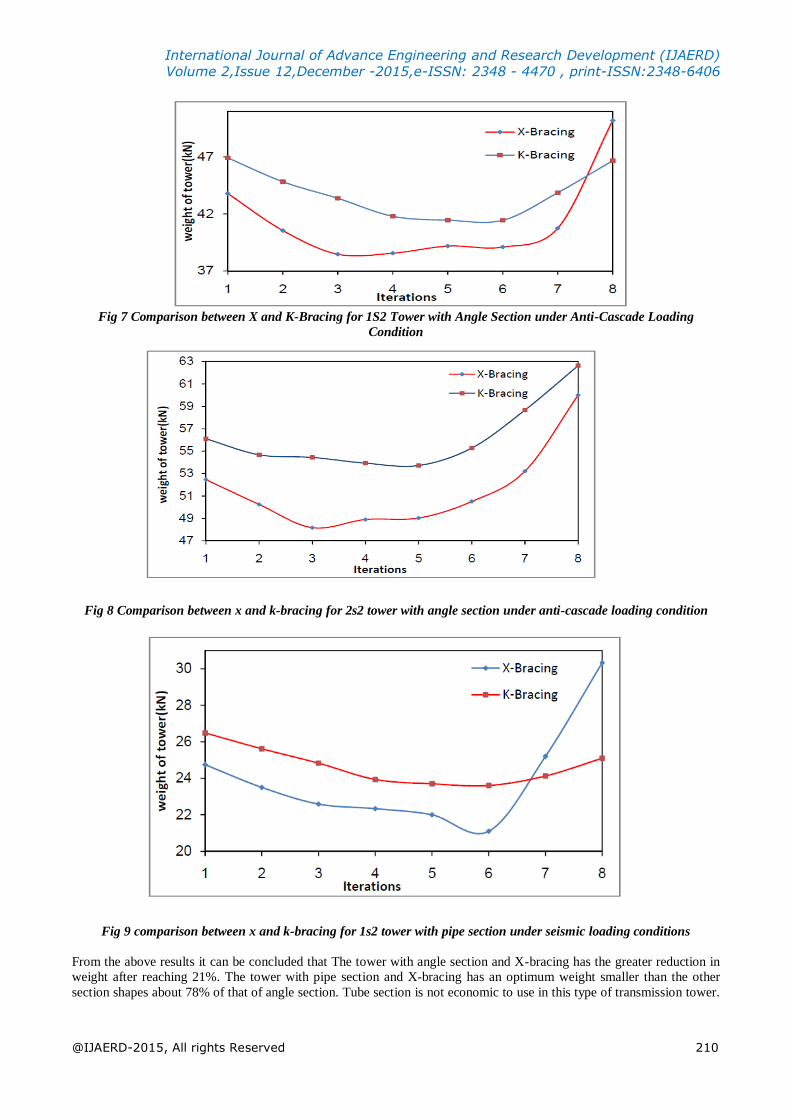
Fig 7 Comparison between X and K-Bracing for 1S2 Tower with Angle Section under Anti-Cascade Loading
Condition
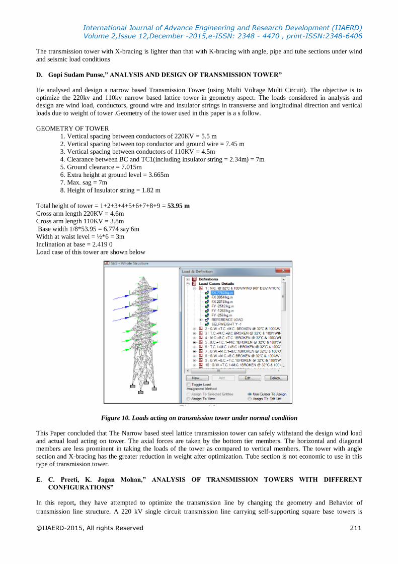
Fig 8 Comparison between x and k-bracing for 2s2 tower with angle section under anti-cascade loading condition
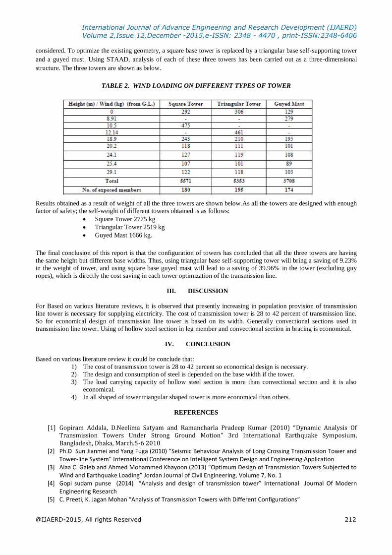
Fig 9 comparison between x and k-bracing for 1s2 tower with pipe section under seismic loading conditions
From the above results it can be concluded that The tower with angle section and X-bracing has the greater reduction in
weight after reaching 21%. The tower with pipe section and X-bracing has an optimum weight smaller than the other
section shapes about 78% of that of angle section. Tube section is not economic to use in this type of transmission tower.
International Journal of Advance Engineering and Research Development (IJAERD)
Volume 2,Issue 12,December -2015,e-ISSN: 2348 - 4470 , print-ISSN:2348-6406
@IJAERD-2015, All rights Reserved 211
The transmission tower with X-bracing is lighter than that with K-bracing with angle, pipe and tube sections under wind
and seismic load conditions
D. Gopi Sudam Punse,” ANALYSIS AND DESIGN OF TRANSMISSION TOWER”
He analysed and design a narrow based Transmission Tower (using Multi Voltage Multi Circuit). The objective is to
optimize the 220kv and 110kv narrow based lattice tower in geometry aspect. The loads considered in analysis and
design are wind load, conductors, ground wire and insulator strings in transverse and longitudinal direction and vertical
loads due to weight of tower .Geometry of the tower used in this paper is a s follow.
GEOMETRY OF TOWER
1. Vertical spacing between conductors of 220KV = 5.5 m
2. Vertical spacing between top conductor and ground wire = 7.45 m
3. Vertical spacing between conductors of 110KV = 4.5m
4. Clearance between BC and TC1(including insulator string = 2.34m) = 7m
5. Ground clearance = 7.015m
6. Extra height at ground level = 3.665m
7. Max. sag = 7m
8. Height of Insulator string = 1.82 m
Total height of tower = 1+2+3+4+5+6+7+8+9 = 53.95 m
Cross arm length 220KV = 4.6m
Cross arm length 110KV = 3.8m
Base width 1/8*53.95 = 6.774 say 6m
Width at waist level = ½*6 = 3m
Inclination at base = 2.419 0
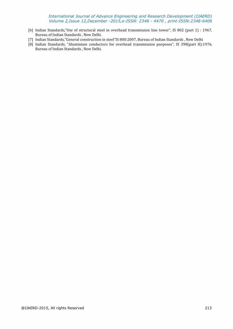
Load case of this tower are shown below
Figure 10. Loads acting on transmission tower under normal condition
This Paper concluded that The Narrow based steel lattice transmission tower can safely withstand the design wind load
and actual load acting on tower. The axial forces are taken by the bottom tier members. The horizontal and diagonal
members are less prominent in taking the loads of the tower as compared to vertical members. The tower with angle
section and X-bracing has the greater reduction in weight after optimization. Tube section is not economic to use in this
type of transmission tower.
E. C. Preeti, K. Jagan Mohan,” ANALYSIS OF TRANSMISSION TOWERS WITH DIFFERENT
CONFIGURATIONS”
In this report, they have attempted to optimize the transmission line by changing the geometry and Behavior of
transmission line structure. A 220 kV single circuit transmission line carrying self-supporting square base towers is
International Journal of Advance Engineering and Research Development (IJAERD)
Volume 2,Issue 12,December -2015,e-ISSN: 2348 - 4470 , print-ISSN:2348-6406
@IJAERD-2015, All rights Reserved 212
considered. To optimize the existing geometry, a square base tower is replaced by a triangular base self-supporting tower
and a guyed must. Using STAAD, analysis of each of these three towers has been carried out as a three-dimensional
structure. The three towers are shown as below.
TABLE 2. WIND LOADING ON DIFFERENT TYPES OF TOWER
Results obtained as a result of weight of all the three towers are shown below.As all the towers are designed with enough
factor of safety; the self-weight of different towers obtained is as follows:
Square Tower 2775 kg
Triangular Tower 2519 kg
Guyed Mast 1666 kg.
The final conclusion of this report is that the configuration of towers has concluded that all the three towers are having
the same height but different base widths. Thus, using triangular base self-supporting tower will bring a saving of 9.23%
in the weight of tower, and using square base guyed mast will lead to a saving of 39.96% in the tower (excluding guy
ropes), which is directly the cost saving in each tower optimization of the transmission line.
III. DISCUSSION
For Based on various literature reviews, it is observed that presently increasing in population provision of transmission
line tower is necessary for supplying electricity. The cost of transmission tower is 28 to 42 percent of transmission line.
So for economical design of transmission line tower is based on its width. Generally convectional sections used in
transmission line tower. Using of hollow steel section in leg member and convectional section in bracing is economical.
IV. CONCLUSION
Based on various literature review it could be conclude that:
1) The cost of transmission tower is 28 to 42 percent so economical design is necessary.
2) The design and consumption of steel is depended on the base width if the tower.
3) The load carrying capacity of hollow steel section is more than convectional section and it is also
economical.
4) In all shaped of tower triangular shaped tower is more economical than others.
REFERENCES
[1] Gopiram Addala, D.Neelima Satyam and Ramancharla Pradeep Kumar (2010) “Dynamic Analysis Of Transmission Towers Under Strong Ground Motion” 3rd International Earthquake Symposium, Bangladesh, Dhaka, March.5-6 2010
[2] Ph.D Sun Jianmei and Yang Fuga (2010) “Seismic Behaviour Analysis of Long Crossing Transmission Tower and Tower-line System” International Conference on Intelligent System Design and Engineering Application
[3] Alaa C. Galeb and Ahmed Mohammed Khayoon (2013) “Optimum Design of Transmission Towers Subjected to Wind and Earthquake Loading” Jordan Journal of Civil Engineering, Volume 7, No. 1
[4] Gopi sudam punse (2014) “Analysis and design of transmission tower” International Journal Of Modern Engineering Research
[5] C. Preeti, K. Jagan Mohan “Analysis of Transmission Towers with Different Configurations”
International Journal of Advance Engineering and Research Development (IJAERD)
Volume 2,Issue 12,December -2015,e-ISSN: 2348 - 4470 , print-ISSN:2348-6406
@IJAERD-2015, All rights Reserved 213
[6] Indian Standards,”Use of structural steel in overhead transmission line tower”, IS 802 (part 1) : 1967, Bureau of Indian Standards , New Delhi.
[7] Indian Standards,”General construction in steel”IS 800:2007, Bureau of Indian Standards , New Delhi [8] Indian Standards, ”Aluminium conductors for overhead transmission purposes”, IS 398(part II):1976,
Bureau of Indian Standards , New Delhi.