installation, operation and maintenance manual - skf.com12-28531/rs232 operating manual.pdf · the...
TRANSCRIPT

Read this manual before installing, operating or maintaining this actuator. Failure to follow safety precautions and instructions could cause actuator failure and result in serious injury, death or property damage.
Installation, operation and maintenance manual

2
L531
8,29
71E
· Ju
ne 2
010
SKF is a registered trademark of the SKF Group.
© SKF 2010The contents of this publication are the copyright of the publisher and may not be reproduced (even extracts)unless prior written permission is granted. Every care has been taken to ensure the accuracy of the information contained in this publication but no liability can be accepted for any loss or damage whether direct, indirect or consequential arising out of the useof the information contained herein.
3
L531
8,29
71E
· Ju
ne 2
010
1 Introduction ............................................................................................................4 Content ....................................................................................................................4 Validity scope ..........................................................................................................4 Target group ...........................................................................................................4 Presentation conventions .....................................................................................4 Safety advice ...........................................................................................................4 Other advice ............................................................................................................5 Code examples .......................................................................................................5 Cross-references ....................................................................................................6 Referencing of diagram details ............................................................................6
2 Safety .......................................................................................................................7 General safety advice ............................................................................................7
3 Technical overview .................................................................................................9 Connection cable ....................................................................................................9 Physical layer ..........................................................................................................9 Data link layer ........................................................................................................9 Network layer .........................................................................................................10 Transport layer .......................................................................................................10 Telegram structure ................................................................................................10
4 Communication protocol .......................................................................................11 Command set .........................................................................................................11 Communication error and acknowledge codes .................................................13 Abbreviations used ................................................................................................13 Data list ...................................................................................................................13 Function list ............................................................................................................19 SCU Error code ......................................................................................................20 Control of drives .....................................................................................................22 Function definition .................................................................................................22 Setting of motion parameters .............................................................................22 Read-out of information .......................................................................................22 Position data ...........................................................................................................22
5 Communication examples ....................................................................................23 Example: Move to position and read current position with SCP11 parameterization ..............................................................................23
6 Code examples .......................................................................................................25 Checksum calculation ............................................................................................25
7 Structure definitions ..............................................................................................28
Table of Contents
i

4
L531
8,29
71E
· Ju
ne 2
010
This chapter contains information regarding the structure and the organization ofthe operation manual which simplifies use of the operation manual and makes itpossible to obtain rapid access to desired information.
This operation manual contains a description of the RS232 serial interface of the SCUcontrol unit. Please note that the RS232 interface is an option with the SCU control unitand must be ordered on the basis of the type key.
Validity scope
The information in this operation manual concern the serial interface for the SCU controlunit with the following identification:
Manufacturer: SKF Actuation System (Liestal) AGProduct name: SCU control unit with serial RS232 interfaceType designation: SCUxx-xxxxx1-xxxxYear of manufacture: after 2007 with Firmwave version V2B0CE identification: in accordance with technical documentation
Target group
This manual is intended for development engineers who have the necessary professionalknowledge to be able to develop control software for the operation of this product.
In this operation manual we employ certain abbreviations and markings to identify textsections or advice.
Safety advice
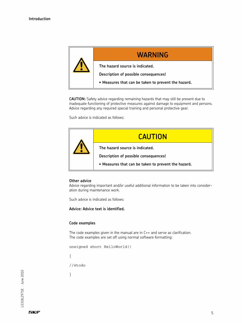
WARNING: Safety advice to notify of danger of irreparable damage to equipment andpersons based on hazard analyses. This includes advice as regards protective measuresand any required special training and personal protective gear.
Such advice is indicated as follows:
1. Introduction
Content
Presentation conventions
5
L531
8,29
71E
· Ju
ne 2
010
CAUTION: Safety advice regarding remaining hazards that may still be present due toinadequate functioning of protective measures against damage to equipment and persons.Advice regarding any required special training and personal protective gear.
Such advice is indicated as follows:
Other adviceAdvice regarding important and/or useful additional information to be taken into consider-ation during maintenance work.
Such advice is indicated as follows:
Advice: Advice text is identified.
Code examples
The code examples given in the manual are in C++ and serve as clarification.The code examples are set off using normal software formatting:
unsigned short HelloWorld()
{
//@todo
}
Introduction
WARNINGThe hazard source is indicated.
Description of possible consequences!
CAUTIONThe hazard source is indicated.
Description of possible consequences!

6
L531
8,29
71E
· Ju
ne 2
010
Cross-references
Cross-references to sections in other areas of the operation manual are bracketed. Theycontain the corresponding header text and page number.
Cross-references are indicated as follows:
( Cross-references, page 6)
Referencing of diagram details
Details in diagrams are sequentially lettered clockwise and correspondingly referencedin the text.
Introduction
7
L531
8,29
71E
· Ju
ne 2
010
Safety advice in this manual is differentiated according to applicability as follows.
General safety advice Such safety advice applies in general and is to be taken into consideration on replacement of any assembly group. They are given in the section General Safety Advice .
Special safety advice Such safety advice is only relevant for some assembly groups. This type of advice is found in the replacement description for the assembly group concerned.
2. Safety
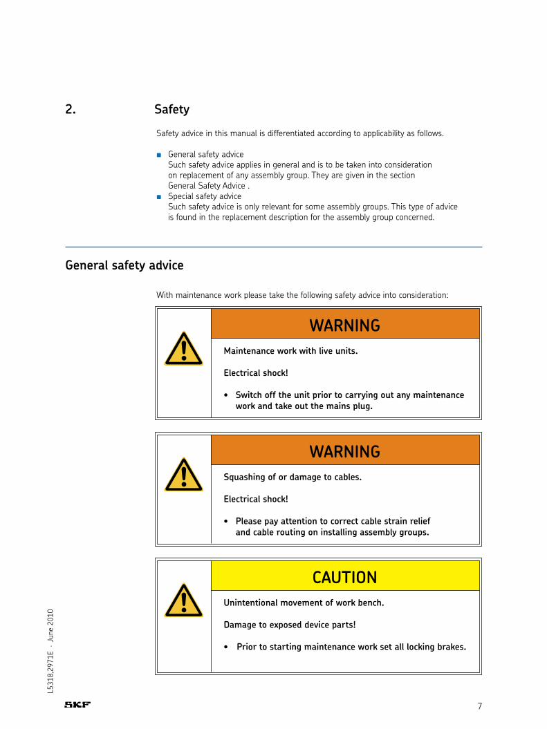
With maintenance work please take the following safety advice into consideration:
General safety advice
WARNING
Electrical shock!
work and take out the mains plug.
WARNINGSquashing of or damage to cables.
Electrical shock!
and cable routing on installing assembly groups.
CAUTIONUnintentional movement of work bench.
Damage to exposed device parts!
8
L531
8,29
71E
· Ju
ne 2
010
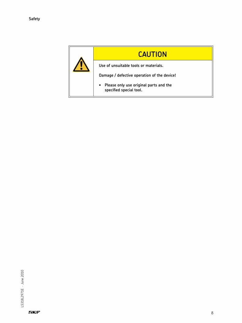
CAUTIONUse of unsuitable tools or materials.
Damage / defective operation of the device!
specified special tool.
Safety

9
L531
8,29
71E
· Ju
ne 2
010
The basic technical characteristics of the serial interface are given in this chapter.
Note: If the remote user does not provide a mains supply according to medical standards (safety according to ENE60601-1) the final application has to be grounded to ensure a correct operation of RS 232 interface.
Recommended connection cable: ZKA-160658-3000
Electrical characteristics in accordance with RS232 definitionHalf duplexBi-directionalBaud rate: With standard control units the baud rate is set to 38400.
With customized control units the baud rate may be set to the following values: 9600, 19200, 38400,
Plug: 9-pole SUB-D (female)The control lines are not used. However, DTR and RTS must be switched on as
permanently active because they supply the RS232 converter in the control unit. Instead of the DTR and RTS signals a separate power source of 5.5…15 VDC/30mA can be connected (+ on pin 4 DTR or pin 7 RTS and – on pin 5 GND)
Connection allocation:
One start bit8 data bits (LSB first)One stop bitNo parity bitNo handshake
3. Technical overview
Connection cable
Physical layer
Data link layer
2. RxD3. TxD4. DTR5. GND7. RTS
10
L531
8,29
71E
· Ju
ne 2
010
Technical overview
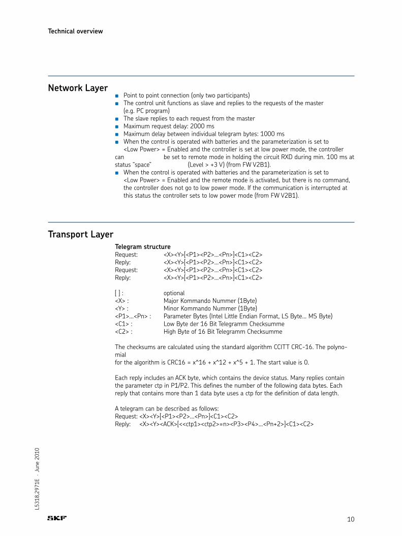
Point to point connection (only two participants)The control unit functions as slave and replies to the requests of the master
(e.g. PC program)The slave replies to each request from the masterMaximum request delay: 2000 msMaximum delay between individual telegram bytes: 1000 msWhen the control is operated with batteries and the parameterization is set to
<Low Power> = Enabled and the controller is set at low power mode, the controller can be set to remote mode in holding the circuit RXD during min. 100 ms at status “space” (Level > +3 V) (from FW V2B1).
When the control is operated with batteries and the parameterization is set to <Low Power> = Enabled and the remote mode is activated, but there is no command, the controller does not go to low power mode. If the communication is interrupted at this status the controller sets to low power mode (from FW V2B1).
Telegram structureRequest: <X><Y>[<P1><P2>…<Pn>]<C1><C2>Reply: <X><Y>[<P1><P2>…<Pn>]<C1><C2>Request: <X><Y>[<P1><P2>…<Pn>]<C1><C2>Reply: <X><Y>[<P1><P2>…<Pn>]<C1><C2>
[ ] : optional<X> : Major Kommando Nummer (1Byte)<Y> : Minor Kommando Nummer (1Byte)<P1>…<Pn> : Parameter Bytes (Intel Little Endian Format, LS Byte... MS Byte)<C1> : Low Byte der 16 Bit Telegramm Checksumme<C2> : High Byte of 16 Bit Telegramm Checksumme
The checksums are calculated using the standard algorithm CCITT CRC-16. The polyno-mialfor the algorithm is CRC16 = x^16 + x^12 + x^5 + 1. The start value is 0.
Each reply includes an ACK byte, which contains the device status. Many replies containthe parameter ctp in P1/P2. This defines the number of the following data bytes. Eachreply that contains more than 1 data byte uses a ctp for the definition of data length.
A telegram can be described as follows:Request: <X><Y>[<P1><P2>…<Pn>]<C1><C2>Reply: <X><Y><ACK>[<<ctp1><ctp2>=n><P3><P4>…<Pn+2>]<C1><C2>
Network Layer
Transport Layer
11
L531
8,29
71E
· Ju
ne 2
010
4. Communication protocol
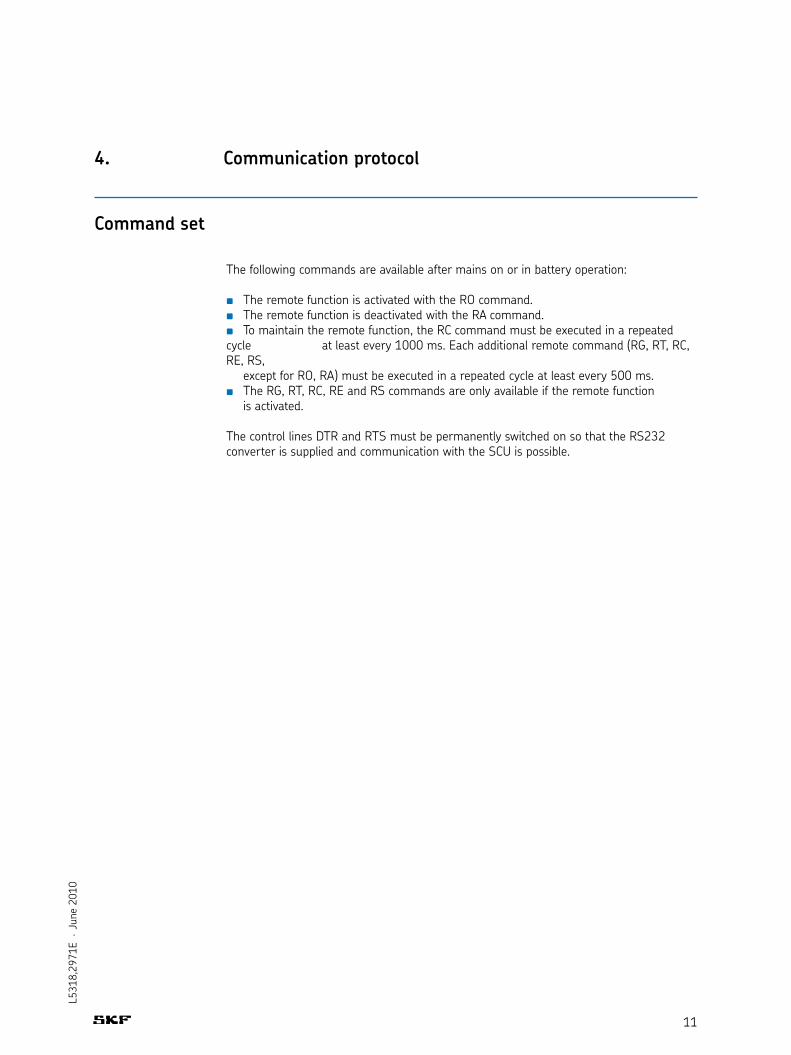
The following commands are available after mains on or in battery operation:
The remote function is activated with the RO command. The remote function is deactivated with the RA command.To maintain the remote function, the RC command must be executed in a repeated
cycle at least every 1000 ms. Each additional remote command (RG, RT, RC, RE, RS, except for RO, RA) must be executed in a repeated cycle at least every 500 ms.
The RG, RT, RC, RE and RS commands are only available if the remote function is activated.
The control lines DTR and RTS must be permanently switched on so that the RS232 converter is supplied and communication with the SCU is possible.
Command set
12
L531
8,29
71E
· Ju
ne 2
010
Communication protocol
Cmd
<X>Y
>
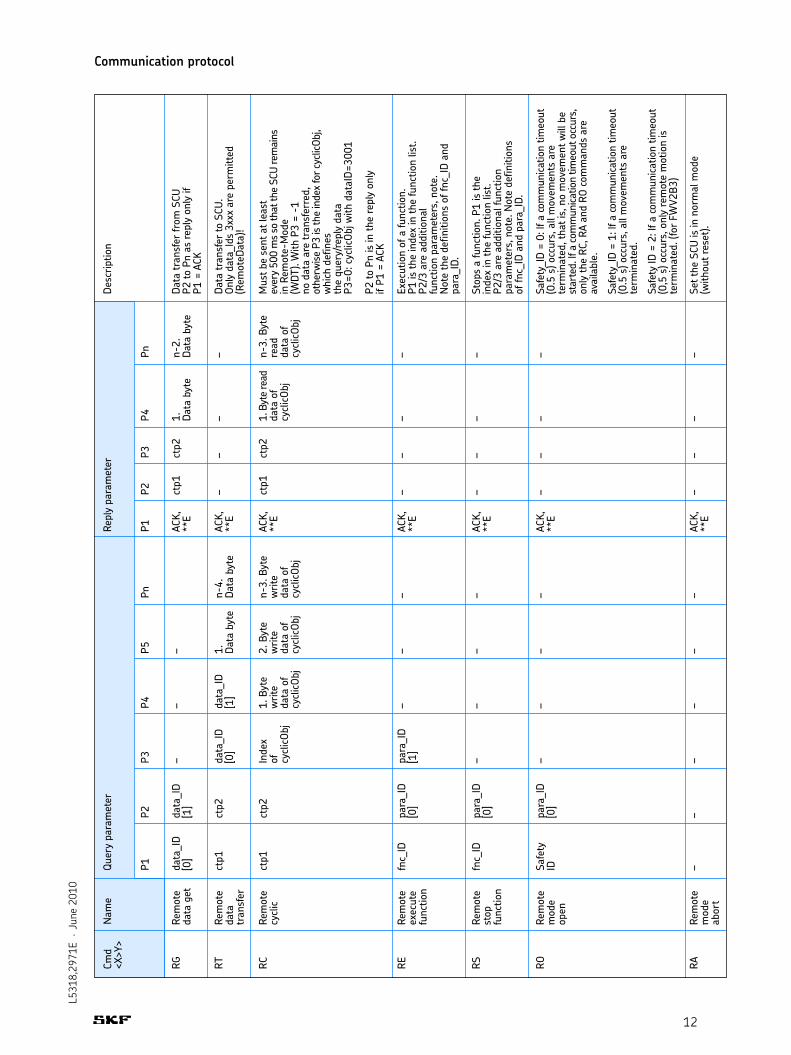
RG RT RC RE
Rem
ote
data
get
Rem
ote
data
tran
sfer
Rem
ote
cycl
ic
Rem
ote
exec
ute
func
tion
data
_ID
[0]
ctp1
ctp1
fnc_
ID
data
_ID
[1]
ctp2
ctp2
para
_ID
[0]
– data
_ID
[0]
Inde
xof cy
clicO
bj
para
_ID
[1]
– data
_ID
[1]
1. B
yte
writ
eda
ta o
fcy
clicO
bj
–
– 1. Data
byt
e
2. B
yte
writ
eda
ta o
fcy
clicO
bj
–
n-4.
Data
byt
e
n-3.
Byt
ew
rite
data
of
cycl
icObj
–
ACK,
**E
ACK,
**E
ACK,
**E
ACK,
**E
ctp1
– ctp1
–
ctp2
– ctp2
–
1. Data
byt
e
– 1. B
yte
read
data
of
cycl
icObj
–
n-2.
Data
byt
e
– n-3.
Byt
ere
adda
ta o
fcy
clicO
bj
–
Data
tran
sfer
from
SCU
P2 to
Pn
as re
ply
only
ifP1
= A
CK
Data
tran
sfer
to S
CU.
Only
dat
a_Id
s 3x
xx a
re p
erm
itted
(Rem
oteD
ata)
!
Mus
t be
sent
at l
east
ever
y 50
0 m
s so
that
the
SCU
rem
ains
in R
emot
e-M
ode
(WDT
). W
ith P
3 =
-1no
dat
a ar
e tr
ansf
erre
d,ot
herw
ise P
3 is
the
inde
x fo
r cyc
licOb
j,w
hich
def
ines
the
quer
y/re
ply
data
P3=0
: cyc
licOb
j with
dat
aID=
3001
P2 to
Pn
is in
the
repl
y on
lyif
P1 =
ACK
Exec
utio
n of
a fu
nctio
n.P1
is th
e in
dex
in th
e fu
nctio
n lis
t.P2
/3 a
re a
dditi
onal
func
tion
para
met
ers,
not
e.N
ote
the
defin
ition
s of
fnc_
ID a
ndpa
ra_I
D.
Nam
eQu
ery
para
met
er
P1P2
P3P4
P5Pn
Repl
y pa
ram
eter
P1P2
P3P4
Pn
Desc
riptio
n
RSRe
mot
est
opfu
nctio
n
fnc_
IDpa
ra_I
D[0
]–
––
–AC
K,**
E–
––
–St
ops
a fu
nctio
n. P
1 is
the
inde
x in
the
func
tion
list.
P2/3
are
add
ition
al fu
nctio
npa
ram
eter
s, n
ote.
Not
e de
finiti
ons
of fn
c_ID
and
par
a_ID
.
RORe
mot
em
ode
open
Safe
tyID
para
_ID
[0]
––
––
ACK,
**E
––
––
Safe
ty_I
D =
0: If
a co
mm
unica
tion
timeo
ut(0
.5 s
) occ
urs,
all
mov
emen
ts a
rete
rmin
ated
, tha
t is,
no
mov
emen
t will
be
star
ted.
If a
com
mun
icatio
n tim
eout
occ
urs,
only
the
RC, R
A an
d RO
com
man
ds a
reav
aila
ble.
Safe
ty_I
D =
1: If
a co
mm
unica
tion
timeo
ut(0
.5 s
) occ
urs,
all
mov
emen
ts a
rete
rmin
ated
.
Safe
ty ID
= 2
: If a
com
mun
icatio
n tim
eout
(0,5
s) o
ccur
s, o
nly
rem
ote
mot
ion
iste
rmin
ated
. (fo
r FW
V2B3
)
RARe
mot
em
ode
abor
t
––
––
––
ACK,
**E
––
––
Set t
he S
CU is
in n
orm
al m
ode
(with
out r
eset
).

13
L531
8,29
71E
· Ju
ne 2
010
Communication protocol
Communication error and acknowledge codes
Abbreviations used
Data list
Code Hex Dec Name Description
ACK 06 6 Command Query accepted acknowledged CSE 80 128 Checksum error Error in the telegram checksum
PDE 81 129 Parameter data Error in the telegram data bytes error
PCE 82 130 Parameter count Incorrect counter level of the telegram data bytes error
ICE 83 131 Invalid command Unknown command code error
PE 84 132 Permission error Command not possible with current SCU mode/state
Code Value Description
ctp Dyn Number of following telegram bytes
data_ID Dyn Index in data list (see data list table)
fnc_id Dyn Index for function list (see function list table)
para_id Dyn Additional parameters depend on function (see function list table)
Primary Secondary Data Name Data type Commentcollection collection indexindex index
0000 0001 Firmware Info STRING size = 31 Byte Name Version CS
0002 Configuration info STRING size = 36 Byte Name Version CS
The specific settings and the status of the control unit can be queried via the data list(RG command). Both individual values and entire blocks can be queried. The values withcollection index 3000 can be described with the RT command.

14
L531
8,29
71E
· Ju
ne 2
010
Communication protocol
Primary Secondary Data Name Data type Commentcollection collection indexindex index
0000 0010 0011 Actual_Position Actuator 1 INT32 Unit: Encoder flank (count) 0012 Actual_Position Actuator 2 INT32 0013 Actual_Position Actuator 3 INT32 0014 Actual_Position Actuator 4 INT32 0015 Actual_Position Actuator 5 INT32 0016 Actual_Position Actuator 6 INT32
0020 Actual_State_Binary Inputs 1...4 UINT8 Logic level Bit 0: binary input 1 (0 = not active/ 1 = active) Bit 1: binary input 2 (0 = not active/ 1 = active) Bit 2: binary input 3 (0 = not active/ 1 = active) Bit 3: binary input 4 (0 = not active/ 1 = active)
Input level Bit 4: binary input 1 (0 = not active/ 1 = active) Bit 5: binary input 2 (0 = not active/ 1 = active) Bit 6: binary input 3 (0 = not active/ 1 = active) Bit 7: binary input 4 (0 = not active/ 1 = active)
0030 0031 Actual_State_Analogue_Input_1 UINT16 Data: 0...600
0032 Actual_State_Analogue_Input_2 UINT16 Resolution 0.01V
0033 Actual_State_Analogue_Input_3 UINT16 Range: 0…6.00V
0034 Actual_State_Analogue_Input_4 UINT16 0040 Actual_State_Keys UINT32 Bit 0: K1 … Bit 19: K20 Bit 20 … Bit 31 not used (0 = open / 1 = closed)
0060 0061 Number_cycle_off_on_off_Relay_in UINT32 A1
0062 Number_cycle_off_on_off_Relay_in UINT32 A2
0063 Number_cycle_off_on_off_Relay_in UINT32 A3
0064 Number_cycle_off_on_off_Relay_in UINT32 A4
0065 Number_cycle_off_on_off_Relay_in UINT32 A5
0066 Number_cycle_off_on_off_Relay_in UINT32

15
L531
8,29
71E
· Ju
ne 2
010
Primary Secondary Data Name Data type Commentcollection collection indexindex index
0000 0070 0071 Number_cycle_off_on_off_Relay_out UINT32 A1
0072 Number_cycle_off_on_off_Relay_out UINT32 A2
0073 Number_cycle_off_on_off_Relay_out UINT32 A3
0074 Number_cycle_off_on_off_Relay_out UINT32 A4
0075 Number_cycle_off_on_off_Relay_out UINT32 A5
0076 Number_cycle_off_on_off_Relay_out A6
0080 0081 Number_Actuator error A1 UINT32 count 2 byte: number of 0082 Number_Actuator error A2 UINT32 actuator error 1 byte: number of peak 0083 Number_Actuator error A3 UINT32 current occurrence 1 byte: number of short circuit 0084 Number_Actuator error A4 UINT32 occurence
0085 Number_Actuator error A5 UINT32 0086 Number_Actuator error A6 UINT32
008F Number_Total_Over_Current UINT32 0090 0091 Cumulated_Stroke A1 UINT32 Unit: Encoder flank
0092 Cumulated_Stroke A2 UINT32 0093 Cumulated_Stroke A3 UINT32
0094 Cumulated_Stroke A4 UINT32
0095 Cumulated_Stroke A5 UINT32 0096 Cumulated_Stroke A6 UINT32
00A0 00A1 Current A1 UINT16 Data: 0...1000 Unit: fixed-point 0.1A 00A2 Current A2 UINT16 Range: 0..100A 00A3 Current A3 UINT16
00A4 Current A4 UINT16 00A5 Current A5 UINT16 00A6 Current A6 UINT16
Communication protocol
16
L531
8,29
71E
· Ju
ne 2
010
Primary Secondary Data Name Data type Commentcollection collection indexindex index
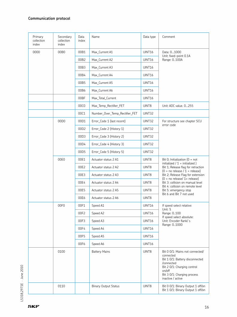
0000 00B0 00B1 Max_Current A1 UINT16 Data: 0...1000 Unit: fixed-point 0.1A 00B2 Max_Current A2 UINT16 Range: 0..100A
00B3 Max_Current A3 UINT16 00B4 Max_Current A4 UINT16 00B5 Max_Current A5 UINT16
00B6 Max_Current A6 UINT16
00BF Max_Total_Current UINT16
00C0 Max_Temp_Rectifier_FET UINT8 Unit: ADC value. 0...255
00C1 Number_Over_Temp_Rectifier_FET UINT32
00D0 00D1 Error_Code 1 (last recent) UINT32 For structure see chapter SCU error code 00D2 Error_Code 2 (History 1) UINT32 00D3 Error_Code 3 (History 2) UINT32 00D4 Error_Code 4 (History 3) UINT32
00D5 Error_Code 5 (History 5) UINT32
00E0 00E1 Actuator status 2 A1 UINT8 Bit 0; Initialization (0 = not initialized / 1 = initialized ) 00E2 Actuator status 2 A2 UINT8 Bit 1; Release flag for retraction (0 = no release / 1 = release) 00E3 Actuator status 2 A3 UINT8 Bit 2; Release Flag for extension (0 = no release/ 1= release) 00E4 Actuator status 2 A4 UINT8 Bit 3: collision on manual level Bit 4: collision on remote level 00E5 Actuator status 2 A5 UINT8 Bit 5: emergency stop Bit 6 and Bit 7 not used 00E6 Actuator status 2 A6 UINT8
00F0 00F1 Speed A1 UINT16 If speed select relative: Unit: % 00F2 Speed A2 UINT16 Range: 0..100 If speed select absolute: 00F3 Speed A3 UINT16 Unit: Encoder flank/ s Range: 0..1000 00F4 Speed A4 UINT16
00F5 Speed A5 UINT16
00F6 Speed A6 UINT16
0100 Battery Mains UINT8 Bit 0 0/1: Mains not connected/ connected Bit 1 0/1: Battery disconnected /connected Bit 2 0/1: Charging control on/off Bit 3 0/1: Charging process inactive / active
0110 Binary Output Status UINT8 Bit 0 0/1: Binary Output 1 off/on Bit 1 0/1: Binary Output 1 off/on
Communication protocol

17
L531
8,29
71E
· Ju
ne 2
010
Primary Secondary Data Name Data type Commentcollection collection indexindex index
0000 0120 LED HS UINT8 Bit 0 0/1: LED1 hand switch off/on Bit 1 0/1: LED2 hand switch off/on
0130 LED LB UINT8 Bit 0 0/1: LED1 locking box off/on Bit 1 0/1: LED2 locking box off/on … Bit 7 0/1: LED8 locking box off/on
0140 Buzzer UINT8 Bit 0 0/1: Buzzer off/on
0150 Sensor Supply UINT8 Bit 0 0/1: Sensor Supply off/on
0162 Lock Status UINT16 Bit 0 0/1: Funktion 0 unlocked/ locked Bit 1 0/1: Funktion 1 unlocked/ locked ... Bit 9 0/1: Funktion 10 unlocked/ locked
0164 Battery voltage UINT16 Unit: Fixed-point 0,1V Range: 0... 40,0 V
0165 Locking Box detected UINT8 0..2 locking box
0166 User UINT8 User 1..4
0170 0171 Actuator Status 1 A 1 UINT8 Bit 0 0/1 drive unavailable/ drive available 0172 Actuator Status 1 A 2 UINT8 Bit 1 0/1: signal limit_in_out inactive/aktive 0173 Actuator Status 1 A 3 UINT8 Bit 2 0/1: signal switch 1 inactive/active Bit 3 0/1: signal switch 2 inactive/active 0174 Actuator Status 1 A 4 UINT8 Bit 4 0/1: motion inactive/active Bit 5 0/1: in position not reached/reached 0175 Actuator Status 1 A 5 UINT8 Bit 6 0/1: out position Bit 7 0/1 Stroke not done/done 0176 Actuator Status 1 A 6 UINT8 Bit 7 0/1 Stroke not done/done
Configuration data items
1000 1010 1011- Conversion factor A 1-6 FLOAT 1016
User position data items
2000 2001 UserPositionData A 1 STRUCT Structure definition according to chapter 7. Structure definitions, 2002 UserPositionData A 2 STRUCT page 28: ACTUATOR_POSITIONS 2003 UserPositionData A 3 STRUCT 2004 UserPositionData A 4 STRUCT 2005 UserPositionData A 5 STRUCT
2006 UserPositionData A 6 STRUCT
Communication protocol

18
L531
8,29
71E
· Ju
ne 2
010
Primary Secondary Data Name Data type Commentcollection collection indexindex index
Remote data itemsStored in volatile register. Initialized after reset with preset values.
3000 3001 CyclicObj 1 UINT16[12] With the CyclicObj definition the data transferred to and from the SCU with each RC 3002 CyclicObj 2 UINT16[12] command can be determined. The data indices set in the first 6 bytes (para[0..5] define the 3003 CyclicObj 3 UINT16[12] data to be sent to the SCU, (write data) and the data indices set in the last 6 bytes 3004 CyclicObj 4 UINT16[12] (para[6..11]) define the data that will be returned by the SCU (read data). A data index 3005 CyclicObj 5 UINT16[12] of –1 means no data transfer. All data can be read by the SCU, but only data with the indices 3xxx can be written. Default value: -1
3010 3011- Remote Speed F1-10 UINT16 Default value: function speed 301A from configuration. If speed select relative: Unit: % Range: 0..100 If speed select absolute: Unit: Encoder flank/ s Range: 0..1000 3020 3021- Remote Position A1-6 INT32 Default value: memory 1 / user 3026 1 position of UserPositionData (DynamicConfiguration) Unit: Encoder flank
Communication protocol

19
L531
8,29
71E
· Ju
ne 2
010
Communication protocol
Function list
Func-ID Value (dez.) Used by Description Para_ID[x] command
F1...F10 0...9 RE, RS Motion function Para_ID[0] according to (depends on parameterization) Tab 4-1 Para_ID[1] = -1
F11 10 RE, RS Buzzer (from FW V2B1) Para_ID[0] = -1 Para_ID[1] = -1
F17 16 RE, RS Binary Output 1 (from FW V2B1) Para_ID[0] = -1 Para_ID[1] = -1
F18 17 RE, RS Binary Output 2 (from FW V2B1) Para_ID[0] = -1 Para_ID[1] = -1 F20 19 RE, RS Emergency stop (from FW V2B1) Para_ID[0] = -1 Para_ID[1] = -1 F21 20 RE, RS Operating unit Para_ID[0] = -1 Led1 (from FW V2B1) Para_ID[1] = -1
F22 21 RE, RS Operating unit Para_ID[0] = -1 Led2 (from FW V2B1) Para_ID[1] = -1
Used for func_ID Para_ID[1] Value (dez.) Description
F1-F10 (only with motion_direction 0-9 0: Undefined direction (no motion)RE command) 1: Move to position In 2: Move to position Out 3: Move to position Mem1 4: Move to position Mem2 5: Move to position Mem3 6: Move to position Mem4 7: Move to position Intermediate In 8: Move to position Intermediate Out 9: Move to Remote Position
F1-F10 (only with motion_stop 0-1 0: Fast Start/stop (start/stop rampRS command) not considered) 1: Soft Start/stop (start/stop ramp considered)
Tab. 4-1 Parameter depends on function:
The unused parameters in the telegram structure are to be set to –1 (unused_para).The function of F1 – F10 is established in the control unit parameterization. A functioncan be assigned from one to six drives. If more than one drive is assigned to a functionthe drives may be coordinated among themselves:
Simultaneous running in the same or opposite direction (simultaneous starting / stopping, but no position synchronization)
Synchronized simultaneous running in the same direction or in the opposite direction (controlled position synchronization)
The second case can also be parameterized with a constant difference between the drives.

20
L531
8,29
71E
· Ju
ne 2
010
Bit in error field Cause Condition for appearance Reaction
Bit 1 CRC error with ROM test. – Motions are stopped and the control unit Faulty ROM carries out a reset.
Bit 2 Error with RAM test. Faulty – Motions are stopped and the control unit RAM. carries out a reset. Bit 3 Error with CPU test. Faulty – Motions are stopped and the control unit CPU. carries out a reset.
Bit 4 STACK overrun detected. – Motions are stopped (fast stop) and the control unit carries out a reset..
Bit 5 Programm sequence error. – Motions are stopped (fast stop) and the Watchdog reset. control unit carries out a reset..
Bit 6 Error with hand switch test. Only if hand switch is Motions are stopped (fast stop) Short detected in hand switch. parameterized as “safe” Bit 7 Error with binary inputs. Short Only if binary inputs are Motions are stopped (fast stop) detected between binary parameterized as safe inputs and no analogue input is parameterized.
Bit 8 Error with relay and FET tests. Test performed at start of Motion not executed. Faulty relay or FET. motion. Bit 9 – – –
Bit 10 Error with communication – Motions stopped (fast stop). with MoveEnable controller. No reply from MoveEnable controller.
Bit 11 Error with MoveEnable output – Motions stopped (fast stop). test. The MoveEnable controller output is incorrect. Bit 12 Overtemperature detected at – Motions stopped (fast stop). rectifier or FET.
Bit 13 Switching off due to excessive – Motions stopped. discharge of battery (Fast stop). Control unit switches itself off.
Bit 14 Total current is exceeded If motion in process. Motions stopped (fast stop). Bit reset in the next motion.
Communication protocol
SCU Error code
21
L531
8,29
71E
· Ju
ne 2
010
Communication protocol
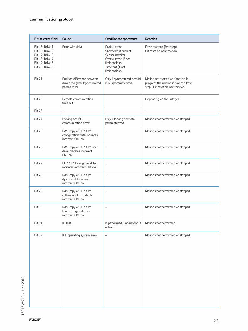
Bit in error field Cause Condition for appearance Reaction
Bit 15: Drive 1 Error with drive Peak current Drive stopped (fast stop). Bit 16: Drive 2 Short circuit current Bit reset on next motion.Bit 17: Drive 3 Sensor monitorBit 18: Drive 4 Over current (if not Bit 19: Drive 5 limit position)Bit 20: Drive 6 Time out (if not limit position)
Bit 21 Position difference between Only if synchronized parallel Motion not started or if motion in drives too great (synchronized run is parameterized. progress the motion is stopped (fast parallel run) stop). Bit reset on next motion.
Bit 22 Remote communication – Depending on the safety ID time out
Bit 23 – – –
Bit 24 Locking box I2C Only if locking box safe Motions not performed or stopped communication error parameterized
Bit 25 RAM copy of EEPROM – Motions not performed or stopped configuration data indicates incorrect CRC on
Bit 26 RAM copy of EEPROM user – Motions not performed or stopped data indicates incorrect CRC on
Bit 27 EEPROM locking box data – Motions not performed or stopped indicates incorrect CRC on
Bit 28 RAM copy of EEPROM – Motions not performed or stopped dynamic data indicate incorrect CRC on
Bit 29 RAM copy of EEPROM – Motions not performed or stopped calibration data indicate incorrect CRC on
Bit 30 RAM copy of EEPROM – Motions not performed or stopped HW settings indicates incorrect CRC on
Bit 31 IO Test Is performed if no motion is Motions not performed active.
Bit 32 IDF operating system error – Motions not performed or stopped
22
L531
8,29
71E
· Ju
ne 2
010
Communication protocol
Control of individual drives occurs via functions F1-F10. A function is activated via theRE command and thus one or more drives started. Each RE command must be stoppedwith an RS, even if the drive is stopped after reaching the end position.
Function definition
Please obtain the function definitions from the parameterization dokumentation for thecontrol unit.
Setting of motion parameters
The motion parameters of speed and target position can be set via the indices 3011 to301A or 3021 to 3026. The speed applies to the selected function, the target position isconnected with individual drives. Motion is started with the RE command and parameter 9.
Speed is to be given in percentages (0-100%) or increments. This depends on theparameterization of the control unit. For standard control units the speed is set in percent-ages. The lower threshold on which a drive is set into motion depends on the typeof drive and load. The speed can be changed during motion. The control unit adjusts thespeed according to the soft start ramp.
Operating states and information can be read from the control unit via the RG command.Values can be queried individually or blockwise.
Position data
The indices 0011 to 0016 will return current position. The grouping index 0010 returnsthe position of all 6 possible 6 drives. The position can be calculated in mm from the valuesof end position and hub length.
Control of drives
Read-out of information

23
L531
8,29
71E
· Ju
ne 2
010
5. Communication examples
SCP11 parameterization
With the SCP11 parameterization all drives are set for individual operation. Drive 1 isassigned to function 1, drive 2 to function 2 and so on. In this way the drives can be con-trolled individually using functions 1-6.
Routine:
Communication mode open with RO (Safety ID)Set remote position of drive 1Start movement of drive 1Read status of drive 1. Check if movement is activated.Read current position of drive 1During the entire routine a cyclically repeated RC command communication must
occur at least every 500 ms. The RC communication functions as a watchdog. If the RC communication should fail, the SCU will stop all drives in motion and deactivate the remote mode.
Before the first command is sent to the SCU an RC communication must also have taken place (activation of remote mode)
Communication mode closed with RA
Tab. 5-1 Periodic RC communication without any data transfer in this case(without CyclObj):
Cmd Name Request parameter Reply parameter
P1 P2 P3 P4 P5 Pn P1 P2 P3 P4
RO Remote 00 – – – – – ACK, – – – Mode open **E
Cmd Name Request parameter Reply parameter
P1 P2 P3 P4 P5 Pn P1 P2 P3 P4 P5 P6 P7
RC Remote 01 00 -1 – – – ACK, – – – – – – cyclic **E
Cmd Name Request parameter Reply parameter
P1 P2 P3 P4 P5 P6 P1 P2 P3 P4 Pn
RT Remote 04 00 11 30 01 00 ACK, – – – data **E transfer
– – – Safe communication mode open
Tab. 5-2 Setting of remote speed of drive 1 to value 100h with RT command (data index 3011):

24
L531
8,29
71E
· Ju
ne 2
010
Cmd Name Request parameter Reply parameter
P1 P2 P3 P4 P5 Pn P1 P2 P3 P4 Pn
RE Remote 09 00 -1 – – – ACK, – – – – execute function **E
Cmd Name Request parameter Reply parameter
P1 P2 P3 P4 P5 Pn P1 P2 P3 P4 P5 P6 P7
RG Remote 71 01 – – – – ACK, 01 00 Sta- data get **E tus
Cmd Name Request parameter Reply parameter
P1 P2 P3 P4 P5 Pn P1 P2 P3 P4 P5 P6 P7
RG Remote 11 00 – – – – ACK, 04 00 1. 2. 3. 4. data get **E Daten Daten Daten Daten byte byte byte byte
Cmd Name Request parameter Reply parameter
P1 P2 P3 P4 P5 Pn P1 P2 P3 P4
RA Remote – – -1 – – ACK, – – – Mode abord **E
Tab. 5-3 Drive to the Remote Position with actuator 1 without start/stop ramp. Starts with the RE command (Data index 0):
Tab. 5-4 Request status of drive 1 with RG command (Data index 0171):
Status bit 4 is set so long as the motion is active.
Tab. 5-5 Request current position of drive 1 with RG command (data index 0011):
Close communication mode
Communication examples

25
L531
8,29
71E
· Ju
ne 2
010
6. Code examples
The checksum is determined using the standard CCITT CRC16 algorithm. The polynomialis CRC16 = x16 + x12 + x5 + 1, the starting value is 0.
The calculation of the CRC checksum makes heavy use of the processor. In order toreduce this a CRC table should ideally be used.
Tab. 6-1 Code example 1: CRC table
Code example 2 is an example of CRC checksum determination using the table. The 2bytes returned must be connected to the command.
Checksum calculation
static const unsigned short CRC_TABLE[256] = { 0x0000 0x1021 0x2042 0x3063 0x4084 0x50A5 0x60C6 0x70E7 0x8108 0x9129 0xA14A 0xB16B 0xC18C 0xD1AD 0xE1CE 0xF1EF 0x1231 0x0210 0x3273 0x2252 0x52B5 0x4294 0x72F7 0x62D6 0x9339 0x8318 0xB37B 0xA35A 0xD3BD 0xC39C 0xF3FF 0xE3DE 0x2462 0x3443 0x0420 0x1401 0x64E6 0x74C7 0x44A4 0x5485 0xA56A 0xB54B 0x8528 0x9509 0xE5EE 0xF5CF 0xC5AC 0xD58D 0x3653 0x2672 0x1611 0x0630 0x76D7 0x66F6 0x5695 0x46B4 0xB75B 0xA77A 0x9719 0x8738 0xF7DF 0xE7FE 0xD79D 0xC7BC 0x48C4 0x58E5 0x6886 0x78A7 0x0840 0x1861 0x2802 0x3823 0xC9CC 0xD9ED 0xE98E 0xF9AF 0x8948 0x9969 0xA90A 0xB92B 0x5AF5 0x4AD4 0x7AB7 0x6A96 0x1A71 0x0A50 0x3A33 0x2A12 0xDBFD 0xCBDC 0xFBBF 0xEB9E 0x9B79 0x8B58 0xBB3B 0xAB1A 0x6CA6 0x7C87 0x4CE4 0x5CC5 0x2C22 0x3C03 0x0C60 0x1C41 0xEDAE 0xFD8F 0xCDEC 0xDDCD 0xAD2A 0xBD0B 0x8D68 0x9D49 0x7E97 0x6EB6 0x5ED5 0x4EF4 0x3E13 0x2E32 0x1E51 0x0E70 0xFF9F 0xEFBE 0xDFDD 0xCFFC 0xBF1B 0xAF3A 0x9F59 0x8F78 0x9188 0x81A9 0xB1CA 0xA1EB 0xD10C 0xC12D 0xF14E 0xE16F 0x1080 0x00A1 0x30C2 0x20E3 0x5004 0x4025 0x7046 0x6067 0x83B9 0x9398 0xA3FB 0xB3DA 0xC33D 0xD31C 0xE37F 0xF35E 0x02B1 0x1290 0x22F3 0x32D2 0x4235 0x5214 0x6277 0x7256 0xB5EA 0xA5CB 0x95A8 0x8589 0xF56E 0xE54F 0xD52C 0xC50D 0x34E2 0x24C3 0x14A0 0x0481 0x7466 0x6447 0x5424 0x4405 0xA7DB 0xB7FA 0x8799 0x97B8 0xE75F 0xF77E 0xC71D 0xD73C 0x26D3 0x36F2 0x0691 0x16B0 0x6657 0x7676 0x4615 0x5634 0xD94C 0xC96D 0xF90E 0xE92F 0x99C8 0x89E9 0xB98A 0xA9AB 0x5844 0x4865 0x7806 0x6827 0x18C0 0x08E1 0x3882 0x28A3 0xCB7D 0xDB5C 0xEB3F 0xFB1E 0x8BF9 0x9BD8 0xABBB 0xBB9A 0x4A75 0x5A54 0x6A37 0x7A16 0x0AF1 0x1AD0 0x2AB3 0x3A92 0xFD2E 0xED0F 0xDD6C 0xCD4D 0xBDAA 0xAD8B 0x9DE8 0x8DC9 0x7C26 0x6C07 0x5C64 0x4C45 0x3CA2 0x2C83 0x1CE0 0x0CC1 0xEF1F 0xFF3E 0xCF5D 0xDF7C 0xAF9B 0xBFBA 0x8FD9 0x9FF8 0x6E17 0x7E36 0x4E55 0x5E74 0x2E93 0x3EB2 0x0ED1 0x1EF0 };

26
L531
8,29
71E
· Ju
ne 2
010
Code examples
unsigned short CalculateChecksum(const unsigned char* pAdr, int len){ if (len < 0) { ASSERT(FALSE); return 0; } unsigned short crc = 0; while (len--) { crc = static_cast<unsigned short>(CRC_TABLE[((crc >> 8) ^ *pAdr++) & 0xFF] ^ (crc << 8)); } return crc;}
Tab. 6-2 Code example 3: Calculation of checksum using the table
27
L531
8,29
71E
· Ju
ne 2
010
Code examples
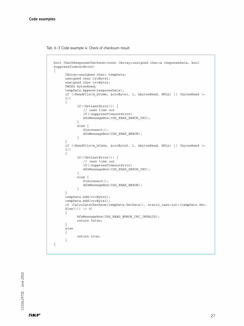
Tab. 6-3 Code example 4: Check of checksum result
bool CheckResponseChecksum(const CArray<unsigned char>& responseData, boolsuppressTimeoutError){ CArray<unsigned char> tempData; unsigned char crcByte1; unsigned char crcByte2; DWORD bytesRead; tempData.Append(responseData); if (!ReadFile(m_hComm, &crcByte1, 1, &bytesRead, NULL) || (bytesRead != 1)) { if(!GetLastError()) { // case time out if(!suppressTimeoutError) AfxMessageBox(IDS_READ_ERROR_CRC); } else { Disconnect(); AfxMessageBox(IDS_READ_ERROR); } } if (!ReadFile(m_hComm, &crcByte2, 1, &bytesRead, NULL) || (bytesRead != 1)) { if(!GetLastError()) { // case time out if(!suppressTimeoutError) AfxMessageBox(IDS_READ_ERROR_CRC); } else { Disconnect(); AfxMessageBox(IDS_READ_ERROR); } } tempData.Add(crcByte2); tempData.Add(crcByte1); if (CalculateChecksum(tempData.GetData(), static_cast<int>(tempData.Get- Size())) != 0) { AfxMessageBox(IDS_READ_ERROR_CRC_INVALID); return false; } else { return true; }}

28
L531
8,29
71E
· Ju
ne 2
010
struct ACTUATOR_POSITIONSstruct { INT32 Position_Memory_1[USER_1; INT32 Position_Memory_2[USER_1]; INT32 Position_Memory_3[USER_1]; INT32 Position_Memory_4[USER_1]; INT32 Position_Intermediate_In[USER_1]; INT32 Position_Intermediate_Out[USER_1];
INT32 Position_Memory_1[USER_2; INT32 Position_Memory_2[USER_2]; INT32 Position_Memory_3[USER_2]; INT32 Position_Memory_4[USER_2]; INT32 Position_Intermediate_In[USER_2]; INT32 Position_Intermediate_Out[USER_2];
INT32 Position_Memory_1[USER_3; INT32 Position_Memory_2[USER_3]; INT32 Position_Memory_3[USER_3]; INT32 Position_Memory_4[USER_3]; INT32 Position_Intermediate_In[USER_3]; INT32 Position_Intermediate_Out[USER_3]; INT32 Position_Memory_1[USER_4; INT32 Position_Memory_2[USER_4]; INT32 Position_Memory_3[USER_4]; INT32 Position_Memory_4[USER_4]; INT32 Position_Intermediate_In[USER_4]; INT32 Position_Intermediate_Out[USER_4]; INT32 Position_Virtual_Limit_In; INT32 Position_Virtual_Limit_Out; };
ACTUATOR_POSITIONS positions[ACTUATOR_COUNT];
7. Structure definitions