instrumentation and control systems and software important
TRANSCRIPT
1
Date: 29 June 2021
IAEA SAFETY STANDARDS for protecting people and the environment
Instrumentation and Control Systems and
Software Important to Safety for Research
Reactors
DS509H
DRAFT SAFETY GUIDE
A revision of Safety Guide SSG-37
Step 10: Second Internal
Review of Draft Publication
Reviewed in NSOC
(Shaw/Asfaw/Nikolaki)
2
CONTENTS
1. INTRODUCTION ....................................................................................................................... 4
Background ......................................................................................................................................... 4
Objective ............................................................................................................................................. 5
Scope ................................................................................................................................................... 5
Structure .............................................................................................................................................. 5
2. SAFETY CLASSIFICATION OF INSTRUMENTATION AND CONTROL SYSTEMS FOR
A RESEARCH REACTOR..................................................................................................................... 6
classification of instrumentation and contol systems .......................................................................... 8
Design, construction, commissioning, operation and maintenance of instrumentation and control
systems ................................................................................................................................................ 8
3. OVERALL INSTRUMENTATION AND CONTROL SYSTEM ARCHITECTURE FOR A
RESEARCH REACTOR ........................................................................................................................ 9
The application of the defence in depth concept to instrumentation and control systems at a research
reactor ................................................................................................................................................ 10
Independence of instrumentation and control systems at a research reactor ..................................... 10
Consideration of common cause failure in instrumentation and control systems at a research reactor
........................................................................................................................................................... 11
Architectural design of the instrumentation and control system for a research reactor .................... 11
4. DESIGN GUIDELINES FOR INSTRUMENTATION AND CONTROL SYSTEMS FOR A
RESEARCH REACTOR ...................................................................................................................... 13
Design basis for instrumentation and control systems for a research reactor ................................... 14
Design for reliability of instrumentation and control systems for a research reactor ........................ 15
Design considerations for ageing of instrumentation and control systems at a research reactors ..... 19
Consideration of the safety and security interface in the design of instrumentation and control systems
for a research reactor ......................................................................................................................... 20
Equipment Qualification of instrumentation and control systems for aresearch reactor ................... 21
Testing and testability of instrumentation and control systems for a research reactor ...................... 23
Maintainability of instrumentation and control systems at a research reactor .................................. 27
Safety assessment of instrumentation and control systems at a research reactor .............................. 28
Safety system settings for instrumentation and control systems at a research reactor ...................... 29
Identification and verification of instrumentation and control systems important to safety at a research
reactor ................................................................................................................................................ 29
Design of instrumentation and control systems at a research reactor for design extension conditions
........................................................................................................................................................... 30
5. SYSTEM SPECIFIC DESIGN GUIDELINES FOR INSTRUMENTATION AND CONTROL
SYSTEMS FOR A RESEARCH REACTOR ....................................................................................... 31
Sensing devices for instrumentation and control systems at a research reactor ................................ 31
Reactor protection system ................................................................................................................. 32
3
Other instrumentation and control systems important to safety of a research reactor ....................... 34
Design of research reactor control rooms .......................................................................................... 35
Control systems for irradiation facilities and experimental devices at a research reactor ................. 36
Voice communication system at a research reactor .......................................................................... 36
Fire detection systems and fire extinguishing systems at a research reactor ..................................... 37
Power supplies of instrumentation and control systems at a research reactor ................................... 38
6. OPERATION OF INSTRUMENTATION AND CONTROL SYSTEMS DURING THE
OPERATION OF AT A RESEARCH REACTOR ............................................................................... 39
Instrumentation and control systems and operational limits and conditions at a research reactor .... 39
Control of access to instrumentation and control systems important to safety at a research reactor 39
Maintenance, periodic testing, and inspection of instrumentation and control systems at a research
reactor ................................................................................................................................................ 40
Provisions for removal from service of instrumentation and control systems for testing or maintenance
........................................................................................................................................................... 41
Instrumentation and control systems during Extended shutdown of a research reactor .................... 41
7. HUMAN FACTORS ENGINEERING AND HUMAN–MACHINE INTERFACES AT A
RESEARCH REACTOR ...................................................................................................................... 41
Criteria for human factors engineering and design of human–machine interfaces at a research reactor
........................................................................................................................................................... 42
Human factors engineering for research reactor Control rooms ....................................................... 43
8. COMPUTER BASED SYSTEMS AND SOFTWARE AT A RESEARCH REACTOR ........ 44
Design considerations for computer based systems and software at a research reactor .................... 45
Project planning for computer based systems and software at a research reactor ............................. 47
Specification of computer based system REQUIREMENTS at a research reactor ........................... 49
Software requirements for a research reactor .................................................................................... 50
Software design for a research reactor .............................................................................................. 50
Software implementation for a research reactor ................................................................................ 51
Verification and analysis of software for a research reactor ............................................................. 51
Third party assessment of software for a research reactor ................................................................ 53
Computer system integration at a research reactor ............................................................................ 53
9. CONFIGURATION MANAGEMENT OF INSTRUMENTATION AND CONTROL
SYSTEMS AT A RESEARCH REACTOR ......................................................................................... 55
10. MODIFICATION AND MODERNIZATION OF INSTRUMENTATION AND CONTROL
SYSTEMS AT A RESEARCH REACTOR ......................................................................................... 56
REFERENCES ...................................................................................................................................... 60
ANNEX ................................................................................................................................................. 62
CONTRIBUTORS TO DRAFTING AND REVIEW ........................................................................... 68

4
1. INTRODUCTION
BACKGROUND
1.1. Requirements for the safety of research reactors, with particular emphasis on their design and
operation, are established in IAEA Safety Standards Series No. SSR-3, Safety of Research Reactors [1].
1.2. This Safety Guide provides recommendations on design and operation of instrumentation and
control systems for research reactors.
1.3. This Safety Guide was developed in parallel with seven other Safety Guides on the safety of
research reactors, as follows:
• IAEA Safety Standards Series No. DS509A, Commissioning of Research Reactors [2];
• IAEA Safety Standards Series No. DS509B, Maintenance, Periodic Testing and Inspection of
Research Reactors [3];
• IAEA Safety Standards Series No. DS509C, Core Management and Fuel Handling for Research
Reactors [4];
• IAEA Safety Standards Series No. DS509D, Operational Limits and Conditions and Operating
Procedures for Research Reactors [5];
• IAEA Safety Standards Series No. DS509E, The Operating Organization and the Recruitment,
Training and Qualification of Personnel for Research Reactors [6];
• IAEA Safety Standards Series No. DS509F, Radiation Protection and Radioactive Waste
Management in the Design and Operation of Research Reactors [7];
• IAEA Safety Standards Series No. SSG-10 (Rev. 1), Ageing Management for Research Reactors
[8];
1.4. Additional recommendations on the safety of research reactors are provided in IAEA Safety
Standards Series Nos SSG-20 (Rev. 1), Safety Assessment of Research Reactors and Preparation of the
Safety Analysis Report [9] and SSG-24 (Rev. 1), Safety in the Utilization and Modification of Research
Reactors [10].
1.5. The terms used in this Safety Guide are to be understood as defined and explained in the IAEA
Safety Glossary [11].
1.6. This Safety Guide supersedes IAEA Safety Standards Series No. SSG-37, Instrumentation and
Control Systems and Software Important to Safety for Research Reactors1.
1 INTERNATIONAL ATOMIC ENERGY AGENCY, Instrumentation and Control Systems and Software
Important to Safety for Research Reactors, IAEA Safety Standards Series No. SSG-37, IAEA, Vienna (2015).

5
OBJECTIVE
1.7. The objective of this Safety Guide is to provide recommendations on instrumentation and control
systems and software important to safety for research reactors, including instrumentation and control
system architecture and associated components, from sensors to actuators, operator interfaces and
auxiliary equipment, to meet the relevant requirements of SSR-3 [1], in particular Requirements 49, 51
and 52.
1.8. The recommendations provided in this Safety Guide are aimed at operating organizations of
research reactors, regulatory bodies and other organizations involved in a research reactor project,
including suppliers of instrumentation and control systems.
SCOPE
1.9. This Safety Guide is primarily intended for use for heterogeneous, thermal spectrum research
reactors having a power rating of up to several tens of megawatts. For research reactors of higher power,
specialized reactors (e.g. fast spectrum reactors) and reactors having specialized facilities (e.g. hot or
cold neutron sources, high pressure and high temperature loops) additional guidance may be needed.
For such research reactors, the recommendations provided in IAEA Safety Standards Series No. SSG-
39, Design of Instrumentation and Control Systems for Nuclear Power Plants [12] might be more
suitable. Homogeneous reactors and accelerator driven systems are out of the scope of this publication.
1.10. Research reactors with a low hazard potential having a power rating of up to several tens of
kilowatts and critical assemblies and subcritical assemblies might need a less comprehensive approach.
While all recommendations in this Safety Guide are to be considered, some might not be applicable to
such research reactors, critical assemblies and subcritical assemblies (see paras 2.15–2.17 and
Requirement 12 of SSR-3 [1], and IAEA Safety Standards Series No. SSG-22, Use of a Graded
Approach in the Application of the Safety Requirements for Research Reactors [13]).
1.11. In this Safety Guide, subcritical assemblies will be mentioned separately only if a specific
recommendation is not relevant for, or is applicable only to, subcritical assemblies.
1.12. The recommendations apply to both the design and the configuration management of
instrumentation and control systems and software for new research reactors and the modernization of
the instrumentation and control systems and software of existing research reactors.
1.13. This Safety Guide also provides recommendations and guidance on human factors engineering
and human–machine interfaces for instrumentation and control systems and software important to
safety.
STRUCTURE
1.14. Section 2 provides recommendations on the safety classification of instrumentation and control
functions, systems, and components. Section 3 provides recommendations on how instrumentation and
6
control systems are to be arranged into a hierarchy. Sections 4 and 5 provide recommendations on
meeting design requirements for instrumentation and control systems. Recommendations on the
operational aspects of instrumentation and control systems are provided in Section 6. Section 7 expands
on the recommendations provided in Section 4 in the area of human–machine interfaces. Section 8
provides recommendations on design aspects and other aspects of computer based systems and software.
Section 9 provides recommendations on configuration management for instrumentation and control
systems. Section 10 provides recommendations on the modification and modernization of
instrumentation and control systems. The Annex identifies instrumentation and control systems that can
be used in a research reactor.
2. SAFETY CLASSIFICATION OF INSTRUMENTATION AND
CONTROL SYSTEMS FOR A RESEARCH REACTOR
2.1. Instrumentation and control functions, systems and components may be classified into two
categories: those that are important to safety and those that are not important to safety (see Fig. 1 and
the Annex). Instrumentation and control systems not important to safety are those that are used to
support the operation of the facility, while having no impact on the safety of the reactor.
2.2. Functions, systems and components important to safety are those that contribute to the following
main safety functions (see Requirement 7 of SSR-3 [1]):
(a) Control of reactivity, safely shutting down the reactor and maintaining it in a safe shutdown
condition in operational states and in accident conditions and post-accident conditions;
(b) Removal of heat from the reactor and from the fuel storage, in all operational states and accident
conditions;
(c) Confinement of radioactive material, shielding against radiation and control of planned radioactive
releases, as well as limitation of accidental radioactive releases.
2.3. Systems and components important to safety are further categorized into safety systems, safety
features for design extension conditions, and safety related systems [11], as follows:
(a) Safety systems consist of the protection system, the safety actuation systems and the safety system
support features;
(b) Safety features for design extension conditions are items that are designed to perform a safety
function for or that have a safety function in design extension conditions;
(c) Safety related systems are systems important to safety that are not part of a safety system, such as
systems for monitoring the availability of safety systems.

7
Note: CCTV — closed circuit television; HVAC — heating, ventilation and air-conditioning; I&C —
instrumentation and control.
FIG. 1. Examples of instrumentation and control systems of a research reactor classified in
accordance with their importance to safety.
8
2.4. A graded approach to the application of safety requirements for a research reactor is required: see
Requirement 12 of SSR-3 [1]. For instrumentation and control systems important to safety, the extent
to which a graded approach is applied should be clearly justified in the safety analysis report (the factors
to be considered are listed in para. 2.17 of SSR-3 [1]). Recommendations on the application of the
graded approach are provided in SSG-22 [13].
CLASSIFICATION OF INSTRUMENTATION AND CONTOL SYSTEMS
2.5. Paragraph 6.29 of SSR-3 [1] states (footnote omitted):
“The method for classifying the safety significance of items important to safety shall be based
primarily on deterministic methods complemented, where appropriate, by probabilistic methods
(if available), with due account taken of factors such as:
(a) The safety function(s) to be performed by the item;
(b) The consequences of failure to perform a safety function;
(c) The frequency with which the item will be called upon to perform a safety function;
(d) The time following a postulated initiating event at which, or the period for which, the
item will be called upon to perform a safety function.”
2.6. An instrumentation and control system where a spurious failure, or failure on demand, might
cause an initiating event or make the consequences of a postulated initiating event worse, should be
classified in a high safety class. A similar approach should be applied to the instrumentation and control
aspects of reactivity control systems whose failure might lead to accident conditions.
2.7. The instrumentation and control functions for all facility states of the research reactor should be
identified. For a research reactor, the instrumentation and control functions necessary to mitigate the
consequences of design extension conditions could be assigned to a lower safety class than the functions
necessary for the control of anticipated operational occurrences and design basis accidents to reach a
safe state.
DESIGN, CONSTRUCTION, COMMISSIONING, OPERATION AND MAINTENANCE
OF INSTRUMENTATION AND CONTROL SYSTEMS
2.8. All instrumentation and control systems and equipment should be designed, constructed,
commissioned, operated and maintained in such a manner that their specification, verification and
validation, and their quality and reliability are commensurate with their safety classification. The
specifications should consider sufficient functional margins for their safety system design. These
margins should be verified at both component level and system level by testing and analysis.
2.9. Paragraph 6.30 of SSR-1 [1] states:
9
“The design shall be such as to ensure that any interference between items important to safety
will be prevented, and in particular that any failure of items important to safety in a system in a
lower safety class will not propagate to a system in a higher safety class.”
All instrumentation and control systems performing functions important to safety should have
appropriately designed interfaces with systems and equipment of different safety classes (by using
appropriate physical or logical barriers) in order to meet the above requirement. Equipment that prevents
such a propagation of failure should be treated as being in the higher class.
2.10. The safety class of an instrumentation and control system should be the same as the highest safety
class of the systems or equipment that it controls.
3. OVERALL INSTRUMENTATION AND CONTROL SYSTEM
ARCHITECTURE FOR A RESEARCH REACTOR
3.1. The instrumentation and control system architecture should support all the instrumentation and
control functions necessary to ensure the safety of the research reactor. Requirement 49 of SSR-3 [1]
states:
“Instrumentation shall be provided for a research reactor facility for monitoring the values
of all the main variables that can affect the performance of the main safety functions and
the main process variables that are necessary for its safe and reliable operation, for
determining the status of the facility under accident conditions and for making decisions for
accident management. Appropriate and reliable control systems shall be provided at the
facility to maintain and limit the relevant process variables within the specified operating
ranges.”
The instrumentation and control systems for ensuring the safety of the research reactor in normal
operation should cover startup, operation at power, shutting down, refuelling and maintenance.
3.2. Paragraph 6.168 of SSR-3 [1] states that “The reactor shall be provided with appropriate controls,
both manual and automatic as appropriate, to maintain parameters within specified operating ranges.”
The instrumentation and control systems should be able to automatically initiate reactor shutdown,
emergency core cooling, residual heat removal and the confinement of radioactive material, although
manual operation action may be permitted as described in para. 5.14. The instrumentation and control
system architecture should provide sufficient capabilities to cover all anticipated operational
occurrences, accident conditions, and post-event conditions.
3.3. The instrumentation and control system architecture (see paras 3.15–3.18) should provide a high
level definition of the instrumentation and control systems, the assignment of instrumentation and
control functions to these systems, and the communications (interfaces) between instrumentation and
10
control systems and the reactor operators and users. The architecture of highly integrated systems should
be carefully considered to ensure proper implementation of the defence in depth concept (see paras 3.4–
3.6). The architectural design should include the rational allocation of functions, ensuring that these are
only in the systems where they are needed. The specific instrumentation and control systems that can be
included within the overall system architecture of a particular research reactor depend on the type of
reactor, its purpose and its operation modes. Different instrumentation and control systems are described
in the Annex.
THE APPLICATION OF THE DEFENCE IN DEPTH CONCEPT TO
INSTRUMENTATION AND CONTROL SYSTEMS AT A RESEARCH REACTOR
3.4. Paragraph 2.11 of SSR-3 [1] states:
“Application of the concept of defence in depth throughout design and operation provides
protection against anticipated operational occurrences and accidents, including those resulting
from equipment failure or inappropriate human actions within the installation and events induced
by external hazards.”
3.5. Requirement 10 of SSR-3 [1] states that “The design of a research reactor shall apply the
concept of defence in depth. The levels of defence in depth shall be independent as far as is
practicable.”
3.6. The objectives of the instrumentation and control system architecture should include the
following:
(a) To apply the defence in depth concept. For instrumentation and control, defence in depth includes
implementing successive instrumentation and control functions designed to limit the consequences
of a postulated initiating event despite the failure of the instrumentation and control systems
designed to respond first.
(b) To not compromise the overall application of the defence in depth concept to the design of the
research reactor.
INDEPENDENCE OF INSTRUMENTATION AND CONTROL SYSTEMS AT A
RESEARCH REACTOR
3.7. The principle of independence is intended to prevent the propagation of failures from the item
affected by the failure to other redundant items, or from one system to another system.
3.8. The instrumentation and control system architecture should not compromise the independence of
the different levels of defence in depth.
3.9. Safety systems should be independent of systems of a lower safety class to prevent faults from
propagating from those systems of a lower safety class and to ensure that the safety systems can perform
their safety functions as necessary.
11
3.10. The design of safety system support features should not compromise the independence between
redundant components of safety systems or between safety systems and systems of a lower safety class.
CONSIDERATION OF COMMON CAUSE FAILURE IN INSTRUMENTATION AND
CONTROL SYSTEMS AT A RESEARCH REACTOR
3.11. A common cause failure is defined as the failure of two or more structures, systems and
components due to a single event or cause [11]. Common cause failure might happen, for example,
because of the following:
(a) Human errors in operation or maintenance;
(b) A design deficiency;
(c) A manufacturing deficiency;
(d) Inadequate specification;
(e) Inadequate qualification for or protection against internal or external hazards, a human induced
event, high voltages, data errors, data communication errors, or failure propagation between
systems or components.
3.12. Requirement 26 of SSR-3 [1] states:
“The design of equipment for a research reactor facility shall take due account of the
potential for common cause failures of items important to safety, to determine how the
concepts of diversity, redundancy, physical separation and functional isolation have to be
applied to achieve the necessary reliability.”
Electrical isolation is used to prevent electrical failures in one system from affecting connected systems
or redundant elements within a system and should be considered as a means to achieve the necessary
reliability.
3.13. Latent failures and common failure modes that could potentially result in a common failure of
redundant items should be identified. Justification should be provided for before declaring that a source
of common cause failure between systems or individual components is not considered credible and need
not be considered further. This justification can be based, for example, on the assigned level of defence
in depth of the instrumentation and control function, the dependability of the components or the
technology applied.
3.14. An analysis should be conducted of the consequences of each postulated initiating event within
the scope of the safety analysis in combination with common cause failures that will prevent a protection
system from performing the necessary safety functions.
ARCHITECTURAL DESIGN OF THE INSTRUMENTATION AND CONTROL SYSTEM
FOR A RESEARCH REACTOR
3.15. The instrumentation and control system architecture should include the following provisions:
12
(a) It should include all the instrumentation and control functions necessary to ensure the safe
operation of the research reactor and to manage anticipated operational occurrences and accident
conditions.
(b) It should include the systems necessary to support the defence in depth strategy for the research
reactor.
(c) It should ensure that the actions needed for the functioning of safety systems have priority over
opposite actions needed for the functioning of systems with a lower safety class.
(d) It should ensure a suitable arrangement of systems and components so that they can be adequately
tested and maintained at regular intervals, and capable of self-checking as appropriate, in
accordance with Requirement 51 of SSR-3 [1].
(e) It should divide the overall instrumentation and control system into individual systems as
necessary to achieve the following objectives:
(i) To fulfil design basis requirements for independence between functions at different levels
of the defence in depth concept;
(ii) To adequately separate systems and functions of different safety classes;
(iii) To establish the redundancy necessary to fulfil design basis reliability requirements;
(iv) To support the compliance of safety systems or groups of safety systems with the single
failure criterion and the fail-safe criterion.
(f) It should define the human-machine interface as well as the interfaces between the individual
instrumentation and control systems.
(g) It should consider the future utilization and modification of the research reactor and potential
changes to the configuration of the instrumentation and control systems, to enable configuration
management throughout the lifetime of the reactor.
(h) It should include the necessary information and operator controls in the main control room and
the supplementary control room (if applicable) and other areas where information is needed for
operation or for managing an accident;
(i) It should include the automatic controls necessary to maintain and limit the process variables
important to safety within the specified normal operational ranges.
3.16. The inputs to the design of the instrumentation and control system architecture should refer to the
documented design basis for the research reactor, which should provide the following information:
(a) The application of the defence in depth concept to the research reactor;
(b) The safety functions to be fulfilled to address postulated initiating events;

13
(c) The safety classification and the functional and performance requirements of items important to
safety;
(d) The assignment of functions to manual means and to automatic means, and the role of automation
and the actions of reactor operators in the management of anticipated operational occurrences and
accident conditions;
(e) The information to be provided to operating personnel2;
(f) The criteria for prioritizing automatically initiated and manually initiated actions;
(g) Regulatory requirements, including those for the authorization of instrumentation and control
systems;
(h) Operational features (e.g. the design of the instrumentation and control system with regard to the
human–machine interface) for systems important to safety.
3.17. The use of diversity, redundancy and independence (i.e. physical separation, and electrical and
functional isolation) in the architecture of the instrumentation and control systems should be consistent
with the safety classification of each instrumentation and control system, and with the application of the
defence in depth concept, both for the overall facility and for the instrumentation and control systems.
With regard to redundancy, other factors such as reliability3 and the availability of instrumentation and
control systems should be considered.
3.18. The instrumentation and control system is required to have a fail-safe design (see Requirement
28 of SSR-3 [1]) such that any malfunction within the system caused solely by variations in conditions
within the ranges detailed in the design basis would not result in an unsafe condition or failure.
4. DESIGN GUIDELINES FOR INSTRUMENTATION AND
CONTROL SYSTEMS FOR A RESEARCH REACTOR
4.1. Instrumentation and control systems are required to conform to their design bases (see paras 4.3
and 4.4 of this Safety Guide), established in accordance with Requirement 17 of SSR-3 [1]. The origin
of, and the objective for, each element of the design basis should be specified and documented to
facilitate verification and traceability and to demonstrate that all relevant design requirements have been
met.
4.2. The design of the instrumentation and control systems should be as simple as possible while still
ensuring that their safety functions are fulfilled. Simplicity of design results in fewer components,
2 The operating personnel comprise the reactor manager, the reactor supervisor, the shift supervisors, the
reactor operators, the maintenance personnel and the radiation protection personnel. 3 Reliability is the probability that a system or component or an item will meet its minimum performance
requirements when called upon to do so, for a specified period of time and under stated operating conditions [11].
14
simpler interfaces, easier verification and validation, and easier maintenance of the hardware and
software. The design requirements for instrumentation and control systems should be carefully analysed
to ensure simplicity of design.
DESIGN BASIS FOR INSTRUMENTATION AND CONTROL SYSTEMS FOR A
RESEARCH REACTOR
4.3. The design basis for each instrumentation and control system important to safety for a research
reactor should specify the following:
(a) The facility states (operational states and accident conditions) in which the system is required to
function;
(b) The various configurations of the research reactor and experimental configurations that the
instrumentation and control system needs to accommodate;
(c) Functional requirements for the system in each facility state and operating mode, including
extended shutdown;
(d) Performance requirements for fulfilment of safety functions, including the guaranteed response
time, latency, precision and instrument error;
(e) The facility conditions during which manual control is allowed for each manual protective action;
(f) The postulated initiating events to which the system is required to respond;
(g) The variables, (or combination of parameters) to be monitored, the control actions required, and
the identification of actions to be performed automatically, manually or both;
(h) The necessary ranges, rates of change, and accuracy of input and output signals of the system;
(i) Constraints on the values of process variables in all postulated conditions;
(j) Criteria for periodic testing, self-diagnostics and maintenance;
(k) System reliability levels, which may be specified using deterministic criteria, probabilistic criteria
or both;
(l) Requirements for system availability;
(m) The range of transient and steady state environmental conditions under which the system is
required to perform a safety function;
(n) The range of environmental conditions, including those hazards arising from natural phenomena,
under which the system is required to perform a safety function;
(o) Any conditions with the potential to degrade the functional performance of systems important to
safety and the provisions necessary to retain their capability to perform a safety function;
(p) Operational constraints, such as the need to interface with other systems.
15
4.4. The design bases for reactor protection and shutdown systems should specify the following:
(a) The settings for the actuation of safety systems, which should be derived from the safety analysis;
(b) The variables to be displayed so that the reactor operators can confirm the operation of the reactor
protection system or to enable them to initiate manual actions;
(c) The conditions (including duration) under which a bypass of instrumentation and control safety
functions is to be permitted to allow for changes in operating modes, testing or maintenance.
DESIGN FOR RELIABILITY OF INSTRUMENTATION AND CONTROL SYSTEMS
FOR A RESEARCH REACTOR
4.5. Several measures should be used, if necessary in combination, to achieve and maintain the
required reliability (see Requirement 24 of SSR-3 [1]) of instrumentation and control systems.
Application of redundancy and the single failure criterion to instrumentation and control systems
for a research reactor
4.6. A single failure is a failure that results in the loss of capability of a component to perform its
intended safety function(s) and any consequential failure(s) that results from this loss of capability [11].
The single failure could occur when the safety function needs to be performed or at any time prior to
that.
4.7. The single failure criterion is required to be applied to each safety group in the design of a research
reactor (see Requirement 25 of SSR-3 [1]), and involves a deterministic approach to determine the
necessary degree of redundancy for items important to safety. For safety systems, the single failure
criterion should be applied so that the system is capable of performing its intended safety function in
the presence of any single failure. A single failure in the system should be considered together with: (i)
other failures as a consequence of postulated initiating events; and (ii) any credible undetected fault in
the system.
4.8. Redundancy is an important design principle for enhancing the safety and reliability of systems
important to safety. The concept of redundancy should be applied through the provision of alternative
(identical or diverse) structures, systems or components such that any of these alternatives can perform
the necessary safety function regardless of the state of operation or failure of any other structure, system
or component performing the same function.
4.9. Paragraph 6.79 of SSR-3 [1] states that “The degree of redundancy adopted shall reflect the
potential for undetected failures that could degrade reliability.” For instrumentation and control systems
important to safety, redundancy should be applied (at the system level or component level, or at both)
to the extent necessary to conform to the design basis for reliability and availability. For instrumentation
and control systems that are safety systems, redundancy should also be applied to the extent necessary
16
to comply with the single failure criterion when systems or components are removed from service for
planned surveillance or testing.
4.10. Where compliance with the single failure criterion is not sufficient to meet reliability
requirements, additional design features should be provided, or modifications to the design should be
made.
Common cause failure in instrumentation and control systems for a research reactor
4.11. Paragraph 6.80 of SSR-3 [1] states:
“The principle of diversity shall be adopted wherever practicable, after consideration of its possible
disadvantages from complications in operating, maintaining and testing the diverse equipment.”
The design of instrumentation and control systems important to safety should minimize the possibility
of common cause failures by applying the criteria of independence and diversity. Safety systems should
be designed in such a manner that common cause failures are prevented or mitigated.
Physical separation and independence of instrumentation and control systems for a research
reactor
4.12. Requirement 27 of SSR-3 [1] states:
“Interference between safety systems or between redundant elements of a system for a research
reactor facility shall be prevented by means such as physical separation, electrical isolation,
functional independence and independence of communication (data transfer), as appropriate.”
4.13. Independence is a design feature that reduces the risk of common cause failures and failure
propagation. As far as practicable, redundant safety systems should be physically separated and
electrically isolated from each other and from systems of a lower safety class. The concept of
independence should be applied to the entire safety system, for example between redundant trains within
the same system and across diverse systems fulfilling the same function, such as first and second
shutdown systems. Different safety functions should be performed by different modules, components or
systems to avoid the effects on each other of the failure of these items.
4.14. Physical separation should be considered as a means of avoiding common cause failures resulting
from fire, flooding and other external events or accident conditions. Physical separation also reduces the
likelihood of inadvertent human errors.
4.15. The extent to which independence might be lost after a postulated initiating event should be
considered in the design of specific parts of the research reactor, such as confinement penetrations, cable
spreading rooms, equipment rooms and control rooms.
4.16. Electrical connections and data connections between redundant divisions within a safety system
should be designed so that no credible failure in one redundant division would prevent the other
redundant division(s) from meeting design requirements for performance and reliability.
17
4.17. Electrical connections and data connections between safety systems and systems of a lower safety
class should be designed so that no credible failure in the system of a lower safety class would prevent
the safety systems from meeting design requirements for performance and reliability.
4.18. Electrical isolation should be used to control or prevent adverse interactions between equipment
and components caused by factors such as electromagnetic interference, electrostatic pickup, short
circuits, open circuits, grounding and the application of the maximum credible voltage (AC or DC).
Examples of provisions for electrical isolation are electronic isolating devices, optical isolating devices
(including optical fibres), relays, shielding of cables or components, separation and distance, or
combinations of these.
4.19. When isolation devices are used between safety systems and systems of a lower safety class, the
isolation devices should be part of the system having a higher safety class.
4.20. When it is not feasible to provide adequate physical separation or electrical isolation between
safety systems and systems of a lower safety class, the following recommendations should be
implemented:
(a) The system of a lower safety class should be identified as part of the safety system with which it
is associated;
(b) The system of a lower safety class should be independent of other systems that also in the lower
safety class;
(c) The system of a lower safety class should be analysed or tested to demonstrate that it does not
unacceptably degrade the safety system with which it is associated.
4.21. If data communication channels are used in safety systems, their design should also apply the
concept of independence (functional isolation, electrical isolation and physical separation, as
appropriate). This includes independence from the effects of data communication errors.
Diversity of instrumentation and control systems for a research reactors
4.22. Diversity is the presence of two or more redundant systems or components to perform an
identified function, where the different systems or components have different attributes so as to reduce
the possibility of common cause failure, including common mode failure. Diversity thus increases the
likelihood that appropriate safety actions will be performed when necessary. This includes functional
diversity, the provision of types of equipment that use different physical methods to provide physical
diversity, different working principles, different hardware and/or software designs, different design
teams using different development methods, and different manufacturers using different designs.
4.23. Diversity in instrumentation and control systems should be applied through monitoring and
processing parameters using different methods or technologies, different logic or algorithms, and/or
different means of actuation in order to provide more than one way to detect and respond to a specific

18
event. It should be ensured that the necessary diversity of instrumentation and control systems is
achieved in the design and preserved throughout the lifetime of the research reactor.
4.24. Where independence is claimed between two systems (e.g. a research reactor with a primary
reactor protection system and a second diverse reactor protection system: see para. 5.11) through
multiplying their failure probabilities within the probabilistic safety assessment, then the full
instrumentation and control chain — from the sensors, signal conditioning devices, and signal
processors and calculators to the actuator drivers — should be used when demonstrating diversity.
4.25. Diversity applied to instrumentation and control systems should include one or both of the
following means:
(a) Functional diversity: This could be achieved by systems providing different physical functions or
physical means, resulting in the same safety effects.
(b) Equipment diversity: This could be achieved by sensors and systems using different technologies
or designed and produced by different manufacturers.
4.26. In assessing equipment diversity with claimed technological diversity, attention should be paid to
the components of equipment to ensure that diversity actually exists. For example, different
manufacturers might use the same processor or the same operating system, thereby potentially
incorporating common failure modes. Claims for technological diversity that are based only on a
difference in manufacturers’ names are insufficient without these considerations.
Failure modes of instrumentation and control systems for a research reactor
4.27. The possible failure modes of instrumentation and control systems important to safety should be
identified during the design process. Systematic failure modes should be eliminated. Non-systematic
failure modes should be properly documented using methods of failure mode analysis and cause-and-
effect analysis. The more probable non-systematic failure modes should neither place the system in an
unsafe state nor cause spurious actuation of safety systems.
4.28. The identification and analysis of failure modes of instrumentation and control systems important
to safety should consider human factors and the human–machine interface.
4.29. Failures of components of instrumentation and control systems should be self-indicating or should
be detectable by means of periodic testing or by an alarm or other indication.
4.30. The design of instrumentation and control systems important to safety should include provisions
for detecting all postulated (identified) failure modes in the system by self-checking, preferably
involving a combination of failure alarms, and testing the credibility of readings, as appropriate. This is
usually in addition to periodic testing to demonstrate system performance.
19
fail-safe design of instrumentation and control systems for a research reactor
4.31. Fail-safe design is required to be considered and incorporated, as appropriate, in the design of
instrumentation and control systems: see Requirement 28 in SSR-3 [1]. The design should ensure that
in the event of a failure of a system, the system enters a safe state, with no necessity for any action to be
initiated by any system or by reactor operators.
DESIGN CONSIDERATIONS FOR AGEING OF INSTRUMENTATION AND CONTROL
SYSTEMS AT A RESEARCH REACTORS
4.32. The service life of electrical and electronic systems and components might be considerably less
than the lifetime of the facility. Ageing effects that impair the ability of a qualified safety system
component to function under severe service conditions could occur well before there is any detectable
effect on the component’s functional capabilities under normal conditions. Degradation mechanisms
that could affect instrumentation and control system components and the means for detecting the
resulting ageing effects should be identified during design. Ageing is commonly due to heat and to
radiation exposure; however, the possibility that other phenomena (e.g. mechanical vibration, chemical
degradation) might be relevant to a specific component should be considered.
4.33. Obsolescence is required to be considered in the design of instrumentation and control systems;
see Requirement 37 and para. 6.112 of SSR-3 [1]. Factors to be considered include planning for and
managing reductions in service life, diminishing manufacturing sources and material shortages. Special
attention should be given to the obsolescence of computer-based equipment.
4.34. Potentially significant ageing effects (e.g. thermal ageing, radiation ageing) should be addressed
in the design to ensure that the necessary functionality, in operational states and accident conditions, is
maintained up to the end of the service life of the system or component. Further conservatism should be
applied, where appropriate, to allow for unanticipated degradation mechanisms.
4.35. Examples of means to address the impacts of ageing include the following:
(a) Replacement of a component before the end of its qualified service life;
(b) Adjustment of functional characteristics (e.g. recalibration) to take into account the effects of
ageing;
(c) Changes to maintenance procedures or environmental conditions that have the effect of slowing
the ageing process;
(d) Monitoring of the condition of equipment, including self-checking, for ageing characteristics.
4.36. Further recommendations on ageing management and obsolescence management are provided in
SSG-10 (Rev. 1) [8].
20
CONSIDERATION OF THE SAFETY AND SECURITY INTERFACE IN THE DESIGN
OF INSTRUMENTATION AND CONTROL SYSTEMS FOR A RESEARCH REACTOR
4.37. The purpose of nuclear security applied to instrumentation and control systems of research
reactors is to prevent, detect and, when detected, eliminate or reduce the vulnerabilities that could be
exploited from either outside or inside the site area of the protected facility, material, equipment,
software and data (see also Section 8).The instrumentation and control systems for a research reactor
fulfil functions of both safety and nuclear security. The architectural and functional vulnerabilities of
these instrumentation and control systems and their consequences for the safety and security of the
research reactor should be assessed.
4.38. Security provisions need to be considered in the instrumentation and control system from the
beginning of the design of the system. One of the primary security considerations is the potential for the
failure or manipulation of an instrumentation and control system due to an external or internal malicious
act. The design of the instrumentation and control systems for a research reactor needs to consider and
include measures to prevent malicious interventions or exploitations of the system.
4.39. Many design concepts and components in the overall architecture of the instrumentation and
control systems contribute to enhancing both safety and nuclear security; however, to meet Requirement
of 90 of SSR-3 [1], an assessment of the system architecture should be performed to ensure that safety
measures and security measures do not compromise one another. Where potential conflicts are
identified, compensatory measures should be considered during the design, so as not to weaken the
safety or nuclear security of the systems.
4.40. Neither the operation nor the failure of any computer security feature should adversely affect the
ability of an instrumentation and control system to perform its safety function. Similarly, the
performance of a safety function should not affect the nuclear security of the research reactor.
4.41. If computer security measures are included in the human–machine interface, they should be
designed to ensure that they do not adversely affect the ability of operating personnel to maintain the
safety of the research reactor.
4.42. Where practicable, security measures that do not also provide a benefit for safety should be
implemented in devices that are separate from instrumentation and control systems.
4.43. The programmes and procedures used by the operating organization to ensure safety in the design
of instrumentation and control systems should not create adverse effects on the security system.
4.44. Operating organizations and designers should consider safety and nuclear security and computer
safety and security in all phases of the project, namely: specification of design requirements; conceptual,
preliminary and detailed design; and the procurement, fabrication, integration, installation,
commissioning, operation and maintenance, and decommissioning of the instrumentation and control
systems.
21
4.45. Nuclear security recommendations for nuclear facilities are provided in Ref. [14], and guidance
on computer security is provided in Refs [15–17]. National requirements for the security of information
technology also need to be considered.
EQUIPMENT QUALIFICATION OF INSTRUMENTATION AND CONTROL SYSTEMS
FOR ARESEARCH REACTOR
4.46. Instrumentation and control systems and components important to safety are required be qualified
for their intended functions: see Requirement 29 in SSR-3 [1]. The qualification should provide a degree
of confidence commensurate with the safety class of the system or component. Components should meet
all design basis requirements when subjected to the range of service conditions specified in the design
basis. The basis for qualification should be documented. Recommendations on equipment qualification
are provided in IAEA Safety Standards Series No. SSG-69, Equipment Qualification for Nuclear
Installations [18].
4.47. The qualification programme(s) should address all topics affecting the suitability of the system or
component to fulfil for the intended safety functions, including the following:
(a) The suitability and correctness of systems and components to perform the intended safety
function(s);
(b) Environmental qualification (including for radiation resistance, if applicable);
(c) Seismic qualification;
(d) Qualification for electromagnetic compatibility of systems and components.
4.54. Qualification should be based upon a combination of methods, including the following:
(a) The use of engineering and manufacturing processes in compliance with established codes and
standards;
(b) A demonstration of reliability;
(c) Using operating experience from similar applications;
(d) Testing of the equipment;
(e) Analysis to extrapolate test results or operating experience under pertinent conditions;
(f) Ageing analysis, as applicable.
4.48. Traceability should be established between all installed structures, systems and components
important to safety and the applicable evidence of qualification. This includes traceability not only to
the component itself, but traceability between the tested configuration and the installed configuration.
4.49. The equipment qualification programme should demonstrate that the as built instrumentation and
control systems and installed components correctly implement the qualified design.

22
Suitability and correctness of instrumentation and control systems for a research reactor
4.50. The design of instrumentation and control systems and components important to safety of a
research reactor should meet all functional, performance and reliability requirements contained in the
design basis and in the equipment specifications. Examples of functional requirements include those for
the functionality of the application and support systems, for equipment operability and the human–
machine interface, and for the input and output range. Examples of performance requirements include
those for accuracy and response time. Examples of reliability requirements include those for fail-safe
behaviour, conformance with the single failure criterion, independence, failure detection,
maintainability and service life.
Consideration of internal and external hazards in the design of instrumentation and control
systems for a research reactor
4.51. Instrumentation and control systems and components should be protected against, and/or should
be designed and qualified to withstand, internal and external hazards, including seismic hazards that are
included in the design basis and in the safety analysis.
Environmental qualification of instrumentation and control systems for a research reactor
4.52. The qualification programme is required to include the environmental conditions for which
equipment is qualified: see para. 6.82 of SSR-3 [1]. Environmental conditions include temperature,
pressure, humidity, chemicals and radiation, and degradation mechanisms that might affect the proper
functioning of components under those conditions. Instrumentation and control systems important to
safety are required to be designed to withstand the effects of, and to operate under, the environmental
conditions associated with normal operation, anticipated operational occurrences and design basis
accidents; see para. 6.83 of SSR-3 [1].
Qualification of instrumentation and control systems for a research reactor for electromagnetic
compatibility
4.53. The reliable operation of electrical and electronic systems and components depends on their
electromagnetic compatibility with components located nearby or with which they are connected.
Electromagnetic interference could be caused by sources internal or external to the facility, for example,
fault current clearance by the operation of switchgear or circuit breakers or fuses, electromagnetic fields
caused by radio transmitters, and natural sources such as lightning strikes and geomagnetically induced
currents. Instrumentation and control systems and components, including associated cables, should be
designed, installed and tested to withstand the conditions of their electromagnetic environment.
4.54. The types of electromagnetic interference to be considered in the design of instrumentation and
control systems and components include the following:
(a) Emission and conduction of electromagnetic disturbances via cables;
(b) Electrostatic discharge.
23
4.55. The qualification of instrumentation and control systems and components for electromagnetic
compatibility depends upon a combination of design measures for systems and components to minimize
the coupling of electromagnetic noise to electrical components. Testing should be conducted to
demonstrate that systems and components can withstand the expected levels of electromagnetic
radiation and to demonstrate that their own electromagnetic emissions are within tolerable levels.
Instrumentation and control systems and components that are already qualified should be accompanied
by the corresponding qualification certificate.
4.56. The electromagnetic emission characteristics of wireless systems and devices used at the research
reactor, as well as those of devices used for repair, maintenance and measurements, should be taken into
consideration. Such wireless systems and devices could include, mobile telephones, radio transmitters
and receivers, and wireless data communications networks. Testing for electromagnetic emissions
should be applied to systems and components both important to safety and not important to safety.
4.57. Any electrical or electronic equipment at the facility can contribute to the electromagnetic
environment. The contribution of electromagnetic emissions from all equipment — not only equipment
important to safety — should be evaluated as well as its impact on the performance of instrumentation
and control systems important to safety.
4.58. Equipment and systems, including associated cables, should be designed and installed and
qualified to appropriately limit the propagation (both by radiation and by conduction) of electromagnetic
interference to equipment at the research reactor. Special consideration should be given to areas where
equipment converges (e.g. containment penetrations, motor control centres, switchgear areas, cable
spreading rooms, the control room). National and international industry standards for electromagnetic
emissions should be referenced.
TESTING AND TESTABILITY OF INSTRUMENTATION AND CONTROL SYSTEMS
FOR A RESEARCH REACTOR
4.59. Arrangements for testing include: interfaces with test equipment, installed test equipment, built-
in test facilities and procedures. The design of instrumentation and control systems important to safety
is required to include provisions that enable periodic testing: see Requirements 31 and 52 of SSR-3 [1].
Ideally, testing should be possible during reactor operation, or, if justified, during shutdown only. Many
research reactors are operated on relatively short operating cycles and therefore provisions for testing
during operation might not be necessary for such research reactors. Recommendations on periodic
testing of research reactors are provided in DS509B [3].
Test provisions for instrumentation and control systems for a research reactor
4.60. The provisions for the testing of instrumentation and control systems and components important
to safety should include the following:
24
(a) The systems should have appropriate test interfaces and status indications. Test interfaces should
include the capability to introduce simulated process conditions or electrical signals.
(b) The systems should operate in such a manner that any faults in the equipment are readily
detectable.
(c) The systems should have features to prevent unauthorized access.
(d) The systems should be located so that test equipment and the components to be tested are readily
accessible.
(e) The systems should be located so that neither the testing nor access to the testing location exposes
operating personnel to hazardous environmental conditions. Where equipment to be tested is
located in hazardous areas, provisions for testing from outside the hazardous area should be
considered in the design.
(f) The systems should have communications facilities as necessary to support the tests.
4.61. It should be ensured in the design that systems cannot be unknowingly left in a test configuration.
Inoperability or bypassing of safety system components or channels should be indicated in the control
room. For frequently bypassed items, such indications should be auto-announcing.
4.62. Self-checking features of instrumentation and control systems important to safety are required to
be used where practicable: see para. 6.183 of SSR-3 [1]. In meeting this requirement, it is necessary to
balance the provision of self-checking features against the need for simplicity in design (see para. 4.2).
4.63. Built-in test facilities should themselves be capable of being checked at regular intervals to ensure
continued correct operation.
Preserving control functions for instrumentation during testing
4.64. 4.76. The testing of instrumentation and control systems at a research reactor should neither
compromise the performance of a safety function, nor should it introduce the potential for common
cause failures. Safety aspects should be considered prior to the testing of systems important to safety
during operation.
4.65. Test facilities that are permanently connected to safety systems should be considered part of the
safety systems. Installed test facilities should be tested independently on a regular basis against another
calibrated source.
Considerations for the testing of instrumentation and control systems at a research reactor
4.66. Considerations for the testing of instrumentation and control systems at a research reactor should
include the following:
25
(a) Locating and installing sensors such that their testing and calibration can preferably be performed
at their location, including at equipment for draining, drying, decontamination, isolation and
ventilation where applicable;
(b) Locating test devices and test equipment in areas with sufficient space and convenient to the
equipment to be tested;
(c) Provisions to ensure the safety of operating personnel during the test including measures to
deenergize equipment and prevent its inadvertent use;
(d) The convenience of the indications of component status and the test connections.
4.67. Communications equipment necessary to support the testing of instrumentation and control
systems at a research reactor. The design of instrumentation and control systems important to safety
should include provisions to automatically alert (e.g. by the use of alarms) operating personnel that
channels or components are in test mode.
4.68. When channels of safety systems are tested, the performance of the safety function should not be
compromised. In particular, the single failure criterion should still be fulfilled, for example, channels of
safety systems being tested should automatically be placed in trip condition during the testing.
4.69. Any impacts that the tests on instrumentation and control systems might have on assumptions
made in the safety analysis should be considered.
4.70. Administrative controls prior to performing on-line tests on safety systems should be considered.
Test programme for instrumentation and control systems at a research reactor
4.71. The design of instrumentation and control systems should include the specification of a test and
calibration programme. The scope and frequency of testing and calibration should be consistent with
functional requirements and availability requirements (see also para. 7.72 of SSR-3 [1]). In determining
the frequency of testing, the necessary accuracy and the stability of the instruments chosen should be
taken into account. Stable instruments with low drift may need to be tested less frequently.
4.72. The test programme should include the following:
(a) A description of the programme objectives;
(b) An identification of the systems and channels to be tested;
(c) The master test schedule;
(d) The reasons and justification for the tests to be conducted and the test intervals;
(e) A description of the test documentation and reports;
(f) The arrangements for periodic review of the effectiveness of the programme;
(g) A specification of the individual test procedures to be used in the conduct of tests.

26
4.73. The tests defined in the test programme should ensure by means of clear procedures that during
the tests and after their completion the following are demonstrated:
(a) The overall functional capabilities of the systems are not degraded.
(b) The instrumentation and control systems continue to meet their design basis requirements for
performance and reliability;
(c) The instrumentation and control systems are correctly returned to operation.
4.74. The test programme should arrange tests into a sequence such that the overall condition of the
system or component under test can be assessed without, as far as practicable, further testing of other
components or systems.
4.75. The test programme should define processes for periodic tests and calibration of instrumentation
and control systems that have the following objectives:
(a) To specify checks of all functions, from the sensors to the actuators, that are capable of being
performed in situ and with a minimum of effort;
(b) To confirm that functional requirements and performance requirements4 for the design basis are
met by documenting the results of a test showing compliance with tolerance requirements;
(c) To test all inputs and output functions, such as alarms, indicators, control actions and the operation
of actuation devices;
(d) To provide post-maintenance testing to ensure that systems are returned correctly to operation;
(e) To ensure the safety of the research reactor during the conduct of the test;
(f) To minimize the possibility of spurious initiation of any safety action and minimize any other
adverse effect of the tests on the safety and availability of the research reactor.
4.76. The conduct of the test programme should not cause any deterioration of any system or
component.
4.77. Where temporary connections of equipment are necessary for periodic testing or calibration, the
reactor operator should be alerted by alarms and/or warning lights of the presence of the temporary
connection and the use of such equipment should be subject to appropriate administrative controls.
4.78. The temporary modification of computer codes in instrumentation and control systems for testing
purposes should not be allowed.
4 Requirements for testing of the response time should be strictly based on the assumptions made in the safety analysis
report and should be limited to parameters that involve special consideration for testing of the response time because their
timely response is important to the safety of the facility.

27
4.79. The time interval for which equipment is removed from service should be minimized and each
sensor should be individually tested to the extent practicable.
4.80. Tests of safety system channels should preferably be single on-line tests. When a single on-line
test is not practicable, the test programme may combine overlapping tests to achieve the test objectives.
For tests of safety system channels, documented justification for the use of overlapping tests should be
provided.
4.81. Tests of a safety system should independently confirm the functional requirements and the
performance requirements of each channel of sensing devices, and of command, execution and support
functions.
4.82. Tests of a safety system should include as much of the function under test as practicable (including
sensors and actuators), with due consideration of the wear on actuators when tested excessively.
4.83. Wherever possible, tests of a safety system should be accomplished under actual or simulated
service conditions, including the sequence of operations. Precautions should be taken in testing safety
systems that are especially sensitive.
4.84. After a failed test, the reasons for the failure, its root causes and the actions taken afterwards
should be evaluated and documented before the results of a repeated test can be used to demonstrate the
operability of the system or the component involved.
4.85. Corrective actions may include, for example, maintenance or repair of components, or changes to
test procedures. If corrective actions are determined to be unnecessary, the reasons should be
documented.
MAINTAINABILITY OF INSTRUMENTATION AND CONTROL SYSTEMS AT A
RESEARCH REACTOR
4.86. Provisions for the maintenance of instrumentation and control systems are required to be
considered in the design: see Requirement 31 of SSR-3 [1]. The design of instrumentation and control
systems should include maintenance plans for all systems and components.
4.87. Instrumentation and control systems and components are required to be designed to avoid undue
exposure of maintenance personnel: see para. 6.88 of SSR-3 [1]. The operating organization is also
required to ensure that non-radiation-related risks are as low as reasonably achievable: see Requirement
80 of SSR-3 [1]. The design should also facilitate preventive maintenance, troubleshooting and timely
repair.
4.88. Design measures to facilitate maintenance, troubleshooting and repair of instrumentation and
control systems include the following:
(a) Avoiding locating equipment in areas of extreme temperature, humidity, and/or high radiation
levels;
28
(b) Taking into account human factors in performing maintenance activities;
(c) Leaving sufficient space around the equipment to ensure that the maintenance personnel can
perform their tasks using the necessary tools;
(d) The provision of test panels, instrument isolation and draining and test connections.
4.89. If components have to be located in inaccessible areas, other design measures should be
considered, for example as follows:
(a) The installation of spare redundant devices in cold or hot standby;
(b) The provision of facilities for remote replacement, repair and return to service.
SAFETY ASSESSMENT OF INSTRUMENTATION AND CONTROL SYSTEMS AT A
RESEARCH REACTOR
4.90. Safety analysis is required to support the design of a new instrumentation and control system or
the modification of an existing system: see Requirement 41 of SSR-3 [1]. The following activities should
be performed to confirm that instrumentation and control systems fulfil their design basis:
(a) Confirmation that all known and predictable failure modes are either self-revealing or detectable
by planned testing, and that the system is fail-safe, as appropriate.
(b) Verification that the overall instrumentation and control system supports the application of the
defence in depth concept at the research reactor.
(c) Verification that the vulnerabilities of instrumentation and control systems important to safety to
common cause failures are known and have been adequately addressed. Vulnerabilities to
common cause failures may be dealt with by eliminating the vulnerabilities, by providing diverse
means of fulfilling the safety functions that are subject to the common cause failures, or by
justifying acceptance of the vulnerability.
(d) Verification that design basis reliability requirements are met. This may be based on deterministic
criteria and quantitative reliability analysis in which design features such as redundancy and
testability, failure modes, mean time between failures and rigour of qualification are considered.
For complicated systems, a combination of qualitative analysis, quantitative analysis and testing
is usually needed to verify compliance with design basis reliability requirements.
(e) Verification that the design of instrumentation and control systems includes adequate provisions
for testing.
(f) In determining system availability, test facilities that are part of the safety system should be
regarded as permanently installed test equipment.
(g) Confirmation of functional requirements for various operational modes of instrumentation and
control systems. This includes analysis of correct system behaviour during commissioning, during

29
first startup when the facility is not operating under normal conditions (e.g. following trips due to
low flux with a fresh core) and during normal operation, including following power interruptions
and restart or reboot after the execution of tests.
(h) Verification that the effects of failures of automatic control systems will not exceed the
acceptance criteria established for anticipated operational occurrences.
4.91. The methodology for any safety analysis that is conducted should be thoroughly specified and
should be documented, together with the inputs for the analysis, its results and the details of the analysis
itself. Traceability analysis should be used to confirm implementation and validation requirements. Each
assumption made for an analysis should be justified and this justification should be documented.
4.92. Further recommendations on safety assessment for research reactors are provided in SSG-20
(Rev. 1) [9].
SAFETY SYSTEM SETTINGS FOR INSTRUMENTATION AND CONTROL SYSTEMS
AT A RESEARCH REACTOR
4.93. The operational limits and conditions established in the design of a research reactor should include
safety system settings for instrumentation and control systems. Recommendations on operational limits
and conditions for research reactors are provided in DS509D [5].
4.94. The following are usually considered in the determination of settings for instrumentation and
control systems that are safety systems:
(a) Safety limits: Limits on certain operational parameters within which operation of the research
reactor has been shown to be safe.
(b) Analytical limits (of safety system settings): Limits on a measured or calculated variable
established by the safety analysis to ensure that a safety limit is not exceeded.
(c) Allowable values: The limiting values of safety system settings, beyond which appropriate action
needs to be taken. The allowable value for a particular safety system setting is the value at which
it is acceptable for a trip to occur when periodically testing the corresponding channel. If the point
at which a protective action would be initiated is found to be beyond the allowable value,
corrective action should be taken.
Figure 2 illustrates the relationship between these terms and the types of measurement uncertainty that
are normally considered in establishing safety system settings.
IDENTIFICATION AND VERIFICATION OF INSTRUMENTATION AND CONTROL
SYSTEMS IMPORTANT TO SAFETY AT A RESEARCH REACTOR
4.95. The safety classification of instrumentation and control systems is required to be based primarily
on deterministic safety analysis complemented by probabilistic safety assessment, where appropriate:
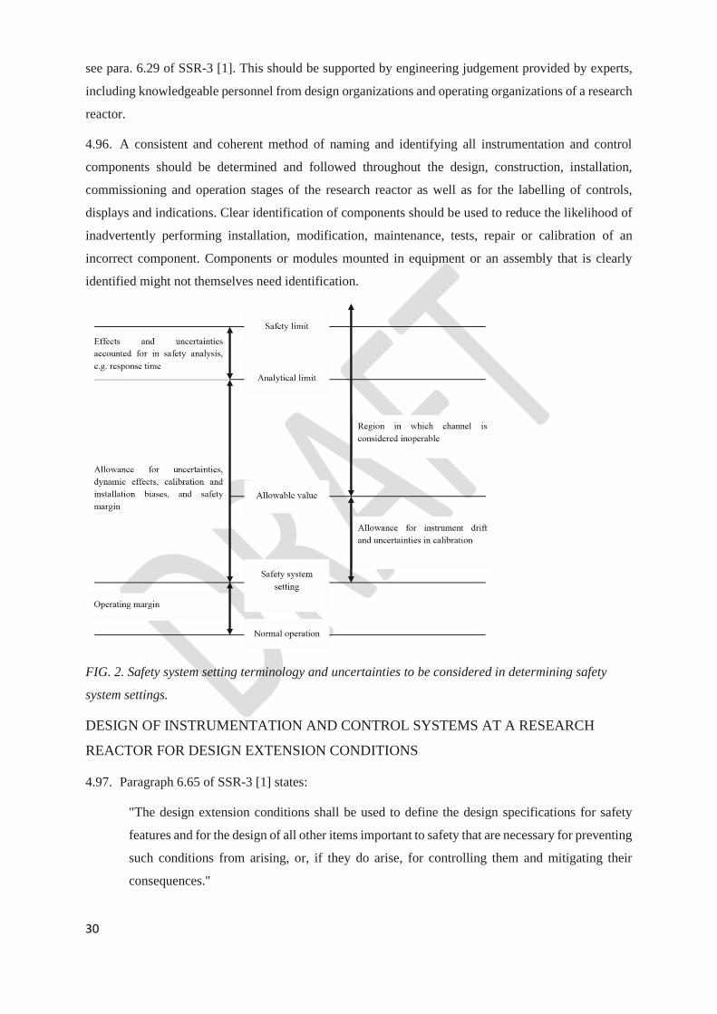
30
see para. 6.29 of SSR-3 [1]. This should be supported by engineering judgement provided by experts,
including knowledgeable personnel from design organizations and operating organizations of a research
reactor.
4.96. A consistent and coherent method of naming and identifying all instrumentation and control
components should be determined and followed throughout the design, construction, installation,
commissioning and operation stages of the research reactor as well as for the labelling of controls,
displays and indications. Clear identification of components should be used to reduce the likelihood of
inadvertently performing installation, modification, maintenance, tests, repair or calibration of an
incorrect component. Components or modules mounted in equipment or an assembly that is clearly
identified might not themselves need identification.
FIG. 2. Safety system setting terminology and uncertainties to be considered in determining safety
system settings.
DESIGN OF INSTRUMENTATION AND CONTROL SYSTEMS AT A RESEARCH
REACTOR FOR DESIGN EXTENSION CONDITIONS
4.97. Paragraph 6.65 of SSR-3 [1] states:
"The design extension conditions shall be used to define the design specifications for safety
features and for the design of all other items important to safety that are necessary for preventing
such conditions from arising, or, if they do arise, for controlling them and mitigating their
consequences."
31
4.98. The instrumentation and control systems and equipment provided as additional safety features for
design extension conditions should meet the design requirements for reliability, testability,
maintainability, inspectability, ageing management and (to the extent practicable) equipment
qualification. Such systems are considered to be items important to safety.
5. SYSTEM SPECIFIC DESIGN GUIDELINES FOR
INSTRUMENTATION AND CONTROL SYSTEMS FOR A RESEARCH
REACTOR
SENSING DEVICES FOR INSTRUMENTATION AND CONTROL SYSTEMS AT A
RESEARCH REACTOR
5.1. Measurements of variables for a research reactor should be consistent with the requirements of
the design basis. These measurements include both detection of the present value of a variable within a
range, and detection of a discrete state such as is detected by limit switches or on/off switches (e.g.
temperature, pressure, flow or level limit switches, switches for availability of the main supply or for
operation of the control system, interlock on/off switches).
5.2. The measurements of variables may be made directly or indirectly, such as calculation of the
value by performing multiple measurements, or by measuring other data having a known relationship to
the desired variable. To the extent practicable, the reactor conditions should be monitored by direct
measurements rather than being inferred from indirect measurements.
5.3. The sensor for each monitored variable and its range should be selected on the basis of the
accuracy, response time and range needed to monitor the variable in normal operation and in accident
conditions.
5.4. The vulnerability of sensing devices to common cause failure should be identified (e.g. saturation
of radiation monitors), as they have the potential to deny reactor operators the information and
parameters necessary to control and mitigate accident conditions.
5.5. If more than one sensor is necessary to cover the entire range of values for the reactor parameter
being monitored, a reasonable amount of overlap from one sensor to another should be provided.
Examples include source range, intermediate range and power range of neutron flux monitors.
5.6. If the monitored variables have a spatial dependence (i.e. if the measured value of a parameter
depends upon the location of the sensor), the minimum number and locations of sensors, such as flow
measurement elements, should be identified in the design and justified. The final locations also need to
be tested to verify the design assumptions and to determine whether associated set points, limiting
conditions and allowable values should be reassessed.
32
REACTOR PROTECTION SYSTEM
5.7. Requirement 50 of SSR-3 [1] states that: “A protection system shall be provided for a research
reactor to initiate automatic actions to actuate the safety systems necessary for achieving and
maintaining a safe state.” The design of this system is required include provisions for achieving and
maintaining a safe state even if the primary reactor protection system is subjected to a credible common
cause failure (e.g. hardware failure, failure due to human factors): see para. 6.177 of SSR-3 [1].
5.8. Where applicable, the reactor protection system should comply with the recommendations
provided in Section 4 of this Safety Guide for the design of instrumentation and control systems.
5.9. The reactor protection system should, at a minimum, include a function to initiate shutdown of
the reactor. For subcritical assemblies, the shutdown may be achieved by withdrawing the neutron
source. The reactor protection system may also provide other safety functions such as initiation of
emergency core cooling and confinement (the features of the reactor protection system thereby acting
as extended engineered safety features of the instrumentation and control system).
5.10. The reactor protection system is required to be capable of automatic response, without the need
for manual action within a short period of time, for the full range of postulated initiating events: see
paras 6.173 and 6.147 of SSR-3 [1].
5.11. As part of defence in depth and to cope with a potential common mode failure of the primary
reactor protection system, the need for a second reactor protection system with all or some of the
functions of the primary reactor protection system should be considered. Where two reactor protection
systems are provided, these two systems should be independent and diverse from one another.
5.12. The reactor protection system is required to be latched so that once an action is initiated it will
continue until its completion even if the initiating state is terminated: see para. 6.174 of SSR03 [1].
Latching of actions initiated by the protection system is normally implemented at the level of actuation
signals to reactor equipment and such actions should not reduce the reliability of the system below an
acceptable level.
5.13. In some cases, manual actions to initiate a protective action may be sufficient provided that the
diagnosis is simple, and the action is clearly defined, for example as follows:
(a) The reactor operator has sufficient and clearly presented information to make valid judgements on
the need to initiate the necessary safety actions.
(b) The reactor operator is allowed sufficient time to evaluate the status of the research reactor and to
complete the necessary actions.
(c) The reactor operator is provided with sufficient means of control of the reactor to perform the
necessary actions.
33
5.14. In addition to the automatic actions, means should be provided to manually initiate a reactor trip
and any other safety actions of the reactor protection system. Such manual actions should act directly
on the final actuation devices (e.g. reactor trip breakers) rather than being an input to the reactor
protection system logic.
5.15. System functions that inhibit the tripping of the reactor protection system, including the means
for activating and deactivating these functions, should be part of the reactor protection system.
Sometimes, it is necessary to inhibit the actions of the reactor protection system to enable changes in
reactor conditions. For example, the trips that limit reactor power during startup have to be inhibited at
some point to enable power increase. Another example would be the necessity to inhibit certain actions
in the case of pulsed operation of a research reactor. In this Safety Guide, such inhibit functions of the
reactor protection system are called operational interlocks and are classified as components and/or
functions of safety systems. The reactor protection system should prevent the enabling of an operational
interlock when the applicable enabling conditions are not met. If actions are inhibited and conditions
change so that this is no longer permissible, the reactor protection system should automatically disable
the operational interlock, or initiate appropriate protective actions. See also para. 6.175 of SSR-3 [1].
5.16. Where temporary connections of equipment are needed for periodic testing or calibration of the
reactor protective system, the operator should be alerted by alarms and/or warning lights of the presence
of the temporary connection and use of such equipment should be subject to appropriate interlocks or
administrative controls to ensure it is removed after use.
5.17. The design should ensure that safety system settings can be established with a margin between
the initiation point and the safety limits where the action initiated by the reactor protection system will
be able to control the process before the safety limit is reached. In addition, the following should be
taken into account in selecting such margins:
(a) Inaccuracy of instrumentation;
(b) Uncertainty in calibration;
(c) Instrument drift;
(d) Instrument and system response time.
5.18. If a computer based system is intended to be used in a reactor protection system, the life cycle of
the system is required to be systematically documented (see para. 6.180(b) of SSR-3 [1]) and
independent verification and validation processes should be applied.
5.19. Where a computer based system is intended for use in a reactor protection system, diverse means
of ensuring fulfilment of the protective actions should be considered. The diversity may be provided in
the following ways:
34
(a) Within the reactor protection system itself, or by a separate and independent system, provided that
the design bases are met;
(b) By a diverse system using distinct technology, which may be hard wired or computer based as long
as adequate diversity can be justified.
5.20. Paragraph 6.180(c) of SSR-3 [1] states:
“In order to confirm the reliability of the computer based systems, a systematic, fully documented
and reviewed assessment shall be undertaken by expert personnel who are independent of the
designers and the suppliers.”
5.21. For computer based reactor protection systems and components, the design is required to include
computer security features: see para. 6.180(d) of SSR-3 [1]. See also paras 4.39–4.51 of this Safety
Guide.
OTHER INSTRUMENTATION AND CONTROL SYSTEMS IMPORTANT TO SAFETY
OF A RESEARCH REACTOR
5.22. The reactor operator should be provided with sufficient instrumentation for monitoring the
operation of the reactor systems during normal operation (including shutdown, refuelling and
maintenance) and accident conditions, including the recording of all parameters important to safety.
5.23. The need for suitable startup neutron sources and dedicated startup instrumentation should be
taken into account in the design.
5.24. The operating organization should establish a set of design requirements and limitations on the
normal operation of the instrumentation and control systems necessary for the safe operation of the
research reactor. These design requirements and limitations should address the following:
(a) The information necessary to establish the safety limits and safety system settings;
(b) Control system constraints and procedural constraints on process variables and other important
parameters;
(c) Maintenance, testing and inspection of the research reactor to ensure that systems, structures and
components function as intended;
(d) Clearly defined operating configurations, including operational restrictions in the event of safety
system outages;
(e) Considerations for research related tasks.
These design requirements and limitations are the bases for establishing the operational limits and
conditions under which the research reactor is authorized to operate.

35
DESIGN OF RESEARCH REACTOR CONTROL ROOMS
5.25. In the main control room of a research reactor, measures are required to be implemented to protect
the occupants against hazardous conditions: see para. 6.185 of SSR-3 [1]. Similar provisions should be
made for a supplementary control room (see Requirement 54 of SSR-3 [1]) and other areas where
operating personnel are expected to monitor and control the research reactor systems. In all these
locations, the aim should be to ensure satisfactory conditions in the working environment.
5.26. Ergonomic factors and human factors are required to be considered in the design of control rooms:
see para. 6.104 of SSR-3 [1]. The results of task analysis should also be considered in the design of
control rooms.
5.27. To meet Requirement 39 of SSR-3 [1], the design of control rooms should include adequate
provisions for preventing unauthorized access and use.
5.28. The main control room is required to be designed and constructed to resist internal and external
hazards that might challenge its continued operation, in particular fires: see paras 6.185 and 6.186 of
SSR-3 [1]. At least one control room (main, supplementary or emergency) should be designed and
constructed to resist design basis earthquakes.
Main control room at a research reactor
5.29. The principal location for safety actions and safety related control actions is the main control
room. Requirement 53 of SSR-3 [1] states:
“A control room shall be provided at a research reactor facility. from which the reactor facility
can be safely operated in all its operational states and from which measures can be taken to
maintain the research reactor in a safe state or to bring it back into a safe state after anticipated
operational occurrences and accident conditions.”
Supplementary control room at a research reactor
5.30. A remote capability for reactor shutdown should be provided if the safety analysis identifies
events that could inhibit the reactor operator’s ability to shut down the reactor and to maintain it in a
safe condition from the main control room. A supplementary control room or an emergency control
console should be provided if reactor operators need to perform safety actions and the safety analysis
identifies events where the main control room could be unavailable or operations from the main control
room could be inhibited. Events that could inhibit the reactor operator’s ability to shut down the reactor
from the control room include, for example, a fire in the control room or a fire in a location that affects
connections between the control room and devices elsewhere in the research reactor.
5.31. The instrumentation and control systems of the supplementary control room are required to be
appropriately independent of the main control room (see Requirement 54 of SSR-3 [1]) to avoid
common cause failures diminishing the operability of the systems of the supplementary control room.
36
For example, the design of control system networking should ensure that there is an extremely low
likelihood of being unable to use the system from either of the two control rooms. Another example is
the separation of electrical power supplies for the control rooms.
5.32. A suitable provision outside the main control room for transferring priority control of the reactor
to a new location and for isolating the equipment in the main control room if it is abandoned should be
considered.
CONTROL SYSTEMS FOR IRRADIATION FACILITIES AND EXPERIMENTAL
DEVICES AT A RESEARCH REACTOR
5.33. In many research reactors, there are special control consoles for irradiation facilities and
experimental devices, which may be located in the main control room and/or in other rooms. The
operator of experimental devices should have communications links with the reactor operator to share
information on experiments and on the reactor status and to make each other aware of expected actions
(e.g. situations that necessitate the shutdown of the reactor).
5.34. The control consoles for irradiation facilities and experimental devices should be devoted
exclusively to the irradiation facilities and experimental devices if the safety analysis identifies events
that show an independent instrumentation and control system is necessary for irradiation facilities to
ensure a functional separation from other activities at the research reactor.
5.35. Parameters important to the operation of the reactor should be covered by the alarm system.
Alarms of experimental devices, with no reactor safety implications, should be presented with a
functional separation from the reactor alarms.
VOICE COMMUNICATION SYSTEM AT A RESEARCH REACTOR
5.36. Communication systems are required to be provided between the main control room and the
supplementary control room (if applicable) and the emergency centre: see paras 6.185 and 6.91 of SSR-
3 [1]. Secure means of communication should also be provided with other locations within the facility,
including with the operators of experimental devices and associated facilities, and with off-site response
organizations.
5.37. Both the main control room and the supplementary control room should have at least two diverse
communications links with the following:
(a) On-site locations where communications are needed in anticipated operational occurrences and
accident conditions;
(b) Off-site emergency response organizations;
(c) Other facilities that might be affected by the operation of the research reactor.
These communications links should be routed so that they will not all be affected by loss of the primary
communications links, whatever the cause of this loss (including external events), and they should be
37
capable of operating independently of both the research reactor power supply and the off-site power
supply.
5.38. Paragraph 6.189 of SSR-3 [1] requires the provision of relevant information and means of
communication from the control room(s) to the relevant emergency response facilities. The emergency
response facilities are also required to be provided with environmental monitoring information from
sources outside the research reactor. The information and communication links are required to be
designed for operation during accident conditions.
FIRE DETECTION SYSTEMS AND FIRE EXTINGUISHING SYSTEMS AT A
RESEARCH REACTOR
5.39. Requirement 61 of SSR-3 [1] states:
“Fire protection systems for a research reactor facility, including fire detection systems and fire
extinguishing systems … shall be provided throughout the research reactor facility, with due
account taken of the results of the fire hazard analysis.”
The nature of the fire alarm system, its layout, the necessary response time and the characteristics of its
detectors should be determined on the basis of the fire hazard analysis. The fire detection system should
provide a warning by means of audible and visual fire alarms in the control room of the specific location
of the fire.
5.40. Local audible and visual fire alarms, as appropriate, should also be provided in areas of the facility
that are usually occupied. Fire alarms should be distinctive to avoid confusion with any other alarms at
the facility.
5.41. The fire detection and alarm system is required to be operational at all times (see para. 6.207 of
SSR-3 [1]) and should be provided with non-interruptible emergency power supplies, including fire
resistant cables where necessary.
5.42. Fire detectors should be located so that the flow of air due to ventilation or pressure differences
that are necessary for contamination control will not cause smoke or heat energy to flow away from the
detectors and thus unduly delay actuation of the detector alarm.
5.43. If the environment does not allow detectors to be placed in the area to be protected (e.g. because
of increased radiation levels or high temperatures), alternative methods should be considered, such as
the sampling of the gaseous atmosphere by remote detectors with automatic operation.
5.44. When items such as fire pumps, water spray systems, ventilation equipment, fire dampers and the
corresponding power supplies are controlled or used by fire detection systems, and where spurious
operation would be detrimental to the research reactor and site personnel, operation should be controlled
by two diverse means of fire detection operating in series. The design should allow the operation of the
system to be stopped if the actuation is confirmed to be spurious. The potential effects on the research
38
reactor of the spurious operation of the system should also be considered, for example gas suppression
systems may be a good alternative to water sprinkler systems for rooms containing power systems and
instrumentation and control systems.
5.45. The following measures should be implemented for the wiring of fire detection systems, alarm
systems and actuation systems:
(a) The wiring should be protected from the effects of fire by a suitable choice of cable type, by proper
routing or by other means.
(b) The wiring should be protected from mechanical damage;
(c) The wiring should be continuously monitored for integrity and functionality.
5.48. The fire detection system and fire extinguishing systems should be periodically tested.
5.49. National requirements for fire protection should also be used as inputs to the design of fire
detection systems and fire extinguishing systems
POWER SUPPLIES OF INSTRUMENTATION AND CONTROL SYSTEMS AT A
RESEARCH REACTOR
5.46. The power supplies for instrumentation and control systems (see Requirement 56 of SSR-3 [1])
should be classified and qualified, and include provisions for reliability, isolation, testability,
maintainability and indication of removal from service that are consistent with the design basis of the
instrumentation and control systems that they serve. In addition, failure modes for these power supplies
should be considered.
5.47. Instrumentation and control systems that need to be available for use at all times, in operational
states and/or in accident conditions, are required to be connected to uninterruptible power supplies: see
para. 6.191 of SSR-3 [1]. Such power supplies should provide the instrumentation and control systems
with power within the tolerances specified by the design basis for the systems. These tolerances should
be specified for the instrumentation and control systems to ensure that the systems can withstand failures
in the normal power supply as well as a facility blackout caused by an external event.
5.48. Power supplies can provide a transmission path for electromagnetic interference that might
originate outside the instrumentation and control systems or might arise from other instrumentation and
control systems that are connected directly or indirectly to the same power supply. Such origins of
interference include electrical fault clearance associated with other equipment on the same supply. These
interferences should be analysed and should be avoided to the extent possible.
39
6. OPERATION OF INSTRUMENTATION AND CONTROL SYSTEMS
DURING THE OPERATION OF AT A RESEARCH REACTOR
INSTRUMENTATION AND CONTROL SYSTEMS AND OPERATIONAL LIMITS AND
CONDITIONS AT A RESEARCH REACTOR
6.1. Requirement 71 of SSR-3 [1] states that:
“The operating organization for a research reactor facility shall ensure that the research
reactor is operated in accordance with the operational limits and conditions.”
6.2. The instrumentation and control systems of the research reactor help to ensure that the reactor’s
operating parameters are kept within the operational limits and conditions. Recommendations on
operational limits and conditions for research reactors are provided in DS509D [5].
Safety limits for a research reactor
6.3. The instrumentation and control systems at a research reactor should function to prevent safety
limits from being exceeded in operational states, in design basis accidents and in design extension
conditions.
Safety system settings for a research reactor
6.4. Each parameter for which an analytical limit (see para. 4.92) is required to actuate a safety system,
and any other important safety related parameters, should be monitored by an instrumentation and
control system. Where appropriate, the system should provide a signal that can be utilized to
automatically prevent that parameter from exceeding the set limit.
Limiting conditions for safe operation for a research reactor
6.5. Acceptable margins between normal operating values and the safety system settings should be
applied in the instrumentation and control systems to ensure safe operation of the reactor, while avoiding
the frequent actuation of safety systems. Acceptable margins should allow for instrument accuracy,
system response time, expected drift and allowable margin of error in measured signals and for all
expected variations in normal operation.
CONTROL OF ACCESS TO INSTRUMENTATION AND CONTROL SYSTEMS
IMPORTANT TO SAFETY AT A RESEARCH REACTOR
6.6. Requirement 39 of SSR-3 [1] states that:
“Unauthorized access to, or interference with, items important to safety at a research reactor
facility, including computer hardware and software, shall be prevented.”

40
All reasonable precautions should be taken to prevent persons from performing unauthorized actions
that could jeopardize safety when accessing instrumentation and control systems or performing tasks on
instrumentation and control systems.
6.7. Access to instrumentation and control systems classified as important to safety should be
controlled. Access control methods should include physical restrictions or barriers, special embedded
devices and restrictions on access to functions important to safety by means of hardware or software
access keys, access alarms and administrative controls.
6.8. Wherever safety system settings are configured, only authorized personnel should be allowed to
change these settings, and these settings should be checked for their integrity. Access to the safety
system settings and calibration adjustments should be restricted by physical and administrative means.
6.9. The protection of computer based components of instrumentation and control systems needs to
be addressed in appropriate security procedures that take into account national requirements, Guidance
on computer security is provided in Refs [15–17].
6.10. Secure storage arrangements and procedural controls should be used to ensure that only
authorized software versions are uploaded into instrumentation and control systems and equipment at
the research reactor. Records of software versions should be maintained within the management system
for the research reactor. The correct performance of the computer based system should be demonstrated
before it is returned to service.
6.11. Electronic access to software and data of computer based systems important to safety via network
connections from outside the reactor should be prohibited.
6.12. Access control methods should be used to ensure that users can only access data and commands
for which they have been authorized.
6.13. Suitable measures should be implemented to prevent unauthorized access to software, the use or
corruption of software or data, the introduction of malicious code, unauthorized connections to external
networks or other computer based attacks.
MAINTENANCE, PERIODIC TESTING, AND INSPECTION OF INSTRUMENTATION
AND CONTROL SYSTEMS AT A RESEARCH REACTOR
6.14. Maintenance, periodic testing, and inspection is required to be conducted on instrumentation and
control systems important to safety to ensure that all their components function in accordance with the
design requirements and intent, in compliance with the operating limits and conditions: see para. 7.68
of SSR-3 [1]. The frequency of such activities is required to be consistent with the reliability
requirements for such systems or components: see para. 7.72 of SSR-3 [1]. Further recommendations
are provided in DS509B [3].

41
6.15. The instrumentation and control systems at a research reactor should facilitate periodic testing
and, where applicable, include on-line testing functions to reduce the number of insertions and
extractions of connectors, and thereby improving the system reliability.
PROVISIONS FOR REMOVAL FROM SERVICE OF INSTRUMENTATION AND
CONTROL SYSTEMS FOR TESTING OR MAINTENANCE
6.16. Removal from service of any single safety system, component or channel should not result in loss
of the required minimum redundancy unless the acceptably reliable operation of the system can be
adequately demonstrated.
6.17. If use of equipment for testing or maintenance can impair an instrumentation and control function,
the interfaces should be subject to hardware interlocking to ensure that interaction with the test or
maintenance system is not possible without deliberate manual intervention.
6.18. For safety systems, design features should ensure that during periodic tests of part of a safety
system, those parts remaining in service can continue to perform the required safety function(s). For
example, tripping the redundancy during the testing of a ‘two out of three’ logic leaves the system in a
‘one out of two’ logic arrangement. Administrative controls on the availability of safety systems should
keep them in operation within the design basis.
INSTRUMENTATION AND CONTROL SYSTEMS DURING EXTENDED SHUTDOWN
OF A RESEARCH REACTOR
6.19. The operating organization should assess and define the minimum instrumentation and control
systems important to safety that need to be kept operational during an extended shutdown.
7. HUMAN FACTORS ENGINEERING AND HUMAN–MACHINE
INTERFACES AT A RESEARCH REACTOR
7.1. An effective process for human factors engineering is required to be embedded into the overall
design process for every aspect of the design: see Requirement 35 of SSR-3 [1]. Appropriate design
standards and guidelines should be identified and should be used throughout the design process.
7.2. Verification and validation should be performed throughout the design process for
instrumentation and control systems for a research reactor to confirm that the design adequately
accommodates all necessary actions by operating personnel and all relevant administrative arrangements
of the operating organization. This could include task analysis and consideration of factors such as
timing and human cognition and perception, operator overload and available indications for the operator
response.
42
7.3. If a part of an instrumentation and control system is modernized, careful consideration should be
given to the design of the modernized part of the system and to its compatibility with and human
interaction with the existing systems.
CRITERIA FOR HUMAN FACTORS ENGINEERING AND DESIGN OF HUMAN–
MACHINE INTERFACES AT A RESEARCH REACTOR
7.4. The design of human–machine interfaces should take into account operating experience to retain
useful features and avoid problems with human factors engineering. Such design considerations should
be taken into account in the system architecture for new projects as well as for modification projects.
The design of human–machine interfaces should emphasize the importance of human factors and of
machine features and take both into account.
7.5. Instrumentation and control functions necessary to achieve the safety objectives for the research
reactor should be identified and the human resources and system resources necessary to fulfil these
functions should be allocated in accordance with a specified method and should be taken into account
in the system architecture at the design stage.
7.6. All human–machine interfaces should be designed in accordance with ergonomic criteria. The
operating organization should determine which information is most effectively displayed using
conventional displays (e.g. panel instruments, alarm annunciators) and which information is most
effectively displayed using video screens. In the design criteria for information displays and controls,
the different roles and authorized access levels of operating personnel such as reactor operators,
maintenance personnel, systems managers and personnel with responsibilities in an emergency should
be taken into account.
7.7. Design requirements for human–machine interfaces should be specified on the basis of all the
tasks to be supported by the interfaces, including during normal operation and during anticipated
operational occurrences and accident conditions. This should include tasks undertaken by reactor
operators, maintenance staff, experimenters and personnel with responsibilities in an emergency.
7.8. In accordance with Requirement 49 of SSR-3 [1], the instrumentation and control system is
required to provide the information necessary to detect changes in the status of systems and to make
decisions for accident management. The human–machine interfaces are required to include the
instrumentation and control systems necessary to assess the general state of the research reactor in any
condition, to confirm that automatic safety actions are implemented as intended and to determine both
the need for and the time for manual safety actions: see para. 6.105 of SSR-3 [1].
7.9. During operation of the research reactor, the reactor operator should be provided with suitable
warnings or alarms when the facility is approaching a state in which operational interlocks should be
enabled or should be disabled.
43
7.10. The reactor operator should be provided with sufficient indicators and recording instrumentation
to be able to monitor relevant reactor parameters in, and following, anticipated operational occurrences
and accident conditions.
7.11. Audible and visual alarm systems should be used to provide an early indication of changes in the
operating conditions of the reactor if these changes in the operating conditions could affect its safety.
7.12. Careful attention should be paid in the design of human–machine interfaces to ensure that reactor
operators would not be overwhelmed by large amounts of data that could be difficult to assimilate owing
to the inherent limitations on human perception, cognition and memory. This is particularly important
for the design of alarms.
7.13. In the design of the instrumentation and control system, due account should be taken of the time
periods necessary for reactor operators to perform their expected tasks.
7.14. The instrumentation and control system should protect against human errors by implementing
range limits, interlocks or trips to protect the research reactor from unsafe operation.
7.15. Where a safety function is performed automatically, the instrumentation and control system
should provide reactor operators with the necessary information to monitor the performance of the
function. The information should be provided at a rate and to a level of detail that reactor operators can
monitor effectively.
7.16. The instrumentation and control system should alert the reactor operator of a failure of an
automatic control system.
7.17. The presentation of information should be harmonized to facilitate understanding of the status of
the research reactor and of the activities necessary to ensure safety.
7.18. The operation and appearance of the human–machine interfaces in different locations within the
research reactor should be consistent, should reflect a high degree of standardization and should be
consistent with operating procedures and the training provided to operating personnel.
7.19. The human–machine interfaces should include the capability to display recorded information
where such information will help reactor operators identify patterns and trends, to understand the past
or present state of the system, or to predict its future progression. The design of display screens should
ensure that a frozen display is easily identified.
HUMAN FACTORS ENGINEERING FOR RESEARCH REACTOR CONTROL ROOMS
7.20. Ergonomic factors are required be taken into account in the design of the research reactor control
room: see para. 6.104 of SSR-3 [1]. Aspects of human factors engineering such as workload, possibility
of human error, operator response time and minimization of the physical and mental effort of reactor
operators should be taken into account in order to facilitate the execution of the necessary operating
procedures to ensure safety in all operational states and accident conditions.
44
7.21. Acceptable working environments in the control room — in terms of radiation levels, lighting,
temperature, humidity, noise, dust and vibration — should be ensured for normal operation, anticipated
operational occurrences and accident conditions. The design of the main control room is required to take
into account conditions resulting from internal hazards (e.g. fire or smoke, toxic substances in the
atmosphere) and external hazards (e.g. earthquakes, flooding, extreme meteorological conditions,
hazards due to human error): see paras 6.185 and 6.186 of SSR-3 [1]. Similar provisions should be made
for the supplementary control room, if applicable.
7.22. The layout of instrumentation and the means of presenting information to operating personnel,
with both an adequate overall summary of the status and performance of the research reactor and, where
necessary, detailed information on the status and performance of particular systems or equipment,
should be considered in the design.
7.23. The information displayed in the main control room should allow reactor operators to achieve the
following:
(a) To take specific manually controlled actions for which no automatic control is provided;
(b) To confirm the availability of safety functions and the performance of automatic safety actions;
(c) To determine the potential for the breach of a fission product barrier or to detect such a breach;
(d) To confirm the performance of safety systems, auxiliary supporting features and other systems
necessary for the mitigation of accident conditions or for achieving and maintaining a safe state;
(e) To determine the magnitude of any radioactive releases and to continually assess such releases.
7.24. The parameters displayed in the supplementary control room may differ from those displayed in
the main control room if the supplementary control room does not need to be used to respond to the
same range of anticipated operational occurrences and accident conditions as the main control room.
For the supplementary control room, sufficient instrumentation and control equipment is required to be
available so that the research reactor can be placed and maintained in a safe state, residual heat can be
removed, confinement functions can be performed and the essential facility parameters can be monitored
in the event of a loss of ability to perform essential safety functions from the main control room: see
para. 6.188 of SSR-3 [1]. The instrumentation and control equipment in the supplementary control room
should be physically and electrically separate from the equipment in the main control room.
8. COMPUTER BASED SYSTEMS AND SOFTWARE AT A
RESEARCH REACTOR
8.1. Requirement 52 of SSR-3 [1] states:
45
“If a system important to safety at a research reactor is dependent upon computer based
equipment, appropriate standards and practices for the development and testing of computer
hardware and software shall be established and implemented throughout the lifetime of the
system, and in particular throughout the software development cycle.”
8.2. Computer based systems are of increasing importance to safety in research reactors as their use is
increasing in both new and older facilities. Such systems are used both in safety related applications,
such as process control systems and monitoring systems, and in safety applications, such as the reactor
protection system.
8.3. Paragraph 6.184(c) and (d) of SSR-3 [1] states:
“For computer based equipment in safety systems and systems important to safety…An
assessment of the equipment shall be undertaken by experts who are independent of the design
team and the supplier team to provide assurance of its high reliability. When the necessary high
reliability of the equipment cannot be demonstrated with a high level of confidence, diverse means
of ensuring fulfilment of the safety functions shall be provided”.
The reliability of computer based systems should be evaluated in accordance with a systematic, fully
documented and reviewed engineering process. This process should include the evaluation of new
software and involve the use of operating experience from the use of pre-existing software.
8.4. Software faults are systematic in nature and not random, and therefore potential common cause
failures are required to be considered: see para. 6.184(e) of SSR-3 [1]. In particular, computer based
safety systems employing redundant hardware subsystems using identical copies of the software should
be systematically considered.
8.5. Depending on the complexity of experimental devices in the research reactor, consideration
should be given to having separate computer based instrumentation and control systems for the reactor
and for experiments. In such cases, each system could be provided with its own set of design
requirements and objectives.
8.6. Obsolescence management should be taken into account in the design and operation of computer
based systems to plan for and manage reductions in service life, diminishing manufacturing sources and
material shortages.
DESIGN CONSIDERATIONS FOR COMPUTER BASED SYSTEMS AND SOFTWARE
AT A RESEARCH REACTOR
8.7. For computer based safety systems, complexity should be avoided, both in the functionality of
the system and in its implementation, by the use of a structured design that follows a formal software
development life cycle. Concepts such as ‘top-down’ decomposition, levels of abstraction and modular
structure are important for coping with complexity. The logic behind the system modularization and the

46
definition of interfaces should be made as simple as possible. A ‘top-down’ design process (i.e. breaking
the system down to gain insight into its subsystems) for the system and its associated software should
be used to facilitate the assessment of whether design objectives are being achieved.
8.8. With regard to safety systems at a research reactor, the functional requirements be fulfilled by a
computer system should all be essential to the fulfilment of safety functions. Functions not essential to
safety should be isolated to avoid any impact on safety functions.
8.9. When a computer system incorporates two or more components in different safety classes, the
computer system should meet the requirements of the higher safety class.
8.10. The use of diverse functions and system components at different levels of the design of computer
based systems should be considered.
8.11. System fail-safe features, self-supervision and fault tolerant mechanisms should be incorporated
into the software, but only to the extent that the additional complexity is justified by design basis
functional requirements and performance requirements. Fault detection and self-supervision features
should not adversely affect the ability of a computer system to perform its safety function or cause
spurious actions.
8.12. Paragraph 6.184(f) of SSR-3 [1] states:
“For computer based equipment in safety systems and systems important to safety … Protection
shall be provided against accidental disruption of, or deliberate interference with, system
operation (computer based systems and communication and network systems important to safety,
including the reactor protection system, are to be adequately protected against cyber-attacks, up
to and including the design basis threat.”
It should be demonstrated that measures have been taken to protect a computer based system throughout
its entire life cycle against physical attack, unauthorized access, fraud, computer viruses and other such
threats. Safety systems should not be connected to external networks. The connections for external
storage devices should be locked to prevent unauthorized use.
8.13. A computer based system at a research reactor should be designed for maintainability to facilitate
the detection, locating and diagnosis of potential or actual failures so that the system can be repaired or
replaced efficiently. Software that has a modular structure may be easier to repair, review and analyse,
since the design may be easier to understand. Maintainability of software also includes the concept of
making changes to the functionality. The design of a computer based system should allow, as far as
practicable, that changes are confined to a small part of the software.
8.14. Computer based systems that perform safety functions should have deterministic behaviour with
regard to functions and timing, meaning that any given input sequence that is within the specification of
the system will always produce the same outputs within the same response time.
47
8.15. Sample rates and processing speed should be consistent with requirements for accuracy and
timing.
8.16. Data communications channels important to safety should satisfy the recommendations for
independence in para. 4.21. The design should ensure that errors and failures of transmission equipment
and data communications equipment are detected and that suitable alarms are provided for operating
personnel and that records are made for the analysis of performance.
8.17. The communications technology for a research reactor should be chosen and configured to ensure
that it is capable of a timely response under all possible conditions of data loading.
8.18. Appropriate consideration should be given to the use of redundancy in data communications.
8.19. The topology and network interface of the data communications network should be designed and
implemented, from both an electrical and a communication protocol perspective, to avoid common cause
failures of independent systems or subsystems.
8.20. Data flow from lower classified safety systems to higher classified safety systems should be
avoided unless a decoupling device is installed, and a decoupling protocol is used, to allow such
communication only on demand.
8.21. The selection of pre-developed items to be included in computer based systems at a research
reactor should follow a defined and documented process to guarantee their suitability.
8.22. Software tools can be used to support the life cycle of instrumentation and control systems. These
tools should be verified and assessed in accordance with the reliability requirements, the type of tool,
and with the potential for the software tool to introduce errors or to fail in detecting existing errors.
PROJECT PLANNING FOR COMPUTER BASED SYSTEMS AND SOFTWARE AT A
RESEARCH REACTOR
8.23. The project development process for computer based systems and software at a research reactor
should be carefully planned and clear evidence should be provided that the process has been followed
to facilitate the independent assessment of systems important to safety. The development plan should
identify and define the process that will be used on the particular project. Other aspects of the project
that should be considered and planned are quality management, verification and validation,
configuration management, installation and commissioning.
8.24. All phases of the development process for computer based systems and software at a research
reactor should be identified. The design activity of preceding phases should provide the inputs for the
next phase. Verification should be performed across each phase of the development process.
8.25. The methods to be used in the development process should be identified. The selection of methods
should be in accordance with a quality management programme in which processes and procedures are

48
established. The quality management programme should be prepared and implemented before the
project begins. A software quality management plan should be available at the start of the project.
Verification and validation of computer based systems and software at a research reactor
8.26. Paragraph 6.184(g) of SSR-3 [1] states:
“For computer based equipment in safety systems and systems important to safety … Appropriate
verification and validation and testing of the software systems shall be performed.”
Verification and validation activities should be performed to demonstrate that the computer system
achieves its overall safety objectives and functional requirements. Specific techniques and validation
procedures should be included in the verification and validation plan.
8.27. Verification and validation planning should include the listing and collection of applicable codes
and standards, procedures and conventions that guide the verification process.
8.28. The teams performing verification and validation should be independent of the development team.
Independence is usually ensured by having a different line management for the verification and
validation teams and for the development teams. Personnel performing verification and validation
should not have been involved in the design of the same project. A different organization could be used
to complete the verification and validation activities.
8.29. The verification and validation plan should include a mechanism for recording all instances of
non-compliance found during the analysis and ensuring that they are properly resolved by means of an
approved change control process.
Configuration management of computer based systems and software at a research reactor
8.30. All items related to software development, such as compilers, development tools, configuration
files and operating systems, should be subject to configuration management. All identifiable items, such
as documents, components of the software or data structures, should be given a unique identification,
including the version number. These items should include both developed items and existing items that
are being reused or reapplied.
8.31. A procedure for change control should be established. This should provide for the keeping of
records of any problems identified during the development process, or during the operation of the
research reactor, that necessitated changes to computer based systems or software. It should also provide
for documenting problems and their analysis, items that were affected, changes that were made to solve
the problem, and which versions (such as version numbers of software or components of software) and
which baseline database of systems and components of the instrumentation and control systems were
produced as a result. The change control procedure should specify responsibilities for approving
changes.
49
Installation and commissioning of computer based systems and software at a research reactor
8.32. The installation and commissioning plan for computer based systems and software at a research
reactor should cover the following:
(a) The sequence of steps for proper integration of the system into the research reactor and the
corresponding facility states necessary for the safe introduction of the new or changed system;
(b) The required interactions with the regulatory body, including approvals, hold points and reports,
that are necessary before the system can be put into operation;
(c) The commissioning test cases and sequence and the corresponding facility states necessary to
confirm proper functioning of the system in the environmental conditions at the research reactor;
(d) A description of the records and reports that will be necessary to describe the results of
commissioning.
SPECIFICATION OF COMPUTER BASED SYSTEM REQUIREMENTS AT A
RESEARCH REACTOR
8.33. The specifications for a computer system for a research reactor should include, at a minimum, the
necessary functional properties and non-functional properties of the computer system. Safety analyses
(e.g. facility safety analyses, transient analyses, accident analyses, based on postulated initiating events
and safety criteria) should be used in specifying the functional requirements. Other requirements not
directly associated with safety, such as for availability or security, should be included at this stage of the
design.
8.34. A safety analysis should be made for safety systems and safety related systems to determine the
functional requirements for these systems.
8.35. The specification of non-functional requirements should include the following:
(a) The relevant dependability attributes, such as reliability, availability and safety performance of the
system;
(b) The security requirements for the computer based systems, including security procedures;
(c) Performance requirements (e.g. the response time of software modules for performing safety
functions);
(d) Environmental qualification requirements, such as for temperature and radiation;
(e) Whether and where physical separation is needed (e.g. between safety functions and control
functions);
(f) A confirmation that requirements not directly associated with safety (e.g. requirements for
availability or security) will not adversely affect the ability to perform a safety function.
50
An accurate and clear description of these requirements should be formulated before starting the next
stage of the project, and this description should be subject to independent review.
SOFTWARE REQUIREMENTS FOR A RESEARCH REACTOR
8.36. The specification of software requirements should define the function(s) of each individual
software item and how it will interact with other items of the system. Software requirements for a
research reactor should be complete, unambiguous, consistent, clear and understandable to their target
audience (e.g. domain experts, safety engineers, software designers), verifiable and traceable. The origin
of every software requirement should be sufficiently documented to facilitate verification, validation,
traceability to higher-level documents and to demonstrate that all software requirements have been
addressed.
8.37. The software requirements should include a description of the allocation of system requirements
to the software, with a consideration of potential failure conditions, functional requirements in each
mode of operation, performance criteria, timing and constraints, detection of failures, logging of events,
self-supervision, monitoring of safety and interfaces with nuclear security.
SOFTWARE DESIGN FOR A RESEARCH REACTOR
8.38. In the software of systems important to safety at a research reactor, unnecessary complexity
should be avoided at all levels of design. The simpler the design is, the easier it is to achieve and
demonstrate all other attributes. It also gives greater confidence that the software is fully understood.
8.39. To facilitate tracing of compliance of software requirements through the design, each design
element, such as a software module, a procedure, a subroutine or a file, should have a unique identifier.
8.40. The design of software for a research reactor should contain no contradictions and no ambiguities.
The description of the interfaces between modules should be complete. In addition to internal interfaces
between modules of the software, the design should explicitly specify the external interfaces of the
software, such as hardware interfaces and libraries. The design and its description should demonstrate
that each software design requirement has been met and should enable verification that the
implementation is correct with respect to the detailed design.
8.41. The documentation of software design should provide technical information on the software
architecture and on the detailed design of all software modules and their concurrence, with
synchronization to prevent unpredictable results in terms of response time. Relevant constraints on
implementation should also be specified.
8.42. Each software module identified in the software architecture should be described in the detailed
design. Diagrams and flow charts can be used provided that the meaning of the elements of the diagrams
is well defined. Common techniques used for describing design include data flow diagrams, structure
diagrams or graphics.
51
8.43. Peer review should be conducted at the software design stage to avoid potential errors and to
improve software quality.
SOFTWARE IMPLEMENTATION FOR A RESEARCH REACTOR
8.44. The production of software code should be verifiable against the software design requirements.
The code should be readable, adequately commented and understandable. Validated software tools can
be used to facilitate the code verification process.
8.45. A formal system for requesting changes and controlling modifications to software for a research
reactor should be used during the implementation phase to deal with omissions and inconsistencies. Up
to date records of changes should be kept available for reviews and audits.
8.46. The code of each computer program should be kept simple and easy to understand, both in its
general structure and in its details. Data structures and their naming conventions should be used
uniformly throughout the whole computer based system.
VERIFICATION AND ANALYSIS OF SOFTWARE FOR A RESEARCH REACTOR
8.47. Techniques for verification and analysis should be used to provide assurance of software quality
and compliance with instrumentation and control system requirements.
8.48. A software verification plan should be produced that documents the following:
(a) The verification techniques to be used;
(b) Details of, or references to, the procedures to be used in applying each technique, including its
scope and depth;
(c) How non-functional requirements and constraints will be demonstrated to be met;
(d) The criteria for determining when sufficient verification has taken place, including targets for
completeness with respect to the outputs of the previous phase and for structural coverage of the
functional tests, and how these will be demonstrated;
(e) The means by which results will be recorded;
(f) The means by which non-compliances and faults will be recorded and resolved;
(g) The team(s) performing the verification and their independence from the designers of the software
(see para. 8.50);
(h) The functionality of any software tool for verification, including expectations and limitations on
how it is to be used (e.g. domain, language, process);
(i) The rationale for each of the elements listed in items (a)–(h) above, and justification that the
verification will be sufficient for software in the system of the safety class to which it is applied.
8.49. A software test plan should be developed covering all testing to be done, including unit level tests,
integration tests, factory acceptance tests and installation tests.
52
8.50. Verification should be performed by teams, individuals or organizational groups that are
independent of the designers and developers.
8.51. The software code should be reviewed to check for security vulnerabilities using automated
software tools and complemented by manual review of the critical sections of the code (e.g. input/output
handling, exception handling).
8.52. All outputs of the instrumentation and control system should be monitored during the verification
of the software code and any deviation from the expected results should be investigated and documented.
8.53. Any shortfall in the verification results against the verification plan (e.g. in terms of the test
coverage achieved) should be documented and resolved or justified.
8.54. Any errors detected should be analysed for cause and should be corrected by means of agreed
modification procedures and regression tested, as appropriate, to ensure that previously developed and
tested software still performs correctly after a change. The error analysis should include an evaluation
of applicability to other parts of the instrumentation and control systems.
8.55. Records of the number and types of anomalies should be maintained. These records should be
reviewed to determine whether or not any lessons could be learned and whether appropriate process
improvements should be made.
8.56. Techniques such as reviews, inspections or audits should be applied to the verification of all
phases in the life cycle of computer based systems and software. The method by which the results of the
reviews, inspections or audits are to be recorded should be stated in the verification plan together with
a justification of the method used.
8.57. Review of the documentation on software design and software implementation should be
performed. Software test cases should be designed on a functional basis only (i.e. without knowing the
structure of the software under test) to preserve the independence of the testing activity and to enable
analysis of the structural coverage of the tests performed after their design. The test case specifications
should be fully documented and reviewed.
8.58. Test plans should be designed to facilitate regression testing by ensuring that tests are repeatable
and involve minimal human intervention.
8.59. Any anomalies in the performance of testing should be reviewed and, if it is determined that there
is a need for a modification to the test procedure, an appropriate procedure for change control should be
applied.
8.60. Any anomaly in the software test performance should be documented in a report that includes the
nature of the problem, the identified corrective action, the retest arrangements and the completion of a
satisfactory retest. In addition, a cross-reference record of software corrections and software builds
should be maintained for configuration management of the installed software.
53
THIRD PARTY ASSESSMENT OF SOFTWARE FOR A RESEARCH REACTOR
8.61. A third party assessment of software for safety systems at a research reactor should be conducted
concurrently with the software development process.
8.62. The objective of such a third party assessment is to provide a view on the adequacy of the system
and its software that is independent of both the supplier of the system and/or software and the operating
organization. Such an assessment may be undertaken by the regulatory body or by a body acceptable to
the regulatory body.
8.63. It is important that proper arrangements are made with the software originator to permit third
party assessment.
8.64. The assessment should involve an examination of the following:
(a) The development process (e.g. through quality assurance audits and technical inspections,
including examination of life cycle documents, such as plans, software design requirements and
the full scope of test activities);
(b) The final software (e.g. through static analysis, inspection, audit and testing), including any
subsequent modifications.
COMPUTER SYSTEM INTEGRATION AT A RESEARCH REACTOR
8.65. The software version integrated into the computer system of a research reactor should be the latest
version to have been verified and validated.
8.66. The computer system integration phase should encompass at least three sequenced activities:
software tests; hardware testing and integration; and hardware–software integration. The hardware–
software integration should consist of three parts: loading of all software into the hardware system;
testing that the software–hardware interface requirements are satisfied; and testing that all the software
can operate in the integrated software–hardware environment.
8.67. During the verification of the computer system, evidence should be generated to demonstrate that
the system integration has been properly checked and verified. A traceability analysis should be
performed and documented as part of this verification to demonstrate that the system integration
requirements are complete with respect to the design specification for the computer system.
Integrated computer system tests at a research reactor
8.68. The integrated computer system tests should be performed before the system is transferred to the
research reactor and installed. The final integrated computer system test is often combined with the
factory acceptance test to form a single test activity.
8.69. In constructing test cases, special consideration should be given to the following:
54
(a) Coverage of all design requirements for the hardware and software (including robustness tests and
features);
(b) Coverage of the full ranges of values for input signals;
(c) Handling of exceptions (e.g. demonstration of acceptable behaviour when input failure occurs);
(d) Timing related requirements (e.g. response time, input signal scanning, synchronization);
(e) Accuracy;
(f) All interfaces (e.g. the hardware–software interface in system integration and external interfaces
during validation);
(g) Stress testing and load testing;
(h) Requirements for security (e.g. logging of user activities);
(i) All modes of operation of the computer system, including transition between modes and recovery
after failure of the power supply.
8.70. A traceability analysis should be performed to demonstrate that the validation process for testing
and evaluation is complete.
Validation and commissioning tests of computer based systems and software at a research reactor
8.71. Validation and commissioning tests should be performed to verify that the computer system has
been correctly connected at the research reactor and to confirm the correct functioning of the system.
8.72. The validation and commissioning tests should usually be combined with the site acceptance test,
which includes verification of the operation of the equipment.
8.73. Strict configuration control of the computer system (both hardware and software) should be
maintained during the commissioning programme. Any changes made should be subject to a formally
documented change process.
8.74. Sufficient documentation should be produced to demonstrate the adequacy of the commissioning
programme for the installed computer based system and software.
Operation, maintenance and modification of computer based systems and software at a research
reactor
8.75. The following activities should be considered with regard to the operation, maintenance and/or
modification of computer based systems and software at a research reactor:
(a) Periodic tests, performed to verify that the systems are not degrading;
(b) Regression testing because of modifications, performed to enhance or change the functionality or
to correct errors;
55
(c) Change of operating parameters;
(d) Diagnostic activities, for example the execution of special diagnostic programmes;
(e) Replacement of hardware components because of failures.
8.76. All software tools used in software development, testing, installation, integration, operation and
maintenance should be qualified.
8.77. The life cycle of the systems should include the processes for implementing modifications. This
life cycle should include the main phases of the development, including verification and validation.
These activities, together with an impact analysis and regression testing, will be necessary to ensure that
the modifications have been correctly implemented and no new errors have been introduced.
8.78. After failure of a hardware component, corrective actions should be limited to one-by-one
replacements of hardware components and to the reloading of the existing software modules. These
actions should not include any modification unless analysis of the failed components reveals a need for
modification.
9. CONFIGURATION MANAGEMENT OF INSTRUMENTATION
AND CONTROL SYSTEMS AT A RESEARCH REACTOR
9.1. A full set of documents reflecting the configuration and status of instrumentation and control
systems at the research reactor should be available prior to the commissioning of the facility. The
documentation should be kept up to date throughout the lifetime of the research reactor.
9.2. A baseline database of systems and components of the instrumentation and control systems should
be established and should include the following information:
(a) General information (e.g. system identification, serial number, manufacturer, supplier
support, location, safety class);
(b) System summary (e.g. functions, configuration, impacts of the system on safety, current
performance, loss of operational availability in the event of unavailability of the system,
interfaces, documentation);
(c) Physical characteristics (e.g. number of cabinets, detailed component inventory, operational
limits);
(d) Boundaries (e.g. environmental conditions, power supply, grounding, power supply margins
necessary in the cabinets and rooms, the amount of information exchanged with other systems);
(e) System constraints (e.g. licensing conditions, technical specifications, design constraints,
operating characteristics);
56
(f) Obsolescence issues (e.g. maintenance costs, replacement parts, performance degradation);
(g) Measures for improvements (e.g. functionality, configuration, performance, maintenance);
(h) Supporting references.
9.3. Reactor operators and maintenance personnel should collaborate in the improvement and the
updating of documentation for configuration management of instrumentation and control systems. The
documentation and database described in paras 9.1 and 9.2 should be considered to be sensitive
information and should be protected in accordance with national requirements for security of
information.
10. MODIFICATION AND MODERNIZATION OF
INSTRUMENTATION AND CONTROL SYSTEMS AT A RESEARCH
REACTOR
10.1. The main reasons to modernize instrumentation and control systems at a research reactor are
obsolescence of the existing systems (e.g. as a result of the unavailability of spare parts) or an increased
failure rate of the systems. These developments can lead to frequent reactor shutdowns and long repair
periods, resulting in increasing unavailability of the research reactor. Recommendations on ageing
management for research reactors are provided in SSG-10 (Rev. 1) [8].
10.2. Additional reasons for modernization are the technological progress in instrumentation and
control systems, which can provide greater reliability, improved human–system interfaces, and more
extensive and faster data collection and data processing. Other factors (e.g. new regulatory requirements)
may also influence the final decision for modernization of the instrumentation and control systems at a
research reactor.
10.3. Before modernizing an instrumentation and control system, information on current limitations
and future needs should be collected using experience from the existing system. This includes
information from past failures and incidents, which could be collected by event recording systems used
at the research reactor. Other weaknesses could be identified from the self-assessment of operational
performance, including analysis of even small deviations from normal operation. In addition, possible
future problems should be considered and the potential impact of these should be assessed.
10.4. The modification and modernization of instrumentation and control systems should be
performed in accordance with the recommendations provided in SSG-24 (Rev. 1) [10], on planning,
organizational aspects, safety assessment, implementation and post-implementation aspects, training
and documentation of modifications to the research reactor. Vigorous independent verification and
validation should be performed for every change associated with the modification and modernization of
instrumentation and control systems at a research reactor.
57
10.5. A modification to an instrumentation and control system might include a complete replacement
of the components of the system. Modifications to existing systems that are important to safety are
required to follow the same procedures for design, construction and commissioning that were applied to
the original equipment: see para. 7.101 of SSR-3 [1]. Recommendations on the design of instrumentation
and control systems are provided in Section 4 of this Safety Guide.
10.6. Modification of instrumentation and control equipment is expected over the lifetime of the
research reactor. In each case, consideration should be given to the function of the equipment being
modified, and the possible impacts of changing from one technology to another. This may include
changing from an analogue system to a digital system or replacing instrumentation and control system
because of a lack of spare parts (i.e. obsolescence).
10.7. When a decision is made to implement a modification to an instrumentation and control system
important to safety, the possible effects on the safety of the research reactor are required to be considered
and assessed: see para. 7.101 of SSR-3 [1].
10.8. The operating organization should verify that every modification to an instrumentation and
control system has been properly assessed, documented and reported in terms of its potential effects on
safety, and should ensure that the reactor is not restarted without formal approval after the completion
of modifications.
10.9. The design documentation for older instrumentation and control systems might be incomplete
or inaccurate. Consequently, major modifications to, or replacement of, such systems might involve
some degree of ‘reverse engineering’ to recreate the original design bases and specifications. A full set
of documentation reflecting the present configuration of the instrumentation and control systems at the
research reactor should be made available.
10.10. A process of verification and updating of the existing documentation in accordance with para.
7.99(e) of SSR-3 [1] should be undertaken prior to commencing any modernization of instrumentation
and control systems at a research reactor. Reactor operators and maintenance personnel should
collaborate on the updating of this documentation to ensure that all modernization activities are captured
in the documentation on configuration management of the systems (see Section 9). The baseline
database of instrumentation and control systems described in para. 9.2 should also be updated.
10.11. Verification and updating of existing documentation should start with a high level functional
description of the instrumentation and control system architecture, preferably in the form of a
diagrammatic representation with an accompanying list of all instrumentation and control systems.
10.12. The operating organization should designate a designer to be responsible for design, integration,
documentation and maintenance of modifications to instrumentation and control systems, as well as for
training operating personnel in the use of the new systems. Reference [19] provides details on the
responsibilities that the designated designer should assume.
58
10.13. For modifications to an instrumentation and control system, the duties and the responsibilities
of the operating personnel and personnel with responsibilities in an emergency should be taken into
consideration. The effects of the modifications on the interactions of these persons with the systems
should be taken into consideration so as to achieve an effective human–machine interface. Section 7
provides recommendations on human factor engineering and the human–machine interface.
10.14. The reliability of new or modified equipment should be taken into consideration, as well as the
effects of the modification on overall system reliability. Performance of a qualitative analysis (e.g.
analysis of failure modes and their effects) may be helpful in determining which parts of the
instrumentation and control system might be affected by the modifications and the implications in terms
of the ability of the system to perform its safety function.
10.15. In modifying an instrumentation and control system, the effect on the implementation of the
concepts of defence in depth and independence should be considered. Safety systems are required to be
independent, as far as practicable, of other reactor systems: see Requirement 27 of SSR-3 [1]. In
modifying an instrumentation and control system, the development of design guidelines should be
considered.
10.16. The effects of complex modifications to an instrumentation and control system will be more
difficult to analyse. Careful consideration should be given to the addition of any new functions and to
the ability to expand the capabilities of the existing system in the future.
10.17. The qualification of modifications for the expected environmental conditions of the system
should be considered. Modifications should be qualified for the relevant service conditions (including
the operational environment), and the qualification programme should be based on the safety analysis
of the proposed modifications.
10.18. Procedures for change control for instrumentation and control systems at a research reactor
should be established, including appropriate procedures and organizational structures for the review and
approval of the safety aspects of the modification.
10.19. The following should be considered in the design of upgrades and modifications to
instrumentation and control systems:
(a) Any limitations due to the physical characteristics of the research reactor that might restrict the
design options for instrumentation and control systems;
(b) The need to maintain consistency between the design of replacement equipment and that of
existing instrumentation and control systems (e.g. to reduce the complexity of the overall human–
machine interface and the maintenance of the system);
(c) The commercial availability of equipment or technology and the future availability of technical
support by manufacturers or third parties for the service life of the equipment.

59
10.20. The benefits of modifications should be weighed against potential negative consequences for
safety, and this assessment should be documented as part of the justification for the changes.
Compensatory actions should be implemented to anticipate and prevent negative safety consequences.
10.21. Appropriate training on modified instrumentation and control systems should be provided to
relevant personnel to minimize or to eliminate the potential for errors.
10.22. The consequences of updating or changing a software tool may be significant and should be
subject to an impact assessment (e.g. the upgrade of a compiler could invalidate the results of previous
analysis or verification concerning the adequacy of the compiler).
10.23. Modifications to instrumentation and control systems at a research reactor are required to be
performed by qualified personnel: see para. 7.99(c) of SSR-3 [1]. The work should be performed under
the supervision of the designer and with the authorization of the reactor manager.
10.24. Once complete, and before startup of the research reactor, the installation should be functionally
tested in accordance with the recommendations provided in SSG-10 (Rev. 1) [8].
10.25. When an instrumentation and control system is modified or is part of an upgrade, the effort
applied in justifying and executing the change should be commensurate with the role and function of
the system in ensuring the safety of the research reactor, taking into account both the existing systems
and any systems that will remain in operation after the modification or the upgrade. This also applies to
software based systems.
10.26. When an instrumentation and control system is replaced, the new instrumentation and control
system may, where appropriate, be run in parallel with the old system for a probationary period, until
sufficient confidence has been gained in the adequacy of the new system. In this configuration, only the
old instrumentation system should be able to control the reactor. During this probationary period, the
response of the drivers of the new instrumentation and control system should be registered in an
independent acquisition system to assess and compare their responses against the responses of the old
system.
60
REFERENCES
[1] INTERNATIONAL ATOMIC ENERGY AGENCY, Safety of Research Reactors, IAEA Safety
Standards Series No. SSR-3, IAEA, Vienna (2016).
[2] INTERNATIONAL ATOMIC ENERGY AGENCY, Commissioning of Research Reactors,
IAEA Safety Standards Series No. DS509A, IAEA, Vienna (in preparation).
[3] INTERNATIONAL ATOMIC ENERGY AGENCY, Maintenance, Periodic Testing and
Inspection of Research Reactors, IAEA Safety Standards Series No. DS509B, IAEA, Vienna (in
preparation).
[4] INTERNATIONAL ATOMIC ENERGY AGENCY, Core Management and Fuel Handling for
Research Reactors, IAEA Safety Standards Series No. DS509C, IAEA, Vienna (in preparation).
[5] INTERNATIONAL ATOMIC ENERGY AGENCY, Operational Limits and Conditions and
Operating Procedures for Research Reactors, IAEA Safety Standards Series No. DS509D, IAEA,
Vienna (in preparation).
[6] INTERNATIONAL ATOMIC ENERGY AGENCY, The Operating Organization and the
Recruitment, Training and Qualification of Personnel for Research Reactors, IAEA Safety
Standards Series No. DS509E, IAEA, Vienna (in preparation).
[7] INTERNATIONAL ATOMIC ENERGY AGENCY, Radiation Protection and Radioactive
Waste Management in the Design and Operation of Research Reactors, IAEA Safety Standards
Series No. DS509F, IAEA, Vienna (in preparation).
[8] INTERNATIONAL ATOMIC ENERGY AGENCY, Ageing Management for Research
Reactors, IAEA Safety Standards Series No. SSG-10 (Rev. 1), IAEA, Vienna (in preparation).
[9] INTERNATIONAL ATOMIC ENERGY AGENCY, Safety Assessment of Research Reactors
and Preparation of the Safety Analysis Report, Safety Standards Series SSG-20 (Rev. 1), IAEA,
Vienna (in preparation).
[10] INTERNATIONAL ATOMIC ENERGY AGENCY, Safety in the Utilization and Modification
of Research Reactors, Safety Standards Series No. SSG-24 (Rev. 1), IAEA, Vienna (in
preparation).
[11] INTERNATIONAL ATOMIC ENERGY AGENCY, IAEA Safety Glossary: Terminology Used
in Nuclear Safety and Radiation Protection, 2018 Edition, IAEA, Vienna (2019).
[12] INTERNATIONAL ATOMIC ENERGY AGENCY, Design of Instrumentation and Control
Systems for Nuclear Power Plants, IAEA Safety Standards Series No. SSG-39, IAEA, Vienna
(2016).
61
[13] INTERNATIONAL ATOMIC ENERGY AGENCY, Use of a Graded Approach in the
Application of the Safety Requirements for Research Reactors, IAEA Safety Standards Series
No. SSG-22, IAEA, Vienna (2012). (A revision of this publication is in preparation.)
[14] INTERNATIONAL ATOMIC ENERGY AGENCY, Nuclear Security Recommendations on
Physical Protection of Nuclear Material and Nuclear Facilities (INFCIRC/225/Revision 5), IAEA
Nuclear Security Series No. 13, IAEA, Vienna (2011).
[15] INTERNATIONAL ATOMIC ENERGY AGENCY, Computer Security for Nuclear Security,
IAEA Nuclear Security Series No. 42-G, IAEA, Vienna (in preparation).
[16] INTERNATIONAL ATOMIC ENERGY AGENCY, Computer Security Techniques for at
Nuclear Facilities, IAEA Nuclear Security Series No. 17 (Rev. 1), IAEA, Vienna (in preparation).
[17] INTERNATIONAL ATOMIC ENERGY AGENCY, Computer Security of Instrumentation and
Control Systems at Nuclear Facilities, IAEA Nuclear Security Series No. NSS 33-T, IAEA,
Vienna (2018).
[18] INTERNATIONAL ATOMIC ENERGY AGENCY, Equipment Qualification for Nuclear
Installations, IAEA Safety Standards Series No. SSG-69 IAEA, Vienna (in preparations).
[19] INTERNATIONAL NUCLEAR SAFETY ADVISORY GROUP, Maintaining the Design
Integrity of Nuclear Installations throughout their Operating Life, INSAG-19, IAEA, Vienna
(2003).
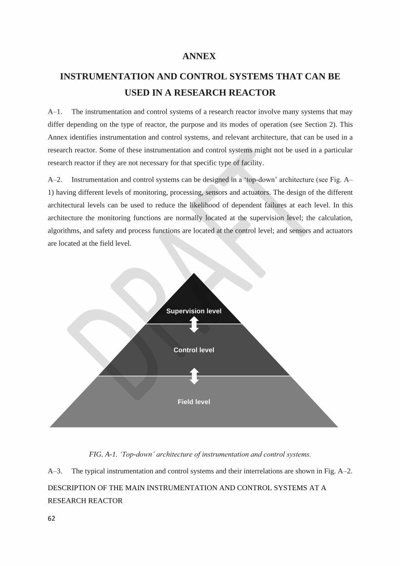
62
ANNEX
INSTRUMENTATION AND CONTROL SYSTEMS THAT CAN BE
USED IN A RESEARCH REACTOR
A–1. The instrumentation and control systems of a research reactor involve many systems that may
differ depending on the type of reactor, the purpose and its modes of operation (see Section 2). This
Annex identifies instrumentation and control systems, and relevant architecture, that can be used in a
research reactor. Some of these instrumentation and control systems might not be used in a particular
research reactor if they are not necessary for that specific type of facility.
A–2. Instrumentation and control systems can be designed in a ‘top-down’ architecture (see Fig. A–
1) having different levels of monitoring, processing, sensors and actuators. The design of the different
architectural levels can be used to reduce the likelihood of dependent failures at each level. In this
architecture the monitoring functions are normally located at the supervision level; the calculation,
algorithms, and safety and process functions are located at the control level; and sensors and actuators
are located at the field level.
FIG. A-1. ‘Top-down’ architecture of instrumentation and control systems.
A–3. The typical instrumentation and control systems and their interrelations are shown in Fig. A–2.
DESCRIPTION OF THE MAIN INSTRUMENTATION AND CONTROL SYSTEMS AT A
RESEARCH REACTOR
Supervision level
Control level
Field level

63
Reactor protection system
A–4. The reactor protection system is a set of components designed to monitor reactor operating
parameters (e.g. neutron power and period, coolant flow rate, inlet and outlet temperatures, pressure
drop in the reactor core), compare them with safety system settings and automatically initiate action of
the reactor shutdown system when the parameters reach or exceed the safety system settings. Each
parameter may be measured by two or more independent channels. The automatic actions are initiated
on the basis that the logic arrangement for the initiation of protective actions complies with the single
failure criterion. When three independent channels are available, the logic arrangement of two out of
three channels may be used to prevent the initiation of protective actions by spurious signals. A reactor
protection system could also be actuated manually by the reactor operator, by the experimenters or by
the control and monitoring system for irradiation and experimental devices. A trip of the reactor
protection system results in the shutdown of the reactor.
Note: CCTV — closed circuit television; COMMS — communication system; ESF — instrumentation
and control for initiation of other engineered safety features; HVAC — heating, ventilation and air-
conditioning for controlled and supervised areas; I&C — instrumentation and control; I&EDCMS —
control and monitoring system for irradiation facilities and experimental devices; Instr. —
instrumentation; PAMS — post-accident monitoring system; RCMS — reactor control and monitoring
system; RMS — radiation monitoring system; RPS — reactor protection system; VMS — vibration
monitoring system.
FIG. A–2. Research reactor instrumentation and control systems.
Instrumentation and control system for the initiation of other engineered safety features at a
research reactor
A–5. The instrumentation and control system for the initiation of engineered safety features is a set
of components designed to initiate, upon request, action of the emergency core cooling system, the decay
heat removal system, the confinement isolation system and the confinement heat removal system. The
64
system may also be actuated manually by the operator. A trip in the engineered safety features results
in the initiation of one or more of the actions mentioned above. The functions of the engineered safety
features may be included in the reactor protection system.
Post-accident monitoring system
A–6. A post-accident monitoring system is an important feature of for research reactors. Its purpose
is to provide the reactor operators and their backup teams with the information necessary for accident
management and to ensure that this information is reliable. Under accident conditions, reactor operators
may need information for the following purposes:
(a) To perform preplanned manual control actions for which no automatic control system is provided
and which are necessary to prevent or to mitigate the consequences of the accident. Such actions,
specified in the safety analysis report, are described in the accident management procedures.
(b) To determine whether important safety functions relating to reactivity control, core cooling,
integrity of the reactor coolant system, the heat sink, containment integrity and surveillance for
radioactivity are challenged, and whether they are being fulfilled by the reactor protection system,
the engineered safety features and their essential support systems.
(c) To relay information to, and to communicate effectively with, emergency response facilities on
the site.
Nuclear instrumentation at a research reactor
A–7. The nuclear instrumentation follows the value and evolution of the neutron flux of the reactor
in all its operational states, since this parameter is of most relevance to ensuring the safe operation of
the reactor. The nuclear instrumentation also provides the means to establish a suitable control strategy
for starting up the reactor and keeping it in stable operation at different power levels.
Reactor control and monitoring system
A–8. The reactor control and monitoring system is intended for the reliable monitoring of the
performance and the safe operation of the reactor. The reactor control and monitoring system provides
startup and automatic adjustment of power, compensates for fuel burnup and provides interlocks for safe
operation. The reactor control and monitoring system is built using fail-safe and redundant devices to
receive and process signals from a large number of sensors, to actuate the corresponding control drivers
and to present information on the reactor’s status for the reactor operator at the main control console of
the research reactor (the main human– machine interface).
A–9. The process instrumentation (detectors, sensors and switches), which measure process
parameters and the actual state (position) of actuators, and which are connected to the reactor control
and monitoring system, reside at the field level of the instrumentation and control systems.
Radiation monitoring system at a research reactor
65
A–10. The radiation monitoring system is designed for continuous radiation monitoring of the research
reactor as well as of surrounding areas for detecting the possible release of radioactive material. Such a
release might arise, for example, because of failures of technical equipment, loss of integrity of
protective barriers, loss of effectiveness of water purification systems, loss of confinement isolation or
failure of filters and ventilation systems.
HEATING, VENTILATION AND AIR-CONDITIONING SYSTEMS AT A RESEARCH
REACTOR
A–11. Heating, ventilation and air-conditioning systems are used to ensure and maintain adequate
environmental conditions for both personnel and equipment by providing temperature control and air
quality control. The ventilation system also helps in maintaining the radiological conditions, for example
by means of pressure gradients and the use of appropriate filters. Modern electronic equipment generates
much less heat than older types: nevertheless, excess temperature can still degrade performance. Air-
conditioning, as a means of removing excess heat from instrumentation and control systems that are
safety systems, needs to meet the design requirements specified for safety system support features. In
regions with a tropical climate or high levels of humidity, the proper design of ventilation systems (with
physical separation, redundancy and a closed cycle) might be the only way to eliminate a source of
potential common mode failure in instrumentation and control systems. In some facilities, the reactor
control and monitoring system has the capability to send commands remotely to the heating, ventilation
and air-conditioning systems (i.e. a command for the remote trip of the emergency ventilation system).
VIBRATION MONITORING SYSTEM AT A RESEARCH REACTOR
A–12. The vibration monitoring system provides a means of monitoring and detecting abnormal
vibrations in the main rotary equipment of the reactor. The reactor control and monitoring system is
used to transmit information from the vibration monitoring system to the control room.
CONTROL ROOMS FOR A RESEARCH REACTOR
A–13. Sufficient controls, indications, alarms and displays are provided in main control room to
initiate, supervise and monitor normal reactor operation and reactor shutdown to a safe state and to
provide assurance that a safe state has been reached and is being maintained.
A–14. The minimum provisions for the main control room, including the human–machine interfaces,
has to consider the need for the reactor operator to do the following:
(a) To operate the reactor safely in all its operational states;
(b) To monitor the safe operation of the reactor;
(c) To monitor the appearance of alarms;
(d) To perform and confirm a controlled shutdown;
(e) To actuate safety related systems;

66
(f) To perform and confirm a reactor trip;
(g) To perform and confirm the actuation of the engineered safety features;
(h) To monitor the status of fission product barriers;
(i) To keep the reactor in a safe shutdown mode;
(j) To implement emergency operating procedures.
A–15. The alarm annunciators show the status of systems. Safety systems have audible and visual
alarms on the reactor operator’s control console or control panel to provide a warning of any violation
of the operational limits and conditions. Reactor operators can access all signals through the main control
console of the reactor control and monitoring system. Control consoles and displays for the irradiation
facilities and experimental devices are usually located in the main control room.
A–16. The supplementary control room, where applicable, provides a possibility for remote shutdown
of the reactor in the event that this cannot be done from the main control room. Sufficient controls,
indications, alarms and displays are provided in the supplementary control room to be able to initiate,
supervise and monitor a reactor shutdown to a safe state and to provide assurance that a safe state has
been reached and is being maintained.
CONTROL AND MONITORING SYSTEM FOR IRRADIATION FACILITIES AND
EXPERIMENTAL DEVICES AT A RESEARCH REACTOR
A–17. The primary use of a research reactor is for the production of neutrons, for research purposes
and for the neutron irradiation of materials. Irradiation facilities include the equipment that is used to
place, move and arrange samples. A dedicated and tailored instrumentation and control system is
designed to control and monitor these operations. Irradiation facilities and experimental devices might
have an impact on the safe operation of the research reactor. The parameters of the experimental devices
that affect the safety of the reactor are displayed in the main control room. Trip signals from the control
and monitoring system for irradiation facilities and experimental devices to the reactor protection system
can also be provided as indicated by the safety analysis.
COMMUNICATION SYSTEMS AT A RESEARCH REACTOR
A–18. Communication systems are the link between the operating personnel in the main control room
and supplementary control rooms, the reactor hall and the process areas, the persons using the irradiation
facilities and experimental devices, and other internal locations (e.g. alarm stations) within the facility,
and for off-site emergency response organizations. A voice announcement system is used for making
announcements that can be heard by all on-site personnel, or to report an emergency or unforeseen
circumstances that necessitate an immediate response.
CLOSED CIRCUIT TELEVISION SYSTEMS AT A RESEARCH REACTOR
67
A–19. Closed circuit television is a useful aid that allows the reactor operator to monitor and supervise
relevant operational or maintenance tasks or activities that are being executed by the operating personnel
and can also be used for monitoring the security status of the facility.
INSTRUMENTATION AND CONTROL SYSTEMS FOR THE DETECTION AND SUPPRESSION
OF FIRES AT A RESEARCH REACTOR
A–20. The instrumentation and control system for the detection and suppression of fires is an
independent system that has the capability to detect a fire at the research reactor and then initiate
automatic fire suppression systems in the affected areas. Fire detection panels are located in the control
rooms to provide the reactor operators with relevant information.
ACCESS CONTROL SYSTEM AT A RESEARCH REACTOR
A–21. The access control system is part of the physical protection system for a research reactor and
has the capability to oversee and manage the movement of the personnel at the facility. Access control
panels may be located in the control rooms and/or in the central alarm stations to provide the reactor
operators with relevant information.
68
CONTRIBUTORS TO DRAFTING AND REVIEW
D’Arcy, A. Consultant, South Africa
Hargitai, T. Consultant, Hungary
McIvor, A. International Atomic Energy Agency
Morris, C. Consultant, Austria
Rao, D.V.H. International Atomic Energy Agency
Sears, D. F. International Atomic Energy Agency
Shokr, A.M. International Atomic Energy Agency
Sumanth, P.S. BARC, India
Sun, K. International Atomic Energy Agency