interconnect access to the telstra underground network
TRANSCRIPT

Interconnect Access to the Telstra Underground
Network
Interconnect Access to the Telstra
Underground Network
TELSTRA CORPORATION LIMITED (ABN 33 051 775 556) | PRINTED 26/05/2018
Final | TELSTRA INTERNAL | TM00042A01| INTERCONNECT ACCESS TO THE TELSTRA UNDERGROUND NETWORK
PAGE 1/38
Author’s name Access & Network Facilities Engineering Business unit Telstra Operations
Sub-business unit Networks Issue date 26 June 2018
Issue number 7 Telstra ID TM00042A01
Summary This Specification is to provide the Contractor with detailed Technical Requirements which must, unless otherwise directed by Telstra, be complied with in performing WUC (as defined in the General Conditions of Contract).

Interconnect Access to the Telstra Underground Network, Interconnect Access to the Telstra Underground Network (continued)
TELSTRA CORPORATION LIMITED (ABN 33 051 775 556) | PRINTED 26/05/2018
Final | TELSTRA INTERNAL | TM00042A01 | INTERCONNECT ACCESS TO THE TELSTRA UNDERGROUND NETWORK
PAGE 2/38
Contents
1 PURPOSE 4
2 SCOPE 4
3 TECHNICAL REQUIREMENTS 4
3.1 Preliminary Design 4
3.2 OHS in Congested Manholes and Pits (damage to plant and person) 4
3.2.1 Data Requirements 4
3.2.2 ACIF C524:2013 4
3.2.3 Scope 5
3.2.4 Use of Telstra Logo 5
3.3 Design 5
3.3.1 Subduct 5
3.3.2 Bare Optic Fibre Cable 6
3.3.3 Interconnection to Telstra Manholes and Pits – Breakouts 8
3.3.4 Installing Pits for Other Carriers 9
3.3.5 Separation between Telstra and Other Carriers Pits/Manholes 9
3.3.6 Material Management Process 9
3.3.7 Subduct and Conduit 9
3.3.8 Plugs - Conduit and Pipe 10
3.3.9 Cable and Joint Closure Housing – Fittings 10
3.3.10 Cable hauling Lubricant 10
3.3.11 Labelling of Plant 10
3.3.12 Recording of Plant 11
3.3.13 Plant Location 11
3.3.14 Manhole Preparation 12
3.3.15 Duct Breakout Installation 12
3.3.16 Subduct installation 13
3.3.17 Hauling Subduct and cables 17
3.3.18 Cable and Splice Closure Installation 19
3.3.19 Sealing Conduits, Breakouts and Subducts 21
3.3.20 Recording of Subduct and Other Carriers Plant within the Telstra Network 23
3.4 Commissioning/Acceptance 23
3.4.1 Quality Control System 23
3.4.2 Inspection 23
3.4.3 Handover 24
3.5 Recovery 24
3.5.1 Requirements after Cancellation of a Subduct Lease 24
4 MATERIAL LIST 25
5 REFERENCES 26
6 DEFINITIONS 26

Interconnect Access to the Telstra Underground Network, Interconnect Access to the Telstra Underground Network (continued)
TELSTRA CORPORATION LIMITED (ABN 33 051 775 556) | PRINTED 26/05/2018
Final | TELSTRA INTERNAL | TM00042A01 | INTERCONNECT ACCESS TO THE TELSTRA UNDERGROUND NETWORK
PAGE 3/38
7 ATTACHMENTS 28
CURRENT PRACTICE FOR BREAKOUT APPROVAL IN COFFIN SHAPED MANHOLES 28
Current Practice for Breakout Approval in Standard type Manholes (No Turret) 28
Manholes with a Turret 28
T-DUX SOLUTIONS 28
HAULING DETAIL SHEET 28
8 DOCUMENT CONTROL SHEET 29
APPENDIX 1 CURRENT PRACTICE FOR BREAKOUT IN COFFIN SHAPED MANHOLES 31
A1.1 Current Practice for Breakout in Standard type Manholes (No Turret) 32
A1.2 Manholes with a Turret 33
APPENDIX 2 T-DUX SOLUTIONS 34
APPENDIX 3 HAULING DETAIL SHEET 38

Interconnect Access to the Telstra Underground Network, Interconnect Access to the Telstra Underground Network (continued)
TELSTRA CORPORATION LIMITED (ABN 33 051 775 556) | PRINTED 26/05/2018
Final | TELSTRA INTERNAL | TM00042A01 | INTERCONNECT ACCESS TO THE TELSTRA UNDERGROUND NETWORK
PAGE 4/38
1 PURPOSE
The purpose of this Specification is to provide the Contractor with detailed Technical Requirements which must, unless otherwise directed by Telstra, be complied with in performing WUC (as defined in the General Conditions of Contract).
2 SCOPE
This Specification applies to the Design Elements and Deliverable Items (D.I.’s)
(Conduit)
This specification specifically refers to:
Interconnect Access to the Telstra Underground Network by Other Carriers
And refers to Contractors installing plant as part of the delivery of a wholesale product e.g. ducts access for other telecommunications Carriers and Carriage Service Providers, in the Telstra Underground Network.
Under the Facilities Access Agreement, the Carrier or Carriage Service Provider and Telstra jointly agree that an Approved Contractor perform the construction activity in a professional manner in accordance with Telstra Technical Specifications and Procedures whilst exercising due care, skill and judgement.
The order in which the Technical Requirements are set out in this Specification is listed below and corresponds with the order in which Deliverable Items (D.I.’s) are listed in the Schedules:
Preliminary Design
Design
Material
Installation Work
Commissioning/Acceptance
Cutover
Recovery
3 TECHNICAL REQUIREMENTS
3.1 Preliminary Design
3.2 OHS in Congested Manholes and Pits (damage to plant and person)
In the Design submission all manholes and pits that are Congested or unsafe to enter shall be recorded and Telstra advised, (The manhole/pit is not to be entered until Telstra have provided guidance).
3.2.1 Data Requirements
For all Ground Breaking activities Refer to Telstra’s “Working on or Adjacent to Underground Assets Procedure” & Contractors requiring access to data stored within Telstra systems shall request such access through the Telstra Business Unit “Data Services”.
3.2.2 ACIF C524:2013
Provides guidance on the basic principles of installation, maintenance and safety of external telecommunications networks; describes the minimum requirements for electrical, structural and network reliability and employee/public safety under specified conditions.

Interconnect Access to the Telstra Underground Network, Interconnect Access to the Telstra Underground Network (continued)
TELSTRA CORPORATION LIMITED (ABN 33 051 775 556) | PRINTED 26/05/2018
Final | TELSTRA INTERNAL | TM00042A01 | INTERCONNECT ACCESS TO THE TELSTRA UNDERGROUND NETWORK
PAGE 5/38
3.2.3 Scope
This Industry Code applies to persons who are:
(a) Owners of an external Communication Network covered by the Scope of the Code;
(b) Lessees of an external Communication Network covered by the Scope of the Code;
(c) Employees of the owners or lessees; and
(d) Contractors to the owners or lessees and persons employed by or subcontracted by such contractors.
The construction, maintenance, and safety provisions of this Industry Code apply to all external Communication Network systems whether or not the system is:
(a) (a) In service or out of service;
(b) (b) Being constructed and has never been Energised or operated in some form; or
(c) (c) Being constructed on or near other Utility infrastructure.
This Industry Code is intended to provide guidance on the basic principles of installation, maintenance and safety of external Communication Networks with the purpose of achieving the minimum requirements for electrical, structural and network reliability, as well as setting out the minimum provisions that are considered necessary for the safety of employees and the public under the specified conditions.
3.2.4 Use of Telstra Logo
The Telstra logo must not be used on any item of another Carrier’s plant.
3.3 Design
Subduct is the preferred method for carrier’s cable installations and should always be the first choice
for cable installations as a direct point to point reservation.
Bare Optic fibre cable in a street network can be only installed at Telstra’s discretion if no other
alternative exists and when integrity and serviceability of existing network is not jeopardised.
3.3.1 Subduct
Subducting allows maximum protection for other Carrier’s cables during and after installation, and during recovery of cables.
Accordingly, polyethylene (PE) subducts are to be installed to house other telecommunications Carriers’ cables installed in the Telstra underground network, with the following exceptions:
CBD tunnel systems in Melbourne and Sydney;
Exchange cable chambers;
To allow splice or loop installation in manholes that are deemed suitable locations by Telstra and approved in a Design & Construction Proposal or in a Construction Finalisation Document (CFD),
When a subduct cannot be made continuous from Telstra’s conduit network into a carrier P50mm breakout conduit,
Building lead-ins,
A subduct shall have a tensile strength and crush resistance, complying with AS/NZS 4130:2009 “Polyethylene (PE) pipes for pressure applications”.
Subducts installed in the Telstra network for the housing of other Carriers cables, remain the property of Telstra, and are leased by the Carrier.

Interconnect Access to the Telstra Underground Network, Interconnect Access to the Telstra Underground Network (continued)
TELSTRA CORPORATION LIMITED (ABN 33 051 775 556) | PRINTED 26/05/2018
Final | TELSTRA INTERNAL | TM00042A01 | INTERCONNECT ACCESS TO THE TELSTRA UNDERGROUND NETWORK
PAGE 6/38
3.3.2 Bare Optic Fibre Cable
OC Bare Optic fibre cable in a street network shall only be installed at Telstra’s discretion if no other alternative exists and when integrity and serviceability of existing network is not jeopardised
Telstra will permit customers to install Bare Optic fibre (B/F) where Subduct cannot be employed, providing maintenance and reservation can be met and not compromise the integrity of such pit/and or manhole. All Bare Optic fibre cables must be clearly labelled as per Telstra standards. (Carrier waives any liability towards Telstra if B/F is damaged) No other criteria is required or approval sought
Bare fibre is not to be installed in the last vacant duct and enough equivalent duct space must remain to enable replacement of the largest cable with either:
A cable of the same size and type, or
If the cable type is no longer available, then current equivalent cable type, or
If the cable size is no longer available, then next standard size up (eg. 300pr replaced by 400pr, 600pr by 800pr) or a combination of smaller cables equal in pair count to the old cable (eg. 600pr replaced by 400pr and 200pr).
Bare Optic fibre is to be installed in a duct that already has bare fibres, subducts or small copper cables not exceeding 200/0.40.
Satisfy existing duct reservations.
Satisfy cable hauling on existing projects under construction and future planned projects.
If one of the conditions cannot be satisfied then bare fibre should not be installed
Conduit Capacity: Greater than 70% occupied duct cannot be used for any additional cables
Large size bare fibre cable up to the size of a 32mm subduct shall be treated as an individual subduct.
Subduct Sizes
The standard subduct is PE 32 (28mm ID) subduct to AS/NZS 4130:2009 “Polyethylene (PE) pipes for pressure applications”.
Multi Subduct Joiner & sub ducts
Multi Subduct joiners should not be considered for manhole/pits with greater than 80% plant congestion. Consideration of subduct joint housing, sub duct flow and manhole/pit access will preclude such locations;
Only manholes and 9pits should be considered for MSJ installations
Multi Subduct joiners must not be installed in such a manner as to impede access and must be installed against the manhole wall supported by a bracket and oriented vertically (flat against the wall) below the lowest existing cable/joint;
Installation and maintenance of the multi subduct joiner should as far as is practical not require the relocation of existing plant within the manhole;
All multi subduct joiners and associated subducts must be labelled with the AS name used to establish the joiner;
All sub duct associated with the multi subduct joiner must as far as possible remain in a parallel configuration and avoid cross over’s or impeded other cables and conduits;
The associated subducts must be neatly routed around the walls of the M/H and be secured on existing or new cable bearers. It is preferred that the subducts be secured underneath the un-used cable bearers this will allow cables to be hauled on top of the cable bearers for future implementation;
New cable bearers are not to be installed in Telstra’s non-plastic pits. Multi subduct joiners are to be housed as close to the bottom of the non-plastic pit and as far up against the non-plastic pit wall as practicable and midway between the end walls, without blocking / interfering with the passage of the cable distribution runs.
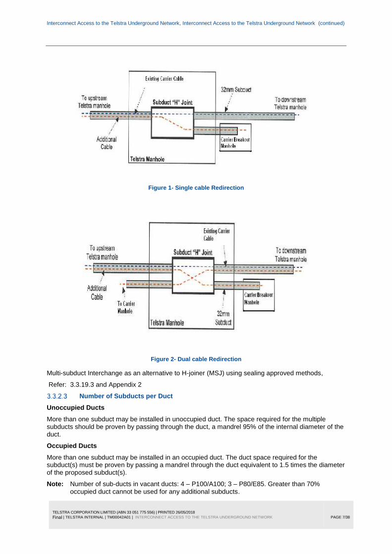
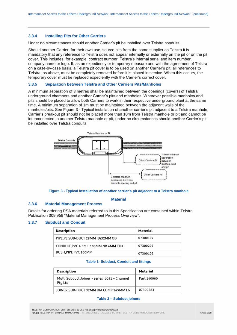
Typical multi subduct joiner schematic configurations.
Interconnect Access to the Telstra Underground Network, Interconnect Access to the Telstra Underground Network (continued)
TELSTRA CORPORATION LIMITED (ABN 33 051 775 556) | PRINTED 26/05/2018
Final | TELSTRA INTERNAL | TM00042A01 | INTERCONNECT ACCESS TO THE TELSTRA UNDERGROUND NETWORK
PAGE 7/38
Figure 1- Single cable Redirection
Figure 2- Dual cable Redirection
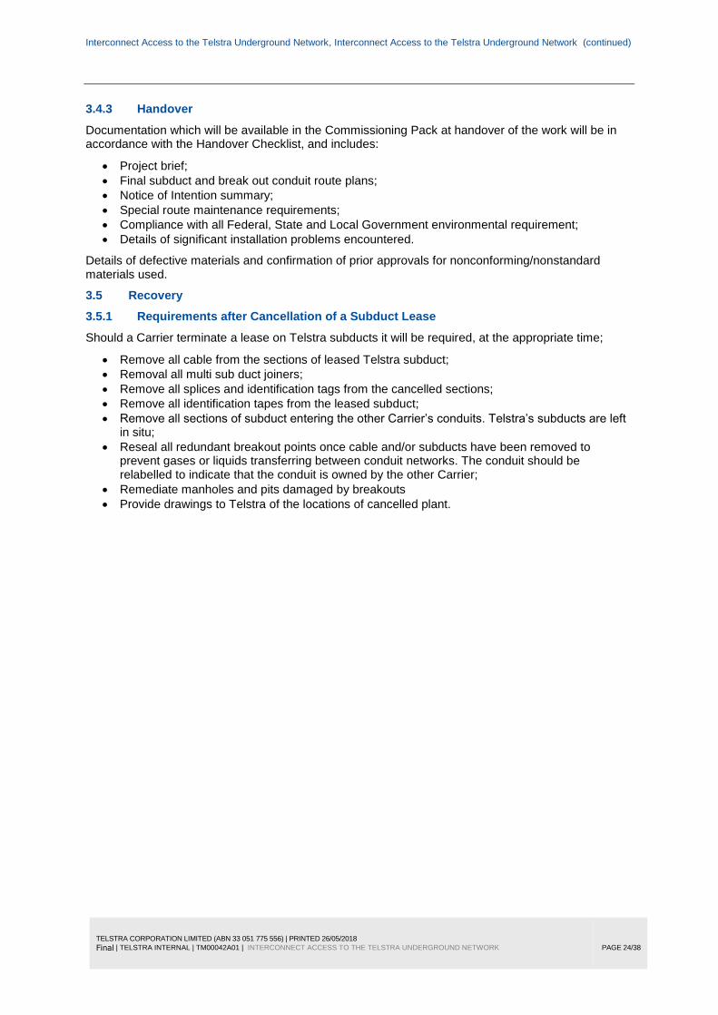
Multi-subduct Interchange as an alternative to H-joiner (MSJ) using sealing approved methods,
Refer: 3.3.19.3 and Appendix 2
Number of Subducts per Duct
Unoccupied Ducts
More than one subduct may be installed in unoccupied duct. The space required for the multiple subducts should be proven by passing through the duct, a mandrel 95% of the internal diameter of the duct.
Occupied Ducts
More than one subduct may be installed in an occupied duct. The duct space required for the subduct(s) must be proven by passing a mandrel through the duct equivalent to 1.5 times the diameter of the proposed subduct(s).
Note: Number of sub-ducts in vacant ducts: 4 – P100/A100; 3 – P80/E85. Greater than 70% occupied duct cannot be used for any additional subducts.

Interconnect Access to the Telstra Underground Network, Interconnect Access to the Telstra Underground Network (continued)
TELSTRA CORPORATION LIMITED (ABN 33 051 775 556) | PRINTED 26/05/2018
Final | TELSTRA INTERNAL | TM00042A01 | INTERCONNECT ACCESS TO THE TELSTRA UNDERGROUND NETWORK
PAGE 8/38
Length of subduct
Lengths of subduct may be joined to provide a continuous length limited only by the capacity to haul and handle the subduct, and the maximum hauling length of the cable to be installed within it.
Selection of Duct for Subducting
The selection of a duct for subducting must take the following considerations:
The duct has not been allocated for other cable or subduct installation
The cable and/or subduct flow will not block off other ducts, or interlace, obstruct or interfere with other cables or plant in the manhole.
The duct containing a copper cable larger than 200/0.40 or equivalent shall not be used if there are other alternatives.
The duct installed by NBN Co and tagged in a manhole or pit must not be selected.
The duct containing leaking air cored cable identifiable by a tag placed on a duct face of a manhole (IAL – Inaccessible Air Leak) must not be used.
The allocation of a duct in a nest of ducts for subduct installation, should generally follow by commencing with the bottom row of a nest, choosing the duct closest to the wall of the manhole where the cable or subduct is to be housed, and then occupying the remaining ducts in sequence in the row, before then selecting a duct from the next row following the same sequence.
3.3.3 Interconnection to Telstra Manholes and Pits – Breakouts
Overview
A breakout is installed in a Telstra manhole or pit where another Carrier’s conduit network is to be connected to Telstra’s underground network. Simply stated, it consists of a hole through a manhole/pit wall through which another Carrier’s conduit enters the manhole. As some breakouts are done in advance of a Carrier’s conduit construction a short length of starter conduit may be installed.
As a general rule, purpose built auxiliary manholes used to house repeaters or regenerators, Telstra exchange entry manholes (forming part of the exchange cable chamber), roadway manholes, underground electronics housings, small sized pits (not suitable for entry of 100mm conduit or the installation of fibre cable), tunnel entrance or shaft manholes and tunnels, are deemed to be unsuitable for breakouts. However, if no practical alternative exists, the Carrier may negotiate suitability on a site by site basis.
The minimum size pit for a break out conduit is a P5.
Breakout Conduit Type
While 100/4 PVC white telecommunications conduit is preferred for the majority of breakouts from Telstra manholes, 50mm PVC may also be requested by the access seeker and approved by Telstra at manholes. 50mm PVC may also be used where the situation renders it impractical or where Telstra pits are encountered that are not suitable for 100mm conduit installation. Only two sizes of breakout conduit are permitted – 100 and 50mm white PVC.
Other Carrier (OC) Lead-Ins
Where a Telstra manhole is located directly adjacent to a building’s foundations and the Carrier requires a new lead-in to the building, the breakout should not, in itself, constitute the lead-in. That is, the core bore should not extend through the manhole wall and the building batter. In this scenario, a breakout in the end wall must be done and the Carrier’s conduit extended to a suitable location away from the Telstra manhole where the new lead-in can be affected via a pit.
Interconnect Access to the Telstra Underground Network, Interconnect Access to the Telstra Underground Network (continued)
TELSTRA CORPORATION LIMITED (ABN 33 051 775 556) | PRINTED 26/05/2018
Final | TELSTRA INTERNAL | TM00042A01 | INTERCONNECT ACCESS TO THE TELSTRA UNDERGROUND NETWORK
PAGE 9/38
3.3.4 Installing Pits for Other Carriers
Under no circumstances should another Carrier’s pit be installed over Telstra conduits.
Should another Carrier, for their own use, source pits from the same supplier as Telstra it is mandatory that any reference to Telstra does not appear internally or externally on the pit or on the pit cover. This includes, for example, contract number, Telstra’s internal serial and item number, company name or logo. If, as an expediency or temporary measure and with the agreement of Telstra on a case-by-case basis, a Telstra pit cover is to be used on another Carrier’s pit, all references to Telstra, as above, must be completely removed before it is placed in service. When this occurs, the temporary cover must be replaced expediently with the Carrier’s correct cover.
3.3.5 Separation between Telstra and Other Carriers Pits/Manholes
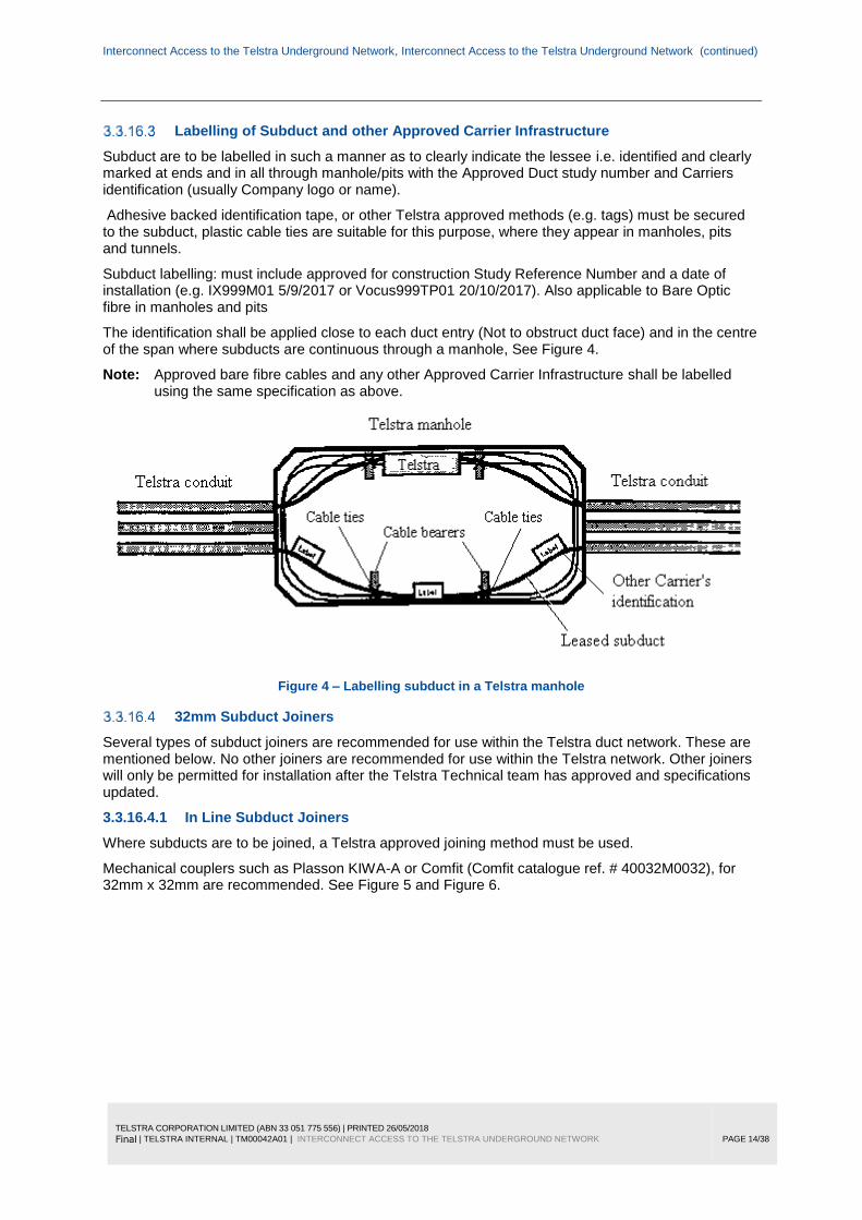
A minimum separation of 3 metres shall be maintained between the openings (covers) of Telstra underground chambers and another Carrier’s pits and manholes. Wherever possible manholes and pits should be placed to allow both Carriers to work in their respective underground plant at the same time. A minimum separation of 1m must be maintained between the adjacent walls of the manholes/pits. See Figure 3 - Typical installation of another carrier’s pit adjacent to a Telstra manhole. Carrier’s breakout pit should not be placed more than 10m from Telstra manhole or pit and cannot be interconnected to another Telstra manhole or pit, under no circumstances should another Carrier’s pit be installed over Telstra conduits.
Figure 3 - Typical installation of another carrier’s pit adjacent to a Telstra manhole
Material 3.3.6 Material Management Process
Details for ordering PSA materials referred to in this Specification are contained within Telstra Publication 009 959 “Material Management Process Overview”.
3.3.7 Subduct and Conduit
Description Material
PIPE,PE SUB-DUCT 28MM ID/32MM OD 07300107
CONDUIT,PVC 4.5M L 100MM NB 4MM THK 07300207
BUSH,PIPE PVC 100MM 07300102
Table 1- Subduct, Conduit and fittings
Description Material
Multi Subduct Joiner - series ILC41 – Channel Pty Ltd
Part 140060
JOINER,SUB-DUCT 32MM DIA COMP 145MM LG 07300283
Table 2 – Subduct joiners

Interconnect Access to the Telstra Underground Network, Interconnect Access to the Telstra Underground Network (continued)
TELSTRA CORPORATION LIMITED (ABN 33 051 775 556) | PRINTED 26/05/2018
Final | TELSTRA INTERNAL | TM00042A01 | INTERCONNECT ACCESS TO THE TELSTRA UNDERGROUND NETWORK
PAGE 10/38
3.3.8 Plugs - Conduit and Pipe
Description Material
PLUG,CONDUIT PE 100MM 07300044
Conduit Plug -Pressure Type 438/00024
PLUG,PIPE EPDM 20MM NOM 07300216
PLUG,PIPE EPDM 35MM NOM 07300217
PLUG,PIPE EPDM 50MM NOM 07300218
INSTALLATION TOOL,TDUX SEALING SYSTEM 07300160
DUCT SEALING SYSTEM,WRAPAROUND TDUX45 07300193
DUCT SEALING SYSTEM,WRAPAROUND TDUX60 07300194
DUCT SEALING SYSTEM,WRAPAROUND TDUX100 07300196
CLIP,DUCT TDUX-CL-20 BOX OF 5 07300199
CLIP,DUCT TDUX-CL-60 BOX OF 5 07300227
GAS CYLINDER,CO2 TDUX INFLATION 07300229
Table 3 - Conduit and Pipe Sealing Plugs
3.3.9 Cable and Joint Closure Housing – Fittings
Description Material
BEARER,CABLE MOVABLE 75MM 42600005
BEARER,CABLE MOVABLE 125MM 42600006
BEARER,CABLE MOVABLE 255MM 42600007
BEARER,CABLE MOVABLE 370MM 42600008
BEARER,CABLE MOVABLE 480MM 42600009
Expansion Anchor ½” 089/00011
Table 4 – Cable and Joint Housing Fittings
3.3.10 Cable hauling Lubricant
Description Material
LUBRICANT,CABLE TYPE A POLYWATER 09100030
Table 5 – Cable hauling Lubricant
3.3.11 Labelling of Plant
All other Carrier’s plant installed in the Telstra network (e.g. subduct, bare fibre, breakout, loop, etc.) shall be labelled to identify the Carrier, the Study Reference Number approved for construction and install date, e.g.
OPTUS TELD0999M01 11/04/2017 or
TPG IX99999TP03 09/10/2015
Identification tapes, markers and tags are to be provided by the Acquiring Carrier.
All other Carrier’s plant installed in the Telstra network should be suitably labelled to identify the Carrier. Identification tapes, markers and tags are to be provided by the Acquiring Carrier.

Interconnect Access to the Telstra Underground Network, Interconnect Access to the Telstra Underground Network (continued)
TELSTRA CORPORATION LIMITED (ABN 33 051 775 556) | PRINTED 26/05/2018
Final | TELSTRA INTERNAL | TM00042A01 | INTERCONNECT ACCESS TO THE TELSTRA UNDERGROUND NETWORK
PAGE 11/38
3.3.12 Recording of Plant
Plant installed for interconnect access shall be recorded in Telstra Physical Network Inventory database (TPNI).
It includes:
Cables occupying trays in CBD tunnels or Exchange cable chambers;
Subducts and/or bare fibre housed in conduits;
Breakouts i.e. manholes or pits where breakout ducts connect to other carrier’s networks;
Equipment manholes i.e. Telstra manholes used to accommodate items of other carriers equipment e.g. joints/splices, cable loops, multi-subduct joiners etc.
Duct configuration and used duct for each conduit run used by other carrier
It is the responsibility of a Carrier or Carrier’s authorised Contractor to provide the appropriate data for these systems at the end of construction.
Within a timeframe specified in a Commercial Agreement an As-built plan, manhole layouts and other required documents (e.g. photos, approval for augmentation or scope variation or one-off exemption to standards or specifications etc. as applicable) must be submitted to Telstra.
Telstra will verify this data and arrange the necessary systems input.
All additions or alterations to Telstra network plant shall be recorded in the appropriate Telstra Systems. It is the responsibility of the Telstra’s Contractor to input the appropriate data to these systems prior to commissioning and handover. Contractors shall arrange the necessary systems access/data input by contacting the appropriate regional Contractor Data Centre.
When recording or altering details in Telstra Systems, the requirements in the Telstra Publication 013 310 “Contract Identification – Contractor Database Requirements” are mandatory.
Recording of Subduct and Other Carriers Plant within the Telstra Network
Plant installed for interconnect access eg joints/loops, subducts, subduct joiners and breakouts, and other carriers plant is to be recorded in the Cadlink and TPNI databases.
Plant to be recorded includes:
Cables occupying trays in CBD tunnels or Exchange cable chambers;
Subducts and subduct joiners;
Breakout manholes i.e. manholes where breakout ducts connect to other carrier’s networks;
Equipment manholes i.e. Telstra manholes used to accommodate items of other carriers equipment eg joints, repeaters, cable loops etc.
Duct reservations shall be recorded in TPNI (valid for 90 Business days)
3.3.13 Plant Location
Locating underground assets
Before any excavation works are to be carried out all constructors shall comply with;
Working on or Adjacent to Underground Assets Procedure
And complete
Working on or Adjacent to Underground Assets Permit
Clearing Impediments to Physical Access to Telstra Plant
Telstra is not responsible for locating buried manholes but will help with information from plans, if necessary. Similarly, removal of water or dirt covering the manhole lids, removal of grass or weeds growing over manhole lids, moving vehicles parked over manholes or gaining access to manholes having their entrances impeded by temporary structures is the responsibility of the other Carrier or its contractor.

Interconnect Access to the Telstra Underground Network, Interconnect Access to the Telstra Underground Network (continued)
TELSTRA CORPORATION LIMITED (ABN 33 051 775 556) | PRINTED 26/05/2018
Final | TELSTRA INTERNAL | TM00042A01 | INTERCONNECT ACCESS TO THE TELSTRA UNDERGROUND NETWORK
PAGE 12/38
3.3.14 Manhole Preparation
To ensure safe and successful installations, the following manhole preparation and procedures must be carried out before and during installation work:
Apply all relevant safety precautions including gas detection and manhole rescue procedures, before opening, entering and working in the manhole;
Examine winching entry and exit points and flow for winch ropes, subduct and cable, and position to avoid any damage to the manhole, cable, subduct and other plant or equipment contained within the manhole;
Ensure secure attachment and placement of cable blowing equipment to avoid any damage to cables or equipment;
It is acceptable to temporarily shift cables, closures, ladders or other plant which may be in the way of the hauling path, if no other option exists and providing that there is no possible risk to Telstra plant. Any item of plant temporarily shift must be relocated and secured back in its original position;
If there is any possible risk of damage to Telstra plant, the contractor must arrange for Telstra to temporarily shift and then relocate the plant, at the Contractors expense;
Subduct or cable or subduct joiner must not be left unsupported, or lying on the floor of the manhole.
Removal of Redundant Cable
Under certain circumstances, Telstra may withdraw redundant cable from its conduit network in order to make the duct available for subducting by another Carrier. Telstra will be responsible for removing the redundant cable, Refer to Work Instruction: 010265W06 Cable Recovery from Telstra Network for approved removal practices.
3.3.15 Duct Breakout Installation
Installation in Manholes
Breakout points should generally be located in the end walls of manholes. Where connection is required to a point adjacent to a manhole, and end entry is not practical i.e. due to the position of the other Carriers facility e.g. pit /manhole, or the end wall of the Telstra manhole is heavily congested, then side wall entry shall be negotiated with Telstra on a case by case basis.
The breakout point should preferably be located a minimum of 300mm from the manhole roof and nearest wall.
The breakout hole in a manhole should be provided by core boring, at the outside diameter of the interconnect conduit, to provide a neat fit for the conduit.
Where core boring is not possible, the breakout should be provided in a manner so to restrict damage, cracking and breakage of the manhole wall to the absolute minimum to allow the conduit installation. The manhole wall must be reinstated to restore it to a durable, smooth and neat finish.
Conduit bushes must be fitted to all Telstra Manhole entries. Any gap between the conduit and manhole wall must be sealed with cement grout.
Installation in Pits
Breakouts should always be done in the ends of Telstra pits to minimise bending radii. Where a Carrier wishes to install conduits at right angles from the pit, a suitable PVC bend must be used at the breakout point.
Breakout entries into cement or plastic pits must be sealed to prevent silt etc. entering the pit.
Conduit bushes must be fitted at all Telstra pit entries.
Breakout are not permitted if the pit already has the maximum allowable number of conduit entries at each end. Refer 015526A09 Breakout from Telstra Pits, Figure 3, 4 & 5.

Interconnect Access to the Telstra Underground Network, Interconnect Access to the Telstra Underground Network (continued)
TELSTRA CORPORATION LIMITED (ABN 33 051 775 556) | PRINTED 26/05/2018
Final | TELSTRA INTERNAL | TM00042A01 | INTERCONNECT ACCESS TO THE TELSTRA UNDERGROUND NETWORK
PAGE 13/38
3.3.16 Subduct installation
Installing Sub-ducts
A subduct shall be installed in a conduit, without any deformation, necking or stretching.
To enable maximum hauling distance for cables, subduct must be installed to avoid excessive bends, and abrupt changes of direction.
Where a subduct passes through a manhole, it shall be neatly racked and housed against the wall with smooth gradual curves, and provide as close as possible a straight through appearance, that will least affect the cable hauling tension.
The tensile strength shall be such that it can meet all potential cable installation requirements, including cable/hauling line blowing techniques to a blowing pressure of 700 kPa. (100 psi).
Once installed a subduct shall allow passage of a mandrel equal to 95% of the internal diameter of the subduct.
At Exchange entry manholes or Exchange cable chambers, ducts in which subducts are installed must be sealed with an appropriate duct sealing system.
Subducts terminating in the Telstra underground network, including in exchange cable chambers and tunnels must be sealed to prevent gases, liquids or other substances entering the Telstra network, or passing to other Carriers networks.
For details of conduit and subduct sealing refer 3.3.19.
Blocked ducts
The Carrier’s contractors should install subducts only as indicated on an approved Design & Construction Proposal. During construction, where ducts are found to be blocked or damaged, the Carrier’s contractor shall contact the Telstra Duct Access Team for appropriate direction. Refer 010260W02
Works performed under DCAF allows the Carrier/contractor to choose an alternative Duct without consulting Telstra DUCT Access Team. Carrier /Contractor must ensure all Technical standards, maintenance standards & reservations have been accounted for. Carrier /Contractor must mark on the As-built plan and TM sheets the blocked Duct and the distance to the blockage from adjacent manholes or pits from both ends.
Interconnect Access to the Telstra Underground Network, Interconnect Access to the Telstra Underground Network (continued)
TELSTRA CORPORATION LIMITED (ABN 33 051 775 556) | PRINTED 26/05/2018
Final | TELSTRA INTERNAL | TM00042A01 | INTERCONNECT ACCESS TO THE TELSTRA UNDERGROUND NETWORK
PAGE 14/38
Labelling of Subduct and other Approved Carrier Infrastructure
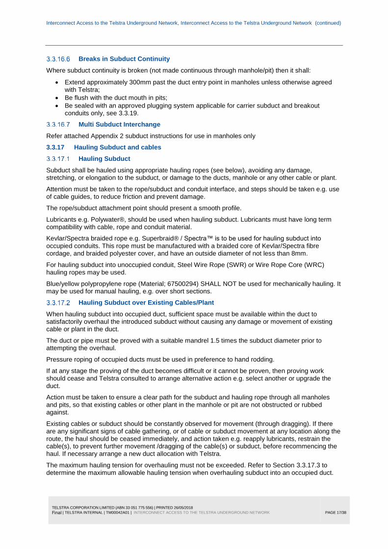
Subduct are to be labelled in such a manner as to clearly indicate the lessee i.e. identified and clearly marked at ends and in all through manhole/pits with the Approved Duct study number and Carriers identification (usually Company logo or name).
Adhesive backed identification tape, or other Telstra approved methods (e.g. tags) must be secured to the subduct, plastic cable ties are suitable for this purpose, where they appear in manholes, pits and tunnels.
Subduct labelling: must include approved for construction Study Reference Number and a date of installation (e.g. IX999M01 5/9/2017 or Vocus999TP01 20/10/2017). Also applicable to Bare Optic fibre in manholes and pits
The identification shall be applied close to each duct entry (Not to obstruct duct face) and in the centre of the span where subducts are continuous through a manhole, See Figure 4.
Note: Approved bare fibre cables and any other Approved Carrier Infrastructure shall be labelled using the same specification as above.
Figure 4 – Labelling subduct in a Telstra manhole
32mm Subduct Joiners
Several types of subduct joiners are recommended for use within the Telstra duct network. These are mentioned below. No other joiners are recommended for use within the Telstra network. Other joiners will only be permitted for installation after the Telstra Technical team has approved and specifications updated.
3.3.16.4.1 In Line Subduct Joiners
Where subducts are to be joined, a Telstra approved joining method must be used.
Mechanical couplers such as Plasson KIWA-A or Comfit (Comfit catalogue ref. # 40032M0032), for 32mm x 32mm are recommended. See Figure 5 and Figure 6.

Interconnect Access to the Telstra Underground Network, Interconnect Access to the Telstra Underground Network (continued)
TELSTRA CORPORATION LIMITED (ABN 33 051 775 556) | PRINTED 26/05/2018
Final | TELSTRA INTERNAL | TM00042A01 | INTERCONNECT ACCESS TO THE TELSTRA UNDERGROUND NETWORK
PAGE 15/38
Figure 5 – Typical subduct joiners
Figure 6 - Expanded view of Comfit 32mm subduct joiner
Welding methods such as butt fusion are also acceptable. The method used should result in a join that has no internal lip and, consequently, maintains the original internal dimensions of the subduct. Heat shrink sleeve technologies must not be used to join subducts in the Telstra underground network. Joins in subduct are to be capable of withstanding a maximum cable blowing installation pressure of 700 kPa.
All joiners are to be placed in manholes, pits or chambers. Joiners shall not be placed in ducts between manhole, pits or chambers.
3.3.16.4.2 Multiple Subduct Joiner
This type of subduct joiner is intended for installation into suitable Telstra manholes/pits and enables 3 or 4 subducts to be joined into the enclosure at breakout points. These subduct joint enclosures are openable and used to redirect an incoming OF cable to one of two outgoing subducts. An example of such a Telstra approved multi subduct joiner is the Optus “H” closure series ILC41.
Multi Subduct Joiners other than the ILC41 can only be used if approved by the Telstra Technical team. Technical and installation specification documentation must be submitted for approval to Telstra prior to use in the network. The installation of a multi subduct joiner must be flush to the manhole/pit wall and clear of other plant within the manhole pit. Subducts must flow to and from the joiner in accordance with 3.3.16.1 above and 3.3.16.5 below.
In Telstra’s non-plastic pits, multi subduct joiners are to be housed as close to the bottom of the non-plastic pit and in the middle – between end walls, without blocking / interfering with the passage of the cable distribution runs, Refer: 3.3.6.3 for labelling specifications.

Interconnect Access to the Telstra Underground Network, Interconnect Access to the Telstra Underground Network (continued)
TELSTRA CORPORATION LIMITED (ABN 33 051 775 556) | PRINTED 26/05/2018
Final | TELSTRA INTERNAL | TM00042A01 | INTERCONNECT ACCESS TO THE TELSTRA UNDERGROUND NETWORK
PAGE 16/38
Figure 7 – Typical Installed Multi Subduct joiner
Figure 8 – Typical Multi Subduct Joiner kit
Housing Subduct in Manholes
Subduct passing through intermediate manholes shall be splayed towards the nearest side wall of the manhole and secured in that position.
The subduct shall be housed with smooth bends, avoiding excessive bending or curvature or abrupt changes in direction, to provide as close as possible a straight through appearance that will least affect the cable installation tension.
Subduct shall be securely fastened to cable bearers with plastic cable ties.
Note: Where no cable bearers are installed the Contractor shall install them as required in each location for their installation and report to Telstra any existing non-conformance. Refer; 010254W06 Installation of Jointing Pits and Manholes for installation of Cable Bearers.
Subduct must not obstruct access to cables, joint closures, other conduit entrances or other equipment in the manhole. To avoid confusion any cable, joint, sub duct or subduct joiner must not block off other ducts, or interlace, obstruct or interfere with other cables or plant in the manhole.
Multiple subduct joiner
against
manhole wall
Interconnect Access to the Telstra Underground Network, Interconnect Access to the Telstra Underground Network (continued)
TELSTRA CORPORATION LIMITED (ABN 33 051 775 556) | PRINTED 26/05/2018
Final | TELSTRA INTERNAL | TM00042A01 | INTERCONNECT ACCESS TO THE TELSTRA UNDERGROUND NETWORK
PAGE 17/38
Breaks in Subduct Continuity
Where subduct continuity is broken (not made continuous through manhole/pit) then it shall:
Extend approximately 300mm past the duct entry point in manholes unless otherwise agreed with Telstra;
Be flush with the duct mouth in pits;
Be sealed with an approved plugging system applicable for carrier subduct and breakout conduits only, see 3.3.19.
Multi Subduct Interchange
Refer attached Appendix 2 subduct instructions for use in manholes only
3.3.17 Hauling Subduct and cables
Hauling Subduct
Subduct shall be hauled using appropriate hauling ropes (see below), avoiding any damage, stretching, or elongation to the subduct, or damage to the ducts, manhole or any other cable or plant.
Attention must be taken to the rope/subduct and conduit interface, and steps should be taken e.g. use of cable guides, to reduce friction and prevent damage.
The rope/subduct attachment point should present a smooth profile.
Lubricants e.g. Polywater®, should be used when hauling subduct. Lubricants must have long term compatibility with cable, rope and conduit material.
Kevlar/Spectra braided rope e.g. Superbraid® / Spectra™ is to be used for hauling subduct into occupied conduits. This rope must be manufactured with a braided core of Kevlar/Spectra fibre cordage, and braided polyester cover, and have an outside diameter of not less than 8mm.
For hauling subduct into unoccupied conduit, Steel Wire Rope (SWR) or Wire Rope Core (WRC) hauling ropes may be used.
Blue/yellow polypropylene rope (Material; 67500294) SHALL NOT be used for mechanically hauling. It may be used for manual hauling, e.g. over short sections.
Hauling Subduct over Existing Cables/Plant
When hauling subduct into occupied duct, sufficient space must be available within the duct to satisfactorily overhaul the introduced subduct without causing any damage or movement of existing cable or plant in the duct.
The duct or pipe must be proved with a suitable mandrel 1.5 times the subduct diameter prior to attempting the overhaul.
Pressure roping of occupied ducts must be used in preference to hand rodding.
If at any stage the proving of the duct becomes difficult or it cannot be proven, then proving work should cease and Telstra consulted to arrange alternative action e.g. select another or upgrade the duct.
Action must be taken to ensure a clear path for the subduct and hauling rope through all manholes and pits, so that existing cables or other plant in the manhole or pit are not obstructed or rubbed against.
Existing cables or subduct should be constantly observed for movement (through dragging). If there are any significant signs of cable gathering, or of cable or subduct movement at any location along the route, the haul should be ceased immediately, and action taken e.g. reapply lubricants, restrain the cable(s), to prevent further movement /dragging of the cable(s) or subduct, before recommencing the haul. If necessary arrange a new duct allocation with Telstra.
The maximum hauling tension for overhauling must not be exceeded. Refer to Section 3.3.17.3 to determine the maximum allowable hauling tension when overhauling subduct into an occupied duct.

Interconnect Access to the Telstra Underground Network, Interconnect Access to the Telstra Underground Network (continued)
TELSTRA CORPORATION LIMITED (ABN 33 051 775 556) | PRINTED 26/05/2018
Final | TELSTRA INTERNAL | TM00042A01 | INTERCONNECT ACCESS TO THE TELSTRA UNDERGROUND NETWORK
PAGE 18/38
Overhauling – Maximum Allowable Hauling Tension
When installing subduct or cable in occupied duct, the maximum allowable hauling tension must be determined prior to any overhauling, by:
Determining the maximum hauling tensions of all the existing cables in the conduit or pipe (Refer to Table 6 and Table 7)
And, of all the hauling tensions, haul to the lowest maximum tension, or where small sized twisted pair cables exist (<100/0.40) haul to a maximum of 2 Kn;
To limit the hauling tension, a mechanical hauling fuse rated at the lowest hauling tension, or an equivalent tension limiting device must be used.
If during a haul the tension begins to exceed the maximum hauling tension previously determined, the haul must stop immediately. Do not continue, until appropriate action has been taken to reduce the hauling tension.
Table 5 provides the maximum hauling tensions for optical fibre cables.
Cable Type Fibre Count Maximum Hauling Tension
Standard Cable 6 -60 120 & 288
2Kn (2,000 Newtons) 4Kn (4,000 Newtons)
High Strength 6 -60 120
4Kn 5Kn
Aerial 6 -36 5Kn
Underwater 6 – 120 30Kn
Rodent Proof Dielectric
6 –60 120
4Kn 5Kn
Internal Tie 6 – 120 2Kn
Table 6 – Maximum Hauling Tensions
Table 6 provides the maximum hauling tensions for twisted pair (copper) cables.
Cable Size/Type Max. Hauling Tension
100/0.40 2.4Kn
200/0.40 4.8Kn
400/0.40 9.6Kn
800/0.40 19.2Kn
1200/0.40 28.8Kn
2400/0.40 40.0Kn
200/0.64 12.3Kn
400/0.64 24.6Kn
Table 7 – Copper Cable Hauling Tensions
For standard copper cables not included in Table 6 above, maximum hauling tensions can be calculated using the formula:
Tension = 150 Pd2 Newtons (where P = no. of pairs, d = conductor diam. In mm)

Interconnect Access to the Telstra Underground Network, Interconnect Access to the Telstra Underground Network (continued)
TELSTRA CORPORATION LIMITED (ABN 33 051 775 556) | PRINTED 26/05/2018
Final | TELSTRA INTERNAL | TM00042A01 | INTERCONNECT ACCESS TO THE TELSTRA UNDERGROUND NETWORK
PAGE 19/38
Overhauling – Care of existing plant
The existing network must be cared for at all times and not interfered with during the course of installation of either rods, rope, subduct or cables;
If existing cables and/or joints need to be moved during work, they must be handled carefully and replaced correctly in the pit on completion of the task;
Lead cables are fragile and can be easily damaged. They should not be moved and extreme care must be taken when working around them;
Avoid lacing the rope through existing cables, as this will cause undue pressure to be inserted upon them.
Hauling Winch Requirements / Compliance
Cable winches used in the Telstra Network shall meet all requirements and compliance as stated in TM00044 A01* - Optic Fibre Winch Compliance
Hauling Detail Sheet
Should overhauling of existing air pressurised cables be required a Hauling Detail Sheet must be submitted. See Attachment 1.
The following details should be completed and forwarded, by e-mail, to the Cable Pressurisation Management Centre, 24 hours before hauling commences:
o Contractor name and on site supervisors contact point; o Exchange name, DA (Distribution Area), Cable number and pair range of existing cables; o Location; o Duration of haul; o Work Order Number; o Current pressure of existing cables to be overhauled.
A copy of the Hauling Detail Sheet must be on site when work is in progress. The remaining details shall be completed and included with the “as built” file returned to Telstra upon completion of the project.
Confirm that all pressurised air-cored cables have been tested both prior to and after hauling to ensure they maintain air pressure.
The Cable Pressurisation Monitoring Centre contact details are:
E-mail: [email protected] (! IS CPAS National Network Access)
Phone: 1300 556 727
3.3.18 Cable and Splice Closure Installation
Refer to TM00043 Copper cable and TM00044 Optic Fibre for cable and splice closure installation and housing details.
Movement of Subduct to install cables
Where subduct is released and moved from a manhole wall or cable bearers, to provide a more straight-through appearance to assist reducing the hauling tension of cable being installed within the subduct, the subduct must be rehoused correctly and secured back into its original position.
Cable Loops (Coils)
Suitability of individual manholes for housing cable loops will be assessed by Telstra or Accredited Carrier contractor.
Cable loops (coils of cable) are not permitted in pits, tunnels, Exchange cable chambers, riser shafts, regenerator or repeater manholes, or congested manholes.
Cable loops left in manholes are to be installed vertically and housed neatly against manhole walls, and secured to manhole walls so as not to obstruct access to existing cable closures and cable loops, cable bearers and other fittings provided for future cables and closures.

Interconnect Access to the Telstra Underground Network, Interconnect Access to the Telstra Underground Network (continued)
TELSTRA CORPORATION LIMITED (ABN 33 051 775 556) | PRINTED 26/05/2018
Final | TELSTRA INTERNAL | TM00042A01 | INTERCONNECT ACCESS TO THE TELSTRA UNDERGROUND NETWORK
PAGE 20/38
Where splice closures are installed sufficient looped cable should be left to enable the splice closure to be removed from the manhole for splicing etc. operations.
Under no circumstances will loops exceed 40m.
Access to conduit entrances must not be obstructed so as not to inhibit subsequent cable installation.
Cable loops shall not be left unsupported or lying on the floor of a manhole, to avoid being damaged by installation staff, manhole ladders, lids and other accessories.
Housing Cables and Joint/Splice Closures
Suitability of individual manholes for housing cable joint closures will be assessed by Telstra or Accredited Carrier contractor.
Joint closures will not be permitted in pits and congested manholes.
Locating closures in manholes specifically for containment of Telstra repeater or regenerator housings is not permitted.
Where in-line splice closures are used they are to be housed horizontally on bearers at the appropriate level in the manhole.
Where single-ended splice closures are used, they shall be mounted in a suitable position on the manhole wall using an appropriate bracket.
The cables entering the splice closure must not be intertwined with existing cables or housed in such a way as to risk intertwining with future cables.
Closures and their associated cables must not obstruct access to existing closures and cable loops, or interfere with the installation of subsequent cables and closures.
All closures must be mounted and secured to support brackets or cable bearers.
Securing Cable Loops and Splice Closures in Manholes
Splice closures and their associated cables must be fully supported and secured to the cable bearers or manhole walls, so that there is no likelihood of them being dislodged or becoming loose.
Cable bearers including the making of any masonry anchorage points will be installed as required to provide the support and securing of cables and joint/splice closures.
Bearers may be attached directly to the manhole wall or be secured to Unistrut members.
Bearer length will depend on the number and size of cable to be housed.
Anchors and bearers must be installed so as to not interfere with or obstruct the housing or access to existing cables or other plant in the manhole.
In manholes where Unistrut or similar support members are provided, splice closures may be supported on these members.
Labelling of Other Carrier’s Cables
Cable loops and cable joint/splice closures must be clearly labelled. And include approved for construction Study Reference Number and a date of installation (e.g. IX999M01 5/9/2017 or Vocus999TP01 20/10/2017). Also applicable to Bare Optic fibre in cable chambers, manholes and pits.
At locations where the other Carrier’s fibre cable is not subducted it must be clearly identified. This includes CBD tunnels, Exchange cable chambers, POI (Point Of Interconnect) and TEBA (Telstra Equipment Building Access) space.
Adhesive backed tape or tags bearing the owning Carrier’s identification (usually Company logo or name) and attached by plastic cable ties are suitable for this purpose.

Interconnect Access to the Telstra Underground Network, Interconnect Access to the Telstra Underground Network (continued)
TELSTRA CORPORATION LIMITED (ABN 33 051 775 556) | PRINTED 26/05/2018
Final | TELSTRA INTERNAL | TM00042A01 | INTERCONNECT ACCESS TO THE TELSTRA UNDERGROUND NETWORK
PAGE 21/38
Installations in Tunnels and Exchange Cable Chambers
All practices and procedures for access and for working in tunnels, and Exchange cable chambers (special work locations) must be complied with.
Installation of other Carriers cable or other plant must not obstruct or interfere with existing Telstra plant.
Housing Cables and Closures in Tunnels, Exchange Entry Manholes and Cable chambers, POI and TEBA
Cables installed in Exchange chambers, tunnels and into POI or TEBA space are not to be subducted. Cables are to follow existing riser shafts and fibre trays and are to be installed in a professional manner. Where tray work internal to the Exchange is inadequate to house a new cable, the Carrier is responsible for supplying any additional requirements.
Telstra will provide any tray work, bearers or ironwork in CBD tunnels and Exchange chambers.
Fixing by other Carriers or contractors will be limited to securing cable or closures to racking or trays using approved cable ties.
Unless otherwise agreed with Telstra, cable joint or splice closures will not be permitted in Exchange entry manholes, cable chambers or tunnels.
Cable sheaths must be clearly identified at, locations where the cable changes direction or elevation, duct entry/exit points, cable loops and all other locations where deemed necessary by Telstra.
Secondary Protection
In areas such as cable tunnels and exchange cable chambers, secondary protection to the other carrier’s cables may be installed, to prevent accidental damage to the other carrier’s cable due to activities in close proximity. The requirement to install this secondary protection is at the other carrier’s discretion.
Two types of secondary protection are approved for use in the Telstra Network:
50mm Agflow Pipe (black);
25mm White Corrugated Conduit.
3.3.19 Sealing Conduits, Breakouts and Subducts
Sealing Conduits and Breakouts
As specified in this document, conduits and breakout conduits containing subducts are to be sealed with an appropriate sealing system. E.g. TDUX Inflatable Sealing System, or Tyco “Jackmoon” expandable Multi Port Sealing Devices (Triplex and Quadplex Plugs), Filoform Duct Sealant.
Expandable foam type blockers must not be used.
Vacant breakout conduits are to be sealed using appropriate plugs e.g. Tapered PE or pressure type plug Figure 10, or TDUX, Filoform Duct Sealant.
Where a breakout is installed in a Telstra manhole/pits and the subduct is to be made continuous into the other Carrier’s conduit network, the breakout and the subduct should be sealed to prevent gas or liquids escaping between networks via either the subduct or the conduit. The conduit is sealed at the breakout point, whilst the subduct should be sealed in the next pit in the other Carrier’s network, as shown in Figure 9 - Sealing conduits and subducts to prevent passage of gas or liquids between Telstra’s and another Carrier’s conduit networks,
When a subduct cannot be made continuous from Telstra’s conduit network into a carrier P50mm breakout conduit the use of TDUX, Jackmoon and Filoform Duct Sealant is acceptable to use to seal the Bare Fibre Optic cable.

Interconnect Access to the Telstra Underground Network, Interconnect Access to the Telstra Underground Network (continued)
TELSTRA CORPORATION LIMITED (ABN 33 051 775 556) | PRINTED 26/05/2018
Final | TELSTRA INTERNAL | TM00042A01 | INTERCONNECT ACCESS TO THE TELSTRA UNDERGROUND NETWORK
PAGE 22/38
Figure 9 - Sealing conduits and subducts to prevent passage of gas or liquids between Telstra’s and another Carrier’s conduit networks
Figure 10 – Tapered PE Type Conduit Plug
Sealing Vacant Subducts
After installation of another Carrier’s subduct into a breakout as shown in Figure 9 - Sealing conduits and subducts to prevent passage of gas or liquids between Telstra’s and another Carrier’s conduit networks the subduct should be temporarily sealed prior to cable installation. A Comfit plug Figure 11 - Comfit plug (Catalogue #40032P0100) used for temporarily sealing a subduct, Filoform or TDUX should be used for this purpose
When a multi sub duct joiner is installed all unused subduct ports must also be appropriately sealed.
Figure 11 - Comfit plug (Catalogue #40032P0100) used for temporarily sealing a subduct
Interconnect Access to the Telstra Underground Network, Interconnect Access to the Telstra Underground Network (continued)
TELSTRA CORPORATION LIMITED (ABN 33 051 775 556) | PRINTED 26/05/2018
Final | TELSTRA INTERNAL | TM00042A01 | INTERCONNECT ACCESS TO THE TELSTRA UNDERGROUND NETWORK
PAGE 23/38
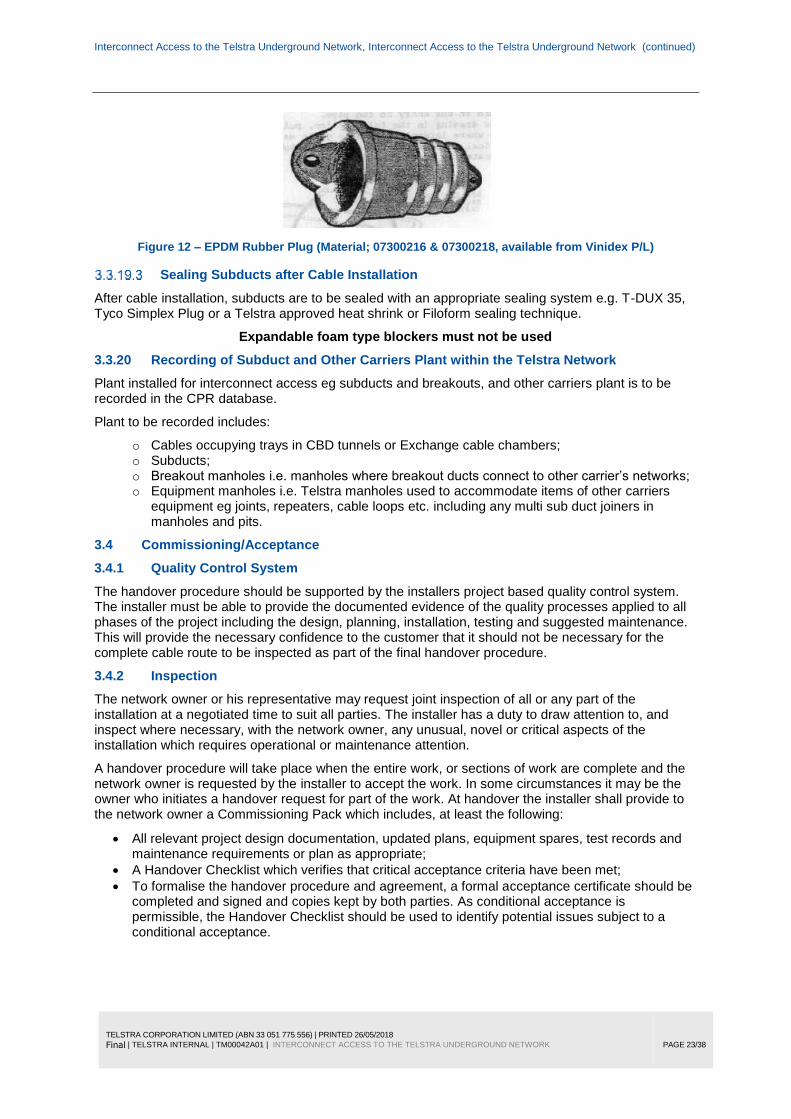
Figure 12 – EPDM Rubber Plug (Material; 07300216 & 07300218, available from Vinidex P/L)
Sealing Subducts after Cable Installation
After cable installation, subducts are to be sealed with an appropriate sealing system e.g. T-DUX 35, Tyco Simplex Plug or a Telstra approved heat shrink or Filoform sealing technique.
Expandable foam type blockers must not be used
3.3.20 Recording of Subduct and Other Carriers Plant within the Telstra Network
Plant installed for interconnect access eg subducts and breakouts, and other carriers plant is to be recorded in the CPR database.
Plant to be recorded includes:
o Cables occupying trays in CBD tunnels or Exchange cable chambers; o Subducts; o Breakout manholes i.e. manholes where breakout ducts connect to other carrier’s networks; o Equipment manholes i.e. Telstra manholes used to accommodate items of other carriers
equipment eg joints, repeaters, cable loops etc. including any multi sub duct joiners in manholes and pits.
3.4 Commissioning/Acceptance
3.4.1 Quality Control System
The handover procedure should be supported by the installers project based quality control system. The installer must be able to provide the documented evidence of the quality processes applied to all phases of the project including the design, planning, installation, testing and suggested maintenance. This will provide the necessary confidence to the customer that it should not be necessary for the complete cable route to be inspected as part of the final handover procedure.
3.4.2 Inspection
The network owner or his representative may request joint inspection of all or any part of the installation at a negotiated time to suit all parties. The installer has a duty to draw attention to, and inspect where necessary, with the network owner, any unusual, novel or critical aspects of the installation which requires operational or maintenance attention.
A handover procedure will take place when the entire work, or sections of work are complete and the network owner is requested by the installer to accept the work. In some circumstances it may be the owner who initiates a handover request for part of the work. At handover the installer shall provide to the network owner a Commissioning Pack which includes, at least the following:
All relevant project design documentation, updated plans, equipment spares, test records and maintenance requirements or plan as appropriate;
A Handover Checklist which verifies that critical acceptance criteria have been met;
To formalise the handover procedure and agreement, a formal acceptance certificate should be completed and signed and copies kept by both parties. As conditional acceptance is permissible, the Handover Checklist should be used to identify potential issues subject to a conditional acceptance.
Interconnect Access to the Telstra Underground Network, Interconnect Access to the Telstra Underground Network (continued)
TELSTRA CORPORATION LIMITED (ABN 33 051 775 556) | PRINTED 26/05/2018
Final | TELSTRA INTERNAL | TM00042A01 | INTERCONNECT ACCESS TO THE TELSTRA UNDERGROUND NETWORK
PAGE 24/38
3.4.3 Handover
Documentation which will be available in the Commissioning Pack at handover of the work will be in accordance with the Handover Checklist, and includes:
Project brief;
Final subduct and break out conduit route plans;
Notice of Intention summary;
Special route maintenance requirements;
Compliance with all Federal, State and Local Government environmental requirement;
Details of significant installation problems encountered.
Details of defective materials and confirmation of prior approvals for nonconforming/nonstandard materials used.
3.5 Recovery
3.5.1 Requirements after Cancellation of a Subduct Lease
Should a Carrier terminate a lease on Telstra subducts it will be required, at the appropriate time;
Remove all cable from the sections of leased Telstra subduct;
Removal all multi sub duct joiners;
Remove all splices and identification tags from the cancelled sections;
Remove all identification tapes from the leased subduct;
Remove all sections of subduct entering the other Carrier’s conduits. Telstra’s subducts are left in situ;
Reseal all redundant breakout points once cable and/or subducts have been removed to prevent gases or liquids transferring between conduit networks. The conduit should be relabelled to indicate that the conduit is owned by the other Carrier;
Remediate manholes and pits damaged by breakouts
Provide drawings to Telstra of the locations of cancelled plant.

Interconnect Access to the Telstra Underground Network, Interconnect Access to the Telstra Underground Network (continued)
TELSTRA CORPORATION LIMITED (ABN 33 051 775 556) | PRINTED 26/05/2018
Final | TELSTRA INTERNAL | TM00042A01 | INTERCONNECT ACCESS TO THE TELSTRA UNDERGROUND NETWORK
PAGE 25/38
4 MATERIAL LIST
The following is a list of the main components that are referred to in this document.
This list is specific to the currently contracted material and may be subject to change:
Table 8 - Material List
Material Description. Material No
PIPE,PE SUB-DUCT 28MM ID/32MM OD 07300107
CONDUIT,PVC 4.5M L 100MM NB 4MM THK 07300207
BUSH,PIPE PVC 100MM 07300102
Multi Subduct Joiner - series ILC41 – Channel Pty Ltd Part 140060
JOINER,SUB-DUCT 32MM DIA COMP 145MM LG 07300283
PLUG,CONDUIT PE 100MM 07300044
Conduit Plug -Pressure Type 438/00024
PLUG,PIPE EPDM 20MM NOM 07300216
PLUG,PIPE EPDM 35MM NOM 07300217
PLUG,PIPE EPDM 50MM NOM 07300218
INSTALLATION TOOL,TDUX SEALING SYSTEM 07300160
DUCT SEALING SYSTEM,WRAPAROUND TDUX45 07300193
DUCT SEALING SYSTEM,WRAPAROUND TDUX60 07300194
DUCT SEALING SYSTEM,WRAPAROUND TDUX100 07300196
CLIP,DUCT TDUX-CL-20 BOX OF 5 07300199
CLIP,DUCT TDUX-CL-60 BOX OF 5 07300227
GAS CYLINDER,CO2 TDUX INFLATION 07300229
BEARER,CABLE MOVABLE 75MM 42600005
BEARER,CABLE MOVABLE 125MM 42600006
BEARER,CABLE MOVABLE 255MM 42600007
BEARER,CABLE MOVABLE 370MM 42600008
BEARER,CABLE MOVABLE 480MM 42600009
Expansion Anchor ½” 089/00011
LUBRICANT,CABLE TYPE A POLYWATER 09100030
ROPE,POLYPROPOLENE BLUE/YELLOW 6MMX400M
67500294

Interconnect Access to the Telstra Underground Network, Interconnect Access to the Telstra Underground Network (continued)
TELSTRA CORPORATION LIMITED (ABN 33 051 775 556) | PRINTED 26/05/2018
Final | TELSTRA INTERNAL | TM00042A01 | INTERCONNECT ACCESS TO THE TELSTRA UNDERGROUND NETWORK
PAGE 26/38
5 REFERENCES
Document number Title
009 959 Material Management Process Overview
013 310 Contract Identification – Contractor Database Requirements
AS/NZS 4130:2009 Polyethylene (PE) pipes for pressure applications
TM00044 Optical Fibre
TM00044-A01 Optical Fibre Winch Compliance
TM00043 Copper Cable
015526A09 Access Network Design Designers Application Guide (New Infrastructure)
010260W02 Pipe and Conduit repair
010265W06 Cable Hauling and Duct Preparation - Cable Recovery from Telstra Network
6 DEFINITIONS
Term Definition
ACIF Australian Communications Industry Forum
AS Australian Standard as published by Standards Australia
Bare Fibre Un subducted Sheathed Fibre Optic cables
Breakout The point in a manhole or pit where another Carrier’s conduit network enters the Telstra conduit network.
Carrier The holder of a communications carrier license under the Telecommunications Act 1997
CFD Construction Finalisation Document
CSP Carriage Service Provider as defined under the Telecommunications Act 1997
CO2 Carbon Dioxide
Conduit A tubular structure, generally circular or oblong in cross-section and manufactured from PVC, asbestos cement, earthenware or galvanised iron, used to carry telecommunications cables in the Telstra underground network. In practice, the term is sometimes used interchangeably with “duct”

Interconnect Access to the Telstra Underground Network, Interconnect Access to the Telstra Underground Network (continued)
TELSTRA CORPORATION LIMITED (ABN 33 051 775 556) | PRINTED 26/05/2018
Final | TELSTRA INTERNAL | TM00042A01 | INTERCONNECT ACCESS TO THE TELSTRA UNDERGROUND NETWORK
PAGE 27/38
Term Definition
DCAF Duct Customer Access Framework
Duct The bore of a conduit. In practice, the term is sometimes used interchangeably with “conduit”
DI Deliverable Item
EPDM Ethyl Propylene Diene Monomer
Exchange Entry Manhole A manhole adjacent to a Telephone exchange where conduits, a tunnel or cable chase enters the Exchange building or cable chamber
ID Internal Diameter
IAL Inaccessible Air Leak
IEN Inter Exchange Network
Joint Join between copper or optical fibre cables
Joint closure The external cover and housing used to protect joints in copper or optical fibre cable
Lead-in The conduit entry into a building emanating from a Telstra manhole or pit
LGA Local Government Agreement
Manhole An underground cable and equipment chamber large enough for a person to work in
Multi Sub Duct Joiner Sub duct jointing enclosure designed to interconnect more than two sub ducts to facilitate easy access to breakout subducts from a straight through Optic fibre run. Commonly known as a “H” joiner
OC Other Carriers
OD Outside Diameter
PSA Product Sourcing Agreement
PE Polyethylene
Pipe A small conduit. In general usage within Telstra, usually under 100mm
Pit An underground cable chamber not large enough for a person to work in
POI Point Of Interconnect
Potholing Verification of cable location by hand digging a hole immediately above the nominal cable alignment to expose the cable.

Interconnect Access to the Telstra Underground Network, Interconnect Access to the Telstra Underground Network (continued)
TELSTRA CORPORATION LIMITED (ABN 33 051 775 556) | PRINTED 26/05/2018
Final | TELSTRA INTERNAL | TM00042A01 | INTERCONNECT ACCESS TO THE TELSTRA UNDERGROUND NETWORK
PAGE 28/38
Term Definition
PVC Poly Vinyl Chloride
Splice Join between fibres of optical fibre cable
Splice closure The external cover and housing used to protect a number of individual splices in optical fibre cable
Subduct Tube placed within a Conduit/Duct for housing cable
Telstra Telstra Corporation Limited
TDUX Raychem Inflatable Duct sealing System
TEBA Telstra Equipment Building Access
TPNI Telstra Physical Network Inventory
WUC Work Under the Contract
7 ATTACHMENTS
Document number Title
Appendix 1
CURRENT PRACTICE FOR BREAKOUT APPROVAL IN COFFIN SHAPED MANHOLES
Appendix 1.1
Current Practice for Breakout Approval in Standard type Manholes (No Turret)
Appendix 1.2 Manholes with a Turret
Appendix 2
T-DUX SOLUTIONS
Appendix 3 HAULING DETAIL SHEET

Interconnect Access to the Telstra Underground Network, Interconnect Access to the Telstra Underground Network (continued)
TELSTRA CORPORATION LIMITED (ABN 33 051 775 556) | PRINTED 26/05/2018
Final | TELSTRA INTERNAL | TM00042A01 | INTERCONNECT ACCESS TO THE TELSTRA UNDERGROUND NETWORK
PAGE 29/38
8 DOCUMENT CONTROL SHEET
Contact for Enquiries and Proposed Changes
If you have any questions regarding this document, or suggestions for improving it, then please contact
Telstra staff contact: Copper & Fibre Technology Solutions
(email: ! Copper & Optic Fibre Technology Solutions)
Contractors contact: Telstra’s Contract Manager
Record of issues
Issue number Issue date Details on the change
1 20 June, 2001 Original Issue
2 05 August, 2003 General revision and update , including:
- Enhanced details for sealing conduit, breakouts and subducts
- Requirement for ‘Hauling Detail Sheet ‘submission
- Enhanced details on joining subduct
- Reference to POI and TEBA
3 14 October, 2009 Addition of the multi subduct joiner Sections 3.2.1.3. & 3.3.6.4.2. AS1159 has now been replaced with AS4130.
4 17 May 2011 Minor update, includes changes to 3.2.2.2
5 14 April 2014 Update to allow bare fibre in building lead ins and MSJ control in Telstra’s non-plastic pits. Sections 3.2.1.1, 3.2.1.3.7 and 3.3.6.4.2
6 23 June 2015 Update to section 3.3.6.4.2 specifying requirement for multi subduct joiners other than approved ILC41.
7 26 June 2018 2 - Scope: wording around Schedule 4 3.1.2 - ACIF C524 Scope and Overview 3.2 - General: Wording to Subduct and inclusion of Bare Fibre cable, Subduct:, Bare Fibre Cable: Created subheading and practice, Checked AS/NZS 4130:2009 as current 3.2.1.3 - Multi Subduct Joiner: Addition of text For H joiner inclusion 3.2.1.4 - Number of sub ducts per Duct: Note included 3.2.3 - Installing Pits for Other Carriers: Changed wording around carriers pits installed over Telstra conduits 3.2.5 - Material Management Process: Changing wording to Materials used are to be Telstra approved, changed from serial/item to material numbers 3.3.1 - Labelling of plant: added more detailed instructions 3.3.2 - Recording of Plant: added more detailed instructions 3.3.3.1 - replaced Dial before you dig to Locating underground assets and removed Dial before you dig 3.3.3.2 - Safe Working Distances removed as it’s covered off in locating underground assets 3.3.4.1 - Removal of Redundant cables: add reference to 010265W06 3.3.5 - Modified Figure 3 3.3.5.1 - Installation in Manholes: wording included shall be negotiated with Telstra on a case by case basis, No conduit is to enter through the section of the manhole, Breakout installation in manholes. 3.3.5.3 - Removed section; Potholing and depth of cover

Interconnect Access to the Telstra Underground Network, Interconnect Access to the Telstra Underground Network (continued)
TELSTRA CORPORATION LIMITED (ABN 33 051 775 556) | PRINTED 26/05/2018
Final | TELSTRA INTERNAL | TM00042A01 | INTERCONNECT ACCESS TO THE TELSTRA UNDERGROUND NETWORK
PAGE 30/38
Issue number Issue date Details on the change
3.3.5.4 - Removed section; Labelling of Breakouts 3.3.5.5 - Removed section; Plugging/Sealing breakout conduits 3.3.6.2 - Changed wording should to shall & Superintendent to Telstra Duct Access Team 3.3.6.3 - Changed Heading from Labelling Subduct to Labelling of Subduct and other Approved Carrier Infrastructure, added Approved Duct study Number and, changed should to shall added (Not to obstruct duct face) and created Note Approved bare fibre cables and any other Approved Carrier Infrastructure shall be labelled using the same specification as above. 3.3.6.4 - Added The Telstra Technical team, and specifications updated. 3.3.6.4.2 - Added The Telstra Technical Team & refer 3.3.6.3 for labelling specifications. 3.3.6.5 - Added ‘nearest’ removed wording manhole walls or to and added Note Where no cable bearers are installed the Contractor/Auditor shall report it to Telstra CNI: 1800 642 882. 3.3.6.6 - Changed wording in last bullet from appropriate to approved and applicable for carrier subduct and breakout conduits only. 3.3.6.7 - Added heading Multi Subduct Interchange with reference to attached instructions 3.3.16.2 Blocked Ducts, Added Note about DCAF 3.3.7.1 Changed should to shall & wording around Polwater lubricants 3.3.9.1 - Sealing Conduits and Breakouts: added Filoform Duct Sealant, remove pressure type plug from figure 10
This publication has been prepared and written by Telstra Corporation Limited (ABN 33 051 775 556), and is copyright. Other than for the purposes of and subject to the conditions prescribed under the Copyright Act, no part of it may in any form or by any means (electronic, mechanical, microcopying, photocopying, recording or otherwise) be reproduced, stored in a retrieval system or transmitted without prior written permission from the document controller. Product or company names are trademarks or registered trademarks of their respective holders. Section 0 Figure 0 Table 0
Note for non-Telstra readers: The contents of this publication are subject to change without notice. All efforts have been made to ensure the accuracy of this publication. Notwithstanding, Telstra Corporation Limited does not assume responsibility for any errors nor for any consequences arising from any errors in this publication.

Interconnect Access to the Telstra Underground Network, Interconnect Access to the Telstra Underground Network (continued)
TELSTRA CORPORATION LIMITED (ABN 33 051 775 556) | PRINTED 26/05/2018
Final | TELSTRA INTERNAL | TM00042A01 | INTERCONNECT ACCESS TO THE TELSTRA UNDERGROUND NETWORK
PAGE 31/38
APPENDIX 1 CURRENT PRACTICE FOR BREAKOUT IN COFFIN SHAPED MANHOLES
TOP
NORTH END ELEVATION
NW CNR NE CNR
**NOT TO SCALE**
NW CNR NE CNR
TOP VIEW
Mandatory requirements: Min 450mm depth of cover and min
from the manhole roof and closest wall
Approved Breakout Location
BREAKOUT NOT PERMITTED Other Carriers Conduits and pits
shall not be installed above or over Telstra alignment
Breakout Not Permitted

Interconnect Access to the Telstra Underground Network, Interconnect Access to the Telstra Underground Network (continued)
TELSTRA CORPORATION LIMITED (ABN 33 051 775 556) | PRINTED 26/05/2018
Final | TELSTRA INTERNAL | TM00042A01 | INTERCONNECT ACCESS TO THE TELSTRA UNDERGROUND NETWORK
PAGE 32/38
A1.1 Current Practice for Breakout in Standard type Manholes (No Turret)
Mandatory Requirements: min 450mm depth of
cover and min 300mm from the manhole roof and
closest wall
BREAKOUT NOT PERMITTED Other Carrier conduits and pits
shall not be installed over Telstra alignment or between existing
conduits
Approved Breakout Location Min 50mm from the manhole floor and min 300mm from the closest
wall
Approved Breakout Locations

Interconnect Access to the Telstra Underground Network, Interconnect Access to the Telstra Underground Network (continued)
TELSTRA CORPORATION LIMITED (ABN 33 051 775 556) | PRINTED 26/05/2018
Final | TELSTRA INTERNAL | TM00042A01 | INTERCONNECT ACCESS TO THE TELSTRA UNDERGROUND NETWORK
PAGE 33/38
A1.2 Manholes with a Turret
Telstra Conduits
SIDE VIEW Not to Scale
Breakout from Turret not permitted
Interconnect Access to the Telstra Underground Network, Interconnect Access to the Telstra Underground Network (continued)
TELSTRA CORPORATION LIMITED (ABN 33 051 775 556) | PRINTED 26/05/2018
Final | TELSTRA INTERNAL | TM00042A01 | INTERCONNECT ACCESS TO THE TELSTRA UNDERGROUND NETWORK
PAGE 34/38
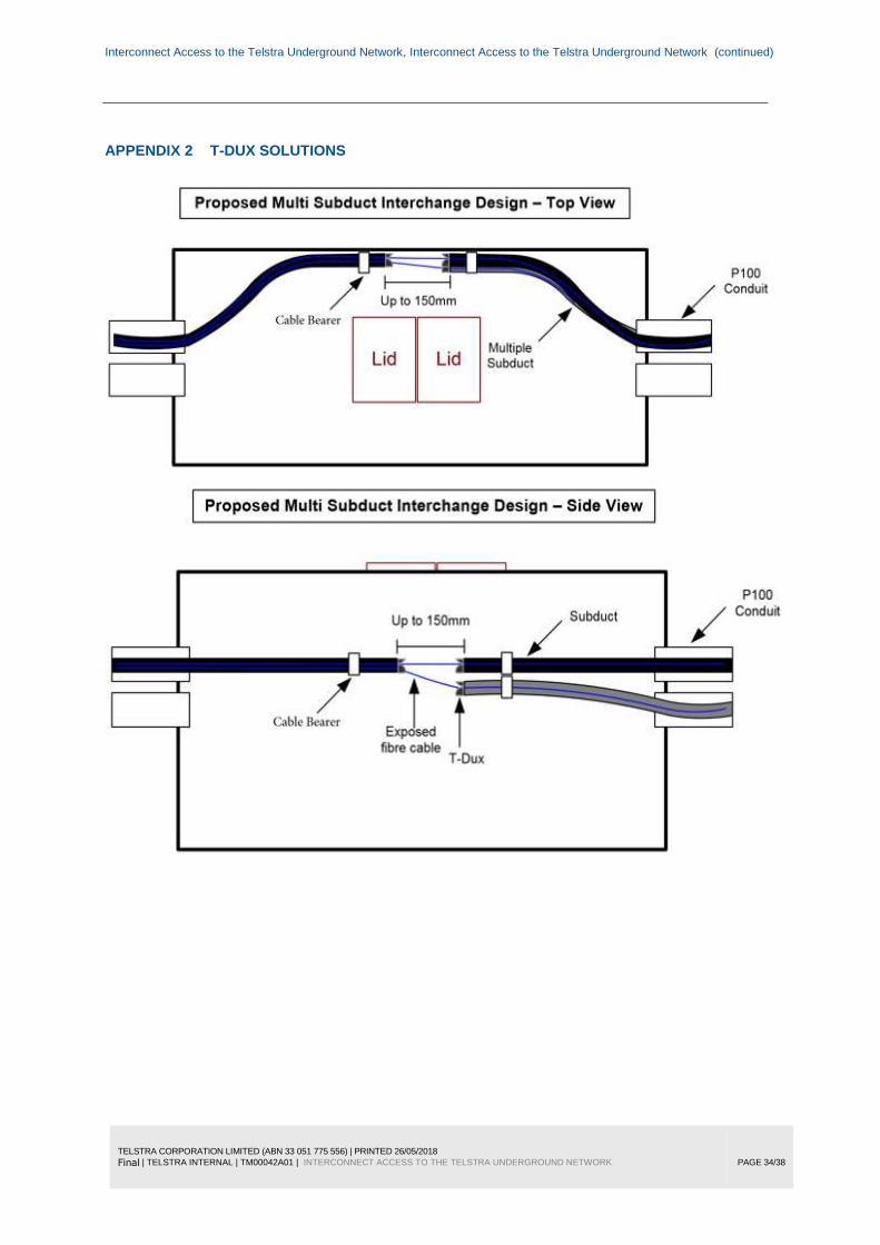
APPENDIX 2 T-DUX SOLUTIONS

Interconnect Access to the Telstra Underground Network, Interconnect Access to the Telstra Underground Network (continued)
TELSTRA CORPORATION LIMITED (ABN 33 051 775 556) | PRINTED 26/05/2018
Final | TELSTRA INTERNAL | TM00042A01 | INTERCONNECT ACCESS TO THE TELSTRA UNDERGROUND NETWORK
PAGE 35/38

Interconnect Access to the Telstra Underground Network, Interconnect Access to the Telstra Underground Network (continued)
TELSTRA CORPORATION LIMITED (ABN 33 051 775 556) | PRINTED 26/05/2018
Final | TELSTRA INTERNAL | TM00042A01 | INTERCONNECT ACCESS TO THE TELSTRA UNDERGROUND NETWORK
PAGE 36/38
Interconnect Access to the Telstra Underground Network, Interconnect Access to the Telstra Underground Network (continued)
TELSTRA CORPORATION LIMITED (ABN 33 051 775 556) | PRINTED 26/05/2018
Final | TELSTRA INTERNAL | TM00042A01 | INTERCONNECT ACCESS TO THE TELSTRA UNDERGROUND NETWORK
PAGE 37/38
Interconnect Access to the Telstra Underground Network, Interconnect Access to the Telstra Underground Network (continued)
TELSTRA CORPORATION LIMITED (ABN 33 051 775 556) | PRINTED 26/05/2018
Final | TELSTRA INTERNAL | TM00042A01 | INTERCONNECT ACCESS TO THE TELSTRA UNDERGROUND NETWORK
PAGE 38/38
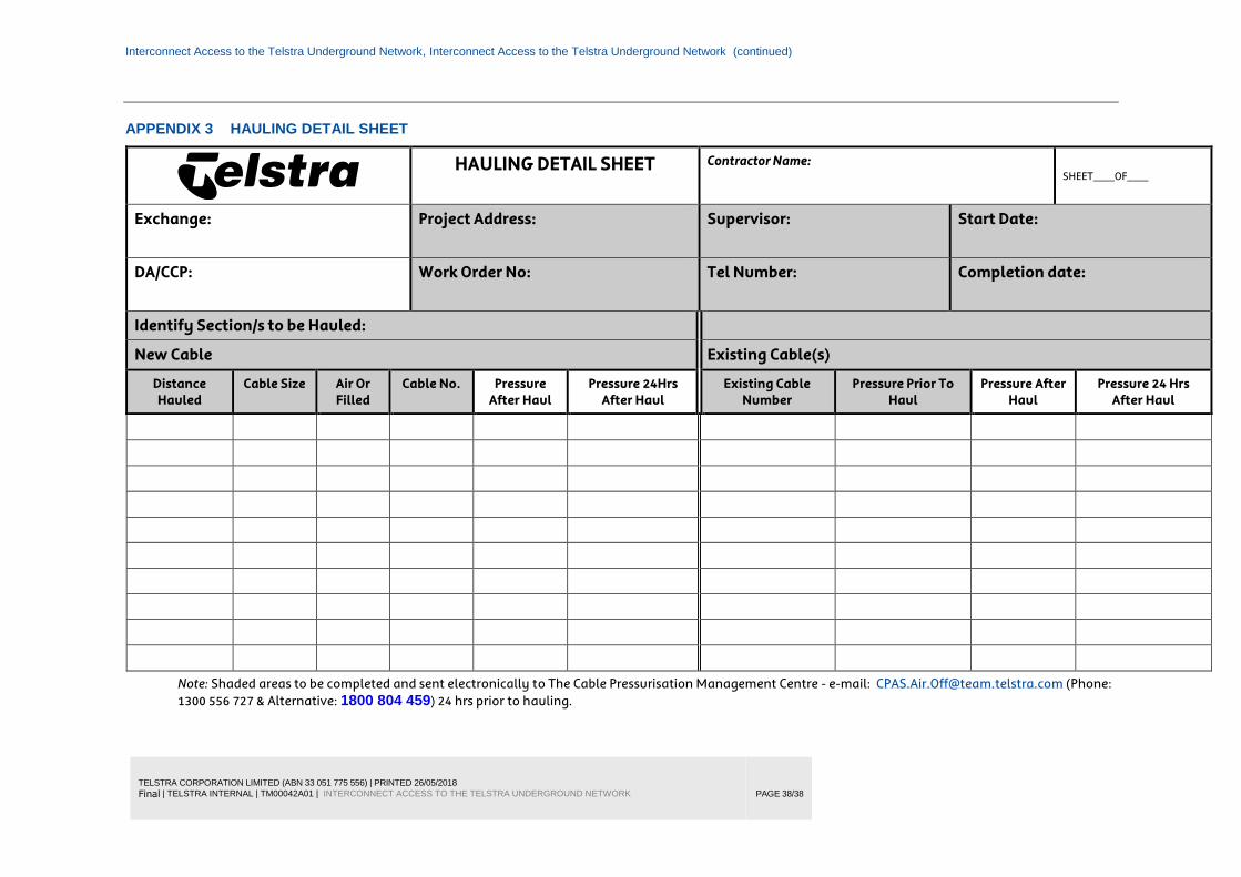
APPENDIX 3 HAULING DETAIL SHEET
HAULING DETAIL SHEET Contractor Name:
SHEET____OF____
Exchange:
Project Address: Supervisor: Start Date:
DA/CCP:
Work Order No: Tel Number: Completion date:
Identify Section/s to be Hauled:
New Cable Existing Cable(s)
Distance
Hauled
Cable Size Air Or
Filled
Cable No. Pressure
After Haul
Pressure 24Hrs
After Haul
Existing Cable
Number
Pressure Prior To
Haul
Pressure After
Haul
Pressure 24 Hrs
After Haul
Note: Shaded areas to be completed and sent electronically to The Cable Pressurisation Management Centre - e-mail: [email protected] (Phone: 1300 556 727 & Alternative: 1800 804 459) 24 hrs prior to hauling.