inverter driven multi-indoor unit heat · pdf fileshock & vibration absorber insulation...
TRANSCRIPT

SELECTION DATA
1. Specifications2. Range of usage & limitations3. Exterior dimensions4. Piping system5. Selection chart6. Electrical wiring
APPLICATION DATA
1. Refrigerant piping2. Electric wiring
INVERTER DRIVEN MULTI-INDOOR UNITHEAT RECOVERY CLIMATE CONTROL SYSTEMINVERTER DRIVEN MULTI-INDOOR UNITHEAT RECOVERY CLIMATE CONTROL SYSTEM
KXRKXR
No.’97·KXR-T-001

(2)OUTDOOR UNIT
(1)INDOOR UNIT
FDC2001HKXRE2,2501HKXRE2
FDR201HKXE2,251HKXE2 FDR401HKXE2,501HKXE2FDR631HKXE2,801HKXE2 FDR1001HKXE2,1251HKXE2
FDUM321HKXE2,401HKXE2 FDUM501HKXE2,631HKXE2,801HKXE2FDUM1001HKXE2,1251HKXE2
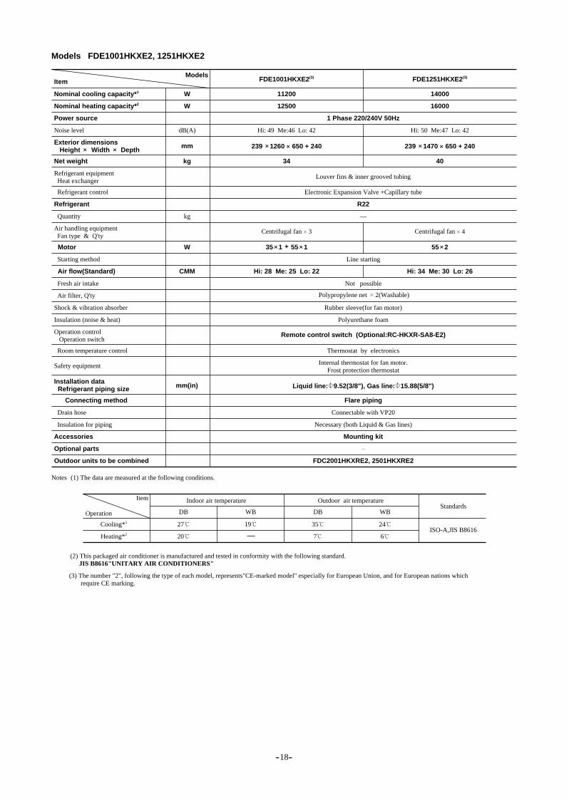
FDE321HKXE2,401HKXE2 FDE501HKXE2,631HKXE2FDE1001HKXE2,1251HKXE2
FDKY251HKXE2,321HKXE2,401HKXE2FDKY501HKXE2,631HKXE2
FDFL251HKXE2,401HKXE2,631HKXE2
specifications
FDT251HKXE2,321HKXE2 FDT401HKXE2,501HKXE2,631HKXE2FDT801HKXE2,1001HKXE2,1251HKXE2FDTW251HKXE2,401HKXE2,501HKXE2 FDTW631HKXE2,801HKXE2FDTW1001HKXE2,1251HKXE2FDTS251HKXE2,321HKXE2 FDTS401HKXE2,631HKXE2
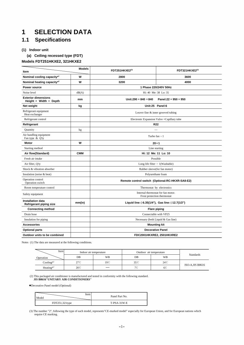
Models FDT251HKXE2, 321HKXE2
(a) Ceiling recessed type (FDT)
(1) Indoor unit
1 SELECTION DATA1.1 Specifications
Item
Nominal cooling capacity*1 W
W
W
CMM
Unit:25 Panel:6
20 1
Hi: 12 Me: 11 Lo: 10
dB(A)
mm Unit:290 840 840 Panel:22 950 950
Nominal heating capacity*2
Power source
Net weight
Refrigerant control
Quantity
Starting method
Fresh air intake
Air filter, Q'ty
Shock & vibration absorber
Insulation (noise & heat)
Room temperature control
Connecting method
Drain hose
Insulation for piping
Accessories
Optional parts
Outdoor units to be combined
Refrigerant
Motor
Air flow(Standard)
Exterior dimensions Height Width Depth
Refrigerant equipment Heat exchanger
Internal thermostat for fan motor.Frost protection thermostat
Air handling equipment Fan type & Q'ty
Operation control Operation switch
Installation data Refrigerant piping size
Noise level
ModelsFDT251HKXE2(3)
2800
3200
FDT321HKXE2(3)
3600
4000
1 Phase 220/240V 50Hz
Electronic Expansion Valve +Capillary tube
Line starting
Possible
Long life filter 1(Washable)
Rubber sleeve(for fan motor)
Polyurethane foam
Flare piping
Connectable with VP25
Necessary (both Liquid & Gas line)
Mounting kit
Decorative Panel
FDC2001HKXRE2, 2501HKXRE2
Thermostat by electronics
Turbo fan 1
Liquid line: 6.35(1/4"), Gas line: 12.7(1/2")mm(in)
Safety equipment
Remote control switch (Optional:RC-HKXR-SA8-E2)
Hi: 40 Me: 38 Lo: 35
Louver fine & inner grooved tubing
(1) The data are measured at the following conditions.Notes
(2) This packaged air conditioner is manufactured and tested in conformity with the following standard. JIS B8616"UNITARY AIR CONDITIONERS"
(3) The number "2", following the type of each model, represents"CE-marked model" especially for European Union, and for European nations which require CE marking.
Decorative Panel model (Optional)
Item
Item
Indoor air temperature Outdoor air temperature Standards
ISO-A,JIS B8616
Operation
Model
FDT251,321type T-PSA-31W-E
Panel Part No.
DB WB DB WB
Cooling*1 27
Heating*2 20
19 35
7
24
6
kg
kg
-- 1 --
—
R22
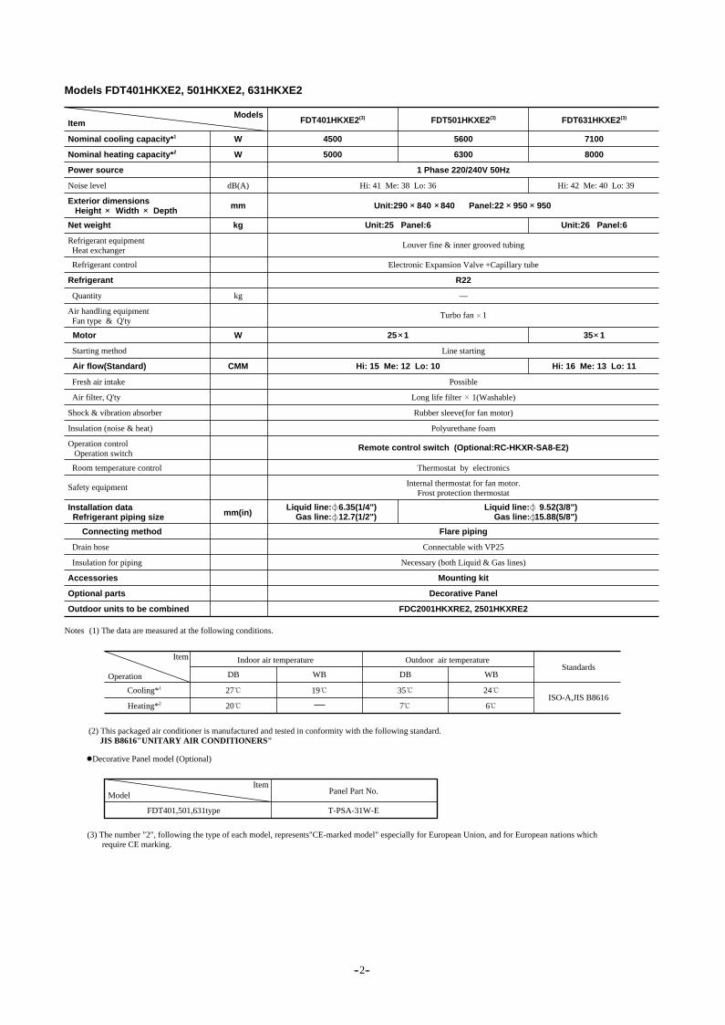
Models FDT401HKXE2, 501HKXE2, 631HKXE2
Item
Nominal cooling capacity*1 W
W
W
CMM
Unit:25 Panel:6
25 1
Unit:26 Panel:6
Hi: 15 Me: 12 Lo: 10 Hi: 16 Me: 13 Lo: 11
35 1
dB(A)
mm Unit:290 840 840 Panel:22 950 950
Nominal heating capacity*2
Power source
Net weight
Refrigerant control
Quantity
Starting method
Fresh air intake
Air filter, Q'ty
Shock & vibration absorber
Insulation (noise & heat)
Room temperature control
Connecting method
Drain hose
Insulation for piping
Accessories
Optional parts
Outdoor units to be combined
Refrigerant
Motor
Air flow(Standard)
Exterior dimensions Height Width Depth
Refrigerant equipment Heat exchanger
Internal thermostat for fan motor.Frost protection thermostat
Air handling equipment Fan type & Q'ty
Operation control Operation switch
Installation data Refrigerant piping size
Noise level
ModelsFDT401HKXE2(3)
4500
FDT501HKXE2(3)
5600
FDT631HKXE2(3)
7100
5000 6300
1 Phase 220/240V 50Hz
Electronic Expansion Valve +Capillary tube
Line starting
Possible
Long life filter 1(Washable)
Rubber sleeve(for fan motor)
Polyurethane foam
Flare piping
Connectable with VP25
Necessary (both Liquid & Gas lines)
Mounting kit
Decorative Panel
FDC2001HKXRE2, 2501HKXRE2
Thermostat by electronics
Turbo fan 1
Liquid line: 6.35(1/4")Gas line: 12.7(1/2")
Liquid line: 9.52(3/8")Gas line: 15.88(5/8")mm(in)
Safety equipment
Remote control switch (Optional:RC-HKXR-SA8-E2)
Hi: 41 Me: 38 Lo: 36
Louver fine & inner grooved tubing
Hi: 42 Me: 40 Lo: 39
8000
(1) The data are measured at the following conditions.Notes
(2) This packaged air conditioner is manufactured and tested in conformity with the following standard. JIS B8616"UNITARY AIR CONDITIONERS"
(3) The number "2", following the type of each model, represents"CE-marked model" especially for European Union, and for European nations which require CE marking.
Decorative Panel model (Optional)
Item
Item
Indoor air temperature Outdoor air temperature Standards
ISO-A,JIS B8616
Operation
Model
FDT401,501,631type T-PSA-31W-E
Panel Part No.
DB WB DB WB
Cooling*1 27
Heating*2 20
19 35
7
24
6
kg
kg —
R22
-- 2--

Models FDT801HKXE2, 1001HKXE2, 1251HKXE2
Item
W
W
W
CMM
kg Unit:26 Panel:6 Unit:31 Panel:6
40 1
Unit:33 Panel:6
Hi: 20 Me: 15 Lo: 12 Hi: 28 Me: 24 Lo: 21 Hi: 30 Me: 26 Lo: 22
130 1
dB(A)
kg
mm
Internal thermostat for fan motor.Frost protection thermostat
ModelsFDT801HKXE2(3)
9000
FDT1001HKXE2(3)
11200
FDT1251HKXE2(3)
14000
10000 12500
1 Phase 220/240V 50Hz
Electronic Expansion Valve +Capillary tube
Line starting
Possible
Long life filter 1(Washable)
Rubber sleeve(for fan motor)
Polyurethane foam
Flare piping
Connectable with VP25
Necessary (both Liquid & Gas lines)
Mounting kit
Decorative Panel
FDC2001HKXRE2, 2501HKXRE2
Thermostat by electronics
Turbo fan 1
Liquid line: 9.52(3/8")Gas line: 15.88(5/8")
Liquid line: 9.52(3/8")Gas line: 19.05(3/4")mm(in)
Remote control switch (Optional:RC-HKXR-SA8-E2)
R22
Hi: 44 Me: 42 Lo: 39 Hi: 52 Me:47 Lo: 42
Louver fins & inner grooved tubing
Hi: 54 Me: 48 Lo: 45
16000
80 1
Item
Item
Indoor air temperature Outdoor air temperature Standards
ISO-A,JIS B8616
Operation
Model
FDT801,1001,1251type T-PSA-31W-E
Panel Part No.
DB WB DB WB
Cooling*1 27
Heating*2 20
19 35
7
24
6
Unit: 290 840 840 Panel:22 950 950
Unit: 340 840 840 Panel:22 950 950
Nominal cooling capacity*1
Nominal heating capacity*2
Power source
Net weight
Quantity
Starting method
Fresh air intake
Air filter, Q'ty
Shock & vibration absorber
Insulation (noise & heat)
Room temperature control
Connecting method
Drain hose
Insulation for piping
Accessories
Optional parts
Outdoor units to be combined
Refrigerant
Motor
Air flow(Standard)
Exterior dimensions Height Width Depth
Refrigerant equipment Heat exchanger
Air handling equipment Fan type & Q'ty
Operation control Operation switch
Installation data Refrigerant piping size
Noise level
Safety equipment
(1) The data are measured at the following conditions.Notes
(2) This packaged air conditioner is manufactured and tested in conformity with the following standard. JIS B8616"UNITARY AIR CONDITIONERS"
(3) The number "2", following the type of each model, represents"CE-marked model" especially for European Union, and for European nations which require CE marking.
Decorative Panel model (Optional)
Refrigerant control
—
-- 3--

Item
W
W
W
CMM
kg Unit:31 Panel:10
Hi: 15 Me: 12 Lo: 9
dB(A)
kg
mm
Internal thermostat for fan motor.Frost protection thermostat
ModelsFDTW251HKXE2(3)
2800
FDTW401HKXE2(3)
4500
FDTW501HKXE2(3)
5600
3200 5000
1 Phase 220/240V 50Hz
Electronic Expansion Valve +Capillary tube
Line starting
Possible
Long life filter 2(Washable)
Rubber sleeve(for fan motor)
Polyurethane foam
Flare piping
Connectable with VP25
Necessary (both Liquid & Gas lines)
Mounting kit
Decorative Panel
FDC2001HKXRE2, 2501HKXRE2
Thermostat by electronics
Centrifugal fan 2
Liquid line: 6.35(1/4")Gas line: 12.7(1/2")
Liquid line: 9.52(3/8")Gas line: 15.88(5/8")mm(in)
Remote control switch (Optional:RC-HKXR-SA8-E2)
Hi: 42 Me:38 Lo: 33
Louver fins & inner grooved tubing
6300
55 1
Item
Item
Indoor air temperature Outdoor air temperature Standards
ISO-A,JIS B8616
Operation
Model Standard type
FDTW251,401,501type TW-PSA-28W-E
Attachment of ceiling material type
TW-PSB-28W-E
Panel Part No.
DB WB DB WB
Cooling*1 27
Heating*2 20
19 35
7
24
6
(b) 2-way outlet ceiling recessed type (FDTW)
Models FDTW251HKXE2, 401HKXE2, 501HKXE2
Unit:380 809 620 Panel:8 1055 680
Nominal cooling capacity*1
Nominal heating capacity*2
Power source
Net weight
Quantity
Starting method
Fresh air intake
Air filter, Q'ty
Shock & vibration absorber
Insulation (noise & heat)
Room temperature control
Connecting method
Drain hose
Insulation for piping
Accessories
Optional parts
Outdoor units to be combined
Refrigerant
Motor
Air flow(Standard)
Exterior dimensions Height Width Depth
Refrigerant equipment Heat exchanger
Operation control Operation switch
Installation data Refrigerant piping size
Noise level
Safety equipment
(1) The data are measured at the following conditions.Notes
(2) This packaged air conditioner is manufactured and tested in conformity with the following standard. JIS B8616"UNITARY AIR CONDITIONERS"
(3) The number "2", following the type of each model, represents"CE-marked model" especially for European Union, and for European nations which require CE marking.
Decorative Panel model (Optional)
Refrigerant control
R22
—
Air handling equipment Fan type & Q'ty
-- 4--

Models FDTW631HKXE2, 801HKXE2
Item
W
W
W
CMM
kg Unit:37 Panel:11
55 1
Hi: 16 Me: 13 Lo: 11 Hi: 19 Me: 16 Lo: 12
80 1
dB(A)
kg
mm Unit:380 1054 620 Panel:8 1300 680
Internal thermostat for fan motor.Frost protection thermostat
ModelsFDTW631HKXE2(3)
7100
FDTW801HKXE2(3)
9000
8000
1 Phase 220/240V 50Hz
Electronic Expansion Valve +Capillay tube
Line starting
Possible
Long life filter 2(Washable)
Rubber sleeve(for fan motor)
Polyurethane foam
Flare piping
Connectable with VP25
Necessary (both Liquid & Gas lines)
Mounting kit
Decorative Panel
FDC2001HKXRE2, 2501HKXRE2
Thermostat by electronics
mm(in)
Remote control switch (Optional:RC-HKXR-SA8-E2)
Hi: 42 Me: 39 Lo: 35
Louver fins & inner grooved tubing
Hi: 42 Me: 40 Lo: 36
10000
Item Indoor air temperature Outdoor air temperature Standards
ISO-A,JIS B8616
Operation DB WB DB WB
Cooling*1 27
Heating*2 20
19 35
7
24
6
Centrifugal fan 2
Liquid line: 9.52(3/8"),Gas line: 15.88(5/8")
Nominal cooling capacity*1
Nominal heating capacity*2
Power source
Net weight
Quantity
Starting method
Fresh air intake
Air filter, Q'ty
Shock & vibration absorber
Insulation (noise & heat)
Room temperature control
Connecting method
Drain hose
Insulation for piping
Accessories
Optional parts
Outdoor units to be combined
Refrigerant
Motor
Air flow(Standard)
Exterior dimensions Height Width Depth
Refrigerant equipment Heat exchanger
Operation control Operation switch
Installation data Refrigerant piping size
Noise level
Safety equipment
(1) The data are measured at the following conditions.Notes
(2) This packaged air conditioner is manufactured and tested in conformity with the following standard. JIS B8616"UNITARY AIR CONDITIONERS"
Decorative Panel model (Optional)
Item
Model Standard type
FDTW631,801type TW-PSA-38W-E
Attachment of ceiling material type
-- 5--
TW-PSB-38W-E
Panel Part No.
(3) The number "2", following the type of each model, represents"CE-marked model" especially for European Union, and for European nations which require CE marking.
Refrigerant control
Air handling equipment Fan type & Q'ty
R22
—
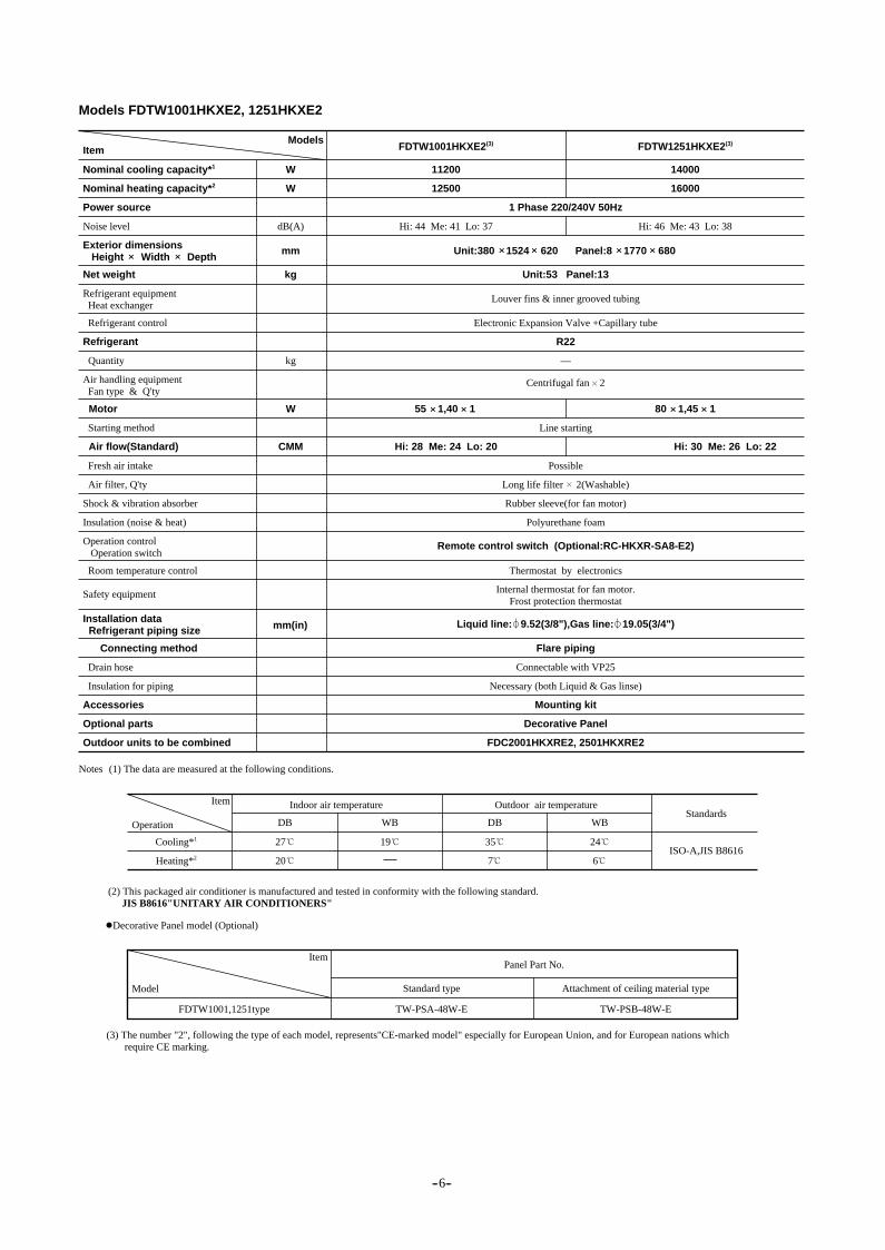
Models FDTW1001HKXE2, 1251HKXE2
Item
W
W
W
CMM
kg Unit:53 Panel:13
55 1,40 1
Hi: 28 Me: 24 Lo: 20 Hi: 30 Me: 26 Lo: 22
dB(A)
kg
mm Unit:380 1524 620 Panel:8 1770 680
Internal thermostat for fan motor.Frost protection thermostat
ModelsFDTW1001HKXE2(3)
11200
FDTW1251HKXE2(3)
14000
12500
1 Phase 220/240V 50Hz
Electronic Expansion Valve +Capillary tube
Line starting
Possible
Long life filter 2(Washable)
Rubber sleeve(for fan motor)
Polyurethane foam
Flare piping
Connectable with VP25
Necessary (both Liquid & Gas linse)
Mounting kit
Decorative Panel
FDC2001HKXRE2, 2501HKXRE2
Thermostat by electronics
mm(in)
Remote control switch (Optional:RC-HKXR-SA8-E2)
Hi: 44 Me: 41 Lo: 37
Louver fins & inner grooved tubing
Hi: 46 Me: 43 Lo: 38
16000
80 1,45 1
Item Indoor air temperature Outdoor air temperature Standards
ISO-A,JIS B8616
Operation DB WB DB WB
Cooling*1 27
Heating*2 20
19 35
7
24
6
Centrifugal fan 2
Liquid line: 9.52(3/8"),Gas line: 19.05(3/4")
Nominal cooling capacity*1
Nominal heating capacity*2
Power source
Net weight
Quantity
Starting method
Fresh air intake
Air filter, Q'ty
Shock & vibration absorber
Insulation (noise & heat)
Room temperature control
Connecting method
Drain hose
Insulation for piping
Accessories
Optional parts
Outdoor units to be combined
Refrigerant
Motor
Air flow(Standard)
Exterior dimensions Height Width Depth
Refrigerant equipment Heat exchanger
Operation control Operation switch
Installation data Refrigerant piping size
Noise level
Safety equipment
(1) The data are measured at the following conditions.Notes
(2) This packaged air conditioner is manufactured and tested in conformity with the following standard. JIS B8616"UNITARY AIR CONDITIONERS"
Decorative Panel model (Optional)
Item
Model Standard type
FDTW1001,1251type TW-PSA-48W-E
Attachment of ceiling material type
-- 6--
TW-PSB-48W-E
Panel Part No.
(3) The number "2", following the type of each model, represents"CE-marked model" especially for European Union, and for European nations which require CE marking.
Refrigerant control
R22
—
Air handling equipment Fan type & Q'ty

Item
W
W
W
CMM
Kg Unit:26 Panel:6
35 1
Hi: 12 Me: 11 Lo: 10
dB(A)
Kg
mm Unit:194 1040 650 Panel:10 1290 770
Internal thermostat for fan motor.Frost protection thermostat
ModelFDTS251HKXE2(3)
2800
FDTS321HKXE2(3)
3600
3200
1 Phase 220/240V 50Hz
Electronic Expansion Valve +Capillary tube
Line starting
Possible
Long life filter 1(Washable)
Rubber sleeve(for fan motor)
Polyurethane foam
Flare piping
Connectable with VP25
Necessary (both Liquid & Gas lines)
Mounting kit
Decorative Panel
FDC2001HKXRE2, 2501HKXRE2
Thermostat by electronics
mm(in)
Remote control switch (Optional:RC-HKXR-SA8-E2)
Hi: 40 Me: 39 Lo: 38
Louver fine & inner grooved tubing
4000
Item
Item
Indoor air temperature Outdoor air temperature Standards
ISO-A,JIS B8616
Operation
Model
FDTS251,321 type
-- 7--
TS-PSA-26W-E
Panel Part No.With Auto Swing
DB WB DB WB
Cooling*1 27
Heating*2 20
19 35
7
24
6
Centrifugal fan 2
Liquid line: 6.35(1/4"),Gas line: 12.7(1/2")
(c) 1-way outlet ceiling recessed type (FDTS)
Models FDTS251HKXE2, 321HKXE2
Nominal cooling capacity*1
Nominal heating capacity*2
Power source
Net weight
Quantity
Starting method
Fresh air intake
Air filter, Q'ty
Shock & vibration absorber
Insulation (noise & heat)
Room temperature control
Connecting method
Drain hose
Insulation for piping
Accessories
Optional parts
Outdoor units to be combined
Refrigerant
Motor
Air flow(Standard)
Exterior dimensions Height Width Depth
Refrigerant equipment Heat exchanger
Operation control Operation switch
Installation data Refrigerant piping size
Noise level
Safety equipment
(1) The data are measured at the following conditions.Notes
(2) This packaged air conditioner is manufactured and tested in conformity with the following standard. JIS B8616"UNITARY AIR CONDITIONERS"
(3) The number "2", following the type of each model, represents"CE-marked model" especially for European Union, and for Europern nations which require CE marking.
Decorative Panel model (Optional)
Refrigerant control
R22
—
Air handling equipment Fan type & Q'ty

Models FDTS401HKXE2, 631HKXE2
Item
W
W
W
CMM
kg Unit:26 Panel:6 Unit:30 Panel:7
40 1
Hi: 14 Me: 12 Lo: 10 Hi: 18 Me: 15 Lo: 12
25 2
dB(A)
kg
mm
Internal thermostat for fan motor.Frost protection thermostat
ModelFDTS401HKXE2(3)
4500
FDTS631HKXE2(3)
7100
5000
1 Phase 220/240V 50Hz
Electronic Expansion Valve +Capillary tube
Line starting
Possible
Long life filter 1(Washable)
Rubber sleeve(for fan motor)
Polyurethane foam
Flare piping
Connectable with VP25
Necessary (both Liquid & Gas line)
Mounting kit
Decorative Panel
FDC2001HKXRE2, 2501HKXRE2
Thermostat by electronics
mm(in)
Remote control switch (Optional:RC-HKXR-SA8-E2)
Hi: 43 Me: 40 Lo: 38
Louver fins & inner grooved tubing
Hi: 44 Me: 40 Lo: 38
8000
Item Indoor air temperature Outdoor air temperature Standards
ISO-A,JIS B8616
Operation DB WB DB WB
Cooling*1 27
Heating*2 20
19 35
7
24
6
Centrifugal fan 4Centrifugal fan 2
Nominal cooling capacity*1
Nominal heating capacity*2
Power source
Net weight
Quantity
Starting method
Fresh air intake
Air filter, Q'ty
Shock & vibration absorber
Insulation (noise & heat)
Room temperature control
Connecting method
Drain hose
Insulation for piping
Accessories
Optional parts
Outdoor units to be combined
Refrigerant
Motor
Air flow(Standard)
Exterior dimensions Height Width Depth
Refrigerant equipment Heat exchanger
Operation control Operation switch
Installation data Refrigerant piping size
Noise level
Safety equipment
(1) The data are measured at the following conditions.Notes
(2) This packaged air conditioner is manufactured and tested in conformity with the following standard. JIS B8616"UNITARY AIR CONDITIONERS"
Decorative Panel model (Optional)
Item
Model With Auto Swing
FDTS401 type
FDTS631 type
TS-PSA-26W-E
TS-PSA-36W-E
Panel Part No.
(3) The number "2", following the type of each model, represents"CE-marked model" especially for European Union, and for European nations which require CE marking.
Unit:194 1040 650 Panel:10 1290 770
Unit:194 1300 650 Panel:10 1500 790
Liquid line: 6.35(1/4")Gas line: 12.7(1/2")
Liquid line: 9.52(3/8")Gas line: 15.88(5/8")
Refrigerant control
R22
—
Air handling equipment Fan type & Q'ty
-- 8--

-- 9--
(d) Cassetteria type (FDR)
Models FDR201HKXE2, 251HKXE2
Item
Nominal cooling capacity*1
Panel model (Option)
Air inlet panel Silent panel
R-PNLS-26W-E R-PNLC-26W-E R-PNLS-26W-E R-PNLC-26W-E
Canvas panel Canvas panelSilent panel
W
W
W
CMM
kg
mmAq Standard:4.5, Hi speed:8.5
Unit:30Panel:7
Unit:30Panel:5
Unit:30Panel:7
Unit:30Panel:5
40 1
Hi: 10 Me: 9 Lo: 8 Hi: 12 Me: 11 Lo: 10
50 1
dB(A)
kg
mm Unit:355 750 635 Panel:10 1040 750
Nominal heating capacity*2
Power source
Net weight
Refrigerant control
Quantity
Starting method
Fresh air intake
Air filter Q'ty
Shock & vibration absorber
Insulation (noise & heat)
Room temperature control
Connecting method
Drain hose
Insulation for piping
Accessories
Optional parts
Outdoor units to be combined
Refrigerant
Motor
Air flow(Standard)
Exterior dimensions Height Width Depth
Refrigerant equipment Heat exchanger
Internal thermostat for fan motor.Frost protection thermostat
Air handling equipment Fan type&Q'ty
Available static pressure ( at Me)
Operation control Operation switch
Installation data Refrigerant piping size
Noise level
ModelsFDR201HKXE2(4)
2200
FDR251HKXE2(4)
2800
2500
1 Phase 220/240V 50Hz
Electronic Expansion Valve +Capillary tube
Line starting
Side or back
Long life filter 1(Washable)
Rubber sleeve(for fan motor)
Polyurethane foam
Flare piping
Connectable with VP25
Necessary (both Liquid & Gas lines)
Mounting kit
Silent panel, Canvas panel, Canvas duct
FDC2001HKXRE2, 2501HKXRE2
Thermostat by electronics
—
Liquid line: 6.35(1/4"),Gas line: 12.7(1/2")mm(in)
Safety equipment
Remote control switch (Optional:RC-HKXR-SN8-E2)
R22
Hi: 41 Me: 39 Lo: 36 Hi: 42 Me: 40 Lo: 37 Hi: 42 Me: 40 Lo: 37 Hi: 43 Me: 41 Lo: 38
Louver fins &inner grooved tubing
3200
Unit:355 750 635 Panel:10 864 585
Unit:355 750 635 Panel:10 864 585
Unit:355 750 635 Panel:10 1040 750
(1)The data are measured at the following conditions.Notes
(2)This packaged air conditioner is manufactured and tested in conformity with the following standard. JIS B8616"UNITARY AIR CONDITIONERS"
(3)Canvas panel is used in combination with follwing canvas duct Canvas duct: HA01503
(4)The number "2"f,ollowing the type of each model,represents"CE-marked model"especially for European Union, and for European nations which require CE marking.
(5)Add the canvas duct lenght to the unit height for the canvas type.
Item Indoor air temperature Outdoor air temperature Standards
ISO-A,JIS B8616
Operation DB WB DB WB
Cooling*1 27
Heating*2 20
19 35
7
24
6
Centrifugal fan 2

-- 10--
Models FDR401HKXE2, 501HKXE2
Item
Nominal cooling capacity*1
Panel model (Option)
Air inlet panel Silent panel
R-PNLS-26W-E R-PNLC-26W-E R-PNLS-26W-E R-PNLC-26W-E
Canvas panel Canvas panelSilent panel
W
W
W
CMM
kg
mmAq Standard:5.0, Hi speed:8.5
Unit:30Panel:7
Unit:30Panel:5
Unit:35Panel:7
Unit:35Panel:5
Hi: 14 Me: 12 Lo: 11
55 1
dB(A)
kg
mm Unit:355 750 635 Panel:10 1040 750
Nominal heating capacity*2
Power source
Net weight
Refrigerant control
Quantity
Starting method
Fresh air intake
Air filter Q'ty
Shock & vibration absorber
Insulation (noise & heat)
Room temperature control
Connecting method
Drain hose
Insulation for piping
Accessories
Optional parts
Outdoor units to be combined
Refrigerant
Motor
Air flow(Standard)
Exterior dimensions Height Width Depth
Refrigerant equipment Heat exchanger
Internal thermostat for fan motor.Frost protection thermostat
Air handling equipment Fan type&Q'ty
Available static pressure ( at Me)
Operation control Operation switch
Installation data Refrigerant piping size
Noise level
ModelsFDR401HKXE2(4)
4500
FDR501HKXE2(4)
5600
5000
1 Phase 220/240V 50Hz
Electronic Expansion Valve +Capillary tube
Line starting
Side or back
Long life filter 1(Washable)
Rubber sleeve(for fan motor)
Polyurethane foam
Flare piping
Connectable with VP25
Necessary (both Liquid & Gas lines)
Mounting kit
Silent panel, Canvas panel, Canvas duct
FDC2001HKXRE2, 2501HKXRE2
Thermostat by electronics
—
Liquid line: 6.35(1/4")Gas line: 12.7(1/2")
mm(in)
Safety equipment
Remote control switch (Optional:RC-HKXR-SN8-E2)
R22
Hi: 43 Me: 40 Lo: 37 Hi: 44 Me: 41 Lo: 38 Hi:43 Me: 40 Lo: 37 Hi: 44 Me: 41 Lo: 38
Louver fins & inner grooved tubing
6300
Unit:355 750 635 Panel:10 864 585
Unit:355 750 635 Panel:10 864 585
Unit:355 750 635 Panel:10 1040 750
Liquid line: 9.52(3/8")Gas line: 15.88(5/8")
(1)The data are measured at the following conditions.Notes
(2)This packaged air conditioner is manufactured and tested in conformity with the following standard. JIS B8616"UNITARY AIR CONDITIONERS"
(3)Canvas panel is used in combination with follwing canvas duct Canvas duct: HA01503
(4)The number "2",following the type of each model,represents"CE-marked model"especially for European Union, and for Europearn nations which require CE marking.
(5)Add the canvas duct lenght to the unit height for the canvas type.
Item Indoor air temperature Outdoor air temperature Standards
ISO-A,JIS B8616
Operation DB WB DB WB
Cooling*1 27
Heating*2 20
19 35
7
24
6
Centrifugal fan 2

-- 11--
Models FDR631HKXE2, 801HKXE2
Item
Nominal cooling capacity*1
Panel model (Option)
Air inlet panel Silent panel
R-PNLS-36W-E R-PNLC-36W-E R-PNLS-36W-E R-PNLC-36W-E
Canvas panel Canvas panelSilent panel
W
W
W
CMM
kg
mmAp Standard:4.5, Hi speed:8.0
Unit:35Panel:8
Unit:35Panel:6
Unit:50Panel:8
Unit:50Panel:6
Hi: 18 Me: 16 Lo: 14 Hi: 20 Me: 18 Lo: 15
90 1
dB(A)
Kg
mm Unit:355 950 635 Panel:10 1240 750
Nominal heating capacity*2
Power source
Net weight
Refrigerant control
Quantity
Starting method
Fresh air intake
Air filter Q'ty
Shock & vibration absorber
Insulation (noise & heat)
Room temperature control
Connecting method
Drain hose
Insulation for piping
Accessories
Optional parts
Outdoor units to be combined
Refrigerant
Motor
Air flow(Standard)
Exterior dimensions Height Width Depth
Refrigerant equipment Heat exchanger
Internal thermostat for fan motor.Frost protection thermostat
Air handling equipment Fan type&Q'ty
Available static pressure ( at Me)
Operation control Operation switch
Installation data Refrigerant piping size
Noise level
ModelsFDR631HKXE2(4)
7100
FDR801HKXE2(4)
9000
8000
1 Phase 220/240V 50Hz
Electronic Expansion Valve +Capillary tube
Line starting
Side or back
Long life filter 1(Washable)
Rubber sleeve(for fan motor)
Polyurethane foam
Flare piping
Connectable with VP25
Necessary (both Liquid & Gas lines)
Mounting kit
Silent panel, Canvas panel, Canvas duct
FDC2001HKXRE2, 2501HKXRE2
Thermostat by electronics
—
mm(in)
Safety equipment
Remote control switch (Optional:RC-HKXR-SN8-E2)
R22
Hi: 43 Me: 40 Lo: 37 Hi: 44 Me: 41 Lo: 38 Hi: 44 Me: 40 Lo: 37 Hi: 44 Me: 41 Lo: 38
Louver fins & inner grooved tubing
10000
Unit:355 950 635 Panel:10 1064 585
Unit:355 950 635 Panel:10 1040 585
Unit:355 950 635 Panel:10 1240 750
100 1
(1)The data are measured at the following conditions.Notes
(2)This packaged air conditioner is manufactured and tested in conformity with the following standard. JIS B8616"UNITARY AIR CONDITIONERS"
(3)Canvas panel is used in combination with follwing canvas duct Canvas duct:
(4)The number "2",following the type of each model,represents"CE-marked model"especially for European Union, and for European nations which require CE marking.
(5)Add the canvas duct lenght to the unit height for the canvas type.
Item Indoor air temperature Outdoor air temperature Standards
ISO-A,JIS B8616
Operation DB WB DB WB
Cooling*1 27
Heating*2 20
19 35
7
24
6
Centrifugal fan 2
Liquid line: 9.52(3/8"),Gas line: 15.88(5/8")
FDR801 type: HA01503FDR1001 type: HA01484

-- 12--
Models FDR1001HKXE2, 1251HKXE2
Item
Nominal cooling capacity*1
Panel model (Option)
Air inlet panel Silent panel
R-PNLS-46W-E R-PNLC-46W-E R-PNLS-46W-E R-PNLC-46W-E
Canvas panel Canvas panelSilent panel
W
W
W
CMM
kg
mmAq Standard:5.0, Hi speed:8.0
Unit:50Panel:9
Unit:50Panel:7
Unit:52Panel:9
Unit:52Panel:7
Hi: 28 Me: 25 Lo: 22 Hi: 34 Me: 31 Lo: 27
45 1,
dB(A)
kg
mm Unit:406 1370 635 Panel:10 1660 750
Nominal heating capacity*2
Power source
Net weight
Refrigerant control
Quantity
Starting method
Fresh air intake
Air filter Q'ty
Shock & vibration absorber
Insulation (noise & heat)
Room temperature control
Connecting method
Drain hose
Insulation for piping
Accessories
Optional parts
Outdoor units to be combined
Refrigerant
Motor
Air flow(Standard)
Exterior dimensions Height Width Depth
Refrigerant equipment Heat exchanger
Internal thermostat for fan motor.Frost protection thermostat
Air handling equipment Fan type&Q'ty
Available static pressure ( at Me)
Operation control Operation switch
Installation data Refrigerant piping size
Noise level
ModelsFDR1001HKXE2(4)
11200
FDR1251HKXE2(4)
14000
12500
1 Phase 220/240V 50Hz
Electronic Expansion Valve +Capillary tube
Line starting
Side or back
Long life filter 2(Washable)
Rubber sleeve(for fan motor)
Polyurethane foam
Flare piping
Connectable with VP25
Necessary (both Liquid & Gas lines)
Mounting kit
Silent panel, Canvas panel, Canvas duct
FDC2001HKXRE2, 2501HKXRE2
Thermostat by electronics
—
mm(in)
Safety equipment
Remote control switch (Optional:RC-HKXR-SN8-E2)
R22
Hi: 45 Me: 42 Lo: 38 Hi: 46 Me: 43 Lo: 39 Hi: 46 Me: 43 Lo: 39 Hi: 47 Me: 44 Lo: 40
Louver fins & inner grooved tubing
16000
Unit:406 1370 635 Panel:10 1484 585
Unit:406 1370 635 Panel:10 1484 585
Unit:406 1370 635 Panel:10 1660 750
90 1 50 1, 100 1
(1)The data are measured at the following conditions.Notes
(2)This packaged air conditioner is manufactured and tested in conformity with the following standard. JIS B8616"UNITARY AIR CONDITIONERS"
(3)Canvas panel is used in combination with follwing canvas duct Canvas duct: HA01484
(4)The number "2",following the type of each model,represents"CE-marked model"especially for European Union, and for European nations which require CE marking.
(5)Add the canvas duct lenght to the unit height for the canvas type.
Item Indoor air temperature Outdoor air temperature Standards
ISO-A,JIS B8616
Operation DB WB DB WB
Cooling*1 27
Heating*2 20
19 35
7
24
6
Centrifugal fan 3
Liquid line: 9.52(3/8"),Gas line: 19.05(3/4")

Item
W
W
W
CMM
kg 34
50 1
Hi: 12 Me: 11 Lo: 10 Hi: 14 Me: 12 Lo: 11
55 1
dB(A)
kg
mm 299 750 635
Internal thermostat for fan motor.Frost protection thermostat
ModelsFDUM321HKXE2(3)
3600
FDUM401HKXE2(3)
4500
4000
1 Phase 220/240V 50Hz
Electronic Expansion Valve +Capillary tube
Line starting
Side
Rubber sleeve(for fan motor)
Polyurethane foam
Flare piping
Connectable with VP25
Necessary (both Liquid & Gas lines)
Mounting kit
FDC2001HKXRE2, 2501HKXRE2
Thermostat by electronics
—
mm(in)
Remote control switch (Optional:RC-HKXR-SN8-E2)
R22
Hi: 34 Me: 32 Lo: 29
Louver fins & inner grooved tubing
Hi: 35 Me: 32 Lo: 29
5000
Item Indoor air temperature Outdoor air temperature Standards
ISO-A,JIS B8616
Operation DB WB DB WB
Cooling*1 27
Heating*2 20
19 35
7
24
6
Centrifugal fan 2
Liquid line: 6.35(1/4"),Gas line: 12.7(1/2")
Nominal cooling capacity*1
Nominal heating capacity*2
Power source
Net weight
Quantity
Starting method
Fresh air intake
Air filter, Q'ty
Shock & vibration absorber
Insulation (noise & heat)
Room temperature control
Connecting method
Drain hose
Insulation for piping
Accessories
Optional parts
Outdoor units to be combined
Refrigerant
Motor
Air flow(Standard)
Exterior dimensions Height Width Depth
Refrigerant equipment Heat exchanger
Operation control Operation switch
Installation data Refrigerant piping size
Noise level
Safety equipment
(1) The data are measured at the following conditions.Notes
(2) This packaged air conditioner is manufactured and tested in conformity with the following standard. JIS B8616"UNITARY AIR CONDITIONERS"
(3) The number "2", following the type of each model, represents"CE-marked model" especially for European Union, and for European nations which require CE marking.
Refrigerant control
Air handling equipment Fan type & Q'ty
(e) Satellite ducted type (FDUM)
Models FDUM321HKXE2, 401HKXE2
mmAqAvailable static pressure ( at Me)
Standard:5, Hi speed:8.5
_
_
-- 13--

Item
W
W
W
CMM
kg 4034
55 1
Hi: 14 Me: 12 Lo: 11 Hi: 18 Me: 16 Lo: 14 Hi: 20 Me: 18 Lo: 15
dB(A)
kg
mm
Internal thermostat for fan motor.Frost protection thermostat
ModelsFDUM501HKXE2(3) FDUM631HKXE2(3)
5600
FDUM801HKXE2(3)
7100
6300
1 Phase 220/240V 50Hz
Electronic Expansion Valve +Capillary tube
Line starting
Side
Rubber sleeve(for fan motor)
Polyurethane foam
Flare piping
Connectable with VP25
Necessary (both Liquid & Gas lines)
Mounting kit
FDC2001HKXRE2, 2501HKXRE2
Thermostat by electronics
—
mm(in)
Remote control switch (Optional:RC-HKXR-SN8-E2)
R22
Hi: 35 Me: 32 Lo: 29
Louver fins & inner grooved tubing
Hi: 36 Me: 33 Lo: 30Hi: 35 Me: 32 Lo: 29
8000
9000
10000
90 1 100 1
299 750 635 299 950 635
Item Indoor air temperature Outdoor air temperature Standards
ISO-A,JIS B8616
Operation DB WB DB WB
Cooling*1 27
Heating*2 20
19 35
7
24
6
Centrifugal fan 2
Liquid line: 9.52(3/8"),Gas line: 15.88(5/8")
Nominal cooling capacity*1
Nominal heating capacity*2
Power source
Net weight
Quantity
Starting method
Fresh air intake
Air filter, Q'ty
Shock & vibration absorber
Insulation (noise & heat)
Room temperature control
Connecting method
Drain hose
Insulation for piping
Accessories
Optional parts
Outdoor units to be combined
Refrigerant
Motor
Air flow(Standard)
Exterior dimensions Height Width Depth
Refrigerant equipment Heat exchanger
Operation control Operation switch
Installation data Refrigerant piping size
Noise level
Safety equipment
(1) The data are measured at the following conditions.Notes
(2) This packaged air conditioner is manufactured and tested in conformity with the following standard. JIS B8616"UNITARY AIR CONDITIONERS"
(3) The number "2", following the type of each model, represents"CE-marked model" especially for European Union, and for European nations which require CE marking.
Refrigerant control
Air handling equipment Fan type & Q'ty
Models FDUM501HKXE2, 631HKXE2, 801HKXE2
mmAqAvailable static pressure ( at Me)
Standard:5, Hi speed:8.5
_
_
-- 14--
Item
W
W
W
CMM
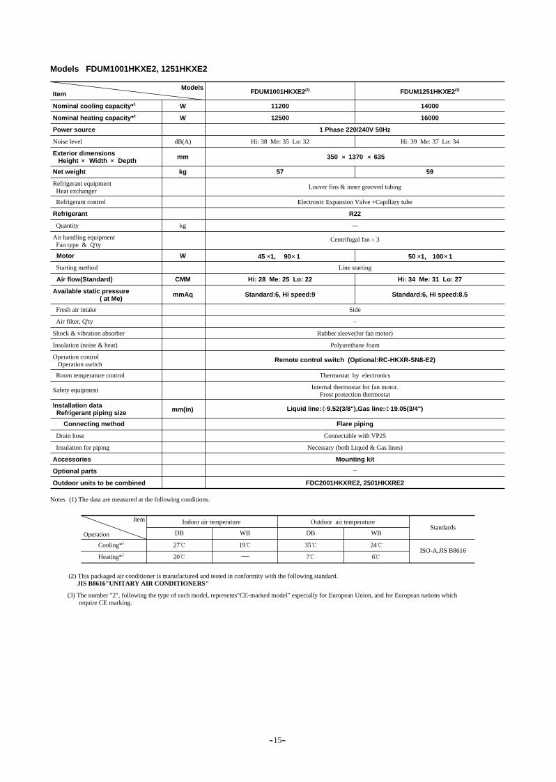
kg 5957
45 1,
Hi: 28 Me: 25 Lo: 22 Hi: 34 Me: 31 Lo: 27
90 1
dB(A)
kg
mm 350 1370 635
Internal thermostat for fan motor.Frost protection thermostat
ModelsFDUM1001HKXE2(3)
11200
FDUM1251HKXE2(3)
14000
12500
1 Phase 220/240V 50Hz
Electronic Expansion Valve +Capillary tube
Line starting
Side
Rubber sleeve(for fan motor)
Polyurethane foam
Flare piping
Connectable with VP25
Necessary (both Liquid & Gas lines)
Mounting kit
FDC2001HKXRE2, 2501HKXRE2
Thermostat by electronics
—
mm(in)
Remote control switch (Optional:RC-HKXR-SN8-E2)
R22
Hi: 38 Me: 35 Lo: 32
Louver fins & inner grooved tubing
Hi: 39 Me: 37 Lo: 34
16000
50 1, 100 1
Item Indoor air temperature Outdoor air temperature Standards
ISO-A,JIS B8616
Operation DB WB DB WB
Cooling*1 27
Heating*2 20
19 35
7
24
6
Centrifugal fan 3
Liquid line: 9.52(3/8"),Gas line: 19.05(3/4")
Nominal cooling capacity*1
Nominal heating capacity*2
Power source
Net weight
Quantity
Starting method
Fresh air intake
Air filter, Q'ty
Shock & vibration absorber
Insulation (noise & heat)
Room temperature control
Connecting method
Drain hose
Insulation for piping
Accessories
Optional parts
Outdoor units to be combined
Refrigerant
Motor
Air flow(Standard)
Exterior dimensions Height Width Depth
Refrigerant equipment Heat exchanger
Operation control Operation switch
Installation data Refrigerant piping size
Noise level
Safety equipment
(1) The data are measured at the following conditions.Notes
(2) This packaged air conditioner is manufactured and tested in conformity with the following standard. JIS B8616"UNITARY AIR CONDITIONERS"
(3) The number "2", following the type of each model, represents"CE-marked model" especially for European Union, and for European nations which require CE marking.
Refrigerant control
Air handling equipment Fan type & Q'ty
Models FDUM1001HKXE2, 1251HKXE2
mmAqAvailable static pressure ( at Me)
Standard:6, Hi speed:9 Standard:6, Hi speed:8.5
_
_
-- 15--

Item
W
W
W
CMM
kg 22
Hi: 14 Me: 12 Lo: 10
dB(A)
kg
mm
Internal thermostat for fan motor.Frost protection thermostat
ModelsFDE321HKXE2(3)
3600
FDE401HKXE2(3)
4500
4000
1 Phase 220/240V 50Hz
Electronic Expansion Valve + Capillary tube
Line starting
Not possible
Polypropylene net 2(Washable)
Rubber sleeve(for fan motor)
Polyurethane foam
Flare piping
Connectable with VP20
Necessary (both Liquid & Gas lines)
Mounting kit_
FDC2001HKXRE2, 2501HKXRE2
Thermostat by electronics
—
Centrifugal fan 2
Liquid line: 6.35(1/4"), Gas line: 12.7(1/2")mm(in)
Remote control switch (Optional:RC-HKXR-SA8-E2)
R22
Hi: 43 Me:40 Lo: 38
Louver fins & inner grooved tubing
5000
40 1
(f) Ceiling suspension type (FDE)
Models FDE321HKXE2, 401HKXE2
184 1000 650 + 240
Nominal cooling capacity*1
Nominal heating capacity*2
Power source
Net weight
Quantity
Starting method
Fresh air intake
Air filter, Q'ty
Shock & vibration absorber
Insulation (noise & heat)
Room temperature control
Connecting method
Drain hose
Insulation for piping
Accessories
Optional parts
Outdoor units to be combined
Refrigerant
Motor
Air flow(Standard)
Exterior dimensions Height Width Depth
Refrigerant equipment Heat exchanger
Operation control Operation switch
Installation data Refrigerant piping size
Noise level
Safety equipment
Refrigerant control
Air handling equipment Fan type & Q'ty
Item Indoor air temperature Outdoor air temperature Standards
ISO-A,JIS B8616
Operation DB WB DB WB
Cooling*1 27
Heating*2 20
19 35
7
24
6
(1) The data are measured at the following conditions.Notes
(2) This packaged air conditioner is manufactured and tested in conformity with the following standard. JIS B8616"UNITARY AIR CONDITIONERS"
(3) The number "2", following the type of each model, represents"CE-marked model" especially for European Union, and for European nations which require CE marking.
-- 16--

Item
W
W
W
CMM
kg 22
Hi: 14 Me: 12 Lo: 10 Hi: 18 Me: 15 Lo: 12
dB(A)
kg
mm
Internal thermostat for fan motor.Frost protection thermostat
ModelsFDE501HKXE2(3)
5600
FDE631HKXE2(3)
7100
6300
1 Phase 220/240V 50Hz
Electronic Expansion Valve + Capillary tube
Line starting
Not possible
Rubber sleeve(for fan motor)
Polyurethane foam
Flare piping
Connectable with VP20
Necessary (both Liquid & Gas lines)
Mounting kit_
FDC2001HKXRE2, 2501HKXRE2
Thermostat by electronics
—
Centrifugal fan 2
Liquid line: 9.52(3/8"), Gas line: 15.88(5/8")mm(in)
Remote control switch (Optional:RC-HKXR-SA8-E2)
R22
Hi: 43 Me:40 Lo: 38
Louver fins & inner grooved tubing
8000
40 1
Centrifugal fan 4
25 2
Models FDE501HKXE2, 631HKXE2
184 1000 650 + 240
27
Hi: 44 Me:40 Lo: 38
184 1260 650 + 240
Nominal cooling capacity*1
Nominal heating capacity*2
Power source
Net weight
Quantity
Starting method
Fresh air intake
Air filter, Q'ty
Shock & vibration absorber
Insulation (noise & heat)
Room temperature control
Connecting method
Drain hose
Insulation for piping
Accessories
Optional parts
Outdoor units to be combined
Refrigerant
Motor
Air flow(Standard)
Exterior dimensions Height Width Depth
Refrigerant equipment Heat exchanger
Operation control Operation switch
Installation data Refrigerant piping size
Noise level
Safety equipment
Refrigerant control
Air handling equipment Fan type & Q'ty
Item Indoor air temperature Outdoor air temperature Standards
ISO-A,JIS B8616
Operation DB WB DB WB
Cooling*1 27
Heating*2 20
19 35
7
24
6
(1) The data are measured at the following conditions.Notes
(2) This packaged air conditioner is manufactured and tested in conformity with the following standard. JIS B8616"UNITARY AIR CONDITIONERS"
(3) The number "2", following the type of each model, represents"CE-marked model" especially for European Union, and for European nations which require CE marking.
Polypropylene net 2(Washable)
-- 17--
Item
W
W
W
CMM
kg 34
Hi: 28 Me: 25 Lo: 22 Hi: 34 Me: 30 Lo: 26
dB(A)
kg
mm
Internal thermostat for fan motor.Frost protection thermostat
ModelsFDE1001HKXE2(3)
11200
FDE1251HKXE2(3)
14000
12500
1 Phase 220/240V 50Hz
Electronic Expansion Valve +Capillary tube
Line starting
Not possible
Rubber sleeve(for fan motor)
Polyurethane foam
Flare piping
Connectable with VP20
Necessary (both Liquid & Gas lines)
Mounting kit_
FDC2001HKXRE2, 2501HKXRE2
Thermostat by electronics
—
Centrifugal fan 3
Liquid line: 9.52(3/8"), Gas line: 15.88(5/8")mm(in)
Remote control switch (Optional:RC-HKXR-SA8-E2)
R22
Hi: 49 Me:46 Lo: 42
Louver fins & inner grooved tubing
16000
35 1 55 1+
Centrifugal fan 4
55 2
Models FDE1001HKXE2, 1251HKXE2
239 1260 650 + 240
40
Hi: 50 Me:47 Lo: 42
239 1470 650 + 240
Nominal cooling capacity*1
Nominal heating capacity*2
Power source
Net weight
Quantity
Starting method
Fresh air intake
Air filter, Q'ty
Shock & vibration absorber
Insulation (noise & heat)
Room temperature control
Connecting method
Drain hose
Insulation for piping
Accessories
Optional parts
Outdoor units to be combined
Refrigerant
Motor
Air flow(Standard)
Exterior dimensions Height Width Depth
Refrigerant equipment Heat exchanger
Operation control Operation switch
Installation data Refrigerant piping size
Noise level
Safety equipment
Refrigerant control
Air handling equipment Fan type & Q'ty
Item Indoor air temperature Outdoor air temperature Standards
ISO-A,JIS B8616
Operation DB WB DB WB
Cooling*1 27
Heating*2 20
19 35
7
24
6
(1) The data are measured at the following conditions.Notes
(2) This packaged air conditioner is manufactured and tested in conformity with the following standard. JIS B8616"UNITARY AIR CONDITIONERS"
(3) The number "2", following the type of each model, represents"CE-marked model" especially for European Union, and for European nations which require CE marking.
Polypropylene net 2(Washable)
-- 18--

Item
W
W
W
CMM
kg 19
Hi: 10 Me: 9 Lo: 8 Hi: 11.5 Me: 10 Lo: 8
dB(A)
kg
mm
Internal thermostat for fan motor.Frost protection thermostat
ModelsFDKY251HKXE2(3)
2800
FDKY401HKXE2(3)
4500
3200
FDKY321HKXE2(3)
3600
4000
1 Phase 220/240V 50Hz
Electronic Expansion Valve + Capillary tube
Line starting
Not possible
Rubber sleeve(for fan motor)
Polyurethane foam
Flare piping
Connectable with I.D. 16mm
Necessary (both Liquid & Gas lines)
—
Mounting kit
FDC2001HKXRE2, 2501HKXRE2
Thermostat by electronics
—
Centrifugal fan 2
Liquid line: 6.35(1/4"), Gas line: 12.7(1/2")mm(in)
Remote control switch (Optional:RC-HKXR-SA8-E2)
R22
Hi: 42 Me:40 Lo: 37 Hi: 44 Me:41 Lo: 37
Louver fins & inner grooved tubing
5000
30 1 35 1
(g) Wall mounted type (FDKY)
Models FDKY251HKXE2, 321HKXE2, 401HKXE2
375 930 194
Nominal cooling capacity*1
Nominal heating capacity*2
Power source
Net weight
Quantity
Starting method
Fresh air intake
Air filter, Q'ty
Shock & vibration absorber
Insulation (noise & heat)
Room temperature control
Connecting method
Drain hose
Insulation for piping
Accessories
Optional parts
Outdoor units to be combined
Refrigerant
Motor
Air flow(Standard)
Exterior dimensions Height Width Depth
Refrigerant equipment Heat exchanger
Operation control Operation switch
Installation data Refrigerant piping size
Noise level
Safety equipment
Refrigerant control
Air handling equipment Fan type & Q'ty
Item Indoor air temperature Outdoor air temperature Standards
ISO-A,JIS B8616
Operation DB WB DB WB
Cooling*1 27
Heating*2 20
19 35
7
24
6
(1) The data are measured at the following conditions.Notes
(2) This packaged air conditioner is manufactured and tested in conformity with the following standard. JIS B8616"UNITARY AIR CONDITIONERS"
(3) The number "2", following the type of each model, represents"CE-marked model" especially for European Union, and for European nations which require CE marking.
Polypropylene net 2(Washable)
-- 19--

Item
W
W
W
CMM
kg 20 22
Hi: 17 Me: 15 Lo: 13 Hi: 21 Me: 18 Lo: 15
dB(A)
kg
mm
Internal thermostat for fan motor.Frost protection thermostat
ModelFDKY501HKXE2(3)
5600
6300
FDKY631HKXE2(3)
7100
8000
1 Phase 220/240V 50Hz
Electronic Expansion Valve + Capillary tube
Line starting
Not possible
Rubber sleeve(for fan motor)
Polyurethane foam
Flare piping
Connectable with I.D. 16mm
Necessary (both Liquid & Gas lines)
Mounting kit_
FDC2001HKXRE2, 2501HKXRE2
Thermostat by electronics
—
Tangential fan 2
Liquid line: 9.52(3/8"), Gas line: 15.88(5/8")mm(in)
Remote control switch (Optional:RC-HKXR-SA8-E2)
R22
Hi: 46 Me:43 Lo: 39 Hi: 47 Me:44 Lo: 40
Louver fins & inner grooved tubing
40 1 45 1
Tangential fan 1
Models FDKY501HKXE2, 631HKXE2
375 1148 194 375 1436 194
Nominal cooling capacity*1
Nominal heating capacity*2
Power source
Net weight
Quantity
Starting method
Fresh air intake
Air filter, Q'ty
Shock & vibration absorber
Insulation (noise & heat)
Room temperature control
Connecting method
Drain hose
Insulation for piping
Accessories
Optional parts
Outdoor units to be combined
Refrigerant
Motor
Air flow(Standard)
Exterior dimensions Height Width Depth
Refrigerant equipment Heat exchanger
Operation control Operation switch
Installation data Refrigerant piping size
Noise level
Safety equipment
Refrigerant control
Air handling equipment Fan type & Q'ty
Item Indoor air temperature Outdoor air temperature Standards
ISO-A,JIS B8616
Operation DB WB DB WB
Cooling*1 27
Heating*2 20
19 35
7
24
6
(1) The data are measured at the following conditions.Notes
(2) This packaged air conditioner is manufactured and tested in conformity with the following standard. JIS B8616"UNITARY AIR CONDITIONERS"
(3) The number "2", following the type of each model, represents"CE-marked model" especially for European Union, and for European nations which require CE marking.
Polypropylene net 2(Washable)
-- 20--

Item
W
W
W
CMM
kg 32
Hi: 14 Me: 12 Lo: 10 Hi: 18 Me: 15 Lo: 12Hi: 12 Me: 11 Lo: 10
dB(A)
kg
mm
Internal thermostat for fan motor.Frost protection thermostat
ModelFDFL251HKXE2(3)
2800
FDFL631HKXE2(3)
7100
3200
FDFL401HKXE2(3)
4500
5000
1 Phase 220/240V 50Hz
Electronic Expansion Valve + Capillary tube
Line starting
Not possible
Rubber sleeve(for fan motor)
Polyurethane foam
Flare piping
Connectable with VP20
Necessary (both Liquid & Gas lines)
Mounting kit_
FDC2001HKXRE2, 2501HKXRE2
Thermostat by electronics
—
Centrifugal fan 2
Liquid line: 6.35(1/4"), Gas line: 12.7(1/2")mm(in)
Remote control switch (Optional:RC-HKXR-SN8-E2)
R22
Hi: 41 Me:38 Lo: 36 Hi: 43 Me:41 Lo: 40
Louver fins & inner grooved tubing
8000
40 130 1
(h) Floor standing type (FDFL)
Models FDFL251HKXE2, 401HKXE2, 631HKXE2
630 1196 225
40
630 1481 225
Nominal cooling capacity*1
Nominal heating capacity*2
Power source
Net weight
Quantity
Starting method
Fresh air intake
Air filter, Q'ty
Shock & vibration absorber
Insulation (noise & heat)
Room temperature control
Connecting method
Drain hose
Insulation for piping
Accessories
Optional parts
Outdoor units to be combined
Refrigerant
Motor
Air flow(Standard)
Exterior dimensions Height Width Depth
Refrigerant equipment Heat exchanger
Operation control Operation switch
Installation data Refrigerant piping size
Noise level
Safety equipment
Refrigerant control
Air handling equipment Fan type & Q'ty
Item Indoor air temperature Outdoor air temperature Standards
ISO-A,JIS B8616
Operation DB WB DB WB
Cooling*1 27
Heating*2 20
19 35
7
24
6
(1) The data are measured at the following conditions.Notes
(2) This packaged air conditioner is manufactured and tested in conformity with the following standard. JIS B8616"UNITARY AIR CONDITIONERS"
(3) The number "2", following the type of each model, represents"CE-marked model" especially for European Union, and for European nations which require CE marking.
Liquid line: 9.52(3/8")Gas line: 15.88(5/8")
Polypropylene net 2(Washable)
-- 21--

Item
W
W
kg
kW
RS5555EAV31 1 RS5570EAV31 1
270
dB(A)
%
W
kg
W
CMM 175
mm(in)
mm
ModelsFDC2501HKXE2(3)
28000
FDC2001HKXE2(3)
22400
25000
3 Phase 380/415V 50Hz
Direct start
Direct start
Brazing
Discharge gas side connection piping (for operation valve and back direction connections),intake gas side connection piping (for operation valve and back direction connections)
FDT251, 321, 401, 501, 631, 801, 1001, 1251typeFDTW251, 401, 501, 631, 801, 1001, 1251typeFDTS251, 321, 401, 631typeFDR201, 251, 401, 501, 631, 801, 1001, 1251typeFDUM321, 401, 501, 631, 801, 1001, 1251typeFDE321, 401, 501, 631, 1001, 1251typeFDKY251, 321, 401, 501, 631typeFDFL251, 401, 631type
Hole for drain( 20 6pcs)
Necessary (both Liquid &Gas lines)
60
31500
(2) Outdoor unit
Models FDC2001HKXRE2, 2501HKXRE2
280
2.5 (BARREL FREEZE 32SAM)
11
100 ~ 22.0
40
5.5
R22
7.5
1700 1350 600
Nominal cooling capacity*1
Power source
Nominal heating capacity*2
Net weight
Capacity control
Crankcase heater
Heat exchanger
Refrigerant control
Refrigerant
Quantity
Refrigerant oil
Defrost control
Starting method
Exterior dimensions Height Width Depth
Refrigerant equipment compressor type & Q' ty
Noise level
Motor
(1) The cooling and heating capabilities imply the values when the indoor unit of rated capacity is connected under the condition specified in JIS-B8616.
Flow divide controller part No. list
(2) The refrigerant quantity in the connecting pipe is not included Charge it additionally at the site.
(4) When an individual flow divide controller is used a pipe part set is required.
Notes
(3) The number "2", following the type of each model, represents"CE-marked model" especially for European Union, and for European nations which require CE marking.
Type
Individual flow divide controller HPFD01R-E
FDC2001,2501
Part No. Type
For 3 pipes (for horizontal division)
For 3 pipes (for vertical division)
DIS-IKXR3-E
DIS-VIKXR3-E
FDC2001,2501
Part No.
Air handling equipment Fan type & Q'ty
Motor
Starting method
Air flow(Standard)
Shock & vibration absorber Rubber mount (for compressor)
Compressor overheat protection, overeurrent protection, power transformer overheatingprotection, abnormal high pressure protection
Safety equipment
Connecting method
Drain
Insulation for piping
Accessories
Indoor units to be combined
Installation data Refrigerant piping size
Expansion Valve +Capillary tube
MC controlled De-Icer
Louver fines & inner grooved tubing
Centrifugal fan 2
100 2
Liquid line: 12.7(1/2")Gas line: 25.4(1")
Liquid line: 12.7(1/2")Gas line: 28.58(11/8")
-- 22--

SystemFDC2001HKXRE2 FDC2501HKXRE2
Refer to the capacity characterstics.
1 to 8 units
1.2 Range of usage & limitations
Item
Indoor intake air temperature(Upper, lower limits)
Outdoor air temperature(Upper, lower limits)
Single direction piping lenght Indoor unit MAX 100m
MAX 30m
6 min or more(from stop to stop or from start to start)
3 min or more
Within 10% of rated voltage
MAX 50m
MAX 20m
MAX 15m
Dew point temperature 28 or less, relative humidity 80% or less
Pipining length after first division
Number of connected units
Total capacity 11000 to 29200w 13200 to 37100w
When above outdoor unit
When below outdoor unit
Indoor unitsthat can beused incombination
Difference inheight betweenindoor and outdoorunits
Difference in height between indoor units
Indoor unit atmosphere (behind ceiling)temperrature and humidity
1 cycle time
Stop time
Voltage fluctuation
Interval unbalance
Compressorstop/start frequency
Power sourcevoltage Voltage drop during start
+_
+_
Within 3% of rated voltage +_
Within 15% of rated voltage
-- 23--
Indoor unit
Individual flow divide controller
First branch
Between the outdoor unit and first branch (main piping): Max 70m (actual length)Between the first branch and each indoor unit : Max 30m (each indoor unit) (actual length) The indoor unit and individual flow divide controller positions should be within the range of the reach of the connections of the wires that come with the individual flow divide contorollerNote 1:
Allowable length of refrigerant piping, Height difference between indoor and outdoor unit
Outdoor unit
50m
30mMax
30mMax
(Max 70m )
15m
Max
(Out
door
uni
t is
low
er :
20m
)
(Lowest indoor unit)
Individual flow divaidecontroller
(Highest indoor unit)

(2)Remote controller (optional parts)
(1)INDOOR UNIT
(4)OUTDOOR UNIT
FDT251HKXE2,321HKXE2,401HKXE2,501HKXE2,631HKXE2,801HKXE2FDT1001HKXE2,1251HKXE2
FDC2001HKXRE2,2501HKXRE2
FDTW251HKXE2,401HKXE2,501HKXE2 FDTW631HKXE2,801HKXE2FDTW1001HKXE2,1251HKXE2
FDTS251HKXE2,321HKXE2,401HKXE2 FDTS631HKXE2
FDR201HKXE2 (Silent Panel) (Canvas Panel) FDR251HKXE2,401HKXE2,501HKXE2 (Silent Panel) (Canvas Panel)FDR631HKXE2,801HKXE2 (Silent Panel) (Canvas Panel) FDR1001HKXE2,1251HKXE2 (Silent Panel) (Canvas Panel)
FDUM321HKXE2,401HKXE2,501HKXE2 FDUM631HKXE2,801HKXE2FDUM1001HKXE2,1251HKXE2
FDE321HKXE2,401HKXE2,501HKXE2 FDE631HKXE2FDE1001HKXE2 FDE1251HKXE2
FDKY251HKXE2,321HKXE2,401HKXE2 FDKY501HKXE2FDKY631HKXE2 FDFL251HKXE2,401HKXE2,631HKXE2
Exterior dimentions
(3)Individual flow divide controller(Optional Part)

1.3 Exterior dimensions(1) Indoor unit
(a) Ceiling recessed type (FDT)
Models FDT251HKXE2,321HKXE2,401HKXE2,501HKXE2,631HKXE2,801HKXE2
Unit : mm
Decoraitve Panel
VIEW A
VIEW DVIEW C
DETAIL B
Space for installation and service
295~
325
-- 24--

Models FDT1001HKXE2,1251HKXE2
Unit : mm
Decoraitve Panel
VIEW A
VIEW DVIEW C
DETAIL B
Space for installation and service
295~
325
-- 25--

(b) 2-way outlet ceiling recessed type (FDTW)
Models FDTW251HKXE2,401HKXE2,501HKXE2
Unit : mm
VIEW A
Space for installation and service
Decoraitve Panel
295~325
-- 26--

Models FDTW631HKXE2,801HKXE2
Unit : mm
VIEW A
Space for installation and service
295~325
Decoraitve Panel
-- 27--
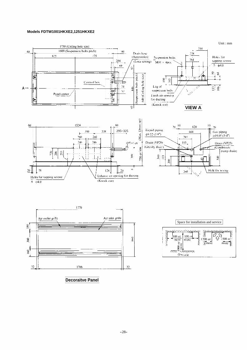
Models FDTW1001HKXE2,1251HKXE2
Unit : mm
VIEW A
Space for installation and service
295~325
Decoraitve Panel
-- 28--

(c) 1-Way outlet ceiling recessed type (FDTS)
Models FDTS251HKXE2,321HKXE2,401HKXE2
Unit : mm
VIEW A
Space for installation and service
295~325
Decoraitve PanelVIEW B
VIEW C
-- 29--

Model FDTS631HKXE2
Unit : mm
VIEW A
Space for installation and service
295~325
Decoraitve Panel
VIEW B
VIEW C
-- 30--

(d) Cassetteria type (FDR)
Model FDR201HKXE2
Unit : mm
VIEW C
295~325
VIEW B
VIEW A
Silent Panel (Model: R-PNLS-26W-E)
Space for installation and service
-- 31--

Model FDR201HKXE2
Unit : mm
VIEW C
295~325
VIEW B VIEW A
Space for installation and service
Canvas Panel (Model: R-PNLC-26W-E)
-- 32--

Models FDR251HKXE2, 401HKXE2, 501HKXE2
Silent Panel (Model: R-PNLS-26W-E)
-- 33--
Unit : mm
VIEW C
VIEW B
VIEW A
Space for installation and service

Models FDR251HKXE2,401HKXE2,501HKXE2Unit : mm
VIEW C
295~325
VIEW B
VIEW A
Space for installation and service
Canvas Panel (Model: R-PNLC-26W-E)
-- 34--

Models FDR631HKXE2,801HKXE2
Unit : mm
VIEW C
295~325
VIEW B
VIEW A
Space for installation and service
Silent Panel (Model: R-PNLS-36W-E)
-- 35--

Models FDR631HKXE2,801HKXE2
Unit : mm
VIEW C
295~325
VIEW B
VIEW ASpace for installation and service
Canvas Panel (Model: R-PNLC-36W-E)
-- 36--

Models FDR1001HKXE2,1251HKXE2
Unit : mm
VIEW C
295~325
VIEW B
VIEW A
Space for installation and service
Silent Panel (Model: R-PNLS-46W-E)
-- 37--

Models FDR1001HKXE2,1251HKXE2
Unit : mm
VIEW C
295~325
VIEW B
VIEW ASpace for installation and service
Canvas Panel (Model: R-PNLC-46W-E)
-- 38--

(e) Satellite ducted type (FDUM)
Models FDUM321HKXE2,401HKXE2,501HKXE2
Unit : mm
VIEW A
295~325
VIEW B
Space for installation and service
-- 39--

Models FDUM631HKXE2,801HKXE2
Unit : mm
VIEW A
295~325
VIEW B
Space for installation and service
-- 40--

Models FDUM1001HKXE2,1251HKXE2Unit : mm
VIEW A
295~325
VIEW B
Space for installation and service
-- 41--

(f) Ceiling suspension type (FDE)
Models FDE321HKXE2,401HKXE2,501HKXE2
Model FDE631HKXE2
Unit : mm
Space for installation and service
Space for installation and service
Note (1) The slope of drain piping inside the unit is able to take incline of 10 mm
-- 42--

Model FDE1001HKXE2
Model FDE1251HKXE2
Unit : mm
Space for installation and service
Space for installation and service
Note (1) The slope of drain piping inside the unit is able to take incline of 10 mm.
Note (1) The slope of drain piping inside the unit is able to take incline of 10 mm.
Unit : mm
-- 43--

(g) Wall mounted type (FDKY)
Models FDKY251HKXE2,321HKXE2,401HKXE2
Model FDKY501HKXE2
Unit : mm
Space for installation and service
Space for installation and service
Unit : mm
Detail of mounting plate
Detail of mounting plate
VIEW A (Rear side)
VIEW A (Rear side)
-- 44--

Model FDKY631HKXE2
(h) Floor standing type (FDFL)
Models FDFL251HKXE2,401HKXE2,631HKXE2 Value in ( ) indicates 631 type.
Unit : mm
Space for installation and service
Detail of mounting plate
VIEW A (Rear side)
-- 45--

(2) Remote controller (Optional parts)
JIS box to be used
JIS C8336 Outlet box-Middle size, square-
deep type and JIS C8336 switch cover-for
2pcs. With paint margin.
Standard length of remote controller cable : 15m for All Models.
Notes (1) Allowable length of remote controller
cable: 600 m
Standard Within 0.3 mm2 × Within 100 m 0.5 mm2 × Within 200 m 0.75 mm2 × Within 300 m 1.25 mm2 × Within 400 m 2 mm2 × Within 600 m
Allowable rang of wire thickness and length
AUTOFANCOOL
FILTERRESETHEATDRY
CHECK
TIMERMODE
FAN SPEED
TIME
ROOMTEMP
FAN COOL DRY
REMOTE
PROGRAM
HIGH MED LO
°CMORELESS
HEAT AUTOHOT KEEP
CENTER
FAN SPEED
TIMER
°C
ONOFF
SET TEMP.
H
AUTO SWING OFF
ON
AUTOFANCOOL
FILTERRESETHEATDRY
CHECK
TIMERMODE
FAN SPEED
TIME
ROOMTEMP
FAN COOL DRY
REMOTE
PROGRAM
HIGH MED LO
°CMORELESS
HEAT AUTOHOT KEEP
CENTER
FAN SPEED
TIMER
°C
ONOFF
SET TEMP.
H
AUTO SWING OFF
ON
RC-HKXR-SA8-E2:3 fan speed RC-HKXR-SN8-E2:3 fan speed
-- 46--

(3) Individual flow divide controller (Optional Part)
HPFD01R-E
-- 47--

(4) Ou
tdo
or u
nit
FD
C2001H
KX
RE
2, 2501HK
XR
E2
(φ12.7 (1/2") flare)
200: with φ25.4 (1") pipe250: with φ28.58 (1 1/8") pipe
-- 48--

1.4 Pip
ing
System
FD
C2001H
KX
RE
2, 2501HK
XR
E2
(2) Preset point of protective devices 63H1 : 3.0 open, 2.4 closed MPaG (30 open, 24 closed kg/cm2G) [for protective] 63H2 : 2.55 open, 2.15 closed MPaG (25.5 open, 21.5 closed kg/cm2G) [for high-pressure control (Hz decrease)] 63H3 : 2.2 open, 1.9 closed MPaG (22 open, 19 closed kg/cm2G) [for high-pressure decrease control] 63H4 : 1.5 open, 1.75 closed MPaG (15 open, 17.5 closed kg/cm2G) [for high-pressure increase control] 63L : 0.2 open, 0.28 closed MPaG (2.0 open, 2.8 closed kg/cm2G) [for low-pressure increase control] DPR1,2 : 1.8 open MPaG (18 open kg/cm2G) DPR3 : 2.4 open MPaG (24 open kg/cm2G)
(3) Function of thermistor ThO-A : For low outside air cooling/heating, frost removal control ThO-R : For frost removal control ThO-D : For Discharge piping temperature control ThO-C : For dome bottom temperature control ThI-R : For fan control during heating For frost prevention during cooling
(4) Flow divide controller solenoid valve action chart
SVH
SVC
Closed
Closed
PowersupplyOFF
Closed
Open
Powersupply
ON
Closed
Open
Cool-ing(1)
Open
Closed
Heat-ing(1)
Closed
Open
Blower
Closed
Open
Detrost
Note (1) Including for pauses, stops, and errors.
-- 49--

Correction of outdoor unit capacity according to capacity of indoor unit to be operated simultaneously
FDC2001HKXRE2,2501HKXRE2
(2)Sensible heat capacity
(1)Indoor unit capacity (a) (b) (c)
FDT251HKXE2,321HKXE2,401HKXE2,501HKXE2FDT631HKXE2,801HKXE21001HKXE2,1251HKXE2FDTW251HKXE2,401HKXE2,501HKXE2,631HKXE2FDTW801HKXE2,1001HKXE2,1251HKXE2FDTS251HKXE2,321HKXE2,401HKXE2,631HKXE2
FDR201HKXE2,251HKXE2,401HKXE2,501HKXE2FDR631HKXE2,801HKXE2,1001HKXE2,1251HKXE2
FDUM321HKXE2,401HKXE2,501HKXE2,631HKXE2FDUM801HKXE2,1001HKXE2,1251HKXE2
FDE321HKXE2,401HKXE2,501HKXE2,631HKXE2FDE1001HKXE2,1251HKXE2 FDFL251HKXE2,401HKXE2
FDKY501HKXE2,631HKXE2FDFL631HKXE2 FDKY251HKXE2,321HKXE2,401HKXE2
Selection chart

1.5 Selection chart(1) Indoor unit capacity
Correct the cooling and heating capacity in accordance with the conditions as follows. The net cooling and heating capacity can be,
obtained in the following way.
Net capacity = Capacity shown on specifications × Correction factors as follows.
(a) Coefficient of cooling and heating capacity in relation to temperatures
(b) Correction of cooling and heating capacity in relation to one way length of refrigerant piping.
Equivalent piping length [m] (1)
Cooling
Heating
5
1.0
1.0
10
0.99
1.0
15
0.975
1.0
20
0.965
1.0
25
0.95
1.0
30
0.94
0.995
35
0.925
0.995
40
0.915
0.99
45
0.9
0.99
50
0.89
0.985
Equivalent piping length [m]
Cooling
Heating
55
0.875
0.985
60
0.865
0.98
65
0.85
0.98
70
0.84
0.975
75
0.825
0.975
80
0.815
0.97
85
0.8
0.97
90
0.79
0.965
95
0.775
0.965
100
0.765
0.96
Equivalent piping length [m]
Cooling
Heating
105
0.745
0.96
110
0.74
0.955
115
0.725
0.955
120
0.715
0.95
125
0.7
0.95
Note (1) Equivalent piping length can be obtained by calculating as follows.
Equivalent piping length = Real gas piping length + Number of bends in gas piping × Equivalent piping length
of bends.
Equivalent length of each joint
φ12.7
0.10
Gas piping size
Joint (90° elbow)
φ15.88
0.10
φ19.05
0.15
φ25.4
0.15
φ28.58
0.20
Unit : m/one part
-- 50--
ISO-A Standard Condition
ISO-A Standard Condition
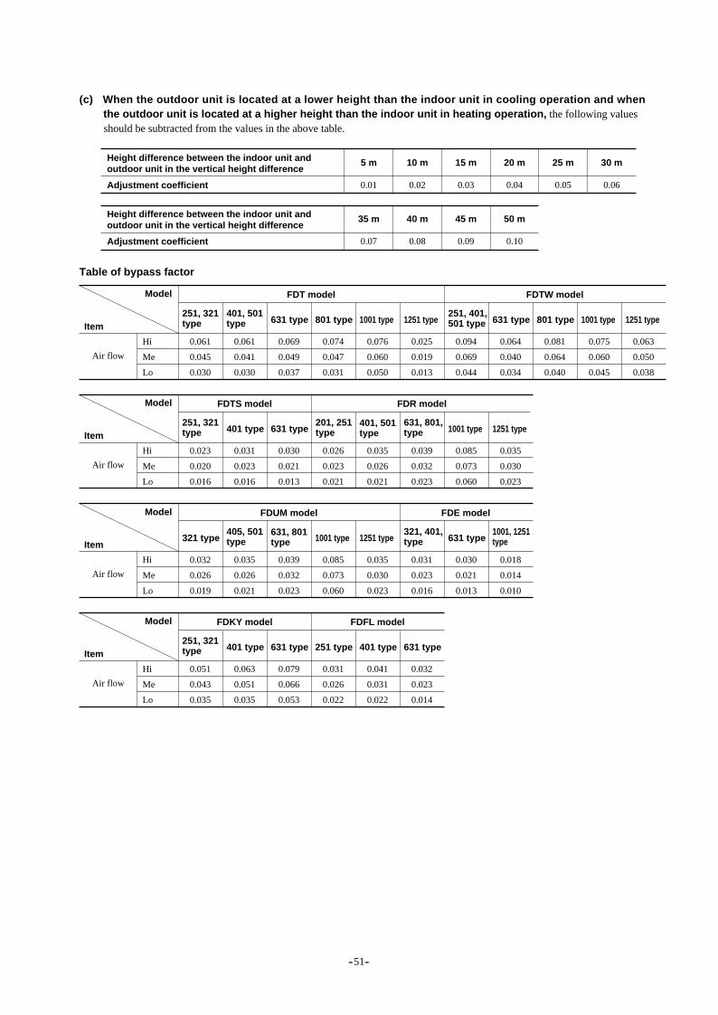
(c) When the outdoor unit is located at a lower height than the indoor unit in cooling operation and when the outdoor unit is located at a higher height than the indoor unit in heating operation, the following values should be subtracted from the values in the above table.
Height difference between the indoor unit and outdoor unit in the vertical height difference
Adjustment coefficient
5 m
0.01
10 m
0.02
15 m
0.03
20 m
0.04
25 m
0.05
30 m
0.06
Height difference between the indoor unit and outdoor unit in the vertical height difference
Adjustment coefficient
35 m
0.07
40 m
0.08
45 m
0.09
50 m
0.10
Table of bypass factor
Model
251, 321typeItem
Air flow
Hi
Me
Lo
0.061
0.045
0.030
401, 501type
0.061
0.041
0.030
631 type
0.069
0.049
0.037
801 type
0.074
0.047
0.031
1001 type
0.076
0.060
0.050
1251 type
0.025
0.019
0.013
251, 401,501 type
0.094
0.069
0.044
631 type
0.064
0.040
0.034
801 type
0.081
0.064
0.040
1001 type
0.075
0.060
0.045
1251 type
0.063
0.050
0.038
FDT model FDTW model
Model
251, 321typeItem
Air flow
Hi
Me
Lo
0.023
0.020
0.016
401 type
0.031
0.023
0.016
631 type
0.030
0.021
0.013
0.026
0.023
0.021
401, 501type
0.035
0.026
0.021
631, 801,type
0.039
0.032
0.023
1001 type201, 251type
0.085
0.073
0.060
1251 type
0.035
0.030
0.023
FDTS model FDR model
Model
321 typeItem
Air flow
Hi
Me
Lo
0.032
0.026
0.019
405, 501type
0.035
0.026
0.021
631, 801type
0.039
0.032
0.023
1001 type
0.085
0.073
0.060
1251 type
0.035
0.030
0.023
321, 401,type
0.031
0.023
0.016
631 type
0.030
0.021
0.013
1001, 1251type
0.018
0.014
0.010
FDUM model FDE model
Model
251, 321typeItem
Air flow
Hi
Me
Lo
0.051
0.043
0.035
401 type
0.063
0.051
0.035
631 type
0.079
0.066
0.053
251 type
0.031
0.026
0.022
401 type
0.041
0.031
0.022
631 type
0.032
0.023
0.014
FDKY model FDFL model
-- 51--

Correction of outdoor unit capacity according to capacity of indoor unit to be operated simultaneously
-- 52--
FDC2501HKXRE2
Notes (1) MAX: Frequency 95Hz MIN: Frequency 35Hz (2) The range marked with is for indoor unit only or indicates that small number of units are operated.
FDC2001HKXRE2
Notes (1) MAX: Frequency 95Hz MIN: Frequency 35Hz (2) The range marked with is for indoor unit only or indicates that small number of units are operated.
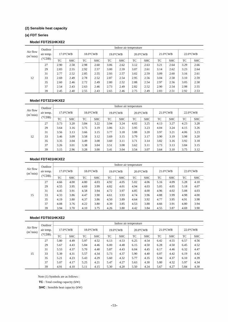
(2) Sensible heat capacity
(a) FDT Series
Model FDT251HKXE2
12
Outdoor
air temp.
(°CDB)
27
29
31
33
35
37
39
Indoor air temperature
17.0°CWB
TC
2.90
2.83
2.77
2.69
2.60
2.54
2.45
SHC
2.58
2.55
2.52
2.49
2.46
2.43
2.40
18.0°CWB
TC
2.98
2.92
2.85
2.78
2.72
2.63
2.55
SHC
2.60
2.57
2.55
2.52
2.49
2.46
2.43
19.0°CWB
TC
3.06
3.00
2.93
2.87
2.80
2.73
2.65
SHC
2.62
2.59
2.57
2.54
2.52
2.49
2.46
20.0°CWB
TC
3.12
3.07
3.02
2.95
2.88
2.82
2.75
SHC
2.63
2.61
2.59
2.56
2.54
2.52
2.49
21.0°CWB
TC
3.21
3.14
3.09
3.04
2.97
2.90
2.83
SHC
2.64
2.62
2.60
2.58
2.56
2.54
2.51
22.0°CWB
TC
3.29
3.23
3.16
3.10
3.05
2.98
2.92
SHC
2.66
2.64
2.61
2.59
2.58
2.55
2.53
Air flow
(m3/min)
Model FDT321HKXE2
12
Outdoor
air temp.
(°CDB)
27
29
31
33
35
37
39
Indoor air temperature
17.0°CWB
TC
3.73
3.64
3.56
3.46
3.35
3.26
3.15
SHC
3.20
3.16
3.13
3.09
3.04
3.01
2.96
18.0°CWB
TC
3.84
3.75
3.66
3.58
3.49
3.38
3.28
SHC
3.22
3.19
3.15
3.12
3.08
3.04
3.00
19.0°CWB
TC
3.94
3.86
3.77
3.69
3.60
3.51
3.41
SHC
3.24
3.21
3.18
3.15
3.11
3.08
3.04
20.0°CWB
TC
4.02
3.95
3.88
3.79
3.71
3.62
3.54
SHC
3.25
3.23
3.20
3.17
3.14
3.11
3.07
21.0°CWB
TC
4.13
4.04
3.97
3.90
3.82
3.73
3.64
SHC
3.27
3.24
3.21
3.19
3.16
3.13
3.10
22.0°CWB
TC
4.23
4.15
4.06
3.98
3.92
3.84
3.75
SHC
3.28
3.26
3.23
3.20
3.18
3.15
3.12
Air flow
(m3/min)
Model FDT401HKXE2
15
Outdoor
air temp.
(°CDB)
27
29
31
33
35
37
39
Indoor air temperature
17.0°CWB
TC
4.66
4.55
4.45
4.33
4.19
4.08
3.94
SHC
4.00
3.95
3.91
3.86
3.80
3.76
3.70
18.0°CWB
TC
4.80
4.69
4.58
4.47
4.37
4.22
4.10
SHC
4.03
3.99
3.94
3.90
3.86
3.80
3.75
19.0°CWB
TC
4.92
4.82
4.72
4.61
4.50
4.39
4.26
SHC
4.05
4.01
3.97
3.93
3.89
3.85
3.80
20.0°CWB
TC
5.02
4.94
4.85
4.74
4.64
4.53
4.42
SHC
4.06
4.03
4.00
3.96
3.92
3.88
3.84
21.0°CWB
TC
5.16
5.05
4.96
4.88
4.77
4.66
4.55
SHC
4.09
4.05
4.02
3.99
3.95
3.91
3.87
22.0°CWB
TC
5.28
5.18
5.08
4.98
4.91
4.80
4.69
SHC
4.10
4.07
4.03
4.00
3.98
3.94
3.90
Air flow
(m3/min)
Model FDT501HKXE2
15
Outdoor
air temp.
(°CDB)
27
29
31
33
35
37
39
Indoor air temperature
17.0°CWB
TC
5.80
5.67
5.53
5.39
5.21
5.07
4.91
SHC
4.49
4.43
4.37
4.31
4.23
4.17
4.10
18.0°CWB
TC
5.97
5.84
5.70
5.57
5.43
5.25
5.11
SHC
4.52
4.46
4.40
4.34
4.29
4.21
4.15
19.0°CWB
TC
6.13
6.00
5.87
5.73
5.60
5.47
5.30
SHC
4.53
4.48
4.43
4.37
4.32
4.27
4.20
20.0°CWB
TC
6.25
6.15
6.04
5.90
5.77
5.63
5.50
SHC
4.54
4.50
4.45
4.40
4.35
4.30
4.24
21.0°CWB
TC
6.42
6.28
6.17
6.07
5.94
5.80
5.67
SHC
4.55
4.50
4.46
4.42
4.37
4.32
4.27
22.0°CWB
TC
6.57
6.45
6.32
6.19
6.10
5.97
5.84
SHC
4.56
4.52
4.47
4.42
4.39
4.34
4.30
Air flow
(m3/min)
Note (1) Symbols are as follows :
TC : Total cooling capacity (kW)
SHC : Sensible heat capacity (kW)
-- 53--

Model FDT631HKXE2
16
Outdoor
air temp.
(°CDB)
27
29
31
33
35
37
39
Indoor air temperature
17.0°CWB
TC
7.36
7.19
7.01
6.83
6.60
6.43
6.22
SHC
5.32
5.24
5.16
5.08
4.97
4.90
4.80
18.0°CWB
TC
7.57
7.40
7.23
7.06
6.89
6.66
6.48
SHC
5.35
5.27
5.19
5.12
5.04
4.94
4.86
19.0°CWB
TC
7.77
7.61
7.44
7.27
7.10
6.93
6.72
SHC
5.36
5.29
5.22
5.15
5.07
5.00
4.91
20.0°CWB
TC
7.92
7.80
7.65
7.48
7.31
7.14
6.97
SHC
5.35
5.30
5.24
5.17
5.10
5.03
4.96
21.0°CWB
TC
8.14
7.97
7.82
7.70
7.53
7.36
7.19
SHC
5.36
5.29
5.24
5.19
5.12
5.05
4.99
22.0°CWB
TC
8.34
8.18
8.01
7.85
7.74
7.57
7.40
SHC
5.36
5.30
5.24
5.18
5.14
5.07
5.01
Air flow
(m3/min)
Model FDT801HKXE2
20
Outdoor
air temp.
(°CDB)
27
29
31
33
35
37
39
Indoor air temperature
17.0°CWB
TC
9.32
9.11
8.89
8.66
8.37
8.15
7.88
SHC
6.71
6.61
6.51
6.40
6.27
6.17
6.05
18.0°CWB
TC
9.59
9.38
9.16
8.95
8.73
8.44
8.21
SHC
6.74
6.64
6.55
6.45
6.36
6.23
6.13
19.0°CWB
TC
9.85
9.65
9.43
9.22
9.00
8.78
8.51
SHC
6.76
6.67
6.58
6.49
6.39
6.30
6.19
20.0°CWB
TC
10.04
9.88
9.70
9.49
9.27
9.05
8.84
SHC
6.75
6.68
6.60
6.52
6.43
6.34
6.25
21.0°CWB
TC
10.31
10.10
9.92
9.76
9.54
9.32
9.11
SHC
6.76
6.67
6.60
6.54
6.45
6.37
6.28
22.0°CWB
TC
10.57
10.37
10.15
9.95
9.81
9.59
9.38
SHC
6.76
6.69
6.60
6.53
6.47
6.39
6.31
Air flow
(m3/min)
Model FDT1001HKXE2
28
Outdoor
air temp.
(°CDB)
27
29
31
33
35
37
39
Indoor air temperature
17.0°CWB
TC
11.60
11.33
11.07
10.77
10.42
10.15
9.81
SHC
8.72
8.60
8.48
8.35
8.20
8.08
7.93
18.0°CWB
TC
11.94
11.67
11.40
11.13
10.86
10.51
10.21
SHC
8.77
8.66
8.54
8.42
8.31
8.16
8.04
19.0°CWB
TC
12.25
12.01
11.74
11.47
11.20
10.93
10.60
SHC
8.80
8.70
8.59
8.48
8.37
8.26
8.12
20.0°CWB
TC
12.50
12.30
12.07
11.80
11.54
11.27
11.00
SHC
8.80
8.72
8.63
8.52
8.42
8.31
8.20
21.0°CWB
TC
12.84
12.57
12.34
12.14
11.87
11.60
11.33
SHC
8.83
8.72
8.64
8.56
8.46
8.36
8.26
22.0°CWB
TC
13.15
12.90
12.63
12.39
12.21
11.94
11.67
SHC
8.84
8.75
8.65
8.56
8.49
8.39
8.30
Air flow
(m3/min)
Model FDT1251HKXE2
30
Outdoor
air temp.
(°CDB)
27
29
31
33
35
37
39
Indoor air temperature
17.0°CWB
TC
14.50
14.17
13.83
13.47
13.02
12.68
12.26
SHC
10.31
10.15
9.99
9.82
9.62
9.46
9.27
18.0°CWB
TC
14.92
14.59
14.25
13.92
13.58
13.13
12.77
SHC
10.36
10.20
10.05
9.90
9.75
9.55
9.39
19.0°CWB
TC
15.32
15.01
14.67
14.34
14.00
13.66
13.24
SHC
10.38
10.25
10.10
9.95
9.81
9.66
9.48
20.0°CWB
TC
15.62
15.37
15.09
14.76
14.42
14.08
13.75
SHC
10.36
10.25
10.13
9.99
9.85
9.71
9.57
21.0°CWB
TC
16.04
15.71
15.43
15.18
14.84
14.50
14.17
SHC
10.38
10.24
10.13
10.02
9.89
9.76
9.62
22.0°CWB
TC
16.44
16.13
15.79
15.48
15.26
14.92
14.59
SHC
10.38
10.25
10.12
10.00
9.92
9.79
9.66
Air flow
(m3/min)
Note (1) Symbols are as follows :
TC : Total cooling capacity (kW)
SHC : Sensible heat capacity (kW)
-- 54--

(b) FDTW Series
Model FDTW251HKXE2
15
Outdoor
air temp.
(°CDB)
27
29
31
33
35
37
39
Indoor air temperature
17.0°CWB
TC
2.90
2.83
2.77
2.69
2.60
2.54
2.45
SHC
2.58
2.55
2.52
2.49
2.46
2.43
2.40
18.0°CWB
TC
2.98
2.92
2.85
2.78
2.72
2.63
2.55
SHC
2.60
2.57
2.55
2.52
2.49
2.46
2.43
19.0°CWB
TC
3.06
3.00
2.93
2.87
2.80
2.73
2.65
SHC
2.62
2.59
2.57
2.54
2.52
2.49
2.46
20.0°CWB
TC
3.12
3.07
3.02
2.95
2.88
2.82
2.75
SHC
2.63
2.61
2.59
2.56
2.54
2.52
2.49
21.0°CWB
TC
3.21
3.14
3.09
3.04
2.97
2.90
2.83
SHC
2.64
2.62
2.60
2.58
2.56
2.54
2.51
22.0°CWB
TC
3.29
3.23
3.16
3.10
3.05
2.98
2.92
SHC
2.66
2.64
2.61
2.59
2.58
2.55
2.53
Air flow
(m3/min)
Model FDTW401HKXE2
15
Outdoor
air temp.
(°CDB)
27
29
31
33
35
37
39
Indoor air temperature
17.0°CWB
TC
4.66
4.55
4.45
4.33
4.19
4.08
3.94
SHC
4.00
3.95
3.91
3.86
3.80
3.76
3.70
18.0°CWB
TC
4.80
4.69
4.58
4.47
4.37
4.22
4.10
SHC
4.03
3.99
3.94
3.90
3.86
3.80
3.75
19.0°CWB
TC
4.92
4.82
4.72
4.61
4.50
4.39
4.26
SHC
4.05
4.01
3.97
3.93
3.89
3.85
3.80
20.0°CWB
TC
5.02
4.94
4.85
4.74
4.64
4.53
4.42
SHC
4.06
4.03
4.00
3.96
3.92
3.88
3.84
21.0°CWB
TC
5.16
5.05
4.96
4.88
4.77
4.66
4.55
SHC
4.09
4.05
4.02
3.99
3.95
3.91
3.87
22.0°CWB
TC
5.28
5.18
5.08
4.98
4.91
4.80
4.69
SHC
4.10
4.07
4.03
4.00
3.98
3.94
3.90
Air flow
(m3/min)
Model FDTW501HKXE2
15
Outdoor
air temp.
(°CDB)
27
29
31
33
35
37
39
Indoor air temperature
17.0°CWB
TC
5.80
5.67
5.53
5.39
5.21
5.07
4.91
SHC
4.49
4.43
4.37
4.31
4.23
4.17
4.10
18.0°CWB
TC
5.97
5.84
5.70
5.57
5.43
5.25
5.11
SHC
4.52
4.46
4.40
4.34
4.29
4.21
4.15
19.0°CWB
TC
6.13
6.00
5.87
5.73
5.60
5.47
5.30
SHC
4.53
4.48
4.43
4.37
4.32
4.27
4.20
20.0°CWB
TC
6.25
6.15
6.04
5.90
5.77
5.63
5.50
SHC
4.54
4.50
4.45
4.40
4.35
4.30
4.24
21.0°CWB
TC
6.24
6.28
6.17
6.07
5.94
5.80
5.67
SHC
4.55
4.50
4.46
4.42
4.37
4.32
4.27
22.0°CWB
TC
6.57
6.45
6.32
6.19
6.10
5.97
5.84
SHC
4.56
4.52
4.47
4.42
4.39
4.34
4.30
Air flow
(m3/min)
Model FDTW631HKXE2
16
Outdoor
air temp.
(°CDB)
27
29
31
33
35
37
39
Indoor air temperature
17.0°CWB
TC
7.36
7.19
7.01
6.83
6.60
6.43
6.22
SHC
5.32
5.24
5.16
5.08
4.97
4.90
4.80
18.0°CWB
TC
7.57
7.40
7.23
7.06
6.89
6.66
6.48
SHC
5.35
5.27
5.19
5.12
5.04
4.94
4.86
19.0°CWB
TC
7.77
7.61
7.44
7.27
7.10
6.93
6.72
SHC
5.36
5.29
5.22
5.15
5.07
5.00
4.91
20.0°CWB
TC
7.92
7.80
7.65
7.48
7.31
7.14
6.97
SHC
5.35
5.30
5.24
5.17
5.10
5.03
4.96
21.0°CWB
TC
8.14
7.97
7.82
7.70
7.53
7.36
7.19
SHC
5.36
5.29
5.24
5.19
5.12
5.05
4.99
22.0°CWB
TC
8.34
8.18
8.01
7.85
7.74
7.57
7.40
SHC
5.36
5.30
5.24
5.18
5.14
5.07
5.01
Air flow
(m3/min)
Note (1) Symbols are as follows :
TC : Total cooling capacity (kW)
SHC : Sensible heat capacity (kW)
-- 55--
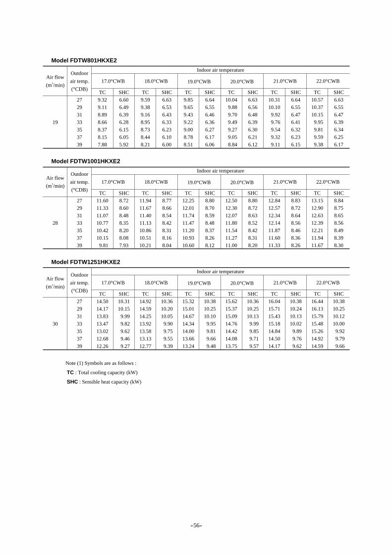
Model FDTW801HKXE2
19
Outdoor
air temp.
(°CDB)
27
29
31
33
35
37
39
Indoor air temperature
17.0°CWB
TC
9.32
9.11
8.89
8.66
8.37
8.15
7.88
SHC
6.60
6.49
6.39
6.28
6.15
6.05
5.92
18.0°CWB
TC
9.59
9.38
9.16
8.95
8.73
8.44
8.21
SHC
6.63
6.53
6.43
6.33
6.23
6.10
6.00
19.0°CWB
TC
9.85
9.65
9.43
9.22
9.00
8.78
8.51
SHC
6.64
6.55
6.46
6.36
6.27
6.17
6.06
20.0°CWB
TC
10.04
9.88
9.70
9.49
9.27
9.05
8.84
SHC
6.63
6.56
6.48
6.39
6.30
6.21
6.12
21.0°CWB
TC
10.31
10.10
9.92
9.76
9.54
9.32
9.11
SHC
6.64
6.55
6.47
6.41
6.32
6.23
6.15
22.0°CWB
TC
10.57
10.37
10.15
9.95
9.81
9.59
9.38
SHC
6.63
6.55
6.47
6.39
6.34
6.25
6.17
Air flow
(m3/min)
Model FDTW1001HKXE2
28
Outdoor
air temp.
(°CDB)
27
29
31
33
35
37
39
Indoor air temperature
17.0°CWB
TC
11.60
11.33
11.07
10.77
10.42
10.15
9.81
SHC
8.72
8.60
8.48
8.35
8.20
8.08
7.93
18.0°CWB
TC
11.94
11.67
11.40
11.13
10.86
10.51
10.21
SHC
8.77
8.66
8.54
8.42
8.31
8.16
8.04
19.0°CWB
TC
12.25
12.01
11.74
11.47
11.20
10.93
10.60
SHC
8.80
8.70
8.59
8.48
8.37
8.26
8.12
20.0°CWB
TC
12.50
12.30
12.07
11.80
11.54
11.27
11.00
SHC
8.80
8.72
8.63
8.52
8.42
8.31
8.20
21.0°CWB
TC
12.84
12.57
12.34
12.14
11.87
11.60
11.33
SHC
8.83
8.72
8.64
8.56
8.46
8.36
8.26
22.0°CWB
TC
13.15
12.90
12.63
12.39
12.21
11.94
11.67
SHC
8.84
8.75
8.65
8.56
8.49
8.39
8.30
Air flow
(m3/min)
Model FDTW1251HKXE2
30
Outdoor
air temp.
(°CDB)
27
29
31
33
35
37
39
Indoor air temperature
17.0°CWB
TC
14.50
14.17
13.83
13.47
13.02
12.68
12.26
SHC
10.31
10.15
9.99
9.82
9.62
9.46
9.27
18.0°CWB
TC
14.92
14.59
14.25
13.92
13.58
13.13
12.77
SHC
10.36
10.20
10.05
9.90
9.75
9.55
9.39
19.0°CWB
TC
15.32
15.01
14.67
14.34
14.00
13.66
13.24
SHC
10.38
10.25
10.10
9.95
9.81
9.66
9.48
20.0°CWB
TC
15.62
15.37
15.09
14.76
14.42
14.08
13.75
SHC
10.36
10.25
10.13
9.99
9.85
9.71
9.57
21.0°CWB
TC
16.04
15.71
15.43
15.18
14.84
14.50
14.17
SHC
10.38
10.24
10.13
10.02
9.89
9.76
9.62
22.0°CWB
TC
16.44
16.13
15.79
15.48
15.26
14.92
14.59
SHC
10.38
10.25
10.12
10.00
9.92
9.79
9.66
Air flow
(m3/min)
Note (1) Symbols are as follows :
TC : Total cooling capacity (kW)
SHC : Sensible heat capacity (kW)
-- 56--

(c) FDTS Series
Model FDTS251HKXE2
12
Outdoor
air temp.
(°CDB)
27
29
31
33
35
37
39
Indoor air temperature
17.0°CWB
TC
2.90
2.83
2.77
2.69
2.60
2.54
2.45
SHC
2.58
2.55
2.52
2.49
2.46
2.43
2.40
18.0°CWB
TC
2.98
2.92
2.85
2.78
2.72
2.63
2.55
SHC
2.60
2.57
2.55
2.52
2.49
2.46
2.43
19.0°CWB
TC
3.06
3.00
2.93
2.87
2.80
2.73
2.65
SHC
2.62
2.59
2.57
2.54
2.52
2.49
2.46
20.0°CWB
TC
3.12
3.07
3.02
2.95
2.88
2.82
2.75
SHC
2.63
2.61
2.59
2.56
2.54
2.52
2.49
21.0°CWB
TC
3.21
3.14
3.09
3.04
2.97
2.90
2.83
SHC
2.64
2.62
2.60
2.58
2.56
2.54
2.51
22.0°CWB
TC
3.29
3.23
3.16
3.10
3.05
2.98
2.92
SHC
2.66
2.64
2.61
2.59
2.58
2.55
2.53
Air flow
(m3/min)
Model FDTS321HKXE2
12
Outdoor
air temp.
(°CDB)
27
29
31
33
35
37
39
Indoor air temperature
17.0°CWB
TC
3.73
3.64
3.56
3.46
3.35
3.26
3.15
SHC
3.20
3.16
3.13
3.09
3.04
3.01
2.96
18.0°CWB
TC
3.84
3.75
3.66
3.58
3.49
3.38
3.28
SHC
3.22
3.19
3.15
3.12
3.08
3.04
3.00
19.0°CWB
TC
3.94
3.86
3.77
3.69
3.60
3.51
3.41
SHC
3.24
3.21
3.18
3.15
3.11
3.08
3.04
20.0°CWB
TC
4.02
3.95
3.88
3.79
3.71
3.62
3.54
SHC
3.25
3.23
3.20
3.17
3.14
3.11
3.07
21.0°CWB
TC
4.13
4.04
3.97
3.90
3.82
3.73
3.64
SHC
3.27
3.24
3.21
3.19
3.16
3.13
3.10
22.0°CWB
TC
4.23
4.15
4.06
3.98
3.92
3.84
3.75
SHC
3.28
3.26
3.23
3.20
3.18
3.15
3.12
Air flow
(m3/min)
Model FDTS401HKXE2
14
Outdoor
air temp.
(°CDB)
27
29
31
33
35
37
39
Indoor air temperature
17.0°CWB
TC
4.66
4.55
4.45
4.33
4.19
4.08
3.94
SHC
3.86
3.82
3.77
3.72
3.66
3.62
3.56
18.0°CWB
TC
4.80
4.69
4.58
4.47
4.37
4.22
4.10
SHC
3.89
3.85
3.80
3.76
3.71
3.66
3.61
19.0°CWB
TC
4.92
4.82
4.72
4.61
4.50
4.39
4.26
SHC
3.91
3.87
3.83
3.79
3.75
3.70
3.65
20.0°CWB
TC
5.02
4.94
4.85
4.74
4.64
4.53
4.42
SHC
3.92
3.89
3.85
3.81
3.77
3.73
3.69
21.0°CWB
TC
5.16
5.05
5.96
4.88
4.77
4.66
4.55
SHC
3.94
3.90
3.87
3.84
3.80
3.76
3.72
22.0°CWB
TC
5.28
5.18
5.08
4.98
4.91
4.80
4.69
SHC
3.95
3.92
3.88
3.85
3.82
3.78
3.75
Air flow
(m3/min)
Model FDTS631HKXE2
18
Outdoor
air temp.
(°CDB)
27
29
31
33
35
37
39
Indoor air temperature
17.0°CWB
TC
7.36
7.19
7.01
6.83
6.60
6.43
6.22
SHC
5.56
5.49
5.41
5.33
5.23
5.15
5.06
18.0°CWB
TC
7.57
7.40
7.23
7.06
6.89
6.66
6.48
SHC
5.59
5.52
5.45
5.37
5.30
5.21
5.13
19.0°CWB
TC
7.77
7.61
7.44
7.27
7.10
6.93
6.72
SHC
5.61
5.55
5.48
5.41
5.34
5.27
5.18
20.0°CWB
TC
7.92
7.80
7.65
7.48
7.31
7.14
6.97
SHC
5.61
5.56
5.50
5.44
5.37
5.30
5.24
21.0°CWB
TC
8.14
7.97
7.82
7.70
7.53
7.36
7.19
SHC
5.63
5.57
5.51
5.46
5.40
5.33
5.27
22.0°CWB
TC
8.34
8.18
8.01
7.85
7.74
7.57
7.40
SHC
5.64
5.58
5.52
5.46
5.42
5.36
5.30
Air flow
(m3/min)
Note (1) Symbols are as follows :
TC : Total cooling capacity (kW)
SHC : Sensible heat capacity (kW)
-- 57--

(d) FDR Series
Model FDR201HKXE2
10
Outdoor
air temp.
(°CDB)
27
29
31
33
35
37
39
Indoor air temperature
17.0°CWB
TC
2.28
2.23
2.17
2.12
2.05
1.99
1.93
SHC
2.05
2.02
2.00
1.98
1.95
1.93
1.90
18.0°CWB
TC
2.35
2.29
2.24
2.19
2.13
2.06
2.01
SHC
2.06
2.04
2.02
2.00
1.98
1.95
1.93
19.0°CWB
TC
2.41
2.36
2.31
2.25
2.20
2.15
2.08
SHC
2.08
2.06
2.04
2.02
2.00
1.98
1.96
20.0°CWB
TC
2.46
2.42
2.37
2.32
2.27
2.21
2.16
SHC
2.09
2.07
2.06
2.04
2.02
2.00
1.98
21.0°CWB
TC
2.52
2.47
2.42
2.38
2.33
2.28
2.23
SHC
2.10
2.08
2.06
2.05
2.03
2.01
2.00
22.0°CWB
TC
2.58
2.53
2.48
2.43
2.40
2.35
2.29
SHC
2.11
2.09
2.08
2.06
2.05
2.03
2.01
Air flow
(m3/min)
Model FDR251HKXE2
12
Outdoor
air temp.
(°CDB)
27
29
31
33
35
37
39
Indoor air temperature
17.0°CWB
TC
2.90
2.83
2.77
2.69
2.60
2.54
2.45
SHC
2.58
2.55
2.52
2.49
2.46
2.43
2.40
18.0°CWB
TC
2.98
2.92
2.85
2.78
2.72
2.63
2.55
SHC
2.60
2.57
2.55
2.52
2.49
2.46
2.43
19.0°CWB
TC
3.06
3.00
2.93
2.87
2.80
2.73
2.65
SHC
2.62
2.59
2.57
2.54
2.52
2.49
2.46
20.0°CWB
TC
3.12
3.07
3.02
2.95
2.88
2.82
2.75
SHC
2.63
2.61
2.59
2.56
2.54
2.52
2.49
21.0°CWB
TC
3.21
3.14
3.09
3.04
2.97
2.90
2.83
SHC
2.64
2.62
2.60
2.58
2.56
2.54
2.51
22.0°CWB
TC
3.29
3.23
3.16
3.10
3.05
2.98
2.92
SHC
2.66
2.64
2.61
2.59
2.58
2.55
2.53
Air flow
(m3/min)
Model FDR401HKXE2
14
Outdoor
air temp.
(°CDB)
27
29
31
33
35
37
39
Indoor air temperature
17.0°CWB
TC
4.66
4.55
4.45
4.33
4.19
4.08
3.94
SHC
3.86
3.82
3.77
3.72
3.66
3.62
3.56
18.0°CWB
TC
4.80
4.69
4.58
4.47
4.37
4.22
4.10
SHC
3.89
3.85
3.80
3.76
3.71
3.66
3.61
19.0°CWB
TC
4.92
4.82
4.72
4.61
4.50
4.39
4.26
SHC
3.91
3.87
3.83
3.79
3.75
3.70
3.65
20.0°CWB
TC
5.02
4.94
4.85
4.74
4.64
4.53
4.42
SHC
3.92
3.89
3.85
3.81
3.77
3.73
3.69
21.0°CWB
TC
5.16
5.05
4.96
4.88
4.77
4.66
4.55
SHC
3.94
3.90
3.87
3.84
3.80
3.76
3.72
22.0°CWB
TC
5.28
5.18
5.08
4.98
4.91
4.80
4.69
SHC
3.95
3.92
3.88
3.85
3.82
3.78
3.75
Air flow
(m3/min)
Model FDR501HKXE2
14
Outdoor
air temp.
(°CDB)
27
29
31
33
35
37
39
Indoor air temperature
17.0°CWB
TC
5.80
5.67
5.53
5.39
5.21
5.07
4.91
SHC
4.36
4.30
4.24
4.18
4.10
4.04
3.97
18.0°CWB
TC
5.97
5.84
5.70
5.57
5.43
5.25
5.11
SHC
4.39
4.33
4.27
4.21
4.16
4.08
4.02
19.0°CWB
TC
6.13
6.00
5.87
5.73
5.60
5.47
5.30
SHC
4.40
4.35
4.29
4.24
4.18
4.13
4.06
20.0°CWB
TC
6.25
6.15
6.04
5.90
5.77
5.63
5.50
SHC
4.40
4.36
4.32
4.26
4.21
4.16
4.10
21.0°CWB
TC
6.42
6.28
6.17
6.07
5.94
5.80
5.67
SHC
4.41
4.36
4.32
4.28
4.23
4.18
4.13
22.0°CWB
TC
6.57
6.45
6.32
6.19
6.10
5.97
5.84
SHC
4.42
4.37
4.32
4.28
4.25
4.20
4.15
Air flow
(m3/min)
Note (1) Symbols are as follows :
TC : Total cooling capacity (kW)
SHC : Sensible heat capacity (kW)
-- 58--

Model FDR631HKXE2
18
Outdoor
air temp.
(°CDB)
27
29
31
33
35
37
39
Indoor air temperature
17.0°CWB
TC
7.36
7.19
7.01
6.83
6.60
6.43
6.22
SHC
5.56
5.49
5.41
5.33
5.23
5.15
5.06
18.0°CWB
TC
7.57
7.40
7.23
7.06
6.89
6.66
6.48
SHC
5.59
5.52
5.45
5.37
5.30
5.21
5.13
19.0°CWB
TC
7.77
7.61
7.44
7.27
7.10
6.93
6.72
SHC
5.61
5.55
5.48
5.41
5.34
5.27
5.18
20.0°CWB
TC
7.92
7.80
7.65
7.48
7.31
7.14
6.97
SHC
5.61
5.56
5.50
5.44
5.37
5.30
5.24
21.0°CWB
TC
8.14
7.97
7.82
7.70
7.53
7.36
7.19
SHC
5.63
5.57
5.51
5.46
5.40
5.33
5.27
22.0°CWB
TC
8.34
8.18
8.01
7.85
7.74
7.57
7.40
SHC
5.64
5.58
5.52
5.46
5.42
5.36
5.30
Air flow
(m3/min)
Model FDR801HKXE2
20
Outdoor
air temp.
(°CDB)
27
29
31
33
35
37
39
Indoor air temperature
17.0°CWB
TC
9.32
9.11
8.89
8.66
8.37
8.15
7.88
SHC
6.71
6.61
6.51
6.40
6.27
6.17
6.05
18.0°CWB
TC
9.59
9.38
9.16
8.95
8.73
8.44
8.21
SHC
6.74
6.64
6.55
6.45
6.36
6.23
6.13
19.0°CWB
TC
9.85
9.65
9.43
9.22
9.00
8.78
8.51
SHC
6.76
6.67
6.58
6.49
6.39
6.30
6.19
20.0°CWB
TC
10.04
9.88
9.70
9.49
9.27
9.05
8.84
SHC
6.75
6.68
6.60
6.52
6.43
6.34
6.25
21.0°CWB
TC
10.31
10.10
9.92
9.76
9.54
9.32
9.11
SHC
6.76
6.67
6.60
6.54
6.45
6.37
6.28
22.0°CWB
TC
10.57
10.37
10.15
9.95
9.81
9.59
9.38
SHC
6.76
6.69
6.60
6.53
6.47
6.39
6.31
Air flow
(m3/min)
Model FDR1001HKXE2
28
Outdoor
air temp.
(°CDB)
27
29
31
33
35
37
39
Indoor air temperature
17.0°CWB
TC
11.60
11.33
11.07
10.77
10.42
10.15
9.81
SHC
8.72
8.60
8.48
8.35
8.20
8.08
7.93
18.0°CWB
TC
11.94
11.67
11.40
11.13
10.86
10.51
10.21
SHC
8.77
8.66
8.54
8.42
8.31
8.16
8.04
19.0°CWB
TC
12.25
12.01
11.74
11.47
11.20
10.93
10.60
SHC
8.80
8.70
8.59
8.48
8.37
8.26
8.12
20.0°CWB
TC
12.50
12.30
12.07
11.80
11.54
11.27
11.00
SHC
8.80
8.72
8.63
8.52
8.42
8.31
8.20
21.0°CWB
TC
12.84
12.57
12.34
12.14
11.87
11.60
11.33
SHC
8.83
8.72
8.64
8.56
8.46
8.36
8.26
22.0°CWB
TC
13.15
12.90
12.63
12.39
12.21
11.94
11.67
SHC
8.84
8.75
8.65
8.56
8.49
8.39
8.30
Air flow
(m3/min)
Model FDR1251HKXE2
34
Outdoor
air temp.
(°CDB)
27
29
31
33
35
37
39
Indoor air temperature
17.0°CWB
TC
14.50
14.17
13.83
13.47
13.02
12.68
12.26
SHC
10.78
10.63
10.48
10.31
10.12
9.97
9.78
18.0°CWB
TC
14.92
14.59
14.25
13.92
13.58
13.13
12.77
SHC
10.84
10.69
10.55
10.40
10.26
10.07
9.91
19.0°CWB
TC
15.32
15.01
14.67
14.34
14.00
13.66
13.24
SHC
10.88
10.75
10.60
10.46
10.32
10.19
10.01
20.0°CWB
TC
15.62
15.37
15.09
14.76
14.42
14.08
13.75
SHC
10.87
10.77
10.65
10.52
10.38
10.25
10.12
21.0°CWB
TC
16.04
15.71
15.43
15.18
14.84
14.50
14.17
SHC
10.90
10.77
10.66
10.56
10.43
10.30
10.18
22.0°CWB
TC
16.44
16.13
15.79
15.48
15.26
14.92
14.59
SHC
10.91
10.80
10.67
10.56
10.47
10.35
10.23
Air flow
(m3/min)
Note (1) Symbols are as follows :
TC : Total cooling capacity (kW)
SHC : Sensible heat capacity (kW)
-- 59--
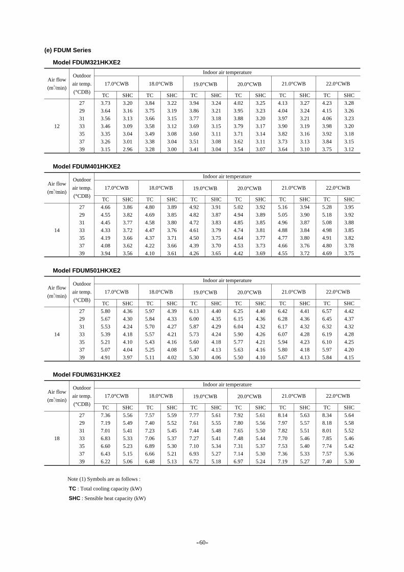
(e) FDUM Series
Model FDUM321HKXE2
12
Outdoor
air temp.
(°CDB)
27
29
31
33
35
37
39
Indoor air temperature
17.0°CWB
TC
3.73
3.64
3.56
3.46
3.35
3.26
3.15
SHC
3.20
3.16
3.13
3.09
3.04
3.01
2.96
18.0°CWB
TC
3.84
3.75
3.66
3.58
3.49
3.38
3.28
SHC
3.22
3.19
3.15
3.12
3.08
3.04
3.00
19.0°CWB
TC
3.94
3.86
3.77
3.69
3.60
3.51
3.41
SHC
3.24
3.21
3.18
3.15
3.11
3.08
3.04
20.0°CWB
TC
4.02
3.95
3.88
3.79
3.71
3.62
3.54
SHC
3.25
3.23
3.20
3.17
3.14
3.11
3.07
21.0°CWB
TC
4.13
4.04
3.97
3.90
3.82
3.73
3.64
SHC
3.27
3.24
3.21
3.19
3.16
3.13
3.10
22.0°CWB
TC
4.23
4.15
4.06
3.98
3.92
3.84
3.75
SHC
3.28
3.26
3.23
3.20
3.18
3.15
3.12
Air flow
(m3/min)
Model FDUM401HKXE2
14
Outdoor
air temp.
(°CDB)
27
29
31
33
35
37
39
Indoor air temperature
17.0°CWB
TC
4.66
4.55
4.45
4.33
4.19
4.08
3.94
SHC
3.86
3.82
3.77
3.72
3.66
3.62
3.56
18.0°CWB
TC
4.80
4.69
4.58
4.47
4.37
4.22
4.10
SHC
3.89
3.85
3.80
3.76
3.71
3.66
3.61
19.0°CWB
TC
4.92
4.82
4.72
4.61
4.50
4.39
4.26
SHC
3.91
3.87
3.83
3.79
3.75
3.70
3.65
20.0°CWB
TC
5.02
4.94
4.85
4.74
4.64
4.53
4.42
SHC
3.92
3.89
3.85
3.81
3.77
3.73
3.69
21.0°CWB
TC
5.16
5.05
4.96
4.88
4.77
4.66
4.55
SHC
3.94
3.90
3.87
3.84
3.80
3.76
3.72
22.0°CWB
TC
5.28
5.18
5.08
4.98
4.91
4.80
4.69
SHC
3.95
3.92
3.88
3.85
3.82
3.78
3.75
Air flow
(m3/min)
Model FDUM501HKXE2
14
Outdoor
air temp.
(°CDB)
27
29
31
33
35
37
39
Indoor air temperature
17.0°CWB
TC
5.80
5.67
5.53
5.39
5.21
5.07
4.91
SHC
4.36
4.30
4.24
4.18
4.10
4.04
3.97
18.0°CWB
TC
5.97
5.84
5.70
5.57
5.43
5.25
5.11
SHC
4.39
4.33
4.27
4.21
4.16
4.08
4.02
19.0°CWB
TC
6.13
6.00
5.87
5.73
5.60
5.47
5.30
SHC
4.40
4.35
4.29
4.24
4.18
4.13
4.06
20.0°CWB
TC
6.25
6.15
6.04
5.90
5.77
5.63
5.50
SHC
4.40
4.36
4.32
4.26
4.21
4.16
4.10
21.0°CWB
TC
6.42
6.28
6.17
6.07
5.94
5.80
5.67
SHC
4.41
4.36
4.32
4.28
4.23
4.18
4.13
22.0°CWB
TC
6.57
6.45
6.32
6.19
6.10
5.97
5.84
SHC
4.42
4.37
4.32
4.28
4.25
4.20
4.15
Air flow
(m3/min)
Model FDUM631HKXE2
18
Outdoor
air temp.
(°CDB)
27
29
31
33
35
37
39
Indoor air temperature
17.0°CWB
TC
7.36
7.19
7.01
6.83
6.60
6.43
6.22
SHC
5.56
5.49
5.41
5.33
5.23
5.15
5.06
18.0°CWB
TC
7.57
7.40
7.23
7.06
6.89
6.66
6.48
SHC
5.59
5.52
5.45
5.37
5.30
5.21
5.13
19.0°CWB
TC
7.77
7.61
7.44
7.27
7.10
6.93
6.72
SHC
5.61
5.55
5.48
5.41
5.34
5.27
5.18
20.0°CWB
TC
7.92
7.80
7.65
7.48
7.31
7.14
6.97
SHC
5.61
5.56
5.50
5.44
5.37
5.30
5.24
21.0°CWB
TC
8.14
7.97
7.82
7.70
7.53
7.36
7.19
SHC
5.63
5.57
5.51
5.46
5.40
5.33
5.27
22.0°CWB
TC
8.34
8.18
8.01
7.85
7.74
7.57
7.40
SHC
5.64
5.58
5.52
5.46
5.42
5.36
5.30
Air flow
(m3/min)
Note (1) Symbols are as follows :
TC : Total cooling capacity (kW)
SHC : Sensible heat capacity (kW)
-- 60--

Model FDUM801HKXE2
20
Outdoor
air temp.
(°CDB)
27
29
31
33
35
37
39
Indoor air temperature
17.0°CWB
TC
9.32
9.11
8.89
8.66
8.37
8.15
7.88
SHC
6.71
6.61
6.51
6.40
6.27
6.17
6.05
18.0°CWB
TC
9.59
9.38
9.16
8.95
8.73
8.44
8.21
SHC
6.74
6.64
6.55
6.45
6.36
6.23
6.13
19.0°CWB
TC
9.85
9.65
9.43
9.22
9.00
8.78
8.51
SHC
6.76
6.67
6.58
6.49
6.39
6.30
6.19
20.0°CWB
TC
10.04
9.88
9.70
9.49
9.27
9.05
8.84
SHC
6.75
6.68
6.60
6.52
6.43
6.34
6.25
21.0°CWB
TC
10.31
10.10
9.92
9.76
9.54
9.32
9.11
SHC
6.76
6.67
6.60
6.54
6.45
6.37
6.28
22.0°CWB
TC
10.57
10.37
10.15
9.95
9.81
9.59
9.38
SHC
6.76
6.69
6.60
6.53
6.47
6.39
6.31
Air flow
(m3/min)
Model FDUM1001HKXE2
28
Outdoor
air temp.
(°CDB)
27
29
31
33
35
37
39
Indoor air temperature
17.0°CWB
TC
11.60
11.33
11.07
10.77
10.42
10.15
9.81
SHC
8.72
8.60
8.48
8.35
8.20
8.08
7.93
18.0°CWB
TC
11.94
11.67
11.40
11.13
10.86
10.51
10.21
SHC
8.77
8.66
8.54
8.42
8.31
8.16
8.04
19.0°CWB
TC
12.25
12.01
11.74
11.47
11.20
10.93
10.60
SHC
8.80
8.70
8.59
8.48
8.37
8.26
8.12
20.0°CWB
TC
12.50
12.30
12.07
11.80
11.54
11.27
11.00
SHC
8.80
8.72
8.63
8.52
8.42
8.31
8.20
21.0°CWB
TC
12.84
12.57
12.34
12.14
11.87
11.60
11.33
SHC
8.83
8.72
8.64
8.56
8.46
8.36
8.26
22.0°CWB
TC
13.15
12.90
12.63
12.39
12.21
11.94
11.67
SHC
8.84
8.75
8.65
8.56
8.49
8.39
8.30
Air flow
(m3/min)
Model FDUM1251HKXE2
34
Outdoor
air temp.
(°CDB)
27
29
31
33
35
37
39
Indoor air temperature
17.0°CWB
TC
14.50
14.17
13.83
13.47
13.02
12.68
12.26
SHC
10.78
10.63
10.48
10.31
10.12
9.97
9.78
18.0°CWB
TC
14.92
14.59
14.25
13.92
13.58
13.13
12.77
SHC
10.84
10.69
10.55
10.40
10.26
10.07
9.91
19.0°CWB
TC
15.32
15.01
14.67
14.34
14.00
13.66
13.24
SHC
10.88
10.75
10.60
10.46
10.32
10.19
10.01
20.0°CWB
TC
15.62
15.37
15.09
14.76
14.42
14.08
13.75
SHC
10.87
10.77
10.65
10.52
10.38
10.25
10.12
21.0°CWB
TC
16.04
15.71
15.43
15.18
14.84
14.50
14.17
SHC
10.90
10.77
10.66
10.56
10.43
10.30
10.18
22.0°CWB
TC
16.44
16.13
15.79
15.48
15.26
14.92
14.59
SHC
10.91
10.80
10.67
10.56
10.47
10.35
10.23
Air flow
(m3/min)
Note (1) Symbols are as follows :
TC : Total cooling capacity (kW)
SHC : Sensible heat capacity (kW)
-- 61--

(f) FDE Series
Model FDE321HKXE2
14
Outdoor
air temp.
(°CDB)
27
29
31
33
35
37
39
Indoor air temperature
17.0°CWB
TC
3.73
3.64
3.56
3.46
3.35
3.26
3.15
SHC
3.34
3.30
3.26
3.23
3.18
3.15
3.10
18.0°CWB
TC
3.84
3.75
3.66
3.58
3.49
3.38
3.28
SHC
3.36
3.33
3.30
3.26
3.23
3.18
3.15
19.0°CWB
TC
3.94
3.86
3.77
3.69
3.60
3.51
3.41
SHC
3.39
3.36
3.32
3.29
3.26
3.23
3.19
20.0°CWB
TC
4.02
3.95
3.88
3.79
3.71
3.62
3.54
SHC
3.40
3.38
3.35
3.32
3.29
3.26
3.23
21.0°CWB
TC
4.13
4.04
3.97
3.90
3.82
3.73
3.64
SHC
3.42
3.39
3.37
3.34
3.31
3.28
3.25
22.0°CWB
TC
4.23
4.15
4.06
3.98
3.92
3.84
3.75
SHC
3.44
3.41
3.38
3.35
3.34
3.31
3.28
Air flow
(m3/min)
Model FDE401HKXE2
14
Outdoor
air temp.
(°CDB)
27
29
31
33
35
37
39
Indoor air temperature
17.0°CWB
TC
4.66
4.55
4.45
4.33
4.19
4.08
3.94
SHC
3.86
3.82
3.77
3.72
3.66
3.62
3.56
18.0°CWB
TC
4.80
4.69
4.58
4.47
4.37
4.22
4.10
SHC
3.89
3.85
3.80
3.76
3.71
3.66
3.61
19.0°CWB
TC
4.92
4.82
4.72
4.61
4.50
4.39
4.26
SHC
3.91
3.87
3.83
3.79
3.75
3.70
3.65
20.0°CWB
TC
5.02
4.94
4.85
4.74
4.64
4.53
4.42
SHC
3.92
3.89
3.85
3.81
3.77
3.73
3.69
21.0°CWB
TC
5.16
5.05
4.96
4.88
4.77
4.66
4.55
SHC
3.94
3.90
3.87
3.84
3.80
3.76
3.72
22.0°CWB
TC
5.28
5.18
5.08
4.98
4.91
4.80
4.69
SHC
3.95
3.92
3.88
3.85
3.82
3.78
3.75
Air flow
(m3/min)
Model FDE501HKXE2
14
Outdoor
air temp.
(°CDB)
27
29
31
33
35
37
39
Indoor air temperature
17.0°CWB
TC
5.80
5.67
5.53
5.39
5.21
5.07
4.91
SHC
4.36
4.30
4.24
4.18
4.10
4.04
3.97
18.0°CWB
TC
5.97
5.84
5.70
5.57
5.43
5.25
5.11
SHC
4.39
4.33
4.27
4.21
4.16
4.08
4.02
19.0°CWB
TC
6.13
6.00
5.87
5.73
5.60
5.47
5.30
SHC
4.40
4.35
4.29
4.24
4.18
4.13
4.06
20.0°CWB
TC
6.25
6.15
6.04
5.90
5.77
5.63
5.50
SHC
4.40
4.36
4.32
4.26
4.21
4.16
4.10
21.0°CWB
TC
6.42
6.28
6.17
6.07
5.94
5.80
5.67
SHC
4.41
4.36
4.32
4.28
4.23
4.18
4.13
22.0°CWB
TC
6.57
6.45
6.32
6.19
6.10
5.97
5.84
SHC
4.42
4.37
4.32
4.28
4.25
4.20
4.15
Air flow
(m3/min)
Model FDE631HKXE2
18
Outdoor
air temp.
(°CDB)
27
29
31
33
35
37
39
Indoor air temperature
17.0°CWB
TC
7.36
7.19
7.01
6.83
6.60
6.43
6.22
SHC
5.56
5.49
5.41
5.33
5.23
5.15
5.06
18.0°CWB
TC
7.57
7.40
7.23
7.06
6.89
6.66
6.48
SHC
5.59
5.52
5.45
5.37
5.30
5.21
5.13
19.0°CWB
TC
7.77
7.61
7.44
7.27
7.10
6.93
6.72
SHC
5.61
5.55
5.48
5.41
5.34
5.27
5.18
20.0°CWB
TC
7.92
7.80
7.65
7.48
7.31
7.14
6.97
SHC
5.61
5.56
5.50
5.44
5.37
5.30
5.24
21.0°CWB
TC
8.14
7.97
7.82
7.70
7.53
7.36
7.19
SHC
5.63
5.57
5.51
5.46
5.40
5.33
5.27
22.0°CWB
TC
8.34
8.18
8.01
7.85
7.74
7.57
7.40
SHC
5.64
5.58
5.52
5.46
5.42
5.36
5.30
Air flow
(m3/min)
Note (1) Symbols are as follows :
TC : Total cooling capacity (kW)
SHC : Sensible heat capacity (kW)
-- 62--

Model FDE1001HKXE2
28
Outdoor
air temp.
(°CDB)
27
29
31
33
35
37
39
Indoor air temperature
17.0°CWB
TC
11.60
11.33
11.07
10.77
10.42
10.15
9.81
SHC
8.72
8.60
8.48
8.35
8.20
8.08
7.93
18.0°CWB
TC
11.94
11.67
11.40
11.13
10.86
10.51
10.21
SHC
8.77
8.66
8.54
8.42
8.31
8.16
8.04
19.0°CWB
TC
12.25
12.01
11.74
11.47
11.20
10.93
10.60
SHC
8.80
8.70
8.59
8.48
8.37
8.26
8.12
20.0°CWB
TC
12.50
12.30
12.07
11.80
11.54
11.27
11.00
SHC
8.80
8.72
8.63
8.52
8.42
8.31
8.20
21.0°CWB
TC
12.84
12.57
12.34
12.14
11.87
11.60
11.33
SHC
8.83
8.72
8.64
8.56
8.46
8.36
8.26
22.0°CWB
TC
13.15
12.90
12.63
12.39
12.21
11.94
11.67
SHC
8.84
8.75
8.65
8.56
8.49
8.39
8.30
Air flow
(m3/min)
Model FDE1251HKXE2
34
Outdoor
air temp.
(°CDB)
27
29
31
33
35
37
39
Indoor air temperature
17.0°CWB
TC
14.50
14.17
13.83
13.47
13.02
12.68
12.26
SHC
10.78
10.63
10.48
10.31
10.12
9.97
9.78
18.0°CWB
TC
14.92
14.59
14.25
13.92
13.58
13.13
12.77
SHC
10.84
10.69
10.55
10.40
10.26
10.07
9.91
19.0°CWB
TC
15.32
15.01
14.67
14.34
14.00
13.66
13.24
SHC
10.88
10.75
10.60
10.46
10.32
10.19
10.01
20.0°CWB
TC
15.62
15.37
15.09
14.76
14.42
14.08
13.75
SHC
10.87
10.77
10.65
10.52
10.38
10.25
10.12
21.0°CWB
TC
16.04
15.71
15.43
15.18
14.84
14.50
14.17
SHC
10.90
10.77
10.66
10.56
10.43
10.30
10.18
22.0°CWB
TC
16.44
16.13
15.79
15.48
15.26
14.92
14.59
SHC
10.91
10.80
10.67
10.56
10.47
10.35
10.23
Air flow
(m3/min)
(g) FDFL Series
Model FDFL251HKXE2
12
Outdoor
air temp.
(°CDB)
27
29
31
33
35
37
39
Indoor air temperature
17.0°CWB
TC
2.90
2.83
2.77
2.69
2.60
2.54
2.45
SHC
2.58
2.55
2.52
2.49
2.46
2.43
2.40
18.0°CWB
TC
2.98
2.92
2.85
2.78
2.72
2.63
2.55
SHC
2.60
2.57
2.55
2.52
2.49
2.46
2.43
19.0°CWB
TC
3.06
3.00
2.93
2.87
2.80
2.73
2.65
SHC
2.62
2.59
2.57
2.54
2.52
2.49
2.46
20.0°CWB
TC
3.12
3.07
3.02
2.95
2.88
2.82
2.75
SHC
2.63
2.61
2.59
2.56
2.54
2.52
2.49
21.0°CWB
TC
3.21
3.14
3.09
3.04
2.97
2.90
2.83
SHC
2.64
2.62
2.60
2.58
2.56
2.54
2.51
22.0°CWB
TC
3.29
3.23
3.16
3.10
3.05
2.98
2.92
SHC
2.66
2.64
2.61
2.59
2.58
2.55
2.53
Air flow
(m3/min)
Model FDFL401HKXE2
14
Outdoor
air temp.
(°CDB)
27
29
31
33
35
37
39
Indoor air temperature
17.0°CWB
TC
4.66
4.55
4.45
4.33
4.19
4.08
3.94
SHC
3.86
3.82
3.77
3.72
3.66
3.62
3.56
18.0°CWB
TC
4.80
4.69
4.58
4.47
4.37
4.22
4.10
SHC
3.89
3.85
3.80
3.76
3.71
3.66
3.61
19.0°CWB
TC
4.92
4.82
4.72
4.61
4.50
4.39
4.26
SHC
3.91
3.87
3.83
3.79
3.75
3.70
3.65
20.0°CWB
TC
5.02
4.94
4.85
4.74
4.64
4.53
4.42
SHC
3.92
3.89
3.85
3.81
3.77
3.73
3.69
21.0°CWB
TC
5.16
5.05
4.96
4.88
4.77
4.66
4.55
SHC
3.94
3.90
3.87
3.84
3.80
3.76
3.72
22.0°CWB
TC
5.28
5.18
5.08
4.98
4.91
4.80
4.69
SHC
3.95
3.92
3.88
3.85
3.82
3.78
3.75
Air flow
(m3/min)
Note (1) Symbols are as follows :
TC : Total cooling capacity (kW)
SHC : Sensible heat capacity (kW)
-- 63--

Model FDFL631HKXE2
18
Outdoor
air temp.
(°CDB)
27
29
31
33
35
37
39
Indoor air temperature
17.0°CWB
TC
7.36
7.19
7.01
6.83
6.60
6.43
6.22
SHC
5.56
5.49
5.41
5.33
5.23
5.15
5.06
18.0°CWB
TC
7.57
7.40
7.23
7.06
6.89
6.66
6.48
SHC
5.59
5.52
5.45
5.37
5.30
5.21
5.13
19.0°CWB
TC
7.77
7.61
7.44
7.27
7.10
6.93
6.72
SHC
5.61
5.55
5.48
5.41
5.34
5.27
5.18
20.0°CWB
TC
7.92
7.80
7.65
7.48
7.31
7.14
6.97
SHC
5.61
5.56
5.50
5.44
5.37
5.30
5.24
21.0°CWB
TC
8.14
7.97
7.82
7.70
7.53
7.36
7.19
SHC
5.63
5.57
5.51
5.46
5.40
5.33
5.27
22.0°CWB
TC
8.34
8.18
8.01
7.85
7.74
7.57
7.40
SHC
5.64
5.58
5.52
5.46
5.42
5.36
5.30
Air flow
(m3/min)
(h) FDKY Series
Model FDKY251HKXE2
10
Outdoor
air temp.
(°CDB)
27
29
31
33
35
37
39
Indoor air temperature
17.0°CWB
TC
2.90
2.83
2.77
2.69
2.60
2.54
2.45
SHC
2.58
2.55
2.52
2.49
2.46
2.43
2.40
18.0°CWB
TC
2.98
2.92
2.85
2.78
2.72
2.63
2.55
SHC
2.60
2.57
2.55
2.52
2.49
2.46
2.43
19.0°CWB
TC
3.06
3.00
2.93
3.87
2.80
2.73
2.65
SHC
2.62
2.59
2.57
2.54
2.52
2.49
2.46
20.0°CWB
TC
3.12
3.07
3.02
2.95
2.88
2.82
2.75
SHC
2.63
2.61
2.59
2.56
2.54
2.52
2.49
21.0°CWB
TC
3.21
3.14
3.09
3.04
2.97
2.90
2.83
SHC
2.64
2.62
2.60
2.58
2.56
2.54
2.51
22.0°CWB
TC
3.29
3.23
3.16
3.10
3.05
2.98
2.92
SHC
2.66
2.64
2.61
2.59
2.58
2.55
2.53
Air flow
(m3/min)
Model FDKY321HKXE2
10
Outdoor
air temp.
(°CDB)
27
29
31
33
35
37
39
Indoor air temperature
17.0°CWB
TC
3.73
3.64
3.56
3.46
3.35
3.26
3.15
SHC
2.93
2.89
2.86
2.82
2.77
2.73
2.68
18.0°CWB
TC
3.84
3.75
3.66
3.58
3.49
3.38
3.28
SHC
2.95
2.91
2.88
2.84
2.81
2.76
2.72
19.0°CWB
TC
3.94
3.86
3.77
3.69
3.60
3.51
3.41
SHC
2.96
2.93
2.90
2.86
2.83
2.79
2.75
20.0°CWB
TC
4.02
3.95
3.88
3.79
3.71
3.62
3.54
SHC
2.97
2.94
2.91
2.88
2.85
2.81
2.78
21.0°CWB
TC
4.13
4.04
3.97
3.90
3.82
3.73
3.64
SHC
2.98
2.95
2.922.89
2.86
2.83
2.80
22.0°CWB
TC
4.23
4.15
4.06
3.98
3.92
3.84
3.75
SHC
2.98
2.96
2.93
2.90
2.88
2.85
2.82
Air flow
(m3/min)
Model FDKY401HKXE2
10
Outdoor
air temp.
(°CDB)
27
29
31
33
35
37
39
Indoor air temperature
17.0°CWB
TC
4.66
4.55
4.45
4.33
4.19
4.08
3.94
SHC
3.54
3.49
3.44
3.39
3.33
3.28
3.22
18.0°CWB
TC
4.80
4.69
4.58
4.47
4.37
4.22
4.10
SHC
3.56
3.51
3.46
3.42
3.37
3.31
3.26
19.0°CWB
TC
4.92
4.82
4.72
4.61
4.50
4.39
4.26
SHC
3.57
3.53
3.48
3.44
3.40
3.35
3.30
20.0°CWB
TC
5.02
4.94
4.85
4.74
4.64
4.53
4.42
SHC
3.57
3.54
3.50
3.46
3.42
3.37
3.33
21.0°CWB
TC
5.16
5.05
4.96
4.88
4.77
4.66
4.55
SHC
3.58
3.54
3.51
3.47
3.43
3.39
3.35
22.0°CWB
TC
5.28
5.18
5.08
4.98
4.91
4.80
4.69
SHC
3.59
3.55
3.51
3.47
3.45
3.41
3.37
Air flow
(m3/min)
Note (1) Symbols are as follows :
TC : Total cooling capacity (kW)
SHC : Sensible heat capacity (kW)
-- 64--

Model FDKY501HKXE2
17
Outdoor
air temp.
(°CDB)
27
29
31
33
35
37
39
Indoor air temperature
17.0°CWB
TC
5.80
5.67
5.53
5.39
5.21
5.07
4.91
SHC
4.75
4.69
4.64
4.57
4.50
4.44
4.37
18.0°CWB
TC
5.97
5.84
5.70
5.57
5.43
5.25
5.11
SHC
4.78
4.73
4.67
4.62
4.56
4.49
4.43
19.0°CWB
TC
6.13
6.00
5.87
5.73
5.60
5.47
5.30
SHC
4.81
4.76
4.71
4.65
4.60
4.55
4.48
20.0°CWB
TC
6.25
6.15
6.04
5.90
5.77
5.63
5.50
SHC
4.82
4.78
4.74
4.69
4.64
4.59
4.54
21.0°CWB
TC
6.42
6.28
6.17
6.07
5.94
5.80
5.67
SHC
4.84
4.79
4.75
4.71
4.66
4.62
4.57
22.0°CWB
TC
6.57
6.45
6.32
6.19
6.10
5.97
5.84
SHC
4.86
4.81
4.77
4.72
4.69
4.65
4.60
Air flow
(m3/min)
Model FDKY631HKXE2
21
Outdoor
air temp.
(°CDB)
27
29
31
33
35
37
39
Indoor air temperature
17.0°CWB
TC
6.53
6.38
6.22
6.06
5.86
5.71
5.52
SHC
5.60
5.53
5.47
5.40
5.32
5.26
5.18
18.0°CWB
TC
6.72
6.56
6.41
6.26
6.11
5.91
5.75
SHC
5.64
5.58
5.52
5.46
5.40
5.32
5.26
19.0°CWB
TC
6.89
6.75
6.60
6.45
6.30
6.15
5.96
SHC
5.67
5.62
5.56
5.50
5.45
5.39
5.32
20.0°CWB
TC
7.03
6.92
6.79
6.64
6.49
6.34
6.19
SHC
5.69
5.65
5.60
5.55
5.49
5.44
5.38
21.0°CWB
TC
7.22
7.07
6.94
6.83
6.68
6.53
6.38
SHC
5.72
5.67
5.62
5.58
5.53
5.48
5.42
22.0°CWB
TC
7.40
7.26
7.11
6.97
6.87
6.72
6.56
SHC
5.75
5.70
5.65
5.60
5.57
5.51
5.46
Air flow
(m3/min)
Note (1) Symbols are as follows :
TC : Total cooling capacity (kW)
SHC : Sensible heat capacity (kW)
-- 65--

(1)INDOOR UNIT
(2)Individual flow divide controller
(2)OUTDOOR UNIT
(a) Ceiling recessed type(FDT) Modles All modeles
(b) 2-Way outlet ceiling recessed type(FDTW) Modles All modeles
(c) 1-Way outlet ceiling recessed type(FDTS) Modles All modeles
(d) Cassetteria type(FDR) Modles All modeles
(e) Satellie ducted type(FDUM) Modles All modeles
(f) Ceiling suspension type(FDE) Modles All modeles
(g) Wall mounted type(FDKY) Modles All modeles
(h) Floor standing type(FDFL) Modles All modeles
Modeles FDC2001HKXRE2,2501HKXRE2
Electrical wiring
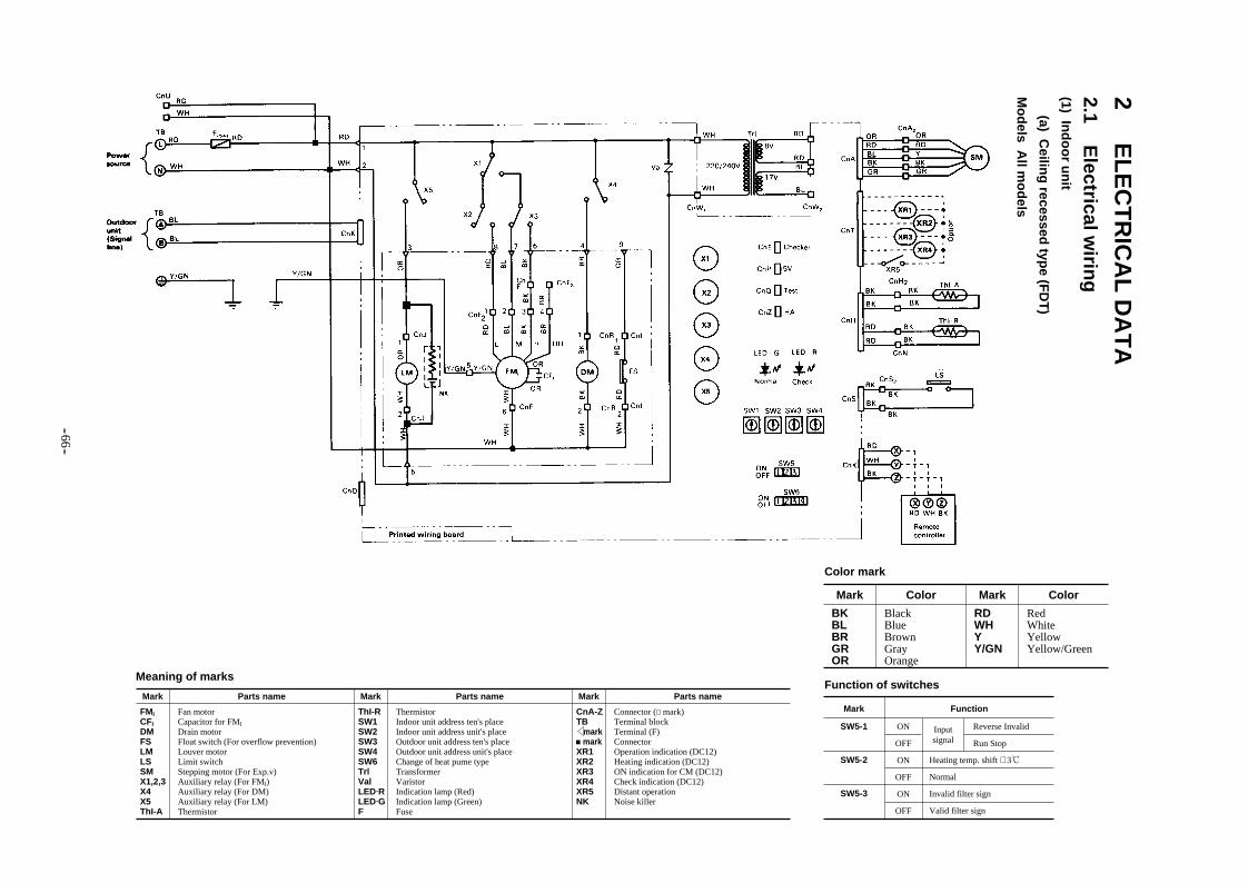
2 EL
EC
TR
ICA
L D
AT
A2.1 E
lectrical wirin
g(1) In
do
or u
nit
(a) Ceilin
g recessed
type (F
DT
)
Mo
dels A
ll mo
dels
Meaning of marks
Mark Parts name Mark Parts name Mark Parts name
FMICFIDMFSLMLSSMX1,2,3X4X5ThI-A
Fan motorCapacitor for FMI
Drain motorFloat switch (For overflow prevention)Louver motorLimit switchStepping motor (For Exp.v)Auxiliary relay (For FMI)Auxiliary relay (For DM)Auxiliary relay (For LM)Thermistor
ThI-RSW1SW2SW3SW4SW6TrlValLED RLED GF
ThermistorIndoor unit address ten's placeIndoor unit address unit's placeOutdoor unit address ten's placeOutdoor unit address unit's placeChange of heat pume typeTransformerVaristorIndication lamp (Red)Indication lamp (Green)Fuse
CnA-ZTB mark markXR1XR2XR3XR4XR5NK
Connector ( mark)Terminal blockTerminal (F)ConnectorOperation indication (DC12)Heating indication (DC12)ON indication for CM (DC12)Check indication (DC12)Distant operationNoise killer
Function of switches
Mark Function
SW5-1 ON
OFF
ON
OFF
ON
OFF
Reverse Invalid
Run Stop
Inputsignal
Heating temp. shift + 3
Normal
Invalid filter sign
Valid filter sign
SW5-2
SW5-3
Mark Color
BKBLBRGROR
BlackBlueBrownGrayOrange
Mark Color
RDWHYY/GN
RedWhiteYellowYellow/Green
Color mark
-- 66 --
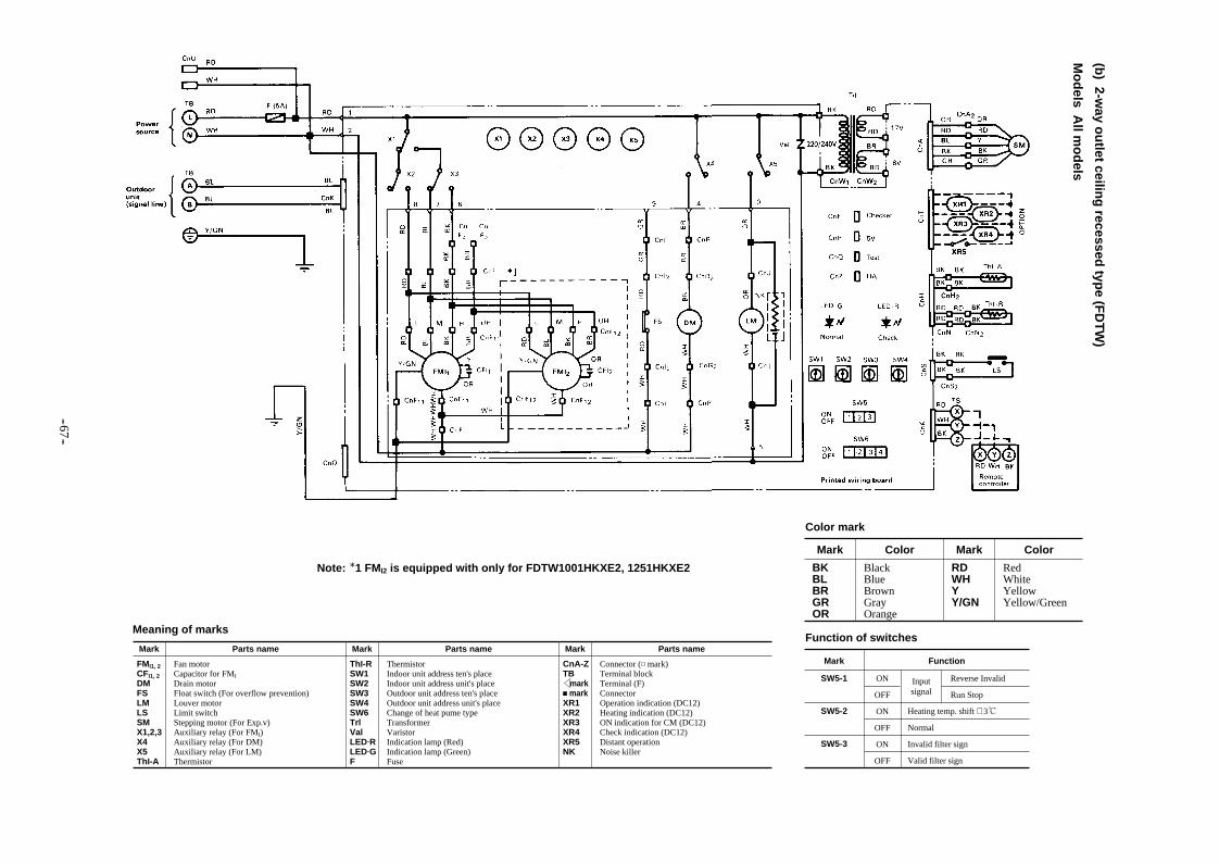
(b) 2-w
ay ou
tlet ceiling
recessed typ
e (FD
TW
)
Mo
dels A
ll mo
dels
Meaning of marks
Note: 1 FMI2 is equipped with only for FDTW1001HKXE2, 1251HKXE2
Mark Parts name Mark Parts name Mark Parts name
FMI1, 2CFI1, 2DMFSLMLSSMX1,2,3X4X5ThI-A
Fan motorCapacitor for FMI
Drain motorFloat switch (For overflow prevention)Louver motorLimit switchStepping motor (For Exp.v)Auxiliary relay (For FMI)Auxiliary relay (For DM)Auxiliary relay (For LM)Thermistor
ThI-RSW1SW2SW3SW4SW6TrlValLED RLED GF
ThermistorIndoor unit address ten's placeIndoor unit address unit's placeOutdoor unit address ten's placeOutdoor unit address unit's placeChange of heat pume typeTransformerVaristorIndication lamp (Red)Indication lamp (Green)Fuse
CnA-ZTB mark markXR1XR2XR3XR4XR5NK
Connector ( mark)Terminal blockTerminal (F)ConnectorOperation indication (DC12)Heating indication (DC12)ON indication for CM (DC12)Check indication (DC12)Distant operationNoise killer
Function of switches
Mark Function
SW5-1 ON
OFF
ON
OFF
ON
OFF
Reverse Invalid
Run Stop
Inputsignal
Heating temp. shift + 3
Normal
Invalid filter sign
Valid filter sign
SW5-2
SW5-3
Mark Color
BKBLBRGROR
BlackBlueBrownGrayOrange
Mark Color
RDWHYY/GN
RedWhiteYellowYellow/Green
Color mark
-- 67 --

Meaning of marks
Mark Parts name Mark Parts name Mark Parts name
FMI1-249FICFI1-2DMFSLMLSSMX1,2,3X4X5
Fan motorInternal thermostat for FMI
Capacitor for FMI
Drain motorFloat switch (For overflow prevention)Louver motorLimit switchStepping motor (For Exp.v)Auxiliary relay (For FMI)Auxiliary relay (For DM)Auxiliary relay (For LM)
ThI-AThI-RSW1SW2SW3SW4SW6TrlValLED RLED G
ThermistorThermistorIndoor unit address ten's placeIndoor unit address unit's placeOutdoor unit address ten's placeOutdoor unit address unit's placeChange of heat pume typeTransformerVaristorIndication lamp (Red)Indication lamp (Green)
FCnA-ZTB mark markXR1XR2XR3XR4XR5
FuseConnector ( mark)Terminal blockTerminal (F)ConnectorOperation indication (DC12)Heating indication (DC12)ON indication for CM (DC12)Check indication (DC12)Distant operation
Function of switches
Mark Function
SW5-1 ON
OFF
ON
OFF
ON
OFF
Reverse Invalid
Run Stop
Inputsignal
Heating temp. shift + 3
Normal
Invalid filter sign
Valid filter sign
SW5-2
SW5-3
Mark Color
BKBLBRGROR
BlackBlueBrownGrayOrange
Mark Color
RDWHYY/GN
RedWhiteYellowYellow/Green
Color mark
(c) 1-way o
utlet ceilin
g recessed
type (F
DT
S)
Mo
dels A
ll mo
dels
Note: 1 FMI2 is equipped with only for FDTS631HKXE2
-- 68 --

(d) C
assetteria type (F
DR
)
Mo
dels A
ll mo
dels
Meaning of marks
Note: 1 FMI2 is equipped with only for FDR1001HKXE2, 1251HKXE2
Mark Parts name Mark Parts name Mark Parts name
FMI1, 2CFI1, 2DMFSSMX1,2,3X449FIThI-A
Fan motorCapacitor for FMI
Drain motorFloat switch (For overflow prevention)Stepping motor (For Exp.v)Auxiliary relay (For FMI)Auxiliary relay (For DM)Internal thermostat for FMI
Thermistor
ThI-RSW1SW2SW3SW4SW6TrlValLED RLED GF
ThermistorIndoor unit address ten's placeIndoor unit address unit's placeOutdoor unit address ten's placeOutdoor unit address unit's placeChange of heat pume typeTransformerVaristorIndication lamp (Red)Indication lamp (Green)Fuse
CnA-ZTB mark markXR1XR2XR3XR4XR5
Connector ( mark)Terminal blockTerminal (F)ConnectorOperation indication (DC12)Heating indication (DC12)ON indication for CM (DC12)Check indication (DC12)Distant operation
Function of switches
Mark Function
SW5-1 ON
OFF
ON
OFF
ON
OFF
Reverse Invalid
Run Stop
Inputsignal
Heating temp. shift + 3
Normal
Invalid filter sign
Valid filter sign
SW5-2
SW5-3
Mark Color
BKBLBRGROR
BlackBlueBrownGrayOrange
Mark Color
RDWHYY/GN
RedWhiteYellowYellow/Green
Color mark
-- 69 --
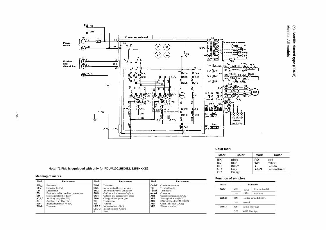
(e) Satellie d
ucted
type (F
DU
M)
Mo
dels A
ll mo
dels
Meaning of marks
Note: 1 FMI2 is equipped with only for FDUM1001HKXE2, 1251HKXE2
Mark Parts name Mark Parts name Mark Parts name
FMI1,2CFI1,2DMFSSMX1,2,3X449FIThI-A
Fan motorCapacitor for FMI
Drain motorFloat switch (For overflow prevention)Stepping motor (For Exp.v)Auxiliary relay (For FMI)Auxiliary relay (For DM)Internal thermostat for FMI
Thermistor
ThI-RSW1SW2SW3SW4SW6TrlValLED RLED GF
ThermistorIndoor unit address ten's placeIndoor unit address unit's placeOutdoor unit address ten's placeOutdoor unit address unit's placeChange of heat pume typeTransformerVaristorIndication lamp (Red)Indication lamp (Green)Fuse
CnA-ZTB mark markXR1XR2XR3XR4XR5
Connector ( mark)Terminal blockTerminal (F)ConnectorOperation indication (DC12)Heating indication (DC12)ON indication for CM (DC12)Check indication (DC12)Distant operation
Function of switches
Mark Function
SW5-1 ON
OFF
ON
OFF
ON
OFF
Reverse Invalid
Run Stop
Inputsignal
Heating temp. shift + 3
Normal
Invalid filter sign
Valid filter sign
SW5-2
SW5-3
Mark Color
BKBLBRGROR
BlackBlueBrownGrayOrange
Mark Color
RDWHYY/GN
RedWhiteYellowYellow/Green
Color mark
-- 70 --
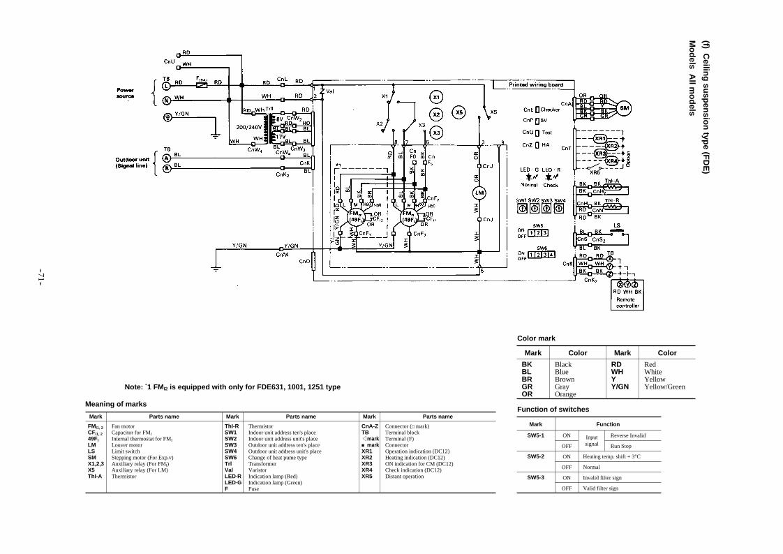
(f) Ceilin
g su
spen
sion
type (F
DE
)
Mo
dels A
ll mo
dels
Meaning of marks
Note: *1 FMI2 is equipped with only for FDE631, 1001, 1251 type
Mark Parts name Mark Parts name Mark Parts name
FMI1, 2CFI1, 249FILMLSSMX1,2,3X5ThI-A
Fan motorCapacitor for FMI
Internal thermostat for FMI
Louver motorLimit switchStepping motor (For Exp.v)Auxiliary relay (For FMI)Auxiliary relay (For LM)Thermistor
ThI-RSW1SW2SW3SW4SW6TrlValLED·RLED·GF
ThermistorIndoor unit address ten's placeIndoor unit address unit's placeOutdoor unit address ten's placeOutdoor unit address unit's placeChange of heat pume typeTransformerVaristorIndication lamp (Red)Indication lamp (Green)Fuse
CnA-ZTB mark markXR1XR2XR3XR4XR5
Connector ( mark)Terminal blockTerminal (F)ConnectorOperation indication (DC12)Heating indication (DC12)ON indication for CM (DC12)Check indication (DC12)Distant operation
Function of switches
Mark Function
SW5-1 ON
OFF
ON
OFF
ON
OFF
Reverse Invalid
Run Stop
Inputsignal
Heating temp. shift + 3°C
Normal
Invalid filter sign
Valid filter sign
SW5-2
SW5-3
Mark Color
BKBLBRGROR
BlackBlueBrownGrayOrange
Mark Color
RDWHYY/GN
RedWhiteYellowYellow/Green
Color mark
-- 71 --

(g) W
all mo
un
ted typ
e (FD
KY
)
Mo
dels A
ll mo
dels
Meaning of marks
Mark Parts name Mark Parts name Mark Parts name
FMI1, 2CFI1, 249FILMLSSMX1,2,3X5ThI-A
Fan motorCapacitor for FMI
Internal thermostat for FMI
Louver motorLimit switchStepping motor (For Exp.v)Auxiliary relay (For FMI)Auxiliary relay (For LM)Thermistor
ThI-RSW1SW2SW3SW4SW6TrlValLED·RLED·GF
ThermistorIndoor unit address ten's placeIndoor unit address unit's placeOutdoor unit address ten's placeOutdoor unit address unit's placeChange of heat pume typeTransformerVaristorIndication lamp (Red)Indication lamp (Green)Fuse
CnA-ZTB mark markXR1XR2XR3XR4XR5
Connector ( mark)Terminal blockTerminal (F)ConnectorOperation indication (DC12)Heating indication (DC12)ON indication for CM (DC12)Check indication (DC12)Distant operation
Function of switches
Mark Function
SW5-1 ON
OFF
ON
OFF
ON
OFF
Reverse Invalid
Run Stop
Inputsignal
Heating temp. shift + 3°C
Normal
Invalid filter sign
Valid filter sign
SW5-2
SW5-3
Mark Color
BKBLBRGROR
BlackBlueBrownGrayOrange
Mark Color
RDWHYY/GN
RedWhiteYellowYellow/Green
Color mark
-- 72 --

(h) F
loo
r stand
ing
type (F
DF
L)
Mo
dels A
ll mo
dels
Meaning of marks
Mark Parts name Mark Parts name Mark Parts name
FMICFI49FISMX1,2,3ThI-AThI-RSW1SW2
Fan motorCapacitor for FMI
Internal thermostat for FMI
Stepping motor (For Exp.v)Auxiliary relay (For FMI)ThermistorThermistorIndoor unit address ten's placeIndoor unit address unit's place
SW3SW4SW6TrlValLED·RLED·GF
Outdoor unit address ten's placeOutdoor unit address unit's placeChange of heat pume typeTransformerVaristorIndication lamp (Red)Indication lamp (Green)Fuse
CnA-ZTB mark markXR1XR2XR3XR4XR5
Connector ( mark)Terminal blockTerminal (F)ConnectorOperation indication (DC12)Heating indication (DC12)ON indication for CM (DC12)Check indication (DC12)Distant operation
Function of switches
Mark Function
SW5-1 ON
OFF
ON
OFF
ON
OFF
Reverse Invalid
Run Stop
Inputsignal
Heating temp. shift + 3°C
Normal
Invalid filter sign
Valid filter sign
SW5-2
SW5-3
Mark Color
BKBLGROR
BlackBlueGrayOrange
Mark Color
RDWHYY/GN
RedWhiteYellowYellow/Green
Color mark
-- 73 --

(2) Individual flow divide controller
Power source1 phase 220/240V 50Hz
Power source(between indoor unit)
SVH
SVC
SVL
SVG
XR, X1, XR1
XH, X2, XR2
XR3
XR4
• Meaning of marks
-- 74 --
Note (1) This illustration shows the circuit diagram for when 1 indoor unit is connected with a central flow divide controller and relay kit (flow divide controller accessory).
(2) “.......” denotes the local wiring.(3) The option shows when a remote start/stop and monitoring kit is
connected.
High-pressure gas solenoid valve
Low-pressure gas solenoid valve
Liquid solenoid valve
Bypass solenoid valve
Operation output
Heat output
Thermal ON output
Inspection output

(3) Ou
tdo
or u
nit
FD
C2001H
KX
RE
2, 2501HK
XR
E2
Meaning of marks
Mark Parts name Mark Parts name Mark Parts name
CMFM1,2IM52C49F1,2CHCF1,2X1X2X3X4X7X8~10X11X12X13X14X2020SS
Compressor motorFan motor (outdoor unit)Motor for cooling inverterMagnetic contactor for CMInternal thermostat for FMoCrankcase heaterCapacitor for FMoAuxiliary relay (for 52C)Auxiliary relay (for 20SS)Auxiliary relay (for 20SL)Auxiliary relay (for SV1)Auxiliary relay (for 20VF, 20VU)Auxiliary relay (for FMo1)Auxiliary relay (for FMo2)Auxiliary relay (for SVS)Auxiliary relay (for SVL)Auxiliary relay (for SV2)Auxiliary relay (for SV3)4way valve (front heat exchanger)
20SL20VF20VUSV1SV2SV3SVSSVL63H163H263H363H463LTho-ATho-CTho-DTho-RCT1,2NR
4way valve (rear heat exchanger)Solenoid valve (full)Solenoid valve (partial)Solenoid valve (compressor cooling)Solenoid valve (excessive cooling heat exchanger by-pass)Solenoid valve (discharge gas by-pass)Solenoid valve (for front heat exchanger stoppage)SOlenoid valve (rear heat exchanger stoppage)High Pressure switch (for protection)High Pressure switch (for control)High Pressure switch (high pressure control)High Pressure switch (high pressure control)Low Pressure switch (low pressure control)Thermistor (outdoor air temp)Thermistor (dome temp)Thermistor (discharge temp)Thermistor (outdoor H.X. temp)Current sensorNoise killer
SKSATrVa1,2,3,4TB1,2FCnA~YSW1SW2SW3-1SW3-2SW3-3LED1LED2LED3-5LD1LD2-4
Spark killerArrestorTransformerVaristorTerminal blockFuseConnector ( mark)Unit No.10 rank of outdoor unitUnit No.1 rank of outdoor unitL.E.D. resetDefrost changePrevention of snow accumulationIndication lamp (red)Indication lamp (Green)Indication lamp (Yellow)Indication lamp (Green)Indication lamp (red)
Function of switches
Mark Function
SW3-4 ON
OFF
ON
OFF
ON
OFF
ON
OFF
Trial operation
Regular operation
Cooling trial operation
Heating trial operation
Compulsory operation
Regular operation
Test mode
Regular operation
SW3-5
SW3-6
SW3-7
Mark Color
BKBLBRGNGR
BlackBlueBrownGreenGray
Mark Color
ORRDWHYY/GN
OrangeRedWhiteYellowYellow/green
Color markNotes (1) “.......” denotes the local wiring.
(2) and of TB2 are the signalwire terminal blocks (5V).
(3) Use 0.75 to 2mm2 × 2 core wire for the indoor andoutdoor connection signal wire.
(4) The signal wiring shall be separate from the powesupply wiring.
-- 75 --

Refrigerant piping [1/3] [2/3] [3/3]
Refrigerant piping

3. APPLICATION DATA 3.1 Refrigerant Piping
Refrigerant piping size selection table
-- 76--
Liquid piping
Outdoor unitconnection pipe Downstream indoor
unit capacity total (1)
FDC2001type
Branch lineIndoor unit
connection pipe
modelsIndoorside
Outdoorside
Flow divide controllerconnection pipe
FDC2501type
160 or more
160 or less 90 or more
201, 251321, 401
type
501,631,801type
1001, 1251 type90 or less
Intake gas piping
Dischargegas piping
φ12.7 × 1.0 mm
φ25.4 × 1.2 mm
φ19.05 × 1.0 mm
φ12.7 × 1.0 mm
φ28.58 × 1.4 mm
φ19.05 × 1.0 mm
φ12.7 × 1.0 mm
φ25.4 × 1.2 mm
φ19.05 × 1.0 mm
φ9.52 × 0.8mm
φ19.05 × 1.0mm
φ15.88 × 1.0 mm
φ9.52 × 0.8mm
φ15.88 × 1.0mm
φ12.7 × 1.0 mm
φ15.88 × 1.0mm
φ12.7 × 1.0 mm
φ6.35 × 0.8mm
φ12.7 × 1.0mm
φ9.52 × 0.8mm
φ15.88 × 1.0mm
φ9.52 × 0.8mm
φ9.52 × 0.8mm
φ9.52 × 0.8mm
φ19.05 × 1.0mm
φ15.88 × 1.0mm
Note (1) This shows the total capacity of the indoor units connected after indicated branch pipe. (2) 1 flow divider pipe set is required for each division.
Note (1) Each flow divider pipe is
surrounded with insulation.
(2) Each pipe is cut off in the
middle of the diameter that is
used in that locality.
Branch pipe set part shapes
Symbol Name
Branch pipe
Reducer
Part shape Quantity
1
Remarks
Intake gas piping
1 Discharge gas piping
1 Liquid piping
1 Intake gas piping(FDC2501HKXRE2)
Shapes of individual flow divide controller accessories
Code A B C
Name Reducer Strainer coupline In Sulation
Application
Quantity
Shape
For outdoordischarge gas piping
For outdoor intakeand indoor gas piping
For outdoor andindoor liquid piping
For outdoor discharge gas piping
21 2 1
For pipe cover
Piping connection
Relay kit
For controller
Number of divisions
1
2
3
A

Use reducer A and process the φ12.7 portion into a flare.
Cut off reducer B using a pipe cutter as shown in the illustration and make a flare.
Process the included reducer as illustrated below.Use the flare nuts included with the individual flow divide controller.
Example of piping
[Total capacity: 312 (34800w)]
Outdoor unit: FDC2501HKXRE2 Indoor unit: Combination of 6 units
When the indoor unit capacity is 90 or more
When the indoor unit capacity is 50 or less
Piping connection instructions (for the above example)
Individual flow divide controller: HPHD01R-E × 6 setsBranch pipe set: DIS-1KXR3-E × 5 sets ( )
( OD12.7 → ID15.88 )
Cut off reducer B using a pipe cutter as shown in the illustration and make a flare.
( OD15.88 → ID12.7 )
( OD15.88 → ID19.88 )
Outdoor unit
Indoor unit
Individual flowdivide controller
Intake gas main pipingφ25.58
Discharge gas main pipingφ19.05
Liquid main pipingφ12.7
Reducer
A type
B type
B type
ID15.88 (Brazing)
Reducer B (accessory)
ID19.05 (Brazing)
ID19.05 (Brazing)
Reducer B (accessory)
Reducer C (accessory)
ID12.7 (Brazing)
ID6.35 (Brazing)ID12.7 (Brazing)
ID6.35 (Brazing)
-- 77--

-- 78--
When the outdoor unit are installed at a higher level than the individual flow divide controller and a vertical flow divider is required for the piping connections of 2 or more individual flow divide controllers for 1 module, use the "flow divider pipe set" for vertical divides. Flow divider pipe set for vertical divides Part No. DIS-V1KXR3-E
Note (1) Insulation is provided to all flow divider pipes.
(2) Cut off the flow divider pipes in the center to match the diameter of the piping used on site.
Shapes of accessory parts for brunch pipe set for vertical divides
1
2
3
Classifi-cation
Inta
ke g
as p
ipin
g
Inta
ke g
as p
ipin
g
Dis
char
ge
gas
pip
ing
Liq
uid
pip
ing
Symbol Branch pipe
—
—
Classifi-cation Symbol Branch pipe
Reference 1: Be sure to install the vertical flow divider coupling (both) for gas and liquid) as "vertical divide" as illustrated below.

(1)Precaution in electric wiring
(2)Wiring system Diagram [1/2] [2/2]
(3)Indoor and outdoor signal wiring
(4)Remote controller wiring
Electric wiring

(1) Precaution in electric wiring.
(2) Wiring system Diagram
(a) Use separate power supplies for the outdoor and indoor units respectiveliy (Standard specification)
(b) Signal wiring (for indoor and outdoor units)
When No. 4 shielding wire is used, always ground the single wire side of the shielding wire . In addition, using the shielding
wire is helpful to prevent the incorrect connection between 5V DC and 220/240V or 380/415V AC because the
discrimination from the power supply wire is clear.
Double-core cable with a diameter 0.75 to 2 mm2 should be used for the signal wires.
Never make the indoor and outdoor connecting signal line use “co-axial cable” or “strand” with the power wiring for indoor and outdoor unit and other ower line.
(Never use a multiconductor wire together with power line. It may cause erroneous operation.)
Do not connect high voltage wires 220/240 V or 380/415 V to signal wires. as these wires are DC 5V. Signal wires should be
connected so that the terminal Nos. conform with each other for between outdoor and between indoor units. However, they
will work properly if different polarities are connected.
(Connect (A) and (A), (B)and (B).)
Do not strand or run the remote control cord with power line, electric line, etc. The total length of the signal wires Should be 1000m or less.
Recommended signal wire list
No.
1
2
3
4
Vinyl cabtire round cord
Vinyl cabtire round cable
Control vinyl insulated, vinyl sheathed cable
Shielding wire
Name
VCTF double-core 0.75 to 2 mm2
VCT double-core 0.75 to 2 mm2
CVV double-core 0.75 to 2 mm2
MVVS double-core 0.75 to 2 mm2
Symbol
3.2 Electric wiring
-- 79 --
Power source (outdoor unit side)
Power source (indoor unit side)
1-Phase 220/240V 50Hz
3-Phase 380/415V 50Hz
Earth leakagebreaker
Circult breaker
Earth leakagebreaker
Circult breaker
Power source wire[Individual flow divide controller accessory wire (2m)]
Individual flow divide controller accessory wire (2m)
Relay kit (Individual flow divide controller accessory)
Signal wire (between indoor units)
IndoorUnit
Signal wire [Relay kit accessory (2m)]
Remotecontrol
Outdoor Unit
Signal wire (between outdoor and indoor unit)
Individual flow divide controllor

Do not connect high voltage wire 380/415V to signal wires, as these wires are DC 5V. Signal wires should be connected so that
the terminal Nos. conform with each other for between outdoor and between indoor units. However, they will work properly if
different polarities are connected. (Connect (A) and (A), (B) and (B).)
– 80 –
Outdoor/Indoor units connection procedures
Signal wire
Power source (indoor unit side)
Individual flowdivide controllor
To next units by turn
Indoor unit
Remote control wire
Signal wire [Relay kit accessory (2m)]
Relay kit(Individual flow divide controller acessory)
Individual flow divide controller accessory wire (2m)
Power source wire[Individual flow divide controller accessory wire (2m)
Signal wire (between indoor unit)
Outdoor unit

(3) Indoor and outdoor signal wiring
(a) If only one Outdoor unit is used
(b) If plural outdoor units are used
1) A maximum of 48 indoor units can be connected by using the crossover wiring method, with 2 wires for each side of the outdoor and indoor units.
2) Indoor/outdoor wiring method for multiple floors.
3) Loop wiring is inhibited
Notes (1) The indoor and outdoor signal wiring are without polarity
(2) For connection to the terminal block, use as M3.5 (5/32) round eye-let terminal is shown below.
Either of the above wiring is correct.
-- 81--

(4) Remote controller wiring
(a) Wiring for controlling only one indoor unit.
Note (1) Cables for the remote controller have polarity. Be sure to connect terminal blocks with the same numbers. If mis wiring occurs, E1 is displayed and disables the unit operating.
(b) When controlling plural units.
Allowable rang of wire thickness and length
Standard Within
1) Use the same procedure shown in the drawing above for the wiring of the power supply, both indoor and outdoor units and
remote controller
When the wiring length for the remote controller exceeds 100 m, use the wiring procedure shown in the drawing below.
2) Connect each of the indoor units for group controlling (3 cables)
3) When there is more than one outdoor unit, they can be controlled by one Remote controller.
4) One remote controller is capable of controlling up to 16 units in group.
a) Connect the cables to the terminal blocks of X, Y, and Z for the indoor unit remote controller. Since the cables have polarity,
be sure to connect them to terminal blocks with the same numbers.
b) Use cables of more than 0.5 mm2 (Flexible and easily moved)
c) The total length of cables for crossover connection and the remote controller should be less than 600 m.
Notes (1) Use shielded cables, when wiring in parallel with cables for other power supply or when there is a possibility of
being affected by outer noise such as noise from a high-frequency unit.
0.3mm2 × Within 100m0.5mm2 × Within 200m0.75mm2 × Within 300m 1.25mm2 × Within 400m 2mm2 × Within 600m
-- 82--