knx система домашней автоматизации
DESCRIPTION
ÂTRANSCRIPT

BUILDING AUTOMATION
BUILDINGAUTOMATION
BU
ILD
ING
AU
TO
MA
TIO
N
BUILDING AUTOMATION
BUILDINGAUTOMATION
BU
ILD
ING
AU
TO
MA
TIO
N
BUILDING AUTOMATION
Specialist catalogue


1
Products, systems and solutions to control electrical energy, safety and communication: Vimar group does this and much more, ensuring continual improvement for every lifestyle. All of which is made in Italy to combine design and technology in terms of complete reliability and well-being. A range of residential series offering a wide variety of combinations in terms of design, materials and types of controls; Home Automation and Building Automation systems; numerous solutions for smart and secure management of video door entry, CCTV and automated access devices. This is what the Vimar group offers. An offering that reflects a long history built on tradition, expertise, commitment and passion for a chosen line of work.
Vimar group: positive energy for highly developed systems.

Vimar Group. The five points of excellence.
The heart of the company - where we devise, design and produce products - is still located in the north-east of Italy, because we believe in the Made in Italy in all its forms. Our products are inspired by a truly unique combination of high quality aesthetics and reliable technology. From materials and design to electronic processing, we distinguish ourselves through a renowned style that speaks our language throughout the world.
MADE IN ITALY
We believe that the quality of our products is their best calling card, and this is why we test our products one by one. We are proud of our ownership of the most important quality certifications to UNI EN ISO 9001:2008; our environmental management system is certified to the UNI EN ISO 14001:2004 standard, without forgetting health and safety, with our work environment certified to the BS OHSAS 18001:2007 standards.
HIGH QUALITY
2

We invest 6% of our annual turnover in Research and Development, to ensure we always offer the very best in terms of technology and design. Over the years we have registered over 150 patents around the world that testify to the equal attention we devote to major innovation and the smaller details that guarantee the safety of simple everyday actions.
RESEARCH AND DEVELOPMENT
The correct waste material separation ensures the product designed at the outset of being totally dismantled and recycled at the end of its life. Thanks to the water based and UV-cross linked painting we reduce atmospheric emissions of VOCs (Volatile Organic Compounds) lower than the limits set out by the strictest European standards and galvanic bath treatment is replaced with the innovative and greener MSD (Magnetron Sputtering Deposition) treatment. The packaging is made of recycled materials and printed with water-based inks with no harmful substances and with ecological glues.
ENVIRONMENT
We have given shape and life to ideas in order to ensure continual improvement in every lifestyle. Today, for the all-round management of electrical systems, we have a complete range of products: wiring devices, home & building automation systems, video door entry and CCTV and gate automation systems, plugs, socket outlets and accessories. Over 9,000 items in the catalogue that combine aesthetic quality, technological reliability and ease of installation to bring them home to all our customers.
WE IMPLEMENT IDEAS
3

The universe of Vimar group solutions.For large or small residential, commercial buildings or hospitality facilities, clinics or yachts, we have developed solutions that dialogue with each other, while maintaining their own specificity: technologically advanced
Wiring devices
Eikon Arké
Home automation
AESTHETIC AND FUNCTIONAL SOLUTIONS
HOME AUTOMATION SYSTEM
4
Plana

functions and systems, which are explained in dedicated catalogues, complement each other with perfect aesthetic coordination to manage any building in the best way possible.
CCTVAutomation systems
Building automation
Video door entry
AUTOMATION SYSTEMS
SOLUTIONS FOR ACCESS AND VIDEO CONTROL
5

Solutions for conventional systems
Solutions for thermoregulation and energy management: thermostats and time-thermostats to manage remotely the temperature of the house and view consumption for energy savings.
A complete sound system, compati-ble with MP3 players, iPod and iPhone too, it can be installed in con-ventional systems.
TEMPERATURE ANDENERGY MANAGEMENT
SOUND SYSTEM
CONTROLS
For any aesthetic and functional need: touch, axial, rocker, infrared, and radio-frequency.
ACCESS CONTROL
Transponder and smart card readers to control entry and restrict access to certain rooms.
A useful summary table to guide you through the solutions for conventional systems. A wide range of functions for any installation requirement, spelled out in a series of preferential applications. Whatever your need Vimar Group always offers the best solution.
1.CONTROLS
2.TEMPERATURE AND ENERGY
MANAGEMENT
3.LIGHTING
4. EMERGENCY
LIGHTING
5.POWER AND
SIGNAL SOCKET OUTLETS
6.SOUND SYSTEM
7.ACCESS
CONTROL
8.PLUGS AND SOCKETS
9.VIDEO DOOR
ENTRY
10.CCTV
11.GATE
AUTOMATION
SMALL RESIDENTIAL BUILDINGS(Small and medium-sized residential units, semi-detached houses and apartments)
LARGE RESIDENTIAL BUILDINGS(Large residential units, detached houses and lofts)
COMMERCIAL BUILDINGS(Small and medium-sized commercial units, shops and offices)
HOTEL BUILDINGS(Small and medium-sized hotel units, B&Bs, hotels, etc.)
SCHOOL BUILDINGS(Small and medium-sized school units, infant schools, elementary schools, etc.)
HEALTH CARE FACILITIES
SHIPS AND YACHTS(Small boats, ships and yachts)
Preferential applications.
VIDEO DOOR ENTRY
Solutions for video door entry system with a wide range of indoor units, entrance panels and controls for landing calls, to suit any building and simplify communication.
6
1
7
2
6 98
A complete system of plugs, socket outlets multiple sockets for simple and professional purposes, adaptors, exten-sion cords and cable reels.
PLUGS AND SOCKETS

1.CONTROLS
2.TEMPERATURE AND ENERGY
MANAGEMENT
3.LIGHTING
4. EMERGENCY
LIGHTING
5.POWER AND
SIGNAL SOCKET OUTLETS
6.SOUND SYSTEM
7.ACCESS
CONTROL
8.PLUGS AND SOCKETS
9.VIDEO DOOR
ENTRY
10.CCTV
11.GATE
AUTOMATION
SMALL RESIDENTIAL BUILDINGS(Small and medium-sized residential units, semi-detached houses and apartments)
LARGE RESIDENTIAL BUILDINGS(Large residential units, detached houses and lofts)
COMMERCIAL BUILDINGS(Small and medium-sized commercial units, shops and offices)
HOTEL BUILDINGS(Small and medium-sized hotel units, B&Bs, hotels, etc.)
SCHOOL BUILDINGS(Small and medium-sized school units, infant schools, elementary schools, etc.)
HEALTH CARE FACILITIES
SHIPS AND YACHTS(Small boats, ships and yachts)
GATE AUTOMATION
Socket outlets, connectors and devices for transmitting data, vide-os and images inside and outside the building.
Controls, socket outlets and cover plates with antibacterial treatment to ensure the utmost hygiene in public facilities.
Specific solutions guaranteed to manage any access and control sliding gates, swing gates, garage doors, doors and windows and barriers.
CCTV
Solutions for video surveillance: cameras with analog, analog PRO, HD-SDI and IP technologies, DVR, NVR video recorders and accessories.
NETSAFESTRUCTURED CABLING
12.STRUCTURED
CABLING
13.ANTIBACTERIAL
DEVICES
LIGHTING EMERGENCY LIGHTING
Control devices for every type of source (halogen, CFL, LED) and for managing flush-mounted RGB lamps.
Emergency LED lighting devices with 1 or 3 modules, can be flush mounted, necessary in a black-out or as step lights.
ANTIBACTERIAL DEVICES
7
10 11 12 13
3 4 5
POWER AND SIGNALSOCKET OUTLETS
Devices to provide energy, from Italian and international standard power socket outlets, with SICURY protective shutter, to the power supply unit with USB socket.

CONTROL
Sophisticated technology that controls all the functions of the dwelling both centrally by a single control device and room by room via local devices, over the Internet with PCs, tablets and smart-phones of the latest generation.
The By-me home automation system offers four areas of application with a wide range of functions and can be deployed alongside other specific systems, giving added value to your project. See the summary table to check the versatility of our home automation solutions.
Automation solutions for the home and small business sectors.
COMFORT
Lighting, scenarios, sound system, moving curtains or roller shutters: each room in the home is an oasis of well-being where you can find the comfortable conditions you prefer.
Temperature control, management of energy consumptions, water and gas are optimized with innovative technology that optimizes energy efficiency, reducing waste.
ENERGY EFFICIENCYSECURITY/
SAFETY
Total protection guaranteed on the outside by burglar alarm system, video surveillance, access control and video door entry systems and on the inside by sensors that detect and promptly report any gas leaks or flooding.
BY-MEVIDEO DOOR ENTRY CCTV GATE AUTOMATION NETSAFE
CONTROL COMFORT ENERGY EFFICIENCY SECURITY/SAFETY
RESIDENTIAL BUILDINGS(Small and medium-sized residential units, semi-detached houses and apartments)
COMMERCIAL BUILDINGS(Small and medium-sized commercial units: offices, shops, etc.)
HOTEL BUILDINGS(Small and medium-sized hotel units: hotels, B&Bs, etc.)
PUBLIC BUILDINGS(Small and medium-sized school units: infant schools, elementary schools, churches, gymnasiums, etc.)
HEALTH CARE FACILITIES(Small and medium-sized health care units: nursing homes, convalescent homes, etc.)
SHIPS AND YACHTS(Small boats)
Preferential applications.
8

Socket outlets, connectors and devices for transmitting data, videos and images inside and outside the building.
Solutions for video door entry system with a wide range of indoor units, entrance panels and controls for landing calls, to suit any building and simplify communication.
Solutions for video surveillance: cameras with analog, analog PRO, HD-SDI and IP technologies, DVR, NVR video recorders and accessories.
STRUCTURED CABLING
VIDEO DOOR ENTRY CCTV GATE AUTOMATION
BY-MEVIDEO DOOR ENTRY CCTV GATE AUTOMATION NETSAFE
CONTROL COMFORT ENERGY EFFICIENCY SECURITY/SAFETY
RESIDENTIAL BUILDINGS(Small and medium-sized residential units, semi-detached houses and apartments)
COMMERCIAL BUILDINGS(Small and medium-sized commercial units: offices, shops, etc.)
HOTEL BUILDINGS(Small and medium-sized hotel units: hotels, B&Bs, etc.)
PUBLIC BUILDINGS(Small and medium-sized school units: infant schools, elementary schools, churches, gymnasiums, etc.)
HEALTH CARE FACILITIES(Small and medium-sized health care units: nursing homes, convalescent homes, etc.)
SHIPS AND YACHTS(Small boats)
9
Specific solutions guaranteed to manage any access and control sliding gates, swing gates, garage doors, doors and windows and barriers.
CONTROL
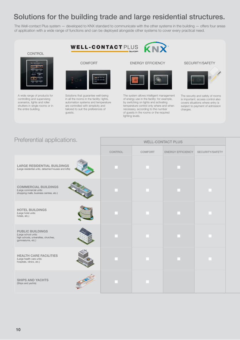
A wide range of products for controlling and supervising scenarios, lights and roller shutters in single rooms or in the entire building.
The Well-contact Plus system — developed to KNX standard to communicate with the other systems in the building — offers four areas of application with a wide range of functions and can be deployed alongside other systems to cover every practical need.
Solutions for the building trade and large residential structures.
COMFORT
Solutions that guarantee well-being in all the rooms in the facility: lights, automation systems and temperature are controlled with simplicity and tailored to suit the preferences of guests.
The system allows intelligent management of energy use in the facility: for example, by switching on lights and activating temperature control only where and when necessary, according to the number of guests in the rooms or the required lighting levels.
ENERGY EFFICIENCY SECURITY/SAFETY
The security and safety of rooms is important: access control also covers situations where entry is subject to payment of admission charges.
WELL-CONTACT PLUSVIDEO DOOR ENTRY CCTV GATE AUTOMATION NETSAFE CALL-WAY
CONTROL COMFORT ENERGY EFFICIENCY SECURITY/SAFETY
LARGE RESIDENTIAL BUILDINGS(Large residential units, detached houses and lofts)
COMMERCIAL BUILDINGS(Large commercial units: shopping malls, business centres, etc.)
HOTEL BUILDINGS(Large hotel units:hotels, etc.)
PUBLIC BUILDINGS(Large school units: high schools, universities, churches, gymnasiums, etc.)
HEALTH CARE FACILITIES(Large health care units: hospitals, clinics, etc.)
SHIPS AND YACHTS(Ships and yachts)
Preferential applications.
10

Use the summary table to find your type of project and you will see that the Vimar offering is truly comprehensive, covering large residential and commercial buildings, and hospitality or healthcare facilities of whatever size.
WELL-CONTACT PLUSVIDEO DOOR ENTRY CCTV GATE AUTOMATION NETSAFE CALL-WAY
CONTROL COMFORT ENERGY EFFICIENCY SECURITY/SAFETY
LARGE RESIDENTIAL BUILDINGS(Large residential units, detached houses and lofts)
COMMERCIAL BUILDINGS(Large commercial units: shopping malls, business centres, etc.)
HOTEL BUILDINGS(Large hotel units:hotels, etc.)
PUBLIC BUILDINGS(Large school units: high schools, universities, churches, gymnasiums, etc.)
HEALTH CARE FACILITIES(Large health care units: hospitals, clinics, etc.)
SHIPS AND YACHTS(Ships and yachts)
Socket outlets, connectors and devices for transmitting data, videos and images inside and outside the building.
Emergency call devices for alerting healthcare staff and monitoring patients, controls, socket outlets and cover plates all finished with antibacterial treatment.
Solutions for video door entry system with a wide range of indoor units, entrance panels and controls for landing calls, to suit any building and simplify communication.
Specific solutions guaranteed to manage any access and control sliding gates, swing gates, garage doors, doors and windows and barriers.
Solutions for video surveillance: cameras with analog, analog PRO, HD-SDI and IP technologies, DVR, NVR video recorders and accessories.
VIDEO DOOR ENTRY CCTV GATE AUTOMATION NETSAFESTRUCTURED
CABLING
CALL-WAYEMERGENCY
CALLS
11

12
BUILDING AUTOMATION
Contents

13
BUILDING AUTOMATION
WELL-CONTACT PLUS from page 14
CALL-WAY from page 112
NETSAFE from page 182
WE
LL-C
ON
TAC
T P
LUS
CA
LL-W
AYN
ETS
AFE
14
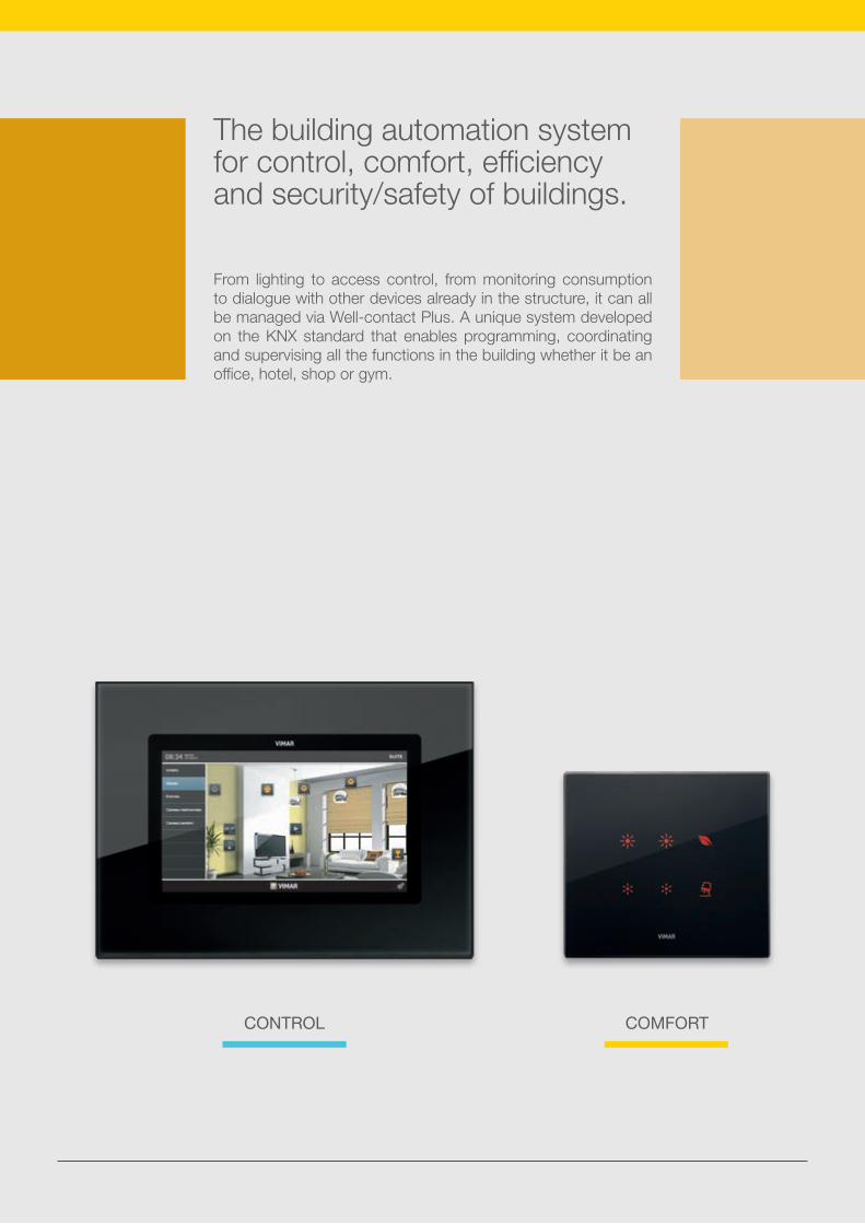
The building automation system for control, comfort, efficiency and security/safety of buildings.
From lighting to access control, from monitoring consumption to dialogue with other devices already in the structure, it can all be managed via Well-contact Plus. A unique system developed on the KNX standard that enables programming, coordinating and supervising all the functions in the building whether it be an office, hotel, shop or gym.
CONTROL COMFORT

15
SECURITY/SAFETYEFFICIENCY

16
Control.
WELL-CONTACT SUITE.
Five different applications, differentiated by the intended use and size of the property, that enable managing and controlling all the devices in the system.
FULL FLAT TOUCH SCREEN.Supervising a room or the entire system via stylish devices featuring intuitive icons.
total supervision room control
Optimized management.
Control and comfort are guaranteed with Well-contact Plus. The system enables centralized management of any structure. Raising and lowering curtains or roller shutters, setting the climate, dosing the lighting, controlling access, but also viewing the images of CCTV cameras. All from a single point.

17
Comfort.
KNX DEVICES FOR AUTOMATION SYSTEMS.
Used for raising / lowering the roller shutters. They are equipped with RGB LEDs with predefined symbols, chosen from a large library.
KNX DEVICES FOR LIGHT CONTROL.
Equipped with 4 independent buttons that can be customised with icons indicating their function.
automation systems lighting
lightingautomation systems
room controlglobal monitoring

18
Energy efficiency.
IR PRESENCE DETECTOR.
Enables switching on lights only when someone is actually present, a perfect combination of functionality and energy saving.
TOUCH THERMOSTAT.
Controls room temperature to assure made-to-measure comfort. Its status can be managed and supervised from reception.
energy management climate control
Full efficiency and security.
These systems are totally integrated which provides real benefits, avoiding unnecessary waste and increasing well-being. The climate can be centrally controlled and can be switched on or off according to whether people are present or windows open. Security is guaranteed by the transponder card readers that permit access to certain areas or rooms only to authorized persons and by the video surveillance system, capable of monitoring the entire structure.

19
Safety and security.
TRANSPONDER READER.
Simply bring the card near to open the electrical lock and turn on the courtesy lights. The reader provides access to different rooms only for authorized persons, ideal for hotels and accommodation facilities.
MULTIMEDIA VIDEO TOUCH SCREEN.
Through integration with the CCTV systems it provides a perfect, high-definition picture of what is happening inside and outside the building.
accesses video surveillance
climate controlenergy management video surveillanceInputs

20
WELL-CONTACT PLUS
Catalogue section
21
WELL-CONTACT PLUS
WE
LL-C
ON
TAC
T P
LUS
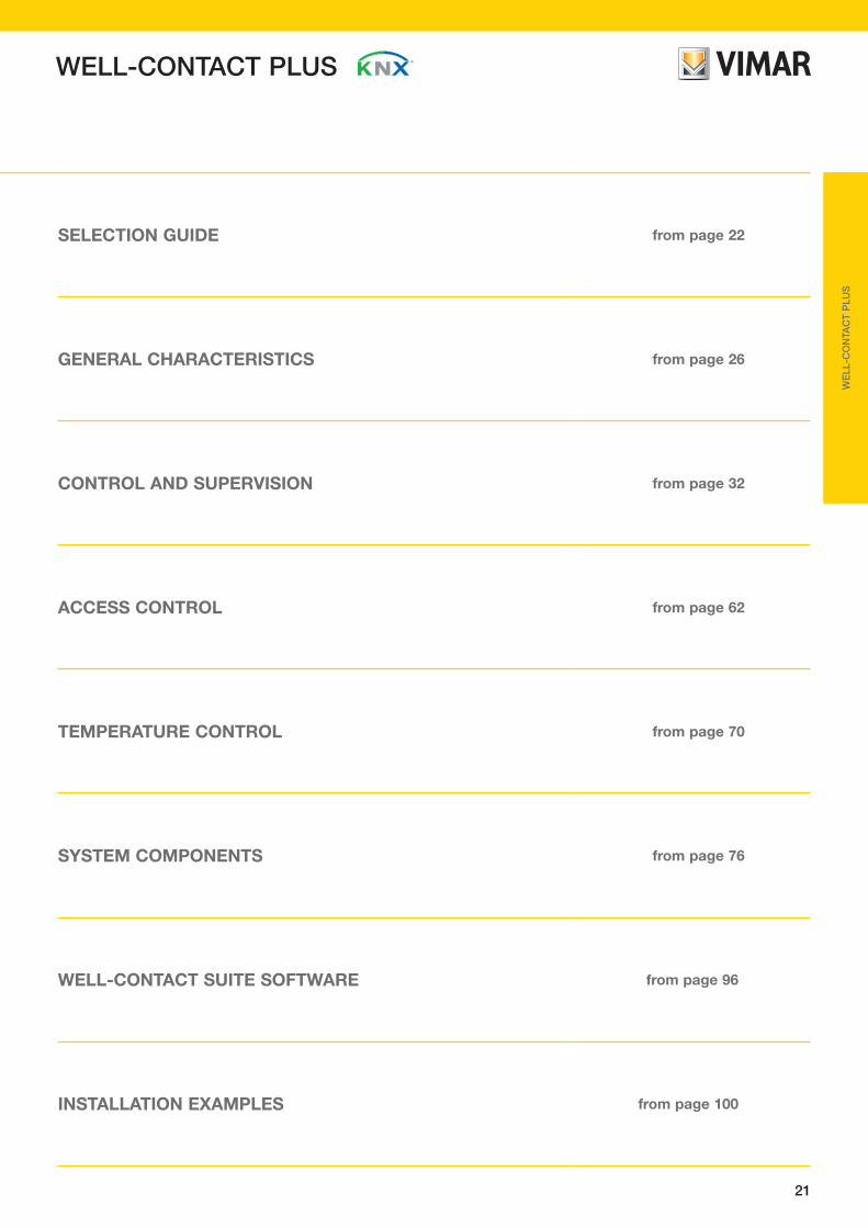
SELECTION GUIDE from page 22
GENERAL CHARACTERISTICS from page 26
CONTROL AND SUPERVISION from page 32
ACCESS CONTROL from page 62
TEMPERATURE CONTROL from page 70
SYSTEM COMPONENTS from page 76
WELL-CONTACT SUITE SOFTWARE from page 96
INSTALLATION EXAMPLES from page 100

22
Selection guideControl and supervision
Description CodeEikon
10” multimedia IP video touch screen, Due Fili Plus video door entry indoor station and web-server based home automation system supervisor, complete with mounting frame for installation on box V71318
Eikon Arké Plana
4,3” Full Flat colour touch screenfor control, Well-contact Plus, 1 input for temperature sensor, complete with support for installation in 8-module box
Full Flat colour touch screen for control, Well-contact Plus, 1 input for temperature sensor, 3 modules
Eikon Arké Idea Plana
4,3” colour touch screenfor control, Well-contact Plus, 1 input for temperature sensor, complete with support for installation in 8-module box
Full Flat colour touch screen for control and command, Well-contact Plus, 1 input for temperature sensor 3 modules
Monochrome touch screenfor local control, Well-contact Plus - 3 modules
Eikon Tactil
Control with 4 independent buttons for managing single loads or scenarios, KNX standard, to be completed with a label and Eikon Tactil cover plate - 2 modules
Control with 6 independent buttons for managing single loads or scenarios, KNX standard, to be completed with a label and Eikon Tactil cover plate - 3 modules
Eikon Arké Idea Plana
Control with 4 independent buttons KNX standard, visible in darkness, to be completed with button - 2 modules
Passive infrared presence detector, KNX standard - 2 modules
Eikon Arké Idea Plana
Web serverfor local and remote supervision of the KNX system, installation on DIN rails (60715 TH35), occupies 8 modules size 17.5 mm
∆ 19848.1grey
∆ 19848.1.Bwhite
∆ 14848.1white
∆ 14848.1.SLSilver
∆ 20848.1grey
∆ 20848.1.Bwhite
∆ 20848.1.NNext
21848grey
21848.Bwhite
21848.BNneutral
∆ 14849white
∆ 14849.SLSilver
14850white
14850.SLSilver
14840white
∆ 19849grey
∆ 19849.Bwhite
19850grey
19850.Bwhite
19840grey
16849grey
16849.Bwhite
16850grey
16850.Bwhite
∆ 20849grey
∆ 20849.Bwhite
∆ 20849.NNext
20850grey
20850.Bwhite
20850.NNext
20840grey
01545
21840
21860
∆ 21849grey
∆ 21849.BNneutral
21849.1grey
21849.1.Bwhite
21849.1.BNneutral
16840grey
16840.Bwhite
21553.1
WELL-CONTACT PLUS

23
WE
LL-C
ON
TAC
T P
LUS
Selection guide
Description CodeEikon Tactil
Transponder card readerfor installation outside the room, KNX standard, 2 relay outputs NO 4 A 24 V~, 2 inputs, power supply 12-24 V~ 50/60 Hz and 12-24 Vdc (SELV), to be completed with Eikon Tactil transponder cover plate - 3 modules.Supplied without transponder card
Eikon Arké Idea Plana
Transponder card readerfor installation outside the room, KNX standard, 2 relay outputs NO 4 A 24 V~ 2 inputs, power supply 12-24 V~50/60 Hz and 12-24 Vdc (SELV) - 3 modules.Supplied without transponder card
Transponder card reader with vertical pocket for installation inside the room, KNX standard, 2 relay outputs NO 4 A 24 V~, 2 inputs, additional power supply 12-24 V~ 50/60 Hz and 12-24 Vdc (SELV) - 3 modules
Transponder card reader/programmer with vertical pocket, with build-in table mounting box - 4 modules
Transponder cardfor programmable readers, customizable back
Access control
14457white
14457.SLSilver
14450white
14450.SLSilver
14453white
14453.SLSilver
19457grey
19457.Bwhite
19450grey
19450.Bwhite
19453grey
19453.Bwhite
16927grey
16927.Bwhite
16920grey
16920.Bwhite
16923grey
16923.Bwhite
20457grey
20457.Bwhite
20457.NNext
20450grey
20450.Bwhite
20450.NNext
20453grey
20453.Bwhite
20453.NNext
21457
01598
Description CodeEikon Arké Plana
Touch electronic thermostatfor ambient temperature control of 2 independent zones (heating and air-conditioning), KNX standard home automation, RGB LED backlighting - 2 modules
Eikon Arké Idea Plana
Electronic thermostatfor ambient air temperature control (heating/air-conditioning) of 2 independent zones, KNX standard, 1 NO relay output 4 A 24 V~, 1 input for temperature sensor, 1 programmable digital input - 2 modules
Electronic temperature sensor 1 output
Wired temperature sensor, cable length 4 m
Weather station, KNX standard, power supply 12-32 Vdc or 12-24 Vac
Temperature control
∆ 14430white
∆ 14430.SLSilver
14432white
14432.SLSilver
∆ 19430grey
∆ 19430.Bwhite
19432grey
19432.Bwhite
16915grey
16915.Bwhite
∆ 20430grey
∆ 20430.Bwhite
∆ 20430.NNext
20432grey
20432.Bwhite
20432.NNext
029522 modules
02952.B2 modules
02965
01546
∆ Available until stocks last
WELL-CONTACT PLUS

24
Description CodeDIN rail appliances (60715 TH35)
Line couplerKNX standard, it occupies 2 modules size 17,5 mm
B-type USB interfaceKNX standard, occupies 2 modules size 17,5 mm
Safety transformer230 V~, 12-24 V~ (SELV) 24 VA, for continuous service, occupies 3 modules size 17,5 mm
∆ 01504
01540
16887
Selection guide
System componentsDescription CodeDIN rail appliances (60715 TH35)
Power supply unit with Bus output of 30 Vdc320 mA, power supply 120-230 V~ 50/60 Hz, with decoupling coil, KNX standard, occupies 4 modules size 17,5 mm
Power supply unit with Bus auxiliary output of 30 Vdc640 mA, auxiliary output 30 Vdc, power supply 85-265 V~ 50/60 Hz, with decoupling coil, KNX standard, occupies 4 modules size 17,5 mm
Line couplerKNX standard, occupies 2 modules size 17,5 mm
01500
01504.1
01501.1
Components for the automation
01524
01522
Description CodeDIN rail appliances (60715 TH35)
Input/output device4 relay outputs NO 16 A 250 V~, 4 inputs for NO contacts, KNX standard, occupies 4 modules size 17,5 mm
Actuator for two roll-up blindswith relay outputs 16 A 250 V~, KNX standard, occupies 4 modules size 17,5 mm
Dimmer2 inputs for 01530, 2 relay outputs NO 16 A 250 V~, 2 outputs 1-10 V, KNX standard, occupies 4 modules size 17,5 mm
Interface with 4 programmable channelsas inputs or outputs for LEDs, KNX standard
Dimmer 230 V~ 50/60 Hzfor 2x300 W incandescent lamps, 2x300 VA ferromagnetic transformers, 2x300 VA electronic transformers, KNX standard, occupies 4 modules size 17,5 mm
01526
01528
01515
WELL-CONTACT PLUS
Description CodeDIN rail appliances (60715 TH35)
Actuator for fluorescent lampswith 12 relay outputs 10 A 250 V~ 50/60 Hz for fluorescent lamps, KNX standard, occupies 12 modules size 17,5 mm
Actuator for 8 roller shutters6 A 230 V~ 50/60 Hz relay outputs, KNX standard, occupies 8 modules size 17,5 mm
KNX DALI gateway8-channel for 16 lamps per channel, occupies 4 modules size 17,5 mm
KNX IP interfaceoccupies 4 modules size 17,5 mm
Device with 4 programmable digital inputsfor NO, NC contacts, 120-230 V~, KNX standard, occupies 2 modules size 17,5 mm
Actuator with 4 relay outputs NO 16 A 250 V~KNX standard, occupies 4 modules size 17,5 mm
01523
01510
01521
01525
01544
01547

25
WE
LL-C
ON
TAC
T P
LUS
Selection guide
Software and interfaceDescription Code
Well-contact Suite Software for managing and controlling devices in the Well-contact Plus system, complete with CD and hardware key
Hardware interfacefor programming By-me serial devices and configuring systems Well-contact Plus touch screens
Software suitewith EasyTool Professional LT, touch screen programming for the Well-contact Plus system complete with USB interface, EasyDraw and EasyCap software for designing and quoting electrical systems
∆ 01991
01993
01595WCS Management
WCS Gestionali WCS Office Client WCS Office WCS Client WCS Top WCS Basic
01592WCS Client
WCS Gestionali WCS Office Client WCS Office WCS Client WCS Top WCS Basic01590WCS Basic
WCS Gestionali WCS Office Client WCS Office WCS Client WCS Top WCS Basic 01591WCS Top
WCS Gestionali WCS Office Client WCS Office WCS Client WCS Top WCS Basic
01593WCS Office
WCS Gestionali WCS Office Client WCS Office WCS Client WCS Top WCS Basic01594WCS Office Client
WCS Gestionali WCS Office Client WCS Office WCS Client WCS Top WCS Basic
01589WCS Light
WELL-CONTACT PLUS
∆ Available until stocks last
Description Code
IR presence detector360° motion range, for lightings depending on the brightness, 0-100 Lux adjustable brightness range, KNX standard, for ceiling installation
Adapter for IR presence detectorfor 01529 with brightness sensor, ceiling installation
01529
01529.S
System components
01530
Description Code
Brightness sensorfor dimmer 01528, for ceiling installation
Cable2x2x0.8 mm, free of LSZH halogens, KNX standard, green - 100 m
01890

26
WELL-CONTACT PLUSGeneral characteristics
The range of products is completed by a DIN rail input/output device able to manage 4 inputs and 4 outputs, all freely programmable, that can be associated with additional services such as, for example, controlled sockets, room indicators, alarms and scenarios that enable the various users depending on who enters the room (guest, service personnel, maintenance engineer, etc.); everything will obviously always be supervised by reception that, thanks to the Well-contact Suite software, entirely developed by Vimar, will have control over all the events linked to the guest’s “history” for the entire duration of her stay.
The functions that each device must perform are programmed with the ETS software; in other words, a project is created in which each room is composed of a certain number of components, each of which is assigned operational parameters.
It will therefore be possible to choose, for instance, whether a relay must work in one-position stable, two-position stable, N/C or N/O mode or the type of thermostat temperature control (proportional integral, ON/OFF, etc.) or set up an input to recognize signal fronts, cyclical repetitions, etc..
ETS also enables Well-contact Plus devices to interact with other KNX appliances not supplied by Vimar, not only to make the system suitable for the widest range of applications, but also to be able to supplement it with existing devices (renovations).
The main competitive characteristics of the Well-contact Plus system can be summarized as follows:• no centralized intelligent room module is necessary;• all the functions and “intelligence” of the system are distributed
over the various appliances;• the recess-mounting devices that must be installed in the
room are equipped with free inputs and relay outputs that reduce the need for additional terminals;
• the system is extremely flexible thanks to the modularity of the range and its potential for easy, low-cost expansion to meet future needs;
• extremely simple, flexible system management software that also allows interfacing with the most widely used administrative software.
Field of applicationThe Well-contact Plus system, in the hotel and tertiary sector, enables making centralized management systems that allow integrating and supervising many functions and services efficiently guaranteeing simplicity of use by the personnel in charge.
More and more often, in fact, hotels and more in general hospitality facilities require systems for optimized and effective management of their services that simplify daily operation and, as far as possible, reduce running costs, optimizing energy savings and guaranteeing a high level of comfort for their guests.
The devices of the Well-contact Plus system, developed to KNX standard technology and aesthetically coordinated with the residential series of Eikon, Idea and Plana, offer technical solutions featuring outstanding efficiency, perfectly meeting all the most varied installation requirements and the constraints imposed by the different structures such as hotels, offices, shopping malls and the advanced tertiary sector in general.
Main characteristicsBased entirely on KNX technology, each device is able to perform the required functions directly; each component has resident intelligence that allows direct dialogue with all the devices in the network.The KNX standard was developed to create decentralized systems where the interchange of signals and commands takes place exclusively at the operational device level: that is, each component is able to process data independently and transmit and/or detect signals directly on the system's Bus. In short, therefore, each structure and each application can assign the priorities that it deems necessary without having to accept “take it or leave it” solutions and in any case without jeopardizing the possibility of a future implementation to extend the system’s functions.
Thanks to Well-contact Plus, each hospitality facility can select the most suitable solution, “customizing” it and ensuring the flexibility that only the common European protocol (KNX) can provide in terms of interoperability of devices and secure installation.
The single devices such as the external transponder reader, the reader with a pocket and the thermostat, besides the typical functions of card recognition and electrical lock opening, service activation and temperature control respectively, have freely programmable inputs and outputs that make the system really flexible.These inputs/outputs can be used to control sockets (courtesy lights, etc.), room service calls, alarms (ceiling pull, etc.) and energy savings (turning off the heating/air-conditioning after detecting an open window, etc.).

27
WELL-CONTACT PLUS
WE
LL-C
ON
TAC
T P
LUS
General characteristics
644
32
1
Bbc
LC
644
32
1 LC64
43
21 LC
644
32
1 LC64
43
21 LC
644
32
1 LC
...128
LC
644
32
1
Bbc
LC
644
32
1 LC64
43
21 LC
644
32
1 LC64
43
21 LC
644
32
1
...128
LC
644
32
1
Bbc
LC
644
32
1 LC64
43
21 LC
644
32
1 LC64
43
21 LC
644
32
1 LC
...128
LC
644
32
1
Bbc
LC
644
32
1 LC64
43
21 LC
644
32
1 LC64
43
21 LC
644
32
1
...128
LC
644
32
1
Bbc
LC
644
32
1 LC64
43
21 LC
644
32
1 LC64
43
21 LC
644
32
1 LC
...128
LC
644
32
1
Bbc
LC
644
32
1 LC64
43
21 LC
644
32
1 LC64
43
21 LC
644
32
1
...128
LC
644
32
1
Bbc
LC
644
32
1 LC64
43
21 LC
644
32
1 LC64
43
21 LC
644
32
1 LC
...128
LC
644
32
1
Bbc
LC
644
32
1 LC64
43
21 LC
644
32
1 LC64
43
21 LC
644
32
1
...128
LC
644
32
1
Bbc
LC
644
32
1 LC64
43
21 LC
644
32
1 LC64
43
21 LC
644
32
1 LC
...128
LC
644
32
1
Bbc
LC
644
32
1 LC64
43
21 LC
644
32
1 LC64
43
21 LC
644
32
1
...128
LC
644
32
1
Bbc
LC
644
32
1 LC64
43
21 LC
644
32
1 LC64
43
21 LC
644
32
1 LC
...128
LC
644
32
1
Bbc
LC
644
32
1 LC64
43
21 LC
644
32
1 LC64
43
21 LC
644
32
1
...128
LC
644
32
1
Bbc
LC
644
32
1 LC64
43
21 LC
644
32
1 LC64
43
21 LC
644
32
1 LC
...128
LC
644
32
1
Bbc
LC
644
32
1 LC64
43
21 LC
644
32
1 LC64
43
21 LC
644
32
1
...128
LC
644
32
1
Bbc
LC
644
32
1 LC64
43
21 LC
644
32
1 LC64
43
21 LC
644
32
1 LC
...128
LC
644
32
1
Bbc
LC
644
32
1 LC64
43
21 LC
644
32
1 LC64
43
21 LC
644
32
1
...255
LC
0
1
2
3
4
15
0
1
2
33
4
15
0
1
2
3
4
15
0
1
2
3
4
15
0
1
2
3
4
15
0
1
2
3
4
15
0
1
2
3
4
15
0
1
2
3
4
15
12 3
4 5 6 7
15
· up to 64 KNX devices that rising to 255
with additional line couplers
· max distance between two devices in the
same line: 700 m
· max distance between power supply
and device: 350 m Bd backbone line
LC
Bbc
1 64
Field coupler (15 max)
Line coupler (15 max)
KNX devices (64 max)
· up to 15 field couplers defining 15 fie
lds.
· max backbone lin
e length: 1000 m
To other systems
Mai
n l
ine
· up to 15 field coupler defining 15 fields.· max main line length: 1000 m
644
32
1
Bbc
LC
644
32
1 LC64
43
21 LC
644
32
1 LC64
43
21 LC
644
32
1 LC
...128
LC
644
32
1
Bbc
LC
644
32
1 LC64
43
21 LC
644
32
1 LC64
43
21 LC
644
32
1
...255
LC
...128
LC...
255LC
...128
LC...
255LC
...128
LC...
255LC
1
Well-contact Plus system general diagram
Up to three couplers can be connected to each line as repeaters, each one of which manages a segment of up to 64 devices with their power supplies for a maximum of 255 devices. The Bus line can be connected in different configurations (star, tree, etc.); the maximum length in any case must not exceed 1000 m.
Lines can be connected together with the 01504 couplers; it is possible to connect up to 15 lines on a single backbone, which is itself simply a line formed by all the couplers and the devices. This new element is called a field or area; the system can handle up to a maximum of 15 fields and this represents the maximum expansion of the system.
System architectureThe Well-contact Plus system uses a twisted pair cable as the means of transmission; using the Bus line not only simplifies installation/maintenance, but also ensures a high level of immunity from interference. Information is exchanged between the devices in “telegrams” composed of a set of bits whose combinations encode the transmitted information.
For the purposes of the application functions, the most important information transmitted by each device is the following:• the recipient address field indicating the devices to receive the
message;• the field containing the information related to the actual
function that the device must perform;• the sender’s address indicating the device that has sent the
message.
Each device has a specific “physical” address that identifies it uniquely in the system and therefore there can be no identical physical addresses.As regards the recipient address, under normal operational conditions, this is always a group address; the group addresses make “logical wiring” among different components and it is therefore possible to establish functional correlations (even very complex ones) among the various devices.
Modifying the group addresses with the special ETS configuration software changes the functions of the devices (for instance associations between inputs and outputs) without making any changes to the system wiring. The basic component of the system is the line segment; this is also the starting point for expanding the system up to the maximum possible configuration in terms of devices and shared functions. Each line segment can be composed of up to 64 devices (readers, thermostats, I/O devices, etc.) and needs one or two power supplies depending on the number of components. If two power supplies are used, they must be set apart at a distance of no less than 200 m.The maximum distance between a device and the power unit on the same line must not exceed 350 m.The maximum distance between two devices on the same line must not exceed 700 m.
ALIMENTATORE
ALIMENTATORE
ALIMENTATORE
Installation topologies of a line
LINEAR MIXED
STAR
POWER SUPPLY
POWER SUPPLY
POWER SUPPLY

28
WELL-CONTACT PLUS
NotesIn the diagram only some of the inputs and outputs equipping the devices are used.
To avoid electrical interference in the power supply circuit caused by the electric locks, it is advisable to power them with a dedicated transformer.
IMPORTANT:The transponder readers and the vertical pocket ones should be powered separately from all other loads (electric locks, lamps, con-tactors, etc.) using a transformer dedicated to them art. 16887 whose outputs should be used solely for these two devices.
*
General characteristicsExample of a hospitality facility: wiring diagram
FLOOR 1
12-24 V~
12-24 V~
230 V~
230 V~
Room 11
GROUND FLOOR Common areas
Reception
01504.1 01500
01500 01540
Courtesy light(230 V~)
Electric lock
20453
SV
12-24 V~
12-24 V~
Courtesy light(230 V~)(230 V~)
Contactwindow
01820
01504.1 01501.1
02952
21848 + 20788
Reception room light
BALLAST
0-10 V LN
V+
V+
V-
V-
L2
L1
L3
N
230 V~
01526 01528
Conference room light
01530
SV
Contactwindow
01820
02952
(230 V~)
21849 20840+ (2) 20841.0+ (2) 20841.2
Bath-room ceiling pull-cord Lamp 1
(230 V~)
Lamp 2 (230 V~)
20457
Fridge-minibarDoor open indicator
Room ser-vice call button
M
Fan coil
230 V~
01522
KNX Bus
KN
X B
us
KNX Bus
LN
* *
*
Electric lock
20457

29
WELL-CONTACT PLUS
WE
LL-C
ON
TAC
T P
LUS
equipped with an additional supplementary power supply with respect to the connection on the KNX Bus 12-24 V.
• evaluate accurately, according to the size of the property, whether a line can be considered as a floor or whether a line can cover a number of floors or, vice versa, whether the property is so large that covering a floor requires a number of lines (therefore, at the design stage, take account of the characteristics of a line in terms of number of devices and distances);
• the number of lines forming the system will determine the number of couplers that must be installed (the lines are con-nected together by line couplers that allow communication between devices belonging to different lines);
• at the design stage, always try and bring each type of system into line with the diagram in the figure on page 15; this is to determine the correct position of the various devices within the system.
The installation examples give the layouts illustrating part of a typical hotel system; all the devices given in the examples are summarised in the general structure of the Well-contact Plus system (see the above table). The ground floor is composed of: reception, dining hall, administrative office, conference hall, technical room and store, while on the other floors there are the guest rooms. In each room on the first floor, the following items are installed:• an external transponder reader to access the room and
display the messages via the 4 front LEDs;• a reader with a pocket to activate the associated loads
(services); • a thermostat to control the temperature set-point;• a control with four independent push buttons for “do not
disturb”, “room service call” and “lights control” functions;In the suites, in place of the control with four independent push buttons, two 3-module touch screens are installed to govern lights, climate and any scenarios.
The transponder readers are additionally used to distinguish between accesses to the offices and to the other places (store, technical room, etc.) located on the ground floor; this highlights how the Well-contact Plus system can easily be used in both hotels and the tertiary sector.
Example of system compositionWhen creating an installation with the Well-contact Plus system the following components are used: • Power supplies• Line coupler• Transponder card reader• Transponder card reader with pocket• Thermostat• 4,3” colour touch screen• 3-module monochrome touch screen• Control with 4 independent push buttons• Transponder card reader/programmer• Input/output device• USB interface
Preparing the systemIt is important, in the phase of preparing the system, to have a clear idea of which functions and applications are to be created and obviously this will depend on the type and complexity of the property where the installation is to be made. The system is composed of a range of 8 types of devices; it will be in the configuration phase with ETS where you assign the “task” that each of these devices must perform, which will be the input/output associations and the services to control.
IMPORTANT: The transponder readers and the vertical pocket ones should be powered separately from all other loads (electric locks, lamps, contactors, etc.) using a trans-former dedicated to them art. 16887 whose outputs should be used solely for these two devices.
As regards the actual preparation of the system and therefore laying out the cables and positioning the devices, it will be enough to take into account the characteristics given in the above table, observing the following precautions:• add up the power inputs of the single devices (that must be
no more than 64 for each line segment) so as to determine the number of power supplies to install; if the current draw of the devices in a line is greater than the current delivered by the power supply (for instance 320 mA) it is necessary to connect an additional power supply or use a power supply able to deliver a greater current (for instance 640 mA);
• the transponder readers and the ones with a pocket are
Well-contact Plus system Characteristics
Bus devices Number of Bus devices for each single line segment max 64 (with power supply 640 mA)
Number of lines max 16 per field (total 241 lines)
Number of fields max 15
Maximum distance between two devices 700 m
Power supply Minimum working voltage 21 Vdc
Number of power supplies for line segments max 2
Max current per line 640 mA
Minimum distance between the two power supplies 200 m
Topology Permitted connections linear, tree, star and mixed
Transmission Transmission technology decentralized, by event, serial, symmetrical
Transmission speed 9600 baud
Cable Bus cable section 2 x 2 x 0.8 mm2
Max length per line 1000 m
General characteristics

30
WELL-CONTACT PLUS
ETS SoftwareFor the design, configuration of the various appliances and the commissioning of the system, installers have the ETS software (Engineering Tools Software), marketed by KNX Association.Using a PC and the ETS software, you address the different devices operating in the system and establish the related functional correlations (or group addresses).Establishing the functional correlations means using software to define how each device must intervene following the events occurring in the system, for instance which lamp or group of loads must switch on when a card is inserted in the reader with a pocket or a particular switch is pressed.The operating mode of KNX appliances is also determined by the application program selected from among the available ones for that device and by the appropriate configuration of the related operating parameters.
The application programs of Vimar KNX devices are freely available on the company’s website www.vimar.com.The addresses and operating parameters are transferred to the various devices by connecting the PC to the KNX Bus via the KNX USB interface 01540.The ETS software utilizes simple graphical user interfaces that facilitate device configuration also in relation to the building’s layout.
To purchase the ETS software, obtain a free “demo” version or receive more technical and commercial information we suggest you contact the KNX Association.
Supervision and control at a higher levelAs already mentioned the KNX distributed intelligence systems also enable supervision and control at a higher level (centralized).Use of PCs and special software enables centralizing the system’s functions, but in no way does it jeopardize their operation if the PC is switched off or malfunctions.
Note.In a Well-contact Suite system, when using the ETS project, there must be no groups with the same name: for example it will be necessary to distinguish between “power room 101” and “power room 102.” ETS project creation respecting this clause will enable the Well-contact Suite software to distinguish
automatically between the group addresses it must display and the ones it must mask for each room, considerably facilitating the task of room creation with Well-contact Suite.
General characteristics
230 V ~
Lettore a transponderInterfaccia USB
01540204571692714457
+ ETS+ Software applicativi
i - BUS KNX
Dispositivo di ingresso/uscita0152202952
16921
Termostato
1. Definition of physical addresses, functional cor-relations and operational parameters for the various system devices.
2. Transfer of addresses and parameters to the appliances.
3. At the end of the operations the PC can be removed, to be, if necessary, reconnected only for functions of diagnostics, changes to the parameters, addresses and functional or expansional correlations of the system.
Configuration phases
+ ETS+ applications software
Transponder reader
Thermostat Input/output device
USB interface
ETS software window
Group addresses
Building topology
Buildings

31
WELL-CONTACT PLUS
WE
LL-C
ON
TAC
T P
LUS
Depending on the functions to be implemented, therefore, the most appropriate choices can be made to optimize the costs that the client will have to sustain.
Solutions for the Tertiary SectorThe versatility of these components and the Vimar WCS Office and WCS Office Client software enables flexible management of tertiary sector applications and particularly productions within the framework of office buildings; similar in use, the requirements in office buildings/blocks adhere perfectly to the functions performed by the Vimar components with the KNX standard.Thanks to the peculiarities of the KNX standard it is possible to expand the system at any time with devices already present on the market able to satisfy even the most sophisticated and specific applications, such as for instance controlling the opening of a passage, complete management of lights and temperature, programmable also by floor, side of exposure or single office. The system applications can therefore be the most varied; from access diversification to customizing each single office with the generation of cards that also allows access to common rooms such as, for instance, general entrances, canteens/restaurants, reserved lounges, conference rooms, etc., all using the transponder reader. With the aid of the pocket reader it will then also be possible, in all those rooms not normally controlled by time programs or motion detectors, to manage the lighting or temperature (energy savings).
The topic of lighting in offices is by now the subject of specific design studies; switching on lamps not only with a manual control but also with programs linked to time or to the side of exposure to sunlight enables significant energy savings; with the input/output devices it is possible, for instance, to connect light sensors capable of detecting the degree of brightness and switch lights on and off in a differentiated manner according to the set threshold value. With these same devices it is also possible to transmit status or alarm signals from auxiliary contacts or remote sensors that can be displayed both on the readers and on the monitoring PC (if applicable). Lastly, as regards temperature control, in modern office buildings the possibility of switching on the heating or air-conditioning in a differentiated manner has become an increasingly requested comfort requirement especially for the savings provided in terms of energy optimization; all of this can be performed by suitably programming the thermostats of the Well-contact Plus system.
Well-contact Suite SoftwareWell-contact Suite (WCS) is a family of software products (WCS Light, WCS Basic, WCS Top, WCS Client, WCS Office, WCS Client Office and WCS Management) that enables managing/supervising the entire system with operations of check-in, room status, events memory, alarm control, temperature control, guest file, etc. The following chart gives the functions of the Suite.
Controllable functionsCard identification
Guest Room Check-in\Check-out
Management of Services and Privileges (creation of cards with services enabling)
Access log and display
Stopping access to single rooms
Room booking
Displaying room reserved, booked, occupied, identification of guest in room
Displaying length of stay, day of departure
Checking PW of personnel with hourly and area limitation
Diversification of users (guests, service personnel, etc.)
Displaying different types of alarms and changing the warning status
Protection with unique Hardware Key for guest
Searching and exporting entry report
Checking and managing transit through common areas
Advanced search functions (by text categories)
Displaying service requests
Managing the records of the hotel’s staff and guests
Guest book with any saved parameters
Supervision (temperatures, I/O, alarms, security, lights)
Guest management with Client-Server Logic on local area network or remotely via web
Levels of protection (password) for differentiated access
Seven levels of access “privileges” to be associated with the software users
Possibility of managing scenarios and commands of virtual devices
Room supervision screen Customer card screen
General characteristics

32
WELL-CONTACT PLUSSupervision10" IP Multimedia video touch screenThe multimedia video touch screen is a Due Fili Plus indoor video door entry unit that integrates with all the other devices in the video door entry system (entrance panels, call buttons, power supplies, etc.) and allows you to manage video door entry functions such as viewing and voice communication with the caller, electric lock opening, switching on stair lighting and other auxiliary functions, intercom calls, baby watching, man-aging analogue cameras connected to the IP or Elvox Due Fili Plus system, ringtone customization, missed call management and the video door entry phone answering service. Besides the function of a video door entry unit, if the system includes the web server (01545), the device enables monitoring and controlling all the devices in the Well-contact Plus system. In addition, if the network to which it is connected is enabled for web browsing, the device also features some pre-installed applications that allow you to take advantage of services such as weather forecasts, news, RSS feed reader, and a web radio controller. Other off-line applications are instead always active, providing additional functionality (video and photo viewing, MP3 player, calendar with reminders, graphic, text or audible notes).
Technical specifications• 10” horizontal touch screen• SDHC port for saving voicemail and multimedia files• Reset button • Installation, with mounting frame provided, on 8-module flush
mounting box V71318. Important: The flush mounting box must always be installed in a vertical position
Video door entry function• View call from external station;• Communication with external station or call button;• Open electrical lock;• Switch on stair lights or other auxiliary function;• Make or receive intercom calls with other video touch
screens, video door entry systems and hands-free entry phones;
• Audio monitoring; • View images received from multiple video cameras for room
monitoring, baby watching, etc.;• web server answering service for remote access
Automation functions• automation functions (automation functions require the web
server KNX 01545 to be installed)• ON/OFF command and light dimming• Roller shutter and blind control• HVAC control• Scenario activation• Analogue camera viewing over Due Fili Plus Bus• IP camera viewing via LAN connection• viewing cameras connected to DVR and controlling them via
APP
ConfigurationIf you are using the device as a video door entry unit, configu-ration is done directly on the screen using the wizard with a simple graphical interface. Whereas, if you want to configure the device as a Well-contact Plus system supervisor combined with the web server KNX 01545, you need to use the ETS software and set the corresponding communication objects. After con-necting the multimedia video touch screen to the web server via the Ethernet port, you can supervise the entire home automa-tion system by accessing the database on the web server.
Conformity to StandardsLV Directive, EMC DirectiveStandards EN 60950-1, EN 61000-6-1, EN 61000-6-3
21553.1 - Connections
290
217,
5Video door entry terminals
Power: 230 V
Power: 12 VAudio signal terminalsRJ45 socket
Technical datapower supply 12 Vdc, 230 Vaccurrent draw at 12 Vdc 600 mAcurrent draw at 230 Vac 150 mAaudio/video module current draw 120 mAoperating temperature from - 5 °C to + 40 °C (indoor use)
Inputspower supply 12 Vdc + -Power: 230 V N Lconnection with web server 01945 RJ45Bus digital line (Due Fili Plus) 1, 2 (input/output)supplementary power supply (+28 Vdc, 24 Vac) E+supplementary power supply (GND, 24 Vac) E-N/O landing push button (bell function) FPground reference for N/O landing push button M
Outputsto distribute an audio signal separately from the main one
LINE OUT (Left and Right)
power supply for supplementary relay/ringtone +12control for supplementary relay/ringtone CH

33
WELL-CONTACT PLUS
The drawings of the side views give the overall dimensions and the flush depth in mm
WE
LL-C
ON
TAC
T P
LUS
Supervision10" IP Multimedia video touch screen10” multimedia IP video touch screen, Due Fili Plus video door entry indoor station and web-server based home automation system supervisor, complete with mounting frame for installation on box V71318. Cover plate not supplied.
21553.1
EIKON60,5
217,
5
Examples of multimedia video touch screenshots
Menu selection
Browsing the web page for the weather forecast
Video entry phone settingsIncoming video call:
Web “News” pageViewing rooms with cameras
Cover plates for 10” multimedia video touch screen
21665.11aluminium
21665.70diamond white
21665.76diamond black

34
WELL-CONTACT PLUSSupervision4.3” full flat colour touch screenThe device is used in the Well-contact Plus automation system to command lights, roller shutters, HVAC and scenarios. An external temperature sensor (20432, 19432, 14432) can be connected to the touch screen in order to monitor climate in the area in which the sensor is installed (maximum length of cable connecting sensor to devices: 60 m).The touch screen is configured via the KNX Touch Screen Configurer software (contained in art. 01991) connecting the USB interface to the special connector on the front of the device. The touch screen allows the supervision and control of all the devices in the automation system that have been configured. Technical specifications• display: 4.3” TFT• connect to the auxiliary output of the power supply 01501.1 • external temperature sensor (20432, 19432, 14432): maxi-
mum length of the cable connecting the sensor to the devic-es: 60 m. Use a twisted cable with a minimum cross-section of 0.5 mm2 (01840)
• possible functions:- ON/OFF switch (lights on/off)- roller shutters control- dimmer control (light dimming)
- scenario activation - HVAC control.• number of pages: up to 60 pages with 8 icons each (a dim-
mer / roller shutter and the HVAC occupy 2 icons)
ConfigurationThe touch screen is configured using the KNX Touch Screen Configurer and the programming interface 01991; the functions (groups, scenarios, etc.) to be commanded via the touch screen are selected from the database of the ETS project with which the system was configured.The KNX Touch Screen Configurer software can be down-loaded free of charge from the “Software di prodotto” (Product Software) section of the website www.vimar.com.All the updated ETS databases can be downloaded from the “Software di prodotto” (Product Software) section of the web-site www.vimar.com. Moreover, when configuring with EasyTool Pro LT, you can custom configure the colour aspect of the 4.3" touch screen by choosing between “black skin” and “white skin”, for a perfect total look of the entire system.
Technical datapower supply 12-29 Vdccurrent draw at 12 Vdc 120 mAcurrent draw at 29 Vdc 60 mAcurrent draw from the Bus 10 mA
operating temperature from - 5 °C to + 40 °C (indoor use)
Inputspower supply 12-29 Vdc V+ V-KNX TP Bus Bus + -
external temperature sensor (20432, 19432, 14432)
connection with interface 01991 PIN-STRIP connector
OperationTouching the icons on the main screen for the four main menus opens the subsequent screens that enable you to control and command the Well-contact Plus system using the icons displayed each time.
Conformity to StandardsEMC directiveStandard EN 50428, EN 50090-2-2
21848 - Front view and connections TP Busbar terminals power supply terminals 12 - 29Vdc
temperature sensor terminals
display
PIN-STRIP connector for connecting to interface 01991
“Black and white skin” screenshots

35
WELL-CONTACT PLUS
The drawings of the side views give the overall dimensions and the flush depth in mm
WE
LL-C
ON
TAC
T P
LUS
Supervision
EIKON ARKÉ and PLANA
4,3” Full Flat colour touch screen4,3” Full Flat colour touch screen for control, Well-contact Plus, 1 input for temperature sensor, complete with mounting frame for installation in 8-module box. To be completed with Eikon, Arké or Plana 8-module cover plates
21848.Bwhite
21848grey
21848.BN*neutral
140,1
144
50,4
39,910,5
119,
6
*Ideal for matching with the Next version of other devices.
V71318V71328 V71631
20788grey
14788white
14788.SLSilver
19788grey
19788.Bwhite
20788.Bwhite
20788.NNext
Accessories for 4.3” colour touch screen V71318 8-module flush mounting box (GW 650°C), for masonry walls, blueV71718 8-module flush mounting box (GW 850°C), for light walls, blueV71328 Anti-mortar protective cover for V71318 and V71718 boxes, yellowV71631 Cover for flush mounting boxes V71318 and V71718, to be fixed to the anti-mortar cover V71328 included, white
20788 .B .N Table mounting box 8 modules (4+4). Equipped with frame for Eikon Classic or Round 8-module cover plate. To be completed with Eikon Classic or Round cover plate
19788 .B As above, for Arké14788 .SL As above, for Plana21668... Eikon Evo: 8-module cover plate (4+4): Premium (anodized aluminium), Exclusive (faced aluminium), Sculpted (carved stone), Natural
(solid wood), Luminous (crystal), Refined (natural leather), Special (Corian®) and Essential (total aluminium and glass)
20668... Eikon: Classic 8-module cover plate (4+4): Bright (painted metal), Galvanic (galvanic metal), Stainless steel, Stone, Wood (solid wood), Glass (crystal) and Reflex (technopolymer)
20698... Eikon: Round 8-module cover plate (4+4): Bright (painted metal), Galvanic (galvanic metal), Stainless steel, Wood (solid wood) and Glass (crystal)
19668... Arké: Classic 8-module cover plate (4+4): Metal-Color (painted metal) Metal-Elite (faced metal), Alu-Tech (aluminium), Wood (solid wood), Color-Tech (painted technopolymer) and Tecno-Basic (technopolymer)
19698... Arké: Round 8-module cover plate (4+4): Metal-Color (painted metal) Metal-Elite (faced metal), Wood (solid wood), Reflex Plus (reflex), Color-Tech (painted technopolymer) and Tecno-Basic (technopolymer)
14668... Plana: 8-module cover plate (4+4), available in these finishes and colours: technopolymer and Reflex
V71718
20698... 19698...21668... 20668... 19668... 14668...

36
WELL-CONTACT PLUSSupervision4.3” colour touch screen for monitoring and controlTouch screen device to be used in the automation system for controlling lights, roller shutters, air-conditioning and scenarios.An external temperature sensor (20432, 19432, 14432) can be connected to the touch screen in order to monitor climate in the area in which the sensor is installed (maximum length of cable connecting sensor to devices: 60 m). The device is configured with the KNX Touch Screen Configurer software connecting the interface 01991 to the special connector on the front of the device. The touch screen allows the supervision and control of all the devices in the automation system that have been con-figured.
Technical specifications• TFT 4.3” display• possible functions:
- ON/OFF switch (lights on/off)- roller shutter and blinds control- dimmer control (light dimming)- scenario activation- HVAC control- display of the main physical data (m/s, m/s2 A, V, °C, °F, °K,
Lux, etc.)• number of pages: up to 60 with 8 icons each (one dimmer/
roller shutters occupies 2 icons)
ConfigurationThe touch screen is configured using the KNX Touch Screen Configurer and the programming interface 01991; the func-tions (groups, scenarios, etc.) to be commanded via the touch screen are selected from the database of the ETS project with which the system was configured.The KNX Touch Screen Configurer software and the updated ETS databases can be downloaded free of charge from the “Software di prodotto” (Product Software) section of the web-site www.vimar.com.
Conformity to StandardsEMC directive, Standard EN 50428, EN 50090-2-2
OperationTouch the icons on the main screen for room control and the touch screen settings to access the following screens that
enable checking and controlling the system with the icons displayed.
20848.1 - Front view and connections
terminalsKNX TP Bus
power supply terminals 12 - 29 Vdc
display
PIN-STRIP connector for connecting to inter-face 01991
Main menu
Room Selection Settings
Example of “white skin” configuration of the touch screen
Room control Local temperature
Technical datapower supply 12-29 Vdccurrent draw at 12 Vdc 120 mAcurrent draw at 29 Vdc 60 mAcurrent draw from the Bus 10 mA
operating temperature from - 5 °C to + 45 °C (indoor use)
Inputspower supply 12-29 Vdc V+ V-KNX TP Bus Bus + -
external temperature sensor (20432, 19432, 14432)
connection with interface 01991 PIN-STRIP connector

37
WELL-CONTACT PLUS
The drawings of the side views give the overall dimensions and the flush depth in mm
WE
LL-C
ON
TAC
T P
LUS
Supervision
PLANA
ARKÉ
EIKON
∆ 20848.1grey
∆ 20848.1.NNext
∆ 14848.1.SLSilver
∆ 19848.1.Bwhite
11 39,9
144
140,1
136
119,
6
50,9
∆ 20848.1.Bwhite
∆ 14848.1white
∆ 19848.1grey
Colour touch screen 4,3”4,3” colour touch screen for control, Well-contact Plus, 1 input for temperature sensor, complete with mounting frame for installation in 8-module boxes
∆ Available until stocks last

38
WELL-CONTACT PLUSSupervision3-module Full Flat colour touch screen for room controlTouch screen device with colour display to be used in the Well-contact Plus automation system to control lights, roller shutters, HVAC and scenarios. The device allows you to con-nect an external temperature sensor (20432, 19432, 14432) to view climate in the area in which the sensor is installed (maximum length of cable connecting sensor to devices: 60 m). The device is configured with the KNX Touch Screen Configurer software connecting the interface 01998 to the special connector on the front of the device. The touch screen can be installed either horizontally or vertically. It is recom-mended to install the touch screen at a height of 150 cm from the floor level.
Technical specifications• possible functions:
- ON/OFF control (lights on/off);- roller shutters control;- dimmer control (light dimming);- scenario activation;- HVAC control;- 5 pages (screens) that can be configured to control a room.
ConfigurationThe Full Flat touch screen is configured using the KNX Touch Screen Configurer and the programming interface 01998; the functions (groups, scenarios, etc.) to be commanded via the touch screen are selected from the database of the ETS project with which the system was configured.The KNX Touch Screen Configurer software and the updated ETS databases can be downloaded free of charge from the “Software di prodotto” (Product Software) section of the web-site www.vimar.com.Moreover, when configuring, you can custom configure the colour aspect of the 3-module colour Full Flat touch screen by choosing between “black skin” and “white skin”, for a perfect total look of the entire system.
OperationTouch the icons on the main screen of the colour display to access other icons that enable controlling the associated Well-contact Plus devices and make the settings (date, time, etc.).
Conformity to StandardsEMC Directive, EN 50428 standard
Examples of screens
PIN-STRIP connector for connecting to interface 01991
TP Busbar terminalsexternal temperature sen-sor terminals
display
21849.1 - Front view and connections
HVAC control Room Management
Technical datapower supply via Bus 30 Vdc SELVcurrent draw from Bus 42 mAoperating temperature from - 5 °C to + 40 °C (indoor use)
InputsKNX TP Bus Bus + -
external temperature sensor (20432, 19432, 14432)
connection with interface 01991 PIN-STRIP connector

39
WELL-CONTACT PLUS
The drawings of the side views give the overall dimensions and the flush depth in mm
WE
LL-C
ON
TAC
T P
LUS
Supervision3-module Full Flat colour touch screen for room control Full Flat colour touch screen for room control, Well-contact Plus, 1 input for temperature sensor - 3 modules
21849.1.Bwhite
21849.1grey
∆ 21849grey
21849.1.BN*neutral
∆ 21849.BN*neutral
67,3
49
37
45,3
67,3
49
37
45,3
EIKON ARKÉ and PLANA
EIKON
*Suitable for matching with white and Next versions of other devices.
∆ Available until stocks last

40
WELL-CONTACT PLUSSupervision3-module monochrome touch screen for room controlDevice with a touch screen to be used in the automation system for controlling lights, roller shutters, air-conditioning and scenarios. The device is configured with the KNX Touch Screen Configurer software connecting the interface 01998 to the special connector on the back of the device. The touch screen can be installed either horizontally or vertically.
Technical specifications• possible functions:
- ON/OFF control (lights on/off)- roller shutters control- dimmer control (light dimming)- scenario activation- HVAC control- display of the main physical data (m/s, m/s2 A, V, °C, °F, °K,
Lux, etc.)- up to 3 screens that can be configured for controlling a
room• number of pages: 3 with up to 8 icons each (one dimmer/
roller shutters occupies 2 icons)
ConfigurationUsing the ETS project database with which the system was configured, select the functions (groups, scenarios, etc.) that you want to control via the touch screen The KNX Touch Screen Configurer software and the updated ETS databases can be downloaded free of charge from the “Software di prodotto” (Product Software) section of the website www.vimar.com.
OperationTouch the icons on the main screen to access other icons that enable controlling the associated devices and make the settings (date, time, etc.) on the touch screen.
Conformity to StandardsEMC directiveStandard EN 50428, EN 50090-2-2
Main menu
Display Setting menu Room Control menu Information menu
display
20849, 16849 and 14849 - Front view and connections of touch screen
PIN-STRIP connector for connecting to interface 01991
KNX TP Bus terminals
Technical datapower supply via Bus 30 Vdccurrent draw from Bus 10 mA
operating temperature from - 5 °C to + 45 °C (indoor use)
InputsKNX TP Bus Bus + -connection with interface 01991 PIN-STRIP connector
Tap
Press
Flick
Drag oriz
Drag vert
Tap
Press
Flick
Drag oriz
Drag vert
Tap
Press
Flick
Drag oriz
Drag vert

41
WELL-CONTACT PLUS
The drawings of the side views give the overall dimensions and the flush depth in mm
WE
LL-C
ON
TAC
T P
LUS
Supervision3-module monochrome touch screenMonochrome touch screen for room control, Well-contact Plus - 3 modules
37
46,5
67,3
49
36,8
47
74,8
50,2
36
46,5
67,3
49
EIKON
∆ 20849grey
∆ 20849.NNext
∆ 20849.Bwhite
∆ 19849grey
∆ 19849.Bwhite
ARKÉ 46,2
36,5 67,2
49
∆ 14849white
∆ 14849.SLSilver
16849grey
16849.Bwhite
IDEA
PLANA
∆ Available until stocks last
42
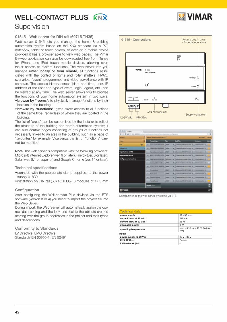
WELL-CONTACT PLUSSupervision01545 - Web server for DIN rail (60715 TH35)Web server 01545 lets you manage the home & building automation system based on the KNX standard via a PC, notebook, tablet or touch screen, or even on a mobile device provided it has a browser able to view web pages. The Vimar By-web application can also be downloaded free from iTunes for iPhone and iPod touch mobile devices, allowing even faster access to system functions. The web server lets you manage either locally or from remote, all functions asso-ciated with the control of lights and roller shutters, HVAC, scenarios, "event" programmes and video surveillance with IP cameras. The access history screen (date and time, user, IP address of the user and type of event, login, logout, etc.) can be viewed at any time. The web server allows you to browse the functions of your home automation system in two ways:• browse by “rooms”: to physically manage functions by their
location in the building;• browse by "functions": gives direct access to all functions
of the same type, regardless of where they are located in the building;
The list of "areas" can be customized by the installer to reflect the structure of the building and home automation system; it can also contain pages consisting of groups of functions not necessarily linked to an area in the building, such as a page of "favourites" for example. Vice versa, the list of "functions" can-not be modified.
Note. The web server is compatible with the following browsers: Microsoft Internet Explorer (ver. 9 or later), Firefox (ver. 6 or later), Safari (ver. 5.1 or superior) and Google Chrome (ver. 14 or later).
Technical specifications• connect, with the appropriate clamp supplied, to the power
supply 01830• installation on DIN rail (60715 TH35): 8 modules of 17.5 mm
ConfigurationAfter configuring the Well-contact Plus devices via the ETS software (version 3 or 4) you need to import the project file into the Web Sever.During import, the Web Server will automatically assign the cor-rect data coding and the look and feel to the objects created starting with the group addresses in the project and their types and descriptions.
Conformity to StandardsLV Directive, EMC DirectiveStandards EN 60950-1, EN 50491
01545 - Connections
01545WEB SERVER
FUNCTION
RESET
CARD
SD
POWER
12V-30V= BUS
Access only in case of special operations
Supply voltage onLAN network jack
KNX Bus12-30 Vdc
Configuration of the web server by setting via ETS
Technical datapower supply 12 - 30 Vdccurrent draw at 12 Vdc 210 mAcurrent draw at 30 Vdc 85 mAdissipated power 4 W
operating temperature from - 5 °C to + 45 °C (indoor use)
Inputspower supply 12-30 Vdc 12 V - 30 VKNX TP Bus Bus + -LAN network jack -

43
WELL-CONTACT PLUS
WE
LL-C
ON
TAC
T P
LUS
Supervision
01945
Examples of management from web server browser
Rooms page
Loads page
Lighting page
Consumption page
Web server for DIN rail (60715 TH35)01545 Web server for local and remote supervision of the KNX system, installation on DIN rails (60715 TH35), occupies 8 modules size 17.5 mm

44
WELL-CONTACT PLUSControl and supervisionControl with 4 programmable buttonsHome automation control device, 4 independently program-mable buttons for managing single loads or scenarios, to be completed with a label and Eikon Tactil cover plate.
The device consists of 4 independent touch buttons that, via the KNX Bus, enable controlling relay actuators, dimmer actua-tors and roller shutter actuators; they can also be used for call-ing up scenarios.The device is to be completed with the glass cover plate; the buttons however react to mechanical pressure even without fit-ting the cover plate so the configuration and the first operating test can be performed in this condition.
You can define the colour of each icon with respect to the RGB range. Once set via ETS, the colour will remain associated with that icon regardless of the type or state of the load it controls. Via ETS it is possible to choose whether, when at rest, the device will remain with the button icons totally off, or all backlit at 30% brightness.
Conformity to StandardsEMC directiveStandards EN 50428, EN 50491
Control with 6 programmable buttonsGlass touch control device, 6 independently programmable buttons for managing single loads or scenarios, KNX standard, to be completed with a label and Eikon Tactil cover plate.
The device consists of 6 independent touch buttons that, via the KNX bus, enable controlling relay actuators, dimmer actua-tors and roller shutter actuators; they can also be used for call-ing up scenarios.The device is to be completed with the glass cover plate; the buttons however react to mechanical pressure even without fit-ting the cover plate so the configuration and the first operating test can be performed in this condition.
You can define the colour of each icon with respect to the RGB range. Once set via ETS, the colour will remain associated with that icon regardless of the type or state of the load it controls. Via ETS it is possible to choose whether, when at rest, the device will remain with the button icons totally off, or all backlit at 30% brightness.
Conformity to StandardsEMC directiveStandards EN 50428, EN 50491
NOTE: On controls 21840 and 21860 you can affix the labels (21847) to determine the symbol that will be displayed by the client for that button.
21840 - Front view and connections
21860 - Front view and connections
KNX TP Bus terminals
KNX TP Bus terminals
Configu-ration button
A
B
LED for icons
LED for icons
LED for icons
LED for icons
Configu-ration LED
A: Configuration buttonB: Configuration LED
Technical datapower supply via Bus 30 Vdc SELVcurrent draw from Bus 35 mA
operating temperature from - 5 °C to + 45 °C (indoor use)
InputsKNX TP Bus Bus +, -
Technical datapower supply via Bus 30 Vdc SELVcurrent draw from Bus 35 mA
operating temperature from - 5 °C to + 45 °C (indoor use)
InputsKNX TP Bus Bus +, -

45
WELL-CONTACT PLUS
The drawings of the side views give the overall dimensions and the flush depth in mm
WE
LL-C
ON
TAC
T P
LUS
Control and supervision
EIKON TACTIL
EIKON TACTIL
EIKON TACTIL
21840
44,3
38 44,9
49
Control with 4 programmable buttonsAutomation control device, 4 independently programmable buttons for managing single loads or scenarios, KNX standard, to be completed with a label and Eikon Tactil cover plate - 2 modules
Control with 6 programmable buttonsAutomation control device, 6 independently programmable buttons for managing single loads or scenarios, KNX standard, to be completed with a label and Eikon Tactil cover plate - 3 modules
21860
44,3
38 67,4
49
Adhesive labels for customizing Eikon Tactil8 sheets of stickers with lightable symbols and lettering for standard functions for customizing Eikon Tactil controls
21847
Instructions for customisation• The controls must be customized by affixing
an adhesive label (21847) in the designated areas of the device (top and bottom);
• The symbol is backlit with RGB colours to be set during system programming.
Control customized by fixing labels
Label
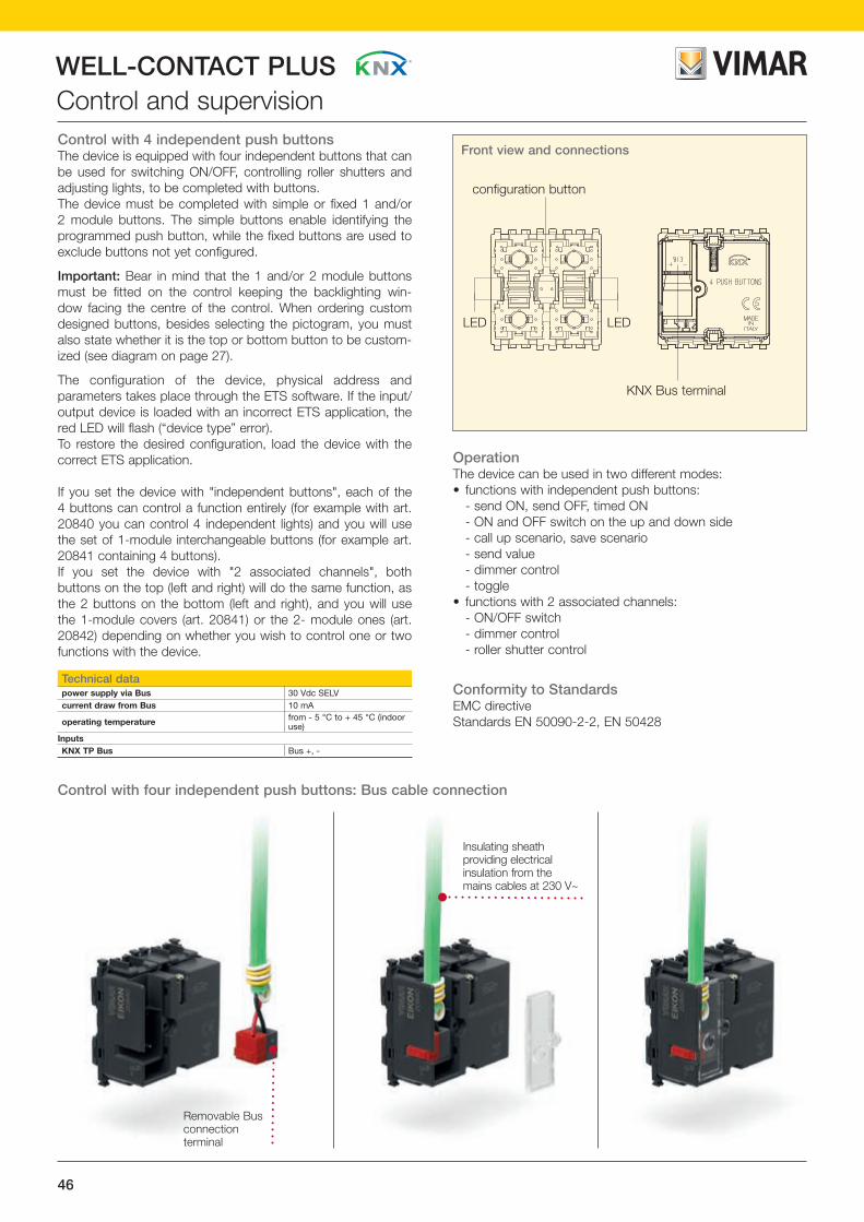
46
WELL-CONTACT PLUSControl and supervisionControl with 4 independent push buttonsThe device is equipped with four independent buttons that can be used for switching ON/OFF, controlling roller shutters and adjusting lights, to be completed with buttons.The device must be completed with simple or fixed 1 and/or 2 module buttons. The simple buttons enable identifying the programmed push button, while the fixed buttons are used to exclude buttons not yet configured.
Important: Bear in mind that the 1 and/or 2 module buttons must be fitted on the control keeping the backlighting win-dow facing the centre of the control. When ordering custom designed buttons, besides selecting the pictogram, you must also state whether it is the top or bottom button to be custom-ized (see diagram on page 27).
The configuration of the device, physical address and parameters takes place through the ETS software. If the input/output device is loaded with an incorrect ETS application, the red LED will flash (“device type” error). To restore the desired configuration, load the device with the correct ETS application.
If you set the device with "independent buttons", each of the 4 buttons can control a function entirely (for example with art. 20840 you can control 4 independent lights) and you will use the set of 1-module interchangeable buttons (for example art. 20841 containing 4 buttons).If you set the device with "2 associated channels", both buttons on the top (left and right) will do the same function, as the 2 buttons on the bottom (left and right), and you will use the 1-module covers (art. 20841) or the 2- module ones (art. 20842) depending on whether you wish to control one or two functions with the device.
OperationThe device can be used in two different modes:• functions with independent push buttons: - send ON, send OFF, timed ON - ON and OFF switch on the up and down side - call up scenario, save scenario - send value - dimmer control - toggle• functions with 2 associated channels: - ON/OFF switch - dimmer control - roller shutter control
Conformity to StandardsEMC directive Standards EN 50090-2-2, EN 50428
Removable Bus connection terminal
Insulating sheath providing electrical insulation from the mains cables at 230 V~
Control with four independent push buttons: Bus cable connection
Front view and connections
LED LED
configuration button
KNX Bus terminal
Technical datapower supply via Bus 30 Vdc SELVcurrent draw from Bus 10 mA
operating temperature from - 5 °C to + 45 °C (indoor use)
InputsKNX TP Bus Bus +, -

47
WELL-CONTACT PLUS
The drawings of the side views give the overall dimensions and the flush depth in mm
WE
LL-C
ON
TAC
T P
LUS
Control and supervisionControl with 4 independent push buttonsControl with 4 independent push buttons, KNX standard, visible in darkness, to be completed with button - 2 modules
27,5
44,8
49
20
27,2
19 44,7
49
49,8
50
19,5
27,2
EIKON
20840grey
19840grey
ARKÉ
14840white
16840grey
16840.Bwhite
IDEA
PLANA

48
WELL-CONTACT PLUSInterchangeable buttons for control device
2-central-module cover plate
2-central-module mounting frame for flush mounting
Control with 4 independent push buttons
Customized 2-module simple button
Simple button 1 neutral module and with arrows
1-module fixed button
2-module fixed button
Example of 1- and 2-module buttons installation
Note.The simple buttons enable identifying the programmed push button, while the fixed buttons are used to exclude buttons not yet configured.
Eikon Tactil glass cover plate
Home automation control with 6 buttons
The controls are customizable by fixing adhesive labels (art. 21847)
3-module mounting frame
Example Eikon Tactil control installation
NotesThe controls must be customized by fixing an adhesive label (21847) in the designated areas of the device (top and bottom); the symbol is backlit with RGB colours to be set during system programming.
The cover plate must be attached so that the central contacts perfectly match those of the control device 21840 or 21860.

49
WELL-CONTACT PLUS
WE
LL-C
ON
TAC
T P
LUS
Interchangeable buttons for control deviceFor articles in the white version: add .B to the code of the article in the grey version.For articles in the Next version: add .N to the code of the article in the grey version.
2-module control device 1-module interchangeable button 2-module interchangeable button
Simple20840
Simple button
Blank20841
“O” symbol20841.0
“I” symbol20841.1
Blank20842
“O” symbol20842.0
“I” symbol20842.1
“I/O” symbol20841.2
With directional arrows 20841.3
With regulation symbol20841.4
“I/O” symbol20842.2
With directional arrows 20842.3
With regulation symbol20842.4
Fixed button
Blank20843
Blank20844
PLANA For articles in the Silver version: add .SL to the code of the article in the white version.
2-module control device 1-module interchangeable button 2-module interchangeable button
Simple14840
Simple button
Blank14841
“O” symbol14841.0
“I” symbol14841.1
Blank14842
“O” symbol14842.0
“I” symbol14842.1
“I/O” symbol14841.2
With directional arrows14841.3
With regulation symbol 14841.4
“I/O” symbol14842.2
Wth directional arrows14842.3
With regulation symbol14842.4
Fixed button
Blank14843
Blank14844
IDEA For articles in the white version: add .B to the code of the article in the grey version.
2-module control device 1-module interchangeable button 2-module interchangeable button
Simple16840
Simple button
Blank16841
“O” symbol16841.0
“I” symbol16841.1
Blank16842
“O” symbol16842.0
“I” symbol16842.1
“I/O” symbol16841.2
With directional arrows 16841.3
With regulation symbol16841.4
“I/O” symbol16842.2
With directional arrows 16842.3
With regulation symbol16842.4
Fixed button
Blank16843
Blank16844
ARKÉ For articles in the white version: add .B to the code of the article in the grey version.
2-module control device 1-module interchangeable button 2-module interchangeable button
Simple19840
Simple button
Blank19841
“O” symbol19841.0
“I” symbol19841.1
Blank19842
“O” symbol19842.0
“I” symbol19842.1
“I/O” symbol19841.2
With directional arrows 19841.3
With regulation symbol19841.4
“I/O” symbol19842.2
With directional arrows 19842.3
With regulation symbol19842.4
Fixed button
Blank button19843
Blank button19844
EIKON
B1
B2
A1
A2
B1
B2
A1
A2
mezzo tasto superiore
mezzo tasto inferiore
14 mm 14 mm
7 m
m
7 m
m
A1 and A2:customizable area (14x7 mm).
B1 and B2:LED backlighting translucent window.
Note.The 1 or 2 module button must always be fitted keeping the window facing the centre of the control.When selecting the pictogram you must specify whether the button is top or bottom.
Half top button
Half bottom button
Customizable area of the 1- and 2-module-button

50
WELL-CONTACT PLUSCustomization
64 65 66 67 68 69 70 71 72 73 74
75 76 77 78 79 80 81 82 83 84
88 89 90 91 92 93 94 95 96
97 99 100 101 102 103 104 10598 106 107
85
86 87
140 141 142 143 144138 139108 109
110 111 112 113 114 115 116 117 118 119 120
121 122 123 124 125 126 127 128 129 130
134 135 136 137 138 139 140 141 142
143 144 145 146 147 148 149 150 151 152 153
154 155
131
132 133
156 157
01 02 03 04 05 06 07 08 09 1110
12 13 14 15 16 17 18 19 20 21 22apre
23avanti
24bagno
25cantina
26chiude
27esterno
28garage
29generale
30 31giardino indietro
32 33
34 35 36 37
luce OFF
ON ripostiglio scale solaio38
terrazza49
alarm50
110 111
108 109
do notdisturb
112 114113 115 116 117 118 119 120
121 122
51 52
54 55 56 57 58 59 60 61
22 23avanti
24bagno
25cantina
26chiude
27 28garage
29generale
30
31indietro
32 33 34 35 36 37luce OFF ON ripostiglio scale solaio
38 39 40 41terrazza
4942alarm
50 123 124 125 126 127 128
129 130 131
do notdisturb
62 63
5351 52
apre esterno giardino
132 133 134 135 136 137
64 65
Libraries of standard lettering and symbols for buttons ( symbols already contemplated on push buttons in catalogue)
IDEA
ARKÉ
PLANA
EIKON

51
WELL-CONTACT PLUS
WE
LL-C
ON
TAC
T P
LUS
CustomizationCustomizing Eikon Tactil devicesInstructions for customisation• The controls must be customized by fixing an adhesive label (21847) in the des-
ignated areas of the device (top and bottom);• The labels contain the most common symbols for identifying the controls. Some
pictograms, for the most commonly used controls in traditional and home auto-mation electrical systems, are repeated several times (see table below);
• For Well-contact Plus controls, the symbol is backlit with RGB colours to be set during system programming.
Labels for customizing controlsControl customized by fixing labels
Label
Repetion
Repetion
Repetion
Repetion
Repetion
Repetion
Repetion
Repetion
Repetion
Available symbols in labels code 21847 (Some symbols are repeated)
10 8
3 2 4 5 2 4 1 1 1 3 3
1
1 1 1 1 1 1 1 1 1
1 1 1 1 1 1 2 21 1
1
1
3 3 3 32
2
2 2 2
2
1 1 1 1 1 1 12
2
1 1
111 1 1
1
11
11 1
2
2
2 2
2
2
21 1 1
11 1 1
1
1
2 2
2
1 2 2 2 2 2 2 2 2 2
1
3 3
1 1 1 1 1 125 5

52
WELL-CONTACT PLUSInterchangeable buttons for control devices
Arké 1-module interchangeable buttons19841 .B Four interchangeable buttons, blank19841.0 .B Four interchangeable buttons, O symbol19841.1 .B Four interchangeable buttons, I symbol19841.2 .B Four interchangeable buttons, I O symbol
ARKÉ
19841grey
19841.1grey
19841.Bwhite
19841.1.Bwhite
19841.0grey
19841.2grey
19841.0.Bwhite
19841.2.Bwhite
Idea 1-module interchangeable buttons16841 .B Four interchangeable buttons, blank16841.0 .B Four interchangeable buttons, O symbol16841.1 .B Four interchangeable buttons, I symbol16841.2 .B Four interchangeable buttons, I O symbol
IDEA
16841grey
16841.1grey
16841.Bwhite
16841.1.Bwhite
16841.0grey
16841.2grey
16841.0.Bwhite
16841.2.Bwhite
Eikon 1-module interchangeable buttons20841 .B .N Four interchangeable buttons, blank20841.0 .B .N Four interchangeable buttons, O symbol20841.1 .B .N Four interchangeable buttons, I symbol20841.2 .B .N Four interchangeable buttons, I O symbol
20841grey
20841.1grey
20841.Bwhite
20841.1.Bwhite
20841.NNext
20841.1.NNext
20841.0grey
20841.2grey
20841.0.Bwhite
20841.2.Bwhite
20841.0.NNext
20841.2.NNext
EIKON

53
WELL-CONTACT PLUS
WE
LL-C
ON
TAC
T P
LUS
Interchangeable buttons for control devicesEikon 1-module interchangeable buttons20841.3 .B .N Four interchangeable buttons, direction arrow symbol20841.4 .B .N Four interchangeable buttons, adjustment symbol20843 .B .N Four blank interchangeable fixed buttons
20841.3grey
20841.3.Bwhite
20841.3.NNext
20841.4grey
20843grey
20841.4.Bwhite
20843.Bwhite
20841.4.NNext
20843.NNext
EIKON
Arké 1-module interchangeable buttons19841.3 .B Four interchangeable buttons, direction arrow symbol19841.4 .B Four interchangeable buttons, adjustment symbol19843 .B Four blank interchangeable fixed buttons
19841.3grey
19841.3.Bwhite
19841.4grey
19843grey
19841.4.Bwhite
19843.Bwhite
ARKÉ
Idea 1-module interchangeable buttons16841.3 .B Four interchangeable buttons, direction arrow symbol16841.4 .B Four interchangeable buttons, adjustment symbol16843 .B Four blank interchangeable fixed buttons
IDEA
16841.3grey
16841.3.Bwhite
16841.4grey
16843grey
16841.4.Bwhite
16843.Bwhite

54
WELL-CONTACT PLUSInterchangeable buttons for control devices
Plana 1-module interchangeable buttons14841.3 .SL Four interchangeable buttons, direction arrow symbol14841.4 .SL Four interchangeable buttons, adjustment symbol14843 .SL Four blank interchangeable fixed buttons
PLANA
14841.3white
14841.3.SLSilver
14841.4white
14843white
14841.4.SLSilver
14843.SLSilver
Plana 1-module interchangeable buttons14841 .SL Four interchangeable buttons, blank14841.0 .SL Four interchangeable buttons, O symbol14841.1 .SL Four interchangeable buttons, I symbol14841.2 .SL Four interchangeable buttons, I O symbol
PLANA
14841white
14841.1white
14841.SLSilver
14841.1.SLSilver
14841.0white
14841.2white
14841.0.SLSilver
14841.2.SLSilver

55
WELL-CONTACT PLUS
WE
LL-C
ON
TAC
T P
LUS
Interchangeable buttons for control devices
Arké 2-module interchangeable buttons19842 .B Two interchangeable buttons, blank19842.0 .B Two interchangeable buttons, O symbol19842.1 .B Two interchangeable buttons, I symbol19842.2 .B Two interchangeable buttons, I O symbol
ARKÉ
19842grey
19842.1grey
19842.Bwhite
19842.1.Bwhite
19842.0grey
19842.2grey
19842.0.Bwhite
19842.2.Bwhite
Eikon 2-module interchangeable buttons20842 .B .N Two interchangeable buttons, blank20842.0 .B .N Two interchangeable buttons, O symbol20842.1 .B .N Two interchangeable buttons, I symbol20842.2 .B .N Two interchangeable buttons, I O symbol
20842grey
20842.1grey
20842.Bwhite
20842.1.Bwhite
20842.NNext
20842.1.NNext
20842.0grey
20842.2grey
20842.0.Bwhite
20842.2.Bwhite
20842.0.NNext
20842.2.NNext
EIKON
Eikon 2-module interchangeable buttons20842.3 .B .N Two interchangeable buttons, direction arrow symbol20842.4 .B .N Two interchangeable buttons, adjustment symbol20844 .B .N Two blank interchangeable fixed buttons
EIKON
20844grey
20844.Bwhite
20844.NNext
20842.3grey
20842.3.Bwhite
20842.3.NNext
20842.4grey
20842.4.Bwhite
20842.4.NNext

56
WELL-CONTACT PLUSInterchangeable buttons for control devicesArké 2-module interchangeable buttons19842.3 .B Two interchangeable buttons, direction arrow symbol19842.4 .B Two interchangeable buttons, adjustment symbol19844 .B Two blank interchangeable fixed buttons
19842.3grey
19842.3.Bwhite
19842.4grey
19844grey
19842.4.Bwhite
19844.Bwhite
ARKÉ
Idea 2-module interchangeable buttons16842.3 .B Two interchangeable buttons, direction arrow symbol16842.4 .B Two interchangeable buttons, adjustment symbol16844 .B Two blank interchangeable fixed buttons
IDEA
16842.3grey
16842.3.Bwhite
16842.4grey
16844grey
16842.4.Bwhite
16844.Bwhite
Idea 2-module interchangeable buttons16842 .B Two interchangeable buttons, blank16842.0 .B Two interchangeable buttons, O symbol16842.1 .B Two interchangeable buttons, I symbol16842.2 .B Two interchangeable buttons, I O symbol
IDEA
16842grey
16842.1grey
16842.Bwhite
16842.1.Bwhite
16842.0grey
16842.2grey
16842.0.Bwhite
16842.2.Bwhite

57
WELL-CONTACT PLUS
WE
LL-C
ON
TAC
T P
LUS
Interchangeable buttons for control devicesPlana 2-module interchangeable buttons14842 .SL Two interchangeable buttons, blank14842.0 .SL Two interchangeable buttons, O symbol14842.1 .SL Two interchangeable buttons, I symbol14842.2 .SL Two interchangeable buttons, I O symbol
PLANA
14842white
14842.1white
14842.SLSilver
14842.1.SLSilver
14842.0white
14842.2white
14842.0.SLSilver
14842.2.SLSilver
Plana 2-module interchangeable buttons14842.3 .SL Two interchangeable buttons, direction arrow symbol14842.4 .SL Two interchangeable buttons, adjustment symbol14844 .SL Two blank interchangeable fixed buttons
PLANA
14842.3white
14842.3.SLSilver
14842.4white
14844white
14842.4.SLSilver
14844.SLSilver
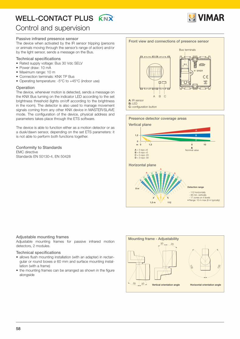
58
WELL-CONTACT PLUSControl and supervisionPassive infrared presence sensorThe device when activated by the IR sensor tripping (persons or animals moving through the sensor’s range of action) and/or by the light sensor, sends a message on the Bus.
Technical specifications• Rated supply voltage: Bus 30 Vdc SELV• Power draw: 10 mA• Maximum range: 10 m• Connection terminals: KNX TP Bus• Operating temperature: -5°C to +45°C (indoor use)
OperationThe device, whenever motion is detected, sends a message on the KNX Bus turning on the indicator LED according to the set brightness threshold (lights on/off according to the brightness in the room). The detector is also used to manage movement signals coming from any other KNX device in MASTER/SLAVE mode. The configuration of the device, physical address and parameters takes place through the ETS software.
The device is able to function either as a motion detector or as a dusk/dawn sensor, depending on the set ETS parameters: it is not able to perform both functions together.
Conformity to StandardsEMC directiveStandards EN 50130-4, EN 50428
Front view and connections of presence sensor
A B C
Bus terminals
A: IR sensorB: LEDC: configuration button
Adjustable mounting framesAdjustable mounting frames for passive infrared motion detectors, 2 modules.
Technical specifications• allows flush mounting installation (with an adapter) in rectan-
gular or round boxes ø 60 mm and surface mounting instal-lation (with a frame)
• the mounting frames can be arranged as shown in the figure alongside
Presence detector coverage areas
Vertical plane
Horizontal plane
1,2
0
A = 3 fasci +6B = 6 fasci +0C = 5 fasci -20D = 3 fasci -30
Copertura volumetrica
• Angolo solido esplorato: - 112 orizzontale - 36 verticale minimo - 17 settori su 4 piani• Portata: 10 m max (8 m tipico)
1,5 8m
0
B
A
CD
112
B
BB B
B
BC
D D
A C CA
C
C
A
1,5 m
8 m
D
10
Portata nominale
1,2
0
A = 3 fasci +6B = 6 fasci +0C = 5 fasci -20D = 3 fasci -30
Copertura volumetrica
• Angolo solido esplorato: - 112 orizzontale - 36 verticale minimo - 17 settori su 4 piani• Portata: 10 m max (8 m tipico)
1,5 8m
0
B
A
CD
112
B
BB B
B
BC
D D
A C CA
C
C
A
1,5 m
8 m
D
10
Portata nominale
A = 3 rays +6B = 6 rays +0C = 5 rays -20D = 3 rays -30
Detection range
- 112 horizontally - 36 min. vertically - 17 zones on 4 levels• Range: 10 m max (8 m typically)
Nominal value
30 20
135 135
30 20
Orientabilità verticale Orientabilità orizzontale
Mounting frame - Adjustability
Vertical orientation angle Horizontal orientation angle

59
WELL-CONTACT PLUS
The drawings of the side views give the overall dimensions and the flush depth in mm
WE
LL-C
ON
TAC
T P
LUS
Control and supervision
43,7
25,5 44,8
49
26
43,8
49,8
50
26,5
43,5
44,8
49
114
114
85,6 63
114
114
85,6 63
114
114
85,6 63
EIKON
EIKON
20850grey
00802.14grey
20850.NNext
00802.20Next
20850.Bwhite
00802white
14850white
00802white
19850grey
00802.14grey
14850.SLSilver
00802.20Silver
19850.Bwhite
00802white
44,7
49
37
19,7
16850grey
16836grey
16850.Bwhite
16836.Bwhite
IDEA
IDEA
PLANA
PLANA
ARKÉ
ARKÉ
Presence detectorPassive infrared presence detector, KNX standard - 2 modules
Adjustable mounting frameAdjustable mounting frame – 2 modules
85,6 39
114

60
WELL-CONTACT PLUSAccessories for adjustable mounting frames
16831
16836
16935
16831
20636
20485
Example of surface mounting
Eikon Idea Plana
14636
14485
16831.01
Fixing frame for adjustable surface mounting frames
Example of flush mounting
Eikon Idea Plana
Adapter for fixing adjustable flush mounting frames
20637 16830 14637
20636 16836 14636

61
WELL-CONTACT PLUS
The drawings of the side views give the overall dimensions and the flush depth in mm
WE
LL-C
ON
TAC
T P
LUS
Accessories for adjustable mounting frames
14,5
79,5
44,8
49
36,5
46
44,8
49
36,5
46
37,5
Adapter for fixing adjustable flush mounting framesAdapter for fixing adjustable flush mounting frames
Fixing frame for adjustable surface mounting framesFixing frame for surface mounting
14,5
79,5
14,5
79,5
14,5
79,5
EIKON
EIKON
00805.14grey
00800.14grey
00805.20Next
00800.20Next
00805white
00800white
00805white
00800white
00805.14grey
00800.14grey
00805.20Silver
00800.20Silver
00805white
00800white
16831grey
16830grey
16831.Bwhite
IDEA
IDEA
PLANA
PLANA
ARKÉ
ARKÉ
44,8
49
36,5
46

62
WELL-CONTACT PLUSAccess controlTouch transponder card readers for outside the roomThis device, to be completed with Eikon Tactil cover plate art. 21666.., enables controlling entry with transponder cards to the rooms where it is installed outside the room. The transponder reader is provided with two relays to control the door lock, to control a courtesy light, or for other uses; the device is moreover provided with two inputs for connecting electrical equipment of the ON / OFF type (for example to control the switch for door opening and closing, a magnetic contact for signalling windows open or closed, ceiling pull alarm, etc.).On the front of the reader there are four LEDs each of which associated with an icon for signalling the following states:- Access (entry allowed or entry denied);- Guest status (room occupied or do not disturb); - Call status (rescue request with bathroom ceiling pull-cord, room service call, etc.);- Services status (make up room, etc.).In guest status, call status and services status, the colour of the LED can be set during configuration.The reader is equipped with a bell identified by a low-lit LED (if the feature is enabled to activate a timed KNX relay); in this case, too, the colour of the LED is programmable.The device is also able to signal insertion and removal of the cover plate (it switches one of its KNX communication objects ON in the event of removal).The transponder reader is able to dialogue with other EIB/KNX components.For cleaning the cover plate, simply bring near the card enabled with service access: after card recognition the bell will be disabled for 30 s.IMPORTANT: Do not install the device on the outside (for example, in a common entry to a building).
Technical specifications• supply voltage: - Bus: 29 V SELV; - 12-24 V ~ ± 20% SELV;• Power draw: - on the bus: 10 mA - on the supplementary power supply (at 12-24 V ~): 130 mA max• Terminals: - TP bus; - supplementary power supply (12-24 V ~); - digital inputs for 2 NO or NC contacts (with no potential,
SELV); - outputs for 2 NO relays (24 V~ SELV 4 A cos 1; 24 V~
SELV 2 A cos 0.6);• Operating temperature: -5 °C - +45 °C (inside)• This device contains only SELV circuits that must be kept
separate from circuits with dangerous voltage.
OperationThe configuration of the reader, physical address and parameters (NO or NC contacts inputs, normal or timed relay outputs, LED colour, bell enabling, brightness of the LED associated with the bell icon, etc.) takes place via the ETS software.The card is read by putting it in front of the reader that in sequence checks:- “system code” (whether consistent);- “date” field (if enabled, it checks whether the validity has expired);- “password” (checks all the codes associated with it and enabled, such as guest code, service code, timeframes).IMPORTANT: The transponder readers should be powered separately from all other loads (electric locks, lamps, contactors, etc.) using a transformer 16887 dedicated to them whose outputs will be used solely for the readers.
Important: The length of the cable for connecting the inputs must not exceed 30 m.N.B. In the phase of installation provide for cable connection lengths that allow extracting the device from the flush mounting box so as to be able to access the configuration button.For the 12-24 V~ power supply use 12/24 Vdc power supplies or transformers with secondary winding having extra low voltage (SELV) for continuous service; do not use the voltage transformers for doorbells.
Conformity to StandardsR&TTE directiveStandards EN 50491, EN 50428, EN 300 330-2, EN 301 489-3
• Configuration BUTTON: button for switching between normal mode or programming mode or detecting the physical address.
• LED off: signalling "normal operation." • Red LED on steady: “addressing mode” indicator (the LED goes out
automatically after programming the physical address)
Connections Configuration button
LED
C NO
C NO
Relay 1
Relay 2
Power supply 12-24 V ~
IN1
IN2
Common inputs 1 and 2
BUS line
Front view
LED STATUS• LED 1:- steady green: signalling “Entry allowed” (the LED remains illuminated for approxi-
mately 3 s).- blinking green: signalling if the timeframe is not valid (the LED blinks for approxi-
mately 3 s). - steady red: signalling “Entry denied” (the LED remains illuminated for approxi-
mately 3 s).- blinking red: signalling if the expiry date is not valid.- steady amber: signalling if the system coding is not valid. - blinking amber: signalling if the day of the week is not valid.- blinking red/green: synchronize the device's internal clock.
• LED 2: signalling “Room service call.”• LED 3: signalling “Do not disturb.”• LED 4: signalling “Make up room.”• LED 5: on - identifying bell. The brightness is low and becomes high on touching
the button.
Note.The meaning taken on by the LEDs depends on the subjects of communication (therefore the functions) that are configured in the reader with the ETS software.
LED 5
LED 2
LED 3
LED 4
LED 1
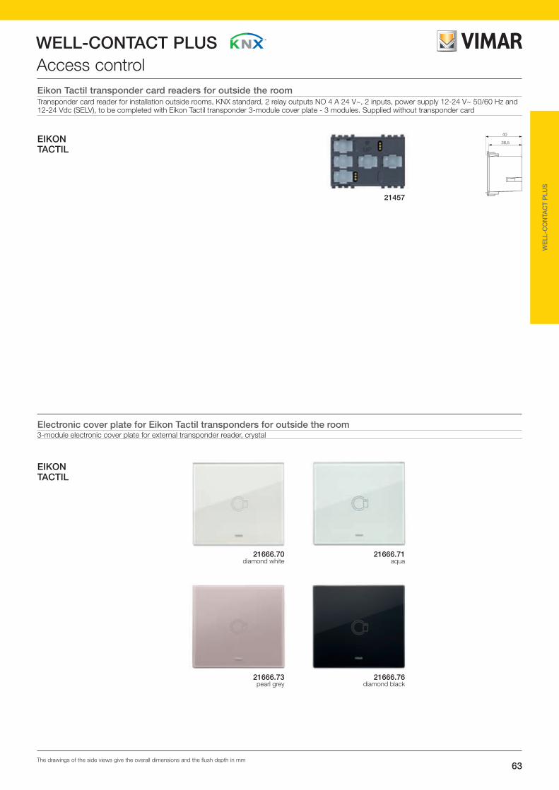
63
WELL-CONTACT PLUS
The drawings of the side views give the overall dimensions and the flush depth in mm
WE
LL-C
ON
TAC
T P
LUS
Access control
EIKON TACTIL
EIKON TACTIL
21457
Eikon Tactil transponder card readers for outside the roomTransponder card reader for installation outside rooms, KNX standard, 2 relay outputs NO 4 A 24 V~, 2 inputs, power supply 12-24 V~ 50/60 Hz and 12-24 Vdc (SELV), to be completed with Eikon Tactil transponder 3-module cover plate - 3 modules. Supplied without transponder card
21666.71aqua
21666.76diamond black
21666.70diamond white
21666.73pearl grey
Electronic cover plate for Eikon Tactil transponders for outside the room3-module electronic cover plate for external transponder reader, crystal
40
36,5

64
WELL-CONTACT PLUSAccess control
Front viewTransponder card readers for outside the roomThe device, with transponder cards, enables controlling entry to the rooms where it is installed externally.The transponder reader is provided with two relays to control the door lock, to control a courtesy light, or for other uses; the device is moreover provided with two inputs for connecting electrical equipment of the ON / OFF type (for example to control the switch for door opening and closing, a magnetic contact for signalling windows open or closed, ceiling pull alarm, etc.).On the front of the reader there are four LEDs each of which associated with an icon for signalling the following states:• access (entry allowed or entry denied);• guest status (room occupied or do not disturb);• call status (rescue request with bathroom ceiling pull-cord,
room service call, etc.);• services status (make up room, etc.).The transponder reader is able to dialogue with other KNX components.
Technical specifications• Bus supply voltage: 30 Vdc SELV• auxiliary supply voltage: 12-24 V ± 20% SELV• consumption: 10 mA on the Bus; 130 mA max on the
supplementary power supply 12-24 V• Terminals: - KNX TP Bus - supplementary power supply (12-24 V ) - digital inputs for 2 NO or NC contacts (with no potential, SELV) - outputs for 2 NO relays (24 V~ SELV 4 A cos 1; 24 V~ SELV 2 A cos 0.6)• maximum distance of the input contact from the device:
30 m with twisted cable• this device contains only SELV circuits that must be kept
separate from circuits with dangerous voltage• Operating temperature: -5°C - +45°C (indoor use only, do not install outside, for example in the
common entry to a building).
OperationThe configuration of the reader, physical address and parameters (NO or NC contact inputs, one-, two-position stable or timed relay outputs, etc.) is done with the ETS software. If the transponder reader is loaded with an incorrect ETS application, both the red LED on the back of the device and the front LEDs 2, 3 and 4 will blink (“device type” error). To restore the desired configuration, load the device with the correct ETS application.The card is read by putting it in front of the reader that in sequence checks:• “system code” (whether consistent);• “date and time” field (if enabled, it checks whether the validity
has expired);• “password” (checks all the codes associated with it and
enabled, such as guest code, service code, timeframes).The device is able to store up to 2000 cards simultaneously.
With ETS it is possible to set the following parameters (can be selected directly from the graphic windows):• card information;• device configuration;• general settings;• configuration of channels;• inputs A and B;• outputs A and B.
Conformity to StandardsR&TTE directiveStandards EN 50090-2-2, EN 50428, EN 300 330-2, EN 301 489-3
LED STATUSLED 1:- cannot be controlled via ETS or Bus.- steady green: signalling “Entry allowed” (the LED remains illuminated for
approximately 3 s).- blinking green: signalling if the timeframe is not valid (the LED blinks for
approximately 3 s). - steady red: signalling “Entry denied” (the LED remains illuminated for
approximately 3 s).- blinking red: signalling if the expiry date is not valid.- steady amber: signalling if the system coding is not valid- blinking amber: signalling if the day of the week is not valid.- blinking red/green: synchronize the device's internal clock.LED 2: - red: signalling "Do Not Disturb". - blinking red: signalling "Room occupied".LED 3: amber - signalling “Room service call.”LED 4: green - signalling “Make up room.”
Note.The meaning taken on by the LEDs 2, 3 and 4 depends on the subjects of communication (therefore the functions) that are configured in the reader with the ETS software. For all the applications in which the device is configured with different functions and LED indications to the standard ones, the customer can ask Vimar to customize the symbols on the front of the reader with a laser. "Steady LED" operation has priority over its prior blinking, if any.
• Configuration BUTTON: button for switching between normal mode or programming mode or detecting the physical address.
• LED off: signalling “normal operation”.
• Red LED: “addressing mode” indicator (the LED goes out automatically after programming the physical address).
Alimentazione12 -24 V ~
Ingresso1
Ingresso2
Relè 1
LED
PULSANTEconfigurazione
C NO
Comuneingressi1 e 2
LineaBUSRelè 2
C NO
Connections
Configuration BUTTON
Relay 1
Input 1
Input 2 Bus line
Relay 1
Power supply 12-24 V ~
Common inputs
1 and 2

65
WELL-CONTACT PLUS
The drawings of the side views give the overall dimensions and the flush depth in mm
WE
LL-C
ON
TAC
T P
LUS
Access control
46,5
67,3
49
37
Transponder card readers for outside the roomTransponder card reader for installation outside rooms, KNX standard, 2 relay outputs NO 4 A 24 V~, 2 digital inputs, power supply 12-24 V~ 50/60 Hz and 12-24 Vdc (SELV) - 3 modules. Supplied without transponder card
EIKON
20457grey
20457.NNext
20457.Bwhite
19457grey
19457.Bwhite
ARKÉ67,2
49
47,1
37
14457white
14457.SLSilver
16927grey
16927.Bwhite
IDEA
PLANA

66
WELL-CONTACT PLUSAccess control
Illuminated pocket
Front viewTransponder card reader with pocket for inside roomThe device enables checking for the presence in the room of the guest or the service staff by unambiguously identifying the transponder card inserted. The reader with pocket is provided with two relays that can be configured to control the door lock, to control a courtesy light, to optimize power consumption or for other uses too; the device is moreover provided with two inputs for connecting electrical equipment of the ON / OFF type (for example to control the switch for door opening and closing, a magnetic contact for signalling windows open or closed, ceiling pull alarm, etc.). The device is able to dialogue with other KNX components.
Technical specifications• Bus supply voltage: 30 Vdc SELV• auxiliary/supplementary rated supply voltage: -12-24 V ±
20% SELV• consumption: 10 mA on the Bus, 130 mA max on the
supplementary power supply (at 12-24 V )• Terminals: - TP bus - supplementary power supply (12-24 V ); - digital inputs for 2 NO or NC contacts (with no potential, SELV) - outputs for 2 NO relays (24 V~ SELV 4 A cos 1; 24 V~ SELV 2 A cos 0.6)• maximum distance of the input contact from the device:
30 m with twisted cable• this device contains only SELV circuits that must be kept
separate from circuits with dangerous voltage• Operating temperature: -5°C - +45°C (indoor use only, do not install outside, for example in the
common entry to a building).
OperationThe configuration of the reader, physical address and parameters (NO or NC contact inputs, normal or timed relay outputs, etc.) is done with the ETS software.If the reader with a pocket is loaded with an incorrect ETS application, the pocket backlighting and the red LED on the back will blink (“device type” error).To restore the desired configuration, load the device with the correct ETS application. The card is read by putting it into the special pocket that is always illuminated when there is no card in it. After inserting the card, the device checks the following in sequence:• “system code” (whether consistent)• “date and time” field (if enabled, it checks whether the validity
has expired);• “password” (checks all the codes associated with it and
enabled, such as guest code, service code, timeframes).The device is able to store up to 2000 cards simultaneously.
With ETS it is possible to set the following parameters (can be selected directly from the graphic windows):• card information;• device configuration;• general settings;• configuration of channels;• inputs A and B;• outputs A and B.
Conformity to StandardsR&TTE directiveStandards EN 50090-2-2, EN 50428, EN 300 330-2, EN 301 489-3
POCKET LIGHTING
On: The card is not inserted.
Off: The card is inserted.
Blinking slowly or always off: The card is not recognized and therefore the functions are not activated.
Blinking fast: Synchronize the device’s internal clock.
Configuration BUTTON: button for switching between normal mode or programming mode or detecting the physical address.
LED off: signalling “normal operation”.
Red LED: “addressing mode” indicator (the LED goes out automatically after programming the physical address).
Alimentazione12 -24 V ~
Ingresso1
Ingresso2
Relè 1
LED
PULSANTEconfigurazione
C NO
Comuneingressi1 e 2
LineaBUSRelè 2
C NO
Connections
Configuration BUTTON
Relay 1
Input 1
Input 2 Bus line
Relay 1
Power supply 12-24 V ~
Common inputs
1 and 2

67
WELL-CONTACT PLUS
The drawings of the side views give the overall dimensions and the flush depth in mm
WE
LL-C
ON
TAC
T P
LUS
Access control
49
67,337
56,5
74,8
50,2
56,5
36,5
67,3
49
56,5
37
EIKON
20453grey
20453.NNext
20453.Bwhite
19453grey
19453.Bwhite
ARKÉ67,3
49
56,7
37
14453white
14453.SLSilver
16923grey
16923.Bwhite
IDEA
PLANA
Transponder card reader with pocket for inside roomTransponder card reader with vertical pocket for installation inside rooms, KNX standard, 2 relay outputs NO 4 A 24 V~, 2 digital inputs, additional power supply 12-24 V~ 50/60 Hz and 12-24 Vdc (SELV) - 3 modules

68
WELL-CONTACT PLUSAccess control
Front view Transponder card reader/programmer with vertical pocket in table mounting box The device enables programming and coding the transponder cards to use with the readers 20457, 16927, 14457 and the pockets 20453, 16923 and 14453 (in the respective colour variations). The reader/programmer must be connected to a personal computer on which the Well-contact Suite software must be installed for creating and managing the necessary data for the configuration of the cards according to the different require-ments. The device is equipped with a cable for connecting the USB port of the PC and a backlit pocket for signalling card reading/writing. It is mounted on a tilted desktop box and needs no driver.
Technical specifications• power supply: from USB port (5 Vdc)• consumption: 130 mA• connection: USB 1.1 or higher cable for connection to PC • this device contains only SELV circuits that must be kept
separate from circuits with dangerous voltage • Operating temperature: -5 °C - +45 °C (indoor use)• not compatible with the old Well-contact system
NoteThe device is supplied by the PC via the USB port; therefore, in the phase of sizing the system (number of necessary power supplies), you must not take account of the consumption of the device.
OperationProgramming takes place by inserting the transponder card (that can be blank or already used previously) into the reader pocket after having selected the writing command with the PC software.If, 30 s after the command, no card is inserted into the pocket, the programming command is cancelled and the PC is sent a message telling it that the device is awaiting data.The cards are read in a similar manner; the card is inserted into the pocket of the device that will read the saved data (codes, passwords, etc.) and will transmit them to the PC. The reader/programmer enables programming and/or reading the following data:• “System code” (that identifies the installation or the name of
the hotel or the site where the system is installed); • “Password” (of the client or service);• “Date and time” (day/month/year).
Conformity to StandardsR&TTE directiveStandards EN 55022, EN 55024, EN 300 330-2, EN 301 489-3
Transponder card customizing The card can be customized on the back with colour or black and white graphics.
Technical specifications• Mifare® at 13.56 MHz (1 k ISO 14443 with 16 sectors of 64
bytes)• free memory banks for multi-applications (e.g. money)• 7 access levels (e.g., guest, service, etc.)• not compatible with the old Well-contact system
POCKET LIGHTINGOn: the card is inserted Off the card is not inserted Blinking (for approximately 3 s): during the programming phase
Eikon
Idea
Connections
Plana

69
WELL-CONTACT PLUS
The drawings of the side views give the overall dimensions and the flush depth in mm
WE
LL-C
ON
TAC
T P
LUS
Access control
88,8 148,6
74,9
111 121,6
77,4
142,5
74,4
89,2
01598
Transponder card 01598 Programmable transponder card for readers inside and outside the room, customizable back (rear)
EIKON
20450grey
20450.NNext
20450.Bwhite
19450grey
19450.Bwhite
ARKÉ 90,3 148,6
82,6
14450white
14450.SLSilver
16920grey
16920.Bwhite
IDEA
PLANA
Transponder card reader/programmerTransponder card reader/programmer with vertical pocket in table mounting box, 3 modules for Idea, 4 modules for Eikon, Arké and Plana. To complete with Classica 3-module cover plate for Idea, 4 modules for Eikon (Classic and Round) and 4 modules for Plana

70
WELL-CONTACT PLUSTemperature controlKNX electronic thermostatA device for controlling ambient temperature (heating / air-conditioning) in 2 or 4-pipe systems with a "boost" function according to stage and neutral zone; it can interact with other thermostats and with a supervision centre (PC with Well-contact Suite software). It can manage 2 temperature zones completely independently (equivalent to two thermostats A and B). For each zone the heating/air-conditioning modes are managed according to the relative reference temperature. It is equipped with a relay programmable as NC or NO that can be used for general use (e.g. lighting, closing zone solenoid valve, activating electric towel warmer, etc.) or to control speed 1 of the fan coil, which is managed by thermostat A or thermostat B. It also has a digital input programmable as NC or NO, which can be used for other applications such as detecting an open window. The thermostat is equipped with an RGB display and 6 capacitive buttons for controlling the temperature set point and the speed of the fan coil, the configuration of the modes of operation of the thermostat and adjustment of the colour of the display.
Technical specifications• RGB backlit touch display with configurable colours• Possibility of connecting an external temperature NTC sen-
sor (20432, 19432, 14432 or 02965): maximum length of the cable connecting the sensor to the devices: 60 m. Use a twisted cable with a minimum cross-section of 0.5 mm2 (01840)
• Possibility of using the temperature values measured by 8 dif-ferent sensors connected to the KNX Bus (DPT_Value_Temp data)
• Room humidity display• Digital input for NO or NC contact (with no potential, SELV)• The maximum distance between the input contact and the
thermostat is 30 m• Main functions:
- room temperature set point adjustment (within the limits set by reception)
- fan coil speed adjustment• this device contains only SELV circuits that must be kept
separate from circuits with dangerous voltage
ConfigurationThe configuration of the thermostat, physical address, param-eters, its operation, etc., is done with the ETS software.If the thermostat is loaded with an incorrect ETS application, the red LED on the back of the device will flash and all the LCD segments will blink on the display (“device type” error). To restore the desired configuration, load the device with the correct ETS application. The user, by means of the front buttons, will be able to change the temperature set point and the speed of the fan-coil; changing these parameters forces the thermostat onto manual operation. With ETS it is possible to set the following parameters (can be selected directly from the graphic windows):• general settings • temperature sensor• temperature setpoint• setpoint temperature• input and output• adjustment• valve• fan coil speed• scenarios
Conformity to StandardsEMC directive, Standard EN 50428, EN 50491
Technical datapower supply via KNX Bus 29 Vdc SELVcurrent draw from KNX Bus 10 mA
reading accuracy- ≤ ±0.5°C between +15°C and +30°C- ≤ ±0.8°C at the extremes
operating temperature from - 5 °C to + 45 °C (indoor use)
InputsKNX TP Bus EIB + -programmable digital input 1, 2
external temperature sensor(20432, 19432, 14432, 02965)
Outputs
NO relay 24 V~ SELV 4 A cosϕ 1; 24 V~ SELV 2 A cosϕ 0.6 NC, C
02952 - Front view and connections
Configuration button
InputCommon input
CRelay
NO
KNX Bus line
LED
External temperature sensor terminals
Room temperature
Heating
Operation setup button
Fan coil setting button
Up/increase button
Down/decrease button
Ambient humidity
Fan-coil speed

71
WELL-CONTACT PLUS
The drawings of the side views give the overall dimensions and the flush depth in mm
WE
LL-C
ON
TAC
T P
LUS
Temperature control
49
44,826,5
36EIKONARKÉPLANA
02952.Bwhite
02952grey
KNX electronic thermostatTouch electronic thermostat for ambient temperature control (heating and air conditioning) of 2 independent zones, KNX standard home automation system, 1 NO relay output 4 A 24 V~, 1 input for electronic temperature sensor or wired temperature sensor, 1 programmable digital input, RGB LED backlighting, to be completed with Eikon, Arké or Plana cover plates - 2 modules

72
WELL-CONTACT PLUSTemperature controlElectronic thermostatA device for controlling ambient temperature (heating / air-conditioning); it can interact with other thermostats and with a supervision centre (PC with Well-contact Suite software). It can manage 2 temperature zones completely independently (equivalent to two thermostats A and B). For each zone the heating/air-conditioning modes are managed according to the relative reference temperature. It is equipped with a relay pro-grammable as NC or NO that can be used for general use (e.g. lighting, closing zone solenoid valve, activating electric towel warmer, etc.) or to control the valve of the fan coil, which is managed by thermostat A and thermostat B. It also has a digital input programmable as NC or NO, which can be used for other applications such as detecting an open window. The device is equipped with a display and four front buttons to control the temperature set-point and the speed of the fan-coil.
Technical specifications• this device contains only SELV circuits that must be kept
separate from circuits with dangerous voltage • digital input for NO or NC contact (clean, SELV); max distance
between the input contact and the thermostat: 30 m;• input for temperature sensor (20432, 19432, 14432); maxi-
mum length of the cable connecting the sensor to the devic-es: 60 m. Use a twisted cable with a minimum cross-section of 0.5 mm2 (01840)
• relay output NO ( 24 V~ SELV 4 A cos 1; 24 V~ SELV 2 A cos 0.6);
• temperature sensors that can be managed by the thermostat:- internal NTC- possibility of connecting an external NTC (20432, 19432,
14432)• possibility of using the temperature values measured by 8 dif-
ferent sensors connected to the KNX Bus• the user can manually change the setpoint using buttons A
and B only in “comfort” mode.
ConfigurationThe configuration of the thermostat, physical address, param-eters, its operation, etc., is done with the ETS software. If the thermostat is loaded with an incorrect ETS application, the red LED on the back of the device will flash and all the LCD seg-ments will blink on the display (“device type” error). To restore the desired configuration, load the device with the correct ETS application. The user, by means of the front buttons, will be able to change the temperature set point and the speed of the fan-coil; changing these parameters forces the thermostat onto manual operation. With ETS it is possible to set the following parameters (can be selected directly from the graphic windows):• general settings; • temperature sensor;• temperature setpoint;• setpoint temperature;• input and output;• adjustment;• valve;• fan coil speed;• scenarios.
OperationUsing the thermostat it is possible to set: • the temperature set-point in the room (the change can only be
made within certain limits set by the control centre or recep-tion, etc.);
• the speed of the fan-coil.To change the temperature press the + or – button twice:• on pressing it the first time the display will show the currently
set temperature;• on pressing it the second time the increase/decrease in the
displayed value will begin.
Conformity to StandardsEMC directive, Standard EN 50090-2-2, EN 50428
Thermostat displayRoom temperature Unit of measurement
(Celsius/Fahrenheit)
Air conditioning/Heating
Display of the secondary thermostat (B)
Fan coil speed
Guest out of room function (Stand-by)
AntifreezeSystem off
Operating mode(Manual/Automatic)
Economy
Device locked(cannot be
controlled locally)
ext
THERMOSTAT
OFF
A B C D
Front view and connectionsConfiguration button
Input
Common input
CRelay
NO
BUS line LED
External temperature sensor terminals
Button A: decrease in temperature set-point.Button B: increase in temperature set-point.Button C: selection of the thermostat to display / control (A or B) and display the temperature of the external sensor (20432, 14432) Button D: increase/decrease in the speed of the fan-coil.
Technical datapower supply via KNX Bus 30 Vdc SELVcurrent draw from KNX Bus 10 mA
reading accuracy - ≤ ±0.5°C between +15°C and +30°C- ≤ ±0.8°C at the extremes
clock error - ≤ ± 1 s a day
operating temperature from - 5 °C to + 45 °C (indoor use)
InputsKNX TP Bus EIB + -programmable digital input 1, 2
external temperature sensor (20432, 19432, 14432)
Outputs
relay NO 4 A 24 V~ NO, C

73
WELL-CONTACT PLUS
The drawings of the side views give the overall dimensions and the flush depth in mm
WE
LL-C
ON
TAC
T P
LUS
Temperature controlElectronic thermostatElectronic thermostat for ambient temperature control (heating and air conditioning) of 2 independent zones, KNX standard, 1 NO relay output 4 A 24 V~, 1 input for temperature sensor 20432, 1 programmable digital input - 2 modules
EIKON
∆ 20430grey
∆ 20430.NNext
∆ 20430.Bwhite
∆ 14430white
∆ 19430grey
∆ 14430.SLSilver
∆ 19430.Bwhite
49,8
50
36,5
47,6
44,8
49
36
48,3
44,9
49
37
47,2
48
37 44,7
49
IDEA
PLANA
ARKÉ
16915grey
16915.Bwhite
∆ Available until stocks last

74
WELL-CONTACT PLUSTemperature control
Temperature sensorDevice for use with centralized controller 21509 and the touch screen 21554, 21511, 21512, 20511.1, 19511 and 14511.1 to view the ambient temperature where the products are installed.
Technical specifications• Maximum length of cable connecting sensor to devices: 60 m
Resis
tenza K
Ω
0-50
50
100
150
200
250
300
350
400
50 100
NTC_min
NTC_nominale
NTC_max
150
Temperatura °C
20432 - resistance / temperature graph
Technical dataresistance Bus 29 Vdccurrent draw 42 mAdissipated power 15 mWoperating temperature from - 40 °C to + 125 °C
KNX weather stationThe weather station integrates with the Well-contact Plus sys-tem for managing temperature control, energy and automation systems. The KNX weather station measures quantities such as temperature, wind speed, rainfall, and brightness whose values can be used, based on the limits, to control the device control outputs; the states can then be associated with each other by using the AND and OR logic gates of the weather station.
Main functions:• Brightness measurement: this function can be used to turn
on the outside lights at dusk and turn them off at dawn.• Wind measurement: the strength of the wind is measured
electronically and is therefore quiet and reliable even in the event of hail, snow and sub-zero temperatures. The weather station is also able to detect whirlwinds and updraughts. This function activates awning rewinding in windy conditions or when there is precipitation.
• Rainfall measurement: the weather station is equipped with a sensor with a heated surface so that only the raindrops and snowflakes (and therefore not fog or dew) are measured as precipitation. In case of rain, you can disable automatic irriga-tion. Once it has stopped raining or snowing, the sensor dries quickly and the precipitation message is turned off.
• Temperature measurement: the weather station measures the value of the current ambient temperature.
• Control outputs for all values: the limit values can be set via the respective parameters or via the ETS communication objects.
• 8 AND logic gates and 8 OR logic gates each one with 4 inputs: the control operations themselves as well as the 8 logic inputs (in the form of communication objects) can be used as inputs for the AND and OR logic gates; the output of each gate can be configured as 1 bit or as 2 x 8 bits.
Technical specifications• Configuration button;• CONFIGURATION LED;• Protection class: IP44;• dimensions: 96x77x118 mm (W x H x D);• Weight: approximately 170 g.
ConfigurationThe weather station functions and parameters are configured via the ETS software; the program file (in VD format), the manual and the technical info sheet are available for download in the Software->Product Software section of the website www.vimar.com.
Conformity to StandardsEMC directive, Standard EN60730-1, EN 50491
Technical dataAUX power supply 12-32 V , 12-24 V~ SELVcurrent draw max, ripple 10% 100 mAgroup addresses 254 maxpossible associations 255 maxcommunication objects 109rain sensor heating 1.2 Wtemperature measurement range from -40°C to 80°Ctemperature definition 0.1°C
temperature accuracy 1°C with -10°C - +85°C1.5°C with -25°C - +150°C
wind measurement range 0 - 70 m/swind definition <10% of the reading
wind accuracy with an angle of incidence of 45° and mounting on dedicated support
25% with 0 - 15 m/s
brightness measurement range 0 - 150,000 Lux
brightness definition 1 Lux with 0-120 Lux2 Lux with 121-1,046 Lux63 Lux with 1,047-52,363 Lux423 Lux with 52,364-150,000 Lux
brightness accuracy 35%
operating temperature from -30°C to + 50°C (outdoor use)
Inputspower supply +, -Bus TP bus;
AUX
12-32 Vdc
12-24 Vac
AUX+,-
L N L N
Bus+,-
Bus +, -
01
89
0
01500
01546 - Connections
KNX power supply unit:art. 01500
AUX power supply unit:art. 01830
or transformer: art. 16887

75
WELL-CONTACT PLUS
The drawings of the side views give the overall dimensions and the flush depth in mm
WE
LL-C
ON
TAC
T P
LUS
Temperature control
Weather station01546 Weather station, KNX standard, power supply 12-32 Vdc or 12-24 Vac
01546
Installation
Base with cable ties supplied
20432.Bwhite
14432white
19432grey
20432grey
20432.NNext
14432.SLSilver
19432.Bwhite
22,3
49
24,434,7
34,7
23,4 22,3
49
35,2
24,4 22,2
49
EIKON
PLANA
ARKÉ
Temperature sensorElectronic temperature sensor, 1 output
Wired temperature sensorWired temperature sensor, cable length 4 m
02965

76
WELL-CONTACT PLUSSystem components01521 - Actuator for fluorescent lampsThe actuator is able to activate electrical applications (alternat-ing or three-phase current) via 12 independent potential-free contacts; control is via the Bus or via the dedicated manually operated switches. The devices are powered by the KNX Bus and do not require an external power supply.
Technical specifications• Bus output voltage: 30 Vdc SELV • power outputs: 12 Floating contacts • switch voltage: 250/440 V ~ • rated current: 10AX EN 60669; 10A (AC1) EN 60947-4• operating temperature: -5 °C - + 45 °C (inside)• protection rating: IP20• 12 modules of 17,5 mm
OperationThe physical address and the parameter settings are set using the Engineering Tool Software ETS.Programming LED Lights up red when the device is operated in programming mode (after pressing the Programming button).
Conformity to StandardsLV directive, EMC Directive, Standard EN 50090-2-2
01525 - Actuator for 8 roller shuttersThe actuator for shutters/Venetian blinds controls independent drives at 230 V~ for sunblind applications via the KNX Bus and it is also possible to control ventilators, doors and windows. The devices are bus-powered and do not require an external auxiliary power supply; the output contacts are electro-mechanically inter-locked in such a way as to protect the drives from any damage.
Technical specifications• Bus output voltage: 30 Vdc SELV • independent outputs each for up to 2 drives in parallel operation• rated voltage UN: 230 V ~ 50/60 Hz • rated current IN: 6 A• operating temperature: -5 °C - + 45 °C (inside)• protection rating: IP20• 8 modules of 17,5 mm
OperationThe physical address and the parameter settings are set using the Engineering Tool Software ETS.Programming LED Lights up red when the device is operated in programming mode (after pressing the Programming button).
01521 - Front view and connections
1: Label carrier2: Programming key3: Programming LED, red4: Connecting terminal KNX5: Switch position display and ON/OFF operation6: Load current circuit, each with 2 screw terminals
10 AX250/440 V
01521VIMAR
01525 - Front view
1: Bus connecting terminal2: Programming key3: Programming LED (red)
4: Label carrier5: Connection terminals and
Conformity to StandardsLV directive, EMC Directive, Standard EN 50090-2-2
Connection for rolling shutter and venetian blind drives Connection for ventilators/switch function

77
WELL-CONTACT PLUS
The drawings of the side views give the overall dimensions and the flush depth in mm
WE
LL-C
ON
TAC
T P
LUS
System components
01521
01525
Actuator for fluorescent lamps01521 Actuator with 12 10 A 250 V~ 50/60 Hz relay outputs for fluorescent lamps, KNX standard, installation on DIN rail (60715 TH35),
occupies 12 17,5 mm modules
Actuator for 8 roller shutters01525 Actuator for 8 roller shutters, 6 A 230 V~ 50/60 Hz relay outputs, KNX standard, installation on DIN rail (60715 TH35), occupies 8
17,5 mm modules

78
WELL-CONTACT PLUSSystem components01544 - KNX DALI gatewayThe gateway enables controlling DALI devices (eg electronic ballasts, transformers, etc.). It is equipped with 8 independent channels on which you can connect up to 16 DALI devices per channel; for individual channels or all the channels you can en-able your choice of switching functions, dimming, fixed value, fault signalling, Lamp stabilization time, and functions relating to lighting scenarios. There is no need for separate DALI start-ups or manually assigning addresses for DALI devices.
Technical specifications• Operating voltage: 85-265 V ~ 50/60 Hz, 110-240 Vdc• DALI outputs: 8 in compliance with IEC 60929• Number DALI devices: Max. 16 per output• Line length:Max. 300 m (line cross-section 1,5 mm2)• Operating temperature: -5 °C - + 45 °C (inside)• Protection rating: IP20• 6 modules of 17,5 mm
OperationNo special commissioning is necessary for the DALI devices. After connection of the operating voltage, the DALI Gateway au-tomatically recognises the DALI operating devices connected.The assignment of the physical address and the setting of the parameters are performed with the ETS. Programming LED Lights up red when the device is operated in programming
mode (after pressing the Programming button).
Conformity to StandardsLV directive, EMC Directive, Standard EN 50090-2-2
01547 - KNX IP interfaceThe IP/KNX interface enables the switching of KNX telegrams in IP telegrams on Ethernet network. The data can be exchanged between KNX system and IP network.
Technical specifications• operating voltage: - Bus: 30 Vdc SELV - additional: 12-30 Vdc, 12-24 V~• consumptions: - on the Bus: 5 mA - additional power supply: 190 mA• terminals: - TP Bus - additional power supply - IP RJ45 connector 10/100 BaseT, IEEE 802.3• operating temperature: -5 °C - + 45 °C (inside)• protection rating: IP20 • 2 modules of 17,5 mm
OperationThe assignment of the physical address and the setting of the parameters are performed with the ETS.
Conformity to StandardsEMC DirectiveStandard EN 50090-2-2
01544 - Front view and connections
max. 16 EVG
L3
L1N
L2
PE
max. 16 EVG
L
1817
NUs
DALION
A2 3 4
B1
DA- DA+ DA- DA+
C6 7 8
D5
DA- DA+ DA- DA+
E10 11 12
F9
DA- DA+ DA- DA+
G14 15 16
H13
DA- DA+ DA- DA+
Us = 85 ... 265 V~110 ... 240 V
9
1
2
3
4
8
57 6
1: Nameplate support2: KNX Programming key3: KNX Programming LED, red4: KNX Connecting terminal5: DALI LED, yellow
6: Operating LED, green7: Operating voltage8: DALI outputs, 2 screw terminals each9: TEST key

79
WELL-CONTACT PLUS
The drawings of the side views give the overall dimensions and the flush depth in mm
WE
LL-C
ON
TAC
T P
LUS
System components
01544
01547
KNX DALI gateway01544 KNX DALI gateway, 8-channel for 16 lamps per channel, installation on DIN (60715 TH35) rail, occupies 6 17,5 mm modules
KNX IP interface01547 KNX IP interface, installation on DIN (60715 TH35) rail, occupies 2 17,5 mm modules
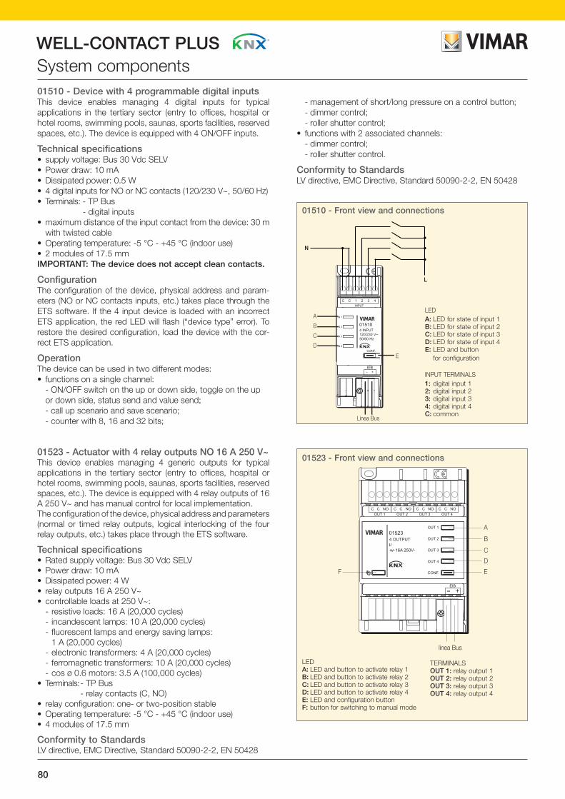
80
WELL-CONTACT PLUSSystem components
01510 - Front view and connections
4 INPUT120/230 V~50/60 Hz
E
Linea Bus
A
B
C
D
01510
IN 1
IN 2
IN 3
IN 4
EIB- +
INPUT
CONF.
L
N
LEDA: LED for state of input 1 B: LED for state of input 2 C: LED for state of input 3 D: LED for state of input 4 E: LED and button for configuration
INPUT TERMINALS 1: digital input 12: digital input 23: digital input 34: digital input 4C: common
01510 - Device with 4 programmable digital inputsThis device enables managing 4 digital inputs for typical applications in the tertiary sector (entry to offices, hospital or hotel rooms, swimming pools, saunas, sports facilities, reserved spaces, etc.). The device is equipped with 4 ON/OFF inputs.
Technical specifications• supply voltage: Bus 30 Vdc SELV• Power draw: 10 mA• Dissipated power: 0.5 W• 4 digital inputs for NO or NC contacts (120/230 V~, 50/60 Hz) • Terminals: - TP Bus - digital inputs • maximum distance of the input contact from the device: 30 m
with twisted cable• Operating temperature: -5 °C - +45 °C (indoor use)• 2 modules of 17.5 mmIMPORTANT: The device does not accept clean contacts.
ConfigurationThe configuration of the device, physical address and param-eters (NO or NC contacts inputs, etc.) takes place through the ETS software. If the 4 input device is loaded with an incorrect ETS application, the red LED will flash (“device type” error). To restore the desired configuration, load the device with the cor-rect ETS application.
OperationThe device can be used in two different modes: • functions on a single channel: - ON/OFF switch on the up or down side, toggle on the up
or down side, status send and value send; - call up scenario and save scenario; - counter with 8, 16 and 32 bits;
- management of short/long pressure on a control button; - dimmer control; - roller shutter control;• functions with 2 associated channels: - dimmer control; - roller shutter control.
Conformity to StandardsLV directive, EMC Directive, Standard 50090-2-2, EN 50428
01523 - Front view and connections
A
B
C
D
EF
linea Bus
OUT 1
OUT 1C C NO C C NO C C NO C C NO
OUT 2 OUT 3 OUT 4
OUT 2
OUT 3
OUT 4
CONF.
EIB
015234 OUTPUT
16A 250V˜
µ
LEDA: LED and button to activate relay 1 B: LED and button to activate relay 2 C: LED and button to activate relay 3 D: LED and button to activate relay 4 E: LED and configuration button F: button for switching to manual mode
TERMINALSOUT 1: relay output 1 OUT 2: relay output 2 OUT 3: relay output 3 OUT 4: relay output 4
01523 - Actuator with 4 relay outputs NO 16 A 250 V~This device enables managing 4 generic outputs for typical applications in the tertiary sector (entry to offices, hospital or hotel rooms, swimming pools, saunas, sports facilities, reserved spaces, etc.). The device is equipped with 4 relay outputs of 16 A 250 V~ and has manual control for local implementation.The configuration of the device, physical address and parameters (normal or timed relay outputs, logical interlocking of the four relay outputs, etc.) takes place through the ETS software.
Technical specifications• Rated supply voltage: Bus 30 Vdc SELV• Power draw: 10 mA• Dissipated power: 4 W• relay outputs 16 A 250 V~• controllable loads at 250 V~: - resistive loads: 16 A (20,000 cycles) - incandescent lamps: 10 A (20,000 cycles) - fluorescent lamps and energy saving lamps: 1 A (20,000 cycles) - electronic transformers: 4 A (20,000 cycles) - ferromagnetic transformers: 10 A (20,000 cycles) - cos ø 0.6 motors: 3.5 A (100,000 cycles) • Terminals: - TP Bus - relay contacts (C, NO) • relay configuration: one- or two-position stable • Operating temperature: -5 °C - +45 °C (indoor use) • 4 modules of 17.5 mm
Conformity to StandardsLV directive, EMC Directive, Standard 50090-2-2, EN 50428

81
WELL-CONTACT PLUS
WE
LL-C
ON
TAC
T P
LUS
System components
01510
Device with 4 programmable digital inputs01510 Device with 4 programmable digital inputs for NO, NC contacts, 120-230 V~, KNX standard, installation on DIN rail (60715 TH35),
occupies 2 modules size 17.5 mm
01523
Actuator with 4 relay outputs NO 16 A 250 V~01523 Actuator with 4 relay outputs NO 16 A 250 V~, KNX standard, installation on DIN rails (60715 TH35), occupies 4 modules size 17.5 mm

82
WELL-CONTACT PLUSSystem components01522 - Input/output deviceThis device enables managing 4 inputs and 4 generic outputs for typical applications in the tertiary sector (entry to offices, hospital or hotel rooms, swimming pools, saunas, sports facilities, reserved spaces, etc.). The device is equipped with 4 ON/OFF inputs and 4 relay outputs of 16 A 250 V~ and has manual control for local implementation.
Technical specifications• supply voltage: Bus 30 Vdc SELV• Power draw: 10 mA• Dissipated power: 4 W• 4 digital inputs for NO or NC contacts (with no potential,
SELV)• relay outputs 16 A 250 V~• controllable loads at 250 V~: - resistive loads: 16 A (20,000 cycles) - incandescent lamps: 10 A (20,000 cycles) - fluorescent lamps and energy saving lamps: 1 A (20,000 cycles); and electronic transformers: 4 A (20,000
cycles) - ferromagnetic transformers: 10 A (20,000 cycles) - cos 0.6 motors: 3.5 A (100,000 cycles)• Terminals: - TP bus - relay contacts (C, NO) - digital inputs • relay configuration: one- or two-position stable • maximum distance of the input contact from the device: 30 m
with twisted cable• Operating temperature: -5 °C - +45 °C (indoor use)• 4 modules of 17.5 mm
Conformity to StandardsLV Directive, EMC DirectiveStandards EN 50090-2-2, EN 50428
01522 - Front view and connections
Linea Bus
A
B
C
D
E
F
G
H
I
L
OUT 1 OUT 2 OUT 3 OUT 4
OUT 1IN 1
IN 1 IN 2 IN 3 IN 4 EIB
IN 2
IN 3
IN 4
OUT 2
OUT 3
OUT 4
CONF.
015224 IN / 4OUT
16A 250V˜
µ
C C NO C C NO C C NO C C NO
LEDA: state of input 1 B: state of input 2 C: state of input 3 D: state of input 4 E: button for switching to manual
mode F: LED and button to activate relay 1 G LED and button to activate relay 2H LED and button to activate relay 3 I LED and button to activate relay 4L LED and configuration button
TERMINALS OUT 1: relay output 1OUT 2: relay output 2OUT 3: relay output 3OUT 4: relay output 4IN 1: 1 common and 1 digital inputIN 2: 1 common and 1 digital inputIN 3: 1 common and 1 digital inputIN 4: 1 common and 1 digital input
01524 - Front view and connections
LEDA: LED and buttons to activate relay 1 B: LED and buttons to activate relay 2 C: LED and configuration button D: button for switching to manual mode
TERMINALSOUT 1: relay output 1 OUT 2: relay output 2
01524BLINDACTUATOR
OUT 1
OUT 2
CONF.
16A 250V˜
µ
EIB
OUT 1C C
OUT 2
Bus line
C C
A
B
CD
01524 - Actuator for two roller shuttersDevice to control 2 roller shutters, motorized sunblinds and Venetian blinds with adjustable slats.The device is equipped with 2 relay outputs of 16 A 250 V~ and has manual control for local implementation.
Technical specifications• Rated supply voltage: Bus 30 Vdc SELV• Power draw: 10 mA• Dissipated power: 4 W • relay outputs 16 A 250 V~• controllable loads at 250 V~: - cos ø 0.6 motors: 3.5 A (100,000 cycles) • Terminals: - TP bus - relay contacts: 2 (, , NO) - : closed if you press the button - : closed if you press the button - C: common• Operating temperature: -5 °C - +45 °C (indoor use)• 4 modules of 17.5 mm
Conformity to StandardsLV Directive, EMC DirectiveStandards EN 50090-2-2, EN 50428

83
WELL-CONTACT PLUS
WE
LL-C
ON
TAC
T P
LUS
System components
01522
Input/output device01522 Input/output device, 4 relay outputs NO 16 A 250 V~, 4 inputs for NO contacts, KNX standard, installation on DIN rails (60715 TH35),
occupies 4 modules size 17,5 mm
01524
Actuator for two roll-up blinds01524 Actuator for 2 roller shutters with relay outputs 16 A 250 V~, KNX standard, installation on DIN rails (60715 TH35), occupies 4 modules
size 17,5 mm

84
WELL-CONTACT PLUSSystem components01528 - Dimmer 1-10 VThe dimmer is used to control and adjust the brightness of light circuits via the KNX Bus. The device has 2 independent chan-nels; for each channel there is a ground potential contact to control the power circuits. Together with the light sensor 01530, the appliance can be used as a constant brightness dimmer. The dimmer can be connected with up to 2 light sensors. The dimming telegrams are converted into 0…10 V signals corre-sponding to the brightness 0…100%. Art. 01528 works pas-sively, that is the outputs 1…10 V behave as controlled resistors and the connected electronic ballasts (EVG) provide the current. With the exception of the KNX bus voltage, the dimmer requires no external power supply; the setting of the nominal rating for the light dimmer can be performed separately for each channel or as a MASTER / SLAVE combination.N.B. If you do not use sensors 01530, it is necessary to exclude their control from the ETS parameters of the dimmer 01528.
Technical specifications• supply voltage: Bus 30 Vdc SELV • Dissipated power: 250 mW• switchover outputs: 2 clean contacts• cut-in voltage: 250/440 V~, 50/60 Hz• peak current at cut-in: 400 A (150 μs)/320 A (250 μs)/200 A (600 μs) • control outputs: 2, passive 1.... 10 V• connectable load: 100 mA per command output (max 100 m
with 1.5 mm² cable, max 70 m with 0.8 mm² cable) • controllable load: up to a maximum of 50 ballasts• LED loads can be controlled only if equipped with driver 1...10 V• Operating temperature: +5 °C - + 45 °C (inside)• protection class IP20• 4 modules of 17.5 mm
Conformity to StandardsLV Directive, EMC DirectiveStandard EN 50090-2-2
01528 - Front view and connections
BALLAST BALLAST
7
6
5
8
9
4
32
1
01530 - Brightness sensorThe device detects the brightness in the room and, through the connection with the KNX dimmer 01528, keeps the level of brightness in the rooms constant, combining the natural light and the artificial light, thus obtaining the greatest savings and optimizing energy consumptions. It must be installed in a standard box and fixed with a cover using screws.
Technical specifications• inputs for light sensor 01530: 2• adjustment range: optimized on the typical value of 500 lux
You can make 2 sensors 01530 work on the same OUT as 01528 to which they are connected, and maybe use the other OUT as a normal dimmer without the brightness control.
Conformity to StandardsEMC directiveStandard EN 50090-2-2
01530 – Assembly diagram
1: identification plate2: configuration button3: Red configuration LED4: Bus connection terminals5: operating status and manual
operation ON/OFF (if set to "1" it no longer considers the Bus commands)
6: power circuit7: control circuits 1....10 V8: light sensor inputs 015309: light sensor 01530

85
WELL-CONTACT PLUS
WE
LL-C
ON
TAC
T P
LUS
System componentsDimmer01528 Dimmer, 2 inputs for 01530, 2 relay outputs NO 16 A 250 V~, 2 outputs 1-10 V, KNX standard, installation on DIN rails (60715 TH35),
occupies 4 modules size 17.5 mm
01528
01530
Brightness sensor01530 Brightness sensor for dimmer 01528, for ceiling installation

86
WELL-CONTACT PLUSSystem components01529 - IR presence detectorThe detector enables controlling and adjusting lighting and/or HVAC systems depending on brightness and/or movement. The device is for use solely in enclosed spaces such as, for example, offices, schools or private buildings; it cannot be used as an anti-intrusion detector as it is not equipped with anti-tampering.
Technical specifications• Bus output voltage: 24 Vdc, <12 mA • switch-on time after switch-off (programmable): 1 s • adjustable brightness range: 1-1000 lux• opening angle for brightness measurement: 60° • operating temperature: -5 °C - + 45 °C (inside)• protection rating: IP20
OperationThe physical address and the parameter settings are set using the Engineering Tool Software ETS.Programming LED Lights up red when the device is operated in programming mode (after pressing the Programming button).
Conformity to StandardsLV directive, EMC Directive, Standard EN 60669-2-1
01529 - Front view
1: Red configuration LED under zone C of the lens2: Programming buttonA, B, C, D: Sectors that can be individually deactivated
1
2
D A
C B
01529 - Rear view
1: Interface for commissioning adaptor (Updates) 5-pole update cable required
2: Bus connection KNX3: Retaining clamps for enclosed support ring4: Label area for physical address
4
1
3
2

87
WELL-CONTACT PLUS
The drawings of the side views give the overall dimensions and the flush depth in mm
WE
LL-C
ON
TAC
T P
LUS
System componentsIR presence detector01529 IR presence detector, 360° motion range, for lightings depending on the brightness, 0-100 Lux adjustable brightness range, KNX standard,
for ceiling installation
01529
01529.S
Adapter for IR presence detector01529.S Adapter for 01529 IR presence detector with brightness sensor for ceiling installation

88
WELL-CONTACT PLUSSystem components01515 - Interface with 4 programmable channelsThe device is equipped with 4 channels that can be configured as inputs or outputs with the ETS software. The connecting cables with pins approximately 30 cm long permit connecting conventional controls, contacts with zero potential and LEDs. The contact interrogation voltage and the supply voltage for the LEDs are available on the device. The additional resistors for the external light emitting diodes are integrated in the same device. The connection to the Bus is made with the terminal block for connection to the Bus.
Technical specifications• Rated supply voltage: Bus 30 Vdc SELV• inputs/outputs: 4 configurable as input or output • input: - detection voltage: 20 V pulsating - input current: 0.5 mA • output: - supply voltage: 3...5 Vdc - output current: max 2 mA limited by additional
resistors (to control LED 5 V, 2 mA)• protection against overload and polarity reversal• terminals: - TP bus; - terminal block with 6 connection cables 30 cm long• inputs for voltage free contacts• protection class: IP20• Operating temperature: -5 °C - +45 °C (indoor use)
OperationThe configuration of the device, physical address and parameters takes place through the ETS software.
Conformity to StandardsEMC directiveStandards EN 50090-2-2
01515 - Front view and connections
A: Red LED and configuration buttonB: inputs/outputs: 6 conductors with pinC: Bus connection terminals
Terminals:1: common terminal when driving a LED with contacts 1-2-3-42: common terminal when connecting a key/button with contacts 1-2-3-43: IN/OUT 14: IN/OUT 25: IN/OUT 36: IN/OUT 4
01515
A B
C
01526 – Dimmer 230 V~ 50/60 HzThe dimmer is able to control two groups of lamps, each with a maximum power of 300 W. The device has two independ-ent output channels; if only one channel is in operation, the connected power increases up to 500 W. Thanks to the low minimum power of 2 W, the dimmer is suited for connecting different types of lamps. Operation is possible of incandescent lamps, 230 V halogen lamps or low-voltage halogen lamps con-nected to electronic or conventional transformers. The type of load is identified automatically if this is set in the parameters. The two channels are independent and can be connected to dif-ferent phases and serve different types of load. The configura-tion of the device, physical address and parameters takes place through the ETS software.
Technical specifications• supply voltage: Bus 30 Vdc SELV • power consumption: 4.5 W• output power: 300 W/VA (max 500 W if only one channel is
used)• minimum load: 2 W• terminals: - TP bus; - phase 1, neutral, load 1 - phase 2, neutral, load 2• Operating temperature: -5 °C - + 45 °C (inside)• protection class: IP20• 4 modules of 17.5 mm
N.B. Device is not suitable for controlling fluorescent, neon or LED loads.
Conformity to StandardsLV Directive, EMC DirectiveStandards EN 50090-2-2, EN 50428
01526 - Front view and connections
1: power supply: possibility of connecting separate phases 2: input/output terminals for connection to the load 3: identification plate 4: Red LED and configuration button5: Bus connection terminals
01526
1
2
3
5
4

89
WELL-CONTACT PLUS
WE
LL-C
ON
TAC
T P
LUS
System components
01515
Interface with 4 programmable channels01515 Interface with 4 channels that can be programmed as inputs or outputs for LEDs, KNX standard
01526
Dimmer 230 V~ 50/60 Hz01526 Dimmer 230 V~ 50/60 Hz for 2x300 W incandescent lamps, 2x300 VA ferromagnetic transformers, 2x300 VA electronic transformers,
KNX standard, installation on DIN rails (60715 TH35), occupies 4 modules size 17.5 mm

90
WELL-CONTACT PLUSSystem components
01500
01500 - Power supply with 30 Vdc Bus outputPower supply unit for bus systems equipped with decoupling coil. If there are 30 or more Bus devices installed near to each other (for instance in 10-15 m of cable or in the same electric panel), it is advisable to install the power unit near to these devices.The maximum distance between the power supply unit and the furthest device must not exceed 350 m. The power unit is self-protected against short circuits (thanks to a voltage and current dimmer) and ensures a power supply even in the event of brief mains failures provided they do not exceed 200 ms.It is recommended to always have a safety switch for the electric power supply circuit of the device 01500.
Technical specifications• supply voltage: 230 V~ 50/60 Hz ± 10%• Power draw: 200 mA max• Dissipated power: 4 W• Bus output voltage: 30 Vdc SELV • total max output current: 320 mA• short-circuit current: 1 A• Operating temperature: -5 °C - + 45 °C (inside)• 4 modules of 17.5 mm
ConnectionsThe connection to the Bus is made directly from the Bus terminals on the front of the device. The power unit must be installed so that the text is clearly visible and correctly decipherable (Bus polarity reversal). To “Reset” the power unit, remove the bus
connection terminals and, after approximately 20 seconds, put them back in place. The Bus line is connected to the power supply again and the Bus devices return to their predefined initial conditions.
01501.1 - Power supply with 30 Vdc Bus outputPower supply unit for bus systems equipped with decoupling coil.Each bus line needs at least one power unit; if the voltage on the bus is less than 21 V it is necessary to install a second power unit at a distance of at least 200 m from the first one.If there are 30 or more bus devices installed near to each other (for instance in 10-15 m of cable or in the same electric panel), it is advisable to install the power unit near to these devices.The maximum distance between the power unit and the furthest device must not exceed 350 m.The power unit is moreover equipped with an auxiliary output that supplies a voltage of 30 Vdc that can be used to connect an ad-ditional bus line via a decoupling coil. The power unit is self-protected against short circuits (thanks to a voltage and current dimmer) and ensures a power supply even in the event of brief mains failures provided they do not exceed 200 ms.It is recommended to always have a safety switch for the electric power supply circuit of the device 01501.1.
Technical specifications• supply voltage: 85 ÷ 265 V~ 50/60 Hz• power consumption: 55 W max• power loss: 4 W• Bus output voltage: 30 Vdc SELV• auxiliary output voltage: 30 Vdc SELV• total max output current: 640 mA• operating temperature: -5 °C - +45 °C (inside)• short-circuit current: 1,4 A• protection rating: IP20• 4 modules of 17,5 mm
01500 - Front view and connections
1: LED ON: "normal operation" indicator 2: identification plate 3: power supply terminals: mains 230 V~4: Bus connection terminals
3
1 2
4
01501.1 - Front view
1--> Two-color LED green/red2--> Identification plate 3--> Bus connection terminals 4--> Terminals for connection to the auxiliary output: 30 Vdc 5--> Power supply terminals: mains 85 ÷ 265 V~
1
4
5
2
3

91
WELL-CONTACT PLUS
WE
LL-C
ON
TAC
T P
LUS
System components
01500
01501.1
Power supply unit with 30 Vdc Bus output01500 Power supply unit with Bus output of 30 Vdc 320 mA, power supply 120/230 V~ 50/60 Hz, with decoupling coil, KNX standard,
installation on DIN rail 60715 TH35, occupies 4 modules of 17.5 mm
Power supply unit with 30 Vdc Bus output01501.1 Power supply unit with Bus output of 30 Vdc 640 mA, auxiliary output 30 Vdc, power supply 85 ÷ 265 V~ 50/60 Hz, with decoupling coil,
KNX standard, installation on DIN RAIL 60715 TH35, occupies 4 modules size 17,5 mm

92
WELL-CONTACT PLUSSystem components01504.1 - 01504 - Line couplerThis device permits connecting a number of Bus lines together in order to share and/or transfer the data messages; in addition, it provides electrical separation between the lines and filtering of unnecessary messages. The device manages filter tables that are used to block or let messages pass between the various lines limiting and optimizing the data traffic; these tables are created automatically by the ETS software.The line/field coupler can be used irrespectively as a line cou-pler, field coupler or repeater for all KNX networks.
Technical specifications• supply voltage: - 01504: 30 Vdc SELV - 01504.1: 21-30 Vdc SELV Note: The device must be powered on both sides• Power draw: 10 mA• Operating temperature: +5 °C - +45 °C (indoor use)• 2 modules of 17,5 mm
Conformity to StandardsEMC directiveStandards EN 50090-2-2
01504.1 - Front view
1: LED ON: "normal operation" indicator 2: Main Line LED: data transit on the main line3: Line LED: data transit on the secondary line4: terminals for connection to the Bus of the main line5: terminals for connection to the Bus of the secondary line6: Configuration LED7: configuration button: button for switching between normal mode or
programming mode or detecting the physical address8: identification plate
123
5 4
8
67

93
WELL-CONTACT PLUS
WE
LL-C
ON
TAC
T P
LUS
System componentsLine coupler01504.1 Line coupler, KNX standard, installation on DIN rail (60715 TH35), occupies 2 modules of 17.5 mm
Line coupler∆ 01504 Line coupler, KNX standard, installation on DIN rail (60715 TH35), occupies 2 modules of 17.5 mm
∆ 01504
01504.1
∆ Available until stocks last

94
WELL-CONTACT PLUSSystem components01540 - USB interface type BThis device is used, via the built-in USB port, to connect a per-sonal computer to the Bus line (or Bus lines) to configure, ad-dress, parameterize, display, record and diagnose all the com-ponents of the Bus system. The interface is connected to the PC via the USB port (type B) built into the device and any USB port (type A) of the personal computer or of a HUB. The inter-face is powered by the PC over the USB cable; if this is not con-nected or the personal computer is switched off, the interface is not active and cannot be accessed by the Bus.In addition, the USB interface enables connecting the reception PC for the complete supervision and management of the sys-tem with the Well-contact Suite software.
Note.The USB cable (type A on the PC side and type B on the inter-face side) is not provided.
Technical specifications• supply voltage: Bus 30 Vdc SELV• consumption: 10 mA• Operating temperature: -5 °C - + 45 °C (inside)• 2 modules of 17.5 mm
Conformity to StandardsEMC directiveStandard EN 50090-2-2
1. identification plate 2. button for switching between normal mode or programming mode or
detecting the physical address 3. Configuration LED 4. Bus connection terminals 5. USB LED: data transmission/reception on the USB port 6. KNX LED: data transmission/reception on the Bus 7. USB port
INDICATORSLED 3 on red: “addressing mode” indicator (the LED goes out automatically after programming the physical address)LED 3 off: "normal operation" indicatorUSB LED on green: “USB connected” indicatorKNX LED flashing green: "data in transit on the Bus line" indicator
01540 - Front view and connections
°°
01540
7
65
2
1
3
4
16887 - Transformer for DIN rail (60715 TH35) Transformer in a modular enclosure (3 modules size 17.5 mm) compatible with DIN rail (60715 TH35).
Technical specifications• power supply: 230 V~ 50 Hz• maximum usable power on output 24 V~: 24 VA• maximum usable power on output 12 V~: 12 VA• can be installed on DIN rail (60715 TH35)• 3 modules of 17.5 mm
Conformity to StandardsLV directiveStandard 61558-2-8

95
WELL-CONTACT PLUS
The drawings of the side views give the overall dimensions and the flush depth in mm
WE
LL-C
ON
TAC
T P
LUS
System componentsUSB interface type B01540 USB interface type B, KNX standard, installation on DIN rail (60715 TH35), occupies 2 modules of 17.5 mm
01540
Safety transformer16887 Safety transformer 230/12-24 V~ (SELV) 24 VA, for continuous service, installation on DIN (60715 TH35) rail, it occupies 3 modules size
17.5 mm, grey RAL 7035
16887
01890
Bus cable01890 Cable 2x2x0.8 mm, free of LSZH halogens, KNX standard, green - 100 m

96
WELL-CONTACT PLUSWell-contact Suite softwareWell-contact Suite (WCS) SoftwareTo manage and supervise the Well-contact Plus system, Vimar has created a family of software products to try and satisfy the requests of the different types of systems of its customers. The following table lists the six types of application.
Light: to manage a structure with up to 15 rooms from a single station. Thanks to 5 password levels, control can be customized: the manager of the structure, for example, can access the complete system to supervise, edit the parameters and program the functions, while the receptionist with another password will only access some of these operations.
Basic: to manage a structure with up to 50 rooms from a single station. Thanks to 5 password levels, control can be customized: the manager of the structure, for example, can access the complete system to supervise, edit the parameters and program the functions, while the receptionist with another password will only access some of these operations.It can be interfaced with at most one WCS Client 01592Top: to control large hotels with a potentially limitless number of rooms and stations. This application has 7 password levels and makes it possible to use the planner for supervising arrivals and departures.It can be interfaced with countless WCS Client 01592 stations
Client: application licence enabling you to manage the Basic and Top systems from a limitless number of stations.
Office: dedicated to offices and business structures, it enables managing the functions of a potentially limitless number of rooms from one station. With 7 password levels, control can be targeted and secure. It can be interfaced with countless WCS Client Office 01594 stations
Client Office: Office application licence enabling access to the program from any number of stations.
Management: for interfacing with administration management software (contact Vimar to see if interfacing with the required management software is feasible).
ApplicationsThe WCS software is used to carry out the following operations:• management of bookings (hotel version);• management of the user records;• management of structure personnel records;• management of access by users and personnel to the various
rooms in the structure: creation of the cards for the access control system, management of the transponder readers of the part of the system that deals with access control, creation of lists with access log;
• supervision of the automation system: climate control, activation of electric loads (lights on/off, dimmer lights, relays,…), access control management, alarm management, creation of scenarios, scheduling activation of scenarios, reaction of decisional logic elements, supervision of the E-way emergency lighting system.
As regards managing security when using the Well-contact Suite software, the strategies implemented in the software are listed here:• access to the software allowed only for users previously
configured in the software; • seven levels of software access “privileges” to be associated
with the software users;
• encrypted data communication between the system file server and client systems;
• encrypted “sensitive” data (e.g. software user password);• encrypted data communication between the system and the
card programmer;• use of Mifare® Standard cards.
The main characteristic of the Well-contact Suite software is to automatically create graphic windows in the supervision section. These windows show all the rooms in the hospitality facility with graphic symbols representing the main functions of the automation system devices in the rooms. The rooms are divided according to their use: rooms, common areas, technical areas. For each type of room there are one or more of the following “theme views.” A theme view is a representation of the room highlighting a particular function of the devices in the room.The “theme views” envisaged in the Well-contact Suite software comprise:• the “thermostats” view• the “Guest in room” view• the “windows opening status” view• the “room cleaning status” view
Besides the theme views, a “summary view” is created automatically, in which the room’s main data are shown.
Besides the above-mentioned views, the Well-contact Suite software automatically creates a window with the “detail” view of the room, in which the graphic symbols of the room’s main functions are included; the type of functions automatically presented in the detail view of the room and the related characteristics can be customized according to the particular requirements of the user.In any case, the supervision windows created automatically by the Well-contact Suite software can be customized to collect the user’s requests.
The Well-contact Suite software enables viewing the alarm events created by the Well-contact Plus system to send an alarm “reset” command to the system and create a log for these events. It is lastly possible to define different types of alarm together with the related display priorities.
WCS Gestionali WCS Office Client WCS Office WCS Client WCS Top WCS Basic
WCS Gestionali WCS Office Client WCS Office WCS Client WCS Top WCS Basic
WCS Gestionali WCS Office Client WCS Office WCS Client WCS Top WCS Basic
WCS Gestionali WCS Office Client WCS Office WCS Client WCS Top WCS Basic
WCS Gestionali WCS Office Client WCS Office WCS Client WCS Top WCS Basic
WCS Gestionali WCS Office Client WCS Office WCS Client WCS Top WCS Basic
Zone supervision screen

97
WELL-CONTACT PLUS
WE
LL-C
ON
TAC
T P
LUS
Well-contact Suite software
01597
Well-contact Suite software01589 Well-contact Suite Light software for managing and controlling the Well-contact Plus devices, complete with CD and hardware key
01590 As above, Well-contact Suite Basic
01591 As above, Well-contact Suite Top
01592 As above, Well-contact Suite Client
01593 As above, Well-contact Suite Office
01594 As above, Well-contact Suite Client Office
Supplementary Well-contact Suite software for administration management01595 Supplementary Well-contact Suite software for interfacing with administration management software
(for an up-to-date list of the supported management software, please contact the sales network)
Spare USB key for Well-contact Suite01597 Spare USB key for Well-contact Suite software
015890159001591015920159301594
01595
To order in the event of breakage or malfunctioning of the USB hardware key contained in the package of the articles 01590, 01591, 01592, 01593, 01594. The broken original USB stick must be returned to Vimar.

98
WELL-CONTACT PLUSSoftware and interface01993 - Hardware interface for programming and configuringBy means of 01998 interface, supplied with driver for USB, con-nected to PC, it is possible to use the software for configuring KNX Well-contact Plus touch screens (21848, 20848.1, 19848.1, 14848.1, 21849, 20849, 19849, 16849, 14849). The configura-tion enables adding/modifying rooms, devices, page layout and updating the firmware, downloadable from www.vimar.com.The EasyDraw&EasyCap software suite enable programming and designing systems in CAD style, integrating both the range of By-me devices and that of KNX devices. The 01993 contains the 01947 interface for the By-me system management.
Technical specifications• the software is compatible with the following operating systems: Windows 7 (32 and 64 bit), Windows 8 (32 and 64 bit)• power supply directly from PC via USB port• USB cable with type-A connector for PC connection, 1.8 m
long (supplied)• cable customized and polarized for connecting programming
device, length of cable 1.5 m (supplied)• Operating temperature: 5°C - +40°C• dimensions 115x75x25 mm
OperationThe ON LED comes on when the interface is connected to the computer via the USB cable. During the transmission/reception of the data, the LEDs h and i light up as follows:
• LED h on when the PC receives the data from the specific device;
• LED i on when the PC transmits the data to the specific device.
Conformity to StandardsEMC Directive, Standards EN 55022, EN 55024
Connecting the PC to the touch screens
8-module touch screen
3-module touch screen
01998 interface
01998 - Interface
ON
USB connector for connecting to the PC
Polarized cable for connection to device to program
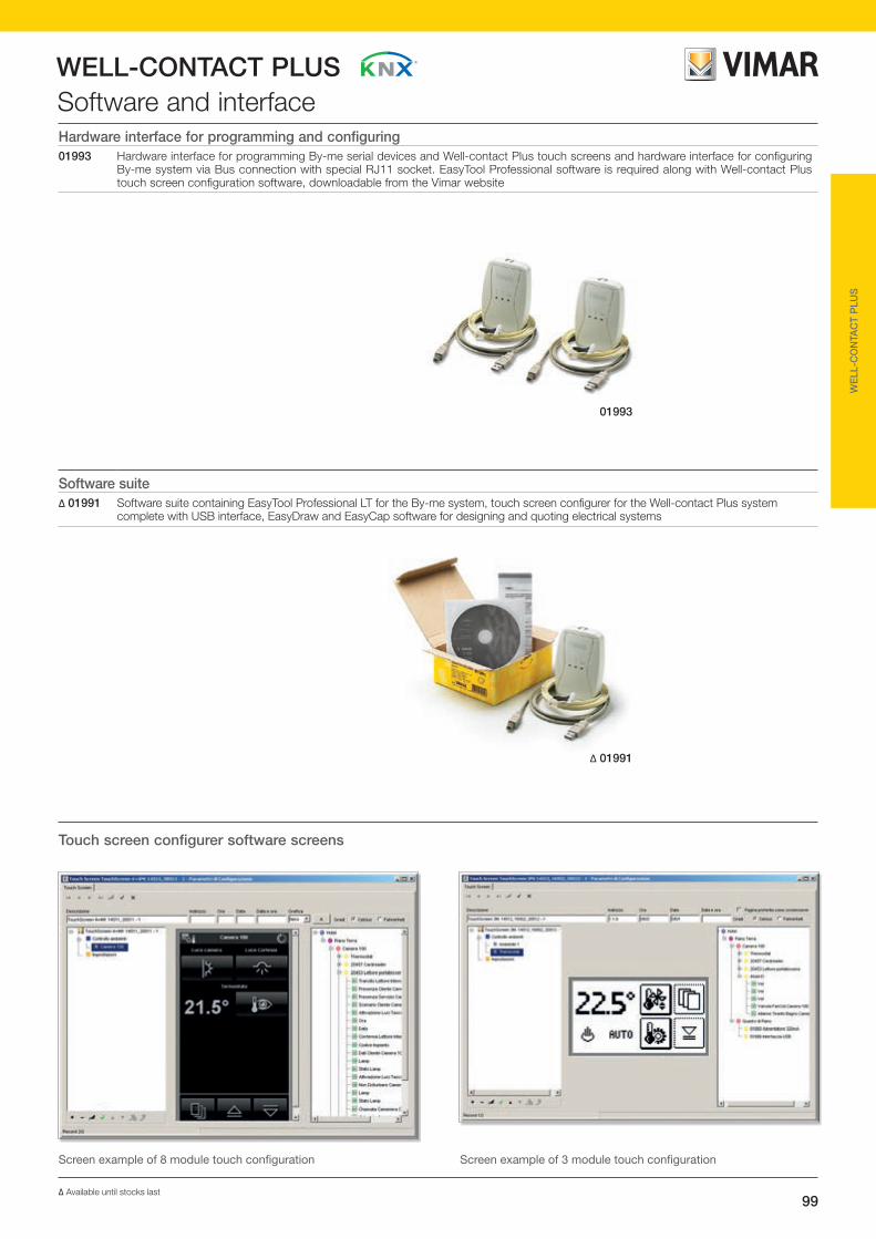
99
WELL-CONTACT PLUS
WE
LL-C
ON
TAC
T P
LUS
Software and interfaceHardware interface for programming and configuring01993 Hardware interface for programming By-me serial devices and Well-contact Plus touch screens and hardware interface for configuring
By-me system via Bus connection with special RJ11 socket. EasyTool Professional software is required along with Well-contact Plus touch screen configuration software, downloadable from the Vimar website
Software suite∆ 01991 Software suite containing EasyTool Professional LT for the By-me system, touch screen configurer for the Well-contact Plus system
complete with USB interface, EasyDraw and EasyCap software for designing and quoting electrical systems
01993
∆ 01991
Touch screen configurer software screens
Screen example of 3 module touch configurationScreen example of 8 module touch configuration
∆ Available until stocks last

100
WELL-CONTACT PLUSInstallation examples
The following examples give some types of hotel and tertiary sector systems; depending on the functions to be implemented, it is necessary to choose not only the devices but above all how these must be configured.
In the case of a hotel room the guest, by putting the card into the transponder reader, enters the room; the device, after recognizing the card, activates the main light in the room and the bed-head courtesy light (example of a scenario) that then will also be able to be commanded by the single buttons. Subsequently the guest inserts the card into the pocket reader; lastly, when the guest leaves the room, he takes out the card and, after a set time, all the loads are switched off. In the room and the suite in the examples, different functions have been implemented according to the required level of comfort.
Room Required functions: check-in /check-out.Room status indicators on the external transponder reader:• Guest in room• Room occupied or “do not disturb”• Room to make up• Card recognition indicator5 input indicators: wc/bathroom call, room service call, win-dow contact, “do not disturb”, room main light control.5 output relays: electrical lock opening, courtesy light, load disconnection, room main light, climate control ON/OFF sole-noid valve command.3 necessary components: external transponder card reader, internal transponder pocket reader, electronic thermostat.
(Example with Idea series appliances)
16927.B
16923.B
16915.B
16840.B + (2) 16841.B+ 16841.2.B + 16843.B
01820Magnetic contact
16083.BCord-operated single-pole button

101
WELL-CONTACT PLUS
WE
LL-C
ON
TAC
T P
LUS
WE
LL-C
ON
TAC
T P
LUS
EX
AM
PLE
S
Installation examplesConnection diagram
NotesIn the diagram only some of the inputs and outputs equipping the devices are used.
To avoid electrical interference in the power supply circuit caused by the electric locks, it is advisable to power them with a dedicated transformer.
IMPORTANT:The transponder readers and the vertical pocket ones should be powered separately from all other loads (electric locks, lamps, con-tactors, etc.) using a transformer dedicated to them art. 16887 whose outputs should be used solely for these two devices.
*
SV
230 V~
Bathroom ceiling pull-cord
Load disconnection(230 V~)
Room service call button
Room main light(230 V~)
Courtesy light(230 V~)
Electric lock
Do not disturb button
Room main light button
Window contact01820
12-24 V~
12-24 V~
16915.B
16927.B 16923.B
16840.B + (2)16841.B+ 16841.2.B + 16843.B
KNX Bus
KNX Bus
KNX Bus
0154001501.1
Reception
20450
230 V~
* *

102
WELL-CONTACT PLUSInstallation examples
9 output relays: electrical lock opening, courtesy light, bedside light, load disconnection, “guest in room” message, 3-speed fan coil control, room main light.4 necessary components: external transponder card reader, internal transponder pocket reader, electronic thermostat, input/output device.Touch screen: control of lights, air-conditioning and scenarios in bedroom, bathroom and lounge.
(Example with Eikon series appliances)
Suite Required functions: check-in /check-out.Room status indicators on the external transponder reader:• Guest in room• Room occupied or DO NOT DISTURB• Room to make up• Card recognition indicator9 input indicators: WC/bathroom call, reset room service call, window contact, “do not disturb”, fridge-bar indicator, room service call, door open indicator, room main light control, 1 spare input.
01522
20457
20453
02952
3 x 20008
21849
21849
20053
01820

103
WELL-CONTACT PLUS
WE
LL-C
ON
TAC
T P
LUS
WE
LL-C
ON
TAC
T P
LUS
EX
AM
PLE
S
Installation examplesConnection diagram
NotesIn the diagram only some of the inputs and outputs equipping the devices are used.
To avoid electrical interference in the power supply circuit caused by the electric locks, it is advisable to power them with a dedicated transformer.
IMPORTANT:The transponder readers and the vertical pocket ones should be powered separately from all other loads (electric locks, lamps, con-tactors, etc.) using a transformer dedicated to them art. 16887 whose outputs should be used solely for these two devices.
*
230 V~Bath-room ceiling pull-cord Load discon-
nection(230 V~)
Room service call reset button
Courtesy light(230 V~)
Electric lock
Fridge-bar indicator
Door open in-dicator 01820
Room service call button
Room main light(230 V~)
Do not disturb button
Room main light button
Window contact01820
Bedside table light(230 V~)
Fan-coil
12-24 V~
KNX Bus
KNX Bus
KNX Bus
20457 20453 02952
015222184921849
230 V~
L
N
M
0154001501.1
Reception
20450
230 V~
* *

104
WELL-CONTACT PLUSInstallation examples
dimmer by DIN rail 01528.The thermostat directly controls the solenoid valve for the heating/air-conditioning system besides turning it off if there is an open window (magnetic contact connected to the thermostat input).Finally, all the accesses made (guest, time, duration, etc.) and any alarms or faults will be monitored by the PC in the reception via the Well-contact Office Suite software.
(Example with Eikon series appliances)
Hotel ground floorThe example in the figure illustrates entry and automation device management via the Well-contact Plus system with the KNX standard.By means of the transponder reader, entry to the rooms will be allowed only for cleared users; the control of the lights and roller shutters is performed using the 4 independent push button controls appropriately combined with their respective buttons.In the conference room, the lights are adjusted with a 4 independent pushbutton control combined with two double buttons, while in the reception the lighting is automatically adjusted via the brightness sensor 01530 connected to the
20840+ (2) 20841.0+ (2) 20841.2
01501.1; 01504;01523; 01524;01526; 01528
20840+ (2) 20841.2+ (2) 20841.0
20840+ 20842.3
01530
0295201540 2045020840
+ (2) 20842.420840+ (2) 20842.3
20457
20848.1 + 20788
RECEPTION
CONFERENCE ROOM
STOREOFFICES
TECH. ROOM
BAR

105
WELL-CONTACT PLUS
WE
LL-C
ON
TAC
T P
LUS
WE
LL-C
ON
TAC
T P
LUS
EX
AM
PLE
S
Installation examples
* Offices, Conference room, Store, Technical room
Connection diagram
NotesIn the diagram only some of the inputs and outputs equipping the devices are used. To avoid electrical interference in the power supply circuit caused by the electric locks, it is advisable to power them with a dedicated transformer.
IMPORTANT:The transponder readers and the ver-tical pocket ones should be powered separately from all other loads (electric locks, lamps, contactors, etc.) using a transformer dedicated to them art. 16887 whose outputs should be used solely for these two devices.
*
230 V~
230 V~
12 - 24 V~
LL2
L
N
L3 N
01523
01504
0152801530
01500
01501.1
01526
01540
01524
20840 + (2) 20841.0 + (2) 20841.2
20840 + (2) 20841.0 + (2) 20841.2
20840 + 20841.3
20840 + 20841.4
Reception230 V~
Light 1Offices
Light 2Offices
Light 1Bar
Light 2Bar
Conference room roller shutter
Reception roller shutter
KNX Bus
KNX Bus
KNX Bus
SV
230 V~Window contact
01820
02952
Light n* Light n* Light n* Light n*
20457 20457 20457 20457
Electric lock Electric lock Electric lock Electric lock
Conference room light
Reception room light
BALLAST
0-10 V LN
20450
MM
V+
V+
V-
V-
30 V
21848 + 20788
* * * *
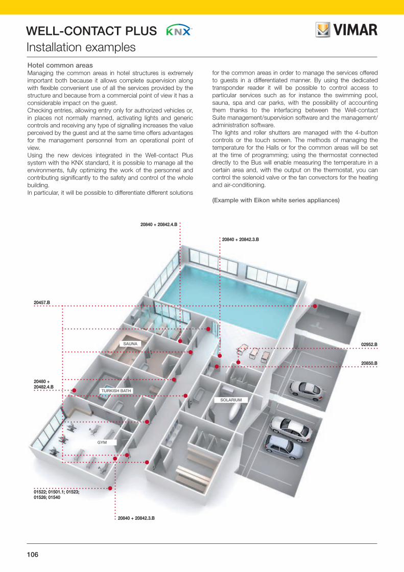
106
WELL-CONTACT PLUSInstallation examples
for the common areas in order to manage the services offered to guests in a differentiated manner. By using the dedicated transponder reader it will be possible to control access to particular services such as for instance the swimming pool, sauna, spa and car parks, with the possibility of accounting them thanks to the interfacing between the Well-contact Suite management/supervision software and the management/administration software. The lights and roller shutters are managed with the 4-button controls or the touch screen. The methods of managing the temperature for the Halls or for the common areas will be set at the time of programming; using the thermostat connected directly to the Bus will enable measuring the temperature in a certain area and, with the output on the thermostat, you can control the solenoid valve or the fan convectors for the heating and air-conditioning.
(Example with Eikon white series appliances)
Hotel common areas Managing the common areas in hotel structures is extremely important both because it allows complete supervision along with flexible convenient use of all the services provided by the structure and because from a commercial point of view it has a considerable impact on the guest. Checking entries, allowing entry only for authorized vehicles or, in places not normally manned, activating lights and generic controls and receiving any type of signalling increases the value perceived by the guest and at the same time offers advantages for the management personnel from an operational point of view.Using the new devices integrated in the Well-contact Plus system with the KNX standard, it is possible to manage all the environments, fully optimizing the work of the personnel and contributing significantly to the safety and control of the whole building.In particular, it will be possible to differentiate different solutions
SOLARIUM
TURKISH BATH
SAUNA
GYM
20457.B
20480 + 20482.4.B
01522; 01501.1; 01523; 01526; 01540
20840 + 20842.3.B
20850.B
02952.B
20840 + 20842.3.B
20840 + 20842.4.B

107
WELL-CONTACT PLUS
WE
LL-C
ON
TAC
T P
LUS
WE
LL-C
ON
TAC
T P
LUS
EX
AM
PLE
S
Installation examplesConnection diagram
NotesIn the diagram only some of the inputs and outputs equipping the devices are used.
To avoid electrical interference in the power supply circuit caused by the electric locks, it is advisable to power them with a dedicated transformer.
IMPORTANT:The transponder readers and the vertical pocket ones should be powered separately from all other loads (electric locks, lamps, con-tactors, etc.) using a transformer dedicated to them art. 16887 whose outputs should be used solely for these two devices.
*
20840 + 20842.3.B
20840 + 20842.3.B
20850.B 20850.B 20840 + 20842.4.B
0154001501.1
Reception
20450.B
12 - 24 V~
SV
230 V~
02952.B
Light n*
Electric lock
20457.B
230 V~
L1
NL2
Massage light
Turkish bath light
01526 01524 01522
M M
Swimming Pool roller shutter
Toilet light
Garage light
Gym roller shutter
230 V~
* Swimming pool, Sauna, Solarium, Turkish bath, Gym, Garage, Massage parlour, Changing room
KNX Bus
KNX Bus
KNX Bus
*

108
WELL-CONTACT PLUSInstallation examples
the meeting room enables controlling the lights, roller shutters, temperature and scenarios of the entire system. The lights and roller shutters in the reception and in the technical room are instead managed by the 4 independent pushbutton controls combined with the respective buttons identifying the controlled service; the infrared sensors installed in the bathroom switch the lighting on for a set time only when they detect the presence of one or more people in order to optimize energy consumption Finally, all the accesses made (employee, time, etc.) and any alarms or faults will be monitored and saved by the PC in the reception via the Well-contact Office Suite software.
(Example with Plana series appliances)
Offices The example in the figure illustrates the use of the Well-contact Plus devices with the KNX standard in the typically tertiary sector in which there is the need to manage diversified accesses to the various offices/rooms while monitoring it all from the PC in the reception; the control of the lights and roller shutters is performed using the 4-button controls and the touch screens. By means of the transponder reader, entry to the offices and technical room will be allowed only for cleared users; the personnel manager will have access to all the areas 24 hours a day every day of the week while employees can only enter their own office and only on business days. The 3-module recess-mounting touch screens enable managing the lights, roller shutters and any scenarios for the office in which they are installed; the colour touch screen installed in
14450
14480 + 14841.0 + 14841.1+ (2) 14841.3
01501.1; 01523; (3) 01524
14840 + 14842.0 + 14842.1
14848
14849
(4) 14850(3) 14457
14840+ 14841.0+ 14841.1
+ (2) 14841.3
14849
02952.B
01540

109
WELL-CONTACT PLUS
WE
LL-C
ON
TAC
T P
LUS
WE
LL-C
ON
TAC
T P
LUS
EX
AM
PLE
S
Installation examplesConnection diagram
NotesIn the diagram only some of the inputs and outputs equipping the devices are used.
To avoid electrical interference in the power supply circuit caused by the electric locks, it is advisable to power them with a dedicated transformer.
IMPORTANT:The transponder readers and the vertical pocket ones should be powered separately from all other loads (electric locks, lamps, con-tactors, etc.) using a transformer dedicated to them art. 16887 whose outputs should be used solely for these two devices.
14840 + 14841.0+ 14841.1+ (2) 14841.3
14840 + 14841.0+ 14841.1+ (2) 14841.3
14850 14850 14849 14849
14848.1
14840 + 14842.0+ 14842.1
0154001501.1
Reception
20450.B
12 - 24 V~
SV
230 V~
02952.B
Light n*
Electric lock
14457
230 V~
L
N
01524 01524 01524
M M MM M M
Recep-tion roller shutter
Shutter 1Meeting room
Roller shutterTech. room
V+ V-
30 V
01523
Light 1Bath-room Recep-
tion room light
Light 2Bathroom
Roller shutterOffice 1
Roller shutterMeeting room
Roller shutterOffice 2
230 V~
* Corridor, Office 1, Meeting room, Technical room, Office 2
KNX Bus
KNX Bus
KNX Bus
*
*

110
WELL-CONTACT PLUS
management and the video door entry phone answering service. It also allows viewing of IP and analogue cameras on 2 wires, enabling Elvox DVR control (live viewing, recording, PTZ movement) and, if enabled for web browsing, it supports multimedia functions (web radio, weather forecasts, news, RSS feeds) .
(Example with Eikon Evo series appliances)
Automation systems, video door entry and web serverThe diagram shows a system in which the automation and video door entry systems as well as being integrated, can also be controlled either locally or from a distance via web server. The 10" IP multimedia video touch screen monitors and controls all the automation and video door entry functions, such as viewing and voice communication with the caller, electric lock opening, switching on stair lighting and other auxiliary functions, intercom calls, ringtone customization, missed call
Installation examples
01545, 6922, 69MX, 69AM, 6582, 01501.1, 01524, 01830, 01523
20565, 20570, 20840
21848, 20840
20557, 20008.0+20031
20840
02952, 20840
1222+13F5
Router
21553.120840
20840
•

111
WELL-CONTACT PLUS
WE
LL-C
ON
TAC
T P
LUS
WE
LL-C
ON
TAC
T P
LUS
EX
AM
PLE
S
Installation examplesConnection diagram
2
2
2
2
2057020565
01523 01524
HVAC Light 1 Light 2
SVM M
01501.1
Electric lock
2
2
2
2
2
COAX
2057721553.1
02952
21848
Bus 2+ -
01545
01830
LAN
LAN
NL
230 V~
Bus 1/0
2084020840208402084020840
Bus 1/0
UTP/FTP
AUX
Router1222+13F5
69AM 65826922 69MX
01524
M M

112
DISPLAY MODULE.
Installed in each room, it manages patient calls, displays the number of the ward and of the room.
The system for secure communica-tions and integrated management.Whether it is a small or large hospital, private clinic or nursing home the Call-way system is the ideal solution to manage emergencies swiftly and efficiently. Developed to be in compliance with VDE0834-1-2, the call system integrates seamlessly into any structure. The Call-way range also now features Plana series devices, controls, socket outlets and cover plates: the whole range has been subjected to a silver ion (Antibacterial) treatment to reduce the growth of bacteria and ensure the greatest hygiene.

113
ANTIBACTERIAL DEVICES.
Antibacterial cover plates and devices treated with silver ions to reduce the replication of germs and bacteria. This technology is effective on more than 50 different species of bacteria, able to reduce proliferation by more than 90% over a period of 24 hours.
ANTI-STRANGULATION MINI KEYPAD.
Installed in each room, it allows patient calls and 2 light controls. In antibacterial treatment, it also offers a quick-release anti-strangulation feature.
CORRIDOR DISPLAY.
Installed in the various wards it displays system events such as calls, attendance, faults, alarms and messages for the ward (including advertisements).

CALL-WAY
114
Catalogue section

CALL-WAY
115
CA
LL-W
AY
SELECTION GUIDE from page 116
GENERAL CHARACTERISTICS from page 120
SYSTEM DEVICES from page 132
FIRST GENERATION CALL-WAY APPLIANCES from page 154
ANTIBACTERIAL PLANA DEVICES from page 156
INSTALLATION EXAMPLES from page 176

CALL-WAY
116
Selection guideDescription CodeCommunication modules
Communication terminaland call display with display voice unit, 24 Vdc power supply (SELV), antibacterial treatment, equipped with flat cable for connecting the two units, complete with double base for semi-flushed installation on hollow walls, on boxes with 60 mm centre distance or on 3-module boxes
Display modulefor viewing calls, 4 buttons for scrolling, call, priority call and cancelling, 24 Vdc power supply (SELV), antibacterial treatment, complete with single base for semi-flushed installation on hollow walls, on boxes with 60 mm distance between centre or 3-module boxes
Voice unit modulewith 4 buttons for activating and controlling music and activating voice communication, antibacterial treatment, equipped with flat cable for connection to the display unit, complete with single base for surface installation
Accessories
Removable spare terminal with 6+2 screw pins for display module
Display and accessories
Corridor displayto view the events of the Call-way system
Wall fixing bracketfor corridor display
Ethernet/RS485 interfaceinstallation on DIN rail (60715 TH35), occupies 9 modules size 17,5 mm
Mini keypad
Mini keypadwith 2 light controls, antibacterial treatment, anti-strangulation function
02085
02089.AB
02080.ABwhite
02081.ABwhite
02082.ABwhite
02097
02098
02079

CALL-WAY
117
CA
LL-W
AY
Selection guideDescription CodeFlush mounting appliances
Call button with red reassurance light, antibacterial treatment - 2 modules
Cord-operated call button with red reassurance light, antibacterial treatment - 2 modules
Cancel button with acoustic signal for receiving other calls and green indicator light, antibacterial treatment - 2 modules
Landing lamp
Landing LED lamp four colours (green, white, red, amber), for surface mounting
DIN rail appliances (60715 TH35)
Line coupler with Ethernet and voice control, 24 Vdc power supply, installation on DIN rail (60715 TH35), occupies 9 modules of 17,5 mm
Telephone coupler 24 Vdc power supply, installation on DIN rail (60715 TH35), occupies 9 modules size 17.5 mm
ESPA 4.4.4 interface for connection without PC between Call-way and a DECT/pager system or equipped with ESPA 4.4.4 interface, installation on DIN rail (60715 TH35), occupies 9 modules size 17,5 mm
Programmable card 8 inputs 8 outputs for managing multiple rooms, installation on DIN rail (60715 TH35), occupies 8 modules size 17,5 mm
Devices and accessories
Power supply unit with 24 Vdc output (SELV) 6,5 A, power supply 115/230 V~ 50/60 Hz
CableCat. 5e, shielded, 4-pair, 24 AWG with LSZH sheath, grey - 305 m
02084
02094
02078
02095
02096
02090
03061
14501.ABwhite
14504.ABwhite
14503.ABwhite

CALL-WAY
118
Description CodePlana control devices with antibacterial treatment
Blank module
1-way switch1P and 2P, 16 AX 250 V~, lightable, replaceable button
Reversing switch1P 16 AX 250 V~, lightable, replaceable button
2-way switch1P 16 AX 250 V~, lightable, replaceable button
Push button1P NO 10 A 250 V~, lightable, replaceable button
Interchangeable button2 modules, loop lightable
Cord-operated push button1P NO 10 A 250 V~, with 1,5 m cord and knob
Plana dimmer with antibacterial treatment
Universal dimmer230 V~ 50 Hz, with built-in rotary potentiometer, minimum brightness setting, visible in darkness
Plana socket outlets with antibacterial treatment
Bpresa SICURY2P+E 16 A, Italian standard type P17/11,
Universal SICURY2P+E 16 A, for Europlugs 2P 2.5 A, 2P and 2P+E 10 A and 16 A Italian standard plugs, 2P+E 16 A German standard plugs - 2 modules
German standard SICURY 2P+E 16 A 250 V~- 2 modules
French standard SICURY 2P+E 16 A 250 V~ - 2 modules
Plana socket outlets for dedicated power supply lines with antibacterial treatment
Bpresa SICURY2P+E 16 A, Italian standard type P17/11, red
Universal SICURY2P+E 16 A, for Europlugs 2P 2.5 A, 2P and 2P+E 10 A and 16 A Italian standard plugs, 2P+E 16 A German standard plugs - 2 modules
Selection guide
14041.AB
14013.AB
14005.AB
14008.AB
14136.AB
14203.AB
14210.AB
14208.AB
14212.AB
14203.AB.Rred
14210.AB.Aorange
14210.AB.Rred
14210.AB.Vgreen
14022.AB
14052.AB
14001.AB 14015.AB

CALL-WAY
119
CA
LL-W
AY
Description CodePlana shaver supply unit with antibacterial treatment
Shaver supply unitwith 20 VA isolating transformer, supply voltage 230 V~ 50/60 Hz, 120 V~ output voltage for 2P 15 A 125 V~ American standard plugs with non-polarized flat blades, and 230 V~ output voltage for 2P 2,5 A Europlugs - 3 modules
Plana special socket outlet made of antibacterial treatment
Socket outlet2P 6 A 24 V (SELV), for plugs ø 3 mm with 12,4 mm distance between centre
Plana signal sockets with antibacterial treatment
RJ11 socket6 positions, 4 contacts (6/4), screw terminals
RJ45 socketwith Netsafe connector Cat. 6, unshielded, T568A/B universal wiring, 8 contacts, insu-lation-piercing terminals without using tools
RJ45 socketwith Netsafe connector Cat. 6, shielded, T568A/B universal wiring, 8 contacts, insu-lation-piercing terminals without using tools
RJ45 socket8 positions, 8 contacts (8/8), screw terminals
Coaxial socket outlet TV-RD-SAT 5-2400 MHz direct (shunted), with male connector, connection attenuation 1 dB. Allows the passage of direct current and control signals (24 V 500 mA max)
Plana cover plates with antibacterial treatment
2-module
3-module
4-module
7-module
4-module (2+2)71 mm distance between centre
6-module (2+2+2)71 mm distance between centre
8-module (2+2+2+2)71 mm distance between centre
Selection guide
14290.AB
14330.AB
14320.AB
14339.AB.13
14339.AB.14
14342.AB
14300.AB.01
14642.AB.01
14657.AB.0114657.AB.01
14643.AB.01
14644.AB.01
14669.AB.01
14654.AB.01
14653.AB.01

CALL-WAY
120
General characteristics
the display (modules and terminals) in order to supervise the entire system, save events (calls, room number, etc.), manage call priority and voice communication between rooms, between wards and to external devices (fixed or cordless phones, pagers, etc.), diagnostic call management (via clean contact from medical equipment to the display modules or communications terminals).
The display modules, combined with devices called voice modules, will constitute the communication terminals; in addition to displaying the type and characteristics of the calls, the terminal will then not only enable hands-free two-way communication with another terminal but also transmission of a music channel connected to an external source and, if there is a telephone coupler, also interfacing with pagers, switchboards, etc., in order to broadcast announcements and/or talk using the regular phone.
A call by a patient can be made with a special "mini keypad" or a ceiling pull; for this purpose the Call-way system range includes three buttons with an indicator light that match the Plana series and enable having a suitable user interface that is ergonomic, non-invasive on the wall and above all coordinated with all the other components of the traditional electrical system.
The functions/services that the Call-way system is able to offer can be subdivided as follows:
Services for patientsEach patient will be able to make a distress call with a simple manual operation on the mini keypad that is connected to the call button on the bed head.On activating the call, with either the mini keypad or the button, the caller bed red light will come on (brighter than when on stand-by) which will give the patient the perception and the reassurance of the call being made.
If the room terminal has a voice module, the patient will be able to communicate with nurses and/or physicians via the room terminal (after the medical personnel have started the communication).
The terminal can also be used to receive and adjust the volume of an external sound source (music channel or otherwise); in the case of a service call, an internal relay will automatically switch over the device which will give priority to this call.
From the room's bathroom it will also be possible, as mentioned above, to make a distress call with the dedicated pull-cord; this button also has a red reassurance light that will come on (brighter than when on stand-by) simultaneously with the call for help.
Field of applicationThe new Call-way system complies with the standard VDE0834-1-2 and, within the framework of existing receptive structures, it enables creating management and supervision systems for calls and communications by patients and/or medical and paramedical staff to the switchboard, other rooms or wards, and outside the hospital. In recent years, the emerging concept of the high-tech hospital and the proliferation of nursing homes and care facilities for the elderly and/or physically challenged has led the market to develop solutions that guarantee increasingly high standards of service and organisation to meet all types of requirement.
The result is Call-way which, in addition to considerably improving organisation in hospitals, private clinics and care facilities, also increases the level of service and safety for patients and optimises the efficiency and effectiveness of the health care professionals working there.
The devices in the Call-way system, developed on Bus technology, offer solutions that enable the highest level of efficiency, responding perfectly to all installation requirements and the constraints imposed by the different facilities such as hospitals, clinics, nursing homes and care facilities in general. The system is available in English too.
Technical specificationsWhat distinguishes the Call-way system is its ease of installation and programming, along with the clarity and flexibility of its use; these devices enable two distinct operating modes:• VDE-0834 with PC/Display for Corridor The system is operated by the ADL-EF and is compliant
with the VDE0834 -1-2 standard on signalling systems in healthcare facilities. The PC/DC is configured for managing: logs, statistics, ward consolidations and voice calls via the Phone coupler (AT).
• VDE-0834 without PC The system is still managed by the ADL-EF and is compliant
with VDE0834 -1-2. Interfacing is guaranteed with DECT/pager systems and voice calls to the wards but accessory functions are not handled such as logs, statistics and ward consolidations.
Methods that invalidate VDE0834-1-2• Off-Line Method to ensure a minimum level of service in the event
of failure of an ADL-EF in the network. In the event of failure the secondary backbone will continue to operate and the supervision and corridor display will signal the malfunctioning with dedicated signals.
• On-line This is equivalent to the old way where there is a personal
computer that centralizes all the information shown on

CALL-WAY
121
CA
LL-W
AY
General characteristics
The half-duplex communication can take place in two ways:- Hands-free, where the “direction” of the communication is
established by the tone of voice; the exchange is made when the voice unit module recognizes a higher sound level of one speaker than the other.
- Push to talk, where the communication exchange between the parties is made by pressing the "voice direction command" button of the voice module (push-to-talk, release to listen)
Dedicated services for the hospital management/organizationThe Call-way system will enable optimizing human resources, significantly improving the efficiency of the service in the ward.
Each display in the room will be able to instantly show the status of calls, the place of origin and the presence of medical and nursing staff; when the installed device is a communica-tion terminal it will be possible to answer and deal with patient calls at a distance, broadcast room and ward announcements and interface with fixed telephone devices, pagers or cordless phones.
With the aid of a PC, with Call-way installed, it will be possible to save the status of events (calls, presences, processing times of calls, etc.) directly to the file so that it can then be stored and subsequently used in case of need.
Services for medical and paramedical staff Using the Call-way system will enable medical and nursing personnel to respond to calls promptly even from a distance (version with voice communication) improving and optimizing response times considerably. Via the display you can view all the current events (calls, guests in room, priority levels, places of origin of the calls, system failures) and cancel calls locally once the patient has received the care they requested.
If there is a communication terminal, it will be possible to respond locally to a patient call from any room equipped with a terminal and cancel the call at a distance; if the staff providing care to the patient finds a situation of danger or severity they can make an emergency call to request immediate medical attention.
The voice unit channel is always activated with system control when there is a call to the room (generated by the telephone coupler) or a voice unit conference request.
The manner in which the communication is handled (full-duplex/half-duplex) is determined by the device that initiates the voice unit conference:- telephone coupler: always full-duplex- voice: depending on the chosen configuration
VIMARVIMAR
VIMARVIMAR
VIMARVIMAR
VIMARVIMAR
VIMARVIMAR
Services for patientsThe patient makes a call with the mini keypad or cord-operated push button; the communication terminal is activated in the
nurses' room and in the room; the red light (from the mini key-pad) or white light (from the ceiling pull) turns on in the corridor.

CALL-WAY
122
General characteristics
VIMARVIMAR
VIMARVIMAR
VIMARVIMAR
VIMARVIMAR
VIMARVIMAR
VIMARVIMAR
VIMARVIMAR
VIMARVIMAR
VIMARVIMAR
VIMARVIMAR
Services for medical and paramedical staffThe nurse comes to the room, cancels the call and shows she needs to remain via the communication terminal; the call is
deactivated in the nurses' room; the red or white light turns off in the corridor and lights up green.
Dedicated services for the hospital management/organizationThe acceptance department and the medical staff within the
facility can monitor calls, operations and personnel in order to maximize resources.

CALL-WAY
123
CA
LL-W
AY
General characteristicsSystem architectureThe Call-way system uses a Bus as a means of transmission, composed of cables with the following characteristics:• 2x2.5 mm2 for connecting the 24 Vdc power supply• 2x0.22 mm2 FTP Cat. 5e shielded for data transmission• 2x0.22 mm2 FTP Cat. 5e shielded for voice transmission• 2x0.22 mm2 FTP Cat. 5e shielded for transmitting announce-
ments/music channel.As an alternative to the three FTP cables, a single SSTP cable can be used.Using the Bus to connect devices ensures not only a simplifica-tion of the installation, wiring and maintenance operations, but also a high level of immunity from interference. The main feature of the system architecture is its open loop structure; this allows each device connected to the line to com-municate with all the other components in two distinct modes:• VDE-0834 with PC/Display for Corridor The system is operated by the ADL-EF and is compliant with
the VDE0834 -1-2 standard on signalling systems in health-care facilities. The PC/DC is configured for managing: logs, statistics, ward consolidations and voice calls via the Phone coupler (AT).
• VDE-0834 without PC The system is still managed by the ADL-EF and is compliant
with VDE0834 -1-2. Interfacing is guaranteed with DECT/pager systems and voice calls to the wards but accessory functions are not handled such as logs, statistics and ward consolidations.
The basic element on which the system architecture stands is the line; this is also the starting point for expanding the system up to the maximum possible configuration in terms of devices and shared functions. Each line can be composed of at most 128 devices, each one with its own physical address (communication terminals,
display modules, telephone coupler) and the number of power supply units needed will be determined according to the num-ber of components; each power supply unit delivers an output current of 6.5 A.The system is able to manage up to 128 lines connected together by line couplers; all the connected devices commu-nicate with each other over an Ethernet network, exchanging information over the network in accordance with the rules of the communication protocol.
The range of devices comprising the Call-way system is greatly reduced thanks to the considerable flexibility and functional-ity they offer; just by using the room device (communication terminal or display module), you can control and manage all the inputs/outputs in the room; the default configuration is as follows:• 3 bed call buttons• 1 ceiling pull • 1 ceiling pull cancellation• 4 landing indicator lamps (call, nurse present, bathroom call
and assistance call or diagnostics).
The communication terminal and the display module also allow the following configurations:• 3 bed calls, 1 bathroom call and 1 bathroom call cancellation• 2 bed calls, 2 diagnostics calls and 1 bathroom call• 2 bed calls, 2 diagnostics calls and 1 bathroom call cancellation• 4 bed calls and 1 bathroom call• 5 bed calls
The devices are connected serially since, should one of the components malfunction, the proper operation of the other devices is not affected and the services in the other rooms are not impaired.
Call-way system general outline
A
A A A A A
Dorsale secondaria
2 x 2,5 mm2 (alimentazione)
Legenda:
I cavi B e C possono essereriuniti in un unico cavo SSTP (Cat.6 4 Coppie intrecciate schermate singolarmente)
B 1 coppia FTP - Cat. 5e (dati)
C 2 coppie FTP - Cat. 5e (fonia/musica)Locale caposala Soggiorno Bagno assistito
Degenza DegenzaDegenza Degenza
BBC
BC
BC
BC
BC
BC
BC
JP
I
ISP
RUN DORSALE PRINCIPALE
DORSALE SECONDARIAM2 M1 F2 F1 D2 D1 – – –+ + +
ALIM. AUXINDIRIZZO
RUN
DL1 DL2 DL3
PRI SEC
PRI SECD2 D2 – +
PROGDORSALEPRINC.
ON
1 2 3 4 5 6 7 8
DIP ALIM.
492.20920 0A 0507 VIMAR - Marostica - Italy
AUX
02092
ACCOPPIATORE DI LINEA
230 Vac
02094
02090
C
PC o
02097
JP
I
ISP
RUN DORSALE PRINCIPALE
DORSALE SECONDARIAM2 M1 F2 F1 D2 D1 – – –+ + +
ALIM. AUXINDIRIZZO
RUN
DL1 DL2 DL3
PRI SEC
PRI SECD2 D2 – +
PROGDORSALEPRINC.
ON
1 2 3 4 5 6 7 8
DIP ALIM.
492.20920 0A 0507 VIMAR - Marostica - Italy
AUX
02092
ACCOPPIATORE DI LINEA
230 Vac
02094
02090
JP
I
ISP
RUN DORSALE PRINCIPALE
DORSALE SECONDARIAM2 M1 F2 F1 D2 D1 – – –+ + +
ALIM. AUXINDIRIZZO
RUN
DL1 DL2 DL3
PRI SEC
PRI SECD2 D2 – +
PROGDORSALEPRINC.
ON
1 2 3 4 5 6 7 8
DIP ALIM.
492.20920 0A 0507 VIMAR - Marostica - Italy
AUX
02092
ACCOPPIATORE DI LINEA
230 Vac
02094
02090
PC o
02097
PC o
02097
Display di corridoio
Switch Ethernet
Dorsale secondariaDorsale secondaria
Display di corridoio Display di corridoio
PCor
02097
Corridor display
Switch Ethernet
Corridor display Corridor display
PCor
02097
PCor
02097
Secondary backbone Secondary backbone
2 x 2,5 mm2 (power)
Legend
1 couple FTP - Cat. 5e (data)
B and C cables can be joined to SSTP cable (4-pair twisted, shielded, cat. 6)
2 couples FTP - Cat. 5e (voice/music)
Secondary backbone
Bed rest Bed rest Bed rest Bed rest
Staff supervisor room Living room Supervised bath

CALL-WAY
124
General characteristics
Call-way system wiring diagram
5
0209002094
230 V~
02080.AB
02080.AB
02084
02084
14342.AB
14342.AB
14342.AB
14501.AB
14501.AB
14501.AB
14503.AB
14503.AB
14504.AB
14504.AB
4
4
4
3
3
3
3
3
4
4
5
02089.AB
02089.AB
02089.AB
2
2
4
1 cp
FT
P
2 cp
FT
P
2x2.
5 m
m2
2
4
1 cp
FT
P
2 cp
FT
P
2x2.
5 m
m2
2
2
4
1 cp
FT
P
2 cp
FT
P
2x2.
5 m
m2
LEGEND:02080.AB - Communication terminal02089.AB - Mini keypad02090 - Power supply unit02094 - Line coupler14342.AB - RJ45 socket14501.AB - Call button14503.AB - Pull-cord call button14504.AB - Cancellation button
2
2

CALL-WAY
125
CA
LL-W
AY
General characteristicsSecondary backbone connections
Main backbone connections
D1
–
+
D2
F2M1
F1
M2
D1
–
+
D2
F2M1
F1
M2
D1
–
+
D2
––
++
D1
–
+
D2
F2M1
F1
M2
D1
–
+
D2
F2M1
F1
M2
D1
–
+
D2
F2M1
F1
M2
1cpFTPCAT5
2 x 2,5 mm2
Dorsaleprincipale
2cpFTPCAT5
1cpFTPCAT5
2cpFTPCAT5
Schermatura
Schermatura
Schermatura
Schermatura Schermatura
L
L230 V~
N
N –V –V +V +V
0209402080.AB
o02081.AB
02080.ABo
02081.AB
02080.ABo
02081.AB
02080.ABo
02081.AB
02090
XB
RJ45
Utilizzare un cavo crossato in assenza di switch
Display di corridoio
02078
+–
XB
XL
XV
XM
XH
Ingresso annuncivocali da PC
Canale annunci /diffusione musicale
Telefono locale(VOX)
PABX
D1D2
F2M1
F1
M2
BABA
GNDIN
GNDIN
Corridor display
Use a twisted cable when switch default
Main backbone
Shield
Shield oror orShield
Shield
Local phone(VOX)
PC voiceanoucemens
input
Anoucemens channel /music diffusion
Shield
D1
2
2
2
2
1
1
UTP 4 coppie
230 VacL N
L N
L N
UTP 4 coppie02090
02090
02090
UTP 4 coppie
D2F1F2M1M2
++–
230 Vac
+–
+
230 Vac
–
–
02094 - 1
Switch ethernet
Display di corridoio
– – –+ + +
02094ADL - EF COUPLER
Call-Way
Cavi di alimentazione 2x2,5 mm2
Schermatura
Schermatura
SSTP 4 coppie
D1
1
D2F1F2M1M2
+–
02094 - 2
D1
1
D2F1F2M1M2
+–
02094 - 3
D1D2
F2M1
F1
M2
–
+
02080.ABo
02081.AB
02080.AB
D1D2
F2M1
F1
M2
–
+
02081.AB
D1D2
F2M1
F1
M2
–
+
02080.AB
D1D2
F2M1
F1
M2
–
+
02081.AB
D1D2
F2M1
F1
M2
–
+
Power cables 2x2,5 mm2
UTP 4 couples
UTP 4 couples
UTP 4 couples
Shield
Shield
SSTP 4 couples
Switch ethernet
Corridor display

CALL-WAY
126
General characteristics
Display wiring diagram, with no voice unit
Reach the module with cables size 1 - 1.5 mm2
Earthing must not be interrupted by the cable that reaches the one that goes to the next module
At the end of the line, earth must be left open
Earth must be con-nected to GND (-) directly on the power supply unit
24 V power supply back-bone: the backbone must have a cable cross section of at least 2.5 mm2
Wiring diagram for display, with cables for voice and music
Earth must be connected to GND (-) directly on the power supply unit
24 V power supply backbone: the backbone must have a cable cross section of at least 2.5 mm2
At the end of the line, earth must be left open
Reach the module with cables size 1 - 1.5 mm2
Earthing must not be interrupted by the cable that reaches the one that goes to the next module
The data cable earths must NOT be in com-mon with those of the voice cable, they must be suitably insulated in order to avoid interfer-ence from other non-insulated cables
Example of IN/OUT connection
02081.AB 02081.AB
Room 1 Room 2
Room 1 Room 2
02081.AB 02081.AB
Example of IN/OUT wiring
The DATA and VOICE cable shields must never be connected together along the path of the cable, but only at the start of the system. The junction point at the start must be connected to the nearest negative (V- of the power supply unit 02090).
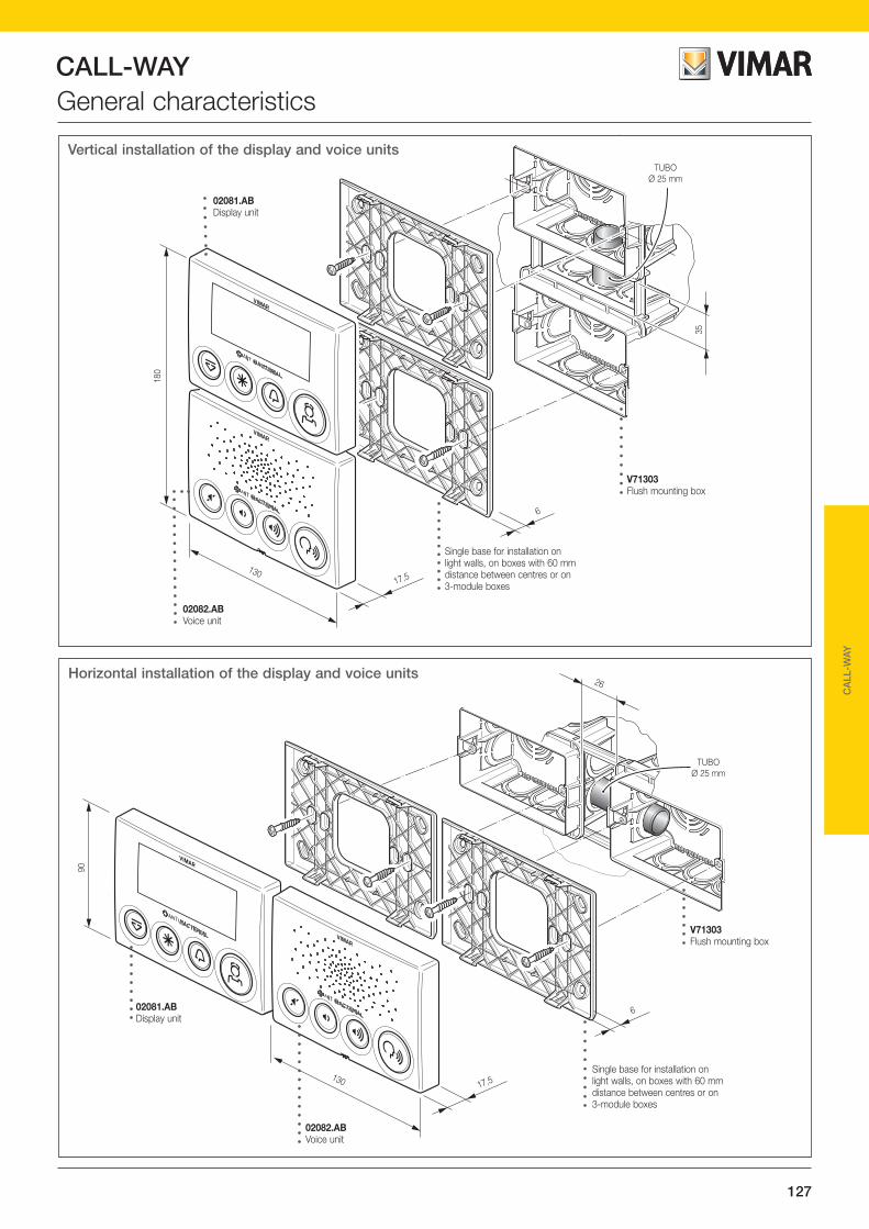
CALL-WAY
127
CA
LL-W
AY
General characteristics
6
90
130 17,5
26
TUBOØ 25 mm
Horizontal installation of the display and voice units
02081.ABDisplay unit
02082.ABVoice unit
Single base for installation on light walls, on boxes with 60 mm distance between centres or on 3-module boxes
V71303Flush mounting box
6
13017,5
180
35
TUBOØ 25 mm
Vertical installation of the display and voice units
02081.ABDisplay unit
02082.ABVoice unit
Single base for installation on light walls, on boxes with 60 mm distance between centres or on 3-module boxes
V71303Flush mounting box

CALL-WAY
128
General characteristicsInstallation componentsWhen creating an installation with the Call-way system, the following components are used: • Power supply unit• Line coupler• Communication terminal• Display module• Voice unit module• Telephone coupler• Call buttons, mini keypad and landing lamps
Set the systemIt is important, in the phase of system setting, to have a clear idea of which functions are to be implemented according to the type of assistance required; this will obviously depend on the type of the facility where the system is to be installed since, for example, a hospital will have different needs to those of a centre for the physically challenged.
Call-way system devices can be configured, depending on the different needs, in different ways; the types of configuration are the following: • self-learning, via extremely simple operations carried out
manually on the buttons of the display module, in the case of VDE-0834 mode without PC
• using PC software in the case of VDE-0834 mode with PC/Corridor Display.
As regards the actual preparation of the system and therefore laying out the cables and positioning the devices, it will be enough to take into account the following precautions:• Add up the power inputs of the single devices (that must be
no more than 128 per line) such as display modules, com-munication terminals, line coupler and telephone coupler so as to determine the number of power supplies to install (if the current absorption of the devices in a line is greater than 6.5 A it is necessary to have a second power supply and so on).
When calculating the current absorption it is necessary to take into account the consumption of the button LEDs (bed call, ceil-ing pull), the mini keypad LEDs and the lamps connected to the display modules and to the communication terminals; each LED has a consumption of 30 mA while for the lamps each module will be able to deliver up to 250 mA.
In the case of wards with a large number of rooms (from 20 to 30 rooms), the total consumption of the lamps and LEDs, which must be added to that of the system devices, is given by the sum of the current absorption of the lamps and LEDs multiplied by 0.2 (coefficient taking into account the fact that it is never possible for all the lamps and LEDs in a system to switch on simultaneously). Example In a ward of 20 rooms, each room is equipped with a communi-cation terminal which is connected to a bed call button and two RJ45 sockets with their mini keypads, a ceiling pull, a call reset button and a landing indicator lamp. The current absorption of the room devices will be equal to:- Communication terminal current absorption 70 mA;- Landing lamp output current absorption max 250 mA;- Push buttons LED current absorption 1 x 30 mA (30 mA). - Mini keypads LED current absorption 2x 30 mA (60 mA)
The total consumption of the devices in the ward (20 rooms), equal to 2760 mA (2.76 A), is given by:- (250 mA + 30 mA + 60 mA) x 20 x 0.2 + 20 x 70 mA. The power supply 02090, which delivers an output current of 6.5 A, is thus easily sufficient to provide power to the entire ward.• Evaluate accurately, according to the size of the healthcare
facility, whether a line can be considered as a floor or whether a line can cover a number of floors or, vice versa, whether the property is so large that covering a floor requires a number of lines (therefore, at the design stage, take account of the characteristics of a line in terms of number of devices and consumption).
• The number of lines forming the system will determine the number of couplers that must be installed (the lines are con-nected together by line couplers that allow communication between devices belonging to different lines).
• Determine the desired requirements for the voice/announce-ments functions in order to establish the number and location of the phone couplers intended for managing voice commu-nications, interfacing with PABX switchboards and transmit-ting the announcements/music channel.
If, for example, a single voice channel is believed sufficient for the entire system, it will be enough to have the telephone coupler on one line; conversely, if you want to implement simultaneous and independent communication between the terminals of a ward and all the others you will need a tel-ephone coupler for each ward.
• The Call-way software lets you easily manage operating profiles/scenarios by time slots or specific days (holidays, etc.) so as to enable centralizing the control desks and all the signalling and voice functions associated with them; this is in order to optimize the presence of personnel without reducing the quality of the service and the level of safety.
• Cables need to be laid depending on the type chosen for system operation (signalling only with display module or sig-nalling and voice with communication terminal).
Call-way system devices, apart from those with DIN pins, can be installed in a V71303 flush mounting 3 module box or in a round 60 mm diameter box. Although display module 02081.AB and communication terminal 02080.AB are wall mounted devices, they need a flush mounting 3 module box or ø 60 mm round box to house the terminals.
Summary of features and functionsThe Call-way system is designed to meet the diverse applica-tion requirements of public and private health institutions for providing care; as mentioned earlier, it is easy to see how the demands of a nursing home can, for example, be different from those of a hospital or private clinic. Being able to meet those demands and trying to ensure opera-tional independence, typical of distributed intelligence systems, are the conditions with which the Call-way system has been implemented.Each ward can be equipped with one or more operating sta-tions (control desks) that directly manage their peripheral units; within the operating station or ward, solutions can be implemented with only the display or with the communication terminal.
Whether to use a personal computer or not uniquely definesthe type of operation;

CALL-WAY
129
CA
LL-W
AY
General characteristicsPeripheral wiring diagram
• VDE-0834 with PC/Display for Corridor The system is operated by the ADL-EF and is compliant with
the VDE0834 -1-2 standard on signalling systems in health-care facilities. The PC/DC is configured for managing: logs, statistics, ward consolidations and voice calls via the phone coupler (AT).
• VDE-0834 without PC The system is still managed by the ADL-EF and is compliant
with VDE0834 -1-2. Interfacing is guaranteed with DECT/pager systems and voice calls to the wards but accessory functions are not handled such as logs, statistics and ward consolidations.
Methods that invalidate VDE0834-1-2• Off-Line Method to ensure a minimum level of service in the event of
failure of an ADL-EF in the network. In the event of failure the secondary backbone will continue to operate and the supervi-sion and corridor display will signal the malfunctioning with dedicated signals.
• On-line This is equivalent to the old way where there is a personal
computer that centralizes all the information shown on the display (modules and terminals) in order to supervise the entire system, save events (calls, room number, etc.), manage call priority and voice communication between rooms, between wards and to external devices (fixed or cordless phones, pag-ers, etc.), diagnostic call management (via clean contact from medical equipment to the display modules or communications terminals).
In the case of on-line operation it becomes necessary to use a line coupler upstream of the backbone (main line from which are derived all the other lines). Note that, in any case, passing from one system mode to the other does not require replacing any existing components, but only integrating them with additional devices. Using Bus technology is particularly advantageous especially in economic terms; due to the ease of installation and a significant reduction in the number of conductors, it is possible to dramati-cally reduce wiring and system configuration times
Equally important is the time for system maintenance; in the event of malfunctioning, internal self-diagnosis recognizes the nature of the fault, identifying the affected device that can be replaced very practically and fast while avoiding unwanted sys-tem shutdowns and prolonged disruptions in the room.
Interoperability with external systemsThe Call-way system can easily communicate with paging sys-tems (via the ESPA 4.4.4 protocol) and telephone equipment or PABX switchboards.This type of application enables call transmission even in places where normally there are no specific terminals (for communica-tion or display modules) and allows the medical and paramedi-cal staff to be reached by messages or calls from patient rooms. If fixed telephone equipment or DECT portable phones are available, healthcare professionals will be able to make direct communication with the room from where the call is made and talk with those present (patients or other health care person-nel already in the room) or send messages of a general nature (announcements or warnings) to all the rooms where there are communication terminals.The above applications depend on the type of device installed in the room: • with the display module 02081.AB it will be possible to inter-
face the system with pagers;• with the communication terminal 02080.AB or by adding the
voice unit module 02082.AB to the display module 02081.AB, the system can be interfaced with pagers, fixed and cordless phones; in addition, when interfacing with phones, calls may be transmitted by means of special audio messages (wave files) from the supervisory PC.
14501.AB
14342.AB
14342.AB
02080.AB
02081.AB
14503.AB
14504.AB
or
4
4
3
3
4
5
02084
02089.AB
02089.AB

CALL-WAY
130
General characteristicsSystem diagram - communication terminal 02080.AB
LEGEND:02080.AB - Communication terminal02090 - Power supply unit02094 - Line coupler02078 - Phone coupler
Note:In this configuration, staff can make: • calls to patients by phone (VOX/PABX/DECT)• audio messages• paging service
0207802090
Control room
02090
230 V~
230 V~
PABX DECT system
Paging system
Phone extensions
RS232ESPA 4.4.4
Local phoneVOX
RS232ESPA 4.4.4
02094
02094
02080.AB 02080.AB 02080.AB

CALL-WAY
131
CA
LL-W
AY
General characteristicsConfiguration and supervision The system configuration procedures are very simple and intui-tive and they occur in two different ways depending on whether you want to use a PC or not.Manual configuration is done with the buttons on the front of the display module or the communication terminal with which you are going to set:- the ward number;- the room number;- the function of the device (ie, if the display module functions
as a room unit or control desk).- backward compatibility (should it be necessary to place the
device in an existing room with legacy devices).
Each of these operations will be displayed and confirmed or modified with the front buttons of the display module or com-munication terminal.
Configuration via PC takes place using dedicated software, downloadable free of charge from the VIMAR website, and after manual configuration in the ward and room of the display mod-ules or communication terminals. The software allows not only
adding but also self-acknowledging modules so as to simplify system configuration.In addition, you can view all calls in progress, the presence of health personnel, the records of all events, the assignment of calls to staff according to the priorities assigned, interfacing with external devices (telephones, pagers, etc.), and the creation of ward association profiles (common recipients of a call). The software is able to manage the connection between mul-tiple PCs via LAN; each PC can be connected to one or more line couplers 02094 to each of which one or more room devices can be connected according to the requirements and the type of system.The user interface for all the available menus is graphical and in each window there are fields for entering data; thanks to its network of service providers, Vimar offers a system configura-tion and start-up service.
The software's user manual, in pdf format, is freely available on www.vimar.com; the table below lists the main configura-tion elements of the Call-way system according to the required types of management and supervision.
Menu FunctionSystem configuration Call parameter configuration This is used to set the ways in which calls are made (time for passing from one
priority to another, call resetting, repeating call audible warning according to a settable time). This menu lets you send not only calls but also the presence of health personnel to the device display, set the audible warning for the start of voice communication, set the destination of a call to the phone coupler and set the serial port if needed.
Log This lets you distinguish between events that need to be stored in memory from those that need to be excluded.
Ward merging profiles This lets you direct all the calls of one or more wards to another ward where staff are able to assist; this type of function is useful in time slots when staff are fewer (at night) or on particular days of the year (holidays, etc.).
ESPA settings (for communication with external devices)
The ESPA protocol is one of the most popular standards and allows the Call-way system to interface with other systems and carry out a mutual exchange of information (typical use in paging systems).
Technical Setup Module/layout configuration This lets you add, delete or configure not only each device on the Bus, but also every room, bed or bathroom in the building. There are two different viewing methods: layout (viewing wards, rooms, beds and bathrooms) or modules (viewing devices).
Device configuration Setting device parameters Sets all those general parameters that regulate the operating mode of each of the devices in the system.
Technical Setup Sets the information that appears on the display and the call parameters.
Telephone coupler technical setup Sets the specific operating parameters of the phone coupler
Call configuration (priority, etc.) Lets you manage call "traffic" according to priority timing and levels of urgency that can be set according to the different needs of the facility.
Call destination configuration The management software lets you take targeted action on the running of the program and inhibit or allow the use of certain features depending on the user that is using it.
Users Groups/Security The management software lets you take targeted action on the running of the program and inhibit or allow the use of certain features depending on the user that is using it.
Reports Displays a report (in table form) relating to the events recorded by the system.
Configuration file Used to access a configuration file containing some system settings that can be useful to access directly rather than through the database.
Configuration Bus-on-lan Used to set the parameters for communication between PC and ADL-EF and choose the look and feel of the program and the operating mode.

CALL-WAY
132
System devicesCommunication terminal The device, installed inside the single room, is composed of the display module and the voice unit module. The display module enables sending and managing calls made by patients and/or by medical and paramedical personnel and displaying the data relating to the calls (room number, bed number, call level, events memory, etc.). The device, after a simple configuration, can be used without distinction as a room module or for control; it is equipped with 4 front buttons for assistance and emergency calls, presence and scrolling events list, it can be connected to 3 bed call buttons (made with push buttons 14501.AB or RJ45 sockets 14342.AB for the mini keypads 02089.AB), 1 bathroom call button (14503.AB) and 1 bathroom call cancelling button (14504.AB). The display module moreover enables connecting the landing light 02084 to signal nurse present, bathroom call and room call. On stand-by (that is to say when no operations are carried out on the device), the display shows the current time both in on-line mode and VDE-0834 (if the network contains at least one PC). The voice unit module enables hands-free communication between patient and nurse and between nurses; via the voice unit module it is moreover possible to make room, ward and general announcements and broadcast a music channel with the possibility of adjusting the listening volume. The device is equipped with 4 front buttons to activate voice communication, switch on, off and adjust the volume (decrease and increase) of the music channel. The device is antibacterial and ensures full hygiene thanks to the action of the silver ions (AG+), preventing the formation and spread of germs, bacteria, viruses and fungi. To maintain the hygiene and effectiveness of its antibacterial action, clean the product regularly.
Conformity to StandardsEMC directiveStandards EN 60950-1, EN 61000-6-1, EN 61000-6-3
Technical datasupply voltage 24 Vdc SELV ± 20%current absorption 70 mALamp output current absorption 250 mA maxLED output current absorption 250 mA maxMini keypad current absorption 3 x 30 mA (30 mA each)Speaker output power 0.15 W/16 ΩSpeakers 2 x 8 Ω -250 mW in seriesoperating temperature 5°C - + 40°C (indoor)
B
A
C
D
F
E
G
H
Front view 02080.AB
• Push-button A: Scrolling through events list (in the configuration phase: confirms operation).
• Push-button B: Emergency call• Push-button C: Normal or care
call (in the configuration phase: increase/decrease and yes/no).
• Push-button D: Nurse present (in the configuration phase: increase/decrease and yes/no).
• Push-button E: Switching music
channel on/off and controlling voice direction (press to speak).
• Push-button F: Decrease volume (music channel only).
• Push-button G: Increase volume (music channel only).
• Push-button H: Voice communica-tion.Stato audio (canale
fonico o musicale attivato con
indicazione del livello di volume).
Contatore eventi (chiamate, ecc.)
Posizione, nella lista, dell’evento corrente (chiamate, guasti, ecc.)
Minuti /Numero
di camera.Numerodi letto.
Ore /Numero
di reparto.
Presenza remota.
Presenza in camera.
= Presenza= Assistenza= Emergenza= Chiamata bagno= Chiamata diagnostica (chiamata tecnica)
Indicazione del tipo di chiamata:
DisplayHour /Ward
number
Audio state(activated phonic or music channel
with set volume indication)
Remotecontrol
Nurse in the room
Position of the callin the list of the counter
Call counter
Minutes /Room
number
Bed
numberCall type:
PresenceAssistanceEmergencyBathroom callDiagnostics call(technical call)

CALL-WAY
133The drawings of the side views give the overall dimensions and the flush depth in mm
CA
LL-W
AY
System devices
180
13016,6
40,1
02080.AB
Communication terminal02080.AB Terminal for communications and displaying calls, formed by display module and voice unit module, antibacterial treatment, power supply
24 Vdc (SELV). Equipped with flat cable for connecting the two modules, complete with double base for semi-recessed installation on light walls, on boxes with 60 mm distance between centres or on 3-module boxes, white
Connections 02080.ABINGRESSI / USCITE.BUZ : pilotaggio buzzer esterno. G : lampada fuoriporta (presenza infermiera) W : lampada fuoriporta (chiamata bagno)R : lampada fuoriporta (chiamata camera/letto)G2 : lampada fuoriporta (chiamata emergenza/diagnostica)BED3L : led di rassicurazione letto 3BED3C : chiamata letto 3 (art. 14501.AB o 14342.AB)BED2L : led di rassicurazione letto 2BED2C : chiamata letto 2 (art. 14501.AB o 14342.AB)BED1L : led di rassicurazione letto 1BED1C : chiamata letto 1 (art. 14501.AB o 14342.AB)WCCL : led di rassicurazione bagnoWCC : chiamata bagno (art. 14503.AB)WCRL : led di rassicurazione presenza bagnoWCR : reset bagno (art. 14504.AB)
Nota: Il terminale di comunicazione, attraverso gli ingressi BED3C, BED2C, BED1C, WCC, WCR e mediante opportuna configurazione dal software di gestione, può essere utilizzato nelle seguenti configurazioni: Stanza tradizionale- 3 chiamate letto, 1 chiamata bagno e 1 reset bagno
(configurazione di default);- 2 chiamate letto, 2 chiamate diagnostiche, 1 reset bagno- 2 chiamate letto, 2 chiamate diagnostiche, 1 chiamata bagno,- 4 chiamate letto, 1 chiamata bagno,- 5 chiamate letto.Bagno di corridoio- 3 cabine e un reset bagno;- 4 cabine.
Per il collegamento dei pulsanti e delle lampade può essere utilizzato il cavo telefonico Cat 3 non schermato.
BU
Z
M2 M1 F2 F1 D2 D1 – +
G BE
D3L
BE
D3C
BE
D2L
BE
D2C
BE
D1L
BE
D1C
- OU
T +
BUS.+, – : Alimentazione 24 V d.c. SELV. D1, D2 : Collegamento dati.F1, F2 : Collegamento fonia.M1, M2 : Collegamento diffusione musicale.
ALIMENTAZIONE.+ OUT (24 V d.c. SELV): collegamento comuni
di alimentazione unità di chiamata letto/bagno (14501.AB, 14503.AB), reset bagno (14504.AB) e lampade fuori porta (02084)
– : collegamento negativo unità passive qualora richiesto
BUS locale connessione fonia (modulo display).JP2: morsetti per connessione a modulo fonico 02082.AB.
BUS locale connessione fonia (modulo fonico).JP1: morsetti per connessione a modulo
display 02081.AB
WC
CL
WC
C
WC
RL
WC
R
W R
LAMP
G2
POWER SUPPLY+ OUT (24 Vdc SELV): connection for common power supply elements of bedroom/bathroom call units (14501.AB, 14503.AB), bathroom reset (14504.AB) and outdoor lamp (02084)– : negative connection for passive unit when required
BUS+, – : Power supply 24 Vdc SELVD1, D2 : Data connectionF1, F2 : Voice connectionM1, M2 : Music speaker connection
INPUTS/OUTPUTSBUZ : external buzzer pilotingG : outdoor lamp (nurse presence)W : outdoor lamp (bed call)R : outdoor lamp (room/bed call)G2 : outdoor lamp (emergency/diagnostics call)BED3L : bed 3 reassurance LEDBED3C : bed 3 call (art. 14501.AB o 14342.AB)BED2L : bed 2 reassurance LEDBED2C : bed 2 call (art. 14501.AB o 14342.AB)BED1L : bed 1 reassurance LEDBED1C : bed 1 call (art. 14501.AB o 14342.AB)WCCL : bathroom reassurance LEDWCC : bathroom call (art. 14503.AB)WCRL : bathroom reassurance LEDWCR : bathroom reset (art. 14504.AB)
Note: the communication terminal, via the inputs BED3C, BED2C, BED1C, WCC and WCR and by suitably configuring the management software, can be used in the following configurations:
Traditional room- 3 bed calls, 1 bathroom call and 1 bathroom reset (default configuration);- 1 bed call, 1 diagnostics call, 1 bathroom call and 1 bathroom reset;- 2 bed calls, 2 diagnostics calls;- 3 bed calls, 1 bathroom call;- 4 bed calls.
Corridor bathroom- 3 cabins and one bathroom reset;- 4 cabins.
The unshielded Cat 3 telephone cable can be used for connecting the buttons and lights.
Local BUS voice unit connection (voice unit module)JP1: terminals for connection to display module 02081.AB.
Local BUS voice unit connection (display module)JP2: terminals for connection to voice unit module 02082.AB.

CALL-WAY
134
System devicesThe display module enables sending and managing calls made by patients and/or by medical and paramedical person-nel and displaying the data relating to the calls (room number, bed number, call level, events memory, etc.). The device, after a simple configuration, can be used without distinction as a room module or for control; it is equipped with 4 front buttons for assistance and emergency calls, presence and scrolling events list, it can be connected to 3 bed call buttons (made with push buttons 14501.AB or RJ45 sockets 14342.AB for the mini keypads 02089.AB), 1 bathroom call button (14503.AB) and 1 bathroom call cancelling button (14504.AB). The display module moreover enables connecting the landing light 02084 to signal nurse present, bathroom call and room call. On stand-by (that is to say when no operations are carried out on the device), the display shows the current time both in on-line mode and VDE-0834 (if the network con-tains at least one PC). The device is antibacterial and ensures full hygiene thanks to the action of the silver ions (AG+), pre-
Conformity to StandardsEMC directiveStandards EN 60950-1, EN 61000-6-1, EN 61000-6-3
Front view 02081.AB
A B C D
• Push-button A: Scrolling through events list (in the configuration phase: confirms operation).
• Push-button B: Emergency call• Push-button C: Normal or care call (in the configuration phase: increase/
decrease and yes/no).• Push-button D: Nurse present (in the configuration phase: increase/
decrease and yes/no).
Technical datasupply voltage 24 Vdc SELV ± 20%current absorption 70 mALamp output current absorption 250 mA maxLED output current absorption 250 mA maxMini keypad current absorption 3 x 30 mA (30 mA each)operating temperature 5°C - + 40°C (indoor)
venting the formation and spread of germs, bacteria, viruses and fungi. To maintain the hygiene and effectiveness of its antibacterial action, clean the product regularly.
Display 02081.AB
Stato audio (canale fonico o musicale
attivato con indicazione del
livello di volume).
Contatore eventi (chiamate, ecc.)
Posizione, nella lista, dell’evento corrente (chiamate, guasti, ecc.)
Minuti /Numero
di camera.Numerodi letto.
Ore /Numero
di reparto.
Presenza remota.
Presenza in camera.
= Presenza= Assistenza= Emergenza= Chiamata bagno= Chiamata diagnostica (chiamata tecnica)
Indicazione del tipo di chiamata:
Hour /Ward
number
Audio state(activated phonic or music channel
with set volume indication)
Remotecontrol
Nurse in the room
Position of the callin the list of the counter
Call counter
Minutes /Room
number
Bed
numberCall type:
PresenceAssistanceEmergencyBathroom callDiagnostics call(technical call)
BU
Z
M2 M1 F2 F1 D2 D1 – +
G BE
D3L
BE
D3C
BE
D2L
BE
D2C
BE
D1L
BE
D1C
- OU
T +
WC
CL
WC
C
WC
RL
WC
R
W R
LAMP
G2
BUS.+, – : Alimentazione 24 Vdc SELV. D1, D2 : Collegamento dati.F1, F2 : Collegamento fonia.M1, M2 : Collegamento diffusione musicale.
ALIMENTAZIONE.+ OUT (24 V d.c. SELV): collegamento comuni
di alimentazione unità di chiamata letto/bagno (14501.AB, 14503.AB), reset bagno (14504.AB) e lampade fuori porta (02084)
– : collegamento negativo unità passive qualora richiesto
INGRESSI / USCITE.BUZ : pilotaggio buzzer esterno. G : lampada fuoriporta (presenza infermiera) W : lampada fuoriporta (chiamata bagno)R : lampada fuoriporta (chiamata camera/letto)G2 : lampada fuoriporta (chiamata
emergenza/diagnostica)BED3L : led di rassicurazione letto 3BED3C : chiamata letto 3 (art. 14501.AB o 14342.AB)BED2L : led di rassicurazione letto 2BED2C : chiamata letto 2 (art. 14501.AB o 14342.AB)BED1L : led di rassicurazione letto 1BED1C : chiamata letto 1 (art. 14501.AB o 14342.AB)WCCL : led di rassicurazione bagnoWCC : chiamata bagno (art. 14503.AB)WCRL : led di rassicurazione presenza bagnoWCR : reset bagno (art. 14504.AB)
Nota: Il terminale di comunicazione, attraverso gli ingressi BED3C, BED2C, BED1C, WCC, WCR e mediante opportuna configurazione dal software di gestione, può essere utilizzato nelle seguenti configurazioni: Stanza tradizionale- 3 chiamate letto, 1 chiamata bagno e 1 reset bagno
(configurazione di default);- 2 chiamate letto, 2 chiamate diagnostiche, 1 reset bagno;- 2 chiamate letto, 2 chiamate diagnostiche, 1 chiamata
bagno;- 4 chiamate letto, 1 chiamata bagno;- 5 chiamate letto.Bagno di corridoio- 3 cabine e un reset bagno;- 4 cabine.
Per il collegamento dei pulsanti e delle lampade può essere utilizzato il cavo telefonico Cat 3 non schermato.
BUS locale connessione fonia (modulo display).JP2: morsetti per connessione a modulo
fonico 02082.AB.
Connections 02081.AB
POWER SUPPLY+ OUT (24 Vdc SELV): connection for common power supply elements of bedroom/bathroom call units (14501.AB, 14503.AB), bathroom reset (14504.AB) and outdoor lamp (02084)– : negative connection for passive unit when required
BUS+, – : Power supply 24 Vdc SELVD1, D2 : Data connectionF1, F2 : Voice connectionM1, M2 : Music speaker connection
INPUTS/OUTPUTSBUZ : external buzzer pilotingG : outdoor lamp (nurse presence)W : outdoor lamp (bed call)R : outdoor lamp (room/bed call)G2 : outdoor lamp (emergency/diagnostics call)BED3L : bed 3 reassurance LEDBED3C : bed 3 call (art. 14501.AB o 14342.AB)BED2L : bed 2 reassurance LEDBED2C : bed 2 call (art. 14501.AB o 14342.AB)BED1L : bed 1 reassurance LEDBED1C : bed 1 call (art. 14501.AB o 14342.AB)WCCL : bathroom reassurance LEDWCC : bathroom call (art. 14503.AB)WCRL : bathroom reassurance LEDWCR : bathroom reset (art. 14504.AB)
Note: the communication terminal, via the inputs BED3C, BED2C, BED1C, WCC and WCR and by suitably configuring the management software, can be used in the following configurations:
Traditional room- 3 bed calls, 1 bathroom call and 1 bathroom reset (default configuration);- 1 bed call, 1 diagnostics call, 1 bathroom call and 1 bathroom reset;- 2 bed calls, 2 diagnostics calls;- 3 bed calls, 1 bathroom call;- 4 bed calls.
Corridor bathroom- 3 cabins and one bathroom reset;- 4 cabins.
The unshielded Cat 3 telephone cable can be used for con-necting the buttons and lights.
Local BUS voice unit connection (display module)JP2: terminals for connection to voice unit module 02082.AB.

CALL-WAY
135The drawings of the side views give the overall dimensions and the flush depth in mm
CA
LL-W
AY
System devices
90
13016,6
40,1
02081.AB
02085
Removable terminal02085 Removable spare terminal with 6+2 screw pins, for display module
Display module02081.AB Display module for viewing calls, 4 buttons for scrolling, call, priority call and cancellation, antibacterial treatment, 24 Vdc power supply
(SELV). Complete with single base for semi-recessed installation on light walls, on boxes with 60 mm distance between centres or on 3-module boxes, white

CALL-WAY
136
Voice unit module The device, installed in the single room and powered directly by the display module 02081.AB, enables hands-free communica-tion between patient and nurse and between nurses; via the voice unit module it is moreover possible to make room, ward and general announcements and broadcast a music channel with the possibility of adjusting the listening volume.The device is equipped with 4 front buttons to activate voice communication, switch on, off and adjust the volume (decrease and increase) of the music channel.It is connected to the display module 02081.AB by means of the flat cable supplied.
Conformity to StandardsEMC directiveStandards EN 60950-1, EN 61000-6-1, EN 61000-6-3
Front view 02082.AB
• Push-button E: Switching music channel on/off and controlling voice direction (press to speak).
• Push-button F: Decrease volume (music channel only).• Push-button G: Increase volume (music channel only).• Push-button H: Voice communication.
E F G H
Combinations of display module 02081.AB with voice unit module 02082.AB
Horizontal installation
Vertical installation
System devicesTechnical datasupply voltage (from display module 02081.AB) 5 Vdc ± 5%current absorption 5 mASpeaker output power 0.15 W/16 ΩSpeakers 2 x 8 Ω -250 mW in seriesoperating temperature 5°C - + 40°C (indoor)
BUS locale connessione fonia 02081.AB (modulo display).JP2: morsetti per connessione a modulo
fonico 02082.AB.
BUS locale connessione fonia.JP1: morsetti per connessione a modulo
display 02081.AB.
CAVO FLATPer connessione del modulo fonia 02082.AB al modulo display 02081.AB.
02081.AB BU
Z
M2 M1 F2 F1 D2 D1 – +
G BE
D3L
BE
D3C
BE
D2L
BE
D2C
BE
D1L
BE
D1C
- OU
T +
WC
CL
WC
C
WC
RL
WC
R
W R
LAMP
G2
Connections 02082.AB with 02081.AB
Local BUS voice unit connection 02081 (display module)JP2: terminals for connection to voice unit module 02082.AB.
Local BUS voice unit connectionJP1: terminals for connection to display module 02081.AB.
FLAT CABLETo connect the voice unit module 02082.AB to the display module 02081.AB.
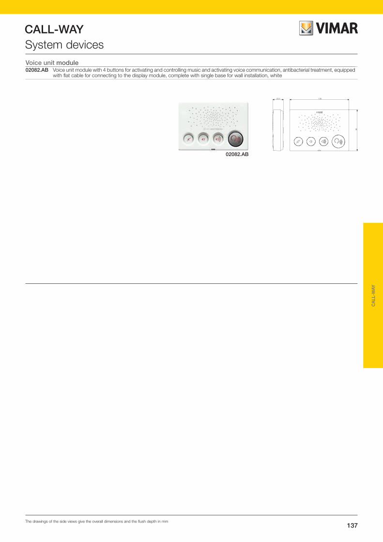
CALL-WAY
137The drawings of the side views give the overall dimensions and the flush depth in mm
CA
LL-W
AY
02082.AB
90
13023,5
System devicesVoice unit module02082.AB Voice unit module with 4 buttons for activating and controlling music and activating voice communication, antibacterial treatment, equipped
with flat cable for connecting to the display module, complete with single base for wall installation, white

CALL-WAY
138
Corridor displayDisplay for viewing of events that can occur during system operation.The viewable events are:• calls• presences• failures• alarms
At rest, the default configuration has an analogue clock or a screensaver displayed, if any system events occur the display changes and their list is shown. It is possible to associate the views with an acoustic signal, in the form of both an audible alarm and a voice announcement.
Fixing bracketWall fixing bracket for corridor display for Call-Way system.
Ethernet serial converterThe device transfers data from the secondary line to a PC in corridor display mode.
System devices
Technical datarated supply voltage 12-24 Vdc ± 10%current absorption 200 mAmax terminal cable section 2.5 mm2
operating temperature 5°C - + 40°C (indoor)relative humidity during operation max. 90%
Technical specifications• 9 modules of 17.5 mm
Conformity to StandardsEMC directiveStandards EN 55022, EN 55024
The display and acoustic signals are fully customizable in terms of:• type of display at rest (time, customized text, background images, etc.)• size and colour of the text• description of the types of event• blinking of the types of event• duration, tone and repetition of the audible alarm• content of the voice messages
It is to be anchored to a wall or ceiling with a fixing bracket, supplied separately.
E T H E R N E T
RS232 – – + +
02079ETHERNET / RS485 SNIFFER
Call-Way
COLLEGAMENTO RETEVERSO SWITCH ETHERNET (cavo UTP)
– +
+, – : ingressi alimentazione di sistemaD1, D2: collegamento dati
uscite ausiliarie per alimentazione apparati vicini
Front view 02079
NETWORK CONNECTIONTO ETHERNET SWITCH(UTP cable)
Auxiliary outputs for power equipment neighbors
+, – : system power supply terminalsD1, D2 : data connection

CALL-WAY
139The drawings of the side views give the overall dimensions and the flush depth in mm
CA
LL-W
AY
02097
02098
02079
System devicesCorridor display02097 Display to show the events of the Call-Way system, wall mounting. Supplied without fixing bracket
Fixing bracket02098 Wall fixing bracket for display for Call-Way system
Ethernet serial converter02079 Ethernet/RS485 interface installation on DIN rail (60715 TH35), occupies 9 modules size 17.5 mm

CALL-WAY
140
Call button The device performs the function of calling nursing personnel and patient reassurance by means of a specific pilot lamp. It is connected by conventional wiring to the display module 02081.AB or the communication terminal 02080.AB. Conformity to Standards
LV Directive, EMC DirectiveStandards EN 60950-1, EN 61000-6-3, EN 61000-6-1
Pull-cord call button The device is equipped with 1.5 m of cord together with a red disc and it is usually installed in bathrooms and showers. It is connected by traditional wiring to the display module 02081.AB or to the communication terminal 02080.AB for the room which acts as an interface with the Bus line.
Conformity to StandardsLV Directive, EMC DirectiveStandards EN 60950-1, EN 61000-6-3, EN 61000-6-1
NOTEThe display module and the communication terminal are provided for connecting call buttons with three outputs capable of drawing a maximum current of 100 mA each (the other two outputs are used for connecting the ceiling pull and the call cancelling button).If there are any rooms with more than three beds, NC configured bed call modules can be connected in parallel, thus losing the view on the display of the bed that made the call.Or you can use a card with 8 inputs/8 outputs.
Cancellation button The device performs the function of cancelling the call and sig-nalling the presence of personal to the system; it is equipped with a buzzer for the acoustic signal if calls come from other rooms when the health personnel are not in the control room (calls are forwarded to the room where the personnel are pro-viding assistance). It is connected by traditional wiring to the display module 02081.AB or to the communication terminal 02080.AB for the room which acts as an interface with the Bus line.
Conformity to StandardsLV Directive, EMC DirectiveStandards EN 60950-1, EN 61000-6-3, EN 61000-6-1
System devices
Technical datasupply voltage 24 Vdc ± 20% SELVcurrent absorption 30 mA max
Technical datasupply voltage 24 Vdc ± 20% SELVcurrent absorption 30 mA max
Technical datasupply voltage 24 Vdc ± 20% SELVcurrent absorption 125 mA max
Mini keypad Mini keypad for nursing staff with an anti-strangulation function and two buttons for switching a light on and off.

CALL-WAY
141The drawings of the side views give the overall dimensions and the flush depth in mm
CA
LL-W
AY
46,5
36
14503.AB
46,5
36
14504.AB
46,5
36
14501.AB
System devices
Call button14501.AB Call button for NO and NC circuits with red reassurance light, antibacterial treatment, white - 2 modules
Pull-cord call button14503.AB Pull-cord call button for NO and NC circuits with red reassurance light, antibacterial treatment, white - 2 modules
Cancellation button with buzzer14504.AB Cancellation button for NO and NC circuits with acoustic signal for receiving other calls and green indicator light, antibacterial treatment,
white - 2 modules
02089.AB
Mini keypads02089.AB Mini keypad with 2 light controls, anti-bacterial material, anti-strangulation function

CALL-WAY
142
System devicesLanding LED lampThe device, installed in hallways and near room doors, uses colour combinations to show the different types of calls made by patients or the nursing staff and any diagnostic messages.
Conformity to StandardsLV Directive, EMC DirectiveStandards EN 60950-1, EN 61000-6-1, EN 61000-6-3
CALLER TYPE OF CALLIDENTIFICATION
(DIN VDE 0834-1:2000-04)WARNING CALL METHOD
PATIENTS
Normal call
Nurse call
The patient makes a call from the room to the nurse's station. The patient (or a family member), presses the button on the communication terminal or on the display module (it is equivalent to a call from a keypad).
Bathroom/WC callThe patient makes a call from the bathroom to the nurse's station.
ASSIGNED STAFF (nurse)
Call for assistance
Emergency call (second presence)
The nurse, with presence inserted, repeats the call from the mini keypad or the button on the communication terminal or display module.
Bathroom/WC assistance callThe nurse, with presence in bathroom inserted, repeats the call from the bathroom.
Doctor call (emergency)
Emergency call
The nurse must hold down the call button for 3 seconds or press, again for 3 sec and with presence inserted, the button on the communication terminal or display module.
Bathroom/WC doctor callThe nurse, with presence in bathroom inserted, must pull the bathroom ceiling pull-cord for approximately 3 sec.
DIAGNOSTICS Diagnostics call -Possible when connecting an electro-medical instrument with a clean contact output.
LIGHT ON steady LIGHT flashing at intervals of 1 sec LIGHT flashing at intervals of 0.3 sec

CALL-WAY
143The drawings of the side views give the overall dimensions and the flush depth in mm
CA
LL-W
AY
System devices
02084
Landing LED lamp02084 Landing LED lamp, four colours (green, white, red, amber), wall installation

CALL-WAY
144
System devicesLine coupler The device enables interfacing between the Ethernet and the secondary backbone of the system in order to share and/or transfer the data messages between the modules; in addition, it creates functional separation between the backbones (if a line coupler shorts the other backbones continue to work correctly).The device is equipped with three LEDs that enable displaying the state of operation. Each line coupler can be connected with up to 127 devices (display modules, communication terminals, telephone cou-plers) of the Call-way system.
Technical specifications• 9 modules of 17.5 mm
Conformity to StandardsLV Directive, EMC Directive, Standards EN 60950-1, EN 61000-6-1, EN 61000-6-3
Technical data 02094supply voltage 12-24 Vdc ± 10%current absorption 250 mAoperating temperature 5°C - + 40°C (indoor)relative humidity during operation max. 90%
02094ADL - EF COUPLER
Call-Way
M2
NO NC C
M1 F2 F1 D2 D1 – + – – ++
DORSALE SECONDARIA+, – : ingressi alimentazione di sistemaD1, D2: collegamento datiF1, F2: collegamento foniaM1, M2: collegamento musica
USCITE AUX ALIMENTAZIONE+, +, –, – : uscite ausiliarie per alimentazione apparati vicini
Front view 02094
SECONDARY BACKBONE+, – : system power supply terminalsD1, D2 : data connectionF1,F2 : telephone connectionM1,M2 : music connection
AUX POWER SUPPLY OUTPUTS+, +, –, – : auxiliary outputs for power equipment neighbors

CALL-WAY
145The drawings of the side views give the overall dimensions and the flush depth in mm
CA
LL-W
AY
System devices
02094
Line coupler with Ethernet and sound system management02094 Line coupler with Ethernet and voice control, 24 Vdc power supply, installation on DIN rail (60715 TH35), occupies 9 modules of 17.5 mm

CALL-WAY
146
Telephone couplerThis device is used to interface the system with paging devices and telephone switchboards, to transmit a music channel or make announcements in the single rooms and single wards or general announcements using normal telephones. It allows calls by medical staff to the room and handles two-way com-munication. The telephone coupler allows communication with fixed telephones via a PABX interface while the connection to the VOX local telephone is made directly via dedicated terminals and regardless of whether there is a PABX interface.
Technical specifications• 9 modules of 17.5 mm
Conformity to StandardsEMC directiveStandards EN 60950-1, EN 61000-6-1, EN 61000-6-3
System devicesTechnical datasupply voltage 24 Vdc ± 20% SELVcurrent absorption 75 mAoperating temperature 5°C - + 40°C (indoor)
ESPA 4.4.4 interfaceSerial interface for connection without PC between Call-Way and a DECT/pager system or equipped with ESPA 4.4.4 inter-face, installation on DIN rail (60715 TH35), occupies 9 modules size 17.5 mm. The device should be connected to the second-ary backbone and forwards calls to apparatus that manages the ESPA 4.4.4 protocol on serial line RS232.
Technical specifications• 1 power supply detected LED• occupies 9 modules size 17.5 mm
Conformity to StandardsEMC DirectiveStandards EN 60950-1, EN 61000-6-1, EN 61000-6-3
Technical datarated supply voltage 12-24 Vdc ± 10%current absorption 40 mAmax terminal cable section 2.5 mm2
operating temperature 5°C - + 40°C (indoor)relative humidity during operation max. 90%
M2
GND RX
RS232 per ESPA 4.4.4
TX
M1 F2 F1 D2 D1 – + – – ++
– +
F1, F2: collegamento foniaM1, M2: collegamento musica
DORSALE SECONDARIA+, – : ingressi alimentazione di sistemaD1, D2: collegamento dati
USCITE AUX ALIMENTAZIONE+, +, –, – : uscite ausiliarie per alimentazione apparati vicini
ESPA 4.4.4GNDTXRX
: collegamenti linea RS232
02095SERIAL DATA INTERFACE
ESPA 4.4.4
Call-Way
Front view 02095
SECONDARY BACKBONE+, – : system power supply terminalsD1, D2 : data connection
: RS232 line connections
F1,F2 : telephone connectionM1,M2 : music connection
AUX POWER SUPPLY OUTPUTS+, +, –, – : auxiliary outputs for power equipment neighbors
TRIMMER.• ANNUNCI: volume annunci vocali delle chiamate in corso
verso l’interfaccia telefonica (PABX).
• MUSICA: volume verso canale annunci/diffusione musicale.
• FONIA: volume audio da fonia a telefono locale (VOX).
• VOX: volume fonia da interfaccia telefonica (PABX) o da telefono locale (VOX).
S1.Dip-switch 1,2,3,4,5: impostazione indirizzo accoppiatore telefonico.
Dip-switch 6,7,8: impostazione del tipo di segnalazione acustica (gong) di avviso messaggi (1,2,3 toni).
XB.+,- : Alimentazione 24 V d.c. SELV
D1, D2: Collegamento dati.
F1, F2: Collegamento fonia.
M1, M2: Collegamento diffusione musicale.XL.A, B: Collegamento linea telefonica come interno analogico PABX. Alimentazione 29 mA dc, impegno mediante induttore sintetico, composizione multifrequenza/impulsi.
XV.A, B: Collegamento telefono locale (VOX). Alimentazione 27 mA dc
XH.IN, GND: Ingresso annunci vocali da PC (file WAVE).Segnale sbilanciato livello tipico 2 Vpp (uscita cuffie PC).
XM.IN, GND: Ingresso canale annunci/diffusione musicale. Segnale sbilanciato livello 2 Vpp (uscita cuffie PC).
REGOLAZIONI INDIRIZZOPLS TEL M/F RUN
IN GND IN GND A B A BXH XM XV
M2 M1 F2 F1 D2 D1 +–XBXL
S1
1
ONDIP
2345678
ANNUNCI MUSICA FONIA VOX TONO GONG DL7
DL1
DL3
DL5
Regolazione TRIMMERRotazione in senso orario = aumento del volume
Rotazione in senso antiorario = diminuzione del volume
02078PHONE COUPLER
Call-Way
• TONO: volume toni segnalazione libero/occupato da telefono locale (VOX).
• GONG: volume tono segnalazione di un annuncio o di entrata in modalità fonia.
Front view 02078
XB+, – : Power supply 24 Vdc SELVD1, D2 : Data connectionF1, F2 : Voice connectionM1, M2 : Music speaker connection
XHIN, GND: notice input from PC (WAVE file)Unbalanced signal typical 2 level Vpp (PC hearphones output)
XHIN, GND: notice channel/sound system input. Unbalanced signal typical 2 level Vpp (PC hearphones output)
XV.A, B: local phone connection (VOX). 27 mA dc supply voltage
S1Dip-switch 1,2,3,4,5: address phone coupler setDip-switch 6,7,8: set of the signal (GONG) for message notice (1,2,3 tones)
XLA, B: phone line connection as an analog extension PABX. 29 mA dc supply voltage through synthetic inductor, multi-frequency/pulse composition
TRIMMER• NOTICE: notice volume of calling in progress towards the
phone interface (PABX).• MUSIC: volume for notice channel/sound system• SOUND: audio volume from sound to local phone (VOX)• VOX: sound volume fron phone interface (PABX) or local
phone (VOX)
• TONE: tone volume for free/busy state fron local phone (VOX)
• GONG: tone volume for notice signalling or in sound mode switch
TRIMMER: clockwise rotation = volume increasinganticlockwise rotation = volume decreasing

CALL-WAY
147The drawings of the side views give the overall dimensions and the flush depth in mm
CA
LL-W
AY
System devicesTelephone coupler02078 Telephone coupler, 24 Vdc power supply, installation on DIN rail (60715 TH35), occupies 9 modules size 17.5 mm
02078
ESPA 4.4.4 interface02095 Serial interface for connection without PC between Call-Way and a DECT/pager system or equipped with ESPA 4.4.4 interface, installation
on DIN rail (60715 TH35), occupies 9 modules size 17.5 mm
02095

CALL-WAY
148
System devices8-channel indication connection moduleThe device has 8 call/reset inputs and 8 outputs for landing lamps; there are also 4 technical inputs (potential alarms from electro-medical equipment).Call/reset inputs and lamps can be configured only via Call-way software and independently in terms of the room they are associated with and the function they need to perform. The only constraint is that all card channels must belong to the same ward.Each call/reset input has an output for an LED or reassurance light indicating the corresponding button has been pressed.All inputs can be configured as normally open or normally closed.
Technical specifications• 1 power supply detected LED• occupies 8 modules size 17.5 mm
Conformity to StandardsEMC directiveStandards EN 60950-1, EN 61000-6-1, EN 61000-6-3
Technical datarated supply voltage 12-24 Vdc ± 10%current absorption 20 mAmax LED output current 100 mAmax lamp output current 250 mAoperating temperature 5°C - + 40°C (indoor)relative humidity during operation max. 90%
XAB2
XAB1
XA72
XA71
XA62
XA61
XA52
XA51
XA42
XA41
XA32
XA31
XA22
XA21
XA12
XA11GND
XB : BUS DI SISTEMA / SYSTEM BUSXA : INGRESSI / INPUTS (1-CALL, 2-LED)XT : INGRESSI TECNICI / TECHNICAL INPUTSXS : USCITE / OUTPUTSXF : BUS FONIA /SPEECH BUS
+V GND +V GND +V GND +V
XS8 XS7 XS6 XS5 XS4 XS3 XS2 XS1 XSC XT6 XT5 XT2 XT1
XT8 XT7 XT4 XT3
XF8
XB
XF7 XF6 XF5 XF4 XF3 XF2 XF1
M2 M1 F2 F1 D2 D1 – +
Descrizione morsetto connettore XB
–+
Alimentazione (2 x 1,5 mm2)
Dati/Fonia/MusicaSSTP 4cp
D1D2F1F2M1M2
D1D2F1F2M1M2
Front view 02096
Description of terminals
+, – : system power supply inputsD1, D2 : data connectionF1, F2 : voice unit connectionM1, M2 : music connectionXan-1 (*) : call input (bed/bathroom)Xan-2 (*) : reassurance LED output (bed/bathroom)XT1, 2, 5, 6 : technical/diagnostic inputs for alarms from external devicesXS1....8 : landing indicator lamp outputs+V / GND : power supply positive and negative for call unit
(*) n: from 1 to 8 v. terminals.
XB connector terminal description
Data/Telephone/MusicSSTP 4cp
Power supply (2 x 1,5 mm2)

CALL-WAY
149The drawings of the side views give the overall dimensions and the flush depth in mm
CA
LL-W
AY
System devices
02096
8-channel indication connection module02096 Programmable card 8 inputs 8 outputs for managing multiple rooms, installation on DIN rail (60715 TH35), occupies 8 modules size 17.5 mm

CALL-WAY
150
System devicesPower supply The power supply is auto-protected against short circuits and can be installed in a junction box or on EN 50022 rails with the specific support provided. It is recommended to always have a safety switch for the elec-tric power supply circuit of the device 02090.
Technical specifications• rated supply voltage: 110-120 / 220-240 Vac, 50/60Hz• consumption:- 110-120 Vac: 3.2 A- 220-340 Vac: 1.6 A• output voltage: 24 Vdc SELV: voltage adjustment: 21-28 Vdc,
tolerance: ± 1% • total max output current: 6.5 A• operating temperature: -10°C - + 60°C (indoor)• dimensions: 199 x 110 x 50 mm
Conformity to StandardsLV directive Standard EN 60950-1EMC directive Standards EN 61000 - 6 - 1, EN 61000 - 6 - 3
L-N: Morsetti dialimentazione
120-230 V
Contatto dimessa a terra
LED verde:
• acceso con piena luminosità:normale funzionamento.
• acceso con luminosità tenue:dispositivo in stato di protezione.
-V: Uscita negativo alimentazione +V: Uscita positivo alimentazione
L N(AC)
-V -V +V +VV
ADJ
Trimmer regolazione
tensione di uscita
Connections 02090
L-N: 120-230 Vpower supply
terminals
Earthingcontact
Green LED:• on with full brightness: normal operation• on with faint brightness: device in state of protection
Output voltage
adjustment trimmer
-V: power supply negative output +V: power supply positive output

CALL-WAY
151The drawings of the side views give the overall dimensions and the flush depth in mm
CA
LL-W
AY
System devices
02090
Power supply02090 Power supply unit with 24 Vdc output SELV 6,5 A, power supply 110-120/220-240 Vac 50/60 Hz
03061
Cable category 5e FTP03061 Cable Cat. 5e, shielded with 4 pairs, 24 AWG with LSZH sheath, grey - 305 m

CALL-WAY
152
System devicesPrismatic indicator units - 14387... To be used, for the Call-way system, with lamps 14771
Conformity to StandardsLV directive
71 m
m71
mm
14644
14603 x 314387.B
14387.R
14387.V
Installation of prismatic indicator units for landing indicator
204
83
Installation of prismatic indicator units with Isoset wall-mounting box 2+2+2 modules - vertical installation
14813
14387.B
14387.R
14387.V
Installation of prismatic indicator units with flush mounting box 3 modules V71303 with joint V71562
V71303 x3+ joint V71562
286,
5*
*Dimensions in mm
33*
33*
14612 x3 14652.01 x3
14387.B
14387.R
14387.V
Technical datalamp supply voltage 24 Vaclamp current absorption 3 W / 24 Vac

CALL-WAY
153The drawings of the side views give the overall dimensions and the flush depth in mm
CA
LL-W
AY
System devices
14387.R14387.B 14387.V
56
24
Prismatic indicator units14387.B Prismatic indicator unit 230 V~ 3 W max for lamps 14770, 14771, 14776 and 14777, white diffuser - 2 modules.
Supplied without lamp
14387.R As above, red diffuser14387.V As above, green diffuser

CALL-WAY
154
Call button*The device performs the function of calling nursing personnel and patient reassurance by means of a specific pilot lamp. It is equipped with a 7-pin DIN socket for the mini keypad and it is usually installed near to a headboard. It is connected by tradi-tional wiring to the display module 02081 or to the communica-tion terminal 02080 for the room which acts as an interface with the Bus line and the landing lamp.
Conformity to StandardsEMC directive
Technical datasupply voltage 24 Vdc ± 20% SELVcurrent absorption 30 mA max
* Spare for first generation Call-way
* Spare for first generation Call-way, compatible only with 02080 and 02081
Protocol converter*The device enables interfacing the control unit (PC) with the sys-tem and generating the main backbone. The protocol converter is connected to the control unit (PC) via the serial cable DB9M-DB9F supplied and to the main back-bone with the Bus cable.Each protocol converter can manage up to 127 line couplers 02092.
Technical specifications• supply voltage: 24 V d.c. ± 20% SELV• current absorption: 25 mA• operating temperature: 5°C - + 40°C (indoor)• ABS box, for desktop use• dimensions: 82x110x40 mm
Conformity to StandardsEMC directiveStandards EN 55022, EN 55024,
Devices
02091CONVERTITORE DI PROTOCOLLO
RS232RS485
RS485
RS232
DORSALE PRINCIPALE
RUN
D2D1
GNDRX
TX
–+
UNITÀ CENTRALE
UNITÀ CENTRALERS232
GNDRX
TX
DORSALEPRINCIPALE:Connettore RJ45 o morsetto maschio con terminali a vite
SERIALE VERSO PC:Connettore DB9M-DB9F o morsetto maschio con terminali a vite
Schema collegamento cavoper PC con morsetto maschio
con terminali a vite
Connettore “D”maschio a 9 poli
GNDTX RX
Collegamento datidorsale principale
LED RS232
LED RS485
LED RUN
Alimentazione24 V d.c. SELV
D2 D1 – +
2 3 5
Connettore “D”femmina a 9 poli
RJ45:pin 1,2,3 = + pin 4 = D2 pin 5 = D1pin 6,7,8 = -
Front view 02091
Main backbonedata connection
9 pole femaleconnector "D"
9 pole maleconnector "D"
Power supply24 Vdc SELV
Cable connection diagramfor PC with male terminal
with screw terminals
SERIAL PORT TO PC:DB9M-DB9F connector or male terminal with screw terminals
MAIN BACKBONE:RJ45 connector or male terminal with screw terminals

CALL-WAY
155The drawings of the side views give the overall dimensions and the flush depth in mm
CA
LL-W
AY
46,5
36
14502
Call button with DIN socket*14502 Call button with 7-pin DIN socket for connection with mini keypad, red reassurance light - 2 modules
∆ 02088∆ 02087∆ 02086
Mini keypads*∆ 02086 Simple mini keypad. (IP54 protection rating)
∆ 02087 Simple mini keypad with 1 light control. (IP54 protection rating)
∆ 02088 Simple mini keypad with 2 light controls. (IP54 protection rating)
* Spare for first generation Call-way, compatible only with 02080 and 02081
* Spares for first generation Call-way, compatible only with 02080, 02081 and 14502
* Spare for first generation Call-way
∆ 02091
Protocol converter*∆ 02091 Protocol converter for connection to PC power supply 24 Vdc, complete with cable
Devices
∆ Available until stocks last

CALL-WAY
156
Antibacterial Plana devicesScopeControl (switching on and off) of ohmic-inductive loads:• light circuits for:- lighting devices with incandescent lamps- lighting devices with fluorescent lamps, with and without pow-
er factor correction• dedicated circuits for:- motor-driven appliances (fans, extractor fans, suction hoods,
etc.)- controlled socket outlets
To make systems pursuant to art. 4 of Italian Ministerial Decree 14/06/1989 no. 236 on the elimination of architectural barriers, use luminous controls.
Customizing the buttons of control devicesVIMAR laser technology enables duplicating any symbol, logo or brand on the buttons of control devices with the highest ac-curacy and assurance of indelebility.The following are created by laser:• all the symbols of the articles in the catalogue• the symbols and lettering in the library• symbols, lettering, trademarks and logos on request
Technical specifications• rated voltage: 250 V~ • rated current:- 10 A for the buttons- 16 AX for devices designed to control circuits of fluorescent lamps with power factor correction• contact opening gap: > 3 mm• insulation resistance: > 5 MΩ at 500 Vdc• dielectric strength: > 2000 V~• minimum breaking capacity: 200 position changes at 1.25 In, 275 V~ cos ϕ 0.3 and 200 po-
sition changes at 1.2 In, 250 V~, with load of tungsten filament lamps (excluding buttons)
• minimum electrical life: - 40,000 position changes at In, 250 V~, cos ϕ 0.6 - 10,000 position changes for devices marked 10 AX (5,000 for
devices marked 16 AX) at In, 250 V~, with load of fluorescent lamps
• balanced and silent rocking action for switches, inverters and buttons
Conformity to StandardsLV directiveStandard EN 60669-1
Load status signalling unit
14001.AB
00936...
Pre-wired signalling unit for locating the control in the dark
00931
14001.AB
Funzione di localizzazionedel comando al buio:
spia sempre accesa
Funzione di segnalazione dello statodi funzionamento di utilizzatori
non in vista dal punto di comando:spia accesa a lampada comandata accesa
LN
LN
Funzione di localizzazionedel comando al buio:
spia spenta a lampada comandata accesa
LN
Connections of luminous 1P1-way switches with signalling unit
For switch location in the dark:
pilot lamp always lit
For switch location in the dark:pilot lamp unlit when
the controlled loads is ON
Indication of the operation state of appliances not visible from the operating point:
pilot lamp lit when the controlled loads is ON

CALL-WAY
157The drawings of the side views give the overall dimensions and the flush depth in mm
CA
LL-W
AY
Antibacterial Plana devices
20,5
10
14041.AB
14001.AB
14015.AB
Blank module14041.AB Blank module, antibacterial treatment, white
1P 1-way switch14001.AB 1P 16 AX 250 V~, lightable, replaceable button, antibacterial treatment, white
2P 1-way switch14015.AB 2P 16 AX 250 V~, lightable, replaceable button, antibacterial treatment, white
38,4
24
38,4
24

CALL-WAY
158
Antibacterial Plana devices
Load status signalling unit
14005.AB
00936...
Pre-wired signalling unit for locating the control in the dark
14005.AB
00931
Funzione di localizzazionedel comando al buio:
spia sempre accesa
Funzione di segnalazione dello statodi funzionamento di utilizzatori
non in vista dal punto di comando:spia accesa a lampada comandata accesa
LN
Funzione di localizzazionedel comando al buio:
spia spenta a lampada comandata accesa
LN
LN
Connections of luminous single-pole switches with signalling unit
For switch location in the dark:
pilot lamp always lit
For switch location in the dark:pilot lamp unlit when
the controlled loads is ON
Indication of the operation state of appliances not visible from the operating point:
pilot lamp lit when the controlled loads is ON
LN
LN
Funzione di localizzazionedel comando al buio:
spia sempre accesa
Funzione di segnalazione dello statodi funzionamento di utilizzatori
non in vista dal punto di comando:spia accesa a lampada comandata accesa
Connections of luminous two-pole switches with signalling unit
For switch location in the dark:
pilot lamp always lit
Indication of the operation state of appliances not visible from the operating point:
pilot lamp lit when the controlled loads is ON

CALL-WAY
159The drawings of the side views give the overall dimensions and the flush depth in mm
CA
LL-W
AY
Antibacterial Plana devices
14005.AB
14013.AB
1P 2-way switch14005.AB 1P 16 AX 250 V~, lightable, replaceable button, antibacterial treatment, white
1P reversing switch14013.AB 1P 16 AX 250 V~, lightable, replaceable button, antibacterial treatment, white
38,4
24
38,4
24

CALL-WAY
160
Antibacterial Plana devicesSingle-pole buttons
Pre-wired signalling unit for locating the control in the dark
14008.AB
00931
Load status signalling unit
14008.AB
00936...
Funzione di localizzazionedel comando al buio:
spia sempre accesa
LN
Connections of luminous single-pole buttons with signalling unit 110 V~ or 250 V~
For switch location in the dark:pilot lamp always lit

CALL-WAY
161The drawings of the side views give the overall dimensions and the flush depth in mm
CA
LL-W
AY
14008.AB
14022.AB
14052.AB
1P push button14008.AB 1P NO 10 A 250 V~, lightable, replaceable button, antibacterial treatment, white
2-module interchangeable button14022.AB Interchangeable button, 2 modules, ring lightable, antibacterial treatment, white
Special single-pole button14052.AB Button 1P NO 10 A 250 V~, with pull-cord, with 1.5 m cord and knob, antibacterial treatment, white
Antibacterial Plana devices
38,4
24
37,3
25,5 22,349

CALL-WAY
162
Antibacterial Plana devices
Universal dimmer with potentiometer
Technical specifications• Turning the load on/off with the incorporated button or normal
buttons without pilot light when off; knob dimmering;• Soft start: gradual lighting from zero to maximum or preset
lighting levels;• Flash start: used with compact fluorescent lamps, for switching
on the lamps correctly, reducing any difficulties to a minimum;• Soft end: gradual passage from light to dark;• Adjustment of leading edge (LE): used with incandescent
lamps, compact fluorescent lamps and compatible LED lamps, as well as L type electronic transformers;
• Adjustment of trailing edge (TE): used with compatible loads such as fluorescent lamps, LED lamps or C type electronic transformers;
• Protection against short-circuit when turning on together with flashing blowout detector;
• Overheating protection with flashing blowout detector;• MASTER-SLAVE function: paying attention not to exceed max-
imum power controllable by each dimmer. A MASTER device can have up to 3 SLAVE devices for a maximum total load of 2000 W (VA) corresponding to 500 W/VA max connected to each of the 4 devices. When used with fluorescent or LED lamps, the maximum power controlled from the MASTER must not exceed 40W;
• Not suitable for controlling motors (e.g. fans, ventilators);• If installing 2 dimmers in a single box, the loads that can be
controlled by each dimmer must be reduced so that their total does not exceed the maximum power that can be controlled by a single device;
• It should be used in dry, dust-free places at a temperature of between 0°C and +35°C.
Conformity to StandardsLV directive,EMC directive,Standard EN 60669-2-1.
Controllable loads in 3-wire connectionControllable loads LE (Leading Edge):
start of phaseTE (Trailing Edge):
end of phase
Incandescent 40 to 500 W 40 to 300 W
Compact fluorescent 10 to 100 W, max 5 lamps 10 to 200 W, max 10 lamps
LED 3 to 100 W, max 5 lamps 3 to 200 W, max 10 lamps
Electronic transformers for halogen
40 ÷ 300 W, max 3 inductive transformers L
40 ÷ 300 W, max 5 capacitative transformers C
Power supplies for LEDs(01874, 01875) max 10 power supplies NOT applicable
Step lights (02662) max 10 lamps NOT applicable
Controllable loads in 2-wire connectionControllable loads LE (Leading Edge):
start of phaseTE (Trailing Edge):
end of phase
Compact fluorescent lamps (with load adaptor 01873) 10 to 40 W, max 2 lamps 10 to 40 W, max 2 lamps
LED(with load adaptor 01873) 3 to 40 W, max 2 lamps 3 to 40 W, max 2 lamps
For In this configuration, you need to use the load adaptor 01873 connected in parallel with the load.
N
L
L
N
P
Portafusibile Regolatore MASTER
LampadaPulsante On/Off
14136.AB - Example of 3-wire connection
Fuse carrier MASTER dimmer
LampOn/Off push button
14136.AB - Example of 2-wire connection with load adaptor
In this configuration, you need to use the load adaptor 01873 connected in parallel with the load.
NoteThe 2-wire connection must only be used for replacing dimmers in existing electrical systems where there is no neutral wire in the dimmer box.
L
L
N
P
PortafusibileRegolatoreMASTER
Adattatoredi carico
N
S
LampadaPulsante On/Off
230 V~ 50 Hz
Fuse carrierMASTER dimmer Load adaptor
LampOn/Off push button
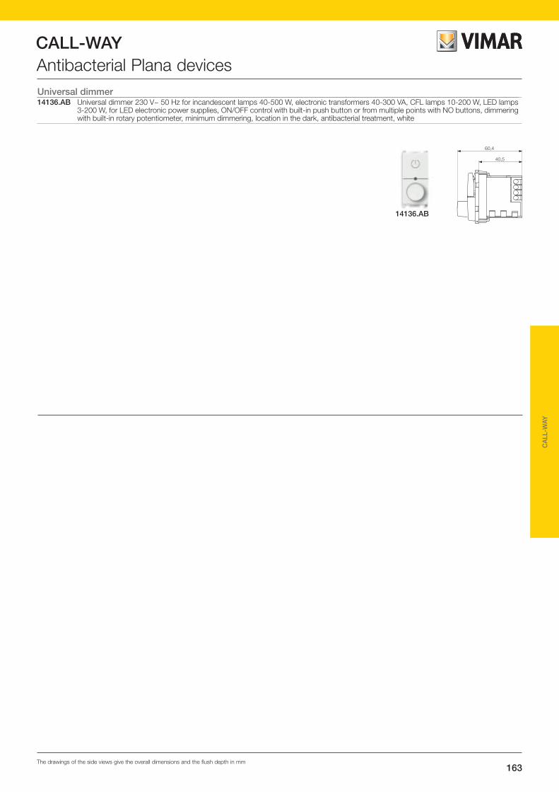
CALL-WAY
163The drawings of the side views give the overall dimensions and the flush depth in mm
CA
LL-W
AY
Antibacterial Plana devices
14136.AB
Universal dimmer14136.AB Universal dimmer 230 V~ 50 Hz for incandescent lamps 40-500 W, electronic transformers 40-300 VA, CFL lamps 10-200 W, LED lamps
3-200 W, for LED electronic power supplies, ON/OFF control with built-in push button or from multiple points with NO buttons, dimmering with built-in rotary potentiometer, minimum dimmering, location in the dark, antibacterial treatment, white
60,4
40,5 22,3
49
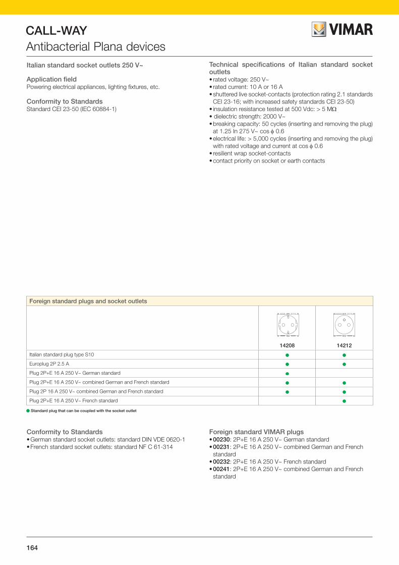
CALL-WAY
164
Antibacterial Plana devicesItalian standard socket outlets 250 V~
Application fieldPowering electrical appliances, lighting fixtures, etc.
Conformity to StandardsStandard CEI 23-50 (IEC 60884-1)
Technical specifications of Italian standard socket outlets• rated voltage: 250 V~• rated current: 10 A or 16 A• shuttered live socket-contacts (protection rating 2.1 standards
CEI 23-16; with increased safety standards CEI 23-50)• insulation resistance tested at 500 Vdc: > 5 MΩ• dielectric strength: 2000 V~• breaking capacity: 50 cycles (inserting and removing the plug)
at 1.25 In 275 V~ cos φ 0.6• electrical life: > 5,000 cycles (inserting and removing the plug)
with rated voltage and current at cos φ 0.6• resilient wrap socket-contacts• contact priority on socket or earth contacts
Conformity to Standards• German standard socket outlets: standard DIN VDE 0620-1• French standard socket outlets: standard NF C 61-314
Foreign standard VIMAR plugs• 00230: 2P+E 16 A 250 V~ German standard• 00231: 2P+E 16 A 250 V~ combined German and French
standard• 00232: 2P+E 16 A 250 V~ French standard• 00241: 2P+E 16 A 250 V~ combined German and French
standard
Foreign standard plugs and socket outlets
14208 14212
Italian standard plug type S10 • •
Europlug 2P 2.5 A • •
Plug 2P+E 16 A 250 V~ German standard •
Plug 2P+E 16 A 250 V~ combined German and French standard • •
Plug 2P 16 A 250 V~ combined German and French standard • •
Plug 2P+E 16 A 250 V~ French standard •
• Standard plug that can be coupled with the socket outlet
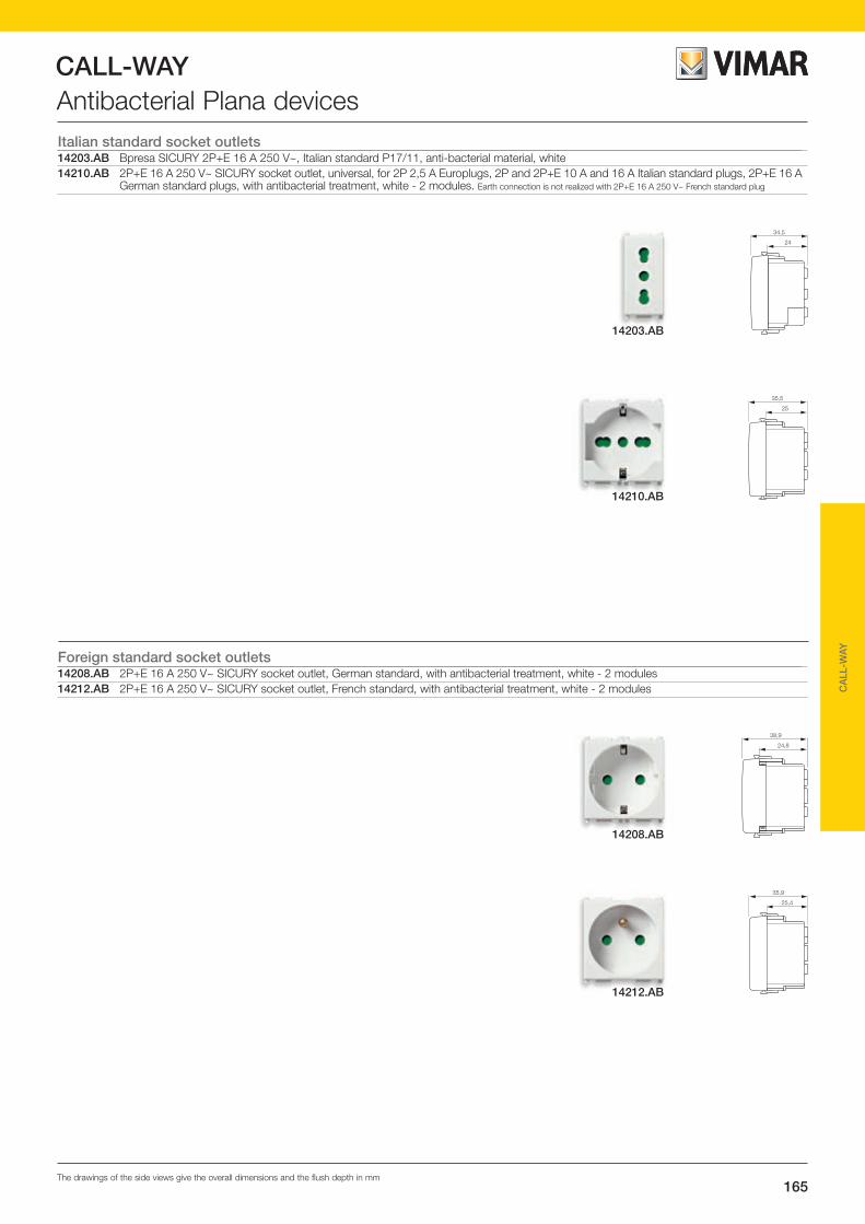
CALL-WAY
165The drawings of the side views give the overall dimensions and the flush depth in mm
CA
LL-W
AY
Antibacterial Plana devicesItalian standard socket outlets14203.AB Bpresa SICURY 2P+E 16 A 250 V~, Italian standard P17/11, anti-bacterial material, white14210.AB 2P+E 16 A 250 V~ SICURY socket outlet, universal, for 2P 2,5 A Europlugs, 2P and 2P+E 10 A and 16 A Italian standard plugs, 2P+E 16 A
German standard plugs, with antibacterial treatment, white - 2 modules. Earth connection is not realized with 2P+E 16 A 250 V~ French standard plug
Foreign standard socket outlets14208.AB 2P+E 16 A 250 V~ SICURY socket outlet, German standard, with antibacterial treatment, white - 2 modules14212.AB 2P+E 16 A 250 V~ SICURY socket outlet, French standard, with antibacterial treatment, white - 2 modules
34,5
24
14203.AB
35,5
25
14210.AB
38,9
24,8
35,9
25,4
14208.AB
14212.AB

CALL-WAY
166
Antibacterial Plana devicesSocket outlet 250 V~ for dedicated lines
Application fieldTertiary environments such as offices, medical offices, clinics, hospitals and all places where there are dedicated lines to sup-ply equipment whose operation must be guaranteed also in case of black-out (lines assisted by generators, lines fed by un-interruptible power supplies, etc.).
They differ from common socket outlets in the colour of the front (orange, red or green), which allow you to visually distinguish dedicated supply lines at the rated voltage of 230 V~.
Conformity to StandardsStandard CEI 23-50 (IEC 60884-1)
Currently, at European level, there are no regulations for match-ing the colour of the socket outlet and the type of power supply; instead, a differentiation by field of application is in practice:
• Orange: power supply protected by network/generator set with an isolating transformer
• Red: continuous power supply via UPS (uninterruptible power supply) with an isolating transformer.
• Green: safety power supply via network/generator set
14210.AB.A and 14210.AB.R 14210.AB.R
Examples of use
Shaver supply unitThey incorporate an isolating transformer of power 20 VA, pro-tected against overload, short-circuit resistant and powered via button operated directly from the plug inserted into the socket outlet.The secondary circuit, connected to the socket contacts, is separated from the primary power supply circuit by double insu-lation : this means that any additional protection on the socket contacts (shutters) is superfluous.
Technical specifications• power supply 230 V~ 50-60 Hz• output voltages: - 230 V~ for Europlugs 2P 2.5 A - 120 V~ for plugs 2P 15 A 125 V~ American standard with
non-polarised flat pins• available power: 20 VA• self-protected temperature operation• the shaver supply unit is protected against overload with a
thermal cut-off device without automatic closing. After the protection has tripped the socket contacts receive
no power; to close the circuit you must unplug the device that caused the overload and wait a few minutes for the transform-er to cool.
Conformity to StandardsLV directiveStandard EN 61558-2-5
1912,7
per eurospine 2P 2,5 A
per spine 2P standard americanospinotti piatti 15 A 125 V~ non polarizzato
Socket outlet inputs standard
For 2P 2,5 A Europlugs
For 2P 15 A 125 V~ American standard plugs with non-polarized flat blades

CALL-WAY
167The drawings of the side views give the overall dimensions and the flush depth in mm
CA
LL-W
AY
Antibacterial Plana devicesSocket outlets for dedicated power supply lines14203.AB.R 2P+E 16 A 250 V~ SICURY Bpresa socket outlet, Italian standard P17/11, with antibacterial treatment, red14210.AB.A 2P+E 16 A 250 V~ SICURY socket outlet, universal, for 2P 2,5 A Europlugs, 2P and 2P+E 10 A and 16 A Italian standard plugs, 2P+E 16 A
German standard plugs, with antibacterial treatment, orange - 2 modules. Earth connection is not realized with 2P+E 16 A 250 V~ French standard plug
14210.AB.R As above, red14210.AB.V As above, green
Shaver supply unit14290.AB Shaver supply unit with 20 VA isolating transformer, supply voltage 230 V~ 50-60 Hz, 120 V~ output voltage for 2P 15 A 125 V~
American standard plugs with non-polarized flat blades, and 230 V~ output voltage for 2P 2,5 A Europlugs, with antibacterial treatment, white - 3 modules
14210.AB.R
14210.AB.V14210.AB.A
14203.AB.R
34,5
24
35,5
25
35,5
25
35,5
25
38,4
24
14290.AB

CALL-WAY
168
Antibacterial Plana devicesTelephone socket outlet 14320 - 14321
Technical specifications- screw terminal connection
L1L2
L1TS
L2TX
L1TS
L2TX
14320 14320
L1TS
L2TX
14320
Connections 14320.AB
NOTEIn the case of socket outlets connected as in the diagram, the line between L1 and TS is broken: if the telephone is unplugged from any socket, the ones downstream would remain disconnected.To get around this problem, you can simply plug in a bridge between L1 and TS.
USA - 2P
230 volt
I D
UNIVERSALE
Example of use
Telephone socket outlet diagrams
14320RJ11
6 posizioni 4 contatti
14321RJ12
6 posizioni 6 contatti
TX TSL1L2 L1L2
TX TST2
14320.ABRJ11
6-position 4-conductor

CALL-WAY
169The drawings of the side views give the overall dimensions and the flush depth in mm
CA
LL-W
AY
Antibacterial Plana devicesSpecial socket outlet14330.AB 2P 6 A 24 V (SELV) socket outlet for plug 01620 (pins ø 3 mm, distance between centres 12,4 mm), with antibacterial treatment, white.
For auxiliary circuits
14330.AB
34,5
24
Telephone socket outlet14320.AB RJ11 phone jack, 6-position 4-conductor (6/4), screw terminals, with antibacterial treatment, white
43,1
32,6
14320.AB
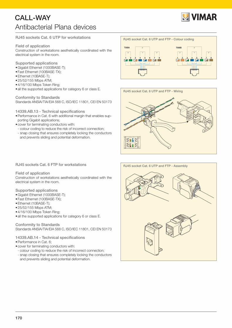
CALL-WAY
170
Antibacterial Plana devicesRJ45 sockets Cat. 6 UTP for workstations
Field of applicationConstruction of workstations aesthetically coordinated with the electrical system in the room.
Supported applications• Gigabit Ethernet (1000BASE-T);• Fast Ethernet (100BASE-TX);• Ethernet (10BASE-T);• 25/52/155 Mbps ATM;• 4/16/100 Mbps Token Ring;• all the supported applications for category 6 or class E.
Conformity to StandardsStandards ANSIA/TIA/EIA 568 C, ISO/IEC 11801, CEI EN 50173
14339.AB.13 - Technical specifications • Performance in Cat. 6 with additional margin that enables sup-
porting Gigabit applications;• cover for terminating conductors with:
- colour coding to reduce the risk of incorrect connection;- snap closing that ensures completely locking the conductors
and prevents sliding and potential deformation.
1 2 3 4 5 6 7 8
3a 4a1a
2a
1 2 3 4 5 6 7 8
2a 4a1a
3aT568A T568B
AB
87
A ABB2
1
63
45
BA
C AT. 5 e
RJ45 socket Cat. 6 UTP and FTP - Colour coding
1 2 3 4 5 6 7 8
3a 4a1a
2a
1 2 3 4 5 6 7 8
2a 4a1a
3aT568A T568B
AB
87
A ABB2
1
63
45
BA
C AT. 5 e
RJ45 socket Cat. 6 UTP and FTP - Assembly
1 2 3 4 5 6 7 8
3a 4a1a
2a
1 2 3 4 5 6 7 8
2a 4a1a
3aT568A T568B
AB
87
A ABB2
1
63
45
BA
C AT. 5 e
RJ45 socket Cat. 6 UTP and FTP - Wiring
RJ45 sockets Cat. 6 FTP for workstations
Field of applicationConstruction of workstations aesthetically coordinated with the electrical system in the room.
Supported applications• Gigabit Ethernet (1000BASE-T);• Fast Ethernet (100BASE-TX);• Ethernet (10BASE-T);• 25/52/155 Mbps ATM;• 4/16/100 Mbps Token Ring;• all the supported applications for category 6 or class E.
Conformity to StandardsStandards ANSIA/TIA/EIA 568 C, ISO/IEC 11801, CEI EN 50173
14339.AB.14 - Technical specifications • Performance in Cat. 6;• cover for terminating conductors with:
- colour coding to reduce the risk of incorrect connection;- snap closing that ensures completely locking the conductors
and prevents sliding and potential deformation.

CALL-WAY
171The drawings of the side views give the overall dimensions and the flush depth in mm
CA
LL-W
AY
Antibacterial Plana devicesRJ45 socket Netsafe Cat. 6 UTP14339.AB.13 RJ45 outlet with Netsafe connector, Cat. 6, unshielded, T568A/B universal wiring, 8 position, 110 type insulation-piercing terminals
without tool use, with antibacterial treatment, white
RJ45 socket Netsafe Cat. 6 FTP14339.AB.14 RJ45 outlet with Netsafe connector, Cat. 6, shielded, T568A/B universal wiring, 8 position, insulation-piercing terminals without tool use,
with antibacterial treatment, white
39,8
29,3
14339.AB.13
39,8
29,3 22,3
49
14339.AB.14

CALL-WAY
172
Antibacterial Plana devicesRJ45 socketRJ45 socket for the connection between the communication ter-minal 02080.AB or the display module 02081.AB and the mini keypad 02089.AB.
TV-RD-SAT 5-2400 MHz coaxial sockets
Field of application• connection of user equipment in systems for the distribution
of audio and video, analogue and digital, terrestrial, satellite and cable signals in the frequency band 5–2400 MHz
• they enable connecting a single device (e.g. TV or SAT re-ceiver)
• they can be used in Web applications via satellite and, thanks to the return channel 5-40 MHz, also for interactive functions (hotel communications and cable TV)
• the availability of direct socket outlets that allow the passage of direct current and control signals and through-line socket outlets available with three different attenuations enables op-timum use in single or centralized systems structured accord-ing to any topology.
The range• 1 direct socket outlet that allows the passage of direct current
and control signals (24 V 500 mA max)• 3 through-line socket outlets with:- connection attenuation 10 dB- connection attenuation 15 dB- connection attenuation 20 dB
The through-line socket outlets become terminals if "closed" with the specific terminal resistor 16330. They allow the pas-sage of direct current and control signals (24 V 500 mA max) through the line, but not through the user gateway (male connector).
Technical specifications• frequency range: 5-2400 MHz• output: male connector• return channel in the 5-40 MHz band• shielding efficiency: class A• cable dimensions: - internal conductor ø 3 mm max - external insulating sheath: ø 5-7 mm
Conformity to StandardsStandards EN 60728-1, EN 60728-4EMC directiveStandard EN 50083-2
How to connect
Programmes - Applications
• Terrestrial TV
Programmes - Applications
• Terrestrial radio
Programmes - Applications
• Cable TV (CATV)• Interactive hotel communications
Programmes - Applications
• Satellite TV and radio
Sintonizzatoreradio
STB(Set Top Box)
SAT
male
male
male
male
Coaxial cable connection SCART cable connection
With multiple socket outlets in cascade
With multiple shunted socket outlets
Mixed cascade/shunted
Multi-switch for distributing satellite signals
Multi-switch for distributing mixed terrestrial and satellite signals
Mixed cascade/shunted with IF-IF conversion unit for single-cable distribution of mixed terrestrial and satellite signals
Mixed cascade/shunted with modular unit for channelling terrestrial and satellite programmes in 40-862 MHz band (terrestrial)
Some examples of supported installation topologies

CALL-WAY
173The drawings of the side views give the overall dimensions and the flush depth in mm
CA
LL-W
AY
Antibacterial Plana devicesRJ45 socket14342.AB RJ45 outlet, 8-position 8-conductor (8/8), screw terminals, with antibacterial treatment, white
TV-RD-SAT, 5-2400 MHz coaxial socket outlet14300.AB.01 Coaxial TV-RD-SAT 5-2400 MHz socket outlet, single connection, with male connector, connection attenuation 1 dB, with antibacterial
treatment, white. Allows the passage of d.c. current and control signals (24 V 500 mA max)
43,1
32,6
14342.AB
32,1
22,6
14300.AB.01

CALL-WAY
174
Antibacterial Plana devices2- and 3-module cover plates14642.AB.01 2-module cover plate, technopolymer, antibacterial treatment, white14653.AB.01 3-module cover plate, technopolymer, antibacterial treatment, white
4- and 7-module cover plates14654.AB.01 4-module cover plate, technopolymer, antibacterial treatment, white14657.AB.01 7-module cover plate, technopolymer, antibacterial treatment, white
14642.AB.01
14654.AB.01
14653.AB.01
14657.AB.01

CALL-WAY
175
CA
LL-W
AY
Antibacterial Plana devices4 (2+2)-module cover plates (71 mm distance between centre)14643.AB.01 4-module cover plate (2+2, 71 mm distance between centre), technopolymer, antibacterial treatment, white
6 (2+2+2)-module cover plates (71 mm distance between centre)14644.AB.01 6-module cover plate (2+2+2, 71 mm distance between centre), technopolymer, antibacterial treatment, white
8 (2+2+2+2)-module cover plates (71 mm distance between centre)14669.AB.01 8-module cover plate (2+2+2+2, 71 mm distance between centre), technopolymer, antibacterial treatment, white
14669.AB.01
14644.AB.01
14643.AB.01

CALL-WAY
176
Installation examples
The Bus will be composed of two different types of cables:- 1 pair for the power supply (cable 2x2.5 mm);- 1 pair for data transmission (FTP cat. 5e cable)
Note.The 02096 is configured only via dedicated software, the inputs and outputs are independent of each other, the only limit is that they must belong to the same ward.It does not work in on-line mode.
Call indicatorThe figure shows an example of a floor plan showing the sys-tem's arrangement in a health care facility that needs to have a call system (signalling only) to display:- the call, type of call, and its origin (room number, bed, etc.);- the presence in the room of the healthcare personnel following
up on the call; - calls that could come from other rooms.The operating mode is VDE-0834, signalling the type of call priority and in which room it is made via the landing lamps and the combinations of the lights that come on.For more detailed information, such as the bed number, a 02081.AB or a 02097 is required.
•
•
02084•
•
14503.AB
•
14501.AB
02096
14504.AB
•02097

CALL-WAY
177
CA
LL-W
AY IN
STA
LLAT
ION
EX
AM
PLE
S
Installation examplesConnection diagram
02097or PC
02097or PC
B
Secondary backbone
02090
02094
230 V~
AB
A
Secondary backbone
02090
02094
230 V~
Secondary backbone
02090
02094
230 V~
Room 1 Room 2
14501.AB
02084
14503.AB
14504.AB
14501.AB
02084
14503.AB
14504.AB02096
Room 5 Shared bathroom
14501.AB
02084
14503.AB
14504.AB
14503.AB
14503.AB
14504.AB
14387.B
14387.R
02096
Room 3 Room 4
14501.AB
02084
14503.AB
14504.AB
14501.AB
02084
14503.AB
14504.AB02096
LEGEND: - 2x2.5 mm2 (power supply) - 1 cp FTP- Cat. 5e (data)02090 - Power supply unit02094 - Line coupler
A
B
Note: In the case of multi-backbone installation then, with multiple ADL-EF, channel 2 of the ADL-EF (via the Lantronix configurer, at the link: www.lantronix.com/support/downloads/?p=DEVICEINSTALLER) must be configured as default: with UDP protocol, the same remote port for all the devices, broadcast flag ticked and local host 0.0.0.0.

CALL-WAY
178
Installation examples
The Bus will be composed of two different types of cables:- 1 pair for the power supply (cable 2x2.5 mm);- 1 pair for data transmission (FTP cat.5e cable)
Note.When setting up it is always wise to have another 2 pairs of FTP cables because if in the future there were a need to expand the system, integrating voice trans-mission too, it would be enough to add the voice unit module 02082.AB to each display module 02081.AB thus taking action only on the configuration. The display module with the addition of the voice unit module basically becomes like a communication terminal 02080.AB.
Call indicatorThe figure shows an example of a floor plan showing the sys-tem's arrangement in a health care facility that needs to have a call system (signalling only) to display:- the call, type of call, and its origin (room number, bed, etc.);- the presence in the room of the healthcare personnel following
up on the call; - calls that could come from other rooms.The operating mode is VDE-0834, which includes the pos-sibility of distinguishing the call priorities (normal, assistance, emergency).Without the 02097 or a PC with dedicated software, the net-work does not have an events log or the ability to merge wards automatically.
•
•02084
02081.AB
14503.AB
•
••
02989.AB 14342.AB
•
14504.AB
•02097

CALL-WAY
179
CA
LL-W
AY IN
STA
LLAT
ION
EX
AM
PLE
S
Installation examples
LEGEND: - 2x2.5 mm2 (power supply) - 1 cp FTP- Cat. 5e (data)02090 - Power supply unit02094 - Line coupler
A
B
Note: In the case of multi-backbone installation then, with multiple ADL-EF, channel 2 of the ADL-EF (via the Lantronix configurer, at the link: www.lantronix.com/support/downloads/?p=DEVICEINSTALLER) must be configured as default: with UDP protocol, the same remote port for all the devices, broadcast flag ticked and local host 0.0.0.0.
Connection diagram
02097or PC
02097or PC
B
Secondary backbone
02090
02094
230 V~
AB B
A
Secondary backbone
02090
02094
230 V~
Secondary backbone
02090
02094
230 V~
Room 1
02084
14503.AB
14504.AB
02081.AB
02089.AB
02089.AB
3
4
5
4
414342.AB
14342.AB
Room 2
02084
14503.AB
14504.AB
02081.AB
02089.AB
02089.AB
3
4
5
4
414342.AB
14342.AB
Room 3
02084
14503.AB
14504.AB
02081.AB
02089.AB
02089.AB
3
4
5
4
414342.AB
14342.AB
02095
Room N
02084
14503.AB
14504.AB
02089.AB
02089.AB
3
4
45
4
14342.AB
14342.AB
02081.AB
Paging system

CALL-WAY
180
Call-way can be integrated with other systems that support the ESPA 4.4.4 protocol (pagers/DECT).
The Bus will be composed of two different types of cables:- 1 pair for the power supply (cable 2x2.5mm2);- 3 pairs for data, voice and announcements/music channel
transmission respectively (FTP cat. 5e cable).Alternatively a single SSTP cable can be used.
Note.For only hands-free communication between two communication terminals only the ADL-EF is needed: 02094.
Voice communicationIn the layout illustrating the system setup in a healthcare facility, there is the need to have a call system that also allows voice communication; the room device that is used is the communi-cation terminal 02080.AB. The device's display will show:- the call, type of call, and its origin (room number, bed, etc.);- the presence in the room of the healthcare personnel following
up on the call; - calls that could come from other rooms.The voice unit part of the device will enable:- hands-free communication between two parties (patient -
nurse, nurse - nurse, nurse - physician) with the two modes "hands free" and "push to talk";
- transmitting a music channel (which will be promptly discon-tinued in the event of a call or announcement);
- making room, ward or general announcements (via the tel-ephone coupler connected to the system);
- communication with fixed telephones (via PABX switchboard) or normal DECT;
Installation examples
•
•
0208414503.AB
•
••
02989.AB 14342.AB
•
14504.AB
•02097
02080.AB

CALL-WAY
181
CA
LL-W
AY IN
STA
LLAT
ION
EX
AM
PLE
S
Installation examplesConnection diagram
LEGEND: - 2x2.5 mm2 (power supply) - 1 cp FTP-Cat. 5e (data) - 2 cp FTP-Cat. 5e (voice/music)02090 - Power supply unit02094 - Line coupler
Cables B and C can be grouped in a single SSTP cable (Cat.6 4 twisted pairs individually shielded)
A
B
C
02097or PC
02097or PC
B B
Secondary backbone
Phone ex-tensions
AB
C C
C C CB B
A
02090
02094
230 V~
Secondary backbone
02090
02094
230 V~
Room 1
02084
14503.AB
14504.AB
02080.AB
02089.AB
02089.AB
3
4
5
4
414342.AB
14342.AB
Room N
02084
14503.AB
14504.AB
02089.AB
02089.AB
3
4
45
4
14342.AB
14342.AB
02080.AB
02080.AB
Room 2
02084
14503.AB
14504.AB
02089.AB
02089.AB
3
4
5
4
414342.AB
14342.AB
02080.AB
Room 3
02084
14503.AB
14504.AB
02089.AB
02089.AB
3
4
5
4
414342.AB
14342.AB
Secondary backbone
02090
02094
230 V~
Note: In the case of multi-backbone installation then, with multiple ADL-EF, channel 2 of the ADL-EF (via the Lantronix configurer, at the link: www.lantronix.com/support/downloads/?p=DEVICEINSTALLER) must be configured as default: with UDP protocol, the same remote port for all the devices, broadcast flag ticked and local host 0.0.0.0.
DECT system
02078
PABX

182
The system for networking the entire facility.
Communicating, transferring and sharing data, images and videos of any size needs secure and fast connections. The Netsafe structured cabling system connects all the work environments in a facility. The system consists of a very wide range of tools: versatile solutions that are easy to install and feature great performance, for copper and fibre optic networks, they provide an extensive range of action.
RJ45 AND TELEPHONE SOCKET OUTLETS.
Cat. 5, 6 and 6A connections for different types of UTP and FTP wiring.

183
CABLES AND CORDS.
Enable 360° connection: 4-pair twisted cables, fibre optic, with PVC or LSZH outer jacket and patch cords for high-performance transmission.
PATCH PANELS.
Rack units complete with RJ45 connectors for horizontal distribution or terminations of devices in enclosures and cabinets.
ENCLOSURES AND CABINETS.
Metalwork ideal for housing patch panels and power panels in local area networks (LAN), from 6 to 42 rack units.
184
NETSAFE
Catalogue section

185
NETSAFE
NE
TSA
FE
SELECTION GUIDE from page 186
GENERAL CHARACTERISTICS from page 188
RJ45 SOCKETS from page 190
CABLES AND CONNECTORS from page 200
PATCH PANELS from page 204
CABLES AND CORDS from page 206
ENCLOSURES AND CABINETS from page 212
10” S.O.H.O. SYSTEM from page 220
POWER PANELS from page 222

186
NETSAFESelection guideRJ45 sockets Series
Eikon Arké Idea Plana 8000grey white Next grey white grey white white Silver ivory
Category Wiring without using tools
Cat. 5e UTP20338.8 20338.8.B 20338.8.N 16358.8 16358.8.B 14338.8 14338.8.SL 08458.8
20339.11 20339.11.B 20339.11.N 19339.11 19339.11.B 16359.11 16359.11.B 14339.11 14339.11.SL 08459.11
Cat. 6 UTP 20339.13 20339.13.B 20339.13.N 19339.13 19339.13.B 14339.13 14339.13.SL
Cat. 6 FTP 20339.14 20339.14.B 20339.14.N 19339.14 19339.14.B 14339.14 14339.14.SL
Cat. 6A FTP 20339.16 20339.16.B 20339.16.N 19339.16 19339.16.B 14339.16 14339.16.SL
Category 110 compatible wiring
Cat. 5e UTP 20339.4 20339.4.B 20339.4.N 16359.4 16359.4.B 14339.4 14339.4.SL 08459.4
Cat. 5e FTP 20339.5 20339.5.B 20339.5.N 16359.5 16359.5.B 14339.5 14339.5.SL 08459.5
Cat. 6 UTP 20339.6 20339.6.B 20339.6.N 16359.6 16359.6.B 14339.6 14339.6.SL 08459.6
20338.8
RJ45 connectors CodeCategory Wiring without using tools 110 compatible wiring
Cat. 5e UTP 03009.11
Cat. 5e FTP 03009.5
Cat. 6 UTP 03009.13
Cat. 6 FTP 03009.14
Cat. 6A FTP 03009.16
03009.14
Patch module for DIN rail (60715 TH35)Category Code
Cat. 6 UTP 03002.13
03002.13
Cables and connectors CodeCopper cables Category Jacket 305 m 500 m 1000 m 2000 m
Cat. 5e U/UTPPVC 03050 03050.B
LSZH 03051
Cat. 5e F/UTPPVC 03060
LSZH 03061
Cat. 6 U/UTP LSZH 03071
Cat. 6 F/UTP LSZH 03076
Cat. 6A S/FTP LSZH 03086
Fibre optic cables Number of fibres
4 LSZH 03150.1 03150.2
8 LSZH 03151.1 03151.2
Fibre optic connectors Category 62.5/125 µm 50/125 µm
ST 03106.ST
SC 03105.SC 03106.SC
03086
03050
03150.1
03105.SC
Patch cords CodeCopper Category 20 cm 50 cm 1 m 2 m 3 m 5 m
Cat. 5e U/UTP 03017.05 03017.1 03017.2 03017.3 03017.5
Cat. 5e F/UTP 03018.1 03018.2 03018.3 03018.5
Cat. 6 U/UTP 03019.02 03019.1 03019.2 03019.3 03019.5
Cat. 6 S/FTP 03020.1 03020.2 03020.3 03020.5
Cat. 6A S/FTP 03022.1 03022.2 03022.3 03022.5
Fibre optic Category 62.5/125 µm 50/125 µm
SC 03110.SC 03111.SC
LC 03111.LC
SC and LC 03111.SC.LC
03020.1
03110.SC
UTP - U/UTP (Unscreened / Unscreened Twisted Pair): connectors and cables of Cat. 5e and Cat. 6 unshielded;FTP - F/UTP (Foil screened / Unscreened Twisted Pair): connectors and cables of Cat. 5e and Cat. 6 shielded;FTP - S/FTP (Braid screened / Foil screened Twisted Pair): connectors and cables of Cat. 6A shielded.

187
NETSAFE
NE
TSA
FE
Surface mounting enclosures and cabinets Enclosures CabinetsRack units For 10” S.O.H.O. panels For 19” panels For 19” panels
6 03206.3
8 03308
9 03209.3
12 03212.3
15 03215.3
25 03224.3
42 03242.3 - 03243.3 - 03245.3
ComplementsCopper Category 10” patch panels 19” patch panels
Cat. 3 03024.3
Cat. 5e UTP 03303.1 03024.4
Cat. 5e FTP 03024.5
Cat. 6 UTP 03303.3 03024.6
Cat. 6 FTP 03024.7
Cat. 6A FTP 03024.9
Blank 03303.E 03024.E
Fibre optic Category 19” fibre optic trays
ST 03124.ST.E
SC 03124.SC.E
Category Optical adaptors for fibre optic trays
ST 03101.ST
SC 03101.SC
LC 03101.LC
Panels Rack units 10” cable outlet panels 19” cable outlet panels
103301.1A 03200.1A (open cable outlet)
03200.1U
2 03200.2U
Rack units 10” blind panels 19” blind panels
1 03301.1U 03201.1U
2 03201.2U
3 03201.3U
Rack units 19” fixed and removable shelf
2 03204.1U - 03204.2U
Telescopic rails 03204.1UM
Rack units 10” mounting frames 19” mounting frames
1 03302.1U
2 03202.2U - 03203.2U
Rack units 19” power panels
2 03260 - 03261 - 03262
AccessoriesFan 230 V~
03256
Set of cable guide rings
03251
Lock Handle with keys
03258.3 03259.3
Metal screw and nut
03257
Rack units Spare doors
6 03206.3P
9 03209.3P
12 03212.3P
15 03215.3P
25 03224.3P
42 03242.3P - 03245.3P
Rack units Hinged opening kit
9 03209.3L
12 03212.3L
15 03215.3L
Number of wheels Set of wheels
4 03224.3R
6 03245.3R
Selection guide
03308 03224.3
03256
03258.3
03212.3P
03209.3L
03245.3R
03024.5
03301.1A
03201.2U
03204.2U
03302.1U
03261
03124.ST.E
03101.LC

188
NETSAFEGeneral characteristics
Aesthetic coordinationNetsafe is not a closed-loop system, but is both technically and aesthetically integrated with the traditional electrical system, allowing great installation versatility (flush, wall, floor and under-floor installation).
RJ45 connector sockets are available for installation on mount-ing frames in the Eikon, Arké, Idea, Plana and 8000 series, mak-
ing it possible to create computer user points that are perfectly coordinated with the electrical system present in the room.
Here can also be included socket outlets for dedicated lines and the materials for making system terminations, including the vast selection of cover plate colours, shapes and materials.
The products developed enable making networks in Cat. 5e and Cat. 6 shielded or unshielded and Cat. 6A shielded that remain stable over the years and deliver high performance. The avail-ability of RJ45 connectors that are self-crimping or that can be wired using tools, 4-pair copper cables, fibre optic products, loaded and unloaded patch panels, surface mounting cabinets and enclosures with from 6 to 42 rack units and accessories enable making different types of structured cabling to satisfy any installation requirement, from the small office of a freelancer to buildings for commercial or residential use.With Netsafe, Vimar not only provides a set of products and accessories, but also services (training, support) that accompa-ny the user and the installer over time, from the first approach to
Arké - RJ45 connector sockets Cat. 6 (19339.6) with Round cover plate in Reflex Plus.
Eikon - RJ45 connector sockets Cat. 6 (20339.6.N) with Eikon Evo, Eikon Chrome and Eikon Total Look cover plate.
Idea - RJ45 connector sockets Cat. 5e (16359.4) with Rondò cover plate in die-cast metal.
the long term, with a warranty period of 3 years after installation.
It is indisputable that high quality products are required in order to make high performance structured cabling, but in this sector the characteristics and quality of the installation itself make a difference too. This is why it is important to have the knowledge and skills that Vimar provides in the form of training courses taught by qualified industry instructors that allow electrical installers to become familiar with structured cabling in order to then "market" themselves with top-quality training to take advantage of the potential of such a sophisticated product.
Plana - RJ45 connector sockets Cat. 5e (14338.8.SL) with metal cover plate.

189
NETSAFE
NE
TSA
FE
General characteristics
Copper horizontal cablingThe copper horizontal cabling is the connection between the distribution cabinet and the work stations.Listed below are some simple but essential rules for successful implementation.
TopologyThe topology (network architecture) must be a star: all the de-vices are connected to a single control unit (fig. 1).Each RJ45 socket located near a workstation must match a similar one in the patch panel in (installed inside the distribution cabinet); the sockets are connected together by means of a 4-pair twisted cable with jacket.Any installed socket outlet can be used either as a phone or data socket outlet.
DistancesThe standards prescribe at most 100 m between the active equipment in the distribution cabinet and the user equipment.The recommended maximum distance between the socket out-let installed in the distribution cabinet and the similar one near the workstation is 90 m; the maximum total length for the patch cords and the connection to the user equipment is 10 m.It is advisable to limit the distance between two consecutive junction boxes to 30 m; use a wide radius of curvature on the raceways, to avoid damaging the cables; do not pull on cables with too much force when laying them.
CableThe only permissible cable is the twisted pair with 4 pairs twisted and braided two by two, copper mono-conductor with typical cross-section that may vary, depending on the category, from 24 AWG to 23 AWG (American Wire Gauge: a unit of measure-ment that corresponds to 24 AWG = 0.21 mm2 and 23 AWG = 0.26 mm2).The insulation of the pairs is made of polyethylene, that of the outer jacket of PVC. There are cables with an outer coating called LSZH (Low Smoke Zero Halogen), made with materials that do not contain halogens and that, in case of combustion, have very low smoke emissions. In particular installations, this type of cable is required by fire safety regulations.
Structured cabling: regulationsAll the components of a structured cabling system must com-ply with the regulatory standards that define the minimum specifications to ensure constant quality and performance over time. The job of standardizing telecommunications systems in buildings has been developed beginning in 1985 in the United States by the EIA (Electronic Industries Association) and TIA (Telecommunications Industries Association), upon request by the CCIA (computer manufacturer's association).
Conformity to StandardsANSI/TIA/EIA 568 C, ISO/IEC 11801, CEI EN 50173.
Figure 1 - Star architecture
Socket connectorEach workstation must have access to at least two RJ45 sock-ets, placed every 7/8 m2.
Warranty on Netsafe systemsAll Netsafe products are guaranteed for 3 years. In the event of operating trouble in the warranty period, once the installer has checked which of the original components is to blame for the malfunctioning, Vimar will replace the defective component free of charge.The reference wholesaler will replace any defective components upon authorization by VIMAR.

190
NETSAFERJ45 sockets Cat. 5e
RJ45 sockets Cat. 5e UTP for workstations
Field of applicationCreation of workstations aesthetically coordinated with the elec-trical system present in the room.Devices can be installed using the corresponding mounting frames and cover plates, in the same way as for the other de-vices in the series:• Eikon series: 20338.8;• Arké series: 19338.9;• Idea series: 16358.8;• Plana series: 14338.8;• 8000 series: 08458.8.
Supported applications• Gigabit Ethernet (1000BASE-T);• Fast Ethernet (100BASE-TX);• Ethernet (10BASE-T);• 25/52/155 Mbps ATM;• 4/16/100 Mbps Token Ring;• all the other supported applications for category 5, 5e or class D.
Conformity to StandardsStandards ANSIA/TIA/EIA 568 C, ISO/IEC 11801, CEI EN 50173.
20338.8, 16358.8, 14338.8, 08458.8
Technical specifications• Performance in Cat. 5e;• cover for terminating conductors with:
- colour coding to reduce the risk of incorrect connection;- snap closing that ensures completely locking the con-
ductors and prevents sliding and potential deformation.
RJ45 socket Cat. 5e UTP - Colour coding
RJ45 socket Cat. 5e UTP - Assembly

191
NETSAFE
NE
TSA
FE
RJ45 sockets Cat. 5e
IDEA
EIKON
PLANA22,3
49
22,6
33,1 8000
08458.8ivory
24,8
50
35,2
24,2
14338.8.SLSilver
33,523,6
16358.8.Bwhite
16358.8grey
14338.8white
22,3
49
33,1
23,6
20338.8.NNext
20338.8.Bwhite
20338.8grey
RJ45 socket Cat. 5e UTPRJ45 socket with Netsafe connector Cat. 5e, unshielded, T568A/B universal wiring, 8 contacts, insulation-piercing terminals without using tools
The drawings of the side views give the overall dimensions and the flush depth in mmCables, from p. 200 - Patch panels, from p. 204

192
NETSAFERJ45 sockets Cat. 5e
RJ45 sockets Cat. 5e UTP for workstations
Field of applicationCreation of workstations aesthetically coordinated with the electrical system present in the room.Devices can be installed using the corresponding mounting frames and cover plates, in the same way as for the other devices in the series:• Eikon series: 20339.4, 20339.11;• Arké series: 19339.11;• Idea series: 16359.4, 16359.11;• Plana series: 14339.4, 14339.11;• 8000 series: 08459.11.
Supported applications• Gigabit Ethernet (1000BASE-T);• Fast Ethernet (100BASE-TX);• Ethernet (10BASE-T);• 25/52/155 Mbps ATM;• 4/16/100 Mbps Token Ring;• all the other supported applications for category 5, 5e or class D.
Conformity to StandardsStandards ANSIA/TIA/EIA 568 C, ISO/IEC 11801, CEI EN 50173.
20339.4, 16359.4, 14339.4
Technical specifications• Performance in Cat. 5e;• termination of 110 compatible conductors using tool 03250.
20339.11, 19339.11, 16359.11, 14339.11, 08459.11
Technical specifications• Performance in Cat. 5e;• cover for terminating conductors with:
- colour coding to reduce the risk of incorrect connection;- snap closing that ensures completely locking the con-
ductors and prevents sliding and potential deformation.
1 2 3 4 5 6 7 8
3a 4a1a
2a
1 2 3 4 5 6 7 8
2a 4a1a
3aT568A T568B
AB
87
A ABB2
1
63
45
BA
C AT. 5 e
RJ45 socket Cat. 5e UTP - Colour coding
1 2 3 4 5 6 7 8
3a 4a1a
2a
1 2 3 4 5 6 7 8
2a 4a1a
3aT568A T568B
AB
87
A ABB2
1
63
45
BA
C AT. 5 e
1 2 3 4 5 6 7 8
3a 4a1a
2a
1 2 3 4 5 6 7 8
2a 4a1a
3aT568A T568B
AB
87
A ABB2
1
63
45
BA
C AT. 5 e
RJ45 socket Cat. 5e UTP - Assembly
RJ45 socket Cat. 5e UTP - Wiring

193
NETSAFE
NE
TSA
FE
RJ45 sockets Cat. 5e
22,3
49
24
33,8
24,8
49
34,1
24,1
22,3
49
34,2
23,7
20339.4.NNext
16359.4.Bwhite
14339.4.SLSilver
20339.4.Bwhite
16359.4grey
14339.4white
20339.4grey
RJ45 socket Cat. 5e UTPRJ45 socket with Netsafe connector Cat. 5e, unshielded, T568A/B universal wiring, 8 contacts, insulation-piercing terminals 110 compatible
IDEA
PLANA
The drawings of the side views give the overall dimensions and the flush depth in mmCables, from p. 200 - Patch panels, from p. 204
PLANA 39,8
29,3 22,3
49
8000
08459.11ivory
40,7
24,8
50
30,1
14339.11.SLSilver
39,7
30,1 24,849
IDEA
16359.11.Bwhite
16359.11grey
14339.11white
22,3
49
40
29,8
ARKÉ
19339.11.Bwhite
19339.11grey
39,8
30,3 22,3
49
20339.11.NNext
20339.11.Bwhite
20339.11grey
RJ45 socket Cat. 5e UTPRJ45 socket with Netsafe connector Cat. 5e, unshielded, T568A/B universal wiring, 8 contacts, insulation-piercing terminals without using tools
EIKON
EIKON

194
NETSAFERJ45 sockets Cat. 5e
RJ45 sockets Cat. 5e FTP for workstations
Field of applicationCreation of workstations aesthetically coordinated with the elec-trical system present in the room.Devices can be installed using the corresponding mounting frames and cover plates, in the same way as for the other de-vices in the series:• Eikon series: 20339.5;• Idea series: 16359.5;• Plana series: 14339.5;• 8000 series: 08459.5.
Supported applications• Gigabit Ethernet (1000BASE-T);• Fast Ethernet (100BASE-TX);• Ethernet (10BASE-T);• 25/52/155 Mbps ATM;• 4/16/100 Mbps Token Ring;• all the other supported applications for category 5, 5e or class D.
Technical specifications • Performance in Cat. 5e;• termination of 110 compatible conductors using tool 03250.
Conformity to StandardsStandards ANSIA/TIA/EIA 568 C, ISO/IEC 11801, CEI EN 50173.
T-568A
T-568B
AB1
26
3
A B7
84
5
2
36
1
A
B
3
03250
1
2
36
1
A
B
2
3
RJ45 socket Cat. 5e FTP - Assembly
RJ45 socket Cat. 5e FTP - Wiring

195
NETSAFE
NE
TSA
FE
RJ45 sockets Cat. 5e
The drawings of the side views give the overall dimensions and the flush depth in mmCables, from p. 200 - Patch panels, from p. 204
22,3
49
45,65
36,15
24,8
49
46
36IDEA
8000PLANA
49
22,3
46
36,5
47,1
36,1
50
24,8
08459.5ivory
20339.5.NNext
16359.5.Bwhite
14339.5.SLSilver
20339.5.Bwhite
16359.5grey
14339.5white
20339.5grey
RJ45 socket Cat. 5e FTPRJ45 socket with Netsafe connector Cat. 5e, shielded, T568A/B universal wiring, 8 contacts, insulation-piercing terminals 110 compatible
EIKON

196
NETSAFERJ45 sockets Cat. 6
RJ45 sockets Cat. 6 UTP for workstations
Field of applicationCreation of workstations aesthetically coordinated with the elec-trical system present in the room.Devices can be installed using the corresponding mounting frames and cover plates, in the same way as for the other de-vices in the series:• Eikon series: 20339.6, 20339.13;• Arké series: 19339.13;• Idea series: 16359.6;• Plana series: 14339.6, 14339.13, 14339.AB.13;• 8000 series: 08459.6.
Supported applications• Gigabit Ethernet (1000BASE-T);• Fast Ethernet (100BASE-TX);• Ethernet (10BASE-T);• 25/52/155 Mbps ATM;• 4/16/100 Mbps Token Ring;• all the other supported applications for category 6 or class E.
Conformity to StandardsStandards ANSIA/TIA/EIA 568 C, ISO/IEC 11801, CEI EN 50173.
20339.6, 16359.6, 14339.6, 08459.6
Technical specifications • Performance in Cat. 6 with additional margin that enables sup-
porting Gigabit applications;• termination of 110 compatible conductors using tool 03250.
20339.13, 19339.13, 14339.13
Technical specifications • Performance in Cat. 6 with additional margin that enables sup-
porting Gigabit applications;• cover for terminating conductors with:
- colour coding to reduce the risk of incorrect connection;- snap closing that ensures completely locking the conductors
and prevents sliding and potential deformation.
1 2 3 4 5 6 7 8
3a 4a1a
2a
1 2 3 4 5 6 7 8
2a 4a1a
3aT568A T568B
AB
87
A ABB2
1
63
45
BA
C AT. 5 e
RJ45 socket Cat. 6 UTP - Colour coding
1 2 3 4 5 6 7 8
3a 4a1a
2a
1 2 3 4 5 6 7 8
2a 4a1a
3aT568A T568B
AB
87
A ABB2
1
63
45
BA
C AT. 5 e
1 2 3 4 5 6 7 8
3a 4a1a
2a
1 2 3 4 5 6 7 8
2a 4a1a
3aT568A T568B
AB
87
A ABB2
1
63
45
BA
C AT. 5 e
RJ45 socket Cat. 6 UTP - Assembly
RJ45 socket Cat. 6 UTP - Wiring

197
NETSAFE
NE
TSA
FE
RJ45 sockets Cat. 6
The drawings of the side views give the overall dimensions and the flush depth in mmCables, from p. 200 - Patch panels, from p. 204
49
22,324
33,8
34,1
24,1 24,8
49
IDEA
8000PLANA22,3
49
34,2
24 24,8
35,1
24,1
50
08459.6ivory
20339.6.NNext
16359.6.Bwhite
14339.6.SLSilver
20339.6.Bwhite
16359.6grey
14339.6white
20339.6grey
22,3
49
39,8
30,3
40
22,3
49
29,8
ARKÉ
PLANA 39,8
29,3
20339.13.NNext
19339.13.Bwhite
14339.13.SLSilver
20339.13.Bwhite
19339.13grey
14339.1314339.AB.13
white
20339.13grey
RJ45 socket Netsafe Cat. 6 UTPRJ45 socket with Netsafe connector Cat. 6, unshielded, T568A/B universal wiring, 8 contacts, insulation-piercing terminals without using tools
RJ45 socket Netsafe Cat. 6 UTPRJ45 socket with Netsafe connector Cat. 6, unshielded, T568A/B universal wiring, 8 contacts, insulation-piercing terminals 110 compatible
EIKON
EIKON
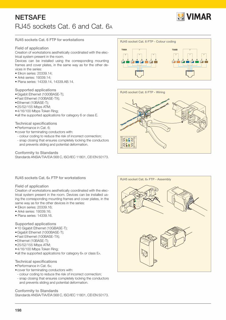
198
NETSAFERJ45 sockets Cat. 6 and Cat. 6A
RJ45 sockets Cat. 6 FTP for workstations
Field of applicationCreation of workstations aesthetically coordinated with the elec-trical system present in the room.Devices can be installed using the corresponding mounting frames and cover plates, in the same way as for the other de-vices in the series:• Eikon series: 20339.14;• Arké series: 19339.14;• Plana series: 14339.14, 14339.AB.14.
Supported applications• Gigabit Ethernet (1000BASE-T);• Fast Ethernet (100BASE-TX);• Ethernet (10BASE-T);• 25/52/155 Mbps ATM;• 4/16/100 Mbps Token Ring;• all the supported applications for category 6 or class E.
Technical specifications • Performance in Cat. 6;• cover for terminating conductors with:
- colour coding to reduce the risk of incorrect connection;- snap closing that ensures completely locking the conductors
and prevents sliding and potential deformation.
Conformity to StandardsStandards ANSIA/TIA/EIA 568 C, ISO/IEC 11801, CEI EN 50173.
RJ45 sockets Cat. 6A FTP for workstations
Field of applicationCreation of workstations aesthetically coordinated with the elec-trical system present in the room. Devices can be installed us-ing the corresponding mounting frames and cover plates, in the same way as for the other devices in the series:• Eikon series: 20339.16;• Arké series: 19339.16;• Plana series: 14339.16.
Supported applications• 10 Gigabit Ethernet (10GBASE-T);• Gigabit Ethernet (1000BASE-T);• Fast Ethernet (100BASE-TX);• Ethernet (10BASE-T);• 25/52/155 Mbps ATM;• 4/16/100 Mbps Token Ring;• all the supported applications for category 6A or class EA.
Technical specifications • Performance in Cat. 6A;• cover for terminating conductors with:
- colour coding to reduce the risk of incorrect connection;- snap closing that ensures completely locking the conductors
and prevents sliding and potential deformation.
Conformity to StandardsStandards ANSIA/TIA/EIA 568 C, ISO/IEC 11801, CEI EN 50173.
1 2 3 4 5 6 7 8
3a 4a1a
2a
1 2 3 4 5 6 7 8
2a 4a1a
3aT568A T568B
AB
87
A ABB2
1
63
45
BA
C AT. 5 e
RJ45 socket Cat. 6 FTP - Colour coding
1 2 3 4 5 6 7 8
3a 4a1a
2a
1 2 3 4 5 6 7 8
2a 4a1a
3aT568A T568B
AB
87
A ABB2
1
63
45
BA
C AT. 5 e
1 2 3 4 5 6 7 8
3a 4a1a
2a
1 2 3 4 5 6 7 8
2a 4a1a
3aT568A T568B
AB
87
A ABB2
1
63
45
BA
C AT. 5 e
RJ45 socket Cat. 6A FTP - Assembly
RJ45 socket Cat. 6 FTP - Wiring

199
NETSAFE
NE
TSA
FE
RJ45 sockets Cat. 6 and Cat. 6A
39,8
30,3 22,3
49
40
29,8
49
22,3
ARKÉ
PLANA 39,8
29,3 22,3
49
20339.14.NNext
19339.14.Bwhite
14339.14.SLSilver
20339.14.Bwhite
19339.14grey
14339.1414339.AB.14
white
20339.14grey
RJ45 socket Netsafe Cat. 6 FTPRJ45 socket with Netsafe connector Cat. 6, shielded, T568A/B universal wiring, 8 contacts, insulation-piercing terminals without using tools
39,8
30,3 22,3
49
40
29,8 22,3
49
ARKÉ
PLANA 39,8
29,3 22,3
49
20339.16.NNext
19339.16.Bwhite
14339.16.SLSilver
20339.16.Bwhite
19339.16grey
14339.16white
20339.16grey
RJ45 socket Netsafe Cat. 6A FTPRJ45 socket with Netsafe connector Cat. 6A, shielded, T568A/B universal wiring, 8 contacts, insulation-piercing terminals without using tools
The drawings of the side views give the overall dimensions and the flush depth in mmCables, from p. 200 - Patch panels, from p. 204
EIKON
EIKON
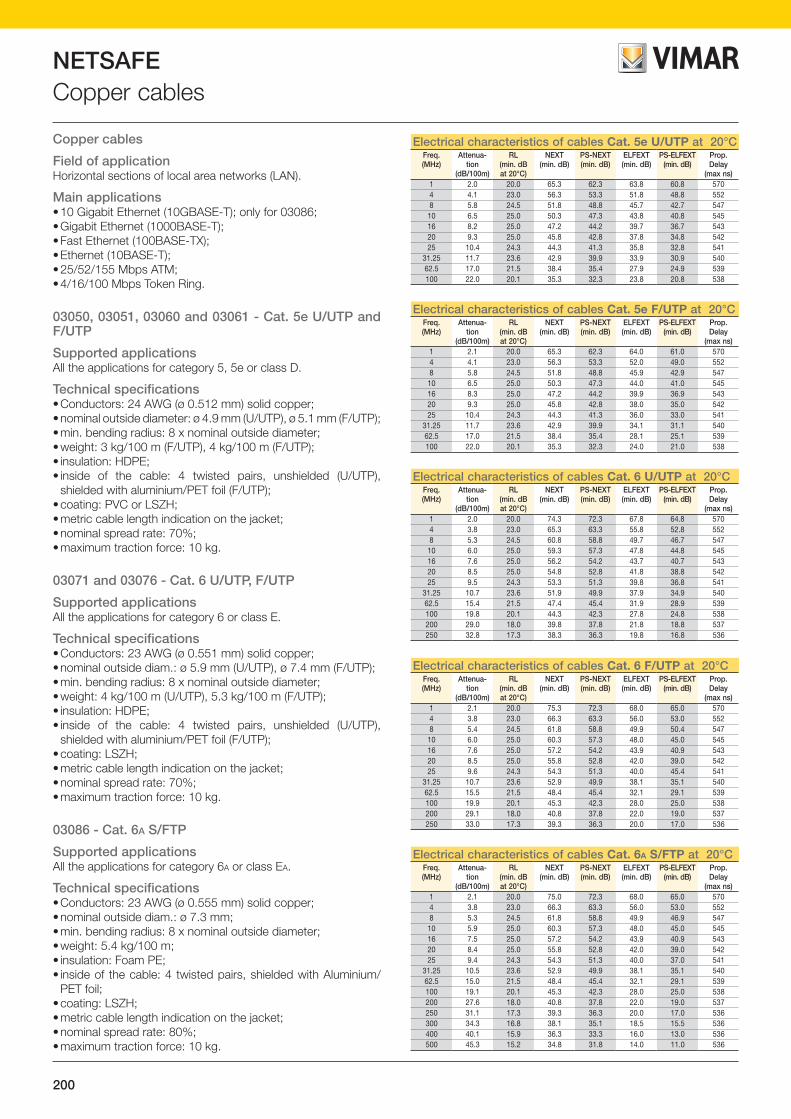
200
NETSAFECopper cables
Copper cables
Field of applicationHorizontal sections of local area networks (LAN).
Main applications• 10 Gigabit Ethernet (10GBASE-T); only for 03086;• Gigabit Ethernet (1000BASE-T);• Fast Ethernet (100BASE-TX);• Ethernet (10BASE-T);• 25/52/155 Mbps ATM;• 4/16/100 Mbps Token Ring.
03050, 03051, 03060 and 03061 - Cat. 5e U/UTP and F/UTP
Supported applicationsAll the applications for category 5, 5e or class D.
Technical specifications• Conductors: 24 AWG (ø 0.512 mm) solid copper;• nominal outside diameter: ø 4.9 mm (U/UTP), ø 5.1 mm (F/UTP);• min. bending radius: 8 x nominal outside diameter;• weight: 3 kg/100 m (F/UTP), 4 kg/100 m (F/UTP);• insulation: HDPE;• inside of the cable: 4 twisted pairs, unshielded (U/UTP),
shielded with aluminium/PET foil (F/UTP);• coating: PVC or LSZH;• metric cable length indication on the jacket; • nominal spread rate: 70%;• maximum traction force: 10 kg.
03071 and 03076 - Cat. 6 U/UTP, F/UTP
Supported applicationsAll the applications for category 6 or class E.
Technical specifications• Conductors: 23 AWG (ø 0.551 mm) solid copper;• nominal outside diam.: ø 5.9 mm (U/UTP), ø 7.4 mm (F/UTP);• min. bending radius: 8 x nominal outside diameter;• weight: 4 kg/100 m (U/UTP), 5.3 kg/100 m (F/UTP);• insulation: HDPE;• inside of the cable: 4 twisted pairs, unshielded (U/UTP),
shielded with aluminium/PET foil (F/UTP);• coating: LSZH;• metric cable length indication on the jacket; • nominal spread rate: 70%;• maximum traction force: 10 kg.
03086 - Cat. 6A S/FTP
Supported applicationsAll the applications for category 6A or class EA.
Technical specifications• Conductors: 23 AWG (ø 0.555 mm) solid copper;• nominal outside diam.: ø 7.3 mm;• min. bending radius: 8 x nominal outside diameter;• weight: 5.4 kg/100 m;• insulation: Foam PE;• inside of the cable: 4 twisted pairs, shielded with Aluminium/
PET foil;• coating: LSZH;• metric cable length indication on the jacket; • nominal spread rate: 80%;• maximum traction force: 10 kg.
Electrical characteristics of cables Cat. 5e U/UTP at 20°C Freq.(MHz)
Attenua-tion
(dB/100m)
RL(min. dBat 20°C)
NEXT(min. dB)
PS-NEXT(min. dB)
ELFEXT(min. dB)
PS-ELFEXT(min. dB)
Prop. Delay
(max ns)1 2.0 20.0 65.3 62.3 63.8 60.8 5704 4.1 23.0 56.3 53.3 51.8 48.8 5528 5.8 24.5 51.8 48.8 45.7 42.7 54710 6.5 25.0 50.3 47.3 43.8 40.8 54516 8.2 25.0 47.2 44.2 39.7 36.7 54320 9.3 25.0 45.8 42.8 37.8 34.8 54225 10.4 24.3 44.3 41.3 35.8 32.8 541
31.25 11.7 23.6 42.9 39.9 33.9 30.9 54062.5 17.0 21.5 38.4 35.4 27.9 24.9 539100 22.0 20.1 35.3 32.3 23.8 20.8 538
Electrical characteristics of cables Cat. 6 U/UTP at 20°C Freq.(MHz)
Attenua-tion
(dB/100m)
RL(min. dBat 20°C)
NEXT(min. dB)
PS-NEXT(min. dB)
ELFEXT(min. dB)
PS-ELFEXT(min. dB)
Prop. Delay
(max ns)1 2.0 20.0 74.3 72.3 67.8 64.8 5704 3.8 23.0 65.3 63.3 55.8 52.8 5528 5.3 24.5 60.8 58.8 49.7 46.7 54710 6.0 25.0 59.3 57.3 47.8 44.8 54516 7.6 25.0 56.2 54.2 43.7 40.7 54320 8.5 25.0 54.8 52.8 41.8 38.8 54225 9.5 24.3 53.3 51.3 39.8 36.8 541
31.25 10.7 23.6 51.9 49.9 37.9 34.9 54062.5 15.4 21.5 47.4 45.4 31.9 28.9 539100 19.8 20.1 44.3 42.3 27.8 24.8 538200 29.0 18.0 39.8 37.8 21.8 18.8 537250 32.8 17.3 38.3 36.3 19.8 16.8 536
Electrical characteristics of cables Cat. 6A S/FTP at 20°C Freq.(MHz)
Attenua-tion
(dB/100m)
RL(min. dBat 20°C)
NEXT(min. dB)
PS-NEXT(min. dB)
ELFEXT(min. dB)
PS-ELFEXT(min. dB)
Prop. Delay
(max ns)1 2.1 20.0 75.0 72.3 68.0 65.0 5704 3.8 23.0 66.3 63.3 56.0 53.0 5528 5.3 24.5 61.8 58.8 49.9 46.9 54710 5.9 25.0 60.3 57.3 48.0 45.0 54516 7.5 25.0 57.2 54.2 43.9 40.9 54320 8.4 25.0 55.8 52.8 42.0 39.0 54225 9.4 24.3 54.3 51.3 40.0 37.0 541
31.25 10.5 23.6 52.9 49.9 38.1 35.1 54062.5 15.0 21.5 48.4 45.4 32.1 29.1 539100 19.1 20.1 45.3 42.3 28.0 25.0 538200 27.6 18.0 40.8 37.8 22.0 19.0 537250 31.1 17.3 39.3 36.3 20.0 17.0 536300 34.3 16.8 38.1 35.1 18.5 15.5 536400 40.1 15.9 36.3 33.3 16.0 13.0 536500 45.3 15.2 34.8 31.8 14.0 11.0 536
Electrical characteristics of cables Cat. 6 F/UTP at 20°C Freq.(MHz)
Attenua-tion
(dB/100m)
RL(min. dBat 20°C)
NEXT(min. dB)
PS-NEXT(min. dB)
ELFEXT(min. dB)
PS-ELFEXT(min. dB)
Prop. Delay
(max ns)1 2.1 20.0 75.3 72.3 68.0 65.0 5704 3.8 23.0 66.3 63.3 56.0 53.0 5528 5.4 24.5 61.8 58.8 49.9 50.4 54710 6.0 25.0 60.3 57.3 48.0 45.0 54516 7.6 25.0 57.2 54.2 43.9 40.9 54320 8.5 25.0 55.8 52.8 42.0 39.0 54225 9.6 24.3 54.3 51.3 40.0 45.4 541
31.25 10.7 23.6 52.9 49.9 38.1 35.1 54062.5 15.5 21.5 48.4 45.4 32.1 29.1 539100 19.9 20.1 45.3 42.3 28.0 25.0 538200 29.1 18.0 40.8 37.8 22.0 19.0 537250 33.0 17.3 39.3 36.3 20.0 17.0 536
Electrical characteristics of cables Cat. 5e F/UTP at 20°C Freq.(MHz)
Attenua-tion
(dB/100m)
RL(min. dBat 20°C)
NEXT(min. dB)
PS-NEXT(min. dB)
ELFEXT(min. dB)
PS-ELFEXT(min. dB)
Prop. Delay
(max ns)1 2.1 20.0 65.3 62.3 64.0 61.0 5704 4.1 23.0 56.3 53.3 52.0 49.0 5528 5.8 24.5 51.8 48.8 45.9 42.9 54710 6.5 25.0 50.3 47.3 44.0 41.0 54516 8.3 25.0 47.2 44.2 39.9 36.9 54320 9.3 25.0 45.8 42.8 38.0 35.0 54225 10.4 24.3 44.3 41.3 36.0 33.0 541
31.25 11.7 23.6 42.9 39.9 34.1 31.1 54062.5 17.0 21.5 38.4 35.4 28.1 25.1 539100 22.0 20.1 35.3 32.3 24.0 21.0 538

201
NETSAFE
NE
TSA
FE
Copper cables
0305003050.B 03051
03060 03061
Cables category 5e U/UTP03050 Cable Cat. 5e, unshielded U/UTP, 4-pair, 24 AWG with PVC jacket, grey - 305 m03050.B As above - 1000 m03051 Cable Cat. 5e, unshielded U/UTP, 4-pair, 24 AWG with LSZH jacket, grey - 305 m
Cables category 5e F/UTP03060 Cable Cat. 5e, shielded F/UTP, 4-pair, 24 AWG with PVC jacket, grey - 305 m03061 Cable Cat. 5e, shielded F/UTP, 4-pair, 24 AWG with LSZH jacket, grey - 305 m
03071
Cables category 6 U/UTP03071 Cable Cat. 6, unshielded U/UTP, 4-pair, 23 AWG with LSZH jacket, green - 305 m
03076
Cables category 6 F/UTP03076 Cable Cat. 6, shielded F/UTP, 4-pair, 23 AWG with LSZH jacket, green - 500 m
03086
Cables category 6A S/FTP03086 Cable Cat. 6A, shielded S/FTP, 4-pair, 23 AWG with LSZH jacket, orange - 500 m
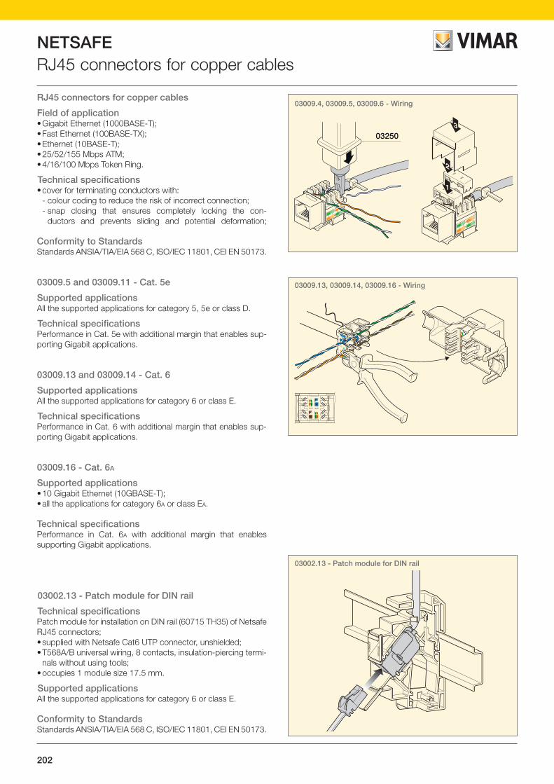
202
NETSAFERJ45 connectors for copper cables
03002.13 - Patch module for DIN rail
RJ45 connectors for copper cables
Field of application• Gigabit Ethernet (1000BASE-T);• Fast Ethernet (100BASE-TX);• Ethernet (10BASE-T);• 25/52/155 Mbps ATM;• 4/16/100 Mbps Token Ring.
Technical specifications• cover for terminating conductors with:
- colour coding to reduce the risk of incorrect connection;- snap closing that ensures completely locking the con-
ductors and prevents sliding and potential deformation;
Conformity to StandardsStandards ANSIA/TIA/EIA 568 C, ISO/IEC 11801, CEI EN 50173.
03009.5 and 03009.11 - Cat. 5e
Supported applicationsAll the supported applications for category 5, 5e or class D.
Technical specificationsPerformance in Cat. 5e with additional margin that enables sup-porting Gigabit applications.
03009.13 and 03009.14 - Cat. 6
Supported applicationsAll the supported applications for category 6 or class E.
Technical specificationsPerformance in Cat. 6 with additional margin that enables sup-porting Gigabit applications.
03009.16 - Cat. 6A
Supported applications• 10 Gigabit Ethernet (10GBASE-T);• all the applications for category 6A or class EA.
Technical specificationsPerformance in Cat. 6A with additional margin that enables supporting Gigabit applications.
03002.13 - Patch module for DIN rail
Technical specifications Patch module for installation on DIN rail (60715 TH35) of Netsafe RJ45 connectors;• supplied with Netsafe Cat6 UTP connector, unshielded;• T568A/B universal wiring, 8 contacts, insulation-piercing termi-
nals without using tools;• occupies 1 module size 17.5 mm.
Supported applicationsAll the supported applications for category 6 or class E.
Conformity to StandardsStandards ANSIA/TIA/EIA 568 C, ISO/IEC 11801, CEI EN 50173.
2
36
1
A
B
3
03250
1
2
36
1
A
B
2
3
03009.4, 03009.5, 03009.6 - Wiring
1 2 3 4 5 6 7 8
3a 4a1a
2a
1 2 3 4 5 6 7 8
2a 4a1a
3aT568A T568B
AB
87
A ABB2
1
63
45
BA
C AT. 5 e
03009.13, 03009.14, 03009.16 - Wiring

203
NETSAFE
NE
TSA
FE
RJ45 connectors for copper cables
∆ 03009.5 03009.11
RJ45 connectors Cat. 5e for patch panels∆ 03009.5 RJ45 connector Cat. 5e, shielded, for patch panel 03024.E and 03303.E, T568A/B universal wiring, 8 contacts, insulation-piercing
terminals 110 compatible03009.11 RJ45 connector Cat. 5e, unshielded, for patch panel 03024.E and 03303.E, T568A/B universal wiring, 8 contacts, insulation-piercing
terminals without using tools
Surface mounting cabinets and enclosures, from page 212 - Accessories, page 216
03009.13 03009.14
RJ45 connectors Cat. 6 for patch panels03009.13 RJ45 connector Cat. 6, unshielded, for patch panel 03024.E and 03303.E, T568A/B universal wiring, 8 contacts, insulation-piercing
terminals without using tools03009.14 RJ45 connector Cat. 6, shielded, for patch panel 03024.E and 03303.E, T568A/B universal wiring, 8 contacts, insulation-piercing
terminals without using tools
03009.16
RJ45 connectors Cat. 6A for patch panels03009.16 RJ45 connector Cat. 6A, shielded, for patch panel 03024.E and 03303.E, T568A/B universal wiring, 8 contacts, insulation-piercing
terminals without using tools
03002.13
Patch module for DIN rail (60715 TH35)03002.13 Permutation module for installation on DIN guide (60715 TH35) of Netsafe RJ45 connectors, occupying 1 x 17.5 mm module. Supplied
with Netsafe Cat6 UTP connector, unshielded, T568A/B universal wiring, 8 contacts, insulation-piercing terminals without using tools
59
54 17,5
9191
∆ Available until stocks last

204
NETSAFEPatch panels
Patch panels
Field of applicationHorizontal distribution or termination of devices in surface mounting cabinets and enclosures for data transmission. The system made with shielded components can ensure greater protection against interference of an electromagnetic nature present in the room.
Supported applications• 10 Gigabit Ethernet (10GBASE-T); only for 03024.9;• Gigabit Ethernet (1000BASE-T);• Fast Ethernet (100BASE-TX);• Ethernet (10BASE-T);• 25/52/155 Mbps ATM;• 4/16/100 Mbps Token Ring.
Conformity to StandardsStandards ANSIA/TIA/EIA 568 C, ISO/IEC 11801, CEI EN 50173.
03024.E - Technical specifications• Ideal for 19” surface mounting cabinets and enclosures;• configurable to measure using RJ45 connectors 03008.9,
03009.5;• capacity to install up to 16 socket outlets;
03024.3 - Technical specifications• 50 RJ45 connectors Cat. 3, T568A/B universal wiring;• front panel ready for port identification;• insulation-piercing terminals 110 compatible.
03024.4 - Technical specifications• 24 unshielded RJ45 connectors Cat. 5e, T568A/B universal
wiring;• front panel ready for port identification;• cable holder (included) to simplify the wiring;• insulation-piercing terminals 110 compatible.
03024.5 - Technical specifications• 24 shielded RJ45 connectors Cat. 5e shielded, T568 A/B uni-
versal wiring;• front panel ready for port identification; • cable holder (included) to simplify the wiring;• insulation-piercing terminals 110 compatible.
03024.6 - Technical specifications• 24 unshielded RJ45 connectors Cat. 6, T568A/B universal
wiring;• front panel ready for port identification;• cable holder (included) to simplify the wiring;• insulation-piercing terminals 110 compatible.
03024.7 - Technical specifications• 24 shielded RJ45 connectors Cat. 6, T568A/B universal wiring;• front panel ready for port identification;• cable holder (included) to simplify the wiring;• dust flaps;• insulation-piercing terminals 110 compatible.
03024.9 - Technical specifications• 24 shielded RJ45 connectors Cat. 6A, T568A/B universal wiring;• front panel ready for port identification;• cable holder (included) to simplify the wiring.
482 mm - 19”
60 mm
44,4
mm
1 un
ità
rack
03024.E
105 mm
480 mm - 19”
44,5
mm
1 un
ità r
ack
03024.3
153 mm480 mm - 19”
44,5
mm
1 un
ità r
ack
03024.4
110 mm
480 mm - 19”
44,5
mm
1 un
ità r
ack
03024.5
153 mm
480 mm - 19”
44,5
mm
1 un
ità r
ack
03024.6
104,8 mm
482,6 mm - 19”
44 m
m1
unità
rac
k
12
34
56
78
910
1112
1314
1516
1718
1920
2122
2324
12
34
56
78
910
1112
1314
1516
1718
1920
2122
2324
03024.7
92,7 mm
482,6 mm - 19”
44 m
m1
unità
rac
k
2
1
2
1
4
3
6
5
8
7
10
9
12
11
14
13
16
15
18
17
20
19
22
21
24
23
CAT.6A
7
8
9
10
11
12
13
14
15
16
17
18
19
20
21
22
23
24
2
3
4
5
6
1
03024.9

205
NETSAFE
NE
TSA
FE
Patch panels
03024.E
Patch panel with empty ports03024.E 19 in patch panel with 16 empty ports - 1 rack unit. To be completed with RJ45 connectors 03008.9 or 03009
03024.3
Patch panel Cat. 3, complete with RJ45 connectors for surface mounting cabinets and enclosures03024.3 19” patch panel complete with 50 RJ45 connectors for telephony, insulation-piercing terminals 110 compatible - 1 rack unit
03024.503024.4
Patch panel Cat. 5e, complete with RJ45 connectors for surface mounting cabinets and enclosures03024.4 19” patch panel complete with 24 RJ45 connectors Cat. 5e, unshielded, T568A/B universal wiring, 8 contacts, insulation-piercing terminals
110 compatible - 1 rack unit03024.5 19” patch panel complete with 24 RJ45 connectors Cat. 5e, shielded, T568A/B universal wiring, 8 contacts, insulation-piercing terminals
110 compatible - 1 rack unit
Patch panel Cat. 6, complete with RJ45 connectors for surface mounting cabinets and enclosures03024.6 19” patch panel complete with 24 RJ45 connectors Cat. 6, unshielded, T568A/B universal wiring, 8 contacts, insulation-piercing terminals
110 compatible - 1 rack unit03024.7 19” patch panel complete with 24 RJ45 connectors Cat. 6, shielded, T568A/B universal wiring, 8 contacts, insulation-piercing terminals
110 compatible - 1 rack unit
03024.6 03024.7
Patch panel Cat. 6A, complete with RJ45 connectors for surface mounting cabinets and enclosures03024.9 19” patch panel complete with 24 RJ45 connectors Cat. 6A, shielded, T568A/B universal wiring, 8 contacts, insulation-piercing terminals
without using tools - 1 rack unit
03024.9
Surface mounting cabinets and enclosures, from page 212 - Accessories, page 216

206
NETSAFEPatch cords
Patch cords Cat. 5e U/UTP, F/UTP in copper
Field of applicationConnection between the ports of the communication devices and a modular patch panel system.
Supported applications• Gigabit Ethernet (1000BASE-T);• Fast Ethernet (100BASE-TX);• Ethernet (10BASE-T);• 25/52/155 Mbps ATM;• 4/16/100 Mbps Token Ring;• all the other supported applications for category 5, 5e or class D.
Conformity to StandardsStandards ANSIA/TIA/EIA 568 C, ISO/IEC 11801, CEI EN 50173.
Patch cords Cat. 6 U/UTP
Field of applicationConnection between the ports of the communication devices and a modular patch panel system.
Supported applications• Gigabit Ethernet (1000BASE-T);• Fast Ethernet (100BASE-TX);• Ethernet (10BASE-T);• 25/52/155 Mbps ATM;• 4/16/100 Mbps Token Ring;• all the other supported applications for category 6 or class E.
Conformity to StandardsStandards ANSIA/TIA/EIA 568 C, ISO/IEC 11801, CEI EN 50173.
Patch cords Cat. 6 S/FTP in copper
Field of applicationConnection between the ports of the communication devices and a modular patch panel system.
Supported applications• Gigabit Ethernet (1000BASE-T);• Fast Ethernet (100BASE-TX);• Ethernet (10BASE-T);• 25/52/155 Mbps ATM;• 4/16/100 Mbps Token Ring;• all the other supported applications for category 6 or class E.
Conformity to StandardsStandards ANSIA/TIA/EIA 568 C, ISO/IEC 11801, CEI EN 50173.
Patch cords Cat. 6A S/FTP in copper
Field of applicationConnection between the ports of the communication devices and a modular patch panel system.
Supported applications• 10 Gigabit Ethernet (10GBASE-T);• Gigabit Ethernet (1000BASE-T);• Fast Ethernet (100BASE-TX);• Ethernet (10BASE-T);• 25/52/155 Mbps ATM;• 4/16/100 Mbps Token Ring;• all the other supported applications for category 6A or class EA.
Conformity to StandardsStandards ANSIA/TIA/EIA 568 C, ISO/IEC 11801, CEI EN 50173.

207
NETSAFE
NE
TSA
FE
Patch cords
03017.1
03018.1
03019.02
Patch cords Cat. 5e U/UTP in copper03017.05 RJ45 patch cord Cat. 5e, unshielded U/UTP cable with 4 pairs 24 AWG, PVC jacket, grey - 0.5 m03017.1 As above - 1 m03017.2 As above - 2 m03017.3 As above - 3 m03017.5 As above - 5 m
Patch cords Cat. 5e F/UTP in copper03018.1 RJ45 patch cord Cat. 5e, shielded F/UTP cable with 4 pairs 26 AWG, PVC jacket, white - 1 m03018.2 As above - 2 m03018.3 As above - 3 m03018.5 As above - 5 m
Patch cords Cat. 6 U/UTP in copper03019.1 RJ45 patch cord Cat. 6, unshielded U/UTP cable with 4 pairs 24 AWG, PVC jacket, blue - 1 m03019.2 As above - 2 m03019.3 As above - 3 m03019.5 As above - 5 m03019.02 RJ45 flat patch cord Cat. 6, unshielded U/UTP with 4 pairs 30 AWG, PVC jacket, grey - 20 cm
RJ45 connectors for patch panels, from page 202 - Patch panels, from page 204
Patch cords Cat. 6 S/FTP in copper03020.1 RJ45 patch cord Cat. 6, shielded S/FTP with 4 pairs 26 AWG, PVC jacket, blue - 1 m03020.2 As above - 2 m03020.3 As above - 3 m03020.5 As above - 5 m
03020.1
Patch cords Cat. 6A S/FTP in copper03022.1 RJ45 patch cord Cat. 6A, shielded S/FTP with 4 pairs 26 AWG, PVC jacket, orange - 1 m03022.2 As above - 2 m03022.3 As above - 3 m03022.5 As above - 5 m
03022.1
03019.1

208
NETSAFEFibre-optic cables and patch cords
Fibre-optic cables
Field of applicationConstruction of horizontal and vertical connections both inside and outside.
Supported applications• 10GBASE-LX4;• 1000BASE-SX and LX;• 100BASE-FX;• 10BASE;• FOIRL;• FDDI PDM;• fibre channel (FC-PH) at 133/266/531/1062 Mbps• 52/155/1200 Mbps ATM;• 4/16 Mbps Token Ring;• all the other supported applications for category OM2.
Technical specifications• Internal or external use;• loose multimode cables 50/125 µm;• cables in category OM2;• 4 or 8 fibres;• anti-rodent protection in fibreglass;• external coating: LSZH;• available in coils of 500 or 2000 m, with the possibility of cutting
to size (minimum 100 m).
For information on cutting to size, please contact our Sales Network.
Conformity to StandardsStandards ANSIA/TIA/EIA 568 C, ISO/IEC 11801, CEI EN 50173.
Mechanical characteristics
Number of fibres Diameter mm2Minimum install-
able radius of curvature (mm)
Weight (kg/km) Maximum installa-tion strain (N)
4/8 6.4 140 48 1,250
Optical characteristics and performance
Passband(MHz x km)
Maximum link lengthfor 1 Gbit/s (m)
Maximum attenuation(dB/km)
850 nm 1300 nm 850 nm 1300 nm 850 nm 1300 nm
500 500 550 550 2.4 0.6
Fibre optic patch cords
Field of application• internal use (ambient category 1) for:
- connection to work station;- devices for communications rooms;- connection to electronic devices;- cross connection.
Technical specifications• Factory terminated and tested to industry standards to ensure
reliability and safety;• High quality ceramic ferrule: ensures low insertion loss.
Conformity to StandardsANSIA/TIA/EIA 568 C, ISO/IEC 11801, CEI EN 50173;Bellcore GR-326-SET generic requirements; IEC 60874 standards for connectors for fibre optic cables.
Max loss, after the 0.75 dB test Type of test Condition
Low temperature (FOTP-188) -10 °C, 4 days
Life test (FOTP-4) 60 °C, 4 days
Humidity (FOTP-5) 90 - 95°C at 40°C
Impact (FOTP-2) 8 falls from 1.5 m
Strength of coupling mechanism (FOTP-185) 33 N at 0° for 5 s
Durability (FOTP-21) 500 cycles
Cable retention (FOTP-6) 90 N at 0° for 5 s
Flexibility (FOTP-1) 0.5 kg at 25 cm, from +90° to -90°, 100 cycles
Twist (FOTP-36) 15 N at 0°. 5 twists, 10 cycles

209
NETSAFE
NE
TSA
FE
Fibre-optic cables and patch cords
Fibre-optic cables03150.1 Loose multimode fibre optic cable 50/125 µm with 4 fibres, with LSZH jacket - 500 m coil03150.2 Loose multimode fibre optic cable 50/125 µm with 4 fibres, with LSZH jacket - 2000 m coil03151.1 Loose multimode fibre optic cable 50/125 µm with 8 fibres, with LSZH jacket - 500 m coil03151.2 Loose multimode fibre optic cable 50/125 µm with 8 fibres, with LSZH jacket - 2000 m coil
Fibre optic trays, optical adaptors and connectors, from page 206
03150.103150.2
03151.103151.2
03110.SC
Fibre optic patch cords 62.5 µm 03110.SC SC patch cord, multimode fibre optic cable 62.5/125 µm duplex - 2 m
03111.SC
Fibre optic patch cords 50 µm 03111.SC SC patch cord, multimode fibre optic cable 50/125 µm duplex - 2 m
03111.LC 03111.SC.LC
Fibre optic patch cords 50 µm 03111.LC LC patch cord, multimode fibre optic cable 50/125 µm duplex - 2 m03111.SC.LC SC/LC patch cord, multimode fibre optic cable 50/125 µm duplex - 2 m

210
NETSAFEFibre optic trays, optical adaptors and connectors
Fibre optic trays
Field of application• Racks or cabinets (19”);• Backbone terminations in telecommunications cabinets or in
the main distribution rooms.
Technical specifications• Low profile design: only takes up the space of one rack unit
(1.75 "-1U);• front panel that slides out to facilitate connecting the optical
fibre, even with the fibre optic tray installed on the rack;• depth-adjustable to ensure the minimum radius of curvature for
the fibre;• ready for ST optical adaptors: - 03124.ST.E - max. 24 connectors; • ready for SC and LC optical adaptors: - 03124.SC.E - max. 24 connectors; • with accessories for fibre management inside the tray.
Conformity to StandardsStandards ANSIA/TIA/EIA 568 C, ISO/IEC 11801, CEI EN 50173.
435 mm
222 mm
484 mm - 19”
44,4
mm
1 un
ità
rack
435 mm222 mm
484 mm - 19”
44,4
mm
1 un
ità
rack
03124.ST.E
03124.SC.E
Connectors for fibre-optic cables
Field of application• Patch panels;• Splitters;• Terminations to the devices;• Cable joints and/or repairs.
Technical specifications• No polishing required;• Does not use epoxy resins and the associated crystallization
oven;• Does not require electrical equipment;• Pre-connected ceramic ferrule: ensures contact with the opti-
cal fibres, lengthens lifespan, provides high performance;• Interconnection compatibility: SC or ST connectors;• For fibres 50/125 mm or 62.5/125 mm;• Estimated time for assembly on site: - approximately 1 minute for 900 µm; - approximately 3 minutes for fibres with protective sheath;• Insertion loss 0.3 dB (typical);• Lifespan: <0.2 dB in change (500 cycles);• storage temperature: from -40°C to 65°C;• ultimate strength (tensile strength): 6.7.N;• ceramic ferrule;• reflection factor: -30 dB (typical).
Conformity to StandardsStandards ANSIA/TIA/EIA 568 C, ISO/IEC 11801, CEI EN 50173.
Corpo delconnettore
Cappuccio antipolvere
Manicotto a crimpare
Guaina di protezione
Adattatore per manicotto
Cappuccioantipolvere
03105.SC, 03106.SC
Antidust cover
Antidust cover
Connectorunit
Adapter for sleeve
Crimping sleeve
Sheath
03106.ST
Cappuccio antipolvere
Corpo del connettore
Cappuccio antipolvere
Alloggiamento posteriore
Guaina di protezione
Antidust cover
Antidust cover
Sheath
Connector unit

211
NETSAFE
NE
TSA
FE
Fibre optic trays, optical adaptors and connectors
03124.ST.E 03124.SC.E
03101.ST 03101.SC 03101.LC
Fibre optic trays03124.ST.E 19 in fibre optic tray ready for 24 optical adaptors for ST connectors, removable front panel - 1 rack unit03124.SC.E 19 in fibre optic tray ready for 24 optical adaptors for SC or LC connectors, removable front panel - 1 rack unit
Optical adaptors for fibre optic trays03101.ST ST optical adaptor for fibre optic trays 03124.ST.E03101.SC SC optical adaptor for fibre optic trays 03124.SC.E03101.LC LC optical adaptor for fibre optic trays 03124.SC.E
03105.SC
Connectors for fibre-optic cables03105.SC Connector for multimode fibre-optic cable 62.5/125 µm, type SC
03106.SC 03106.ST
Connectors for fibre-optic cables03106.SC Connector for multimode fibre-optic cable 50/125 µm, type SC03106.ST Connector for multimode fibre-optic cable 50/125 µm, type ST
Fibre-optic cables and patch cords, from page 208

212
NETSAFESurface mounting cabinets and accessories
420 mm600 mm
373
mm
420 mm600 mm
501
mm
420 mm600 mm
635
mm
420 mm600 mm
768
mm
100 mm
600 mm
501
mm
100 mm
600 mm
635
mm
100 mm
600 mm
768
mm
Surface mounting cabinets
Field of applicationDedicated metalwork for housing the active and passive com-ponents in local area networks.
Technical specifications• Colour: RAL 7035;• number and dimensions of cable inlet holes: 2 holes 20x6 cm,
one on the top and one on the bottom with guillotine;• possibility of hinge opening in 9, 12 and 15 rack unit versions,
by using the dedicated kit (equipped with unified key lock);• number of risers: 2 (adjustable in depth);• fitted for mounting 1 ventilation kit 03256;• transparent tempered glass doors, reversible, with locks;• locks with unified keys;• removable side panels;• fully removable;• protection class IP20.
Conformity to StandardsIEC 297-1- Distance between holes;EN 60529 - Protection class;UNI EN 12150-1: 2001 - Glass fragmentation test;UNI EN 1288-3 - Tempered glass.
03209.3
03206.3 03212.3
03215.3
03209.3L 03212.3L 03215.3L
Surface mounting cabinet 03209.3 with hinged opening kit 03209.3L

213
NETSAFE
NE
TSA
FE
Surface mounting cabinets and accessories
03206.3 03206.3P
03209.3 03209.3L
03212.3L03212.3
03215.3 03215.3L
Surface mounting cabinet 600x420x373 mm03206.3 Surface mounting cabinet for installation of 19 in panels up to 6 rack units, RAL 7035. Dimensions 600x420x373 mm; weight 16 kg03206.3P Spare door for enclosure 03206.3
Surface mounting cabinet 600x420x501 mm03209.3 Surface mounting cabinet for installation of 19" panels up to 6 rack units, RAL 7035. Dimensions 600x420x373 mm; weight 20 kg03209.3P Spare door for enclosure 03209.303209.3L Hinged opening kit for enclosure 03209.3; weight 8 kg
Surface mounting cabinet 600x420x635 mm03212.3 Surface mounting cabinet for installation of 19" panels up to 12 rack units, RAL 7035. Dimensions 600x420x635 mm; weight 23 kg03212.3P Spare door for enclosure 03212.303212.3L Hinged opening kit for enclosure 03212.3; weight 10 kg
Surface mounting cabinet 600x420x768 mm03215.3 Surface mounting cabinet for installation of 19" panels up to 15 rack units, RAL 7035. Dimensions 600x420x768 mm; weight 27 kg03215.3P Spare door for enclosure 03215.303215.3L Hinged opening kit for enclosure 03215.3; weight 11 kg
Patch panels, from page 204 - Fibre optic trays, from page 210
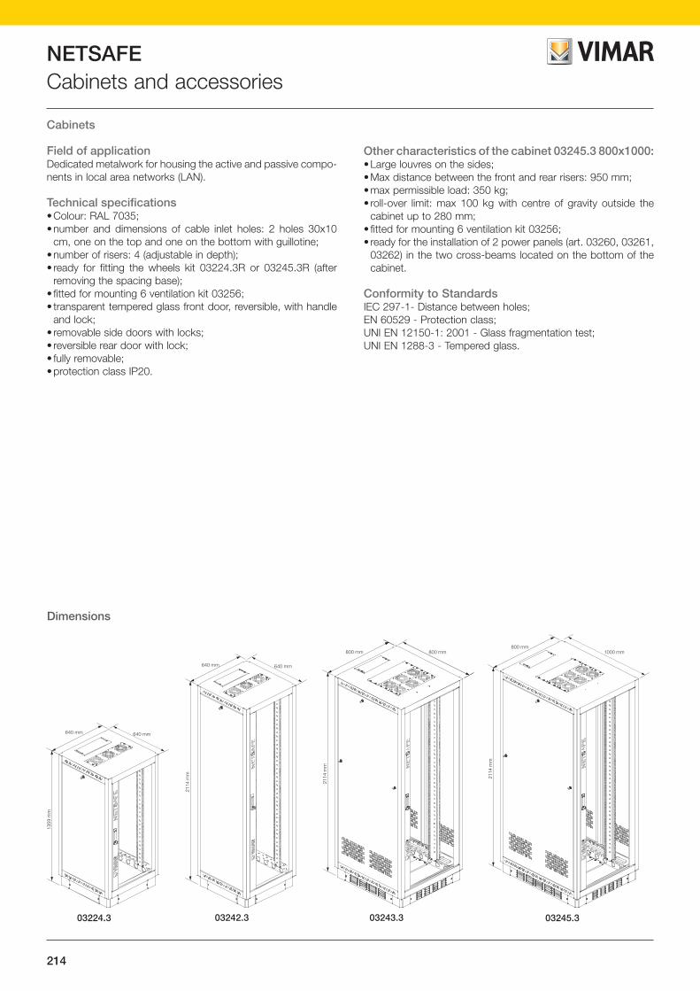
214
NETSAFECabinets and accessories
640 mm640 mm
2114
mm
2114
mm
800 mm800 mm 1000 mm800 mm
2114
mm
640 mm640 mm
1359
mm
Cabinets
Field of applicationDedicated metalwork for housing the active and passive compo-nents in local area networks (LAN).
Technical specifications• Colour: RAL 7035;• number and dimensions of cable inlet holes: 2 holes 30x10
cm, one on the top and one on the bottom with guillotine;• number of risers: 4 (adjustable in depth);• ready for fitting the wheels kit 03224.3R or 03245.3R (after
removing the spacing base);• fitted for mounting 6 ventilation kit 03256;• transparent tempered glass front door, reversible, with handle
and lock;• removable side doors with locks;• reversible rear door with lock;• fully removable;• protection class IP20.
Dimensions
Other characteristics of the cabinet 03245.3 800x1000:• Large louvres on the sides; • Max distance between the front and rear risers: 950 mm;• max permissible load: 350 kg;• roll-over limit: max 100 kg with centre of gravity outside the
cabinet up to 280 mm;• fitted for mounting 6 ventilation kit 03256;• ready for the installation of 2 power panels (art. 03260, 03261,
03262) in the two cross-beams located on the bottom of the cabinet.
Conformity to StandardsIEC 297-1- Distance between holes;EN 60529 - Protection class;UNI EN 12150-1: 2001 - Glass fragmentation test;UNI EN 1288-3 - Tempered glass.
03224.3 03242.3 03243.3 03245.3

215
NETSAFE
NE
TSA
FE
Cabinets and accessories
03224.3 03224.3P
03245.3 03245.3P
Cabinet 640x640x1359 mm and 640x640x2114 mm03224.3 Cabinet for installation of 19" panels up to 25 rack units, RAL 7035. Dimensions 640x640x1359 mm; weight 70 kg03224.3P Spare door for cabinet 03224.303242.3 Cabinet for installation of 19" panels up to 42 rack units, RAL 7035. Dimensions 640x640x2114 mm; weight 110 kg03242.3P Spare door for cabinet 03242.3
Cabinet 800x800x2114 mm and 800x1000x2114 mm03243.3 Cabinet for installation of 19" panels up to 42 rack units, RAL 7035. Dimensions 800x800x2114 mm; weight 130 kg03245.3 Cabinet for installation of 19" panels up to 42 rack units, RAL 7035. Dimensions 800x1000x2114 mm; weight 195 kg03245.3P Spare door for cabinets 03243.3 and 03245.3
03243.3
03242.3 03242.3P
Patch panels, from page 204 - Fibre optic trays, from page 210

216
NETSAFEAccessories for cabinets and enclosures
03204.1U
459,5 mm
482 mm - 19”
89 m
m2
unità
ra
ck
62 m
m
705 mm482 mm - 19”
89 m
m2
unità
ra
ck
03204.2U
19 mm
53 m
m
510 mm
03251
03204.1UM
Accessories for cabinets03204.2U Removable shelf, depth 450 mm - 2 rack units. Maximum permissible load 20 kg
03204.1U 19" fixed shelf, depth 700 mm - 2 rack units. Maximum permissible load 100 kg
Accessories for cabinets03251 Set of vertical cable guide rings for cabinets03204.1UM Telescopic rails for fixed shelf 03204.1U. Maximum permissible load 50 kg

217
NETSAFE
NE
TSA
FE
Accessories for cabinets and enclosures
03224.3R
03245.3R
03259.3
03258.3
Set of wheels for cabinets03224.3R Set of wheels for cabinets 03224.3, 03242.3 and 03243.303245.3R Set of wheels for cabinets 03245.3
Spare accessories03258.3 Spare lock with 2 keys, made of metal for enclosures 03206.3, 03209.3, 03212.3 and 03215.303259.3 Spare handle with 2 keys, for cabinets 03224.3, 03242.3, 03243.3 and 03245.3
Cabinets, from page 214

218
NETSAFEAccessories for cabinets and enclosures
03255 - Contents of the Kit
Clamp for fixing termination tool
Microscope Crimping pliers Pliers for removing outer sheath
Fibre cutting tool Tweezers
Tool for terminating the connector
Waste container Marker pen Calibrated templates Manuals with instructions for terminating
Pliers for removing outer sheath on 125 fibres
Fibre optic tools and accessories kitThe set of tools and accessories for terminating Netsafe 03255 fibre optics contains all the necessary tools for fibre optic termination.Packaged in a handy carrying case, it also contains a CD/R for practice and the installation guide for SC and ST connectors.
Technical specifications• Fast fibre terminating;• fibre terminating directly on site;• terminating possible at any temperature;• no polishing required;• does not require using resins nor their oven for crystallization,
thus no toxic materials are handled and it is not necessary to issue any specific documentation.
482 mm - 19”
44,4
mm
1 un
ità
rack
250 mm
482 mm - 19”
89 m
m2
unità
ra
ck
380 mm
482 mm - 19”
89 m
m2
unità
ra
ck
482 mm - 19”
133,
3 m
m3
unità
rack
482 mm - 19”
60 mm
44,4
mm
1 un
itàra
ck
482 mm - 19”
89 m
m2
unità
rack
482 mm - 19”
89 m
m2
unità
rack
60 mm
482 mm - 19”
44,4
mm
1 un
itàra
ck
Dimensions
03200.1A
03201.1U
03200.2U
03201.2U 03201.3U
03202.2U 03203.2U
03200.1U

219
NETSAFE
NE
TSA
FE
Accessories for cabinets and enclosures
03200.2U03200.1U03200.1A
03201.3U03201.2U03201.1U
03256 03257 03202.2U
03250 03255
Accessories for surface mounting cabinets and enclosures03200.1A 19" panel with open cable outlet - 1 rack unit03200.1U 19" panel with cable outlet - 1 rack unit03200.2U 19" panel with cable outlet - 2 rack units
Accessories for surface mounting cabinets and enclosures03201.1U 19" blind panel - 1 rack unit03201.2U 19" blind panel - 2 rack units03201.3U 19" blind panel - 3 rack units
Accessories for surface mounting cabinets and enclosures03202.2U 19" mounting frame for live devices, depth 38 cm - 2 rack units03203.2U 19" mounting frame for live devices, depth 25 cm - 2 rack units03256 Fan 230 V~ 50-60 Hz for surface mounting cabinet and enclosures, complete with protective grille and power cable with plug 2P+E 16
A 250 V~ combined German and French standard 03257 Metal screw and cage nut for fixing 19" panels in the surface mounting cabinets and enclosures
Accessories for surface mounting cabinets and enclosures03250 Tool for terminating the twisted cable on insulation-piercing terminals type 11003255 Set of tools and accessories for installing connectors for SC and ST type fibre optic cables
Surface mounting cabinets and enclosures, from page 212
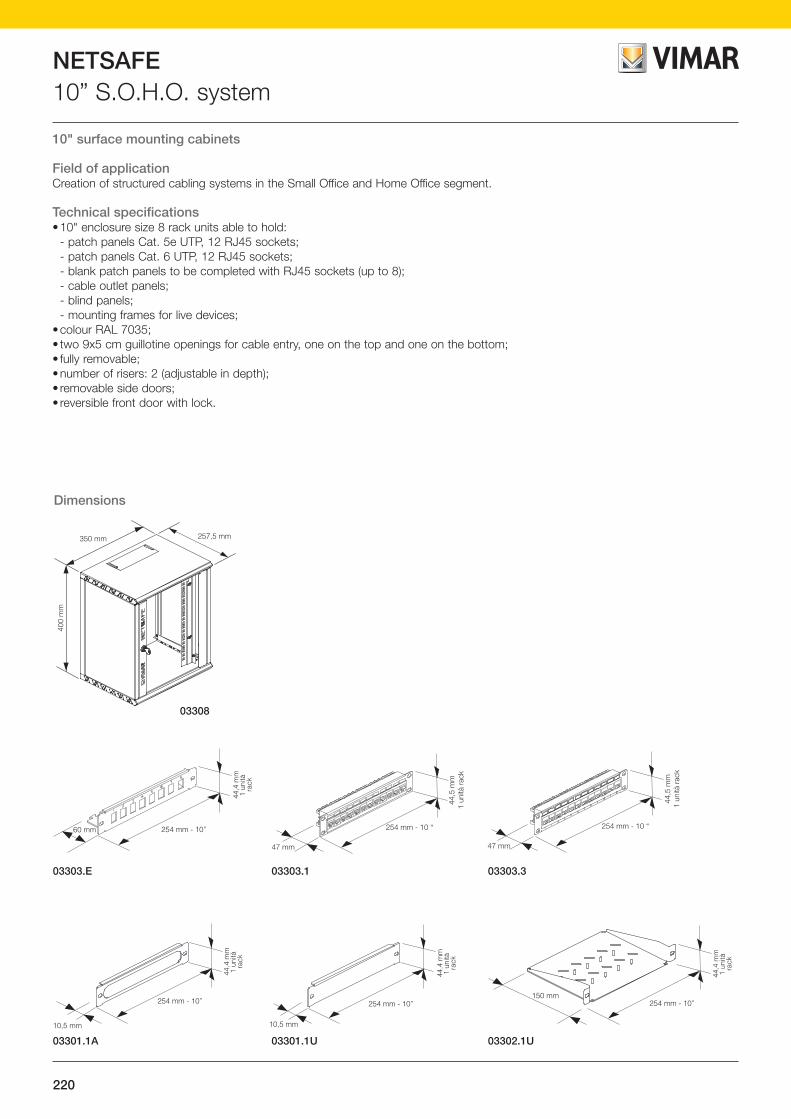
220
NETSAFE10” S.O.H.O. system
10" surface mounting cabinets
Field of applicationCreation of structured cabling systems in the Small Office and Home Office segment.
Technical specifications• 10" enclosure size 8 rack units able to hold: - patch panels Cat. 5e UTP, 12 RJ45 sockets; - patch panels Cat. 6 UTP, 12 RJ45 sockets; - blank patch panels to be completed with RJ45 sockets (up to 8); - cable outlet panels; - blind panels; - mounting frames for live devices;• colour RAL 7035;• two 9x5 cm guillotine openings for cable entry, one on the top and one on the bottom;• fully removable;• number of risers: 2 (adjustable in depth);• removable side doors;• reversible front door with lock.
Dimensions
257,5 mm350 mm
400
mm
03308
60 mm 254 mm - 10”
44,4
mm
1 un
ità
rack
254 mm - 10 “
47 mm
44,5
mm
1 un
ità r
ack
254 mm - 10 “
47 mm
44,5
mm
1 un
ità r
ack
03303.E 03303.303303.1
10,5 mm
254 mm - 10”
44,4
mm
1 un
ità
rack
150 mm254 mm - 10”
44,4
mm
1 un
ità
rack
10,5 mm
254 mm - 10”
44,4
mm
1 un
ità
rack
03301.1A 03302.1U03301.1U

221
NETSAFE
NE
TSA
FE
10” S.O.H.O. system
03308
03303.303303.103303.E
03301.1U03301.1A 03302.1U
10" surface mounting cabinet03308 Surface mounting cabinet for installation of 10" panels up to 8 rack units, RAL 7035.
Dimensions 350x258x400 mm; weight 8 kg
Patch panels03303.E 10" patch panel with 8 empty ports - 1 rack unit03303.1 10” patch panel complete with 12 RJ45 connectors Cat. 5e unshielded, T568A/B universal wiring, 8 contacts, insulation-piercing
terminals type 110 - 1 rack unit 03303.3 10” patch panel complete with 12 RJ45 connectors Cat. 6 unshielded, T568A/B universal wiring, 8 contacts, insulation-piercing
terminals type 110 - 1 rack unit
Accessories03301.1A 10" panel open cable outlet - 1 rack unit03301.1U 10" blind panel - 1 rack units03302.1U 10" mounting frame for live devices, depth 15 cm - 1 rack units

222
NETSAFEPower panels
Power panels
Field of applicationElectrical power socket outlets inside surface mounting cabinets and/or enclosures.
03260 - Technical specifications• 7 universal SICURY socket outlets 2P+E 16 A 250 V~ for:
- 2P 2.5 A Europlugs;- 2P and 2P+E Italian standard 10 A and 16 A 250 V~ plugs;- 2P+E 16 A 250 V~ German standard plugs;- 2P American standard flat pin 15 A 125 V~ non-polarised
plugs;• cable: 3 m 3G1.5 mm2 with 2P+E 16 A 250 V~ plug Italian
standard S17 (non-removable);• dimensions: 19” x 2 rack units.
Conformity to StandardsLV directive CEI 23-50 (IEC 60884-1).
03261 - Technical specifications• 6 universal SICURY socket outlets 2P+E 16 A 250 V~ for:
- 2P 2.5 A Europlugs;- 2P and 2P+E Italian standard 10 A and 16 A 250 V~ plugs;- 2P+E 16 A 250 V~ German standard plugs;- 2P American standard flat pin 15 A 125 V~ non-polarised
plugs;• cable: 3 m 3G1.5 mm2 with 2P+E 16 A 250 V~ plug Italian
standard S17 (non-removable);• 2P 16 AX 250 V~ switch;• pilot light with red diffuser for microtube lamp:
- 07052: neon lamp 250 V~ 0.5 W ø 6.3x28 mm, red;• dimensions: 19” x 2 rack units.
Conformity to StandardsLV directive CEI 23-50 (IEC 60884-1), EN 62094-1, EN 60669-1.
03262 - Technical specifications• 6 universal SICURY socket outlets 2P+E 16 A 250 V~ for:
- 2P 2.5 A Europlugs;- 2P and 2P+E Italian standard 10 A and 16 A 250 V~ plugs;- 2P+E 16 A 250 V~ German standard plugs;- 2P American standard flat pin 15 A 125 V~ non-polarised
plugs;• cable: 3 m 3G1.5 mm2 with 2P+E 16 A 250 V~ plug Italian
standard S17 (non-removable);• circuit breaker 1P+N C 16 120-230 V~ 50-60 Hz, p.i. 3000 A;• pilot light with red diffuser for microtube lamp:
- 07052: neon lamp 250 V~ 0.5 W ø 6.3x28 mm, red;• dimensions: 19” x 2 rack units.
Conformity to StandardsLV directive CEI 23-50 (IEC 60884-1), EN 62094-1, EN 60898-1.
Pilot light - replacing the lamp
1 1.1 1.2 1.5 2 2.5 3 4 5 6 7 8 9 10 11 12
MULTIPLI DELLA CORRENTE NOMINALE In
Zona di interventotermico a freddo
300
200
1008060
40
20
1086
4
2
1
40
20
1086
4
2
10,80,6
0,4
0,2
0,10,080,06
0,04
0,02
0,01
MIN
UT
IS
EC
ON
DI
Zona di interventoelettromagnetico
Circuit breakerCurrent-time tripping diagram
Thermal trippingarea with cold start
Electromagnetictripping area
MULTIPLES OF RATED CURRENT In
SE
CO
ND
SM
INU
TE
S

223
NETSAFE
NE
TSA
FE
Power panels
03262
03261
03260
Power panel03260 19" panel complete with:
• 7 SICURY outlets 2P+E 16 A 250 V~ universal, for Europlugs 2P 2.5 A, plugs 2P and 2P+E 10 A and 16 A Italian standard, plugs 2P+E 16 A 250 V~ German standard, plugs 2P 15 A 125 V~ American standard flat pin, non-polarised. Do not make the earth connection with
the 2P+E 16 A 250 V~ French standard plug
• 3 m cable 3G1.5 mm2 and plug S17
Power panel03261 19" panel complete with:
• 6 SICURY outlets 2P+E 16 A 250 V~ universal, for Europlugs 2P 2.5 A, plugs 2P and 2P+E 10 A and 16 A Italian standard, plugs 2P+E 16 A 250 V~ German standard, plugs 2P 15 A 125 V~ American standard flat pin, non-polarised. Do not make the earth connection with the 2P+E 16 A 250 V~ French standard plug.
• 2P switch• pilot light• 3 m cable 3G1.5 mm2 and plug S17.
Power panel03262 19" panel complete with:
• 6 UNIVERSAL SICURY outlets 2P+E 16 A 250 V~, for Europlugs 2P 2.5 A, plugs 2P and 2P+E 10 A and 16 A Italian standard, plugs 2P+E 16 A 250 V~ German standard, plugs 2P 15 A 125 V~ American standard flat pin, non-polarised. Do not make the earth connection with the 2P+E 16 A 250 V~ French standard plug.
• circuit breaker 1P+N C 16• pilot light• 3 m cable 3G1.5 mm2 and plug S17
Surface mounting cabinets and enclosures, from page 212


B.C
15007 EN
1501
Viale Vicenza, 1436063 Marostica VI - Italy
Tel. +39 0424 488 600Fax +39 0424 488 709
www.vimar.com