*lillpfl[i - massachusetts institute of...
TRANSCRIPT

*lillPfl[I THE USE 0F i
THE ELECTRONIC
COilIPUTOR I]tl
STRUCTURAL ANATYSISJOURNAT OF UGT ENGIIIEERII{G' SOCIETY 1967
.;r
THE NEW UCT ELECTRICAL A,NDMECHANICAL ENGINEERING BLOCK
J. BATHE (Student)
Lack of knowledge relieved the designers of the Roman viaducts and English cathedrals of agreat deal of structural calculations. Even in the l9th Century, before the theory of bending wasintroduced, engineers had only a vague idea that the strength of a rectangular beam il bendingincreases with the third power of its depth. But in spite of this, magrrificent structures were constructedand many remain to monument the skills of their builders.
Today the structural engineer has a large theory available for the analysis of structures, butonly recently has the electronic computor been added to those aids which assist him in carrying outhis calculations. No engineer would like to be deprived of his slide rule or his desk calculator becausewith these tools he can carry out his calculation so much faster. However; where the slide ruleincreased the speed of the calculation by, so to say, a finite amount, the speed at which the electronicconputor performs the same calculations may be regarded as infinitely large. In fact, this speed isso tremendous that the introduction of the electronic computor may'be regarded as a major stepforward in the analysis of structural behaviours. The structural engineer was immediately facedwith the problem of developing methods of effectively utilising the machine's capabilities. For thispurpose a new field in structural mathematics was developed and although the major directionhas been set, much research work is still being done to improve methods of using the computor.
In this paper I would like to indicate how the structural-design engineer l$es the computorand what the main advantages are for him in using the machine.
A structure may be considered as "an assemblage of elements which are connected at theirjoints". The major problem in structural analysis is to evaluate the forces and moments in these
elernents when a specified system of external loads is applied to the structure as a whole. A correctsolution of the structural probiem is obtained when the following requirements are fulfilled:
1. Force EquilibriumThe system of internal and external forces and moments at each joint of the structure must be
in equilibrium.
2. Compatability of DeformationsThe various elements must deform under their loads such that they fit together.
3, Force-Deflection RelationshipThe forces and monrents in each element rnust be related to its deformations according to
specific predeterminable laws. These laws depend upon the elastic properties of the element.In elastic analysis the forces and deflection of the elements are linearly related. Thus the
formulation of the force-deflection relationships result into sets of linear simultaneous equations,The problem of structural analysis may therefore ultimately be regarded as the formulation andsolution of thcse equaticns. It i3 here where the electronic computcr can yield its help to the engineer.The rnachine is capable of solving the equation by simple mathematical operations. However, itremains for the structural designer to set up the equations correctly and to present them to thecomputor in a somewhat systernised form,
The force-deflection relationships may generally be expressed in two different ways:I . Either the deflections are expressed in terms of the loads, or2. The loads are exDressed in terms of the deflections.

To illustrate one of the ways, the loads on the simple frame in Fig. 1 would be expressed in terms
of three independent deflections 0 r, 0" and' A, in the following way :
Let Ml denote themoment acting on the frame at the joint (1) in the direction of the deflection dr.
Then in order to rotate thejoint (1) by an angle 0, and keeping all other deflections zero, an external
/481, 4EI"\nrorrrent M "f (.- *
i)U' has to act at thejoint (Fig. 2).
w-_.-r-
(I,L)
FIG 1
FIG 2
Also, for a rotation d, of joint (2) only, an additional external moment M1 has to act at the
2Et"joint (l) of nragnitude ----: 0z (Fie. 3).
Firially, when the frame sways to the side byl, and no rotations of the joints occur, a monent
ot 6lIr' l" musr acr ar joint tl).L', 5g
But as the franre under the system of loads shewn in (Fig. l) will undergo definite deformation0r, 0, and /, the total moment Mr at joint (1) and in the direction of O, nv'f,en all three rotationsand deflections occur simultaneously is
', : (+ " ff)n. (?) o, + s,,,a,
If this is written as M1 : k110, + krr0, + krr./r, where krr, k* and k13 are relerred to asstiffnesses, then in the sanre way one could find two more similar equaiions; one equationfor Mr, the moment at the joint (2) and in the direction of dr, where 2 M: ks1d1
'+ kzzlz+kzsAg
and another equation for Fr, the horizontal force at beam level acting in *re Jiiection /r, *h"."F3 : Krld, I kuzPz I kt Ax.
The three equations are written in matrix-form and are fed into the computor which .knows,how to handle equations of this standard,florm. As in the example.
2WLMr=-f _d
M, -Oand F3: W
/43tffi
,at// ------7(2',t
FIG /'
oLos
!o
d
od
oL
o
oop
3
.so
uFoz
?*c?)o'
FIG 3
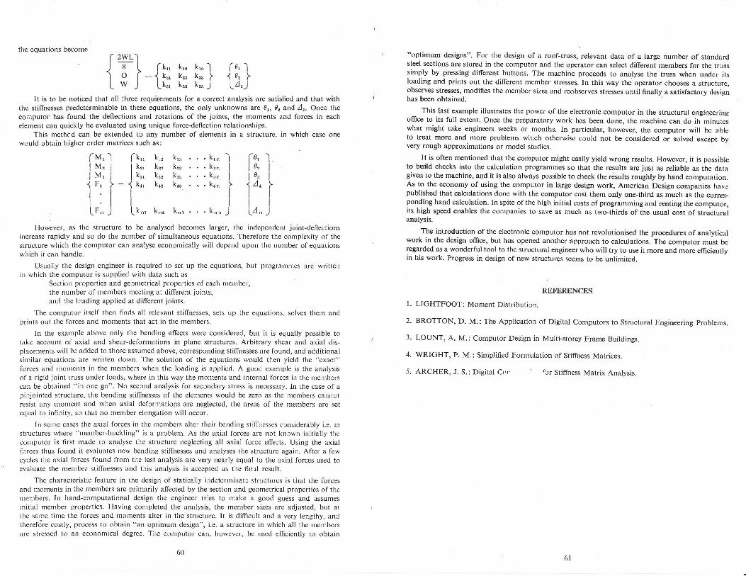
tlre equations become
r 2wl.l) 8 L fk,, k,, k,"I fd, II o l----{kfl k2 kr" I {d, II w J Lk,. k", k* j lA,)
-l r'0, l
I 10" II la' I| 1',' i) l^")
It is to be noticed that all three requirements for a correct analysis are satisfied and that withtlrc stiffnesses predeterminable in these equations, the only unknowns are 0r, 0, and /". Once theconlputor has found the deflections and rotations of the joints, the moments and forces in each
element can quickly be evaluated using unique force-deflection telationships.This methcd can be extended to any number of elements in a structure, in which case one
would obtain higher crder matrices such as:
k., kr" . . . krnkP k8 '..k2nku kr, ...krnko, kn, . .. . knn
k,, k.r...kn.
However, as tlre structure to be analysed becomes larger, the independent joint-deffectionsincrease rapidly and so do the number of simultaneous equations. Tlrerefore the complexity of thestructure which the conputor can analyse economically will depend upon the nurrber of equationswhich it can lrandle.
Usually the design engineer is required to set up the equations, but progranrnres are writteuin which the computor is supplied with data such as
Section properties and gecmetrical properties of each member,the number of members nreeting at different joints,and the loading applied at different joints.
The computor itself then finds all relevant stiffnesses, sets up the equations, solves them andprints out the forces and moments that act in the members.
In the example above only the bending effects were considered, but it is equally possible totake account of axial and shear-deformations in plane structures. Arbitrary shear and axial dis-placements will be added to those assumed above, corresponding stiffnesses are found, and additionalsimilar equations are written down. The solution of the equations would then yield the "exact"forces and monents in the members when the loading is applied. A good example is the analysisof a rigid .joint truss under loads, where in this way the moments and internal forces in the memberscan be obtained "in one go". No second analysis for secondary stress is necessary. In the case of apinjointed structure, the bending stiffnesses of the elements would be zero as the members cannctresist any moment and when axial defornrations are neglected, tlie areas of the members are setequal to infinity, sc that no member elongation will occur.
ln some cases the axial forces in tire members alter their bending stiffnesses ccnsiderably i.e. rnstructures where "member-buckling" is a problen-r. As the axial forces are not known initially thecol.nputor is first rnade to analyse the structure neglecting all axial force effects. Using the axialforces thlrs found it evaiuates new bending stiffnesses and analyses the structure again. After a fewcycles tl-re axial forces found from the last analysis are very nearly equal to the axial forces useC toevaluate the member stiffnesses and this analysis is accepted as the finrl result.
The cl-raracteristic leature in the design of statically indeterminate strLlctures is that the forcesand moments in the n-rerrbers are primarily affected by the section and geometrical properties of therurembers. In hand-computational design the engineer tries to make a good guess and assumesinitial menrber properties. Having completed the analysis, the member sizes are adjusted, but attlle san'le time the forces and lronlents alter in the structure. It is dimcult and a very lengthy, andtherefdre costly, process to obtain "an optinrunr design", i.e. a structure in which all the membersare stressed to an econonrical degree. The computor can, however, be used efficiently to obtain
"optimum designs". For the design of a roof-truss, relevant data of a large number of standardsteel sections are stored in the computor and the operator can select different members for the trusssimply by pressing different buttons. The machine proceeds to analyse the truss when under itsloading and prints out the different mernber stresses. In this way the operator chooses a structure,observes stresses, modifies the member sizes and reobserves stresses until finally a satisfactory designhas been obtained.
This last example illustrates the power of the electronic computorin the structural engineeringoffice to its full extent. Once the preparatory work has been done, the machine can do ih minuteswhat might take engineers weeks or months. In particular, however, the computor will be ableto treat more and more problems which otherwise could not be considered or solved except byvery rough approximations or model studies.
It is often mentioned that the computor might easily yield wrong results. However, it is possibleto build checks into the calculation programmes so. that the results are just as reliable as the datagiven to the machine, and it is also always possible to check the results roughly by hand computation.As to the economy of using the computor in large design work, American Design companies havepublished that calculations done with the computor cost them only one-third as much as the corres-ponding hand calculation. In spite of the high initial costs of programming and renting the computor,its high speed enables the companies to save as much as two-thirds of the usual cost of structuralanalysis.
The introduction of the electronic computor has not revolutionised the procedures of analyticalwork in the design office, but has opened another approach to calculations. The computor nust beregarded as a wonderful tool to the structural engineer who will try to use it more and more efficientlyin his work. Progress in design ofnew structures seems to be unlimited,
REFERENCES
1. LIGHTFOOT: Moment Distribution.
2' BROTTON, D. M.: The Application of Digital Computors to Structural Engineering problenrs.
3. LOUNT, A. M.: Computor Design in Multi-storey Frame Buildings.
4. WRIGHT, P. M,: Simplified Formulation of Stiffness Matrices.
5. ARCHER, J. S.: Digital Cnr t'or Stiffness Matrix Analysis.
[tut, l (k,,lM, I lk,,Irur, I lk,,{Fn l:1k,,rrll-trLr" J Lkn,
6061