load analysis and application - in.gov · indiana department of transportation—2012 design manual...
TRANSCRIPT

INDIANA DEPARTMENT OF TRANSPORTATION—2012 DESIGN MANUAL
CHAPTER 403
Load Analysis and Application
Design Memorandum
Revision Date
Publication Date*
Sections Affected
12-20 Oct. 2012 Jan. 2013 403-3.05, 403-3.07, 403-4.02 Figures 403-3F, 403-4A
*Revisions will appear in the next published edition of the Indiana Design Manual.
NOTE: References to material in 2011 Design Manual have been highlighted in blue throughout this document.
2012

TABLE OF CONTENTS
TABLE OF CONTENTS ................................................................................................................ 2
LIST OF FIGURES ........................................................................................................................ 3
403-2A Typical Dead Loads ................................................................................................ 3
403-3A Toll Road Loading No.1 (W = 90 kip) ................................................................... 3
403-3B Toll Road Loading No. 2 (W = 90 kip) .................................................................. 3
403-3C Special Toll Road Truck (W = 126 kip) ................................................................. 3
403-3D Michigan Truck Train No. 5 (W = 134 kip) ........................................................... 3
403-3E Michigan Truck Train No. 8 (W = 134 kip) ........................................................... 3
403-4A Construction-Loadings Information to be Shown on General Plan ........................ 3
403-4B Construction Loads ................................................................................................. 3
403-4C Applied Construction Loads ................................................................................... 3
403-4D Beam Rotation ........................................................................................................ 3
CHAPTER 403 ............................................................................................................................... 4
403-1.0 GENERAL........................................................................................................................ 4
403-1.01 Introduction .............................................................................................................. 4
403-1.02 Limit States ............................................................................................................... 4
403-2.0 PERMANENT LOADS ................................................................................................... 6
403-2.01 General Requirements .............................................................................................. 6
403-2.02 Uplift ......................................................................................................................... 7
403-2.03 Concrete Deck Slab .................................................................................................. 7
403-2.04 Utilities ..................................................................................................................... 7
403-2.05 Dead-Load Values .................................................................................................... 7
403-2.06 Dead-Load Distribution ............................................................................................ 7
403-3.0 TRANSIENT LOADS ...................................................................................................... 8
403-3.01 Toll Road and Michigan-Train Design Trucks ......................................................... 8
403-3.02 Centrifugal and Braking Forces, and Wind Pressure on Vehicle ............................. 9
403-3.03 Stream Pressure ........................................................................................................ 9
403-3.04 Forces Due to Friction .............................................................................................. 9
403-3.05 Earthquake Effects .................................................................................................... 9
403-3.06 Ice Forces on Pier ..................................................................................................... 9
403-3.07 Vehicle or Train Collision with Structure ................................................................ 9
403-3.08 Vessel Collision with Structure .............................................................................. 10
403-3.09 Pedestrian Live-Load Distribution ......................................................................... 10
403-4.0 CONSTRUCTION LOADINGS .................................................................................... 10
403-4.01 General Requirements ............................................................................................ 10
403-4.02 Application of Construction Loadings ................................................................... 11
2012

403-5.0 ELASTIC STRUCTURAL ANALYSIS ........................................................................ 11
403-5.01 General.................................................................................................................... 12
403-5.02 Superimposed Deformations ............................................................................ 12
LIST OF FIGURES
Figure Title 403-2A Typical Dead Loads
403-3A Toll Road Loading No.1 (W = 90 kip)
403-3B Toll Road Loading No. 2 (W = 90 kip)
403-3C Special Toll Road Truck (W = 126 kip)
403-3D Michigan Truck Train No. 5 (W = 134 kip)
403-3E Michigan Truck Train No. 8 (W = 134 kip)
403-4A Construction-Loadings Information to be Shown on General Plan
403-4B Construction Loads
403-4C Applied Construction Loads
403-4D Beam Rotation
2012
CHAPTER 403
Load Analysis and Application
403-1.0 GENERAL
References shown are to the AASHTO LRFD Bridge Design Specifications. 403-1.01 Introduction
This Chapter describes the loads to be applied to bridge structures. The following summarizes the discussion of structural loads and force effects. 1. Permanent Loads. This consists of the application of alternative sets of load factors
specified for permanent loads and for imposed deformations. 2. Gravitational Live Load. This Chapter provides a treatment on vehicular live loads with
reference to the following:
a. the live-load regime as a tandem or truck coincident with a uniformly distributed load, as specified in the LRFD Specifications; and
b. a description of heavy vehicles permitted to operate in the State for which certain
bridges shall be investigated. 3. Creep, Shrinkage, and Temperature. The use of alternative load factors, introduced by
the LRFD Specifications for the effects of creep, shrinkage, and uniform temperature, is discussed. See Section 403-5.02.
4. Earthquake. Section 403-3.05 discusses earthquake effects. 5. Ice. Section 403-3.06 discusses ice forces on a pier. 403-1.02 Limit States
2012

LRFD 1.3.1 states that bridges shall be designed for specified limit states to achieve the objectives of constructibility, safety and serviceability, with due regard to issues of inspectability, economy and aesthetics. Through this requirement, the Specifications expand the traditional family of design objectives of constructibility, safety, and economy by means of concerns for maintenance and social issues. The first relates to the Specifications’ requirement of 75 years for a reasonably trouble-free service life, and the second reflects the pleasure and comfort of the highway user. LRFD Section 2 provides guidance on how the 75-year target service life can be achieved, and thus emphasizes the significance of non-strength issues. For the purpose of this Chapter, the extreme-limit state applies to both maximum and minimum loads. Components and connections of a bridge are designed for strength, or derivatives of strength, at various limit states. The basic design relationship between load effects and structural performance for all limit states is as follows: niii RQ (Equation 403-1.1)
Where: i = load factor Qi = load or force effect = resistance factor Rn = nominal resistance For a load for which a maximum value of γi is appropriate, IRDi 0.95 For a load for which a minimum value of γi is appropriate, 0.11
IRDi
where IRD ,, are load modifiers relating to ductility, redundancy, and operational importance, respectively.
The left-hand side is the sum of the factored load, or force, effects of a type of effect acting on a component, and the right-hand side is the factored nominal resistance of the component for the type of effect. Where various types of force effects interact at a section of a component, e.g., shear and moment in a concrete beam, or where a load produces both force effect and resistance, e.g., fill behind a retaining wall, either special interaction formulas are provided in the LRFD Specifications or the effects are artificially separated for design. The strength-limit-state factors to be used are as follows:
2012

D = 1.05 for components subject to brittle failure D = 1.00 for conventional design in accordance with the LRFD Specifications R = 1.05 for a simple span with non-integral supports or non-redundant structure R = 1.00 for other type of bridge I = 1.05 for a National Highway System bridge, or a bridge which provides single access to a military base, medical facility, generating station, or a considerable population I = 0.95 for a highway classified as a local road or street I = 1.00 for a bridge on another type of highway In addition to the LRFD Specifications, the following shall apply to the application of limit states. Limit State Investigation Strength II If special-permit vehicles, such as trucks carrying large transformers are
anticipated, they shall be analyzed under this limit state. Wind load need not be considered.
403-2.0 PERMANENT LOADS
403-2.01 General Requirements
LRFD 3.5 specifies the types of permanent loads, which are either direct gravity loads or those caused by gravity loads. These now include downdrag, DD, which is the result of soil consolidation around a deep foundation. Prestressing is considered part of resistance and has been omitted from the list of permanent loads shown in LRFD 3.5. However, in designing anchorage blocks and evaluating shear resistance, the prestressing force is contributing to load effects. It can sometimes be the dominating load. As shown in LRFD Table 3.4.1-2, there are two sets of load factors for permanent loads. They shall be applied where the sum of force effects can be both positive and negative. For example, this situation can occur in the end bearing design of a continuous superstructure with relatively shortened spans. Where the transient live load is in the end span, it causes compression and, if in the second span, uplift. The following combinations shall be considered in this situation. 1. If dead-load reaction is compressive, for extreme compression use the maximum load
factor. For extreme uplift, use the minimum load factor. 2. If dead-load reaction is tensile, for extreme compression use the minimum load factor.
For extreme uplift, use the maximum load factor.
2012

The load factor for a given loading situation shall be the same for all spans. 403-2.02 Uplift
Uplift had been formerly treated as a separate loading situation. With the introduction of variable load factors, uplift has been reduced to one of the load combinations. 403-2.03 Concrete Deck Slab
If a concrete deck slab is placed on stay-in-place corrugated metal formwork as described in LRFD 9.7.4, the specified net concrete design section shall be taken from the top of the form. The design dead load shall include 15 psf of deck area for a deck formed with permanent metal forms to accommodate the weight of the forms and of the concrete in the valleys of the forms’ corrugations. Clear spans between girders or beams exceeding 9.5 ft will require metal forms with the corrugations closed off, which prohibit concrete from entering the valleys of the corrugations. The girders or beams, however, shall still be designed for 15 psf of deck area. Although permanent metal deck forms, which provide a dead load of less than 15 psf, are available, the 15 psf shall be retained as the minimum design load. In addition to the dead load of the initial structure, the design dead load shall be increased by 35 psf for a future wearing surface or overlay. 403-2.04 Utilities
Information shall be obtained concerning the weight and location of utilities that may be attached to the bridge. 403-2.05 Dead-Load Values
Figure 403-2A lists typical dead-load values. 403-2.06 Dead-Load Distribution
Typical practices for distributing dead load to beams or girders are as follows.
2012

1. Future-wearing-surface load shall be applied equally to all beams. 2 Dead loads due to barrier railings, curbs, sidewalks, or other attachments (structural or
aesthetic) placed after the deck has set, shall be distributed with 60% of the load applied to the exterior beam and 40% of the load applied to the first adjacent interior beam. The beams shall also be checked with the loads distributed equally to all beams.
3. Concrete dead load of deck applied to the outside girder shall be in accordance with the
lever rule described in LRFD 4.6.2.2.1. 4. The capacity of outside beams shall not be less than the capacity of interior beams. All
interior beams shall be equally sized. 5. For utilities, the lever rule can be used to compute the load to the adjacent beams. 403-3.0 TRANSIENT LOADS
403-3.01 Toll Road and Michigan-Train Design Trucks
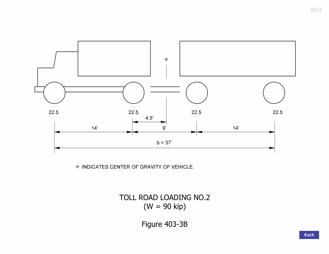
Each bridge shall be designed for the HL-93 vehicular live load described above. In addition, a series of design truck loads shall be used as described as follows. 1. Toll Road Live Load. In addition to the Specifications’ live-load regime, the Toll Road
live load shall be applied to each State-highway bridge located within 15 mi of an Indiana Toll Road gate. A single truck with design lane load shall be used in each design lane. This loading shall be investigated under Strength II Limit State. The configurations of the Toll Road live-load vehicles are shown in Figures 403-3A, 403-3B, and 403-3C. Factors for multiple presence and dynamic load allowance shall be the same as those used for regular design trucks.
2. Michigan Truck-Train Live Load. In addition to the Specifications’ live load regime, the
Michigan Truck-Train live load shall be applied to each bridge located on the Indiana Extra-Heavy-Duty-Highway System. A complete list of the locations of these highways appears at http://codes.lp.findlaw.com/incode/9/20/5/9-20-5-4. The configurations of the Michigan Truck-Train vehicles are shown in Figures 403-3D and 403-3E. A single truck with design lane load shall be limited to one design lane located so as to cause extreme force effects, while the other design lanes are occupied by regular design loads. This loading combination shall be investigated under the Strength II Limit State. Factors for multiple presence and dynamic load allowance shall be the same as those used for regular design trucks.
2012

These design trucks shall not be considered for fatigue considerations, but they may be used for centrifugal and braking forces. 403-3.02 Centrifugal and Braking Forces, and Wind Pressure on Vehicle
Centrifugal forces, braking forces, and wind pressure on a vehicle shall be applied at 6 ft above the profile grade at the centerline of the pier or bent. 403-3.03 Stream Pressure
A drag coefficient, CD, shall be used as described in LRFD 3.7.3.1. 403-3.04 Forces Due to Friction
Chapter 409 discusses friction forces within the context of bearings. 403-3.05 Earthquake Effects
Earthquake Effects, EQ, shall be determined in accordance with AASHTO Guide Specifications for LRFD Seismic Bridge Design. 403-3.06 Ice Forces on Pier
The following describes criteria for determining ice forces on a pier. 1. Effective ice crushing strength, p = 165 psi. 2. Ice thickness, t = 1 ft. 3. The horizontal force shall be applied midway between the Q100 elevation, i.e., the water
elevation at the 100-year frequency flood event, and the low-water elevation. 4. If the low-water channel width is less than 60 ft, a reduction factor, K1, of 0.75, and p =
55 psi, shall be used. 5. LRFD Specifications 3.9.3, 3.9.4, 3.9.5, and 3.9.6 do not apply. 403-3.07 Vehicle or Train Collision with Structure
2012

Unless the structure is protected as specified in LRFD 3.6.5.1, an abutment or pier located within 30 ft of the edge of a roadway, or within 50 ft of the centerline of a railroad track, shall be designed for loads in accordance with LRFD 3.6.5.2. A mechanically-stabilized-earth-wall bridge abutment placed adjacent to a roadway need not be checked for vehicle-collision forces as described in LRFD 3.6.5. However, if the wall must be placed inside the clear zone, roadway safety shall be addressed. Such an abutment placed adjacent to a railroad track shall be checked as described in LRFD 3.6.5. 403-3.08 Vessel Collision with Structure
In a navigable waterway, a merchant ship or barge can collide with a bridge substructure. The bridge structure shall be designed using load combination Extreme Event II to prevent collapse of the superstructure by considering the size and type of the vessel, available water depth, vessel speed, and structure response in accordance with LRFD 3.14. For additional information, see the AASHTO Guide Specification and Commentary for Vessel Collision Design of Highway Bridges. The design water depth shall be computed from the bottom of the waterway to the annual mean high-water level. 403-3.09 Pedestrian Live-Load Distribution
Pedestrian live loads shall be evaluated for each of the conditions as follows. 1. Based on the assumption that all sidewalks can be removed in the future; vehicles are
permitted to travel from face-of-barrier to face-of-barrier. A pedestrian live load is not applied to the structure.
2. Pedestrian live load shall be distributed with 60% of the load applied to the exterior beam
and 40% of the load applied to the first adjacent interior beam. Vehicles are permitted to travel from face-of-curb to face-of-curb.
403-4.0 CONSTRUCTION LOADINGS
403-4.01 General Requirements
Construction loadings shall be evaluated in accordance with LRFD 3.4.2.
2012
Construction loadings are not accurately known during the project-design stage. The magnitude and location of the assumed construction loadings used for design, however, shall be shown in the contract documents. For a beam or girder structure, the information shown in Figure 403-4A shall be shown on the General Plan. The exterior beam or girder shall be checked for the specified construction loadings: All additional rotational resistance measures required as a result of the construction loading check shall be shown on the plans. 403-4.02 Application of Construction Loadings
1. Component Loads, DC.
a. DC1, Concrete = 150 pcf
b. DC2, Stay-in-place Formwork = 15 psf 2. Construction Dead Loads, CDL. a. CDL1, Removable Coping Deck Forms = 15 psf
b. CDL2, Temporary Walkway = 15 psf, applied over a 2-ft width platform on outside of coping
3. Construction Live Loads, CLL.
a. CLL1, Construction Live Load = 20 psf extended the entire bridge width plus 2 ft outside of bridge coping over 30 ft longitudinal length centered on screed-machine load
b. CLL2, Screed Machine = 4500 lb over 10 ft longitudinal length applied 6 in. outside the bridge coping
c. CLL3, Vertical Railing and Walkway Load = 75 plf applied 6 in. outside the bridge coping over 30 ft longitudinal length centered on screed-machine load
4. Wind Load, WS. WS, Wind on Structure = 50 psf in accordance with AASHTO Guide
Design Specifications (1995) for Bridge Temporary Works, Fig. 2.1 The angled bracket shall be assumed to extend from the flange/web intersection to 6 in. outside the edge of coping to maximize the horizontal force. Figures 403-4B, 403-4C, and 403-4D depict the application of these loads and the resultant girder rotation. 403-5.0 ELASTIC STRUCTURAL ANALYSIS
2012

403-5.01 General
This Section discusses the effects of imposed deformations such as elastic shortening, creep, shrinkage, temperature, and settlement. 403-5.02 Superimposed Deformations
Superimposed deformations include the following: 1. elastic shortening; 2. creep; 3. shrinkage; 4. temperature; and 5. settlement. With the exception of settlement, all of these deformations are internally generated. More discussion on sectional, i.e., internal, effects of these imposed deformations is provided in Chapter 406. The LRFD Specifications specify various load factors for these effects. The 1.20 factor relates to the fact that the movement calculated on the basis of specified values may occasionally be exceeded and helps to avoid the undersizing of joints, expansion devices, and bearings. The poor performance of many deck joints and expansion bearings can be traced to an underestimate of extreme movements of retaining walls and abutments due to earth pressure or pavement expansion which can be cumulative with the effects of the other three. Deck joints frozen due to substructure movements are often reported. A pavement relief joint is provided at the end of each reinforced-concrete bridge-approach pavement, and the effect of pavement expansion can be neglected. The governing combinations of the effects of creep, shrinkage, and uniform temperature shall be determined in accordance with the LRFD Specifications. The substructure displacement shall be determined considering strain or relative structural movement, whichever applies, and multiplying it by 1.20. If a calculated force effect is a direct response to creep, shrinkage, and uniform temperature, a load factor of 0.50 for the strength-limit state, and one of 1.00 for the service-limit state shall be used. In theory, a load factor of less than 1.00 signifies that the effects of superimposed deformation tend to dissipate at the strength-limit state due to inelastic action. This may be further reduced if so justified by inelastic analysis. If the calculated force effect is an indirect response, such as for altering eccentricity of gravitational or other loads, the load factors specified for these loads shall be applied, but the eccentricity caused by the deformation shall be upgraded by a factor of 1.2.
2012

Indiana is considered to be in a cold climate. A setting temperature of 60 F shall be used for the installation of expansion bearings and expansion deck joints.
2012

Dead Load Value
Future wearing surface 35 lb/ft
Permanent metal deck forms
2
15 lb/ft
Reinforced concrete
2
150 lb/ft
Earth
3
120 lb/ft
Water
3
62.4 lb/ft
Lateral soil pressure
3
(Equivalent fluid pressure) 32.5 lb/ft
3
TYPICAL DEAD LOADS
Figure 403-2A
2012

INDICATES CENTER OF GRAVITY OF VEHICLE.
18 18 18 18 18
4’10’
14"
4’
b = 28’
10’
TOLL ROAD LOADING NO.1
(W = 90 kip)
Figure 403-3A
2012
INDICATES CENTER OF GRAVITY OF VEHICLE.
22.5 22.5 22.5 22.5
14’14’ 9’
4.5’
b = 37’
TOLL ROAD LOADING NO.2
(W = 90 kip)
Figure 403-3B
2012

INDICATES CENTER OF GRAVITY OF VEHICLE.
18 18 18 18 18 18 18
20’12’4’
5’-8.5"
10’ 4’ 26’
b = 76’
SPECIAL TOLL ROAD TRUCK
(W = 126 kip)
Figure 403-3C
2012

INDICATES CENTER OF GRAVITY OF VEHICLE
12 16 16
9’ 3’-6" 9’
18 181’-4.8"
9’ 9’
b = 57’-6"
18 18 18
9’9’
MICHIGAN TRUCK TRAIN NO. 5
(W = 134 kip)
Figure 403-3D
2012

INDICATES CENTER OF GRAVITY OF VEHICLE
12 13 13 11 11
9’ 9’3’-6"
11 11 11 11
3’-6"
2.9"
b = 57’
9’ 9’
15 15
MICHIGAN TRUCK TRAIN NO. 8
(W = 134 kip)
Figure 403-3E
2012

CONSTRUCTION LOADING The exterior girder has been checked for strength, deflection, and overturning using the constructions loads shown below. Cantilever overhang brackets were assumed for support of the deck overhang past the edge of the exterior girder. The finishing machine was assumed to be supported 6 in. outside the vertical coping form. The top overhang brackets were assumed to be located 6 i n. past the edge of the vertical coping form. T he bottom overhang brackets were assumed to be braced against the intersection of the girder bottom flange and web. Deck Falsework Loads: Designed for 15 l b/ft2 for permanent metal stay-in-place deck
forms, removable deck forms, and 2-ft exterior walkway. Construction Live Load: Designed for 20 lb/ft2 extending 2 ft past the edge of coping and 75
lb/ft vertical force applied at a distance of 6 in. outside the face of coping over a 30-ft length of the deck centered with the finishing machine.
Finishing-Machine Load: 4500 lb distributed over 10 ft along the coping. Wind Load: Designed for 70 m ph horizontal wind loading of 50 l b/ft2 in
accordance with AASHTO Guide Design Specifications for Bridge Temporary Works (1995), Figure 2.1.
CONSTRUCTION-LOADINGS INFORMATION TO BE SHOWN ON GENERAL PLAN
Figure 403-4A
2012

(WS)
Wind
Overhang Bracket
2’-0"
Midpoint of
Coping
6"
Edge of Coping
(DC1)
Concrete
Construction Live Load (CLL1)
(CDL1) + Walkway (CDL2)] &
Formwork [SIP (DC2) + Removable
Deck Forms
Stay-in-Place
(CLL2 & CLL3)
Figure 403-4B
CONSTRUCTION LOADS
Rail Load
Screed Machine,
2012

Overhang Bracket
Midpoint of
CopingDeck Forms
Stay-in-Place
Figure 403-4C
CONSTRUCTION LOADS
Construction Loads & Formwork
Screed Machine, Rail Loads, Concrete
Horizontal and Vertical components of Concrete, Formwork, Construction Loads
Wind
Vertical Loads transmitted through bracket Vertical Loads directly to Girder
2012

Construction Loads & Formwork
Screed Machine, Rail Loads, Concrete
Horizontal and Vertical components of
Figure 403-4D
BEAM ROTATION
Equates To
Y-Axis
Y-Axis
Construction Loads
Concrete, Formwork,
2012