load bearing profile
TRANSCRIPT
LOAD BEARINGPROFILELG153-840
LANGUAGEEN

LG153-840
3
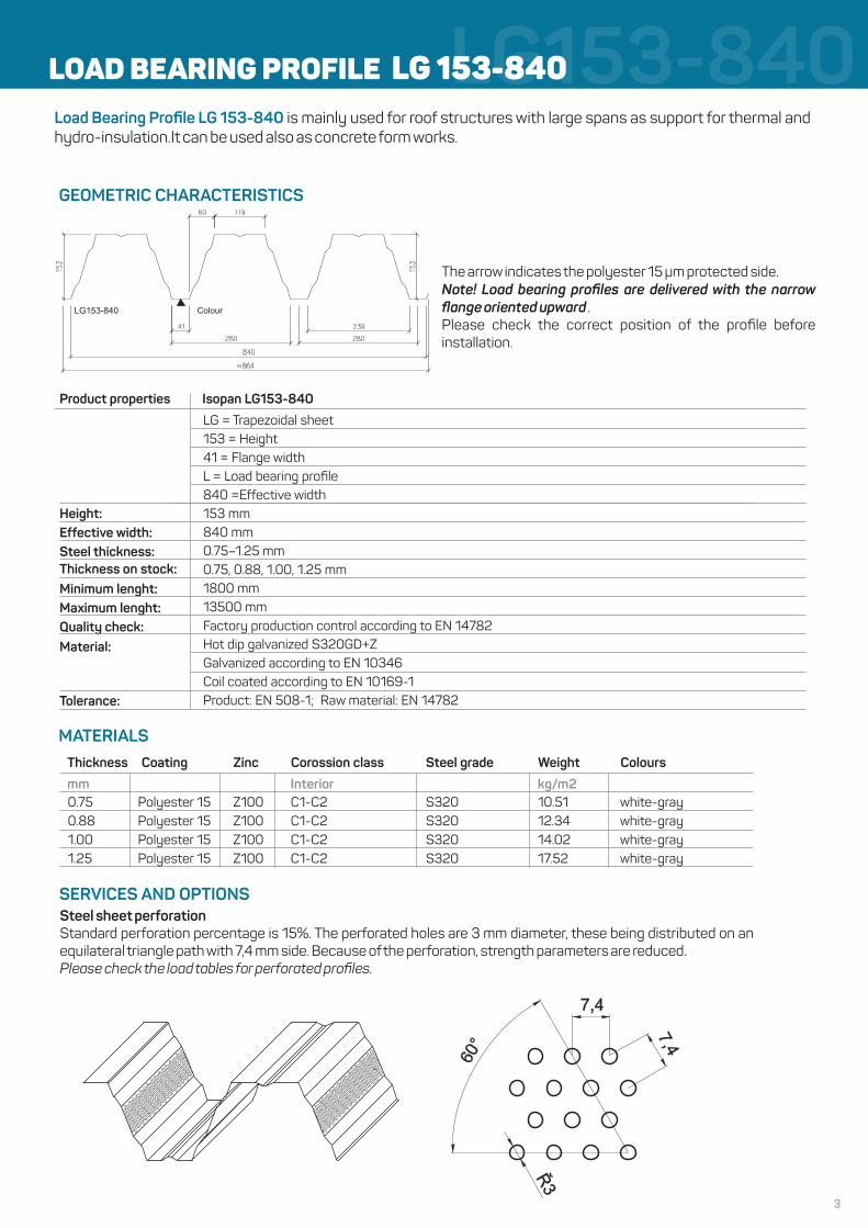
LOAD BEARING PROFILE LG 153-840Load Bearing Profile LG 153-840 is mainly used for roof structures with large spans as support for thermal and hydro-insulation.It can be used also as concrete form works.
GEOMETRIC CHARACTERISTICS
The arrow indicates the polyester 15 µm protected side.Note! Load bearing profiles are delivered with the narrow flange oriented upward .Please check the correct position of the profile before installation.
Product properties Isopan LG153-840
LG = Trapezoidal sheet153 = Height41 = Flange widthL = Load bearing profile840 =Effective width153 mm840 mm0.75–1.25 mm0.75, 0.88, 1.00, 1.25 mm1800 mm13500 mmFactory production control according to EN 14782Hot dip galvanized S320GD+ZGalvanized according to EN 10346Coil coated according to EN 10169-1Product: EN 508-1; Raw material: EN 14782
Height:Effective width:Steel thickness:Thickness on stock:Minimum lenght:Maximum lenght:Quality check:Material:
Tolerance:
MATERIALSThickness
0.750.881.001.25
Coating Zinc Corossion class Steel grade Weight Colours
Interior kg/m2mmPolyester 15Polyester 15Polyester 15Polyester 15
Z100Z100Z100Z100
C1-C2C1-C2C1-C2C1-C2
S320S320S320S320
10.5112.3414.0217.52
white-graywhite-graywhite-graywhite-gray
Steel sheet perforationStandard perforation percentage is 15%. The perforated holes are 3 mm diameter, these being distributed on an equilateral triangle path with 7,4 mm side. Because of the perforation, strength parameters are reduced.Please check the load tables for perforated profiles.
SERVICES AND OPTIONS
Colour
4
LG153-840LG153-840-Positive-Narrow flange against support
Thick[mm] State
Span lenght L [m]
4.00 4.25 4.50 4.75 5.00 5.25 5.50 5.75 6.00 6.25 6.50 6.75 7.00 7.25 7.50 7.75 8.00 8.25 8.50 8.75 9.00
0.75
1. USL 5.95 5.26 4.68 4.19 3.76 3.41 3.09 2.82 2.58 2.37 2.18 2.01 1.86 1.73 1.61 1.50 1.40 1.31 1.23 1.15 1.08
2. L/150 6.25 5.19 4.36 3.69 3.15 2.71 2.34 2.03 1.78 1.56 1.38 1.22 1.08 0.96 0.86 0.77 0.69 0.62 0.56 0.50 0.46
3. L/200 4.66 3.87 3.24 2.74 2.33 2.00 1.73 1.51 1.31 1.15 1.01 0.89 0.79 0.70 0.62 0.55 0.49 0.44 0.39 0.35 0.32
4. L/300 3.07 2.55 2.13 1.79 1.52 1.30 1.12 0.97 0.84 0.73 0.64 0.56 0.49 0.43 0.38 0.33 0.29 0.26 0.22 0.20 0.18
1.00
1. USL 8.70 7.69 6.84 6.12 5.51 4.98 4.53 4.13 3.78 3.47 3.20 2.95 2.73 2.54 2.36 2.20 2.05 1.92 1.80 1.69 1.59
2. L/150 8.78 7.30 6.12 5.19 4.43 3.80 3.29 2.86 2.50 2.20 1.94 1.72 1.53 1.36 1.21 1.09 0.97 0.87 0.79 0.71 0.64
3. L/200 6.55 5.43 4.55 3.85 3.28 2.82 2.43 2.11 1.84 1.61 1.42 1.25 1.11 0.98 0.88 0.78 0.70 0.62 0.56 0.50 0.45
4. L/300 4.32 3.58 2.99 2.52 2.15 1.83 1.58 1.36 1.18 1.03 0.90 0.79 0.69 0.61 0.54 0.47 0.41 0.37 0.32 0.29 0.25
1.25
1. USL 11.20 9.90 8.81 7.88 7.10 6.41 5.83 5.32 4.86 4.47 4.12 3.80 3.52 3.27 3.04 2.84 2.64 2.47 2.32 2.18 2.05
2. L/150 11.01 9.15 7.68 6.51 5.56 4.77 4.13 3.59 3.14 2.76 2.44 2.16 1.91 1.70 1.52 1.36 1.22 1.10 0.99 0.90 0.81
3. L/200 8.22 6.82 5.72 4.84 4.12 3.53 3.05 2.65 2.31 2.02 1.78 1.57 1.39 1.24 1.11 0.98 0.88 0.78 0.70 0.63 0.57
4. L/300 5.42 4.49 3.75 3.17 2.69 2.30 1.98 1.72 1.48 1.29 1.13 0.99 0.87 0.77 0.68 0.60 0.53 0.47 0.41 0.36 0.32
No. Thickness Weight Tensile strengthLimit yield point Zinc Coating
nominal coreA tnom t g Zn SP 15
B mm mm kg/m2 g/m² m
1. 0.75 0.74 10.51 100 15
2. 0.88 0.87 12.34 100 15
3. 1.00 0.99 14.02 100 15
4. 1.25 1.24 17.52
f y
MPa
320.0
320.0
320.0
320.0
fu
MPa
390.0
390.0
390.0
390.0 100 15
Effective widthMaximum width
]mm[]mm[
048468
Dimensioning tables according to EN 1993-1-3.Compare design load where safety factors must be included to table values (1.ULS).Serviceability limit state safety factors = 1.0.Self-weight of the sheet has been taken into account with 1.35 safety factorContinuous uniform load in [kN/m2].
1.Ultimate limit state (ULS; Q).2.Serviceability limit state. Deflection limit f = L/150 (SLS; Q ).ch
3.Serviceability limit state. Deflection limit f = L/200 (SLS; Q ).ch
4.Serviceability limit state. Deflection limit f = L/300 (SLS; Q ).ch
1. Span structureL
Material factor g = 1.0M1
End support width: 60 mmMiddle support width: 160 mm
280
119
~864
840
161
280
153
41 60colour
core
0.88
1. USL 7.52 6.65 5.91 5.29 4.76 4.31 3.91 3.56 3.26 2.99 2.76 2.55 2.36 2.19 2.04 1.90 1.77 1.66 1.55 1.46 1.37
2. L/150 7.56 6.28 5.27 4.47 3.81 3.28 2.83 2.46 2.16 1.89 1.66 1.48 1.31 1.17 1.04 0.93 0.84 0.75 0.67 0.61 0.55
3. L/200 5.64 4.67 3.92 3.32 2.82 2.43 2.09 1.82 1.58 1.38 1.23 1.08 0.95 0.84 0.75 0.67 0.60 0.53 0.48 0.43 0.38
4. L/300 3.72 3.08 2.58 2.18 1.85 1.58 1.36 1.17 1.01 0.89 0.77 0.68 0.60 0.52 0.45 0.40 0.35 0.32 0.28 0.24 0.21
µ
5
LG153-840-Positive-Narrow flange against support
4.00 4.25 4.50 4.75 5.00 5.25 5.50 5.75 6.00 6.25 6.50 6.75 7.00 7.25 7.50 7.75 8.00 8.25 8.50 8.75 9.00
4.00 4.25 4.50 4.75 5.00 5.25 5.50 5.75 6.00 6.25 6.50 6.75 7.00 7.25 7.50 7.75 8.00 8.25 8.50 8.75 9.00
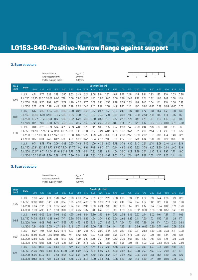
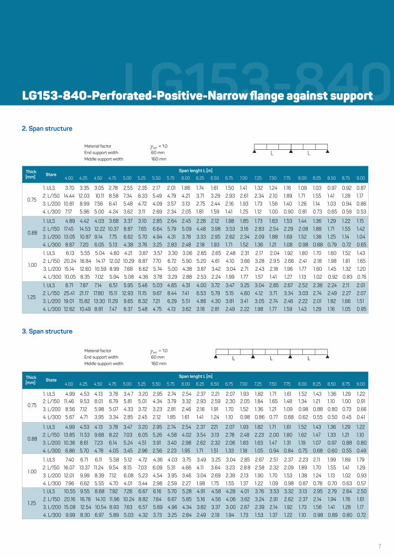
2. Span structure
0.75
1. ULS 4.14 3.75 3.41 3.12 2.86 2.63 2.43 2.24 2.08 1.94 1.81 1.69 1.58 1.49 1.39 1.31 1.23 1.16 1.10 1.03 0.98
2. L/150 15.25 12.7 0 10.68 9.06 7.76 6.68 5.80 5.06 4.45 3.92 3.47 3.09 2.76 2.48 2.22 2.01 1.82 1.65 1.49 1.36 1.24
3. L/200 11.41 9.50 7.99 6.77 5.79 4.99 4.32 3.77 3.31 2.91 2.58 2.29 2.04 1.83 1.64 1.48 1.34 1.21 1.10 1.00 0.91
4. L/300 7.57 6.29 5.28 4.48 3.82 3.29 2.85 2.48 2.17 1.91 1.68 1.49 1.33 1.18 1.06 0.95 0.86 0.77 0.69 0.63 0.57
0.88
1. ULS 5.51 4.99 4.54 4.15 3.80 3.50 3.22 2.98 2.77 2.57 2.40 2.24 2.10 1.96 1.84 1.74 1.63 1.54 1.45 1.38 1.30
2. L/150 18.40 15.31 1 2.88 1 0.94 9.35 8.06 7.00 6.11 5.37 4.74 4.19 3.73 3.33 2.99 2.69 2.43 2.19 1.99 1.81 1.65 1.51
3. L/200 13.7 7 1 1.45 9.63 8.17 6.99 6.02 5.22 4.55 3.99 3.52 3.11 2.77 2.47 2.21 1.98 1.78 1.61 1.46 1.32 1.21 1.09
4. L/300 9.14 7.60 6.38 5.40 4.62 3.97 3.44 2.99 2.62 2.30 2.03 1.80 1.61 1.44 1.28 1.15 1.04 0.94 0.84 0.76 0.69
1.00
1. ULS 6.86 6.20 5.63 5.14 4.71 4.33 4.00 3.70 3.43 3.18 2.97 2.77 2.59 2.43 2.28 2.14 2.02 1.91 1.80 1.70 1.61
2. L/150 21 .33 17 .7 6 14.94 1 2.68 1 0.85 9.36 8.12 7.08 6.22 5.49 4.87 4.33 3.87 3.47 3.12 2.81 2.54 2.31 2.10 1.91 1.75
3. L/200 1 5.97 1 3.28 1 1 .1 7 9.47 8.11 6.98 6.05 5.28 4.63 4.08 3.61 3.21 2.86 2.56 2.30 2.07 1.87 1.69 1.54 1.40 1.27
4. L/300 10.59 8.81 7.40 6.27 5.35 4.61 3.99 3.47 3.04 2.67 2.36 2.10 1.87 1.67 1.49 1.34 1.20 1.09 0.98 0.89 0.80
1.25
1. ULS 9.51 8.58 7.79 7.09 6.48 5.95 5.48 5.06 4.69 4.35 4.05 3.78 3.53 3.30 3.10 2.91 2.74 2.58 2.44 2.31 2.18
2. L/150 26.81 22.32 1 8.7 7 1 5.95 1 3.64 1 1 .7 6 1 0.21 8.91 7.82 6.90 6.11 5.44 4.86 4.36 3.92 3.54 3.20 2.90 2.64 2.40 2.19
3. L/200 20.07 1 6.7 1 1 4.04 1 1 .91 1 0.1 8 8.78 7.61 6.64 5.82 5.13 4.54 4.04 3.60 3.22 2.89 2.61 2.35 2.13 1.93 1.76 1.60
4. L/300 1 3.32 1 1 .07 9.30 7.88 6.73 5.80 5.01 4.37 3.82 3.36 2.97 2.63 2.34 2.10 1.87 1.68 1.51 1.37 1.23 1.11 1.01
L L
3. Span structure
0.75
1. ULS 5.00 4.53 4.13 3.78 3.47 3.20 2.96 2.74 2.55 2.37 2.22 2.08 1.95 1.83 1.72 1.62 1.53 1.44 1.36 1.29 1.23
2. L/150 12.08 10.06 8.45 7.18 6.14 5.28 4.58 4.00 3.50 3.09 2.73 2.43 2.17 1.94 1.74 1.57 1.42 1.28 1.16 1.06 0.96
3. L/200 9.04 7.52 6.32 5.35 4.57 3.94 3.41 2.97 2.60 2.29 2.03 1.80 1.60 1.44 1.29 1.15 1.04 0.94 0.85 0.77 0.70
4. L/300 5.99 4.98 4.17 3.53 3.01 2.59 2.25 1.95 1.70 1.49 1.31 1.16 1.03 0.92 0.82 0.73 0.66 0.58 0.53 0.48 0.43
0.88
1. ULS 6.65 6.03 5.49 5.03 4.62 4.25 3.93 3.64 3.39 3.15 2.94 2.75 2.58 2.42 2.27 2.14 2.02 1.91 1.81 1.71 1.62
2. L/150 14.59 12.1 5 10.21 8.66 7.41 6.38 5.54 4.83 4.24 3.74 3.30 2.94 2.62 2.35 2.11 1.90 1.72 1.55 1.41 1.28 1.17
3. L/200 10.91 9.08 7.63 6.47 5.53 4.76 4.12 3.59 3.14 2.77 2.45 2.17 1.94 1.73 1.55 1.39 1.26 1.14 1.03 0.93 0.84
4. L/300 7.24 6.01 5.05 4.27 3.64 3.13 2.71 2.35 2.06 1.81 1.59 1.41 1.25 1.11 0.99 0.89 0.80 0.71 0.64 0.58 0.53
1.00
1. ULS 8.27 7.49 6.82 6.24 5.73 5.27 4.87 4.51 4.19 3.90 3.64 3.41 3.19 2.99 2.81 2.65 2.50 2.36 2.23 2.11 2.00
2. L/150 16.93 14.09 11.85 10.06 8.60 7.41 6.42 5.61 4.92 4.33 3.84 3.41 3.0 5 2.73 2.45 2.21 1.99 1.81 1.64 1.48 1.36
3. L/200 12.66 10.53 8.86 7.51 6.42 5.52 4.79 4.16 3.65 3.21 2.84 2.52 2.25 2.01 1.80 1.62 1.46 1.32 1.19 1.08 0.98
4. L/300 8.40 6.98 5.85 4.95 4.23 3.64 3.14 2.73 2.39 2.10 1.85 1.64 1.45 1.30 1.15 1.03 0.93 0.83 0.75 0.67 0.60
1.25
1. ULS 11.53 10.43 9.47 8.63 7.91 7.27 6.71 6.20 5.75 5.35 4.98 4.66 4.35 4.08 3.84 3.61 3.40 3.21 3.03 2.87 2.72
2. L/150 21.26 17.69 14.88 12.63 10.80 9.30 8.07 7.04 6.18 5.45 4.82 4.29 3.82 3.43 3.08 2.77 2.50 2.27 2.06 1.87 1.71
3. L/200 15.90 13.22 11.11 9.43 8.05 6.93 6.01 5.24 4.59 4.04 3.57 3.17 2.82 2.53 2.26 2.03 1.83 1.66 1.50 1.36 1.24
4. L/300 10.55 8.76 7.35 6.23 5.31 4.56 3.95 3.43 3.00 2.63 2.32 2.06 1.83 1.62 1.45 1.30 1.17 1.05 0.94 0.85 0.77
L L L
Material factor g = 1.0M1
End support width: 60 mmMiddle support width: 160 mm
Material factor g = 1.0M1
End support width: 60 mmMiddle support width: 160 mm
Thick[mm] State
Span lenght L [m]
Thick[mm] State
Span lenght L [m]
LG153-840
6
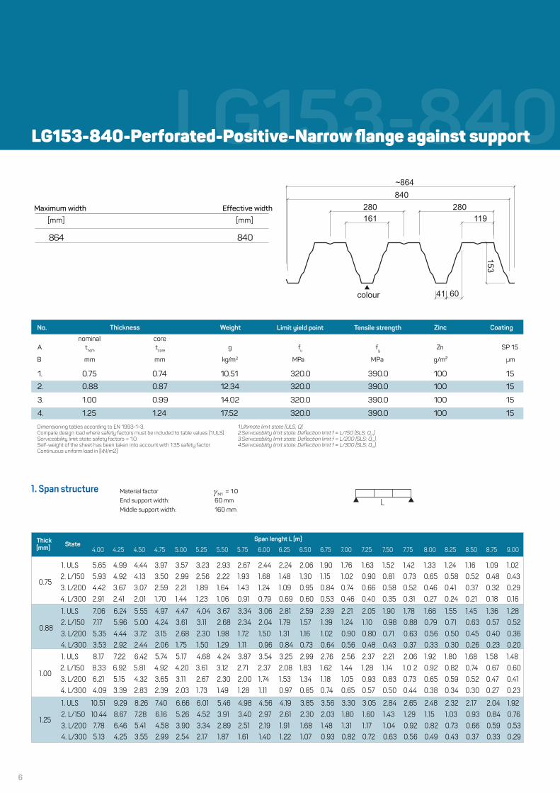
LG153-840LG153-840-Perforated-Positive-Narrow flange against support
4.00 4.25 4.50 4.75 5.00 5.25 5.50 5.75 6.00 6.25 6.50 6.75 7.00 7.25 7.50 7.75 8.00 8.25 8.50 8.75 9.00
A g Zn SP 15
B mm mm kg/m2 g/m² m
1. 0.75 0.74 10.51 100 15
2. 0.88 0.87 12.34 100 15
3. 1.00 0.99 14.02 100 15
4. 1.25 1.24 17.52
f y
MPa
320.0
320.0
320.0
320.0
fu
MPa
390.0
390.0
390.0
390.0 100 15
1. Span structureL
280
119
~864
840
161
280
153
41 60colour
0.75
1. ULS 5.65 4.99 4.44 3.97 3.57 3.23 2.93 2.67 2.44 2.24 2.06 1.90 1.76 1.63 1.52 1.42 1.33 1.24 1.16 1.09 1.02
2. L/150 5.93 4.92 4.13 3.50 2.99 2.56 2.22 1.93 1.68 1.48 1.30 1.15 1.02 0.90 0.81 0.73 0.65 0.58 0.52 0.48 0.43
3. L/200 4.42 3.67 3.07 2.59 2.21 1.89 1.64 1.43 1.24 1.09 0.95 0.84 0.74 0.66 0.58 0.52 0.46 0.41 0.37 0.32 0.29
4. L/300 2.91 2.41 2.01 1.70 1.44 1.23 1.06 0.91 0.79 0.69 0.60 0.53 0.46 0.40 0.35 0.31 0.27 0.24 0.21 0.18 0.16
0.88
1. ULS 7.06 6.24 5.55 4.97 4.47 4.04 3.67 3.34 3.06 2.81 2.59 2.39 2.21 2.05 1.90 1.78 1.66 1.55 1.45 1.36 1.28
2. L/150 7.17 5.96 5.00 4.24 3.61 3.11 2.68 2.34 2.04 1.79 1.57 1.39 1.24 1.10 0.98 0.88 0.79 0.71 0.63 0.57 0.52
3. L/200 5.35 4.44 3.72 3.15 2.68 2.30 1.98 1.72 1.50 1.31 1.16 1.02 0.90 0.80 0.71 0.63 0.56 0.50 0.45 0.40 0.36
4. L/300 3.53 2.92 2.44 2.06 1.75 1.50 1.29 1.11 0.96 0.84 0.73 0.64 0.56 0.48 0.43 0.37 0.33 0.30 0.26 0.23 0.20
1.00
1. ULS 8.17 7.22 6.42 5.74 5.17 4.68 4.24 3.87 3.54 3.25 2.99 2.76 2.56 2.37 2.21 2.06 1.92 1.80 1.68 1.58 1.48
2. L/150 8.33 6.92 5.81 4.92 4.20 3.61 3.12 2.71 2.37 2.08 1.83 1.62 1.44 1.28 1.14 1.0 2 0.92 0.82 0.74 0.67 0.60
3. L/200 6.21 5.15 4.32 3.65 3.11 2.67 2.30 2.00 1.74 1.53 1.34 1.18 1.05 0.93 0.83 0.73 0.65 0.59 0.52 0.47 0.41
4. L/300 4.09 3.39 2.83 2.39 2.03 1.73 1.49 1.28 1.11 0.97 0.85 0.74 0.65 0.57 0.50 0.44 0.38 0.34 0.30 0.27 0.23
1.25
1. ULS 10.51 9.29 8.26 7.40 6.66 6.01 5.46 4.98 4.56 4.19 3.85 3.56 3.30 3.05 2.84 2.65 2.48 2.32 2.17 2.04 1.92
2. L/150 10.44 8.67 7.28 6.16 5.26 4.52 3.91 3.40 2.97 2.61 2.30 2.03 1.80 1.60 1.43 1.29 1.15 1.03 0.93 0.84 0.76
3. L/200 7.78 6.46 5.41 4.58 3.90 3.34 2.89 2.51 2.19 1.91 1.68 1.48 1.31 1.17 1.04 0.92 0.82 0.73 0.66 0.59 0.53
4. L/300 5.13 4.25 3.55 2.99 2.54 2.17 1.87 1.61 1.40 1.22 1.07 0.93 0.82 0.72 0.63 0.56 0.49 0.43 0.37 0.33 0.29
Dimensioning tables according to EN 1993-1-3.Compare design load where safety factors must be included to table values (1.ULS).Serviceability limit state safety factors = 1.0.Self-weight of the sheet has been taken into account with 1.35 safety factorContinuous uniform load in [kN/m2].
1.Ultimate limit state (ULS; Q).2.Serviceability limit state. Deflection limit f = L/150 (SLS; Q ).ch
3.Serviceability limit state. Deflection limit f = L/200 (SLS; Q ).ch
4.Serviceability limit state. Deflection limit f = L/300 (SLS; Q ).ch
No. Thickness Weight Tensile strengthLimit yield point Zinc Coating
coretnom tcore
nominal
Thick[mm] State
Span lenght L [m]
Material factor g = 1.0M1
End support width: 60 mmMiddle support width: 160 mm
Effective widthMaximum width
]mm[]mm[
048468
µ
7
LG153-840
4.00 4.25 4.50 4.75 5.00 5.25 5.50 5.75 6.00 6.25 6.50 6.75 7.00 7.25 7.50 7.75 8.00 8.25 8.50 8.75 9.00
Stare4.00 4.25 4.50 4.75 5.00 5.25 5.50 5.75 6.00 6.25 6.50 6.75 7.00 7.25 7.50 7.75 8.00 8.25 8.50 8.75 9.00
2. Span structure
L L
3. Span structure
L L L
0.752. L/150 11.46 9.53 8.01 6.79 5.81 5.01 4.34 3.79 3.32 2.93 2.59 2.30 2.05 1.84 1.65 1.48 1.34 1.21 1.10 1.00 0.91
3. L/200 8.56 7.12 5.98 5.07 4.33 3.72 3.23 2.81 2.46 2.16 1.91 1.70 1.52 1.36 1.21 1.09 0.98 0.88 0.80 0.73 0.66
4. L/300 5.67 4.71 3.95 3.34 2.85 2.45 2.12 1.85 1.61 1.41 1.24 1.10 0.98 0.86 0.77 0.68 0.62 0.55 0.50 0.45 0.41
1.00
1. ULS 7.40 6.71 6.11 5.58 5.12 4.72 4.36 4.03 3.75 3.49 3.25 3.04 2.85 2.67 2.51 2.37 2.23 2.11 1.99 1.89 1.79
2. L/150 16.07 13.37 11.24 9.54 8.15 7.03 6.09 5.31 4.66 4.11 3.64 3.23 2.8 8 2.58 2.32 2.09 1.89 1.70 1.55 1.41 1.29
3. L/200 12.01 9.99 8.39 7.12 6.08 5.23 4.54 3.95 3.46 3.04 2.69 2.39 2.13 1.90 1.70 1.53 1.38 1.24 1.13 1.02 0.93
4. L/300 7.96 6.62 5.55 4.70 4.01 3.44 2.98 2.59 2.27 1.98 1.75 1.55 1.37 1.22 1.09 0.98 0.87 0.78 0.70 0.63 0.57
1.25
1. ULS 10.55 9.55 8.68 7.92 7.26 6.67 6.16 5.70 5.28 4.91 4.58 4.28 4.01 3.76 3.53 3.32 3.13 2.95 2.79 2.64 2.50
2. L/150 20.16 16.78 14.10 11.96 10.24 8.82 7.64 6.67 5.85 5.16 4.56 4.06 3.62 3.24 2.91 2.62 2.37 2.14 1.94 1.76 1.61
3. L/200 15.08 12.54 10.54 8.93 7.63 6.57 5.69 4.96 4.34 3.82 3.37 3.00 2.67 2.39 2.14 1.92 1.73 1.56 1.41 1.28 1.17
4. L/300 9.99 8.30 6.97 5.89 5.03 4.32 3.73 3.25 2.84 2.49 2.19 1.94 1.73 1.53 1.37 1.22 1.10 0.98 0.89 0.80 0.72
0.75
1. ULS 3.70 3.35 3.05 2.78 2.55 2.35 2.17 2.01 1.86 1.74 1.61 1.50 1.41 1.32 1.24 1.16 1.09 1.03 0.97 0.92 0.87
2. L/150 14.44 12.03 10.11 8.58 7.34 6.33 5.49 4.79 4.21 3.71 3.29 2.93 2.61 2.34 2.10 1.89 1.71 1.55 1.41 1.28 1.17
3. L/200 10.81 8.99 7.56 6.41 5.48 4.72 4.09 3.57 3.13 2.75 2.44 2.16 1.93 1.73 1.56 1.40 1.26 1.14 1.03 0.94 0.86
4. L/300 7.17 5.96 5.00 4.24 3.62 3.11 2.69 2.34 2.05 1.81 1.59 1.41 1.25 1.12 1.00 0.90 0.81 0.73 0.65 0.59 0.53
0.88
1. ULS 4.89 4.42 4.03 3.68 3.37 3.10 2.85 2.64 2.45 2.28 2.12 1.98 1.85 1.73 1.63 1.53 1.44 1.36 1.29 1.22 1.15
2. L/150 17.45 14.53 12.22 10.37 8.87 7.65 6.64 5.79 5.09 4.48 3.98 3.53 3.16 2.83 2.54 2.29 2.08 1.88 1.71 1.55 1.42
3. L/200 13.05 10.87 9.14 7.75 6.62 5.70 4.94 4.31 3.78 3.33 2.95 2.62 2.34 2.09 1.88 1.69 1.52 1.38 1.25 1.14 1.04
4. L/300 8.67 7.20 6.05 5.13 4.38 3.76 3.25 2.83 2.48 2.18 1.93 1.71 1.52 1.36 1.21 1.08 0.98 0.88 0.79 0.72 0.65
1.00
1. ULS 6.13 5.55 5.04 4.60 4.21 3.87 3.57 3.30 3.06 2.85 2.65 2.48 2.31 2.17 2.04 1.92 1.80 1.70 1.60 1.52 1.43
2. L/150 20.24 16.84 14.17 12.02 10.29 8.87 7.70 6.72 5.90 5.20 4.61 4.10 3.66 3.28 2.9 5 2.66 2.41 2.18 1.98 1.81 1.65
3. L/200 15.14 12.60 10.59 8.99 7.68 6.62 5.74 5.00 4.38 3.87 3.42 3.04 2.71 2.43 2.18 1.96 1.77 1.60 1.45 1.32 1.20
4. L/300 10.05 8.35 7.02 5.94 5.08 4.36 3.78 3.29 2.88 2.53 2.24 1.99 1.77 1.57 1.41 1.27 1.13 1.02 0.92 0.83 0.76
1.25
1. ULS 8.71 7.87 7.14 6.51 5.95 5.46 5.03 4.65 4.31 4.00 3.72 3.47 3.25 3.04 2.85 2.67 2.52 2.38 2.24 2.11 2.01
2. L/150 25.41 21.17 17.80 15.11 12.93 11.15 9.67 8.44 7.41 6.53 5.79 5.15 4.60 4.12 3.71 3.34 3.03 2.74 2.49 2.27 2.07
3. L/200 19.01 15.82 13.30 11.29 9.65 8.32 7.21 6.29 5.51 4.86 4.30 3.81 3.41 3.05 2.74 2.46 2.22 2.01 1.82 1.66 1.51
4. L/300 12.62 10.49 8.81 7.47 6.37 5.48 4.75 4.13 3.62 3.18 2.81 2.49 2.22 1.98 1.77 1.59 1.43 1.29 1.16 1.05 0.95
1. ULS 4.99 4.53 4.13 3.78 3.4 7 3.20 2.95 2.74 2.54 2.37 2.21 2.07 1.93 1.82 1.71 1.61 1.52 1.43 1.36 1.29 1.22
0.88
1. ULS 4.99 4.53 4.13 3.78 3.47 3.20 2.95 2.74 2.54 2.37 221 2.07 1.93 1.82 1.71 1.61 1.52 1.43 1.36 1.29 1.22
2. L/150 13.85 11.53 9.68 8.22 7.03 6.05 5.26 4.58 4.02 3.54 3.13 2.78 2.48 2.23 2.00 1.80 1.62 1.47 1.33 1.21 1.10
3. L/200 10.36 8.61 7.23 6.14 5.24 4.51 3.91 3.40 2.98 2.62 2.32 2.06 1.83 1.63 1.47 1.31 1.19 1.07 0.97 0.88 0.80
4. L/300 6.86 5.70 4.78 4.05 3.45 2.96 2.56 2.23 1.95 1.71 1.51 1.33 1.18 1.05 0.94 0.84 0.75 0.68 0.60 0.55 0.49
Material factor g = 1.0M1
End support width: 60 mmMiddle support width: 160 mm
Material factor g = 1.0M1
End support width: 60 mmMiddle support width: 160 mm
Thick[mm]
Span lenght L [m]
Thick[mm] State
Span lenght L [m]
LG153-840-Perforated-Positive-Narrow flange against support
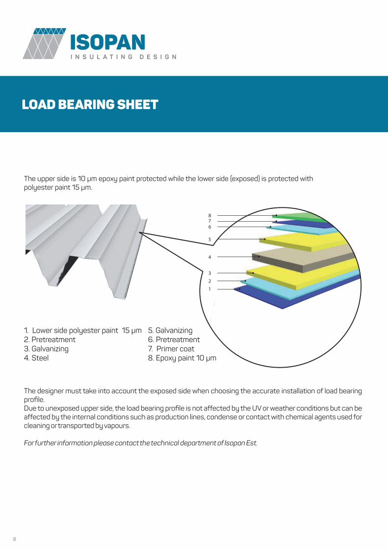
LOAD BEARING SHEET
8
The upper side is 10 µm epoxy paint protected while the lower side (exposed) is protected withpolyester paint 15 µm.
The designer must take into account the exposed side when choosing the accurate installation of load bearing profile.Due to unexposed upper side, the load bearing profile is not affected by the UV or weather conditions but can be affected by the internal conditions such as production lines, condense or contact with chemical agents used for cleaning or transported by vapours.
For further information please contact the technical department of Isopan Est.
1. Lower side polyester paint 15 µm2. Pretreatment3. Galvanizing 4. Steel
5. Galvanizing6. Pretreatment7. Primer coat8. Epoxy paint 10 µm
9
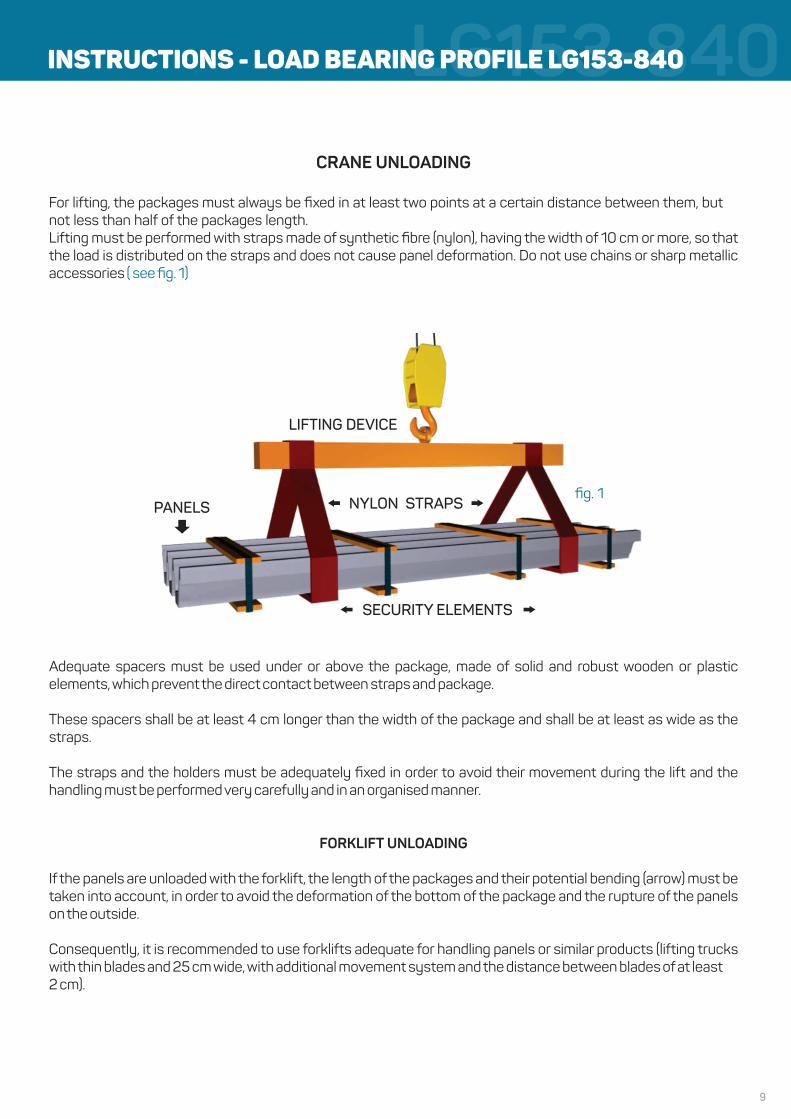
LG153-840CRANE UNLOADING
For lifting, the packages must always be fixed in at least two points at a certain distance between them, but not less than half of the packages length.Lifting must be performed with straps made of synthetic fibre (nylon), having the width of 10 cm or more, so that the load is distributed on the straps and does not cause panel deformation. Do not use chains or sharp metallic accessories ( see fig. 1)
Adequate spacers must be used under or above the package, made of solid and robust wooden or plastic elements, which prevent the direct contact between straps and package.
These spacers shall be at least 4 cm longer than the width of the package and shall be at least as wide as the straps.
The straps and the holders must be adequately fixed in order to avoid their movement during the lift and the handling must be performed very carefully and in an organised manner.
FORKLIFT UNLOADING
If the panels are unloaded with the forklift, the length of the packages and their potential bending (arrow) must be taken into account, in order to avoid the deformation of the bottom of the package and the rupture of the panels on the outside.
Consequently, it is recommended to use forklifts adequate for handling panels or similar products (lifting trucks with thin blades and 25 cm wide, with additional movement system and the distance between blades of at least 2 cm).
INSTRUCTIONS - LOAD BEARING PROFILE LG153-840
fig. 1
LIFTING DEVICE
PANELS NYLON STRAPS
SECURITY ELEMENTS
10
LG153-840STORAGE
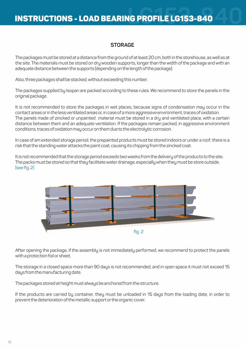
The packages must be stored at a distance from the ground of at least 20 cm, both in the storehouse, as well as at the site. The materials must be stored on dry wooden supports, longer than the width of the package and with an adequate distance between the supports (depending on the length of the package).
Also, three packages shall be stacked, without exceeding this number.
The packages supplied by Isopan are packed according to these rules. We recommend to store the panels in the original package.
It is not recommended to store the packages in wet places, because signs of condensation may occur in the contact areas or in the less ventilated areas or, in case of a more aggressive environment, traces of oxidation.The panels made of zincked or unpainted material must be stored in a dry and ventilated place, with a certain distance between them and an adequate ventilation. If the packages remain packed, in aggressive environment conditions, traces of oxidation may occur on them due to the electrolytic corrosion.
In case of am extended storage period, the prepainted products must be stored indoors or under a roof; there is a risk that the standing water attacks the paint coat, causing its chipping from the zincked coat.
It is not recommended that the storage period exceeds two weeks from the delivery of the products to the site.The packs must be stored so that they facilitate water drainage, especially when they must be store outside.(see fig. 2)
After opening the package, if the assembly is not immediately performed, we recommend to protect the panels with a protection foil or sheet.
The storage in a closed space more than 90 days is not recommended, and in open space it must not exceed 15 days from the manufacturing date.
The packages stored at height must always be anchored from the structure.
If the products are carried by container, they must be unloaded in 15 days from the loading date, in order to prevent the deterioration of the metallic support or the organic cover.
fig. 2
INSTRUCTIONS - LOAD BEARING PROFILE LG153-840

11
LG153-840PANELS HANDLING
The panels must be handled according to the occupational safety standards, using the adequate protection means (gloves, protection clothes, coveralls etc.). The manual handling of a panel must be performed by lifting the panel from the package towards its side, avoiding the contact with the panel underneath. Avoid translation movements in case of a contact between panels (as a result of these movements, the panel surface can be scratched). (see fig. 3)
INSTALLATION
The staff in charge with the panels installation must be qualified and must have the correct technical knowledge in order to perform the mounting operations. Upon the request of the customer, the supplier can provide adequate counselling and instruction for the mounting teams.The staff in charge with the mounting must have adequate equipment, which does not damage the panel.For the cutting operations, at the site, adequate equipment must be used (jigsaw, cutting machine etc.).The use of devices with abrasive discs is not recommended. For panels fixing, we recommend the use of accessories recommended by the supplier. These accessories can be ordered also from Isopan.For screws tightening, we recommend the use of a tool provided with a load limiter, so that the screws will be tightened as much as needed for an optimum fixing of the panels.During panels mounting (especially during roof mounting), it is necessary to mount very carefully all accessories and especially to remove extremely carefully the metallic residues, which, by oxidation, can cause damages to the panels surface.
PREPAINTED STEEL AND THE PANELS MADE FROM IT
For the panels explicitly requested with no protection film, it is necessary to take more strict protection measures for the products and to be more careful when handling and installing them.
MAINTENANCEThe main maintenance activity is the panels cleaning. The surfaces of the panels found visibly dirty during the inspection can be washed with water and soap, using a soft brush. The pressure of the water used during cleaning must not exceed 50 bars. The water jet must not be too close or perpendicular to the surface. Near joints, the water jet must be inclined, so that it does not imperil the panels joint.
The fixing equipment, as well as the gloves must be cleaned, so that they do not damage the panel surface.
ANNUAL CONTROLS OF ISOPAN PANELS
WHAT TO INSPECT CORRECTIVE ACTIONS
Conditions of the painted surfaces Evaluation of the surface statusRepaint if possible
Traces of impacts and scratches Repaint and repair the traces of impacts
ScrewsTake out a screw and check for oxidationTighten the screws, if necessary
Delivery areas, especially in case of accessoriesdirectly exposed to external factors
Control the oxidation levelClean and repaint
Dear customer, please read carefully the handling, storage and installation instructions.Thank you for choosing Isopan products.
fig. 3
INSTRUCTIONS - LOAD BEARING PROFILE LG153-840
ISO
PAN
ES
TEN
- E
ditio
n 0
1/20
17