load feeders, motor starters and soft starters - siemens · 6 load feeders, motor starters and soft...
TRANSCRIPT
Siemens LV 1 T · 2008
6/2 Introduction
3RW Soft Starters6/4 General data6/5 3RW30 for standard applications6/12 3RW40 for standard applications6/26 3RW44 for High-Feature applications6/46 Project planning aids
3RA1 Fuseless Load Feeders6/58 General data
Infeed System6/78 3RV19 infeed system
Direct-On-Line Starters, Reversing Starters, Accessories and Infeed System
6/81 Project planning aids
3RA71 Load Feeders with Safety Integrated
6/87 General data6/89 Project planning aids
AS-Interface Motor Starters and Soft StartersIP65/67 Motor Starters and Load Feeders
6/91 Compact starters (400 V AC)6/97 Motor starters (24 V DC)
IP20 Motor Starters and Load Feeders
6/101 AS-Interface load feeder modules6/104 Direct-on-line starters for
busbar systems6/105 Reversing starters for
busbar systems6/106 Project planning aids
ET 200S Motor Starters6/107 ET 200S motor starters6/114 Power modules for
ET 200S motor starters6/115 Terminal modules for
ET 200S motor starters
ET 200S Safety Motor Starters Solutions local / PROFIsafe
6/118 General data6/119 ET 200S Failsafe motor starters6/121 Safety modules local6/128 Safety modules PROFIsafe
ET 200pro Motor Starters6/133 Standard and High Feature6/136 ET 200pro isolator modules6/137 Safety modules
ECOFAST Motor Starters and Soft Starters
6/139 3RK1 3 ECOFAST motor starters and soft starters
3RE Encapsulated Starters6/143 General data6/148 Project planning aids
Load Feeders, Motor Starters and Soft Starters
6
© Siemens AG 2008
6Load Feeders, Motor Starters and Soft Starters
Introduction
6/2 Siemens LV 1 T · 2008
■ Overview
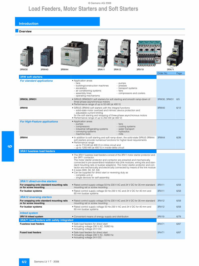
3RW30 3RW40 3RW44 3RA11 3RA12 3RV19 3RA71
Order No. Page
3RW soft startersFor standard applications • Application areas
- fans- building/construction machines- escalators- air conditioning systems- assembly lines- operating mechanisms
- pumps- presses- transport systems- fans- compressors and coolers
3RW30, 3RW31 • SIRIUS 3RW30/31 soft starters for soft starting and smooth ramp-down of three-phase asynchronous motors
• Performance range of up to 55 kW (at 400 V)
3RW30, 3RW31 6/5
3RW40 • SIRIUS 3RW40 soft starters with the integral functions - solid-state motor overload and intrinsic device protection and - adjustable current limitingfor the soft starting and stopping of three-phase asynchronous motors
• Performance range of up to 250 kW (at 400 V)
3RW40 6/12
For High-Feature applications • Application areas- pumps- compressors- industrial refrigerating systems- conveying systems- machine tools
- fans- cooling systems- water transport- hydraulics- mills
3RW44 • In addition to soft starting and soft ramp-down, the solid-state SIRIUS 3RW44 soft starters provide numerous functions for higher-level requirements
• Performance range - up to 710 kW (at 400 V) in inline circuit and - up to 1200 kW (at 400 V) in inside-delta circuit
3RW44 6/26
3RA1 fuseless load feeders• The 3RA1 fuseless load feeders consist of the 3RV1 motor starter protector and
the 3RT1 contactor. The motor starter protector and contactor are prewired and mechanically connected in pre-assembled installation kits (link modules, wiring kits and stan-dard mounting rails or busbar adapters). The motor starter protector and con-tactor are mechanically and electrically connected by means of the link module
• 4 sizes (S00, S0, S2, S3)• Can be supplied for direct start or reversing duty as
- complete unit or - single devices for self-assembly
3RA11 direct-on-line startersFor snapping onto standard mounting rails or for screw mounting
• Rated control supply voltage 50 Hz 230 V AC and 24 V DC for 35 mm standard mounting rail or screw mounting
3RA11 6/58
For busbar systems • Rated control supply voltage 50 Hz 230 V AC and 24 V DC for 40 mm and 60 mm busbar systems
3RA11 6/58
3RA12 reversing startersFor snapping onto standard mounting rails or for screw mounting
• Rated control supply voltage 50 Hz 230 V AC and 24 V DC for 35 mm standard mounting rail or screw mounting
3RA12 6/58
For busbar systems • Rated control supply voltage 50 Hz 230 V AC and 24 V DC for 40 mm and 60 mm busbar systems
3RA12 6/58
Infeed system3RV19 infeed system • Convenient means of energy supply and distribution 3RV19 6/78
3RA71 load feeders with safety integratedFuseless load feeders • Safe load feeders for direct start
• Actuating voltage 230 V AC, 50/60 Hz• Actuating voltage 24 V DC
3RA71 6/87
Fused load feeders • Safe load feeders for direct start• Actuating voltage 230 V AC, 50/60 Hz• Actuating voltage 24 V DC
3RA71 6/87
© Siemens AG 2008
Load Feeders, Motor Starters and Soft Starters
6/3Siemens LV 1 T · 2008
6
Introduction
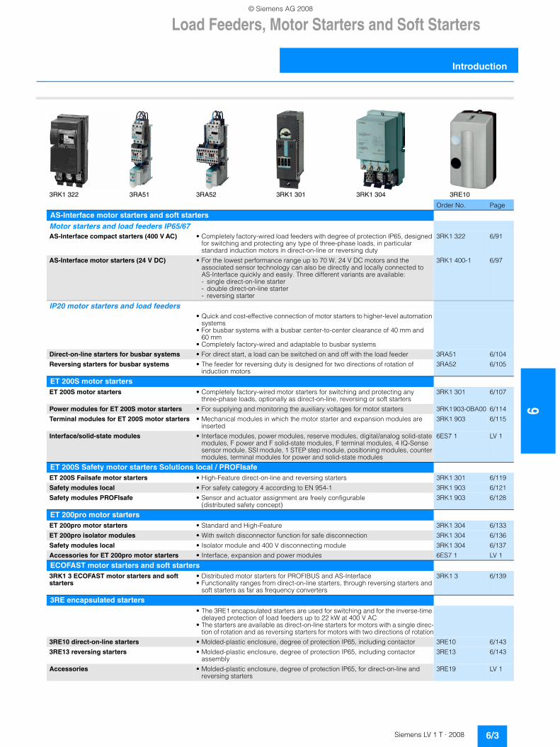
3RK1 322 3RA51 3RA52 3RK1 301 3RK1 304 3RE10
Order No. Page
AS-Interface motor starters and soft startersMotor starters and load feeders IP65/67AS-Interface compact starters (400 V AC) • Completely factory-wired load feeders with degree of protection IP65, designed
for switching and protecting any type of three-phase loads, in particular standard induction motors in direct-on-line or reversing duty
3RK1 322 6/91
AS-Interface motor starters (24 V DC) • For the lowest performance range up to 70 W, 24 V DC motors and the associated sensor technology can also be directly and locally connected to AS-Interface quickly and easily. Three different variants are available:- single direct-on-line starter- double direct-on-line starter- reversing starter
3RK1 400-1 6/97
IP20 motor starters and load feeders• Quick and cost-effective connection of motor starters to higher-level automation
systems• For busbar systems with a busbar center-to-center clearance of 40 mm and
60 mm • Completely factory-wired and adaptable to busbar systems
Direct-on-line starters for busbar systems • For direct start, a load can be switched on and off with the load feeder 3RA51 6/104
Reversing starters for busbar systems • The feeder for reversing duty is designed for two directions of rotation of induction motors
3RA52 6/105
ET 200S motor startersET 200S motor starters • Completely factory-wired motor starters for switching and protecting any
three-phase loads, optionally as direct-on-line, reversing or soft starters3RK1 301 6/107
Power modules for ET 200S motor starters • For supplying and monitoring the auxiliary voltages for motor starters 3RK1 903-0BA00 6/114
Terminal modules for ET 200S motor starters • Mechanical modules in which the motor starter and expansion modules are inserted
3RK1 903 6/115
Interface/solid-state modules • Interface modules, power modules, reserve modules, digital/analog solid-state modules, F power and F solid-state modules, F terminal modules, 4 IQ-Sense sensor module, SSI module, 1 STEP step module, positioning modules, counter modules, terminal modules for power and solid-state modules
6ES7 1 LV 1
ET 200S Safety motor starters Solutions local / PROFIsafeET 200S Failsafe motor starters • High-Feature direct-on-line and reversing starters 3RK1 301 6/119
Safety modules local • For safety category 4 according to EN 954-1 3RK1 903 6/121
Safety modules PROFIsafe • Sensor and actuator assignment are freely configurable (distributed safety concept)
3RK1 903 6/128
ET 200pro motor startersET 200pro motor starters • Standard and High-Feature 3RK1 304 6/133
ET 200pro isolator modules • With switch disconnector function for safe disconnection 3RK1 304 6/136
Safety modules local • Isolator module and 400 V disconnecting module 3RK1 304 6/137
Accessories for ET 200pro motor starters • Interface, expansion and power modules 6ES7 1 LV 1
ECOFAST motor starters and soft starters3RK1 3 ECOFAST motor starters and soft starters
• Distributed motor starters for PROFIBUS and AS-Interface• Functionality ranges from direct-on-line starters, through reversing starters and
soft starters as far as frequency converters
3RK1 3 6/139
3RE encapsulated starters• The 3RE1 encapsulated starters are used for switching and for the inverse-time
delayed protection of load feeders up to 22 kW at 400 V AC• The starters are available as direct-on-line starters for motors with a single direc-
tion of rotation and as reversing starters for motors with two directions of rotation
3RE10 direct-on-line starters • Molded-plastic enclosure, degree of protection IP65, including contactor 3RE10 6/143
3RE13 reversing starters • Molded-plastic enclosure, degree of protection IP65, including contactor assembly
3RE13 6/143
Accessories • Molded-plastic enclosure, degree of protection IP65, for direct-on-line and reversing starters
3RE19 LV 1
© Siemens AG 2008
63RW Soft Starters
General data
6/4 Siemens LV 1 T · 2008
■ Overview
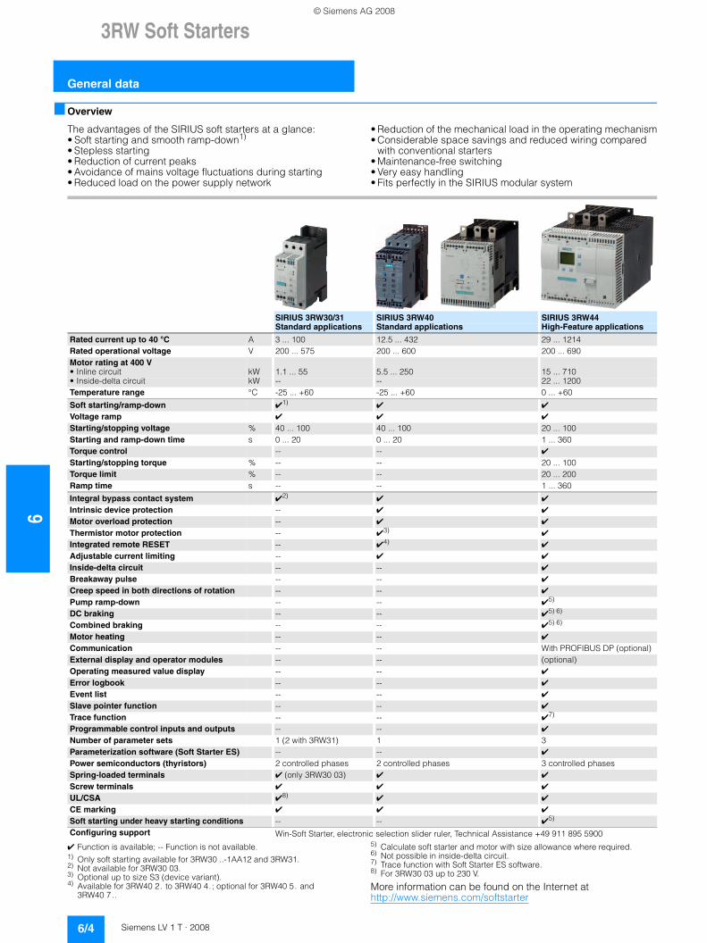
The advantages of the SIRIUS soft starters at a glance:• Soft starting and smooth ramp-down1)
• Stepless starting• Reduction of current peaks• Avoidance of mains voltage fluctuations during starting• Reduced load on the power supply network
• Reduction of the mechanical load in the operating mechanism• Considerable space savings and reduced wiring compared
with conventional starters• Maintenance-free switching• Very easy handling• Fits perfectly in the SIRIUS modular system
✔ Function is available; -- Function is not available.1) Only soft starting available for 3RW30 ..-1AA12 and 3RW31.2) Not available for 3RW30 03.3) Optional up to size S3 (device variant).4) Available for 3RW40 2. to 3RW40 4.; optional for 3RW40 5. and
3RW40 7..
5) Calculate soft starter and motor with size allowance where required.6) Not possible in inside-delta circuit.7) Trace function with Soft Starter ES software.8) For 3RW30 03 up to 230 V.
More information can be found on the Internet at http://www.siemens.com/softstarter
SIRIUS 3RW30/31 SIRIUS 3RW40 SIRIUS 3RW44Standard applications Standard applications High-Feature applications
Rated current up to 40 °C A 3 ... 100 12.5 ... 432 29 ... 1214Rated operational voltage V 200 ... 575 200 ... 600 200 ... 690Motor rating at 400 V• Inline circuit kW 1.1 ... 55 5.5 ... 250 15 ... 710• Inside-delta circuit kW -- -- 22 ... 1200 Temperature range °C -25 ... +60 -25 ... +60 0 ... +60
Soft starting/ramp-down ✔1) ✔ ✔
Voltage ramp ✔ ✔ ✔
Starting/stopping voltage % 40 ... 100 40 ... 100 20 ... 100Starting and ramp-down time s 0 ... 20 0 ... 20 1 ... 360 Torque control -- -- ✔
Starting/stopping torque % -- -- 20 ... 100Torque limit % -- -- 20 ... 200Ramp time s -- -- 1 ... 360
Integral bypass contact system ✔2) ✔ ✔
Intrinsic device protection -- ✔ ✔
Motor overload protection -- ✔ ✔
Thermistor motor protection -- ✔3) ✔
Integrated remote RESET -- ✔4) ✔
Adjustable current limiting -- ✔ ✔
Inside-delta circuit -- -- ✔
Breakaway pulse -- -- ✔
Creep speed in both directions of rotation -- -- ✔
Pump ramp-down -- -- ✔5) DC braking -- -- ✔5) 6) Combined braking -- -- ✔5) 6) Motor heating -- -- ✔
Communication -- -- With PROFIBUS DP (optional)External display and operator modules -- -- (optional)Operating measured value display -- -- ✔
Error logbook -- -- ✔
Event list -- -- ✔
Slave pointer function -- -- ✔
Trace function -- -- ✔7) Programmable control inputs and outputs -- -- ✔
Number of parameter sets 1 (2 with 3RW31) 1 3Parameterization software (Soft Starter ES) -- -- ✔
Power semiconductors (thyristors) 2 controlled phases 2 controlled phases 3 controlled phasesSpring-loaded terminals ✔ (only 3RW30 03) ✔ ✔
Screw terminals ✔ ✔ ✔
UL/CSA ✔8) ✔ ✔
CE marking ✔ ✔ ✔
Soft starting under heavy starting conditions -- -- ✔5) Configuring support Win-Soft Starter, electronic selection slider ruler, Technical Assistance +49 911 895 5900
© Siemens AG 2008
3RW Soft Starters
6/5Siemens LV 1 T · 2008
6
3RW30for standard applications
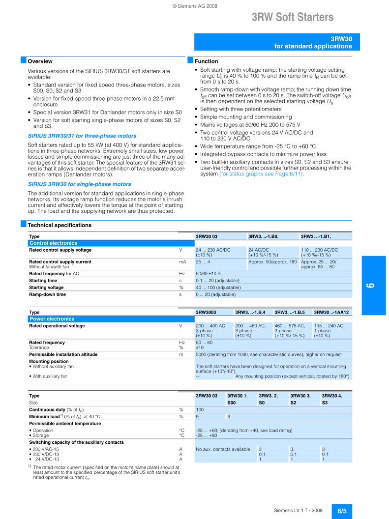
■ Overview
Various versions of the SIRIUS 3RW30/31 soft starters are available:• Standard version for fixed speed three-phase motors, sizes
S00, S0, S2 and S3• Version for fixed-speed three-phase motors in a 22.5 mm
enclosure• Special version 3RW31 for Dahlander motors only in size S0• Version for soft starting single-phase motors of sizes S0, S2
and S3.
SIRIUS 3RW30/31 for three-phase motors
Soft starters rated up to 55 kW (at 400 V) for standard applica-tions in three-phase networks. Extremely small sizes, low power losses and simple commissioning are just three of the many ad-vantages of this soft starter. The special feature of the 3RW31 se-ries is that it allows independent definition of two separate accel-eration ramps (Dahlander motors).
SIRIUS 3RW30 for single-phase motors
The additional version for standard applications in single-phase networks. Its voltage ramp function reduces the motor's inrush current and effectively lowers the torque at the point of starting up. The load and the supplying network are thus protected.
■ Function
• Soft starting with voltage ramp; the starting voltage setting range Us is 40 % to 100 % and the ramp time tR can be set from 0 s to 20 s.
• Smooth ramp-down with voltage ramp; the running down time toff can be set between 0 s to 20 s. The switch-off voltage Uoff is then dependent on the selected starting voltage Us
• Setting with three potentiometers• Simple mounting and commissioning• Mains voltages at 50/60 Hz 200 to 575 V• Two control voltage versions 24 V AC/DC and
110 to 230 V AC/DC• Wide temperature range from -25 °C to +60 °C• Integrated bypass contacts to minimize power loss• Two built-in auxiliary contacts in sizes S0, S2 and S3 ensure
user-friendly control and possible further processing within the system (for status graphs see Page 6/11).
■ Technical specifications
1) The rated motor current (specified on the motor's name plate) should at least amount to the specified percentage of the SIRIUS soft starter unit's rated operational current Ie.
Type 3RW30 03 3RW3. ..-1.B0. 3RW3. ..-1.B1.Control electronics Rated control supply voltage V 24 ... 230 AC/DC
(±10 %)24 AC/DC (+10 %/-15 %)
110 ... 230 AC/DC(+10 %/-15 %)
Rated control supply current Without fan/with fan
mA 25 ... 4 Approx. 50/approx. 180 Approx. 25 ... 20/ approx. 85 ... 80
Rated frequency for AC Hz 50/60 ±10 %
Starting time s 0.1 ... 20 (adjustable)
Starting voltage % 40 ... 100 (adjustable)
Ramp-down time s 0 ... 20 (adjustable)
Type 3RW3003 3RW3. ..-1.B.4 3RW3. ..-1.B.5 3RW30 ..-1AA12Power electronicsRated operational voltage V 200 ... 400 AC,
3-phase (±10 %)
200 ... 460 AC, 3-phase (±10 %)
460 ... 575 AC, 3-phase (+10 %/-15 %)
115 ... 240 AC, 1-phase (±10 %)
Rated frequency Hz 50 ... 60Tolerance % ±10
Permissible installation altitude m 5000 (derating from 1000, see characteristic curves); higher on request
Mounting position• Without auxiliary fan The soft starters have been designed for operation on a vertical mounting
surface (+10°/-10°).• With auxiliary fan -- Any mounting position (except vertical, rotated by 180°)
Type 3RW30 03 3RW30 1. 3RW3. 2. 3RW30 3. 3RW30 4.
Size S00 S0 S2 S3
Continuous duty (% of Ie) % 100
Minimum load1) (% of Ie); at 40 °C % 9 4
Permissible ambient temperature
• Operation °C -25 ... +60; (derating from +40, see load rating)• Storage °C -25 ... +80
Switching capacity of the auxiliary contacts
• 230 V/AC-15 A No aux. contacts available 3 3 3• 230 V/DC-13 A 0.1 0.1 0.1• 24 V/DC-13 A 1 1 1
© Siemens AG 2008
63RW Soft Starters
3RW30 for standard applications
6/6 Siemens LV 1 T · 2008
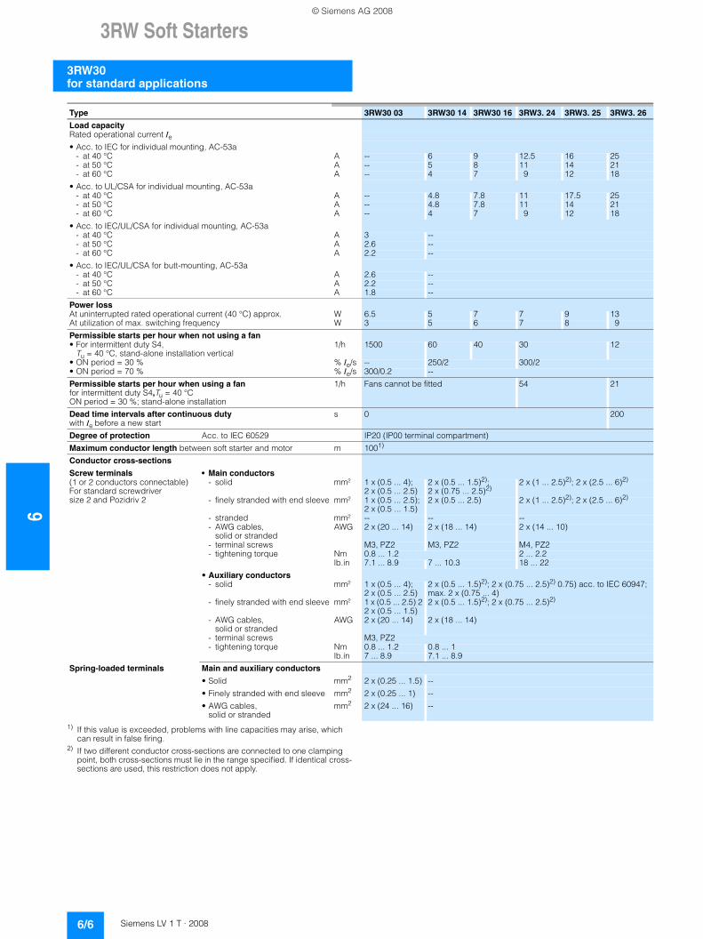
1) If this value is exceeded, problems with line capacities may arise, which can result in false firing.
2) If two different conductor cross-sections are connected to one clamping point, both cross-sections must lie in the range specified. If identical cross-sections are used, this restriction does not apply.
Type 3RW30 03 3RW30 14 3RW30 16 3RW3. 24 3RW3. 25 3RW3. 26
Load capacity Rated operational current Ie• Acc. to IEC for individual mounting, AC-53a
- at 40 °C A -- 6 9 12.5 16 25- at 50 °C A -- 5 8 11 14 21- at 60 °C A -- 4 7 9 12 18
• Acc. to UL/CSA for individual mounting, AC-53a- at 40 °C A -- 4.8 7.8 11 17.5 25- at 50 °C A -- 4.8 7.8 11 14 21- at 60 °C A -- 4 7 9 12 18
• Acc. to IEC/UL/CSA for individual mounting, AC-53a- at 40 °C A 3 --- at 50 °C A 2.6 --- at 60 °C A 2.2 --
• Acc. to IEC/UL/CSA for butt-mounting, AC-53a- at 40 °C A 2.6 --- at 50 °C A 2.2 --- at 60 °C A 1.8 --
Power loss At uninterrupted rated operational current (40 °C) approx. W 6.5 5 7 7 9 13At utilization of max. switching frequency W 3 5 6 7 8 9
Permissible starts per hour when not using a fan • For intermittent duty S4,
Tu = 40 °C, stand-alone installation vertical1/h 1500 60 40 30 12
• ON period = 30 % % Ie/s -- 250/2 300/2• ON period = 70 % % Ie/s 300/0.2 --
Permissible starts per hour when using a fan for intermittent duty S4,Tu = 40 °C ON period = 30 %; stand-alone installation
1/h Fans cannot be fitted 54 21
Dead time intervals after continuous duty with Ie before a new start
s 0 200
Degree of protection Acc. to IEC 60529 IP20 (IP00 terminal compartment)
Maximum conductor length between soft starter and motor m 1001)
Conductor cross-sections
Screw terminals • Main conductors (1 or 2 conductors connectable)For standard screwdriver size 2 and Pozidriv 2
- solid mm² 1 x (0.5 ... 4); 2 x (0.5 ... 2.5)
2 x (0.5 ... 1.5)2); 2 x (0.75 ... 2.5)2)
2 x (1 ... 2.5)2); 2 x (2.5 ... 6)2)
- finely stranded with end sleeve mm² 1 x (0.5 ... 2.5); 2 x (0.5 ... 1.5)
2 x (0.5 ... 2.5) 2 x (1 ... 2.5)2); 2 x (2.5 ... 6)2)
- stranded mm² -- -- --- AWG cables,
solid or strandedAWG 2 x (20 ... 14) 2 x (18 ... 14) 2 x (14 ... 10)
- terminal screws M3, PZ2 M3, PZ2 M4, PZ2- tightening torque Nm 0.8 ... 1.2 2 ... 2.2
lb.in 7.1 ... 8.9 7 ... 10.3 18 ... 22
• Auxiliary conductors - solid mm² 1 x (0.5 ... 4);
2 x (0.5 ... 2.5)2 x (0.5 ... 1.5)2); 2 x (0.75 ... 2.5)2) 0.75) acc. to IEC 60947; max. 2 x (0.75 ... 4)
- finely stranded with end sleeve mm² 1 x (0.5 ... 2.5) 2 2 x (0.5 ... 1.5)
2 x (0.5 ... 1.5)2); 2 x (0.75 ... 2.5)2)
- AWG cables, solid or stranded
AWG 2 x (20 ... 14) 2 x (18 ... 14)
- terminal screws M3, PZ2- tightening torque Nm 0.8 ... 1.2 0.8 ... 1
lb.in 7 ... 8.9 7.1 ... 8.9
Spring-loaded terminals Main and auxiliary conductors
• Solid mm2 2 x (0.25 ... 1.5) --
• Finely stranded with end sleeve mm2 2 x (0.25 ... 1) --
• AWG cables, solid or stranded
mm2 2 x (24 ... 16) --
© Siemens AG 2008
3RW Soft Starters
6/7Siemens LV 1 T · 2008
6
3RW30for standard applications
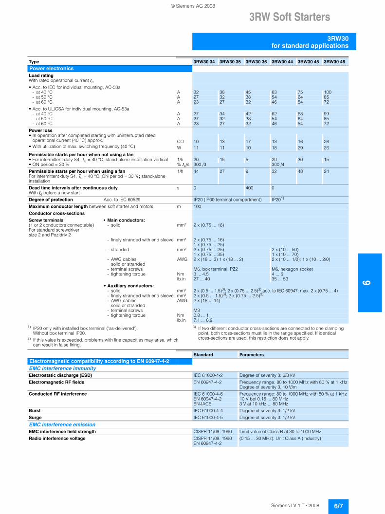
1) IP20 only with installed box terminal ('as-delivered'). Without box terminal IP00.
2) If this value is exceeded, problems with line capacities may arise, which can result in false firing.
3) If two different conductor cross-sections are connected to one clamping point, both cross-sections must lie in the range specified. If identical cross-sections are used, this restriction does not apply.
Type 3RW30 34 3RW30 35 3RW30 36 3RW30 44 3RW30 45 3RW30 46
Power electronicsLoad rating With rated operational current Ie• Acc. to IEC for individual mounting, AC-53a
- at 40 °C A 32 38 45 63 75 100- at 50 °C A 27 32 38 54 64 85- at 60 °C A 23 27 32 46 54 72
• Acc. to UL/CSA for individual mounting, AC-53a- at 40 °C A 27 34 42 62 68 99- at 50 °C A 27 32 38 54 64 85- at 60 °C A 23 27 32 46 54 72
Power loss • In operation after completed starting with uninterrupted rated
operational current (40 °C) approx. CO 10 13 17 13 16 26• With utilization of max. switching frequency (40 °C) W 11 11 10 18 29 26
Permissible starts per hour when not using a fan • For intermittent duty S4, Tu = 40 °C, stand-alone installation vertical 1/h 20 15 5 20 30 15• ON period = 30 % % Ie/s 300 /3 300 /4
Permissible starts per hour when using a fan For intermittent duty S4, Tu = 40 °C, ON period = 30 %; stand-alone installation
1/h 44 27 9 32 48 24
Dead time intervals after continuous duty With Ie before a new start
s 0 400 0
Degree of protection Acc. to IEC 60529 IP20 (IP00 terminal compartment) IP201)
Maximum conductor length between soft starter and motors m 100
Conductor cross-sections
Screw terminals • Main conductors: (1 or 2 conductors connectable)For standard screwdriver size 2 and Pozidriv 2
- solid mm² 2 x (0.75 ... 16)
- finely stranded with end sleeve mm² 2 x (0.75 ... 16) 1 x (0.75 ... 25)
- stranded mm² 2 x (0.75 ... 25) 1 x (0.75 ... 35)
2 x (10 ... 50) 1 x (10 ... 70)
- AWG cables, solid or stranded
AWG 2 x (18 ... 3) 1 x (18 ... 2) 2 x (10 ... 1/0); 1 x (10 ... 2/0)
- terminal screws M6, box terminal, PZ2 M6, hexagon socket- tightening torque Nm 3 ... 4.5 4 ... 6
lb.in 27 ... 40 35 ... 53
• Auxiliary conductors: - solid mm² 2 x (0.5 ... 1.5)3); 2 x (0.75 ... 2.5)3) acc. to IEC 60947; max. 2 x (0.75 ... 4)- finely stranded with end sleeve mm² 2 x (0.5 ... 1.5)3); 2 x (0.75 ... 2.5)3)
- AWG cables, solid or stranded
AWG 2 x (18 ... 14)
- terminal screws M3- tightening torque Nm 0.8 ... 1
lb.in 7.1 ... 8.9
Standard ParametersElectromagnetic compatibility according to EN 60947-4-2EMC interference immunity Electrostatic discharge (ESD) IEC 61000-4-2 Degree of severity 3: 6/8 kV
Electromagnetic RF fields EN 60947-4-2 Frequency range: 80 to 1000 MHz with 80 % at 1 kHzDegree of severity 3, 10 V/m
Conducted RF interference IEC 61000-4-6 Frequency range: 80 to 1000 MHz with 80 % at 1 kHz EN 60947-4-2 10 V bei 0.15 ... 80 MHzSN-IACS 3 V at 10 kHz ... 80 MHz
Burst IEC 61000-4-4 Degree of severity 3: 1/2 kV
Surge IEC 61000-4-5 Degree of severity 3: 1/2 kV
EMC interference emission EMC interference field strength CISPR 11/09. 1990 Limit value of Class B at 30 to 1000 MHz
Radio interference voltage CISPR 11/09. 1990 (0.15 ... 30 MHz): Unit Class A (industry)EN 60947-4-2
© Siemens AG 2008
63RW Soft Starters
3RW30 for standard applications
6/8 Siemens LV 1 T · 2008
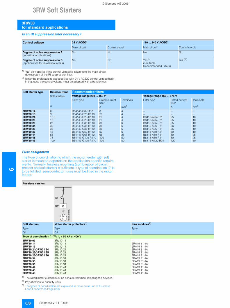
Is an RI suppression filter necessary?
1) "No" only applies if the control voltage is taken from the main circuit downstream of the RI suppression filter.
2) It may be preferable to use a device with 24 V AC/DC control voltage here; in that case the control voltage must be adapted with a transformer.
Fuse assignment
The type of coordination to which the motor feeder with soft starter is mounted depends on the application-specific require-ments. Normally, fuseless mounting (combination of circuit breaker and soft starter) is sufficient. If type of coordination "2" is to be fulfilled, semiconductor fuses must be fitted in the motor feeder.
1) The rated motor current must be considered when selecting the devices.2) Pay attention to quantity units.3) The types of coordination are explained in more detail under "Fuseless
Load Feeders" on Page 6/58.
Control voltage 24 V AC/DC 110 ... 240 V AC/DC
Main circuit Control circuit Main circuit Control circuit
Degree of noise suppression A(industrial applications)
No No No No
Degree of noise suppression B(applications for residential areas)
No No Yes2)
(see table Recommended Filters)
Yes1)2)
Soft starter type Rated current
Soft starters
Recommended filters Voltage range 200 ... 460 V Voltage range 460 ... 575 V
Filter type Rated current filter
TerminalsFilter type Rated current filter
Terminals
A A mm2 A mm2
3RW30 14 6 B84143-G8-R110 8 4 -- -- --3RW30 16 9 B84143-G20-R110 20 4 -- -- --3RW30 24 12.5 B84143-G20-R110 20 4 B8413-A25-R21 25 103RW30 25 16 B84143-G20-R110 20 4 B8413-A25-R21 25 103RW30 26 25 B84143-G36-R110 36 6 B8413-A25-R21 25 103RW30 34 32 B84143-G36-R110 36 6 B8413-A36-R21 36 103RW30 35 38 B84143-G36-R110 36 6 B8413-A36-R21 36 103RW30 36 45 B84143-G50-R110 50 6 B8413-A50-R21 50 103RW30 44 63 B84143-G66-R110 66 25 B8413-A80-R21 80 253RW30 45 75 B84143-G120-R110 120 50 B8413-A80-R21 80 253RW30 46 100 B84143-G120-R110 120 50 B8413-A120-R21 120 50
Fuseless version
Soft starters Motor starter protectors1) Link modules2)
Type Type Type
Q11 Q1
Type of coordination "1"3): Iq = 50 kA at 400 V
3RW30 03 3RV10 11 --3RW30 14 3RV10 11 3RA19 11-1A3RW30 16 3RV10 11 3RA19 11-1A3RW30 24/3RW31 24 3RV10 21 3RA19 21-1A3RW30 25/3RW31 25 3RV10 21 3RA19 21-1A3RW30 26/3RW31 26 3RV10 21 3RA19 21-1A3RW30 34 3RV10 31 3RA19 31-1A3RW30 35 3RV10 31 3RA19 31-1A3RW30 36 3RV10 31 3RA19 31-1A3RW30 44 3RV10 41 3RA19 41-1A3RW30 45 3RV10 41 3RA19 41-1A3RW30 46 3RV10 41 3RA19 41-1A
� � �
����������
� �
� �
© Siemens AG 2008
3RW Soft Starters
6/9Siemens LV 1 T · 2008
6
3RW30for standard applications
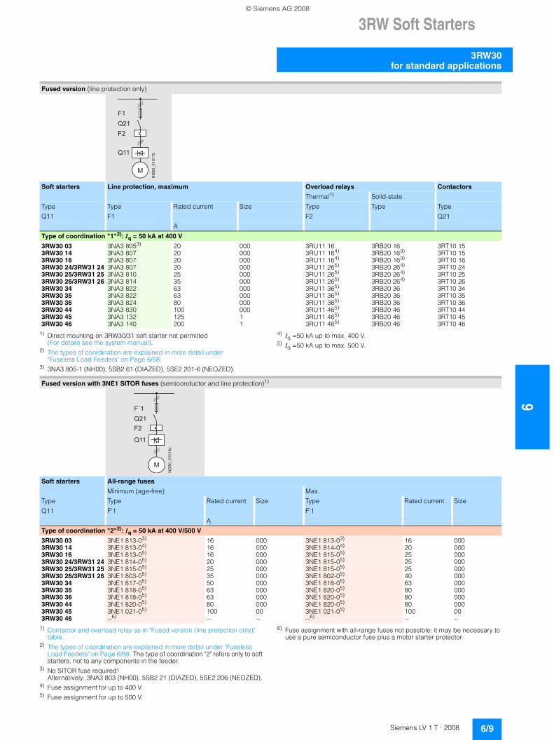
1) Direct mounting on 3RW30/31 soft starter not permitted (For details see the system manual).
2) The types of coordination are explained in more detail under "Fuseless Load Feeders" on Page 6/58.
3) 3NA3 805-1 (NH00), 5SB2 61 (DIAZED), 5SE2 201-6 (NEOZED).
4) Iq =50 kA up to max. 400 V.5) Iq =50 kA up to max. 500 V.
1) Contactor and overload relay as in "Fused version (line protection only)" table.
2) The types of coordination are explained in more detail under "Fuseless Load Feeders" on Page 6/58. The type of coordination "2" refers only to soft starters, not to any components in the feeder.
3) No SITOR fuse required! Alternatively: 3NA3 803 (NH00), 5SB2 21 (DIAZED), 5SE2 206 (NEOZED).
4) Fuse assignment for up to 400 V.5) Fuse assignment for up to 500 V.
6) Fuse assignment with all-range fuses not possible; it may be necessary to use a pure semiconductor fuse plus a motor starter protector.
Fused version (line protection only)
Soft starters Line protection, maximum Overload relays Contactors
Thermal1) Solid-state
Type Type Rated current Size Type Type Type
Q11 F1 F2 Q21
A
Type of coordination "1"2): Iq = 50 kA at 400 V
3RW30 03 3NA3 8053) 20 000 3RU11 16 3RB20 16 3RT10 153RW30 14 3NA3 807 20 000 3RU11 164) 3RB20 163) 3RT10 153RW30 16 3NA3 807 20 000 3RU11 164) 3RB20 163) 3RT10 163RW30 24/3RW31 24 3NA3 807 20 000 3RU11 265) 3RB20 264) 3RT10 243RW30 25/3RW31 25 3NA3 810 25 000 3RU11 265) 3RB20 264) 3RT10 253RW30 26/3RW31 26 3NA3 814 35 000 3RU11 265) 3RB20 264) 3RT10 263RW30 34 3NA3 822 63 000 3RU11 365) 3RB20 36 3RT10 343RW30 35 3NA3 822 63 000 3RU11 365) 3RB20 36 3RT10 353RW30 36 3NA3 824 80 000 3RU11 365) 3RB20 36 3RT10 363RW30 44 3NA3 830 100 000 3RU11 465) 3RB20 46 3RT10 443RW30 45 3NA3 132 125 1 3RU11 465) 3RB20 46 3RT10 453RW30 46 3NA3 140 200 1 3RU11 465) 3RB20 46 3RT10 46
NS
B0_
0101
7bQ11
Q21F1
M
F2
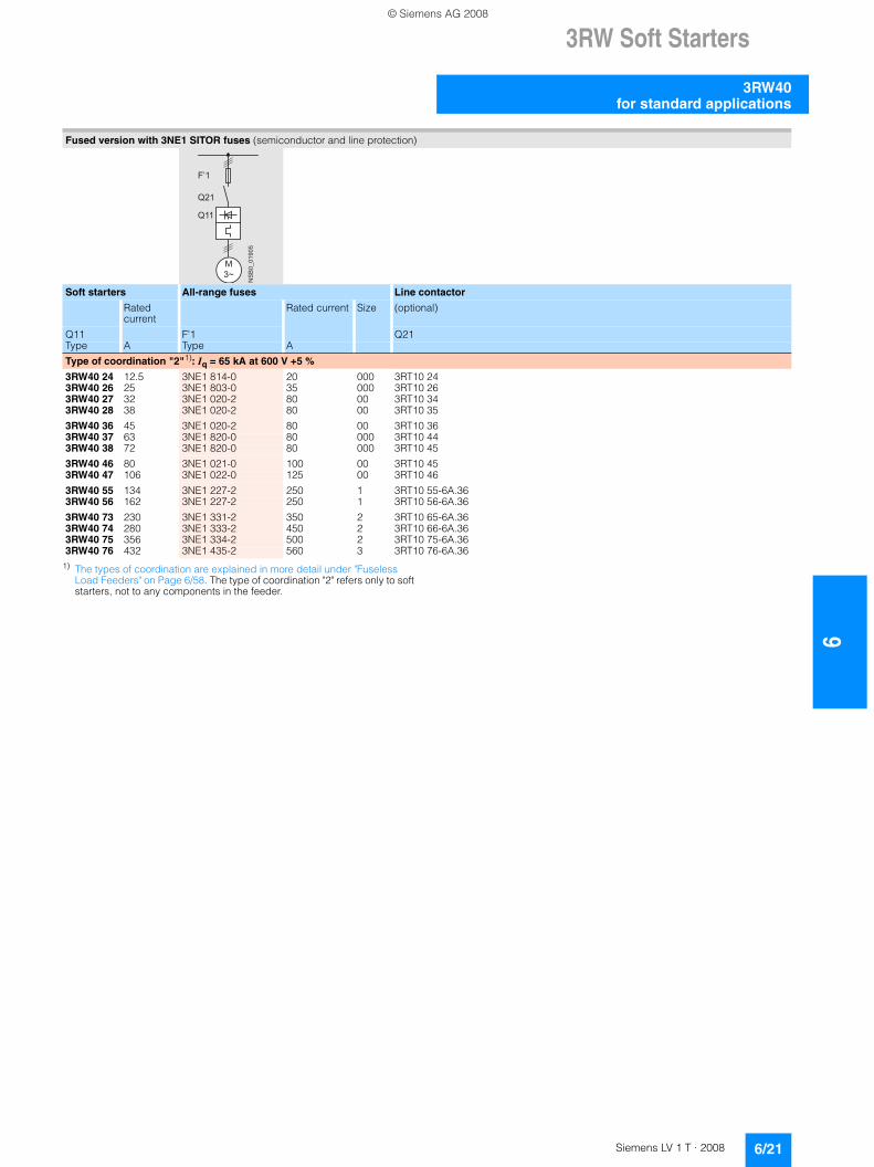
Fused version with 3NE1 SITOR fuses (semiconductor and line protection)1)
Soft starters All-range fuses
Minimum (age-free) Max.
Type Rated current Size Type Rated current SizeType
Q11 F'1 F'1
A
Type of coordination "2"2): Iq = 50 kA at 400 V/500 V
3RW30 03 3NE1 813-03) 16 000 3NE1 813-03) 16 0003RW30 14 3NE1 813-04) 16 000 3NE1 814-04) 20 0003RW30 16 3NE1 813-05) 16 000 3NE1 815-05) 25 0003RW30 24/3RW31 24 3NE1 814-05) 20 000 3NE1 815-05) 25 0003RW30 25/3RW31 25 3NE1 815-05) 25 000 3NE1 815-05) 25 0003RW30 26/3RW31 26 3NE1 803-05) 35 000 3NE1 802-05) 40 0003RW30 34 3NE1 817-05) 50 000 3NE1 818-05) 63 0003RW30 35 3NE1 818-05) 63 000 3NE1 820-05) 80 0003RW30 36 3NE1 818-05) 63 000 3NE1 820-05) 80 0003RW30 44 3NE1 820-05) 80 000 3NE1 820-05) 80 0003RW30 45 3NE1 021-05) 100 00 3NE1 021-05) 100 003RW30 46 --6) -- -- --6) -- --
NS
B0_
0101
8c
Q11
Q21F´1
M
F2
© Siemens AG 2008
63RW Soft Starters
3RW30 for standard applications
6/10 Siemens LV 1 T · 2008
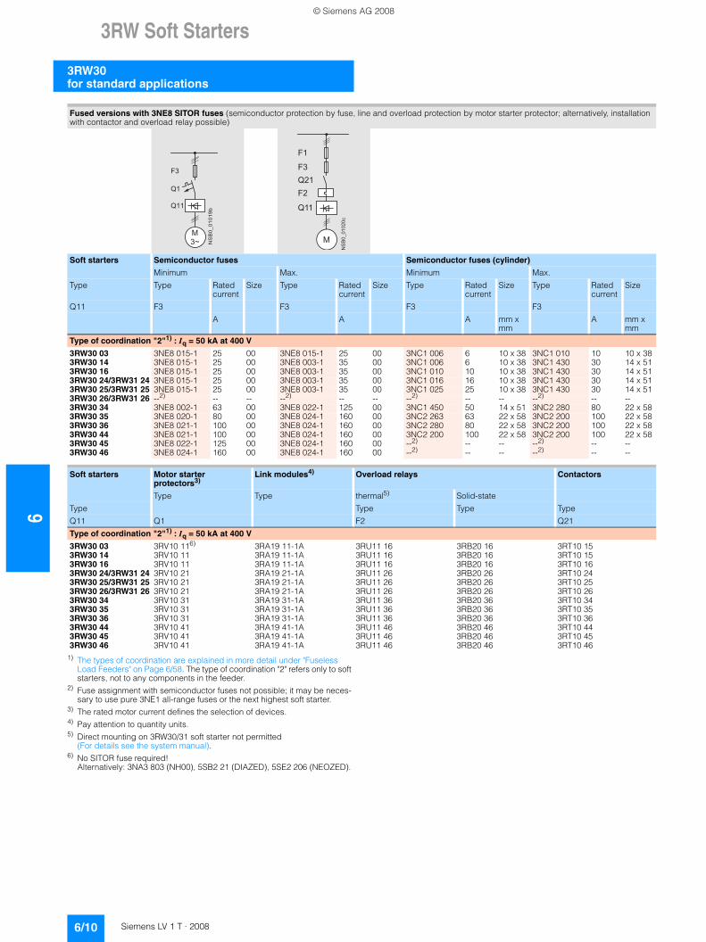
1) The types of coordination are explained in more detail under "Fuseless Load Feeders" on Page 6/58. The type of coordination "2" refers only to soft starters, not to any components in the feeder.
2) Fuse assignment with semiconductor fuses not possible; it may be neces-sary to use pure 3NE1 all-range fuses or the next highest soft starter.
3) The rated motor current defines the selection of devices.4) Pay attention to quantity units.5) Direct mounting on 3RW30/31 soft starter not permitted
(For details see the system manual).6) No SITOR fuse required!
Alternatively: 3NA3 803 (NH00), 5SB2 21 (DIAZED), 5SE2 206 (NEOZED).
Fused versions with 3NE8 SITOR fuses (semiconductor protection by fuse, line and overload protection by motor starter protector; alternatively, installation with contactor and overload relay possible)
Soft starters Semiconductor fuses Semiconductor fuses (cylinder)
Minimum Max. Minimum Max.
Type Rated current
Size Type Rated current
Size Type Rated current
Size Type Rated current
SizeType
Q11 F3 F3 F3 F3
A A A mm x mm
A mm x mm
Type of coordination "2"1) : Iq = 50 kA at 400 V
3RW30 03 3NE8 015-1 25 00 3NE8 015-1 25 00 3NC1 006 6 10 x 38 3NC1 010 10 10 x 383RW30 14 3NE8 015-1 25 00 3NE8 003-1 35 00 3NC1 006 6 10 x 38 3NC1 430 30 14 x 513RW30 16 3NE8 015-1 25 00 3NE8 003-1 35 00 3NC1 010 10 10 x 38 3NC1 430 30 14 x 513RW30 24/3RW31 24 3NE8 015-1 25 00 3NE8 003-1 35 00 3NC1 016 16 10 x 38 3NC1 430 30 14 x 513RW30 25/3RW31 25 3NE8 015-1 25 00 3NE8 003-1 35 00 3NC1 025 25 10 x 38 3NC1 430 30 14 x 513RW30 26/3RW31 26 --2) -- -- --2) -- -- --2) -- -- --2) -- --3RW30 34 3NE8 002-1 63 00 3NE8 022-1 125 00 3NC1 450 50 14 x 51 3NC2 280 80 22 x 583RW30 35 3NE8 020-1 80 00 3NE8 024-1 160 00 3NC2 263 63 22 x 58 3NC2 200 100 22 x 583RW30 36 3NE8 021-1 100 00 3NE8 024-1 160 00 3NC2 280 80 22 x 58 3NC2 200 100 22 x 583RW30 44 3NE8 021-1 100 00 3NE8 024-1 160 00 3NC2 200 100 22 x 58 3NC2 200 100 22 x 583RW30 45 3NE8 022-1 125 00 3NE8 024-1 160 00 --2) -- -- --2) -- --3RW30 46 3NE8 024-1 160 00 3NE8 024-1 160 00 --2) -- -- --2) -- --
Soft starters Motor starter protectors3)
Link modules4) Overload relays Contactors
Type Type thermal5) Solid-state
Type Type Type Type
Q11 Q1 F2 Q21
Type of coordination "2"1) : Iq = 50 kA at 400 V
3RW30 03 3RV10 116) 3RA19 11-1A 3RU11 16 3RB20 16 3RT10 153RW30 14 3RV10 11 3RA19 11-1A 3RU11 16 3RB20 16 3RT10 153RW30 16 3RV10 11 3RA19 11-1A 3RU11 16 3RB20 16 3RT10 163RW30 24/3RW31 24 3RV10 21 3RA19 21-1A 3RU11 26 3RB20 26 3RT10 243RW30 25/3RW31 25 3RV10 21 3RA19 21-1A 3RU11 26 3RB20 26 3RT10 253RW30 26/3RW31 26 3RV10 21 3RA19 21-1A 3RU11 26 3RB20 26 3RT10 263RW30 34 3RV10 31 3RA19 31-1A 3RU11 36 3RB20 36 3RT10 343RW30 35 3RV10 31 3RA19 31-1A 3RU11 36 3RB20 36 3RT10 353RW30 36 3RV10 31 3RA19 31-1A 3RU11 36 3RB20 36 3RT10 363RW30 44 3RV10 41 3RA19 41-1A 3RU11 46 3RB20 46 3RT10 443RW30 45 3RV10 41 3RA19 41-1A 3RU11 46 3RB20 46 3RT10 453RW30 46 3RV10 41 3RA19 41-1A 3RU11 46 3RB20 46 3RT10 46
�
����������
� � �
� �
� �
NS
B0_
0102
0c
Q11
Q21
F1
M
F2
F3
© Siemens AG 2008
3RW Soft Starters
6/11Siemens LV 1 T · 2008
6
3RW30for standard applications
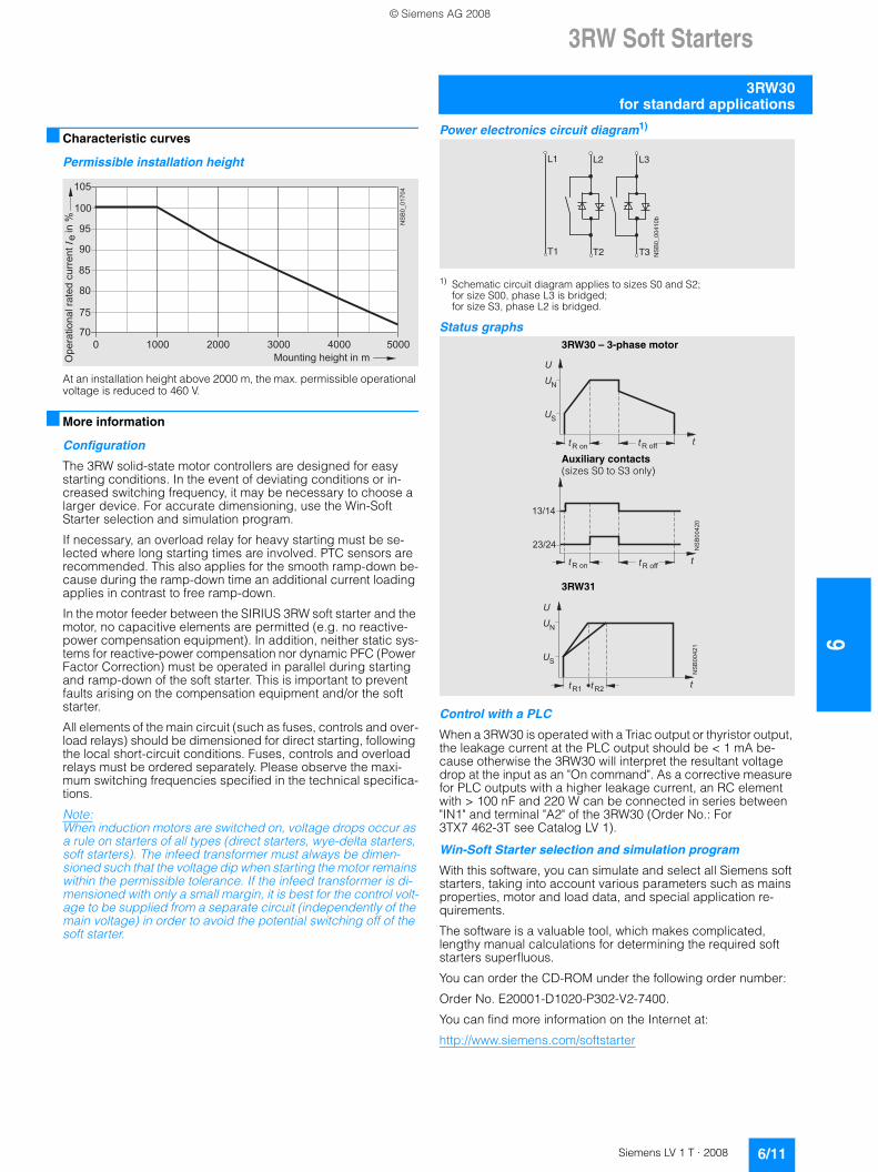
■ Characteristic curves
Permissible installation height
At an installation height above 2000 m, the max. permissible operational voltage is reduced to 460 V.
■ More information
Configuration
The 3RW solid-state motor controllers are designed for easy starting conditions. In the event of deviating conditions or in-creased switching frequency, it may be necessary to choose a larger device. For accurate dimensioning, use the Win-Soft Starter selection and simulation program.
If necessary, an overload relay for heavy starting must be se-lected where long starting times are involved. PTC sensors are recommended. This also applies for the smooth ramp-down be-cause during the ramp-down time an additional current loading applies in contrast to free ramp-down.
In the motor feeder between the SIRIUS 3RW soft starter and the motor, no capacitive elements are permitted (e.g. no reactive-power compensation equipment). In addition, neither static sys-tems for reactive-power compensation nor dynamic PFC (Power Factor Correction) must be operated in parallel during starting and ramp-down of the soft starter. This is important to prevent faults arising on the compensation equipment and/or the soft starter.
All elements of the main circuit (such as fuses, controls and over-load relays) should be dimensioned for direct starting, following the local short-circuit conditions. Fuses, controls and overload relays must be ordered separately. Please observe the maxi-mum switching frequencies specified in the technical specifica-tions.
Note:When induction motors are switched on, voltage drops occur as a rule on starters of all types (direct starters, wye-delta starters, soft starters). The infeed transformer must always be dimen-sioned such that the voltage dip when starting the motor remains within the permissible tolerance. If the infeed transformer is di-mensioned with only a small margin, it is best for the control volt-age to be supplied from a separate circuit (independently of the main voltage) in order to avoid the potential switching off of the soft starter.
Power electronics circuit diagram1)
1) Schematic circuit diagram applies to sizes S0 and S2; for size S00, phase L3 is bridged; for size S3, phase L2 is bridged.
Status graphs
Control with a PLC
When a 3RW30 is operated with a Triac output or thyristor output, the leakage current at the PLC output should be < 1 mA be-cause otherwise the 3RW30 will interpret the resultant voltage drop at the input as an "On command". As a corrective measure for PLC outputs with a higher leakage current, an RC element with > 100 nF and 220 W can be connected in series between "IN1" and terminal "A2" of the 3RW30 (Order No.: For 3TX7 462-3T see Catalog LV 1).
Win-Soft Starter selection and simulation program
With this software, you can simulate and select all Siemens soft starters, taking into account various parameters such as mains properties, motor and load data, and special application re-quirements.
The software is a valuable tool, which makes complicated, lengthy manual calculations for determining the required soft starters superfluous.
You can order the CD-ROM under the following order number:
Order No. E20001-D1020-P302-V2-7400.
You can find more information on the Internet at:
http://www.siemens.com/softstarter
85
105
70
75
80
90
95
100
NS
B0_
0170
4
0 1000 2000 3000 4000 5000
Ope
ratio
nal r
ated
cur
rent
I i
n %
Mounting height in m
e
L1
NS
B0_
0041
0b
L2 L3
T1 T2 T3
�
�
��
��
����� ������
��
�
�
�
�� �
����� ������
�� �
Auxiliary contacts (sizes S0 to S3 only)
�
�
��
��
��� ����
��
��
3RW30 – 3-phase motor
3RW31
© Siemens AG 2008
63RW Soft Starters
3RW40 for standard applications
6/12 Siemens LV 1 T · 2008
■ Overview
SIRIUS 3RW40 soft starters offer all the same advantages as the 3RW30 soft starters. This also applies to the integrated bypass contact system. At the same time they come with additional functions, e.g. solid-state motor overload and intrinsic device protection and adjustable current limiting, optional thermistor motor protection (up to size S3), integrated remote RESET (up to size S3), as well as a two-phase control method (Polarity Balancing) that is unique in this performance range.SIRIUS 3RW40 soft starters are part of the SIRIUS modular sys-tem. This results in advantages such as identical sizes and a uni-form connection method. Thanks to their particularly compact design, SIRIUS 3RW40 soft starters are only half as big as com-parable wye-delta starters. Hence they can be mounted in min-imum space in the control cabinet. Configuring and mounting are carried out quickly and easily thanks to the 3-wire connection.
SIRIUS 3RW40 for three-phase motorsSoft starters rated up to 250 kW (at 400 V) for standard applica-tions in three-phase networks. Extremely small sizes, low power losses and simple commissioning are just three of the many ad-vantages of the SIRIUS 3RW40 soft starters.
■ Function
SIRIUS 3RW40 soft starters have all the same advantages as the 3RW30/31 soft starters. At the same time they come with addi-tional functions and a two-phase control method (Polarity Balancing) that is unique in the performance range up to 250 kW. Starting voltage, starting and ramp-down time of the voltage ramp and current limit are all easy to set using stepless rotary potentiometers, the same as on the SIRIUS 3RW30/31. The rated motor current, the setting of the tripping time and the resetting of the motor overload function are controlled like the SIRIUS overload relays by means of potentiometers and keys. Once again there is nothing new to get used to.
SIRIUS 3RW40 comes with the new, patented control method called "Polarity Balancing", which is designed to prevent direct current components in two-phase controlled soft starters. On two-phase controlled soft starters the current resulting from su-perimposition of the two controlled phases flows in the uncon-trolled phase. This results for physical reasons in an asymmetric distribution of the three phase currents during the starting oper-ation of the motor. This phenomenon cannot be influenced, but in most applications it is non-critical. Controlling the power semi-conductors in the two controlled phases results not only in this asymmetry, however, but also in the previously mentioned direct current components which can cause severe noise generation on the motor at starting voltages of less than 50 %. "Polarity Balancing" reliably eliminates these direct current components during the ramp-up phase. It creates a motor ramp-up that is uni-form in speed, torque and current rise. At the same time the acoustic quality of the starting operation comes close to the quality of a three-phase controlled starting operation. This is made possible by the on-going dynamic balancing of current half-waves of different polarity during the motor ramp-up.
The SIRIUS 3RW40 is equipped with optimum functionality. An integral bypass contact system reduces the power loss of the soft starter during operation. This reliably prevents heating of the switchgear environment. Using a 4-step rotary potentiometer it is possible to set different overload tripping times. Thanks to the in-tegral motor overload protection to IEC 60947-4-2 there is no need of an additional overload relay. Device variants with inte-grated thermistor motor protection (PTC type A of Thermoclick) are available as an option for the sizes S0 to S3. This saves space in the control cabinet and wiring outlay in the feeder. Internal intrinsic device protection prevents in addition the ther-mal overloading of the thyristors and the power section defects this can cause.
As an option the thyristors can also be protected by SITOR semi-conductor fuses from short-circuiting so that the soft starter is still functional after a short-circuit (coordination type 2). And even inrush current peaks are reliably avoided thanks to adjust-able current limiting. Three LEDs are used to indicate the oper-ating state as well as possible errors, e.g. non-permissible trip-ping time (CLASS setting), mains or phase failure, missing load, thermal overloading or device faults.
We offer a comprehensive range of accessories for our soft start-ers. Examples include box terminal blocks, accessories for me-chanical reset and a module for remote reset (size S6 or larger) or a sealing cover or easy-to-fit terminal covers for optimum touch protection.• Soft starting with voltage ramp; the starting voltage setting
range Us is 40 to 100 % and the ramp time tR can be set from 0 to 20 s.
• Smooth ramp-down with voltage ramp; the running down time toff can be set between 0 s to 20 s. The switch-off voltage Uoff is then dependent on the selected starting voltage Us.
• Solid-state motor overload and intrinsic device protection• Optional thermistor motor protection (up to size S3)• Remote reset (integrated up to size S3, optional for size S6 and
larger)• Adjustable current limiting• Integrated bypass contact system to minimize power loss• Setting with potentiometers• Simple mounting and commissioning• Integrated status monitoring and fault monitoring• Mains voltages 50/60 Hz, 200 to 600 V• Various control voltage versions
- sizes S0 to S3:24 V AC/DC and 110 ... 230 V AC/DC
- sizes S6 to S12: 115 V AC and 230 V AC. Control by way of the internal 24 V DC supply and direct control by means of PLC possible.
• Wide temperature range from -25 to +60 °C• Built-in auxiliary contacts ensure user-friendly control and
possible further processing within the system (for status graphs see Page 6/25)
© Siemens AG 2008
3RW Soft Starters
6/13Siemens LV 1 T · 2008
6
3RW40for standard applications
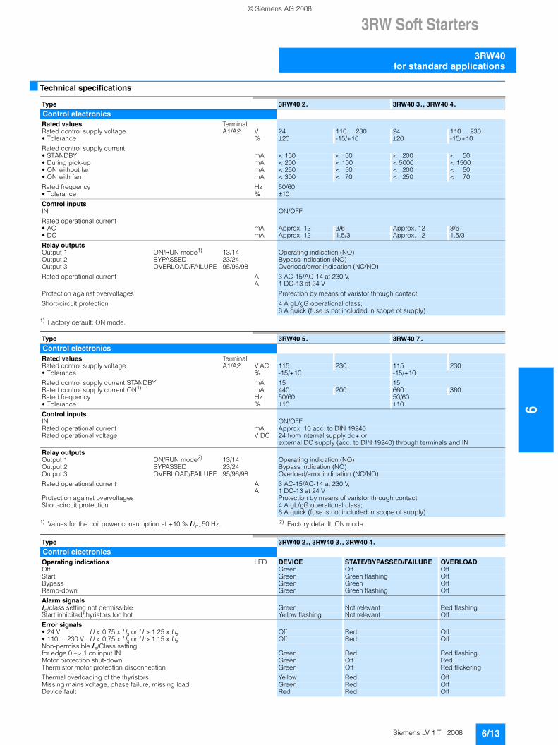
■ Technical specifications
1) Factory default: ON mode.
1) Values for the coil power consumption at +10 % Un, 50 Hz. 2) Factory default: ON mode.
Type 3RW40 2. 3RW40 3., 3RW40 4.
Control electronicsRated values TerminalRated control supply voltage A1/A2 V 24 110 ... 230 24 110 ... 230• Tolerance % ±20 -15/+10 ±20 -15/+10
Rated control supply current • STANDBY mA < 150 < 50 < 200 < 50• During pick-up mA < 200 < 100 < 5000 < 1500• ON without fan mA < 250 < 50 < 200 < 50• ON with fan mA < 300 < 70 < 250 < 70
Rated frequency Hz 50/60• Tolerance % ±10
Control inputsIN ON/OFF
Rated operational current• AC mA Approx. 12 3/6 Approx. 12 3/6• DC mA Approx. 12 1.5/3 Approx. 12 1.5/3
Relay outputsOutput 1 ON/RUN mode1) 13/14 Operating indication (NO)Output 2 BYPASSED 23/24 Bypass indication (NO)Output 3 OVERLOAD/FAILURE 95/96/98 Overload/error indication (NC/NO)
Rated operational current A 3 AC-15/AC-14 at 230 V, A 1 DC-13 at 24 V
Protection against overvoltages Protection by means of varistor through contact
Short-circuit protection 4 A gL/gG operational class;6 A quick (fuse is not included in scope of supply)
Type 3RW40 5. 3RW40 7 .
Control electronicsRated values TerminalRated control supply voltage A1/A2 V AC 115 230 115 230• Tolerance % -15/+10 -15/+10
Rated control supply current STANDBY mA 15 15Rated control supply current ON1) mA 440 200 660 360Rated frequency Hz 50/60 50/60• Tolerance % ±10 ±10
Control inputsIN ON/OFFRated operational current mA Approx. 10 acc. to DIN 19240Rated operational voltage V DC 24 from internal supply dc+ or
external DC supply (acc. to DIN 19240) through terminals and IN
Relay outputsOutput 1 ON/RUN mode2) 13/14 Operating indication (NO)Output 2 BYPASSED 23/24 Bypass indication (NO)Output 3 OVERLOAD/FAILURE 95/96/98 Overload/error indication (NC/NO)
Rated operational current AA
3 AC-15/AC-14 at 230 V, 1 DC-13 at 24 V
Protection against overvoltages Protection by means of varistor through contactShort-circuit protection 4 A gL/gG operational class;
6 A quick (fuse is not included in scope of supply)
Type 3RW40 2., 3RW40 3., 3RW40 4.
Control electronicsOperating indications LED DEVICE STATE/BYPASSED/FAILURE OVERLOADOff Green Off OffStart Green Green flashing OffBypass Green Green OffRamp-down Green Green flashing Off
Alarm signalsIe/class setting not permissible Green Not relevant Red flashingStart inhibited/thyristors too hot Yellow flashing Not relevant Off
Error signals• 24 V: U < 0.75 x Us or U > 1.25 x Us Off Red Off• 110 ... 230 V: U < 0.75 x Us or U > 1.15 x Us Off Red OffNon-permissible Ie/Class setting for edge 0 –> 1 on input IN Green Red Red flashingMotor protection shut-down Green Off RedThermistor motor protection disconnection Green Off Red flickering
Thermal overloading of the thyristors Yellow Red OffMissing mains voltage, phase failure, missing load Green Red OffDevice fault Red Red Off
© Siemens AG 2008
63RW Soft Starters
3RW40 for standard applications
6/14 Siemens LV 1 T · 2008
1) Optional up to size S3 (device variant).2) Integrated remote reset (REMOTE) available only for 3RW40 2.
to 3RW40 4.; remote reset with 3RU19 accessory module available for 3RW40 5. and 3RW40 7..
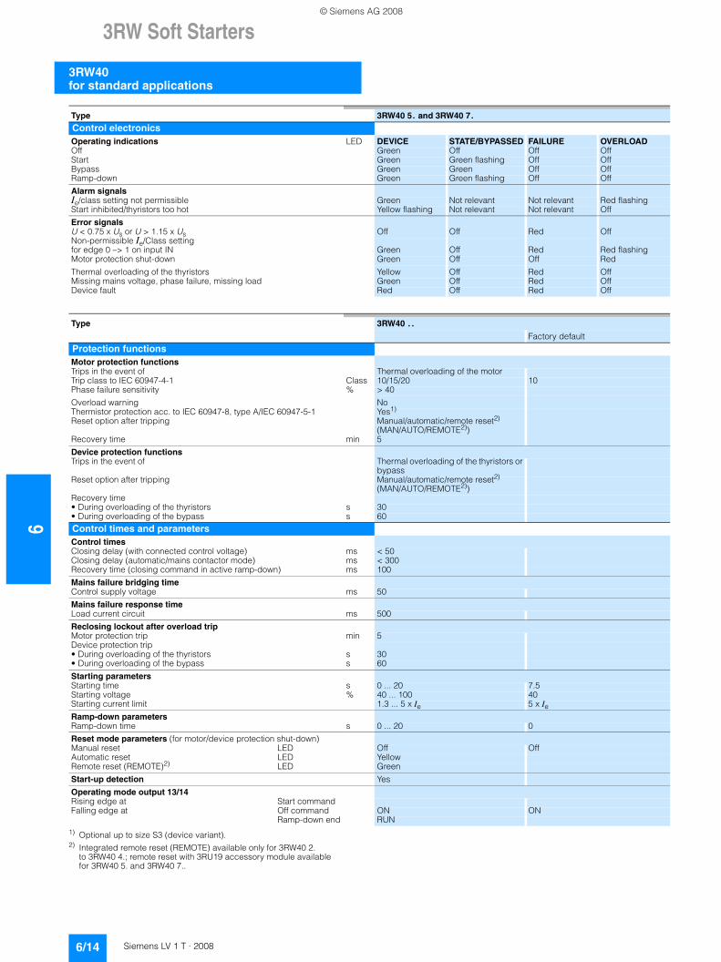
Type 3RW40 5. and 3RW40 7.
Control electronicsOperating indications LED DEVICE STATE/BYPASSED FAILURE OVERLOADOff Green Off Off OffStart Green Green flashing Off OffBypass Green Green Off OffRamp-down Green Green flashing Off Off
Alarm signalsIe/class setting not permissible Green Not relevant Not relevant Red flashingStart inhibited/thyristors too hot Yellow flashing Not relevant Not relevant Off
Error signalsU < 0.75 x Us or U > 1.15 x Us Off Off Red OffNon-permissible Ie/Class setting for edge 0 –> 1 on input IN Green Off Red Red flashingMotor protection shut-down Green Off Off Red
Thermal overloading of the thyristors Yellow Off Red OffMissing mains voltage, phase failure, missing load Green Off Red OffDevice fault Red Off Red Off
Type 3RW40 . .
Factory default
Protection functionsMotor protection functionsTrips in the event of Thermal overloading of the motorTrip class to IEC 60947-4-1 Class 10/15/20 10Phase failure sensitivity % > 40
Overload warning NoThermistor protection acc. to IEC 60947-8, type A/IEC 60947-5-1 Yes1)
Reset option after tripping Manual/automatic/remote reset2) (MAN/AUTO/REMOTE2))
Recovery time min 5
Device protection functionsTrips in the event of Thermal overloading of the thyristors or
bypassReset option after tripping Manual/automatic/remote reset2)
(MAN/AUTO/REMOTE2))Recovery time• During overloading of the thyristors s 30• During overloading of the bypass s 60
Control times and parametersControl timesClosing delay (with connected control voltage) ms < 50Closing delay (automatic/mains contactor mode) ms < 300Recovery time (closing command in active ramp-down) ms 100
Mains failure bridging timeControl supply voltage ms 50
Mains failure response timeLoad current circuit ms 500
Reclosing lockout after overload tripMotor protection trip min 5Device protection trip• During overloading of the thyristors s 30• During overloading of the bypass s 60
Starting parametersStarting time s 0 ... 20 7.5Starting voltage % 40 ... 100 40Starting current limit 1.3 ... 5 x Ie 5 x IeRamp-down parametersRamp-down time s 0 ... 20 0
Reset mode parameters (for motor/device protection shut-down)Manual reset LED Off OffAutomatic reset LED YellowRemote reset (REMOTE)2) LED Green
Start-up detection Yes
Operating mode output 13/14Rising edge at Start commandFalling edge at Off command ON ON
Ramp-down end RUN
© Siemens AG 2008
3RW Soft Starters
6/15Siemens LV 1 T · 2008
6
3RW40for standard applications
1) Measurement at 60 °C according to UL/CSA not required.2) Current limit on soft starter set to 300 % IM.3) For intermittent duty S4 with ON period = 30 %, Tu = 40 °C, stand-alone
installation vertical. The quoted switching frequencies do not apply for automatic mode.
4) Maximum adjustable rated motor current IM, dependent on CLASS setting.
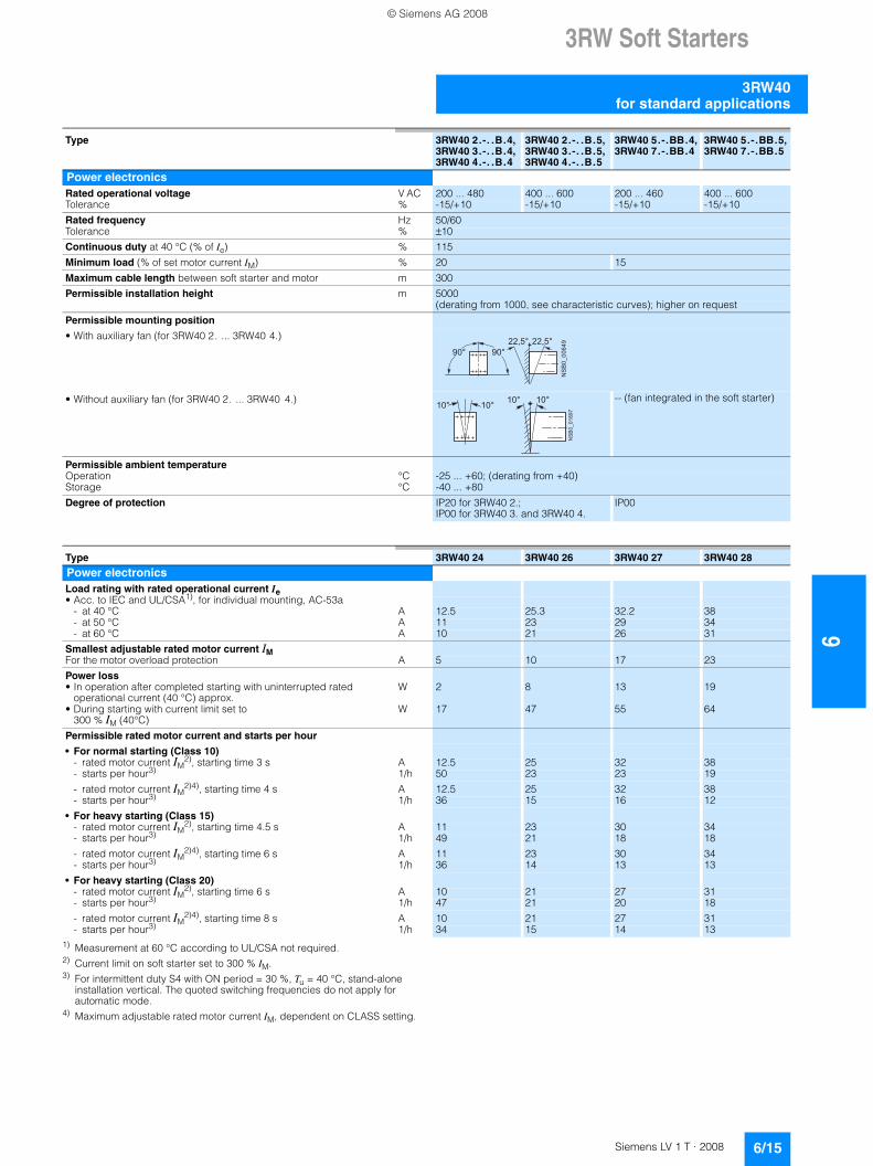
Type 3RW40 2.-. .B.4, 3RW40 3.-. .B.4, 3RW40 4.-. .B.4
3RW40 2.-. .B.5, 3RW40 3.-. .B.5, 3RW40 4.-. .B.5
3RW40 5.-.BB.4, 3RW40 7.-.BB.4
3RW40 5.-.BB.5, 3RW40 7.-.BB.5
Power electronicsRated operational voltage V AC 200 ... 480 400 ... 600 200 ... 460 400 ... 600Tolerance % -15/+10 -15/+10 -15/+10 -15/+10
Rated frequency Hz 50/60Tolerance % ±10
Continuous duty at 40 °C (% of Ie) % 115
Minimum load (% of set motor current IM) % 20 15
Maximum cable length between soft starter and motor m 300
Permissible installation height m 5000(derating from 1000, see characteristic curves); higher on request
Permissible mounting position
• With auxiliary fan (for 3RW40 2. ... 3RW40 4.)
• Without auxiliary fan (for 3RW40 2. ... 3RW40 4.) -- (fan integrated in the soft starter)
Permissible ambient temperatureOperation °C -25 ... +60; (derating from +40)Storage °C -40 ... +80
Degree of protection IP20 for 3RW40 2.; IP00 for 3RW40 3. and 3RW40 4.
IP00
���������� � � � �
� � �� � �
NS
B0_
0189
7
10° 10°10°10°
Type 3RW40 24 3RW40 26 3RW40 27 3RW40 28
Power electronicsLoad rating with rated operational current Ie• Acc. to IEC and UL/CSA1), for individual mounting, AC-53a
- at 40 °C A 12.5 25.3 32.2 38- at 50 °C A 11 23 29 34- at 60 °C A 10 21 26 31
Smallest adjustable rated motor current IM For the motor overload protection A 5 10 17 23
Power loss• In operation after completed starting with uninterrupted rated
operational current (40 °C) approx.W 2 8 13 19
• During starting with current limit set to 300 % IM (40°C)
W 17 47 55 64
Permissible rated motor current and starts per hour
• For normal starting (Class 10)- rated motor current IM
2), starting time 3 s A 12.5 25 32 38- starts per hour3) 1/h 50 23 23 19
- rated motor current IM2)4), starting time 4 s A 12.5 25 32 38
- starts per hour3) 1/h 36 15 16 12
• For heavy starting (Class 15)- rated motor current IM
2), starting time 4.5 s A 11 23 30 34- starts per hour3) 1/h 49 21 18 18
- rated motor current IM2)4), starting time 6 s A 11 23 30 34
- starts per hour3) 1/h 36 14 13 13
• For heavy starting (Class 20)- rated motor current IM
2), starting time 6 s A 10 21 27 31- starts per hour3) 1/h 47 21 20 18
- rated motor current IM2)4), starting time 8 s A 10 21 27 31
- starts per hour3) 1/h 34 15 14 13
© Siemens AG 2008
63RW Soft Starters
3RW40 for standard applications
6/16 Siemens LV 1 T · 2008
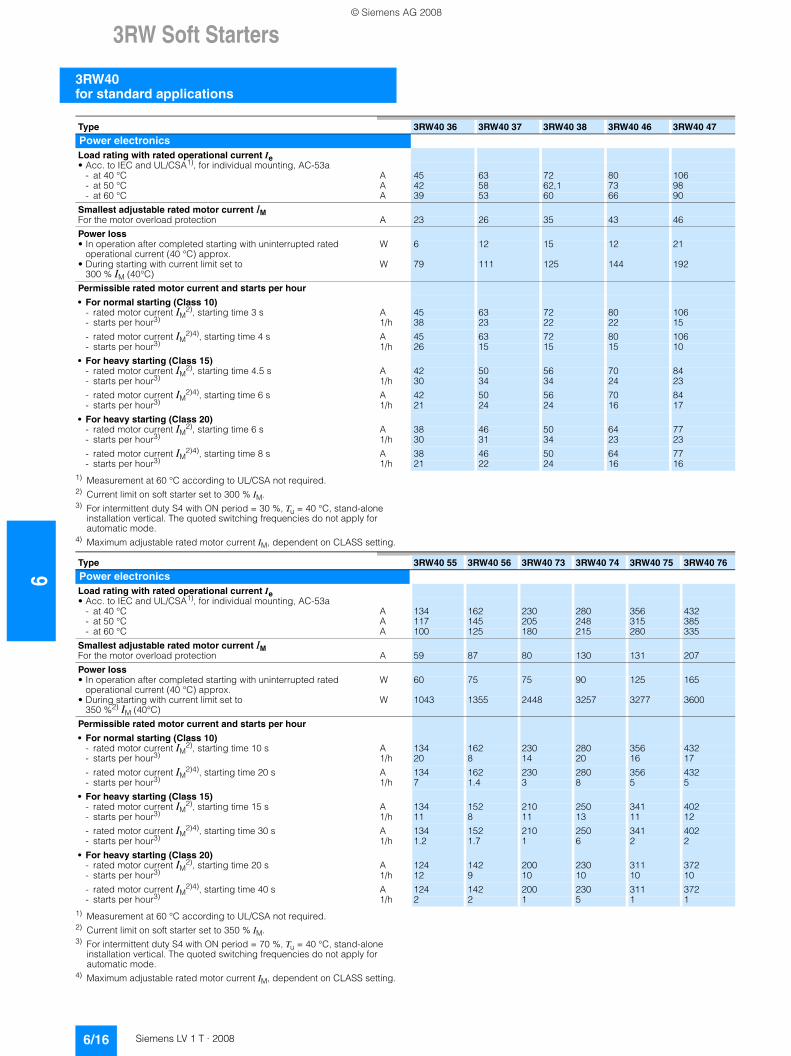
1) Measurement at 60 °C according to UL/CSA not required.2) Current limit on soft starter set to 300 % IM.3) For intermittent duty S4 with ON period = 30 %, Tu = 40 °C, stand-alone
installation vertical. The quoted switching frequencies do not apply for automatic mode.
4) Maximum adjustable rated motor current IM, dependent on CLASS setting.
1) Measurement at 60 °C according to UL/CSA not required.2) Current limit on soft starter set to 350 % IM.3) For intermittent duty S4 with ON period = 70 %, Tu = 40 °C, stand-alone
installation vertical. The quoted switching frequencies do not apply for automatic mode.
4) Maximum adjustable rated motor current IM, dependent on CLASS setting.
Type 3RW40 36 3RW40 37 3RW40 38 3RW40 46 3RW40 47
Power electronicsLoad rating with rated operational current Ie• Acc. to IEC and UL/CSA1), for individual mounting, AC-53a
- at 40 °C A 45 63 72 80 106- at 50 °C A 42 58 62,1 73 98- at 60 °C A 39 53 60 66 90
Smallest adjustable rated motor current IM For the motor overload protection A 23 26 35 43 46
Power loss• In operation after completed starting with uninterrupted rated
operational current (40 °C) approx.W 6 12 15 12 21
• During starting with current limit set to 300 % IM (40°C)
W 79 111 125 144 192
Permissible rated motor current and starts per hour
• For normal starting (Class 10)- rated motor current IM
2), starting time 3 s A 45 63 72 80 106- starts per hour3) 1/h 38 23 22 22 15
- rated motor current IM2)4), starting time 4 s A 45 63 72 80 106
- starts per hour3) 1/h 26 15 15 15 10
• For heavy starting (Class 15)- rated motor current IM
2), starting time 4.5 s A 42 50 56 70 84- starts per hour3) 1/h 30 34 34 24 23
- rated motor current IM2)4), starting time 6 s A 42 50 56 70 84
- starts per hour3) 1/h 21 24 24 16 17
• For heavy starting (Class 20)- rated motor current IM
2), starting time 6 s A 38 46 50 64 77- starts per hour3) 1/h 30 31 34 23 23
- rated motor current IM2)4), starting time 8 s A 38 46 50 64 77
- starts per hour3) 1/h 21 22 24 16 16
Type 3RW40 55 3RW40 56 3RW40 73 3RW40 74 3RW40 75 3RW40 76
Power electronicsLoad rating with rated operational current Ie• Acc. to IEC and UL/CSA1), for individual mounting, AC-53a
- at 40 °C A 134 162 230 280 356 432- at 50 °C A 117 145 205 248 315 385- at 60 °C A 100 125 180 215 280 335
Smallest adjustable rated motor current IM For the motor overload protection A 59 87 80 130 131 207
Power loss• In operation after completed starting with uninterrupted rated
operational current (40 °C) approx.W 60 75 75 90 125 165
• During starting with current limit set to 350 %2) IM (40°C)
W 1043 1355 2448 3257 3277 3600
Permissible rated motor current and starts per hour
• For normal starting (Class 10)- rated motor current IM
2), starting time 10 s A 134 162 230 280 356 432- starts per hour3) 1/h 20 8 14 20 16 17
- rated motor current IM2)4), starting time 20 s A 134 162 230 280 356 432
- starts per hour3) 1/h 7 1.4 3 8 5 5
• For heavy starting (Class 15)- rated motor current IM
2), starting time 15 s A 134 152 210 250 341 402- starts per hour3) 1/h 11 8 11 13 11 12
- rated motor current IM2)4), starting time 30 s A 134 152 210 250 341 402
- starts per hour3) 1/h 1.2 1.7 1 6 2 2
• For heavy starting (Class 20)- rated motor current IM
2), starting time 20 s A 124 142 200 230 311 372- starts per hour3) 1/h 12 9 10 10 10 10
- rated motor current IM2)4), starting time 40 s A 124 142 200 230 311 372
- starts per hour3) 1/h 2 2 1 5 1 1
© Siemens AG 2008
3RW Soft Starters
6/17Siemens LV 1 T · 2008
6
3RW40for standard applications
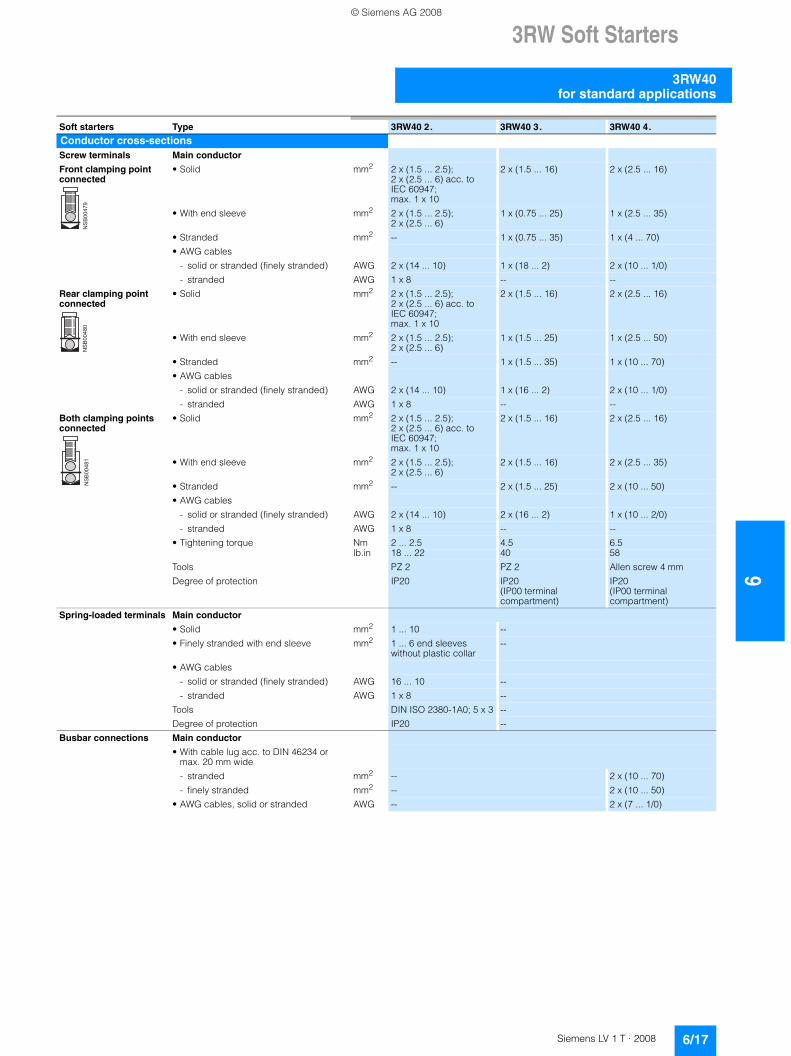
Soft starters Type 3RW40 2. 3RW40 3. 3RW40 4.
Conductor cross-sectionsScrew terminals Main conductor
Front clamping point connected
• Solid mm2 2 x (1.5 ... 2.5);2 x (2.5 ... 6) acc. to IEC 60947; max. 1 x 10
2 x (1.5 ... 16) 2 x (2.5 ... 16)
• With end sleeve mm2 2 x (1.5 ... 2.5); 2 x (2.5 ... 6)
1 x (0.75 ... 25) 1 x (2.5 ... 35)
• Stranded mm2 -- 1 x (0.75 ... 35) 1 x (4 ... 70)
• AWG cables
- solid or stranded (finely stranded) AWG 2 x (14 ... 10) 1 x (18 ... 2) 2 x (10 ... 1/0)
- stranded AWG 1 x 8 -- --
Rear clamping point connected
• Solid mm2 2 x (1.5 ... 2.5);2 x (2.5 ... 6) acc. to IEC 60947; max. 1 x 10
2 x (1.5 ... 16) 2 x (2.5 ... 16)
• With end sleeve mm2 2 x (1.5 ... 2.5); 2 x (2.5 ... 6)
1 x (1.5 ... 25) 1 x (2.5 ... 50)
• Stranded mm2 -- 1 x (1.5 ... 35) 1 x (10 ... 70)
• AWG cables
- solid or stranded (finely stranded) AWG 2 x (14 ... 10) 1 x (16 ... 2) 2 x (10 ... 1/0)
- stranded AWG 1 x 8 -- --
Both clamping points connected
• Solid mm2 2 x (1.5 ... 2.5);2 x (2.5 ... 6) acc. to IEC 60947; max. 1 x 10
2 x (1.5 ... 16) 2 x (2.5 ... 16)
• With end sleeve mm2 2 x (1.5 ... 2.5); 2 x (2.5 ... 6)
2 x (1.5 ... 16) 2 x (2.5 ... 35)
• Stranded mm2 -- 2 x (1.5 ... 25) 2 x (10 ... 50)
• AWG cables
- solid or stranded (finely stranded) AWG 2 x (14 ... 10) 2 x (16 ... 2) 1 x (10 ... 2/0)
- stranded AWG 1 x 8 -- --
• Tightening torque Nm 2 ... 2.5 4.5 6.5lb.in 18 ... 22 40 58
Tools PZ 2 PZ 2 Allen screw 4 mm
Degree of protection IP20 IP20 (IP00 terminal compartment)
IP20 (IP00 terminal compartment)
Spring-loaded terminals Main conductor
• Solid mm2 1 ... 10 --
• Finely stranded with end sleeve mm2 1 ... 6 end sleeves without plastic collar
--
• AWG cables
- solid or stranded (finely stranded) AWG 16 ... 10 --
- stranded AWG 1 x 8 --
Tools DIN ISO 2380-1A0; 5 x 3 --
Degree of protection IP20 --
Busbar connections Main conductor
• With cable lug acc. to DIN 46234 or max. 20 mm wide
- stranded mm2 -- 2 x (10 ... 70)
- finely stranded mm2 -- 2 x (10 ... 50)
• AWG cables, solid or stranded AWG -- 2 x (7 ... 1/0)
��
��
��
��
��
��
��
��
��
��
��
�
© Siemens AG 2008
63RW Soft Starters
3RW40 for standard applications
6/18 Siemens LV 1 T · 2008
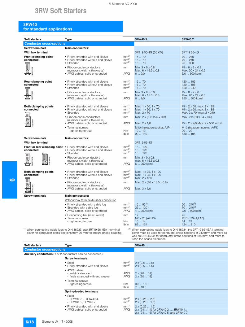
1) When connecting cable lugs to DIN 46235, use 3RT19 56-4EA1 terminal cover for conductor cross-sections from 95 mm² to ensure phase spacing.
2) When connecting cable lugs to DIN 46234, the 3RT19 66-4EA1 terminal cover must be used for conductor cross-sections of 240 mm² and more as well as DIN 46235 for conductor cross-sections of 185 mm² and more to keep the phase clearance.
Soft starters Type 3RW40 5. 3RW40 7.
Conductor cross-sectionsScrew terminals Main conductors:
With box terminal 3RT19 55-4G (55 kW) 3RT19 66-4G
Front clamping point connected
• Finely stranded with end sleeve mm2 16 ... 70 70 ... 240• Finely stranded without end sleeve mm2 16 ... 70 70 ... 240• Stranded mm2 16 ... 70 95 ... 300
• Ribbon cable conductors (number x width x thickness)
mm Min. 3 x 9 x 0.8 Max. 6 x 15.5 x 0.8
Min. 6 x 9 x 0.8Max. 20 x 24 x 0.5
• AWG cables, solid or stranded AWG 6 ... 2/0 3/0 ... 600 kcmil
Rear clamping point connected
• Finely stranded with end sleeve mm2 16 ... 70 120 ... 185• Finely stranded without end sleeve mm2 16 ... 70 120 ... 185• Stranded mm2 16 ... 70 120 ... 240
• Ribbon cable conductors (number x width x thickness)
mm Min. 3 x 9 x 0.8 Max. 6 x 15.5 x 0.8
Min. 6 x 9 x 0.8Max. 20 x 24 x 0.5
• AWG cables, solid or stranded AWG 6 ... 2/0 250 ... 500 kcmil
Both clamping points connected
• Finely stranded with end sleeve mm2 Max. 1 x 50, 1 x 70 Min. 2 x 50; max. 2 x 185• Finely stranded without end sleeve mm2 Max. 1 x 50, 1 x 70 Min. 2 x 50; max. 2 x 185• Stranded mm2 Max. 2 x 70 Max. 2 x 70; max. 2 x 240
• Ribbon cable conductors (number x width x thickness)
mm Max. 2 x (6 x 15.5 x 0.8) Max. 2 x (20 x 24 x 0.5)
• AWG cables, solid or stranded AWG Max. 2 x 1/0 Min. 2 x 2/0 Max. 2 x 500 kcmil
• Terminal screws M10 (hexagon socket, A/F4) M12 (hexagon socket, A/F5)- tightening torque Nm 10 ... 12 20 ... 22
lb.in 90 ... 110 180 ... 195
Screw terminals Main conductors:
With box terminal 3RT19 56-4G
Front or rear clamping point connected
• Finely stranded with end sleeve mm2 16 ... 120• Finely stranded without end sleeve mm2 16 ... 120• Stranded mm2 16 ... 120
• Ribbon cable conductors (number x width x thickness)
mm Min. 3 x 9 x 0.8max. 6 x 15.5 x 0.8
• AWG cables, solid or stranded AWG 6 ... 250 kcmil
Both clamping points connected
• Finely stranded with end sleeve mm2 Max. 1 x 95, 1 x 120• Finely stranded without end sleeve mm2 Max. 1 x 95, 1 x 120• Stranded mm2 Max. 2 x 120
• Ribbon cable conductors (number x width x thickness)
mm Max. 2 x (10 x 15.5 x 0.8)
• AWG cables, solid or stranded AWG Max. 2 x 3/0
Screw terminals Main conductors:
Without box terminal/busbar connection
• Finely stranded with cable lug mm2 16 ... 951) 50 ... 2402)
• Stranded with cable lug mm2 25 ... 1201) 70 ... 2402)
• AWG cables, solid or stranded AWG 4 ... 250 kcmil 2/0 ... 500 kcmil
• Connecting bar (max. width) mm 17 25• Terminal screws M8 x 25 (A/F13) M10 x 30 (A/F17)
- tightening torque Nm 10 ... 14 14 ... 24lb.in 89 ... 124 124 ... 210
��
��
��
��
��
��
��
��
��
��
��
�
��
��
��
��
��
��
��
��
��
��
��
�
Soft starters Type 3RW40 . .
Conductor cross-sectionsAuxiliary conductors (1 or 2 conductors can be connected):
Screw terminals
• Solid mm2 2 x (0.5 ... 2.5)• Finely stranded with end sleeve mm2 2 x (0.5 ... 1.5)
• AWG cables- solid or stranded AWG 2 x (20 ... 14)- finely stranded with end sleeve AWG 2 x (20 ... 16)
• Terminal screws- tightening torque Nm 0,8 ... 1.2
lb.in 7 ... 10.3
Spring-loaded terminals
• Solid- 3RW40 2. ... 3RW40 4. mm2 2 x (0.25 ... 2.5)- 3RW40 5., 3RW40 7. mm2 2 x (0.25 ... 1.5)
• Finely stranded with end sleeve mm2 2 x (0.25 ... 1.5)• AWG cables, solid or stranded AWG 2 x (24 ... 14) for 3RW40 2. ... 3RW40 4.;
2 x (24 ... 16) for 3RW40 5. and 3RW40 7.
© Siemens AG 2008
3RW Soft Starters
6/19Siemens LV 1 T · 2008
6
3RW40for standard applications
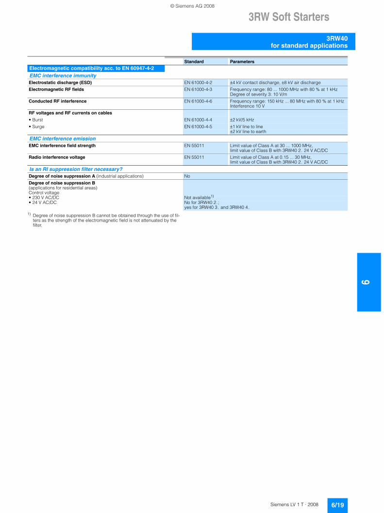
1) Degree of noise suppression B cannot be obtained through the use of fil-ters as the strength of the electromagnetic field is not attenuated by the filter.
Standard Parameters
Electromagnetic compatibility acc. to EN 60947-4-2EMC interference immunity Electrostatic discharge (ESD) EN 61000-4-2 ±4 kV contact discharge, ±8 kV air discharge
Electromagnetic RF fields EN 61000-4-3 Frequency range: 80 ... 1000 MHz with 80 % at 1 kHzDegree of severity 3: 10 V/m
Conducted RF interference EN 61000-4-6 Frequency range: 150 kHz ... 80 MHz with 80 % at 1 kHz Interference 10 V
RF voltages and RF currents on cables
• Burst EN 61000-4-4 ±2 kV/5 kHz
• Surge EN 61000-4-5 ±1 kV line to line±2 kV line to earth
EMC interference emission EMC interference field strength EN 55011 Limit value of Class A at 30 ... 1000 MHz,
limit value of Class B with 3RW40 2. 24 V AC/DC
Radio interference voltage EN 55011 Limit value of Class A at 0.15 ... 30 MHz, limit value of Class B with 3RW40 2. 24 V AC/DC
Is an RI suppression filter necessary?Degree of noise suppression A (industrial applications) No
Degree of noise suppression B (applications for residential areas) Control voltage• 230 V AC/DC Not available1)
• 24 V AC/DC No for 3RW40 2.; yes for 3RW40 3. and 3RW40 4.
© Siemens AG 2008
63RW Soft Starters
3RW40 for standard applications
6/20 Siemens LV 1 T · 2008
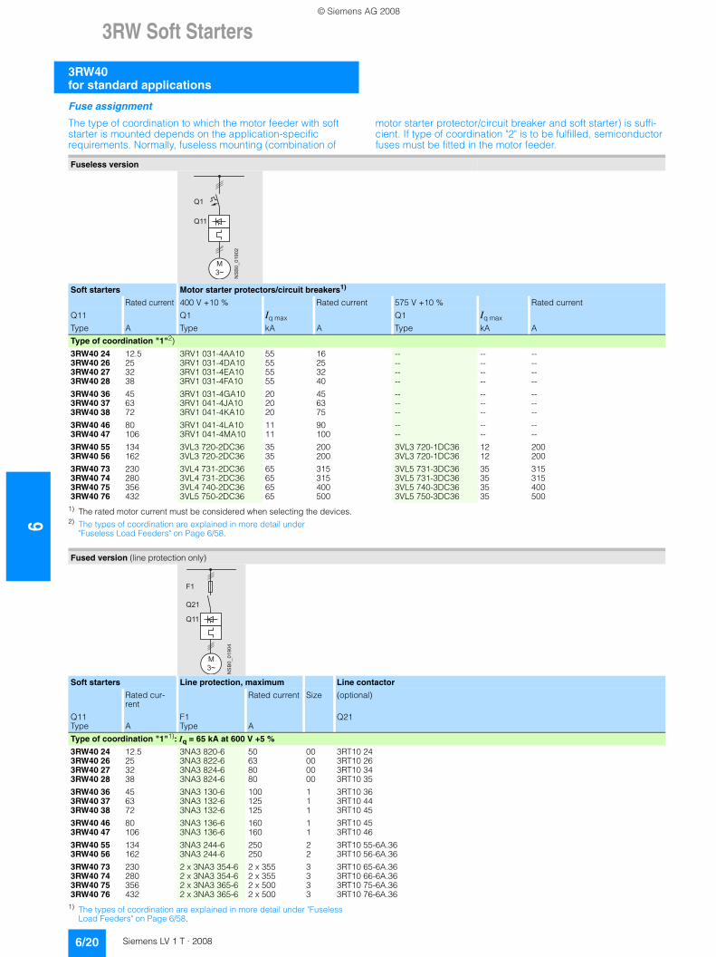
Fuse assignment
The type of coordination to which the motor feeder with soft starter is mounted depends on the application-specific requirements. Normally, fuseless mounting (combination of
motor starter protector/circuit breaker and soft starter) is suffi-cient. If type of coordination "2" is to be fulfilled, semiconductor fuses must be fitted in the motor feeder.
1) The rated motor current must be considered when selecting the devices.2) The types of coordination are explained in more detail under
"Fuseless Load Feeders" on Page 6/58.
1) The types of coordination are explained in more detail under "Fuseless Load Feeders" on Page 6/58.
Fuseless version
Soft starters Motor starter protectors/circuit breakers1)
Rated current 400 V +10 % Rated current 575 V +10 % Rated current
Q11 Q1 Iq max Q1 Iq max
Type A Type kA A Type kA A
Type of coordination "1"2)
3RW40 24 12.5 3RV1 031-4AA10 55 16 -- -- --3RW40 26 25 3RV1 031-4DA10 55 25 -- -- --3RW40 27 32 3RV1 031-4EA10 55 32 -- -- --3RW40 28 38 3RV1 031-4FA10 55 40 -- -- --
3RW40 36 45 3RV1 031-4GA10 20 45 -- -- --3RW40 37 63 3RV1 041-4JA10 20 63 -- -- --3RW40 38 72 3RV1 041-4KA10 20 75 -- -- --
3RW40 46 80 3RV1 041-4LA10 11 90 -- -- --3RW40 47 106 3RV1 041-4MA10 11 100 -- -- --
3RW40 55 134 3VL3 720-2DC36 35 200 3VL3 720-1DC36 12 2003RW40 56 162 3VL3 720-2DC36 35 200 3VL3 720-1DC36 12 200
3RW40 73 230 3VL4 731-2DC36 65 315 3VL5 731-3DC36 35 3153RW40 74 280 3VL4 731-2DC36 65 315 3VL5 731-3DC36 35 3153RW40 75 356 3VL4 740-2DC36 65 400 3VL5 740-3DC36 35 4003RW40 76 432 3VL5 750-2DC36 65 500 3VL5 750-3DC36 35 500
NS
B0_
0190
2
M3~
Q11
Q1
Fused version (line protection only)
Soft starters Line protection, maximum Line contactor
Rated cur-rent
Rated current Size (optional)
Q11 F1 Q21Type A Type A
Type of coordination "1"1): Iq = 65 kA at 600 V +5 %
3RW40 24 12.5 3NA3 820-6 50 00 3RT10 243RW40 26 25 3NA3 822-6 63 00 3RT10 263RW40 27 32 3NA3 824-6 80 00 3RT10 343RW40 28 38 3NA3 824-6 80 00 3RT10 35
3RW40 36 45 3NA3 130-6 100 1 3RT10 363RW40 37 63 3NA3 132-6 125 1 3RT10 443RW40 38 72 3NA3 132-6 125 1 3RT10 45
3RW40 46 80 3NA3 136-6 160 1 3RT10 453RW40 47 106 3NA3 136-6 160 1 3RT10 46
3RW40 55 134 3NA3 244-6 250 2 3RT10 55-6A.363RW40 56 162 3NA3 244-6 250 2 3RT10 56-6A.36
3RW40 73 230 2 x 3NA3 354-6 2 x 355 3 3RT10 65-6A.363RW40 74 280 2 x 3NA3 354-6 2 x 355 3 3RT10 66-6A.363RW40 75 356 2 x 3NA3 365-6 2 x 500 3 3RT10 75-6A.363RW40 76 432 2 x 3NA3 365-6 2 x 500 3 3RT10 76-6A.36
NS
B0_
0190
4
M3~
Q11
Q21
F1
© Siemens AG 2008
3RW Soft Starters
6/21Siemens LV 1 T · 2008
6
3RW40for standard applications
1) The types of coordination are explained in more detail under "Fuseless Load Feeders" on Page 6/58. The type of coordination "2" refers only to soft starters, not to any components in the feeder.
Fused version with 3NE1 SITOR fuses (semiconductor and line protection)
Soft starters All-range fuses Line contactor
Rated current
Rated current Size (optional)
Q11 F'1 Q21Type A Type A
Type of coordination "2"1): Iq = 65 kA at 600 V +5 %
3RW40 24 12.5 3NE1 814-0 20 000 3RT10 243RW40 26 25 3NE1 803-0 35 000 3RT10 263RW40 27 32 3NE1 020-2 80 00 3RT10 343RW40 28 38 3NE1 020-2 80 00 3RT10 35
3RW40 36 45 3NE1 020-2 80 00 3RT10 363RW40 37 63 3NE1 820-0 80 000 3RT10 443RW40 38 72 3NE1 820-0 80 000 3RT10 45
3RW40 46 80 3NE1 021-0 100 00 3RT10 453RW40 47 106 3NE1 022-0 125 00 3RT10 46
3RW40 55 134 3NE1 227-2 250 1 3RT10 55-6A.363RW40 56 162 3NE1 227-2 250 1 3RT10 56-6A.36
3RW40 73 230 3NE1 331-2 350 2 3RT10 65-6A.363RW40 74 280 3NE1 333-2 450 2 3RT10 66-6A.363RW40 75 356 3NE1 334-2 500 2 3RT10 75-6A.363RW40 76 432 3NE1 435-2 560 3 3RT10 76-6A.36
NS
B0_
0190
5
M3~
Q11
Q21
F’1
© Siemens AG 2008
63RW Soft Starters
3RW40 for standard applications
6/22 Siemens LV 1 T · 2008
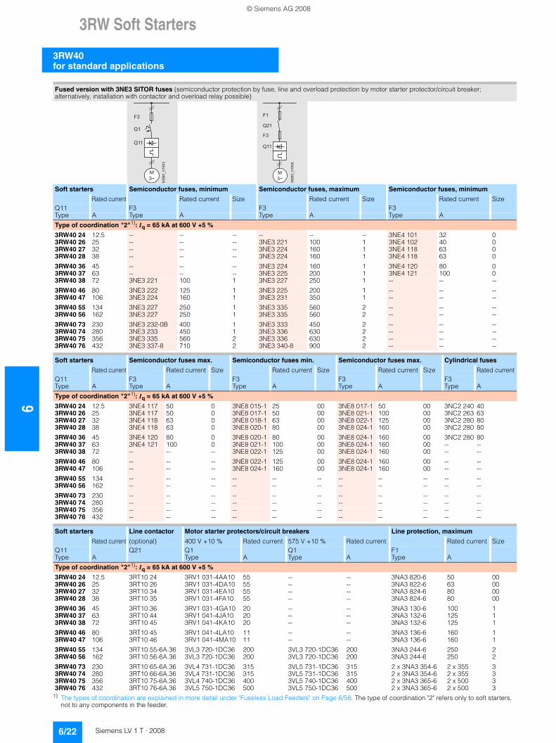
1) The types of coordination are explained in more detail under "Fuseless Load Feeders" on Page 6/58. The type of coordination "2" refers only to soft starters, not to any components in the feeder.
Fused version with 3NE3 SITOR fuses (semiconductor protection by fuse, line and overload protection by motor starter protector/circuit breaker; alternatively, installation with contactor and overload relay possible)
Soft starters Semiconductor fuses, minimum Semiconductor fuses, maximum Semiconductor fuses, minimum
Rated current Rated current Size Rated current Size Rated current SizeQ11 F3 F3 F3Type A Type A Type A Type A
Type of coordination "2"1): Iq = 65 kA at 600 V +5 %
3RW40 24 12.5 -- -- -- -- -- -- 3NE4 101 32 03RW40 26 25 -- -- -- 3NE3 221 100 1 3NE4 102 40 03RW40 27 32 -- -- -- 3NE3 224 160 1 3NE4 118 63 03RW40 28 38 -- -- -- 3NE3 224 160 1 3NE4 118 63 0
3RW40 36 45 -- -- -- 3NE3 224 160 1 3NE4 120 80 03RW40 37 63 -- -- -- 3NE3 225 200 1 3NE4 121 100 03RW40 38 72 3NE3 221 100 1 3NE3 227 250 1 -- -- --
3RW40 46 80 3NE3 222 125 1 3NE3 225 200 1 -- -- --3RW40 47 106 3NE3 224 160 1 3NE3 231 350 1 -- -- --
3RW40 55 134 3NE3 227 250 1 3NE3 335 560 2 -- -- --3RW40 56 162 3NE3 227 250 1 3NE3 335 560 2 -- -- --
3RW40 73 230 3NE3 232-0B 400 1 3NE3 333 450 2 -- -- --3RW40 74 280 3NE3 233 450 1 3NE3 336 630 2 -- -- --3RW40 75 356 3NE3 335 560 2 3NE3 336 630 2 -- -- --3RW40 76 432 3NE3 337-8 710 2 3NE3 340-8 900 2 -- -- --
Soft starters Semiconductor fuses max. Semiconductor fuses min. Semiconductor fuses max. Cylindrical fuses
Rated current Rated current Size Rated current Size Rated current Size Rated currentQ11 F3 F3 F3 F3Type A Type A Type A Type A Type A
Type of coordination "2"1): Iq = 65 kA at 600 V +5 %
3RW40 24 12.5 3NE4 117 50 0 3NE8 015-1 25 00 3NE8 017-1 50 00 3NC2 240 403RW40 26 25 3NE4 117 50 0 3NE8 017-1 50 00 3NE8 021-1 100 00 3NC2 263 633RW40 27 32 3NE4 118 63 0 3NE8 018-1 63 00 3NE8 022-1 125 00 3NC2 280 803RW40 28 38 3NE4 118 63 0 3NE8 020-1 80 00 3NE8 024-1 160 00 3NC2 280 80
3RW40 36 45 3NE4 120 80 0 3NE8 020-1 80 00 3NE8 024-1 160 00 3NC2 280 803RW40 37 63 3NE4 121 100 0 3NE8 021-1 100 00 3NE8 024-1 160 00 -- --3RW40 38 72 -- -- -- 3NE8 022-1 125 00 3NE8 024-1 160 00 -- --
3RW40 46 80 -- -- -- 3NE8 022-1 125 00 3NE8 024-1 160 00 -- --3RW40 47 106 -- -- -- 3NE8 024-1 160 00 3NE8 024-1 160 00 -- --
3RW40 55 134 -- -- -- -- -- -- -- -- -- -- --3RW40 56 162 -- -- -- -- -- -- -- -- -- -- --
3RW40 73 230 -- -- -- -- -- -- -- -- -- -- --3RW40 74 280 -- -- -- -- -- -- -- -- -- -- --3RW40 75 356 -- -- -- -- -- -- -- -- -- -- --3RW40 76 432 -- -- -- -- -- -- -- -- -- -- --
Soft starters Line contactor Motor starter protectors/circuit breakers Line protection, maximum
Rated current (optional) 400 V +10 % Rated current 575 V +10 % Rated current Rated current SizeQ11 Q21 Q1 Q1 F1Type A Type A Type A Type A
Type of coordination "2"1): Iq = 65 kA at 600 V +5 %
3RW40 24 12.5 3RT10 24 3RV1 031-4AA10 55 -- -- 3NA3 820-6 50 003RW40 26 25 3RT10 26 3RV1 031-4DA10 55 -- -- 3NA3 822-6 63 003RW40 27 32 3RT10 34 3RV1 031-4EA10 55 -- -- 3NA3 824-6 80 003RW40 28 38 3RT10 35 3RV1 031-4FA10 55 -- -- 3NA3 824-6 80 00
3RW40 36 45 3RT10 36 3RV1 031-4GA10 20 -- -- 3NA3 130-6 100 13RW40 37 63 3RT10 44 3RV1 041-4JA10 20 -- -- 3NA3 132-6 125 13RW40 38 72 3RT10 45 3RV1 041-4KA10 20 -- -- 3NA3 132-6 125 1
3RW40 46 80 3RT10 45 3RV1 041-4LA10 11 -- -- 3NA3 136-6 160 13RW40 47 106 3RT10 46 3RV1 041-4MA10 11 -- -- 3NA3 136-6 160 1
3RW40 55 134 3RT10 55-6A.36 3VL3 720-1DC36 200 3VL3 720-1DC36 200 3NA3 244-6 250 23RW40 56 162 3RT10 56-6A.36 3VL3 720-1DC36 200 3VL3 720-1DC36 200 3NA3 244-6 250 2
3RW40 73 230 3RT10 65-6A.36 3VL4 731-1DC36 315 3VL5 731-1DC36 315 2 x 3NA3 354-6 2 x 355 33RW40 74 280 3RT10 66-6A.36 3VL4 731-1DC36 315 3VL5 731-1DC36 315 2 x 3NA3 354-6 2 x 355 33RW40 75 356 3RT10 75-6A.36 3VL4 740-1DC36 400 3VL5 740-1DC36 400 2 x 3NA3 365-6 2 x 500 33RW40 76 432 3RT10 76-6A.36 3VL5 750-1DC36 500 3VL5 750-1DC36 500 2 x 3NA3 365-6 2 x 500 3
NS
B0_
0190
3
M3~
Q11
Q1
F3
NS
B0_
0190
6
M3~
Q11
Q21
F1
F3
© Siemens AG 2008
3RW Soft Starters
6/23Siemens LV 1 T · 2008
6
3RW40for standard applications
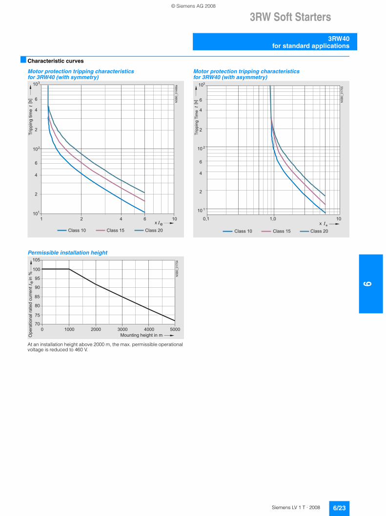
■ Characteristic curves
Motor protection tripping characteristics for 3RW40 (with symmetry)
Permissible installation height
At an installation height above 2000 m, the max. permissible operational voltage is reduced to 460 V.
Motor protection tripping characteristics for 3RW40 (with asymmetry)
101
102
103
2
4
6
2
4
6
ex2 4 6 10
NS
B0_
0148
8a
1
Class 10 Class 15 Class 20
[s]
Trip
ping
tim
e
85
105
70
75
80
90
95
100
NS
B0_
0170
4
0 1000 2000 3000 4000 5000
Ope
ratio
nal r
ated
cur
rent
I i
n %
Mounting height in m
e
10 1
10 2
103
2
4
6
2
4
6
ex1,0 10
NS
B0_
0170
5
0,1
Class 10 Class 15 Class 20
[s]
Trip
ping
Tim
e
© Siemens AG 2008
63RW Soft Starters
3RW40 for standard applications
6/24 Siemens LV 1 T · 2008
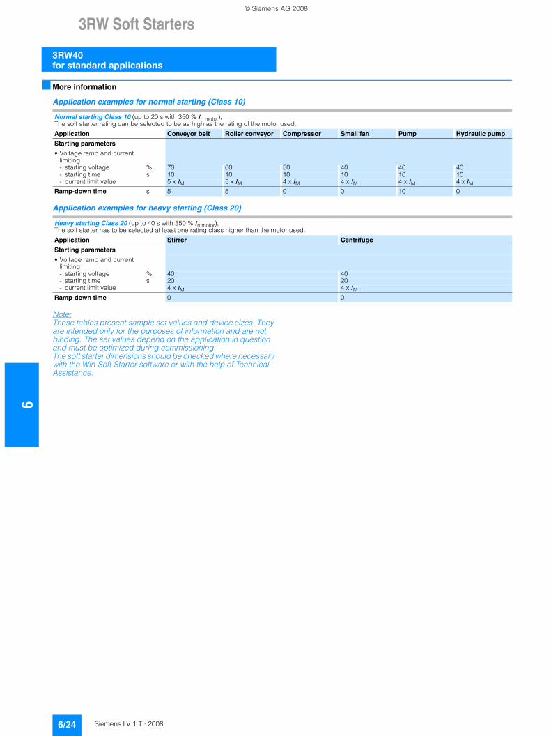
■ More information
Application examples for normal starting (Class 10)
Application examples for heavy starting (Class 20)
Note:These tables present sample set values and device sizes. They are intended only for the purposes of information and are not binding. The set values depend on the application in question and must be optimized during commissioning. The soft starter dimensions should be checked where necessary with the Win-Soft Starter software or with the help of Technical Assistance.
Normal starting Class 10 (up to 20 s with 350 % In motor), The soft starter rating can be selected to be as high as the rating of the motor used.
Application Conveyor belt Roller conveyor Compressor Small fan Pump Hydraulic pump
Starting parameters
• Voltage ramp and current limiting- starting voltage % 70 60 50 40 40 40- starting time s 10 10 10 10 10 10- current limit value 5 x IM 5 x IM 4 x IM 4 x IM 4 x IM 4 x IM
Ramp-down time s 5 5 0 0 10 0
Heavy starting Class 20 (up to 40 s with 350 % In motor), The soft starter has to be selected at least one rating class higher than the motor used.
Application Stirrer Centrifuge
Starting parameters
• Voltage ramp and current limiting- starting voltage % 40 40- starting time s 20 20- current limit value 4 x IM 4 x IM
Ramp-down time 0 0
© Siemens AG 2008
3RW Soft Starters
6/25Siemens LV 1 T · 2008
6
3RW40for standard applications
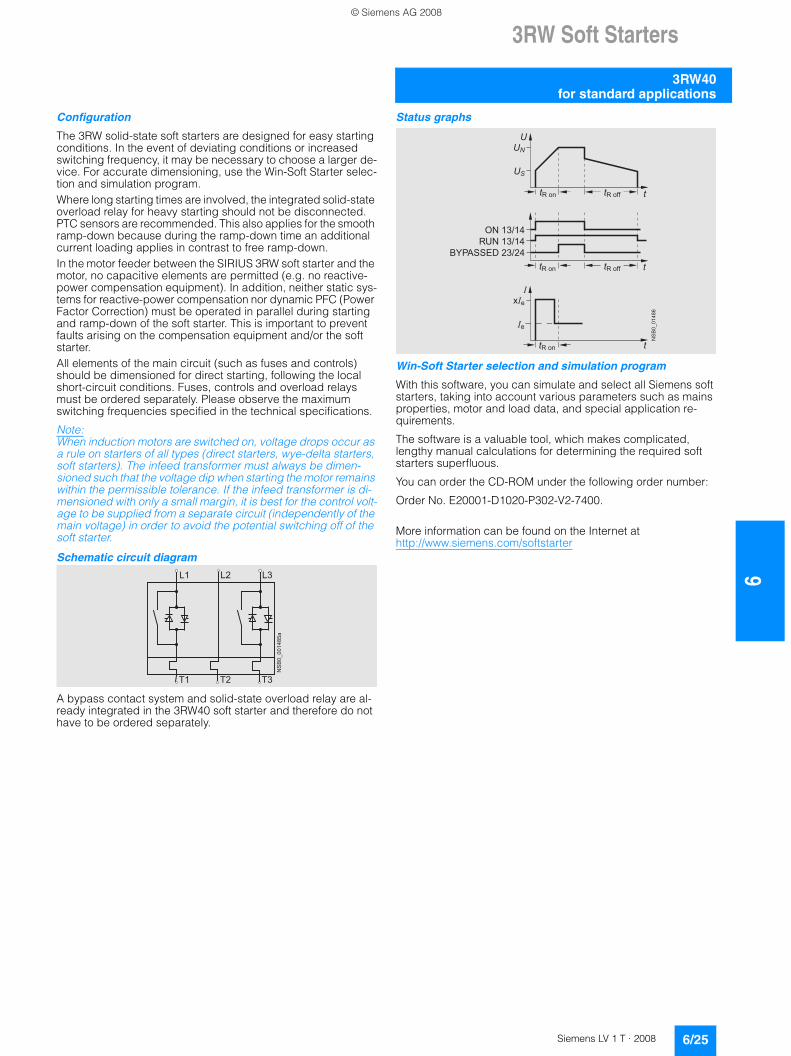
Configuration
The 3RW solid-state soft starters are designed for easy starting conditions. In the event of deviating conditions or increased switching frequency, it may be necessary to choose a larger de-vice. For accurate dimensioning, use the Win-Soft Starter selec-tion and simulation program.Where long starting times are involved, the integrated solid-state overload relay for heavy starting should not be disconnected. PTC sensors are recommended. This also applies for the smooth ramp-down because during the ramp-down time an additional current loading applies in contrast to free ramp-down. In the motor feeder between the SIRIUS 3RW soft starter and the motor, no capacitive elements are permitted (e.g. no reactive-power compensation equipment). In addition, neither static sys-tems for reactive-power compensation nor dynamic PFC (Power Factor Correction) must be operated in parallel during starting and ramp-down of the soft starter. This is important to prevent faults arising on the compensation equipment and/or the soft starter.All elements of the main circuit (such as fuses and controls) should be dimensioned for direct starting, following the local short-circuit conditions. Fuses, controls and overload relays must be ordered separately. Please observe the maximum switching frequencies specified in the technical specifications.
Note:When induction motors are switched on, voltage drops occur as a rule on starters of all types (direct starters, wye-delta starters, soft starters). The infeed transformer must always be dimen-sioned such that the voltage dip when starting the motor remains within the permissible tolerance. If the infeed transformer is di-mensioned with only a small margin, it is best for the control volt-age to be supplied from a separate circuit (independently of the main voltage) in order to avoid the potential switching off of the soft starter.
Schematic circuit diagram
A bypass contact system and solid-state overload relay are al-ready integrated in the 3RW40 soft starter and therefore do not have to be ordered separately.
Status graphs
Win-Soft Starter selection and simulation program
With this software, you can simulate and select all Siemens soft starters, taking into account various parameters such as mains properties, motor and load data, and special application re-quirements.
The software is a valuable tool, which makes complicated, lengthy manual calculations for determining the required soft starters superfluous.
You can order the CD-ROM under the following order number:
Order No. E20001-D1020-P302-V2-7400.
More information can be found on the Internet at http://www.siemens.com/softstarter
L1
NS
B0_
0014
85a
L2 L3
T1 T2 T3
����
��
����� �
���
��
����� ������
����� ������
���� �����
�������������
����
� �
�
�
�
© Siemens AG 2008
63RW Soft Starters
3RW44 for High-Feature applications
6/26 Siemens LV 1 T · 2008
■ Overview
In addition to soft starting and soft ramp-down, the solid-state SIRIUS 3RW44 soft starters provide numerous functions for higher-level requirements. They cover a performance range up to 710 kW (at 400 V) in the inline circuit and up to 1200 kW (at 400 V) in the inside-delta circuit.
The SIRIUS 3RW44 soft starters are characterized by a compact design for space-saving and clearly arranged control cabinet layouts. For optimized motor starting and stopping the innova-tive SIRIUS 3RW44 soft starters are an attractive alternative with considerable savings potential compared to applications with a frequency converter. The new torque control and adjustable cur-rent limiting enable the High-Feature soft starters to be used in nearly every conceivable task. They guarantee the reliable avoidance of sudden torque applications and current peaks dur-ing motor starting and stopping. This creates savings potential when calculating the size of the switchgear and when servicing the machinery installed. Be it for inline circuits or inside-delta cir-cuits – the SIRIUS 3RW44 soft starter offers savings especially in terms of size and equipment costs.
The bypass contacts already integrated in the soft starter by-pass the thyristors after a motor ramp-up is detected. This re-sults in a further great reduction in the heat loss occuring during operation of the soft starter at rated value.
Combinations of various starting, operating and ramp-down possibilities ensure an optimum adaptation to the application-specific requirements. Operation and commissioning can be performed with the menu-controlled keypad and a menu-prompted, multi-line graphic display with background lighting. The optimized motor ramp-up and ramp-down can be effected quickly, easily and reliably by means of just a few settings with a previously selected language. Four-key operation and plain-text displays for each menu point guarantee full clarity at every mo-ment of the parameterization and operation.
Applicable standards • IEC 60947-4-2• UL/CSA
■ Function
Equipped with modern, ergonomic user prompting the SIRIUS 3RW44 soft starters can be commissioned quickly and easily using a keypad and a menu-prompted, multi-line graphic display with background lighting. The optimized motor ramp-up and ramp-down can be effected quickly, easily and reliably by means of just a few settings with a selectable language. Four-key operation and plain-text displays for each menu point guar-antee full clarity at every moment of the parameterization and operation. During operation and when control voltage is applied, the display field continuously presents measured values and op-erating values as well as warnings and fault messages. An ex-ternal display and operator module can be connected by means of a connection cable to the soft starter, thus enabling active in-dications and the like to be read directly from the control cabinet door.
The SIRIUS 3RW44 soft starters are equipped with optimum functionality. An integral bypass contact system reduces the power loss of the soft starter during operation. This reliably prevents heating of the switchgear environment. The SIRIUS 3RW44 soft starters have internal intrinsic device protection. This prevents thermal overloading of the power sec-tion's thyristors, e.g. due to unacceptably high closing opera-tions.
Wiring outlay for installing an additional motor overload relay is no longer needed as the SIRIUS 3RW44 soft starters perform this function too. In addition they offer adjustable trip classes and a thermistor motor protection function. As an option the thy-ristors can also be protected by SITOR semiconductor fuses from short-circuiting so that the soft starter is still functional after a short-circuit (coordination type 2). And even inrush current peaks are reliably avoided thanks to adjustable current limiting.
As a further option the SIRIUS 3RW44 soft starters can be up-graded with a PROFIBUS DP module. Thanks to their communi-cation capability and their programmable control inputs and re-lay outputs the SIRIUS 3RW44 soft starters can be very easily and quickly integrated in higher-level controllers.
In addition a creep speed function is available for positioning and setting jobs. With this function the motor can be controlled in both directions of rotation with reduced torque and an adjust-able, low speed.
On the other hand the SIRIUS 3RW44 soft starters offer a new, combined DC braking function for the fast stopping of driving loads.
Highlights• Soft starting with breakaway pulse, torque control or voltage
ramp, adjustable torque or current limiting as well as any com-bination of these, depending on load type
• Integrated bypass contact system to minimize power loss• Various setting options for the starting parameters such as
starting torque, starting voltage, ramp-up and ramp-down time, and much more in three separate parameter sets
• Start-up detection• Inside-delta circuit for savings in terms of size and equipment
costs• Various ramp-down modes selectable: free ramp-down,
torque-controlled pump ramp-down, combined DC braking• Solid-state motor overload and intrinsic device protection• Thermistor motor protection• Keypad with a menu-prompted, multi-line graphic display with
background lighting• Interface for communication with the PC for more accurate set-
ting of the parameters as well as for control and monitoring• Simple adaptation to the motor feeder• Simple mounting and commissioning• Display of operating states and fault messages• Connection to PROFIBUS with optional PROFIBUS DP module• External display and operator module• Mains voltages from 200 to 690 V, 50 to 60 Hz• Applicable up to 60 °C (derating from 40 °C)
© Siemens AG 2008
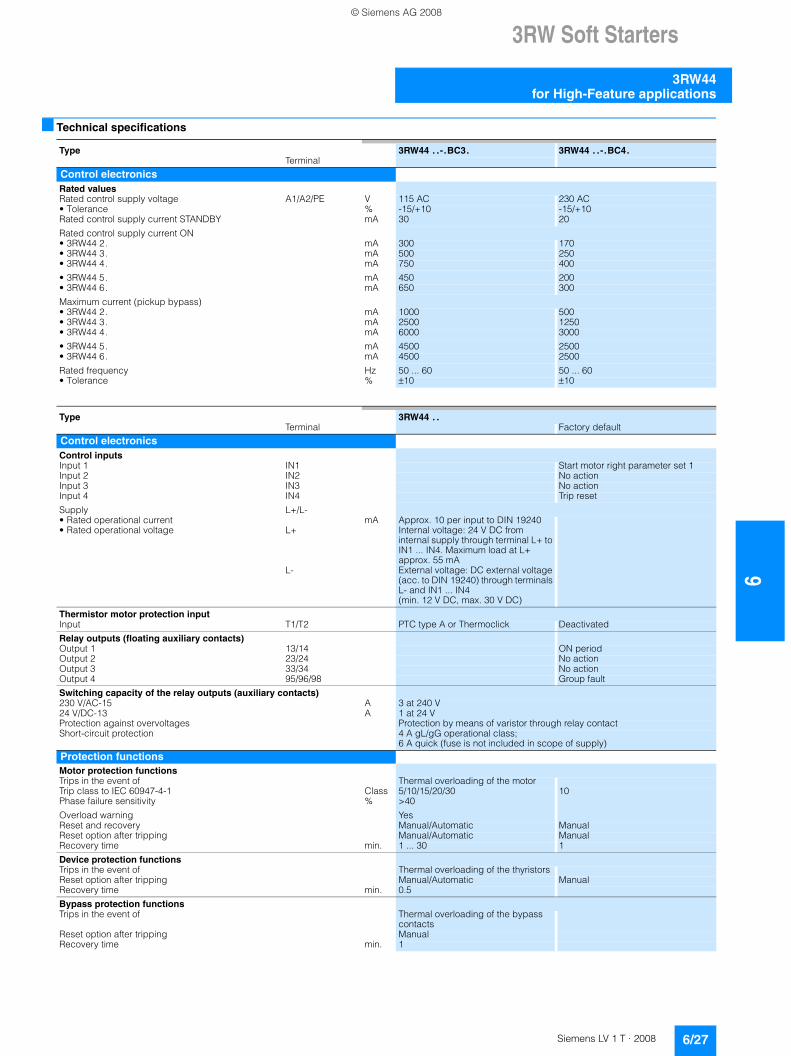
3RW Soft Starters
6/27Siemens LV 1 T · 2008
6
3RW44for High-Feature applications
■ Technical specifications
Type 3RW44 . .-.BC3. 3RW44 . .-.BC4.Terminal
Control electronicsRated valuesRated control supply voltage A1/A2/PE V 115 AC 230 AC• Tolerance % -15/+10 -15/+10Rated control supply current STANDBY mA 30 20
Rated control supply current ON• 3RW44 2. mA 300 170• 3RW44 3. mA 500 250• 3RW44 4. mA 750 400
• 3RW44 5. mA 450 200• 3RW44 6. mA 650 300
Maximum current (pickup bypass)• 3RW44 2. mA 1000 500• 3RW44 3. mA 2500 1250• 3RW44 4. mA 6000 3000
• 3RW44 5. mA 4500 2500• 3RW44 6. mA 4500 2500
Rated frequency Hz 50 ... 60 50 ... 60• Tolerance % ±10 ±10
Type 3RW44 . .Terminal Factory default
Control electronicsControl inputsInput 1 IN1 Start motor right parameter set 1Input 2 IN2 No actionInput 3 IN3 No actionInput 4 IN4 Trip reset
Supply L+/L-• Rated operational current mA Approx. 10 per input to DIN 19240• Rated operational voltage L+ Internal voltage: 24 V DC from
internal supply through terminal L+ to IN1 ... IN4. Maximum load at L+ approx. 55 mA
L- External voltage: DC external voltage (acc. to DIN 19240) through terminals L- and IN1 ... IN4(min. 12 V DC, max. 30 V DC)
Thermistor motor protection inputInput T1/T2 PTC type A or Thermoclick Deactivated
Relay outputs (floating auxiliary contacts)Output 1 13/14 ON periodOutput 2 23/24 No actionOutput 3 33/34 No actionOutput 4 95/96/98 Group fault
Switching capacity of the relay outputs (auxiliary contacts)230 V/AC-15 A 3 at 240 V24 V/DC-13 A 1 at 24 VProtection against overvoltages Protection by means of varistor through relay contactShort-circuit protection 4 A gL/gG operational class;
6 A quick (fuse is not included in scope of supply)Protection functionsMotor protection functionsTrips in the event of Thermal overloading of the motorTrip class to IEC 60947-4-1 Class 5/10/15/20/30 10Phase failure sensitivity % >40
Overload warning YesReset and recovery Manual/Automatic ManualReset option after tripping Manual/Automatic ManualRecovery time min. 1 ... 30 1
Device protection functionsTrips in the event of Thermal overloading of the thyristorsReset option after tripping Manual/Automatic ManualRecovery time min. 0.5
Bypass protection functionsTrips in the event of Thermal overloading of the bypass
contactsReset option after tripping ManualRecovery time min. 1
© Siemens AG 2008
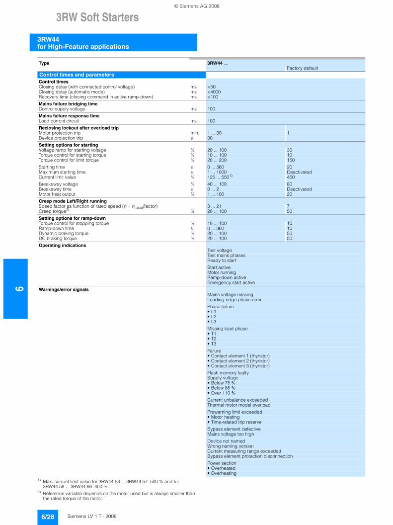
63RW Soft Starters
3RW44 for High-Feature applications
6/28 Siemens LV 1 T · 2008
1) Max. current limit value for 3RW44 53 ... 3RW44 57: 500 % and for 3RW44 58 ... 3RW44 66 :450 %.
2) Reference variable depends on the motor used but is always smaller than the rated torque of the motor.
Type 3RW44 . .Factory default
Control times and parametersControl timesClosing delay (with connected control voltage) ms <50Closing delay (automatic mode) ms <4000Recovery time (closing command in active ramp-down) ms <100
Mains failure bridging timeControl supply voltage ms 100
Mains failure response timeLoad current circuit ms 100
Reclosing lockout after overload tripMotor protection trip min. 1 ... 30 1Device protection trip s 30
Setting options for startingVoltage ramp for starting voltage % 20 ... 100 30Torque control for starting torque % 10 ... 100 10Torque control for limit torque % 20 ... 200 150
Starting time s 0 ... 360 20Maximum starting time s 1 ... 1000 DeactivatedCurrent limit value % 125 ... 5501) 450
Breakaway voltage % 40 ... 100 80Breakaway time s 0 ... 2 DeactivatedMotor heat output % 1 ... 100 20
Creep mode Left/Right runningSpeed factor as function of rated speed (n = nrated/factor) 3 ... 21 7Creep torque2) % 20 ... 100 50
Setting options for ramp-downTorque control for stopping torque % 10 ... 100 10Ramp-down time s 0 ... 360 10Dynamic braking torque % 20 ... 100 50DC braking torque % 20 ... 100 50
Operating indicationsTest voltageTest mains phasesReady to start
Start activeMotor runningRamp-down activeEmergency start active
Warnings/error signalsMains voltage missingLeading-edge phase error
Phase failure • L1• L2• L3
Missing load phase• T1• T2• T3
Failure• Contact element 1 (thyristor)• Contact element 2 (thyristor)• Contact element 3 (thyristor)
Flash memory faultySupply voltage • Below 75 %• Below 85 %• Over 110 %
Current unbalance exceededThermal motor model overload
Prewarning limit exceeded• Motor heating• Time-related trip reserve
Bypass element defectiveMains voltage too high
Device not namedWrong naming versionCurrent measuring range exceededBypass element protection disconnection
Power section• Overheated• Overheating
© Siemens AG 2008
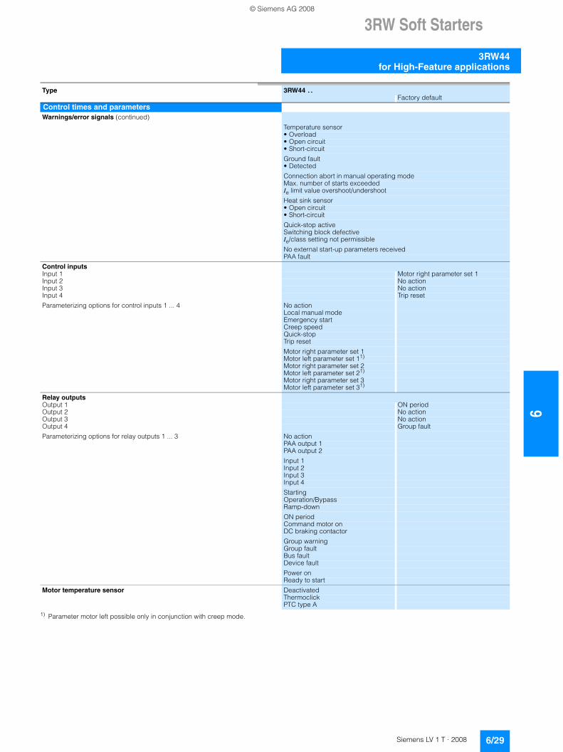
3RW Soft Starters
6/29Siemens LV 1 T · 2008
6
3RW44for High-Feature applications
1) Parameter motor left possible only in conjunction with creep mode.
Type 3RW44 . .Factory default
Control times and parametersWarnings/error signals (continued)
Temperature sensor• Overload• Open circuit• Short-circuit
Ground fault• Detected
Connection abort in manual operating modeMax. number of starts exceededIe limit value overshoot/undershoot
Heat sink sensor• Open circuit• Short-circuit
Quick-stop activeSwitching block defectiveIe/class setting not permissible
No external start-up parameters receivedPAA fault
Control inputsInput 1 Motor right parameter set 1Input 2 No actionInput 3 No actionInput 4 Trip reset
Parameterizing options for control inputs 1 ... 4 No actionLocal manual modeEmergency startCreep speedQuick-stopTrip reset
Motor right parameter set 1Motor left parameter set 11) Motor right parameter set 2Motor left parameter set 21) Motor right parameter set 3Motor left parameter set 31)
Relay outputsOutput 1 ON periodOutput 2 No actionOutput 3 No actionOutput 4 Group fault
Parameterizing options for relay outputs 1 ... 3 No actionPAA output 1PAA output 2
Input 1Input 2Input 3Input 4
StartingOperation/BypassRamp-down
ON periodCommand motor onDC braking contactor
Group warningGroup faultBus faultDevice fault
Power onReady to start
Motor temperature sensor DeactivatedThermoclickPTC type A
© Siemens AG 2008
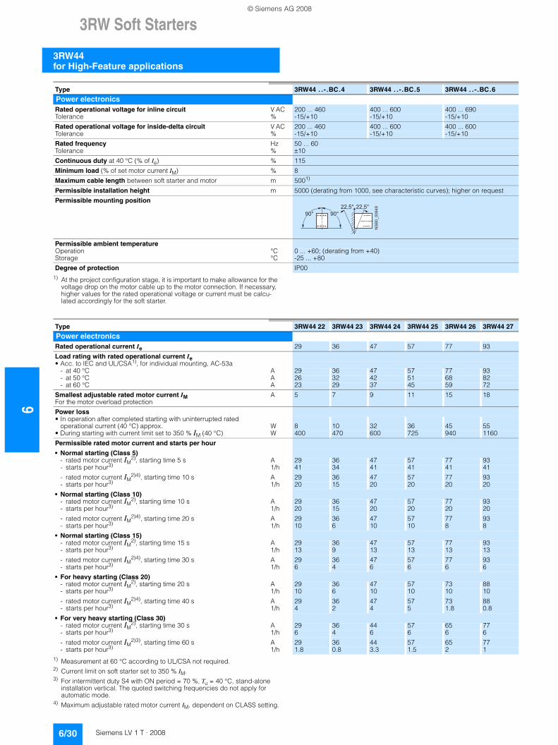
63RW Soft Starters
3RW44 for High-Feature applications
6/30 Siemens LV 1 T · 2008
1) At the project configuration stage, it is important to make allowance for the voltage drop on the motor cable up to the motor connection. If necessary, higher values for the rated operational voltage or current must be calcu-lated accordingly for the soft starter.
1) Measurement at 60 °C according to UL/CSA not required.2) Current limit on soft starter set to 350 % IM.3) For intermittent duty S4 with ON period = 70 %, Tu = 40 °C, stand-alone
installation vertical. The quoted switching frequencies do not apply for automatic mode.
4) Maximum adjustable rated motor current IM, dependent on CLASS setting.
Type 3RW44 . .-.BC.4 3RW44 . .-.BC.5 3RW44 . .-.BC.6
Power electronicsRated operational voltage for inline circuit V AC 200 ... 460 400 ... 600 400 ... 690Tolerance % -15/+10 -15/+10 -15/+10
Rated operational voltage for inside-delta circuit V AC 200 ... 460 400 ... 600 400 ... 600Tolerance % -15/+10 -15/+10 -15/+10
Rated frequency Hz 50 ... 60Tolerance % ±10
Continuous duty at 40 °C (% of Ie) % 115
Minimum load (% of set motor current IM) % 8
Maximum cable length between soft starter and motor m 5001)
Permissible installation height m 5000 (derating from 1000, see characteristic curves); higher on request
Permissible mounting position
Permissible ambient temperatureOperation °C 0 ... +60; (derating from +40)Storage °C -25 ... +80
Degree of protection IP00
���������� � � � �
� � �� � �
Type 3RW44 22 3RW44 23 3RW44 24 3RW44 25 3RW44 26 3RW44 27
Power electronicsRated operational current Ie 29 36 47 57 77 93
Load rating with rated operational current Ie• Acc. to IEC and UL/CSA1), for individual mounting, AC-53a
- at 40 °C A 29 36 47 57 77 93- at 50 °C A 26 32 42 51 68 82- at 60 °C A 23 29 37 45 59 72
Smallest adjustable rated motor current IM For the motor overload protection
A 5 7 9 11 15 18
Power loss• In operation after completed starting with uninterrupted rated
operational current (40 °C) approx. W 8 10 32 36 45 55• During starting with current limit set to 350 % IM (40 °C) W 400 470 600 725 940 1160
Permissible rated motor current and starts per hour
• Normal starting (Class 5)- rated motor current IM
2), starting time 5 s A 29 36 47 57 77 93- starts per hour3) 1/h 41 34 41 41 41 41
- rated motor current IM2)4), starting time 10 s A 29 36 47 57 77 93
- starts per hour3) 1/h 20 15 20 20 20 20
• Normal starting (Class 10)- rated motor current IM
2), starting time 10 s A 29 36 47 57 77 93- starts per hour3) 1/h 20 15 20 20 20 20
- rated motor current IM2)4), starting time 20 s A 29 36 47 57 77 93
- starts per hour3) 1/h 10 6 10 10 8 8
• Normal starting (Class 15)- rated motor current IM
2), starting time 15 s A 29 36 47 57 77 93- starts per hour3) 1/h 13 9 13 13 13 13
- rated motor current IM2)4), starting time 30 s A 29 36 47 57 77 93
- starts per hour3) 1/h 6 4 6 6 6 6
• For heavy starting (Class 20)- rated motor current IM
2), starting time 20 s A 29 36 47 57 73 88- starts per hour3) 1/h 10 6 10 10 10 10
- rated motor current IM2)4), starting time 40 s A 29 36 47 57 73 88
- starts per hour3) 1/h 4 2 4 5 1.8 0.8
• For very heavy starting (Class 30)- rated motor current IM
2), starting time 30 s A 29 36 44 57 65 77- starts per hour3) 1/h 6 4 6 6 6 6
- rated motor current IM2)3), starting time 60 s A 29 36 44 57 65 77
- starts per hour3) 1/h 1.8 0.8 3.3 1.5 2 1
© Siemens AG 2008
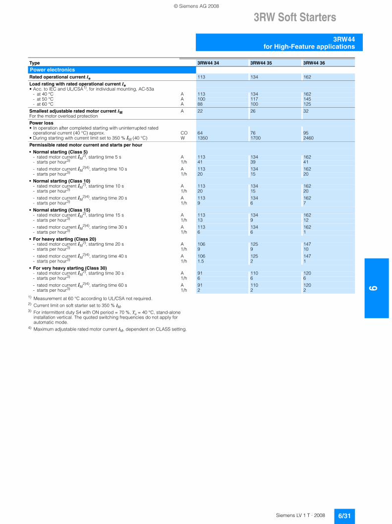
3RW Soft Starters
6/31Siemens LV 1 T · 2008
6
3RW44for High-Feature applications
1) Measurement at 60 °C according to UL/CSA not required.2) Current limit on soft starter set to 350 % IM.3) For intermittent duty S4 with ON period = 70 %, Tu = 40 °C, stand-alone
installation vertical. The quoted switching frequencies do not apply for automatic mode.
4) Maximum adjustable rated motor current IM, dependent on CLASS setting.
Type 3RW44 34 3RW44 35 3RW44 36
Power electronicsRated operational current Ie 113 134 162
Load rating with rated operational current Ie• Acc. to IEC and UL/CSA1), for individual mounting, AC-53a
- at 40 °C A 113 134 162- at 50 °C A 100 117 145- at 60 °C A 88 100 125
Smallest adjustable rated motor current IM For the motor overload protection
A 22 26 32
Power loss• In operation after completed starting with uninterrupted rated
operational current (40 °C) approx. CO 64 76 95• During starting with current limit set to 350 % IM (40 °C) W 1350 1700 2460
Permissible rated motor current and starts per hour
• Normal starting (Class 5)- rated motor current IM
2), starting time 5 s A 113 134 162- starts per hour3) 1/h 41 39 41
- rated motor current IM2)4), starting time 10 s A 113 134 162
- starts per hour3) 1/h 20 15 20
• Normal starting (Class 10)- rated motor current IM
2), starting time 10 s A 113 134 162- starts per hour3) 1/h 20 15 20
- rated motor current IM2)4), starting time 20 s A 113 134 162
- starts per hour3) 1/h 9 6 7
• Normal starting (Class 15)- rated motor current IM
2), starting time 15 s A 113 134 162- starts per hour3) 1/h 13 9 12
- rated motor current IM2)4), starting time 30 s A 113 134 162
- starts per hour3) 1/h 6 6 1
• For heavy starting (Class 20)- rated motor current IM
2), starting time 20 s A 106 125 147- starts per hour3) 1/h 9 9 10
- rated motor current IM2)4), starting time 40 s A 106 125 147
- starts per hour3) 1/h 1.5 2 1
• For very heavy starting (Class 30)- rated motor current IM
2), starting time 30 s A 91 110 120- starts per hour3) 1/h 6 6 6
- rated motor current IM2)4), starting time 60 s A 91 110 120
- starts per hour3) 1/h 2 2 2
© Siemens AG 2008
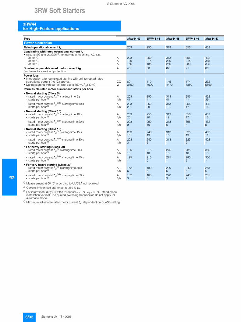
63RW Soft Starters
3RW44 for High-Feature applications
6/32 Siemens LV 1 T · 2008
1) Measurement at 60 °C according to UL/CSA not required.2) Current limit on soft starter set to 350 % IM.3) For intermittent duty S4 with ON period = 70 %, Tu = 40 °C, stand-alone
installation vertical. The quoted switching frequencies do not apply for automatic mode.
4) Maximum adjustable rated motor current IM, dependent on CLASS setting.
Type 3RW44 43 3RW44 44 3RW44 45 3RW44 46 3RW44 47
Power electronicsRated operational current Ie 203 250 313 356 432
Load rating with rated operational current Ie• Acc. to IEC and UL/CSA1), for individual mounting, AC-53a
- at 40 °C A 203 250 313 356 432- at 50 °C A 180 215 280 315 385- at 60 °C A 156 185 250 280 335
Smallest adjustable rated motor current IM For the motor overload protection
A 40 50 62 71 86
Power loss• In operation after completed starting with uninterrupted rated
operational current (40 °C) approx. CO 89 110 145 174 232• During starting with current limit set to 350 % IM (40 °C) W 3350 4000 4470 5350 5860
Permissible rated motor current and starts per hour
• Normal starting (Class 5)- rated motor current IM
2), starting time 5 s A 203 250 313 356 432- starts per hour3) 1/h 41 41 41 41 39
- rated motor current IM2)4), starting time 10 s A 203 250 313 356 432
- starts per hour3) 1/h 20 20 19 17 16
• Normal starting (Class 10)- rated motor current IM
2), starting time 10 s A 203 250 313 356 432- starts per hour3) 1/h 20 20 19 17 16
- rated motor current IM2)4), starting time 20 s A 203 250 313 356 432
- starts per hour3) 1/h 9 10 6 4 5
• Normal starting (Class 15)- rated motor current IM
2), starting time 15 s A 203 240 313 325 402- starts per hour3) 1/h 13 13 10 13 11
- rated motor current IM2)4), starting time 30 s A 203 240 313 325 402
- starts per hour3) 1/h 3 6 1 2 1
• For heavy starting (Class 20)- rated motor current IM
2), starting time 20 s A 195 215 275 285 356- starts per hour3) 1/h 10 10 10 10 10
- rated motor current IM2)4), starting time 40 s A 195 215 275 285 356
- starts per hour3) 1/h 1 5 1 3 1
• For very heavy starting (Class 30)- rated motor current IM
2), starting time 30 s A 162 180 220 240 285- starts per hour3) 1/h 6 6 6 6 6
- rated motor current IM2)4), starting time 60 s A 162 180 220 240 285
- starts per hour3) 1/h 3 3 3 2 1
© Siemens AG 2008

3RW Soft Starters
6/33Siemens LV 1 T · 2008
6
3RW44for High-Feature applications
1) Measurement at 60 °C according to UL/CSA not required.2) Current limit on soft starter set to 350 % IM.3) For intermittent duty S4 with ON period = 70 %, Tu = 40 °C, stand-alone
installation vertical. The quoted switching frequencies do not apply for automatic mode.
4) Maximum adjustable rated motor current IM, dependent on CLASS setting.
Type 3RW44 53 3RW44 54 3RW44 55 3RW44 56 3RW44 57 3RW44 58
Power electronicsRated operational current Ie 551 615 693 780 880 970
Load rating with rated operational current Ie• Acc. to IEC and UL/CSA1), for individual mounting, AC-53a
- at 40 °C A 551 615 693 780 880 970- at 50 °C A 494 551 615 693 780 850- at 60 °C A 438 489 551 615 693 760
Smallest adjustable rated motor current IM For the motor overload protection
A 110 123 138 156 176 194
Power loss• In operation after completed starting with uninterrupted rated
operational current (40 °C) approx. CO 159 186 220 214 250 270• During starting with current limit set to 350 % IM (40 °C) W 7020 8100 9500 11100 13100 15000
Permissible rated motor current and starts per hour
• Normal starting (Class 5)- rated motor current IM
2), starting time 5 s A 551 615 693 780 880 970- starts per hour3) 1/h 41 41 37 33 22 17
- rated motor current IM2)4), starting time 10 s A 551 615 693 780 880 970
- starts per hour3) 1/h 20 20 16 13 8 5
• Normal starting (Class 10)- rated motor current IM
2), starting time 10 s A 551 615 693 780 880 970- starts per hour3) 1/h 20 20 16 13 8 5
- rated motor current IM2)4), starting time 20 s A 551 615 693 780 880 970
- starts per hour3) 1/h 10 9 6 4 0.3 0.3
• Normal starting (Class 15)- rated motor current IM
2), starting time 15 s A 551 615 666 723 780 821- starts per hour3) 1/h 13 13 11 9 8 8
- rated motor current IM2)4), starting time 30 s A 551 615 666 723 780 821
- starts per hour3) 1/h 6 4 3 1 0,4 0.5
• For heavy starting (Class 20)- rated motor current IM
2), starting time 20 s A 551 591 633 670 710 740- starts per hour3) 1/h 10 10 7 8 8 9
- rated motor current IM2)4), starting time 40 s A 551 591 633 670 710 740
- starts per hour3) 1/h 4 2 1 1 0,4 1
• For very heavy starting (Class 30)- rated motor current IM
2), starting time 30 s A 500 525 551 575 600 630- starts per hour3) 1/h 6 6 6 6 6 6
- rated motor current IM2)4), starting time 60 s A 500 525 551 575 600 630
- starts per hour3) 1/h 2 1 1 1 1.5 1
© Siemens AG 2008
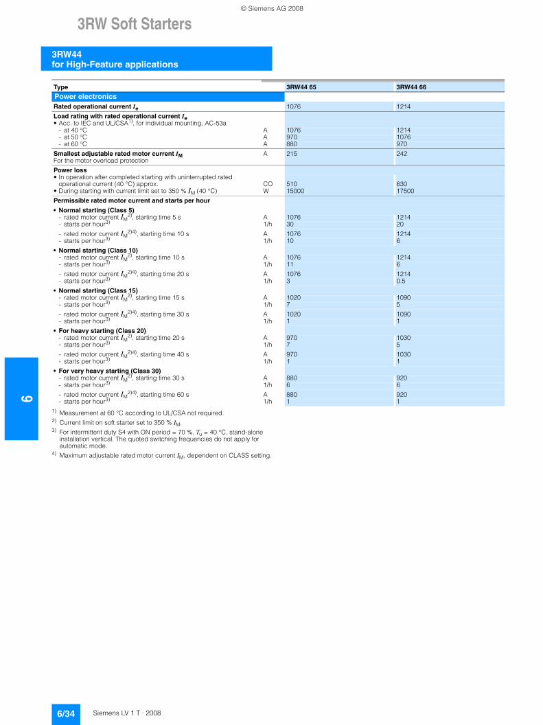
63RW Soft Starters
3RW44 for High-Feature applications
6/34 Siemens LV 1 T · 2008
1) Measurement at 60 °C according to UL/CSA not required.2) Current limit on soft starter set to 350 % IM.3) For intermittent duty S4 with ON period = 70 %, Tu = 40 °C, stand-alone
installation vertical. The quoted switching frequencies do not apply for automatic mode.
4) Maximum adjustable rated motor current IM, dependent on CLASS setting.
Type 3RW44 65 3RW44 66
Power electronicsRated operational current Ie 1076 1214
Load rating with rated operational current Ie• Acc. to IEC and UL/CSA1), for individual mounting, AC-53a
- at 40 °C A 1076 1214- at 50 °C A 970 1076- at 60 °C A 880 970
Smallest adjustable rated motor current IMFor the motor overload protection
A 215 242
Power loss• In operation after completed starting with uninterrupted rated
operational current (40 °C) approx. CO 510 630• During starting with current limit set to 350 % IM (40 °C) W 15000 17500
Permissible rated motor current and starts per hour
• Normal starting (Class 5)- rated motor current IM
2), starting time 5 s A 1076 1214- starts per hour3) 1/h 30 20
- rated motor current IM2)4), starting time 10 s A 1076 1214
- starts per hour3) 1/h 10 6
• Normal starting (Class 10)- rated motor current IM
2), starting time 10 s A 1076 1214- starts per hour3) 1/h 11 6
- rated motor current IM2)4), starting time 20 s A 1076 1214
- starts per hour3) 1/h 3 0.5
• Normal starting (Class 15)- rated motor current IM
2), starting time 15 s A 1020 1090- starts per hour3) 1/h 7 5
- rated motor current IM2)4), starting time 30 s A 1020 1090
- starts per hour3) 1/h 1 1
• For heavy starting (Class 20)- rated motor current IM
2), starting time 20 s A 970 1030- starts per hour3) 1/h 7 5
- rated motor current IM2)4), starting time 40 s A 970 1030
- starts per hour3) 1/h 1 1
• For very heavy starting (Class 30)- rated motor current IM
2), starting time 30 s A 880 920- starts per hour3) 1/h 6 6
- rated motor current IM2)4), starting time 60 s A 880 920
- starts per hour3) 1/h 1 1
© Siemens AG 2008
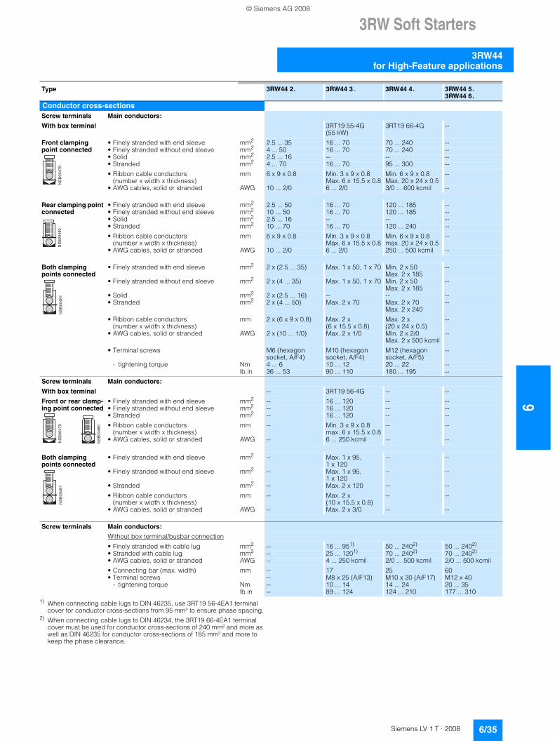
3RW Soft Starters
6/35Siemens LV 1 T · 2008
6
3RW44for High-Feature applications
1) When connecting cable lugs to DIN 46235, use 3RT19 56-4EA1 terminal cover for conductor cross-sections from 95 mm² to ensure phase spacing.
2) When connecting cable lugs to DIN 46234, the 3RT19 66-4EA1 terminal cover must be used for conductor cross-sections of 240 mm² and more as well as DIN 46235 for conductor cross-sections of 185 mm² and more to keep the phase clearance.
Type 3RW44 2. 3RW44 3. 3RW44 4. 3RW44 5. 3RW44 6.
Conductor cross-sectionsScrew terminals Main conductors:
With box terminal 3RT19 55-4G (55 kW)
3RT19 66-4G --
Front clamping point connected
• Finely stranded with end sleeve mm2 2.5 ... 35 16 ... 70 70 ... 240 --• Finely stranded without end sleeve mm2 4 ... 50 16 ... 70 70 ... 240 --• Solid mm2 2.5 ... 16 -- -- --• Stranded mm2 4 ... 70 16 ... 70 95 ... 300 --
• Ribbon cable conductors (number x width x thickness)
mm 6 x 9 x 0.8 Min. 3 x 9 x 0.8 Max. 6 x 15.5 x 0.8
Min. 6 x 9 x 0.8Max. 20 x 24 x 0.5
--
• AWG cables, solid or stranded AWG 10 ... 2/0 6 ... 2/0 3/0 ... 600 kcmil --
Rear clamping point connected
• Finely stranded with end sleeve mm2 2.5 ... 50 16 ... 70 120 ... 185 --• Finely stranded without end sleeve mm2 10 ... 50 16 ... 70 120 ... 185 --• Solid mm2 2.5 ... 16 -- -- --• Stranded mm2 10 ... 70 16 ... 70 120 ... 240 --
• Ribbon cable conductors (number x width x thickness)
mm 6 x 9 x 0.8 Min. 3 x 9 x 0.8 Max. 6 x 15.5 x 0.8
Min. 6 x 9 x 0.8max. 20 x 24 x 0.5
--
• AWG cables, solid or stranded AWG 10 ... 2/0 6 ... 2/0 250 ... 500 kcmil --
Both clamping points connected
• Finely stranded with end sleeve mm2 2 x (2.5 ... 35) Max. 1 x 50, 1 x 70 Min. 2 x 50 Max. 2 x 185
--
• Finely stranded without end sleeve mm2 2 x (4 ... 35) Max. 1 x 50, 1 x 70 Min. 2 x 50 Max. 2 x 185
--
• Solid mm2 2 x (2.5 ... 16) -- -- --• Stranded mm2 2 x (4 ... 50) Max. 2 x 70 Max. 2 x 70
Max. 2 x 240--
• Ribbon cable conductors (number x width x thickness)
mm 2 x (6 x 9 x 0.8) Max. 2 x(6 x 15.5 x 0.8)
Max. 2 x(20 x 24 x 0.5)
--
• AWG cables, solid or stranded AWG 2 x (10 ... 1/0) Max. 2 x 1/0 Min. 2 x 2/0 Max. 2 x 500 kcmil
--
• Terminal screws M6 (hexagon socket, A/F4)
M10 (hexagon socket, A/F4)
M12 (hexagon socket, A/F5)
--
- tightening torque Nm 4 ... 6 10 ... 12 20 ... 22 --lb.in 36 ... 53 90 ... 110 180 ... 195 --
Screw terminals Main conductors:
With box terminal -- 3RT19 56-4G -- --
Front or rear clamp-ing point connected
• Finely stranded with end sleeve mm2 -- 16 ... 120 -- --• Finely stranded without end sleeve mm2 -- 16 ... 120 -- --• Stranded mm2 -- 16 ... 120 -- --
• Ribbon cable conductors (number x width x thickness)
mm -- Min. 3 x 9 x 0.8max. 6 x 15.5 x 0.8
-- --
• AWG cables, solid or stranded AWG -- 6 ... 250 kcmil -- --
Both clamping points connected
• Finely stranded with end sleeve mm2 -- Max. 1 x 95, 1 x 120
-- --
• Finely stranded without end sleeve mm2 -- Max. 1 x 95, 1 x 120
-- --
• Stranded mm2 -- Max. 2 x 120 -- --
• Ribbon cable conductors (number x width x thickness)
mm -- Max. 2 x(10 x 15.5 x 0.8)
-- --
• AWG cables, solid or stranded AWG -- Max. 2 x 3/0 -- --
Screw terminals Main conductors:
Without box terminal/busbar connection
• Finely stranded with cable lug mm2 -- 16 ... 951) 50 ... 2402) 50 ... 2402)
• Stranded with cable lug mm2 -- 25 ... 1201) 70 ... 2402) 70 ... 2402)
• AWG cables, solid or stranded AWG -- 4 ... 250 kcmil 2/0 ... 500 kcmil 2/0 ... 500 kcmil
• Connecting bar (max. width) mm -- 17 25 60• Terminal screws -- M8 x 25 (A/F13) M10 x 30 (A/F17) M12 x 40
- tightening torque Nm -- 10 ... 14 14 ... 24 20 ... 35lb.in -- 89 ... 124 124 ... 210 177 ... 310
��
��
��
��
��
��
��
��
��
��
��
�
��
��
��
��
��
��
��
��
��
��
��
�
© Siemens AG 2008
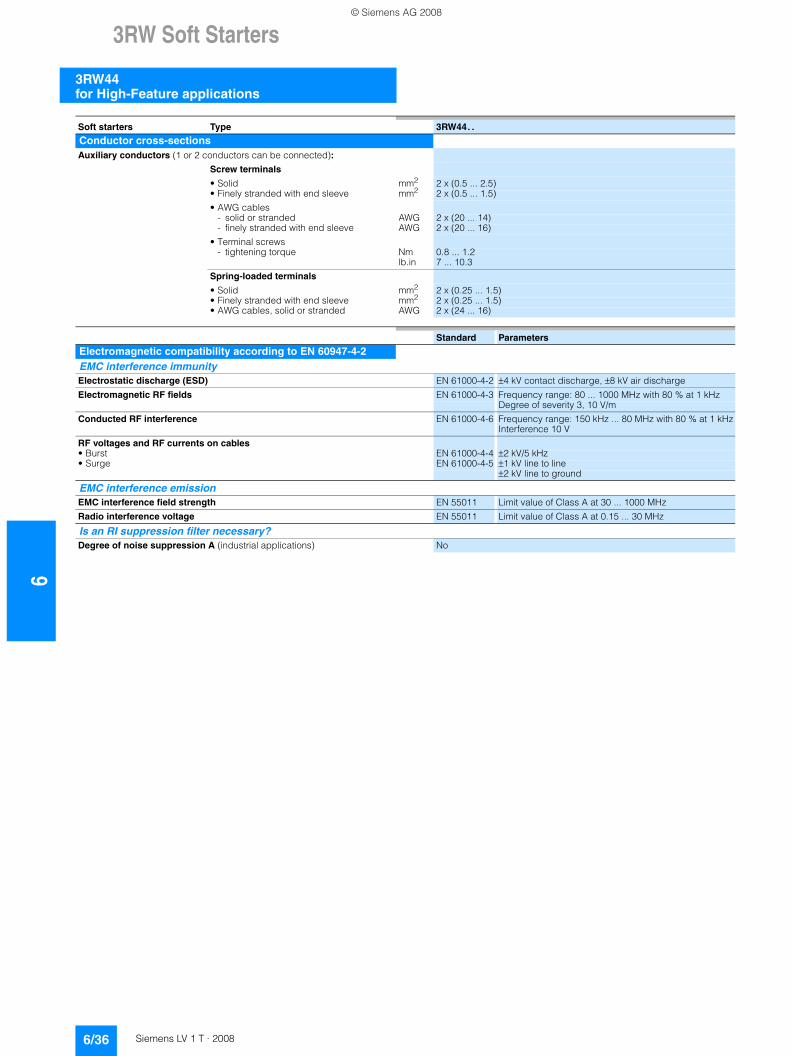
63RW Soft Starters
3RW44 for High-Feature applications
6/36 Siemens LV 1 T · 2008
Soft starters Type 3RW44. .
Conductor cross-sectionsAuxiliary conductors (1 or 2 conductors can be connected):
Screw terminals
• Solid mm2 2 x (0.5 ... 2.5)• Finely stranded with end sleeve mm2 2 x (0.5 ... 1.5)
• AWG cables- solid or stranded AWG 2 x (20 ... 14)- finely stranded with end sleeve AWG 2 x (20 ... 16)
• Terminal screws- tightening torque Nm 0.8 ... 1.2
lb.in 7 ... 10.3
Spring-loaded terminals
• Solid mm2 2 x (0.25 ... 1.5)• Finely stranded with end sleeve mm2 2 x (0.25 ... 1.5)• AWG cables, solid or stranded AWG 2 x (24 ... 16)
Standard Parameters
Electromagnetic compatibility according to EN 60947-4-2EMC interference immunity Electrostatic discharge (ESD) EN 61000-4-2 ±4 kV contact discharge, ±8 kV air discharge
Electromagnetic RF fields EN 61000-4-3 Frequency range: 80 ... 1000 MHz with 80 % at 1 kHzDegree of severity 3, 10 V/m
Conducted RF interference EN 61000-4-6 Frequency range: 150 kHz ... 80 MHz with 80 % at 1 kHzInterference 10 V
RF voltages and RF currents on cables• Burst EN 61000-4-4 ±2 kV/5 kHz• Surge EN 61000-4-5 ±1 kV line to line
±2 kV line to ground
EMC interference emission EMC interference field strength EN 55011 Limit value of Class A at 30 ... 1000 MHz
Radio interference voltage EN 55011 Limit value of Class A at 0.15 ... 30 MHz
Is an RI suppression filter necessary?Degree of noise suppression A (industrial applications) No
© Siemens AG 2008
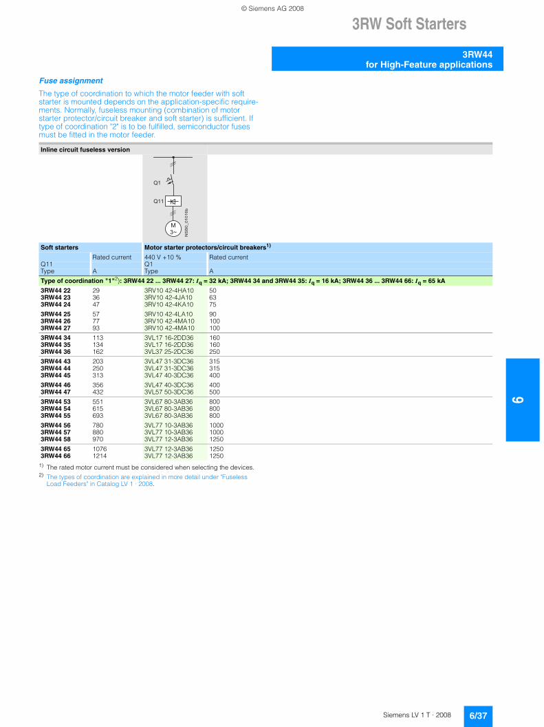
3RW Soft Starters
6/37Siemens LV 1 T · 2008
6
3RW44for High-Feature applications
Fuse assignment
The type of coordination to which the motor feeder with soft starter is mounted depends on the application-specific require-ments. Normally, fuseless mounting (combination of motor starter protector/circuit breaker and soft starter) is sufficient. If type of coordination "2" is to be fulfilled, semiconductor fuses must be fitted in the motor feeder.
1) The rated motor current must be considered when selecting the devices.2) The types of coordination are explained in more detail under "Fuseless
Load Feeders" in Catalog LV 1 · 2008.
Inline circuit fuseless version
Soft starters Motor starter protectors/circuit breakers1)
Rated current 440 V +10 % Rated currentQ11 Q1Type A Type A
Type of coordination "1"2): 3RW44 22 ... 3RW44 27: Iq = 32 kA; 3RW44 34 and 3RW44 35: Iq = 16 kA; 3RW44 36 ... 3RW44 66: Iq = 65 kA
3RW44 22 29 3RV10 42-4HA10 503RW44 23 36 3RV10 42-4JA10 633RW44 24 47 3RV10 42-4KA10 75
3RW44 25 57 3RV10 42-4LA10 903RW44 26 77 3RV10 42-4MA10 1003RW44 27 93 3RV10 42-4MA10 100
3RW44 34 113 3VL17 16-2DD36 1603RW44 35 134 3VL17 16-2DD36 1603RW44 36 162 3VL37 25-2DC36 250
3RW44 43 203 3VL47 31-3DC36 3153RW44 44 250 3VL47 31-3DC36 3153RW44 45 313 3VL47 40-3DC36 400
3RW44 46 356 3VL47 40-3DC36 4003RW44 47 432 3VL57 50-3DC36 500
3RW44 53 551 3VL67 80-3AB36 8003RW44 54 615 3VL67 80-3AB36 8003RW44 55 693 3VL67 80-3AB36 800
3RW44 56 780 3VL77 10-3AB36 10003RW44 57 880 3VL77 10-3AB36 10003RW44 58 970 3VL77 12-3AB36 1250
3RW44 65 1076 3VL77 12-3AB36 12503RW44 66 1214 3VL77 12-3AB36 1250
� � �
����������
� �
� �
© Siemens AG 2008
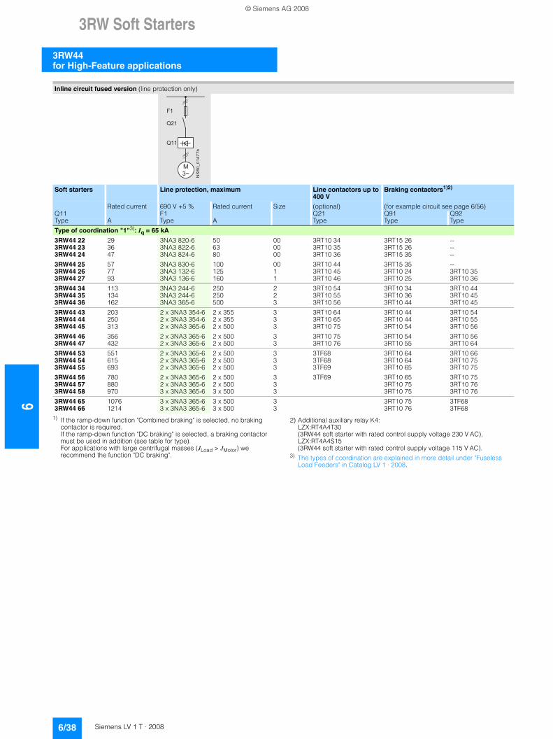
63RW Soft Starters
3RW44 for High-Feature applications
6/38 Siemens LV 1 T · 2008
1) If the ramp-down function "Combined braking" is selected, no braking contactor is required. If the ramp-down function "DC braking" is selected, a braking contactor must be used in addition (see table for type). For applications with large centrifugal masses (JLoad > JMotor) we recommend the function "DC braking".
2) Additional auxiliary relay K4: LZX:RT4A4T30 (3RW44 soft starter with rated control supply voltage 230 V AC), LZX:RT4A4S15 (3RW44 soft starter with rated control supply voltage 115 V AC).
3) The types of coordination are explained in more detail under "Fuseless Load Feeders" in Catalog LV 1 · 2008.
Inline circuit fused version (line protection only)
Soft starters Line protection, maximum Line contactors up to 400 V
Braking contactors1)2)
Rated current 690 V +5 % Rated current Size (optional) (for example circuit see page 6/56)Q11 F1 Q21 Q91 Q92Type A Type A Type Type Type
Type of coordination "1"3): Iq = 65 kA
3RW44 22 29 3NA3 820-6 50 00 3RT10 34 3RT15 26 --3RW44 23 36 3NA3 822-6 63 00 3RT10 35 3RT15 26 --3RW44 24 47 3NA3 824-6 80 00 3RT10 36 3RT15 35 --
3RW44 25 57 3NA3 830-6 100 00 3RT10 44 3RT15 35 --3RW44 26 77 3NA3 132-6 125 1 3RT10 45 3RT10 24 3RT10 353RW44 27 93 3NA3 136-6 160 1 3RT10 46 3RT10 25 3RT10 36
3RW44 34 113 3NA3 244-6 250 2 3RT10 54 3RT10 34 3RT10 443RW44 35 134 3NA3 244-6 250 2 3RT10 55 3RT10 36 3RT10 453RW44 36 162 3NA3 365-6 500 3 3RT10 56 3RT10 44 3RT10 45
3RW44 43 203 2 x 3NA3 354-6 2 x 355 3 3RT10 64 3RT10 44 3RT10 543RW44 44 250 2 x 3NA3 354-6 2 x 355 3 3RT10 65 3RT10 44 3RT10 553RW44 45 313 2 x 3NA3 365-6 2 x 500 3 3RT10 75 3RT10 54 3RT10 56
3RW44 46 356 2 x 3NA3 365-6 2 x 500 3 3RT10 75 3RT10 54 3RT10 563RW44 47 432 2 x 3NA3 365-6 2 x 500 3 3RT10 76 3RT10 55 3RT10 64
3RW44 53 551 2 x 3NA3 365-6 2 x 500 3 3TF68 3RT10 64 3RT10 663RW44 54 615 2 x 3NA3 365-6 2 x 500 3 3TF68 3RT10 64 3RT10 753RW44 55 693 2 x 3NA3 365-6 2 x 500 3 3TF69 3RT10 65 3RT10 75
3RW44 56 780 2 x 3NA3 365-6 2 x 500 3 3TF69 3RT10 65 3RT10 753RW44 57 880 2 x 3NA3 365-6 2 x 500 3 3RT10 75 3RT10 763RW44 58 970 3 x 3NA3 365-6 3 x 500 3 3RT10 75 3RT10 76
3RW44 65 1076 3 x 3NA3 365-6 3 x 500 3 3RT10 75 3TF683RW44 66 1214 3 x 3NA3 365-6 3 x 500 3 3RT10 76 3TF68
�
����������
� �
� � �
� � �
© Siemens AG 2008
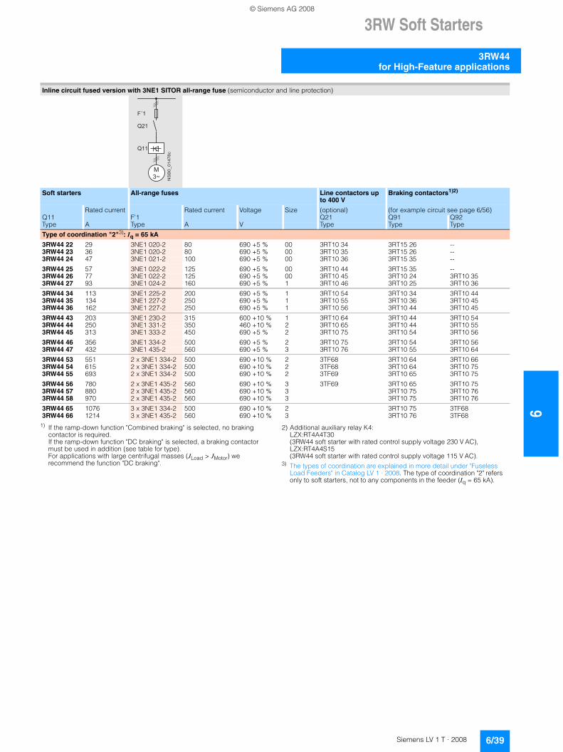
3RW Soft Starters
6/39Siemens LV 1 T · 2008
6
3RW44for High-Feature applications
1) If the ramp-down function "Combined braking" is selected, no braking contactor is required. If the ramp-down function "DC braking" is selected, a braking contactor must be used in addition (see table for type). For applications with large centrifugal masses (JLoad > JMotor) we recommend the function "DC braking".
2) Additional auxiliary relay K4: LZX:RT4A4T30 (3RW44 soft starter with rated control supply voltage 230 V AC), LZX:RT4A4S15 (3RW44 soft starter with rated control supply voltage 115 V AC).
3) The types of coordination are explained in more detail under "Fuseless Load Feeders" in Catalog LV 1 · 2008. The type of coordination "2" refers only to soft starters, not to any components in the feeder (Iq = 65 kA).
Inline circuit fused version with 3NE1 SITOR all-range fuse (semiconductor and line protection)
Soft starters All-range fuses Line contactors up to 400 V
Braking contactors1)2)
Rated current Rated current Voltage Size (optional) (for example circuit see page 6/56)Q11 F'1 Q21 Q91 Q92Type A Type A V Type Type Type
Type of coordination "2"3): Iq = 65 kA
3RW44 22 29 3NE1 020-2 80 690 +5 % 00 3RT10 34 3RT15 26 --3RW44 23 36 3NE1 020-2 80 690 +5 % 00 3RT10 35 3RT15 26 --3RW44 24 47 3NE1 021-2 100 690 +5 % 00 3RT10 36 3RT15 35 --
3RW44 25 57 3NE1 022-2 125 690 +5 % 00 3RT10 44 3RT15 35 --3RW44 26 77 3NE1 022-2 125 690 +5 % 00 3RT10 45 3RT10 24 3RT10 353RW44 27 93 3NE1 024-2 160 690 +5 % 1 3RT10 46 3RT10 25 3RT10 36
3RW44 34 113 3NE1 225-2 200 690 +5 % 1 3RT10 54 3RT10 34 3RT10 443RW44 35 134 3NE1 227-2 250 690 +5 % 1 3RT10 55 3RT10 36 3RT10 453RW44 36 162 3NE1 227-2 250 690 +5 % 1 3RT10 56 3RT10 44 3RT10 45
3RW44 43 203 3NE1 230-2 315 600 +10 % 1 3RT10 64 3RT10 44 3RT10 543RW44 44 250 3NE1 331-2 350 460 +10 % 2 3RT10 65 3RT10 44 3RT10 553RW44 45 313 3NE1 333-2 450 690 +5 % 2 3RT10 75 3RT10 54 3RT10 56
3RW44 46 356 3NE1 334-2 500 690 +5 % 2 3RT10 75 3RT10 54 3RT10 563RW44 47 432 3NE1 435-2 560 690 +5 % 3 3RT10 76 3RT10 55 3RT10 64
3RW44 53 551 2 x 3NE1 334-2 500 690 +10 % 2 3TF68 3RT10 64 3RT10 663RW44 54 615 2 x 3NE1 334-2 500 690 +10 % 2 3TF68 3RT10 64 3RT10 753RW44 55 693 2 x 3NE1 334-2 500 690 +10 % 2 3TF69 3RT10 65 3RT10 75
3RW44 56 780 2 x 3NE1 435-2 560 690 +10 % 3 3TF69 3RT10 65 3RT10 753RW44 57 880 2 x 3NE1 435-2 560 690 +10 % 3 3RT10 75 3RT10 763RW44 58 970 2 x 3NE1 435-2 560 690 +10 % 3 3RT10 75 3RT10 76
3RW44 65 1076 3 x 3NE1 334-2 500 690 +10 % 2 3RT10 75 3TF683RW44 66 1214 3 x 3NE1 435-2 560 690 +10 % 3 3RT10 76 3TF68
�����������
� �
� � �
� � �
� �
© Siemens AG 2008
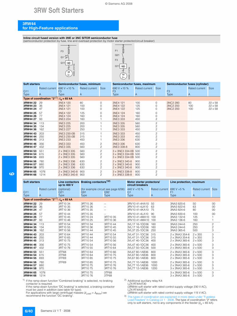
63RW Soft Starters
3RW44 for High-Feature applications
6/40 Siemens LV 1 T · 2008
1) If the ramp-down function "Combined braking" is selected, no braking contactor is required. If the ramp-down function "DC braking" is selected, a braking contactor must be used in addition (see table for type). For applications with large centrifugal masses (JLoad > JMotor) we recommend the function "DC braking".
2) Additional auxiliary relay K4: LZX:RT4A4T30 (3RW44 soft starter with rated control supply voltage 230 V AC), LZX:RT4A4S15 (3RW44 soft starter with rated control supply voltage 115 V AC).
3) The types of coordination are explained in more detail under "Fuseless Load Feeders" in Catalog LV 1 · 2008. The type of coordination "2" refers only to soft starters, not to any components in the feeder (Iq = 65 kA).
Inline circuit fused version with 3NE or 3NC SITOR semiconductor fuse(semiconductor protection by fuse, line and overload protection by motor starter protector/circuit breaker)
Soft starters Semiconductor fuses, minimum Semiconductor fuses, maximum Semiconductor fuses (cylinder)
Rated current 690 V +10 % Rated current Size 690 V +10 % Rated current Size Rated current SizeQ11 F3 F3 F3Type A Type A Type A Type A
Type of coordination "2"3): Iq = 65 kA
3RW44 22 29 3NE4 120 80 0 3NE4 121 100 0 3NC2 280 80 22 x 583RW44 23 36 3NE4 121 100 0 3NE4 122 125 0 3NC2 200 100 22 x 583RW44 24 47 3NE4 121 100 0 3NE4 122 125 0 3NC2 200 100 22 x 58
3RW44 25 57 3NE4 122 125 0 3NE4 124 160 03RW44 26 77 3NE4 124 160 0 3NE4 124 160 03RW44 27 93 3NE3 224 160 1 3NE3 333 450 2
3RW44 34 113 3NE3 225 200 1 3NE3 335 560 23RW44 35 134 3NE3 225 200 1 3NE3 335 560 23RW44 36 162 3NE3 227 250 1 3NE3 333 450 2
3RW44 43 203 3NE3 230-0B 315 1 3NE3 333 450 23RW44 44 250 3NE3 230-0B 315 1 3NE3 333 450 23RW44 45 313 3NE3 233 450 1 3NE3 336 630 2
3RW44 46 356 3NE3 333 450 2 3NE3 336 630 23RW44 47 432 3NE3 335 560 2 3NE3 338-8 800 2
3RW44 53 551 2 x 3NE3 335 560 2 3 x 3NE3 334-0B 500 23RW44 54 615 2 x 3NE3 335 560 2 3 x 3NE3 334-0B 500 23RW44 55 693 2 x 3NE3 335 560 2 3 x 3NE3 334-0B 500 2
3RW44 56 780 2 x 3NE3 336 630 2 2 x 3NE3 340-8 900 23RW44 57 880 2 x 3NE3 336 630 2 2 x 3NE3 340-8 900 23RW44 58 970 2 x 3NE3 336 630 2 2 x 3NE3 340-8 900 2
3RW44 65 1076 2 x 3NE3 340-8 900 2 3 x 3NE3 338-8 800 23RW44 66 1214 2 x 3NE3 340-8 900 2 3 x 3NE3 338-8 800 2
Soft starters Line contactors up to 400 V
Braking contactors1)2) Motor starter protectors/circuit breakers
Line protection, maximum
Rated current (optional) (for example circuit see page 6/56) 440 V +10 % Rated current 690 V +5 % Rated current SizeQ11 Q21 Q91 Q92 Q1 F1Type A Type Type Type Type A Type A
Type of coordination "2"3): Iq = 65 kA
3RW44 22 29 3RT10 34 3RT15 26 -- 3RV10 41-4HA10 50 3NA3 820-6 50 003RW44 23 36 3RT10 35 3RT15 26 -- 3RV10 41-4JA10 63 3NA3 822-6 63 003RW44 24 47 3RT10 36 3RT15 35 -- 3RV10 41-4KA10 75 3NA3 824-6 80 00
3RW44 25 57 3RT10 44 3RT15 35 -- 3RV10 41-4LA10 90 3NA3 830-6 100 003RW44 26 77 3RT10 45 3RT10 24 3RT10 35 3RV10 41-4MA10 100 3NA3 132-6 125 13RW44 27 93 3RT10 46 3RT10 25 3RT10 36 3RV10 41-4MA10 100 3NA3 136-6 160 1
3RW44 34 113 3RT10 54 3RT10 34 3RT10 44 3VL17 16-1DD36 160 3NA3 244-6 250 23RW44 35 134 3RT10 55 3RT10 36 3RT10 45 3VL17 16-1DD36 160 3NA3 244-6 250 23RW44 36 162 3RT10 56 3RT10 44 3RT10 45 3VL37 25-1DC36 250 3NA3 365-6 500 3
3RW44 43 203 3RT10 64 3RT10 44 3RT10 54 3VL47 31-1DC36 315 2 x 3NA3 354-6 2 x 355 33RW44 44 250 3RT10 65 3RT10 44 3RT10 55 3VL47 31-1DC36 315 2 x 3NA3 354-6 2 x 355 33RW44 45 313 3RT10 75 3RT10 54 3RT10 56 3VL47 40-1DC36 400 2 x 3NA3 365-6 2 x 500 3
3RW44 46 356 3RT10 75 3RT10 54 3RT10 56 3VL47 40-1DC36 400 2 x 3NA3 365-6 2 x 500 33RW44 47 432 3RT10 76 3RT10 55 3RT10 64 3VL57 50-1DC36 500 2 x 3NA3 365-6 2 x 500 3
3RW44 53 551 3TF68 3RT10 64 3RT10 66 3VL67 80-1AB36 800 2 x 3NA3 365-6 2 x 500 33RW44 54 615 3TF68 3RT10 64 3RT10 75 3VL67 80-1AB36 800 2 x 3NA3 365-6 2 x 500 33RW44 55 693 3TF69 3RT10 65 3RT10 75 3VL67 80-1AB36 800 2 x 3NA3 365-6 2 x 500 3
3RW44 56 780 3TF69 3RT10 65 3RT10 75 3VL77 10-1AB36 1000 2 x 3NA3 365-6 2 x 500 33RW44 57 880 3RT10 75 3RT10 76 3VL77 10-1AB36 1000 2 x 3NA3 365-6 2 x 500 33RW44 58 970 3RT10 75 3RT10 76 3VL77 12-1AB36 1200 3 x 3NA3 365-6 3 x 500 3
3RW44 65 1076 3RT10 75 3TF68 3 x 3NA3 365-6 3 x 500 33RW44 66 1214 3RT10 76 3TF68 3 x 3NA3 365-6 3 x 500 3
�
����������
� � �
� �
� �
�
����������
� �
� � �
� � �
�
© Siemens AG 2008
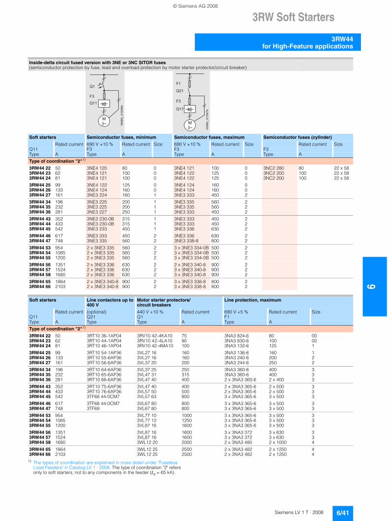
3RW Soft Starters
6/41Siemens LV 1 T · 2008
6
3RW44for High-Feature applications
1) The types of coordination are explained in more detail under "Fuseless Load Feeders" in Catalog LV 1 · 2008. The type of coordination "2" refers only to soft starters, not to any components in the feeder (Iq = 65 kA).
Inside-delta circuit fused version with 3NE or 3NC SITOR fuses(semiconductor protection by fuse, lead and overload protection by motor starter protector/circuit breaker)
Soft starters Semiconductor fuses, minimum Semiconductor fuses, maximum Semiconductor fuses (cylinder)
Rated current 690 V +10 % Rated current Size 690 V +10 % Rated current Size Rated current SizeQ11 F3 F3 F3Type A Type A Type A Type A
Type of coordination "2"1)
3RW44 22 50 3NE4 120 80 0 3NE4 121 100 0 3NC2 280 80 22 x 583RW44 23 62 3NE4 121 100 0 3NE4 122 125 0 3NC2 200 100 22 x 583RW44 24 81 3NE4 121 100 0 3NE4 122 125 0 3NC2 200 100 22 x 58
3RW44 25 99 3NE4 122 125 0 3NE4 124 160 03RW44 26 133 3NE4 124 160 0 3NE4 124 160 03RW44 27 161 3NE3 224 160 1 3NE3 333 450 2
3RW44 34 196 3NE3 225 200 1 3NE3 335 560 23RW44 35 232 3NE3 225 200 1 3NE3 335 560 23RW44 36 281 3NE3 227 250 1 3NE3 333 450 2
3RW44 43 352 3NE3 230-0B 315 1 3NE3 333 450 23RW44 44 433 3NE3 230-0B 315 1 3NE3 333 450 23RW44 45 542 3NE3 233 450 1 3NE3 336 630 2
3RW44 46 617 3NE3 333 450 2 3NE3 336 630 23RW44 47 748 3NE3 335 560 2 3NE3 338-8 800 2
3RW44 53 954 2 x 3NE3 335 560 2 3 x 3NE3 334-0B 500 23RW44 54 1065 2 x 3NE3 335 560 2 3 x 3NE3 334-0B 500 23RW44 55 1200 2 x 3NE3 335 560 2 3 x 3NE3 334-0B 500 2
3RW44 56 1351 2 x 3NE3 336 630 2 2 x 3NE3 340-8 900 23RW44 57 1524 2 x 3NE3 336 630 2 3 x 3NE3 340-8 900 23RW44 58 1680 2 x 3NE3 336 630 2 3 x 3NE3 340-8 900 2
3RW44 65 1864 2 x 3NE3 340-8 900 2 3 x 3NE3 338-8 800 23RW44 66 2103 2 x 3NE3 340-8 900 2 3 x 3NE3 338-8 800 2
Soft starters Line contactors up to 400 V
Motor starter protectors/circuit breakers
Line protection, maximum
Rated current (optional) 440 V +10 % Rated current 690 V +5 % Rated current SizeQ11 Q21 Q1 F1Type A Type Type A Type A
Type of coordination "2"1)
3RW44 22 50 3RT10 36-1AP04 3RV10 42-4KA10 75 3NA3 824-6 80 003RW44 23 62 3RT10 44-1AP04 3RV10 42-4LA10 90 3NA3 830-6 100 003RW44 24 81 3RT10 46-1AP04 3RV10 42-4MA10 100 3NA3 132-6 125 1
3RW44 25 99 3RT10 54-1AP36 3VL27 16 160 3NA3 136-6 160 13RW44 26 133 3RT10 55-6AP36 3VL27 16 160 3NA3 240-6 200 23RW44 27 161 3RT10 56-6AP36 3VL37 20 200 3NA3 244-6 250 2
3RW44 34 196 3RT10 64-6AP36 3VL37 25 250 3NA3 360-6 400 33RW44 35 232 3RT10 65-6AP36 3VL47 31 315 3NA3 360-6 400 33RW44 36 281 3RT10 66-6AP36 3VL47 40 400 2 x 3NA3 360-6 2 x 400 3
3RW44 43 352 3RT10 75-6AP36 3VL47 40 400 2 x 3NA3 365-6 2 x 500 33RW44 44 433 3RT10 76-6AP36 3VL57 50 500 2 x 3NA3 365-6 2 x 500 33RW44 45 542 3TF68 44-0CM7 3VL57 63 800 3 x 3NA3 365-6 3 x 500 3
3RW44 46 617 3TF68 44-0CM7 3VL67 80 800 3 x 3NA3 365-6 3 x 500 33RW44 47 748 3TF69 3VL67 80 800 3 x 3NA3 365-6 3 x 500 3
3RW44 53 954 3VL77 10 1000 3 x 3NA3 365-6 3 x 500 33RW44 54 1065 3VL77 12 1250 3 x 3NA3 365-6 3 x 500 33RW44 55 1200 3VL87 16 1600 3 x 3NA3 365-6 3 x 500 3
3RW44 56 1351 3VL87 16 1600 3 x 3NA3 372 3 x 630 33RW44 57 1524 3VL87 16 1600 3 x 3NA3 372 3 x 630 33RW44 58 1680 3WL12 20 2000 2 x 3NA3 480 2 x 1000 4
3RW44 65 1864 3WL12 25 2500 2 x 3NA3 482 2 x 1250 43RW44 66 2103 3WL12 25 2500 2 x 3NA3 482 2 x 1250 4
�
����������
� � �
� �
� �
�
����������
� �
� � �
� � �
�
© Siemens AG 2008
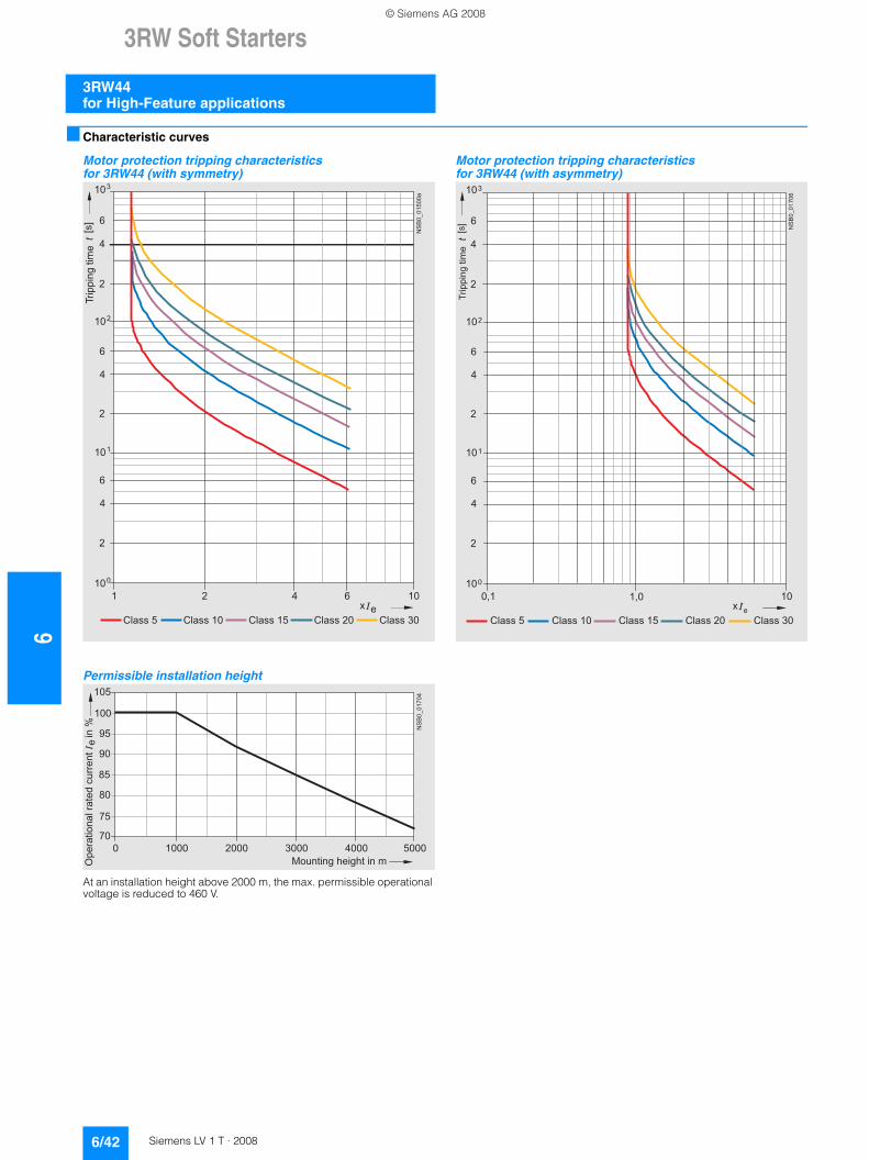
63RW Soft Starters
3RW44 for High-Feature applications
6/42 Siemens LV 1 T · 2008
■ Characteristic curves
Motor protection tripping characteristics for 3RW44 (with symmetry)
Permissible installation height
At an installation height above 2000 m, the max. permissible operational voltage is reduced to 460 V.
Motor protection tripping characteristics for 3RW44 (with asymmetry)
e2 4 6 101
Class 10 Class 15 Class 20
100
101
102
103
2
4
6
2
4
6
2
4
6
Class 5 Class 30
NS
B0_
0150
0a
[s]
x
Trip
ping
tim
e
85
105
70
75
80
90
95
100
NS
B0_
0170
4
0 1000 2000 3000 4000 5000
Ope
ratio
nal r
ated
cur
rent
I i
n %
Mounting height in m
e
e
100,1
Class 10 Class 15 Class 20
100
101
102
103
2
4
6
2
4
6
2
4
6
Class 5 Class 30
NS
B0_
0170
6
[s]
x1,0
Trip
ping
tim
e
© Siemens AG 2008
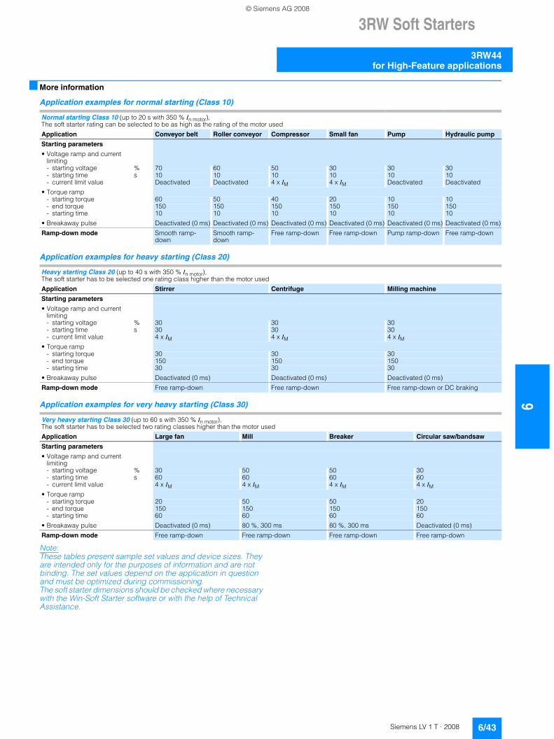
3RW Soft Starters
6/43Siemens LV 1 T · 2008
6
3RW44for High-Feature applications
■ More information
Application examples for normal starting (Class 10)
Application examples for heavy starting (Class 20)
Application examples for very heavy starting (Class 30)
Note:These tables present sample set values and device sizes. They are intended only for the purposes of information and are not binding. The set values depend on the application in question and must be optimized during commissioning. The soft starter dimensions should be checked where necessary with the Win-Soft Starter software or with the help of Technical Assistance.
Normal starting Class 10 (up to 20 s with 350 % In motor), The soft starter rating can be selected to be as high as the rating of the motor used
Application Conveyor belt Roller conveyor Compressor Small fan Pump Hydraulic pump
Starting parameters
• Voltage ramp and current limiting- starting voltage % 70 60 50 30 30 30- starting time s 10 10 10 10 10 10- current limit value Deactivated Deactivated 4 x IM 4 x IM Deactivated Deactivated
• Torque ramp- starting torque 60 50 40 20 10 10- end torque 150 150 150 150 150 150- starting time 10 10 10 10 10 10
• Breakaway pulse Deactivated (0 ms) Deactivated (0 ms) Deactivated (0 ms) Deactivated (0 ms) Deactivated (0 ms) Deactivated (0 ms)
Ramp-down mode Smooth ramp-down
Smooth ramp-down
Free ramp-down Free ramp-down Pump ramp-down Free ramp-down
Heavy starting Class 20 (up to 40 s with 350 % In motor), The soft starter has to be selected one rating class higher than the motor used
Application Stirrer Centrifuge Milling machine
Starting parameters
• Voltage ramp and current limiting- starting voltage % 30 30 30- starting time s 30 30 30- current limit value 4 x IM 4 x IM 4 x IM
• Torque ramp- starting torque 30 30 30- end torque 150 150 150- starting time 30 30 30
• Breakaway pulse Deactivated (0 ms) Deactivated (0 ms) Deactivated (0 ms)
Ramp-down mode Free ramp-down Free ramp-down Free ramp-down or DC braking
Very heavy starting Class 30 (up to 60 s with 350 % In motor), The soft starter has to be selected two rating classes higher than the motor used
Application Large fan Mill Breaker Circular saw/bandsaw
Starting parameters
• Voltage ramp and current limiting- starting voltage % 30 50 50 30- starting time s 60 60 60 60- current limit value 4 x IM 4 x IM 4 x IM 4 x IM
• Torque ramp- starting torque 20 50 50 20- end torque 150 150 150 150- starting time 60 60 60 60
• Breakaway pulse Deactivated (0 ms) 80 %, 300 ms 80 %, 300 ms Deactivated (0 ms)
Ramp-down mode Free ramp-down Free ramp-down Free ramp-down Free ramp-down
© Siemens AG 2008
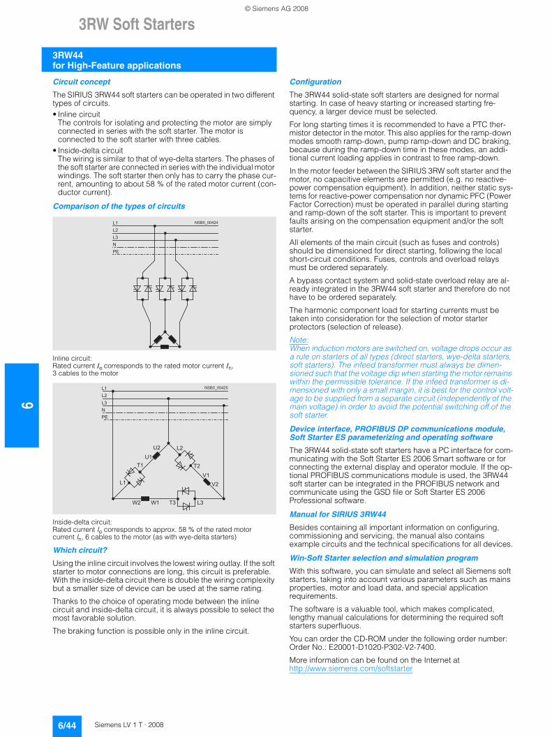
63RW Soft Starters
3RW44 for High-Feature applications
6/44 Siemens LV 1 T · 2008
Circuit concept
The SIRIUS 3RW44 soft starters can be operated in two different types of circuits.• Inline circuit
The controls for isolating and protecting the motor are simply connected in series with the soft starter. The motor is connected to the soft starter with three cables.
• Inside-delta circuit The wiring is similar to that of wye-delta starters. The phases of the soft starter are connected in series with the individual motor windings. The soft starter then only has to carry the phase cur-rent, amounting to about 58 % of the rated motor current (con-ductor current).
Comparison of the types of circuits
Inline circuit:Rated current Ie corresponds to the rated motor current In,3 cables to the motor
Inside-delta circuit:Rated current Ie corresponds to approx. 58 % of the rated motor current In, 6 cables to the motor (as with wye-delta starters)
Which circuit?
Using the inline circuit involves the lowest wiring outlay. If the soft starter to motor connections are long, this circuit is preferable. With the inside-delta circuit there is double the wiring complexity but a smaller size of device can be used at the same rating.
Thanks to the choice of operating mode between the inline circuit and inside-delta circuit, it is always possible to select the most favorable solution.
The braking function is possible only in the inline circuit.
Configuration
The 3RW44 solid-state soft starters are designed for normal starting. In case of heavy starting or increased starting fre-quency, a larger device must be selected.
For long starting times it is recommended to have a PTC ther-mistor detector in the motor. This also applies for the ramp-down modes smooth ramp-down, pump ramp-down and DC braking, because during the ramp-down time in these modes, an addi-tional current loading applies in contrast to free ramp-down.
In the motor feeder between the SIRIUS 3RW soft starter and the motor, no capacitive elements are permitted (e.g. no reactive-power compensation equipment). In addition, neither static sys-tems for reactive-power compensation nor dynamic PFC (Power Factor Correction) must be operated in parallel during starting and ramp-down of the soft starter. This is important to prevent faults arising on the compensation equipment and/or the soft starter.
All elements of the main circuit (such as fuses and controls) should be dimensioned for direct starting, following the local short-circuit conditions. Fuses, controls and overload relays must be ordered separately.
A bypass contact system and solid-state overload relay are al-ready integrated in the 3RW44 soft starter and therefore do not have to be ordered separately.
The harmonic component load for starting currents must be taken into consideration for the selection of motor starter protectors (selection of release).
Note:When induction motors are switched on, voltage drops occur as a rule on starters of all types (direct starters, wye-delta starters, soft starters). The infeed transformer must always be dimen-sioned such that the voltage dip when starting the motor remains within the permissible tolerance. If the infeed transformer is di-mensioned with only a small margin, it is best for the control volt-age to be supplied from a separate circuit (independently of the main voltage) in order to avoid the potential switching off of the soft starter.
Device interface, PROFIBUS DP communications module, Soft Starter ES parameterizing and operating software
The 3RW44 solid-state soft starters have a PC interface for com-municating with the Soft Starter ES 2006 Smart software or for connecting the external display and operator module. If the op-tional PROFIBUS communications module is used, the 3RW44 soft starter can be integrated in the PROFIBUS network and communicate using the GSD file or Soft Starter ES 2006 Professional software.
Manual for SIRIUS 3RW44
Besides containing all important information on configuring, commissioning and servicing, the manual also contains example circuits and the technical specifications for all devices.
Win-Soft Starter selection and simulation program
With this software, you can simulate and select all Siemens soft starters, taking into account various parameters such as mains properties, motor and load data, and special application requirements.
The software is a valuable tool, which makes complicated, lengthy manual calculations for determining the required soft starters superfluous.
You can order the CD-ROM under the following order number: Order No.: E20001-D1020-P302-V2-7400.
More information can be found on the Internet at http://www.siemens.com/softstarter
� � � � � � � � � �� �
� �
� �
�
� �
� � � � � � � � � �� �
� �
� �
�
� �
� � � � � � � �
� �
� �
� �
� �
� �
� �
� �
� �
© Siemens AG 2008
3RW Soft Starters
6/45Siemens LV 1 T · 2008
6
3RW44for High-Feature applications
SIRIUS soft starter training course (SD-SIRIUSO)
Siemens offers a 2-day training course on the SIRIUS solid-state soft starters to keep customers and own personnel up-to-date on configuring, commissioning and servicing issues.
Please direct enquiries and applications to:
Siemens AG A&D Information and Training Center Gleiwitzer Strasse 555 D-90475 Nürnberg Telephone: +49 911 895 3202 Telefax: +49 911 895 3275 E-mail: [email protected] http://www.siemens.com/sitrain-cd
© Siemens AG 2008
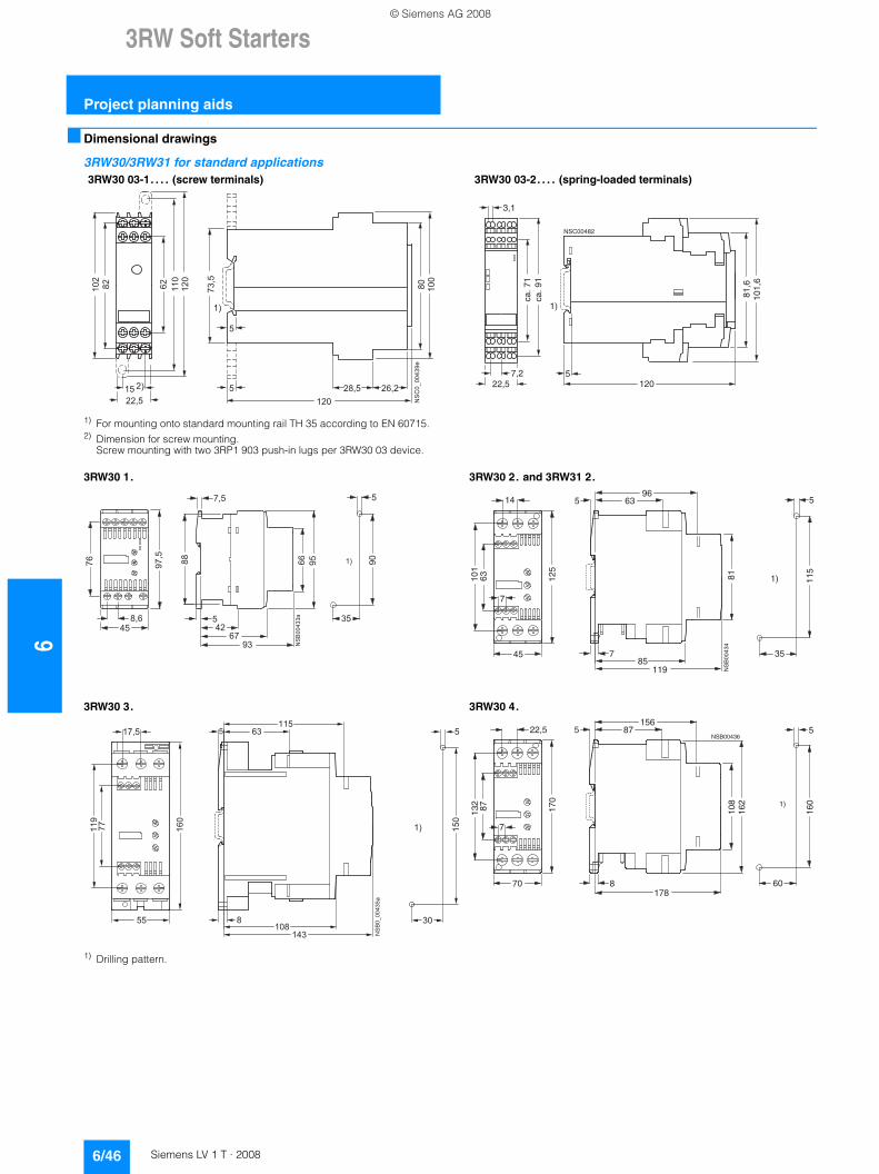
63RW Soft Starters
Project planning aids
6/46 Siemens LV 1 T · 2008
■ Dimensional drawings
3RW30/3RW31 for standard applications
1) Drilling pattern.
3RW30 03-1. . . . (screw terminals) 3RW30 03-2. . . . (spring-loaded terminals)
��
����
�����������
���
��
���
� �
� � � �
� � � �� � � �
� � �
���
��
���
�
�
��
5
NSC00482
101,
6
ca. 7
1
7,2
ca. 9
1
81,6
120
1)
3,1
22,5
1) For mounting onto standard mounting rail TH 35 according to EN 60715.2) Dimension for screw mounting.
Screw mounting with two 3RP1 903 push-in lugs per 3RW30 03 device.
3RW30 1. 3RW30 2. and 3RW31 2.
3RW30 3. 3RW30 4.
��
��
��
���
��
�
��
��
��
�
��
��
� ��
��
�
��
1)
NS
B00
434
35
115
7
5
125
101
63
14
45
6396
5
785
119
81
� ����
� � � �
��
���
� �
� � � � �
� �
� �
�
���
�
� ��������
NSB00436
60
160
7
5
170
132
87
22,5
70
87156
5
8
108
162 1)
178
© Siemens AG 2008
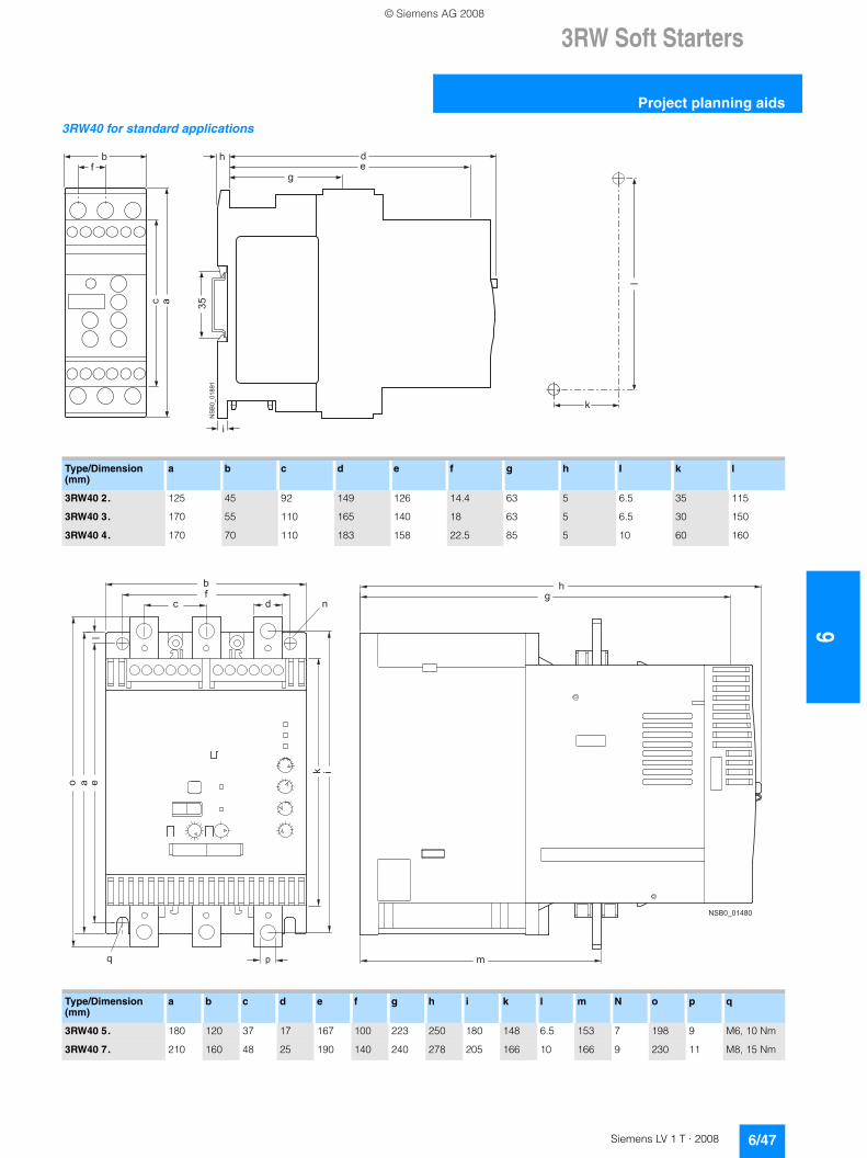
3RW Soft Starters
6/47Siemens LV 1 T · 2008
6
Project planning aids
3RW40 for standard applications
Type/Dimension (mm)
a b c d e f g h I k l
3RW40 2. 125 45 92 149 126 14.4 63 5 6.5 35 115
3RW40 3. 170 55 110 165 140 18 63 5 6.5 30 150
3RW40 4. 170 70 110 183 158 22.5 85 5 10 60 160
k
l
fb h d
eg
c a 35N
SB
0_01
891
i
Type/Dimension (mm)
a b c d e f g h i k l m N o p q
3RW40 5. 180 120 37 17 167 100 223 250 180 148 6.5 153 7 198 9 M6, 10 Nm
3RW40 7. 210 160 48 25 190 140 240 278 205 166 10 166 9 230 11 M8, 15 Nm
�
�� �
� � ��
��
��
�
�
� � � � � � � �
� �
© Siemens AG 2008
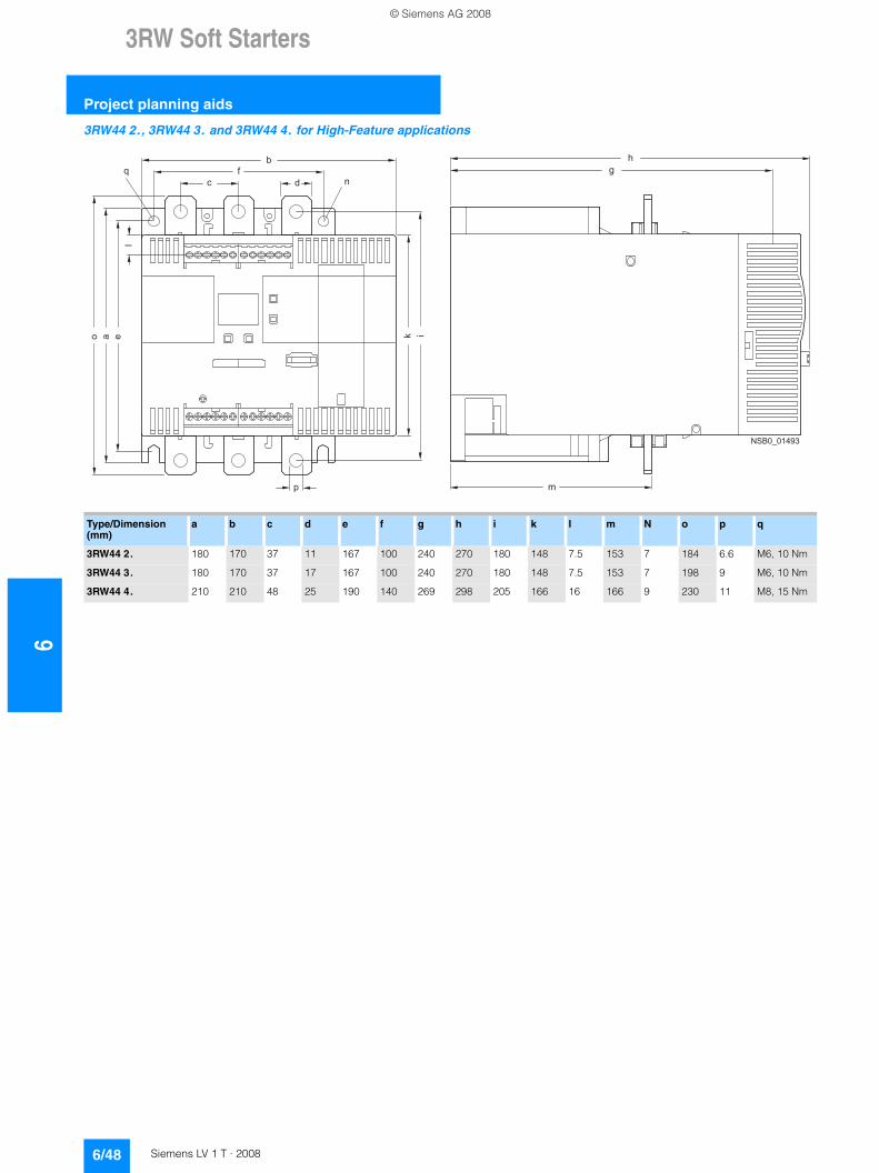
63RW Soft Starters
Project planning aids
6/48 Siemens LV 1 T · 2008
3RW44 2., 3RW44 3. and 3RW44 4. for High-Feature applications�
�
�
�
�
� ��
�
�
�
�
� ��
� � � � � � � �
�
Type/Dimension (mm)
a b c d e f g h i k l m N o p q
3RW44 2. 180 170 37 11 167 100 240 270 180 148 7.5 153 7 184 6.6 M6, 10 Nm
3RW44 3. 180 170 37 17 167 100 240 270 180 148 7.5 153 7 198 9 M6, 10 Nm
3RW44 4. 210 210 48 25 190 140 269 298 205 166 16 166 9 230 11 M8, 15 Nm
© Siemens AG 2008
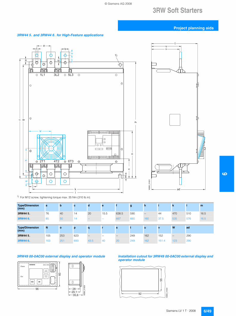
3RW Soft Starters
6/49Siemens LV 1 T · 2008
6
Project planning aids
3RW44 5. and 3RW44 6. for High-Feature applications
1) For M12 screw, tightening torque max. 35 Nm (310 lb.in).
3RW49 00-0AC00 external display and operator module Installation cutout for 3RW49 00-0AC00 external display and operator module
rs
w
qh
NS
B0_
0183
1
ad
tuv
p
no
m
a
ikl
e d
b
1)
c
f g
6T34T22T1
5L33L21L1
Type/Dimension (mm)
a b c d e f g h i k l m
3RW44 5. 76 40 14 20 15.5 638.5 590 -- 44 470 510 16.5
3RW44 6. 85 50 14 -- -- 667 660 160 37.5 535 576 16.5
Type/Dimension (mm)
N o p q r s t u v W ad
3RW44 5. 105 253 623 -- -- -- 249 162 152 -- 290
3RW44 6. 103 251 693 43.5 40 20 249 162 151.4 123 290
SIRIUS 3RW44
DEVICE
SF
60
NS
B0_
0182
9
96 2829,135,6
NS
B0_
0183
0
92
55
© Siemens AG 2008
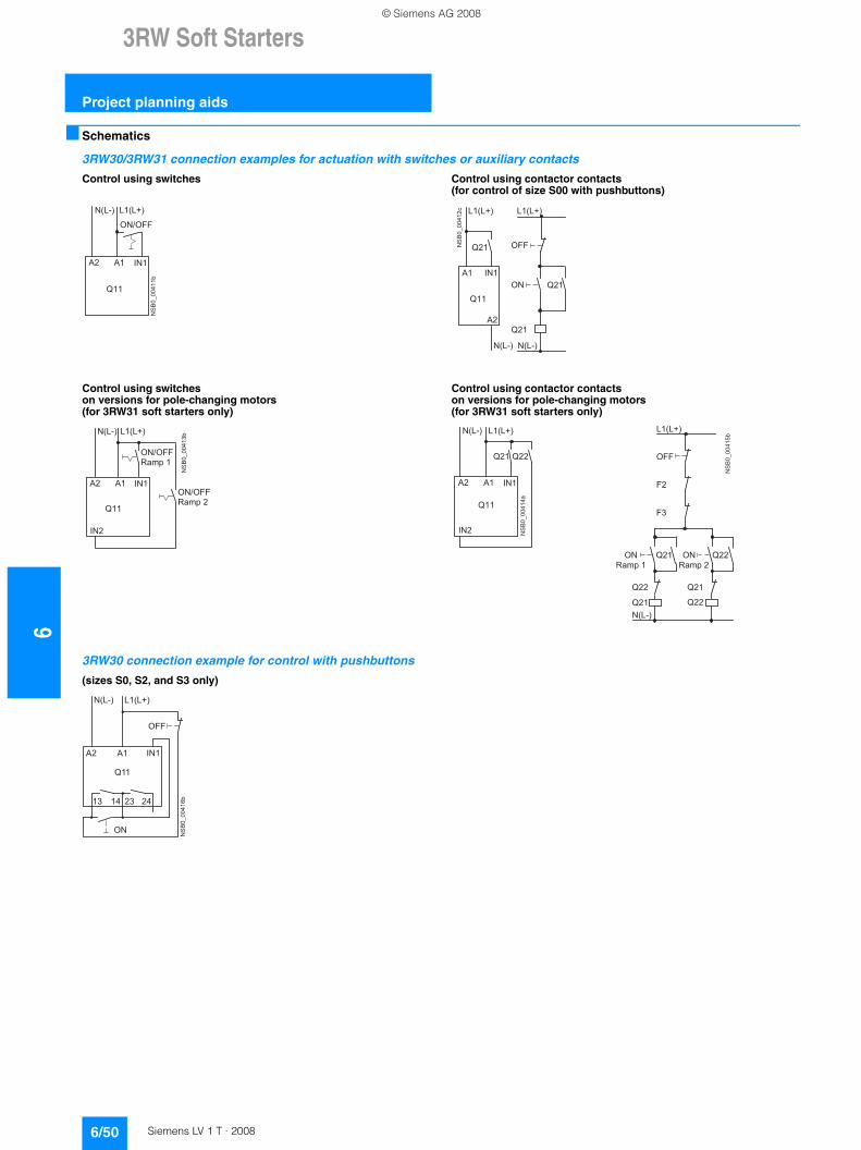
63RW Soft Starters
Project planning aids
6/50 Siemens LV 1 T · 2008
■ Schematics
3RW30/3RW31 connection examples for actuation with switches or auxiliary contacts
3RW30 connection example for control with pushbuttons
Control using switches Control using contactor contacts(for control of size S00 with pushbuttons)
Control using switches on versions for pole-changing motors (for 3RW31 soft starters only)
Control using contactor contacts on versions for pole-changing motors (for 3RW31 soft starters only)
(sizes S0, S2, and S3 only)
� ���������
� ! " "
# � $ # % �� $ # & �
' ( ' � ) � �
� � �
� �������(� # � $ # % �
�
" "
) � �
' (
' �
� $ # & �
* ( �
* ( �
* ( �
# � $ # % �
� $ # & �
� � �
� ��������# � $ # % �
� ! " "
+ � � � , �
� ! " "
+ � � � , (
� $ # & �
' ( ' � ) � �
) � (
� � �
� ���������
# � $ # % �� $ # & �
* ( � * ( (
' ( ' � ) � �
) � (
� � �
� ���������
" "
" (
"
�
, , , , + � � � , (
* ( ( � ,
+ � � � , �
* ( �
* ( � * ( (
* ( ( * ( �
# � $ # % �
� $ # & �
NS
B0_
0041
6b
N(L-) L1(L+)
A2 A1 IN1
Q11
13 14 24
ON
OFF
23
© Siemens AG 2008
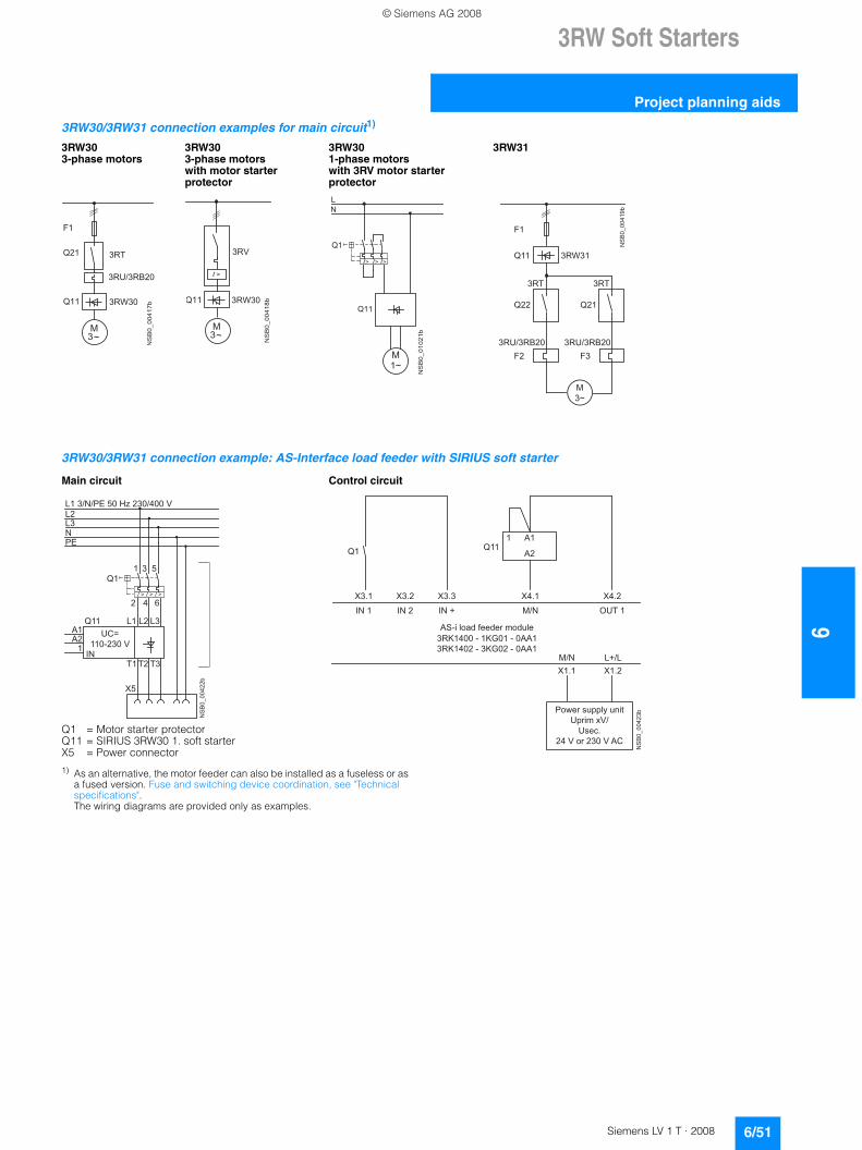
3RW Soft Starters
6/51Siemens LV 1 T · 2008
6
Project planning aids
3RW30/3RW31 connection examples for main circuit1)
3RW30/3RW31 connection example: AS-Interface load feeder with SIRIUS soft starter
1) As an alternative, the motor feeder can also be installed as a fuseless or as a fused version. Fuse and switching device coordination, see "Technical specifications". The wiring diagrams are provided only as examples.
3RW30 3-phase motors
3RW303-phase motorswith motor starter protector
3RW301-phase motorswith 3RV motor starter protector
3RW31
Main circuit Control circuit
Q1 = Motor starter protectorQ11 = SIRIUS 3RW30 1. soft starterX5 = Power connector
" �
� ���������
- .
+ /* ( �
+ 0 ! + � ( �
+ 1 �� � �
� ��������
+ 2
3
- .
+ 1 �� � �
� ������(��
#
�
* � �
* �
3 3 3� � �
-
� .
NS
B0_
0041
9b
3RT
M3~
Q11
3RU/3RB20
3RW31
F1
F2 F3
Q22 Q21
3RT
3RU/3RB20
NS
B0_
0042
2b
UC=110-230 V
Q11
L1 3/N/PE 50 Hz 230/400 VL2L3NPE
Q11 3 5
2 4 6
L1 L2 L3A1A2
1
T1 T2 T3
X5
IN
NS
B0_
0042
3bPower supply unitUprim xV/
Usec.24 V or 230 V AC
AS-i load feeder module
Q11Q1A1
A2
1
IN 1 IN 2 IN + M/N OUT 1
X3.1 X3.2 X3.3 X4.1 X4.2
3RK1400 - 1KG01 - 0AA13RK1402 - 3KG02 - 0AA1
M/NX1.1 X1.2
L+/L
© Siemens AG 2008

63RW Soft Starters
Project planning aids
6/52 Siemens LV 1 T · 2008
1) Caution: Risk of restartingWhen operating with a switch (ON/OFF) a new, automatic restart will take place automatically if the start command is still active at terminal 1.
3RW40 2. ... 3RW40 4. connection examples for control circuit
Control using switches With remote reset Automatic mode
Control of 3RW40 2. ... 3RW40 4. by pushbutton
Connection example of 3RW40 2. ... 3RW40 4. for PTC sensors (thermistor motor protection)Thermoclick PTC type A
A2
ON/OFF
L1 (L +)N(L-)
1A1
Q11
NS
B0_
0191
4
1)
A2
ON/OFF
L1 (L +)N(L-)
1
RESET
A1
Q11
NS
B0_
0189
2
1)
A2 A1 1
ON/OFF
N(L-) L1(L+)
Q11
NS
B0_
0189
5
1)
NS
B0_
0191
5
>1,5 s
Us
100 %
t
>5 min
Us
ON
OFF t
NS
B0_
0191
6a
N(L-) L(L+)
NS
B0_
0189
6
A2A1 1
Q11
ON
ON
13 23
OFF
14 24NO NO
ϑ
T11/T21 T22T12
NS
B0_
0189
3
Q11
ϑ
T11/T21 T12 T22
NS
B0_
0189
4
Q11
© Siemens AG 2008
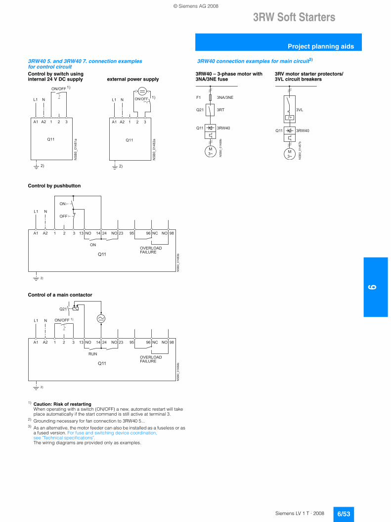
3RW Soft Starters
6/53Siemens LV 1 T · 2008
6
Project planning aids
1) Caution: Risk of restartingWhen operating with a switch (ON/OFF) a new, automatic restart will take place automatically if the start command is still active at terminal 3.
2) Grounding necessary for fan connection to 3RW40 5...3) As an alternative, the motor feeder can also be installed as a fuseless or as
a fused version. For fuse and switching device coordination, see "Technical specifications". The wiring diagrams are provided only as examples.
3RW40 5. and 3RW40 7. connection examples for control circuit
3RW40 connection examples for main circuit3)
Control by switch using internal 24 V DC supply external power supply
3RW40 – 3-phase motor with 3NA/3NE fuse
3RV motor starter protectors/3VL circuit breakers
Control by pushbutton
Control of a main contactor
# � �
' � ' ( � (
� ��������
� ! " "
( �
� �
� � �
' � ' ( � (
� ������(�
� ! " "� �
( �
# � �
� � �
NS
B0_
0148
9b
M3~
3RT
F1
Q11
Q21
3RW40
3NA/3NE
NS
B0_
0148
7b
M3~
3VL
Q11 3RW40
NS
B0_
0148
3b
NL1
A2A1 1
Q11
2 3
ON
2)
ON
13 23 95 96 98
OVERLOADFAILURE
OFF
14 24NO NO NC NO
NS
B0_
0148
4b
NL1
A2A1 1
Q11
2 3
2)
RUN
13 23 95 96 98
OVERLOADFAILURE
14 24NO NO NC NO
Q21
ON/OFF 1)
© Siemens AG 2008
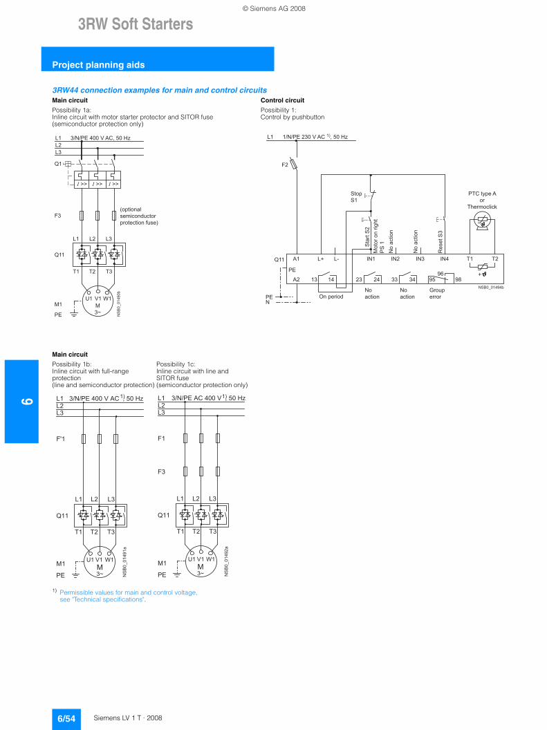
63RW Soft Starters
Project planning aids
6/54 Siemens LV 1 T · 2008
1) Permissible values for main and control voltage, see "Technical specifications".
3RW44 connection examples for main and control circuitsMain circuit Control circuit
Possibility 1a: Possibility 1:Inline circuit with motor starter protector and SITOR fuse (semiconductor protection only)
Control by pushbutton
Main circuit
Possibility 1b: Possibility 1c:Inline circuit with full-range protection (line and semiconductor protection)
Inline circuit with line and SITOR fuse (semiconductor protection only)
NS
B0_
0149
0b
(optionalsemiconductor protection fuse)
M3~
Q11
L1 3/N/PE 400 V AC, 50 HzL2L3
PE
L1 L2 L3
T1 T2 T3
Q1
F3
M1U1 V1 W1
NSB0_01494b
PE+
L1 1/N/PE 230 V AC 1), 50 Hz
PTC type Aor
Thermoclick
StopS1
On periodNoaction
Noaction
Grouperror
Mot
or o
n rig
htP
S 1
No
actio
n
No
actio
n
Q11
PE
IN1 T1 T2
F2
N
L+ L-A1 IN2 IN3 IN4
A2 13 14 23 24 33 34 95 9896
Sta
rt S
2
Res
et S
3
* � �
# � # ( #
/ � / ( /
- �
� ���������
" 4 �
2 �0 � 1 �
-
5 6 .
#
# (
# �� �
! � ! 5 6 , � � � , 2 , ' 7 , , � , � � , 8 9
* � �
"
# � # ( #
/ � / ( /
- �
� �������(�
" �
2 �0 � 1 �
-
5 6 .
#
# (
# � � � ! � ! 5 6 , ' 7 , � � � , 2 , , � , � � , 8 9
© Siemens AG 2008
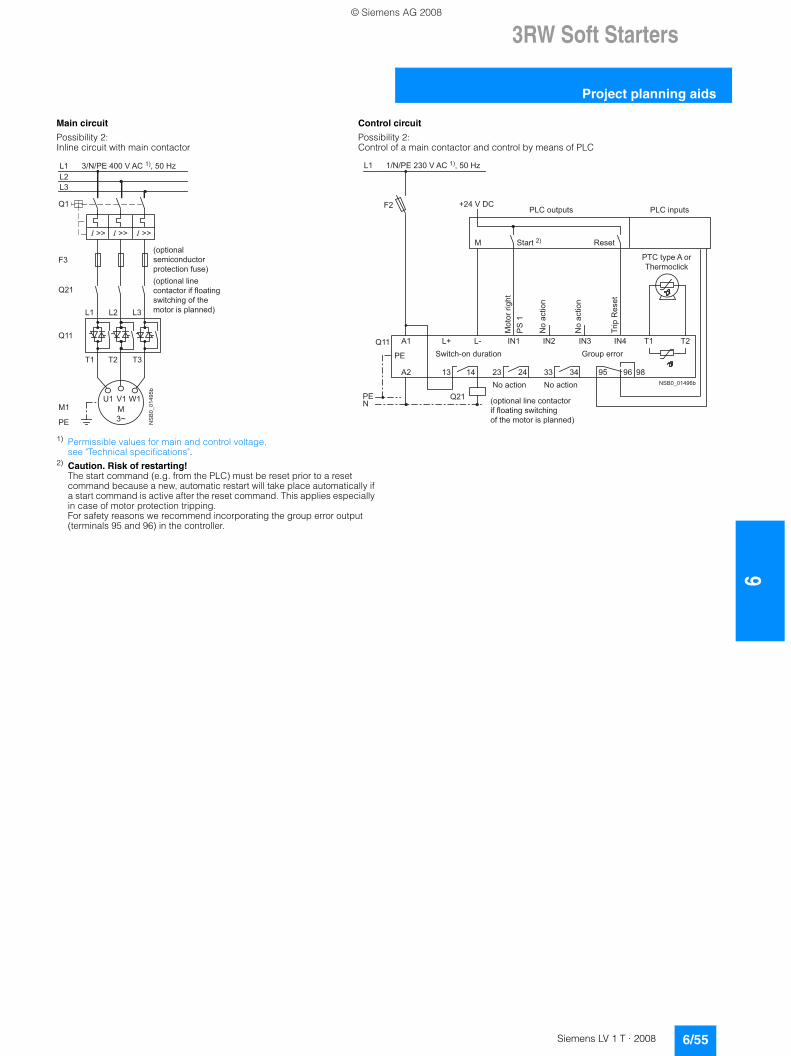
3RW Soft Starters
6/55Siemens LV 1 T · 2008
6
Project planning aids
1) Permissible values for main and control voltage, see "Technical specifications".
2) Caution. Risk of restarting!The start command (e.g. from the PLC) must be reset prior to a reset command because a new, automatic restart will take place automatically if a start command is active after the reset command. This applies especially in case of motor protection tripping.For safety reasons we recommend incorporating the group error output (terminals 95 and 96) in the controller.
Main circuit Control circuit
Possibility 2: Possibility 2:Inline circuit with main contactor Control of a main contactor and control by means of PLC
NS
B0_
0149
5b
(optionalsemiconductor protection fuse)(optional linecontactor if floatingswitching of themotor is planned)
L1 3/N/PE 400 V AC 1), 50 Hz
M3~
Q11
L2L3
PE
L1 L2 L3
T1 T2 T3
Q1
F3
M1U1 V1 W1
Q21
NSB0_01496b
+
L1 1/N/PE 230 V AC 1), 50 Hz
PTC type A orThermoclick
No action
Group error
Mot
or ri
ght
PS
1
No
actio
n
No
actio
n
No action
Switch-on duration
(optional line contactorif floating switching of the motor is planned)
PLC outputs PLC inputs
Trip
Res
et
Reset Start 2)
Q11
PE
IN1 T1 T2
F2
N
L+ L-A1 IN2 IN3 IN4
A2 13 14 23 24 33 34 95 9896
PE
Q21
+24 V DC
M
© Siemens AG 2008
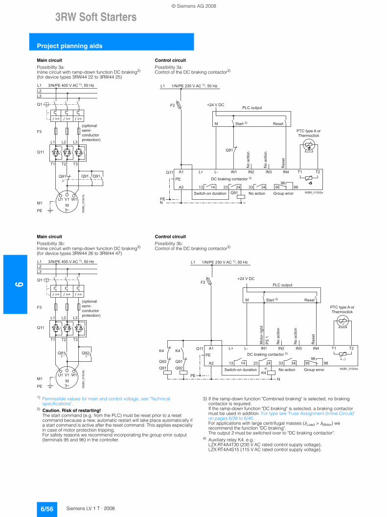
63RW Soft Starters
Project planning aids
6/56 Siemens LV 1 T · 2008
1) Permissible values for main and control voltage, see "Technical specifications".
2) Caution. Risk of restarting!The start command (e.g. from the PLC) must be reset prior to a reset command because a new, automatic restart will take place automatically if a start command is active after the reset command. This applies especially in case of motor protection tripping.For safety reasons we recommend incorporating the group error output (terminals 95 and 96) in the controller.
3) If the ramp-down function "Combined braking" is selected, no braking contactor is required. If the ramp-down function "DC braking" is selected, a braking contactor must be used in addition. For type see "Fuse Assignment (Inline Circuit)" on pages 6/38 to 6/40. For applications with large centrifugal masses (JLoad > JMotor) we recommend the function "DC braking".The output 2 must be switched over to "DC braking contactor".
4) Auxiliary relay K4, e.g.:LZX:RT4A4T30 (230 V AC rated control supply voltage), LZX:RT4A4S15 (115 V AC rated control supply voltage).
Main circuit Control circuit
Possibility 3a: Possibility 3a:Inline circuit with ramp-down function DC braking3)
(for device types 3RW44 22 to 3RW44 25)Control of the DC braking contactor3)
Main circuit Control circuit
Possibility 3b: Possibility 3b:Inline circuit with ramp-down function DC braking3)
(for device types 3RW44 26 to 3RW44 47)Control of the DC braking contactor3)
NS
B0_
0150
1bL1 3/N/PE 400 V AC 1), 50 Hz
(optionalsemi-conductorprotection)
M3~
Q11
L2L3
PE
L1 L2 L3
T1 T2 T3
Q1
F3
M1U1 V1 W1
Q912
Q91 Q91
NSB0_01502a
+
L1 1/N/PE 230 V AC 1), 50 Hz
PTC type A orThermoclick
No action Group error
No
actio
n
No
actio
n
Switch-on duration
PLC output
Res
et
Reset Start 2)
DC braking contactor 3)
Q11
PE
IN1 T1 T2
F2
N
L+ L-A1 IN2 IN3 IN4
A2 13 14 23 24 33 34 95 9896
PE
+24 V DC
M
Q91
Q91
NS
B0_
0150
3b
L1 3/N/PE 400 V AC 1), 50 Hz
(optionalsemi-conductorprotection)
M3~
Q11
L2L3
PE
L1 L2 L3
T1 T2 T3
Q1
F3
M1U1 V1 W1
Q92Q913 3
NSB0_01504a
+
L1 1/N/PE 230 V AC 1), 50 Hz
PTC type A orThermoclick
No action Group error
No
actio
n
No
actio
n
Switch-on duration
PLC output
Res
et
Reset Start 2)
DC braking contactor 3)
Mot
or ri
ght
PS
1
Q11
PE
IN1 T1 T2
F2
N
L+ L-A1 IN2 IN3 IN4
A2 13 14 23 24 33 34 95 9896
PE
+24 V DC
M
Q91
Q92
K4
Q92
Q91
K4
4)K4
© Siemens AG 2008
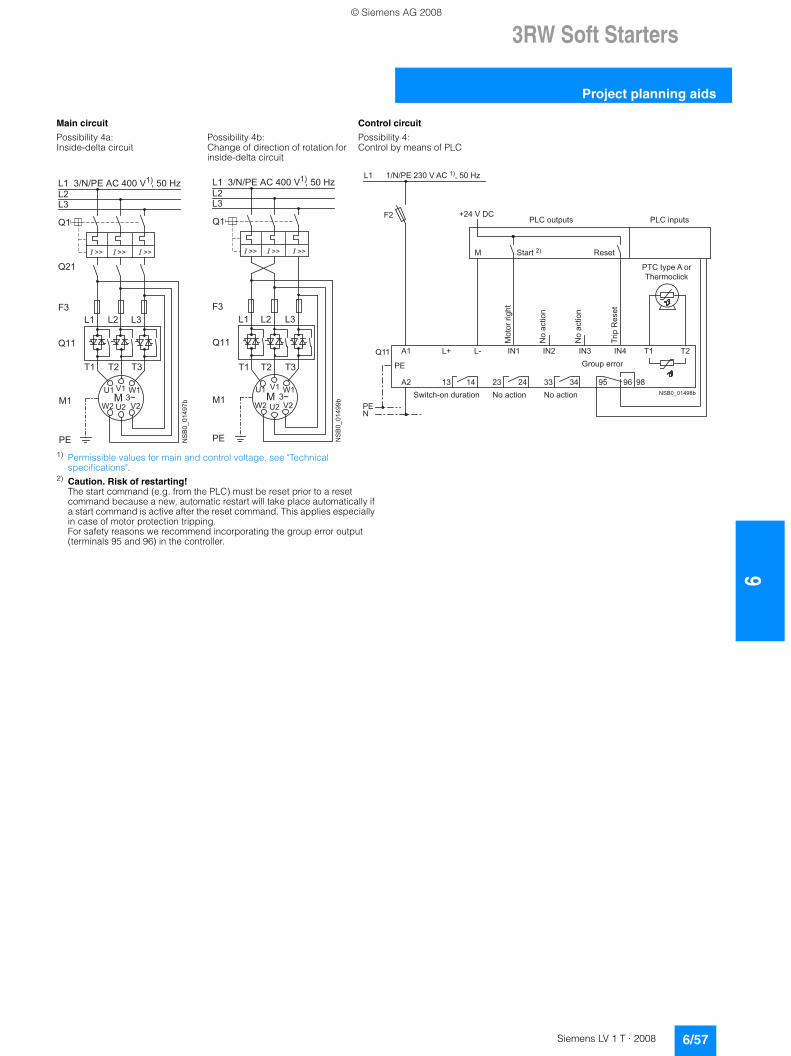
3RW Soft Starters
6/57Siemens LV 1 T · 2008
6
Project planning aids
1) Permissible values for main and control voltage, see "Technical specifications".
2) Caution. Risk of restarting!The start command (e.g. from the PLC) must be reset prior to a reset command because a new, automatic restart will take place automatically if a start command is active after the reset command. This applies especially in case of motor protection tripping.For safety reasons we recommend incorporating the group error output (terminals 95 and 96) in the controller.
Main circuit Control circuit
Possibility 4a: Possibility 4b: Possibility 4:Inside-delta circuit Change of direction of rotation for
inside-delta circuitControl by means of PLC
-2 � 1 �
0 (
0 �
1 ( 2 (
* � �
- �
� ���������
# � # ( #
/ � / ( /
* �
"
* ( �
5 6
.
#
# (
� �# � , , ! � ! 5 6 , ' 7 , � � � , 2 , , � , � � , 8 9
# � # ( #
/ � / ( /
- �
� ���������-
2 �0 � 1 �
0 (1 ( 2 (
5 6
.
* �
#
# (
� �
* � �
"
# � , , ! � ! 5 6 , ' 7 , � � � , 2 , , � , � � , 8 9
NSB0_01498b
+
L1 1/N/PE 230 V AC 1), 50 Hz
PTC type A orThermoclick
No action
Group error
Mot
or ri
ght
No
actio
n
No
actio
n
No actionSwitch-on duration
PLC outputs PLC inputs
Trip
Res
et
Reset Start 2)
Q11
PE
IN1 T1 T2
F2
N
L+ L-A1 IN2 IN3 IN4
A2 13 14 23 24 33 34 95 9896
PE
+24 V DC
M
© Siemens AG 2008
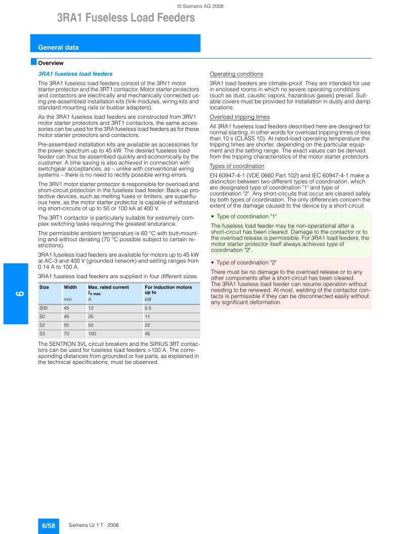
63RA1 Fuseless Load Feeders
General data
6/58 Siemens LV 1 T · 2008
■ Overview
3RA1 fuseless load feeders
The 3RA1 fuseless load feeders consist of the 3RV1 motor starter protector and the 3RT1 contactor. Motor starter protectors and contactors are electrically and mechanically connected us-ing pre-assembled installation kits (link modules, wiring kits and standard mounting rails or busbar adapters).
As the 3RA1 fuseless load feeders are constructed from 3RV1 motor starter protectors and 3RT1 contactors, the same acces-sories can be used for the 3RA fuseless load feeders as for these motor starter protectors and contactors.
Pre-assembled installation kits are available as accessories for the power spectrum up to 45 kW. The desired fuseless load feeder can thus be assembled quickly and economically by the customer. A time saving is also achieved in connection with switchgear acceptances, as – unlike with conventional wiring systems – there is no need to rectify possible wiring errors.
The 3RV1 motor starter protector is responsible for overload and short-circuit protection in the fuseless load feeder. Back-up pro-tective devices, such as melting fuses or limiters, are superflu-ous here, as the motor starter protector is capable of withstand-ing short-circuits of up to 50 or 100 kA at 400 V.
The 3RT1 contactor is particularly suitable for extremely com-plex switching tasks requiring the greatest endurance.
The permissible ambient temperature is 60 °C with butt-mount-ing and without derating (70 °C possible subject to certain re-strictions).
3RA1 fuseless load feeders are available for motors up to 45 kW at AC-3 and 400 V (grounded network) and setting ranges from 0.14 A to 100 A.
3RA1 fuseless load feeders are supplied in four different sizes:
The SENTRON 3VL circuit breakers and the SIRIUS 3RT contac-tors can be used for fuseless load feeders >100 A. The corre-sponding distances from grounded or live parts, as explained in the technical specifications, must be observed.
Operating conditions
3RA1 load feeders are climate-proof. They are intended for use in enclosed rooms in which no severe operating conditions (such as dust, caustic vapors, hazardous gases) prevail. Suit-able covers must be provided for installation in dusty and damp locations.
Overload tripping times
All 3RA1 fuseless load feeders described here are designed for normal starting, in other words for overload tripping times of less than 10 s (CLASS 10). At rated-load operating temperature the tripping times are shorter, depending on the particular equip-ment and the setting range. The exact values can be derived from the tripping characteristics of the motor starter protectors.
Types of coordination
EN 60947-4-1 (VDE 0660 Part 102) and IEC 60947-4-1 make a distinction between two different types of coordination, which are designated type of coordination "1" and type of coordination "2". Any short-circuits that occur are cleared safely by both types of coordination. The only differences concern the extent of the damage caused to the device by a short-circuit.
Size Width
mm
Max. rated current In max
A
For induction motors up to
kW
S00 45 12 5.5
S0 45 25 11
S2 55 50 22
S3 70 100 45
• Type of coordination "1"
The fuseless load feeder may be non-operational after a short-circuit has been cleared. Damage to the contactor or to the overload release is permissible. For 3RA1 load feeders, the motor starter protector itself always achieves type of coordination "2".
• Type of coordination "2"
There must be no damage to the overload release or to any other components after a short-circuit has been cleared. The 3RA1 fuseless load feeder can resume operation without needing to be renewed. At most, welding of the contactor con-tacts is permissible if they can be disconnected easily without any significant deformation.
© Siemens AG 2008
3RA1 Fuseless Load Feeders
6/59Siemens LV 1 T · 2008
6
General data
■ Design
Complete units
The 3RA1 fuseless load feeders can be ordered as complete units for direct start or for reversing duty. Control supply voltages of 50 Hz 230 V AC or 24 V DC and assembly on a 35 mm standard mounting rail or in a 40 or 60 mm busbar system are possible.Single devices for customer assembly can be ordered if other rated control supply voltages are required. The installation kits simplify customer assembly of the load feeders.The corresponding distances from grounded or live parts, as detailed in the technical specifications, must be observed.
Customer assembly
The standard devices can be combined optimally – in terms of both technical specifications and dimensions, thanks to the modular system of the SIRIUS series.
The fuseless load feeders can thus be assembled easily by the customer. It is simply necessary to assemble the standard 3RV1 motor starter protector and 3RT1 contactor and the appropriate installation kit together.
For the order numbers for single devices and installation kits, see the selection and ordering data "3RA11 Direct-On-Line Starters and 3RA12 Reversing Starters for Standard Mounting Rail, Screw Mounting or Busbar Systems".
For installation kits for direct start or reversing duty for mounting on standard mounting rails or busbars, see ordering data "Accessories for Direct-On-Line Starters and Reversing Starters".
If a motor starter protector with a rotary operating mechanism is required for the lower setting ranges up to 12 A, the S0 motor starter protector can also be assembled with an S00 contactor. A special link module is available for this purpose.
For the installation of feeders, it is imperative to use standard mounting rail adapters, as from size S2 for direct start and as from size S0 for reversing duty, to ensure the necessary mechan-ical strength. A standard mounting rail adapter is not necessary if a busbar adapter is used.
Accessories
The accessories for the single devices, such as auxiliary switches and undervoltage trip units, can also be used for the 3RA1 fuseless load feeders.
In addition, certain accessories have been optimized for the fuseless load feeders. They include the top-connected, trans-verse auxiliary switch on the motor starter protector with one changeover contact or one NO contact + one NC contact. Special auxiliary contact blocks that can be snapped on from below are available for the contactor. These two accessories en-able the fuseless load feeders to be wired simply without having to route cables through the device.
The special accessories for 3RA fuseless load feeders take the form of installation kits for 3RV1 motor starter protectors and 3RT1 contactors.
Mounting
3RA1 fuseless load feeders are available for assembly on TH 35 standard mounting rails according to EN 60715 (depth 15 mm) or on busbar adapters with a busbar center-to-center clearance of 40 or 60 mm and a busbar thickness of 5 or 10 mm with cham-fered edges.
The fuseless load feeders are also suitable for screw mounting.
Up to size S0 the 3RA11 fuseless load feeders can also be con-figured with the 3RV19 infeed system (see 3RV19 Infeed Sys-tem).
Size S00 and S0 can be screwed on with the aid of push-in lugs (see "Accessories for Direct-On-Line and Reversing Starters").
© Siemens AG 2008
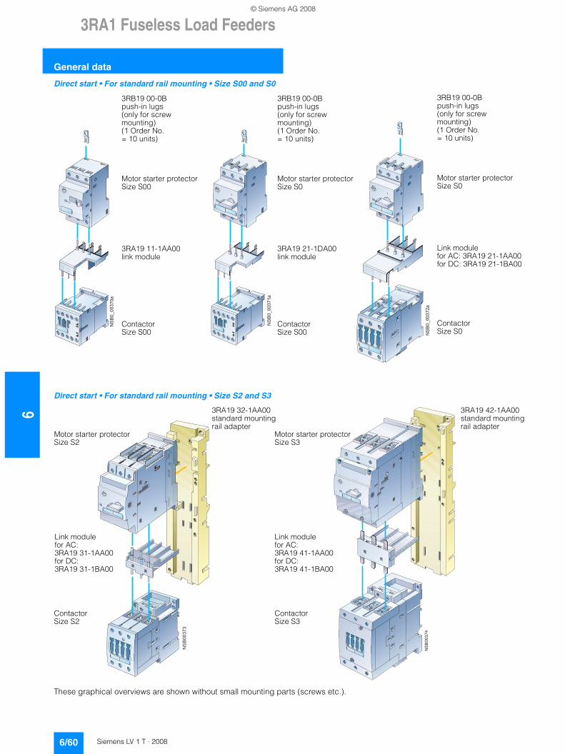
63RA1 Fuseless Load Feeders
General data
6/60 Siemens LV 1 T · 2008
Direct start • For standard rail mounting • Size S00 and S0
Direct start • For standard rail mounting • Size S2 and S3
These graphical overviews are shown without small mounting parts (screws etc.).
����
����
��
3RB19 00-0Bpush-in lugs(only for screw mounting)(1 Order No.= 10 units)
Motor starter protectorSize S00
3RA19 11-1AA00link module
ContactorSize S00
����
����
�
3RB19 00-0Bpush-in lugs(only for screw mounting)(1 Order No.= 10 units)
Motor starter protectorSize S0
3RA19 21-1DA00link module
ContactorSize S00
����
����
��
3RB19 00-0Bpush-in lugs(only for screw mounting)(1 Order No.= 10 units)
Motor starter protectorSize S0
Link modulefor AC: 3RA19 21-1AA00for DC: 3RA19 21-1BA00
ContactorSize S0
����
���
3RA19 32-1AA00 standard mounting rail adapter
Motor starter protectorSize S2
Link modulefor AC:3RA19 31-1AA00for DC:3RA19 31-1BA00
ContactorSize S2
����
��
3RA19 42-1AA00 standard mounting rail adapter
Motor starter protectorSize S3
Link module for AC:3RA19 41-1AA00for DC:3RA19 41-1BA00
ContactorSize S3
© Siemens AG 2008
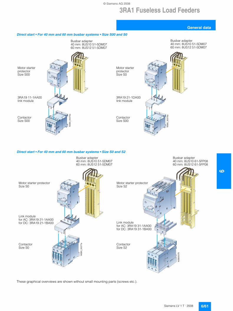
3RA1 Fuseless Load Feeders
6/61Siemens LV 1 T · 2008
6
General data
Direct start • For 40 mm and 60 mm busbar systems • Size S00 and S0
Direct start • For 40 mm and 60 mm busbar systems • Size S0 and S2
These graphical overviews are shown without small mounting parts (screws etc.).
����
����
��
Busbar adapter40 mm: 8US10 51-5DM0760 mm: 8US12 51-5DM07
Motor starter protectorSize S00
3RA19 11-1AA00 link module
ContactorSize S00
����
����
��
Busbar adapter40 mm: 8US10 51-5DM0760 mm: 8US12 51-5DM07
Motor starter protectorSize S0
3RA19 21-1DA00 link module
ContactorSize S00
����
����
��
Busbar adapter40 mm: 8US10 51-5DM0760 mm: 8US12 51-5DM07
Motor starter protectorSize S0
Link modulefor AC: 3RA19 21-1AA00for DC: 3RA19 21-1BA00
ContactorSize S0
����
���
Busbar adapter40 mm: 8US10 61-5FP0860 mm: 8US12 61-5FP08
Motor starter protectorSize S2
Link modulefor AC: 3RA19 31-1AA00for DC: 3RA19 31-1BA00
ContactorSize S2
© Siemens AG 2008
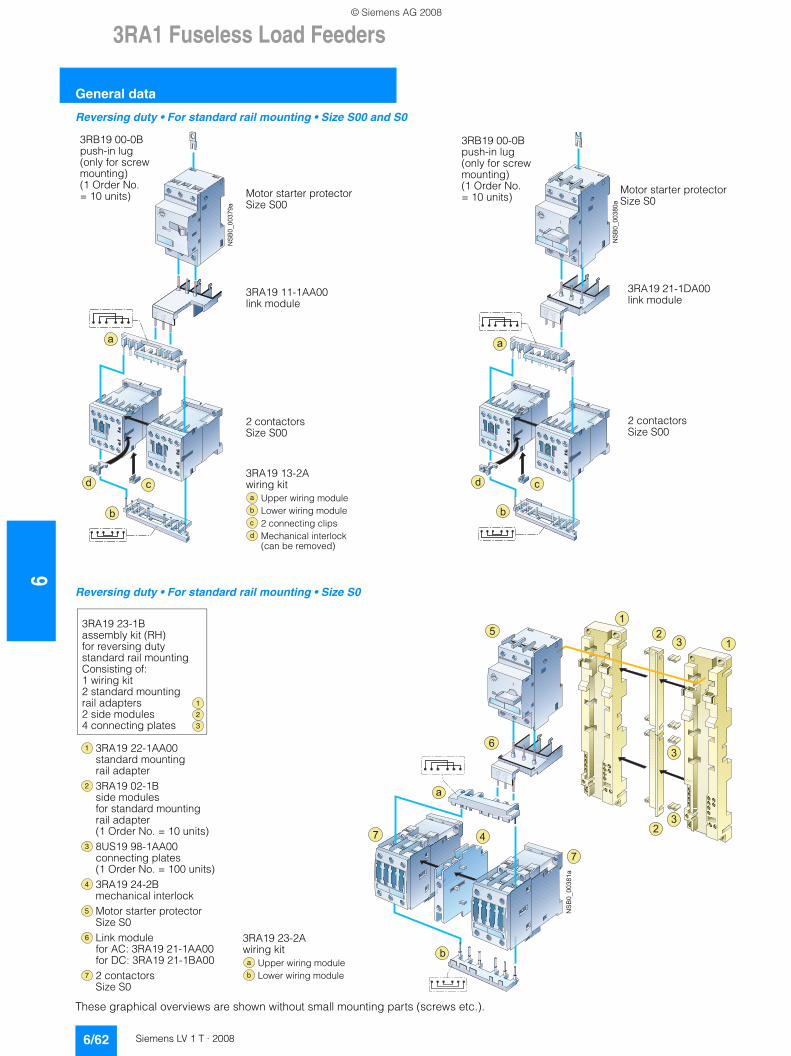
63RA1 Fuseless Load Feeders
General data
6/62 Siemens LV 1 T · 2008
Reversing duty • For standard rail mounting • Size S00 and S0
Reversing duty • For standard rail mounting • Size S0
These graphical overviews are shown without small mounting parts (screws etc.).
����
����
��
�
�
!
3RB19 00-0B push-in lug(only for screw mounting)(1 Order No.= 10 units) Motor starter protector
Size S00
3RA19 11-1AA00link module
2 contactorsSize S00
3RA19 13-2Awiring kit
Upper wiring moduleLower wiring module2 connecting clipsMechanical interlock (can be removed)
�
�
�
�
����
����
��
!
�
�
3RB19 00-0B push-in lug(only for screw mounting)(1 Order No.= 10 units)
Motor starter protectorSize S0
3RA19 21-1DA00 link module
2 contactorsSize S00
����
����
�
�
�
�
� �
�
�
�
�
�
�
3RA19 23-2Awiring kit
Upper wiring moduleLower wiring module
�
�
3RA19 23-1Bassembly kit (RH) for reversing duty standard rail mountingConsisting of:1 wiring kit2 standard mounting rail adapters2 side modules 4 connecting plates
�
�
�
3RA19 22-1AA00standard mounting rail adapter3RA19 02-1Bside modulesfor standard mounting rail adapter(1 Order No. = 10 units)8US19 98-1AA00connecting plates(1 Order No. = 100 units)3RA19 24-2Bmechanical interlockMotor starter protectorSize S0Link modulefor AC: 3RA19 21-1AA00 for DC: 3RA19 21-1BA002 contactorsSize S0
�
�
�
�
�
© Siemens AG 2008
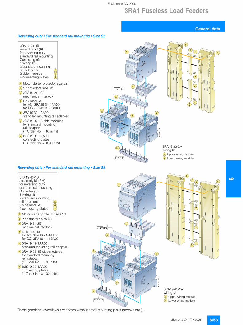
3RA1 Fuseless Load Feeders
6/63Siemens LV 1 T · 2008
6
General data
Reversing duty • For standard rail mounting • Size S2
Reversing duty • For standard rail mounting • Size S3
These graphical overviews are shown without small mounting parts (screws etc.).
3RA19 33-1Bassembly kit (RH)for reversing dutystandard rail mountingConsisting of:1 wiring kit2 standard mounting rail adapters2 side modules 4 connecting plates
�
Motor starter protector size S22 contactors size S23RA19 24-2Bmechanical interlockLink modulefor AC: 3RA19 31-1AA00for DC: 3RA19 31-1BA003RA19 32-1AA00standard mounting rail adapter3RA19 02-1B side modulesfor standard mounting rail adapter(1 Order No. = 10 units)8US19 98-1AA00connecting plates(1 Order No. = 100 units)
�
�
�
�
� ����
���
�
�
�
��
�
��
�
�
��
�
3RA19 33-2Awiring kit
Upper wiring moduleLower wiring module
�
�
3RA19 43-1Bassembly kit (RH)for reversing dutystandard rail mountingConsisting of:1 wiring kit2 standard mounting rail adapters2 side modules 4 connecting plates
�
Motor starter protector size S32 contactors size S33RA19 24-2Bmechanical interlockLink modulefor AC: 3RA19 41-1AA00for DC: 3RA19 41-1BA003RA19 42-1AA00standard mounting rail adapter3RA19 02-1B side modulesfor standard mounting rail adapter(1 Order No. = 10 units)8US19 98-1AA00connecting plates(1 Order No. = 100 units)
�
�
�
�
�
����
���
�
��
�
�
�
��
�
�
�
�
�
3RA19 43-2Awiring kit
Upper wiring moduleLower wiring module
�
�
© Siemens AG 2008
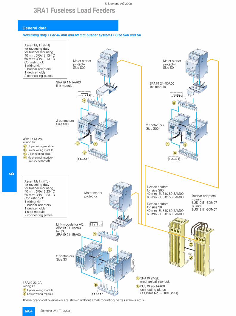
63RA1 Fuseless Load Feeders
General data
6/64 Siemens LV 1 T · 2008
Reversing duty • For 40 mm and 60 mm busbar systems • Size S00 and S0
These graphical overviews are shown without small mounting parts (screws etc.).
����
����
��
!
�
�
�
�
�
�
!
�
�
Assembly kit (RH)for reversing dutyfor busbar mounting40 mm: 3RA19 13-1C60 mm: 3RA19 13-1DConsisting of:1 wiring kit2 busbar adapters1 device holder2 connecting plates
Motor starter protectorSize S00
3RA19 11-1AA00link module
2 contactorsSize S00
Motor starter protectorSize S0
3RA19 21-1DA00link module
2 contactorsSize S00
Motor starter protector
Assembly kit (RS)for reversing dutyfor busbar mounting40 mm: 3RA19 23-1C60 mm: 3RA19 23-1DConsisting of:1 wiring kit2 busbar adapters1 device holder1 side module2 connecting plates
Link module for AC:3RA19 21-1AA00for DC:3RA19 21-1BA00
2 contactorsSize S0
3RA19 13-2Awiring kit
Upper wiring moduleLower wiring module2 connecting clipsMechanical interlock (can be removed)
�
�
�
�
3RA19 23-2Awiring kit
Upper wiring moduleLower wiring module
�
�
3RA19 24-2Bmechanical interlock8US19 98-1AA00connecting plates(1 Order No. = 100 units)
�
�
Device holdersfor size S0040 mm: 8US10 50-5AM0060 mm: 8US12 50-5AM00
Device holdersfor size S040 mm: 8US10 60-5AM0060 mm: 8US12 60-5AM00
Busbar adapters40 mm:8US10 51-5DM0760 mm:8US12 51-5DM07
© Siemens AG 2008
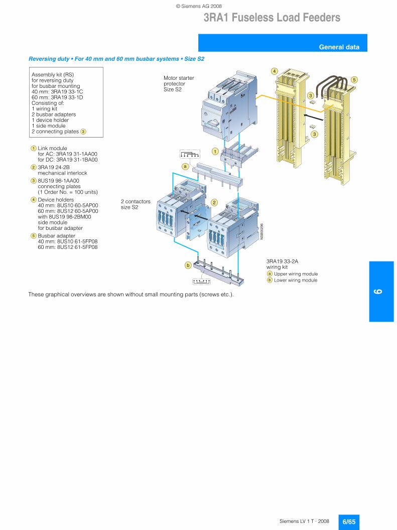
3RA1 Fuseless Load Feeders
6/65Siemens LV 1 T · 2008
6
General data
Reversing duty • For 40 mm and 60 mm busbar systems • Size S2
These graphical overviews are shown without small mounting parts (screws etc.).
� ���
��
�
�
�
�
�
�
�
3RA19 33-2Awiring kit
Upper wiring moduleLower wiring module
�
�
Link modulefor AC: 3RA19 31-1AA00for DC: 3RA19 31-1BA003RA19 24-2Bmechanical interlock8US19 98-1AA00connecting plates(1 Order No. = 100 units)Device holders40 mm: 8US10 60-5AP0060 mm: 8US12 60-5AP00with 8US19 98-2BM00side modulefor busbar adapterBusbar adapter40 mm: 8US10 61-5FP0860 mm: 8US12 61-5FP08
�
�
�
�
2 contactorssize S2
Motor starter protectorSize S2
Assembly kit (RS)for reversing dutyfor busbar mounting40 mm: 3RA19 33-1C60 mm: 3RA19 33-1DConsisting of:1 wiring kit2 busbar adapters1 device holder1 side module2 connecting plates �
© Siemens AG 2008
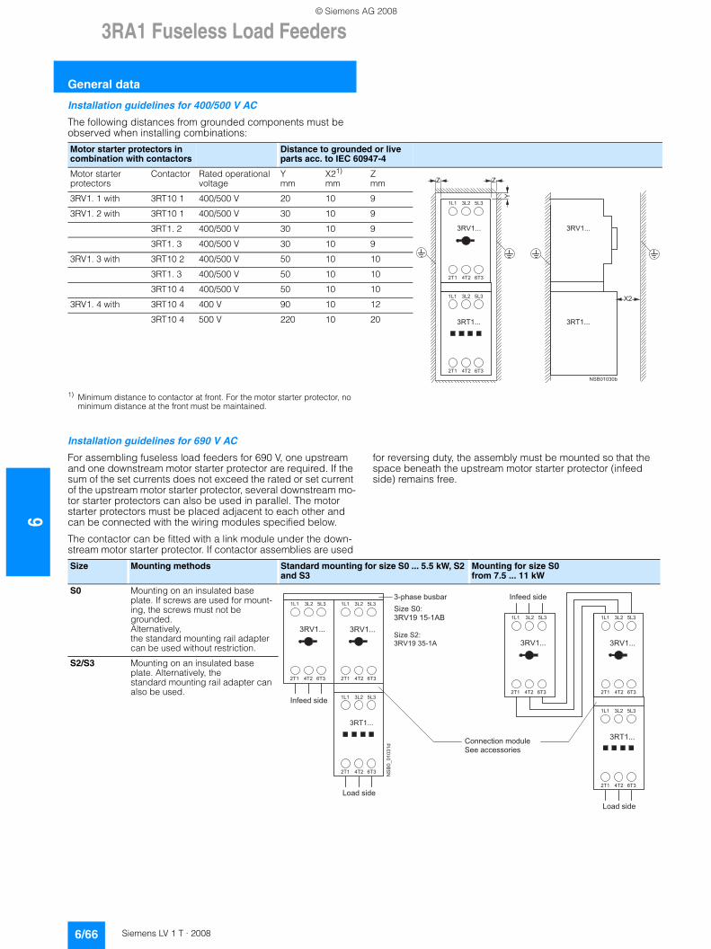
63RA1 Fuseless Load Feeders
General data
6/66 Siemens LV 1 T · 2008
Installation guidelines for 400/500 V AC
The following distances from grounded components must be observed when installing combinations:
1) Minimum distance to contactor at front. For the motor starter protector, no minimum distance at the front must be maintained.
Installation guidelines for 690 V AC
For assembling fuseless load feeders for 690 V, one upstream and one downstream motor starter protector are required. If the sum of the set currents does not exceed the rated or set current of the upstream motor starter protector, several downstream mo-tor starter protectors can also be used in parallel. The motor starter protectors must be placed adjacent to each other and can be connected with the wiring modules specified below.
The contactor can be fitted with a link module under the down-stream motor starter protector. If contactor assemblies are used
for reversing duty, the assembly must be mounted so that the space beneath the upstream motor starter protector (infeed side) remains free.
Motor starter protectors in combination with contactors
Distance to grounded or live parts acc. to IEC 60947-4
Motor starter protectors
Contactor Rated operational voltage
Ymm
X21)
mmZmm
3RV1. 1 with 3RT10 1 400/500 V 20 10 9
3RV1. 2 with 3RT10 1 400/500 V 30 10 9
3RT1. 2 400/500 V 30 10 9
3RT1. 3 400/500 V 30 10 9
3RV1. 3 with 3RT10 2 400/500 V 50 10 10
3RT1. 3 400/500 V 50 10 10
3RT10 4 400/500 V 50 10 10
3RV1. 4 with 3RT10 4 400 V 90 10 12
3RT10 4 500 V 220 10 20
�������
�������
��� ��� ��
��� �� ���
��� ��� ��
��� �� ���
� �������
�������
�������
�
�
�
��
Size Mounting methods Standard mounting for size S0 ... 5.5 kW, S2 and S3
Mounting for size S0 from 7.5 ... 11 kW
S0 Mounting on an insulated base plate. If screws are used for mount-ing, the screws must not be grounded. Alternatively, the standard mounting rail adapter can be used without restriction.
S2/S3 Mounting on an insulated base plate. Alternatively, the standard mounting rail adapter can also be used.
�����������
� � � � �� � � � �
� � � � � �
� � � � � � � � � � � �
� � � � � � � � �� � � � � � � � �
� � � � � �
� � � � � � � � �
� � � � �� � � � �
� � � � � �
� � � � � � � � � � � �
� � � � � � � � �� � � � � � � � �
� � � � � �
� � � � � � � � �
� � � � � � � � � � � � � �
� � � � � � � �
� � � � � � � � �
� � � � � � � �
� � � � � � � �
! " # # � $ % � " # � & " � � ' �
� � � � � $ $ � � � " � � � �
( # ) � � � � � � � �
" � � � � � � �
( # ) � � � � � � � �
" � � � � � � �
© Siemens AG 2008
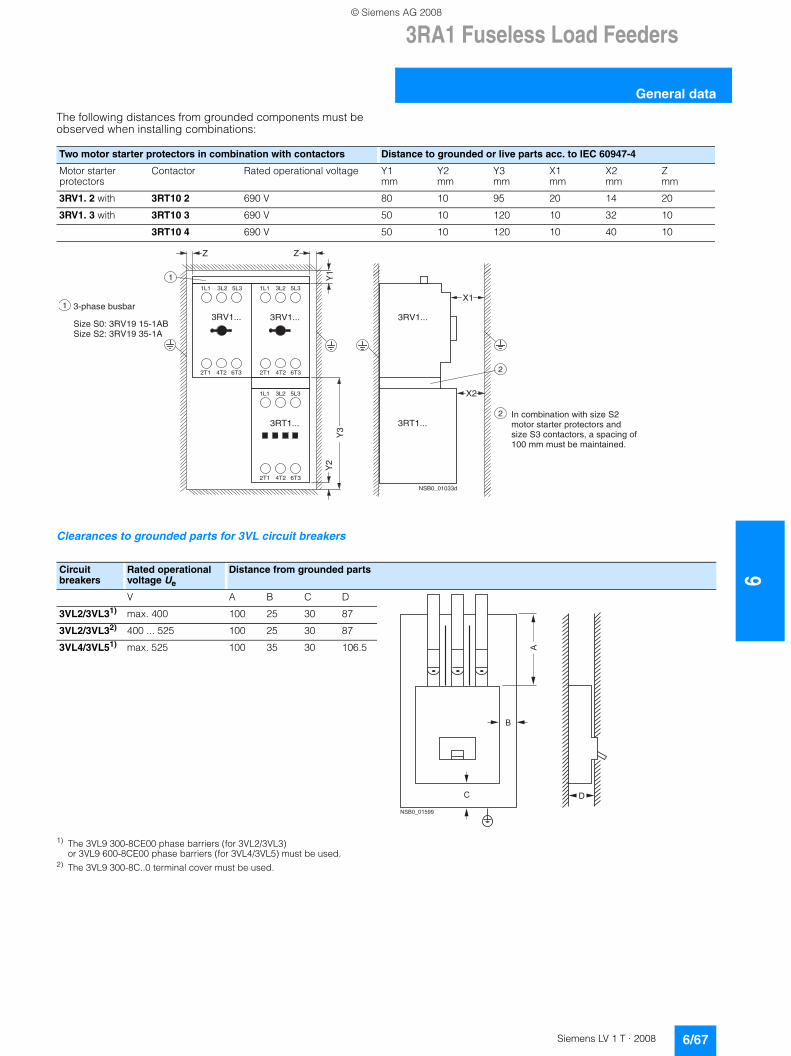
3RA1 Fuseless Load Feeders
6/67Siemens LV 1 T · 2008
6
General data
The following distances from grounded components must be observed when installing combinations:
Clearances to grounded parts for 3VL circuit breakers
1) The 3VL9 300-8CE00 phase barriers (for 3VL2/3VL3) or 3VL9 600-8CE00 phase barriers (for 3VL4/3VL5) must be used.
2) The 3VL9 300-8C..0 terminal cover must be used.
Two motor starter protectors in combination with contactors Distance to grounded or live parts acc. to IEC 60947-4
Motor starter protectors
Contactor Rated operational voltage Y1mm
Y2mm
Y3mm
X1mm
X2mm
Zmm
3RV1. 2 with 3RT10 2 690 V 80 10 95 20 14 20
3RV1. 3 with 3RT10 3 690 V 50 10 120 10 32 10
3RT10 4 690 V 50 10 120 10 40 10
3RV1...3RV1...
3RT1...
1L1 3L2 5L3 1L1 3L2 5L3
2T1 4T2 6T32T1 4T2 6T3
1L1 3L2 5L3
2T1 4T2 6T3
NSB0_01033d
3RV1...
3RT1...
Z
Y1
Z
Y2
Y3
X2
X1
1
2
1
2
3-phase busbar
Size S0: 3RV19 15-1ABSize S2: 3RV19 35-1A
In combination with size S2motor starter protectors and size S3 contactors, a spacing of 100 mm must be maintained.
Circuit breakers
Rated operational voltage Ue
Distance from grounded parts
V A B C D
3VL2/3VL31) max. 400 100 25 30 87
3VL2/3VL32) 400 ... 525 100 25 30 87
3VL4/3VL51) max. 525 100 35 30 106.5
�
" �
��������
�
© Siemens AG 2008
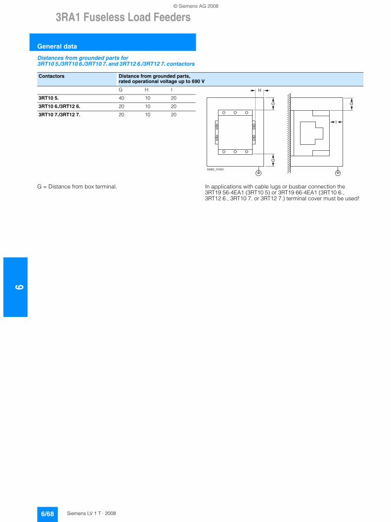
63RA1 Fuseless Load Feeders
General data
6/68 Siemens LV 1 T · 2008
Distances from grounded parts for 3RT10 5./3RT10 6./3RT10 7. and 3RT12 6./3RT12 7. contactors
G = Distance from box terminal. In applications with cable lugs or busbar connection the 3RT19 56-4EA1 (3RT10 5) or 3RT19 66-4EA1 (3RT10 6., 3RT12 6., 3RT10 7. or 3RT12 7.) terminal cover must be used!
Contactors Distance from grounded parts,rated operational voltage up to 690 V
G H I
3RT10 5. 40 10 20
3RT10 6./3RT12 6. 20 10 20
3RT10 7./3RT12 7. 20 10 20
��������
#
$
%%
%
© Siemens AG 2008
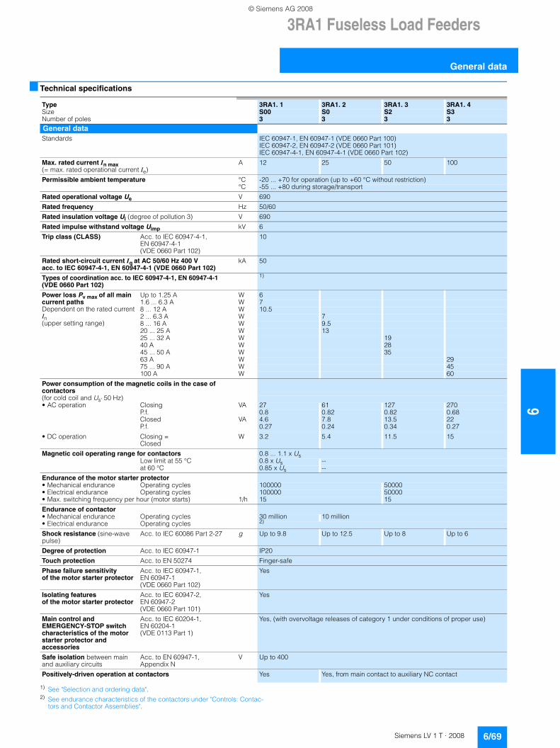
3RA1 Fuseless Load Feeders
6/69Siemens LV 1 T · 2008
6
General data
■ Technical specifications
1) See "Selection and ordering data".2) See endurance characteristics of the contactors under "Controls: Contac-
tors and Contactor Assemblies".
Type 3RA1. 1 3RA1. 2 3RA1. 3 3RA1. 4Size S00 S0 S2 S3Number of poles 3 3 3 3General dataStandards IEC 60947-1, EN 60947-1 (VDE 0660 Part 100)
IEC 60947-2, EN 60947-2 (VDE 0660 Part 101) IEC 60947-4-1, EN 60947-4-1 (VDE 0660 Part 102)
Max. rated current In max (= max. rated operational current Ie)
A 12 25 50 100
Permissible ambient temperature °C -20 ... +70 for operation (up to +60 °C without restriction)°C -55 ... +80 during storage/transport
Rated operational voltage Ue V 690
Rated frequency Hz 50/60
Rated insulation voltage Ui (degree of pollution 3) V 690
Rated impulse withstand voltage Uimp kV 6
Trip class (CLASS) Acc. to IEC 60947-4-1, EN 60947-4-1 (VDE 0660 Part 102)
10
Rated short-circuit current Iq at AC 50/60 Hz 400 V acc. to IEC 60947-4-1, EN 60947-4-1 (VDE 0660 Part 102)
kA 50
Types of coordination acc. to IEC 60947-4-1, EN 60947-4-1(VDE 0660 Part 102)
1)
Power loss Pv max of all main current paths Dependent on the rated current In(upper setting range)
Up to 1.25 A W 61.6 ... 6.3 A W 78 ... 12 A W 10.52 ... 6.3 A W 78 ... 16 A W 9.520 ... 25 A W 1325 ... 32 A W 1940 A W 2845 ... 50 A W 3563 A W 2975 ... 90 A W 45100 A W 60
Power consumption of the magnetic coils in the case of contactors(for cold coil and Us' 50 Hz)• AC operation Closing VA 27 61 127 270
P.f. 0.8 0.82 0.82 0.68Closed VA 4.6 7.8 13.5 22P.f. 0.27 0.24 0.34 0.27
• DC operation Closing = Closed
W 3.2 5.4 11.5 15
Magnetic coil operating range for contactors 0.8 ... 1.1 x UsLow limit at 55 °C 0.8 x Us --at 60 °C 0.85 x Us --
Endurance of the motor starter protector• Mechanical endurance Operating cycles 100000 50000• Electrical endurance Operating cycles 100000 50000• Max. switching frequency per hour (motor starts) 1/h 15 15
Endurance of contactor• Mechanical endurance Operating cycles 30 million 10 million• Electrical endurance Operating cycles 2)
Shock resistance (sine-wave pulse)
Acc. to IEC 60086 Part 2-27 g Up to 9.8 Up to 12.5 Up to 8 Up to 6
Degree of protection Acc. to IEC 60947-1 IP20
Touch protection Acc. to EN 50274 Finger-safe
Phase failure sensitivity of the motor starter protector
Acc. to IEC 60947-1, EN 60947-1 (VDE 0660 Part 102)
Yes
Isolating features of the motor starter protector
Acc. to IEC 60947-2, EN 60947-2 (VDE 0660 Part 101)
Yes
Main control and EMERGENCY-STOP switch characteristics of the motor starter protector and accessories
Acc. to IEC 60204-1, EN 60204-1 (VDE 0113 Part 1)
Yes, (with overvoltage releases of category 1 under conditions of proper use)
Safe isolation between main and auxiliary circuits
Acc. to EN 60947-1, Appendix N
V Up to 400
Positively-driven operation at contactors Yes Yes, from main contact to auxiliary NC contact
© Siemens AG 2008
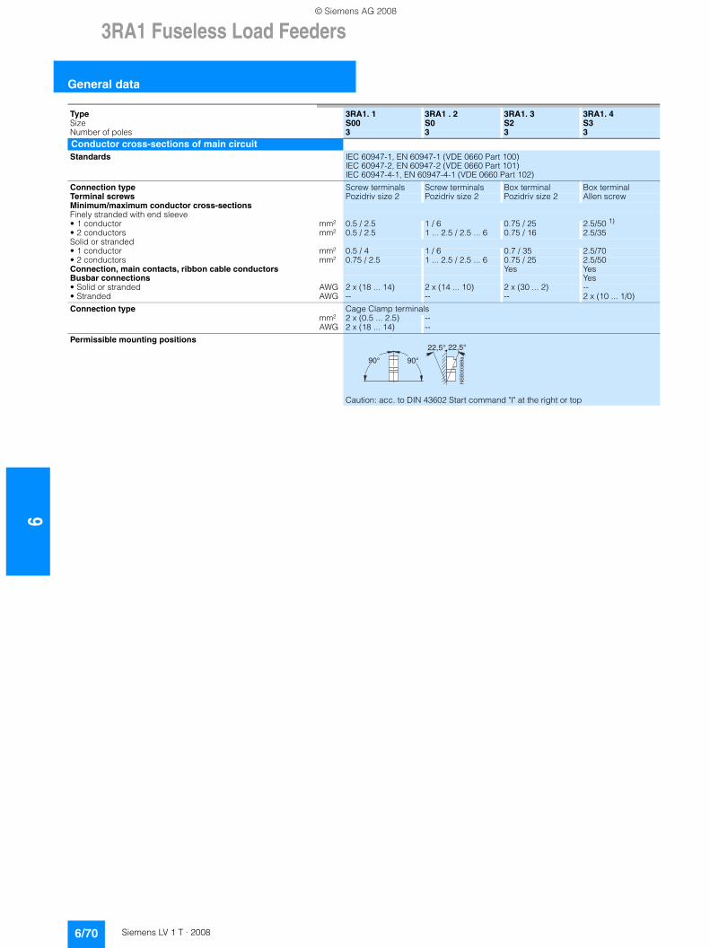
63RA1 Fuseless Load Feeders
General data
6/70 Siemens LV 1 T · 2008
Type 3RA1. 1 3RA1 . 2 3RA1. 3 3RA1. 4Size S00 S0 S2 S3Number of poles 3 3 3 3Conductor cross-sections of main circuitStandards IEC 60947-1, EN 60947-1 (VDE 0660 Part 100)
IEC 60947-2, EN 60947-2 (VDE 0660 Part 101) IEC 60947-4-1, EN 60947-4-1 (VDE 0660 Part 102)
Connection type Screw terminals Screw terminals Box terminal Box terminalTerminal screws Pozidriv size 2 Pozidriv size 2 Pozidriv size 2 Allen screwMinimum/maximum conductor cross-sectionsFinely stranded with end sleeve• 1 conductor mm² 0.5 / 2.5 1 / 6 0.75 / 25 2.5/50 1)
• 2 conductors mm² 0.5 / 2.5 1 ... 2.5 / 2.5 ... 6 0.75 / 16 2.5/35Solid or stranded• 1 conductor mm² 0.5 / 4 1 / 6 0.7 / 35 2.5/70• 2 conductors mm² 0.75 / 2.5 1 ... 2.5 / 2.5 ... 6 0.75 / 25 2.5/50Connection, main contacts, ribbon cable conductors Yes YesBusbar connections Yes• Solid or stranded AWG 2 x (18 ... 14) 2 x (14 ... 10) 2 x (30 ... 2) --• Stranded AWG -- -- -- 2 x (10 ... 1/0)
Connection type Cage Clamp terminalsmm² 2 x (0.5 ... 2.5) --AWG 2 x (18 ... 14) --
Permissible mounting positions
Caution: acc. to DIN 43602 Start command "I" at the right or top
90° 90°
NS
B00
369a
22,5° 22,5°
© Siemens AG 2008
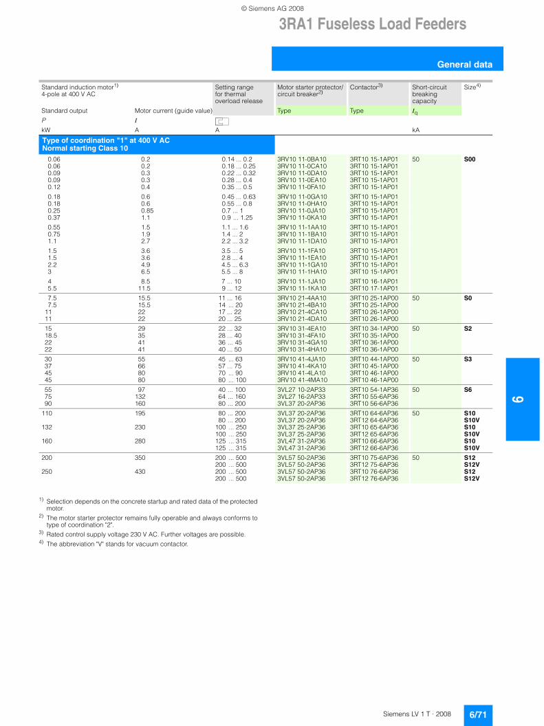
3RA1 Fuseless Load Feeders
6/71Siemens LV 1 T · 2008
6
General data
1) Selection depends on the concrete startup and rated data of the protected motor.
2) The motor starter protector remains fully operable and always conforms to type of coordination "2".
3) Rated control supply voltage 230 V AC. Further voltages are possible.4) The abbreviation "V" stands for vacuum contactor.
Standard induction motor1)
4-pole at 400 V ACSetting range for thermal overload release
Motor starter protector/circuit breaker2)
Contactor3) Short-circuit breaking capacity
Size4)
Standard output Motor current (guide value) Type Type IqP I
kW A A kA
Type of coordination "1" at 400 V ACNormal starting Class 10
0.06 0.2 0.14 ... 0.2 3RV10 11-0BA10 3RT10 15-1AP01 50 S000.06 0.2 0.18 ... 0.25 3RV10 11-0CA10 3RT10 15-1AP010.09 0.3 0.22 ... 0.32 3RV10 11-0DA10 3RT10 15-1AP010.09 0.3 0.28 ... 0.4 3RV10 11-0EA10 3RT10 15-1AP010.12 0.4 0.35 ... 0.5 3RV10 11-0FA10 3RT10 15-1AP01
0.18 0.6 0.45 ... 0.63 3RV10 11-0GA10 3RT10 15-1AP010.18 0.6 0.55 ... 0.8 3RV10 11-0HA10 3RT10 15-1AP010.25 0.85 0.7 ... 1 3RV10 11-0JA10 3RT10 15-1AP010.37 1.1 0.9 ... 1.25 3RV10 11-0KA10 3RT10 15-1AP01
0.55 1.5 1.1 ... 1.6 3RV10 11-1AA10 3RT10 15-1AP010.75 1.9 1.4 ... 2 3RV10 11-1BA10 3RT10 15-1AP011.1 2.7 2.2 ... 3.2 3RV10 11-1DA10 3RT10 15-1AP01
1.5 3.6 3.5 ... 5 3RV10 11-1FA10 3RT10 15-1AP011.5 3.6 2.8 ... 4 3RV10 11-1EA10 3RT10 15-1AP012.2 4.9 4.5 ... 6.3 3RV10 11-1GA10 3RT10 15-1AP013 6.5 5.5 ... 8 3RV10 11-1HA10 3RT10 15-1AP01
4 8.5 7 ... 10 3RV10 11-1JA10 3RT10 16-1AP015.5 11.5 9 ... 12 3RV10 11-1KA10 3RT10 17-1AP01
7.5 15.5 11 ... 16 3RV10 21-4AA10 3RT10 25-1AP00 50 S07.5 15.5 14 ... 20 3RV10 21-4BA10 3RT10 25-1AP00
11 22 17 ... 22 3RV10 21-4CA10 3RT10 26-1AP0011 22 20 ... 25 3RV10 21-4DA10 3RT10 26-1AP00
15 29 22 ... 32 3RV10 31-4EA10 3RT10 34-1AP00 50 S218.5 35 28 ... 40 3RV10 31-4FA10 3RT10 35-1AP0022 41 36 ... 45 3RV10 31-4GA10 3RT10 36-1AP0022 41 40 ... 50 3RV10 31-4HA10 3RT10 36-1AP00
30 55 45 ... 63 3RV10 41-4JA10 3RT10 44-1AP00 50 S337 66 57 ... 75 3RV10 41-4KA10 3RT10 45-1AP0045 80 70 ... 90 3RV10 41-4LA10 3RT10 46-1AP0045 80 80 ... 100 3RV10 41-4MA10 3RT10 46-1AP00
55 97 40 ... 100 3VL27 10-2AP33 3RT10 54-1AP36 50 S675 132 64 ... 160 3VL27 16-2AP33 3RT10 55-6AP3690 160 80 ... 200 3VL37 20-2AP36 3RT10 56-6AP36
110 195 80 ... 200 3VL37 20-2AP36 3RT10 64-6AP36 50 S1080 ... 200 3VL37 20-2AP36 3RT12 64-6AP36 S10V
132 230 100 ... 250 3VL37 25-2AP36 3RT10 65-6AP36 S10100 ... 250 3VL37 25-2AP36 3RT12 65-6AP36 S10V
160 280 125 ... 315 3VL47 31-2AP36 3RT10 66-6AP36 S10125 ... 315 3VL47 31-2AP36 3RT12 66-6AP36 S10V
200 350 200 ... 500 3VL57 50-2AP36 3RT10 75-6AP36 50 S12200 ... 500 3VL57 50-2AP36 3RT12 75-6AP36 S12V
250 430 200 ... 500 3VL57 50-2AP36 3RT10 76-6AP36 S12200 ... 500 3VL57 50-2AP36 3RT12 76-6AP36 S12V
© Siemens AG 2008
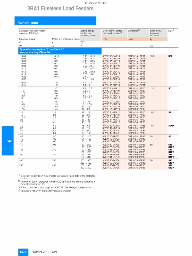
63RA1 Fuseless Load Feeders
General data
6/72 Siemens LV 1 T · 2008
1) Selection depends on the concrete startup and rated data of the protected motor.
2) The motor starter protector remains fully operable and always conforms to type of coordination "2".
3) Rated control supply voltage 230 V AC. Further voltages are possible.4) The abbreviation "V" stands for vacuum contactor.
Standard induction motor1)
4-pole at 400 V ACSetting range for thermal overload release
Motor starter protec-tor/circuit breaker2)
Contactor3) Short-circuit breaking capacity
Size4)
Standard output Motor current (guide value) Type Type IqP I
kW A A kA
Type of coordination "2" at 400 V ACNormal starting Class 10
0.04 0.16 0.11 ... 0.16 3RV10 11-0AA10 3RT10 15-1AP01 130 S000.06 0.2 0.14 ... 0.2 3RV10 11-0BA10 3RT10 15-1AP010.06 0.2 0.18 ... 0.25 3RV10 11-0CA10 3RT10 15-1AP010.09 0.3 0.22 ... 0.32 3RV10 11-0DA10 3RT10 15-1AP010.09 0.3 0.28 ... 0.4 3RV10 11-0EA10 3RT10 15-1AP010.12 0.4 0.35 ... 0.5 3RV10 11-0FA10 3RT10 15-1AP01
0.18 0.6 0.45 ... 0.63 3RV10 11-0GA10 3RT10 15-1AP010.18 0.6 0.55 ... 0.8 3RV10 11-0HA10 3RT10 15-1AP010.25 0.85 0.7 ... 1 3RV10 11-0JA10 3RT10 15-1AP010.37 1.1 0.9 ... 1.25 3RV10 11-0KA10 3RT10 15-1AP01
0.55 1.5 1.1 ... 1.6 3RV10 11-1AA10 3RT10 15-1AP010.75 1.9 1.4 ... 2 3RV10 11-1BA10 3RT10 15-1AP01
1.1 2.7 2.2 ... 3.2 3RV10 21-1DA10 3RT10 24-1AP00 130 S01.5 3.6 2.8 ... 4 3RV10 21-1EA10 3RT10 24-1AP001.5 3.6 3.5 ... 5 3RV10 21-1FA10 3RT10 24-1AP002.2 4.9 4.5 ... 6.3 3RV10 21-1GA10 3RT10 24-1AP003 6.5 5.5 ... 8 3RV10 21-1HA10 3RT10 24-1AP00
4 8.5 7 ... 10 3RV10 21-1JA10 3RT10 26-1AP005.5 11.5 9 ... 12.5 3RV10 21-1KA10 3RT10 26-1AP007.5 15.5 11 ... 16 3RV10 21-4AA10 3RT10 26-1AP007.5 15.5 14 ... 20 3RV10 21-4BA10 3RT10 26-1AP00
11 22 18 ... 25 3RV10 31-4DA10 3RT10 34-1AP00 100 S215 29 22 ... 32 3RV10 31-4EA10 3RT10 34-1AP0018.5 35 28 ... 40 3RV10 31-4FA10 3RT10 35-1AP0022 41 36 ... 45 3RV10 31-4GA10 3RT10 36-1AP0022 41 40 ... 50 3RV10 31-4HA10 3RT10 36-1AP00
30 55 45 ... 63 3RV10 42-4JA10 3RT10 54-1AP36 100 S3/S637 66 57 ... 75 3RV10 42-4KA10 3RT10 54-1AP3645 80 70 ... 90 3RV10 42-4LA10 3RT10 54-1AP3645 80 80 ... 100 3RV10 42-4MA10 3RT10 54-1AP36
55 97 40 ... 100 3VL27 10-2AP33 3RT10 54-1AP36 50 S675 132 64 ... 160 3VL27 16-2AP33 3RT10 55-6AP3690 160 80 ... 200 3VL37 20-2AP36 3RT10 56-6AP36
110 195 80 ... 200 3VL37 20-2AP36 3RT10 64-6AP36 50 S1080 ... 200 3VL37 20-2AP36 3RT12 64-6AP36 S10V
132 230 100 ... 250 3VL37 25-2AP36 3RT10 65-6AP36 S10100 ... 250 3VL37 25-2AP36 3RT12 65-6AP36 S10V
160 280 125 ... 315 3VL47 31-2AP36 3RT10 66-6AP36 S10125 ... 315 3VL47 31-2AP36 3RT12 66-6AP36 S10V
200 350 200 ... 500 3VL57 50-2AP36 3RT10 75-6AP36 50 S12200 ... 500 3VL57 50-2AP36 3RT12 75-6AP36 S12V
250 430 200 ... 500 3VL57 50-2AP36 3RT10 76-6AP36 S12200 ... 500 3VL57 50-2AP36 3RT12 76-6AP36 S12V
© Siemens AG 2008
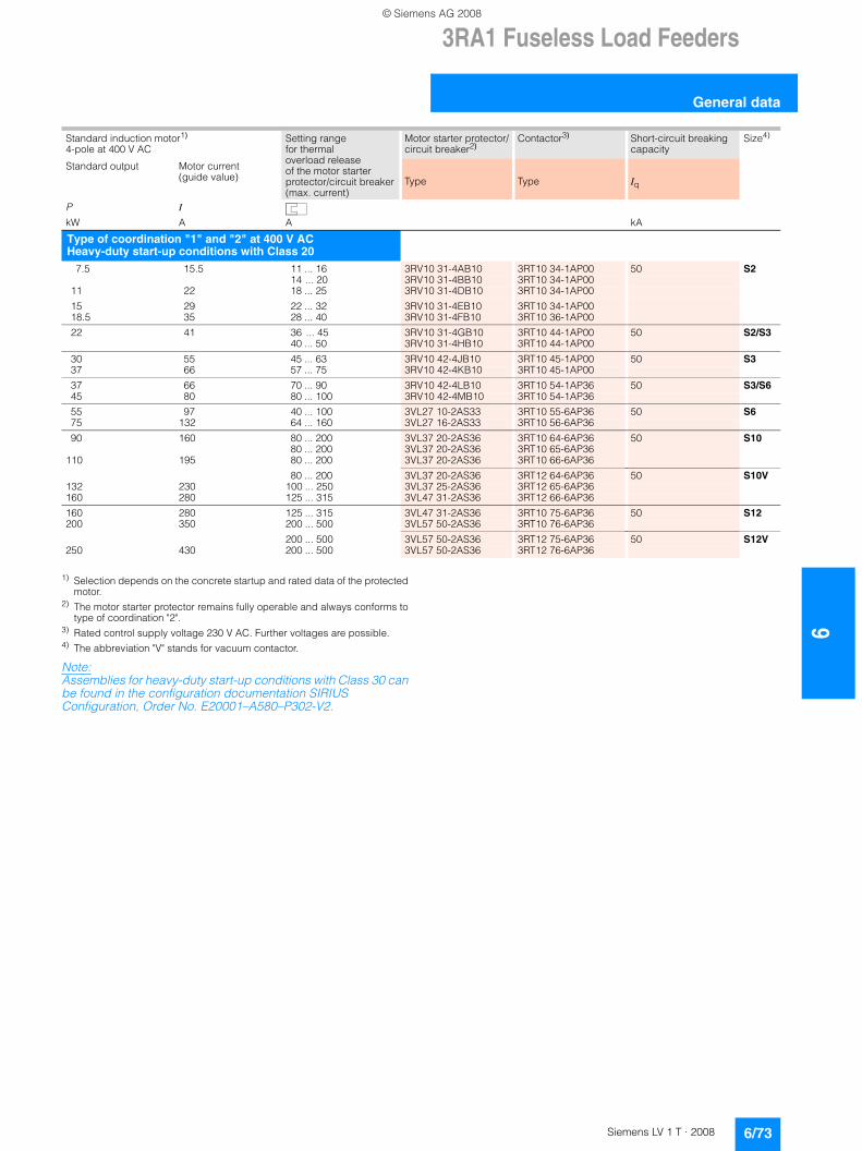
3RA1 Fuseless Load Feeders
6/73Siemens LV 1 T · 2008
6
General data
1) Selection depends on the concrete startup and rated data of the protected motor.
2) The motor starter protector remains fully operable and always conforms to type of coordination "2".
3) Rated control supply voltage 230 V AC. Further voltages are possible.4) The abbreviation "V" stands for vacuum contactor.
Note:Assemblies for heavy-duty start-up conditions with Class 30 can be found in the configuration documentation SIRIUS Configuration, Order No. E20001–A580–P302-V2.
Standard induction motor1)
4-pole at 400 V ACSetting range for thermal overload release of the motor starter protector/circuit breaker(max. current)
Motor starter protector/ circuit breaker2)
Contactor3) Short-circuit breaking capacity
Size4)
Standard output Motor current (guide value) Type Type Iq
P I
kW A A kA
Type of coordination "1" and "2" at 400 V AC Heavy-duty start-up conditions with Class 20
7.5 15.5 11 ... 16 3RV10 31-4AB10 3RT10 34-1AP00 50 S214 ... 20 3RV10 31-4BB10 3RT10 34-1AP00
11 22 18 ... 25 3RV10 31-4DB10 3RT10 34-1AP00
15 29 22 ... 32 3RV10 31-4EB10 3RT10 34-1AP0018.5 35 28 ... 40 3RV10 31-4FB10 3RT10 36-1AP00
22 41 36 ... 45 3RV10 31-4GB10 3RT10 44-1AP00 50 S2/S340 ... 50 3RV10 31-4HB10 3RT10 44-1AP00
30 55 45 ... 63 3RV10 42-4JB10 3RT10 45-1AP00 50 S337 66 57 ... 75 3RV10 42-4KB10 3RT10 45-1AP00
37 66 70 ... 90 3RV10 42-4LB10 3RT10 54-1AP36 50 S3/S645 80 80 ... 100 3RV10 42-4MB10 3RT10 54-1AP36
55 97 40 ... 100 3VL27 10-2AS33 3RT10 55-6AP36 50 S675 132 64 ... 160 3VL27 16-2AS33 3RT10 56-6AP36
90 160 80 ... 200 3VL37 20-2AS36 3RT10 64-6AP36 50 S1080 ... 200 3VL37 20-2AS36 3RT10 65-6AP36
110 195 80 ... 200 3VL37 20-2AS36 3RT10 66-6AP36
80 ... 200 3VL37 20-2AS36 3RT12 64-6AP36 50 S10V132 230 100 ... 250 3VL37 25-2AS36 3RT12 65-6AP36160 280 125 ... 315 3VL47 31-2AS36 3RT12 66-6AP36
160 280 125 ... 315 3VL47 31-2AS36 3RT10 75-6AP36 50 S12200 350 200 ... 500 3VL57 50-2AS36 3RT10 76-6AP36
200 ... 500 3VL57 50-2AS36 3RT12 75-6AP36 50 S12V250 430 200 ... 500 3VL57 50-2AS36 3RT12 76-6AP36
© Siemens AG 2008
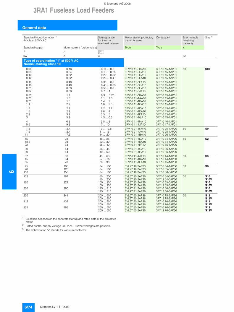
63RA1 Fuseless Load Feeders
General data
6/74 Siemens LV 1 T · 2008
1) Selection depends on the concrete startup and rated data of the protected motor.
2) Rated control supply voltage 230 V AC. Further voltages are possible.3) The abbreviation "V" stands for vacuum contactor.
Standard induction motor1)
4-pole at 500 V ACSetting range for thermal overload release
Motor starter protector/circuit breaker
Contactor2) Short-circuit breaking capacity
Size3)
Standard output Motor current (guide value) Type Type IqP I
kW A A kA
Type of coordination "1" at 500 V ACNormal starting Class 10
0.06 0.16 0.14 ... 0.2 3RV10 11-0BA10 3RT10 15-1AP01 50 S000.09 0.24 0.18 ... 0.25 3RV10 11-0CA10 3RT10 15-1AP010.12 0.32 0.22 ... 0.32 3RV10 11-0DA10 3RT10 15-1AP010.12 0.32 0.28 ... 0.4 3RV10 11-0EA10 3RT10 15-1AP01
0.18 0.48 0.35 ... 0.5 3RV10 11-0FA10 3RT10 15-1AP010.18 0.48 0.45 ... 0.63 3RV10 11-0GA10 3RT10 15-1AP010.25 0.68 0.55 ... 0.8 3RV10 11-0HA10 3RT10 15-1AP010.37 0.88 0.7 ... 1 3RV10 11-0JA10 3RT10 15-1AP01
0.55 1.2 0.9 ... 1.25 3RV10 11-0KA10 3RT10 15-1AP010.75 1.5 1.1 ... 1.6 3RV10 11-1AA10 3RT10 15-1AP010.75 1.5 1.4 ... 2 3RV10 11-1BA10 3RT10 15-1AP011.1 2.2 1.8 ... 2.5 3RV10 11-1CA10 3RT10 15-1AP01
1.5 2.9 2.2 ... 3.2 3RV10 11-1DA10 3RT10 15-1AP011.5 2.9 2.8 ... 4 3RV10 11-1EA10 3RT10 15-1AP012.2 3.9 3.5 ... 5 3RV10 11-1FA10 3RT10 15-1AP013 5.2 4.5 ... 6.3 3RV10 11-1GA10 3RT10 15-1AP01
4 6.8 5.5 ... 8 3RV10 11-1HA10 3RT10 16-1AP015.5 9.2 7 ... 10 3RV10 11-1JA10 3RT10 17-1AP01
7.5 12.4 9 ... 12.5 3RV10 21-1KA10 3RT10 25-1AP00 50 S07.5 12.4 11 ... 16 3RV10 21-4AA10 3RT10 25-1AP00
11 17.6 14 ... 20 3RV10 21-4BA10 3RT10 26-1AP00
15 23 18 ... 25 3RV10 31-4DA10 3RT10 34-1AP00 50 S218.5 28 22 ... 32 3RV10 31-4EA10 3RT10 34-1AP0022 33 28 ... 40 3RV10 31-4FA10 3RT10 35-1AP00
30 44 36 ... 45 3RV10 31-4GA10 3RT10 36-1AP0030 44 40 ... 50 3RV10 31-4HA10 3RT10 36-1AP00
37 53 45 ... 63 3RV10 41-4JA10 3RT10 44-1AP00 50 S345 64 57 ... 75 3RV10 41-4KA10 3RT10 44-1AP0055 78 70 ... 90 3RV10 41-4LA10 3RT10 45-1AP00
75 106 64 ... 160 3VL27 16-2AP33 3RT10 54-1AP36 50 S690 128 64 ... 160 3VL27 16-2AP33 3RT10 55-6AP36
110 156 64 ... 160 3VL27 16-2AP33 3RT10 56-6AP36
132 184 80 ... 200 3VL37 20-2AP36 3RT10 64-6AP36 50 S1080 ... 200 3VL37 20-2AP36 3RT12 64-6AP36 S10V
160 224 100 ... 250 3VL37 25-2AP36 3RT10 65-6AP36 S10100 ... 250 3VL37 25-2AP36 3RT12 65-6AP36 S10V
200 280 125 ... 315 3VL47 31-2AP36 3RT10 66-6AP36 S10125 ... 315 3VL47 31-2AP36 3RT12 66-6AP36 S10V
250 344 200 ... 500 3VL57 50-2AP36 3RT10 75-6AP36 50 S12200 ... 500 3VL57 50-2AP36 3RT12 75-6AP36 S12V
315 432 200 ... 500 3VL57 50-2AP36 3RT10 76-6AP36 S12200 ... 500 3VL57 50-2AP36 3RT12 76-6AP36 S12V
355 488 200 ... 500 3VL57 50-2AP36 3RT10 76-6AP36 S12200 ... 500 3VL57 50-2AP36 3RT12 76-6AP36 S12V
© Siemens AG 2008
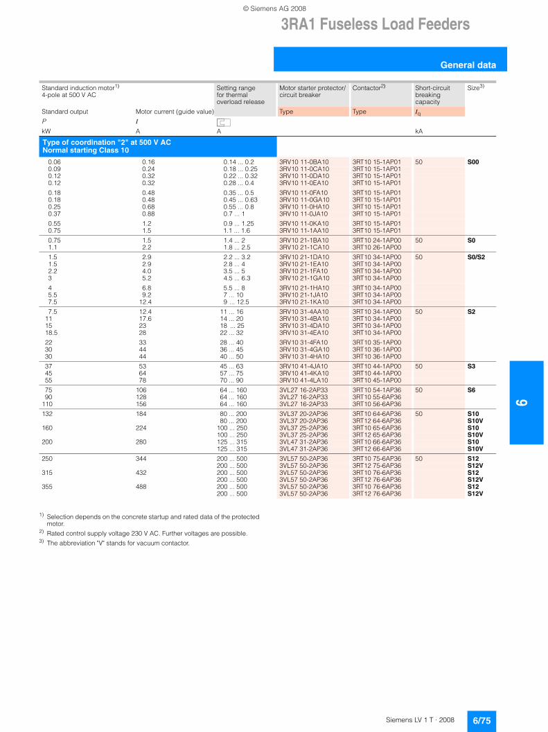
3RA1 Fuseless Load Feeders
6/75Siemens LV 1 T · 2008
6
General data
1) Selection depends on the concrete startup and rated data of the protected motor.
2) Rated control supply voltage 230 V AC. Further voltages are possible.3) The abbreviation "V" stands for vacuum contactor.
Standard induction motor1)
4-pole at 500 V ACSetting range for thermal overload release
Motor starter protector/circuit breaker
Contactor2) Short-circuit breaking capacity
Size3)
Standard output Motor current (guide value) Type Type IqP I
kW A A kA
Type of coordination "2" at 500 V ACNormal starting Class 10
0.06 0.16 0.14 ... 0.2 3RV10 11-0BA10 3RT10 15-1AP01 50 S000.09 0.24 0.18 ... 0.25 3RV10 11-0CA10 3RT10 15-1AP010.12 0.32 0.22 ... 0.32 3RV10 11-0DA10 3RT10 15-1AP010.12 0.32 0.28 ... 0.4 3RV10 11-0EA10 3RT10 15-1AP01
0.18 0.48 0.35 ... 0.5 3RV10 11-0FA10 3RT10 15-1AP010.18 0.48 0.45 ... 0.63 3RV10 11-0GA10 3RT10 15-1AP010.25 0.68 0.55 ... 0.8 3RV10 11-0HA10 3RT10 15-1AP010.37 0.88 0.7 ... 1 3RV10 11-0JA10 3RT10 15-1AP01
0.55 1.2 0.9 ... 1.25 3RV10 11-0KA10 3RT10 15-1AP010.75 1.5 1.1 ... 1.6 3RV10 11-1AA10 3RT10 15-1AP01
0.75 1.5 1.4 ... 2 3RV10 21-1BA10 3RT10 24-1AP00 50 S01.1 2.2 1.8 ... 2.5 3RV10 21-1CA10 3RT10 26-1AP00
1.5 2.9 2.2 ... 3.2 3RV10 21-1DA10 3RT10 34-1AP00 50 S0/S21.5 2.9 2.8 ... 4 3RV10 21-1EA10 3RT10 34-1AP002.2 4.0 3.5 ... 5 3RV10 21-1FA10 3RT10 34-1AP003 5.2 4.5 ... 6.3 3RV10 21-1GA10 3RT10 34-1AP00
4 6.8 5.5 ... 8 3RV10 21-1HA10 3RT10 34-1AP005.5 9.2 7 ... 10 3RV10 21-1JA10 3RT10 34-1AP007.5 12.4 9 ... 12.5 3RV10 21-1KA10 3RT10 34-1AP00
7.5 12.4 11 ... 16 3RV10 31-4AA10 3RT10 34-1AP00 50 S211 17.6 14 ... 20 3RV10 31-4BA10 3RT10 34-1AP0015 23 18 ... 25 3RV10 31-4DA10 3RT10 34-1AP0018.5 28 22 ... 32 3RV10 31-4EA10 3RT10 34-1AP00
22 33 28 ... 40 3RV10 31-4FA10 3RT10 35-1AP0030 44 36 ... 45 3RV10 31-4GA10 3RT10 36-1AP0030 44 40 ... 50 3RV10 31-4HA10 3RT10 36-1AP00
37 53 45 ... 63 3RV10 41-4JA10 3RT10 44-1AP00 50 S345 64 57 ... 75 3RV10 41-4KA10 3RT10 44-1AP0055 78 70 ... 90 3RV10 41-4LA10 3RT10 45-1AP00
75 106 64 ... 160 3VL27 16-2AP33 3RT10 54-1AP36 50 S690 128 64 ... 160 3VL27 16-2AP33 3RT10 55-6AP36
110 156 64 ... 160 3VL27 16-2AP33 3RT10 56-6AP36
132 184 80 ... 200 3VL37 20-2AP36 3RT10 64-6AP36 50 S1080 ... 200 3VL37 20-2AP36 3RT12 64-6AP36 S10V
160 224 100 ... 250 3VL37 25-2AP36 3RT10 65-6AP36 S10100 ... 250 3VL37 25-2AP36 3RT12 65-6AP36 S10V
200 280 125 ... 315 3VL47 31-2AP36 3RT10 66-6AP36 S10125 ... 315 3VL47 31-2AP36 3RT12 66-6AP36 S10V
250 344 200 ... 500 3VL57 50-2AP36 3RT10 75-6AP36 50 S12200 ... 500 3VL57 50-2AP36 3RT12 75-6AP36 S12V
315 432 200 ... 500 3VL57 50-2AP36 3RT10 76-6AP36 S12200 ... 500 3VL57 50-2AP36 3RT12 76-6AP36 S12V
355 488 200 ... 500 3VL57 50-2AP36 3RT10 76-6AP36 S12200 ... 500 3VL57 50-2AP36 3RT12 76-6AP36 S12V
© Siemens AG 2008
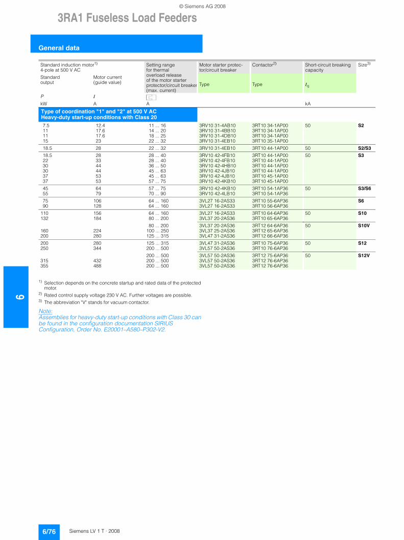
63RA1 Fuseless Load Feeders
General data
6/76 Siemens LV 1 T · 2008
1) Selection depends on the concrete startup and rated data of the protected motor.
2) Rated control supply voltage 230 V AC. Further voltages are possible.3) The abbreviation "V" stands for vacuum contactor.
Note:Assemblies for heavy-duty start-up conditions with Class 30 can be found in the configuration documentation SIRIUS Configuration, Order No. E20001–A580–P302-V2.
Standard induction motor1)
4-pole at 500 V ACSetting range for thermal overload release of the motor starter protector/circuit breaker(max. current)
Motor starter protec-tor/circuit breaker
Contactor2) Short-circuit breaking capacity
Size3)
Standard output
Motor current (guide value) Type Type Iq
P I
kW A A kA
Type of coordination "1" and "2" at 500 V AC Heavy-duty start-up conditions with Class 207.5 12.4 11 ... 16 3RV10 31-4AB10 3RT10 34-1AP00 50 S211 17.6 14 ... 20 3RV10 31-4BB10 3RT10 34-1AP0011 17.6 18 ... 25 3RV10 31-4DB10 3RT10 34-1AP0015 23 22 ... 32 3RV10 31-4EB10 3RT10 35-1AP00
18.5 28 22 ... 32 3RV10 31-4EB10 3RT10 44-1AP00 50 S2/S3
18.5 28 28 ... 40 3RV10 42-4FB10 3RT10 44-1AP00 50 S322 33 28 ... 40 3RV10 42-4FB10 3RT10 44-1AP0030 44 36 ... 50 3RV10 42-4HB10 3RT10 44-1AP0030 44 45 ... 63 3RV10 42-4JB10 3RT10 44-1AP0037 53 45 ... 63 3RV10 42-4JB10 3RT10 45-1AP0037 53 57 ... 75 3RV10 42-4KB10 3RT10 45-1AP00
45 64 57 ... 75 3RV10 42-4KB10 3RT10 54-1AP36 50 S3/S655 79 70 ... 90 3RV10 42-4LB10 3RT10 54-1AP36
75 106 64 ... 160 3VL27 16-2AS33 3RT10 55-6AP36 S690 128 64 ... 160 3VL27 16-2AS33 3RT10 56-6AP36
110 156 64 ... 160 3VL27 16-2AS33 3RT10 64-6AP36 50 S10132 184 80 ... 200 3VL37 20-2AS36 3RT10 65-6AP36
80 ... 200 3VL37 20-2AS36 3RT12 64-6AP36 50 S10V160 224 100 ... 250 3VL37 25-2AS36 3RT12 65-6AP36200 280 125 ... 315 3VL47 31-2AS36 3RT12 66-6AP36
200 280 125 ... 315 3VL47 31-2AS36 3RT10 75-6AP36 50 S12250 344 200 ... 500 3VL57 50-2AS36 3RT10 76-6AP36
200 ... 500 3VL57 50-2AS36 3RT12 75-6AP36 50 S12V315 432 200 ... 500 3VL57 50-2AS36 3RT12 76-6AP36355 488 200 ... 500 3VL57 50-2AS36 3RT12 76-6AP36
© Siemens AG 2008
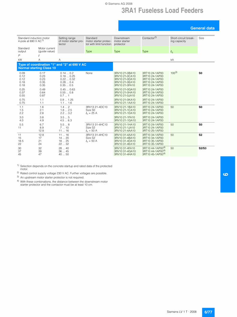
3RA1 Fuseless Load Feeders
6/77Siemens LV 1 T · 2008
6
General data
1) Selection depends on the concrete startup and rated data of the protected motor.
2) Rated control supply voltage 230 V AC. Further voltages are possible.3) An upstream motor starter protector is not required.4) With these combinations, the distance between the downstream motor
starter protector and the contactor must be at least 10 cm.
Standard induction motor 4-pole at 690 V AC1)
Setting range of motor starter pro-tector
Standard motor starter protec-tor with limit function
Downstream motor starter protector
Contactor2) Short-circuit break-ing capacity
Size
Standard output
Motor current (guide value) Type Type Type Iq
P I
kW A A kA
Type of coordination "1" and "2" at 690 V ACNormal starting Class 10
0.09 0.17 0.14 ... 0.2 None 3RV10 21-0BA10 3RT10 24-1AP00 1003) S00.12 0.23 0.18 ... 0.25 3RV10 21-0CA10 3RT10 24-1AP000.12 0.23 0.22 ... 0.32 3RV10 21-0DA10 3RT10 24-1AP000.18 0.35 0.28 ... 0.4 3RV10 21-0EA10 3RT10 24-1AP000.18 0.35 0.35 ... 0.5 3RV10 21-0FA10 3RT10 24-1AP00
0.25 0.49 0.45 ... 0.63 3RV10 21-0GA10 3RT10 24-1AP000.37 0.64 0.55 ... 0.8 3RV10 21-0HA10 3RT10 24-1AP000.55 0.87 0.7 ... 1 3RV10 21-0JA10 3RT10 24-1AP00
0.75 1.1 0.9 ... 1.25 3RV10 21-0KA10 3RT10 24-1AP000.75 1.1 1.1 ... 1.6 3RV10 21-1AA10 3RT10 24-1AP00
1.1 1.6 1.4 ... 2 3RV13 21-4DC10Size S0In = 25 A
3RV10 21-1BA10 3RT10 24-1AP00 50 S01.5 2.1 1.8 ... 2.5 3RV10 21-1CA10 3RT10 24-1AP002.2 2.8 2.2 ... 3.2 3RV10 21-1DA10 3RT10 24-1AP00
3.0 3.8 3.5 ... 5 3RV10 21-1FA10 3RT10 24-1AP004.0 4.9 4.5 ... 6.3 3RV10 21-1GA10 3RT10 24-1AP00
5.5 6.7 5.5 ... 8 3RV13 31-4HC10Size S2In = 50 A
3RV10 21-1HA10 3RT10 24-1AP00 50 S011 8.9 7 ... 10 3RV10 21-1JA10 3RT10 24-1AP00
12.8 11 ... 16 3RV10 21-4AA10 3RT10 25-1AP00
11 12.8 11 ... 16 3RV13 31-4HC10Size S2In = 50 A
3RV10 31-4AA10 3RT10 34-1AP00 50 S215 17 14 ... 20 3RV10 31-4BA10 3RT10 34-1AP0018.5 21 18 ... 25 3RV10 31-4DA10 3RT10 35-1AP0022 24 22 ... 32 3RV10 31-4EA10 3RT10 35-1AP00
30 32 28 ... 40 3RV10 31-4FA10 3RT10 44-1AP004) 50 S2/S337 39 36 ... 45 3RV10 31-4GA10 3RT10 44-1AP004)
45 47 40 ... 50 3RV10 31-4HA10 3RT10 45-1AP004)
© Siemens AG 2008
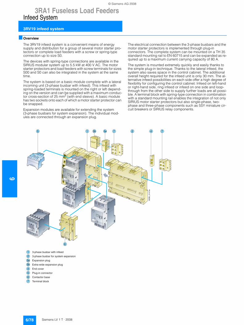
63RA1 Fuseless Load Feeders
Infeed System
3RV19 infeed system
6/78 Siemens LV 1 T · 2008
■ Overview
The 3RV19 infeed system is a convenient means of energy supply and distribution for a group of several motor starter pro-tectors or complete load feeders with a screw or spring-type connection up to size S0.
The devices with spring-type connections are available in the SIRIUS modular system up to 5.5 kW at 400 V AC. The motor starter protectors and load feeders with screw terminals for sizes S00 and S0 can also be integrated in the system at the same time.
The system is based on a basic module complete with a lateral incoming unit (3-phase busbar with infeed). This infeed with spring-loaded terminals is mounted on the right or left depend-ing on the version and can be supplied with a maximum conduc-tor cross-section of 25 mm2 (with end sleeve). A basic module has two sockets onto each of which a motor starter protector can be snapped.
Expansion modules are available for extending the system (3-phase busbars for system expansion). The individual mod-ules are connected through an expansion plug.
The electrical connection between the 3-phase busbars and the motor starter protectors is implemented through plug-in connectors. The complete system can be mounted on a TH 35 standard mounting rail to EN 60715 and can be expanded as re-quired up to a maximum current carrying capacity of 80 A.
The system is mounted extremely quickly and easily thanks to the simple plug-in technique. Thanks to the lateral infeed, the system also saves space in the control cabinet. The additional overall height required for the infeed unit is only 30 mm. The al-ternative infeed possibilities on each side offer a high degree of flexibility for configuring the control cabinet: Infeed on left-hand or right-hand side, ring infeed or infeed on one side and loop-through from the other side to supply further loads are all possi-ble. A terminal block with spring-type connection in combination with a standard mounting rail enables the integration of not only SIRIUS motor starter protectors but also single-phase, two-phase and three-phase components such as 5SY miniature cir-cuit breakers or SIRIUS relay components.
����������
�
�
�
�
�
�
�
� � � �� ��
�
������� �� �������������
������� �� ���������������������
���������!�"
�������������������!�"
���#�$��
%!�"����#����#���
&���#���� ��
'�����!� !�#(
© Siemens AG 2008
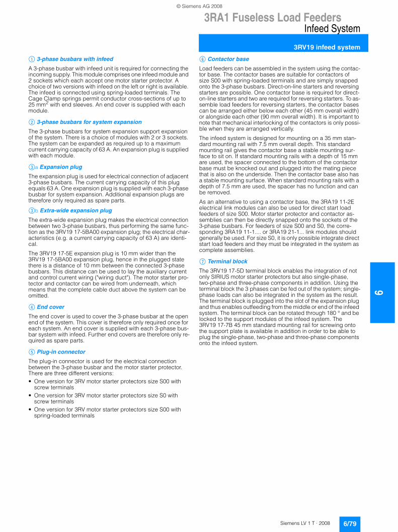
3RA1 Fuseless Load Feeders
6/79Siemens LV 1 T · 2008
6
Infeed System
3RV19 infeed system
$ 3-phase busbars with infeed
A 3-phase busbar with infeed unit is required for connecting the incoming supply. This module comprises one infeed module and 2 sockets which each accept one motor starter protector. A choice of two versions with infeed on the left or right is available. The infeed is connected using spring-loaded terminals. The Cage Clamp springs permit conductor cross-sections of up to 25 mm2 with end sleeves. An end cover is supplied with each module.
% 3-phase busbars for system expansion
The 3-phase busbars for system expansion support expansion of the system. There is a choice of modules with 2 or 3 sockets. The system can be expanded as required up to a maximum current carrying capacity of 63 A. An expansion plug is supplied with each module.
&a Expansion plug
The expansion plug is used for electrical connection of adjacent 3-phase busbars. The current carrying capacity of this plug equals 63 A. One expansion plug is supplied with each 3-phase busbar for system expansion. Additional expansion plugs are therefore only required as spare parts.
&b Extra-wide expansion plug
The extra-wide expansion plug makes the electrical connection between two 3-phase busbars, thus performing the same func-tion as the 3RV19 17-5BA00 expansion plug; the electrical char-acteristics (e.g. a current carrying capacity of 63 A) are identi-cal.
The 3RV19 17-5E expansion plug is 10 mm wider than the 3RV19 17-5BA00 expansion plug, hence in the plugged state there is a distance of 10 mm between the connected 3-phase busbars. This distance can be used to lay the auxiliary current and control current wiring ("wiring duct"). The motor starter pro-tector and contactor can be wired from underneath, which means that the complete cable duct above the system can be omitted.
( End cover
The end cover is used to cover the 3-phase busbar at the open end of the system. This cover is therefore only required once for each system. An end cover is supplied with each 3-phase bus-bar system with infeed. Further end covers are therefore only re-quired as spare parts.
) Plug-in connector
The plug-in connector is used for the electrical connection between the 3-phase busbar and the motor starter protector. There are three different versions:• One version for 3RV motor starter protectors size S00 with
screw terminals• One version for 3RV motor starter protectors size S0 with
screw terminals• One version for 3RV motor starter protectors size S00 with
spring-loaded terminals
* Contactor base
Load feeders can be assembled in the system using the contac-tor base. The contactor bases are suitable for contactors of size S00 with spring-loaded terminals and are simply snapped onto the 3-phase busbars. Direct-on-line starters and reversing starters are possible. One contactor base is required for direct-on-line starters and two are required for reversing starters. To as-semble load feeders for reversing starters, the contactor bases can be arranged either below each other (45 mm overall width) or alongside each other (90 mm overall width). It is important to note that mechanical interlocking of the contactors is only possi-ble when they are arranged vertically.
The infeed system is designed for mounting on a 35 mm stan-dard mounting rail with 7.5 mm overall depth. This standard mounting rail gives the contactor base a stable mounting sur-face to sit on. If standard mounting rails with a depth of 15 mm are used, the spacer connected to the bottom of the contactor base must be knocked out and plugged into the mating piece that is also on the underside. Then the contactor base also has a stable mounting surface. When standard mounting rails with a depth of 7.5 mm are used, the spacer has no function and can be removed.
As an alternative to using a contactor base, the 3RA19 11-2E electrical link modules can also be used for direct start load feeders of size S00. Motor starter protector and contactor as-semblies can then be directly snapped onto the sockets of the 3-phase busbars. For feeders of size S00 and S0, the corre-sponding 3RA19 11-1.... or 3RA19 21-1... link modules should generally be used. For size S0, it is only possible integrate direct start load feeders and they must be integrated in the system as complete assemblies.
+ Terminal block
The 3RV19 17-5D terminal block enables the integration of not only SIRIUS motor starter protectors but also single-phase, two-phase and three-phase components in addition. Using the terminal block the 3 phases can be fed out of the system; single-phase loads can also be integrated in the system as the result. The terminal block is plugged into the slot of the expansion plug and thus enables outfeeding from the middle or end of the infeed system. The terminal block can be rotated through 180 ° and be locked to the support modules of the infeed system. The 3RV19 17-7B 45 mm standard mounting rail for screwing onto the support plate is available in addition in order to be able to plug the single-phase, two-phase and three-phase components onto the infeed system.
© Siemens AG 2008
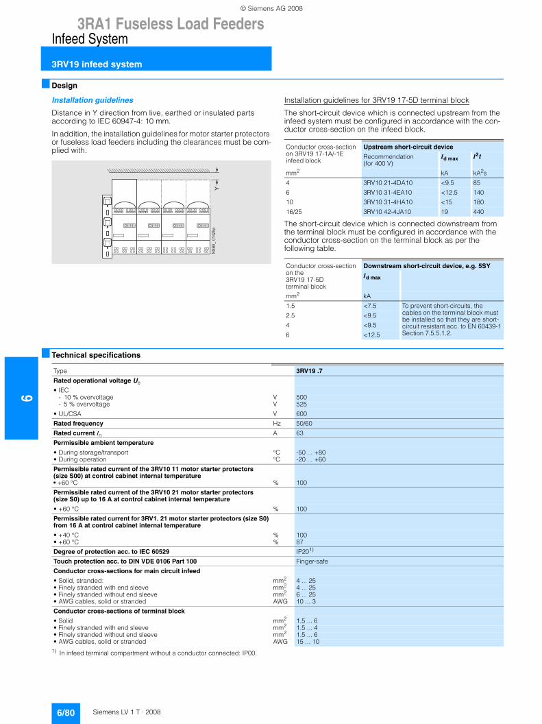
63RA1 Fuseless Load Feeders
Infeed System
3RV19 infeed system
6/80 Siemens LV 1 T · 2008
■ Design
Installation guidelines
Distance in Y direction from live, earthed or insulated parts according to IEC 60947-4: 10 mm.
In addition, the installation guidelines for motor starter protectors or fuseless load feeders including the clearances must be com-plied with.
Installation guidelines for 3RV19 17-5D terminal block
The short-circuit device which is connected upstream from the infeed system must be configured in accordance with the con-ductor cross-section on the infeed block.
The short-circuit device which is connected downstream from the terminal block must be configured in accordance with the conductor cross-section on the terminal block as per the following table.
■ Technical specifications
1) In infeed terminal compartment without a conductor connected: IP00.
( ( ( (
*������������
Conductor cross-section on 3RV19 17-1A/-1E infeed block
Upstream short-circuit device
Recommendation (for 400 V)
Id max I2t
mm2 kA kA2s
4 3RV10 21-4DA10 <9.5 85
6 3RV10 31-4EA10 <12.5 140
10 3RV10 31-4HA10 <15 180
16/25 3RV10 42-4JA10 19 440
Conductor cross-section on the 3RV19 17-5Dterminal block
Downstream short-circuit device, e.g. 5SY
Id max
mm2 kA
1.5 <7.5 To prevent short-circuits, the cables on the terminal block must be installed so that they are short-circuit resistant acc. to EN 60439-1 Section 7.5.5.1.2.
2.5 <9.5
4 <9.5
6 <12.5
Type 3RV19 .7
Rated operational voltage Ue
• IEC- 10 % overvoltage V 500- 5 % overvoltage V 525
• UL/CSA V 600
Rated frequency Hz 50/60
Rated current In A 63
Permissible ambient temperature
• During storage/transport °C -50 ... +80• During operation °C -20 ... +60
Permissible rated current of the 3RV10 11 motor starter protectors (size S00) at control cabinet internal temperature• +60 °C % 100
Permissible rated current of the 3RV10 21 motor starter protectors (size S0) up to 16 A at control cabinet internal temperature
• +60 °C % 100
Permissible rated current for 3RV1. 21 motor starter protectors (size S0) from 16 A at control cabinet internal temperature
• +40 °C % 100• +60 °C % 87
Degree of protection acc. to IEC 60529 IP201)
Touch protection acc. to DIN VDE 0106 Part 100 Finger-safe
Conductor cross-sections for main circuit infeed
• Solid, stranded: mm2 4 ... 25• Finely stranded with end sleeve mm2 4 ... 25• Finely stranded without end sleeve mm2 6 ... 25• AWG cables, solid or stranded AWG 10 ... 3
Conductor cross-sections of terminal block
• Solid mm2 1.5 ... 6• Finely stranded with end sleeve mm2 1.5 ... 4• Finely stranded without end sleeve mm2 1.5 ... 6• AWG cables, solid or stranded AWG 15 ... 10
© Siemens AG 2008
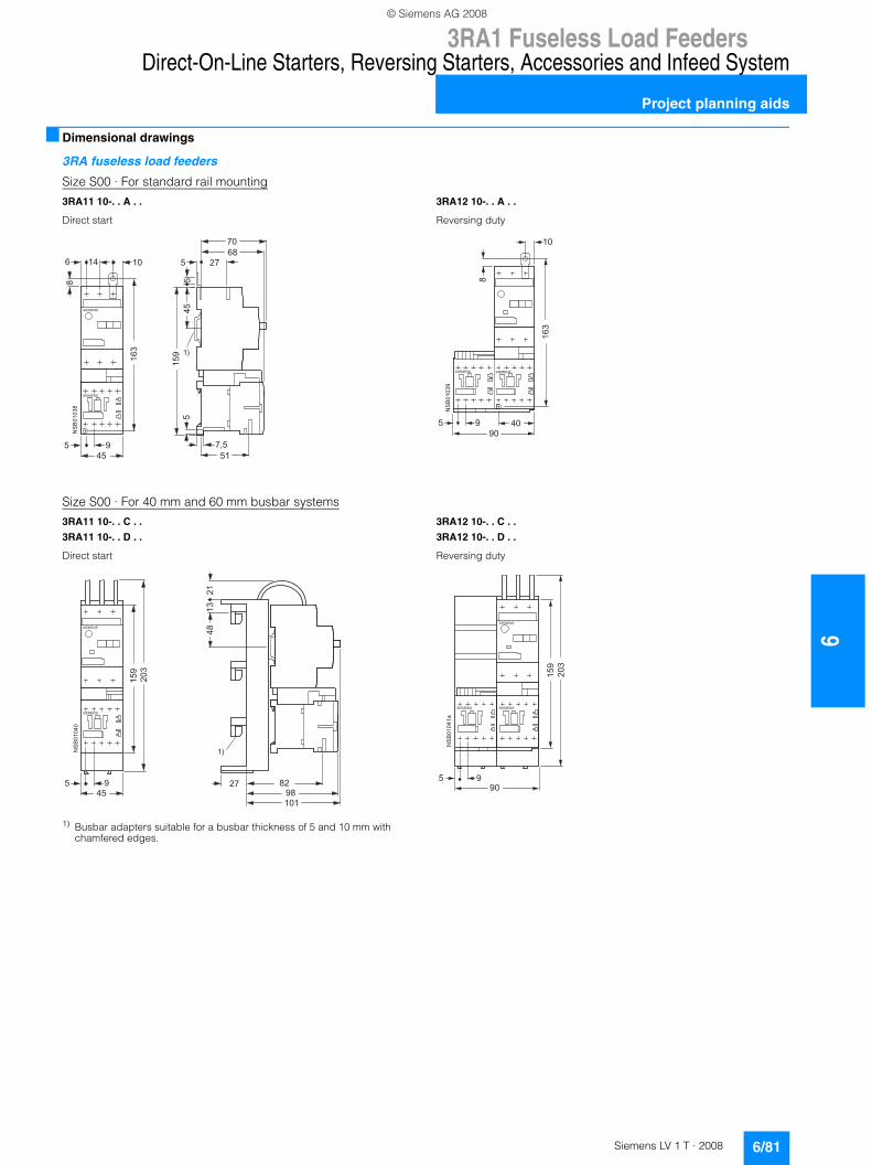
3RA1 Fuseless Load Feeders
6/81Siemens LV 1 T · 2008
6
Direct-On-Line Starters, Reversing Starters, Accessories and Infeed System
Project planning aids
■ Dimensional drawings
3RA fuseless load feeders
Size S00 · For standard rail mounting
Size S00 · For 40 mm and 60 mm busbar systems
1) Busbar adapters suitable for a busbar thickness of 5 and 10 mm with chamfered edges.
3RA11 10-. . A . . 3RA12 10-. . A . .
Direct start Reversing duty
���
���
�
� �� ��
�
���
��
��
��
�
� ����
� �����
� �����
��
��
��
��
��
���
� ��
���
�
��
��
��
��
��
� ����� � �����
3RA11 10-. . C . .
3RA11 10-. . D . .
3RA12 10-. . C . .
3RA12 10-. . D . .
Direct start Reversing duty
���
���
�
��
��
� �����
� �����
��
��
��
��
���
�
��
��
�������
���
��
� �����
� �����
���
�
� �����
��
��
��
��
�
�
© Siemens AG 2008
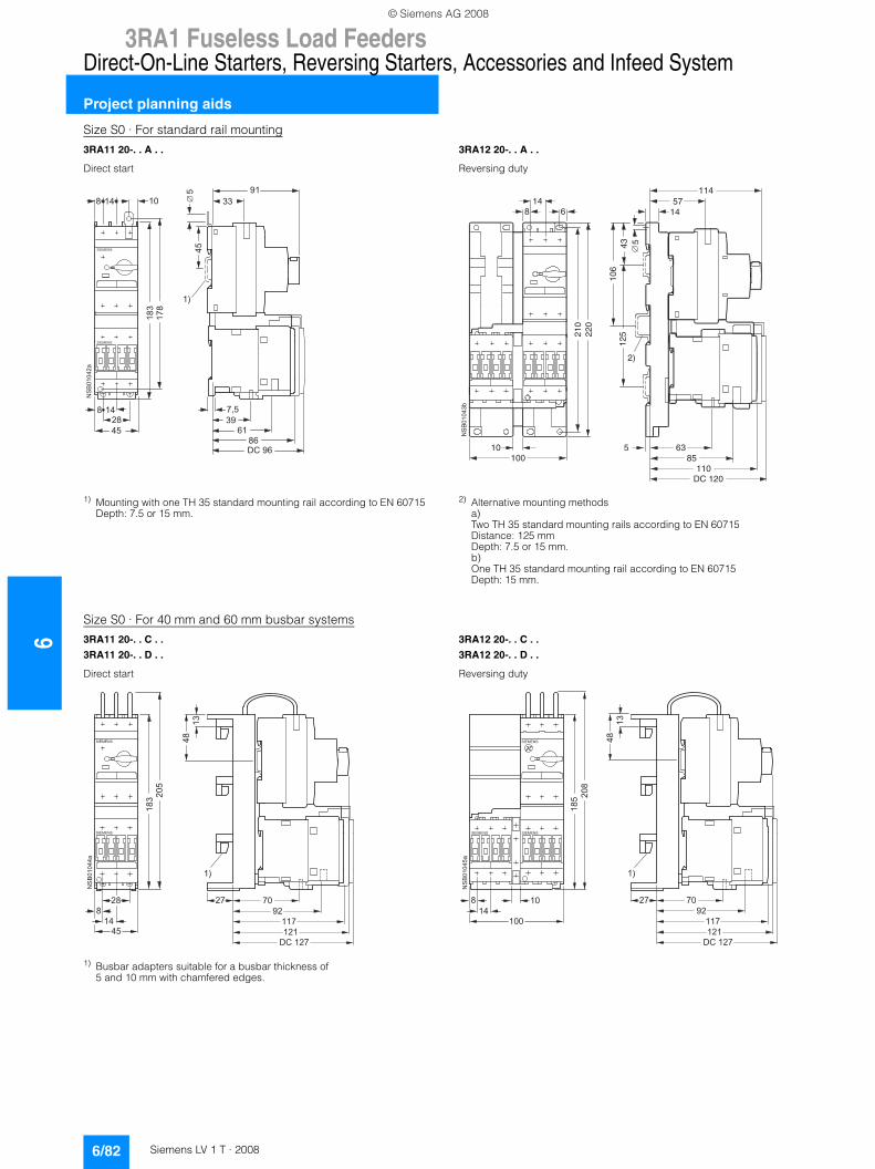
63RA1 Fuseless Load Feeders
Direct-On-Line Starters, Reversing Starters, Accessories and Infeed System
Project planning aids
6/82 Siemens LV 1 T · 2008
Size S0 · For standard rail mounting
1) Mounting with one TH 35 standard mounting rail according to EN 60715 Depth: 7.5 or 15 mm.
2) Alternative mounting methodsa)Two TH 35 standard mounting rails according to EN 60715 Distance: 125 mm Depth: 7.5 or 15 mm.b)One TH 35 standard mounting rail according to EN 60715 Depth: 15 mm.
Size S0 · For 40 mm and 60 mm busbar systems
1) Busbar adapters suitable for a busbar thickness of 5 and 10 mm with chamfered edges.
3RA11 20-. . A . . 3RA12 20-. . A . .
Direct start Reversing duty
� �� �� ���
����
���
��
���
���������
��
��
��
��
���
� �����
� ����� ��
���
��
�
�
10100
5
DC 120110
8563
6814
1457
114
210
220
106
125
43
NS
B01
043b
2)
5�
3RA11 20-. . C . .
3RA11 20-. . D . .
3RA12 20-. . C . .
3RA12 20-. . D . .
Direct start Reversing duty
���
��
��
��
��
��
�
� �����
� �����
���
��
��
��
�
��
�
���
����
�����
��
�
��
��
��
��
�
� �����
� �����
��� ��
��
�
���
� �����
��
�
���
��
��
��
� ���
��
�����
© Siemens AG 2008
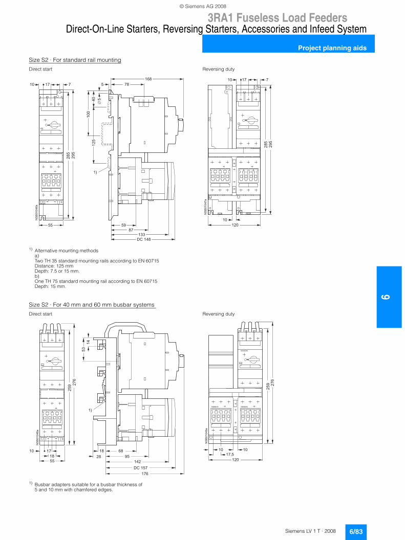
3RA1 Fuseless Load Feeders
6/83Siemens LV 1 T · 2008
6
Direct-On-Line Starters, Reversing Starters, Accessories and Infeed System
Project planning aids
Size S2 · For standard rail mounting
1) Alternative mounting methodsa)Two TH 35 standard mounting rails according to EN 60715 Distance: 125 mm Depth: 7.5 or 15 mm.b)One TH 75 standard mounting rail according to EN 60715 Depth: 15 mm.
Size S2 · For 40 mm and 60 mm busbar systems
1) Busbar adapters suitable for a busbar thickness of 5 and 10 mm with chamfered edges.
Direct start Reversing duty
��
��
��
���
��
������
����
��
���
���
�� �
��
���
�
���
��
� �
���
�
��
��
��
��
���
���
���
�� �
��
Direct start Reversing duty
��
��
��
���
���
��
����
� ��
�����
��
��
�����
��
��
��
��
��
���
���
��
��
��
��
���
��
� �����
� ������ �����
��
��
© Siemens AG 2008
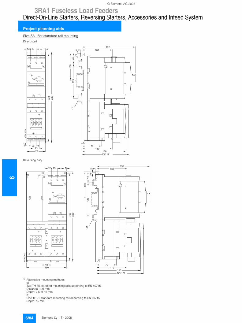
63RA1 Fuseless Load Feeders
Direct-On-Line Starters, Reversing Starters, Accessories and Infeed System
Project planning aids
6/84 Siemens LV 1 T · 2008
Size S3 · For standard rail mounting
1) Alternative mounting methodsa)Two TH 35 standard mounting rails according to EN 60715 Distance: 125 mm Depth: 7.5 or 15 mm.b)One TH 75 standard mounting rail according to EN 60715 Depth: 15 mm.
Direct start
Reversing duty
��
��
��
���
���
�� ��
��
���
������
��
�
���
�
�����
�
��
��
��
�
��
����
��
�
�
��
���
���
��
�
���
�
�����
�
��
��
��
��
��
��
���
�����
���
���
�� �� ���
�
© Siemens AG 2008
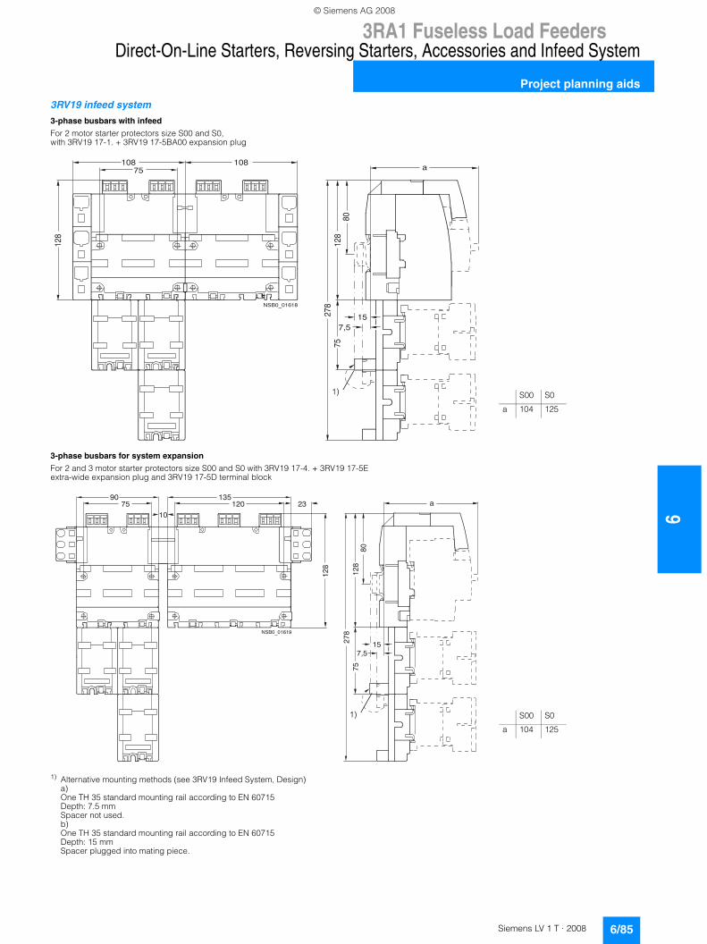
3RA1 Fuseless Load Feeders
6/85Siemens LV 1 T · 2008
6
Direct-On-Line Starters, Reversing Starters, Accessories and Infeed System
Project planning aids
3RV19 infeed system
1) Alternative mounting methods (see 3RV19 Infeed System, Design)a) One TH 35 standard mounting rail according to EN 60715 Depth: 7.5 mmSpacer not used.b)One TH 35 standard mounting rail according to EN 60715 Depth: 15 mm Spacer plugged into mating piece.
3-phase busbars with infeed
For 2 motor starter protectors size S00 and S0, with 3RV19 17-1. + 3RV19 17-5BA00 expansion plug
3-phase busbars for system expansion
For 2 and 3 motor starter protectors size S00 and S0 with 3RV19 17-4. + 3RV19 17-5E extra-wide expansion plug and 3RV19 17-5D terminal block
128
108 108
8075
128
15278
7,5
a75
NSB0_01618
1)
23
10
90 135
128
75 120 a
7,5
278
15
128
7580
NSB0_01619
1)
S00 S0
a 104 125
S00 S0
a 104 125
© Siemens AG 2008
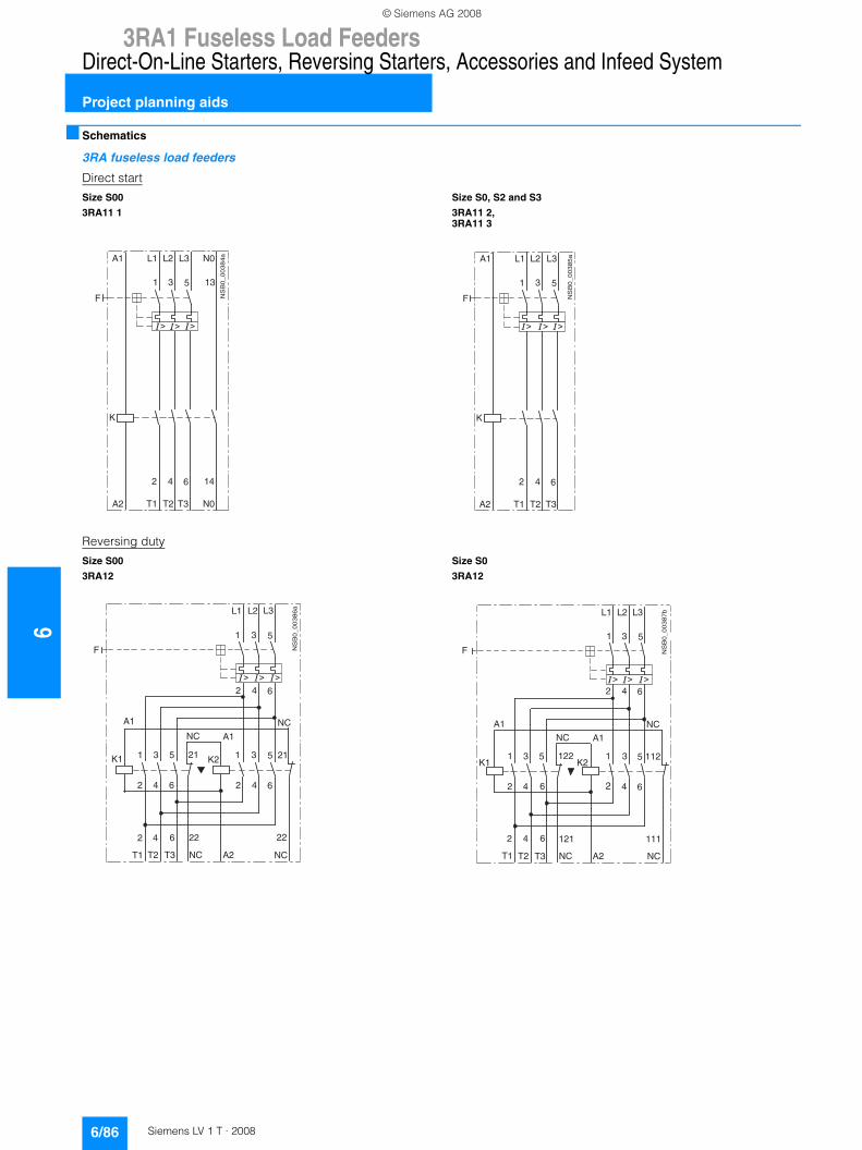
63RA1 Fuseless Load Feeders
Direct-On-Line Starters, Reversing Starters, Accessories and Infeed System
Project planning aids
6/86 Siemens LV 1 T · 2008
■ Schematics
3RA fuseless load feeders
Direct start
Reversing duty
Size S00
3RA11 1
Size S0, S2 and S3
3RA11 2, 3RA11 3
Size S00
3RA12
Size S0
3RA12
NS
B0_
00
38
4a
1 3 5
L1 L2 L3 N0A1
13
F
K
2 4 6
T1 T2 T3 N0A2
14
NS
B0_
003
85
a
1 3 5
L1 L2 L3A1
F
K
2 4 6
T1 T2 T3A2
NS
B0_
00
38
6a
1 3 5
L1 L2 L3
A1
F
2 4 6
1 3 5
2 4 62 4 6
21
22
T1 T2 T3 NC
2 4 6
K1
A1
K2
A2
1 3 5
NC
NC
NC
22
21
NS
B0_
00
387
b
1 3 5
L1 L2 L3
A1
F
2 4 6
1 3 5
2 4 62 4 6
122
111
T1 T2 T3 NC
2 4 6
K1
A1
K2
A2
1 3 5
NCNC
NC
121
112
© Siemens AG 2008
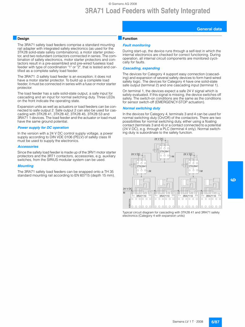
3RA71 Load Feeders with Safety Integrated
6/87Siemens LV 1 T · 2008
6
General data
■ Design
The 3RA71 safety load feeders comprise a standard mounting rail adapter with integrated safety electronics (as used for the 3TK28 solid-state safety combinations), a motor starter protec-tor, and two redundant contactors connected in series. The com-bination of safety electronics, motor starter protectors and con-tactors result in a pre-assembled and pre-wired fuseless load feeder with type of coordination "1" or "2", that is tested and cer-tified as a complete safety load feeder.
The 3RA71 .0 safety load feeder is an exception; it does not have a motor starter protector. To build up a complete load feeder, it must be connected in series with a fuse or motor starter protector.
The load feeder has a safe solid-state output, a safe input for cascading and an input for normal switching duty. Three LEDs on the front indicate the operating state.
Expansion units as well as actuators or load feeders can be con-nected to safe output 2. Safe output 2 can also be used for cas-cading with 3TK28 41, 3TK28 42, 3TK28 45, 3TK28 53 and 3RA71 1 devices. The load feeder and the actuator or load must have the same ground potential.
Power supply for DC operation
In the version with a 24 V DC control supply voltage, a power supply according to DIN VDE 0106 (PELV) of safety class III must be used to supply the electronics.
Accessories
Since the safety load feeder is made up of the 3RV1 motor starter protectors and the 3RT1 contactors, accessories, e.g. auxiliary switches, from the SIRIUS modular system can be used.
Mounting
The 3RA71 safety load feeders can be snapped onto a TH 35 standard mounting rail according to EN 60715 (depth 15 mm).
■ Function
Fault monitoring
During start-up, the device runs through a self-test in which the internal electronics are checked for correct functioning. During operation, all internal circuit components are monitored cycli-cally for faults.
Cascading, expanding
The devices for Category 4 support easy connection (cascad-ing) and expansion of several safety devices to form hard-wired safety logic. The devices for Category 4 have one solid-state safe output (terminal 2) and one cascading input (terminal 1).
On terminal 1, the devices expect a safe 24 V signal which is safely evaluated. If this signal is missing, the device switches off safely. The switch-on conditions are the same as the conditions for sensor switch-off (EMERGENCY-STOP actuation).
Normal switching duty
In the devices for Category 4, terminals 3 and 4 can be used for normal switching duty (On/Off) of the contactors. There are two possibilities for normal switching duty, either using a floating contact (terminals 3 and 4) or a contact connected to a potential (24 V DC), e.g. through a PLC (terminal 4 only). Normal switch-ing duty is subordinate to the safety function.
Typical circuit diagram for cascading with 3TK28 41 and 3RA71 safety electronics (Category 4 with expansion units)
������� �������
�����
�
� ������ ����� � ������ �����
�����
�
�����
�
�������
�����
�
��
����
���
© Siemens AG 2008
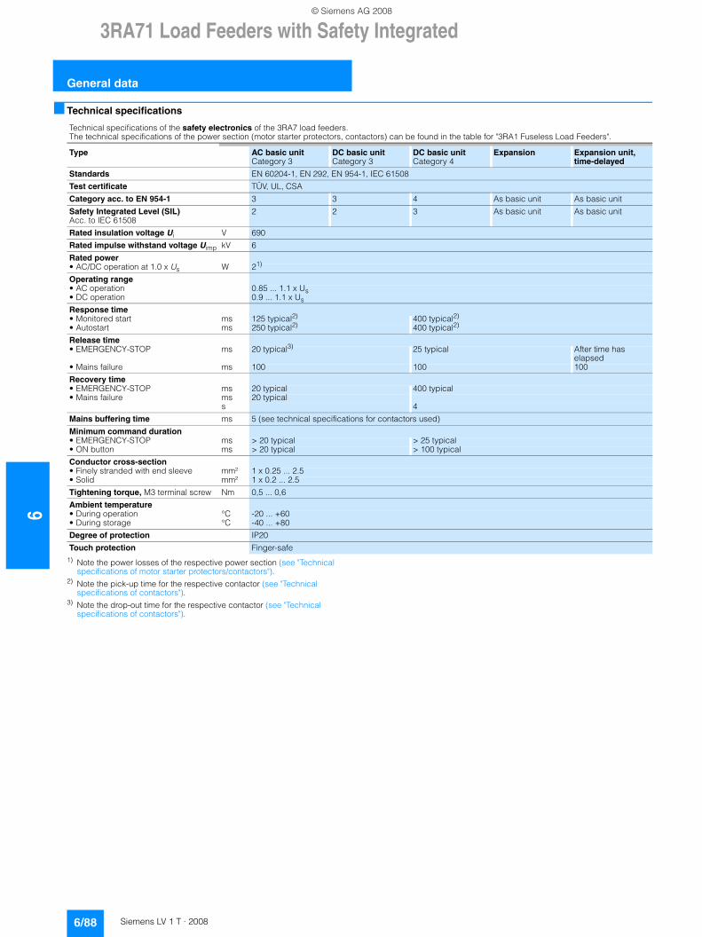
63RA71 Load Feeders with Safety Integrated
General data
6/88 Siemens LV 1 T · 2008
■ Technical specifications
1) Note the power losses of the respective power section (see "Technical specifications of motor starter protectors/contactors").
2) Note the pick-up time for the respective contactor (see "Technical specifications of contactors").
3) Note the drop-out time for the respective contactor (see "Technical specifications of contactors").
Technical specifications of the safety electronics of the 3RA7 load feeders.The technical specifications of the power section (motor starter protectors, contactors) can be found in the table for "3RA1 Fuseless Load Feeders".
Type AC basic unitCategory 3
DC basic unitCategory 3
DC basic unitCategory 4
Expansion Expansion unit, time-delayed
Standards EN 60204-1, EN 292, EN 954-1, IEC 61508
Test certificate TÜV, UL, CSA
Category acc. to EN 954-1 3 3 4 As basic unit As basic unit
Safety Integrated Level (SIL)Acc. to IEC 61508
2 2 3 As basic unit As basic unit
Rated insulation voltage Ui V 690
Rated impulse withstand voltage Uimp kV 6
Rated power• AC/DC operation at 1.0 x Us W 21)
Operating range• AC operation 0.85 ... 1.1 x Us• DC operation 0.9 ... 1.1 x Us
Response time• Monitored start ms 125 typical2) 400 typical2)
• Autostart ms 250 typical2) 400 typical2)
Release time• EMERGENCY-STOP ms 20 typical3) 25 typical After time has
elapsed• Mains failure ms 100 100 100
Recovery time• EMERGENCY-STOP ms 20 typical 400 typical• Mains failure ms 20 typical
s 4
Mains buffering time ms 5 (see technical specifications for contactors used)
Minimum command duration• EMERGENCY-STOP ms > 20 typical > 25 typical• ON button ms > 20 typical > 100 typical
Conductor cross-section• Finely stranded with end sleeve mm² 1 x 0.25 ... 2.5• Solid mm² 1 x 0.2 ... 2.5
Tightening torque, M3 terminal screw Nm 0,5 ... 0,6
Ambient temperature• During operation °C -20 ... +60• During storage °C -40 ... +80
Degree of protection IP20
Touch protection Finger-safe
© Siemens AG 2008
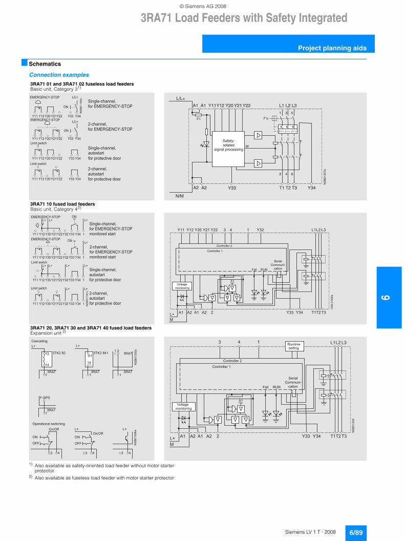
3RA71 Load Feeders with Safety Integrated
6/89Siemens LV 1 T · 2008
6
Project planning aids
■ Schematics
Connection examples
1) Also available as safety-oriented load feeder without motor starter protector.
2) Also available as fuseless load feeder with motor starter protector.
3RA71 01 and 3RA71 02 fuseless load feeders Basic unit, Category 31)
3RA71 10 fused load feeders Basic unit, Category 42)
3RA71 20, 3RA71 30 and 3RA71 40 fused load feeders Expansion unit 2)
� � � � � � � � � � � � � � � � � � � � �
�������
� � � � � � � � � � � � � � � � � � � � �
� � � � � � � � � � � � � � � � � � � � �
� � � � � � � � � � � � � � � � � � � � �
� � �
� � �
� � � � � � � � � � � � � �
� � � � � � � � � � � � � � �
! " # � � � � � � � � � � � � � �
� � � � � � � � � � � � � �
� � � � � � � � � �
! " # � � � � � � � � � � � � � �
� � $ � % # & ' � % � �
� � � � � � � � � � � � � � �
� ( % ! & % � " %
! " # ) " ! % � � % � * � # + ! ! "
� � $ � % # & ' � % � �
� � � � � � � � � �
� ( % ! & % � " %
! " # ) " ! % � � % � * � # + ! ! "
� �
� � �� �
Y33 Y34T1 T2 T3A2A2
1 3 5
F
M
F1
L/L+
N/M
A1 A1 Y11Y12 Y20 Y21 Y22
2 4 6
L1 L2 L3
NS
B01
307a
Safety-related
signal processing
� � � � � �
� � � � � � � � , � � � � � � � � � � � �
�������
�
� �
� � �
� � � � � � � � , � � � � � � � � � � � � �
� �
� � �
� � � � � � � � , � � � � � � � � � � � � �� � �
� �� �
� � � � � � � � , � � � � � � � � � � � � �� � �
� �� �
� �
� � � �
� �� � � � � � � � � � � � � �
� � � � � � � � � � � � � � �
! " # � � � � � � � � � � � � � �
$ ! � � % ! " � + # & % � " %
� � � � � � � � � � � � � �
� � � � � � � � � �
! " # � � � � � � � � � � � � � �
$ ! � � % ! " � + # & % � " %
� � $ � % # & ' � % � �
� � � � � � � � � � � � � � �
� ( % ! & % � " %
! " # ) " ! % � � % � * � # + ! ! "
� � $ � % # & ' � % � �
� � � � � � � � � �
� ( % ! & % � " %
! " # ) " ! % � � % � * � # + ! ! "
� �
� �
��#����-�
� ! � % " ! � � � " # �
� ! � % " ! � � � " # �
� � " � � �
� ! $ $ ( � � �
� � % � ! �. � � � � / �
0 �
0 � 0 � 0 � 0 � �� �
�
� � � � � � � � � � � �
� � � � � �� � ����� � �� � �� � �� � � � � ,
1 ! � % � � �
$ ! � � % ! " � � �
������,�
� �
� �
� �
�� � 0 2
� � 3 � # - �0 �
�� � 0 2
� � 3 � # - � �
� �
�
�� � 0 2
�� � 0 2
�� � 0 2
. � � � �
� �
� � & � � + � � �
� � � � � �
������4�
� � � �
� ) � " � % � ! � � � # & ' � % � � � � �
� � �
� � �
� �
� . .
� �
� . .
������
� ! � % " ! � � � " # �
� ! � % " ! � � � " # �
� � " � � �
� ! $ $ ( � � �
� � % � ! �. � � � � / �
0 �
0 � 0 � 0 � 0 � �� �
�
� � � � � � � � � � � �
� � � � � ����
1 ! � % � � �
$ ! � � % ! " � � �
� ( � % � $ �
& � % % � � �
© Siemens AG 2008
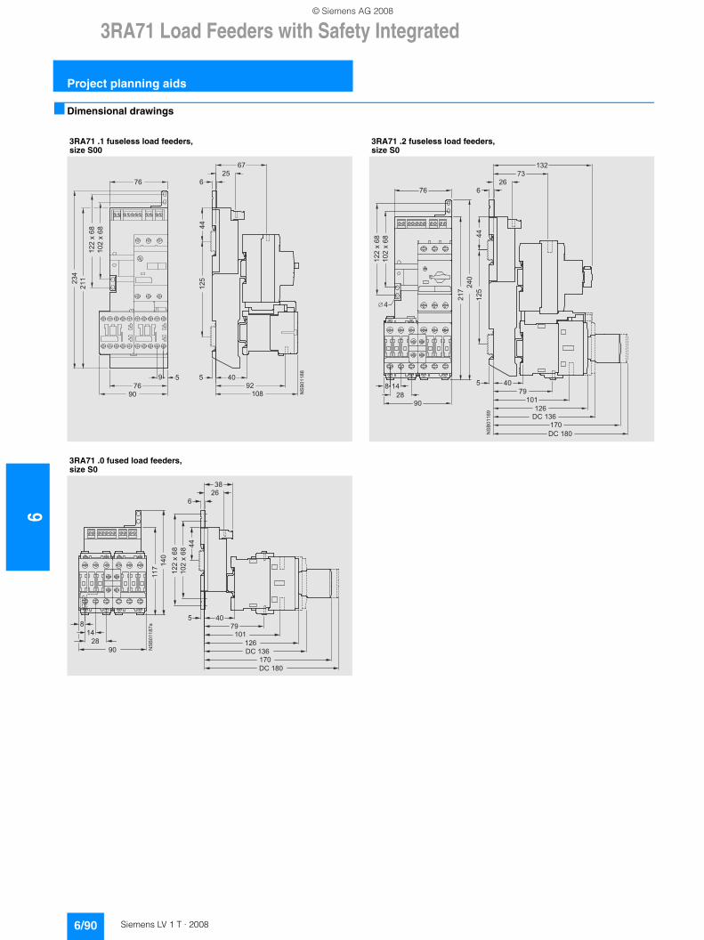
63RA71 Load Feeders with Safety Integrated
Project planning aids
6/90 Siemens LV 1 T · 2008
■ Dimensional drawings
3RA71 .1 fuseless load feeders, size S00
3RA71 .2 fuseless load feeders, size S0
3RA71 .0 fused load feeders, size S0
��
��
��
��
���
��
�
� ���
���
�
���
�
��
��
�
��
����
���
����
� ���
��
��
�
��
��
�
�
�
���
�����
�� ������� ���
�
�����
���
�
���
��
��
��
��
��
���
�
��
��
�
�
���
����
������� ��
����� ���
����
��
����
�
��
��
��
��
�
© Siemens AG 2008
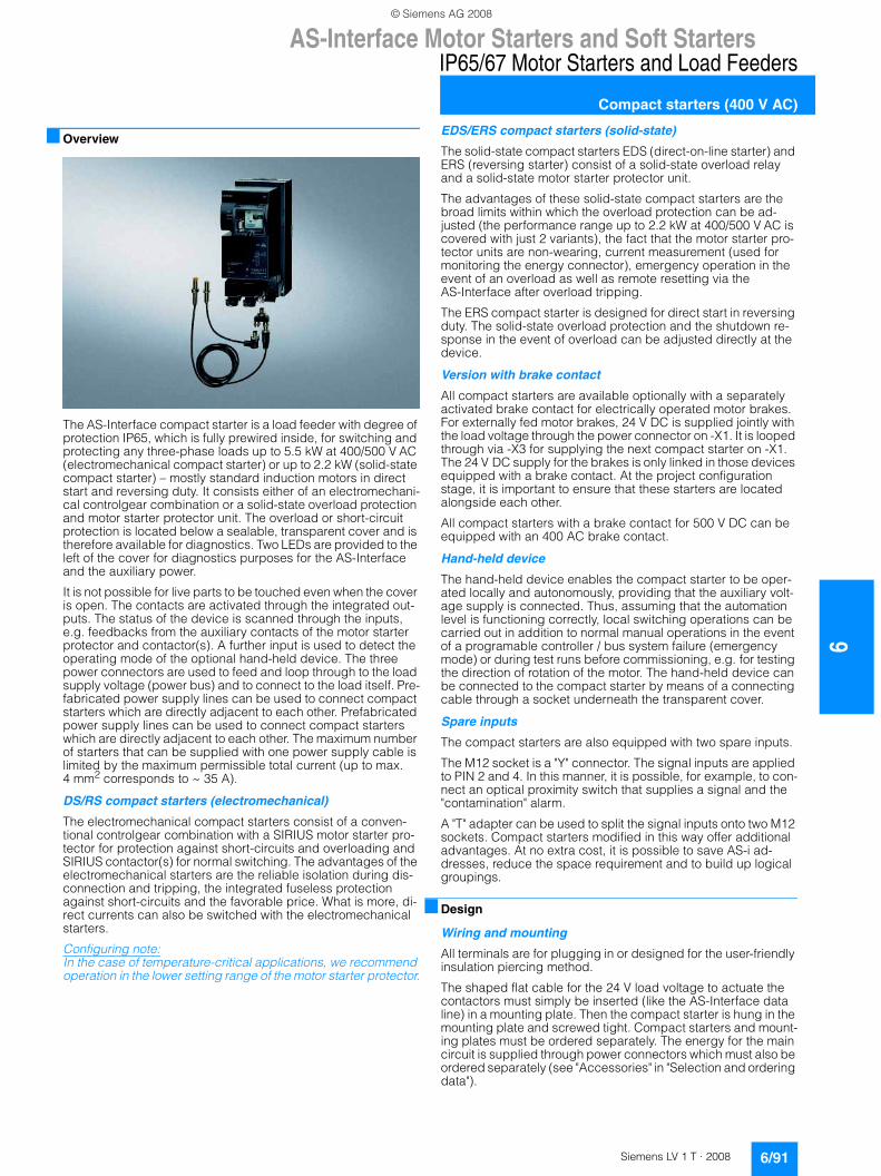
AS-Interface Motor Starters and Soft Starters
6/91Siemens LV 1 T · 2008
6
IP65/67 Motor Starters and Load Feeders
Compact starters (400 V AC)
■ Overview
The AS-Interface compact starter is a load feeder with degree of protection IP65, which is fully prewired inside, for switching and protecting any three-phase loads up to 5.5 kW at 400/500 V AC (electromechanical compact starter) or up to 2.2 kW (solid-state compact starter) – mostly standard induction motors in direct start and reversing duty. It consists either of an electromechani-cal controlgear combination or a solid-state overload protection and motor starter protector unit. The overload or short-circuit protection is located below a sealable, transparent cover and is therefore available for diagnostics. Two LEDs are provided to the left of the cover for diagnostics purposes for the AS-Interface and the auxiliary power.
It is not possible for live parts to be touched even when the cover is open. The contacts are activated through the integrated out-puts. The status of the device is scanned through the inputs, e.g. feedbacks from the auxiliary contacts of the motor starter protector and contactor(s). A further input is used to detect the operating mode of the optional hand-held device. The three power connectors are used to feed and loop through to the load supply voltage (power bus) and to connect to the load itself. Pre-fabricated power supply lines can be used to connect compact starters which are directly adjacent to each other. Prefabricated power supply lines can be used to connect compact starters which are directly adjacent to each other. The maximum number of starters that can be supplied with one power supply cable is limited by the maximum permissible total current (up to max. 4 mm2 corresponds to ~ 35 A).
DS/RS compact starters (electromechanical)
The electromechanical compact starters consist of a conven-tional controlgear combination with a SIRIUS motor starter pro-tector for protection against short-circuits and overloading and SIRIUS contactor(s) for normal switching. The advantages of the electromechanical starters are the reliable isolation during dis-connection and tripping, the integrated fuseless protection against short-circuits and the favorable price. What is more, di-rect currents can also be switched with the electromechanical starters.
Configuring note: In the case of temperature-critical applications, we recommend operation in the lower setting range of the motor starter protector.
EDS/ERS compact starters (solid-state)
The solid-state compact starters EDS (direct-on-line starter) and ERS (reversing starter) consist of a solid-state overload relay and a solid-state motor starter protector unit.
The advantages of these solid-state compact starters are the broad limits within which the overload protection can be ad-justed (the performance range up to 2.2 kW at 400/500 V AC is covered with just 2 variants), the fact that the motor starter pro-tector units are non-wearing, current measurement (used for monitoring the energy connector), emergency operation in the event of an overload as well as remote resetting via the AS-Interface after overload tripping.
The ERS compact starter is designed for direct start in reversing duty. The solid-state overload protection and the shutdown re-sponse in the event of overload can be adjusted directly at the device.
Version with brake contact
All compact starters are available optionally with a separately activated brake contact for electrically operated motor brakes. For externally fed motor brakes, 24 V DC is supplied jointly with the load voltage through the power connector on -X1. It is looped through via -X3 for supplying the next compact starter on -X1. The 24 V DC supply for the brakes is only linked in those devices equipped with a brake contact. At the project configuration stage, it is important to ensure that these starters are located alongside each other.
All compact starters with a brake contact for 500 V DC can be equipped with an 400 AC brake contact.
Hand-held device
The hand-held device enables the compact starter to be oper-ated locally and autonomously, providing that the auxiliary volt-age supply is connected. Thus, assuming that the automation level is functioning correctly, local switching operations can be carried out in addition to normal manual operations in the event of a programable controller / bus system failure (emergency mode) or during test runs before commissioning, e.g. for testing the direction of rotation of the motor. The hand-held device can be connected to the compact starter by means of a connecting cable through a socket underneath the transparent cover.
Spare inputs
The compact starters are also equipped with two spare inputs.
The M12 socket is a "Y" connector. The signal inputs are applied to PIN 2 and 4. In this manner, it is possible, for example, to con-nect an optical proximity switch that supplies a signal and the "contamination" alarm.
A "T" adapter can be used to split the signal inputs onto two M12 sockets. Compact starters modified in this way offer additional advantages. At no extra cost, it is possible to save AS-i ad-dresses, reduce the space requirement and to build up logical groupings.
■ Design
Wiring and mounting
All terminals are for plugging in or designed for the user-friendly insulation piercing method.
The shaped flat cable for the 24 V load voltage to actuate the contactors must simply be inserted (like the AS-Interface data line) in a mounting plate. Then the compact starter is hung in the mounting plate and screwed tight. Compact starters and mount-ing plates must be ordered separately. The energy for the main circuit is supplied through power connectors which must also be ordered separately (see "Accessories" in "Selection and ordering data").
© Siemens AG 2008
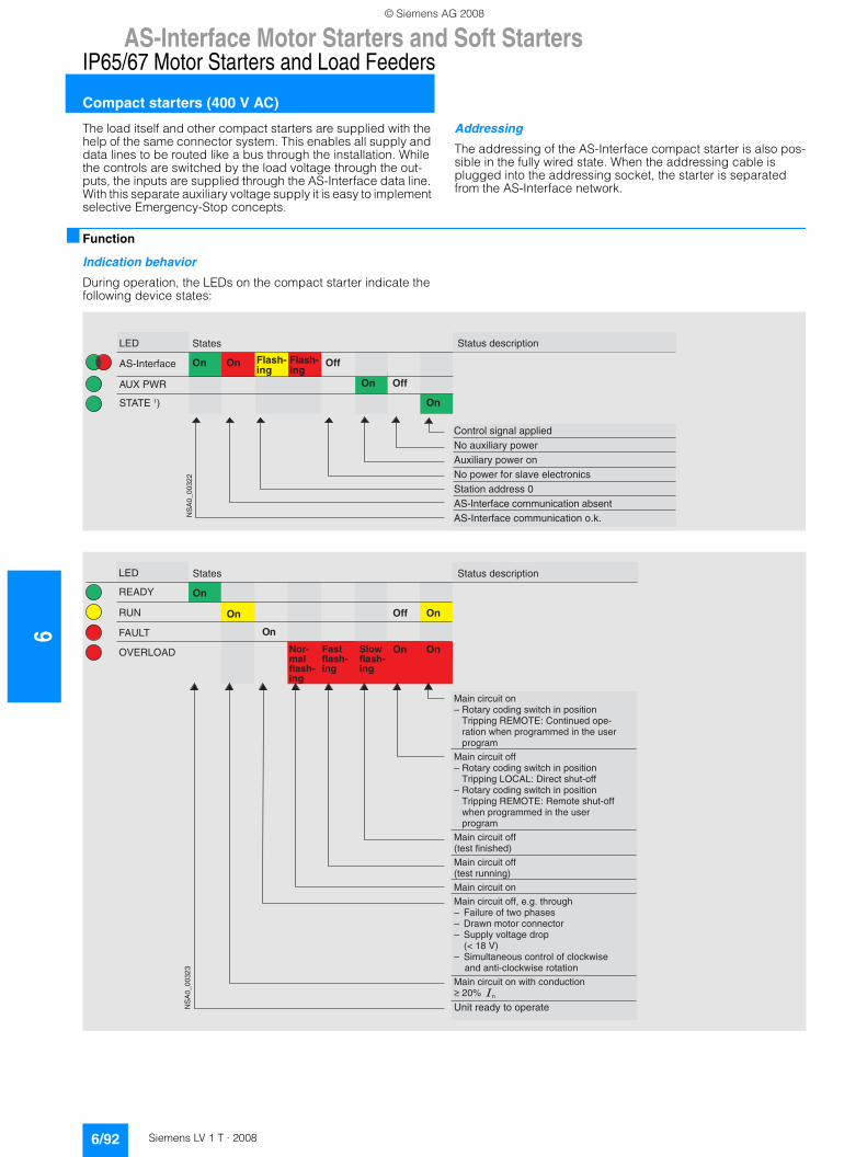
6AS-Interface Motor Starters and Soft Starters
IP65/67 Motor Starters and Load Feeders
Compact starters (400 V AC)
6/92 Siemens LV 1 T · 2008
The load itself and other compact starters are supplied with the help of the same connector system. This enables all supply and data lines to be routed like a bus through the installation. While the controls are switched by the load voltage through the out-puts, the inputs are supplied through the AS-Interface data line. With this separate auxiliary voltage supply it is easy to implement selective Emergency-Stop concepts.
Addressing
The addressing of the AS-Interface compact starter is also pos-sible in the fully wired state. When the addressing cable is plugged into the addressing socket, the starter is separated from the AS-Interface network.
■ Function
Indication behavior
During operation, the LEDs on the compact starter indicate the following device states:
) *
+,-�%./
+��0�����#�
�'+' ��1
��+�����
���������#�������
&�����!���"�!���!���������!���������+���!��������������������������!$���!�#�����#����������������+��0�����#��#������#����� ����+��0�����#��#������#������2(2
��
�����
�������
�� �� �������
���
�� ���
) *
/,�
/ +*3
4+,)'
��+������
56 /)5+*
����� ���������#�������
7���#��#������8�/�����#����"�����#����������������'������"�/ 75' 9�&������������������������������"�����������������������"��7���#��#�������8�/�����#����"�����#����������������'������"�)5&+)9�*���#����������8�/�����#����"�����#����������������'������"�/ 75' 9�/�������������������������"�����������������������"��7���#��#�������:�������������17���#��#�������:�����������"17���#��#������7���#��#�������;��2"2������"�8 4�!����������������8 *����������#����#���8 ����!��$�!�"������:<��=�61
8 ����!�������#�����!����#!�#(���������������#!�#(������������7���#��#������������#����#����>���?�����,������������������
��
�� ��� ��
��
� ������������
�����������
�� ��������
�� ��
© Siemens AG 2008
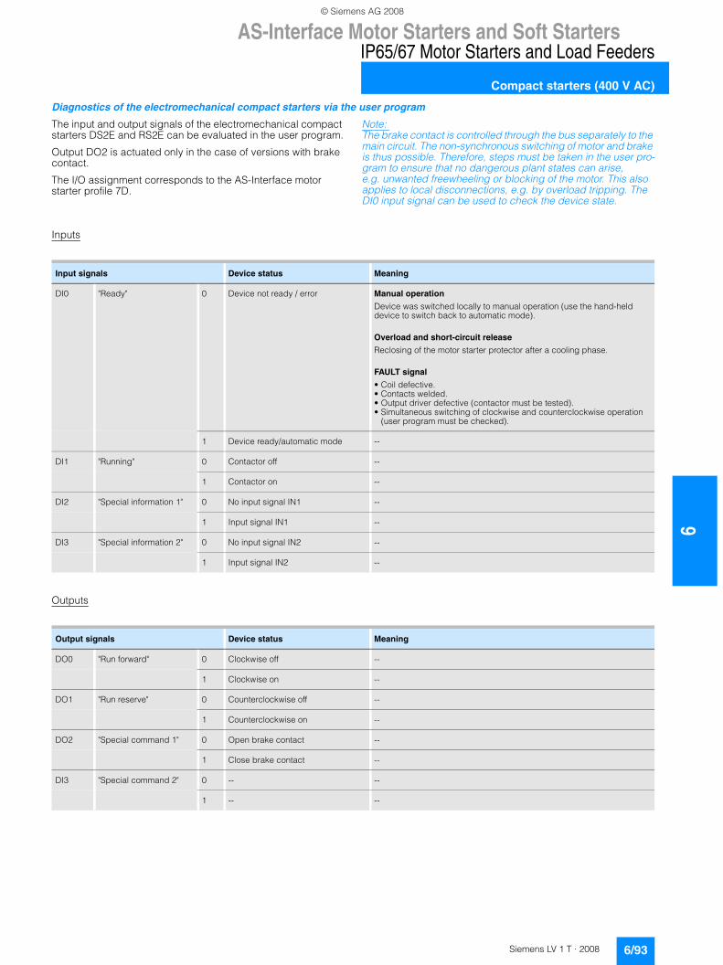
AS-Interface Motor Starters and Soft Starters
6/93Siemens LV 1 T · 2008
6
IP65/67 Motor Starters and Load Feeders
Compact starters (400 V AC)
Diagnostics of the electromechanical compact starters via the user program
The input and output signals of the electromechanical compact starters DS2E and RS2E can be evaluated in the user program.
Output DO2 is actuated only in the case of versions with brake contact.
The I/O assignment corresponds to the AS-Interface motor starter profile 7D.
Note: The brake contact is controlled through the bus separately to the main circuit. The non-synchronous switching of motor and brake is thus possible. Therefore, steps must be taken in the user pro-gram to ensure that no dangerous plant states can arise, e.g. unwanted freewheeling or blocking of the motor. This also applies to local disconnections, e.g. by overload tripping. The DI0 input signal can be used to check the device state.
Inputs
Outputs
Input signals Device status Meaning
DI0 "Ready" 0 Device not ready / error Manual operation
Device was switched locally to manual operation (use the hand-held device to switch back to automatic mode).
Overload and short-circuit release
Reclosing of the motor starter protector after a cooling phase.
FAULT signal
• Coil defective.• Contacts welded.• Output driver defective (contactor must be tested).• Simultaneous switching of clockwise and counterclockwise operation
(user program must be checked).
1 Device ready/automatic mode --
DI1 "Running" 0 Contactor off --
1 Contactor on --
DI2 "Special information 1" 0 No input signal IN1 --
1 Input signal IN1 --
DI3 "Special information 2" 0 No input signal IN2 --
1 Input signal IN2 --
Output signals Device status Meaning
DO0 "Run forward" 0 Clockwise off --
1 Clockwise on --
DO1 "Run reserve" 0 Counterclockwise off --
1 Counterclockwise on --
DO2 "Special command 1" 0 Open brake contact --
1 Close brake contact --
DI3 "Special command 2" 0 -- --
1 -- --
© Siemens AG 2008
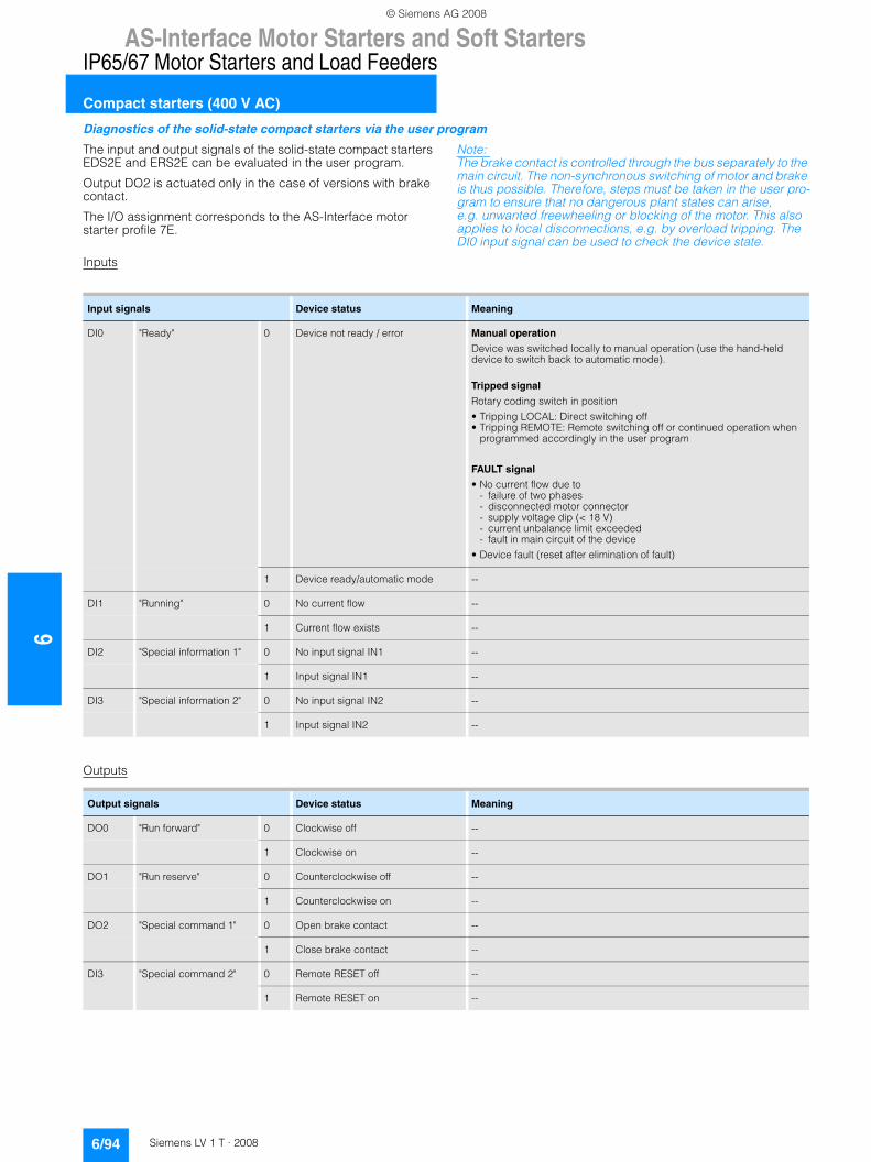
6AS-Interface Motor Starters and Soft Starters
IP65/67 Motor Starters and Load Feeders
Compact starters (400 V AC)
6/94 Siemens LV 1 T · 2008
Diagnostics of the solid-state compact starters via the user program
The input and output signals of the solid-state compact starters EDS2E and ERS2E can be evaluated in the user program.
Output DO2 is actuated only in the case of versions with brake contact.
The I/O assignment corresponds to the AS-Interface motor starter profile 7E.
Note: The brake contact is controlled through the bus separately to the main circuit. The non-synchronous switching of motor and brake is thus possible. Therefore, steps must be taken in the user pro-gram to ensure that no dangerous plant states can arise, e.g. unwanted freewheeling or blocking of the motor. This also applies to local disconnections, e.g. by overload tripping. The DI0 input signal can be used to check the device state.
Inputs
Outputs
Input signals Device status Meaning
DI0 "Ready" 0 Device not ready / error Manual operation
Device was switched locally to manual operation (use the hand-held device to switch back to automatic mode).
Tripped signal
Rotary coding switch in position
• Tripping LOCAL: Direct switching off• Tripping REMOTE: Remote switching off or continued operation when
programmed accordingly in the user program
FAULT signal
• No current flow due to- failure of two phases- disconnected motor connector- supply voltage dip (< 18 V)- current unbalance limit exceeded- fault in main circuit of the device
• Device fault (reset after elimination of fault)
1 Device ready/automatic mode --
DI1 "Running" 0 No current flow --
1 Current flow exists --
DI2 "Special information 1" 0 No input signal IN1 --
1 Input signal IN1 --
DI3 "Special information 2" 0 No input signal IN2 --
1 Input signal IN2 --
Output signals Device status Meaning
DO0 "Run forward" 0 Clockwise off --
1 Clockwise on --
DO1 "Run reserve" 0 Counterclockwise off --
1 Counterclockwise on --
DO2 "Special command 1" 0 Open brake contact --
1 Close brake contact --
DI3 "Special command 2" 0 Remote RESET off --
1 Remote RESET on --
© Siemens AG 2008
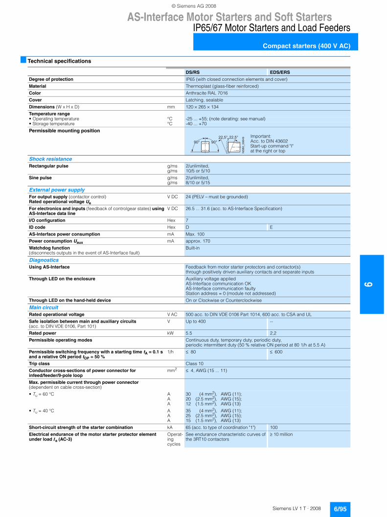
AS-Interface Motor Starters and Soft Starters
6/95Siemens LV 1 T · 2008
6
IP65/67 Motor Starters and Load Feeders
Compact starters (400 V AC)
■ Technical specifications
DS/RS EDS/ERS
Degree of protection IP65 (with closed connection elements and cover)
Material Thermoplast (glass-fiber reinforced)
Color Anthracite RAL 7016
Cover Latching, sealable
Dimensions (W x H x D) mm 120 × 265 × 134
Temperature range• Operating temperature °C -25 ... +55; (note derating: see manual)• Storage temperature °C -40 ... +70
Permissible mounting position
Shock resistance Rectangular pulse g/ms
g/ms2/unlimited, 10/5 or 5/10
Sine pulse g/msg/ms
2/unlimited, 8/10 or 5/15
External power supply For output supply (contactor control) Rated operational voltage Ue
V DC 24 (PELV – must be grounded)
For electronics and inputs (feedback of controlgear states) using AS-Interface data line
V DC 26.5 ... 31.6 (acc. to AS-Interface Specification)
I/O configuration Hex 7
ID code Hex D E
AS-Interface power consumption mA Max. 100
Power consumption Uaux mA approx. 170
Watchdog function (disconnects outputs in the event of AS-Interface fault)
Built-in
Diagnostics Using AS-Interface Feedback from motor starter protectors and contactor(s)
through positively driven auxiliary contacts and separate inputs
Through LED on the enclosure Auxiliary voltage appliedAS-Interface communication OKAS-Interface communication faultyStation address = 0 (module not addressed)
Through LED on the hand-held device On or Clockwise or Counterclockwise
Main circuit Rated operational voltage V AC 500 acc. to DIN VDE 0106 Part 1014, 600 acc. to CSA and UL
Safe isolation between main and auxiliary circuits (acc. to DIN VDE 0106, Part 101)
V Up to 400 --
Rated power kW 5.5 2,2
Permissible operating modes Continuous duty, temporary duty, periodic duty, periodic intermittent duty (50 % relative ON period at 80 1/h at 5.5 A)
Permissible switching frequency with a starting time tA = 0.1 s and a relative ON period tOP = 50 %
1/h ≤ 80 ≤ 600
Trip class Class 10
Conductor cross-sections of power connector for infeed/feeder/9-pole loop
mm2 ≤ 4, AWG (15 ... 11)
Max. permissible current through power connector (dependent on cable cross-section)
• Tu = 60 °C AAA
30 (4 mm2), AWG (11);20 (2.5 mm2), AWG (15);12 (1.5 mm2), AWG (13)
• Tu = 40 °C AAA
35 (4 mm2), AWG (11);25 (2.5 mm2), AWG (15);15 (1.5 mm2), AWG (13)
Short-circuit strength of the starter combination kA 65 (acc. to type of coordination "1") 100
Electrical endurance of the motor starter protector element under load Ia (AC-3)
Operat-ing cycles
See endurance characteristic curves of the 3RT10 contactors
≥ 10 million
���������� � � � �
� � �� � �
Important:Acc. to DIN 43602 Start-up command "I" at the right or top
© Siemens AG 2008
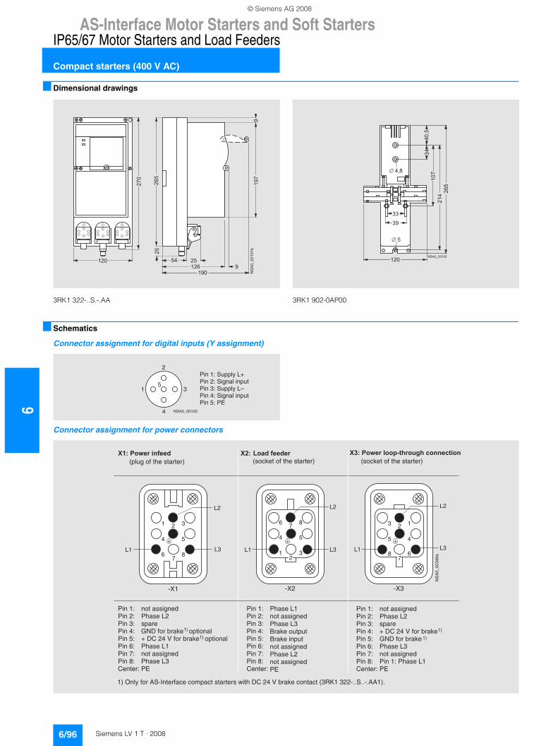
6AS-Interface Motor Starters and Soft Starters
IP65/67 Motor Starters and Load Feeders
Compact starters (400 V AC)
6/96 Siemens LV 1 T · 2008
■ Dimensional drawings
3RK1 322-..S.-.AA 3RK1 902-0AP00
■ Schematics
Connector assignment for digital inputs (Y assignment)
Connector assignment for power connectors
�� ��������
��
� ����
�
��
� �
� �
�
�
� � �
�
� � � � � � � �
���
���
��
� �
��
��
� �
� �
� � � �
� � �
NSA0_00100
3
2
4
15
Pin 1: Supply L+Pin 2: Signal inputPin 3: Supply L–Pin 4: Signal inputPin 5: PE
6
1
4
8
3
5
2
7
L2
L3L1
-X2
6
1
4
8
3
5
2
7
L2
L1 L3
-X1
8
3
5
6
1
4
2
7
L2
L3L1
-X3
NS
A0_
0034
9a
Pin 1:Pin 2:Pin 3:Pin 4:Pin 5:Pin 6:Pin 7:Pin 8:Center:
not assignedPhase L2spareGND for brake optional+ DC 24 V for brake optionalPhase L1not assignedPhase L3PE
not assignedPhase L2spare+ DC 24 V for brake GND for brakePhase L3not assignedPin 1: Phase L1PE
1) Only for AS-Interface compact starters with DC 24 V brake contact (3RK1 322-..S..-.AA1).
Pin 1:Pin 2:Pin 3:Pin 4:Pin 5:Pin 6:Pin 7:Pin 8:Center:
1)
1)
1)
1)
� � �� � � � � � � � � � �
(plug of the starter)� � � � � �
(socket of the starter)� � � � � � � � � � � � � � � � � � � � � � � � � � � � �
(socket of the starter)
Pin 1:Pin 2:Pin 3:Pin 4:Pin 5:Pin 6:Pin 7:Pin 8:Center:
Phase L1not assignedPhase L3Brake outputBrake inputnot assignedPhase L2not assignedPE
© Siemens AG 2008
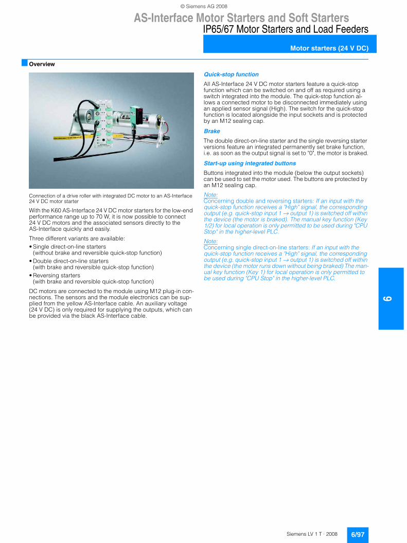
AS-Interface Motor Starters and Soft Starters
6/97Siemens LV 1 T · 2008
6
IP65/67 Motor Starters and Load Feeders
Motor starters (24 V DC)
■ Overview
Connection of a drive roller with integrated DC motor to an AS-Interface 24 V DC motor starter
With the K60 AS-Interface 24 V DC motor starters for the low-end performance range up to 70 W, it is now possible to connect 24 V DC motors and the associated sensors directly to the AS-Interface quickly and easily.
Three different variants are available:• Single direct-on-line starters
(without brake and reversible quick-stop function)• Double direct-on-line starters
(with brake and reversible quick-stop function)• Reversing starters
(with brake and reversible quick-stop function)
DC motors are connected to the module using M12 plug-in con-nections. The sensors and the module electronics can be sup-plied from the yellow AS-Interface cable. An auxiliary voltage (24 V DC) is only required for supplying the outputs, which can be provided via the black AS-Interface cable.
Quick-stop function
All AS-Interface 24 V DC motor starters feature a quick-stop function which can be switched on and off as required using a switch integrated into the module. The quick-stop function al-lows a connected motor to be disconnected immediately using an applied sensor signal (High). The switch for the quick-stop function is located alongside the input sockets and is protected by an M12 sealing cap.
Brake
The double direct-on-line starter and the single reversing starter versions feature an integrated permanently set brake function, i.e. as soon as the output signal is set to "0", the motor is braked.
Start-up using integrated buttons
Buttons integrated into the module (below the output sockets) can be used to set the motor used. The buttons are protected by an M12 sealing cap.
Note: Concerning double and reversing starters: If an input with the quick-stop function receives a "High" signal, the corresponding output (e.g. quick-stop input 1 → output 1) is switched off within the device (the motor is braked). The manual key function (Key 1/2) for local operation is only permitted to be used during "CPU Stop" in the higher-level PLC.
Note:Concerning single direct-on-line starters: If an input with the quick-stop function receives a "High" signal, the corresponding output (e.g. quick-stop input 1 → output 1) is switched off within the device (the motor runs down without being braked) The man-ual key function (Key 1) for local operation is only permitted to be used during "CPU Stop" in the higher-level PLC.
© Siemens AG 2008
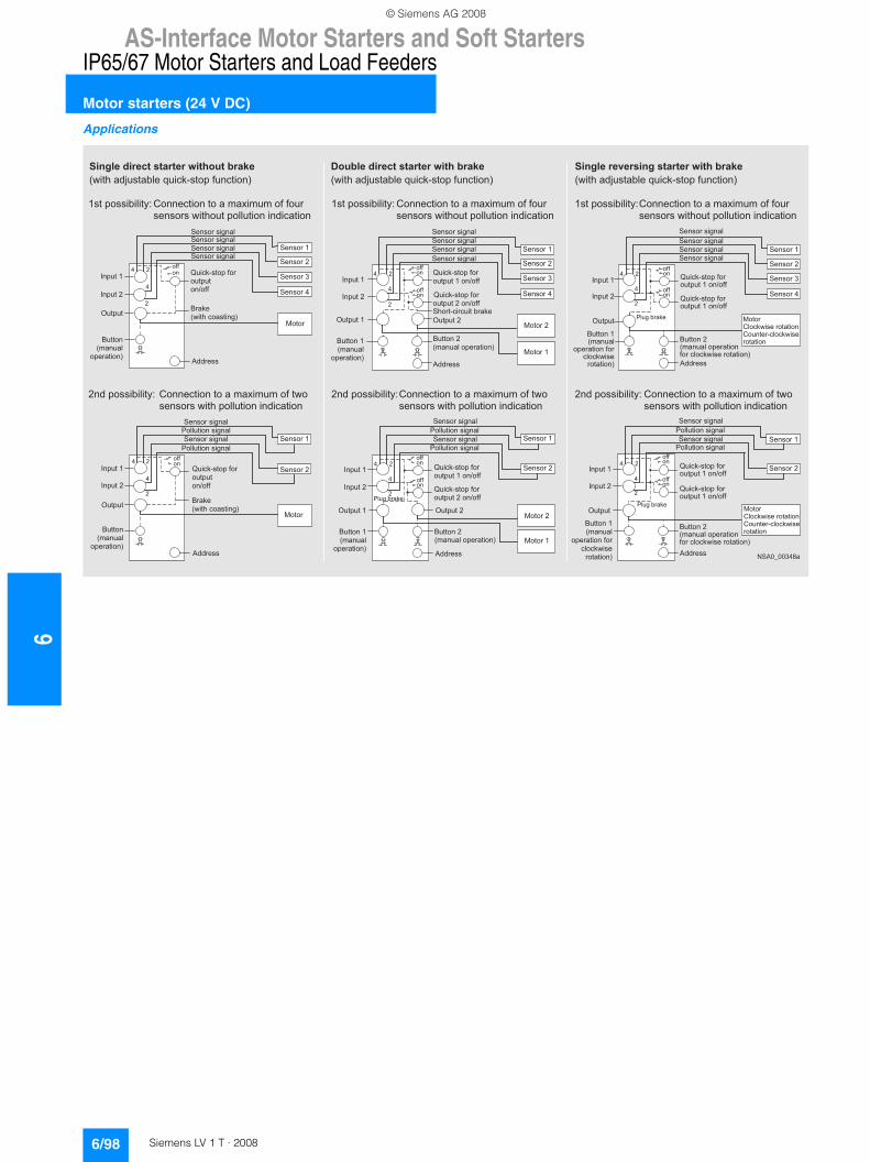
6AS-Interface Motor Starters and Soft Starters
IP65/67 Motor Starters and Load Feeders
Motor starters (24 V DC)
6/98 Siemens LV 1 T · 2008
Applications
�
�
�
�
�
�
�
�
�
�
�
�
� � � � � � � � � �
� � � � � � �
� � � � � �
� � � � � � �
� � � � � � �
� � � � � � � �
� � � � � ! � � "
# � ! $ % & ' � � � � ( �
� � � � � �
� � ) � ( (
* * � ' '
� � � ' � � �
� � � ' � �
� � � ' � � �
� � � ' � � �
+ � � �
� � � ' � � ' ! , � � �
� � � ' � � ' ! , � � �
� � � ' � � ' ! , � � �
� � � ' � � ' ! , � � �
� ( (
� �
� � % �
� - ! � . � $ � � ' � ! � , "
� � � � � � �
� � � � � �
� � � � � �
� � � � � �
� � � � � � �
� � � � � ! � � "
# � ! $ % & ' � � � � ( �
� � � � � �
� � ) � ( (
* * � ' '
� � � ' � � �
� � � ' � �
/ � � � � � ! � � � ' ! , � � �
� � � ' � � ' ! , � � �
� � � ' � � ' ! , � � �
/ � � � � � ! � � � ' ! , � � �
+ � � �
� � % �
� - ! � . � $ � � ' � ! � , "
� ( (� �
� � � � � � �
� � � � � �
� � � � � � � �
� � � � � � � �
� � � � � � �
� � � � � ! � � "
� � � � � � �
# � ! $ % & ' � � � � ( �
� � � � � � � � � � ) � ( (
# � ! $ % & ' � � � � ( �
� � � � � � � � � � � ) � ( (
� � � � � � �
� � � � � � � � � � � � � ! � � "
* * � ' '
� � � ' � � �
� � � ' � �
� � � ' � � �
� � � ' � � �
� � � ' � � ' ! , � � �
� � � ' � � ' ! , � � �
� � � ' � � ' ! , � � �
� � � ' � � ' ! , � � �
� ( (� �
� ( (� �
+ � � � �
+ � � � � �
� . � � & $ ! $ � ! � � � � % �
� � � � � � �
� � � � � �
� � � � � � � �
# � ! $ % & ' � � � � ( �
� � � � � � � � � � � ) � ( (
* * � ' '
� � � ' � � �
� � � ' � �
+ � � � �
/ � � � � � ! � � � ' ! , � � �
� � � ' � � ' ! , � � �
� � � ' � � ' ! , � � �
� ( (� �
� ( (� �
# � ! $ % & ' � � � � ( �
� � � � � � � � � � ) � ( (/ � � , � � � % �
/ � � � � � ! � � � ' ! , � � �
� � � � � � �
� � � � � � � � � � � � � ! � � "
� � � � � � �
+ � � � � �
� � � � � � �
� � � � � �
� � � � � �
# � ! $ % & ' � � � � ( �
� � � � � � � � � � � ) � ( (
* * � ' '
� � � ' � � �
� � � ' � �
� � � ' � � �
� � � ' � � �
+ � � �
0 � � $ % - ! ' � � � � � � ! � �
0 � � � � � & $ � � $ % - ! ' �
� � � � ! � �
� � � ' � � ' ! , � � �
� � � ' � � ' ! , � � �
� � � ' � � ' ! , � � �
� � � ' � � ' ! , � � �
� ( (� �
� ( (� �
# � ! $ % & ' � � � � ( �
� � � � � � � � � � � ) � ( (
/ � � , � � � % �
� � � � � � �
� � � � � �
� � � � � � �
# � ! $ % & ' � � � � ( �
� � � � � � � � � � � ) � ( (
* * � ' '
� � � ' � � �
� � � ' � �
+ � � �
0 � � $ % - ! ' � � � � � � ! � �
0 � � � � � & $ � � $ % - ! ' �
� � � � ! � �
� � � ' � � ' ! , � � �
� � � ' � � ' ! , � � �
� ( (� �
� ( (� �
# � ! $ % & ' � � � � ( �
� � � � � � � � � � � ) � ( (
/ � � , � � � % �
/ � � � � � ! � � � ' ! , � � �
/ � � � � � ! � � � ' ! , � � �
� � � � � � � �
� � � � � � �
� � � � � ! � � � ( �
$ � � $ % - ! ' �
� � � � ! � � "
� � � � � � �
� � � � � � � � � � � � � ! � �
( � � $ � � $ % - ! ' � � � � � � ! � � "
� � � � � � �
� � � � � � � � � � � � � ! � �
( � � $ � � $ % - ! ' � � � � � � ! � � "
� � � � � � � �
� � � � � � �
� � � � � ! � � � ( �
$ � � $ % - ! ' �
� � � � ! � � "
� � � � � � � �
� � � � � � �
� � � � � ! � � "
� - ! � . � � * 1 � ' � � � � � � 2 � ! $ % & ' � � � � ( � � $ � ! � � "
� ' � � � � ' ' ! � ! � ! � 3 4 0 � � � � $ � ! � � � � � � � � � � 5 ! � � � � � ( � ( � �
' � � ' � ' � - ! � . � � � � � � � � � � ! � � � ! � * ! $ � � ! � �
� � � � � � � � � � � � � � � � � � � � � � � � � � �
� - ! � . � � * 1 � ' � � � � � � 2 � ! $ % & ' � � � � ( � � $ � ! � � "
� � � � � � � � � � � � � � � � � � � � � � � �
� ' � � � � ' ' ! � ! � ! � 3 4 0 � � � � $ � ! � � � � � � � � � � 5 ! � � � � � ( � ( � �
' � � ' � ' � - ! � . � � � � � � � � � � ! � � � ! � * ! $ � � ! � �
� - ! � . � � * 1 � ' � � � � � � 2 � ! $ % & ' � � � � ( � � $ � ! � � "
� � � � � � � � � � � � � � � � � � � � � � � � �
0 � � � � $ � ! � � � � � � � � � � 5 ! � � � � � ( � ( � �
' � � ' � ' � - ! � . � � � � � � � � � � ! � � � ! � * ! $ � � ! � �
� ' � � � � ' ' ! � ! � ! � 3 4
� * � � � ' ' ! � ! � ! � 3 4 0 � � � � $ � ! � � � � � � � � � � 5 ! � � � � � ( � � - �
' � � ' � ' � - ! � . � � � � � � � ! � � � ! � * ! $ � � ! � �
� * � � � ' ' ! � ! � ! � 3 4 0 � � � � $ � ! � � � � � � � � � � 5 ! � � � � � ( � � - �
' � � ' � ' � - ! � . � � � � � � � ! � � � ! � * ! $ � � ! � �
0 � � � � $ � ! � � � � � � � � � � 5 ! � � � � � ( � � - �
' � � ' � ' � - ! � . � � � � � � � ! � � � ! � * ! $ � � ! � �
� * � � � ' ' ! � ! � ! � 3 4
© Siemens AG 2008
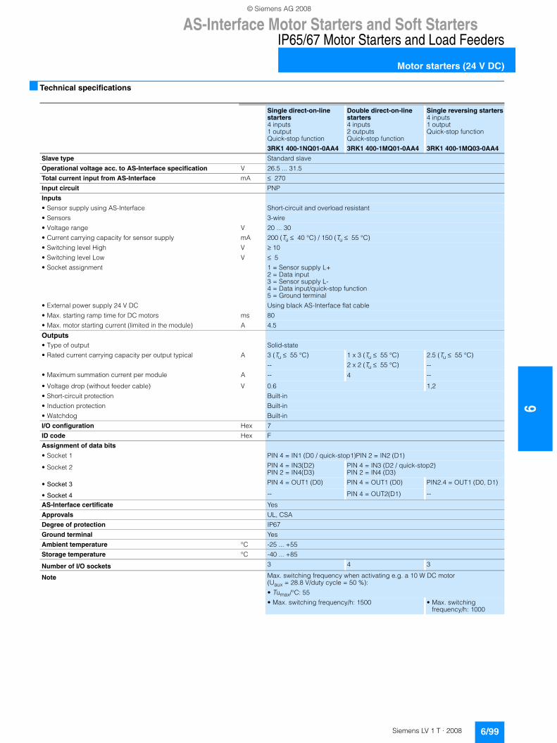
AS-Interface Motor Starters and Soft Starters
6/99Siemens LV 1 T · 2008
6
IP65/67 Motor Starters and Load Feeders
Motor starters (24 V DC)
■ Technical specifications
Single direct-on-line starters4 inputs1 outputQuick-stop function
3RK1 400-1NQ01-0AA4
Double direct-on-line starters4 inputs2 outputsQuick-stop function
3RK1 400-1MQ01-0AA4
Single reversing starters4 inputs1 outputQuick-stop function
3RK1 400-1MQ03-0AA4
Slave type Standard slave
Operational voltage acc. to AS-Interface specification V 26.5 ... 31.5
Total current input from AS-Interface mA ≤ 270
Input circuit PNP
Inputs
• Sensor supply using AS-Interface Short-circuit and overload resistant
• Sensors 3-wire
• Voltage range V 20 ... 30
• Current carrying capacity for sensor supply mA 200 (Tu ≤ 40 °C) / 150 (Tu ≤ 55 °C)
• Switching level High V ≥ 10
• Switching level Low V ≤ 5
• Socket assignment 1 = Sensor supply L+2 = Data input3 = Sensor supply L-4 = Data input/quick-stop function5 = Ground terminal
• External power supply 24 V DC Using black AS-Interface flat cable
• Max. starting ramp time for DC motors ms 80
• Max. motor starting current (limited in the module) A 4.5
Outputs
• Type of output Solid-state
• Rated current carrying capacity per output typical A 3 (Tu ≤ 55 °C)
--
1 x 3 (Tu ≤ 55 °C)
2 x 2 (Tu ≤ 55 °C)
2.5 (Tu ≤ 55 °C)
--
• Maximum summation current per module A -- 4 --
• Voltage drop (without feeder cable) V 0.6 1,2
• Short-circuit protection Built-in
• Induction protection Built-in
• Watchdog Built-in
I/O configuration Hex 7
ID code Hex F
Assignment of data bits
• Socket 1 PIN 4 = IN1 (D0 / quick-stop1)PIN 2 = IN2 (D1)
• Socket 2 PIN 4 = IN3(D2)PIN 2 = IN4(D3)
PIN 4 = IN3 (D2 / quick-stop2)PIN 2 = IN4 (D3)
• Socket 3 PIN 4 = OUT1 (D0) PIN 4 = OUT1 (D0) PIN2.4 = OUT1 (D0, D1)
• Socket 4 -- PIN 4 = OUT2(D1) --
AS-Interface certificate Yes
Approvals UL, CSA
Degree of protection IP67
Ground terminal Yes
Ambient temperature °C -25 ... +55
Storage temperature °C -40 ... +85
Number of I/O sockets 3 4 3
Note Max. switching frequency when activating e.g. a 10 W DC motor (Uaux = 28.8 V/duty cycle = 50 %):
• Tumax/°C: 55
• Max. switching frequency/h: 1500 • Max. switching frequency/h: 1000
© Siemens AG 2008
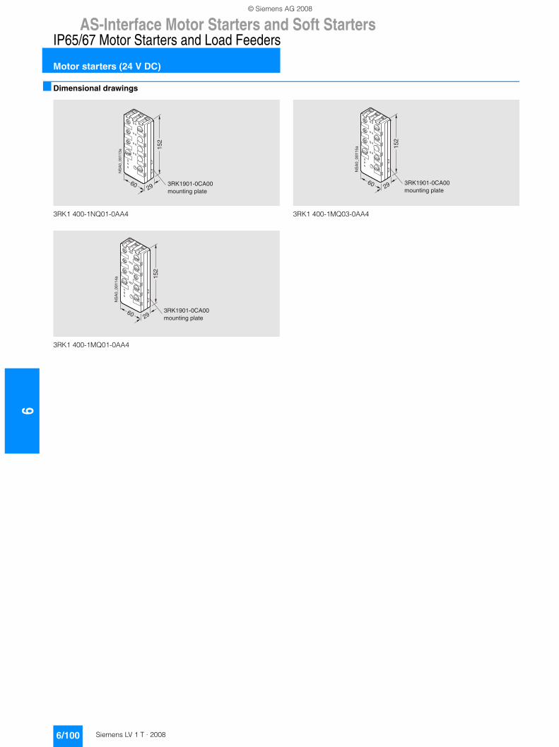
6AS-Interface Motor Starters and Soft Starters
IP65/67 Motor Starters and Load Feeders
Motor starters (24 V DC)
6/100 Siemens LV 1 T · 2008
■ Dimensional drawings
3RK1 400-1NQ01-0AA4
3RK1 400-1MQ01-0AA4
3RK1 400-1MQ03-0AA4
@
��+�������
��
�� �/A�@����&+���������"��!��
@
��+������� ��
�� �/A�@����&+���������"��!��
@
��+������� ��
�� �/A�@����&+���������"��!��
© Siemens AG 2008
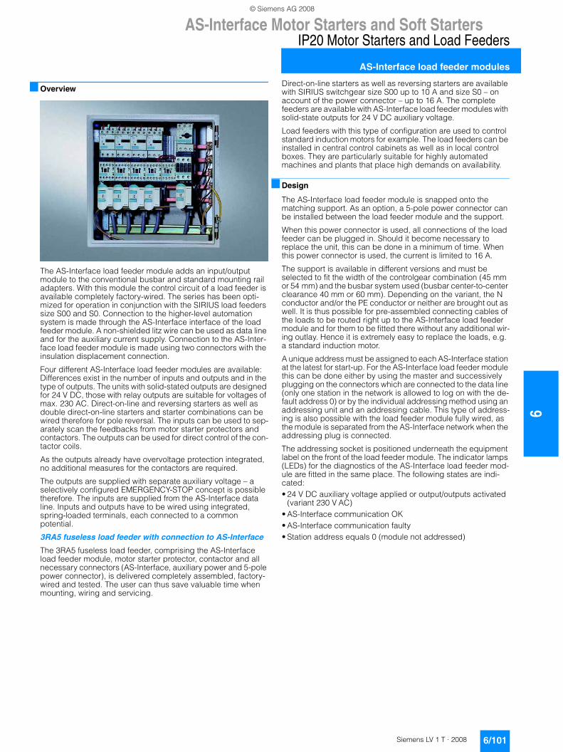
AS-Interface Motor Starters and Soft Starters
6/101Siemens LV 1 T · 2008
6
IP20 Motor Starters and Load Feeders
AS-Interface load feeder modules
■ Overview
The AS-Interface load feeder module adds an input/output module to the conventional busbar and standard mounting rail adapters. With this module the control circuit of a load feeder is available completely factory-wired. The series has been opti-mized for operation in conjunction with the SIRIUS load feeders size S00 and S0. Connection to the higher-level automation system is made through the AS-Interface interface of the load feeder module. A non-shielded litz wire can be used as data line and for the auxiliary current supply. Connection to the AS-Inter-face load feeder module is made using two connectors with the insulation displacement connection.
Four different AS-Interface load feeder modules are available: Differences exist in the number of inputs and outputs and in the type of outputs. The units with solid-stated outputs are designed for 24 V DC, those with relay outputs are suitable for voltages of max. 230 AC. Direct-on-line and reversing starters as well as double direct-on-line starters and starter combinations can be wired therefore for pole reversal. The inputs can be used to sep-arately scan the feedbacks from motor starter protectors and contactors. The outputs can be used for direct control of the con-tactor coils.
As the outputs already have overvoltage protection integrated, no additional measures for the contactors are required.
The outputs are supplied with separate auxiliary voltage – a selectively configured EMERGENCY-STOP concept is possible therefore. The inputs are supplied from the AS-Interface data line. Inputs and outputs have to be wired using integrated, spring-loaded terminals, each connected to a common potential.
3RA5 fuseless load feeder with connection to AS-Interface
The 3RA5 fuseless load feeder, comprising the AS-Interface load feeder module, motor starter protector, contactor and all necessary connectors (AS-Interface, auxiliary power and 5-pole power connector), is delivered completely assembled, factory-wired and tested. The user can thus save valuable time when mounting, wiring and servicing.
Direct-on-line starters as well as reversing starters are available with SIRIUS switchgear size S00 up to 10 A and size S0 – on account of the power connector – up to 16 A. The complete feeders are available with AS-Interface load feeder modules with solid-state outputs for 24 V DC auxiliary voltage.
Load feeders with this type of configuration are used to control standard induction motors for example. The load feeders can be installed in central control cabinets as well as in local control boxes. They are particularly suitable for highly automated machines and plants that place high demands on availability.
■ Design
The AS-Interface load feeder module is snapped onto the matching support. As an option, a 5-pole power connector can be installed between the load feeder module and the support.
When this power connector is used, all connections of the load feeder can be plugged in. Should it become necessary to replace the unit, this can be done in a minimum of time. When this power connector is used, the current is limited to 16 A.
The support is available in different versions and must be selected to fit the width of the controlgear combination (45 mm or 54 mm) and the busbar system used (busbar center-to-center clearance 40 mm or 60 mm). Depending on the variant, the N conductor and/or the PE conductor or neither are brought out as well. It is thus possible for pre-assembled connecting cables of the loads to be routed right up to the AS-Interface load feeder module and for them to be fitted there without any additional wir-ing outlay. Hence it is extremely easy to replace the loads, e.g. a standard induction motor.
A unique address must be assigned to each AS-Interface station at the latest for start-up. For the AS-Interface load feeder module this can be done either by using the master and successively plugging on the connectors which are connected to the data line (only one station in the network is allowed to log on with the de-fault address 0) or by the individual addressing method using an addressing unit and an addressing cable. This type of address-ing is also possible with the load feeder module fully wired, as the module is separated from the AS-Interface network when the addressing plug is connected.
The addressing socket is positioned underneath the equipment label on the front of the load feeder module. The indicator lamps (LEDs) for the diagnostics of the AS-Interface load feeder mod-ule are fitted in the same place. The following states are indi-cated:• 24 V DC auxiliary voltage applied or output/outputs activated
(variant 230 V AC)• AS-Interface communication OK• AS-Interface communication faulty• Station address equals 0 (module not addressed)
© Siemens AG 2008
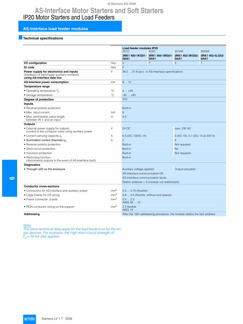
6AS-Interface Motor Starters and Soft Starters
IP20 Motor Starters and Load Feeders
AS-Interface load feeder modules
6/102 Siemens LV 1 T · 2008
■ Technical specifications
Note:The same technical data apply for the load feeders as for the sin-gle devices. For example, the high short-circuit strength of Iq = 50 kA also applies.
Load feeder modules IP202I/1O
3RK1 400-1KG01-0AA1
4I/2O
3RK1 400-1MG01-0AA1
2I/1AR
3RK1 402-3KG02-0AA1
3I/2AR
3RK1 402-3LG02-0AA1
I/O configuration Hex 3 7 3 7
ID code Hex F
Power supply for electronics and inputs(feedback of switchgear auxiliary contacts) using AS-Interface data line
V 26.5 ... 31.6 (acc. to AS-Interface specification)
AS-Interface power consumption mA 8 ... 12
Temperature range
• Operating temperature Tu °C 0 ... +55
• Storage temperature °C -40 ... +85
Degree of protection IP20
Inputs
• Reverse polarity protection Built-in
• Max. input current mA 6
• Max. permissible cable length between IN + and an input
m 0.4
Outputs
• External power supply for outputs(control of the contactor coils) using auxiliary power
V 24 DC max. 230 AC
• Current carrying capacity Ie A 0.5 (DC-13/DC-14) 3 (AC-15); 0.1 (DC-13 at 220 V)
• Summation current (thermal) Ith A 2 3
• Reverse polarity protection Built-in Not required
• Short-circuit protection Built-in No
• Induction protection Built-in Not required
• Watchdog function (disconnects outputs in the event of AS-Interface fault)
Built-in
Diagnostics
• Through LED on the enclosure Auxiliary voltage applied Output actuated
AS-Interface communication OK
AS-Interface communication faulty
Station address = 0 (module not addressed)
Conductor cross-sections
• Connectors for AS-Interface and auxiliary power mm2 0.5 ... 0.75 (flexible)
• Cage Clamp for I/O wiring mm2 0.8 ... 2.5 (flexible, without end sleeve)
• Power connector, 5-pole mm2 0.5 ... 2.5AWG 28 ... 12
• PE/N conductor wiring on the support mm2 2.5 flexible AWG 13
Addressing After the 15th addressing procedure, the module retains the last address
© Siemens AG 2008
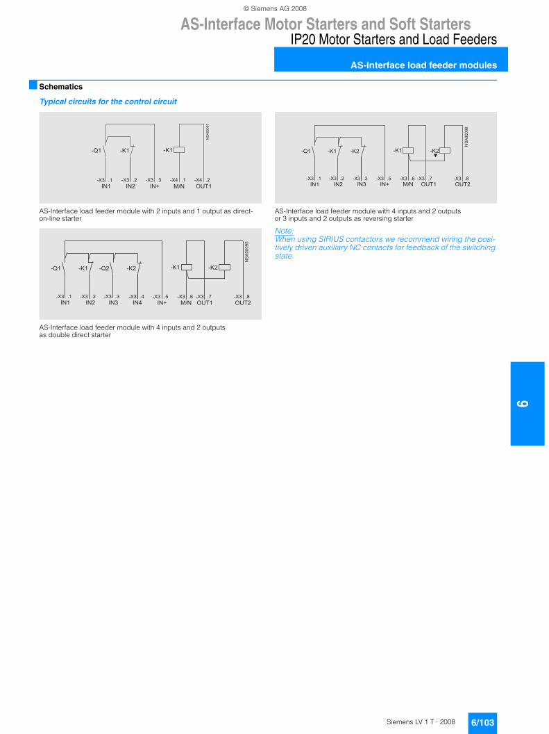
AS-Interface Motor Starters and Soft Starters
6/103Siemens LV 1 T · 2008
6
IP20 Motor Starters and Load Feeders
AS-Interface load feeder modules
■ Schematics
Typical circuits for the control circuit
AS-Interface load feeder module with 2 inputs and 1 output as direct-on-line starter
AS-Interface load feeder module with 4 inputs and 2 outputs as double direct starter
AS-Interface load feeder module with 4 inputs and 2 outputs or 3 inputs and 2 outputs as reversing starter
Note:When using SIRIUS contactors we recommend wiring the posi-tively driven auxiliary NC contacts for feedback of the switching state.
� � �
�� �����
� � + ) �
& 6 � � 7 � & 6 � � 7 & 6 � � 7 � & 6 � � 7 � & 6 � � 7
� � 8 � 9 : �
& # � & ; � & ; �
�� �����
� � � + ) �
& 6 � � 7 � & 6 � � 7 � & 6 � � 7 � & 6 � � 7 � & 6 � � 7 �& 6 � � 7 & 6 � � 7 �
� � �� � � � �
& 6 � � 7 �
� � 8 � 9 : � � 9 :
& # � & ; � & # & ; & ; � & ;
�� �����
� � � + ) �
& 6 � � 7 & 6 � � 7 � & 6 � � 7 � & 6 � � 7 � & 6 � � 7 �
� � � � �
& 6 � � 7 � & 6 � � 7 �
� � 8 � 9 : � � 9 :
& # � & ; � & ; & ; � & ;
© Siemens AG 2008
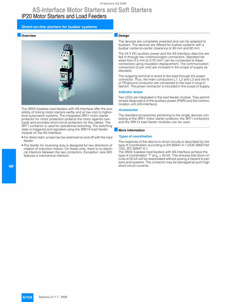
6AS-Interface Motor Starters and Soft Starters
IP20 Motor Starters and Load Feeders
Direct-on-line starters for busbar systems
6/104 Siemens LV 1 T · 2008
■ Overview
The 3RA5 fuseless load feeders with AS-Interface offer the pos-sibility of linking motor starters swiftly and at low cost to higher-level automation systems. The integrated 3RV1 motor starter protector for motor protection protects the motor against over-loads and provides short-circuit protection for the cables. The 3RT1 contactor is used for operational switching. The switching state is triggered and signaled using the 3RK14 load feeder module on the AS-Interface.• For direct start, a load can be switched on and off with the load
feeder.• The feeder for reversing duty is designed for two directions of
rotation of induction motors. On these units, there is no electri-cal interlock between the two contactors. Exception: size S00 features a mechanical interlock.
■ Design
The devices are completely prewired and can be adapted to busbars. The devices are offered for busbar systems with a busbar center-to-center clearance of 40 mm and 60 mm.
The 24 V DC auxiliary power and the AS-Interface data line are fed in through two communication connectors. Standard litz wires from 0.5 mm to 0.75 mm2 can be connected to these connectors using insulation displacement. The communication connectors (2 per unit) are included in the scope of supply as standard.
The outgoing terminal is wired to the load through the power connector. Thus, the main conductors L1, L2 and L3 and the N or PE/ground conductor are connected to the load in plug-in fashion. The power connector is included in the scope of supply.
Indicator lamps
Two LEDs are integrated in the load feeder module. They permit simple diagnostics of the auxiliary power (PWR) and the commu-nication unit (AS-Interface).
Accessories
The standard accessories pertaining to the single devices con-sisting of the 3RV1 motor starter protector, the 3RT1 contactors and the 3RK14 load feeder modules can be used.
■ More information
Types of coordination
The response of the device to short-circuits is described by the type of coordination according to EN 60947-4-1 (VDE 0660 Part 102), IEC 60947-4-1. The 3RA5 fuseless load feeders with AS-Interface achieve the type of coordination "1" at Iq = 50 kA. This ensures that short-cir-cuits of 50 kA will be deactivated without posing a hazard to per-sons and systems. The contactor may be damaged at such high short-circuit currents.
© Siemens AG 2008
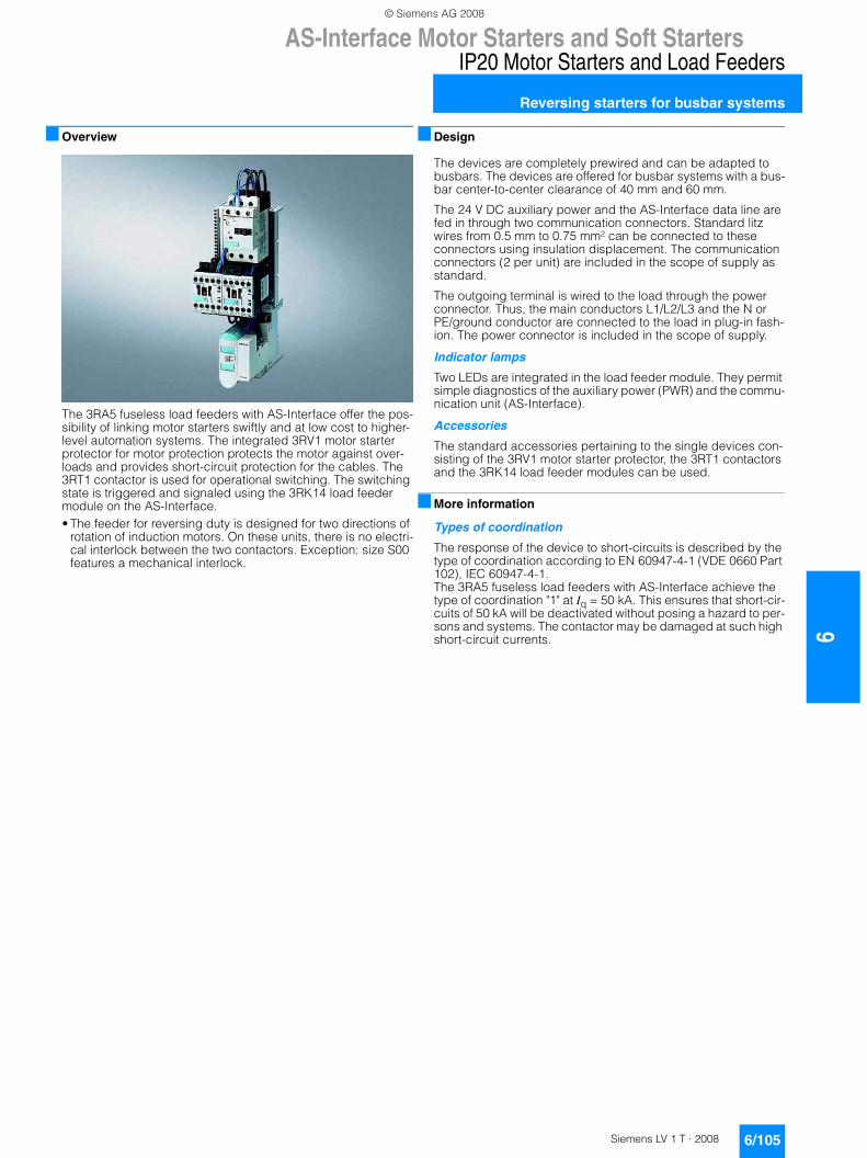
AS-Interface Motor Starters and Soft Starters
6/105Siemens LV 1 T · 2008
6
IP20 Motor Starters and Load Feeders
Reversing starters for busbar systems
■ Overview
The 3RA5 fuseless load feeders with AS-Interface offer the pos-sibility of linking motor starters swiftly and at low cost to higher-level automation systems. The integrated 3RV1 motor starter protector for motor protection protects the motor against over-loads and provides short-circuit protection for the cables. The 3RT1 contactor is used for operational switching. The switching state is triggered and signaled using the 3RK14 load feeder module on the AS-Interface.• The feeder for reversing duty is designed for two directions of
rotation of induction motors. On these units, there is no electri-cal interlock between the two contactors. Exception: size S00 features a mechanical interlock.
■ Design
The devices are completely prewired and can be adapted to busbars. The devices are offered for busbar systems with a bus-bar center-to-center clearance of 40 mm and 60 mm.
The 24 V DC auxiliary power and the AS-Interface data line are fed in through two communication connectors. Standard litz wires from 0.5 mm to 0.75 mm² can be connected to these connectors using insulation displacement. The communication connectors (2 per unit) are included in the scope of supply as standard.
The outgoing terminal is wired to the load through the power connector. Thus, the main conductors L1/L2/L3 and the N or PE/ground conductor are connected to the load in plug-in fash-ion. The power connector is included in the scope of supply.
Indicator lamps
Two LEDs are integrated in the load feeder module. They permit simple diagnostics of the auxiliary power (PWR) and the commu-nication unit (AS-Interface).
Accessories
The standard accessories pertaining to the single devices con-sisting of the 3RV1 motor starter protector, the 3RT1 contactors and the 3RK14 load feeder modules can be used.
■ More information
Types of coordination
The response of the device to short-circuits is described by the type of coordination according to EN 60947-4-1 (VDE 0660 Part 102), IEC 60947-4-1. The 3RA5 fuseless load feeders with AS-Interface achieve the type of coordination "1" at Iq = 50 kA. This ensures that short-cir-cuits of 50 kA will be deactivated without posing a hazard to per-sons and systems. The contactor may be damaged at such high short-circuit currents.
© Siemens AG 2008
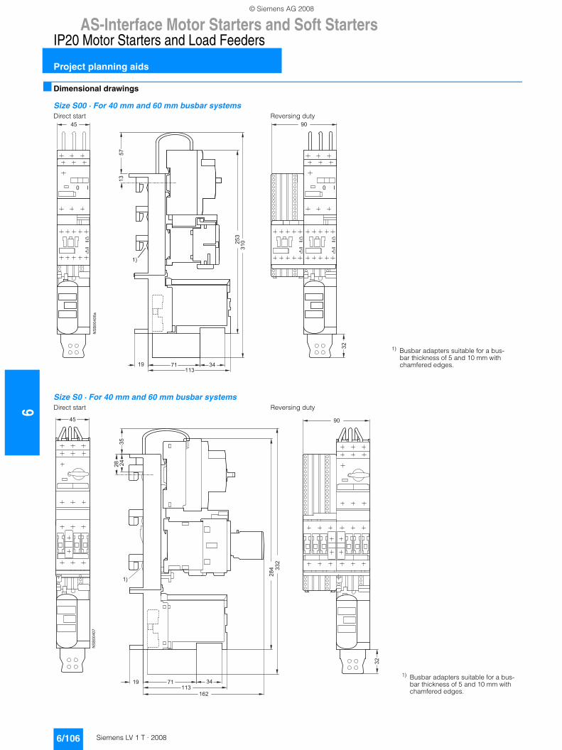
6AS-Interface Motor Starters and Soft Starters
IP20 Motor Starters and Load Feeders
Project planning aids
6/106 Siemens LV 1 T · 2008
■ Dimensional drawings
Size S00 · For 40 mm and 60 mm busbar systemsDirect start Reversing duty
Size S0 · For 40 mm and 60 mm busbar systemsDirect start Reversing duty
��
� �� �
��
��
���
��
�
��
�� �� �����
�
��
��
� ��
1) Busbar adapters suitable for a bus-bar thickness of 5 and 10 mm with chamfered edges.
1) Busbar adapters suitable for a bus-bar thickness of 5 and 10 mm with chamfered edges.
��
��
��
���
�
��
�
��
�� �� �����
��
� ��
�
��
� ��
��
© Siemens AG 2008
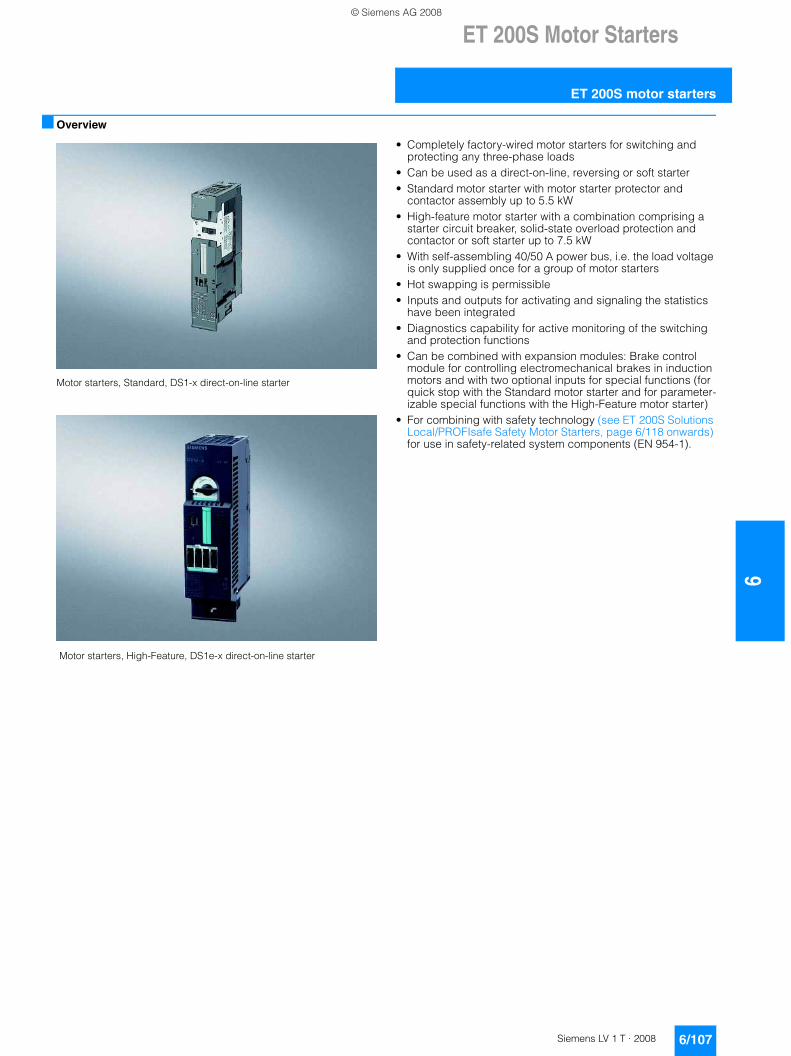
ET 200S Motor Starters
6/107Siemens LV 1 T · 2008
6
ET 200S motor starters
■ Overview
Motor starters, Standard, DS1-x direct-on-line starter
Motor starters, High-Feature, DS1e-x direct-on-line starter
• Completely factory-wired motor starters for switching and protecting any three-phase loads
• Can be used as a direct-on-line, reversing or soft starter• Standard motor starter with motor starter protector and
contactor assembly up to 5.5 kW• High-feature motor starter with a combination comprising a
starter circuit breaker, solid-state overload protection and contactor or soft starter up to 7.5 kW
• With self-assembling 40/50 A power bus, i.e. the load voltage is only supplied once for a group of motor starters
• Hot swapping is permissible• Inputs and outputs for activating and signaling the statistics
have been integrated• Diagnostics capability for active monitoring of the switching
and protection functions • Can be combined with expansion modules: Brake control
module for controlling electromechanical brakes in induction motors and with two optional inputs for special functions (for quick stop with the Standard motor starter and for parameter-izable special functions with the High-Feature motor starter)
• For combining with safety technology (see ET 200S Solutions Local/PROFIsafe Safety Motor Starters, page 6/118 onwards) for use in safety-related system components (EN 954-1).
© Siemens AG 2008
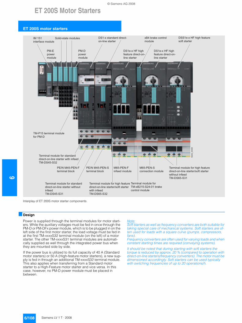
6ET 200S Motor Starters
ET 200S motor starters
6/108 Siemens LV 1 T · 2008
Interplay of ET 200S motor starter components
■ Design
Power is supplied through the terminal modules for motor start-ers. While the auxiliary voltages must be fed in once through the PM-D or PM-DFx power module, which is to be plugged in on the left side of the first motor starter, the load voltage must be fed in at the first TM-xxxxS32 terminal module (on the left) of a motor starter. The other TM-xxxxS31 terminal modules are automati-cally supplied as well through the integrated power bus when they are mounted side by side.
If the power bus is utilized to its full capacity of 40 A (Standard motor starters) or 50 A (High-feature motor starters), a new sup-ply is fed in through an additional TM-xxxxS32 terminal module. This also applies when transferring from a Standard motor starter to a High-Feature motor starter and vice versa. In this case, however, no PM-D power module must be placed in between.
Note:Soft starters as well as frequency converters are both suitable for taking special care of mechanical systems. Soft starters are of-ten used for loads with a square curve (pumps, compressors, fans). Frequency converters are often used for varying loads and when constant starting times are required (conveying systems).
It should be noted that during starting with soft starters the torque is reduced by approx. 20 % (compared to operation with direct-on-line starters/frequency converters). The motor must be dimensioned accordingly. Soft starters can be used typically with switching frequencies of up to 20 operations/h.
NS
A0_
0045
9
IM 151 interface module
PM-E power module
TM-P15 terminal module for PM-D
Solid-state modules
PM-D power module
DS1-x standard direct- on-line starter
DS1e-x HF high feature direct-on-line starter
DS1e-x HF high feature direct-on-line starter
xB4 brake control module
DSS1e-x HF high feature soft starter
Terminal module for standard direct-on-line starter with infeedTM-DS45-S32
Terminal module for high feature direct-on-line starter/soft starter with infeedTM-DS65-S32
Terminal module for high feature direct-on-line starter/soft starter without infeedTM-DS65-S31
Terminal module for standard direct-on-line starter without infeedTM-DS45-S31
Terminal module for TM-xB215-S24-01 brake control module
PE/N M45-PEN-F terminal block
PE/N M45-PEN-S terminal block
M65-PEN-F infeed module
M65-PEN-S connection module
© Siemens AG 2008
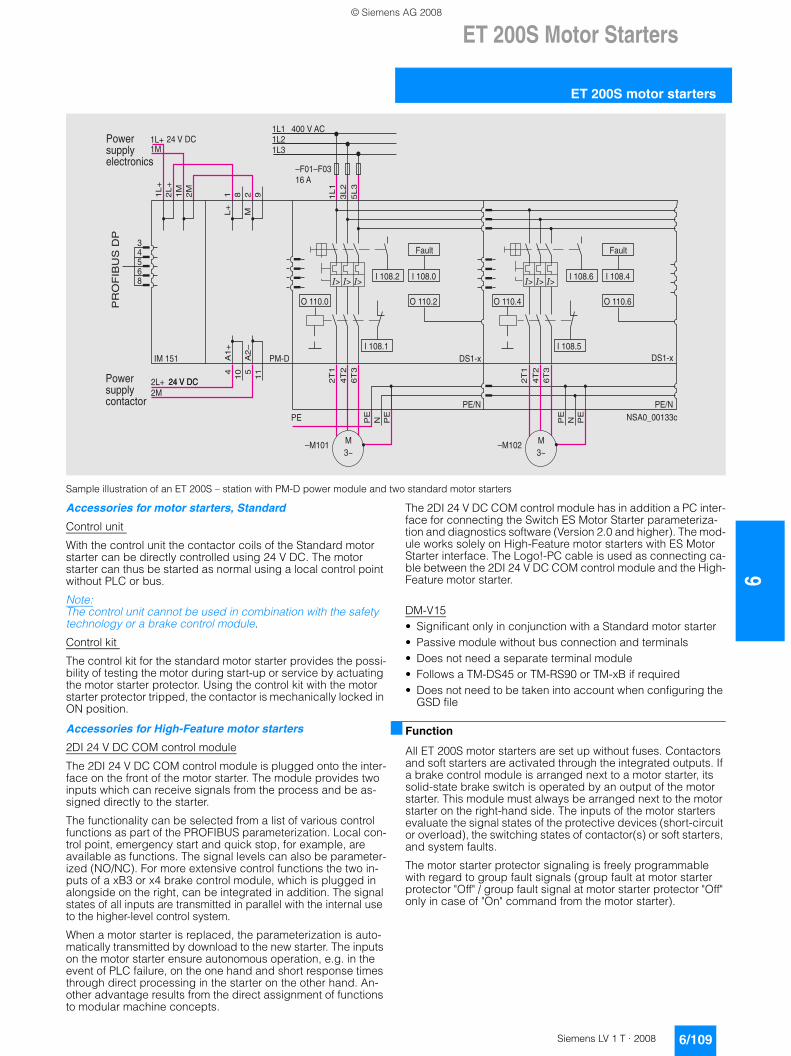
ET 200S Motor Starters
6/109Siemens LV 1 T · 2008
6
ET 200S motor starters
Sample illustration of an ET 200S – station with PM-D power module and two standard motor starters
Accessories for motor starters, Standard
Control unit
With the control unit the contactor coils of the Standard motor starter can be directly controlled using 24 V DC. The motor starter can thus be started as normal using a local control point without PLC or bus.
Note: The control unit cannot be used in combination with the safety technology or a brake control module.
Control kit
The control kit for the standard motor starter provides the possi-bility of testing the motor during start-up or service by actuating the motor starter protector. Using the control kit with the motor starter protector tripped, the contactor is mechanically locked in ON position.
Accessories for High-Feature motor starters
2DI 24 V DC COM control module
The 2DI 24 V DC COM control module is plugged onto the inter-face on the front of the motor starter. The module provides two inputs which can receive signals from the process and be as-signed directly to the starter.
The functionality can be selected from a list of various control functions as part of the PROFIBUS parameterization. Local con-trol point, emergency start and quick stop, for example, are available as functions. The signal levels can also be parameter-ized (NO/NC). For more extensive control functions the two in-puts of a xB3 or x4 brake control module, which is plugged in alongside on the right, can be integrated in addition. The signal states of all inputs are transmitted in parallel with the internal use to the higher-level control system.
When a motor starter is replaced, the parameterization is auto-matically transmitted by download to the new starter. The inputs on the motor starter ensure autonomous operation, e.g. in the event of PLC failure, on the one hand and short response times through direct processing in the starter on the other hand. An-other advantage results from the direct assignment of functions to modular machine concepts.
The 2DI 24 V DC COM control module has in addition a PC inter-face for connecting the Switch ES Motor Starter parameteriza-tion and diagnostics software (Version 2.0 and higher). The mod-ule works solely on High-Feature motor starters with ES Motor Starter interface. The Logo!-PC cable is used as connecting ca-ble between the 2DI 24 V DC COM control module and the High-Feature motor starter.
DM-V15• Significant only in conjunction with a Standard motor starter• Passive module without bus connection and terminals• Does not need a separate terminal module • Follows a TM-DS45 or TM-RS90 or TM-xB if required• Does not need to be taken into account when configuring the
GSD file
■ Function
All ET 200S motor starters are set up without fuses. Contactors and soft starters are activated through the integrated outputs. If a brake control module is arranged next to a motor starter, its solid-state brake switch is operated by an output of the motor starter. This module must always be arranged next to the motor starter on the right-hand side. The inputs of the motor starters evaluate the signal states of the protective devices (short-circuit or overload), the switching states of contactor(s) or soft starters, and system faults.
The motor starter protector signaling is freely programmable with regard to group fault signals (group fault at motor starter protector "Off" / group fault signal at motor starter protector "Off" only in case of "On" command from the motor starter).
�)��)�)�
87���
84��84�����+
% %
4�!�
87��
4�!�
)B
7
� = @�)B
)B
�77
����=
�)B�7
�)�
�)
�)�
��� ���
+�B
+8
� %
'�
�'
�'�
% � %
'�
�'
�'�
%7�* *���� *����
% C�% C�
07����
7�D
7�D
��+�������#
%/540�,��*%
)B7
%��������!��!�#�����#�
%��������!�#���#���
0���=2
0���=2�
0���=2�
5����2�
0���=2�
0���=2�
0���=2�
5����2�5����2 5����2�
����6�+&
��6�*&��6�*&
��6�*&
© Siemens AG 2008
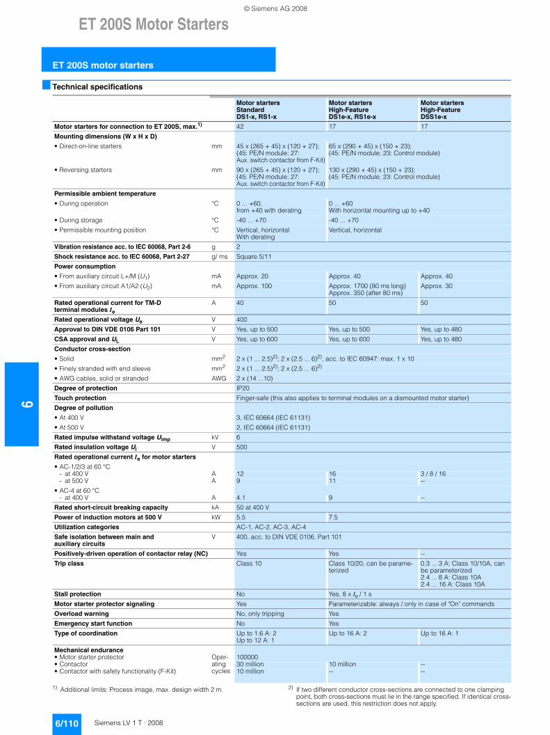
6ET 200S Motor Starters
ET 200S motor starters
6/110 Siemens LV 1 T · 2008
■ Technical specifications
1) Additional limits: Process image, max. design width 2 m. 2) If two different conductor cross-sections are connected to one clamping point, both cross-sections must lie in the range specified. If identical cross-sections are used, this restriction does not apply.
Motor startersStandardDS1-x, RS1-x
Motor startersHigh-FeatureDS1e-x, RS1e-x
Motor startersHigh-FeatureDSS1e-x
Motor starters for connection to ET 200S, max.1) 42 17 17
Mounting dimensions (W x H x D)
• Direct-on-line starters mm 45 x (265 + 45) x (120 + 27);(45: PE/N module; 27: Aux. switch contactor from F-Kit)
65 x (290 + 45) x (150 + 23);(45: PE/N module; 23: Control module)
• Reversing starters mm 90 x (265 + 45) x (120 + 27);(45: PE/N module; 27: Aux. switch contactor from F-Kit)
130 x (290 + 45) x (150 + 23);(45: PE/N module; 23: Control module)
Permissible ambient temperature
• During operation °C 0 ... +60,from +40 with derating
0 ... +60With horizontal mounting up to +40
• During storage °C -40 ... +70 -40 ... +70
• Permissible mounting position °C Vertical, horizontal With derating
Vertical, horizontal
Vibration resistance acc. to IEC 60068, Part 2-6 g 2
Shock resistance acc. to IEC 60068, Part 2-27 g/ ms Square 5/11
Power consumption
• From auxiliary circuit L+/M (U1) mA Approx. 20 Approx. 40 Approx. 40
• From auxiliary circuit A1/A2 (U2) mA Approx. 100 Approx. 1700 (80 ms long)Approx. 350 (after 80 ms)
Approx. 30
Rated operational current for TM-D terminal modules Ie
A 40 50 50
Rated operational voltage Ue V 400
Approval to DIN VDE 0106 Part 101 V Yes, up to 500 Yes, up to 500 Yes, up to 480
CSA approval and UL V Yes, up to 600 Yes, up to 600 Yes, up to 480
Conductor cross-section
• Solid mm2 2 x (1 ... 2.5)2); 2 x (2.5 ... 6)2), acc. to IEC 60947: max. 1 x 10
• Finely stranded with end sleeve mm2 2 x (1 ... 2.5)2); 2 x (2.5 ... 6)2)
• AWG cables, solid or stranded AWG 2 x (14 ...10)
Degree of protection IP20
Touch protection Finger-safe (this also applies to terminal modules on a dismounted motor starter)
Degree of pollution
• At 400 V 3, IEC 60664 (IEC 61131)
• At 500 V 2, IEC 60664 (IEC 61131)
Rated impulse withstand voltage Uimp kV 6
Rated insulation voltage Ui V 500
Rated operational current Ie for motor starters
• AC-1/2/3 at 60 °C- at 400 V A 12 16 3 / 8 / 16- at 500 V A 9 11 --
• AC-4 at 60 °C- at 400 V A 4.1 9 --
Rated short-circuit breaking capacity kA 50 at 400 V
Power of induction motors at 500 V kW 5.5 7.5
Utilization categories AC-1, AC-2, AC-3, AC-4
Safe isolation between main and auxiliary circuits
V 400, acc. to DIN VDE 0106, Part 101
Positively-driven operation of contactor relay (NC) Yes Yes --
Trip class Class 10 Class 10/20, can be parame-terized
0.3 ... 3 A: Class 10/10A, can be parameterized2.4 ... 8 A: Class 10A 2.4 ... 16 A: Class 10A
Stall protection No Yes, 8 x Ie / 1 s
Motor starter protector signaling Yes Parameterizable: always / only in case of "On" commands
Overload warning No, only tripping Yes
Emergency start function No Yes
Type of coordination Up to 1.6 A: 2Up to 12 A: 1
Up to 16 A: 2 Up to 16 A: 1
Mechanical endurance• Motor starter protector Oper-
ating cycles
100000• Contactor 30 million 10 million --• Contactor with safety functionality (F-Kit) 10 million -- --
© Siemens AG 2008
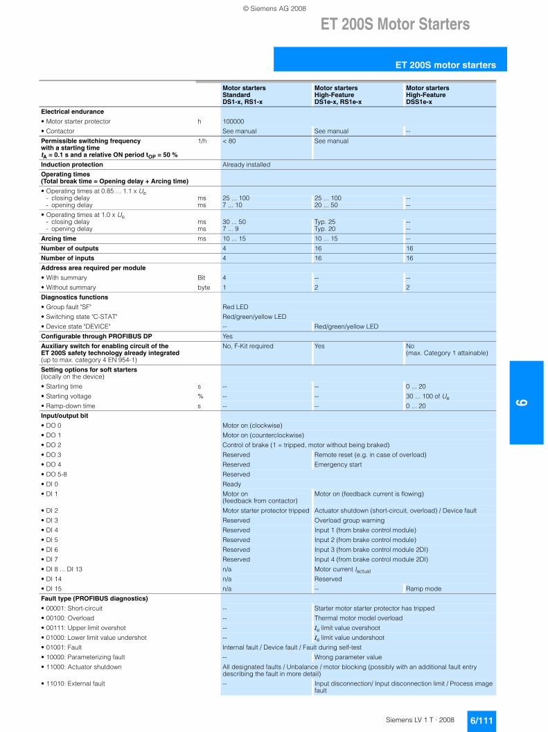
ET 200S Motor Starters
6/111Siemens LV 1 T · 2008
6
ET 200S motor starters
Motor startersStandardDS1-x, RS1-x
Motor startersHigh-FeatureDS1e-x, RS1e-x
Motor startersHigh-FeatureDSS1e-x
Electrical endurance
• Motor starter protector h 100000
• Contactor See manual See manual --
Permissible switching frequency with a starting time tA = 0.1 s and a relative ON period tOP = 50 %
1/h < 80 See manual
Induction protection Already installed
Operating times (Total break time = Opening delay + Arcing time)
• Operating times at 0.85 ... 1.1 x Ue- closing delay ms 25 ... 100 25 ... 100 --- opening delay ms 7 ... 10 20 ... 50 --
• Operating times at 1.0 x Ue- closing delay ms 30 ... 50 Typ. 25 --- opening delay ms 7 ... 9 Typ. 20 --
Arcing time ms 10 ... 15 10 ... 15 --
Number of outputs 4 16 16
Number of inputs 4 16 16
Address area required per module
• With summary Bit 4 -- --
• Without summary byte 1 2 2
Diagnostics functions
• Group fault "SF" Red LED
• Switching state "C-STAT" Red/green/yellow LED
• Device state "DEVICE" -- Red/green/yellow LED
Configurable through PROFIBUS DP Yes
Auxiliary switch for enabling circuit of the ET 200S safety technology already integrated (up to max. category 4 EN 954-1)
No, F-Kit required Yes No (max. Category 1 attainable)
Setting options for soft starters (locally on the device)
• Starting time s -- -- 0 ... 20
• Starting voltage % -- -- 30 ... 100 of Ue
• Ramp-down time s -- -- 0 ... 20
Input/output bit
• DO 0 Motor on (clockwise)
• DO 1 Motor on (counterclockwise)
• DO 2 Control of brake (1 = tripped, motor without being braked)
• DO 3 Reserved Remote reset (e.g. in case of overload)
• DO 4 Reserved Emergency start
• DO 5-8 Reserved
• DI 0 Ready
• DI 1 Motor on(feedback from contactor)
Motor on (feedback current is flowing)
• DI 2 Motor starter protector tripped Actuator shutdown (short-circuit, overload) / Device fault
• DI 3 Reserved Overload group warning
• DI 4 Reserved Input 1 (from brake control module)
• DI 5 Reserved Input 2 (from brake control module)
• DI 6 Reserved Input 3 (from brake control module 2DI)
• DI 7 Reserved Input 4 (from brake control module 2DI)
• DI 8 ... DI 13 n/a Motor current Iactual
• DI 14 n/a Reserved
• DI 15 n/a -- Ramp mode
Fault type (PROFIBUS diagnostics)
• 00001: Short-circuit -- Starter motor starter protector has tripped
• 00100: Overload -- Thermal motor model overload
• 00111: Upper limit overshot -- Ie limit value overshoot
• 01000: Lower limit value undershot -- Ie limit value undershoot
• 01001: Fault Internal fault / Device fault / Fault during self-test
• 10000: Parameterizing fault -- Wrong parameter value
• 11000: Actuator shutdown All designated faults / Unbalance / motor blocking (possibly with an additional fault entry describing the fault in more detail)
• 11010: External fault -- Input disconnection/ Input disconnection limit / Process image fault
© Siemens AG 2008
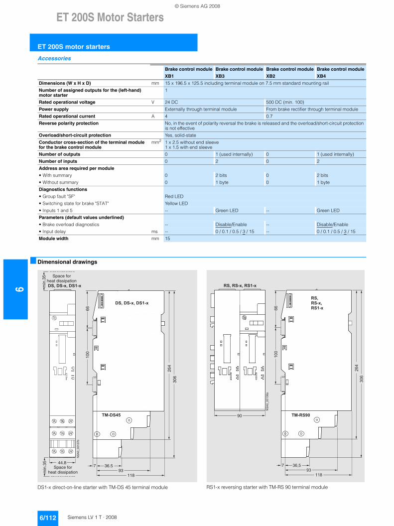
6ET 200S Motor Starters
ET 200S motor starters
6/112 Siemens LV 1 T · 2008
Accessories
■ Dimensional drawings
DS1-x direct-on-line starter with TM-DS 45 terminal module
RS1-x reversing starter with TM-RS 90 terminal module
Brake control module
XB1
Brake control module
XB3
Brake control module
XB2
Brake control module
XB4
Dimensions (W x H x D) mm 15 x 196.5 x 125.5 including terminal module on 7.5 mm standard mounting rail
Number of assigned outputs for the (left-hand) motor starter
1
Rated operational voltage V 24 DC 500 DC (min. 100)
Power supply Externally through terminal module From brake rectifier through terminal module
Rated operational current A 4 0.7
Reverse polarity protection No, in the event of polarity reversal the brake is released and the overload/short-circuit protection is not effective
Overload/short-circuit protection Yes, solid-state
Conductor cross-section of the terminal module for the brake control module
mm2 1 x 2.5 without end sleeve 1 x 1.5 with end sleeve
Number of outputs 0 1 (used internally) 0 1 (used internally)
Number of inputs 0 2 0 2
Address area required per module
• With summary 0 2 bits 0 2 bits
• Without summary 0 1 byte 0 1 byte
Diagnostics functions
• Group fault "SF" Red LED
• Switching state for brake "STAT" Yellow LED
• Inputs 1 and 5 -- Green LED -- Green LED
Parameters (default values underlined)
• Brake overload diagnostics -- Disable/Enable -- Disable/Enable
• Input delay ms -- 0 / 0.1 / 0.5 / 3 / 15 -- 0 / 0.1 / 0.5 / 3 / 15
Module width mm 15
NS
A0_
0013
7b
6610
0
7
264
306
93118
min
.35
min
.35
� � � � � � ! � � � � � !
" # � � � $ %
� � � � � � ! � � � � � !
Space forheat dissipation
Space forheat dissipation
36.544.8
���
���������
��
���
� � � �
���
� �
� �
� �
& �
& � � !
& � � � !
" # � & � ' (
& � � & � � ! � & � � � !
© Siemens AG 2008
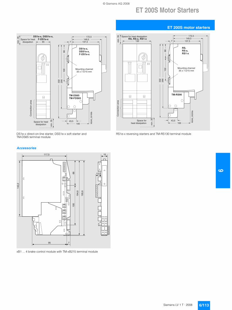
ET 200S Motor Starters
6/113Siemens LV 1 T · 2008
6
ET 200S motor starters
DS1e-x direct-on-line starter, DSS1e-x soft starter and TM-DS65 terminal module
Accessories
xB1 ... 4 brake control module with TM-xB215 terminal module
RS1e-x reversing starters and TM-RS130 terminal module
65min
. 35
min
. 35
NS
A0_
0019
9b
� � � � ! � � � � � � !
) � � � � � !
100
6629
033
2
100
7
" # � � � * %
" # � ) � � * %
� � � � !
� � � � � !
) � � � � � !
43,5
137,5149,5
172,5Space for heat
dissipation
Space for heat dissipation
Con
nect
ion
area
Mounting channel35 x 7.5/15 mm
��+�����
@�
�@�;�
��;
��
��;�
���
��
���;�
�@�;�
�
130min
. 35
min
. 35
NS
A0_
0020
0a
& � � & � � ! � & � � � !
100
6629
033
2
100
7
& �
& � � !
& � � � !
" # � & � ' (
43,5
137,5149,5
172,5Space for heat dissipation
Space for heat dissipation
Con
nect
ion
area
Mounting channel35 x 7.5/15 mm
© Siemens AG 2008
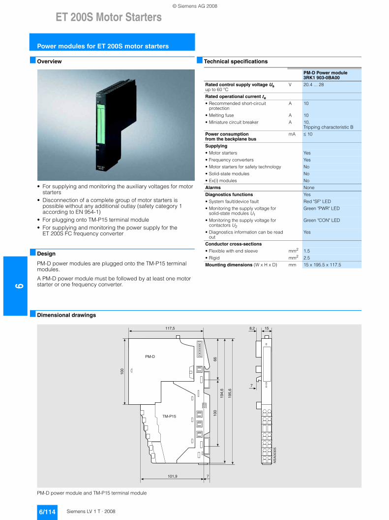
6ET 200S Motor Starters
Power modules for ET 200S motor starters
6/114 Siemens LV 1 T · 2008
■ Overview
• For supplying and monitoring the auxiliary voltages for motor starters
• Disconnection of a complete group of motor starters is possible without any additional outlay (safety category 1 according to EN 954-1)
• For plugging onto TM-P15 terminal module• For supplying and monitoring the power supply for the
ET 200S FC frequency converter
■ Design
PM-D power modules are plugged onto the TM-P15 terminal modules.
A PM-D power module must be followed by at least one motor starter or one frequency converter.
■ Technical specifications
■ Dimensional drawings
PM-D power module and TM-P15 terminal module
PM-D Power module3RK1 903-0BA00
Rated control supply voltage Us up to 60 °C
V 20.4 ... 28
Rated operational current Ie
• Recommended short-circuit protection
A 10
• Melting fuse A 10
• Miniature circuit breaker A 10, Tripping characteristic B
Power consumption from the backplane bus
mA ≤ 10
Supplying
• Motor starters Yes
• Frequency converters Yes
• Motor starters for safety technology No
• Solid-state modules No
• Ex(i) modules No
Alarms None
Diagnostics functions Yes
• System fault/device fault Red "SF" LED
• Monitoring the supply voltage for solid-state modules U1
Green "PWR" LED
• Monitoring the supply voltage for contactors U2
Green "CON" LED
• Diagnostics information can be read out
Yes
Conductor cross-sections
• Flexible with end sleeve mm2 1.5
• Rigid mm2 2.5
Mounting dimensions (W x H x D) mm 15 x 195.5 x 117.5
��+�����
���;@
�@�;�
���
��=;
�
���
��
���;�
%7�*
'7�%��
�@�;�
�
© Siemens AG 2008
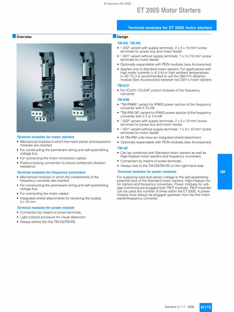
ET 200S Motor Starters
6/115Siemens LV 1 T · 2008
6
Terminal modules for ET 200S motor starters
■ Overview
Terminal modules for motor starters• Mechanical modules in which the motor starter and expansion
modules are inserted• For constructing the permanent wiring and self-assembling
voltage bus• For connecting the motor connection cables• Positive-locking connection to ensure enhanced vibration
resistance
Terminal modules for frequency converters• Mechanical modules in which the components of the
frequency converter are inserted• For constructing the permanent wiring and self-assembling
voltage bus• For connecting the motor cables• Integrated shield attachments for receiving the busbar
3 x 10 mm
Terminal modules for power module• Connection by means of screw terminals• Light colored enclosure for visual distinction• Always before the first TM-DS/TM-RS
■ Design
TM-DS, TM-RS • "–S32" variant with supply terminals: 2 x 3 x 10 mm² screw
terminals for power bus and motor feeder• "–S31" variant without supply terminals: 1 x 3 x 10 mm² screw
terminals for motor feeder• Optionally expandable with PE/N modules (see Accessories)• Applies only to Standard motor starters: For applications with
high motor currents (> 6.3 A) or high ambient temperatures (> 40 °C) it is recommended to use the DM-V15 distance module (See Accessories) between two DS1-x motor starters
TM-ICU• For ICU24 / ICU24F control modules of the frequency
converter
TM-IPM• "TM-IPM65" variant for IPM25 power section of the frequency
converter with 0.75 kW• "TM-IPM130" variant for IPM25 power section of the frequency
converter with 2.2 or 4.0 kW• "–S32" variant with supply terminals: 2 x 3 x 10 mm² screw
terminals for power bus and motor feeder• "–S31" variant without supply terminals: 1 x 3 x 10 mm² screw
terminals for motor feeder• All TM-IPM units have an integrated shield attachment• Optionally expandable with PE/N modules (see Accessories)
TM-xB • Can be combined with Standard motor starters as well as
High-Feature motor starters and frequency converters• Connection by means of screw terminals• Always next to the TM-DS/TM-RS on the right-hand side
Terminal modules for power modules
For supplying load and sensor voltage to the self-assembling potential bars of the Standard motor starters, High-Feature mo-tor starters and frequency converters. Power modules for volt-age monitoring are plugged onto TM-P modules. TM-P modules can be used any number of times within the ET 200S. A power module must always be plugged upstream from the first motor starter/frequency converter.
© Siemens AG 2008
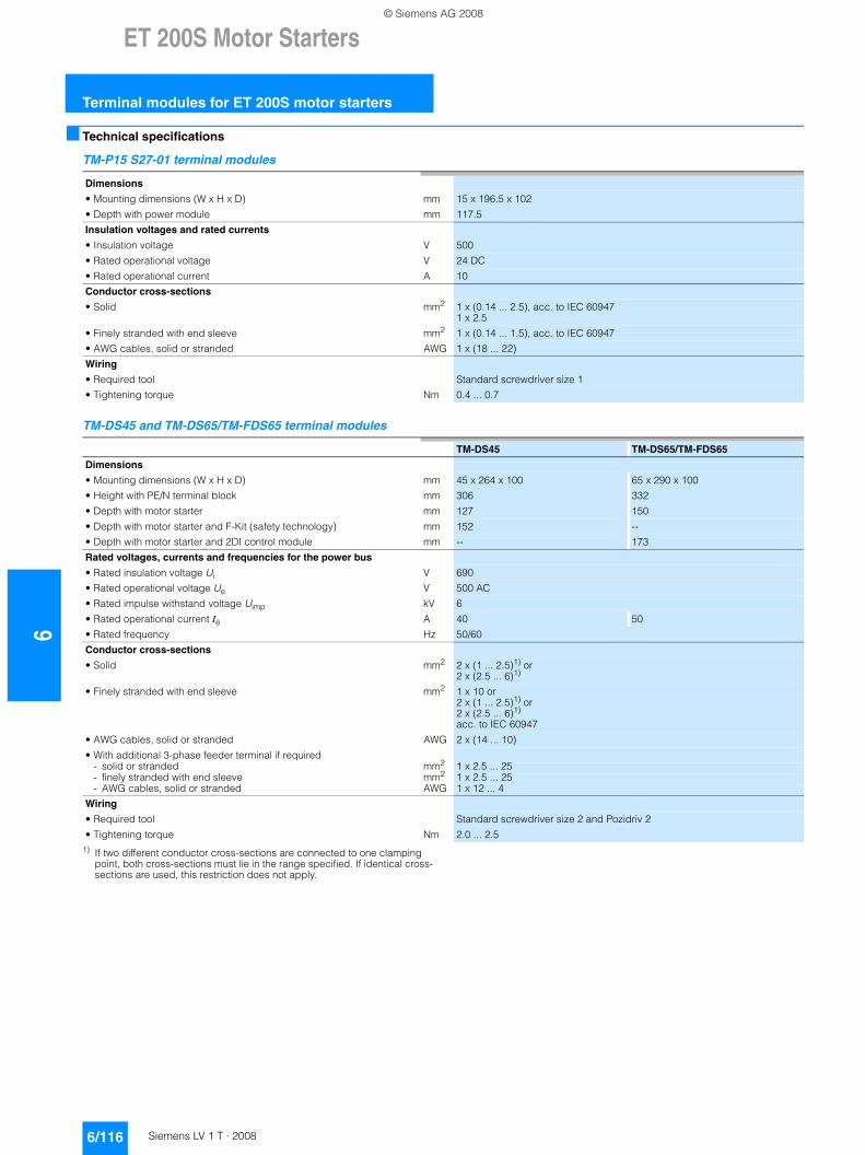
6ET 200S Motor Starters
Terminal modules for ET 200S motor starters
6/116 Siemens LV 1 T · 2008
■ Technical specifications
TM-P15 S27-01 terminal modules
TM-DS45 and TM-DS65/TM-FDS65 terminal modules
1) If two different conductor cross-sections are connected to one clamping point, both cross-sections must lie in the range specified. If identical cross-sections are used, this restriction does not apply.
Dimensions
• Mounting dimensions (W x H x D) mm 15 x 196.5 x 102
• Depth with power module mm 117.5
Insulation voltages and rated currents
• Insulation voltage V 500
• Rated operational voltage V 24 DC
• Rated operational current A 10
Conductor cross-sections
• Solid mm2 1 x (0.14 ... 2.5), acc. to IEC 60947 1 x 2.5
• Finely stranded with end sleeve mm2 1 x (0.14 ... 1.5), acc. to IEC 60947
• AWG cables, solid or stranded AWG 1 x (18 ... 22)
Wiring
• Required tool Standard screwdriver size 1
• Tightening torque Nm 0.4 ... 0.7
TM-DS45 TM-DS65/TM-FDS65
Dimensions
• Mounting dimensions (W x H x D) mm 45 x 264 x 100 65 x 290 x 100
• Height with PE/N terminal block mm 306 332
• Depth with motor starter mm 127 150
• Depth with motor starter and F-Kit (safety technology) mm 152 --
• Depth with motor starter and 2DI control module mm -- 173
Rated voltages, currents and frequencies for the power bus
• Rated insulation voltage Ui V 690
• Rated operational voltage Ue V 500 AC
• Rated impulse withstand voltage Uimp kV 6
• Rated operational current Ie A 40 50
• Rated frequency Hz 50/60
Conductor cross-sections
• Solid mm2 2 x (1 ... 2.5)1) or 2 x (2.5 ... 6)1)
• Finely stranded with end sleeve mm2 1 x 10 or2 x (1 ... 2.5)1) or2 x (2.5 ... 6)1) acc. to IEC 60947
• AWG cables, solid or stranded AWG 2 x (14 ... 10)
• With additional 3-phase feeder terminal if required- solid or stranded mm2 1 x 2.5 ... 25- finely stranded with end sleeve mm2 1 x 2.5 ... 25- AWG cables, solid or stranded AWG 1 x 12 ... 4
Wiring
• Required tool Standard screwdriver size 2 and Pozidriv 2
• Tightening torque Nm 2.0 ... 2.5
© Siemens AG 2008
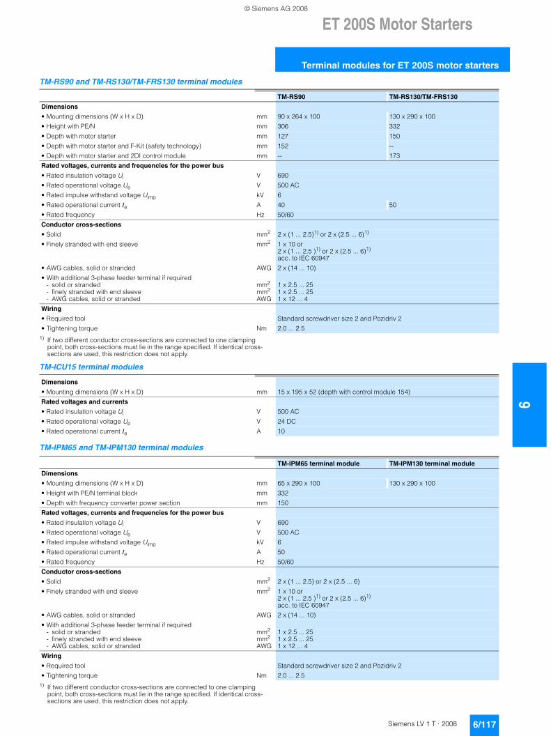
ET 200S Motor Starters
6/117Siemens LV 1 T · 2008
6
Terminal modules for ET 200S motor starters
TM-RS90 and TM-RS130/TM-FRS130 terminal modules
1) If two different conductor cross-sections are connected to one clamping point, both cross-sections must lie in the range specified. If identical cross-sections are used, this restriction does not apply.
TM-ICU15 terminal modules
TM-IPM65 and TM-IPM130 terminal modules
1) If two different conductor cross-sections are connected to one clamping point, both cross-sections must lie in the range specified. If identical cross-sections are used, this restriction does not apply.
TM-RS90 TM-RS130/TM-FRS130
Dimensions
• Mounting dimensions (W x H x D) mm 90 x 264 x 100 130 x 290 x 100
• Height with PE/N mm 306 332
• Depth with motor starter mm 127 150
• Depth with motor starter and F-Kit (safety technology) mm 152 --
• Depth with motor starter and 2DI control module mm -- 173
Rated voltages, currents and frequencies for the power bus
• Rated insulation voltage Ui V 690
• Rated operational voltage Ue V 500 AC
• Rated impulse withstand voltage Uimp kV 6
• Rated operational current Ie A 40 50
• Rated frequency Hz 50/60
Conductor cross-sections
• Solid mm2 2 x (1 ... 2.5)1) or 2 x (2.5 ... 6)1)
• Finely stranded with end sleeve mm2 1 x 10 or2 x (1 ... 2.5 )1) or 2 x (2.5 ... 6)1) acc. to IEC 60947
• AWG cables, solid or stranded AWG 2 x (14 ... 10)
• With additional 3-phase feeder terminal if required- solid or stranded mm2 1 x 2.5 ... 25- finely stranded with end sleeve mm2 1 x 2.5 ... 25- AWG cables, solid or stranded AWG 1 x 12 ... 4
Wiring
• Required tool Standard screwdriver size 2 and Pozidriv 2
• Tightening torque Nm 2.0 ... 2.5
Dimensions
• Mounting dimensions (W x H x D) mm 15 x 195 x 52 (depth with control module 154)
Rated voltages and currents
• Rated insulation voltage Ui V 500 AC
• Rated operational voltage Ue V 24 DC
• Rated operational current Ie A 10
TM-IPM65 terminal module TM-IPM130 terminal module
Dimensions
• Mounting dimensions (W x H x D) mm 65 x 290 x 100 130 x 290 x 100
• Height with PE/N terminal block mm 332
• Depth with frequency converter power section mm 150
Rated voltages, currents and frequencies for the power bus
• Rated insulation voltage Ui V 690
• Rated operational voltage Ue V 500 AC
• Rated impulse withstand voltage Uimp kV 6
• Rated operational current Ie A 50
• Rated frequency Hz 50/60
Conductor cross-sections
• Solid mm2 2 x (1 ... 2.5) or 2 x (2.5 ... 6)
• Finely stranded with end sleeve mm2 1 x 10 or2 x (1 ... 2.5 )1) or 2 x (2.5 ... 6)1) acc. to IEC 60947
• AWG cables, solid or stranded AWG 2 x (14 ... 10)
• With additional 3-phase feeder terminal if required- solid or stranded mm2 1 x 2.5 ... 25- finely stranded with end sleeve mm2 1 x 2.5 ... 25- AWG cables, solid or stranded AWG 1 x 12 ... 4
Wiring
• Required tool Standard screwdriver size 2 and Pozidriv 2
• Tightening torque Nm 2.0 ... 2.5
© Siemens AG 2008
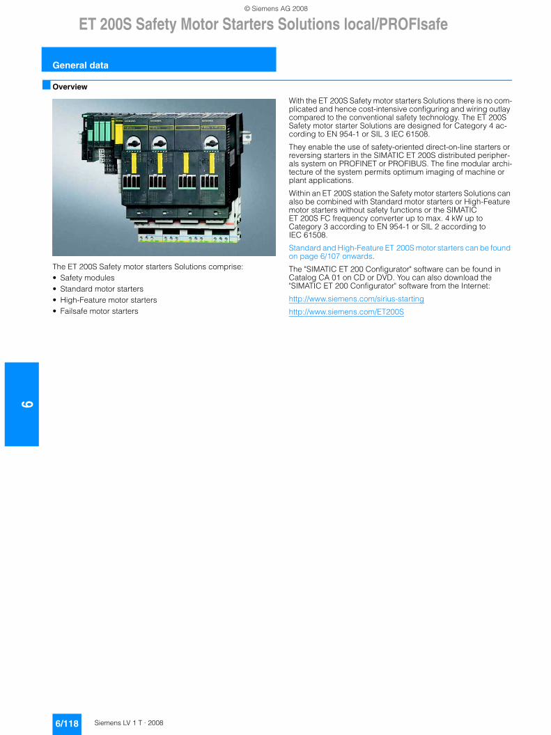
6ET 200S Safety Motor Starters Solutions local/PROFIsafe
General data
6/118 Siemens LV 1 T · 2008
■ Overview
The ET 200S Safety motor starters Solutions comprise:• Safety modules• Standard motor starters• High-Feature motor starters • Failsafe motor starters
With the ET 200S Safety motor starters Solutions there is no com-plicated and hence cost-intensive configuring and wiring outlay compared to the conventional safety technology. The ET 200S Safety motor starter Solutions are designed for Category 4 ac-cording to EN 954-1 or SIL 3 IEC 61508.
They enable the use of safety-oriented direct-on-line starters or reversing starters in the SIMATIC ET 200S distributed peripher-als system on PROFINET or PROFIBUS. The fine modular archi-tecture of the system permits optimum imaging of machine or plant applications.
Within an ET 200S station the Safety motor starters Solutions can also be combined with Standard motor starters or High-Feature motor starters without safety functions or the SIMATIC ET 200S FC frequency converter up to max. 4 kW up to Category 3 according to EN 954-1 or SIL 2 according to IEC 61508.
Standard and High-Feature ET 200S motor starters can be found on page 6/107 onwards.
The "SIMATIC ET 200 Configurator" software can be found in Catalog CA 01 on CD or DVD. You can also download the "SIMATIC ET 200 Configurator" software from the Internet:
http://www.siemens.com/sirius-starting
http://www.siemens.com/ET200S
© Siemens AG 2008
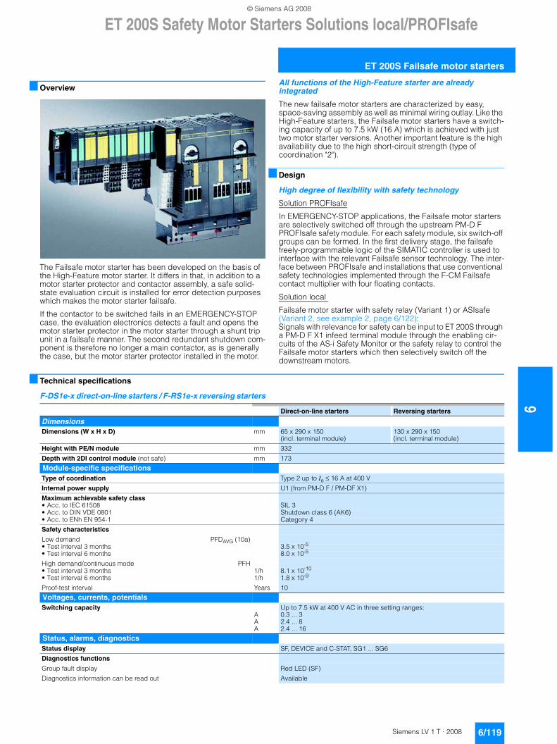
ET 200S Safety Motor Starters Solutions local/PROFIsafe
6/119Siemens LV 1 T · 2008
6
ET 200S Failsafe motor starters
■ Overview
The Failsafe motor starter has been developed on the basis of the High-Feature motor starter. It differs in that, in addition to a motor starter protector and contactor assembly, a safe solid-state evaluation circuit is installed for error detection purposes which makes the motor starter failsafe.
If the contactor to be switched fails in an EMERGENCY-STOP case, the evaluation electronics detects a fault and opens the motor starter protector in the motor starter through a shunt trip unit in a failsafe manner. The second redundant shutdown com-ponent is therefore no longer a main contactor, as is generally the case, but the motor starter protector installed in the motor.
All functions of the High-Feature starter are already integrated
The new failsafe motor starters are characterized by easy, space-saving assembly as well as minimal wiring outlay. Like the High-Feature starters, the Failsafe motor starters have a switch-ing capacity of up to 7.5 kW (16 A) which is achieved with just two motor starter versions. Another important feature is the high availability due to the high short-circuit strength (type of coordination "2").
■ Design
High degree of flexibility with safety technology
Solution PROFIsafe
In EMERGENCY-STOP applications, the Failsafe motor starters are selectively switched off through the upstream PM-D F PROFIsafe safety module. For each safety module, six switch-off groups can be formed. In the first delivery stage, the failsafe freely-programmable logic of the SIMATIC controller is used to interface with the relevant Failsafe sensor technology. The inter-face between PROFIsafe and installations that use conventional safety technologies implemented through the F-CM Failsafe contact multiplier with four floating contacts.
Solution local
Failsafe motor starter with safety relay (Variant 1) or ASIsafe (Variant 2, see example 2, page 6/122): Signals with relevance for safety can be input to ET 200S through a PM-D F X1 infeed terminal module through the enabling cir-cuits of the AS-i Safety Monitor or the safety relay to control the Failsafe motor starters which then selectively switch off the downstream motors.
■ Technical specifications
F-DS1e-x direct-on-line starters / F-RS1e-x reversing starters
Direct-on-line starters Reversing starters
Dimensions Dimensions (W x H x D) mm 65 x 290 x 150
(incl. terminal module)130 x 290 x 150 (incl. terminal module)
Height with PE/N module mm 332
Depth with 2DI control module (not safe) mm 173
Module-specific specificationsType of coordination Type 2 up to Ie ≤ 16 A at 400 V
Internal power supply U1 (from PM-D F / PM-DF X1)
Maximum achievable safety class• Acc. to IEC 61508 SIL 3• Acc. to DIN VDE 0801 Shutdown class 6 (AK6)• Acc. to ENh EN 954-1 Category 4
Safety characteristics
Low demand PFDAVG (10a)• Test interval 3 months 3.5 x 10⁻⁵
• Test interval 6 months 8.0 x 10⁻⁵
High demand/continuous mode PFH• Test interval 3 months 1/h 8.1 x 10⁻¹⁰
• Test interval 6 months 1/h 1.8 x 10⁻⁹
Proof-test interval Years 10
Voltages, currents, potentialsSwitching capacity
AAA
Up to 7.5 kW at 400 V AC in three setting ranges:0.3 ... 32.4 ... 82.4 ... 16
Status, alarms, diagnosticsStatus display SF, DEVICE and C-STAT, SG1 ... SG6
Diagnostics functions
Group fault display Red LED (SF)
Diagnostics information can be read out Available
© Siemens AG 2008
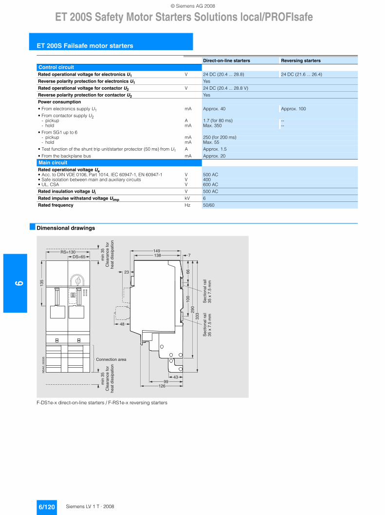
6ET 200S Safety Motor Starters Solutions local/PROFIsafe
ET 200S Failsafe motor starters
6/120 Siemens LV 1 T · 2008
■ Dimensional drawings
F-DS1e-x direct-on-line starters / F-RS1e-x reversing starters
Control circuit Rated operational voltage for electronics U1 V 24 DC (20.4 ... 28.8) 24 DC (21.6 ... 26.4)
Reverse polarity protection for electronics U1 Yes
Rated operational voltage for contactor U2 V 24 DC (20.4 ... 28.8 V)
Reverse polarity protection for contactor U2 Yes
Power consumption
• From electronics supply U1 mA Approx. 40 Approx. 100
• From contactor supply U2- pickup A 1.7 (for 80 ms) --- hold mA Max. 350 --
• From SG1 up to 6- pickup mA 250 (for 200 ms)- hold mA Max. 55
• Test function of the shunt trip unit/starter protector (50 ms) from U1 A Approx. 1.5
• From the backplane bus mA Approx. 20
Main circuit Rated operational voltage Ue• Acc. to DIN VDE 0106, Part 1014, IEC 60947-1, EN 60947-1 V 500 AC• Safe isolation between main and auxiliary circuits V 400• UL, CSA V 600 AC
Rated insulation voltage Ui V 500 AC
Rated impulse withstand voltage Uimp kV 6
Rated frequency Hz 50/60
Direct-on-line starters Reversing starters
66
7138149
48
NS
A0_
0033
5
4399
126
100
290
333
23
DS=65RS=130
135
Sec
tiona
l rai
l35
x 7
.5 m
m
Connection area
min
35
Cle
aran
ce fo
rhe
at d
issi
patio
n
min
35
Cle
aran
ce fo
rhe
at d
issi
patio
n
Sec
tiona
l rai
l35
x 7
.5 m
m
© Siemens AG 2008
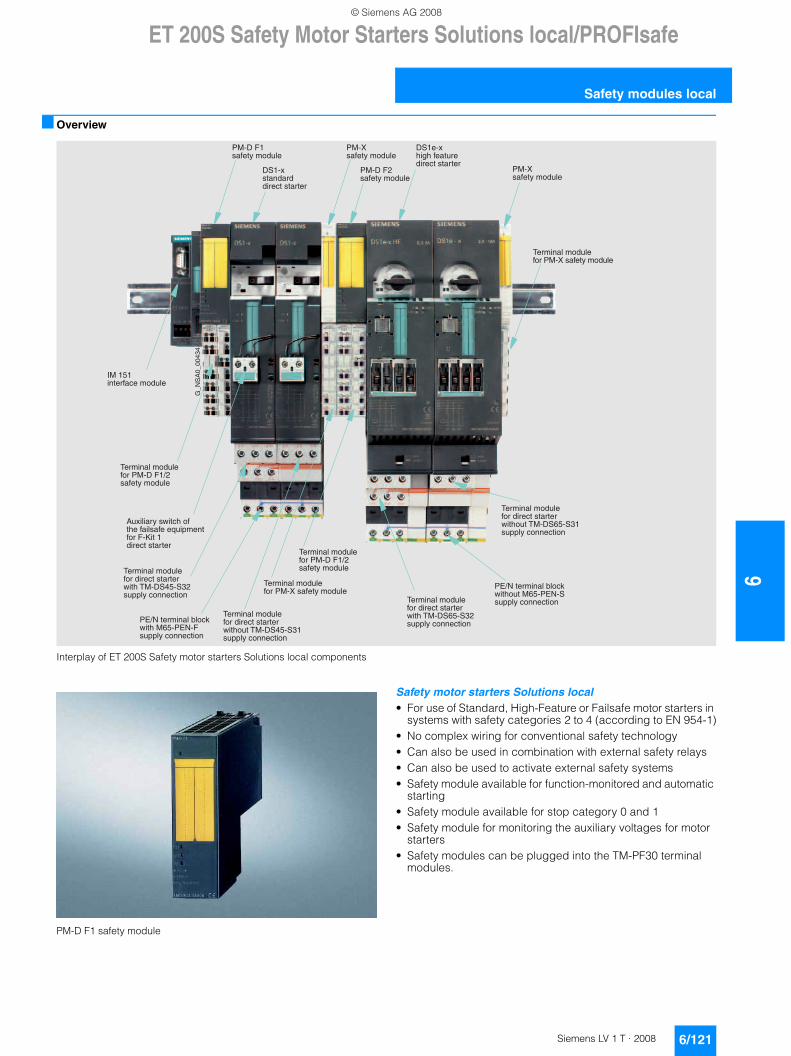
ET 200S Safety Motor Starters Solutions local/PROFIsafe
6/121Siemens LV 1 T · 2008
6
Safety modules local
■ Overview
Interplay of ET 200S Safety motor starters Solutions local components
PM-D F1 safety module
Safety motor starters Solutions local• For use of Standard, High-Feature or Failsafe motor starters in
systems with safety categories 2 to 4 (according to EN 954-1)• No complex wiring for conventional safety technology• Can also be used in combination with external safety relays• Can also be used to activate external safety systems• Safety module available for function-monitored and automatic
starting• Safety module available for stop category 0 and 1• Safety module for monitoring the auxiliary voltages for motor
starters• Safety modules can be plugged into the TM-PF30 terminal
modules.
'�����!�����!�����%7�-�����������!�
'�����!�����!���������#�������������'7�*����������!��#����#����
'�����!�����!�����%7�*�4�C����������!�
'�����!�����!�����%7�-�����������!�
'�����!�����!���������#����������������'7�*�����������!��#����#����
'�����!�����!���������#�������������'7�*����������!��#����#����
+���!��������#����������!�����E�����������4�A��������#��������
'�����!�����!�����%7�*�4�C����������!�
%7�*�4�����������!�
*��������������#��������
%7�-����������!�
%7�*�4����������!�
*�������"������������#��������
%7�-����������!�
'�����!�����!���������#����������������'7�*�����������!��#����#����
F���+�������
07����������#������!�
% C��������!� !�#(��������7���% �������!��#����#����
% C��������!� !�#(�����7���% ��4����!��#����#����
© Siemens AG 2008
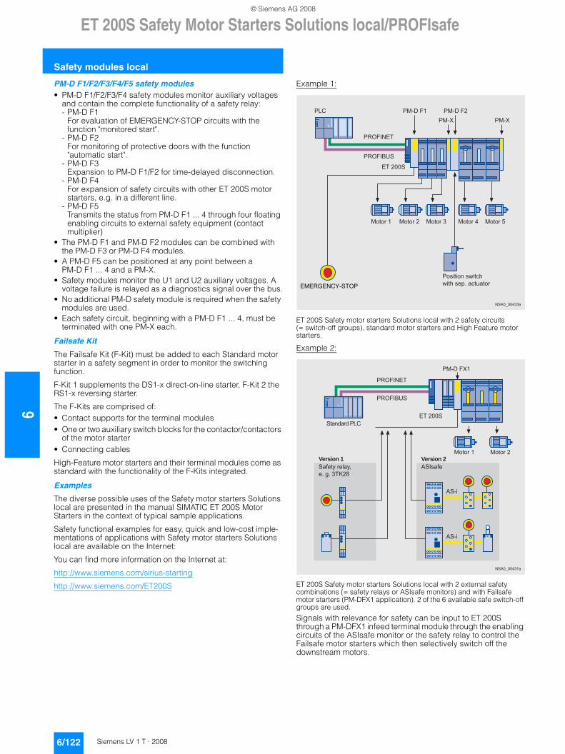
6ET 200S Safety Motor Starters Solutions local/PROFIsafe
Safety modules local
6/122 Siemens LV 1 T · 2008
PM-D F1/F2/F3/F4/F5 safety modules• PM-D F1/F2/F3/F4 safety modules monitor auxiliary voltages
and contain the complete functionality of a safety relay:- PM-D F1
For evaluation of EMERGENCY-STOP circuits with the function "monitored start".
- PM-D F2 For monitoring of protective doors with the function "automatic start".
- PM-D F3 Expansion to PM-D F1/F2 for time-delayed disconnection.
- PM-D F4 For expansion of safety circuits with other ET 200S motor starters, e.g. in a different line.
- PM-D F5 Transmits the status from PM-D F1 ... 4 through four floating enabling circuits to external safety equipment (contact multiplier)
• The PM-D F1 and PM-D F2 modules can be combined with the PM-D F3 or PM-D F4 modules.
• A PM-D F5 can be positioned at any point between a PM-D F1 ... 4 and a PM-X.
• Safety modules monitor the U1 and U2 auxiliary voltages. A voltage failure is relayed as a diagnostics signal over the bus.
• No additional PM-D safety module is required when the safety modules are used.
• Each safety circuit, beginning with a PM-D F1 ... 4, must be terminated with one PM-X each.
Failsafe Kit
The Failsafe Kit (F-Kit) must be added to each Standard motor starter in a safety segment in order to monitor the switching function.
F-Kit 1 supplements the DS1-x direct-on-line starter, F-Kit 2 the RS1-x reversing starter.
The F-Kits are comprised of: • Contact supports for the terminal modules • One or two auxiliary switch blocks for the contactor/contactors
of the motor starter• Connecting cables
High-Feature motor starters and their terminal modules come as standard with the functionality of the F-Kits integrated.
Examples
The diverse possible uses of the Safety motor starters Solutions local are presented in the manual SIMATIC ET 200S Motor Starters in the context of typical sample applications.
Safety functional examples for easy, quick and low-cost imple-mentations of applications with Safety motor starters Solutions local are available on the Internet:
You can find more information on the Internet at:
http://www.siemens.com/sirius-starting
http://www.siemens.com/ET200S
Example 1:
ET 200S Safety motor starters Solutions local with 2 safety circuits (= switch-off groups), standard motor starters and High Feature motor starters.
Example 2:
ET 200S Safety motor starters Solutions local with 2 external safety combinations (= safety relays or ASIsafe monitors) and with Failsafe motor starters (PM-DFX1 application). 2 of the 6 available safe switch-off groups are used.
Signals with relevance for safety can be input to ET 200S through a PM-DFX1 infeed terminal module through the enabling circuits of the ASIsafe monitor or the safety relay to control the Failsafe motor starters which then selectively switch off the downstream motors.
NSA0_00433a
ET 200S
PM-D F1 PM-D F2 PM-X PM-X
PROFIBUS
PROFINET
PLC
EMERGENCY-STOPPosition switchwith sep. actuator
Motor 4 Motor 5Motor 1 Motor 2 Motor 3
ET 200S
PROFIBUS
PROFINET
PM-D FX1
ASIsafe
AS-i
AS-i
NSA0_00431a
Safety relay, e. g. 3TK28
Version 2 Version 1
Standard PLC
Motor 1 Motor 2
© Siemens AG 2008
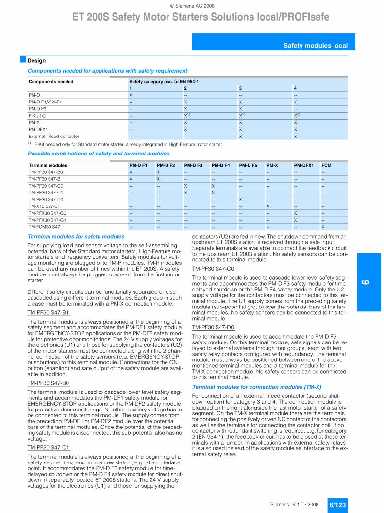
ET 200S Safety Motor Starters Solutions local/PROFIsafe
6/123Siemens LV 1 T · 2008
6
Safety modules local
■ Design
Components needed for applications with safety requirement
1) F-Kit needed only for Standard motor starter; already integrated in High-Feature motor starter.
Possible combinations of safety and terminal modules
Terminal modules for safety modules
For supplying load and sensor voltage to the self-assembling potential bars of the Standard motor starters, High-Feature mo-tor starters and frequency converters. Safety modules for volt-age monitoring are plugged onto TM-P modules. TM-P modules can be used any number of times within the ET 200S. A safety module must always be plugged upstream from the first motor starter.
Different safety circuits can be functionally separated or else cascaded using different terminal modules. Each group in such a case must be terminated with a PM-X connection module.
TM-PF30 S47-B1
The terminal module is always positioned at the beginning of a safety segment and accommodates the PM-DF1 safety module for EMERGENCY-STOP applications or the PM-DF2 safety mod-ule for protective door monitorings. The 24 V supply voltages for the electronics (U1) and those for supplying the contactors (U2) of the motor starters must be connected along with the 2-chan-nel connection of the safety sensors (e.g. EMERGENCY-STOP pushbuttons) to this terminal module. Connections for the ON button (enabling) and safe output of the safety module are avail-able in addition.
TM-PF30 S47-B0
The terminal module is used to cascade lower level safety seg-ments and accommodates the PM-DF1 safety module for EMERGENCY-STOP applications or the PM-DF2 safety module for protective door monitorings. No other auxiliary voltage has to be connected to this terminal module. The supply comes from the preceding PM-DF1 or PM-DF2 module over the potential bars of the terminal modules. Once the potential of the preced-ing safety module is disconnected, this sub-potential also has no voltage.
TM-PF30 S47-C1
The terminal module is always positioned at the beginning of a safety segment expansion in a new station, e.g. at an interlace point. It accommodates the PM-D F3 safety module for time-delayed shutdown or the PM-D F4 safety module for direct shut-down in separately located ET 200S stations. The 24 V supply voltages for the electronics (U1) and those for supplying the
contactors (U2) are fed in new. The shutdown command from an upstream ET 200S station is received through a safe input. Separate terminals are available to connect the feedback circuit to the upstream ET 200S station. No safety sensors can be con-nected to this terminal module.
TM-PF30 S47-C0
The terminal module is used to cascade lower level safety seg-ments and accommodates the PM-D F3 safety module for time-delayed shutdown or the PM-D F4 safety module. Only the U2 supply voltage for the contactors must be connected to this ter-minal module. The U1 supply comes from the preceding safety module (sub-potential group) over the potential bars of the ter-minal modules. No safety sensors can be connected to this ter-minal module.
TM-PF30 S47-D0
The terminal module is used to accommodate the PM-D F5 safety module. On this terminal module, safe signals can be re-layed to external systems through four groups, each with two safety relay contacts configured with redundancy. The terminal module must always be positioned between one of the above mentioned terminal modules and a terminal module for the TM-X connection module. No safety sensors can be connected to this terminal module.
Terminal modules for connection modules (TM-X)
For connection of an external infeed contactor (second shut-down option) for category 3 and 4. The connection module is plugged on the right alongside the last motor starter of a safety segment. On the TM-X terminal module there are the terminals for connecting the positively driven NC contact of the contactors as well as the terminals for connecting the contactor coil. If no contactor with redundant switching is required, e.g. for category 2 (EN 954-1), the feedback circuit has to be closed at these ter-minals with a jumper. In applications with external safety relays it is also used instead of the safety module as interface to the ex-ternal safety relay.
Components needed Safety category acc. to EN 954-1
1 2 3 4
PM-D X -- -- --
PM-D F1/-F2/-F4 -- X X X
PM-D F3 -- X X --
F-Kit 1/2 -- X1) X1) X1)
PM-X -- X X X
PM-DFX1 -- X X X
External infeed contactor -- -- X X
Terminal modules PM-D F1 PM-D F2 PM-D F3 PM-D F4 PM-D F5 PM-X PM-DFX1 FCM
TM-PF30 S47-B0 X X -- -- -- -- -- --
TM-PF30 S47-B1 X X -- -- -- -- -- --
TM-PF30 S47-C0 -- -- X X -- -- -- --
TM-PF30 S47-C1 -- -- X X -- -- -- --
TM-PF30 S47-D0 -- -- -- -- X -- -- --
TM-X15 S27-01 -- -- -- -- -- X -- --
TM-PFX30 S47-G0 -- -- -- -- -- -- X --
TM-PFX30 S47-G1 -- -- -- -- -- -- X --
TM-FCM30 S47 -- -- -- -- -- -- -- X
© Siemens AG 2008
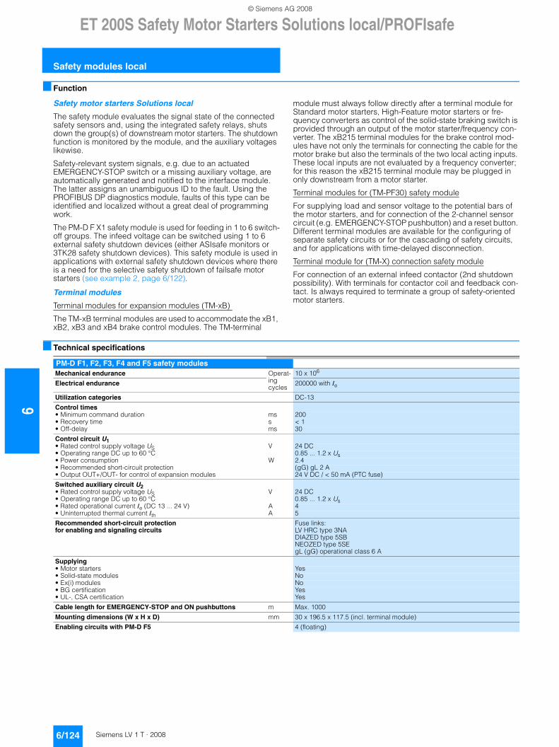
6ET 200S Safety Motor Starters Solutions local/PROFIsafe
Safety modules local
6/124 Siemens LV 1 T · 2008
■ Function
Safety motor starters Solutions local
The safety module evaluates the signal state of the connected safety sensors and, using the integrated safety relays, shuts down the group(s) of downstream motor starters. The shutdown function is monitored by the module, and the auxiliary voltages likewise.
Safety-relevant system signals, e.g. due to an actuated EMERGENCY-STOP switch or a missing auxiliary voltage, are automatically generated and notified to the interface module. The latter assigns an unambiguous ID to the fault. Using the PROFIBUS DP diagnostics module, faults of this type can be identified and localized without a great deal of programming work.
The PM-D F X1 safety module is used for feeding in 1 to 6 switch-off groups. The infeed voltage can be switched using 1 to 6 external safety shutdown devices (either ASIsafe monitors or 3TK28 safety shutdown devices). This safety module is used in applications with external safety shutdown devices where there is a need for the selective safety shutdown of failsafe motor starters (see example 2, page 6/122).
Terminal modules
Terminal modules for expansion modules (TM-xB)
The TM-xB terminal modules are used to accommodate the xB1, xB2, xB3 and xB4 brake control modules. The TM-terminal
module must always follow directly after a terminal module for Standard motor starters, High-Feature motor starters or fre-quency converters as control of the solid-state braking switch is provided through an output of the motor starter/frequency con-verter. The xB215 terminal modules for the brake control mod-ules have not only the terminals for connecting the cable for the motor brake but also the terminals of the two local acting inputs. These local inputs are not evaluated by a frequency converter; for this reason the xB215 terminal module may be plugged in only downstream from a motor starter.
Terminal modules for (TM-PF30) safety module
For supplying load and sensor voltage to the potential bars of the motor starters, and for connection of the 2-channel sensor circuit (e.g. EMERGENCY-STOP pushbutton) and a reset button. Different terminal modules are available for the configuring of separate safety circuits or for the cascading of safety circuits, and for applications with time-delayed disconnection.
Terminal module for (TM-X) connection safety module
For connection of an external infeed contactor (2nd shutdown possibility). With terminals for contactor coil and feedback con-tact. Is always required to terminate a group of safety-oriented motor starters.
■ Technical specifications
PM-D F1, F2, F3, F4 and F5 safety modulesMechanical endurance Operat-
ing cycles
10 x 106
Electrical endurance 200000 with Ie
Utilization categories DC-13
Control times • Minimum command duration ms 200• Recovery time s < 1• Off-delay ms 30
Control circuit U1• Rated control supply voltage US V 24 DC• Operating range DC up to 60 °C 0.85 ... 1.2 x Us• Power consumption W 2.4• Recommended short-circuit protection (gG) gL 2 A• Output OUT+/OUT- for control of expansion modules 24 V DC / < 50 mA (PTC fuse)
Switched auxiliary circuit U2• Rated control supply voltage US V 24 DC• Operating range DC up to 60 °C 0.85 ... 1.2 x Us• Rated operational current Ie (DC 13 ... 24 V) A 4• Uninterrupted thermal current Ith A 5
Recommended short-circuit protection for enabling and signaling circuits
Fuse links: LV HRC type 3NA DIAZED type 5SB NEOZED type 5SE gL (gG) operational class 6 A
Supplying • Motor starters Yes • Solid-state modules No• Ex(i) modules No• BG certification Yes• UL-, CSA certification Yes
Cable length for EMERGENCY-STOP and ON pushbuttons m Max. 1000
Mounting dimensions (W x H x D) mm 30 x 196.5 x 117.5 (incl. terminal module)
Enabling circuits with PM-D F5 4 (floating)
© Siemens AG 2008
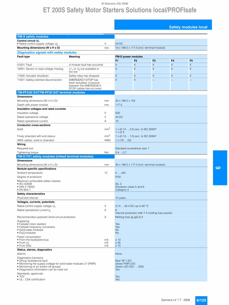
ET 200S Safety Motor Starters Solutions local/PROFIsafe
6/125Siemens LV 1 T · 2008
6
Safety modules local
PM-X safety modulesControl circuit U1• Rated control supply voltage US V 24 DC
Mounting dimensions (W x H x D) mm 15 x 196.5 x 117.5 (incl. terminal module)
Diagnostics signals with safety modulesFault type Meaning PM-D power modules
F1 F2 F3 F4 F5
01001: Fault A module fault has occurred X X X X X
10001: Sensor or load voltage missing U 1 or U2 not available or too low
X X X X X
11000: Actuator shutdown Safety relay has dropped X X X X X
11001: Safety-oriented disconnection EMERGENCY-STOP has been actuated; crossover between the EMERGENCY-STOP cables has occurred
X X -- -- --
TM-PFX30 S47/TM-PF30 S47 terminal modulesDimensions
Mounting dimensions (W x H x D) mm 30 x 196.5 x 102
Depth with power module mm 117.5
Insulation voltages and rated currents
Insulation voltage V 500
Rated operational voltage V 24 DC
Rated operational current A 10
Conductor cross-sections
Solid mm2 1 x (0.14 ... 2.5) acc. to IEC 609471 x (2.5
Finely stranded with end sleeve mm2 1 x (0.14 ... 1.5) acc. to IEC 60947
AWG cables, solid or stranded AWG 1 x (18 ... 22)
Wiring
Required tool Standard screwdriver size 1
Tightening torque Nm 0.4 ... 0.7
PM-D FX1 safety modules (infeed terminal modules)Dimensions
Mounting dimensions (W x H x D) mm 30 x 196.5 x 117.5 (incl. terminal module)
Module-specific specifications
Ambient temperature °C 0 ... +60
Degree of protection IP20
Maximum achievable safety classes• IEC 62508 SIL 3• DIN V 19250 Shutdown class 5 and 6• EN 954-1 Category 4
Safety characteristics
Proof-test interval 10 years
Voltages, currents, potentials
Rated control supply voltage Us V 21.6 ... 26.4 DC up to 60 °C
Rated operational current Ie A 6 Internal protection with 7 A melting fuse (quick)
Recommended upstream short-circuit protection A Melting fuse gL/gG 6.3
Supplying• Failsafe motor starters Yes• Failsafe frequency converters Yes• Solid-state modules No• Ex[i] modules No
Power consumption• From the backplane bus mA ≤ 10 • From U1 mA ≤ 35 • From SGx mA ≤ 15
Status, alarms, diagnostics
Alarms None
Diagnostics functions• Group fault/device fault Red "SF" LED• Monitoring the supply voltage for solid-state modules U1 (PWR) Green PWR LED• Monitoring of six switch-off groups Green LED SG1 ... SG6• Diagnostics information can be read out Yes
Standards, approvals• TÜV Yes• UL-, CSA certification Yes
© Siemens AG 2008
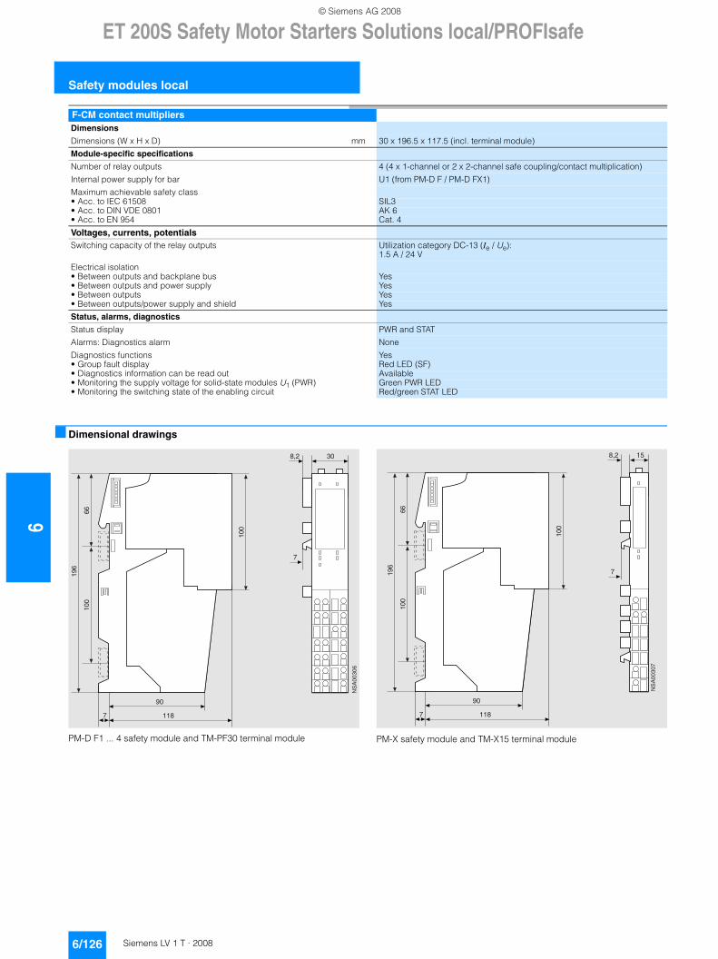
6ET 200S Safety Motor Starters Solutions local/PROFIsafe
Safety modules local
6/126 Siemens LV 1 T · 2008
■ Dimensional drawings
PM-D F1 ... 4 safety module and TM-PF30 terminal module PM-X safety module and TM-X15 terminal module
F-CM contact multipliersDimensions
Dimensions (W x H x D) mm 30 x 196.5 x 117.5 (incl. terminal module)
Module-specific specifications
Number of relay outputs 4 (4 x 1-channel or 2 x 2-channel safe coupling/contact multiplication)
Internal power supply for bar U1 (from PM-D F / PM-D FX1)
Maximum achievable safety class• Acc. to IEC 61508 SIL3• Acc. to DIN VDE 0801 AK 6• Acc. to EN 954 Cat. 4
Voltages, currents, potentialsSwitching capacity of the relay outputs Utilization category DC-13 (Ie / Ue):
1.5 A / 24 V
Electrical isolation• Between outputs and backplane bus Yes• Between outputs and power supply Yes• Between outputs Yes• Between outputs/power supply and shield Yes
Status, alarms, diagnostics
Status display PWR and STAT
Alarms: Diagnostics alarm None
Diagnostics functions Yes• Group fault display Red LED (SF)• Diagnostics information can be read out Available• Monitoring the supply voltage for solid-state modules U1 (PWR) Green PWR LED• Monitoring the switching state of the enabling circuit Red/green STAT LED
��=
@�
�@�
���
��=;
�
�
���
��
��+�����
��=
@�
�@�
���
��=;
�
�
���
��
��+�����
© Siemens AG 2008
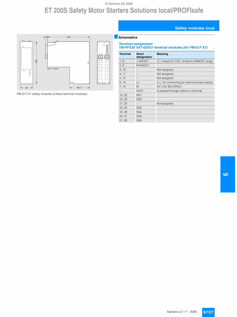
ET 200S Safety Motor Starters Solutions local/PROFIsafe
6/127Siemens LV 1 T · 2008
6
Safety modules local
PM-D F X1 safety modules (infeed terminal modules)
■ Schematics
Terminal assignment TM-PFX30 S47-G0/G1 terminal modules (for PM-D F X1)
�
�
�
��
�
�
�
� � � � �
�
� � � � � � � � � �
� � ����
Terminal Short designation
Meaning
1, 8 + IN/OUT U 1: fused 24 V DC, limited to SIMATIC range
2, 9 M IN/OUT
3, 10 -- Not assigned
4, 11 -- Not assigned
5, 12 -- Not assigned
6, 13 L+ U in: for connecting an external power supply
7, 14 M 24 V DC SELP/PELV
-- AUX1 Is passed through without a terminal
15, 22 SG1
16, 23 SG2
17, 24 -- Not assigned
18, 25 SG3
19, 26 SG4
20, 27 SG5
21, 28 SG6
© Siemens AG 2008
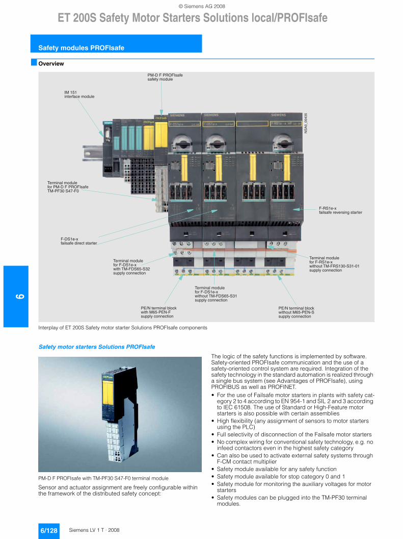
6ET 200S Safety Motor Starters Solutions local/PROFIsafe
Safety modules PROFIsafe
6/128 Siemens LV 1 T · 2008
■ Overview
Interplay of ET 200S Safety motor starter Solutions PROFIsafe components
Safety motor starters Solutions PROFIsafe
PM-D F PROFIsafe with TM-PF30 S47-F0 terminal module
Sensor and actuator assignment are freely configurable within the framework of the distributed safety concept:
The logic of the safety functions is implemented by software. Safety-oriented PROFIsafe communication and the use of a safety-oriented control system are required. Integration of the safety technology in the standard automation is realized through a single bus system (see Advantages of PROFIsafe), using PROFIBUS as well as PROFINET.• For the use of Failsafe motor starters in plants with safety cat-
egory 2 to 4 according to EN 954-1 and SIL 2 and 3 according to IEC 61508. The use of Standard or High-Feature motor starters is also possible with certain assemblies
• High flexibility (any assignment of sensors to motor starters using the PLC)
• Full selectivity of disconnection of the Failsafe motor starters• No complex wiring for conventional safety technology, e.g. no
infeed contactors even in the highest safety category• Can also be used to activate external safety systems through
F-CM contact multiplier• Safety module available for any safety function• Safety module available for stop category 0 and 1• Safety module for monitoring the auxiliary voltages for motor
starters• Safety modules can be plugged into the TM-PF30 terminal
modules.
'�����!�����!�����4�*����������'7�4*����������!��#����#����
4�*�������!��������#��������
'�����!�����!�����%7�*�4�%/540���'7�%4�������4�
%7�*�4�%/540�������������!�
% C��������!� !�#(�����7���% ��4����!��#����#����
��+�������
07����������#������!�
'�����!�����!�����4�*�������������'7�4*�����������!��#����#����
% C��������!� !�#(��������7���% �������!��#����#����
'�����!�����!�����4�/�������������'7�4/���������������!��#����#����
4�/�������!������$�����"�������
© Siemens AG 2008
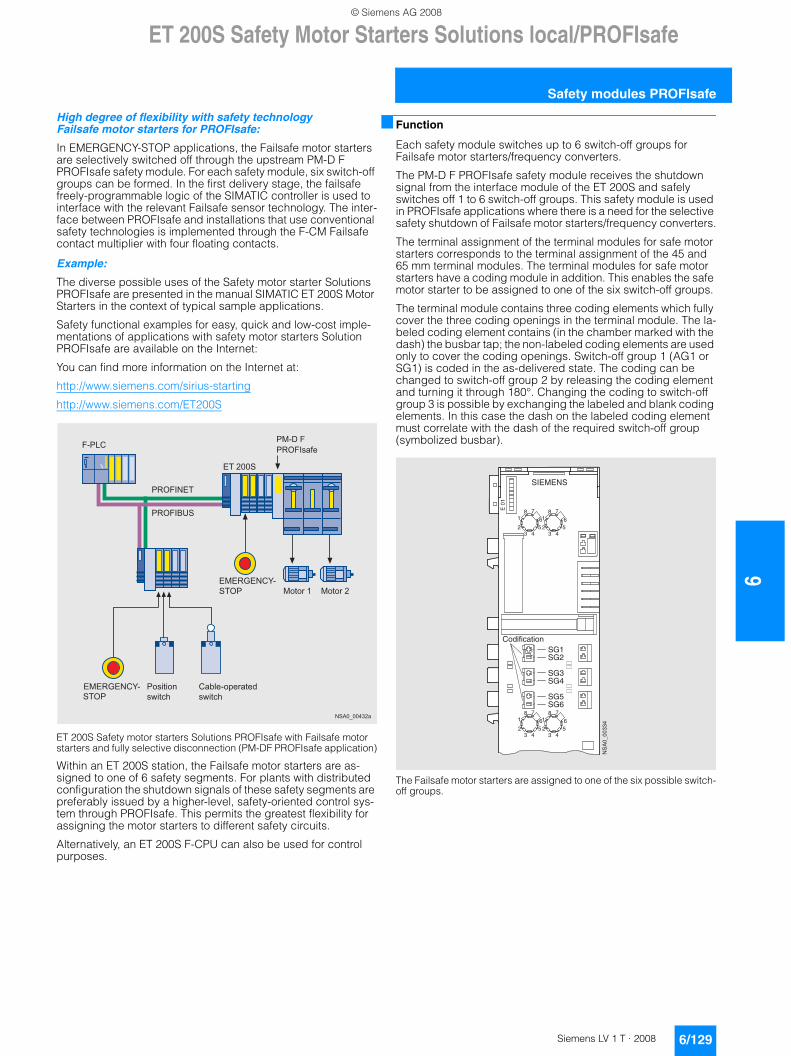
ET 200S Safety Motor Starters Solutions local/PROFIsafe
6/129Siemens LV 1 T · 2008
6
Safety modules PROFIsafe
High degree of flexibility with safety technology Failsafe motor starters for PROFIsafe:
In EMERGENCY-STOP applications, the Failsafe motor starters are selectively switched off through the upstream PM-D F PROFIsafe safety module. For each safety module, six switch-off groups can be formed. In the first delivery stage, the failsafe freely-programmable logic of the SIMATIC controller is used to interface with the relevant Failsafe sensor technology. The inter-face between PROFIsafe and installations that use conventional safety technologies is implemented through the F-CM Failsafe contact multiplier with four floating contacts.
Example:
The diverse possible uses of the Safety motor starter Solutions PROFIsafe are presented in the manual SIMATIC ET 200S Motor Starters in the context of typical sample applications.
Safety functional examples for easy, quick and low-cost imple-mentations of applications with safety motor starters Solution PROFIsafe are available on the Internet:
You can find more information on the Internet at:
http://www.siemens.com/sirius-starting
http://www.siemens.com/ET200S
ET 200S Safety motor starters Solutions PROFIsafe with Failsafe motor starters and fully selective disconnection (PM-DF PROFIsafe application)
Within an ET 200S station, the Failsafe motor starters are as-signed to one of 6 safety segments. For plants with distributed configuration the shutdown signals of these safety segments are preferably issued by a higher-level, safety-oriented control sys-tem through PROFIsafe. This permits the greatest flexibility for assigning the motor starters to different safety circuits.
Alternatively, an ET 200S F-CPU can also be used for control purposes.
■ Function
Each safety module switches up to 6 switch-off groups for Failsafe motor starters/frequency converters.
The PM-D F PROFIsafe safety module receives the shutdown signal from the interface module of the ET 200S and safely switches off 1 to 6 switch-off groups. This safety module is used in PROFIsafe applications where there is a need for the selective safety shutdown of Failsafe motor starters/frequency converters.
The terminal assignment of the terminal modules for safe motor starters corresponds to the terminal assignment of the 45 and 65 mm terminal modules. The terminal modules for safe motor starters have a coding module in addition. This enables the safe motor starter to be assigned to one of the six switch-off groups.
The terminal module contains three coding elements which fully cover the three coding openings in the terminal module. The la-beled coding element contains (in the chamber marked with the dash) the busbar tap; the non-labeled coding elements are used only to cover the coding openings. Switch-off group 1 (AG1 or SG1) is coded in the as-delivered state. The coding can be changed to switch-off group 2 by releasing the coding element and turning it through 180°. Changing the coding to switch-off group 3 is possible by exchanging the labeled and blank coding elements. In this case the dash on the labeled coding element must correlate with the dash of the required switch-off group (symbolized busbar).
The Failsafe motor starters are assigned to one of the six possible switch-off groups.
NSA0_00432a
ET 200S
PM-D F PROFIsafe
PROFIBUS
PROFINET
F-PLC
EMERGENCY-STOP
Positionswitch
Cable-operatedswitch
Motor 1 Motor 2
EMERGENCY-STOP
E 0
1
SG1SG2
SG3SG4
SG5SG6
NS
A0_
0033
465
432
18 7
65
432
18 7
65
432
18 7
65
432
18 7
SIEMENS
Codification
© Siemens AG 2008
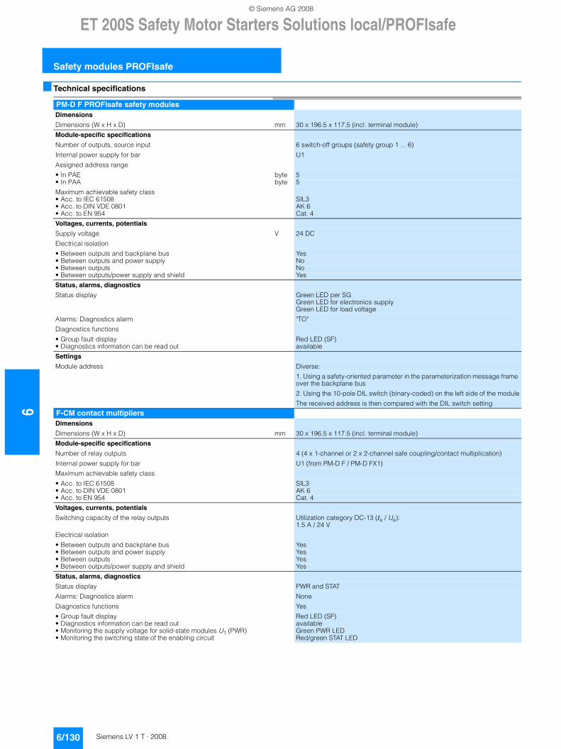
6ET 200S Safety Motor Starters Solutions local/PROFIsafe
Safety modules PROFIsafe
6/130 Siemens LV 1 T · 2008
■ Technical specifications
PM-D F PROFIsafe safety modulesDimensions
Dimensions (W x H x D) mm 30 x 196.5 x 117.5 (incl. terminal module)
Module-specific specifications
Number of outputs, source input 6 switch-off groups (safety group 1 ... 6)
Internal power supply for bar U1
Assigned address range
• In PAE byte 5 • In PAA byte 5
Maximum achievable safety class• Acc. to IEC 61508 SIL3• Acc. to DIN VDE 0801 AK 6• Acc. to EN 954 Cat. 4
Voltages, currents, potentials
Supply voltage V 24 DC
Electrical isolation
• Between outputs and backplane bus Yes• Between outputs and power supply No• Between outputs No• Between outputs/power supply and shield Yes
Status, alarms, diagnostics
Status display Green LED per SGGreen LED for electronics supplyGreen LED for load voltage
Alarms: Diagnostics alarm "TO"
Diagnostics functions
• Group fault display Red LED (SF)• Diagnostics information can be read out available
Settings
Module address Diverse:
1. Using a safety-oriented parameter in the parameterization message frame over the backplane bus
2. Using the 10-pole DIL switch (binary-coded) on the left side of the module
The received address is then compared with the DIL switch setting
F-CM contact multipliersDimensions
Dimensions (W x H x D) mm 30 x 196.5 x 117.5 (incl. terminal module)
Module-specific specifications
Number of relay outputs 4 (4 x 1-channel or 2 x 2-channel safe coupling/contact multiplication)
Internal power supply for bar U1 (from PM-D F / PM-D FX1)
Maximum achievable safety class
• Acc. to IEC 61508 SIL3• Acc. to DIN VDE 0801 AK 6• Acc. to EN 954 Cat. 4
Voltages, currents, potentials
Switching capacity of the relay outputs Utilization category DC-13 (Ie / Ue): 1.5 A / 24 V
Electrical isolation
• Between outputs and backplane bus Yes• Between outputs and power supply Yes• Between outputs Yes• Between outputs/power supply and shield Yes
Status, alarms, diagnostics
Status display PWR and STAT
Alarms: Diagnostics alarm None
Diagnostics functions Yes
• Group fault display Red LED (SF)• Diagnostics information can be read out available• Monitoring the supply voltage for solid-state modules U1 (PWR) Green PWR LED• Monitoring the switching state of the enabling circuit Red/green STAT LED
© Siemens AG 2008
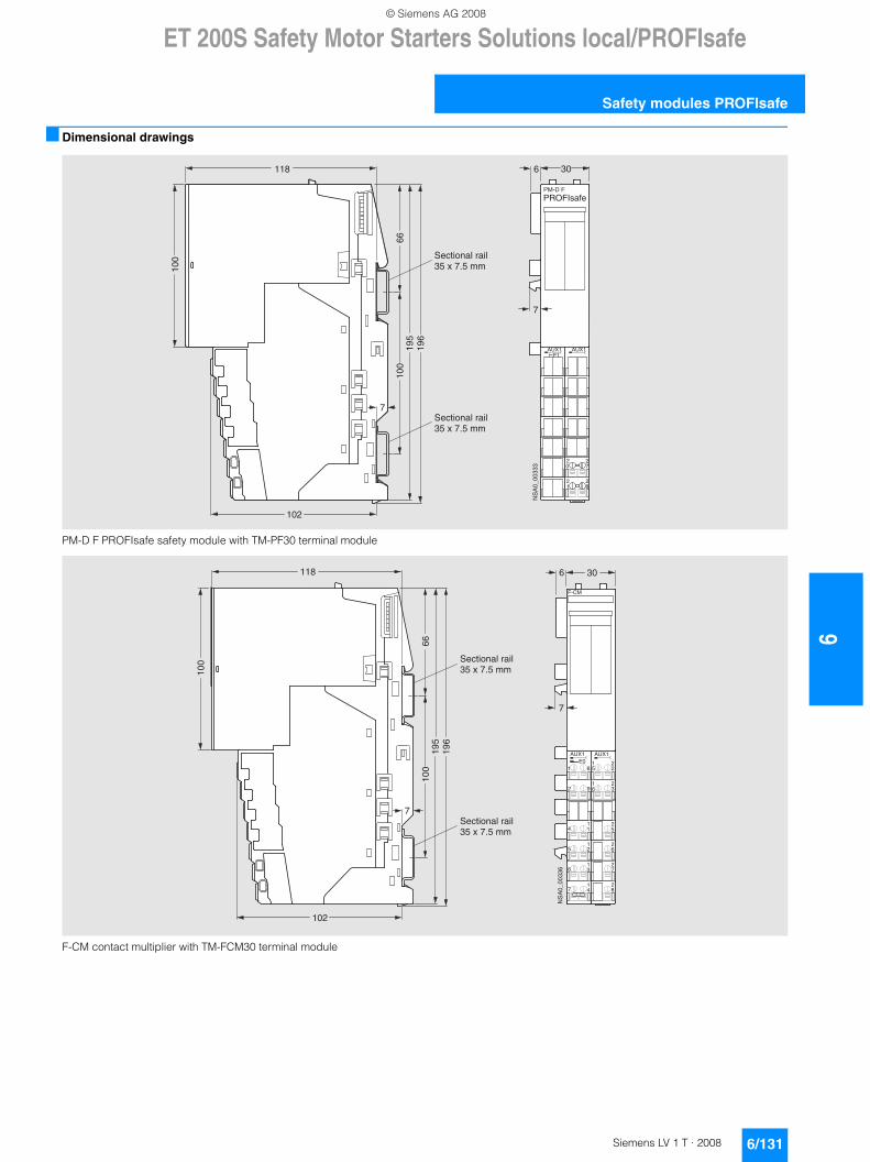
ET 200S Safety Motor Starters Solutions local/PROFIsafe
6/131Siemens LV 1 T · 2008
6
Safety modules PROFIsafe
■ Dimensional drawings
PM-D F PROFIsafe safety module with TM-PF30 terminal module
F-CM contact multiplier with TM-FCM30 terminal module
PROFIsafePM-D F
F1AUX1 AUX1
21
20
28
27
NS
A0_
0033
3
6 30
7
11810
0
6610
019
519
6
102
7
Sectional rail35 x 7.5 mm
Sectional rail35 x 7.5 mm
6 30
7
118
100
6610
019
519
6
102
7
9
17 4
6 31
5 21
4 11
2
72
82
62
52
32
61
8
AUX1
1E0
F-CM
22
AUX1
51
NS
A0_
0033
6
Sectional rail35 x 7.5 mm
Sectional rail35 x 7.5 mm
© Siemens AG 2008
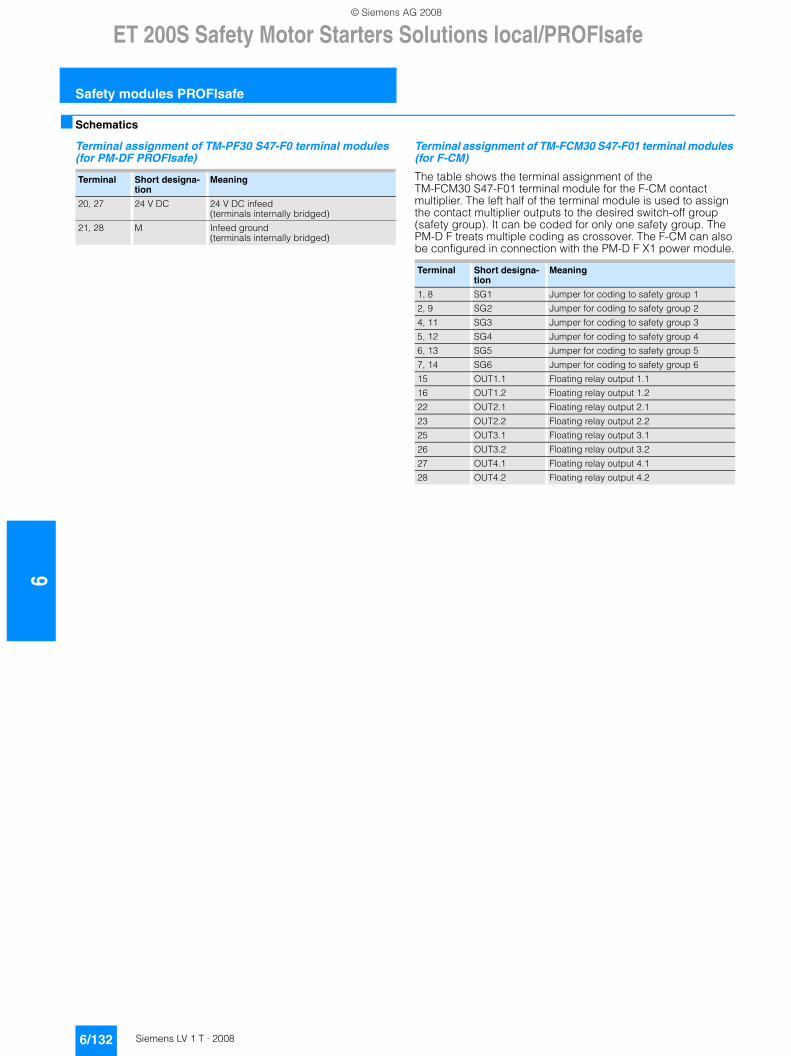
6ET 200S Safety Motor Starters Solutions local/PROFIsafe
Safety modules PROFIsafe
6/132 Siemens LV 1 T · 2008
■ Schematics
Terminal assignment of TM-PF30 S47-F0 terminal modules (for PM-DF PROFIsafe)
Terminal assignment of TM-FCM30 S47-F01 terminal modules (for F-CM)
The table shows the terminal assignment of the TM-FCM30 S47-F01 terminal module for the F-CM contact multiplier. The left half of the terminal module is used to assign the contact multiplier outputs to the desired switch-off group (safety group). It can be coded for only one safety group. The PM-D F treats multiple coding as crossover. The F-CM can also be configured in connection with the PM-D F X1 power module.
Terminal Short designa-tion
Meaning
20, 27 24 V DC 24 V DC infeed (terminals internally bridged)
21, 28 M Infeed ground (terminals internally bridged)
Terminal Short designa-tion
Meaning
1, 8 SG1 Jumper for coding to safety group 1
2, 9 SG2 Jumper for coding to safety group 2
4, 11 SG3 Jumper for coding to safety group 3
5, 12 SG4 Jumper for coding to safety group 4
6, 13 SG5 Jumper for coding to safety group 5
7, 14 SG6 Jumper for coding to safety group 6
15 OUT1.1 Floating relay output 1.1
16 OUT1.2 Floating relay output 1.2
22 OUT2.1 Floating relay output 2.1
23 OUT2.2 Floating relay output 2.2
25 OUT3.1 Floating relay output 3.1
26 OUT3.2 Floating relay output 3.2
27 OUT4.1 Floating relay output 4.1
28 OUT4.2 Floating relay output 4.2
© Siemens AG 2008
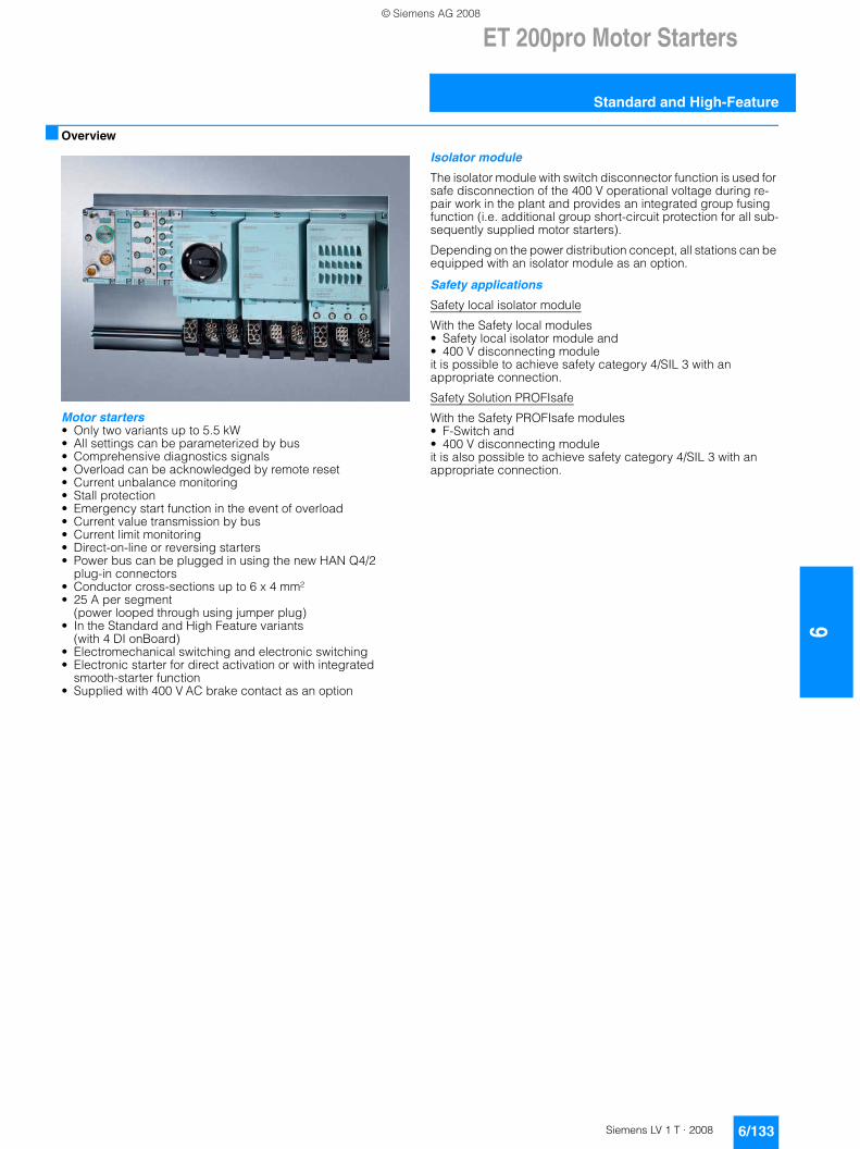
ET 200pro Motor Starters
6/133Siemens LV 1 T · 2008
6
Standard and High-Feature
■ Overview
Motor starters• Only two variants up to 5.5 kW• All settings can be parameterized by bus• Comprehensive diagnostics signals• Overload can be acknowledged by remote reset• Current unbalance monitoring• Stall protection• Emergency start function in the event of overload• Current value transmission by bus• Current limit monitoring• Direct-on-line or reversing starters• Power bus can be plugged in using the new HAN Q4/2
plug-in connectors• Conductor cross-sections up to 6 x 4 mm²• 25 A per segment
(power looped through using jumper plug)• In the Standard and High Feature variants
(with 4 DI onBoard)• Electromechanical switching and electronic switching• Electronic starter for direct activation or with integrated
smooth-starter function• Supplied with 400 V AC brake contact as an option
Isolator module
The isolator module with switch disconnector function is used for safe disconnection of the 400 V operational voltage during re-pair work in the plant and provides an integrated group fusing function (i.e. additional group short-circuit protection for all sub-sequently supplied motor starters).
Depending on the power distribution concept, all stations can be equipped with an isolator module as an option.
Safety applications
Safety local isolator module
With the Safety local modules • Safety local isolator module and • 400 V disconnecting module it is possible to achieve safety category 4/SIL 3 with an appropriate connection.
Safety Solution PROFIsafe
With the Safety PROFIsafe modules• F-Switch and • 400 V disconnecting moduleit is also possible to achieve safety category 4/SIL 3 with an appropriate connection.
© Siemens AG 2008
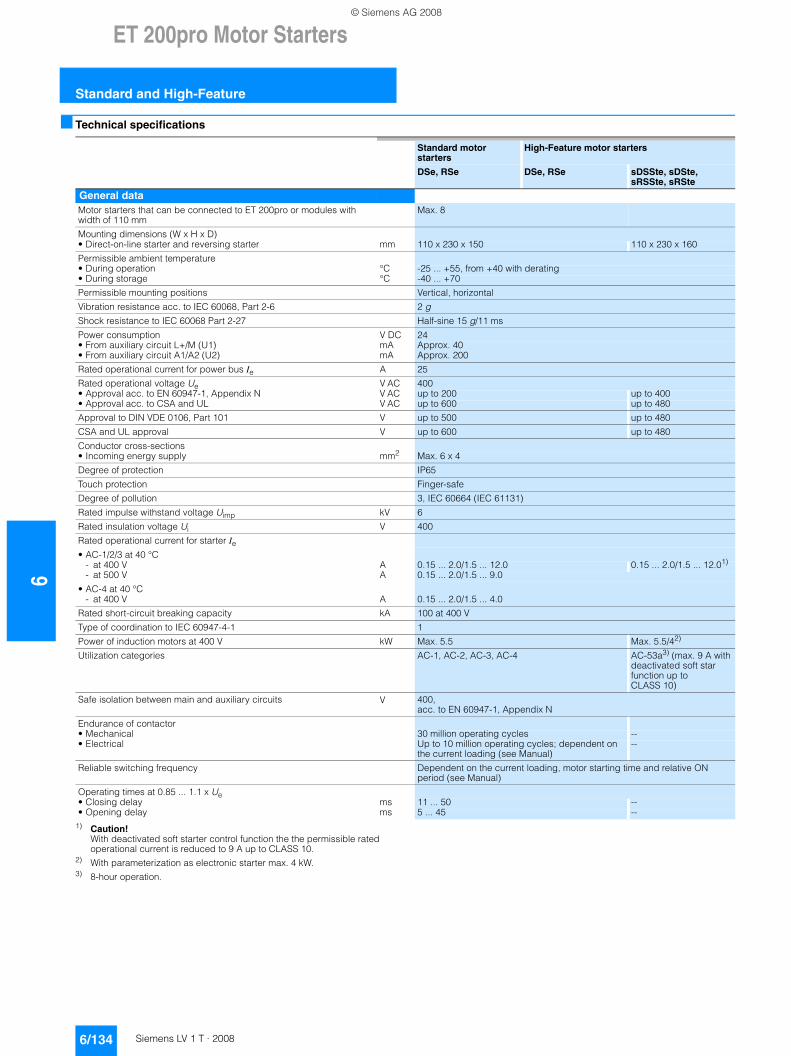
6ET 200pro Motor Starters
Standard and High-Feature
6/134 Siemens LV 1 T · 2008
■ Technical specifications
1) Caution! With deactivated soft starter control function the the permissible rated operational current is reduced to 9 A up to CLASS 10.
2) With parameterization as electronic starter max. 4 kW.3) 8-hour operation.
Standard motorstarters
High-Feature motor starters
DSe, RSe DSe, RSe sDSSte, sDSte, sRSSte, sRSte
General dataMotor starters that can be connected to ET 200pro or modules with width of 110 mm
Max. 8
Mounting dimensions (W x H x D)• Direct-on-line starter and reversing starter mm 110 x 230 x 150 110 x 230 x 160
Permissible ambient temperature• During operation °C -25 ... +55, from +40 with derating• During storage °C -40 ... +70
Permissible mounting positions Vertical, horizontal
Vibration resistance acc. to IEC 60068, Part 2-6 2 g
Shock resistance to IEC 60068 Part 2-27 Half-sine 15 g/11 ms
Power consumption V DC 24• From auxiliary circuit L+/M (U1) mA Approx. 40• From auxiliary circuit A1/A2 (U2) mA Approx. 200
Rated operational current for power bus Ie A 25
Rated operational voltage Ue V AC 400• Approval acc. to EN 60947-1, Appendix N V AC up to 200 up to 400• Approval acc. to CSA and UL V AC up to 600 up to 480
Approval to DIN VDE 0106, Part 101 V up to 500 up to 480
CSA and UL approval V up to 600 up to 480
Conductor cross-sections• Incoming energy supply mm2 Max. 6 x 4
Degree of protection IP65
Touch protection Finger-safe
Degree of pollution 3, IEC 60664 (IEC 61131)
Rated impulse withstand voltage Uimp kV 6
Rated insulation voltage Ui V 400
Rated operational current for starter Ie• AC-1/2/3 at 40 °C
- at 400 V A 0.15 ... 2.0/1.5 ... 12.0 0.15 ... 2.0/1.5 ... 12.01)
- at 500 V A 0.15 ... 2.0/1.5 ... 9.0
• AC-4 at 40 °C- at 400 V A 0.15 ... 2.0/1.5 ... 4.0
Rated short-circuit breaking capacity kA 100 at 400 V
Type of coordination to IEC 60947-4-1 1
Power of induction motors at 400 V kW Max. 5.5 Max. 5.5/42)
Utilization categories AC-1, AC-2, AC-3, AC-4 AC-53a3) (max. 9 A with deactivated soft star function up to CLASS 10)
Safe isolation between main and auxiliary circuits V 400, acc. to EN 60947-1, Appendix N
Endurance of contactor• Mechanical 30 million operating cycles --• Electrical Up to 10 million operating cycles; dependent on
the current loading (see Manual)--
Reliable switching frequency Dependent on the current loading, motor starting time and relative ON period (see Manual)
Operating times at 0.85 ... 1.1 x Ue• Closing delay ms 11 ... 50 --• Opening delay ms 5 ... 45 --
© Siemens AG 2008
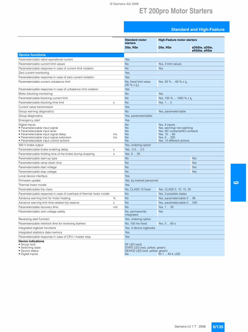
ET 200pro Motor Starters
6/135Siemens LV 1 T · 2008
6
Standard and High-Feature
Standard motor starters
High-Feature motor starters
DSe, RSe DSe, RSe sDSSte, sDSte, sRSSte, sRSte
Device functionsParameterizable rated operational current Yes
Parameterizable current limit values No Yes, 2 limit values
Parameterizable response in case of current limit violation No Yes
Zero current monitoring Yes
Parameterizable response in case of zero current violation Yes
Parameterizable current unbalance limit No, fixed limit value (30 % x Ie)
Yes, 30 % ... 60 % x Ie
Parameterizable response in case of unbalance limit violation Yes
Motor blocking monitoring No Yes
Parameterizable blocking current limit No Yes, 150 % ... 1000 % x IeParameterizable blocking time limit s No Yes, 1 ... 5
Current value transmission Yes
Group warning diagnostics No Yes, parameterizable
Group diagnostics Yes, parameterizable
Emergency start Yes
Digital inputs No Yes, 4 inputs• Parameterizable input signal No Yes, latching/ non-latching• Parameterizable input level No Yes, NC contacts/NO contacts• Parameterizable input signal delay ms No Yes, 10 ... 80• Parameterizable input signal extension ms No Yes, 0 ... 200• Parameterizable input control actions No Yes, 12 different actions
400 V brake output Yes, ordering option
Parameterizable brake enabling delay s Yes, -2.5 ... 2.5
Parameterizable holding time of the brake during stopping s Yes, 0 ... 25
Parameterizable start-up type No Yes
Parameterizable ramp-down time No Yes
Parameterizable start voltage No Yes
Parameterizable stop voltage No Yes
Local device interface Yes
Firmware update Yes, by trained personnel
Thermal motor model Yes
Parameterizable trip class No, CLASS 10 fixed Yes, CLASS 5, 10, 15, 20
Parameterizable response in case of overload of thermal motor model No Yes, 3 possible states
Advance warning limit for motor heating % No Yes, parameterizable 0 ... 95
Advance warning limit time-related trip reserve s No Yes, parameterizable 0 ... 500
Parameterizable recovery time min No Yes, 1 ... 30
Parameterizable zero voltage safety No, permanently integrated
Yes
Reversing start function Yes, ordering option
Parameterizable interlock time for reversing starters No, 150 ms fixed Yes, 0 ... 60 s
Integrated logbook functions Yes, 3 device logbooks
Integrated statistics data memory Yes
Parameterizable response in case of CPU / master stop Yes
Device indications• Group fault SF LED (red)• Switching state STATE LED (red, yellow, green)• Device status DEVICE LED (red, yellow, green)• Digital inputs No IN 1 ... IN 4, LED
© Siemens AG 2008
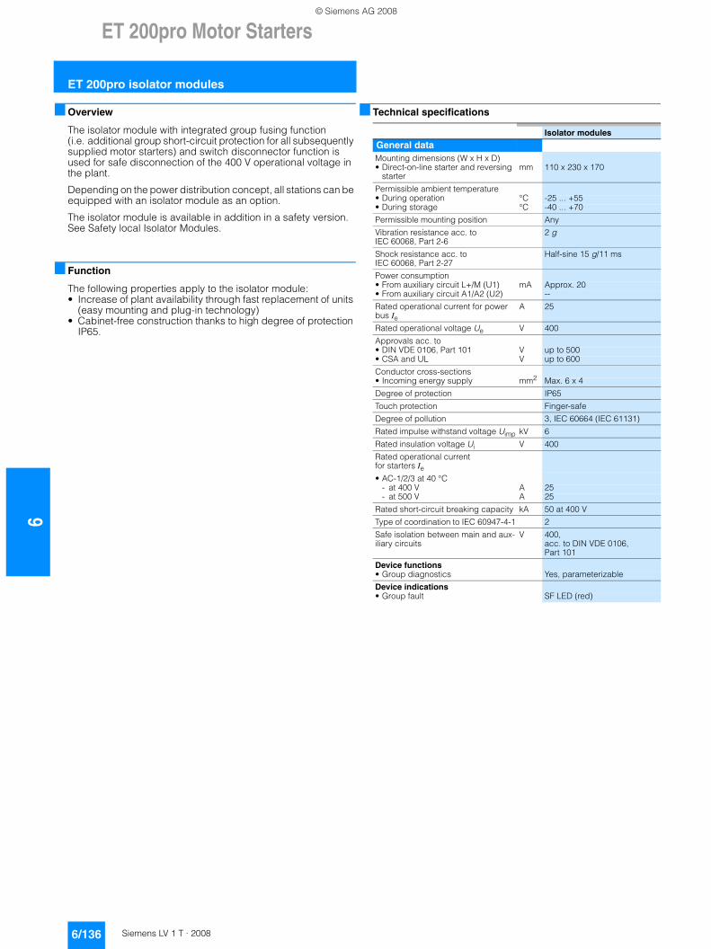
6ET 200pro Motor Starters
ET 200pro isolator modules
6/136 Siemens LV 1 T · 2008
■ Overview
The isolator module with integrated group fusing function (i.e. additional group short-circuit protection for all subsequently supplied motor starters) and switch disconnector function is used for safe disconnection of the 400 V operational voltage in the plant.
Depending on the power distribution concept, all stations can be equipped with an isolator module as an option.
The isolator module is available in addition in a safety version. See Safety local Isolator Modules.
■ Function
The following properties apply to the isolator module:• Increase of plant availability through fast replacement of units
(easy mounting and plug-in technology) • Cabinet-free construction thanks to high degree of protection
IP65.
■ Technical specifications
Isolator modules
General dataMounting dimensions (W x H x D)• Direct-on-line starter and reversing
startermm 110 x 230 x 170
Permissible ambient temperature• During operation °C -25 ... +55• During storage °C -40 ... +70
Permissible mounting position Any
Vibration resistance acc. to IEC 60068, Part 2-6
2 g
Shock resistance acc. to IEC 60068, Part 2-27
Half-sine 15 g/11 ms
Power consumption• From auxiliary circuit L+/M (U1) mA Approx. 20• From auxiliary circuit A1/A2 (U2) --
Rated operational current for power bus Ie
A 25
Rated operational voltage Ue V 400
Approvals acc. to• DIN VDE 0106, Part 101 V up to 500• CSA and UL V up to 600
Conductor cross-sections• Incoming energy supply mm2 Max. 6 x 4
Degree of protection IP65
Touch protection Finger-safe
Degree of pollution 3, IEC 60664 (IEC 61131)
Rated impulse withstand voltage Uimp kV 6
Rated insulation voltage Ui V 400
Rated operational current for starters Ie• AC-1/2/3 at 40 °C
- at 400 V A 25- at 500 V A 25
Rated short-circuit breaking capacity kA 50 at 400 V
Type of coordination to IEC 60947-4-1 2
Safe isolation between main and aux-iliary circuits
V 400, acc. to DIN VDE 0106, Part 101
Device functions• Group diagnostics Yes, parameterizable
Device indications• Group fault SF LED (red)
© Siemens AG 2008
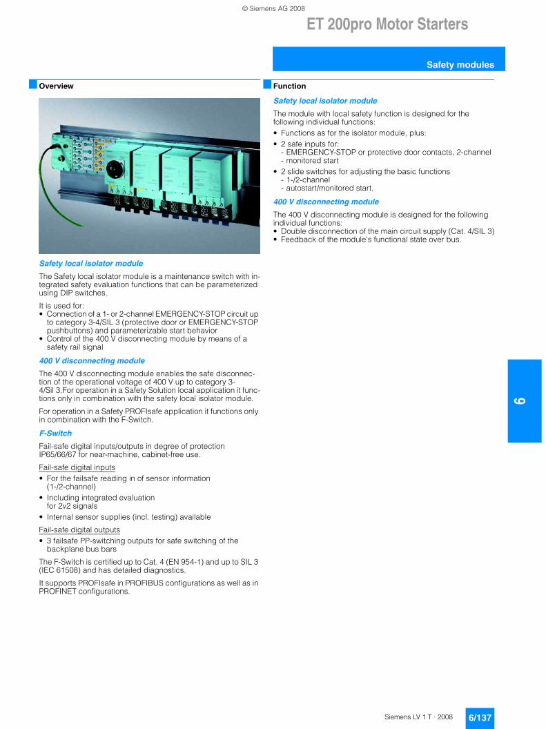
ET 200pro Motor Starters
6/137Siemens LV 1 T · 2008
6
Safety modules
■ Overview
Safety local isolator module
The Safety local isolator module is a maintenance switch with in-tegrated safety evaluation functions that can be parameterized using DIP switches.
It is used for:• Connection of a 1- or 2-channel EMERGENCY-STOP circuit up
to category 3-4/SIL 3 (protective door or EMERGENCY-STOP pushbuttons) and parameterizable start behavior
• Control of the 400 V disconnecting module by means of a safety rail signal
400 V disconnecting module
The 400 V disconnecting module enables the safe disconnec-tion of the operational voltage of 400 V up to category 3-4/Sil 3.For operation in a Safety Solution local application it func-tions only in combination with the safety local isolator module.
For operation in a Safety PROFIsafe application it functions only in combination with the F-Switch.
F-Switch
Fail-safe digital inputs/outputs in degree of protection IP65/66/67 for near-machine, cabinet-free use.
Fail-safe digital inputs• For the failsafe reading in of sensor information
(1-/2-channel)• Including integrated evaluation
for 2v2 signals• Internal sensor supplies (incl. testing) available
Fail-safe digital outputs• 3 failsafe PP-switching outputs for safe switching of the
backplane bus bars
The F-Switch is certified up to Cat. 4 (EN 954-1) and up to SIL 3 (IEC 61508) and has detailed diagnostics.
It supports PROFIsafe in PROFIBUS configurations as well as in PROFINET configurations.
■ Function
Safety local isolator module
The module with local safety function is designed for the following individual functions:• Functions as for the isolator module, plus:• 2 safe inputs for:
- EMERGENCY-STOP or protective door contacts, 2-channel- monitored start
• 2 slide switches for adjusting the basic functions - 1-/2-channel- autostart/monitored start.
400 V disconnecting module
The 400 V disconnecting module is designed for the following individual functions:• Double disconnection of the main circuit supply (Cat. 4/SIL 3)• Feedback of the module's functional state over bus.
© Siemens AG 2008
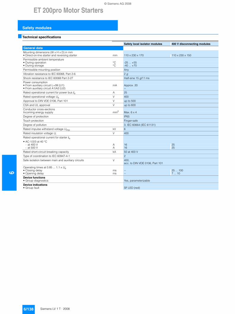
6ET 200pro Motor Starters
Safety modules
6/138 Siemens LV 1 T · 2008
■ Technical specifications
Safety local isolator modules 400 V disconnecting modules
General dataMounting dimensions (W x H x D) in mm• Direct-on-line starter and reversing starter mm 110 x 230 x 170 110 x 230 x 150
Permissible ambient temperature• During operation °C -25 ... +55• During storage °C -40 ... +70
Permissible mounting position Any
Vibration resistance to IEC 60068, Part 2-6 2 g
Shock resistance to IEC 60068 Part 2-27 Half-sine 15 g/11 ms
Power consumption• From auxiliary circuit L+/M (U1) mA Approx. 20• From auxiliary circuit A1/A2 (U2) --
Rated operational current for power bus Ie A 25
Rated operational voltage Ue V 400
Approval to DIN VDE 0106, Part 101 V up to 500
CSA and UL approval V up to 600
Conductor cross-sectionsIncoming energy supply mm2 Max. 6 x 4
Degree of protection IP65
Touch protection Finger-safe
Degree of pollution 3, IEC 60664 (IEC 61131)
Rated impulse withstand voltage Uimp kV 6
Rated insulation voltage Ui V 400
Rated operational current for starter Ie• AC-1/2/3 at 40 °C
- at 400 V A 16 25- at 500 V A 16 25
Rated short-circuit breaking capacity kA 50 at 400 V
Type of coordination to IEC 60947-4-1 2
Safe isolation between main and auxiliary circuits V 400, acc. to DIN VDE 0106, Part 101
Operating times at 0.85 ... 1.1 x Ue• Closing delay ms -- 25 ... 100• Opening delay ms -- 7 ... 10
Device functions• Group diagnostics Yes, parameterizable
Device indications• Group fault SF LED (red)
© Siemens AG 2008
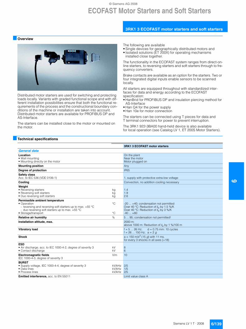
ECOFAST Motor Starters and Soft Starters
6/139Siemens LV 1 T · 2008
6
3RK1 3 ECOFAST motor starters and soft starters
■ Overview
Distributed motor starters are used for switching and protecting loads locally. Variants with graded functional scope and with dif-ferent installation possibilities ensure that both the functional re-quirements of the process and the constructional boundary con-ditions of the machine or installation are taken into account. Distributed motor starters are available for PROFIBUS DP and AS-Interface.
The starters can be installed close to the motor or mounted on the motor.
The following are available • Single devices for geographically distributed motors and • Isolated solutions (ET 200X) for operating mechanisms
installed close together.
The functionality in the ECOFAST system ranges from direct-on-line starters, to reversing starters and soft starters through to fre-quency converters.
Brake contacts are available as an option for the starters. Two or four integrated digital inputs enable sensors to be scanned locally.
All starters are equipped throughout with standardized inter-faces for data and energy according to the ECOFAST specification:• HanBrid for PROFIBUS DP and insulation piercing method for
AS-Interface• Han Q4 for the power supply• Han 10e for motor connection
The starters can be connected using T pieces for data and T terminal connectors for power to prevent interruption.
The 3RK1 922-3BA00 hand-held device is also available for local operation (see Catalog LV 1, ET 200S Motor Starters).
■ Technical specifications
3RK1 3 ECOFAST motor starters
General dataLocation On the plant• Wall mounting Near the motor• Mounting directly on the motor Motor plugged on
Mounting position Any
Degree of protection IP65
Safety classAcc. to IEC 536 (VDE 0106-1) 1, supply with protective extra-low voltage
Cooling Convection, no addition cooling necessary
Weight• Reversing starters kg 1.4• Reversing soft starters kg 1.9• Duo reversing soft starters kg 2.6
Permissible ambient temperature• Operation °C -20 ... +40; condensation not permitted
- reversing and reversing soft starters up to max. +55 °C Over 40 °C: Reduction of Ie by 1.5 %/K- duo reversing soft starters up to max. +55 °C Over 40 °C: Reduction of Ie by 3 %/K
• Storage/transport °C -40 ... +80
Relative air humidity % 5 ... 95; condensation not permitted!
Installation altitude, max. 2000 m; above 1000 m: Reduction of Ie by 1 %/100 m
Vibratory load f = 5 ... 26 Hz; d = 0.75 mm: 10 cycles f = 26 ... 150 Hz; a = 2 g
Shock a = 150 m/s2 (15 g) with 11 ms, for every 3 shocks in all axes (=18)
ESD• Air discharge, acc. to IEC 1000-4-2, degree of severity 3 kV 8• Contact discharge kV 6
Electromagnetic fields IEC 1000-4-3, degree of severity 3
V/m 10
BURST• Supply voltage, IEC 1000-4-4, degree of severity 3 kV/kHz 2/5• Data lines kV/kHz 1/5• Process lines kV/kHz 2/5
Emitted interference, acc. to EN 55011 Limit value class A
© Siemens AG 2008
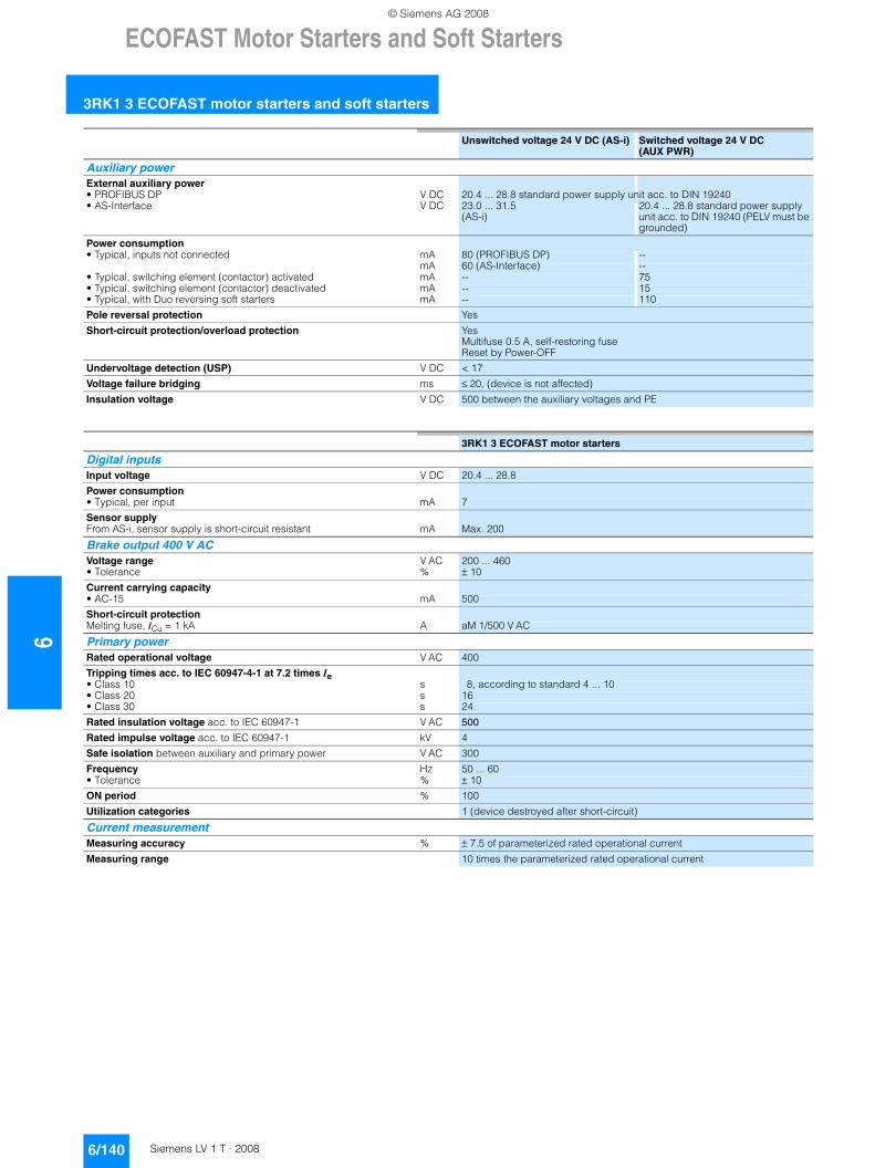
6ECOFAST Motor Starters and Soft Starters
3RK1 3 ECOFAST motor starters and soft starters
6/140 Siemens LV 1 T · 2008
Unswitched voltage 24 V DC (AS-i) Switched voltage 24 V DC (AUX PWR)
Auxiliary powerExternal auxiliary power• PROFIBUS DP V DC 20.4 ... 28.8 standard power supply unit acc. to DIN 19240• AS-Interface V DC 23.0 ... 31.5
(AS-i)20.4 ... 28.8 standard power supply unit acc. to DIN 19240 (PELV must be grounded)
Power consumption• Typical, inputs not connected mA 80 (PROFIBUS DP) --
mA 60 (AS-Interface) --• Typical, switching element (contactor) activated mA -- 75• Typical, switching element (contactor) deactivated mA -- 15• Typical, with Duo reversing soft starters mA -- 110
Pole reversal protection Yes
Short-circuit protection/overload protection Yes Multifuse 0.5 A, self-restoring fuse Reset by Power-OFF
Undervoltage detection (USP) V DC < 17
Voltage failure bridging ms ≤ 20, (device is not affected)
Insulation voltage V DC 500 between the auxiliary voltages and PE
3RK1 3 ECOFAST motor starters
Digital inputsInput voltage V DC 20.4 ... 28.8
Power consumption• Typical, per input mA 7
Sensor supplyFrom AS-i, sensor supply is short-circuit resistant mA Max. 200
Brake output 400 V ACVoltage range V AC 200 ... 460• Tolerance % ± 10
Current carrying capacity• AC-15 mA 500
Short-circuit protectionMelting fuse, ICu = 1 kA A aM 1/500 V AC
Primary powerRated operational voltage V AC 400
Tripping times acc. to IEC 60947-4-1 at 7.2 times Ie• Class 10 s 8, according to standard 4 ... 10• Class 20 s 16• Class 30 s 24
Rated insulation voltage acc. to IEC 60947-1 V AC 500
Rated impulse voltage acc. to IEC 60947-1 kV 4
Safe isolation between auxiliary and primary power V AC 300
Frequency Hz 50 ... 60• Tolerance % ± 10
ON period % 100
Utilization categories 1 (device destroyed after short-circuit)
Current measurementMeasuring accuracy % ± 7.5 of parameterized rated operational current
Measuring range 10 times the parameterized rated operational current
© Siemens AG 2008
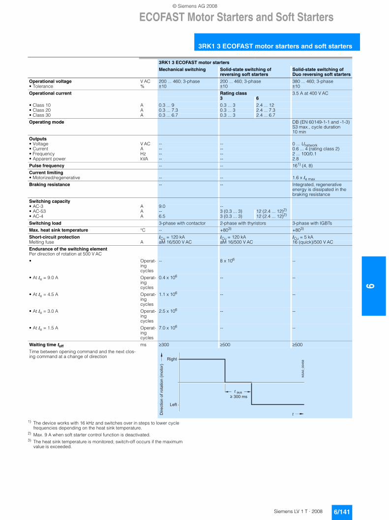
ECOFAST Motor Starters and Soft Starters
6/141Siemens LV 1 T · 2008
6
3RK1 3 ECOFAST motor starters and soft starters
1) The device works with 16 kHz and switches over in steps to lower cycle frequencies depending on the heat sink temperature.
2) Max. 9 A when soft starter control function is deactivated.3) The heat sink temperature is monitored; switch-off occurs if the maximum
value is exceeded.
3RK1 3 ECOFAST motor starters
Mechanical switching Solid-state switching of reversing soft starters
Solid-state switching of Duo reversing soft starters
Operational voltage V AC 200 ... 460; 3-phase 200 ... 460; 3-phase 380 ... 460; 3-phase• Tolerance % ±10 ±10 ±10
Operational current Rating class 3.5 A at 400 V AC3 6
• Class 10 A 0.3 ... 9 0.3 ... 3 2.4 ... 12• Class 20 A 0.3 ... 7.3 0.3 ... 3 2.4 ... 7.3• Class 30 A 0.3 ... 6.7 0.3 ... 3 2.4 ... 6.7
Operating mode DB (EN 60149-1-1 and -1-3) S3 max., cycle duration 10 min
Outputs• Voltage V AC -- -- 0 ... Unetwork• Current A -- -- 0.6 ... 4 (rating class 2)• Frequency Hz -- -- 2 ... 100/0.1• Apparent power kVA -- -- 2.8
Pulse frequency -- -- 161) (4, 8)
Current limiting• Motorized/regenerative -- -- 1.6 x Ie max
Braking resistance -- -- Integrated, regenerative energy is dissipated in the braking resistance
Switching capacity• AC-3 A 9.0 --• AC-53 A -- 3 (0.3 ... 3) 12 (2.4 ... 12)2)
• AC-4 A 6.5 3 (0.3 ... 3) 12 (2.4 ... 12)2)
Switching load 3-phase with contactor 2-phase with thyristors 3-phase with IGBTs
Max. heat sink temperature °C -- +803) +803)
Short-circuit protection ICu = 120 kA ICu = 120 kA ICu = 5 kAMelting fuse A aM 16/500 V AC aM 16/500 V AC 16 (quick)/500 V AC
Endurance of the switching element Per direction of rotation at 500 V AC
• Operat-ing cycles
-- 8 x 10⁶ --
• At Ie = 9.0 A Operat-ing cycles
0.4 x 10⁶ -- --
• At Ie = 4.5 A Operat-ing cycles
1.1 x 10⁶ -- --
• At Ie = 3.0 A Operat-ing cycles
2.5 x 10⁶ -- --
• At Ie = 1.5 A Operat-ing cycles
7.0 x 10⁶ -- --
Waiting time toff ms ≥300 ≥500 ≥500
Time between opening command and the next clos-ing command at a change of direction
Dire
ctio
n of
rota
tion
(mot
or)
Right
Left
aus
t
t ≥ 300 ms
NS
A0_
0045
8
© Siemens AG 2008
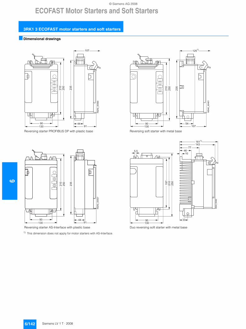
6ECOFAST Motor Starters and Soft Starters
3RK1 3 ECOFAST motor starters and soft starters
6/142 Siemens LV 1 T · 2008
■ Dimensional drawings
1) This dimension does not apply for motor starters with AS-Interface.
Reversing starter PROFIBUS DP with plastic base Reversing soft starter with metal base
Reversing starter AS-Interface with plastic base Duo reversing soft starter with metal base
4491
107
235
210
250
90130
NSA0_00460
54107
1251)
235
210
250
90130
NSA0_00461
235
210
250
9091
44
NSA0_00457
1303390
197
250
130
14377
4610
210
NSA0_00462
1611)
5,5
© Siemens AG 2008
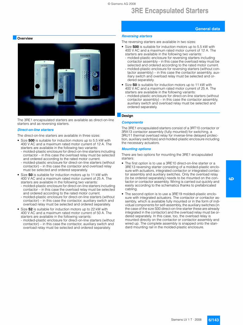
3RE Encapsulated Starters
6/143Siemens LV 1 T · 2008
6
General data
■ Overview
The 3RE1 encapsulated starters are available as direct-on-line starters and as reversing starters.
Direct-on-line starters
The direct-on-line starters are available in three sizes:• Size S00 is suitable for induction motors up to 5.5 kW with
400 V AC and a maximum rated motor current of 12 A. The starters are available in the following two variants: - molded-plastic enclosure for direct-on-line starters including
contactor – in this case the overload relay must be selected and ordered according to the rated motor current.
- molded-plastic enclosure for direct-on-line starters (without contactor) – in this case the contactor and overload relay must be selected and ordered separately.
• Size S0 is suitable for induction motors up to 11 kW with 400 V AC and a maximum rated motor current of 25 A. The starters are available in the following two variants: - molded-plastic enclosure for direct-on-line starters including
contactor – in this case the overload relay must be selected and ordered according to the rated motor current.
- molded-plastic enclosure for direct-on-line starters (without contactor) – in this case the contactor, auxiliary switch and overload relay must be selected and ordered separately.
• Size S2 is suitable for induction motors up to 22 kW with 400 V AC and a maximum rated motor current of 50 A. The starters are available in the following variants: - molded-plastic enclosure for direct-on-line starters (without
contactor) – in this case the contactor, auxiliary switch and overload relay must be selected and ordered separately.
Reversing starters
The reversing starters are available in two sizes:• Size S00 is suitable for induction motors up to 5.5 kW with
400 V AC and a maximum rated motor current of 12 A. The starters are available in the following two variants: - molded-plastic enclosure for reversing starters including
contactor assembly – in this case the overload relay must be selected and ordered according to the rated motor current.
- molded-plastic enclosure for reversing starters (without con-tactor assembly) – in this case the contactor assembly, aux-iliary switch and overload relay must be selected and or-dered separately.
• Size S0 is suitable for induction motors up to 11 kW with 400 V AC and a maximum rated motor current of 25 A. The starters are available in the following variants: - molded-plastic enclosure for direct-on-line starters (without
contactor assembly) – in this case the contactor assembly, auxiliary switch and overload relay must be selected and ordered separately.
■ Design
Components
The 3RE1 encapsulated starters consist of a 3RT10 contactor or 3RA13 contactor assembly (fully mounted) for switching, a 3RU11 thermal overload relay for inverse-time delayed protec-tion, auxiliary switch(es) and molded-plastic enclosure including the necessary actuators.
Mounting options
There are two options for mounting the 3RE1 encapsulated starters:• The first option is to use a 3RE10 direct-on-line starter or a
3RE13 reversing starter consisting of a molded-plastic enclo-sure with actuators, integrated contactor or integrated contac-tor assembly and auxiliary switches. Only the overload relay (to be ordered separately) needs to be mounted on the con-tactor or contactor assembly. Wiring is carried out quickly and easily according to the schematics thanks to prefabricated cabling.
• The second option is to use a 3RE19 molded-plastic enclo-sure with integrated actuators. The contactor or contactor as-sembly, which is available fully mounted or in the form of indi-vidual components for self-assembly, the auxiliary switches (in the case of the size S00 direct-on-line starter these are already integrated in the contactor) and the overload relay must be or-dered separately. In this case, too, the overload relay is mounted directly on the contactor or contactor assembly and wired up. The complete assembly is snapped onto the stan-dard mounting rail in the molded-plastic enclosure.
© Siemens AG 2008
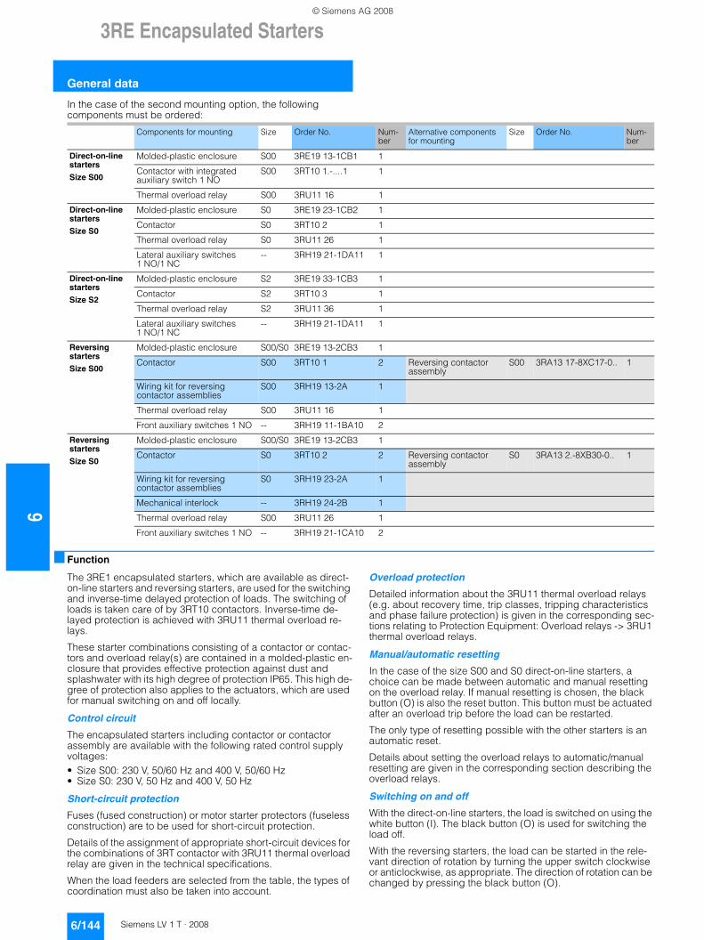
63RE Encapsulated Starters
General data
6/144 Siemens LV 1 T · 2008
In the case of the second mounting option, the following components must be ordered:
■ Function
The 3RE1 encapsulated starters, which are available as direct-on-line starters and reversing starters, are used for the switching and inverse-time delayed protection of loads. The switching of loads is taken care of by 3RT10 contactors. Inverse-time de-layed protection is achieved with 3RU11 thermal overload re-lays.
These starter combinations consisting of a contactor or contac-tors and overload relay(s) are contained in a molded-plastic en-closure that provides effective protection against dust and splashwater with its high degree of protection IP65. This high de-gree of protection also applies to the actuators, which are used for manual switching on and off locally.
Control circuit
The encapsulated starters including contactor or contactor assembly are available with the following rated control supply voltages:• Size S00: 230 V, 50/60 Hz and 400 V, 50/60 Hz• Size S0: 230 V, 50 Hz and 400 V, 50 Hz
Short-circuit protection
Fuses (fused construction) or motor starter protectors (fuseless construction) are to be used for short-circuit protection.
Details of the assignment of appropriate short-circuit devices for the combinations of 3RT contactor with 3RU11 thermal overload relay are given in the technical specifications.
When the load feeders are selected from the table, the types of coordination must also be taken into account.
Overload protection
Detailed information about the 3RU11 thermal overload relays (e.g. about recovery time, trip classes, tripping characteristics and phase failure protection) is given in the corresponding sec-tions relating to Protection Equipment: Overload relays -> 3RU1 thermal overload relays.
Manual/automatic resetting
In the case of the size S00 and S0 direct-on-line starters, a choice can be made between automatic and manual resetting on the overload relay. If manual resetting is chosen, the black button (O) is also the reset button. This button must be actuated after an overload trip before the load can be restarted.
The only type of resetting possible with the other starters is an automatic reset.
Details about setting the overload relays to automatic/manual resetting are given in the corresponding section describing the overload relays.
Switching on and off
With the direct-on-line starters, the load is switched on using the white button (I). The black button (O) is used for switching the load off.
With the reversing starters, the load can be started in the rele-vant direction of rotation by turning the upper switch clockwise or anticlockwise, as appropriate. The direction of rotation can be changed by pressing the black button (O).
Components for mounting Size Order No. Num-ber
Alternative components for mounting
Size Order No. Num-ber
Direct-on-line starters
Size S00
Molded-plastic enclosure S00 3RE19 13-1CB1 1
Contactor with integrated auxiliary switch 1 NO
S00 3RT10 1.-....1 1
Thermal overload relay S00 3RU11 16 1
Direct-on-line starters
Size S0
Molded-plastic enclosure S0 3RE19 23-1CB2 1
Contactor S0 3RT10 2 1
Thermal overload relay S0 3RU11 26 1
Lateral auxiliary switches 1 NO/1 NC
-- 3RH19 21-1DA11 1
Direct-on-line starters
Size S2
Molded-plastic enclosure S2 3RE19 33-1CB3 1
Contactor S2 3RT10 3 1
Thermal overload relay S2 3RU11 36 1
Lateral auxiliary switches 1 NO/1 NC
-- 3RH19 21-1DA11 1
Reversing starters
Size S00
Molded-plastic enclosure S00/S0 3RE19 13-2CB3 1
Contactor S00 3RT10 1 2 Reversing contactor assembly
S00 3RA13 17-8XC17-0.. 1
Wiring kit for reversing contactor assemblies
S00 3RH19 13-2A 1
Thermal overload relay S00 3RU11 16 1
Front auxiliary switches 1 NO -- 3RH19 11-1BA10 2
Reversing starters
Size S0
Molded-plastic enclosure S00/S0 3RE19 13-2CB3 1
Contactor S0 3RT10 2 2 Reversing contactor assembly
S0 3RA13 2.-8XB30-0.. 1
Wiring kit for reversing contactor assemblies
S0 3RH19 23-2A 1
Mechanical interlock -- 3RH19 24-2B 1
Thermal overload relay S00 3RU11 26 1
Front auxiliary switches 1 NO -- 3RH19 21-1CA10 2
© Siemens AG 2008
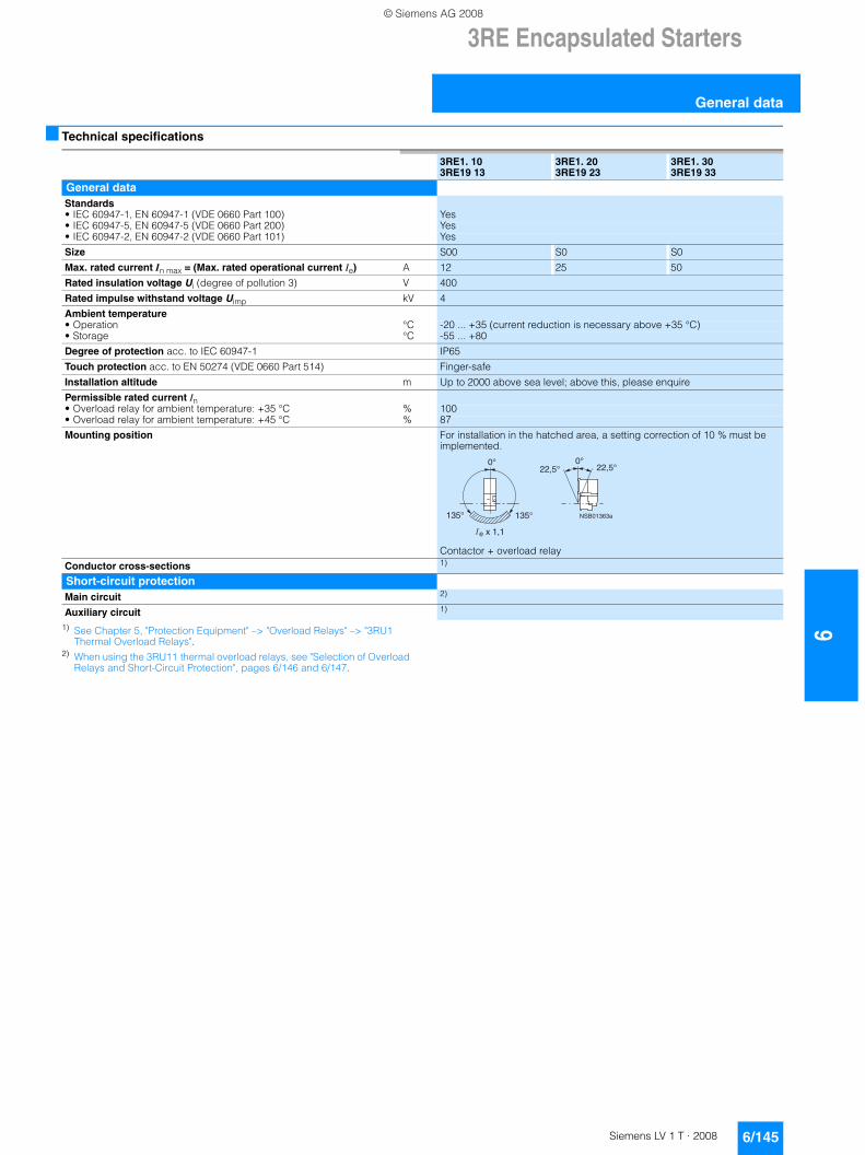
3RE Encapsulated Starters
6/145Siemens LV 1 T · 2008
6
General data
■ Technical specifications
1) See Chapter 5, "Protection Equipment" –> "Overload Relays" –> "3RU1 Thermal Overload Relays".
2) When using the 3RU11 thermal overload relays, see "Selection of Overload Relays and Short-Circuit Protection", pages 6/146 and 6/147.
3RE1. 103RE19 13
3RE1. 203RE19 23
3RE1. 303RE19 33
General dataStandards • IEC 60947-1, EN 60947-1 (VDE 0660 Part 100) Yes• IEC 60947-5, EN 60947-5 (VDE 0660 Part 200) Yes• IEC 60947-2, EN 60947-2 (VDE 0660 Part 101) Yes
Size S00 S0 S0
Max. rated current In max = (Max. rated operational current Ie) A 12 25 50
Rated insulation voltage Ui (degree of pollution 3) V 400
Rated impulse withstand voltage Uimp kV 4
Ambient temperature • Operation °C -20 ... +35 (current reduction is necessary above +35 °C)• Storage °C -55 ... +80
Degree of protection acc. to IEC 60947-1 IP65
Touch protection acc. to EN 50274 (VDE 0660 Part 514) Finger-safe
Installation altitude m Up to 2000 above sea level; above this, please enquire
Permissible rated current In • Overload relay for ambient temperature: +35 °C % 100• Overload relay for ambient temperature: +45 °C % 87
Mounting position For installation in the hatched area, a setting correction of 10 % must be implemented.
Contactor + overload relay
Conductor cross-sections 1)
Short-circuit protectionMain circuit 2)
Auxiliary circuit 1)
NSB01363a135°
0°22,5° 22,5°
135°
� e
0°
x 1,1
© Siemens AG 2008
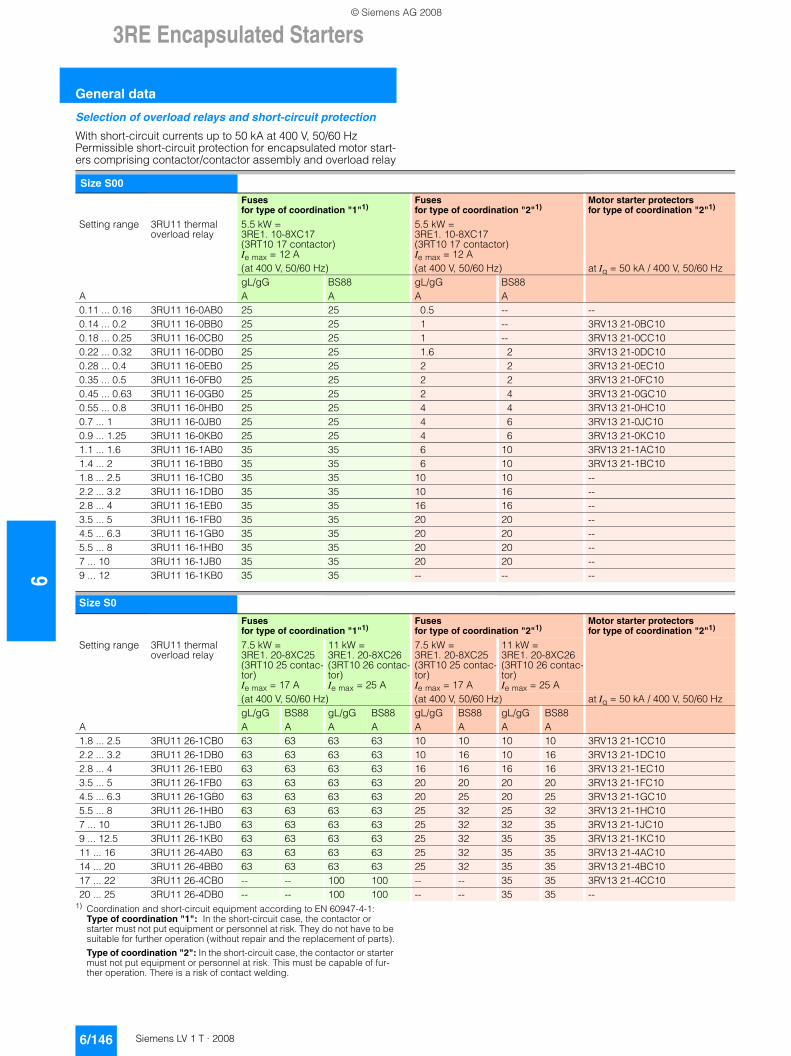
63RE Encapsulated Starters
General data
6/146 Siemens LV 1 T · 2008
Selection of overload relays and short-circuit protection
With short-circuit currents up to 50 kA at 400 V, 50/60 Hz Permissible short-circuit protection for encapsulated motor start-ers comprising contactor/contactor assembly and overload relay
1) Coordination and short-circuit equipment according to EN 60947-4-1:Type of coordination "1": In the short-circuit case, the contactor or starter must not put equipment or personnel at risk. They do not have to be suitable for further operation (without repair and the replacement of parts).
Type of coordination "2": In the short-circuit case, the contactor or starter must not put equipment or personnel at risk. This must be capable of fur-ther operation. There is a risk of contact welding.
Size S00
Fuses for type of coordination "1"1)
Fuses for type of coordination "2"1)
Motor starter protectors for type of coordination "2"1)
Setting range 3RU11 thermal overload relay
5.5 kW = 3RE1. 10-8XC17(3RT10 17 contactor)Ie max = 12 A (at 400 V, 50/60 Hz)
5.5 kW = 3RE1. 10-8XC17(3RT10 17 contactor)Ie max = 12 A (at 400 V, 50/60 Hz) at Iq = 50 kA / 400 V, 50/60 Hz
AgL/gGA
BS88A
gL/gGA
BS88A
0.11 ... 0.16 3RU11 16-0AB0 25 25 0.5 -- --0.14 ... 0.2 3RU11 16-0BB0 25 25 1 -- 3RV13 21-0BC100.18 ... 0.25 3RU11 16-0CB0 25 25 1 -- 3RV13 21-0CC100.22 ... 0.32 3RU11 16-0DB0 25 25 1.6 2 3RV13 21-0DC100.28 ... 0.4 3RU11 16-0EB0 25 25 2 2 3RV13 21-0EC100.35 ... 0.5 3RU11 16-0FB0 25 25 2 2 3RV13 21-0FC100.45 ... 0.63 3RU11 16-0GB0 25 25 2 4 3RV13 21-0GC100.55 ... 0.8 3RU11 16-0HB0 25 25 4 4 3RV13 21-0HC100.7 ... 1 3RU11 16-0JB0 25 25 4 6 3RV13 21-0JC100.9 ... 1.25 3RU11 16-0KB0 25 25 4 6 3RV13 21-0KC101.1 ... 1.6 3RU11 16-1AB0 35 35 6 10 3RV13 21-1AC101.4 ... 2 3RU11 16-1BB0 35 35 6 10 3RV13 21-1BC101.8 ... 2.5 3RU11 16-1CB0 35 35 10 10 --2.2 ... 3.2 3RU11 16-1DB0 35 35 10 16 --2.8 ... 4 3RU11 16-1EB0 35 35 16 16 --3.5 ... 5 3RU11 16-1FB0 35 35 20 20 --4.5 ... 6.3 3RU11 16-1GB0 35 35 20 20 --5.5 ... 8 3RU11 16-1HB0 35 35 20 20 --7 ... 10 3RU11 16-1JB0 35 35 20 20 --9 ... 12 3RU11 16-1KB0 35 35 -- -- --
Size S0
Fuses for type of coordination "1"1)
Fuses for type of coordination "2"1)
Motor starter protectors for type of coordination "2"1)
Setting range 3RU11 thermal overload relay
7.5 kW = 3RE1. 20-8XC25(3RT10 25 contac-tor)Ie max = 17 A
11 kW = 3RE1. 20-8XC26(3RT10 26 contac-tor)Ie max = 25 A
7.5 kW = 3RE1. 20-8XC25(3RT10 25 contac-tor)Ie max = 17 A
11 kW = 3RE1. 20-8XC26(3RT10 26 contac-tor)Ie max = 25 A
(at 400 V, 50/60 Hz) (at 400 V, 50/60 Hz) at Iq = 50 kA / 400 V, 50/60 Hz
AgL/gGA
BS88A
gL/gGA
BS88A
gL/gGA
BS88A
gL/gGA
BS88A
1.8 ... 2.5 3RU11 26-1CB0 63 63 63 63 10 10 10 10 3RV13 21-1CC102.2 ... 3.2 3RU11 26-1DB0 63 63 63 63 10 16 10 16 3RV13 21-1DC102.8 ... 4 3RU11 26-1EB0 63 63 63 63 16 16 16 16 3RV13 21-1EC103.5 ... 5 3RU11 26-1FB0 63 63 63 63 20 20 20 20 3RV13 21-1FC104.5 ... 6.3 3RU11 26-1GB0 63 63 63 63 20 25 20 25 3RV13 21-1GC105.5 ... 8 3RU11 26-1HB0 63 63 63 63 25 32 25 32 3RV13 21-1HC107 ... 10 3RU11 26-1JB0 63 63 63 63 25 32 32 35 3RV13 21-1JC109 ... 12.5 3RU11 26-1KB0 63 63 63 63 25 32 35 35 3RV13 21-1KC1011 ... 16 3RU11 26-4AB0 63 63 63 63 25 32 35 35 3RV13 21-4AC1014 ... 20 3RU11 26-4BB0 63 63 63 63 25 32 35 35 3RV13 21-4BC1017 ... 22 3RU11 26-4CB0 -- -- 100 100 -- -- 35 35 3RV13 21-4CC1020 ... 25 3RU11 26-4DB0 -- -- 100 100 -- -- 35 35 --
© Siemens AG 2008
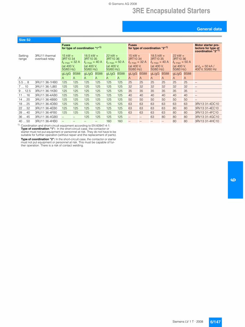
3RE Encapsulated Starters
6/147Siemens LV 1 T · 2008
6
General data
1) Coordination and short-circuit equipment according to EN 60947-4-1:Type of coordination "1": In the short-circuit case, the contactor or starter must not put equipment or personnel at risk. They do not have to be suitable for further operation (without repair and the replacement of parts).
Type of coordination "2": In the short-circuit case, the contactor or starter must not put equipment or personnel at risk. This must be capable of fur-ther operation. There is a risk of contact welding.
Size S2
Fuses for type of coordination "1"1)
Fuses for type of coordination "2"1)
Motor starter pro-tectors for type of coordination "2"1)
Setting range
3RU11 thermal overload relay
15 kW = 3RT10 34Ie max = 32 A(at 400 V, 50/60 Hz)
18.5 kW = 3RT10 35Ie max = 40 A(at 400 V, 50/60 Hz)
22 kW = 3RT10 36Ie max = 50 A(at 400 V, 50/60 Hz)
15 kW = 3RT10 34Ie max = 32 A(at 400 V, 50/60 Hz)
18.5 kW = 3RT10 35Ie max = 40 A(at 400 V, 50/60 Hz)
22 kW = 3RT10 36Ie max = 50 A(at 400 V, 50/60 Hz)
at Iq = 50 kA / 400 V, 50/60 Hz
AgL/gGA
BS88A
gL/gGA
BS88A
gL/gGA
BS88A
gL/gGA
BS88A
gL/gGA
BS88A
gL/gGA
BS88A
5.5 ... 8 3RU11 36-1HB0 125 125 125 125 125 125 25 25 25 25 25 25 --7 ... 10 3RU11 36-1JB0 125 125 125 125 125 125 32 32 32 32 32 32 --9 ... 12.5 3RU11 36-1KB0 125 125 125 125 125 125 35 35 35 35 35 35 --11 ... 16 3RU11 36-4AB0 125 125 125 125 125 125 40 40 40 40 40 40 --14 ... 20 3RU11 36-4BB0 125 125 125 125 125 125 50 50 50 50 50 50 --18 ... 25 3RU11 36-4DB0 125 125 125 125 125 125 63 63 63 63 63 63 3RV13 31-4DC1022 ... 32 3RU11 36-4EB0 125 125 125 125 125 125 63 63 63 63 80 80 3RV13 31-4EC1028 ... 40 3RU11 36-4FB0 125 125 125 125 125 125 63 63 63 63 80 80 3RV13 31-4FC1036 ... 45 3RU11 36-4GB0 -- -- 125 125 125 125 -- -- 63 80 80 80 3RV13 31-4GC1040 ... 50 3RU11 36-4HB0 -- -- -- -- 160 160 -- -- -- -- 80 80 3RV13 31-4HC10
© Siemens AG 2008
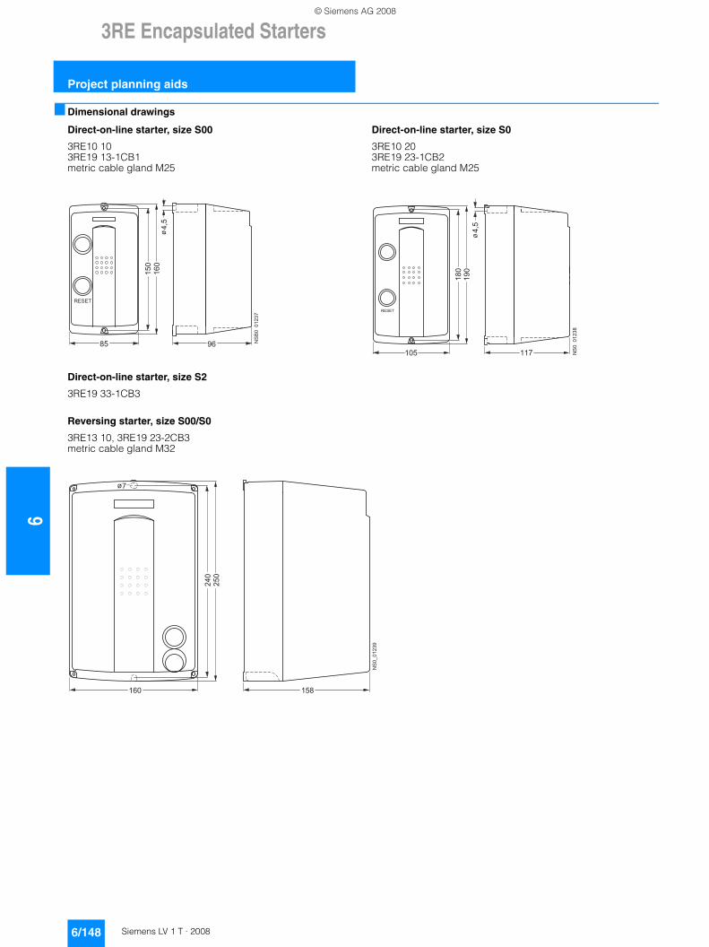
63RE Encapsulated Starters
Project planning aids
6/148 Siemens LV 1 T · 2008
■ Dimensional drawings
Direct-on-line starter, size S00
3RE10 10 3RE19 13-1CB1metric cable gland M25
Direct-on-line starter, size S2
3RE19 33-1CB3
Reversing starter, size S00/S0
3RE13 10, 3RE19 23-2CB3 metric cable gland M32
Direct-on-line starter, size S0
3RE10 20 3RE19 23-1CB2 metric cable gland M25
������
��
��
���
���
����
��
��
��
��
���
�
���
���
����
������
��
��
���
���
��
��
��
© Siemens AG 2008
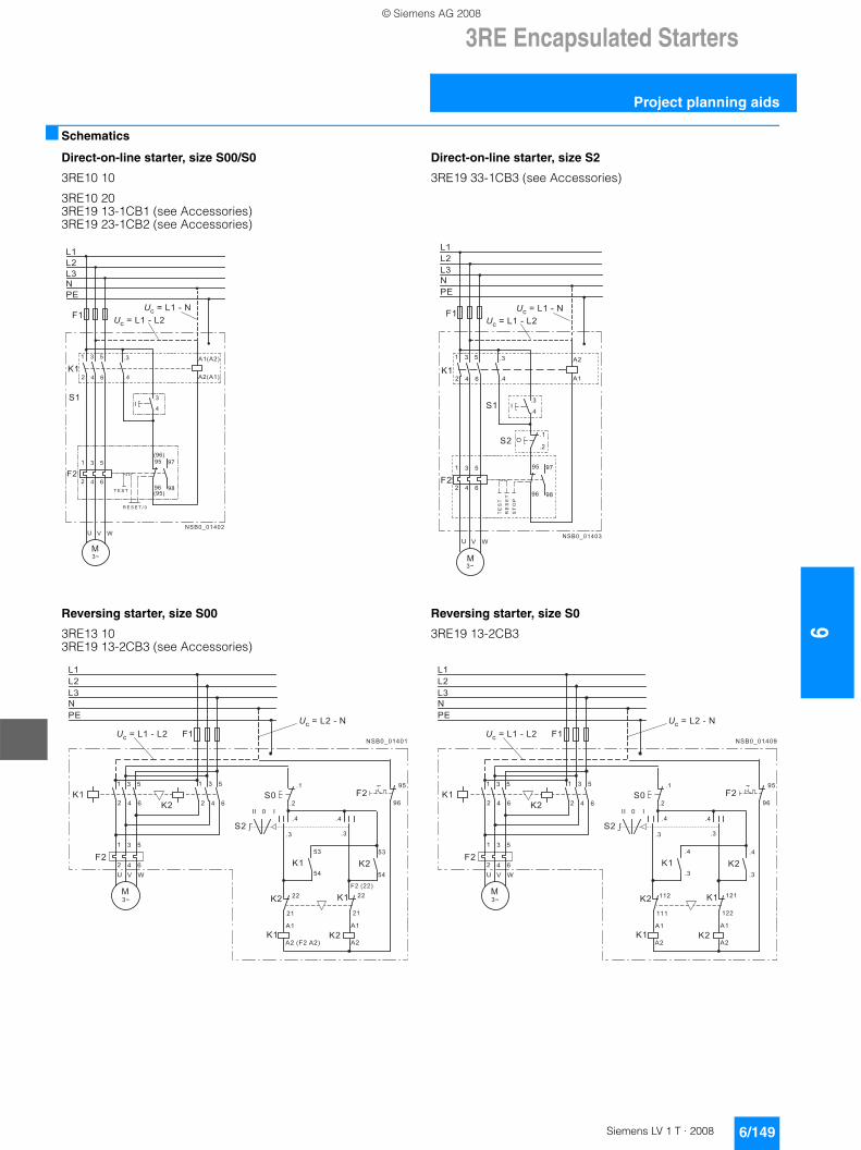
3RE Encapsulated Starters
6/149Siemens LV 1 T · 2008
6
Project planning aids
■ Schematics
Direct-on-line starter, size S00/S0
3RE10 10
3RE10 20 3RE19 13-1CB1 (see Accessories) 3RE19 23-1CB2 (see Accessories)
Reversing starter, size S00
3RE13 10 3RE19 13-2CB3 (see Accessories)
Direct-on-line starter, size S2
3RE19 33-1CB3 (see Accessories)
Reversing starter, size S0
3RE19 13-2CB3
� �
� � �
� � �
� �
� � �
� � �
� �
� �
� �
� �
� �
� �
� �
� �
� �� � � �
� � � � � � �
�� �
���
� � �
� � �
� �
� �
� �
�
� �
� � �
� � �
� �
� � � � � � � � �
�!" # " � � " $ " �
�!" # " � � " $ " � �
��
��
��
��
��
��
���
�
��
�
�
� � �
� � �
� � �
� � �
� � �
� � �
��
��
��
��
��
��
����������
��
��
��
��
��
��
��
��
��
�� ��
����
��
��
��
��
��
��
��
�����������
��
��
����������
�����������
������������
�������
��
� � �
� � �
��
��
��
��
��
��
���
��
!���
� "
�
��
���
�
� � �
� � �
"��
����
��
��
��
�
��
��
��
�#
�$
��
����������
�����������
������������
��
��
��
��
��
��
���
��
��
�
��
� � �
� � �
� � �
� � �
� � �
� � �
��
��
��
��
��
��
��
���
���
��
���
���
��
��
��
��
�� ��
����
��
��
��
��
��
��
��
�����������
��
��
����������
�����������
������������
© Siemens AG 2008
63RE Encapsulated Starters
Project planning aids
6/150 Siemens LV 1 T · 2008
7
© Siemens AG 2008