logix5000 control systems: connecting panelview … 3 6 5 8 7 panelview plus terminal with built-in...
TRANSCRIPT

Logix5000 Control Systems: Connect a PanelView Plus Terminal over an EtherNet/IP NetworkCatalog Numbers Logix5000 Controllers, 2711P PanelView Plus Terminals
Quick Start

Important User Information
Solid-state equipment has operational characteristics differing from those of electromechanical equipment. Safety Guidelines for the Application, Installation and Maintenance of Solid State Controls (publication SGI-1.1 available from your local Rockwell Automation sales office or online at http://www.rockwellautomation.com/literature/) describes some important differences between solid-state equipment and hard-wired electromechanical devices. Because of this difference, and also because of the wide variety of uses for solid-state equipment, all persons responsible for applying this equipment must satisfy themselves that each intended application of this equipment is acceptable.
In no event will Rockwell Automation, Inc. be responsible or liable for indirect or consequential damages resulting from the use or application of this equipment.
The examples and diagrams in this manual are included solely for illustrative purposes. Because of the many variables and requirements associated with any particular installation, Rockwell Automation, Inc. cannot assume responsibility or liability for actual use based on the examples and diagrams.
No patent liability is assumed by Rockwell Automation, Inc. with respect to use of information, circuits, equipment, or software described in this manual.
Reproduction of the contents of this manual, in whole or in part, without written permission of Rockwell Automation, Inc., is prohibited.
Throughout this manual, when necessary, we use notes to make you aware of safety considerations.
Allen-Bradley, Compact I/O, CompactLogix, FactoryTalk, Integrated Architecture, Logix5000, PanelView, POINT I/O, Rockwell Software, Rockwell Automation, RSLinx, RSLogix, RSNetWorx, Stratix 6000, and TechConnect are trademarks of Rockwell Automation, Inc.
Trademarks not belonging to Rockwell Automation are property of their respective companies.
WARNING: Identifies information about practices or circumstances that can cause an explosion in a hazardous environment, which may lead to personal injury or death, property damage, or economic loss.
ATTENTION: Identifies information about practices or circumstances that can lead to personal injury or death, property damage, or economic loss. Attentions help you identify a hazard, avoid a hazard, and recognize the consequence.
SHOCK HAZARD: Labels may be on or inside the equipment, for example, a drive or motor, to alert people that dangerous voltage may be present.
BURN HAZARD: Labels may be on or inside the equipment, for example, a drive or motor, to alert people that surfaces may reach dangerous temperatures.
IMPORTANT Identifies information that is critical for successful application and understanding of the product.
Table of Contents
Preface Before Using This Publication . . . . . . . . . . . . . . . . . . . . . . . . . . . . . . . . . . . . . . 5Other Logix5000 Control System Quick Starts . . . . . . . . . . . . . . . . . . . . . . . 8Use Each Chapter . . . . . . . . . . . . . . . . . . . . . . . . . . . . . . . . . . . . . . . . . . . . . . . . . . 8Where to Start . . . . . . . . . . . . . . . . . . . . . . . . . . . . . . . . . . . . . . . . . . . . . . . . . . . . . 9How Hardware Is Connected . . . . . . . . . . . . . . . . . . . . . . . . . . . . . . . . . . . . . 10Required Software . . . . . . . . . . . . . . . . . . . . . . . . . . . . . . . . . . . . . . . . . . . . . . . 10Parts List . . . . . . . . . . . . . . . . . . . . . . . . . . . . . . . . . . . . . . . . . . . . . . . . . . . . . . . . 11Additional Resources . . . . . . . . . . . . . . . . . . . . . . . . . . . . . . . . . . . . . . . . . . . . . 11
Chapter 1Prepare the PanelView Plus Terminal Hardware
Before You Begin . . . . . . . . . . . . . . . . . . . . . . . . . . . . . . . . . . . . . . . . . . . . . . . . 13What You Need . . . . . . . . . . . . . . . . . . . . . . . . . . . . . . . . . . . . . . . . . . . . . . . . . 13Follow These Steps . . . . . . . . . . . . . . . . . . . . . . . . . . . . . . . . . . . . . . . . . . . . . . . 14Mount the PanelView Plus Terminal . . . . . . . . . . . . . . . . . . . . . . . . . . . . . . 14Connect the Power Supply . . . . . . . . . . . . . . . . . . . . . . . . . . . . . . . . . . . . . . . 15Connect the PanelView Plus Terminal to the EtherNet/IP Network . . . . . . . . . . . . . . . . . . . . . . . . . . . . . . . . . . . . . . . . . . . . 16Assign an IP Address to the PanelView Plus Terminal . . . . . . . . . . . . . . . 17Additional Resources . . . . . . . . . . . . . . . . . . . . . . . . . . . . . . . . . . . . . . . . . . . . . 19
Chapter 2Create a PanelView Plus Application Before You Begin . . . . . . . . . . . . . . . . . . . . . . . . . . . . . . . . . . . . . . . . . . . . . . . . 21
What You Need . . . . . . . . . . . . . . . . . . . . . . . . . . . . . . . . . . . . . . . . . . . . . . . . . 22Follow These Steps . . . . . . . . . . . . . . . . . . . . . . . . . . . . . . . . . . . . . . . . . . . . . . . 23Install FactoryTalk View Studio Software . . . . . . . . . . . . . . . . . . . . . . . . . . 24Install RSLinx Enterprise Software . . . . . . . . . . . . . . . . . . . . . . . . . . . . . . . . 28Create a New Application . . . . . . . . . . . . . . . . . . . . . . . . . . . . . . . . . . . . . . . . 30Create an RSLinx Enterprise Configuration in FactoryTalk View Machine Edition. . . . . . . . . . . . . . . . . . . . . . . . . . . . . . . . 31Create a Device Shortcut to the Controller . . . . . . . . . . . . . . . . . . . . . . . . . 33Create the OB16_Light Indicator . . . . . . . . . . . . . . . . . . . . . . . . . . . . . . . . . 34Create a Push Button. . . . . . . . . . . . . . . . . . . . . . . . . . . . . . . . . . . . . . . . . . . . . 38Test the Indicator and Push Button. . . . . . . . . . . . . . . . . . . . . . . . . . . . . . . . 40Add a Goto Configuration Mode Button . . . . . . . . . . . . . . . . . . . . . . . . . . 43Assign Function Keys. . . . . . . . . . . . . . . . . . . . . . . . . . . . . . . . . . . . . . . . . . . . . 45Assign an Initial Screen . . . . . . . . . . . . . . . . . . . . . . . . . . . . . . . . . . . . . . . . . . . 46Transfer to PanelView Plus Terminal . . . . . . . . . . . . . . . . . . . . . . . . . . . . . . 47Test the Application on the PanelView Plus Terminal. . . . . . . . . . . . . . . 49Additional Resources . . . . . . . . . . . . . . . . . . . . . . . . . . . . . . . . . . . . . . . . . . . . . 50
Index . . . . . . . . . . . . . . . . . . . . . . . . . . . . . . . . . . . . . . . . . . . . . . . . . . . . . . . . . . . . . . . . . . 51
Rockwell Automation Publication IASIMP-QS033A-EN-P - March 2012 3
Table of Contents
Notes:
4 Rockwell Automation Publication IASIMP-QS033A-EN-P - March 2012
Preface
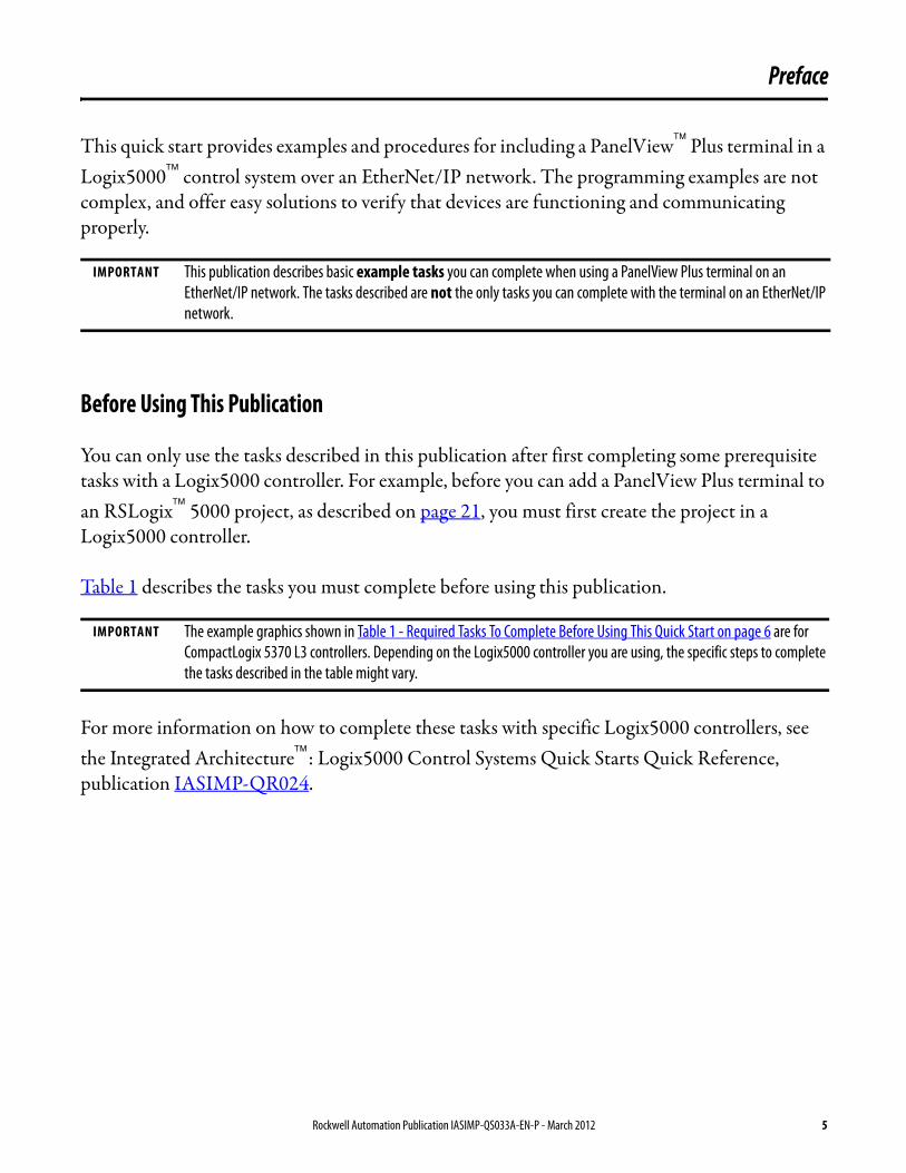
This quick start provides examples and procedures for including a PanelView Plus terminal in a Logix5000 control system over an EtherNet/IP network. The programming examples are not complex, and offer easy solutions to verify that devices are functioning and communicating properly.
Before Using This Publication
You can only use the tasks described in this publication after first completing some prerequisite tasks with a Logix5000 controller. For example, before you can add a PanelView Plus terminal to an RSLogix 5000 project, as described on page 21, you must first create the project in a Logix5000 controller.
Table 1 describes the tasks you must complete before using this publication.
For more information on how to complete these tasks with specific Logix5000 controllers, see the Integrated Architecture: Logix5000 Control Systems Quick Starts Quick Reference, publication IASIMP-QR024.
IMPORTANT This publication describes basic example tasks you can complete when using a PanelView Plus terminal on an EtherNet/IP network. The tasks described are not the only tasks you can complete with the terminal on an EtherNet/IP network.
IMPORTANT The example graphics shown in Table 1 - Required Tasks To Complete Before Using This Quick Start on page 6 are for CompactLogix 5370 L3 controllers. Depending on the Logix5000 controller you are using, the specific steps to complete the tasks described in the table might vary.
Rockwell Automation Publication IASIMP-QS033A-EN-P - March 2012 5
Preface
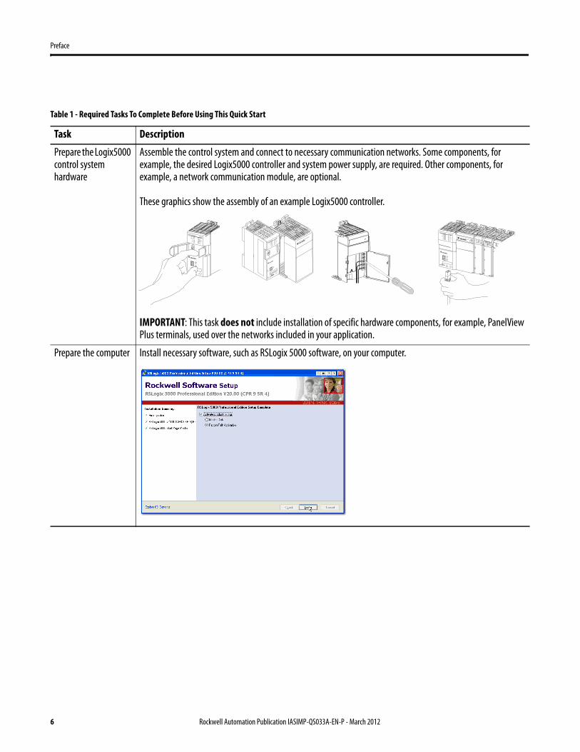
Table 1 - Required Tasks To Complete Before Using This Quick Start
Task Description
Prepare the Logix5000 control system hardware
Assemble the control system and connect to necessary communication networks. Some components, for example, the desired Logix5000 controller and system power supply, are required. Other components, for example, a network communication module, are optional.
These graphics show the assembly of an example Logix5000 controller.
IMPORTANT: This task does not include installation of specific hardware components, for example, PanelView Plus terminals, used over the networks included in your application.
Prepare the computer Install necessary software, such as RSLogix 5000 software, on your computer.
2 (Rear)
1 (Front)
6 Rockwell Automation Publication IASIMP-QS033A-EN-P - March 2012
Preface
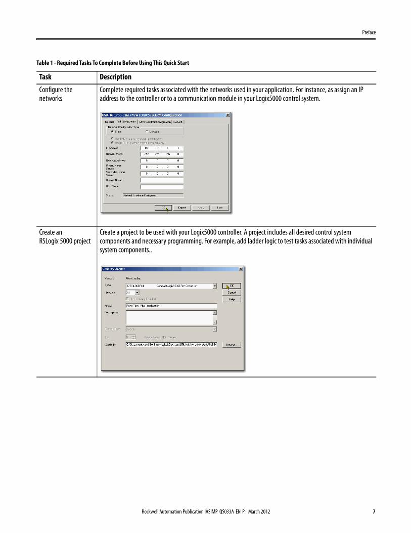
Configure the networks
Complete required tasks associated with the networks used in your application. For instance, as assign an IP address to the controller or to a communication module in your Logix5000 control system.
Create an RSLogix 5000 project
Create a project to be used with your Logix5000 controller. A project includes all desired control system components and necessary programming. For example, add ladder logic to test tasks associated with individual system components..
Table 1 - Required Tasks To Complete Before Using This Quick Start
Task Description
Rockwell Automation Publication IASIMP-QS033A-EN-P - March 2012 7
Preface
Other Logix5000 Control System Quick Starts
This quick start describes how to use one device on one network in a Logix5000 control system. Typically, though, a Logix5000 control system includes more than the controller and one device on one network.
For example, if a Logix5000 control system operates on an EtherNet/IP network, in addition to a controller, power supply, and communication modules, the system might use remote I/O modules, drives and HMI terminals.
Other quick starts describe how to use different devices on different networks in Logix5000 control systems. For more information, see the Integrated Architecture: Logix5000 Control Systems Quick Starts Quick Reference, publication IASIMP-QR024.
Use Each Chapter
The beginning of each chapter contains the following information. You should read these sections before beginning work in each chapter:
• Before You Begin - This section lists the tasks you must complete before starting the chapter.
• What You Need - This section lists the tools that are required to complete the tasks in the chapter.
• Follow These Steps - This section illustrates the steps in the current chapter.
8 Rockwell Automation Publication IASIMP-QS033A-EN-P - March 2012

Preface
Where to Start
Prepare the PanelView Plus Terminal Hardware
page 13
Create a PanelView Plus Application
page 21
Prerequisite TasksDescribed in Before Using This Publication on page 5.
1. Prepare the Logix5000 control system hardware.2. Prepare the computer.3. Configure the networks.4. Create an RSLogix 5000 project.
Logix5000 Controller
Rockwell Automation Publication IASIMP-QS033A-EN-P - March 2012 9

Preface
How Hardware Is Connected
This quick start demonstrates the following possible control system.
Required Software
To complete examples in this quick start, you need the software described in this table.
Software Version Required for This Task
RSLogix 5000 20.00.00 or later(1)
(1) RSLogix 5000 software, version 20.00.00 or later is required for use of this quick start because the example Logix5000 controller, and associated tasks, described herein are
completed in a CompactLogix L3ER control system. CompactLogix L3ER control systems require RSLogix 5000 software, version 20.00.00 or later. If you connect a PanelView Plus terminal over an EtherNet/IP network in a Logix5000 control system that uses a different controller, the minimum version may differ.
Create or change RSLogix 5000 projects to use PanelView Plus terminals
FactoryTalk View Machine Edition(2)
(2) When you install the FactoryTalk View Machine Edition software, you automatically install FactoryTalk Services Platform software and RSLinx Enterprise software.
5.01.00 or later(3)
(3) You can use version 5.01.00 with some Logix5000 controllers. However, the tasks described in this quick start use a 1769-L36ERM controller. That controller requires you to use version 6.00.00 or later and version 6.00.00 is shown in this publication.
Configure the PanelView Plus terminal and execute runtime tasks
RSLinx Enterprise(4)
(4) This software is automatically installed when you install FactoryTalk View Machine Edition software.
5.00.00 or later Complete the tasks described in Chapter 2, Create a PanelView Plus Application on page 21.
12
34
56
78
PanelView Plus Terminal with Built-in EtherNet/IP Port
ComputerLogix5000 Controller with Ethernet
Connection
Stratix 6000 Managed Switch
10 Rockwell Automation Publication IASIMP-QS033A-EN-P - March 2012
Preface
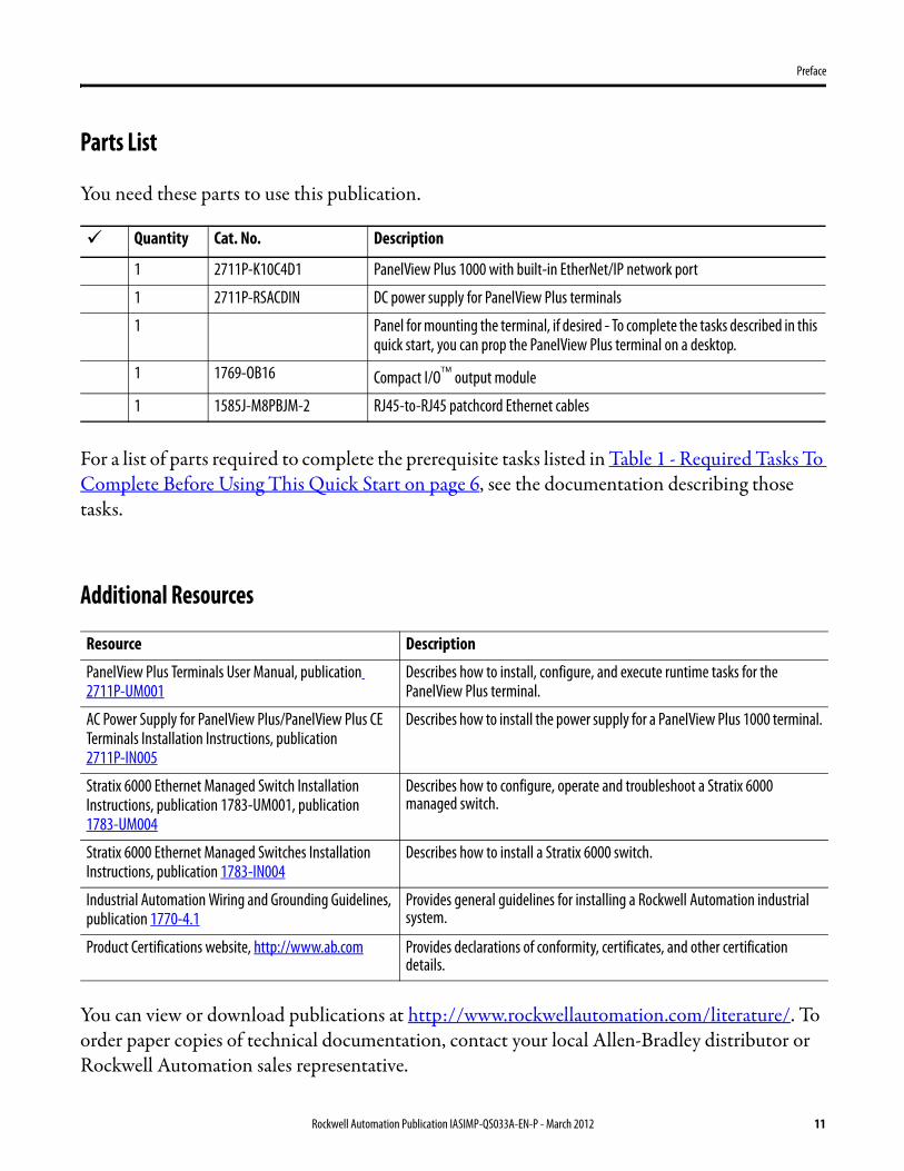
Parts List
You need these parts to use this publication.
For a list of parts required to complete the prerequisite tasks listed in Table 1 - Required Tasks To Complete Before Using This Quick Start on page 6, see the documentation describing those tasks.
Additional Resources
You can view or download publications at http://www.rockwellautomation.com/literature/. To order paper copies of technical documentation, contact your local Allen-Bradley distributor or Rockwell Automation sales representative.
Quantity Cat. No. Description
1 2711P-K10C4D1 PanelView Plus 1000 with built-in EtherNet/IP network port
1 2711P-RSACDIN DC power supply for PanelView Plus terminals
1 Panel for mounting the terminal, if desired - To complete the tasks described in this quick start, you can prop the PanelView Plus terminal on a desktop.
1 1769-OB16 Compact I/O output module
1 1585J-M8PBJM-2 RJ45-to-RJ45 patchcord Ethernet cables
Resource Description
PanelView Plus Terminals User Manual, publication 2711P-UM001
Describes how to install, configure, and execute runtime tasks for the PanelView Plus terminal.
AC Power Supply for PanelView Plus/PanelView Plus CE Terminals Installation Instructions, publication 2711P-IN005
Describes how to install the power supply for a PanelView Plus 1000 terminal.
Stratix 6000 Ethernet Managed Switch Installation Instructions, publication 1783-UM001, publication 1783-UM004
Describes how to configure, operate and troubleshoot a Stratix 6000 managed switch.
Stratix 6000 Ethernet Managed Switches Installation Instructions, publication 1783-IN004
Describes how to install a Stratix 6000 switch.
Industrial Automation Wiring and Grounding Guidelines, publication 1770-4.1
Provides general guidelines for installing a Rockwell Automation industrial system.
Product Certifications website, http://www.ab.com Provides declarations of conformity, certificates, and other certification details.
Rockwell Automation Publication IASIMP-QS033A-EN-P - March 2012 11

Preface
Notes:
12 Rockwell Automation Publication IASIMP-QS033A-EN-P - March 2012

Chapter 1
Prepare the PanelView Plus Terminal Hardware
In this chapter, you learn how to complete the following tasks:• Mount and wire power to a 2711P-K10C4D1 terminal.• Configure EtherNet/IP communication for the terminal.
Before You Begin
You must complete these tasks described in Before Using This Publication on page 5 before using this chapter:
• Prepare the Logix5000 control system hardware• Prepare the computer• Configure the networks - The tasks described in this chapter require an
EtherNet/IP network.• Create an RSLogix 5000 project
The example RSLogix 5000 project used in this chapter uses a CompactLogix 5370 L3 controller.
What You Need
This table lists the products you need to complete the tasks described in this chapter.
Quantity Cat. No. Description
1 2711P-K10C4D1 PanelView Plus terminal with built-in EtherNet/IP network port
1 2711P-RSACDIN DC power supply for PanelView Plus terminals
1 Panel for mounting the terminal - Optional when using this publication
1 1585J-M8PBJM-2 RJ45-to-RJ45 patchcord Ethernet cables
Rockwell Automation Publication IASIMP-QS033A-EN-P - March 2012 13

Chapter 1 Prepare the PanelView Plus Terminal Hardware
Follow These Steps
Mount the PanelView Plus Terminal
In normal applications, you mount a PanelView Plus terminal to a panel. For the purpose of this quick start, however, the PanelView Plus can be propped on a desktop to complete the tasks described herein.
For complete mounting instructions, see the PanelView Plus Terminals User Manual, publication2711P-UM001.
12
34
56
78
Mount the PanelView Plus Terminal
page 14
Connect the Power Supply
page 15
Connect the PanelView Plus Terminal to the EtherNet/IP Network
page 16
Assign an IP Address to the PanelView Plus
Terminalpage 16
GND
+–
GND
14 Rockwell Automation Publication IASIMP-QS033A-EN-P - March 2012

Prepare the PanelView Plus Terminal Hardware Chapter 1
Connect the Power Supply
This quick start uses a PanelView Plus 1000 terminal with built-in Ethernet port and a PanelView Plus Logic module, catalog number 2711P-RP1, Series G. The 2711P-RP1 Logic module uses a 2-position terminal block for power connections.
Complete these steps to connect power to the PanelView Plus terminal.
1. Install the 2711P-RSACDIN DC power supply for the PanelView Plus terminal on a DIN rail.
Do not turn on power to the power supply.
For detailed information on how to install a 2711P-RSACDIN DC power supply, see the AC Power Supply for PanelView Plus/PanelView Plus CE Terminals Installation Instructions, publication 2711P-IN005.
WARNING: Verify that all incoming power is turned off before wiring power.
GND
+–
GND
Earth/Ground to Ground Bus
DC - DC +
2-position Terminal Block
������������
24 VDCPOWER SUPPLY2711P-RSACDIN
POWER
Rockwell Automation Publication IASIMP-QS033A-EN-P - March 2012 15

Chapter 1 Prepare the PanelView Plus Terminal Hardware
2. Gently pull the terminal block off of the PanelView Plus terminal.
3. Connect the 12/24V DC common and 12/24V DC power wires from the power supply to the terminal block, - (common) and + (power).
4. Connect the terminal block to the PanelView Plus terminal.
Connect the PanelView Plus Terminal to the EtherNet/IP Network
1. Connect one end of the 1585J-M8PBJM-2 RJ45-to-RJ45 patchcord Ethernet cable to the EtherNet/IP port on the PanelView Plus terminal.
2. Connect the other end of the cable to an Ethernet switch.
IMPORTANT If you completed the tasks described in the Logix5000 controller quick start for the controller you are using with this quick start, you should already have an Ethernet switch installed on the EtherNet/IP network. If not, install a switch, for example, a Stratix 6000 managed switch, on the EtherNet/IP network before proceeding.
+–
24V DCPOWER SUPPLY2711P-RSACDIN
24V
COM
POWER
PanelView Plus
Common
Power
Front Display on Terminal
EtherNet/IP Port
12
34
56
78
16 Rockwell Automation Publication IASIMP-QS033A-EN-P - March 2012
Prepare the PanelView Plus Terminal Hardware Chapter 1
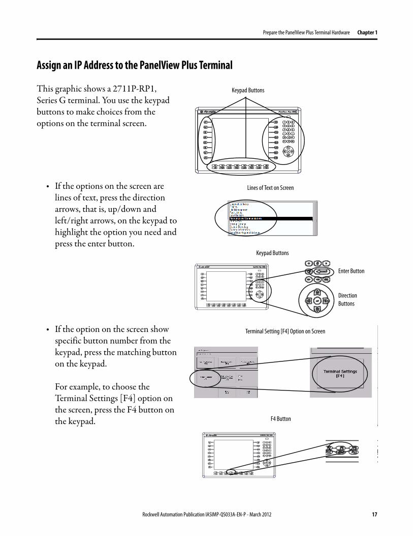
Assign an IP Address to the PanelView Plus Terminal
This graphic shows a 2711P-RP1, Series G terminal. You use the keypad buttons to make choices from the options on the terminal screen.
• If the options on the screen are lines of text, press the direction arrows, that is, up/down and left/right arrows, on the keypad to highlight the option you need and press the enter button.
• If the option on the screen show specific button number from the keypad, press the matching button on the keypad.
For example, to choose the Terminal Settings [F4] option on the screen, press the F4 button on the keypad.
Keypad Buttons
Direction Buttons
Lines of Text on Screen
Enter Button
Keypad Buttons
F4 Button
Terminal Setting [F4] Option on Screen
Rockwell Automation Publication IASIMP-QS033A-EN-P - March 2012 17

Chapter 1 Prepare the PanelView Plus Terminal Hardware
Complete the following steps to assign an IP address to the PanelView Plus terminal.
1. Apply power to the PanelView Plus terminal.
2. When the initial PanelView Plus terminal configuration screen appears on the terminal, press [F4] on the keypad to access the terminal settings.
3. Press the direction arrows and Enter button on the keypad to navigate this path and access the IP address: Networks and Communications>Network Connections>Network Adaptors>Built-in Ethernet Controller>IP Address [F2].
4. Press IP address [F1].
5. Use the numbers on the keypad to assign an IP address to the PanelView Plus terminal.
6. Press the Enter button on the keypad twice.
7. Press Subnet Mask [F2].
8. Use the numbers on the keypad to assign a subnet mask to the PanelView Plus terminal.
9. Press Enter.
18 Rockwell Automation Publication IASIMP-QS033A-EN-P - March 2012
Prepare the PanelView Plus Terminal Hardware Chapter 1
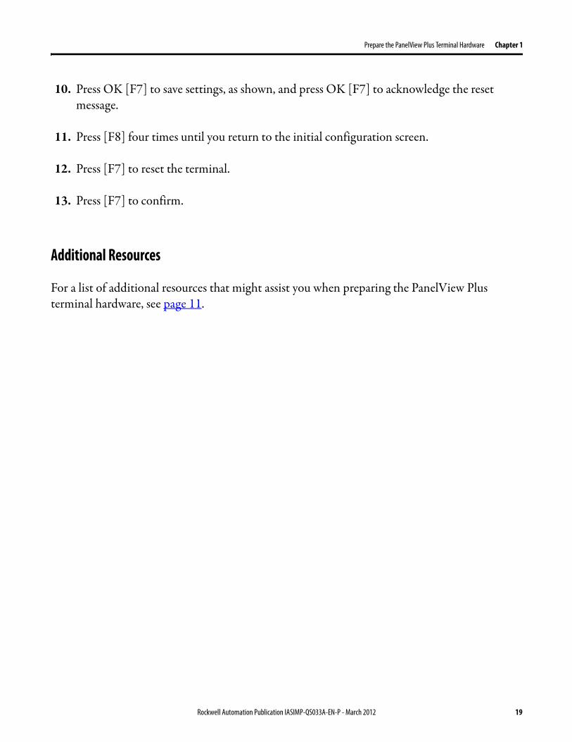
10. Press OK [F7] to save settings, as shown, and press OK [F7] to acknowledge the reset message.
11. Press [F8] four times until you return to the initial configuration screen.
12. Press [F7] to reset the terminal.
13. Press [F7] to confirm.
Additional Resources
For a list of additional resources that might assist you when preparing the PanelView Plus terminal hardware, see page 11.
Rockwell Automation Publication IASIMP-QS033A-EN-P - March 2012 19

Chapter 1 Prepare the PanelView Plus Terminal Hardware
Notes:
20 Rockwell Automation Publication IASIMP-QS033A-EN-P - March 2012

Chapter 2
Create a PanelView Plus Application
In this chapter, you learn how to complete the following tasks:
• Create a push button and a multi-state indicator in FactoryTalk View Studio software.
• Transfer the application to the 2711P-K10C4D1 drive so you can test communication with the controller.
Before You Begin
You must complete these tasks before using this chapter:• The tasks described in Before Using This Publication on page 5, including:
– Prepare the Logix5000 control system hardware– Prepare the computer– Configure the networks - The tasks described in this chapter require an
EtherNet/IP network.– Create an RSLogix 5000 project- In your RSLogix 5000 project, include a ladder logic
rung with Examine On and Output Energize elements as shown. In this example, the alias tag named OB16_Light is an alias for point Local:1:O.Data.0.
The example RSLogix 5000 project used in this chapter uses a CompactLogix 5370 L3 controller.
Rockwell Automation Publication IASIMP-QS033A-EN-P - March 2012 21

Chapter 2 Create a PanelView Plus Application
• Install an I/O module with the following conditions:– Accessible to the PanelView Plus terminal over the EtherNet/IP network– Included in the RSLogix 5000 project used with this quick start.
This publication uses a 1769-OB16 digital output module.
• Prepare the PanelView Plus terminal as described in Chapter 1, Prepare the PanelView Plus Terminal Hardware on page 13, including:– Mount the PanelView Plus Terminal– Connect the Power Supply– Connect the PanelView Plus Terminal to the EtherNet/IP Network– Assign an IP Address to the PanelView Plus Terminal
What You Need
You need the following software to complete the tasks described in this chapter:
• FactoryTalk View Studio software
• RSLinx Enterprise software
• RSLogix 5000 software
IMPORTANT This section describes how to install FactoryTalk View Studio software and RSLinx Enterprise software.
22 Rockwell Automation Publication IASIMP-QS033A-EN-P - March 2012
Create a PanelView Plus Application Chapter 2
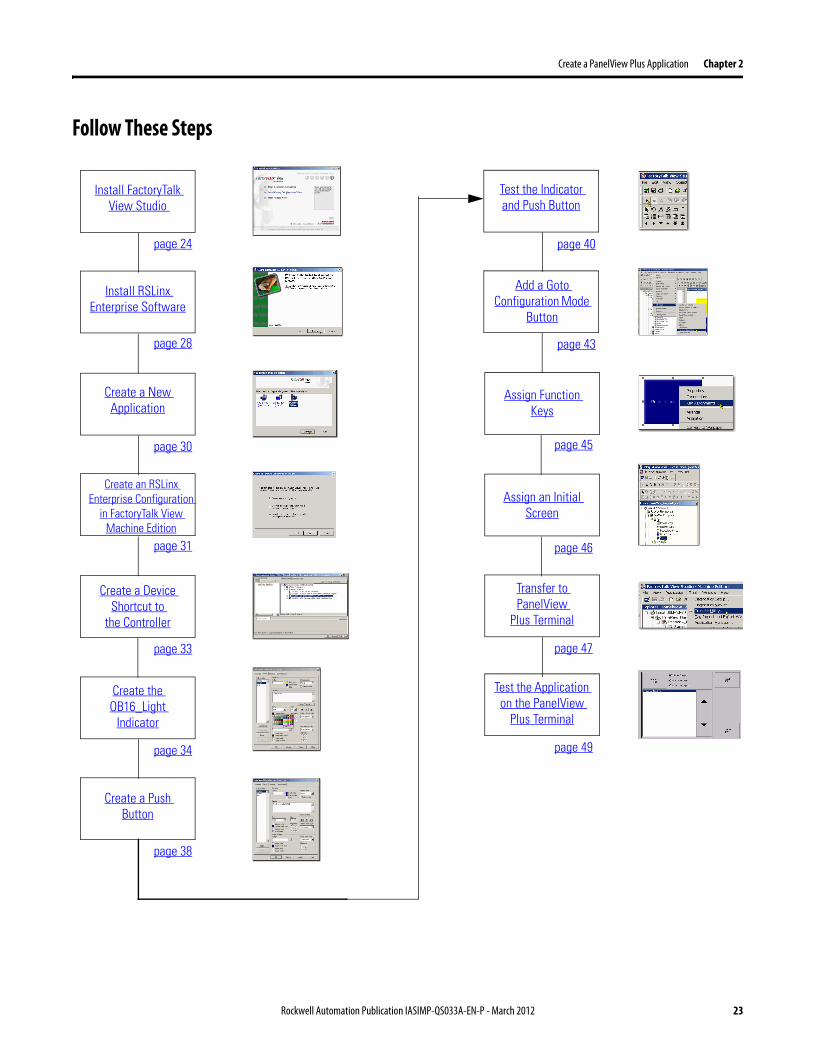
Follow These Steps
Create a New Application
Create an RSLinx Enterprise Configuration
in FactoryTalk View Machine Edition
Create a Device Shortcut to
the Controller
Create the OB16_Light
Indicator
Create a Push Button
Test the Indicator and Push Button
page 30
page 31
page 33
page 34
page 38
page 40
Add a Goto Configuration Mode
Button
page 43
Assign Function Keys
page 45
Assign an Initial Screen
page 46
Transfer to PanelView
Plus Terminal
page 47
Test the Application on the PanelView
Plus Terminal
page 49
Install FactoryTalk View Studio
Install RSLinx Enterprise Software
page 24
page 28
Rockwell Automation Publication IASIMP-QS033A-EN-P - March 2012 23

Chapter 2 Create a PanelView Plus Application
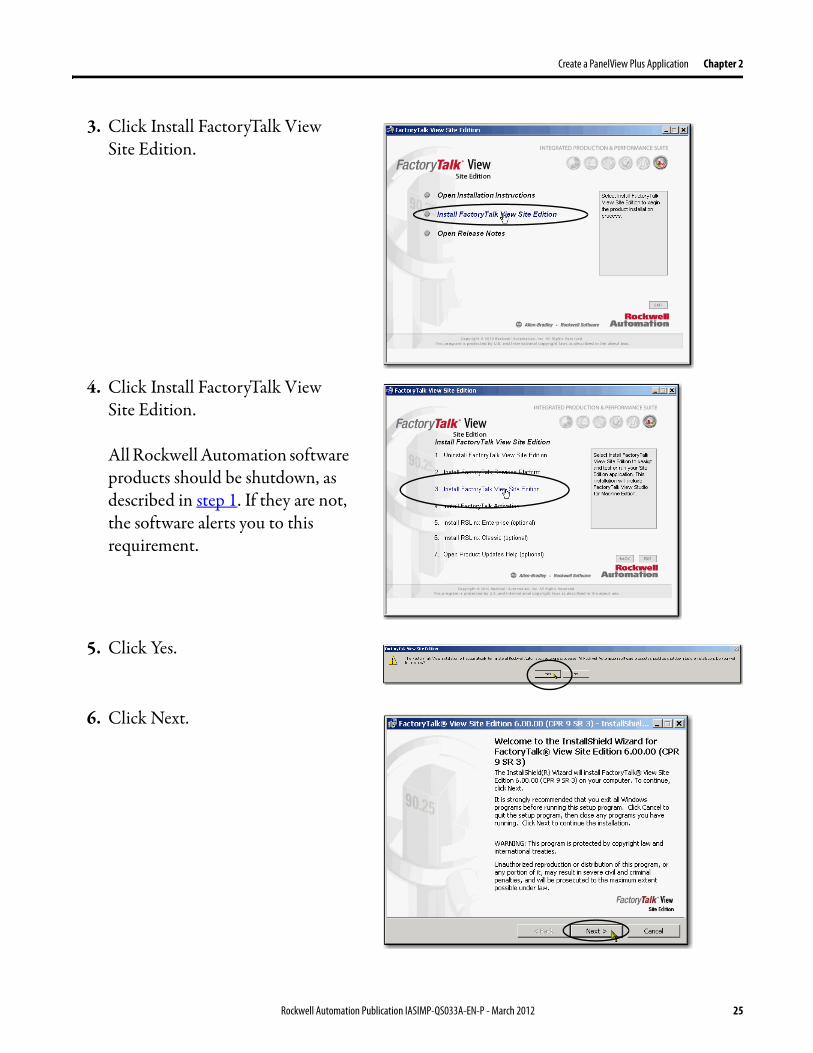
Install FactoryTalk View Studio Software
Throughout the installation, click Next to use default software installation settings, except where indicated.
This section describes how to install the software from a DVD. The following steps describe clicking on FactoryTalk View Site Edition. This set of steps installs both the FactoryTalk View Site Edition and Machine Edition. You can choose Machine Edition when you launch the software after installation.
1. Verify that all Rockwell Automation software processes are shutdown.
2. When the launch screen appears, use this path to begin the installation process: FactoryTalk View>6.00.00>exe.
IMPORTANT The tasks described in this quick start use a 1769-L36ERM controller. That controller requires that you use FactoryTalk View Studio software, version 6.00.00. Therefore, this chapter describes how to use FactoryTalk View Studio software, version 6.00.00.
You can use FactoryTalk View Studio software, version 5.01.00 or earlier (known as FactoryTalk View Studio software) with some Logix5000 controllers. If you choose to use FactoryTalk View Studio software, version 5.01.00 or earlier, be aware that some of the tasks described in this chapter may be completed differently in version 5.01.00 or earlier.
Your computer have FactoryTalk Services Platform software installed on it before you can use the FactoryTalk View Studio software. This quick start assumes you have FactoryTalk Services Platform installed on your computer, do so now before proceeding with the rest of the tasks described in this chapter.
You can install from the same DVD file or downloaded file for FactoryTalk View Studio software.
TIP As installation progresses and depending on your system configuration, you may be prompted to complete additional set-up tasks not described in this chapter.
Follow those prompts and enter information as applies to your installation.
6
24 Rockwell Automation Publication IASIMP-QS033A-EN-P - March 2012
Create a PanelView Plus Application Chapter 2
3. Click Install FactoryTalk View Site Edition.
4. Click Install FactoryTalk View Site Edition.
All Rockwell Automation software products should be shutdown, as described in step 1. If they are not, the software alerts you to this requirement.
5. Click Yes.
6. Click Next.
Rockwell Automation Publication IASIMP-QS033A-EN-P - March 2012 25
Chapter 2 Create a PanelView Plus Application
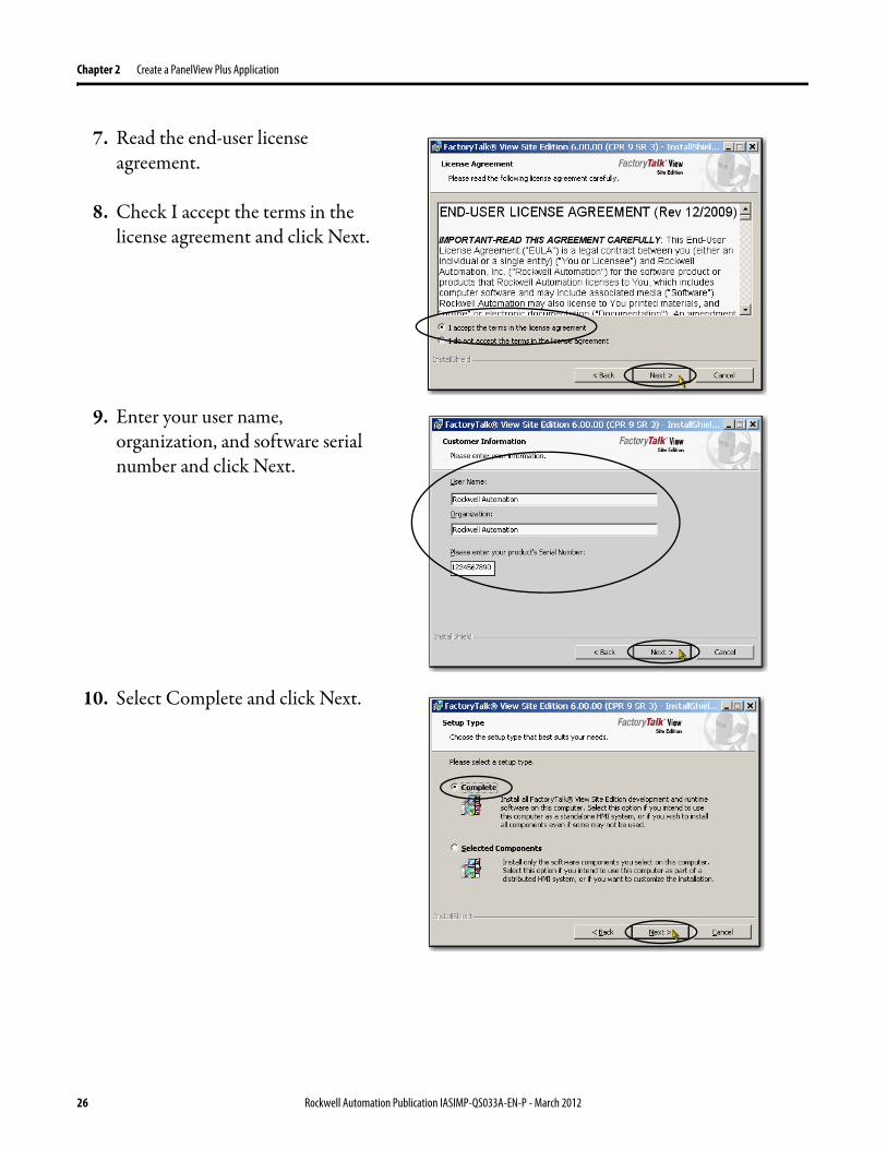
7. Read the end-user license agreement.
8. Check I accept the terms in the license agreement and click Next.
9. Enter your user name, organization, and software serial number and click Next.
10. Select Complete and click Next.
26 Rockwell Automation Publication IASIMP-QS033A-EN-P - March 2012
Create a PanelView Plus Application Chapter 2
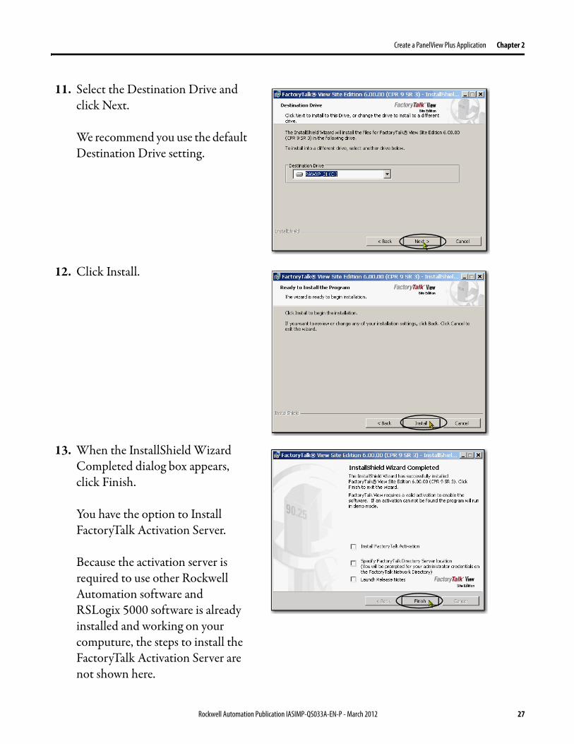
11. Select the Destination Drive and click Next.
We recommend you use the default Destination Drive setting.
12. Click Install.
13. When the InstallShield Wizard Completed dialog box appears, click Finish.
You have the option to Install FactoryTalk Activation Server.
Because the activation server is required to use other Rockwell Automation software and RSLogix 5000 software is already installed and working on your computure, the steps to install the FactoryTalk Activation Server are not shown here.
Rockwell Automation Publication IASIMP-QS033A-EN-P - March 2012 27

Chapter 2 Create a PanelView Plus Application
Install RSLinx Enterprise Software
Throughout the installation, click Next to use default RSLinx Enterprise software installation settings, except when indicated in the following steps.
1. Click Next.
2. Read the license agreement carefully.
3. Check I accept the terms in the license agreement and click Next.
IMPORTANT Your computer must have RSLinx Enterprise software to use FactoryTalk View Studio software. Immediately following the end of installing FactoryTalk View Studio software, the installation process for RSLinx Enterprise software begins automatically.
TIP As installation progresses and depending on your system configuration, you may be prompted to complete additional set-up tasks not described in this chapter.
Follow those prompts and enter information as applies to your installation.
28 Rockwell Automation Publication IASIMP-QS033A-EN-P - March 2012

Create a PanelView Plus Application Chapter 2
4. Enter your user name, organization, and software serial number and click Next.
5. Choose the software setup type and click Next.
We recommend you use Standard Feature Set Installation, as shown.
6. Click Install.
Rockwell Automation Publication IASIMP-QS033A-EN-P - March 2012 29
Chapter 2 Create a PanelView Plus Application
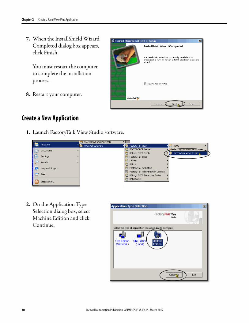
7. When the InstallShield Wizard Completed dialog box appears, click Finish.
You must restart the computer to complete the installation process.
8. Restart your computer.
Create a New Application
1. Launch FactoryTalk View Studio software.
2. On the Application Type Selection dialog box, select Machine Edition and click Continue.
30 Rockwell Automation Publication IASIMP-QS033A-EN-P - March 2012

Create a PanelView Plus Application Chapter 2
3. Select the New tab.
4. Name the application (do not use spaces) and click Create.
Create an RSLinx Enterprise Configuration in FactoryTalk View Machine Edition
1. In the FactoryTalk View organizer, expand RSLinx Enterprise and double-click Communication Setup.
2. Click Finish.
RSLinx Enterprise software opens.
Rockwell Automation Publication IASIMP-QS033A-EN-P - March 2012 31
Chapter 2 Create a PanelView Plus Application
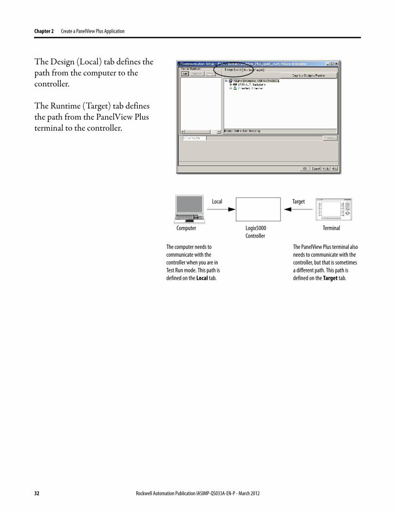
The Design (Local) tab defines the path from the computer to the controller.
The Runtime (Target) tab defines the path from the PanelView Plus terminal to the controller.
Computer Logix5000 Controller
Terminal
TargetLocal
The computer needs to communicate with the controller when you are in Test Run mode. This path is defined on the Local tab.
The PanelView Plus terminal also needs to communicate with the controller, but that is sometimes a different path. This path is defined on the Target tab.
32 Rockwell Automation Publication IASIMP-QS033A-EN-P - March 2012
Create a PanelView Plus Application Chapter 2
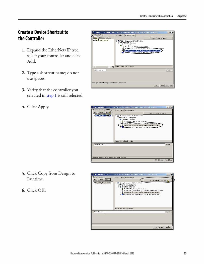
Create a Device Shortcut to the Controller
1. Expand the EtherNet/IP tree, select your controller and click Add.
2. Type a shortcut name; do not use spaces.
3. Verify that the controller you selected in step 1 is still selected.
4. Click Apply.
5. Click Copy from Design to Runtime.
6. Click OK.
Rockwell Automation Publication IASIMP-QS033A-EN-P - March 2012 33

Chapter 2 Create a PanelView Plus Application
Create the OB16_Light Indicator
1. Verify that you have created an RSLogix 5000 project that includes an output module and a ladder logic rung with Examine On and Output Energize elements similar to the one shown.
This example, the alias tag named OB16_Light is an alias for point Local:1:O:Data.0. You might choose to use a different point on the module. If so, verify that the alias tag is set to the correct module point.
2. Go online with your controller and download the RSLogix 5000 project.
3. Open the Explorer section of FactoryTalk View Machine Edition software as shown in the following graphic.
4. Under Graphics, right-click Displays and choose New.
5. Choose Objects>Indicator Multistate.
34 Rockwell Automation Publication IASIMP-QS033A-EN-P - March 2012

Create a PanelView Plus Application Chapter 2
6. Click and drag to create the indicator.
7. Right-click and choose Properties.
8. On the General tab, select 2 for the Number of states.
9. On the States tab, verify that State0 is selected.
10. In the Caption, type Light is OFF.
Rockwell Automation Publication IASIMP-QS033A-EN-P - March 2012 35
Chapter 2 Create a PanelView Plus Application
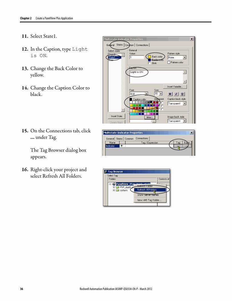
11. Select State1.
12. In the Caption, type Light is ON.
13. Change the Back Color to yellow.
14. Change the Caption Color to black.
15. On the Connections tab, click ... under Tag.
The Tag Browser dialog box appears.
16. Right-click your project and select Refresh All Folders.
36 Rockwell Automation Publication IASIMP-QS033A-EN-P - March 2012
Create a PanelView Plus Application Chapter 2
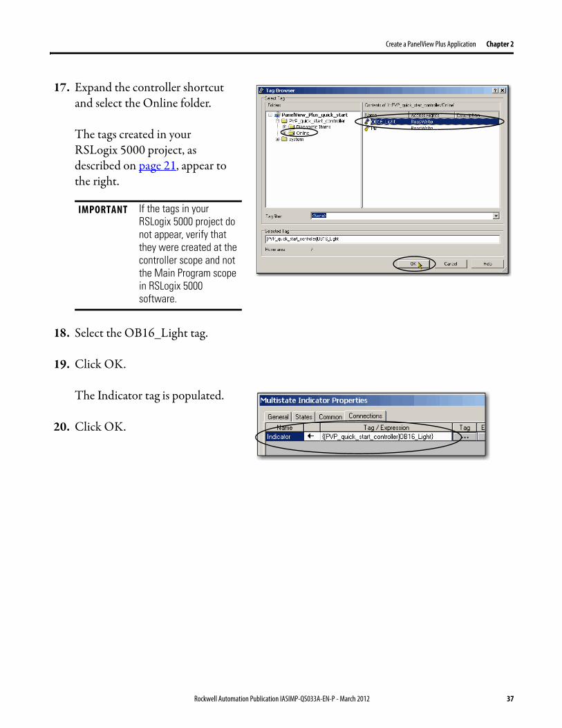
17. Expand the controller shortcut and select the Online folder.
The tags created in your RSLogix 5000 project, as described on page 21, appear to the right.
18. Select the OB16_Light tag.
19. Click OK.
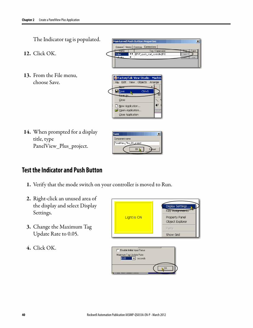
The Indicator tag is populated.
20. Click OK.
IMPORTANT If the tags in your RSLogix 5000 project do not appear, verify that they were created at the controller scope and not the Main Program scope in RSLogix 5000 software.
Rockwell Automation Publication IASIMP-QS033A-EN-P - March 2012 37
Chapter 2 Create a PanelView Plus Application
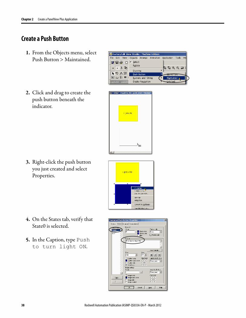
Create a Push Button
1. From the Objects menu, select Push Button Maintained.
2. Click and drag to create the push button beneath the indicator.
3. Right-click the push button you just created and select Properties.
4. On the States tab, verify that State0 is selected.
5. In the Caption, type Push to turn light ON.
38 Rockwell Automation Publication IASIMP-QS033A-EN-P - March 2012
Create a PanelView Plus Application Chapter 2
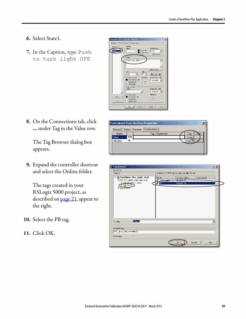
6. Select State1.
7. In the Caption, type Push to turn light OFF.
8. On the Connections tab, click ... under Tag in the Value row.
The Tag Browser dialog box appears.
9. Expand the controller shortcut and select the Online folder.
The tags created in your RSLogix 5000 project, as described on page 21, appear to the right.
10. Select the PB tag.
11. Click OK.
Rockwell Automation Publication IASIMP-QS033A-EN-P - March 2012 39
Chapter 2 Create a PanelView Plus Application
The Indicator tag is populated.
12. Click OK.
13. From the File menu, choose Save.
14. When prompted for a display title, type PanelView_Plus_project.
Test the Indicator and Push Button
1. Verify that the mode switch on your controller is moved to Run.
2. Right-click an unused area of the display and select Display Settings.
3. Change the Maximum Tag Update Rate to 0.05.
4. Click OK.
40 Rockwell Automation Publication IASIMP-QS033A-EN-P - March 2012
Create a PanelView Plus Application Chapter 2
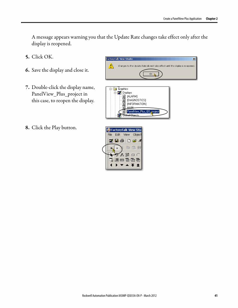
A message appears warning you that the Update Rate changes take effect only after the display is reopened.
5. Click OK.
6. Save the display and close it.
7. Double-click the display name, PanelView_Plus_project in this case, to reopen the display.
8. Click the Play button.
Rockwell Automation Publication IASIMP-QS033A-EN-P - March 2012 41
Chapter 2 Create a PanelView Plus Application
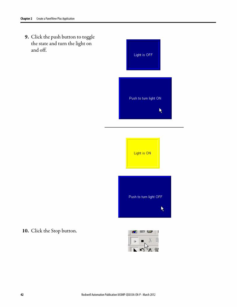
9. Click the push button to toggle the state and turn the light on and off.
10. Click the Stop button.
42 Rockwell Automation Publication IASIMP-QS033A-EN-P - March 2012
Create a PanelView Plus Application Chapter 2
Add a Goto Configuration Mode Button
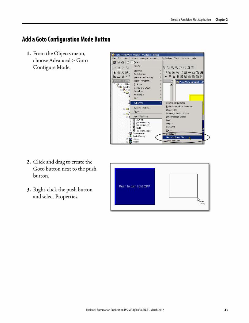
1. From the Objects menu, choose Advanced Goto Configure Mode.
2. Click and drag to create the Goto button next to the push button.
3. Right-click the push button and select Properties.
Rockwell Automation Publication IASIMP-QS033A-EN-P - March 2012 43
Chapter 2 Create a PanelView Plus Application
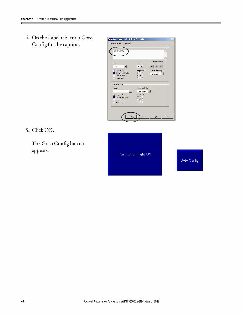
4. On the Label tab, enter Goto Config for the caption.
5. Click OK.
The Goto Config button appears.
44 Rockwell Automation Publication IASIMP-QS033A-EN-P - March 2012
Create a PanelView Plus Application Chapter 2
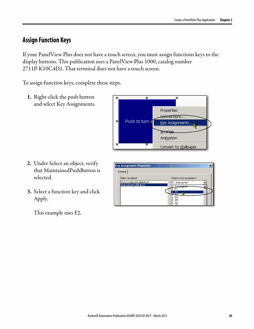
Assign Function Keys
If your PanelView Plus does not have a touch screen, you must assign functions keys to the display buttons. This publication uses a PanelView Plus 1000, catalog number 2711P-K10C4D1. That terminal does not have a touch screen.
To assign function keys, complete these steps.
1. Right-click the push button and select Key Assignments.
2. Under Select an object, verify that MaintainedPushButton is selected.
3. Select a function key and click Apply.
This example uses F2.
Rockwell Automation Publication IASIMP-QS033A-EN-P - March 2012 45
Chapter 2 Create a PanelView Plus Application
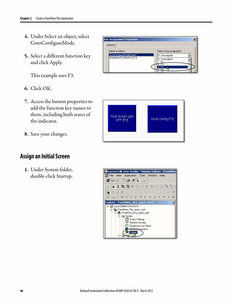
4. Under Select an object, select GotoConfigureMode.
5. Select a different function key and click Apply.
This example uses F3.
6. Click OK.
7. Access the button properties to add the function key names to them, including both states of the indicator.
8. Save your changes.
Assign an Initial Screen
1. Under System folder, double-click Startup.
46 Rockwell Automation Publication IASIMP-QS033A-EN-P - March 2012

Create a PanelView Plus Application Chapter 2
2. Check Initial graphic and select PanelView_Plus_project, or the initial display name if different, from the pull-down menu.
3. Click OK.
4. Save your changes.
Transfer to PanelView Plus Terminal
1. From the Application menu, choose Create Runtime Application.
2. In Save as type, select the Runtime version that matches your PanelView Plus firmware.
To check the PanelView Plus firmware revision, on the terminal select Terminal Setting [F4] System Information About FactoryTalk View ME Station
3. Click Save to accept the default file name.
Rockwell Automation Publication IASIMP-QS033A-EN-P - March 2012 47

Chapter 2 Create a PanelView Plus Application
4. From the Tools menu, choose Transfer Utility.
5. Click the ... button.
6. Select the .mer file you just created and click Open.
7. Verify the following:
• Run application when download completes is checked
• Replace communications is checked
• Your PanelView Plus is selected for the destination terminal
8. Click Download.
The download process may take a few minutes.
48 Rockwell Automation Publication IASIMP-QS033A-EN-P - March 2012
Create a PanelView Plus Application Chapter 2
9. When the Transfer Utility dialog box appears, click OK.
10. Exit the Transfer Utility.
Test the Application on the PanelView Plus Terminal
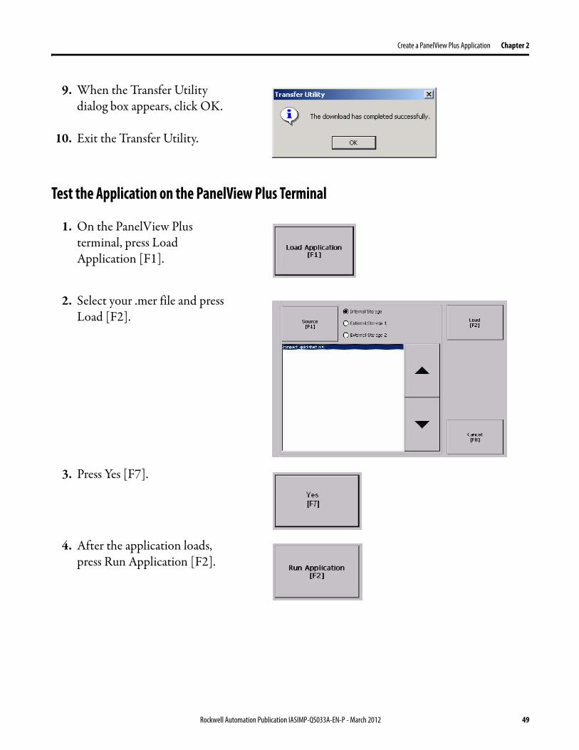
1. On the PanelView Plus terminal, press Load Application [F1].
2. Select your .mer file and press Load [F2].
3. Press Yes [F7].
4. After the application loads, press Run Application [F2].
Rockwell Automation Publication IASIMP-QS033A-EN-P - March 2012 49
Chapter 2 Create a PanelView Plus Application
5. Press the push button and verify that the indicator turns on and that the light on the Compact digital output module turns on.
6. Press the push button again and verify that the indicator and light turn off.
Additional Resources
For a list of additional resources that might assist you when creating a PanelView Plus application, see page 11.
50 Rockwell Automation Publication IASIMP-QS033A-EN-P - March 2012

Index
Cconnections
hardware 10, 15-16
EEthernet adapter
assign IP address 17-19connect terminal to network 16
FFactoryTalk View Machine Edition
requirements 10FactoryTalk View Studio software
install 24-27
Hhardware
connect Ethernet adapter 16example control system 10mount terminal 14preparation 13-16required parts 11wire power 15-16
IIP address
assign to Ethernet adapter 17-19
LLogix5000 controllers
prerequisite tasks 5-7
Pparts
PanelView Plus terminal 11required to complete tasks 11
powerconnect to terminal 15-16
Qquick starts
for devices in Logix5000 control systems 8
Rrequirements
hardware preparation 13-19parts 11prerequisite tasks 5-7software 10
RSLinx Enterprise softwareinstall 28-31requirements 10
RSLogix 5000 softwarerequirements 6, 10
Ssoftware
FactoryTalk View Machine Edition 10install FactoryTalk View 24-27install RSLinx Enterprise 28-31RSLinx Enterprise 10RSLogix 5000 10
Stratix 6000 swtich 11
Rockwell Automation Publication IASIMP-QS033A-EN-P - March 2012 51

Index
Notes:
52 Rockwell Automation Publication IASIMP-QS033A-EN-P - March 2012


Rockwell Otomasyon Ticaret A.Ş., Kar Plaza İş Merkezi E Blok Kat:6 34752 İçerenköy, İstanbul, Tel: +90 (216) 5698400
Publication IASIMP-QS033A-EN-P - March 2012Copyright © 2012 Rockwell Automation, Inc. All rights reserved. Printed in the U.S.A.
Rockwell Automation Support
Rockwell Automation provides technical information on the Web to assist you in using its products. At http://www.rockwellautomation.com/support/, you can find technical manuals, a knowledge base of FAQs, technical and application notes, sample code and links to software service packs, and a MySupport feature that you can customize to make the best use of these tools.
For an additional level of technical phone support for installation, configuration, and troubleshooting, we offer TechConnect support programs. For more information, contact your local distributor or Rockwell Automation representative, or visit http://www.rockwellautomation.com/support/.
Installation Assistance
If you experience a problem within the first 24 hours of installation, review the information that is contained in this manual. You can contact Customer Support for initial help in getting your product up and running.
New Product Satisfaction Return
Rockwell Automation tests all of its products to ensure that they are fully operational when shipped from the manufacturing facility. However, if your product is not functioning and needs to be returned, follow these procedures.
Documentation Feedback
Your comments will help us serve your documentation needs better. If you have any suggestions on how to improve this document, complete this form, publication RA-DU002, available at http://www.rockwellautomation.com/literature/.
United States or Canada 1.440.646.3434
Outside United States or Canada Use the Worldwide Locator at http://www.rockwellautomation.com/support/americas/phone_en.html, or contact your local Rockwell Automation representative.
United States Contact your distributor. You must provide a Customer Support case number (call the phone number above to obtain one) to your distributor to complete the return process.
Outside United States Please contact your local Rockwell Automation representative for the return procedure.
Power, Control and Information Solutions HeadquartersAmericas: Rockwell Automation, 1201 South Second Street, Milwaukee, WI 53204-2496 USA, Tel: (1) 414.382.2000, Fax: (1) 414.382.4444Europe/Middle East/Africa: Rockwell Automation NV, Pegasus Park, De Kleetlaan 12a, 1831 Diegem, Belgium, Tel: (32) 2 663 0600, Fax: (32) 2 663 0640Asia Pacific: Rockwell Automation, Level 14, Core F, Cyberport 3, 100 Cyberport Road, Hong Kong, Tel: (852) 2887 4788, Fax: (852) 2508 1846
www.rockwel lautomation.com