low frequency multi-mode pipe projectorcradpdf.drdc-rddc.gc.ca/pdfs/unc57/p527289.pdf · low...
TRANSCRIPT

Defence R&D Canada – Atlantic
DEFENCE DÉFENSE&
Low Frequency Multi-Mode Pipe Projector
Richard A.G. Fleming
Technical Memorandum
DRDC Atlantic TM 2006-248
November 2006
Copy No.________
Defence Research andDevelopment Canada
Recherche et développementpour la défense Canada

This page intentionally left blank.
Low Frequency Multi-Mode Pipe Projector
Richard A.G. Fleming
Defence R&D Canada – Atlantic TECHNICAL MEMORANDUM DRDC Atlantic TM 2006-248 December 2006

DRDC Atlantic TM 2006-248 i
Abstract
The multi-mode pipe projector (MMPP) is a recently patented sonar projector capable of very wide bandwidth. The projector generates this bandwidth with an optimized approach to overlapping numerous drive motor and waveguide resonances. The low frequency MMPP (LF MMPP) was developed by scaling the original 3-35 kHz MMPP’s dimensions by 5/2 and optimizing for an available piezoelectric ring size for a projected bandwidth of 1.3-13 kHz. A single prototype was built and tested and its bandwidth mirrored the finite element predictions for performance. Deep water testing revealed distortion-limited shallow-water performance, which will require the LF MMPP to be operated at a depth of more than 266 m at high drive voltage.
Résumé
Le projecteur à tube multimode (MMPP) est un projecteur sonar récemment breveté qui peut fonctionner dans une très grande largeur de bande. Cette largeur de bande est obtenue selon une approche qui optimise le chevauchement de nombreuses résonances de moteurs d’entraînement et de guides d’ondes. Le MMPP basse fréquence (LF) réduit de 5/2 les dimensions du MMPP d'origine entre 3 et 35 kHz et optimise la taille de l’anneau piézoélectrique disponible pour produire une largeur de bande projetée allant de 1,3 à 13 kHz. Un seul prototype a été construit et mis à l'essai, et sa performance s’accorde bien avec les prévisions par éléments finis. Les essais en eau profonde ont révélé une performance en eau peu profonde présentant une distorsion limitée, ce qui exige l'utilisation du MMPP basse fréquence à une profondeur de plus de 266 m pour une tension de commande élevée.

ii DRDC Atlantic TM 2006-248
This page intentionally left blank.
DRDC Atlantic TM 2006-248 iii
Executive summary
Introduction
Wideband sonar projectors are currently under development at DRDC Atlantic to provide multi-role projector solutions and permit transmission of spread-spectrum waveforms. These projectors could have a myriad of applications such as underwater communications, and torpedo counter-measures. The multi-mode projector (MMPP) provides wideband operation by means of numerous overlapping vibrational modes. The development of the first generation MMPP focussed on decreasing the lowest frequency of operation while maintaining broadband characteristics. It was decided to explore the low frequency limits of the wideband aspect ratio given the available piezoceramic motor materials. This scaling effort was first modelled using finite element techniques and a prototype was built and tested.
Results
The LF MMPP was predicted to have a broadside transmitting voltage response (TVR) of no less than 125 dB re 1 μPa/Vrms @ 1m from 1.3 to 13 kHz. The prototype exhibited a broadside TVR of no less than 122 dB re 1 μPa/Vrms @ 1m from 1.3 to 13 kHz. Distortion onset testing revealed that 5% harmonic distortion at the first resonance occurred at from 70 Vrms at 3.4 m depth to 710 Vrms at 50.4 m depth.
Significance
The creation of such a broadband, low frequency transducer makes possible a wide range of applications of a single projector. This projector can reproduce much of the audible band at very high source levels. As well, the broadband characteristic can be exploited to provide the means for broadband transmission of complex waveforms in counter-measure and covert applications.
The scaling of an existing model coupled with a design incorporating standard motor components leads to a very low cost sonar projector both in terms of design effort and prototype expense. This results in a streamlined approach to further development of the MMPP design in terms of customizing projector performance with a specific performance goal in mind.
Future Plans
The next step in the development of the LF MMPP design is to measure the projector’s directivity index over a range of frequencies and use these results to validate the MAVART predicted directivity index. As well, the phase and spectral correction techniques will be employed to optimize the performance of the existing prototype. Life cycle prediction and testing of MMPP’s in general is to be carried out.
Fleming, R.A.G. 2006. Low Frequency Multi-Mode Pipe Projector. DRDC Atlantic TM 2006-248. Defence R&D Canada – Atlantic.
iv DRDC Atlantic TM 2006-248
Sommaire
Introduction
Des projecteurs sonar à large bande sont en cours de développement à RDDC Atlantique afin de fournir des solutions multi-rôles permettant la transmission d'ondes à spectre étalé. Ces projecteurs pourraient trouver une myriade d'applications, par exemple dans les domaines des télécommunications sous-marines et des contre-mesures anti-torpilles. Le projecteur à tube multimode (MMPP) fonctionne en large bande en exploitant le chevauchement de nombreux modes vibratoires. Le développement de la première génération de MMPP visait principalement à diminuer la plus basse fréquence de fonctionnement tout en maintenant les caractéristiques de large bande. On a décidé d’examiner les limites de fréquence inférieure du rapport d'aspect à large bande compte tenu des matériaux moteurs en piézocéramique qui sont disponibles. À cette fin, on a d’abord procédé à une modélisation par éléments finis, puis un prototype a été construit et mis à l’essai.
Résultats
Le MMPP basse fréquence (LF) devait, selon les prévisions, présenter une réponse en tension d’émission (TVR) de travers d’au moins 125 dB, rapportée à 1 μPa/V eff.. à 1 m de 1,3 à 13 kHz. Le prototype présentait une TVR de travers d’au moins 122 dB, rapportée à 1 μPa/V eff. à 1 m de 1,3 à 13 kHz. L'essai d'apparition de distorsion a révélé qu'une distorsion harmonique de 5 % au premier point de résonance se produisait entre 70 V eff. à une profondeur de 3,4 m et 710 V eff. à une profondeur de 50,4 m.
Portée
En fonctionnant dans cette large bande, un tel transducteur basse fréquence peut être utilisé comme projecteur unique dans un large éventail d’applications. Le projecteur peut reproduire une grande partie de la bande des fréquences audibles à des niveaux de source très élevés. En outre, on peut exploiter la caractéristique large bande pour la transmission à large bande d’ondes complexes aux fins d’applications dans les domaines des contre-mesures et de la dissimulation. L’extension de la gamme de fréquences d’un modèle existant, associée à une conception intégrant des éléments de moteur standard, permet d’obtenir un projecteur sonar très bon marché du point de vue des efforts de conception et du financement des prototypes, d’où une approche simplifiée pour les travaux futurs de conception de MMPP visant l’adaptation de la performance des projecteurs à un objectif précis.
Recherches futures
La prochaine étape du développement de la conception du MMPP basse fréquence consiste à mesurer l'indice de directivité du projecteur dans une gamme de fréquences et à utiliser les résultats pour valider l'indice de directivité prévu par MAVART. Par ailleurs, des techniques de correction de phase et de fréquence permettront d'optimiser la performance du prototype existant. Il reste à effectuer la prévision du cycle de vie et l'essai des MMPP en général.
Fleming, R.A.G. 2006. Low Frequency Multi-Mode Pipe Projector (projecteur à tube multimode basse fréquence). DRDC Atlantic TM 2006-248. Defence R&D Canada – Atlantic.
DRDC Atlantic TM 2006-248 v
Table of contents
Abstract........................................................................................................................................ i
Executive summary ................................................................................................................... iii
Sommaire................................................................................................................................... iv
Table of contents ........................................................................................................................ v
List of figures ............................................................................................................................ vi
Acknowledgements .................................................................................................................. vii
1. Introduction ............................................................................................................................ 1
2. Design.................................................................................................................................... 3
3. Prototype Construction ........................................................................................................... 5
4. Testing .................................................................................................................................. 10
5. Conclusion............................................................................................................................ 13
6. References ............................................................................................................................ 14
List of symbols/abbreviations/acronyms/initialisms ................................................................ 15

vi DRDC Atlantic TM 2006-248
List of figures
Figure 1. Mid-frequency multi-mode pipe projector .................................................................. 1
Figure 2. MMPP parts prior to assembly.................................................................................... 1
Figure 3. Mid-frequency MMPP broadside TVR....................................................................... 2
Figure 4. 1st quadrant ModelMaker 2D model of LF MMPP..................................................... 3
Figure 5. MAVART-predicted broadside (blue) and endfire (red) TVR’s for initial optimized LF MMPP............................................................................................................................ 4
Figure 6. Bottom endcap of LF MMPP...................................................................................... 5
Figure 7. Stainless steel prestress rod ......................................................................................... 6
Figure 8. Top endcap of LF MMPP ........................................................................................... 6
Figure 9. Piezoceramic drive motor subassembly ...................................................................... 7
Figure 10. Stainless steel mount ................................................................................................. 8
Figure 11. MMPP family with LF MMPP on extreme right and mid-frequency MMPP on extreme left.......................................................................................................................... 9
Figure 12. LF MMPP broadside MAVART prediction to measurement comparison.............. 10
Figure 13. LF MMPP endfire MAVART prediction to measurement comparison.................. 11
Figure 14. Total harmonic distortion as a function of drive voltage ........................................ 12
Figure 15. Linear fit of 5% THD points at various depths ....................................................... 12
DRDC Atlantic TM 2006-248 vii
Acknowledgements I wish to acknowledge the MMPP’s co-inventor Dr. C.J. Purcell for his assistance in the deep-water distortion testing of the LF MMPP. I wish also to thank Charles Reithmeier for his peerless craftsmanship as demonstrated in the construction of the prototype LF MMPP.

viii DRDC Atlantic TM 2006-248
This page intentionally left blank.

DRDC Atlantic TM 2006-248 1
1. Introduction
The Multi-mode Pipe Projector (MMPP) was invented at DRDC-Atlantic and received a US patent in June 2003 (see Figure 1)[1]. The projector is designed to operate over a very wide frequency range by employing numerous overlapping vibrational modes. Unlike gas-backed flextensional designs [2], the mostly free-flooded MMPP’s performance is insensitive to hydrostatic loading [3].
Figure 1. Mid-frequency multi-mode pipe projector
The MMPP is composed of a central drive motor, opposed free-flooding aluminum waveguides, stainless steel prestress rods, wiring and waterproofing materials (see Fig. 2).
Figure 2. MMPP parts prior to assembly
Initial prototypes of the projector were designed to achieve the lowest possible frequency while maintaining broadband response in a device that would readily fit into an A-size sonobuoy. The
2 DRDC Atlantic TM 2006-248
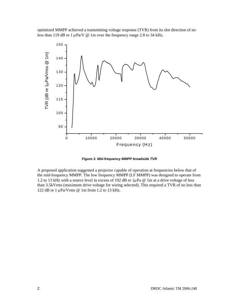
optimized MMPP achieved a transmitting voltage response (TVR) from its slot direction of no less than 119 dB re 1 μPa/V @ 1m over the frequency range 2.8 to 34 kHz.
0 10000 20000 30000 40000 50000
90
100
110
120
130
140
150TV
R (d
B re
1μP
a/Vr
ms
@ 1
m)
F requency (H z)
Figure 3. Mid-frequency MMPP broadside TVR
A proposed application suggested a projector capable of operation at frequencies below that of the mid-frequency MMPP. The low frequency MMPP (LF MMPP) was designed to operate from 1.2 to 13 kHz with a source level in excess of 192 dB re 1μPa @ 1m at a drive voltage of less than 3.5kVrms (maximum drive voltage for wiring selected). This required a TVR of no less than 122 dB re 1 μPa/Vrms @ 1m from 1.2 to 13 kHz.

DRDC Atlantic TM 2006-248 3
2. Design
Design of the LF MMPP centered on scaling the mid-frequency MMPP’s piezoceramic drive motor diameter to the maximum piezoceramic ring size available at DRDC Atlantic. The largest PZT-4 piezoceramic rings available at DRDC Atlantic were 9.27 cm inside diameter (ID), 12.7 cm outside diameter (OD) and 1.41 cm thick. Based on this dimension, simple scaling with respect to the aspect ratio of the drive motor in the mid-frequency MMPP, the LF MMPP would have a drive motor approximately 2.5 times longer than the mid-frequency MMPP or 25.4 cm overall. Scaling up the mid-frequency MMPP’s structural dimensions by 2.5 would inversely scale the bandwidth resulting in a 1.12 to 13.5 kHz band of operation.
Since the proposed LF MMPP would have a mass 2.53 times greater than the mid-frequency MMPP’s 2 kg mass, incorporation of an integral mounting scheme was required (proposed mass 31.25 kg). It was decided that a mounting ring at the central node of the drive motor would be included to allow both vertical and horizontal projector orientations. This mounting ring would replace the two central piezoceramic rings and thus simplify finite element optimization of the design by retaining ring dimensions.
The geometry of the LF MMPP was generated with the ModelMaker add-on for Mathematica™. Since the MMPP is essentially symmetric in both rotational and axial aspects, the first quadrant of the geometry captured all of the physics in the finite element solution. The model (see Fig. 4) is composed of a total of 221 elements of which 20 are aluminum, 8 are piezoceramic, 2 are the stainless steel mount and 181 are water.
Figure 4. 1st quadrant ModelMaker 2D model of LF MMPP.
4 DRDC Atlantic TM 2006-248
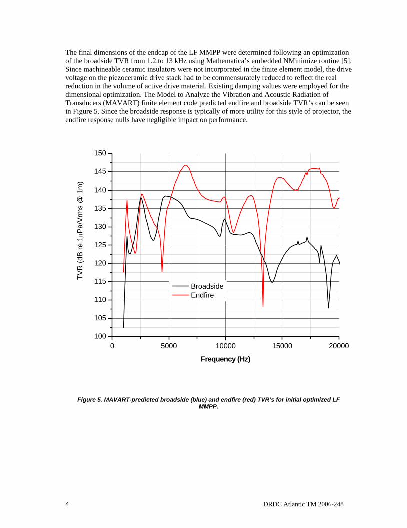
The final dimensions of the endcap of the LF MMPP were determined following an optimization of the broadside TVR from 1.2.to 13 kHz using Mathematica’s embedded NMinimize routine [5]. Since machineable ceramic insulators were not incorporated in the finite element model, the drive voltage on the piezoceramic drive stack had to be commensurately reduced to reflect the real reduction in the volume of active drive material. Existing damping values were employed for the dimensional optimization. The Model to Analyze the Vibration and Acoustic Radiation of Transducers (MAVART) finite element code predicted endfire and broadside TVR’s can be seen in Figure 5. Since the broadside response is typically of more utility for this style of projector, the endfire response nulls have negligible impact on performance.
0 5000 10000 15000 20000100
105
110
115
120
125
130
135
140
145
150
TVR
(dB
re 1μP
a/V
rms
@ 1
m)
Frequency (Hz)
Broadside Endfire
Figure 5. MAVART-predicted broadside (blue) and endfire (red) TVR’s for initial optimized LF MMPP.

DRDC Atlantic TM 2006-248 5
3. Prototype Construction
Prototype construction a LF MMPP’s was carried out at DRDC-Atlantic and consisted of waveguide machining, drive motor assembly and characterization, waveguide-to-drive motor mating, external wiring, and waterproofing.
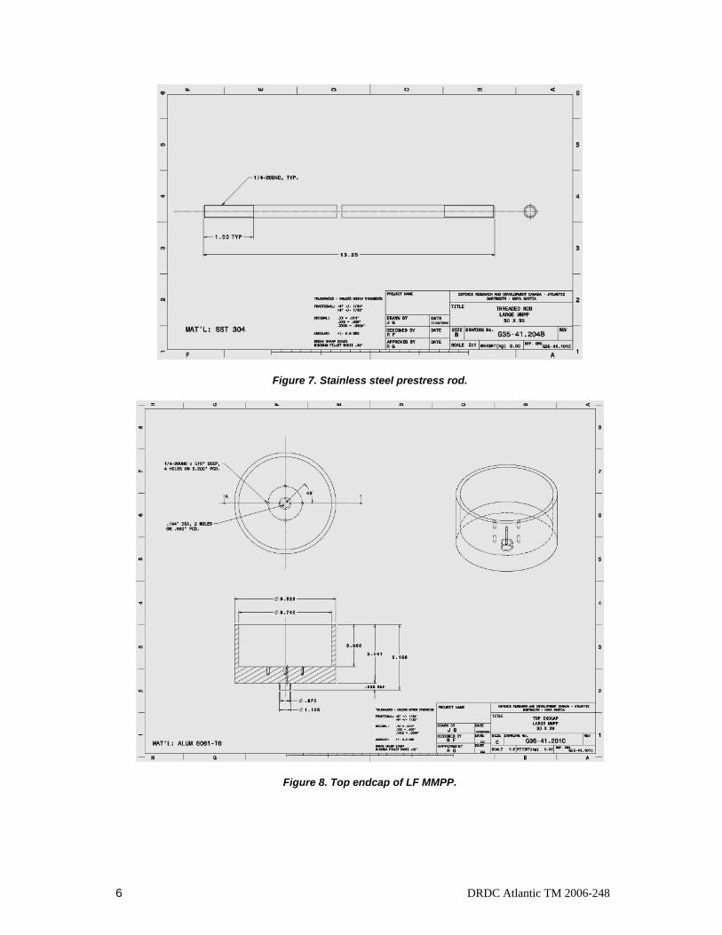
The LF MMPP’s waveguides are machined from 6061T-6 aluminum and are 5.541” long, 9.528” OD, 8.740” ID, 1.575” endcap thickness. The bottom endcap (see Figure 6) has four-0.281” ID through-holes for the ¼” diameter stainless steel prestress rods (see figure 7) while the other has blind-tapped holes for the other end of the prestress rods (see Figure 8). The endcap in Figure 8 also has two 0.144” holes drilled for the exit of the drive motor wires and an integral potting cup for waterproofing of wires.
Not shown in the drawings are 3 holes 1/8” diameter drilled through the wall of the top endcap to permit the escape of air when the LF MMPP is lowered vertically into the water.
Figure 6. Bottom endcap of LF MMPP.
6 DRDC Atlantic TM 2006-248
Figure 7. Stainless steel prestress rod.
Figure 8. Top endcap of LF MMPP.
DRDC Atlantic TM 2006-248 7
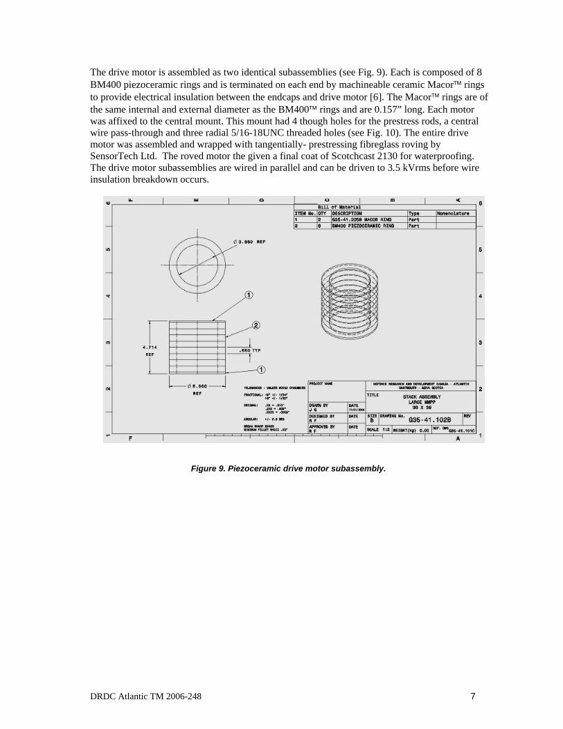
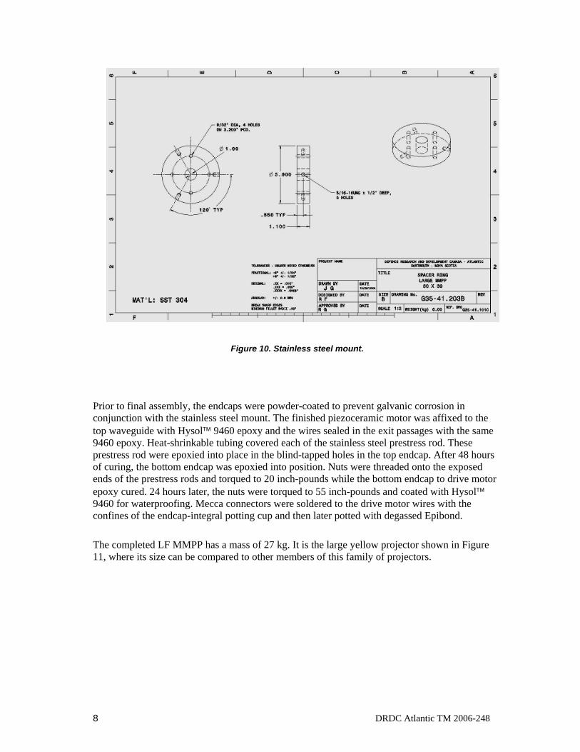
The drive motor is assembled as two identical subassemblies (see Fig. 9). Each is composed of 8 BM400 piezoceramic rings and is terminated on each end by machineable ceramic Macor™ rings to provide electrical insulation between the endcaps and drive motor [6]. The Macor™ rings are of the same internal and external diameter as the BM400™ rings and are 0.157” long. Each motor was affixed to the central mount. This mount had 4 though holes for the prestress rods, a central wire pass-through and three radial 5/16-18UNC threaded holes (see Fig. 10). The entire drive motor was assembled and wrapped with tangentially- prestressing fibreglass roving by SensorTech Ltd. The roved motor the given a final coat of Scotchcast 2130 for waterproofing. The drive motor subassemblies are wired in parallel and can be driven to 3.5 kVrms before wire insulation breakdown occurs.
Figure 9. Piezoceramic drive motor subassembly.
8 DRDC Atlantic TM 2006-248
Figure 10. Stainless steel mount.
Prior to final assembly, the endcaps were powder-coated to prevent galvanic corrosion in conjunction with the stainless steel mount. The finished piezoceramic motor was affixed to the top waveguide with Hysol™ 9460 epoxy and the wires sealed in the exit passages with the same 9460 epoxy. Heat-shrinkable tubing covered each of the stainless steel prestress rod. These prestress rod were epoxied into place in the blind-tapped holes in the top endcap. After 48 hours of curing, the bottom endcap was epoxied into position. Nuts were threaded onto the exposed ends of the prestress rods and torqued to 20 inch-pounds while the bottom endcap to drive motor epoxy cured. 24 hours later, the nuts were torqued to 55 inch-pounds and coated with Hysol™ 9460 for waterproofing. Mecca connectors were soldered to the drive motor wires with the confines of the endcap-integral potting cup and then later potted with degassed Epibond.
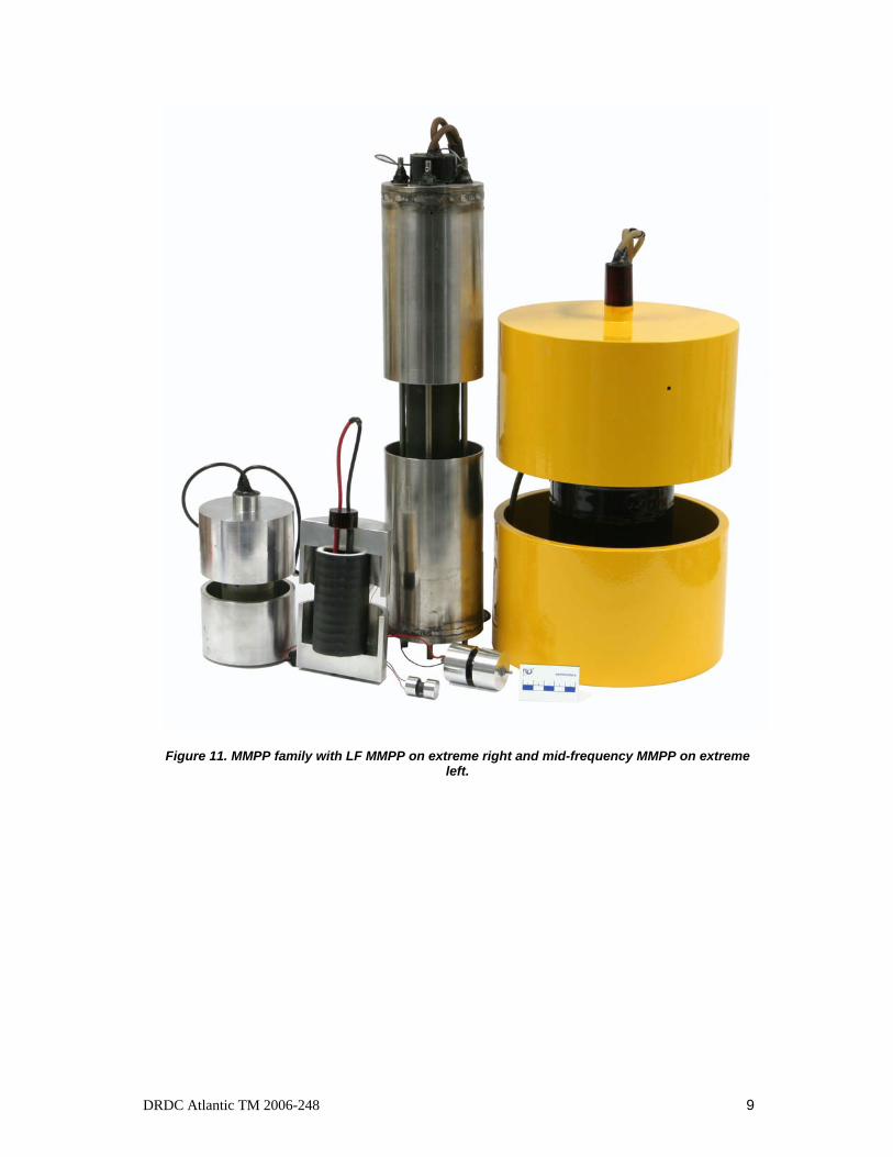
The completed LF MMPP has a mass of 27 kg. It is the large yellow projector shown in Figure 11, where its size can be compared to other members of this family of projectors.
DRDC Atlantic TM 2006-248 9
Figure 11. MMPP family with LF MMPP on extreme right and mid-frequency MMPP on extreme left.

10 DRDC Atlantic TM 2006-248
4. Testing
The transmitting voltage response (TVR) of the LF MMPP was measured at DRDC Atlantic’s acoustic calibration barge. The LF MMPP was lowered into the water to a depth of 15m and TVR’s were carried out at approximately 120 Vrms from 500 Hz-20 kHz. Broadside and endfire response comparisons between MAVART predictions and the measurements can be seen in figure 12 and figure 13. Both frequency and amplitude of the projectors’ TVR’s up to 15 kHz reflected those of the MAVART prediction quite well. Amplitude variation in the broadside response at discrete frequencies is indicative of damping or diminished piezoelectric strain in the drive motor. The broadside frequency agreement is quite good to near 12 kHz. Above this frequency, low mesh density or projector alignment during calibration may explain variations. The endfire comparison does not include the effects of the presence of wires and potting on the projector’s endcap, which could explain variation in agreement above 8 kHz.
0 2000 4000 6000 8000 10000 12000 14000 16000 18000 2000080
85
90
95
100
105
110
115
120
125
130
135
140
145
150
TVR
(dB
re 1μP
a/V
rms
@ 1
m)
Frequency (Hz)
Measured TVR MAVART prediction
Figure 12. LF MMPP broadside MAVART prediction to measurement comparison.
DRDC Atlantic TM 2006-248 11
0 2000 4000 6000 8000 10000 12000 14000 16000 18000 20000
80
90
100
110
120
130
140
150
TVR
(dB
re 1μP
a/Vr
ms
@ 1
m)
Frequency (Hz)
Measurement MAVART prediction
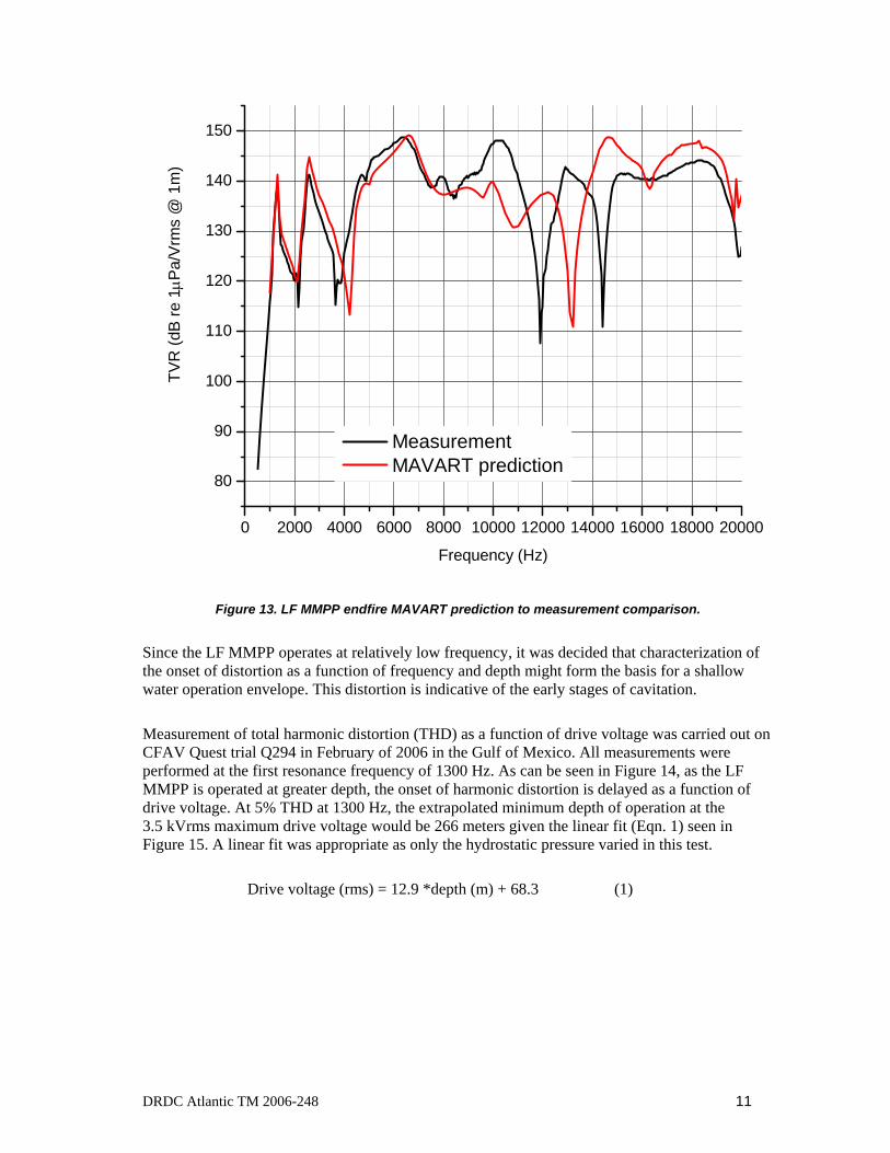
Figure 13. LF MMPP endfire MAVART prediction to measurement comparison.
Since the LF MMPP operates at relatively low frequency, it was decided that characterization of the onset of distortion as a function of frequency and depth might form the basis for a shallow water operation envelope. This distortion is indicative of the early stages of cavitation.
Measurement of total harmonic distortion (THD) as a function of drive voltage was carried out on CFAV Quest trial Q294 in February of 2006 in the Gulf of Mexico. All measurements were performed at the first resonance frequency of 1300 Hz. As can be seen in Figure 14, as the LF MMPP is operated at greater depth, the onset of harmonic distortion is delayed as a function of drive voltage. At 5% THD at 1300 Hz, the extrapolated minimum depth of operation at the 3.5 kVrms maximum drive voltage would be 266 meters given the linear fit (Eqn. 1) seen in Figure 15. A linear fit was appropriate as only the hydrostatic pressure varied in this test.
Drive voltage (rms) = 12.9 *depth (m) + 68.3 (1)

12 DRDC Atlantic TM 2006-248
0 100 200 300 400 500 600 700 800 900 1000
0
5
10
15
20
25
30
THD
(%)
Drive Voltage (rms)
2.4 meters 3.4 meters 5.4 meters 10.4 meters 50.4 meters
Figure 14. Total harmonic distortion as a function of drive voltage and depth.
0 10 20 30 40 500
100
200
300
400
500
600
700
800
5% THD threshold Linear fit
Driv
e vo
ltage
(rm
s)
Depth (m)
Figure 15. Linear fit of 5% THD points at various depths.
DRDC Atlantic TM 2006-248 13
5. Conclusion The LF MMPP is shown to be a low frequency version of the original mid-frequency MMPP and MAVART predictions of performance were consistent with measurements taken on the assembled prototypes.
Given the essentially free-flooding nature of the MMPP design, the LF MMPP could be employed to very great depth. With a reasonable 1 kVrms drive voltage, the LF MMPP can generate broadside source levels greater than 182 dB re 1 μPa @ 1m from 1.2 to 13 kHz. Full power operation of the LF MMPP is restricted to 3.5 kVrms to prevent electrical arc-over. The LF MMPP must be operated at depths greater than 266 meters at full power to prevent total harmonic distortion of greater than 5%.
With such broadband response beginning at low frequency, the LF MMPP has a role in underwater communications and sonar. Experimentation with LF MMPP in broadband communications will include spectral and phase compensation and power delivery optimization. Further broadband testing is planned for the near future for this promising transducer.
14 DRDC Atlantic TM 2006-248
6. References
1. US Patent 6,584,039, C.J. Purcell and R.A.G. Fleming, “Multi-Mode Pipe Projector”, (2003)
2. D.F. Jones and J. Lindberg, Recent Transduction Developments in Canada and the United States, Proceedings of the Institute of Acoustics, 17 (3).
3. R.A.G. Fleming, Wideband Sonar Pipe Projectors, Dalhousie University Master of Science Thesis, (2001).
4. Purcell C.J. et.al., Modelling, Analysis & Prototyping for Rapid Manufacturing, 2001 Mathematica Developer Conference, http://library.wolfram.com/infocenter/Conferences/4015/
5. Corning Industries Inc., Specialty Materials, PO Box 189, 24 east Brookfield Road, North Brookfield Massachusetts, 01535 USA.
DRDC Atlantic TM 2006-248 15
List of symbols/abbreviations/acronyms/initialisms
DND Department of National Defence
DRDC Defence Research and Development Canada
MMPP Multi-mode pipe projector
LF MMPP low frequency multi-mode pipe projector
MAVART Model to analyze the vibration and acoustic radiation of transducers
Hz hertz
TVR transmitting voltage response
THD total harmonic distortion
16 DRDC Atlantic TM 2006-248
Distribution list
Document No.: DRDC Atlantic TM2006-248
LIST PART 1: Internal Distribution by Centre:
1 Richard Fleming 1 Mark Trevorrow 1 John Fawcett 1 Christopher Purcell 1 David Hazen Head/TD 5 DRDC Atlantic Library
10 TOTAL LIST PART 1
LIST PART 2: External Distribution by DRDKIM 1 John Sones, DMSS 6-6 1 Maj. Scott Campbell, DAEPM 5-2 1 DRDKIM
3 TOTAL LIST PART 2
13 TOTAL COPIES REQUIRED
DRDC Atlantic mod. May 02
DOCUMENT CONTROL DATA (Security classification of title, body of abstract and indexing annotation must be entered when the overall document is classified)
1. ORIGINATOR (the name and address of the organization preparing the document. Organizations for whom the document was prepared, e.g. Centre sponsoring a contractor's report, or tasking agency, are entered in section 8.)
Defence R&D Canada – Atlantic PO Box 1012 Dartmouth, NS, Canada B2Y 3Z7
2. SECURITY CLASSIFICATION (overall security classification of the document
including special warning terms if applicable).
UNCLASSIFIED
3. TITLE (the complete document title as indicated on the title page. Its classification should be indicated by the appropriate abbreviation (S,C,R or U) in parentheses after the title).
Low Frequency Multi-Mode Pipe Projector
4. AUTHORS (Last name, first name, middle initial. If military, show rank, e.g. Doe, Maj. John E.)
Fleming, Richard A.G.
5. DATE OF PUBLICATION (month and year of publication of document)
November 2006
6a. NO. OF PAGES (total containing information Include Annexes, Appendices, etc).
16 (approx.)
6b. NO. OF REFS (total cited in document)
5
7. DESCRIPTIVE NOTES (the category of the document, e.g. technical report, technical note or memorandum. If appropriate, enter the type of
report, e.g. interim, progress, summary, annual or final. Give the inclusive dates when a specific reporting period is covered).
Technical memorandum
8. SPONSORING ACTIVITY (the name of the department project office or laboratory sponsoring the research and development. Include address).
Defence R&D Canada – Atlantic PO Box 1012 Dartmouth, NS, Canada B2Y 3Z7
9a. PROJECT OR GRANT NO. (if appropriate, the applicable research
and development project or grant number under which the document was written. Please specify whether project or grant).
11cy04 (TIF) L105
9b. CONTRACT NO. (if appropriate, the applicable number under which the document was written).
10a ORIGINATOR'S DOCUMENT NUMBER (the official document
number by which the document is identified by the originating activity. This number must be unique to this document.)
DRDC Atlantic TM 2006-248
10b OTHER DOCUMENT NOs. (Any other numbers which may be assigned this document either by the originator or by the sponsor.)
11. DOCUMENT AVAILABILITY (any limitations on further dissemination of the document, other than those imposed
by security classification) ( X ) Unlimited distribution ( ) Defence departments and defence contractors; further distribution only as approved ( ) Defence departments and Canadian defence contractors; further distribution only as approved ( ) Government departments and agencies; further distribution only as approved ( ) Defence departments; further distribution only as approved ( ) Other (please specify):
12. DOCUMENT ANNOUNCEMENT (any limitation to the bibliographic announcement of this document. This will normally correspond to the Document
Availability (11). However, where further distribution (beyond the audience specified in (11) is possible, a wider announcement audience may be selected).
DRDC Atlantic mod. May 02
13. ABSTRACT (a brief and factual summary of the document. It may also appear elsewhere in the body of the document itself. It is highly desirable that the abstract of classified documents be unclassified. Each paragraph of the abstract shall begin with an indication of the security classification of the information in the paragraph (unless the document itself is unclassified) represented as (S), (C), (R), or (U). It is not necessary to include here abstracts in both official languages unless the text is bilingual).
(U) The multi-mode pipe projector (MMPP) is a recently patented sonar projector capable of very wide bandwidth. The projector generates this bandwidth with an optimized approach to overlapping numerous drive motor and waveguide resonances. The low frequency MMPP (LF MMPP) was developed by scaling the original 3-35 kHz MMPP’s dimensions by 5/2 and optimizing for an available piezoelectric ring size for a projected bandwidth of 1.3-13 kHz. A single prototype was built and tested and its bandwidth mirrored the finite element predictions for performance. Deep water testing revealed distortion-limited shallow-water performance, which will require the LF MMPP to be operated at a depth of more than 266 m at high drive voltage.
14. KEYWORDS, DESCRIPTORS or IDENTIFIERS (technically meaningful terms or short phrases that characterize a document and could be helpful in cataloguing the document. They should be selected so that no security classification is required. Identifiers, such as equipment model designation, trade name, military project code name, geographic location may also be included. If possible keywords should be selected from a published thesaurus. e.g. Thesaurus of Engineering and Scientific Terms (TEST) and that thesaurus-identified. If it not possible to select indexing terms which are Unclassified, the classification of each should be indicated as with the title). sonar projector transducer broadband low-frequency

This page intentionally left blank.