low voltage acti 9 - docs-emea.rs-online.com · bs en 61439-3 iec 61439-3 acti9 isobar b type...
TRANSCRIPT

Acti 9the efficiency you deserve
Low voltage
Ordering guide

Ordering references
Acti9 Distribution boards 22
Introduction 22
A type 24
B type 28
Acti9 miniature circuit breakers 36
iC60H 1,2,3,4 pole Mcbs 36
iC60H single pole wide RCBO 40
iC60 Vigibloc 42
iC60 Auxiliaries 45
iC60 Accessories 52
Residual Current Circuit Breakers 56
iID RCCB 56
21

A type single phase boardsActi 9 Isobar the safest distribution board
b Fully type tested conditional short circuit rating of 16kA to BS EN 61439-3 b High performance MCB 10kA BS EN 60898 15kA BS EN 60947-2 in B, C or D
curve single and double pole b 125A busbar rating b Isobar disconnection to BS EN 60947-3 ensuring unused outgoing ways are
isolated b Option of switching outgoing neutral on all boards using distributed neutral kit b Terminal block for feeding up to 100A b Range of incomers: switch disconnectors, residual current devices, terminal
blocks b Single pole RCBO for new or retrofit maintaining device density b Full range of device accessories and auxiliaries b Knockouts for cable gland and conduit mixed to suit the installation needs without
loss of space b Split metering options
Standard, meter ready, split metered and multi service options
Fully encapsulated busbar system
conversion of any outgoing way into neutral
Fully shroudedconnections whenmain switch is fitted
Fully shroudedneutral bars
Wide range of add-onauxiliaries, e.g. shunttrips, auxiliary switches,add-on earth leakagemodules, etc
Non removable interlock to prevent operation unless an outgoing device is fitted
wide range of incomers
22

B Type 3 phase distributionActi 9 Isobar the safest distribution board
b Fully type tested conditional short circuit rating of 25kA to BS EN 61439-3 b High performance MCB 10kA BS EN 60898 15kA BS EN 60947-2 in B, C or D
curve 1, 2, 3, 4 pole b 250A busbar rating b Isobar disconnection to BS EN 60947-3 ensuring unused outgoing ways are
isolated b Option of switching outgoing neutral on all boards using distributed neutral kit b Terminal block for feeding up to 100A b Range of incomers: switch disconnectors, residual current devices, terminal
blocks, mccb b Single pole RCBO for new or retrofit maintaining device density b Full range of device accessories and auxiliaries b Knockouts for cable gland and conduit mixed to suit the installation needs without
loss of space b Removable insulated pan assembly b Fully shrouded neutral b Split neutral bars b Removable gland plates b Optional metering, dual supply, surge protection and contactor on incoming b Metered extension enclosures
Standard, meter ready, split metered and multi service options
Fully encapsulated busbar system
conversion of any outgoing way into neutral
Fully shroudedconnections whenmain switch is fitted
Fully shroudedneutral bars
Wide range of add-onauxiliaries, e.g. shunttrips, auxiliary switches,add-on earth leakagemodules, etc
Non removable interlock to prevent operation unless an outgoing device is fitted
wide range of incomers
23

b Acti9 Isobar is a complete range of single and 3 phase distribution boards for commercial and industrial applications
v Standard distribution boards up to 24 ways v Multi service distribution boards up to 24 ways v Dual incomer distribution boards up to 24 ways v Split load distribution boards up to 24 ways v Split metered distribution boards up to 20 ways v Any outgoing way can be converted to switch the Neutral
Alternating current (AC) 50Hzwithstand 110v 230/240v
conditional 25kA 25kA
unconditional 25kA/50mS 25kA/50mS17kA/200mS 17kA/200mS
Direct current (DC) 24v 48v
unconditional 25kA/50mS 25kA/50mS
BS EN 61439-3 IEC 61439-3
Acti9 Isobar A type distribution boards
Acti 9 Isobar the safest distribution board
Catalogue numbersActi9 Isobar Standard distribution boards busbar rating 125amp
incomers not included No of SP ways No of DP waysSEA9AN2 2 1SEA9AN6 6 3SEA9AN10 10 5SEA9AN14 14 7SEA9AN18 18 9SEA9AN27 27 12
Acti9 Isobar Multi service distribution boards busbar rating 125amp
incomers not included No of SP ways Useable DIN rail 9mm ways
SEA9AN1008MS 10 8SEA9AN1016MS 10 16SEA9AN1432MS 14 32SEA9AN616MS 6 16SEA9AN624MS 6 24
Acti9 Isobar Split load distribution boards busbar rating 125amp
incomers not included Unprotected way Protected waysSEA9AN106SL 10 6SEA9AN610SL 6 10SEA9AN66SL 6 6
24

Acti9 Isobar A type distribution boards
Acti 9 Isobar the safest distribution board
Technical data Standard, Meter ready, Split metered Acti9 IsobarMain characteristics 110v 230/240v
According to BE EN 61439-3
Withstand conditional 25kA 25kAunconditional 25kA/50mS 25kA/50mS
17kA/200mS 17kA/200mSinsulation voltage (Ui)Pollution degreeRated inpulse withstand voltage (Uimp)Current rating (A) direct connection 125
Switch disconnector 125 DIN mounted Power switchRCCB 100sensetivites (mA) 30, 100, 300, 300TD
Degree of protection External IP30(IEC 60529) Internal IP20Endurance (O-C) Isobar switch disconnector
3000
Overvoltage category IVOperating temperature -35 to +700CStorage teperature -40 to +800C
ConnectionsRating tightening torque Copper lugs cables bare device125 amp b 50mm DIN switch disconnector125 amp b 50mm Terminal block100 amp b 35mm RCCB
125 amp rated bars with non removable covers
fully insulated construction
padlockable in the off position only
switch disconnector for each outgoing way
Acti9 Isobar Dual supply distribution boards busbar rating 125amp
incomers not included Unprotected way Protected waysSEA9AN106DS 10 6SEA9AN26DS 2 6SEA9AN66DS 6 6
Acti9 Isobar Split metered distribution boards busbar rating 125amp direct connected metersincoming switch disconnector included
No of SP ways No of DP ways
SEA9AN6S6 40A direct connected 6 6SEA9AN10S10 63A direct connected 10 10
25

Acti9 Isobar A type distribution boards
Acti 9 Isobar the safest distribution board
Weight (kG) - Dimensions (mm)
Standard Multi service Split load Dual Incomer Split metered kG Height width depth2 way b b b b 1.8 300 200 1176 way b b b b 2.5 300 273 11710 way b b 2 - 6 b 3.0 300 345 11714 way 6 - 16, 10 - 8 5 - 6 6 - 6 b 4.8 300 417 11718 way 6 - 24, 10 - 16, 14 - 8 5 - 10, 9 - 6 10 - 6 6 - 6 5.7 300 489 11727 way 14 - 32 b b 10 - 10 8.9 530 417 117
Incomers
Switch disconnector rating (A) no of polesSEA91252 125 2
DIN rail only enclosures
Reference Description number of rows dimensionsSEA9DE16 8 SP way module enclosure 1 SEA9AN6SEA9DE24 12 SP way module enclosure 1 SEA9AN10SEA9DE32 16 SP way module enclosure 1 SEA9AN14SEA9DE40 20 SP way module enclosure 1 SEA9AN18SEA9DE64 32 SP way module enclosure 2 SEA9AN27
Residual current circuit breaker 230/240vAC rating (A) no of poles
sensitivity (mA)SEA9R41263 30 63 2SEA9R12263 100 63 2SEA9R44263 300 63 2SEA9211280 30 80 2SEA9R12280 100 80 2SEA9R14280 300 80 2SEA9R15280 300 TD 80 2SEA9R11291 30 100 2SEA9R12291 100 100 2SEA9R14291 300 100 2SEA9R15291 300 TD 100 2
Terminal block rating (A) no of polesSEA9TB1252 125 2
26

Incomers
Switch disconnector rating (A) no of polesSEA91252 125 2
Acti9 Isobar A type distribution boards
Acti 9 Isobar the safest distribution board
AccessoriesFlush mounting kits
Reference no of waysSEA9AN6FK Flush mounting kit 6SEA9AN10FK Flush mounting kit 10SEA9AN14FK Flush mounting kit 14SEA9AN18FK Flush mounting kit 18
Distributed neutral kitsReference no of waysSEA9NA6 Distributed neut'l for 6 way SP+N 6SEA9NA10 Distributed neut'l for 10 way SP+N 10SEA9NA14 Distrib'd neut'l for 14 way SP+N 14SEA9NA18 Distrib'd neut'l for 18 way SP+N 18SEA9NA27 Distrib'd neut'l for 27 way SP+N 27SEA9NKIT Phase to neutral conversion kit (pack
4)Reference Description
SEA9BL Door lockSEA9PD Padlock kit for doorSEA9BP Blank poleSEA9BP25 Pack of 25 x 5 pole fillerSEA9BP5 single 5 pole fillerSEA9TB1001 100 amp terminal block 1 poleSEA9ANWL SP&N LABELS
Acti9 Isobar A type pan assemblies
Reference no of ways height width depthSEA9AN6PS supplied without distributed neutral 6 202 200 87SEA9AN10PS supplied without distributed neutral 10 202 272 87SEA9AN14PS supplied without distributed neutral 14 202 344 87SEA9AN18PS supplied without distributed neutral 18 202 416 87
27

b Acti9 Isobar is a complete range of single and 3 phase v distribution boards for commercial and industrial v applications v Standard distribution boards up to 24 ways v Meter ready distribution boards up to 24 ways v Split metered distribution boards up to 22 ways v Any outgoing way can be converted to switch the Neutral
Alternating current (AC) 50Hzwithstand 230/240v 400v 415v
conditional 25kA 25kA 25kA
unconditional 25kA/50mS 25kA/50mS 25kA/50mS17kA/200mS 17kA/200mS 17kA/200mS
Direct current (DC)
24v 48v
unconditional 25kA/50mS 25kA/50mS
BS EN 61439-3 IEC 61439-3
Acti9 Isobar B type distribution boards
Acti 9 Isobar the safest distribution board
Catalogue numbersActi9 Isobar Standard distribution boards busbar rating 250amp
No of TP ways No of SP ways No of DP waysSEA9BN4 4 12 6SEA9BN6 6 18 9SEA9BN8 8 24 12SEA9BN12 12 36 18SEA9BN16 16 48 24SEA9BN18 18 54 26SEA9BN24 24 72 36
Acti9 Isobar Meter ready distribution boards busbar rating 250amp
No of TP ways No of SP ways No of DP waysSEA9BN6M 6 18 9SEA9BN8M 8 24 12SEA9BN12M 12 36 18SEA9BN16M 16 48 24SEA9BN18M 18 54 26SEA9BN24M 24 72 36
28

Acti9 Isobar Split metered* distribution boards busbar rating 125 amp
lower pan assembly
No of TP ways
No of SP ways upper pan assembly
No of TP ways
No of SP ways
SEA9BN1254S8 6 18 8 24SEA9BN1258S8 8 24 8 24SEA9BN12512S8 14 42 8 24SEA9BN12514S6 16 48 6 18SEA9BN12516S4 18 54 4 12
Acti9 Isobar Split metered* distribution boards busbar rating 250 amp
lower pan assembly
No of TP ways
No of SP ways upper pan assembly
No of TP ways
No of SP ways
SEA9BN2504S8 6 18 8 24SEA9BN2508S8 8 24 8 24SEA9BN25012S8 14 42 8 24SEA9BN25014S6 16 48 6 18SEA9BN25016S4 18 54 4 12
250 amp rated bars with non removable covers
fully insulated construction
padlockable in the off position only
interlocked switch disconnector for each outgoing way
*MID 3 Phase kWh kit Modbus communications and pulsed output
Acti 9 Isobar the safest distribution board
Acti9 Isobar B type distribution boards
29
Acti9 Isobar B type distribution boards
Acti 9 Isobar the safest distribution board
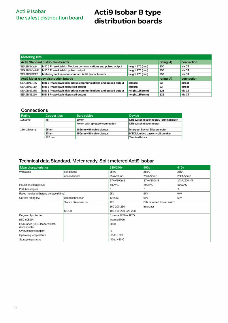
Metering kits
Acti9 Standard distribution boards rating (A) connectionSEA9BNKWH MID 3 Phase kWh kit Modbus communications and pulsed output height 270 (mm) 250 via CTSEA9BNKWHP MID 3 Phase kWh kit pulsed output height 270 (mm) 250 via CTSEA9BNMETE Metering enclosure for standard Acti9 Isobar boards height 270 (mm) 250 via CT
Acti9 Meter ready distribution boards rating (A) connectionSEA9BN3155 MID 3 Phase kWh kit Modbus communications and pulsed output integral 63 directSEA9BN3110 MID 3 Phase kWh kit pulsed output integral 63 directSEA9BN3255 MID 3 Phase kWh kit Modbus communications and pulsed output height 135 (mm) 125 via CTSEA9BN3210 MID 3 Phase kWh kit pulsed output height 135 (mm) 125 via CT
Technical data Standard, Meter ready, Split metered Acti9 IsobarMain characteristics 230/240v 400v 415v
Withstand conditional 25kA 25kA 25kAunconditional 25kA/50mS 25kA/50mS 25kA/50mS
17kA/200mS 17kA/200mS 17kA/200mSinsulation voltage (Ui) 500vAC 500vAC 500vACPollution degree 3 3 3Rated inpulse withstand voltage (Uimp) 6kV 6kV 6kVCurrent rating (A) direct connection 125/250 6kV 6kV
Switch disconnector 125 DIN mounted Power switch160-200-250 Interpact
MCCB 100-160-200-225-250Degree of protection External IP30 or IP55(IEC 60529) Internal IP20Endurance (O-C) Isobar switch disconnector
3000
Overvoltage category IVOperating temperature -35 to +700CStorage teperature -40 to +800C
ConnectionsRating Copper lugs Bare cables Device
125 amp 18 50mm DIN switch disconnector/Terminal block70mm with spreader connection DIN switch disconnector
160 -250 amp 95mm 185mm with cable clamps Interpact Switch Disconnector95mm 185mm with cable clamps NSX Moulded case circuit breaker120 mm Terminal block
30

Acti 9 Isobar the safest distribution board
Acti9 Isobar B type distribution boards
Main characteristics Acti9 Isobar IP55According to BE EN 61439-3 230/240v 400v 415v
Withstand conditional 25kA 25kA 25kAunconditional 25kA/50mS 25kA/50mS 25kA/50mS
17kA/200mS 17kA/200mS 17kA/200mSinsulation voltage (Ui) 500vACPollution degree 3Rated inpulse withstand voltage (Uimp) 6kVCurrent rating (A) 100ADegree of protection External IP30 or IP55(IEC 60529) Internal IP20Endurance (O-C) Isobar switch disconnector
3000
Overvoltage category IVOperating temperature -35 to +700CStorage teperature -40 to +800C
Catalogue numbersActi9 Isobar Standard IP55 distribution boards busbar rating 125amp steel door
No of TP ways No of SP ways No of DP waysSEA9BN6HDGR 6 18 9SEA9BN8HDGR 8 24 12SEA9BN12HDGR 12 36 18SEA9BN16HDGR 16 48 24
Acti9 Isobar Standard IP55 distribution boards busbar rating 125amp transparent door
No of TP ways No of SP ways No of DP waysSEA9BN6HDGK 6 18 9SEA9BN8HDGK 8 24 12SEA9BN12HDGK 12 36 18SEA9BN16HDGK 16 48 24
Weight (kG) - Dimensions (mm)
Standard Meter ready Split load kG Height width depth4 way n n 9 484 470 1396 way 6 way n 10.5 484 470 1388 way 6 way n 11 538 470 13812 way 12 way n 13.5 700 470 13916 way 16 way n 16 808 470 13918 way 18 way n 16.2 862 470 13924 way 24 way n 22 1024 139n n all versions 28 1294 470 139
250 amp incoming section
4 400 470 130
IP55 kG Height width depth6 way b 32.4 650 600 3308 way b 32.9 650 600 33012 way b 40.1 800 600 33016 way b 41.4 800 600 330
31

Incommers
Switch disconnector rating (A) no of poles
Standard Meter ready
Split metered
IP55
SEA91253N 125 3P+N Int Int Int IntSEA91254 125 4 Int Int Int IntSEA9NI1603 160 3P+N Ext Ext Ext n
SEA9NI1604 160 4 Ext Ext Ext n
SEA9NI2003 200 3P+N Ext Ext Ext n
SEA9NI2004 200 4 Ext Ext Ext n
SEA9NI2254 225 4 Ext Ext Ext n
SEA9NI2503 250 3P+N Ext Ext Ext n
SEA9NI2504 250 4 Ext Ext Ext n n
Moulded Case Circuit Breaker rating (A) no of poles
Standard Meter ready
Split metered
IP55
SEA9NCB1004 70-100 4 Ext Ext Ext n
SEA9NCB1604 112-160 4 Ext Ext Ext n
SEA9NCB2004 140-200 4 Ext Ext Ext nSEA9NCB2504 175-250 4 Ext Ext Ext n
Residual current circuit breaker
sensitivity (mA)
rating (A) no of poles
Standard Meter ready
Split metered
IP55
A9R41463 30 63 4 Int Int Int IntA9R12463 100 63 4 Int Int Int IntA9R44463 300 63 4 Int Int Int IntA9R15463 300/time delayed 63 4 Int Int Int IntA9R11480 30 80 4 Int Int Int IntA9R14491 300 100 4 Int Int Int IntA9R15491 300/time delayed 100 4 Int Int Int IntSEA9NI160RCCB adjustable 160 n Ext Ext Ext n
Terminals for direct connection rating (A) no of poles
Standard Meter ready
Split metered
IP55
SEA9TB1254 125 4 Int Int Int IntSEA9NTB2504 250 4 Ext Ext Ext n
Dual source incomer rating (A) no of poles
Standard Meter ready
Split metered
IP55
SEA9NDSI *270mm enclosure 125 4 Ext Ext Ext n
Contactor incomer rating (A) no of poles
Standard Meter ready
Split metered
IP55
SEA9BN100CCI *270mm enclosure 100 4 Ext Ext Ext n
Dual metered extension enclosure rating (A) no of poles
Standard Meter ready
Split metered
IP55
SEA9BNDM160SD Interpact SD 160 4 Ext n n n
SEA9BNDM200SD Interpact SD 200 4 Ext n n n
SEA9BNDM250SD Interpact SD 250 4 Ext n n n
SEA9BNDM160M NSX MCCB 160 4 Ext n n n
SEA9BNDM200M NSX MCCB 200 4 Ext n n n
SEA9BNDM250M NSX MCCB 250 4 Ext n n n
*MID 3 Phase kWh kit Modbus communications and pulsed output
Single phasing kits rating (A) no of poles
Standard Meter ready
Split metered
IP55
SEA9125SPEV 125 4 Int Int Int IntSEA9250SPEV 250 4 Int Int Int Int
Acti9 Isobar B type distribution boards
Acti 9 Isobar the safest distribution board
Int= Internal to the distribtion boardExt = in 400mm high extension enclouseresn = not applicable
32

Top or Bottom Extension enclosures height 270 (mm) not applicableSwitch disconnector Description
SEA9BNEXN plain front cover for additional wiring spaceSEA9BNEX034N mounting of DIN devices, overall door and cutout
for 17 x 18mm polesSEA9BNEXA15N single phase add on distribution board 15 way
Side Extension enclosuresReference Description No of rows total 18mm
SP waysdimensions
SEA9N4SXS Slotted front cover + overall door 2 34 SEA9BN4SEA9N8SXS Slotted front cover + overall door 2 34 SEA9BN8SEA9N12SXS Slotted front cover + overall door 3 51 SEA9NB12SEA9N16SXS Slotted front cover + overall door 4 68 SEA9NB16SEA9N24SXS Slotted front cover + overall door 5 85 SEA9NB24SEA9N4SXP Plain front cover+ overall door 2 34 SEA9BN4SEA9N8SXP Plain front cover+ overall door 2 34 SEA9BN8SEA9N12SXP Plain front cover+ overall door 3 51 SEA9NB12SEA9N16SXP Plain front cover+ overall door 4 68 SEA9NB16SEA9N24SXP Plain front cover+ overall door 5 85 SEA9NB24
Accessories
Reference Description Reference Description
SEA9BL Door lock SEA9NB4 Distributed neut'l for 4 way TP+NSEA9PD Padlock kit for door SEA9NB6 Distributed neut'l for 6 way TP+NSEA9NEK1 Extra earth terminal bar 14 hole SEA9NB8 Distributed neut'l for 8 way TP+NSEA9NEK2 Extra earth terminal bar 20 hole SEA9NB12 Distrib'd neut'l for 12 way TP+NSEA9NEK3 Extra earth terminal 26 hole SEA9NB16 Distrib'd neut'l for 16 way TP+N
SEA9NB18 Distrib'd neut'l for 18 way TP+NSEA9BN63SPL split load lit 63 amp SEA9NB24 Distrib'd neut'l for 24 way TP+NSEA9BNSJKN Side joining kit SEA9NKIT Phase to neutral conversion kit
(pack 4)SEA9BNTJKA Top/bottom joining kit for enc/ext/encSEA9BNTJKB Top bottom kit replacing gland plateSEA9BNTJKN Joining kit B board top/bottomSEA9BP Blank poleSEA9BP25 Pack of 25 x 5 pole fillerSEA9BP5 single 5 pole fillerSEA9TB1001 100 amp terminal block 1 poleSEA9BNBCE7 clean earth B boards 7 holeSEA9BNBCE13 clean earth B boards 13 holeSEA9BNBCE25 Clean earth B boards 25 holeSEA9BNWL TP&N LABELS
Acti 9 Isobar the safest distribution board
Acti9 Isobar B type distribution boards
33

Pan assemblies - replacement for Acti9 Isobar and Isobar 4c distribution boardsReference DescriptionSEA9BN4P B board replacement pan assembleySEA9BN6P B board replacement pan assembleySEA9BN8P B board replacement pan assemblySEA9BN12P B board replacement pan assembleySEA9BN16P B board replacement pan assembleySEA9BN18P B board replacement pan assembleySEA9BN24P b board replacement pan assembley
Pan assemblies - for switchboard mounting supplied with earths and neutral, phase coloured Isobar switch disconnectors
Reference DescriptionSEA9BN4E pan assembly 4 way TP+ earth and neutralSEA9BN6E pan assembly 6 way TP+ earth and neutralSEA9BN8E pan assembly 8 way TP+ earth and neutralSEA9BN12E pan assembly 12 way TP+ earth and neutralSEA9BN16E pan assembly 16 way TP+ earth and neutralSEA9BN18E pan assembly 18 way TP+ earth and neutralSEA9BN24E pan assembly 24 way TP+ earth and neutral
Pan assemblies - for switchboard mounting supplied with earths and neutral, black Isobar switch disconnectors
Reference DescriptionSEA9BN4PEV pan assembly 4 way TP+ earth and neutralSEA9BN6PEV pan assembly 6 way TP+ earth and neutralSEA9BN8PEV pan assembly 8 way TP+ earth and neutralSEA9BN12PEV pan assembly 12 way TP+ earth and neutralSEA9BN16PEV pan assembly 16 way TP+ earth and neutralSEA9BN18PEV pan assembly 18 way TP+ earth and neutralSEA9BN24PEV pan assembly 24 way TP+ earth and neutral
Pan assemblies - 3 phase without distributed neutral, supplied fitted on a mounting plateReference DescriptionSEA9BN4TN 4 TP&N way panel fixing pan assmSEA9BN6TN 6 TP&N way panel fixing pan assmSEA9BN8TN 8 TP&N way panel fixing pan assmSEA9BN12TN 12 TP&N way panel fixing pan assmSEA9BN16TN 16 TP&N way panel fixing pan assmSEA9BN18TN 18 TP&N way panel fixing pan assmSEA9BN24TN 24 TP&N way panel fixing pan assm
Pan assemblies - 3 phase without distributed neutral, supplied without mounting plateReference DescriptionSEA9BN4PS Pan Assembley 4 way TP&NSEA9BN6PS Pan Assembley 6 way TP&NSEA9BN8PS Pan Assembley 8 way TP&NSEA9BN12PS Pan Assembley 12 way TP&NSEA9BN16PS Pan Assembley 16 way TP&NSEA9BN18PS Pan Assembley 18 way TP&NSEA9BN24PS Pan Assembley 24 way TP&N
Acti9 Isobar B type distribution boards
Acti 9 Isobar the safest distribution board
34

Pan assemblies - replacement for Acti9 Isobar and Isobar 4c distribution boardsReference DescriptionSEA9BN4P B board replacement pan assembleySEA9BN6P B board replacement pan assembleySEA9BN8P B board replacement pan assemblySEA9BN12P B board replacement pan assembleySEA9BN16P B board replacement pan assembleySEA9BN18P B board replacement pan assembleySEA9BN24P b board replacement pan assembley
Pan assemblies - for switchboard mounting supplied with earths and neutral, phase coloured Isobar switch disconnectors
Reference DescriptionSEA9BN4E pan assembly 4 way TP+ earth and neutralSEA9BN6E pan assembly 6 way TP+ earth and neutralSEA9BN8E pan assembly 8 way TP+ earth and neutralSEA9BN12E pan assembly 12 way TP+ earth and neutralSEA9BN16E pan assembly 16 way TP+ earth and neutralSEA9BN18E pan assembly 18 way TP+ earth and neutralSEA9BN24E pan assembly 24 way TP+ earth and neutral
Pan assemblies - for switchboard mounting supplied with earths and neutral, black Isobar switch disconnectors
Reference DescriptionSEA9BN4PEV pan assembly 4 way TP+ earth and neutralSEA9BN6PEV pan assembly 6 way TP+ earth and neutralSEA9BN8PEV pan assembly 8 way TP+ earth and neutralSEA9BN12PEV pan assembly 12 way TP+ earth and neutralSEA9BN16PEV pan assembly 16 way TP+ earth and neutralSEA9BN18PEV pan assembly 18 way TP+ earth and neutralSEA9BN24PEV pan assembly 24 way TP+ earth and neutral
Pan assemblies - 3 phase without distributed neutral, supplied fitted on a mounting plateReference DescriptionSEA9BN4TN 4 TP&N way panel fixing pan assmSEA9BN6TN 6 TP&N way panel fixing pan assmSEA9BN8TN 8 TP&N way panel fixing pan assmSEA9BN12TN 12 TP&N way panel fixing pan assmSEA9BN16TN 16 TP&N way panel fixing pan assmSEA9BN18TN 18 TP&N way panel fixing pan assmSEA9BN24TN 24 TP&N way panel fixing pan assm
Pan assemblies - 3 phase without distributed neutral, supplied without mounting plateReference DescriptionSEA9BN4PS Pan Assembley 4 way TP&NSEA9BN6PS Pan Assembley 6 way TP&NSEA9BN8PS Pan Assembley 8 way TP&NSEA9BN12PS Pan Assembley 12 way TP&NSEA9BN16PS Pan Assembley 16 way TP&NSEA9BN18PS Pan Assembley 18 way TP&NSEA9BN24PS Pan Assembley 24 way TP&N
Pan assemblies - accessoriesReference Description
SEA9BINCKIT 250 amp incoming terminal block
Acti 9 Isobar the safest distribution board
Acti9 Isobar B type distribution boards
35
36
iC60H circuit breakers (curve B, C, D)
Protection Circuit protection
(1) VDE approved only.
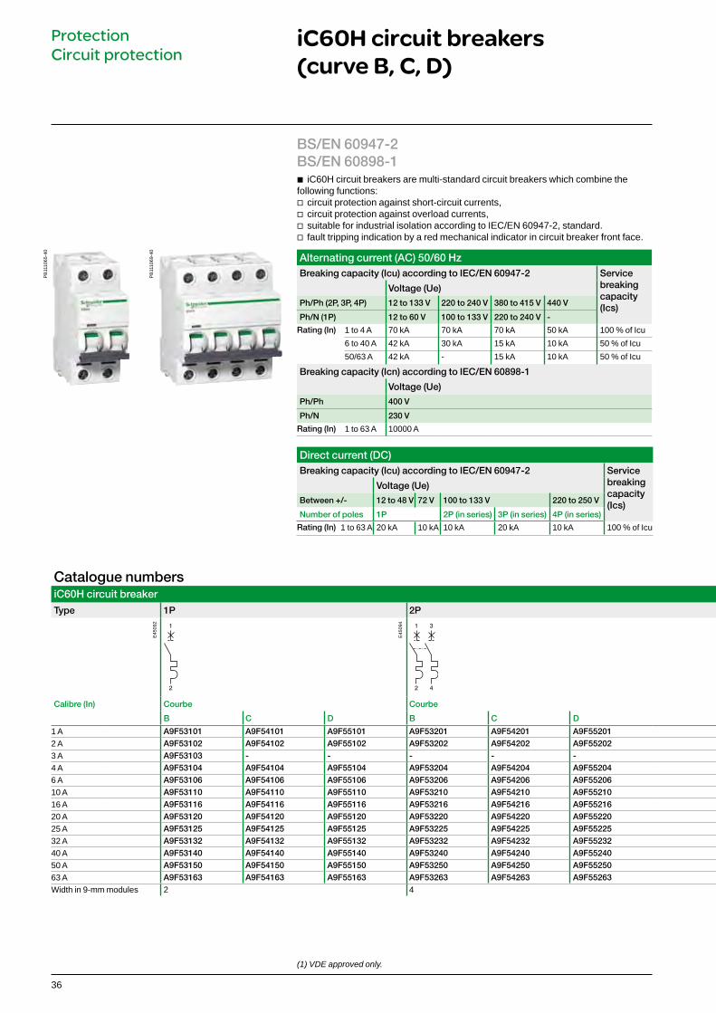
b iC60H circuit breakers are multi-standard circuit breakers which combine the following functions:
v circuit protection against short-circuit currents, v circuit protection against overload currents, v suitable for industrial isolation according to IEC/EN 60947-2, standard. v fault tripping indication by a red mechanical indicator in circuit breaker front face.
Alternating current (AC) 50/60 HzBreaking capacity (Icu) according to IEC/EN 60947-2 Service
breaking capacity (Ics)
Voltage (Ue)
Ph/Ph (2P, 3P, 4P) 12 to 133 V 220 to 240 V 380 to 415 V 440 V
Ph/N (1P) 12 to 60 V 100 to 133 V 220 to 240 V -
Rating (In) 1 to 4 A 70 kA 70 kA 70 kA 50 kA 100 % of Icu6 to 40 A 42 kA 30 kA 15 kA 10 kA 50 % of Icu 50/63 A 42 kA - 15 kA 10 kA 50 % of Icu
Breaking capacity (Icn) according to IEC/EN 60898-1
Voltage (Ue)
Ph/Ph 400 V
Ph/N 230 V
Rating (In) 1 to 63 A 10000 A
Direct current (DC) Breaking capacity (Icu) according to IEC/EN 60947-2 Service
breaking capacity (Ics)
Voltage (Ue)
Between +/- 12 to 48 V 72 V 100 to 133 V 220 to 250 V
Number of poles 1P 2P (in series) 3P (in series) 4P (in series)
Rating (In) 1 to 63 A 20 kA 10 kA 10 kA 20 kA 10 kA 100 % of Icu
BS/EN 60947-2 BS/EN 60898-1
Catalogue numbersiC60H circuit breaker
Type 1P 2P 3P 4P
1
2
1
2
3
4
1
2
3
4
5
6
1
2
3
4
5
6
7
8
Calibre (In) Courbe Courbe Courbe Courbe
B C D B C D B C D B C D
1 A A9F53101 A9F54101 A9F55101 A9F53201 A9F54201 A9F55201 A9F53301 A9F54301 A9F55301 A9F53401 A9F54401 A9F554012 A A9F53102 A9F54102 A9F55102 A9F53202 A9F54202 A9F55202 A9F53302 A9F54302 A9F55302 A9F53402 A9F54402 A9F554023 A A9F53103 - - - - - - - - - - -4 A A9F53104 A9F54104 A9F55104 A9F53204 A9F54204 A9F55204 A9F53304 A9F54304 A9F55304 A9F53404 A9F54404 A9F554046 A A9F53106 A9F54106 A9F55106 A9F53206 A9F54206 A9F55206 A9F53306 A9F54306 A9F55306 A9F53406 A9F54406 A9F5540610 A A9F53110 A9F54110 A9F55110 A9F53210 A9F54210 A9F55210 A9F53310 A9F54310 A9F55310 A9F53410 A9F54410 A9F5541016 A A9F53116 A9F54116 A9F55116 A9F53216 A9F54216 A9F55216 A9F53316 A9F54316 A9F55316 A9F53416 A9F54416 A9F5541620 A A9F53120 A9F54120 A9F55120 A9F53220 A9F54220 A9F55220 A9F53320 A9F54320 A9F55320 A9F53420 A9F54420 A9F5542025 A A9F53125 A9F54125 A9F55125 A9F53225 A9F54225 A9F55225 A9F53325 A9F54325 A9F55325 A9F53425 A9F54425 A9F5542532 A A9F53132 A9F54132 A9F55132 A9F53232 A9F54232 A9F55232 A9F53332 A9F54332 A9F55332 A9F53432 A9F54432 A9F5543240 A A9F53140 A9F54140 A9F55140 A9F53240 A9F54240 A9F55240 A9F53340 A9F54340 A9F55340 A9F53440 A9F54440 A9F5544050 A A9F53150 A9F54150 A9F55150 A9F53250 A9F54250 A9F55250 A9F53350 A9F54350 A9F55350 A9F53450 A9F54450 A9F5545063 A A9F53163 A9F54163 A9F55163 A9F53263 A9F54263 A9F55263 A9F53363 A9F54363 A9F55363 A9F53463 A9F54463 A9F55463Width in 9-mm modules 2 4 6 8
E45
092
E45
094
PB
1110
65-4
0
PB
1110
69-4
0

37
Catalogue numbersiC60H circuit breaker
Type 1P 2P 3P 4P
1
2
1
2
3
4
1
2
3
4
5
6
1
2
3
4
5
6
7
8
Calibre (In) Courbe Courbe Courbe Courbe
B C D B C D B C D B C D
1 A A9F53101 A9F54101 A9F55101 A9F53201 A9F54201 A9F55201 A9F53301 A9F54301 A9F55301 A9F53401 A9F54401 A9F554012 A A9F53102 A9F54102 A9F55102 A9F53202 A9F54202 A9F55202 A9F53302 A9F54302 A9F55302 A9F53402 A9F54402 A9F554023 A A9F53103 - - - - - - - - - - -4 A A9F53104 A9F54104 A9F55104 A9F53204 A9F54204 A9F55204 A9F53304 A9F54304 A9F55304 A9F53404 A9F54404 A9F554046 A A9F53106 A9F54106 A9F55106 A9F53206 A9F54206 A9F55206 A9F53306 A9F54306 A9F55306 A9F53406 A9F54406 A9F5540610 A A9F53110 A9F54110 A9F55110 A9F53210 A9F54210 A9F55210 A9F53310 A9F54310 A9F55310 A9F53410 A9F54410 A9F5541016 A A9F53116 A9F54116 A9F55116 A9F53216 A9F54216 A9F55216 A9F53316 A9F54316 A9F55316 A9F53416 A9F54416 A9F5541620 A A9F53120 A9F54120 A9F55120 A9F53220 A9F54220 A9F55220 A9F53320 A9F54320 A9F55320 A9F53420 A9F54420 A9F5542025 A A9F53125 A9F54125 A9F55125 A9F53225 A9F54225 A9F55225 A9F53325 A9F54325 A9F55325 A9F53425 A9F54425 A9F5542532 A A9F53132 A9F54132 A9F55132 A9F53232 A9F54232 A9F55232 A9F53332 A9F54332 A9F55332 A9F53432 A9F54432 A9F5543240 A A9F53140 A9F54140 A9F55140 A9F53240 A9F54240 A9F55240 A9F53340 A9F54340 A9F55340 A9F53440 A9F54440 A9F5544050 A A9F53150 A9F54150 A9F55150 A9F53250 A9F54250 A9F55250 A9F53350 A9F54350 A9F55350 A9F53450 A9F54450 A9F5545063 A A9F53163 A9F54163 A9F55163 A9F53263 A9F54263 A9F55263 A9F53363 A9F54363 A9F55363 A9F53463 A9F54463 A9F55463Width in 9-mm modules 2 4 6 8
b Increased product service life thanks to: v overvoltage resistance by high level of industrial performances conception
(pollution degree, rated impulse withstand voltage and insulation voltage), v high performance limitation (see limitation curves), v fast closing independent of the speed of actuation of the toggle. b Remote indication, open/closed/tripped, by optional auxiliary contacts. b Top or bottom electrical feeding.
Visi-trip window b Fault tripping is indicated by a red
mechanical indicator on the front face
Positive contact indication b Suitable for industrial isolation according to
IEC/EN 60947-2 standard. b The presence of the green strip guarantees
physical opening of the contacts and allows operations to be performed on the downstream circuit in complete safety
iC60H circuit breakers (curve B, C, D) (cont.)
Protection Circuit protection
E45
095
E45
097
b Double clip for dismounting with comb busbar in place
b Insulated terminals IP20
b Large circuit labelling area
b Insulated terminals IP20

38
iC60H circuit breakers (curve B, C, D) (cont.)
Protection Circuit protection
Connection Without accessory With accessories
DB
4055
85 Rating Tightening torque
Copper cables 50 mm² Al terminal
Screw-on connection for ring terminal
Multi-cables terminalRigid Flexible
or ferruleRigid cables
Flexible cables
1 to 25 A 2 N.m 1 to 25 mm2 1 to 16 mm2 - Ø 5 mm - -32 to 63 A 3.5 N.m 1 to 35 mm2 1 to 25 mm2 50 mm2 3 x 16 mm2 3 x 10 mm2
DB
1229
45
DB
1229
46
6.5 mm14 mm
DB
1229
35
DB
1187
89
DB
1187
87
PZ2
Technical dataMain characteristics
According to IEC/EN 60947-2
Insulation voltage (Ui) 500 V ACPollution degree 3Rated impulse withstand voltage (Uimp) 6 kVThermal tripping Reference temperature 50 °CMagnetic tripping B curve 4 In ± 20 %
C curve 8 In ± 20 %D curve 12 In ± 20 %
Utilization category A
According to IEC/EN 60898-1
Limitation class 3Rated making and breaking capacity of an individual pole (Icn1)
Icn1 = Icn
Additional characteristics Breaking capacity under 1 pole with IT 380-415 V isolated neutral system (case of double fault)
40 A 4 kA50/63 A 3 kA
Degree of protection(IEC 60529)
Device only IP20Device in modular enclosure
IP40Insulation classe II
Endurance (O-C) Electrical 10,000 cyclesMechanical 20,000 cycles
Overvoltage category (IEC 60364) IVOperating temperature -35°C to +70°CStorage temperature -40°C to +85°CTropicalization (IEC 60068-1) Treatment 2 (relative humidity 95 % to 55°C)
DB
1233
10D
B12
3312
Clip on DIN rail 35 mm.
Indifferent position of installation.
DB
1233
14 IP20 IP40

39
Weight (g)
Circuit-breaker Type iC60H
1P 1252P 2503P 3754P 500
iC60H circuit breakers (curve B, C, D) (cont.)
Protection Circuit protection
Dimensions (mm)
DB
4055
84 72
54
3650
5.5
85
4.6
64
69.5
78.5
18
4P
3P
2P
1P
45

40
Protect Circuit protection
AccessoryPadlocking device
b Used to lock the toggle in the "open" or "closed" position by 4 mm diameter padlock (not supplied).
b The single-phase iC60H RCBO’s self-contained residual current device carries out complete protection of final circuits:
v protection against short-circuits and cable overloads v protection of persons against electric shock by direct contact
(10, 30 mA sensitivities), v protection of persons against electric shock by indirect contact
(100 mA sensitivity), v protection of equipment against fires set by leakage currents
(100 mA sensitivity). b The neutral is not interrupted when the device is tripped. Hence iC60H RCBO can
be used on most circuits, except for the ones operating under TT or IT earthing systems.
IEC 61009-1, IEC 61009-2-2, BS EN 61009-1 AS/NZS 61009.1
Catalogue numbersiC60H RCBO 100001P+N A Width in 9-mm
modules
B curve Voltage rating (V) Sensitivity (IΔn) 10 mA 30 mA 100 mA
DB
4050
38 240 Rating (In)
6 A - A9D31806 - 210 A - A9D31810 -
16 A - A9D31816 -
20 A - A9D31820 -
25 A - A9D31825 -
32 A - A9D31832 -
40 A - A9D31840 -
45 A - A9D31845 -
C curve Voltage rating (V) Sensitivity (IΔn) 10 mA 30 mA 100 mA
DB
4050
38 110 Rating (In)
10 A - A9D19810 - 216 A - A9D19816 -
20 A - A9D19820 -
25 A - A9D19825 -
32 A - A9D19832 -
240 Rating (In)
6 A A9D10806 A9D11806 A9D12806
10 A A9D10810 A9D11810 A9D12810
16 A A9D10816 A9D11816 A9D12816
20 A A9D10820 A9D11820 A9D12820
25 A A9D10825 A9D11825 A9D12825
32 A A9D10832 A9D11832 A9D12832
40 A A9D10840 A9D11840 A9D12840
45 A A9D10845 A9D11845 A9D12845
Operating frequency 50…60 Hz
AccessoryType
Padlocking device (bag of 10 pieces) A9A27049
iC60H RCBO10, 30 and 100 mA
Alternating current (AC) 50/60 HzBreaking capacity (Icn) according to IEC 61009-1
Voltage (Ue)
Ph/N 110 V 240 V
Rating (In) 6 to 45 A 10000 A 10000 A

41
iC60 RCBO10, 30 and 100 mA
Protect Circuit protection
Dimensions (mm)
DB
4055
65
110
1845 19
72
20
45
55 15
5.5
45 19
72
20
45
55 15
5.5
110
36
iC60N RCBO, iC60H RCBO iC60H2 RCBO
Weight (g)
iC60 RCBOiC60N RCBO 205iC60H RCBO 205iC60H2 RCBO 332
DB
1233
09D
B12
3311
Clip on DIN rail 35 mm.
Indifferent position of installation.
DB
1233
13 IP20 IP40
Technical dataMain characteristics iC60H RCBO
Insulation voltage (Ui) Rated impulse withstand voltage (Uimp) Rated residual operating current (IΔn) 10, 30, 100 mAThermal tripping Reference temperatureTemperature deratingLimitation classSurge current withstand (8/20 μs) without trippingRated nominal breaking capacity (Icn) 10,000 APhase/earth rated residual breaking and making capacity (IΔm) 7,500 A
Additional characteristics Degree of protection Device only
Device in modular enclosureEndurance (O-C) Electrical
MechanicalOperating temperature Storage temperatureTropicalization

42
DB
4055
71
Country approval pictograms
IEC/EN 61009-1
Catalogue numbersVigi iC60 add-on residual current devices Type A Width in 9 mm
modulesProduct Vigi iC60
Auxiliaries Without auxiliaries
2P Sensitivity 10 mA 30 mA 100 mA 300 mA
DB
1224
62 Rating 25 A A9V00625 363 A - A9V02663
A9V01663*A9V03663 A9V06663 4
4P Sensitivity 10mA 30 mA 100 mA 300 mA
DB
1224
64 Rating 63 A - A9V02763 - A9V06763 7
Voltage rating (Ue) 230 - 240 V, 400 - 415 V Except * 110 V
Operating frequency 50/60 Hz
Vigi iC60 add-on residual current devices (type A)
Protection Earth leakage protection
b Combined with iC60 circuit breaker, the Vigi iC60 provide: v protection of persons against electric shock by direct contact (y 30 mA), v protection of persons against electric shock by indirect contact (u 100 mA), v protection of installations against the risk of fire (300 mA).
PB
1044
64-4
5
PB
1044
69-4
5

43
Vigi iC60 add-on residual current devices (AC, A, SI types) (cont.)
Protection Earth leakage protection
Visi-trip window b Fault tripping is indicated by a red
mechanical indicator on the front face.
b Large circuit labelling area
PB
1044
66-4
0
b Test button
b Insulated terminals IP20
b Screw-shield enabling connection checking and retightening
SI typeThe SI type provides increased immunity from electrical interference and polluted or corrosive environments.

44
Vigi iC60 add-on residual current devices (A type)
Protection Earth leakage protection
Connection
DB
1229
48 Type Rating Tightening torque Copper cablesRigid Flexible or ferrule
Vigi iC60 25 A 2 N.m 1 to 25 mm2 1 to 16 mm2
40 to 63 A 3.5 N.m 1 to 35 mm2 1 to 25 mm2
DB
1229
45
DB
1229
46
PZ2
14 mm
6.5 mm
Technical dataMain characteristics
Insulation voltage (Ui) 500 VPollution degree 3Rated impulse withstand voltage (Uimp) 6 kV
According to IEC/EN 61009-1
Surge current withstand (8/20 μs) without tripping
A type (no selective s) 250 ÂA type (selective s) 3 kÂ
Additional characteristics Degree of protection Device only IP20
Device in modular enclosure IP40Insulation classe II
Operating temperature
AC type -5°C to +60°C
A and SI types -25°C to +60°CStorage temperature -40°C to +85°C
DB
1233
10D
B12
3312
Clip on DIN rail 35 mm.
Indifferent position of installation.
DB
1233
14 IP20 IP40

45
Electrical auxiliaries for iC60, iID, iDPN Vigi, iSW-NA, RCA and ARA
ProtectionCircuit protectionEarth leakage protection
Tripping auxiliaries: IEC/EN 60947-1
b iMN: undervoltage release b iMNs: delayed undervoltage release b iMNx: undervoltage release, independant from supply voltage b iMX: shunt release b iMX+OF: shunt release with open/close contact.
EN 50550 b iMSU: overvoltage release
Indication auxiliaries: IEC/EN 60947-5-1
b iOF: open/close contact b iSD: fault indicating contact b iOF/SD+OF: open/close contact and switchable OF or SD contact.
IEC/EN 60947-5-4 b iOF+SD24: open/close contact OF and default indicating contact SD with Ti24
interface.
b The electrical auxiliaries are combined with iC60 circuit breakers, iID residual current circuit breakers, remote tripping switch disconnector iSW-NA , RCA remote controls and ARA automatic reclosers; they enable tripping or remote indication of their position (open/closed/tripped) upon a fault. b They are fastened by clips (without tools) to the left side of the breaker. b The iOF/SD+OF auxiliary is a 2-in-1 product: via a mechanical selector switch, it provides two contacts, OF+SD or OF+OF.b The iOF+SD24 auxiliary can report open/closed (OF) status information and intentional or fault tripping of the associated device (SD) to the Acti 9 Smartlink or a programmable logic controller via the TI24 interface (24 V DC).
DB
4049
39
46
Electrical auxiliaries for iC60, iID, RCA and ARA (cont.)
ProtectionCircuit protectionEarth leakage protection
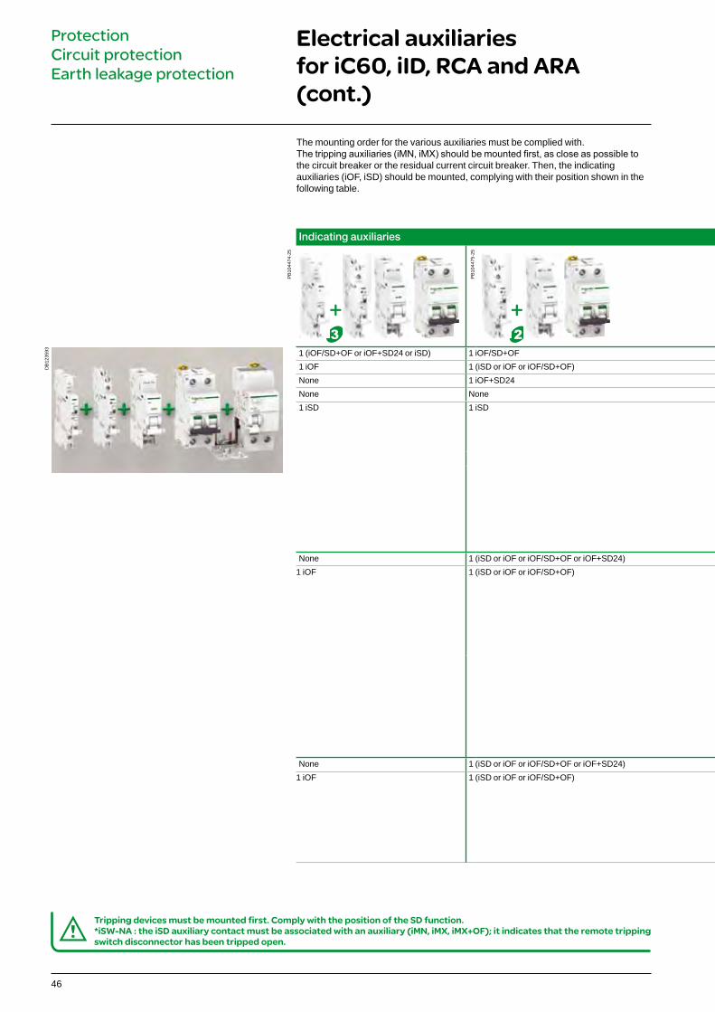
d Tripping devices must be mounted first. Comply with the position of the SD function.*iSW-NA : the iSD auxiliary contact must be associated with an auxiliary (iMN, iMX, iMX+OF); it indicates that the remote tripping switch disconnector has been tripped open.
The mounting order for the various auxiliaries must be complied with.The tripping auxiliaries (iMN, iMX) should be mounted first, as close as possible to the circuit breaker or the residual current circuit breaker. Then, the indicating auxiliaries (iOF, iSD) should be mounted, complying with their position shown in the following table.
+ +
DB
1235
93
Indicating auxiliaries Tripping auxiliaries Remote control Device Vigi iC60
PB
1044
74-2
5
PB
1044
75-2
5
PB
1044
96-2
5
ARA automatic recloser or
RCA remote control
iC60 circuit breaker or
iID residual current circuit breaker
Vigi iC60 add-on residual current device
1 (iOF/SD+OF or iOF+SD24 or iSD) 1 iOF/SD+OF 1 (iMN, iMNs, iMNx or iMX, iMX+OF or iMSU) max. –
PB
1044
37-2
5
iC60
PB
1044
66-2
5
Vigi iC60
1 iOF 1 (iSD or iOF or iOF/SD+OF) 2 (iMN, iMNs, iMNx or iMX, iMX+OF or iMSU) max.None 1 iOF+SD24 2 (iMN, iMNs, iMNx or iMX, iMX+OF or iMSU) max.None None 3 iMSU max.1 iSD 1 iSD 1 (iMN, iMNs, iMNx or iMX, iMX+OF or iMSU) max.
–
PB
1044
72-2
5
iID/iSW-NA
–
None 1 (iSD or iOF or iOF/SD+OF or iOF+SD24) 1 (iMN, iMNs, iMNx or iMX, iMX+OF or iMSU) max.
PB
1062
56-2
5
ARA
PB
1044
37-2
5
iC60
PB
1044
66-2
5
Vigi iC60
1 iOF 1 (iSD or iOF or iOF/SD+OF) None
PB
1044
72-2
5
iID
–
None 1 (iSD or iOF or iOF/SD+OF or iOF+SD24) 1 (iMX or iMN or iMSU) max.
PB
1062
53-2
5
RCA
PB
1044
37-2
5
iC60
PB
1044
37-2
5
Vigi iC60
1 iOF 1 (iSD or iOF or iOF/SD+OF) None

47
Indicating auxiliaries Tripping auxiliaries Remote control Device Vigi iC60
PB
1044
74-2
5
PB
1044
75-2
5
PB
1044
96-2
5
ARA automatic recloser or
RCA remote control
iC60 circuit breaker or
iID residual current circuit breaker
Vigi iC60 add-on residual current device
1 (iOF/SD+OF or iOF+SD24 or iSD) 1 iOF/SD+OF 1 (iMN, iMNs, iMNx or iMX, iMX+OF or iMSU) max. –
PB
1044
37-2
5
iC60
PB
1044
66-2
5
Vigi iC60
1 iOF 1 (iSD or iOF or iOF/SD+OF) 2 (iMN, iMNs, iMNx or iMX, iMX+OF or iMSU) max.None 1 iOF+SD24 2 (iMN, iMNs, iMNx or iMX, iMX+OF or iMSU) max.None None 3 iMSU max.1 iSD 1 iSD 1 (iMN, iMNs, iMNx or iMX, iMX+OF or iMSU) max.
–
PB
1044
72-2
5
iID/iSW-NA
–
None 1 (iSD or iOF or iOF/SD+OF or iOF+SD24) 1 (iMN, iMNs, iMNx or iMX, iMX+OF or iMSU) max.
PB
1062
56-2
5
ARA
PB
1044
37-2
5
iC60
PB
1044
66-2
5
Vigi iC60
1 iOF 1 (iSD or iOF or iOF/SD+OF) None
PB
1044
72-2
5
iID
–
None 1 (iSD or iOF or iOF/SD+OF or iOF+SD24) 1 (iMX or iMN or iMSU) max.
PB
1062
53-2
5
RCA
PB
1044
37-2
5
iC60
PB
1044
37-2
5
Vigi iC60
1 iOF 1 (iSD or iOF or iOF/SD+OF) None
+
48
PB
1044
77-3
5D
B11
8804
DB
1188
05
Electrical auxiliaries for iC60, iID, iDPN Vigi, iSW-NA, RCA and ARA (cont.)
ProtectionCircuit protectionEarth leakage protection
PB
1044
78-3
5
PB
1044
80-3
5
*(Ua)Voltages measured between the phase and the neutral conductor, at which the iMSU device must control the associated protective device.
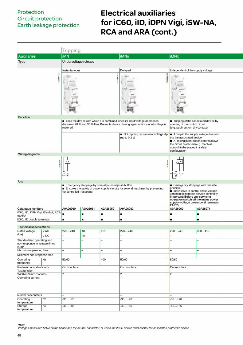
Tripping Auxiliaries iMN iMNs iMNx iMSU iMX iMX+OFType Undervoltage release Overvoltage release Shunt release
Instantaneous Delayed Independent of the supply voltage With Open/Close auxiliary contact
Function b Trips the device with which it is combined when its input voltage decreases
(between 70 % and 35 % Un). Prevents device closing again until its input voltage is restored
b Tripping of the associated device by opening of the control circuit (e.g. push-button, dry contact)
b Switches off the power supply by opening the breaker with which it is combined, in the event that the phase/neutral voltage is exceeded (loss of neutral). For a four-phase network, use three iMSU tripping auxiliaries
b Trips the breaker when powered
b Not tripping on transient voltage dip (up to 0.2 s)
b A drop in the supply voltage does not trip the associated device
b A locking push-button control allows the circuit protected (e.g. machine control) to be placed in safety configuration
b Includes an open/close contact (OF) to indicate the "open" or "closed" position of the breaker
Wiring diagrams
U <
E2 N/
L1
L2E1
U >
12 C2
11
(L/+)
C1
(N/-)
14
U >
Use b Emergency stoppage by normally closed push button b Ensures the safety of power supply circuits for several machines by preventing
"uncontrolled" restarting
b Emergency stoppage with fail-safe principle
b Insensitive to control circuit voltage variation to increase service continuityImportant: Before any servicing operation switch off the mains power supply (voltage presence at terminals E1/E2)
b Protection of equipment against overvoltages on the electrical network (neutral conductor break)
b Voltage monitoring between phase and neutral conductors
b Emergency stoppage by normally open push button
b Emergency stoppage by normally open push button
b Remote indication of the position of the associated breaker
Catalogue numbers A9A26960 A9A26961 A9A26959 A9A26963 A9A26969 A9A26971 A9A26500 A9A26476 A9A26477 A9A26478 A9A26946 A9A26947 A9A26948iC60, iID, iDPN Vigi, iSW-NA, RCA et ARA b b b b b b b b b b b b b
iC60, iID double terminals b b b b b b b b b b b b b
Technical specifications Rated voltage (Ue)
V AC 220…240 48 115 220…240 220…240 380…415 230 100…415 48 12…24 100…415 48 12…24V DC – 48 – – – 110…130 48 12…24 110…130 48 12…24
Standardised operating and non-response to voltage times (Ua)*
– – – – – – 255 V AC 275 V AC 300 V AC 350 V AC 400 V AC – – – – – –
Maximum operating time – – – – – – No tripping 15 s 5 s 0.75 s 0.20 s – – – – – –Minimum non-response time – – – – – – 3 s 1 s 0.25 s 0.07 s – – – – – –Operating frequency
Hz 50/60 400 50/60 50/60 50/60 50/60 50/60
Red mechanical indicator On front face On front face On front face On front face On front face On front faceTest function – – – – – –Width in 9 mm modules 2 2 2 2 2 2Operating current – – – – – y 24 V DC 10 mA mini, 6 A maxi
48 V DC 2 Ay 130 V DC 1 Ay 240 V AC 6 A415 V AC 3 A
Number of contacts – – – – – 1 NO/NCOperating temperature
°C -35…+70 -35…+70 -35…+70 -35…+70 -35…+70 -35…+70
Storage temperature
°C -40…+85 -40…+85 -40…+85 -40…+85 -40…+85 -40…+85

49
Tripping Auxiliaries iMN iMNs iMNx iMSU iMX iMX+OFType Undervoltage release Overvoltage release Shunt release
Instantaneous Delayed Independent of the supply voltage With Open/Close auxiliary contact
Function b Trips the device with which it is combined when its input voltage decreases
(between 70 % and 35 % Un). Prevents device closing again until its input voltage is restored
b Tripping of the associated device by opening of the control circuit (e.g. push-button, dry contact)
b Switches off the power supply by opening the breaker with which it is combined, in the event that the phase/neutral voltage is exceeded (loss of neutral). For a four-phase network, use three iMSU tripping auxiliaries
b Trips the breaker when powered
b Not tripping on transient voltage dip (up to 0.2 s)
b A drop in the supply voltage does not trip the associated device
b A locking push-button control allows the circuit protected (e.g. machine control) to be placed in safety configuration
b Includes an open/close contact (OF) to indicate the "open" or "closed" position of the breaker
Wiring diagrams
U <
E2 N/
L1
L2E1
U >
12 C2
11
(L/+)
C1
(N/-)
14
U >
Use b Emergency stoppage by normally closed push button b Ensures the safety of power supply circuits for several machines by preventing
"uncontrolled" restarting
b Emergency stoppage with fail-safe principle
b Insensitive to control circuit voltage variation to increase service continuityImportant: Before any servicing operation switch off the mains power supply (voltage presence at terminals E1/E2)
b Protection of equipment against overvoltages on the electrical network (neutral conductor break)
b Voltage monitoring between phase and neutral conductors
b Emergency stoppage by normally open push button
b Emergency stoppage by normally open push button
b Remote indication of the position of the associated breaker
Catalogue numbers A9A26960 A9A26961 A9A26959 A9A26963 A9A26969 A9A26971 A9A26500 A9A26476 A9A26477 A9A26478 A9A26946 A9A26947 A9A26948iC60, iID, iDPN Vigi, iSW-NA, RCA et ARA b b b b b b b b b b b b b
iC60, iID double terminals b b b b b b b b b b b b b
Technical specifications Rated voltage (Ue)
V AC 220…240 48 115 220…240 220…240 380…415 230 100…415 48 12…24 100…415 48 12…24V DC – 48 – – – 110…130 48 12…24 110…130 48 12…24
Standardised operating and non-response to voltage times (Ua)*
– – – – – – 255 V AC 275 V AC 300 V AC 350 V AC 400 V AC – – – – – –
Maximum operating time – – – – – – No tripping 15 s 5 s 0.75 s 0.20 s – – – – – –Minimum non-response time – – – – – – 3 s 1 s 0.25 s 0.07 s – – – – – –Operating frequency
Hz 50/60 400 50/60 50/60 50/60 50/60 50/60
Red mechanical indicator On front face On front face On front face On front face On front face On front faceTest function – – – – – –Width in 9 mm modules 2 2 2 2 2 2Operating current – – – – – y 24 V DC 10 mA mini, 6 A maxi
48 V DC 2 Ay 130 V DC 1 Ay 240 V AC 6 A415 V AC 3 A
Number of contacts – – – – – 1 NO/NCOperating temperature
°C -35…+70 -35…+70 -35…+70 -35…+70 -35…+70 -35…+70
Storage temperature
°C -40…+85 -40…+85 -40…+85 -40…+85 -40…+85 -40…+85
DB
1230
12
DB
1188
08
Electrical auxiliaries for iC60, iID, iDPN Vigi, iSW-NA, RCA and ARA (cont.)
ProtectionCircuit protectionEarth leakage protection
PB
1044
96-3
5
PB
1044
81-3
5
DB
1188
06P
B10
4479
-35

50
IndicationAuxiliaries iOF iSD iOF/SD+OF iOF+SD24Type Open/close
auxiliary contactFault indicating contact Double open/close or fault
indicating contactDouble open/close and fault indicating contact
Function b Changeover contact
indicates "open" or "closed" position of the breaker
b Changeover contact indicates position of the breaker; upon:
v electrical fault v action on tripping auxiliary b Same indication as
VISI-TRIP
b The iOF/SD+OF auxiliary is a 2-in-1 product: via a mechanical selector switch, it provides two contacts, OF+SD or OF+OF
b 2 contacts (1 NO + 1 NC) can report the signalling information of the associated device to the Acti 9 Smartlink or a programmable logic controller:
v electrical fault v actuation of the tripping
auxiliary v "Open" or "Closed"
position of the associated device
Wiring diagrams
OF position SD positionUse
b Remote indication of the position of the associated breaker
b Remote indication of tripping upon a fault of the associated breaker
b Remote indication of position and/or tripping upon a fault of the associated breaker
b Remote indication of position and tripping upon a fault of the associated breaker
Catalogue numbers A9A26924 A9A26869 A9A26927 A9A26855 A9A26929 A9A26897iC60, iID, iDPN Vigi, iSW-NA, RCA et ARA b – b – b b
iC60, iID double terminals – b – b b b
Technical specifications Rated voltage (Ue) V AC 240…415 240…415 240…415 -
V DC 24…130 24…130 24…130 24Operating frequency
Hz 50/60 50/60 50/60 -
Red mechanical indicator – On front face On front face On front faceTest function On toggle On toggle On toggle On toggleWidth in 9 mm modules 1 1 1 1Operating current 24 V DC 10 mA mini, 6 A maxi 2 mA mini, 50 mA maxi
48 V DC 2 A -60 V DC 1.5 A -130 V DC 1 A -240 V AC 6 A -415 V AC 3 A -
Number of contacts 1 NO/NC 1 NO/NC 1 NO/NC + 1 NO/NC 1 NO/NCOperating temperature
°C -35…+70 -35…+70 -35…+70 -25…+70
Storage temperature
°C -40…+85 -40…+85 -40…+85 -40…+85
DB
1188
11
DB
1188
12
DB
1188
10
DB
1188
13
DB
1243
18
PB
1044
74-3
5
PB
1044
76-3
5
PB
1044
75-3
5
PB
1077
50-3
5
Electrical auxiliaries for iC60, iID, iDPN Vigi, iSW-NA, RCA and ARA (cont.)
ProtectionCircuit protectionEarth leakage protection
51
Electrical auxiliaries for iC60, iID, iDPN Vigi, iSW-NA, RCA and ARA (cont.)
ProtectionCircuit protectionEarth leakage protection
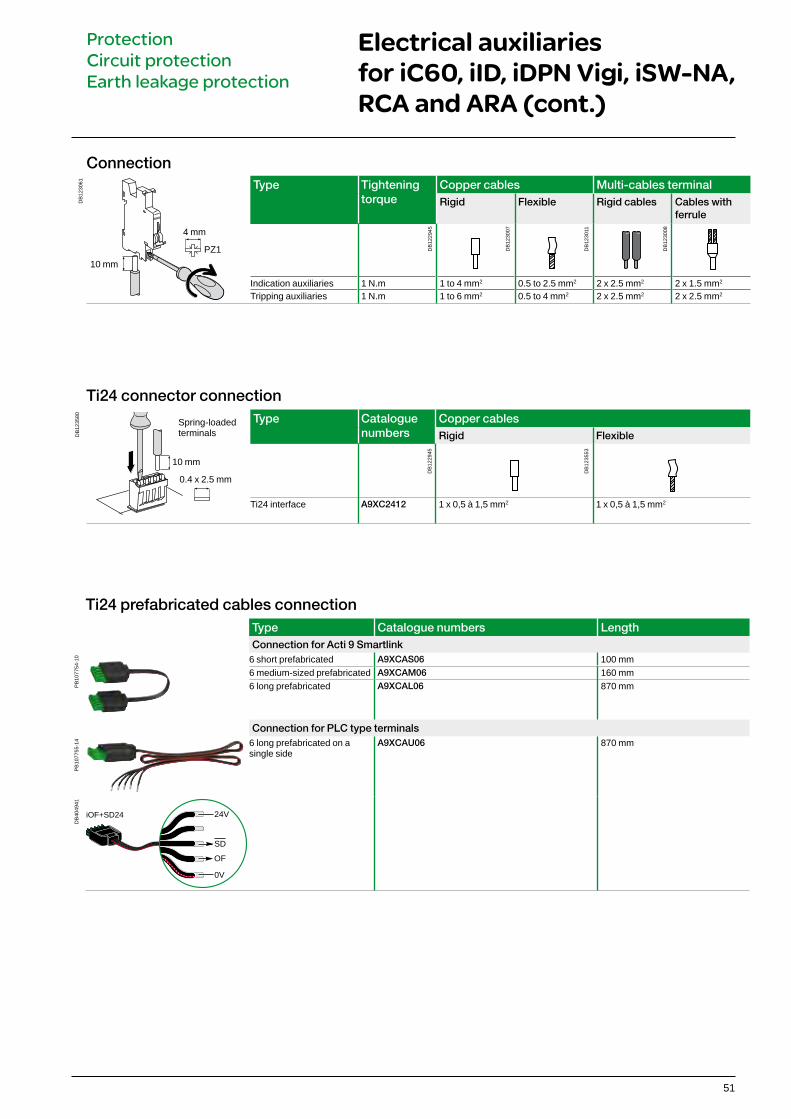
Connection
DB
1230
61
4 mm
10 mmPZ1
Type Tightening torque
Copper cables Multi-cables terminalRigid Flexible Rigid cables Cables with
ferrule
Indication auxiliaries 1 N.m 1 to 4 mm2 0.5 to 2.5 mm2 2 x 2.5 mm2 2 x 1.5 mm2
Tripping auxiliaries 1 N.m 1 to 6 mm2 0.5 to 4 mm2 2 x 2.5 mm2 2 x 2.5 mm2
DB
1229
45
DB
1230
07
DB
1230
11
DB
1230
08
Ti24 connector connection
DB
1235
80 Type Catalogue numbers
Copper cablesRigid Flexible
Ti24 interface A9XC2412 1 x 0,5 à 1,5 mm2 1 x 0,5 à 1,5 mm2
DB
1229
45
DB
1235
53
Spring-loadedterminals
10 mm
0.4 x 2.5 mm
Ti24 prefabricated cables connectionType Catalogue numbers LengthConnection for Acti 9 Smartlink
PB
1077
54-1
0 6 short prefabricated A9XCAS06 100 mm6 medium-sized prefabricated A9XCAM06 160 mm6 long prefabricated A9XCAL06 870 mm
Connection for PLC type terminals
PB
1077
55-1
4 6 long prefabricated on a single side
A9XCAU06 870 mm
DB
4049
41
24V
SD
OF
0V
iOF+SD24

52
Mounting Accessories Rotary handle Plug-in base Padlocking device
Function Front or side-mounted control
b Degree of protection: IP55 rotary handle b Installation: v the control mechanism is mounted on the device v the rotary handle is fixed to the front or side of the
enclosure b Front-mounted (on door or faceplate) b Prevents the door from opening when the device is
in the ON position (can be deactivated) b Can be padlocked when the device is in the "open"
position (can be padlocked with the device in the "closed" position subject to adaptation)
b Can be locked by padlock of (dia. 5 to 8 mm), not supplied with the device
b Pushbutton: iID test available in the front face of the rotary handle
b The Laser Square tool brings the accurency to align the circuit breaker and the rotary handle
Allows a breaker to be removed or replaced quickly, without handling the connections
b Degree of protection: IP20 b Consists of: v a base to be fastened on a rail (or panel) v 2 "blades" to be fastened in the device's
terminals b Connection: tunnel terminals for cable up to
35 mm2 rigid, 25 mm2 flexible, b Installation: v in universal enclosure v on horizontal rail b Height: 178 mm b Not compatible with Vigi iC60 and auxiliaries b Can be locked by padlock of (dia. 6 mm), not
supplied with the device
Used to padlock breaker in open or closed position b Padlock diameter: 3 to 6 mm b Sealable (max. diameter: 1.2 mm) b Locking in ON position does not prevent tripping of the breaker in the event of
faults b Suitable for IEC/EN 60947-2 compliant disconnection
Catalogue numbers
A9A27005 A9A27006 A9A27008 GVAPL01 A9A27003(1 per pole)
MCB RCBOOperating sub-assembly+ + A9A26970 A9A27049
Black handle Red handle No handleSet of 1 1 1 1 1 10 10
SuitabilityiC60 b 2P, 3P, 4P b b iSW b 2P, 3P, 4P b b iC60 + Vigi iC60 b 2P, 3P, 4P – b iID b b y 63 A b Reflex iC60 or RCA+iC60 or ARA+iC60
– – b
ARA+iID – – b
Accessories for iC60, iID , iDPN Vigi, iSW-NA, Reflex iC60, RCA, ARA, iSW
ProtectionCircuit protectionEarth leakage protection
PB
1045
09-3
5
PB
1045
08-3
5
PB
1062
97_1
0

53
Mounting Accessories Rotary handle Plug-in base Padlocking device
Function Front or side-mounted control
b Degree of protection: IP55 rotary handle b Installation: v the control mechanism is mounted on the device v the rotary handle is fixed to the front or side of the
enclosure b Front-mounted (on door or faceplate) b Prevents the door from opening when the device is
in the ON position (can be deactivated) b Can be padlocked when the device is in the "open"
position (can be padlocked with the device in the "closed" position subject to adaptation)
b Can be locked by padlock of (dia. 5 to 8 mm), not supplied with the device
b Pushbutton: iID test available in the front face of the rotary handle
b The Laser Square tool brings the accurency to align the circuit breaker and the rotary handle
Allows a breaker to be removed or replaced quickly, without handling the connections
b Degree of protection: IP20 b Consists of: v a base to be fastened on a rail (or panel) v 2 "blades" to be fastened in the device's
terminals b Connection: tunnel terminals for cable up to
35 mm2 rigid, 25 mm2 flexible, b Installation: v in universal enclosure v on horizontal rail b Height: 178 mm b Not compatible with Vigi iC60 and auxiliaries b Can be locked by padlock of (dia. 6 mm), not
supplied with the device
Used to padlock breaker in open or closed position b Padlock diameter: 3 to 6 mm b Sealable (max. diameter: 1.2 mm) b Locking in ON position does not prevent tripping of the breaker in the event of
faults b Suitable for IEC/EN 60947-2 compliant disconnection
Catalogue numbers
A9A27005 A9A27006 A9A27008 GVAPL01 A9A27003(1 per pole)
MCB RCBOOperating sub-assembly+ + A9A26970 A9A27049
Black handle Red handle No handleSet of 1 1 1 1 1 10 10
SuitabilityiC60 b 2P, 3P, 4P b b iSW b 2P, 3P, 4P b b iC60 + Vigi iC60 b 2P, 3P, 4P – b iID b b y 63 A b Reflex iC60 or RCA+iC60 or ARA+iC60
– – b
ARA+iID – – b
Accessories for iC60, iID , iDPN Vigi, iSW-NA, Reflex iC60, RCA, ARA, iSW (cont.)
ProtectionCircuit protectionEarth leakage protection
PB
1044
92-1
5
P13
5159
-40
DB
1235
99

54
Accessories for iC60, iID , iDPN Vigi, iSW-NA, Reflex iC60, RCA, ARA, iSW (cont.)
ProtectionCircuit protectionEarth leakage protection
Security Accessories Screw shield Terminal shield Inter-pole barrier Spacer
FunctionPrevents any contact with the connecting screws
b Upgrades degree of protection to IP20D b Sealable, max. diameter 1.2 mm
Prevents any contact with the terminals b Upgrades degree of protection
to IP20D b Sealable, max. diameter 1.2 mm b Set of two, for upstream and
downstream terminals b For 3 poles: A9A26975 + A9A26976 b For 4 poles: 2 X A9A26976
Enhances insulation between connections: cables, terminals, lugs, etc
b Used to: v complete rows v separate devices.
Width: 1 x 9 mm module b Allows cable routing
from one row to another, (above and below), up to 6 mm2
Catalogue numbers
A9A26982 A9A26981 A9A26975 A9A26976 A9A27001 A9A27062
Set of 12 x 1 pole 20 x 4 poles (splittable) 2 x 1 pole 2 x 2 poles 10 5
SuitabilityiC60 – b b b b b iSW – – b b b b Vigi iC60 b – – – – b iID – b – b b b Reflex iC60 or RCA+iC60 or ARA+iC60
– b b b b b
ARA+iID – b – b b b
PB
1044
89-1
4
PB
1045
02-3
5
PB
1045
03-3
5
PB
1044
84-3
0
PB
1044
83-3
5
PB
1044
88-1
4

DB
1187
80
DB
1187
81
DB
1187
83
DB
1187
87
DB
1229
35
DB
1187
89
DB
1187
85
55
ConnectionAccessories Multi-cable terminal 50 mm² terminal Al Screw-on connection for
ring terminal
Function For 3 copper cables:
b Rigid up to 16 mm2 b Flexible up to 10 mm2
For aluminium cables from 16 to 50 mm2
For lug tipped cables, front or rear mounting
5 mm
Catalogue numbers
19091 19096 27060 27053
Set of 4 3 1 8iC60 y 25 AReflex iC60 y 25 A
– – – b
iC60 >25 AReflex iC60 40 A, iSW
b b b b
Vigi iC60 – – – – iID b b b b iDPN Vigi – – – b iSW-NA b b b b
Tightening torque 2 N.m 10 N.m 2 N.mLenght stripping 11 mm 13 mm –Tools to use Dia. 5 mm or PZ2 Hc 1/5" or 5 mm Dia. 5mm
Marking Accessories Marker strip
Used for connection identificationCatalogue numbers
0: AB1-R0
1: AB1-R1
2: AB1-R2
3: AB1-R3
4: AB1-R4
5: AB1-R5
6: AB1-R6
7: AB1-R7
8: AB1-R8
9: AB1-R9
A: AB1-GA
B: AB1-GB
C: AB1-GC
D: AB1-GD
E: AB1-GE
F: AB1-GF
G: AB1-GG
H: AB1-GH
I: AB1-GI
J: AB1-GJ
K: AB1-GK
L: AB1-GL
M: AB1-GM
N: AB1-GN
O: AB1-GO
P: AB1-GP
Q: AB1-GQ
R: AB1-GR
S: AB1-GS
T: AB1-GT
U: AB1-GU
V: AB1-GV
W: AB1-GW
X: AB1-GX
Y: AB1-GY
Z: AB1-GZ
+: AB1-R12
-: AB1-R13
blank: AB1-RV
Set of 250
iC60, Reflex iC60, iSW
b 4 markers max. per pole
Vigi iC60 b 4 markers max. per deviceiID b 4 markers max. per deviceiDPN Vigi b 4 markers max. per deviceiSW-NA b 4 markers max. per device
Accessories for iC60, iID , iDPN Vigi, iSW-NA, Reflex iC60, RCA, ARA, iSW (cont.)
ProtectionCircuit protectionEarth leakage protection

56
iID residual current circuit breakers (AC type)
IEC/EN 61008-1
PB
1044
72-4
0
PB
1044
73-4
0
Catalogue numbersiID residual current circuit breakersType AC Width in 9 mm
moduleProduct iIDAuxiliaries
2P Sensitivity 10 mA 30 mA 100 mA 300 mA 500 mA 300 mA s 500 mA s
DB
1224
76 Rating 16 A A9R10216 - - - - - - 425 A A9R10225 A9R41225 - A9R44225 A9R16225 - -40 A - A9R41240 A9R12240 A9R44240 A9R16240 - -
63 A - A9R41263 A9R12263 A9R44263 A9R16263 A9R15263 -80 A - A9R11280 A9R12280 A9R14280 - A9R15280 -100 A - A9R11291 A9R12291 A9R14291 - A9R15291 -
4P Sensitivity 10 mA 30 mA 100 mA 300 mA 500 mA 300 mA s 500 mA s
DB
1224
77 Rating 25 A - A9R41425 - A9R44425 A9R16425 - - 840 A - A9R41440 A9R12440 A9R44440 A9R16440 A9R15440 A9R1744063 A - A9R41463 A9R12463 A9R44463 A9R16463 A9R15463 A9R1746380 A - A9R11480 A9R12480 A9R14480 A9R16480 A9R15480 A9R17480100 A - A9R11491 A9R12491 A9R14491 - A9R15491 -
Voltage rating (Ue) 2P 230 - 240 V4P 400 - 415 V
Operating frequency 50/60 Hz
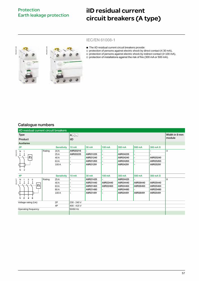
b The iID residual current circuit breakers provide: v protection of persons against electric shock by direct contact (y 30 mA), v protection of persons against electric shock by indirect contact (u 100 mA), v protection of installations against the risk of fire (300 mA or 500 mA).
Protection Earth leakage protection
57
Catalogue numbersiID residual current circuit breakersType A Width in 9 mm
moduleProduct iIDAuxiliaries
2P Sensitivity 10 mA 30 mA 100 mA 300 mA 500 mA 300 mA s
DB
1224
76 Rating 16 A A9R20216 - - - - - 425 A A9R20225 A9R21225 - A9R24225 - -40 A - A9R21240 - A9R24240 - A9R25240
63 A - A9R21263 - A9R24263 - A9R25263100 A - A9R21291 - A9R24291 - A9R25291
4P Sensitivity 10 mA 30 mA 100 mA 300 mA 500 mA 300 mA s
DB
1224
77 Rating 25 A - A9R21425 - A9R24425 - - 840 A - A9R21440 A9R22440 A9R24440 A9R26440 A9R2544063 A - A9R21463 A9R22463 A9R24463 A9R26463 A9R2546380 A - A9R21480 - A9R24480 - A9R25480100 A - A9R21491 - A9R24491 A9R26491 A9R25491
Voltage rating (Ue) 2P 230 - 240 V4P 400 - 415 V
Operating frequency 50/60 Hz
PB
1044
72-4
0
IEC/EN 61008-1P
B10
4473
-40
iID residual current circuit breakers (A type)
b The iID residual current circuit breakers provide: v protection of persons against electric shock by direct contact (y 30 mA), v protection of persons against electric shock by indirect contact (u 100 mA), v protection of installations against the risk of fire (300 mA or 500 mA).
Protection Earth leakage protection
58
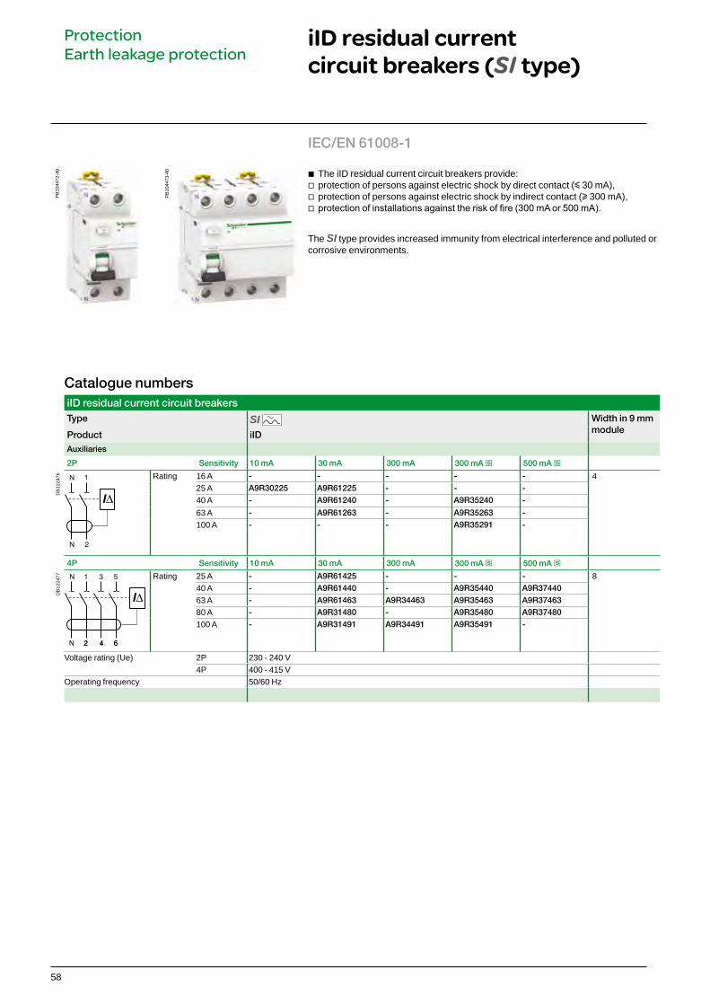
iID residual current circuit breakers (SI type)
Catalogue numbersiID residual current circuit breakersType SI Width in 9 mm
moduleProduct iIDAuxiliaries
2P Sensitivity 10 mA 30 mA 300 mA 300 mA s 500 mA s
DB
1224
76 Rating 16 A - - - - - 425 A A9R30225 A9R61225 - - -40 A - A9R61240 - A9R35240 -
63 A - A9R61263 - A9R35263 -100 A - - - A9R35291 -
4P Sensitivity 10 mA 30 mA 300 mA 300 mA s 500 mA s
DB
1224
77 Rating 25 A - A9R61425 - - - 840 A - A9R61440 - A9R35440 A9R3744063 A - A9R61463 A9R34463 A9R35463 A9R3746380 A - A9R31480 - A9R35480 A9R37480100 A - A9R31491 A9R34491 A9R35491 -
Voltage rating (Ue) 2P 230 - 240 V4P 400 - 415 V
Operating frequency 50/60 Hz
b The iID residual current circuit breakers provide: v protection of persons against electric shock by direct contact (y 30 mA), v protection of persons against electric shock by indirect contact (u 300 mA), v protection of installations against the risk of fire (300 mA or 500 mA).
The SI type provides increased immunity from electrical interference and polluted or corrosive environments.
PB
1044
72-4
0
IEC/EN 61008-1P
B10
4473
-40
Protection Earth leakage protection

59
Visi-trip window b Fault tripping is indicated by a red
mechanical indicator on the front face
PB
1044
72-4
0
b Double clip for dismounting with comb busbar in place
b Insulated terminals IP20
b Test button
SI typeThe SI type provides increased immunity from electrical interference and polluted or corrosive environments.
Positive contact indication b Suitable for industrial isolation according to
IEC/EN 60947-3 standard b The presence of the green strip guarantees
physical opening of the contacts and allows operations to be performed on the downstream circuit in complete safety
Protection Earth leakage protection
iID residual current circuit breakers (AC, A, SI types) (cont.)
PB
1045
48-4
0
b Large circuit labelling area

60
Technical dataMain characteristics
Insulation voltage (Ui) 500 VPollution degree 3Rated impulse withstand voltage (Uimp) 6 kVAccording to IEC/EN 61008-1
Making and breaking capacity (Im/IDm) 1500 ASurge current withstand (8/20 μs) without tripping
AC and A types (no selective s) 250 ÂAC, A types (selective s) 3 kÂ
SI type 3 kÂConditional rated short circuit current (Inc/IDc)
With iC60N/H/L Equal to breaking capacity of iC60With fuse 10,000 A
Additional characteristics Degree of protection Device only IP20
Device in modular enclosure IP40Insulation classe II
Endurance (O-C) Electrical (AC1) 16 to 63 A 15,000 cycles80 to 100 A 10,000 cycles
Mechanical 20,000 cyclesOperating temperature
AC type -5°C to +60°C
A and SI types -25°C to +60°CStorage temperature -40°C to +85°C
iID residual current circuit breakers (AC, A, SI types)
Connection Without accessory With accessories*
DB
1229
47 Type Tightening torque
Copper cables 50 mm² Al terminal
Screw-on connection for ring terminal
Multi-cables terminalRigid Flexible
or ferruleRigid cables
Flexible cables
iID 3.5 N.m 1 to 35 mm2 1 to 25 mm2 50 mm2 Ø 5 mm 3 x 16 mm2 3 x 10 mm2D
B12
2945
DB
1229
46
PZ2
14 mm
DB
1229
35
DB
1187
89
DB
1187
87
Protection Earth leakage protection
6.5 mm
DB
1233
10D
B12
3312
Clip on DIN rail 35 mm.
Indifferent position of installation.
DB
1233
14 IP20 IP40

62
Principle of catalogue numbersProtectionCircuit protectionEarth leakage protection
iID, iC60, Vigi iC60, Reflex iC60, switches
Range Family Code Internal code Poles Code Rating (A) CodeActi 9 (A9) iID R 0 0 0 00
Vigi iC60 V 1P 1 0.5 70iC60 F 2P 2 0.75 71
Auxiliaries and accessories A 3P 3 1 01
Switches S 4P 4 1.6 72
Reflex iC60 C 1N 5 2 02
1P+N 6 2.5 73
3P+N 7 3 03
4 04
6 06
6.3 76
8 08
10 10
12.5 82
13 13
16 16
20 20
25 25
32 32
40 40
50 50
63 6380 80
100 91
125 92
A9 R 15 2 63
Comb busbar and comb busbar accessories
Range Family Code Type Type of installation
Number of poles Dimensioning
Acti 9 (A9) Comb busbar
X Comb busbar 1P 1 Comb busbar Number of 18 mm modules(approximately)Fork teeth F Horizontal H
Pin teeth P 2P 2 Accessories Number of pieces per cat. no.
Auxiliarisable A 3P 3Accessories 4P 4End-piece E Double terminals D 4P balanced, with neutral 5Tooth cover T Single terminal M 3P balanced for single-poles 6Connector C
A9 X P H 4 12