magnetorheological damping for spring frogs abstract the goal of this study was to determine if a...
TRANSCRIPT
High-Speed Rail IDEA Program
Magnetorheological Damping for Spring Frogs Final Report for High-Speed Rail IDEA Project 46 Prepared by: Leslie E. Olson Texas Transportation Institute Texas A&M University System College Station, TX July 2007

ii
INNOVATIONS DESERVING EXPLORATORY ANALYSIS (IDEA) PROGRAMS MANAGED BY THE TRANSPORTATION RESEARCH BOARD This investigation was performed as part of the High-Speed Rail IDEA program supports innovative methods and technology in support of the Federal Railroad Administration’s (FRA) next-generation high-speed rail technology development program. The High-Speed Rail IDEA program is one of four IDEA programs managed by TRB. The other IDEA programs are listed below. • NCHRP Highway IDEA focuses on advances in the design, construction, safety, and
maintenance of highway systems, is part of the National Cooperative Highway Research Program.
• Transit IDEA focuses on development and testing of innovative concepts and methods for improving transit practice. The Transit IDEA Program is part of the Transit Cooperative Research Program, a cooperative effort of the Federal Transit Administration (FTA), the Transportation Research Board (TRB) and the Transit Development Corporation, a nonprofit educational and research organization of the American Public Transportation Association. The program is funded by the FTA and is managed by TRB.
• Safety IDEA focuses on innovative approaches to improving motor carrier, railroad, and highway safety. The program is supported by the Federal Motor Carrier Safety Administration and the FRA.
Management of the four IDEA programs is integrated to promote the development and testing of nontraditional and innovative concepts, methods, and technologies for surface transportation. For information on the IDEA programs, contact the IDEA programs office by telephone (202-334-3310); by fax (202-334-3471); or on the Internet at http://www.trb.org/idea IDEA Programs Transportation Research Board 500 Fifth Street, NW Washington, DC 20001
The project that is the subject of this contractor-authored report was a part of the Innovations Deserving Exploratory Analysis (IDEA) Programs, which are managed by the Transportation Research Board (TRB) with the approval of the Governing Board of the National Research Council. The members of the oversight committee that monitored the project and reviewed the report were chosen for their special competencies and with regard for appropriate balance. The views expressed in this report are those of the contractor who conducted the investigation documented in this report and do not necessarily reflect those of the Transportation Research Board, the National Research Council, or the sponsors of the IDEA Programs. This document has not been edited by TRB. The Transportation Research Board of the National Academies, the National Research Council, and the organizations that sponsor the IDEA Programs do not endorse products or manufacturers. Trade or manufacturers' names appear herein solely because they are considered essential to the object of the investigation.
iii
MAGNETORHEOLOGICAL DAMPING FOR SPRING FROGS
IDEA PROGRAM FINAL REPORT
FOR THE PERIOD JULY 2005 THROUGH DECEMBER 2006 HSR-46
PREPARED FOR THE IDEA PROGRAM
TRANSPORTATION RESEARCH BOARD NATIONAL RESEARCH COUNCIL
LESLIE E. OLSON TEXAS TRANSPORTATION INSTITUTE
TEXAS A&M UNIVERSITY SYSTEM COLLEGE STATION, TEXAS 77843-3135
JULY 2007
iv
ACKNOWLEDGEMENTS
The research reported herein was performed under the Transportation Research Board’s High-Speed Rail IDEA Program, contract HSR-46, by the Rail Research Center of the Texas Transportation Institute at Texas A&M University. Texas Transportation Institute was the contractor for this research. Leslie Olson, Associate Research Scientist, and Paul Roschke, Associate Research Engineer, Texas Transportation Institute were joint investigators.
The authors express their sincere thanks to Mr. Charles Taylor, IDEA Project Manager, for his support and guidance throughout the project; to Mr. Ed Kohake of Union Pacific Railroad without whose support the field tests could not have taken place; and to Mr. Trea Miller of the Union Pacific Railroad whose local scheduling allowed the field work to take place.
The work was done under the general supervision of Dr. Paul N. Roschke. The laboratory investigation work was done at Texas A&M University under the supervision of Professor Roschke and Leslie Olson.
v
ABSTRACT The goal of this study was to determine if a magnetorheological (MR) damper can replace the
hydraulic retarder in spring frogs used on railways in the United States. Hydraulic retarders slow the return of the spring rail to reduce the slamming back of the spring rail that would otherwise occur. An MR damper is similar to a hydraulic damper except it uses a special MR fluid whose viscosity can be controlled by controlling electric current through electromagnetic coils wrapped around the piston head. This report discusses findings from a literature review; data acquisition of field data from a spring frog (SF); design, manufacture, and operation of a two-stage MR damper; a nonparametric model for operation of a spring frog; and a SF motion control algorithm. Field data from operation of a spring frog were collected during passage of three trains in Navasota, Texas. Several transducers, including an LVDT (Linear Variable Displacement Transducer), an accelerometer, and a load pin were used to collect real-time dynamic performance data in the field from a SF that has (1) no passive retarder and (2) a conventional passive retarder. Data were analyzed both in the frequency and time domains. An MR damper was designed to replace a passive hydraulic retarder that is currently in use. The process of design, fabrication, and assembly of a new MR damper is described. Performance tests were conducted on the prototype MR damper in a uniaxial MTS testing machine. Force levels that result from applied displacement, velocity, and voltage signals to the damper are presented. A MR damper fuzzy model was developed to represent characteristics of the behavior of the MR damper using an Adaptive Neuro-Fuzzy Inference System (ANFIS). Finally, a control algorithm for the SF motion control in real time was also developed and experimental results are reported.
Union Pacific Railroad management worked with the research team to conduct field tests on the
prototype MR damper in a spring frog. The MR damper was installed and allowed to operate in a completely passive condition for a period of six weeks. The MR damper was capable of holding the spring rail in the open position against the spring loading for periods of 200 seconds or more. The research team then instrumented the MR damper and applied power to the cylinder coil as a train transitioned through the switch. The MR cylinder shaft failed immediately. Subsequent analysis determined that the cylinder shaft failed due to bending fatigue caused by off-center loading that was due to the method used to adapt the MR cylinder to the retarder mounting brackets as designed by the manufacturer of the switch. Results of this project led to the conclusions that MR dampers hold the potential for a viable alternative to conventional hydraulic retarders that would be more durable and more effective. Further development of this concept should include the redesign of the mounting brackets to avoid off-center loading of the MR cylinder, followed by comprehensive laboratory and field testing.
KEYWORDS
Magnetorheological Damper MR damper Magnetorheologic Magnetorheological Retarder Spring Frog Spring Fail Frog Switch Point
CONVERSION FACTORS KiloNewton = 224.80894 pound force KiloNewton-meters = 737.56215 foot-pounds force
vi
TABLE OF CONTENTS
Page ACKNOWLEDGEMENTS ................................................................................. ii ABSTRACT and KEYWORDS ......................................................................... iii TABLE OF CONTENTS .................................................................................... iv EXECUTIVE SUMMARY ................................................................................ vii CHAPTER 1-INTRODUCTION......................................................................... 1 CHAPTER 2-DATA ACQUISITION AND ANALYSIS .................................. 5 DATA ACQUISITION WITH RETARDER IN PLACE ...................................... 7 TIME DOMAIN ANALYSIS................................................................................. 8 FREQUENCY DOMAIN ANALYSIS ................................................................ 10 CHAPTER 3-MAGNETORHEOLOGICAL DAMPER ................................ 12 DESIGN ................................................................................................................ 12 FABRICATION.................................................................................................... 13 PERFORMANCE TESTS .................................................................................... 16 TESTING INPUT SIGNAL GENERATION....................................................... 16 DATA ACQUISITION......................................................................................... 16 TEST RESULTS................................................................................................... 18 CHAPTER 4-CONTROLLER DESIGN.......................................................... 19 CONTROL ALGORITHM................................................................................... 19 CONTROLLER LABORATORY TESTING ...................................................... 21 CHAPTER 5-FIELD TESTING.........................................................................23
CHAPTER 6-CONCLUSIONS AND RECOMMENDATIONS.................... 28 REFERENCES.................................................................................................... 30
APPENDIX A.......................................................................................................33 APPENDIX B .......................................................................................................34

vii
LIST OF FIGURES FIGURE 1 Traditional open-throat-frog switch. ............................................................................................ 1 FIGURE 2 Typical spring frog....................................................................................................................... 2 FIGURE 3 Research overview ....................................................................................................................... 5 FIGURE 4 Retarder mounting brackets near spring rail. ............................................................................... 6 FIGURE 5 LVDT and accelerometer transducer attached to the spring rail. ................................................. 7 FIGURE 6 A passive retarder in the Navasota SF with data acquisition transducers ................................... 7 FIGURE 7 Comparison of retarder equipped and non-equipped SF spring rail displacement. ..................... 8 FIGURE 8 Time history of displacement, velocity, and acceleration from Train 1 ....................................... 9 FIGURE 9 Short segment of data from passage of train 3. .......................................................................... 10 FIGURE 10 FFT-Based frequency displacement response (Train 3).......................................................... 11 FIGURE 11 FFT-Based frequency acceleration response (Train 3)............................................................. 11 FIGURE 12 Side view of the designed MR Damper.................................................................................... 13 FIGURE 13 Piston head with a drilled hole ................................................................................................. 14 FIGURE 14 Custom designed plug .............................................................................................................. 14 FIGURE 15 Wire wound on stages of piston ............................................................................................... 15 FIGURE 16 Pouring MR fluid ..................................................................................................................... 15 FIGURE 17 Assembled MR Damper ........................................................................................................... 15 FIGURE 18 MR Damper "passive on" load strength diagram ..................................................................... 16 FIGURE 19 MR Damper installation in a MTS machine............................................................................. 17 FIGURE 20 Schematic sketch of the MR Damper testing setup.................................................................. 18 FIGURE 21 Force and displacement relationship ....................................................................................... 19 FIGURE 22 Schematic diagram of SF control software .............................................................................. 20 FIGURE 23 Simulink diagram for control of SF motion ............................................................................. 20 FIGURE 24 Displacement and associated control voltage........................................................................... 21 FIGURE 25 MTS machine in force control mode........................................................................................ 22 FIGURE 26 MTS machine in displacement control mode........................................................................... 22 FIGURE 27 MR Damper with make-shift retainers ..................................................................................... 23 FIGURE 28 Extended adapter brackets and robust LVDT mount ............................................................... 24 FIGURE 29 MR Damper to switch fixed point adapter bracket and bolt..................................................... 25 FIGURE 30 MR Damper active field test at Tatsie, Texas, crossover switch.............................................. 25 FIGURE 31 Data collection and MR Damper control equipment................................................................ 26 FIGURE 32 MR Damper in Tatsie, Texas, SF switch after shaft failure. .................................................... 26 FIGURE 33 MR Damper piston shaft fatigue fracture................................................................................. 27 FIGURE 34 Diagram of MR Damper attachment to SRF ........................................................................... 28 FIGURE 35 Free Body diagram of MR Damper attachment forces at spring rail of SRF switch................ 28

viii
LIST OF TABLES Table 1 Components and Descriptions for Fig. 2 ........................................................................................... 3 Table 2 Design Parameters for Magnetorheological Damper...................................................................... 13 Table 3: Comparisons of Lab Test Results with Design Specs……………………………………………..19

ix
EXECUTIVE SUMMARY
The goal of this research was to investigate the application of magnetorheological (MR) dampers in place of conventional hydraulic shock retarders in spring frogs. Conventional frog switches (Fig. 1) are often replaced by spring rail frog (SRF) switches (Fig 2) in track to divert trains between mainline tracks and diverging tracks. The spring rail is held against the frog assembly by springs. Referring to Figure 2, the flanges of the wheels on trains moving from the diverging route to the mainline route force open the spring rail. Hydraulic retarders slow the return of the spring rail to reduce the slamming back of the spring rail that would otherwise occur. These retarders cycle with the passing of each truck. They have a relatively short life due primarily to the high internal forces during train passage. Mean-time-between-failures of two or three months have been reported.
An MR damper resembles an ordinary hydraulic shock absorber. However, it uses a special MR fluid and has one or more electromagnetic coils wrapped around the piston head. The MR fluid contains small magnetically polarizable particles. As a result, when current is supplied to the coils, the MR fluid becomes semi-solid. Damping is proportional to the amount of current applied. If sufficient current is supplied, the MR damper could “clamp” open the spring rail until most or all cars in a train have passed, substantially reducing wear on all components. The MR system includes a control algorithm designed to prevent or minimize cycling of the spring rail until the train has passed through. An accelerometer attached to the piston rod detects the acceleration and velocity of the rod when activated by a passing train. The sensor signal is used by the algorithm to activate the MR damper and determine the amount of damping required. A battery kept charged by solar cells provides power to the system.
Performance requirements for a MR damper were developed based on field data collected at a
spring frog location. A prototype MR damping system was developed based on these requirements and subjected to preliminary lab tests using a uniaxial MTS testing machine. The prototype was then installed in place of a hydraulic retarder in a spring rail frog switch on the Union Pacific. When the MR damper was activated by a passing train, the cylinder shaft failed due to a fatigue fracture. Analysis of the failure determined that the cause was due to the method used to adapt the MR cylinder to the existing retarder mounting brackets, resulting in off-axial loading on the shaft. The conclusions of this research were that magnetorheological damping holds promise as an improvement over hydraulic damping for this application, but future applications should include an integrated damper mounting design that avoids off-center loading.
The passive hydraulic retarder in current use is very much like the standard automotive shock
absorber except that it is valved to allow easy or unrestricted movement in one direction while it is highly restrictive in the opposite direction. This retarder has several basic problems in its spring rail frog switch application. The primary problem is that it cycles with the passage of each truck. This results in multiple cycles for each train passing (e.g., over 200 cycles for a 100-car train). The high forces involved in each cycle result in short retarder life. In addition, the retarder valves can become fouled or fail to reseat and the unit then provides no restrictive movement. The attachment end welds can fail and the unit becomes separated from the spring rail. The shaft seals can fail and the fluid leaks out of the cylinder so that it has no restraining effect. The average life of the passive retarder is estimated to be anywhere from a few train passes to as long as six months. Replacement retarders cost approximately $500 each.
The MR damper and control system can hold open the spring rail for over 200 seconds. This
avoids the multiple cycles that passive hydraulic retarders must withstand. In addition, the MR damper prototype has a more robust cylinder than the passive retarders and should therefore increase field life substantially. The MR cylinder has no internal moving parts other than the piston which is affixed to the cylinder shaft. Thus, the anticipated benefit of the MR damper cylinder application to spring frogs will be lowered stress levels at the frog point because the spring rail will remain open during the passage of trains and cylinder life will be substantially increased.

x
Several field tests were arranged to instrument a spring frog on the Union Pacific Railroad (UP). Several transducers, including an LVDT (Linear Variable Displacement Transducer), an accelerometer, and a load pin were used to collect real-time dynamic performance data in the field from a spring frog that had (1) no retarder and (2) a conventional passive retarder. The field data were used in the development of the performance requirements for an MR damper, and then to design a prototype. Performance tests were conducted on the prototype MR damper in a uniaxial MTS testing machine. A nonparametric model for operation of a spring rail frog switch was developed and a spring frog motion control algorithm was produced to match the model. A MR damper fuzzy model was then developed to represent characteristics of the behavior of the MR damper using the Adaptive Neuro-Fuzzy Inference System (ANFIS) software tool. A control algorithm for the spring frog motion control in real time was then developed.
Union Pacific Railroad management worked with the research team to conduct all of the field tests. The MR damper was installed in a spring frog on UP in Texas and allowed to operate in a completely passive condition for a period of six weeks. On October 26, 2006, the MR damper was actively tested. The research team instrumented the MR damper and checked the transducer connections to the data gathering system to verify that the equipment was working. As the first train entered the spring frog from the diverging route the spring rail was opened by the locomotive. The MR damper coil was energized by applying a two ampere direct current and the spring rail appeared to hold open for the passage of several wheel sets. After a short period of time the damper appeared to begin to swing about freely and the spring rail was opening and closing as each rail car truck passed through it. After the train had passed the damper was inspected. The cylinder shaft was separated at the threaded adapter mount. Subsequent analysis determined that the cylinder shaft failed due to bending fatigue caused by off-center loading that was due to the method used to adapt the MR cylinder to the retarder mounting brackets as designed by the manufacturer of the switch. Under the static and dynamic loads of the spring rail in this switch design, mounting an MR damper off-axis is not acceptable for even short-term service.
The conclusions of this project were that the MR damper has good load restraint capability with
robust design properties and should be further investigated for use as a replacement for the traditional hydraulic spring frog retarder.
CHAPTER 1-INTRODUCTION
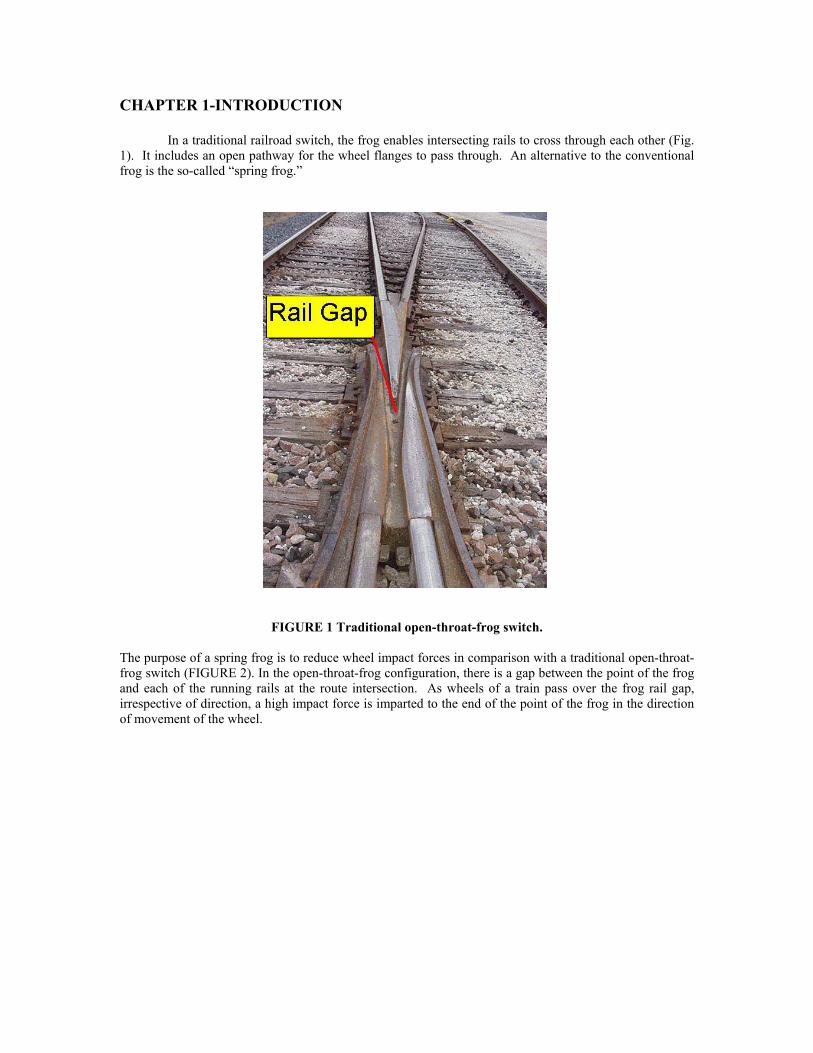
In a traditional railroad switch, the frog enables intersecting rails to cross through each other (Fig. 1). It includes an open pathway for the wheel flanges to pass through. An alternative to the conventional frog is the so-called “spring frog.”
FIGURE 1 Traditional open-throat-frog switch.
The purpose of a spring frog is to reduce wheel impact forces in comparison with a traditional open-throat-frog switch (FIGURE 2). In the open-throat-frog configuration, there is a gap between the point of the frog and each of the running rails at the route intersection. As wheels of a train pass over the frog rail gap, irrespective of direction, a high impact force is imparted to the end of the point of the frog in the direction of movement of the wheel.

2
FIGURE 2 Typical Spring Frog
In order to discuss operation of a spring frog (SF), the following nomenclature is provided to maintain
clarity. • Outside Running Rail: The rail that continues on in the direction of the route without
encountering other track work components (see FIGURE 2, items A and D). • Field Side Rail: Outside running rail. • Inside Running Rail: The rail that crosses the running rail of another route (see FIGURE 2,
items B and C). • Spring Rail: The moveable portion of the track that allows lateral displacement of the rail (see
FIGURE 2, item a) • Through Mainline Route: The portion of track occurring in a straight configuration (see
FIGURE 2, items A and B). • Through Route: Through mainline route. • Mainline Route: Through mainline route. • Diverging Route: The portion of track that has curvature that enables movement away from the
through mainline route (see FIGURE 2, items C and D). • Frog Casting: The portion of a switch where two rails cross (see FIGURE 2, item F) • Guard Rail: A short piece of rail (in comparison with the infinitely long running rail) that is
closely connected to a running rail providing a gap to act as a wheel flange guideway. This rail serves to keep the flange of the wheel at a close proximity to the running rail to which the guardrail is attached (see FIGURE 2, item E).
The spring rail is a component of the mainline running rail. When a train is operating on the through mainline route, the wheels are continuously in contact with the top of the rail as they cross over the point of the frog, irrespective of the train direction. This contact essentially eliminates the impact forces associated with the traditional open-throat-frog switch.
3
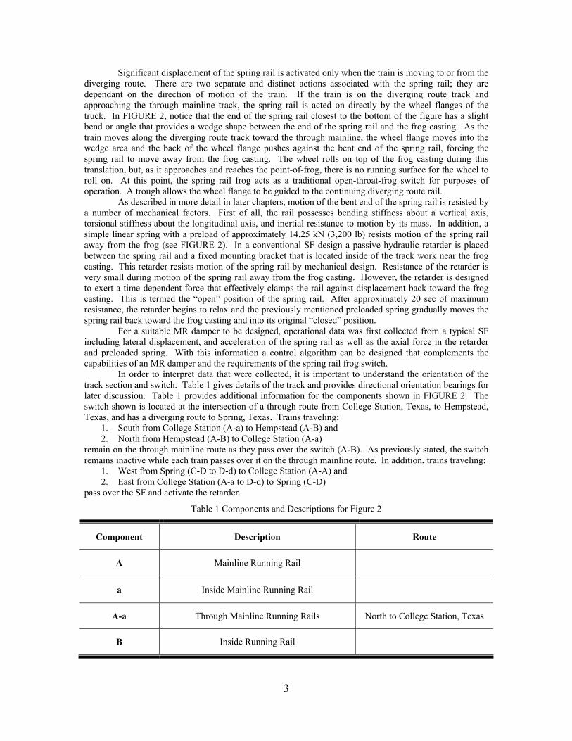
Significant displacement of the spring rail is activated only when the train is moving to or from the diverging route. There are two separate and distinct actions associated with the spring rail; they are dependant on the direction of motion of the train. If the train is on the diverging route track and approaching the through mainline track, the spring rail is acted on directly by the wheel flanges of the truck. In FIGURE 2, notice that the end of the spring rail closest to the bottom of the figure has a slight bend or angle that provides a wedge shape between the end of the spring rail and the frog casting. As the train moves along the diverging route track toward the through mainline, the wheel flange moves into the wedge area and the back of the wheel flange pushes against the bent end of the spring rail, forcing the spring rail to move away from the frog casting. The wheel rolls on top of the frog casting during this translation, but, as it approaches and reaches the point-of-frog, there is no running surface for the wheel to roll on. At this point, the spring rail frog acts as a traditional open-throat-frog switch for purposes of operation. A trough allows the wheel flange to be guided to the continuing diverging route rail.
As described in more detail in later chapters, motion of the bent end of the spring rail is resisted by a number of mechanical factors. First of all, the rail possesses bending stiffness about a vertical axis, torsional stiffness about the longitudinal axis, and inertial resistance to motion by its mass. In addition, a simple linear spring with a preload of approximately 14.25 kN (3,200 lb) resists motion of the spring rail away from the frog (see FIGURE 2). In a conventional SF design a passive hydraulic retarder is placed between the spring rail and a fixed mounting bracket that is located inside of the track work near the frog casting. This retarder resists motion of the spring rail by mechanical design. Resistance of the retarder is very small during motion of the spring rail away from the frog casting. However, the retarder is designed to exert a time-dependent force that effectively clamps the rail against displacement back toward the frog casting. This is termed the “open” position of the spring rail. After approximately 20 sec of maximum resistance, the retarder begins to relax and the previously mentioned preloaded spring gradually moves the spring rail back toward the frog casting and into its original “closed” position.
For a suitable MR damper to be designed, operational data was first collected from a typical SF including lateral displacement, and acceleration of the spring rail as well as the axial force in the retarder and preloaded spring. With this information a control algorithm can be designed that complements the capabilities of an MR damper and the requirements of the spring rail frog switch.
In order to interpret data that were collected, it is important to understand the orientation of the track section and switch. Table 1 gives details of the track and provides directional orientation bearings for later discussion. Table 1 provides additional information for the components shown in FIGURE 2. The switch shown is located at the intersection of a through route from College Station, Texas, to Hempstead, Texas, and has a diverging route to Spring, Texas. Trains traveling:
1. South from College Station (A-a) to Hempstead (A-B) and 2. North from Hempstead (A-B) to College Station (A-a)
remain on the through mainline route as they pass over the switch (A-B). As previously stated, the switch remains inactive while each train passes over it on the through mainline route. In addition, trains traveling:
1. West from Spring (C-D to D-d) to College Station (A-A) and 2. East from College Station (A-a to D-d) to Spring (C-D)
pass over the SF and activate the retarder.
Table 1 Components and Descriptions for Figure 2
Component Description Route
A Mainline Running Rail
a Inside Mainline Running Rail
A-a Through Mainline Running Rails North to College Station, Texas
B Inside Running Rail

4
A-B Mainline Running Rail and Inside Running Rail South to Hempstead, Texas
C Inside Running Rail
C-D Inside Running Rail and Diverging Running Rail East to Spring, Texas
d Inside Diverging Running Rail
D-d Diverging Route Running Rails Diverges to Mainline Running Rails
E Guard Rails
F Frog Casting
Maintenance costs for spring frogs (SF) are a major expense for the railroad industry, especially
replacing broken retarders. Since current retarders are not performing well, a more reliable and flexible damper is desired for SF installations. A reasonable estimate of the cost to the industry can be established by estimating the number of installed SF switches in the industry, the cost for a new retarder, the range of life expectancy for retarders and the labor cost of removing and installing a new retarder. There are estimated to be over 4,000 mainline SF switches in the US railroads. The average maintenance cost to replace a retarder is estimated to be equal to the purchase cost or $500.00. A conservative estimate for the overall cost to the industry for replacement of the passive retarder using a six-month life is an annual cost to the railroad industry of about $8 million.
There are several available methods to control motion of the spring rail in a SF installation. These include active control, passive control, and semi-active control. Active control, which involves an actuator, can be used to control the SF; however, difficulties associated with reliance on external power and system reliability have prevented implementation of this approach. Passive control, as currently used, has proven inefficient and costly. Therefore, it is postulated that a solution can be found in semi-active control strategies that combine the best features of both active and passive control approaches.
A variety of semi-active control devices have been proposed for mitigating the level of vibration in a structural system: variable orifice damper (5), variable stiffness device (6), smart tuned mass damper (7), variable-friction damper (8, 9, 10), and electrorheological (ER) damper (11, 12, 13).
Magnetorheological (MR) dampers have received significant attention in recent years because they can provide high reliability at a modest cost and provide fail-safe operation in case the control hardware malfunctions. Research related to reducing vibrations of dynamic systems using MR dampers first began with attempts to understand salient properties of an MR-damper (15, 16, 17, 18, 19, 20). Later research focused on investigating the response control of dynamic systems so that design guidelines could be developed (22, 23, 24, 25, 26). However, there is no published research on application of MR dampers for mitigation of train-induced vibrations or forces in a SF switch.
The rest of the report is organized as follows. In Chapter 2 the collection and analysis of experimental data in the field from an active SF that has (2) no passive retarder and (3) a conventional passive retarder is outlined. This is followed by Chapter 3 that describes procedures for design, fabrication, and testing of a custom prototype MR damper that is intended to replace a passive retarder based on the collected data. Numerous laboratory tests were performed on the prototype MR damper in a uniaxial testing machine to obtain a broad range of force levels for corresponding displacement and voltage signals. In Chapter 4, an on/off controller is developed to operate the MR retarder in an intelligent fashion. The results of the field application of the prototype MR damper in a revenue service SF switch are described in

5
Chapter 5. Conclusions and recommendations are provided in Chapter 6. As an aid to understanding the major components of this work, FIGURE 3 shows an overview of the entire research project.
FIGURE 3 Research Overview. CHAPTER 2-DATA ACQUISITION AND ANALYSIS
Prior to beginning work on this contact, several trips to collect SF switch data were conducted at a site on the Union Pacific Railroad in Navasota, Texas. The purpose of the trip was to instrument the SF in order to obtain real time data during passage of moving trains. The fastest train was traveling at an estimated maximum speed of 40 km/hr (25 mi/hr). The SF switch at the site was equipped with fixtures for a retarder; however, no retarder was present (see FIGURE 4). The weather was fair with overcast skies and the temperature was approximately 23.8°C (75°F).
DATA Acquisition
Design & Fabrication Nonparametric Modeling
Performance and Robustness
Data Analysis
Control Algorithm Development MR Damper Development
Operational Frog Switch Load Cell Accelerometer LVDT
Field Test
Digital Signal Processing Neuro-Fuzzy Algorithm
Time Domain Frequency Domain Time-Frequency Analysis

6
FIGURE 4 Retarder mounting brackets near spring rail.
Collected data included lateral displacement and acceleration. Since a retarder was not installed at
this location, force data were not collected on this field trip. dSPACE software (version 3.1) and hardware were used for data acquisition. This data acquisition system converts voltage signals from LVDT and accelerometer transducers into stored digital output at a rate of 500 Hz. LVDT and accelerometer transducers measure the displacement and acceleration of the spring rail, respectively. Velocity of the spring rail at the location of the LVDT is derived by applying the backward difference formula of the displacement data as given by the LVDT. The equation used to calculate these values is as follows (27):
1 23 42
k k kF F FdFdt t
− −− +=
∆ (1)
Both transducers were attached to the spring rail by making use of the retarder brackets (see FIGURE 5). Placement of these transducers in the same location where a retarder would be installed was done to obtain a close approximation to data that would be collected if a retarder were in place. In previous data collection attempts on an earlier field trip the transducer mounting setup came loose due to the unexpected magnitude of vibrations caused by the train. Vibrations violently shook the steel mounting bar until the mechanical clamps released after approximately one minute of data collection.

7
FIGURE 5 LVDT and accelerometer transducer attached to the spring rail.
DATA ACQUISITION WITH RETARDER IN PLACE A 22.24 kilo-Newton (kN) (5,000 pound force) (lbf) load pin was acquired to measure the force load of the SF spring rail and the single coil spring box in the switch. A new standard passive retarder was also acquired to gather real time data from the SF with the retarder in place. The SF was equipped with the retarder, the load pin, the LVDT and the accelerometer to collect data (see Figure 6.) The static force was measured with a Union Pacific hydraulic pump and slave wedge. The recorded static force was 13.34 kN (3,000 lbf) indicated on the apparatus’ indicator gauge. The UP specifications for the maximum static force allowed on the switch being used for the test was 14.23 kN (3,200 lbf) and a minimum allowable force of 12.90 kN (2,900 lbf).
FIGURE 6 A passive retarder in the Navasota SF with data acquisition transducers.
8
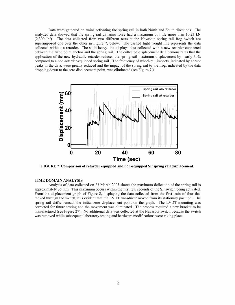
Data were gathered on trains activating the spring rail in both North and South directions. The analyzed data showed that the spring rail dynamic force had a maximum of little more than 10.23 kN (2,300 lbf). The data collected from two different tests at the Navasota spring rail frog switch are superimposed one over the other in Figure 7, below. The dashed light weight line represents the data collected without a retarder. The solid heavy line displays data collected with a new retarder connected between the fixed point anchor and the spring rail. The collected displacement data demonstrates that the application of the new hydraulic retarder reduces the spring rail maximum displacement by nearly 30% compared to a non-retarder-equipped spring rail. The frequency of wheel-rail impacts, indicated by abrupt peaks in the data, were greatly reduced and the impact of the spring rail to the frog, indicated by the data dropping down to the zero displacement point, was eliminated (see Figure 7.)
TIME DOMAIN ANALYSIS
Analysis of data collected on 23 March 2003 shows the maximum deflection of the spring rail is approximately 35 mm. This maximum occurs within the first few seconds of the SF switch being activated. From the displacement graph of Figure 8, displaying the data collected from the first train of four that moved through the switch, it is evident that the LVDT transducer moved from its stationary position. The spring rail drifts beneath the initial zero displacement point on the graph. The LVDT mounting was corrected for future testing and the movement was eliminated. The process required a new bracket to be manufactured (see Figure 27). No additional data was collected at the Navasota switch because the switch was removed while subsequent laboratory testing and hardware modifications were taking place.
0 20 40 60 800
20
40
60
Time (sec)
Dis
plac
emen
t (m
m) Spring rail w/o retarder
Spring rail w/ retarder
0 20 40 60 800
20
40
60
Time (sec)
Dis
plac
emen
t (m
m) Spring rail w/o retarder
Spring rail w/ retarder
FIGURE 7 Comparison of retarder equipped and non-equipped SF spring rail displacement.

9
0 20 40 60 80 100-11
010203040
Time (sec)
Dis
plac
emen
t (m
m)
0 20 40 60 80 1000
2
4
6
8
Time (sec)
Acc
eler
atio
n (m
/s2 )
0 20 40 60 80 100-47
-200
20
47
Time (sec)
Velo
city
(mm
/s)
FIGURE 8 Time history of displacement, velocity, and acceleration from Train number 1.
Using a digital Infinite Impulse Response (IIR) filter of the form (36):
1 20 1 2
1 20 1 2
( )m
mn
n
b b z b z b zH za a z a z a z
− − −
− − −
+ + +=
+ + +L
L (2)

10
an absolute value of the frequency response was developed. Inserting an exponential term into the complex value z, the following frequency response is obtained.
( ) jwz eH z
= (3) Taking the absolute value of Equation (2) generates the magnitude of the frequency response.
In this project, an IIR digital filter has been designed as follows:
4 3 2
4 3 20.0004 0.0017 0.0025 0.0017 0.0004( )
3.1806 3.8612 2.1122 0.4383z z z zH z
z z z z+ + + +
=− + − + (4)
in which z is a complex variable that represents a complex plane. FIGURE 9 shows a 10 sec filtered segment of data from passage of the third train so that a more
detailed understanding of the track movement can be established. It can be seen that the maximum displacement of the spring rail is approximately 55 mm. Peak displacements of the spring rail occur near the beginning of the data collection since the locomotive truck leading the train has the largest wheel flange. Velocities vary between ± 50 mm/s and the peak acceleration is approximately 2 m/s2. The time-displacement graph shows the spring rail returns to its initial position after each wheel of a car truck has passed when a retarder is not present. Additionally, passage of each car can be identified by a delay in the displacement signal (see FIGURE 9.)
12 14 16 18 20 22-50
0
50
100
Time (sec)
Dis
plac
emen
t (m
m)
12 14 16 18 20 22-2
0
2
4
Time (sec)
Acc
eler
atio
n (m
/s2 )
12 14 16 18 20 22-50
0
50
Time (sec)
Velo
city
(mm
/s)
FIGURE 9 Short segment of filtered data from passage of train 3.
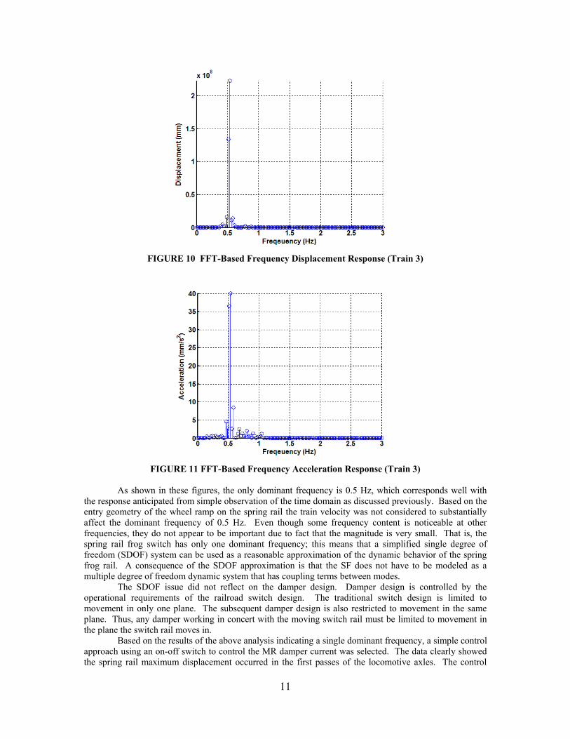
FREQUENCY DOMAIN ANALYSIS Recall the time domain response as shown in FIGURE 9. The signal pattern appears to have a
dominant period of approximately 2 sec (0.5 Hz). FIGURE 10 and FIGURE 11 show results of a Fast Fourier Transform (FFT) that yields power spectrums of the displacement time-history for passage of Train 3 (28).
11
FIGURE 10 FFT-Based Frequency Displacement Response (Train 3)
FIGURE 11 FFT-Based Frequency Acceleration Response (Train 3)
As shown in these figures, the only dominant frequency is 0.5 Hz, which corresponds well with
the response anticipated from simple observation of the time domain as discussed previously. Based on the entry geometry of the wheel ramp on the spring rail the train velocity was not considered to substantially affect the dominant frequency of 0.5 Hz. Even though some frequency content is noticeable at other frequencies, they do not appear to be important due to fact that the magnitude is very small. That is, the spring rail frog switch has only one dominant frequency; this means that a simplified single degree of freedom (SDOF) system can be used as a reasonable approximation of the dynamic behavior of the spring frog rail. A consequence of the SDOF approximation is that the SF does not have to be modeled as a multiple degree of freedom dynamic system that has coupling terms between modes.
The SDOF issue did not reflect on the damper design. Damper design is controlled by the operational requirements of the railroad switch design. The traditional switch design is limited to movement in only one plane. The subsequent damper design is also restricted to movement in the same plane. Thus, any damper working in concert with the moving switch rail must be limited to movement in the plane the switch rail moves in.
Based on the results of the above analysis indicating a single dominant frequency, a simple control approach using an on-off switch to control the MR damper current was selected. The data clearly showed the spring rail maximum displacement occurred in the first passes of the locomotive axles. The control

12
algorithm developed used a discrete counter of the spring rail movements exceeding a one inch opening. After the spring rail had opened eight times the control algorithm switched the current in the piston coil to the maximum on condition of 2 amperes at 24 volts DC.
CHAPTER 3-MAGNETORHEOLOGICAL DAMPER DESIGN
The design, fabrication, and modeling of a MR damper that was custom-made for installation in a SF are reviewed. Several important design parameters were established from the previous data collection efforts. The maximum stroke of the MR damper was established from the minimum and maximum permissible displacement of the spring frog. Measurement of the displacement of the spring rail from a fresh mark on the rail tie (see FIGURE 4) showed a maximum of 63 mm (2.5 in.) of motion at the location of the retarder. In order to avoid accidental undue stress on the bearings and to be conservative the piston of the MR damper was designed to have a maximum stroke of 101.6 mm (4 in.). The cylinder would be mounted offset from the inline mounting brackets of the original manufacturer due to the through cylinder piston rods.
An initial HSR-46 project Expert Panel meeting was held on 22 April 2004. The researchers reviewed the necessity for the offset retarder adapter brackets with the Expert Panel. The offset design was considered to only be applicable to the initial prototype model. If the technology proved to be viable, future designs would be manufactured so that the piston rods would be axially mounted inline with the spring rail and fixed tie brackets. The Expert Panel considered the offset to be problematic with regard to the potential to introduce undesirable bending loads on the spring rail. The researchers agreed to review this issue with the switch manufacturer and railroad experts in switch design and loading.
The offset issue was reviewed with Union Pacific Railroad Engineering Department representatives with expertise in both design and field applications of spring rail frog switches. The conclusion of the UP engineer and the TTI researchers was that the spring rail would not be subject to undue or restrictive restraint by the offset of the MR Damper bracket. The conclusion of the UP engineers was that the forces of passing trains would far outweigh any forces introduced by the offset design for connecting the MR Damper to the switch mechanism.
The diameters of the piston and piston rods were determined. The Lord Corporation has proprietary technology to determine the electric coil needed to generate the optimal magnetic field on the optimal piston size to produce the retarding force desired in a MR fluid cylinder. Lord Corporation recommended a piston, cylinder, and piston-to-cylinder wall gap with a two stage coil for this application. A piston with a diameter of 99.6 mm (3.921 in.) and a piston rod with a diameter of 25 mm (0.984 in.) were found to be best suited to meet operational requirements and are available from a commercial manufacturer of hydraulic cylinders.
A cylindrical casing that has an inner diameter of 101.6 mm (4 in.) and a length of 165 mm (6.496 in.) was obtained from Parker Bowles Corporation. In addition, appropriate mounting fixtures, brass bearings, and tie rods were selected from a catalog of hydraulic hardware. Figure 12 illustrates the MR damper design and adapter brackets as an assembly.

13
FIGURE 12 Side View of the Designed MR Damper
Dimensions of the staging for the piston are based on design parameters for the damper. For this
project, Lord Corporation provided the design specifications of the staging for the piston as given in Table 2. Table 2 Lord Corporation recommended design parameters for MR damper.
Parameter Classification Design Parameter Numerical Value Number of stages 2
Number of turns per layer 203 Number of layers/coil 35
Length of wire per stage (m) 50.23 Core configuration
Wire gage 25 AWG Current 4 A
Coil resistance per stage 11.9 ohms (8.6 measured) Inductance 0.13 H
Voltage 11.89 V Power 47.57 W
Electrical Properties
Hgap (kA/m) 170 kA/m
FABRICATION The manufacturer fabricated the piston and rod assembly as specified by the research team. The
coil slots and holes are shown as supplied. Two holes were drilled through the piston to the center of the rod and from the end of the rod to the center hole (see Figure 13).

14
FIGURE 13 Piston Head with a Drilled Hole
The opening of the pilot hole is sealed with a custom-designed plug to prevent loss of MR fluid
during operation of the damper (FIGURE 13). The plug is designed to withstand high operational pressures inside the damper; also the material used for fabrication of the plug does not react with the MR fluid. One of the three wires shown in FIGURE 14 is clipped off while the other two wires serve as a pass-through for the current.
FIGURE 14 Custom Designed Plug
FIGURE 15 shows the modified two-stage piston and rod with a coil of electromagnetic wire
wound around it.
15
FIGURE 15 Wire Wound on Stages of Piston
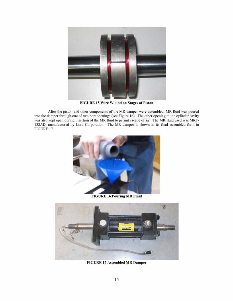
After the piston and other components of the MR damper were assembled, MR fluid was poured
into the damper through one of two port openings (see Figure 16). The other opening to the cylinder cavity was also kept open during insertion of the MR fluid to permit escape of air. The MR fluid used was MRF-132AD, manufactured by Lord Corporation. The MR damper is shown in its final assembled form in FIGURE 17.
FIGURE 16 Pouring MR Fluid
FIGURE 17 Assembled MR Damper

16
PERFORMANCE TESTS Testing Input Signal Generation
After the damper was fabricated and assembled, a series of performance tests was conducted. The purpose of these tests was to gather sufficient data to determine the operational capabilities of the damper and to create a fuzzy inference system that would be used in later numerical simulations. Data collected during the tests would provide a sufficient number of input and output sets such that the entire operational range of displacement, velocity, and voltage applied to the MR damper in an operational SF would be represented.
Testing of the MR damper in the MTS machine in the “passive on” mode demonstrated the damper’s capability to maintain a substantial load under varying positive and negative force changes. The “passive on” mode is the application of a constant current to the MR Damper coils regardless of velocity and direction of the piston. The design resistance force of the damper was calculated by the Lord Corporation to be 21-22 kN in the “passive on” mode, see Appendix A. The load applied to the damper was in excess of 10 kiloNewtons and the applied current was less than 2 amperes. The test data showed the load holding capability of the damper to be relatively constant under the varying spring rail load as collected from the Navasota switch site (see Figure 18.) Figure 18 is the composite of two data sets, the MR Damper graph is the force resisted by the damper in the “passive on” mode and the Retarder graph is the spring rail force data collected from the Navasota SRF switch.
FIGURE 18 MR Damper passive on load strength compared to the impressed load of the
Navasota spring rail loading data.
Data Acquisition Testing the MR damper in a uniaxial testing machine involved holding one end fixed while
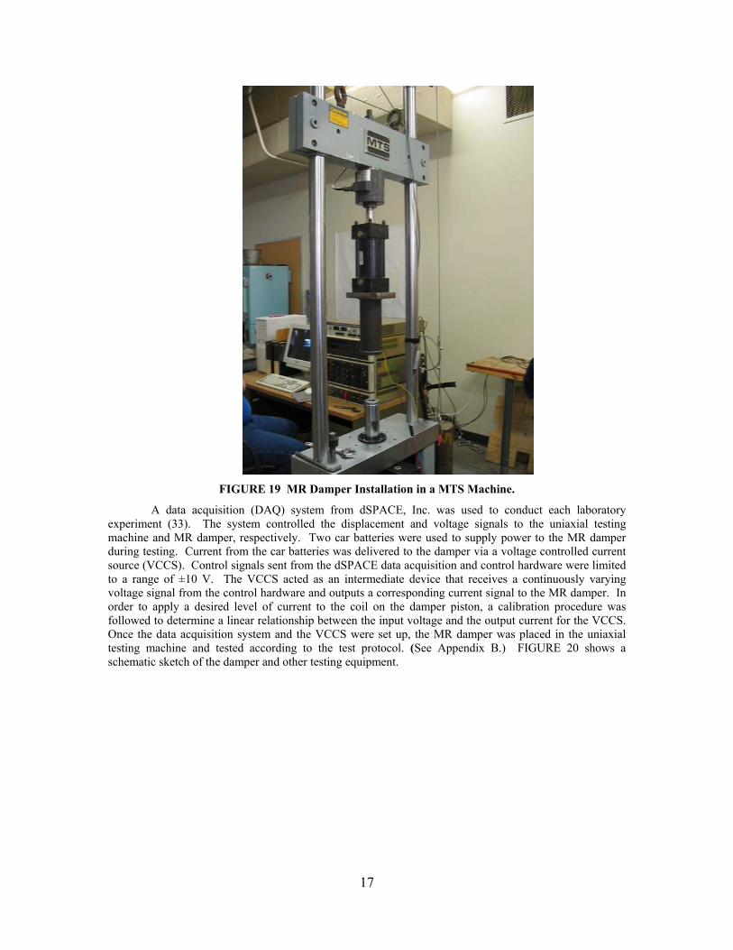
applying a specified displacement at various frequencies and amplitudes to the other end. In this case, the upper rod of the damper is screwed into a load cell of an MTS uniaxial testing machine (see FIGURE 19). The lower end of the piston rod has to be allowed free movement for operation of the damper. A special steel attachment fixture was designed that encapsulates the bottom end of this rod and provides free space for its movement. This fixture also connects the MR damper to the base of the uniaxial testing machine that controls movement of the piston relative to the hydraulic cylinder.
0 10 20 30 40 50
0
2
4
6
8
10
Time (sec)
Forc
e (k
N)
Retarder MR Damper
17
FIGURE 19 MR Damper Installation in a MTS Machine.
A data acquisition (DAQ) system from dSPACE, Inc. was used to conduct each laboratory experiment (33). The system controlled the displacement and voltage signals to the uniaxial testing machine and MR damper, respectively. Two car batteries were used to supply power to the MR damper during testing. Current from the car batteries was delivered to the damper via a voltage controlled current source (VCCS). Control signals sent from the dSPACE data acquisition and control hardware were limited to a range of ±10 V. The VCCS acted as an intermediate device that receives a continuously varying voltage signal from the control hardware and outputs a corresponding current signal to the MR damper. In order to apply a desired level of current to the coil on the damper piston, a calibration procedure was followed to determine a linear relationship between the input voltage and the output current for the VCCS. Once the data acquisition system and the VCCS were set up, the MR damper was placed in the uniaxial testing machine and tested according to the test protocol. (See Appendix B.) FIGURE 20 shows a schematic sketch of the damper and other testing equipment.

18
FIGURE 20 Schematic sketch of the MR damper testing setup.
Test Results
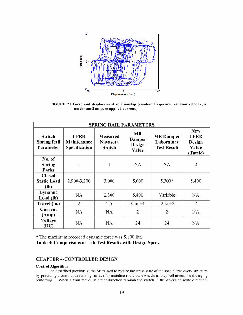
The input signal generation and data acquisition system are discussed above. The following graph illustrates the extent of the force that the MR damper develops with respect to constant current in the displacement control mode (see Figure 21). Each sinusoidal and random experiment was conducted for a total of 40 sec with a time step of 0.002 sec for all tests. That is, ten thousand data points for the sinusoidal signal and twenty thousand data points for the random signal were recorded for displacement, velocity, current, and force.
Table 3 Summarizes the MR Damper laboratory tests results, and compares them with UPRR maintenance specifications, the initial static field measurements, and the MR Damper design valve.
19
FIGURE 21 Force and displacement relationship (random frequency, random velocity, at maximum 2 ampere applied current.)
SPRING RAIL PARAMETERS
Switch Spring Rail Parameter
UPRR Maintenance Specification
Measured Navasota
Switch
MR Damper Design Value
MR Damper Laboratory Test Result
New UPRR Design Value
(Tatsie) No. of Spring Packs
1 1 NA NA 2
Closed Static Load
(lb) 2,900-3,200 3,000 5,000 5,300* 5,400
Dynamic Load (lb) NA 2,300 5,800 Variable NA
Travel (in.) 2 2.5 0 to +4 -2 to +2 2 Current (Amp) NA NA 2 2 NA
Voltage (DC) NA NA 24 24 NA
* The maximum recorded dynamic force was 5,800 lbf. Table 3: Comparisons of Lab Test Results with Design Specs CHAPTER 4-CONTROLLER DESIGN Control Algorithm
As described previously, the SF is used to reduce the stress state of the special trackwork structure by providing a continuous running surface for mainline route train wheels as they roll across the diverging route frog. When a train moves in either direction through the switch in the diverging route direction,

20
analysis of collected data showed that the spring rail periodically impacts the switch frog. Ideally, when a train negotiates through the SF on the diverging route the spring rail should be caught and held in the open position while the train is moving through it. Likewise, after all wheels of the train have passed the SF, the holding power should be removed as quickly and smoothly as reasonable. Therefore, it is critically important to determine the instant at which the running rail should be caught and released, respectively. Between these two critical instances the rail should be held in the ‘open’ position.
In this section, an algorithm for control of the spring rail motion is presented. The fundamental approach is to employ a short-time Fourier transform (STFT) and a Hilbert transform (HT) algorithm to create a robust control system. FIGURE 22 shows a schematic diagram of the control software program.
FIGURE 22 Schematic Diagram of SF Control Software
For field test monitoring and data acquisition purposes, a LVDT and an accelerometer were
attached to the spring rail. However, only data from a LVDT were used for preliminary purposes of design of the controller software. Further refinements of the prototype should also include accelerometer data in the control algorithm to make the control system more robust.
Collected data were converted to be compatible with PC processing at a 0.002 second sample rate and were processed by the STFT and HT algorithms. The STFT algorithm was used to extract the magnitude of the time domain signal for a short time. The HT algorithm was used to determine the instantaneous frequency. These processed signals go to a logic function block. This control logic is implemented in a Simulink code as shown in FIGURE 23.
FIGURE 23 Simulink Diagram for Control of SF Motion
Decisions made inside of the logic block use the AND operator. In the logic function block, the
following four cases are taken into account: Case 1: Spring rail is not displaced and impact force is not imparted by a train wheel. Case 2: Spring rail is displaced and impact force is not imparted by a train wheel. Case 3: Spring rail is not displaced and impact force is imparted by a train wheel. Case 4: Spring rail is displaced and impact force is imparted by a train wheel.

21
Case 1 occurs when a train is not passing over the diverging route; Case 2 is encountered after all wheels of the train have passed the SF through the diverging route and the MR damper is still holding the spring rail in the ‘open’ position (i.e. the rail is in a deformed position) using full power; Case 3 takes into account unexpected vibration; and Case 4 occurs when wheels of the train are passing over the frog-running rail gap. However, note that Case 3 is also sensed when any vibration information is sensed. This case might occur, for example, due to energy from an approaching train.
Laboratory Testing of Controller
Before laboratory tests were conducted, numerical simulations were carried out using dSpace ControlDesk. Design parameters such as the length of the window and the sampling time were established so that severe time delay problems would not occur. After the parameters had been approximated with reasonable values, laboratory testing of the actual hardware began.
FIGURE 24 shows the displacement signal that was measured from the motion of the Navasota spring rail during train movement. Also, shown in the figure is the associated voltage signal that was used to provide current to the MR damper. In order to illustrate results from laboratory testing, an LVDT was set to an initial displacement reading of 0 mm. This represented the ‘closed’ position of the spring rail. After a wait period of approximately 12 sec the LVDT is suddenly displaced to approximately 58 mm; however, the controller program waits to send a voltage signal to the MR damper. The wait occurs because the collected data must be converted and processed by the STFT and HT algorithms. After approximately 3 seconds, the controller logic recognizes that the spring rail has reached its maximum displacement value and sends a voltage signal to the VCCS to turn on the maximum current that goes to the damper. The maximum current in the damper coil causes its resistance to motion to be a large value. The applied logic is that the control force is to be maximized when either the magnitude of the vibration is greater than 10 mm or a phase lag in the vibration information exists. Notice that even if the displacement is maximized as for example between 40 and 50 sec, that the voltage signal is not activated because information on the phase angle is not available. However, the voltage signal is maximized for a very short-time between 51 and 52 sec even though the phase angle is not activated. This situation occurs because the phase angle of the vibration is changed during closing of the spring rail. Moreover, the time delay for this process is not large and can be adjusted if necessary.
FIGURE 24 Displacement and Associated Control Voltage
MR DAMPER CURRENT ON/OFF OPERATION MTS Machine Force Control Mode A simple control algorithm for turning on the coil current was developed. The new control method is based on the above logic displacement controller of the spring rail. Recall that the spring rail

22
moves through a longer distance when the locomotives move through the SF area than when cars pass through. Also recalling that the spring rail operates in a single frequency mode regardless of train speed, the use of a displacement-based algorithm to control coil current appeared to be valid. An algorithm was developed and tests were carried out in the MTS to validate the holding force capability of the MR damper. Figure 18 shows the MR damper in the MTS test machine. A test using a constant 2 ampere current applied to the piston coil with successive applications of 0.89 kN (200 lbf) at each step shows that the damper has an initial displacement as each increment of force is applied, but then holds the force without movement until the next increment is applied. A graph showing the holding capability of the damper in force control demonstrates the validity of using the MR technology to hold the SF spring rail open (see FIGURE 25.)
FIGURE 25 MTS machine in force control mode demonstrates zero displacement with
stepwise increased coil current.
MTS Machine Displacement Control Mode The MTS machine was placed in displacement control mode operating at a frequency of 0.01 Hz with a displacement of 1 cm. After several cycles a 2 ampere current was applied to the piston coil while it was moving in the positive direction. The test was repeated in the negative direction after two passive cycles. The graph displayed in FIGURE 26 shows that the damper has a nearly symmetrical force capability of 23.57 kN (5,300 lbf) and a maximum force of nearly 25.20 kN (5,800 lbf). Additionally, the graph indicates the force required to move the cylinder in a passive off condition is consistently 1.56 kN (350 lbf).
-30000
-20000
-10000
0
10000
20000
30000
0 20 40 60 80 100 120 140
time (s)
Forc
e (N
)
FIGURE 26 MTS machine in displacement control mode and a 2 ampere coil current
demonstrates force capability of approximately -25.2 kN (-5,600 lbf).
-0.2
0
0.2
0.4
0.6
0.8
1
1.2
1.4
0 10 20 30 40 50 60 70 80 time (s)
Dis
plac
emen
t (cm
)
23
CHAPTER 5-FIELD TESTING AND EXPERIMENTAL RESULTS MR DAMPER TESTING AT TATSIE, TEXAS
The field test site used for the initial data acquisition, in Navasota, Texas, had to be changed due to the removal of the spring frog. Accordingly, Union Pacific arranged for a second test site location equipped with a spring frog at Tatsie, Texas.
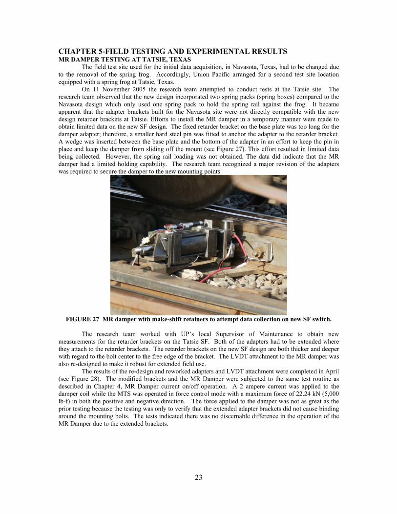
On 11 November 2005 the research team attempted to conduct tests at the Tatsie site. The research team observed that the new design incorporated two spring packs (spring boxes) compared to the Navasota design which only used one spring pack to hold the spring rail against the frog. It became apparent that the adapter brackets built for the Navasota site were not directly compatible with the new design retarder brackets at Tatsie. Efforts to install the MR damper in a temporary manner were made to obtain limited data on the new SF design. The fixed retarder bracket on the base plate was too long for the damper adapter; therefore, a smaller hard steel pin was fitted to anchor the adapter to the retarder bracket. A wedge was inserted between the base plate and the bottom of the adapter in an effort to keep the pin in place and keep the damper from sliding off the mount (see Figure 27). This effort resulted in limited data being collected. However, the spring rail loading was not obtained. The data did indicate that the MR damper had a limited holding capability. The research team recognized a major revision of the adapters was required to secure the damper to the new mounting points.
FIGURE 27 MR damper with make-shift retainers to attempt data collection on new SF switch.
The research team worked with UP’s local Supervisor of Maintenance to obtain new measurements for the retarder brackets on the Tatsie SF. Both of the adapters had to be extended where they attach to the retarder brackets. The retarder brackets on the new SF design are both thicker and deeper with regard to the bolt center to the free edge of the bracket. The LVDT attachment to the MR damper was also re-designed to make it robust for extended field use. The results of the re-design and reworked adapters and LVDT attachment were completed in April (see Figure 28). The modified brackets and the MR Damper were subjected to the same test routine as described in Chapter 4, MR Damper current on/off operation. A 2 ampere current was applied to the damper coil while the MTS was operated in force control mode with a maximum force of 22.24 kN (5,000 lb-f) in both the positive and negative direction. The force applied to the damper was not as great as the prior testing because the testing was only to verify that the extended adapter brackets did not cause binding around the mounting bolts. The tests indicated there was no discernable difference in the operation of the MR Damper due to the extended brackets.

24
FIGURE 28 Extended adapter brackets and robust LVDT mount.
CONTINUED FIELD TESTING AT THE TATSIE SF SWITCH
In early September 2006 attempts were made to install the MR damper in the SF at Tatsie. It was evident that the revised adapters were too tight and had to be relieved. The modifications necessary were made over the next several days. The damper was installed in the Tatsie SF on 14 September 2006. The UP Track Inspector agreed to allow the damper to remain in place to verify its ability to withstand the operating environment of an active SF switch (between 20 and 45 trains per day.)
On 26 September 2006 TTI received a telephone call from the Track Inspector informing us that the MR damper fixed position retaining bolt had sheared in two and the damper had fallen out of the bracket. TTI proceeded to the Tatsie crossover and found a bolt retaining pin had sheared allowing the bolt to fall out of the bracket. No apparent damage had occurred to the switch, the brackets or the MR damper. The bolt was re-installed and a new retaining pin was inserted in the bolt. This same event occurred again on 5 October 2006 and repairs were carried out on 6 October 2006.
The reason the bolt retaining pin sheared off was determined to be the result of a design compromise made to enable the MR adapter bracket to be affixed to the basic SRF retarder brackets, as well as the new design of the Tatsie switch. The new fixed position bracket was materially thicker than the design employed in Navasota. In order to modify the MR damper adapter bracket to the fixed position bracket, the retaining bolt was shortened and the head thickness was reduced. The bolt retaining pin was applied to the bolt in a keyway-like groove. Because the bolt was shortened there was no longer enough bolt length for the pin to be properly spread open to keep it in place. The bolt retaining pin eventually worked its way back out of the bolt pin hole and allowed the bolt to toggle in the adapter bracket hole.
25
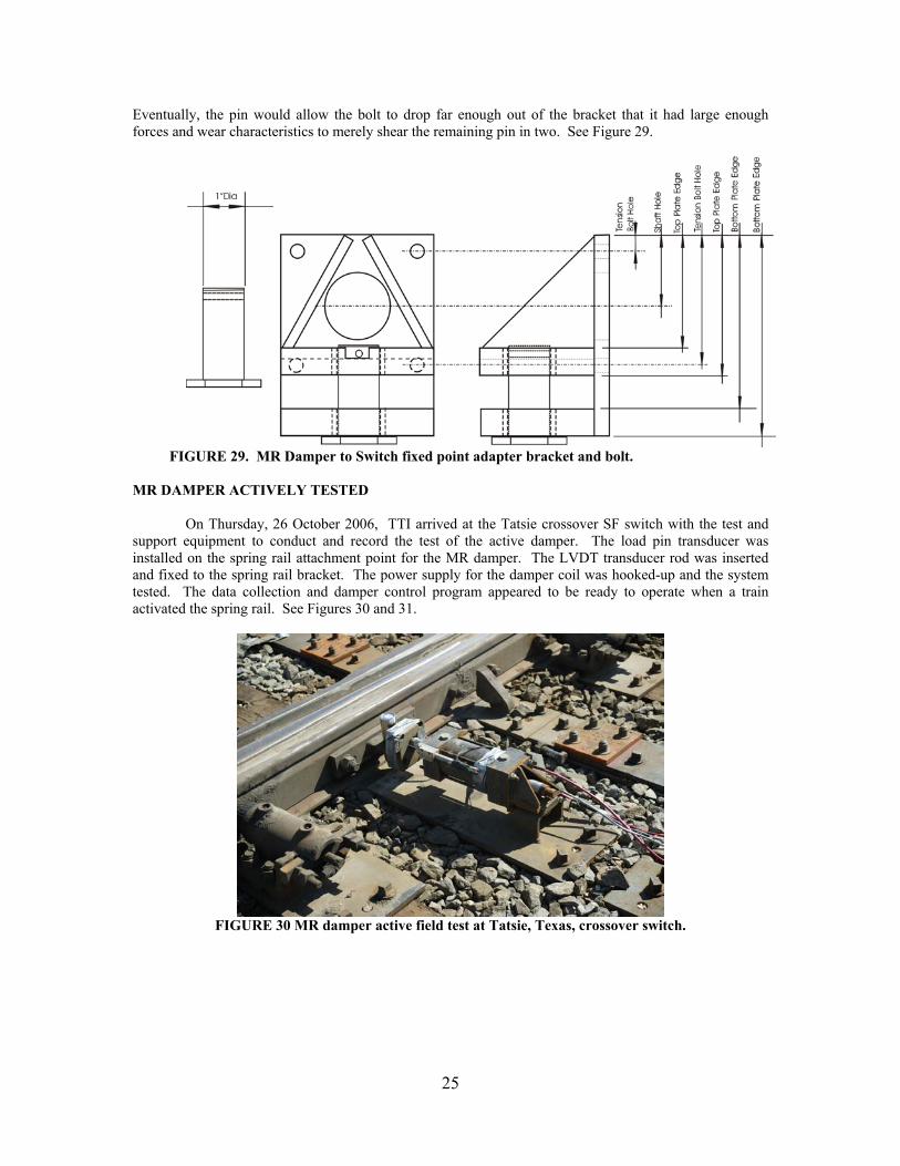
Eventually, the pin would allow the bolt to drop far enough out of the bracket that it had large enough forces and wear characteristics to merely shear the remaining pin in two. See Figure 29.
FIGURE 29. MR Damper to Switch fixed point adapter bracket and bolt.
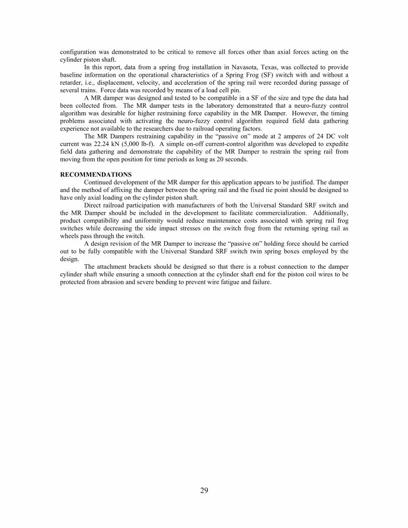
MR DAMPER ACTIVELY TESTED On Thursday, 26 October 2006, TTI arrived at the Tatsie crossover SF switch with the test and support equipment to conduct and record the test of the active damper. The load pin transducer was installed on the spring rail attachment point for the MR damper. The LVDT transducer rod was inserted and fixed to the spring rail bracket. The power supply for the damper coil was hooked-up and the system tested. The data collection and damper control program appeared to be ready to operate when a train activated the spring rail. See Figures 30 and 31.
FIGURE 30 MR damper active field test at Tatsie, Texas, crossover switch.

26
FIGURE 31 Data collection and MR damper control equipment.
MR Damper Shaft Failure The first train arrival was from the Giddings Subdivision onto the Navasota main track; referring to Figure 29, the train passed from left to right entering from the diverging route on the SF. After the locomotives passed the MR damper coil was energized with 2 amperes of direct current. The researchers were watching the action of the spring rail to observe whether it was held open rather than watching the data collection computer screen. Within moments of the first cars, the spring rail appeared to stop in the open position. However, the spring rail began to again move freely after a very short time period. Then the whole damper began to bounce from side-to-side and up and down. After the train had departed, the damper was inspected. The spring rail end of the damper shaft was separated at the adapter bracket. See Figure 32.
FIGURE 32 MR damper in Tatsie, Texas SF switch after shaft failure.
The data collection equipment recorded some data. Attempts were made to recover the data collected; however, all the data had substantial noise and therefore it was not useable. Filtering has not been successful at removing the noise from the data.

27
Examination of the shaft failure is clearly indicative of fatigue fracture (see Figure 33.) Reviewing the graph in Figure 25, the passive force required to move the piston in the cylinder was consistently 1.56 kN (350 lbf). The damper was in the Tatsie SF for approximately six weeks prior to being actively tested. The average daily number of trains moving through the Tatsie crossover SF was estimated to be 20. If it is assumed that the average train had 110 cars and two six axle locomotives there would have been 224 spring rail and MR damper cycles per train. At 20 trains per day for six weeks, the MR damper could have been cycled up to 379,600 times.
( )
600,379)221102076(
..
≅×××××≅
+×××××≅
cyclesCylindercyclesCylinder
CyclePullPush
CarTrucksofNo
TrainCarsofNo
DayTrains
WeekDaysWeekscyclesCylinder
Each cycle would have applied a positive or negative bending about the piston rod where it was attached to the mounting adapter. The moment arm was 6.3 cm (0.063 m). The magnitude of the force applied to the end of the piston shaft during each cycle of the spring rail would only have been 98.3 Nm (73 lb-ft). However, the application of even 98.3 Nm of bending for nearly 380,000 cycles could be expected to cause fatigue induced stress.
FIGURE 33 MR damper piston shaft fatigue fracture at adapter bracket face.
When the damper was actively tested by applying the 2 ampere current the force exerted on the cylinder piston shaft would have been approximately 1.63 kN (1,200 lb-ft) of bending in addition to 25.80 kN (5,800 lbf) shear force pushing or pulling on the piston shaft. The fracture clearly indicates fatigue fracture by the dark crescent moon shapes at both the top and bottom edges of the fracture (see Figure 33.)

28
Considering the mounting and attachment method of the MR Damper required in the western railroads Universal Standard SRF switch design (see Figure 34) a free body diagram was constructed (Figure 35.)
Attachment point
Shaft and Rail motion/Piston2 ”Bending Moment1
2/
The free body diagram is comprised of three primary elements, the freely moving cylinder shaft,
the adapter bracket affixed to the end of the shaft, and the spring rail force. The cylinder shaft is viewed as a fixed anchor for a cantilever beam problem. The adapter bracket is the equivalent of a cantilever beam of fixed length and the spring rail force is a point load at the end of the beam. A straight forward failure analysis of the free body diagram indicates the forces of the spring rail acting in shear at the cantilever beam fixed anchor will push and pull in the direction of movement for the cylinder shaft. However, the bending moment at the anchor point of the adapter bracket (beam) is not relieved. The bending moment for the Navasota SRF switch force was not considered to be significant at 0.9 kN of bending when the current was applied. The researchers did not evaluate the bending moment potential in the Tatsie switch because the static force was unknown.
Piston Shaft
Adapter Bracket
Spring Rail Force
M
V
CHAPTER 6-CONCLUSIONS AND RECOMMENDATIONS CONCLUSIONS
This investigation indicates that the application of magnetorheological technology to a railroad spring frog has promising potential. The principals are sound for the application; however, the design
FIGURE 35 Free body diagram of MR Damper Shear and Bending Moment acting on the cylinder shaft.
FIGURE 34 Diagram of MR Damper attachment to the spring rail and retarder anchor points, including the associated bending moment due to offset.
29
configuration was demonstrated to be critical to remove all forces other than axial forces acting on the cylinder piston shaft.
In this report, data from a spring frog installation in Navasota, Texas, was collected to provide baseline information on the operational characteristics of a Spring Frog (SF) switch with and without a retarder, i.e., displacement, velocity, and acceleration of the spring rail were recorded during passage of several trains. Force data was recorded by means of a load cell pin.
A MR damper was designed and tested to be compatible in a SF of the size and type the data had been collected from. The MR damper tests in the laboratory demonstrated that a neuro-fuzzy control algorithm was desirable for higher restraining force capability in the MR Damper. However, the timing problems associated with activating the neuro-fuzzy control algorithm required field data gathering experience not available to the researchers due to railroad operating factors.
The MR Dampers restraining capability in the “passive on” mode at 2 amperes of 24 DC volt current was 22.24 kN (5,000 lb-f). A simple on-off current-control algorithm was developed to expedite field data gathering and demonstrate the capability of the MR Damper to restrain the spring rail from moving from the open position for time periods as long as 20 seconds. RECOMMENDATIONS
Continued development of the MR damper for this application appears to be justified. The damper and the method of affixing the damper between the spring rail and the fixed tie point should be designed to have only axial loading on the cylinder piston shaft.
Direct railroad participation with manufacturers of both the Universal Standard SRF switch and the MR Damper should be included in the development to facilitate commercialization. Additionally, product compatibility and uniformity would reduce maintenance costs associated with spring rail frog switches while decreasing the side impact stresses on the switch frog from the returning spring rail as wheels pass through the switch.
A design revision of the MR Damper to increase the “passive on” holding force should be carried out to be fully compatible with the Universal Standard SRF switch twin spring boxes employed by the design.
The attachment brackets should be designed so that there is a robust connection to the damper cylinder shaft while ensuring a smooth connection at the cylinder shaft end for the piston coil wires to be protected from abrasion and severe bending to prevent wire fatigue and failure.

30
REFERENCES
1. Carlson, J.D., Catanzarite, D. M., St. Clair, K.A., Commercial Magneto-rheological Fluid Devices,
Lord Corporation. Cary, N.C., June 28, 2006. 2. Judge, T., Frog research shows promise: Ongoing research programs studying frog designs and
materials are seeking lower life-cycle costs, better service reliability and improved safety - railroad frogs, Railway Track and Structures. Vol 97, No 5, 2001, p. 33-35.
3. Davis, D., Guillen, D., Singh, S., Terrill, V., Mesnick, D., Best practices for turnout, crossing
diamond grinding, Railway Track and Structures. Vol 96, No 7, 2000.
4. Kramer, J, Renaissance for the spring frog, Railway Track and Structures. Vol 91, No 3, 1995, pp. 29-31.
5. Kawashima, K., and Unjoh, S. Seismic response control of bridges by variable dampers. Journal
of Structural Engineering, Vol 120, No 9, 1995, pp. 2583-2601. 6. Kobori T, Takahashi M., Nasu T., Niwa N. and Ogasawara K. Seismic response controlled
structure with active variable stiffness system. Earthquake Engineering and Structural Dynamics, Vol 22, 1993, pp. 925-41.
7. Varadarajan N., and Nagarajaiah S. Wind response control of building with variable stiffness
TMD: EMD/HT. Journal of Engineering Mechanics, ASCE, Vol 130, No 4, 2003, pp. 451-458. 8. Akbay Z., and Aktan H. M., Actively regulated friction slip devices. Proceeding of 6th Canadian
Conference Earthquake Engineering, 1991, pp. 367-374. 9. Dowdell, D. J. and Cherry S. Semi-active friction dampers for seismic response control of
structures. Proceedings of 5th US National Conference on Earthquake Engineering, Vol 1, 1994, pp. 819-828.
10. Feng, M. Q., Shinozuka, M., and Fujii, S. Friction-controllable sliding isolation system. Journal of
Engineering Mechanics, Vol 119, No 9, 1993, pp. 1845-1864. 11. Gavin, H. P. Electrorheological dampers for structural vibrations suppression. Ph.D. Dissertation,
The University of Michigan, Department of Civil and Environmental Engineering, 1994. 12. Ehrgott R. C. and Masri S. F. (1992). Modeling of oscillatory dynamic behavior of
electrorheological materials in shear. Smart Materials and Structures, Vol 4, pp. 275-85. 13. Xu, Y. L., Qu, W. L., and Ko, J. M. Seismic response control of frame structures using
magnetorheological/electrorheological dampers. Earthquake Engineering and Structural Dynamics, Vol. 29, 2000, pp. 557-575.
14. Carlson, J. D., Spencer, B. F. Jr. Magnetorheological fluid dampers for semi-active seismic
control. Proceedings of 3rd International Conference on Motion and Vibration Control, Vol 3, 1996, pp. 35-40.
15. Chang, C.-C., and Roschke, P. N. Neural network modeling of a magnetorheological damper.
Journal of Intelligent Material Systems and Structures, Vol 9, No 9, 1999, pp. 755-764.
31
16. Dyke, S. J., Spencer, B. F., Sain, M. K., and Carlson, J. D. Modeling and control of magnetorheological dampers for seismic response reduction. Smart Materials and Structures, Vol 5, No 5, 1998, pp. 565-575.
17. Zhang, J., and Roschke, P. N. Neural network simulation of magnetorheological damper behavior.
Proceedings of the International Conference on Vibration Engineering '98, Dalian, China, 1998, pp. 25-30.
18. Yang, G., Spencer, B. F. Jr., Carlson, J. D., and Sain, M. K.. Large-scale MR fluid dampers:
Modeling and dynamic performance considerations. Engineering and Structures, Vol 24, No 3, 2002, pp. 309-323.
19. Spencer, B. F. Jr, Dyke, S. J., Sain, M. K., and Carlson, J. D. Phenomenological model for
magnetorheological dampers. Journal of Engineering Mechanics, ASCE, Vol 123, No 3, 1997, pp. 230-238.
20. Sodeyama H., Sunakoda K., Fujitani H., Soda S., Iwata, N., and Hata, H.. Dynamic tests and
simulation of magneto-rheological dampers. Computer Aided Civil and Infrastructure Engineering, Vol. 18, 2003, pp. 45-57.
21. Ankireddi, S., Yang, H. T. Y. Simple ATMD control methodology for tall buildings subject to
wind loads. Journal of Structural Engineering, ASCE, 122(1), 1996, pp. 83-91. 22. Carlson, J. D., Spencer, B. F. Magnetorheological fluid dampers for semi-active seismic control.
Proceedings of the 3rd International Conference on Motion and Vibration Control, Chiba, Japan, Vol 3, 1996, pp. 35-40.
23. Jansen, L. M., and Dyke, S. J. Semi-active control strategies for MR dampers: A comparative
study. Journal of Engineering Mechanics, Vol 126, No 8, 2000, pp. 795-803. 24. Schurter, K., and Roschke, P. N. Neuro-fuzzy control of structures using acceleration feedback.
Smart Materials and Structures, Vol 10, No 4, 2001, pp. 770-779. 25. Schurter, K., and Roschke, P. N. Neuro-fuzzy control of structures using magnetorheological
dampers Proceedings of the 2001 American Control Conference, Washington, D.C., 2001, pp. 1097-1102.
26. Yoshioka, H., Ramallo, J. C., and Spencer B. F. Jr. Smart base isolation strategies employing
magnetorheological damper. Journal of Structural Engineering, Vol 128, No 5, 2002, pp. 540-551.
27. Chapra, S. C., and Canale, R. P. Numerical Methods for Engineers, McGraw-Hill, 2nd ed., NY,
2002.
28. Proakis, J. G., and Manolakis, D. G. Digital Signal Processing – Principles, Algorithms, and Applications, Prentice Hall, NY, 1996.
29. SIMULINK. The MathWorks, Inc., Natick, MA, 2004.
30. Goswami, J. C., and Chan, A. K. Fundamentals of Wavelets – Theory, Algorithms, and
Applications, Wiley Interscience, NY, 1999.
31. Atray, V. S., and Roschke, P. N. Neuro-fuzzy control of railcar vibrations using semiactive dampers. Computer-Aided Civil and Infrastructure Engineering, Vol 19, 2004, pp. 81-92.

32
32. Likhitruangsilp, V. Neuro-fuzzy control of a multi-degree of freedom structure with semi-active magnetorheological dampers, M. S. thesis, Texas A&M University, Dept. of Civil Engineering, College Station, TX, 2002.
33. dSPACE. DSPACE GmbH, Paderborn, Germany, 2004.
34. Mathews, J. H. and Fink, K. D. Numerical Methods Using MATLAB, 4th ed., Prentice Hall, NY,
2004.
35. MATLAB, The Mathworks, Inc., Natick, Massachusetts, 2001.
36. Proakis, J. G. and Manolakis, D. G. Digital Signal Processing: Principles, Algorithms, and Applications, 3rd ed., Prentice Hall, New Jersey, 1996.
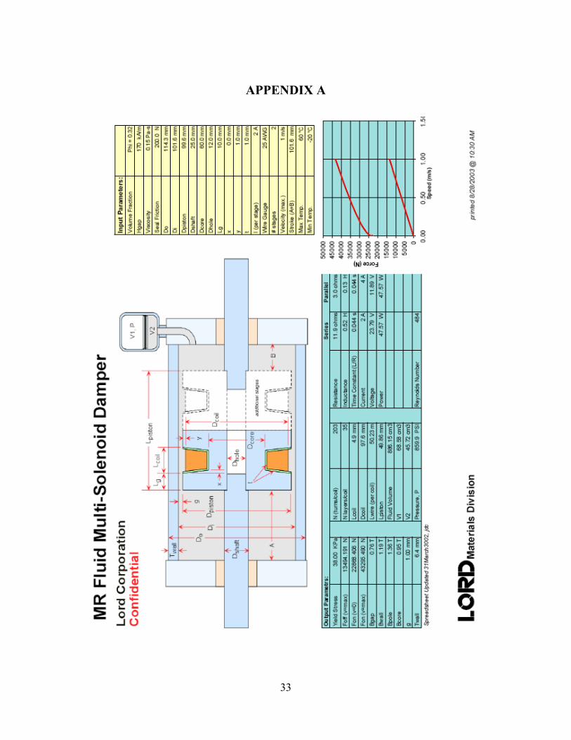
33
APPENDIX A

34
APPENDIX B
MTS - VCCS Current Test Protocol
Testing Input Signal Generation After the damper was fabricated and assembled, a series of performance tests was
conducted. The purpose of these tests was to gather sufficient data to determine the
operational capabilities of the damper and to create a fuzzy inference system that can be
used in numerical simulations used to develop the controller. A summary of these tests is
given in Table B1. Ideally, data collected during these tests should provide a sufficient
number of input and output sets such that the entire operational range of displacement,
velocity, and voltage applied to the MR damper are observed.
Based on previous experience with fuzzy modeling of MR dampers, both
deterministic and stochastic displacement and current levels were used in the tests. Each
signal was generated with a variety of frequency content. In this investigation, a
sinusoidal signal and a zero-mean Gaussian noise signal with a standard deviation given
by σ = 0.01 were generated for the specified displacement of the piston. Recall from
earlier discussion that the maximum permissible stroke of the damper is ±50.8 mm (±2
in.) about its center position. However, the peak stroke of the damper during laboratory
testing was limited to 45 mm (1.77 in.) to avoid damage to the damper during testing. In
addition to the amplitude, the damper is expected to encounter frequencies in the range of
0-1.0 Hz during in-service operation. However, the peak frequency of the damper during
testing was extended to 2.9 Hz. All displacement data were generated in Matlab with a
time step of 0.001 sec. Each test was conducted for a period of 20 sec; therefore, 10,000
data points were generated for each displacement signal.
The voltage signal sent to the MR damper during laboratory tests was created to
represent the three operating conditions: (1) passive-off, which occurs when no current is
sent to the damper; (2) passive-on, which occurs when a maximum constant current is
sent to the damper; and (3) semi-active, which occurs when a continuously varying
voltage signal is sent to the damper. Table B1 outlines thirty-four tests that were
conducted on the MR damper in a uniaxial MTS machine.

35
Table B1. Summary of Performance Test Experiments for MR Damper.
File Number Displace Type
Stroke (m)
Voltage (V)
Frequency (Hz)
Approximation Duration (sec)
1 Sinusoidal ±0.015 0.0 0.3 20.00 2 Sinusoidal ±0.020 0.0 0.3 20.00 3 Sinusoidal ±0.025 0.0 0.3 20.00 4 Sinusoidal ±0.030 0.0 0.3 20.00 5 Sinusoidal ±0.035 0.0 0.3 20.00 6 Sinusoidal ±0.040 0.0 0.3 20.00 7 Sinusoidal ±0.045 0.0 0.3 20.00 8 Sinusoidal ±0.020 0.0 0.3 20.00 9 Sinusoidal ±0.020 0.2 0.3 20.00
10 Sinusoidal ±0.020 0.4 0.3 20.00 11 Sinusoidal ±0.020 0.6 0.3 20.00 12 Sinusoidal ±0.020 0.8 0.3 20.00 13 Sinusoidal ±0.020 1.0 0.3 20.00 14 Sinusoidal ±0.020 1.2 0.3 20.00 15 Sinusoidal ±0.020 0.0 0.3 20.00 16 Sinusoidal ±0.020 0.0 0.7 20.00 17 Sinusoidal ±0.020 0.0 1.1 20.00 18 Sinusoidal ±0.020 0.0 1.5 20.00 19 Sinusoidal ±0.020 0.0 1.9 20.00 20 Sinusoidal ±0.020 0.0 2.4 20.00 21 Sinusoidal ±0.020 0.0 2.9 20.00 22 Random ±0.02~0.045 0.0 0.3 40.00 23 Random ±0.02~0.045 0.2 0.3 40.00 24 Random ±0.02 0~1.2 0.3 40.00 25 Random ±0.02 0.0 0.3~2.9 40.00
Para
met
er S
tudy
26 Random ±0.02 0.2 0.3~2.9 40.00 27 Random ±0.02~0.045 0.0 0.3~2.9 40.00 28 Random ±0.02~0.045 0.2 0.3~2.9 40.00 29 Random ±0.02~0.045 0.4 0.3~2.9 40.00 30 Random ±0.02~0.045 0.6 0.3~2.9 40.00 31 Random ±0.02~0.045 0.8 0.3~2.9 40.00 32 Random ±0.02~0.045 1.0 0.3~2.9 40.00 33 Random ±0.02~0.045 1.2 0.3~2.9 40.00
Mod
elin
g
34 Random ±0.02~0.045 0~1.2 0.3~2.9 40.00