manual motor starters handbook - abb · pdf filemanual motor starters protect the motor and...
TRANSCRIPT

Manual motor startersHandbook

2 2CDC131060M0201 2CDC131060B0201 3
Foreword
ABB offers a wide range of Manual Motor Starters (MMS), and we realize that, with all the Standards, Rules, Listings and Codes, the What, When, Where, Why and How of MMSs can get complicated.
The following information is provided to aid in the proper use of ABB manual motor starters and all their capabilities.
This handbook is written with the aim of being a general guide for people working with manual motor starter applications, but also for those who are simply interested in learning more about the product.
The book is neither a complete technical guide nor a manual for all types of ABB manual motor starters that may exist on the market. It is a complement to the catalogue, data sheets and brochures we have for our products and will give a general overview of what to consider when working with manual motor starters.
More information on manual motor starters as well as other ABB products is available at www.abb.com/lowvoltage.
All the information provided in this book is only general and each individual application must be handled as a specific case. Be sure to always follow all national and local installation regulation/codes for your specific application.
ABB will not take any responsibility for any type of faults or damage that occur due to the use of this handbook.

2 2CDC131060M0201 2CDC131060B0201 3
Content
Squirrel cage motors 5
Introduction 6
Types of motor starters 6
Basic functions 8
Function 8
Release (tripping element) 9
Overload protection 9
Short-circuit protection 9
Trip class (CLASS) 10
Time-current characteristic
(tripping characteristic) 11
Terms and ratings 12
Rated operational voltage (Ue) 12
Rated short-circuit making capacity (Icm) 12
Rated short-circuit breaking capacity 12
Rated ultimate short-circuit breaking
capacity (Icu) acc. to IEC/EN 60947-2 12
Rated service short-circuit breaking
capacity (Ics) acc. to IEC/EN 60947-2 12
Selectivity categories 13
Rated short-time withstand current (Icw) 13
Ambient air temperature compensation 13
Trip-free mechanism 14
Phase loss sensitivity 14
Functions and applications 15
Test function 15
Supply disconnecting device with
isolation function 15
Frequencies dependency 15
Application in IT-Systems 16
Switching of DC 16
Operating conditions 16
Ambient air temperature / derating 16
Restarting 16
Periodic duty 17
Installation and commissioning 18
Mounting 18
Motor Current setting procedure 18
Minimum distances 18
Mounting position 18

4 2CDC131060M0201 2CDC131060B0201 5
The greatest risk for electrical engines, such as motors or pumps, is overheating. Abnormal temperature rises can be caused by overload, electrical faults, cooling problems or improper operating parameters or operation conditions. This differentiates motors and pumps from other loads, such as heating resistors and lamps.
Examples of such overloads are:
Overloads caused by over current – Locked rotor, – Long starting or braking time, – Change of friction ratio of the operated engine – Non-permissible intermittent operation – Long-term overload in continuous operation – Undervoltage
Supply problems, which could causes unsymmetrical over-currents – Earth fault – Phase loss – Phase unbalance on the supply side – Interwinding or interturn fault within the motor
Cooling problems – Reduced convection current due to dust and dirt – Low air density due to incorrect installation altitude – Environmental parameters

4 2CDC131060M0201 2CDC131060B0201 5
The squirrel cage motor is the most common type of motor on the market. It is relatively cheap and maintenance costs are usually low. There are many different manufacturers represented on the market, selling at various prices. Not all motors have the same performance and quality as, for example, motors from ABB.
The starting current of motors is a characteristic of the motor. The starting time is a function of load torque, inertia and motor torque and is influenced by the motor technology. As the starting current (6-8 x Ie) is always a lot higher than the rated operational current Ie, an excessively long starting or braking period will cause an overload (temperature rise) in the motor. This could cause electromechanical stresses or damage the motor’s isolation.
The lifetime of an electrical engine is linked to the temperature stress. As a rough guide, the lifetime of the winding isolation reduces by half each time the temperature exceeds 10° C. However, even slight temperature increases will decrease the life time of an electrical engine significantly.
Squirrel cage motors

6 2CDC131060M0201 2CDC131060B0201 7
Types of motor startersA motor starter needs to have the following features:
– Short-circuit protection – Thermal protection – Switching capability
To ensure suitable short-circuit protection, the correct short-circuit protective device has to be selected. Based on the motor parameters and voltage, either a fuse, a circuit breaker or a manual motor starter has to be used.
To ensure thermal protection of the motor, a suitable device needs to be selected based on the motor current and the starting type. Thermal protective devices are overload relays and electronic, bi-metal or manual motor starters.
For the switching of the motor, which occurs when starting and accelerating to nor-mal speed, a contactor, manual motor starter or softstarter is used.
The ABB manual motor starters include a wide range of products providing highly efficient motor protection for motors of up to 100 A. The short-circuit breaking ca-pacity of these devices can reach up to 100 kA, depending on the MMS type used and on the operating voltage, without the need for any special upstream protection. The MMS device types have been divided into four frame sizes to ease selection, coordination and installation in different applications
– MS116 ranges up to 32 A with a width of only 45mm. – MS132 ranges up to 32 A with a width of only 45mm. Available with UL Type E + F.
– MS450 ranges up to 50 A. This provides overload protection in trip class 10. – MS49x ranges up to 100 A and is our largest MMS. It is available in three model
ranges with different interrupting capacities and trip class 10 overload protection.
Introduction
6 2CDC131060M0201 2CDC131060B0201 7
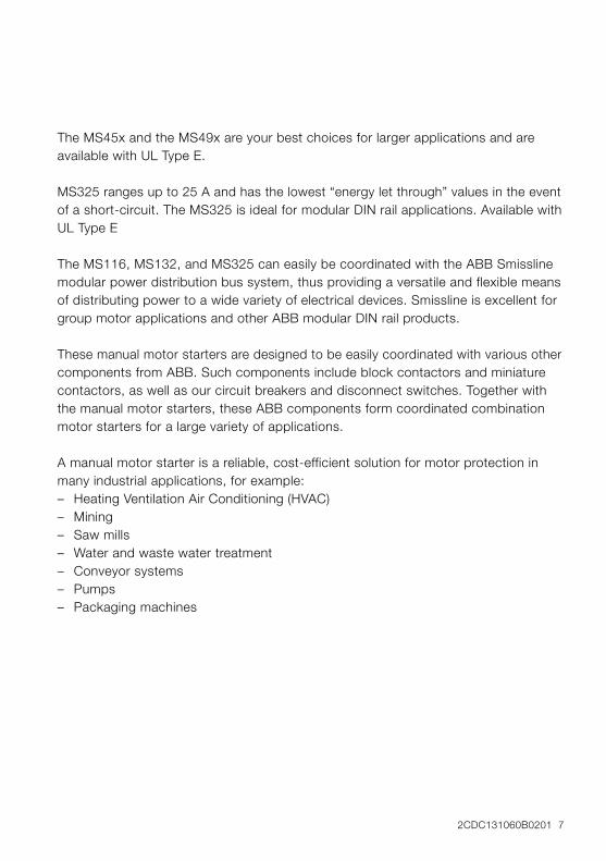
The MS45x and the MS49x are your best choices for larger applications and are available with UL Type E.
MS325 ranges up to 25 A and has the lowest “energy let through” values in the event of a short-circuit. The MS325 is ideal for modular DIN rail applications. Available with UL Type E
The MS116, MS132, and MS325 can easily be coordinated with the ABB Smissline modular power distribution bus system, thus providing a versatile and flexible means of distributing power to a wide variety of electrical devices. Smissline is excellent for group motor applications and other ABB modular DIN rail products.
These manual motor starters are designed to be easily coordinated with various other components from ABB. Such components include block contactors and miniature contactors, as well as our circuit breakers and disconnect switches. Together with the manual motor starters, these ABB components form coordinated combination motor starters for a large variety of applications.
A manual motor starter is a reliable, cost-efficient solution for motor protection in many industrial applications, for example: – Heating Ventilation Air Conditioning (HVAC) – Mining – Saw mills – Water and waste water treatment – Conveyor systems – Pumps – Packaging machines

8 2CDC131060M0201 2CDC131060B0201 9
FunctionManual motor starters protect the motor and the installation against short-circuits and overload. They are three-pole electro-mechanical protection devices with a release for overload protection and short-circuit protection. Furthermore, they provide a disconnect function for safe isolation of the installation and the power supply and can be used for switching loads manually.
Manual motor starters meet the requirements in accordance with IEC/EN 60947-2, IEC/EN 60947-4-1 and UL 60947-4-1A (previously UL 508). The protection function is realized with the following sub-functions: – Overload protection – Short-circuit protection – Phase loss sensitivity
The manual motor starter disconnects all phases from the line when an overload or short-circuit occurs. The power to the protected motor is thus switched off directly.
In addition, the ABB manual motor starters increase the reliability of applications due to their quick reaction time, switching off the motor within milliseconds of a short-circuit occurring, which prevents motor damage.
The term “manual motor starter” is not mentioned in the IEC standards. Other terms are motor-protective circuit-breaker or simply circuit breaker.
Basic functions

8 2CDC131060M0201 2CDC131060B0201 9
Release (tripping element)Manual motor starters are equipped with the following releases: – Inverse time-delay over-current release for overload protection – Instantaneous short-circuit releases for short-circuit protection
The inverse time-delay over-current release is adjustable for the motor current of the feeder.
Manual motor starters magnetic only are equipped with an instantaneous short-circuit release only. They are always used in combination with a contactor and an overload
relay, as these devices are not able to provide suitable motor overload protection.
In the event of motor overload, the overload relay trips and the contactor switches OFF. However, the manual motor starter magnetic only stays switched ON. The manual motor starter magnetic only trips only in the event of a short-circuit and clears the fault. Consequently, this starter allows differentiation between overload and short-circuit by means of separate signaling.
Overload protectionThe actual motor current of the motor to be protected has to be adjusted on the setting scale. The manual motor starters have a setting scale in amperes, which allows the device to be adjusted directly without any additional calculation. In compliance with international and national standards, the setting current is the rated current of the motor and not the tripping current (no tripping at 1.05 x I, tripping at 1.2 x I; I = setting current).
Short-circuit protectionThe factory sets the instantaneous short-circuit release to a fixed multiple value of the rated operational current, thus providing a direct motor start with reliable motor protection.
10 2CDC131060M0201 2CDC131060B0201 11
MSx Tripping characteristic
Multiple of the rated current
Electro-magnetictripping
Thermaltripping
Three-pole
Two-pole
Trip
pin
g t
ime
seco
nds
min
utes
100
50
20
10
5
2
50
20
10
5
2
1
0.5
0.2
0.1
0.05
0.01
0.005
0.002
0.001
0.02
[A]1 1.5 2 3 4 6 8 10 15 20 30 40 60 80
MOx Tripping characteristic
Multiple of the rated current
Electro-magnetictripping
Trip
pin
g t
ime
seco
nds
min
utes
100
50
20
10
5
2
50
20
10
5
2
1
0.5
0.2
0.1
0.05
0.01
0.005
0.002
0.001
0.02
[A]1 1.5 2 3 4 6 8 10 15 20 30 40 60 80
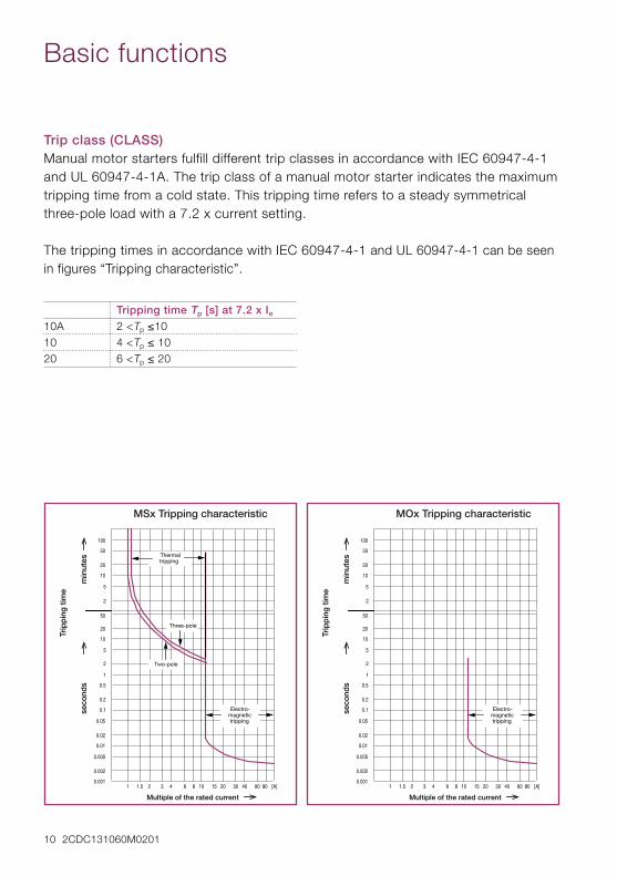
Tripping time Tp [s] at 7.2 x Ie
10A 2 <Tp ≤1010 4 <Tp ≤ 1020 6 <Tp ≤ 20
Trip class (CLASS)Manual motor starters fulfill different trip classes in accordance with IEC 60947-4-1 and UL 60947-4-1A. The trip class of a manual motor starter indicates the maximum tripping time from a cold state. This tripping time refers to a steady symmetrical three-pole load with a 7.2 x current setting.
The tripping times in accordance with IEC 60947-4-1 and UL 60947-4-1 can be seen in figures “Tripping characteristic”.
Basic functions

10 2CDC131060M0201 2CDC131060B0201 11
Time-current characteristic (tripping characteristic) On the time-current characteristic curve, the tripping characteristic of the inverse time-delay thermal over-current release applies for direct current (DC) and alternating current (AC) with frequencies of 50/60 Hz.
For three-pole loads and currents of between 3 - 8 times the current setting, the tolerance of the tripping time is ±20 %.
The tripping characteristic of the instantaneous short-circuit releases is based on the rated operational current Ie, which, in the case of the manual motor starter, is the same as the upper value of the setting range. Lower current settings result in a higher multiple for the tripping current of the instantaneous short-circuit releases. The tripping characteristic curves are valid for the cold state; in a warm state, the tripping times of the inverse time-delay thermal over-current release have a higher spread and can decrease to around 25 %.
LinkThe time-current characteristic can be accessed in the download center (http://www.abb.com/lowvoltage or http://www.abb.com/abblibrary/DownloadCenter).

12 2CDC131060M0201 2CDC131060B0201 13
Rated operational voltage (Ue)The rated operational voltage of a manual motor starter is a value of phase-to phase voltage which determines the possible application of the manual motor starter, this needs to be considered in combination with a rated operational current.
Rated short-circuit making capacity (Icm)The rated short-circuit making capacity (current, voltage) is the short-circuit current that a manual motor starter can make at rated operational voltage, rated frequency and a fixed power factor. It is expressed as the maximum prospective peak current.
Rated short-circuit breaking capacityThe rated short-circuit breaking capacity (current, voltage) is the short-circuit current that a manual motor starter can break at rated operational voltage, rated frequency and a fixed power factor. It is expressed as the maximum prospective peak current. It is expressed as the rated ultimate short-circuit breaking capacity or rated service short-circuit breaking capacity.
Rated ultimate short-circuit breaking capacity (Icu) acc. to IEC/EN 60947-2This is the maximum short-circuit breaking capacity (current, voltage) that manual motor starter can interrupt without being damaged. After the short-circuit interruption, in the event of an overload the manual motor starter is able to trip with increased tolerances.
Rated service short-circuit breaking capacity (Ics) acc. to IEC/EN 60947-2This is the short-circuit breaking capacity (current, voltage) that manual motor starters can repeatedly interrupt without being damaged.
After the short-circuit interruption, the manual motor starter is able to carry the rated operational current and to trip in the case of an overload.
Terms and ratings

12 2CDC131060M0201 2CDC131060B0201 13
Ι Overload as a multiple of the rated currentϑ Ambient air temperature
IEC Limit values acc. IEC60947-4-1
-5 0 20 40
1.01.051.1
1.2
1.3
ϑ
Ι
[°C]
[A]IEC
Selectivity categoriesSelectivity describes the behavior of two protective devices connected in series under short-circuit conditions. In the event of selectivity trips the protective device close to the fault that fast, that the upstream protective device don’t trip. The IEC 60947 defines two different categories of low-voltage circuit breakers:
– A = Circuit-breakers not specifically intended for selectivity under short-circuit conditions
– B = Circuit-breakers specifically intended for selectivity under short-circuit conditions
ABB manual motor starters are all selectivity category A.
Rated short-time withstand current (Icw)The rated short-time withstand current of an item of equipment is the value of the short-time withstand current , which the equipment can carry without damage under the test conditions specified in the relevant product standard. The equipment as-signs this value.
Ambient air temperature compensationAmbient air temperature compensation is realized by a second bimetal, which coun-teracts the bimetals of the inverse time-delay thermal over-current release. The second bimetal is not heated by motor current, but bends only under the influence of the ambient air temperature. As a result, the influence of the ambient air temperature on the tripping characteristics of the manual motor starter is automatically compensated.
The ambient air temperature compensation is defined in IEC/EN 609471-4-1 within a temperature range from –5 to +40 °C.
14 2CDC131060M0201 2CDC131060B0201 15
Trip-free mechanismAs required by IEC/EN 60947-1, the manual motor starter features a trip-free mech-anism. This means that the manual motor starter trips even if the handle is locked in the “ON” position or held by hand. According to IEC/EN 60204, a supply discon-necting device also requires a trip-free mechanism.
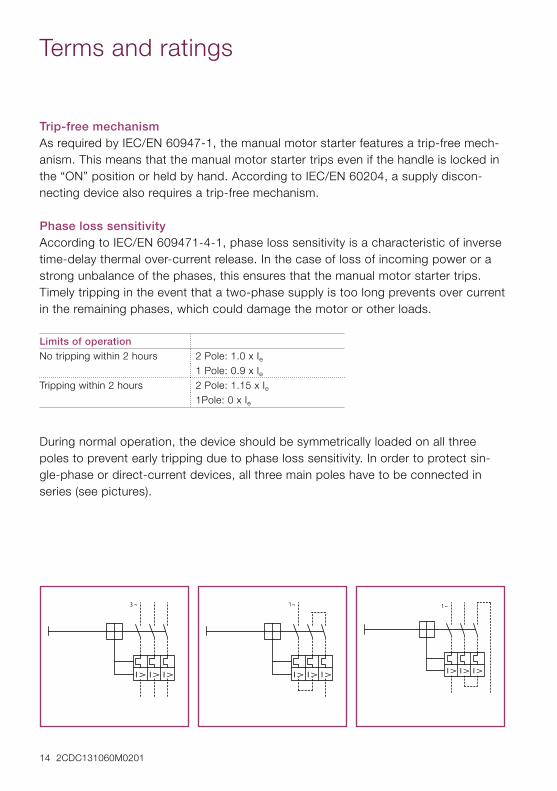
Phase loss sensitivity According to IEC/EN 609471-4-1, phase loss sensitivity is a characteristic of inverse time-delay thermal over-current release. In the case of loss of incoming power or a strong unbalance of the phases, this ensures that the manual motor starter trips. Timely tripping in the event that a two-phase supply is too long prevents over current in the remaining phases, which could damage the motor or other loads.
Limits of operationNo tripping within 2 hours 2 Pole: 1.0 x Ie
1 Pole: 0.9 x IeTripping within 2 hours 2 Pole: 1.15 x Ie
1Pole: 0 x Ie
During normal operation, the device should be symmetrically loaded on all three poles to prevent early tripping due to phase loss sensitivity. In order to protect sin-gle-phase or direct-current devices, all three main poles have to be connected in series (see pictures).
Terms and ratings

14 2CDC131060M0201 2CDC131060B0201 15
Test functionYou can check the proper mechanical function of the active manual motor starters using the TEST function. Actuating the test release with the help of a screwdriver simulates a tripping of the manual motor starter. This function is useful during commissioning to check the wiring, including mounted accessories.
Supply disconnecting device with isolation functionThe manual motor starter fulfills the characteristics of a circuit-breaker suitable for isolation in accordance with IEC 60947-2, meaning the manual motor starter can be used as a supply disconnecting (isolating) device in accordance with IEC/EN 60204.
The products are marked with the isolation function symbol in accordance with IEC 60617-7, reference 07-01-03:
Frequencies dependency The time-current characteristic curves of the instantaneous short-circuit releases are valid for frequencies from 50 Hz to 60 Hz. Frequencies other than 50/60 Hz will have an impact on the instantaneous short-circuit releases. In the range of 45 ... 66 Hz, the operating values of the instantaneous short-circuit release are within the given tolerance. With increasing frequencies above 60 Hz or DC, the operating value of the instantaneous short-circuit release increases. For frequencies below 50 Hz, the op-erating value of the magnetic release decreases.
The tripping characteristic of the inverse time-delay thermal over-current release is valid for direct current (DC) and alternating current (AC, with frequencies from 0 Hz to 400 Hz). For all operating values of the releases, a tolerance of 20 % needs to be considered (see time-current characteristic).
DC 10 Hz 45 … 66 Hz 100 HzCorrection factors 1.1 0.9 1 1.1
Functions and applications

16 2CDC131060M0201 2CDC131060B0201 17
Application in IT-SystemsThe manual motor starters are suitable for IT systems in accordance with IEC/EN 60947-2 Annex H. In the case of a 3-pole short-circuit, they behave as in other sys-tems. Thus, the same short-circuit breaking capacity Icu and Ics applies.
Switching of DCThe manual motor starters are also suitable for switching direct current (DC). However, the rated operational voltage for DC and short-circuit breaking capacity have to be considered. Special requirements for main pole wiring also need to be considered.
Operating conditionsManual motor starters are suitable for use in any climate. They are intended for use in enclosed environments in which no severe operating conditions (such as dust, caustic vapors or hazardous gases) prevail. When installed in dusty and damp areas, suitable enclosures must be provided.
Ambient air temperature / deratingThe permissible ambient air temperatures, the maximum switching capacities, the tripping currents and other limiting conditions can be found in the technical specifi-cations and tripping characteristics.
The manual motor starters are temperature compensated in accordance with IEC/EN 60947-4-1. Depending on the device, the temperature range is between -25 °C and +55 °C or -25 °C and +60 °C. For temperatures between +55/60 °C and +70 °C, the upper set value of the adjustment range has to be reduced by a certain factors. Please contact your ABB to get more information.
RestartingAfter tripping, the inverse time-delay thermal over-current release needs to cool down before the manual motor starter can be reset.
Functions and applications

16 2CDC131060M0201 2CDC131060B0201 17
Periodic duty Manual motor starters cannot be operated at any arbitrary operating frequency in order to avoid tripping. Applications involving up to 15 starts per hour are acceptable. Higher operating frequencies are permitted if the duty ratio and the motor starting time are allowed for and if the motor‘s making current does not appreciably exceed six times the rated operating current. Please refer to the adjacent diagram for guide-line values for the permitted switching frequency.
We recommend using a combination of a manual motor starter and thermistor protection relays for higher switching frequencies and alternating loading, e.g. for frequent starting and braking.
140
120
0
20
40
60
80
100
0 20 40 60 80 100 (%)
t = 1 s
a
t = 1.5 s
a
t = 3 sa
t = 5 sa
t = 0.5 sa
duty ratio
switc
hing
freq
uenc
y
(Op/h)

18 2CDC131060M0201 2CDC131060B0201 19
Mounting – Fixed on a 35 mm top hat rail according to DIN EN 60715 – Screw fixing on wall/panel. Manual motor starters can be fastened to the wall/panel
using screws. MS116/MS132 manual motor starters require the accessory.
Single installation: there is no directly attached contactor and there is a minimum gap of 9 mm to the left and to the right.
Group installation: the contactor is mounted directly or the gap to the left or the right is less than 9 mm.
The manual motor starter can be supplied either from the bottom or from the top (for non UL applications).
Installation and commissioning
Pos. 1
Pos. 2
Pos. 4
Pos. 1 ± 30°
- 30°+ 30°
Pos. 5 Pos. 6
Pos. 3
Motor current setting procedureSet the current on the scale of the manual motor starter current setting with the help of a screw-driver.
Minimum distancesDuring installation, please ensure that the distance to grounded parts and live parts, as well distances to cable channels consisting of insulation material, adheres to IEC 60947-2.
Mounting positionMounting positions 1…6 are permitted for manual motor starters.
Mounting position

18 2CDC131060M0201 2CDC131060B0201 19

Contact us
Ord
er N
um
ber
2C
DC
131
060
M02
01
Prin
ted
in G
erm
any
(09/
13)
Note:We reserve the right to make technical changes or modify the contents of this document without prior notice. With regard to purchase orders, the agreed particulars shall prevail. ABB AG does not accept any responsibility whatsoever for potential errors or possible lack of information in this document.
We reserve all rights in this document and in the subject matter and illustrations contained therein. Any reproduction, disclosure to third parties or utilization of its contents – in whole or in parts – is forbidden without prior written consent of ABB AG.
Copyright © 2013 ABB All rights reserved
ABB STOTZ-KONTAKT GmbHEppelheimer Straße 8269123 Heidelberg, GermanyPhone: +49 (0) 6221 701-0Fax: +49 (0) 6221 701-1325E-Mail: [email protected] www.abb.com
You can find the address of your local sales organization on the ABB home pagehttp://www.abb.com/contacts -> Low-voltage products