max air.pdf
TRANSCRIPT

6
UT SERIES PNEUMATIC ROTARY ACTUATORS
www.max-airtechnology.com • Toll Free 1.888.842.9998 • Fax 1.866.842.3144

62 THE BEST WAY TO AUTOMATE YOUR PROCESS
www.max-airtechnology.com 6
FEATURES
Introducing the NEW MT SERIES Actuators! The MT series offers a flangeless design which makes automation easy. The MT series also offers two ISO bolt circles as a standard which eliminates the need for the flange. Ask about the new
Stainless Actuators!
COMPACT DESIGNThe MAX-AIR rack & pinion pneumatic actuator produces linear torque output in a compact design utilizing the same body and end caps for double acting and spring return units.
NAMUR MOUNTINGNAMUR VDI/VDE 3845 and ISO 5211 dimensions on all sizes. No special blocks are required to mount solenoid valves, limit switches or positioners.
DEGREE OF TRAVELThe standard angle of rotation is 90°*. Additional travel rotations of 120°, 135°, 150° and 180° are available. For sizes UT16 through UT66, Max-Air features dual travel stops that provide for ±10° stroke rotation on both the opening and closing phases—that’s 110° of travel in a standard 90° actuator!
MULTIPLE OUTPUT SHAFTSThe female pinion drive is standard with a double square output drive, and optional with a double-D drive, keyed drive and designs to meet your specific requirements.
HIGH CYCLE BEARINGSShaft bearings isolate the pinion gear from the housing and support the shaft for high cycle applications. Many competitive manufacturers do not provide this critical feature.
RUGGED TOOTH DESIGNThe pinion teeth are engaged the full length and stroke of the piston. The pinion height allows manual override without disturbing the indicated positions.
HIGH VISIBILITY POSITION INDICATIONExternal open/close indicator as standard, available for all the rotations.
HIGH CYCLE LIFE WEAR PADSPistons incorporate double wear pads to separate the rack from the actuator wall and serve as both guide and wear bearings.
PRE-LOADED SPRING CARTRIDGES FOR SAFETYEpoxy coated special steel springs are pre-loaded with non-metallic materials. The stainless steel end cap fasteners are extra long to allow for spring relaxation. All parts are corrosion resistant.
ALTERNATIVE OPERATING MEDIAAir pressure operation from 2 to 10 Bar (40–150 PSI). Water, nitrogen and compatible hydraulic fluids may also be used to power the actuator.
STAINLESS STEEL FASTENERSAll external fasteners are corrosion resistant stainless steely.
HONED BORE FOR HIGH CYCLE-LIFEExtruded aluminum body is internally machined and lapped to exact specifications. Honing prevents dry spots from forming within the actuator bore and therefore eliminates premature seal failure —a critical aspect to long cycle life. All internal and external surfaces are hard anodized for corrosion resistance, with all units permanently lubricated at the factory with non-silicone grease.
TRACEABILITYAll units are externally stamped with a progressive traceable serial number.
QUALITY ASSURANCE100% of all units are factory pressure and leak tested, and individually boxed for shipment.
BEST WARRANTY IN THE INDUSTRYMax-Air products are covered by the best warranty in the industry. Contact your representative for more details.
ACCESSORIESMax-Air offers a wide range of adapters for many different types of valves, including BFV, BALL and PLUG types.
Please call for details.*UT71 and UT76 offer 5° stroke adjustment on the opening phase of the actuator.
663THE BEST WAY TO AUTOMATE YOUR PROCESS
www.max-airtechnology.com
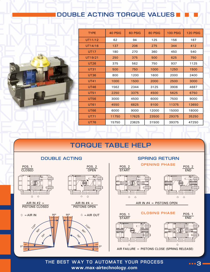
DOUBLE ACTING TORQUE VALUES
TYPE 40 PSIG 60 PSIG 80 PSIG 100 PSIG 120 PSIG
UT11/12 62 94 125 156 187
UT14/16 137 206 275 344 412
UT17 180 270 360 450 540
UT19/21 250 375 500 625 750
UT26 375 562 750 937 1125
UT31 500 750 1000 1250 1500
UT36 800 1200 1600 2000 2400
UT41 1000 1500 2000 2500 3000
UT46 1562 2344 3125 3906 4687
UT51 2250 3375 4500 5625 6750
UT56 3000 4500 6000 7500 9000
UT61 4550 6825 9100 11375 13650
UT66 6000 9000 12000 15000 18000
UT71 11750 17625 23500 29375 35250
UT76 15750 23625 31500 39375 47250
TORQUE TABLE HELP
DOUBLE ACTING SPRING RETURN
POS. 1CLOSED
POS. 2OPEN
POS. 2START
POS. 2END
POS. 1START
POS. 1END
AIR IN #2 =PISTONS CLOSED
AIR IN #4 =PISTONS OPEN
=AIR IN =AIR OUT
AIR IN #4 = PISTONS OPEN
AIR FAILURE = PISTONS CLOSE (SPRING RELEASE)
O P E N I N G P H A S E
C L O S I N G P H A S E
64 THE BEST WAY TO AUTOMATE YOUR PROCESS
www.max-airtechnology.com 6
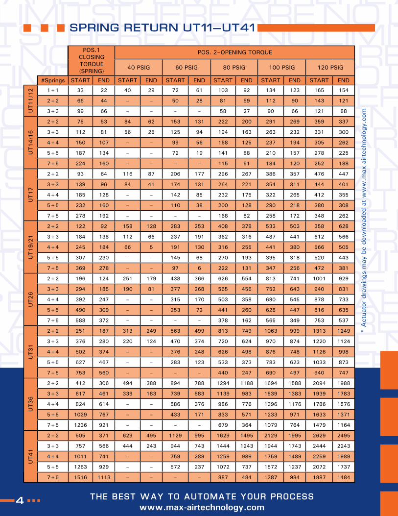
POS.1CLOSING TORQUE (SPRING)
POS. 2–OPENING TORQUE
40 PSIG 60 PSIG 80 PSIG 100 PSIG 120 PSIG
#Springs START END START END START END START END START END START END
UT11/1
2 1+1 33 22 40 29 72 61 103 92 134 123 165 154
2+2 66 44 – – 50 28 81 59 112 90 143 121
3+3 99 66 – – – – 58 27 90 66 121 88
UT14/1
6
2+2 75 53 84 62 153 131 222 200 291 269 359 337
3+3 112 81 56 25 125 94 194 163 263 232 331 300
4+4 150 107 – – 99 56 168 125 237 194 305 262
5+5 187 134 – – 72 19 141 88 210 157 278 225
7+5 224 160 – – – – 115 51 184 120 252 188
UT17
2+2 93 64 116 87 206 177 296 267 386 357 476 447
3+3 139 96 84 41 174 131 264 221 354 311 444 401
4+4 185 128 – – 142 85 232 175 322 265 412 355
5+5 232 160 – – 110 38 200 128 290 218 380 308
7+5 278 192 – – – – 168 82 258 172 348 262
UT19/2
1
2+2 122 92 158 128 283 253 408 378 533 503 358 628
3+3 184 138 112 66 237 191 362 316 487 441 612 566
4+4 245 184 66 5 191 130 316 255 441 380 566 505
5+5 307 230 – – 145 68 270 193 395 318 520 443
7+5 369 278 – – 97 6 222 131 347 256 472 381
UT26
2+2 196 124 251 179 438 366 626 554 813 741 1001 929
3+3 294 185 190 81 377 268 565 456 752 643 940 831
4+4 392 247 – – 315 170 503 358 690 545 878 733
5+5 490 309 – – 253 72 441 260 628 447 816 635
7+5 588 372 – – – – 378 162 565 349 753 537
UT31
2+2 251 187 313 249 563 499 813 749 1063 999 1313 1249
3+3 376 280 220 124 470 374 720 624 970 874 1220 1124
4+4 502 374 – – 376 248 626 498 876 748 1126 998
5+5 627 467 – – 283 123 533 373 783 623 1033 873
7+5 753 560 – – – – 440 247 690 497 940 747
UT36
2+2 412 306 494 388 894 788 1294 1188 1694 1588 2094 1988
3+3 617 461 339 183 739 583 1139 983 1539 1383 1939 1783
4+4 824 614 – – 586 376 986 776 1396 1176 1786 1576
5+5 1029 767 – – 433 171 833 571 1233 971 1633 1371
7+5 1236 921 – – – – 679 364 1079 764 1479 1164
UT41
2+2 505 371 629 495 1129 995 1629 1495 2129 1995 2629 2495
3+3 757 566 444 243 944 743 1444 1243 1944 1743 2444 2243
4+4 1011 741 – – 759 289 1259 989 1759 1489 2259 1989
5+5 1263 929 – – 572 237 1072 737 1572 1237 2072 1737
7+5 1516 1113 – – – – 887 484 1387 984 1887 1484
* A
ctua
tor
draw
ings
may
be
dow
nloa
ded
at w
ww
.max
-airt
echn
olog
y.co
m
SPRING RETURN UT11–UT41
665THE BEST WAY TO AUTOMATE YOUR PROCESS
www.max-airtechnology.com
* A
ctua
tor
draw
ings
may
be
dow
nloa
ded
at w
ww
.max
-airt
echn
olog
y.co
m
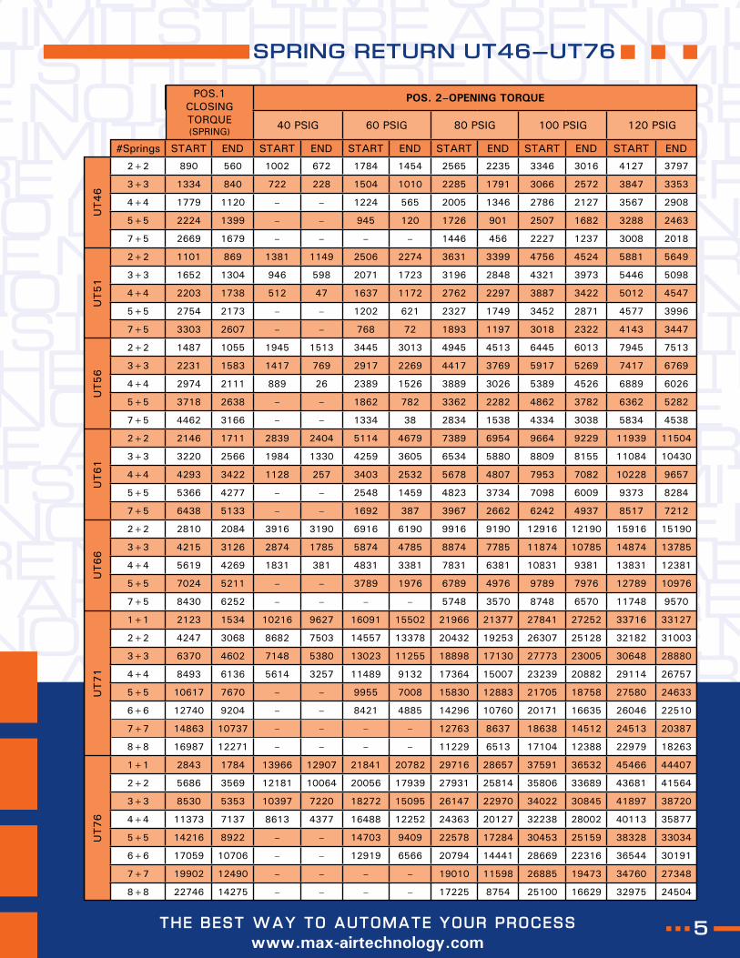
SPRING RETURN UT46–UT76
POS.1CLOSING TORQUE (SPRING)
POS. 2–OPENING TORQUE
40 PSIG 60 PSIG 80 PSIG 100 PSIG 120 PSIG
#Springs START END START END START END START END START END START END
UT46
2+2 890 560 1002 672 1784 1454 2565 2235 3346 3016 4127 3797
3+3 1334 840 722 228 1504 1010 2285 1791 3066 2572 3847 3353
4+4 1779 1120 – – 1224 565 2005 1346 2786 2127 3567 2908
5+5 2224 1399 – – 945 120 1726 901 2507 1682 3288 2463
7+5 2669 1679 – – – – 1446 456 2227 1237 3008 2018
UT51
2+2 1101 869 1381 1149 2506 2274 3631 3399 4756 4524 5881 5649
3+3 1652 1304 946 598 2071 1723 3196 2848 4321 3973 5446 5098
4+4 2203 1738 512 47 1637 1172 2762 2297 3887 3422 5012 4547
5+5 2754 2173 – – 1202 621 2327 1749 3452 2871 4577 3996
7+5 3303 2607 – – 768 72 1893 1197 3018 2322 4143 3447
UT56
2+2 1487 1055 1945 1513 3445 3013 4945 4513 6445 6013 7945 7513
3+3 2231 1583 1417 769 2917 2269 4417 3769 5917 5269 7417 6769
4+4 2974 2111 889 26 2389 1526 3889 3026 5389 4526 6889 6026
5+5 3718 2638 – – 1862 782 3362 2282 4862 3782 6362 5282
7+5 4462 3166 – – 1334 38 2834 1538 4334 3038 5834 4538
UT61
2+2 2146 1711 2839 2404 5114 4679 7389 6954 9664 9229 11939 11504
3+3 3220 2566 1984 1330 4259 3605 6534 5880 8809 8155 11084 10430
4+4 4293 3422 1128 257 3403 2532 5678 4807 7953 7082 10228 9657
5+5 5366 4277 – – 2548 1459 4823 3734 7098 6009 9373 8284
7+5 6438 5133 – – 1692 387 3967 2662 6242 4937 8517 7212
UT66
2+2 2810 2084 3916 3190 6916 6190 9916 9190 12916 12190 15916 15190
3+3 4215 3126 2874 1785 5874 4785 8874 7785 11874 10785 14874 13785
4+4 5619 4269 1831 381 4831 3381 7831 6381 10831 9381 13831 12381
5+5 7024 5211 – – 3789 1976 6789 4976 9789 7976 12789 10976
7+5 8430 6252 – – – – 5748 3570 8748 6570 11748 9570
UT71
1+1 2123 1534 10216 9627 16091 15502 21966 21377 27841 27252 33716 33127
2+2 4247 3068 8682 7503 14557 13378 20432 19253 26307 25128 32182 31003
3+3 6370 4602 7148 5380 13023 11255 18898 17130 27773 23005 30648 28880
4+4 8493 6136 5614 3257 11489 9132 17364 15007 23239 20882 29114 26757
5+5 10617 7670 – – 9955 7008 15830 12883 21705 18758 27580 24633
6+6 12740 9204 – – 8421 4885 14296 10760 20171 16635 26046 22510
7+7 14863 10737 – – – – 12763 8637 18638 14512 24513 20387
8+8 16987 12271 – – – – 11229 6513 17104 12388 22979 18263
UT76
1+1 2843 1784 13966 12907 21841 20782 29716 28657 37591 36532 45466 44407
2+2 5686 3569 12181 10064 20056 17939 27931 25814 35806 33689 43681 41564
3+3 8530 5353 10397 7220 18272 15095 26147 22970 34022 30845 41897 38720
4+4 11373 7137 8613 4377 16488 12252 24363 20127 32238 28002 40113 35877
5+5 14216 8922 – – 14703 9409 22578 17284 30453 25159 38328 33034
6+6 17059 10706 – – 12919 6566 20794 14441 28669 22316 36544 30191
7+7 19902 12490 – – – – 19010 11598 26885 19473 34760 27348
8+8 22746 14275 – – – – 17225 8754 25100 16629 32975 24504
66
www.max-airtechnology.com 6
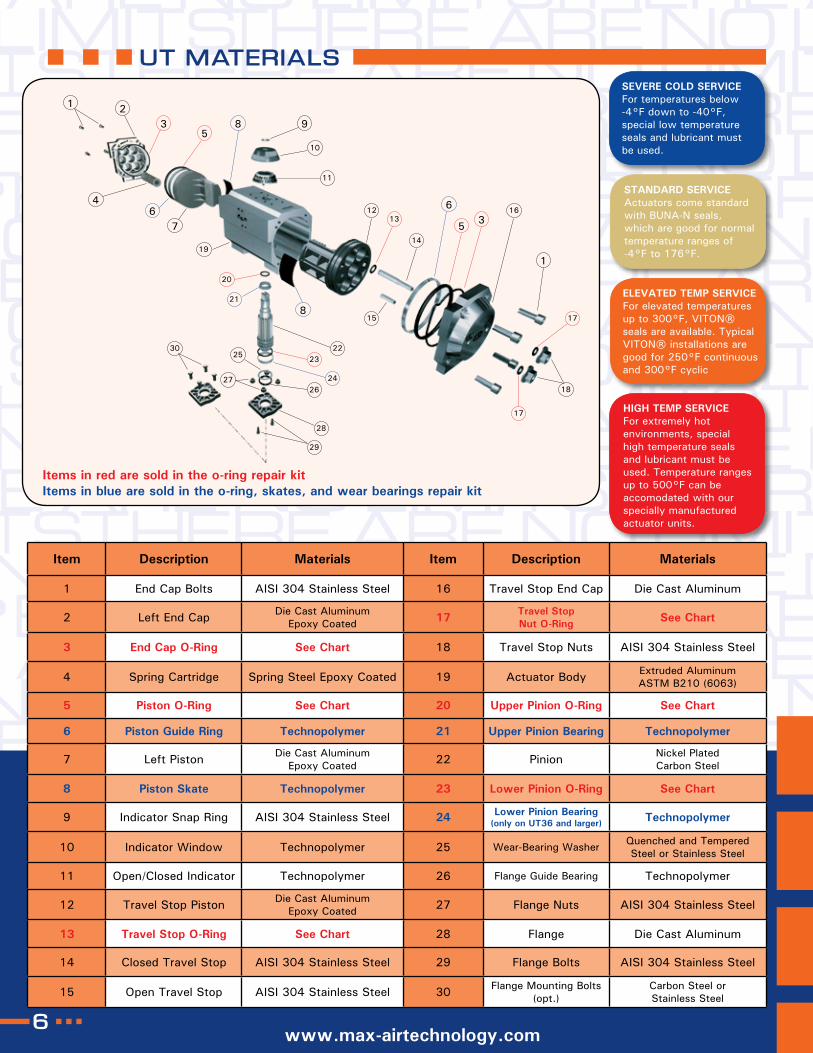
UT MATERIALS
Item Description Materials Item Description Materials
1 End Cap Bolts AISI 304 Stainless Steel 16 Travel Stop End Cap Die Cast Aluminum
2 Left End Cap Die Cast Aluminum Epoxy Coated 17 Travel Stop
Nut O-Ring See Chart
3 End Cap O-Ring See Chart 18 Travel Stop Nuts AISI 304 Stainless Steel
4 Spring Cartridge Spring Steel Epoxy Coated 19 Actuator Body Extruded Aluminum ASTM B210 (6063)
5 Piston O-Ring See Chart 20 Upper Pinion O-Ring See Chart
6 Piston Guide Ring Technopolymer 21 Upper Pinion Bearing Technopolymer
7 Left Piston Die Cast Aluminum Epoxy Coated 22 Pinion Nickel Plated
Carbon Steel
8 Piston Skate Technopolymer 23 Lower Pinion O-Ring See Chart
9 Indicator Snap Ring AISI 304 Stainless Steel 24 Lower Pinion Bearing(only on UT36 and larger) Technopolymer
10 Indicator Window Technopolymer 25 Wear-Bearing Washer Quenched and Tempered Steel or Stainless Steel
11 Open/Closed Indicator Technopolymer 26 Flange Guide Bearing Technopolymer
12 Travel Stop Piston Die Cast Aluminum Epoxy Coated 27 Flange Nuts AISI 304 Stainless Steel
13 Travel Stop O-Ring See Chart 28 Flange Die Cast Aluminum
14 Closed Travel Stop AISI 304 Stainless Steel 29 Flange Bolts AISI 304 Stainless Steel
15 Open Travel Stop AISI 304 Stainless Steel 30 Flange Mounting Bolts (opt.)
Carbon Steel or Stainless Steel
SEVERE COLD SERVICEFor temperatures below -4°F down to -40°F, special low temperature seals and lubricant must be used.
STANDARD SERVICEActuators come standard with BUNA-N seals, which are good for normal temperature ranges of -4°F to 176°F.
ELEVATED TEMP SERVICEFor elevated temperatures up to 300°F, VITON® seals are available. Typical VITON® installations are good for 250°F continuous and 300°F cyclic
HIGH TEMP SERVICEFor extremely hot environments, special high temperature seals and lubricant must be used. Temperature ranges up to 500°F can be accomodated with our specially manufactured actuator units.
Items in red are sold in the o-ring repair kitItems in blue are sold in the o-ring, skates, and wear bearings repair kit
1 23
59
10
28
1213
14
6
5 316
1
17
18
17
158
2223
2426
29
30
27
25
21
20
19
76
4
8
11
667
www.max-airtechnology.com
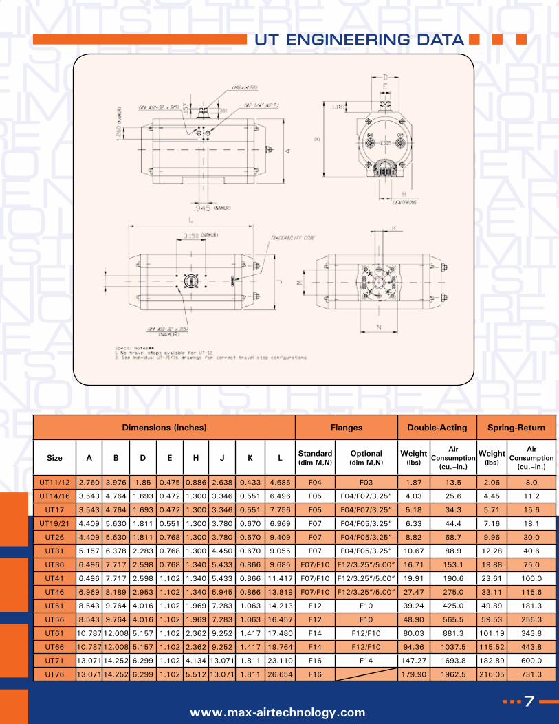
UT ENGINEERING DATA
Dimensions (inches) Flanges Double-Acting Spring-Return
Size A B D E H J K L Standard (dim M,N)
Optional (dim M,N)
Weight (lbs)
Air Consumption
(cu.–in.)
Weight (lbs)
Air Consumption
(cu.–in.)
UT11/12 2.760 3.976 1.85 0.475 0.886 2.638 0.433 4.685 F04 F03 1.87 13.5 2.06 8.0
UT14/16 3.543 4.764 1.693 0.472 1.300 3.346 0.551 6.496 F05 F04/F07/3.25” 4.03 25.6 4.45 11.2
UT17 3.543 4.764 1.693 0.472 1.300 3.346 0.551 7.756 F05 F04/F07/3.25” 5.18 34.3 5.71 15.6
UT19/21 4.409 5.630 1.811 0.551 1.300 3.780 0.670 6.969 F07 F04/F05/3.25” 6.33 44.4 7.16 18.1
UT26 4.409 5.630 1.811 0.768 1.300 3.780 0.670 9.409 F07 F04/F05/3.25” 8.82 68.7 9.96 30.0
UT31 5.157 6.378 2.283 0.768 1.300 4.450 0.670 9.055 F07 F04/F05/3.25” 10.67 88.9 12.28 40.6
UT36 6.496 7.717 2.598 0.768 1.340 5.433 0.866 9.685 F07/F10 F12/3.25”/5.00” 16.71 153.1 19.88 75.0
UT41 6.496 7.717 2.598 1.102 1.340 5.433 0.866 11.417 F07/F10 F12/3.25”/5.00” 19.91 190.6 23.61 100.0
UT46 6.969 8.189 2.953 1.102 1.340 5.945 0.866 13.819 F07/F10 F12/3.25”/5.00” 27.47 275.0 33.11 115.6
UT51 8.543 9.764 4.016 1.102 1.969 7.283 1.063 14.213 F12 F10 39.24 425.0 49.89 181.3
UT56 8.543 9.764 4.016 1.102 1.969 7.283 1.063 16.457 F12 F10 48.90 565.5 59.53 256.3
UT61 10.787 12.008 5.157 1.102 2.362 9.252 1.417 17.480 F14 F12/F10 80.03 881.3 101.19 343.8
UT66 10.787 12.008 5.157 1.102 2.362 9.252 1.417 19.764 F14 F12/F10 94.36 1037.5 115.52 443.8
UT71 13.071 14.252 6.299 1.102 4.134 13.071 1.811 23.110 F16 F14 147.27 1693.8 182.89 600.0
UT76 13.071 14.252 6.299 1.102 5.512 13.071 1.811 26.654 F16 179.90 1962.5 216.05 731.3
6
Your nearest Max-Air dealer can be found at:
Did you know that we provide the following services?
n 2D and 3D CAD Assembly Drawingsn Trained Technical Support Servicesn On–site Commissioning Servicesn Engineering System Design Services
The Best Way to Automate Your Process
rev. 5/2011