maximizing performance using mcs 251 microcontroller
TRANSCRIPT

EAPPLICATION
NOTE
AP-709
Maximizing Performance usingMCS® 251 Microcontroller
-Programming the 8xC251SB
Order Number:272671-001
SEONG FOOK TSEN
TECHNICAL MARKETING ENGINEER
EIGHT BIT MICROCONTROLLERS
February 1995

AP-709 E
2
Intel Corporation makes no warranty for the use of its products and assumes no responsibility for any errors which may appearin this document nor does it make a commitment to update the information contained herein.
Intel retains the right to make changes to these specifications at any time, without notice.
Contact your local Intel sales office or your distributor to obtain the latest specifications before placing your product order.
MDS is an ordering code only and is not used as a product name or trademark of Intel Corporation.
Intel Corporation and Intel’s FASTPATH are not affiliated with Kinetics, a division of Excelan, Inc. or its FASTPATH trademarkor products.
*Other brands and names are the property of their respective owners.
Additional copies of this document or other Intel literature may be obtained from:
Intel CorporationLiterature SalesP.O. Box 7641Mt. Prospect, IL 60056-7641
or call 1-800-879-4683
© INTEL CORPORATION 1994 CG-041493

E AP-709
3
CONTENTS
PAGE
1.0 INTRODUCTION .............................................................................................................4
2.0 8XC251SB CPU FEATURES............................................................................................4
3.0 MEMORY ORGANIZATION..........................................................................................4
3.1 CODE AND DATA MEMORY SPACE.........................................................................................53.2 REGISTER FILE .....................................................................................................................73.3 SPECIAL FUNCTION REGISTER (SFR) .....................................................................................9
3.3.1 Program Counter (PC) ................................................................................................103.3.2 Program Status Word (PSW)........................................................................................103.3.3 Data Pointer (DPX).....................................................................................................103.3.4 Stack Pointer (SPX) .....................................................................................................10
4.0 ADDRESSING MODES..................................................................................................10
4.1 REGISTER ADDRESSING ......................................................................................................114.2 IMMEDIATE ADDRESSING....................................................................................................124.3 DIRECT ADDRESSING..........................................................................................................124.4 INDIRECT ADDRESSING.......................................................................................................124.5 DISPLACEMENT ADDRESSING ..............................................................................................134.6 RELATIVE ADDRESSING ......................................................................................................134.7 BIT ADDRESSING................................................................................................................13
5.0 INSTRUCTION SET.......................................................................................................13
5.1 ARITHMETIC INSTRUCTIONS................................................................................................135.2 DATA TRANSFER INSTRUCTIONS..........................................................................................145.3 LOGICAL INSTRUCTIONS .....................................................................................................155.4 BIT INSTRUCTIONS .............................................................................................................165.5 CONTROL INSTRUCTIONS ....................................................................................................16
6.0 CONCLUSION................................................................................................................16
APPENDIX A: INSTRUCTION CYCLE IMPROVEMENT..............................................17
APPENDIX B: EXAMPLES OF NEW 8XC251SB ARITHMETIC INSTRUCTION........28
APPENDIX C: EXAMPLES OF NEW 8XC251SB DATA TRANSFER INSTRUCTION.32
APPENDIX D: EXAMPLES OF NEW 8XC251SB LOGICAL INSTRUCTION...............35
APPENDIX E: EXAMPLES OF NEW 8XC251SB CONTROL INSTRUCTION..............37
ADDITIONAL REFERENCES............................................................................................38
AP-709 E
4
1.0 INTRODUCTION
The MCS® 251 microcontrollers is Intel’s next generation MCS 51 microcontrollers. The MCS 251 first product,8xC251SB is binary code and pin compatible with the existing 80C51 microcontrollers and its derivatives. Withinstruction pipeline and register based architecture, the 8xC251SB CPU executes most of the instructions in 1 state or 2clocks period compared with 6 states or 12 clocks period in MCS 51 microcontrollers. Larger and more flexible memoryspaces are available with its 24-bit linear memory addressing capability. 8xC251SB has more programming capability.The instruction set has been enriched to provide 16-bit and 32-bit capability. 8xC251SB has more bit addressable space.It has more addressing modes, register to register operations and improved data manipulation, accessing, and transfercapabilities. More control instructions are also available to optimize program flow.
This application note will describe the programming differences between MCS 51 microcontrollers and the 8xC251SBmicrocontrollers. The programming differences showed are memory organization, programming registers, addressingmode and instruction sets. Examples of how application codes written for MCS 51 microcontrollers can be optimizedusing 8xC251SB will also be provided in the following chapters and appendixes section. The state time calculation forthe 8xC251SB in the examples are based on the 8xC251SB in source mode and the codes are executed from internalmemory.
2.0 8xC251SB CPU FEATURES
The following is a list of major features of the 8xC251SB CPU.
• Fully compatible with MCS 51 microcontrollers CPU
• Fully binary and source code compatible with MCS 51 microcontrollers CPU
• Pipeline CPU architecture
• Register based architecture
• Linear address space
• 128-Kbyte external memory space (not available in MCS 51 microcontrollers)
• Additional addressing modes (not available in MCS 51 microcontrollers)
• Enriched instruction set
• Faster instruction execution time
• 8, 16 and 32 bits data transfer instructions
• 8, 16 and32 bits control instructions
• 8, 16 and 32 bits arithmetic instructions
• 2 bytes/state code fetch (internal execution)
• 2 byte/state data transfer (internal execution)
3.0 Memory Organization
The 8xC251SB has three separate address spaces: 24-bit linear memory address space, Special Function Registers (SFRs)and a Register File.

E AP-709
5
3.1 Code and Data Memory Space
MCS® 51 microcontrollers have two separate 64-Kbyte code and data memory address space. Unlike MCS 51microcontrollers, the 8xC251SB has a linear memory address space, that is, unsegmented. The 8xC251SB implements 4of the 256 possible MCS 251’s memory regions and they are {00:}, {01:}, {FE:} and {FF:} regions. The program codeand data can reside within the same memory region unless the region has been specifically reserved for either code ordata space. The 83C251SB/87C251SB (ROM/OTP) have 16-Kbyte of internal code memory that is mapped to locationFF:0000H to FF:3FFFH of the linear address space. The 8xC251SB has 1-Kbyte of internal data memory that is mappedto location 00:0000 to 00:041FH. Refer to Figure 1. For compatibility reasons, the MCS 51 program code and datamemory address space can be mapped directly into the 8xC251SB linear memory address space.
Figure 1. 8xC251SB Memory Address Space
Many applications today demand for more code and data memory in the current microcontrollers. The 8xC251SBresolves the memory limitation by providing more code and data memory. With linear memory address space capabilitywhich is unsegmented, application programs can have the flexibility to mix code and data. The 17 address lines (A0 -A16), with RD# configured as A16, 8xC251SB can have up to 128-Kbyte of external code and data memory. It ispossible to get a total of 145-Kbyte maximum of code and data memory space mixture, which can be formed using 1-Kbyte of internal data memory from region {00:}, 16-Kbyte of internal code memory from region {FF:} and 128-Kbyteof external code and data memory from region {01:} and {FE:.}

AP-709 E
6
Example 1a and 1b illustrate how applications can get a total 145 Kbytes of code and data memory.
; 8xC251SB to take advantage of the 128-Kbyte code and data memory.; RD# configured as A16; Main routine residing in the device internal code memory.
; External declarationEXTRN ECODE (ROUTINE1, ROUTINE2)
DSEG AT 00:0020H ; On-chip data memory{
1-Kbyte of on-chip for data storage}
CSEG AT 0FF:0000H ; Reset vector for 8xC251SBljmp MAIN
; Main program begin; ===============S_MAIN SEGMENTCODE AT 0FF:0100HRSEG S_MAINMAIN:; {; 16-Kbyte of user code; }
ECALL ROUTINE1 ; Extended call to region; {; User code; }
ECALL ROUTINE2 ; Extended call to region; {; User code; }END
Example 1a. Utilizing 16-Kbyte of code and 1-Kbyte of data memory (on-chip)
; 8xC251SB to take advantage of the 128-Kbyte code or data memory.; RD# configured as A16; Routine1 and Routine2 residing in the 8xC251SB external code memory space.
; Routine DeclarationPUBLIC ROUTINE1, ROUTINE2
S_ROUTINE1 SEGMENTCODE AT 0FE:0000HRSEG S_ROUTINE1ROUTINE1:; {; 64-Kbyte of user code or data; }
ERET
S_ROUTINE2 SEGMENTCODE AT 01:0000H

E AP-709
7
RSEG S_ROUTINE2ROUTINE2:; {; 64-Kbyte of user code or data; }
ERET
END
Example 1b. Utilizing 128-Kbyte of external code and data
3.2 Register File
The 8xC251SB register file consist of 40 locations: 0-31 and 56-63 as shown in Figure 2. Register 0-15 can be accessedas byte register (Rn) addressing, word register (WRj) addressing or double-word register (Drk) addressing. Registers 16-31 can be accessed by word register addressing or double-word register addressing and registers 56-63 can be accessedby double-word register addressing. Register 32-55 are not available in the 8xC251SB. Note that register DR56 has beenreserved for the extended Data Pointer, DPX, and DR60 has been reserved for the extended Stack Pointer, SPX.‘Registers DR56 and DR60 cannot be used as a general purpose register.
Figure 2. 8xC251SB Register File

AP-709 E
8
The 8xC251SB has 32 additional registers that are not available in the MCS® 51 microcontrollers, these registers areregister 8..31 and register 56..63. Applications will definitely benefit in software performance (that is reduction inexecution time and code size) when using these registers for data manipulation. These registers provide advantage toapplication programs written in high-level programming language, such as ‘C’ language, because the compiler uses theregisters to hold the variables in computing an expression. Furthermore, with the flexibility in using these registers asbyte, word or double-word, applications code can take advantage of this feature.
Example 2a and 2b demonstrates the 8xC251SB register flexibility versus the MCS 51 microcontrollers accumulatorbased architecture to evaluate an arithmetic expression. Examples show that the 8xC251SB requires only 9 bytes ofcodes space versus MCS 51 microcontrollers that require 24 bytes of code space. Hence, there is code size reductionwhen the 8xC251SB enriched instructions set is used. Examples also clearly show that the application has become moreefficient when the 8xC251SB is used. The 8xC251SB requires only 17 states time to execute the task versus MCS 51microcontollers require 144 states time. Hence, this example shows that the 8xC251SB executes 8.4 times faster thanMCS 51 microcontrollers. Also there is a code size reduction of about 30% when 8xC251SB is used.
; Using MCS 51 microcontroller to evaluate (V*W) - (X*Y); Assume R0=V, R1=W, R2=X and R3=YORG 0000H
ljmp EVALUATE
ORG 0100HEVALUATE:; Evaluate (V*W)�
mov A, R0 ; Mov V into accumulatormov B, R1 ; Mov W into B registermul AB ; (V*W)mov R0, B ; Store high byte resultmov R1, A ; Store low byte result
; Evaluate (X*Y)mov A, R2 ; Mov X into accumulatormov B, R3 ; Mov Y into B registermul AB ; (X*Y)mov R2, B ; Store high byte resultmov R3, A ; Store low byte result
; Evaluate 16-bit (V*W) - (X*Y) clr C mov A,R1 ; Move low byte of (V*W) into accumulator subb A, R3 ; Low byte ((V*W) - (X*Y)) mov R1, A ; Store low byte result ((V*W) - (X*Y)) mov A, R0 ; Move high byte of (V*W) into accumulat or subb A, R2 ; High byte ((V*W) - (X*Y)) mov R0, A ; Store high byte result((V*W) - (X*Y))END; Total number of MCS 51 microcontroller states= 162; Total number of MCS 51 microcontroller bytes= 24
Example 2a. Using MCS 51 microcontrollers to evaluate arithmetic expression
; Using 8xC251SB microcontroller to evaluate (V*W) - (X*Y); Assume R0=V, R1=W, R2=X and R3=YORG FF:0000H ; 8xC251SB reset vector
ljmp EVALUATE

E AP-709
9
ORG FF:0100HEVALUATE:; Evaluate (V*W)
mul R0, R1 ; (V*W); Evaluate (X*Y)
mul R2, R3 ; (X*Y); Evaluate 16-bit (V*W)-(X*Y)
sub WR0, WR2 ; ((V*W)-(X*Y))END; Total number of 8xC251SB states= 12; Total number of 8xC251SB bytes= 9
Example 2b. Using 8xC251SB to evaluate arithmetic expression
Refer to Appendix B and Appendix C for more examples that use these registers.
3.3 Special Function Register (SFR)
The MCS® 51 SFRs (80H to FFH) are directly mapped into SFR space location S:80H to S:FFH. Hence these provide fullcompatibility for the SFRs that are available in the MCS 51 architecture. These SFRs are used for peripherals control,accumulator access, port access and etc.
The 8xC251SB has additional programming registers located in the SFR space that are not available in the MCS 51architecture. These registers are DPX and SPX, and they will be explained in the Data Pointer and Stack Pointer sectionrespectively. Refer to Table 1 for a comparison of programming registers between MCS 51 microcontrollers and the8xC251SB.
Programming Registers MCS 51
Microcontrollers
8xC251SB
A (Accumulator) X X
B (Secondary Register) X X
SP (Stack Pointer) X X
SPX (Extended Stack Pointer) - X
DPTR (Data Pointer) X X
DPX (Extended Data Pointer) - X
PSW (First Program Status Word) X X
PSW1 (Second Program Status Word) - X
R0...R7 X X

AP-709 E
10
R8...R15 - X
WR0...WR30 - X
DR0..DR28, DR56, DR60 - X
Table 1. Programming Registers Comparison
3.3.1 Program Counter (PC)
MCS® 51 microcontrollers have only 16-bit program counter that allows a maximum of 64-Kbyte of code memory. Incomparison, the MCS 251 microcontroller has 24-bit program counter that provides 16-Mbyte of code memory.
3.3.2 Program Status Word (PSW)
The 8xC251SB has two Program Status Word, PSW and PSW1, to reflect the current state of the CPU. The PSW iscompatible with the PSW found in the MCS 51 microcontroller. PSW1 contains two new flags, Zero (Z) and Negative(N). The following flags are available in PSW: CY, AC, RS1, RS0 and OV flag. If the result of the last arithmetic orlogical operation is zero, Z flag will be set. If the result of the last arithmetic or logical operation is negative, N flag willbe set. Control instructions use the N and Z flags to determine if a jump is required or not.
3.3.3 Data Pointer (DPX)
MCS 51 microcontrollers have a 16-bit DPTR that can access up to 64-Kbyte range of data memory. The MCS 251microcontrollers have a 24-bit wide extended data pointer, DPX, that can provide a full 16-Mbyte of data memoryaccess. The reset value for DPX is 010000H. External data fetch using instruction via the DPTR, will fetch data fromregion 01: of the 8xC251SB memory space. The 8xC251SB can fetch external data within the 64-Kbyte region using anyof the word registers, WRj, or outside the 64-Kbyte region using any of the double-word registers, DRk. Note that thecontent of DPX is also reflected in the double-word register DR56.
3.3.4 Stack Pointer (SPX)
The 8xC251SB’s has a 16-bit wide stack pointer, SPX compared to MCS 51 microcontrollers that have an 8-bit stackpointer, SP. Hence, the 8xC251SB provides 65536 bytes (64-Kbyte) of stack space compared to MCS 51microcontrollers which have only 256 bytes of stack space. This large amount of stack space is advantageous especiallyin the high-level language programming where data gets pushed or popped to/from the stack during a function or routinecall. New instructions, PUSH Rm, PUSH WRj, PUSH DRk, POP Rm, POP WRj and POP DRk, can move data ofdifferent byte sizes on or off the stack very quickly. Note that the 8xC251SB INTR bit in the Configuration Register canbe programmed for a 2 or 4 bytes. During the interrupt service routine with the INTR-bit set for 4-byte, three bytes of PCand one byte of PSW1 will be pushed (or popped) onto (or off) the stack. Note that the content of SPX is also reflected inthe double-word register DR60.
4.0 Addressing Modes
The 8xC251SB has seven groups of addressing modes: register addressing, immediate addressing, direct addressing,indirect addressing, indirect displacement addressing, relative addressing and bit addressing. Each group of theseaddressing modes may have more than one type of addressing modes. In the next few sections, 8xC251SB addressingmodes will be discussed.
E AP-709
11
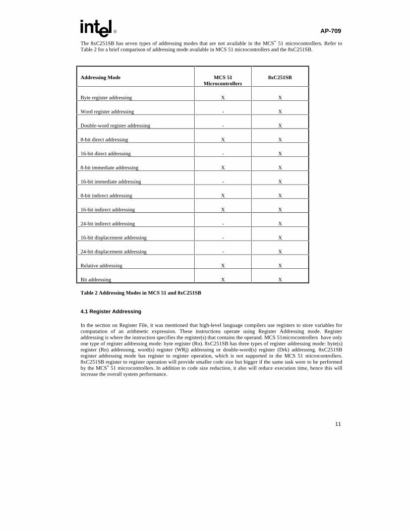
The 8xC251SB has seven types of addressing modes that are not available in the MCS® 51 microcontrollers. Refer toTable 2 for a brief comparison of addressing mode available in MCS 51 microcontrollers and the 8xC251SB.
Addressing Mode MCS 51Microcontrollers
8xC251SB
Byte register addressing X X
Word register addressing - X
Double-word register addressing - X
8-bit direct addressing X X
16-bit direct addressing - X
8-bit immediate addressing X X
16-bit immediate addressing - X
8-bit indirect addressing X X
16-bit indirect addressing X X
24-bit indirect addressing - X
16-bit displacement addressing - X
24-bit displacement addressing - X
Relative addressing X X
Bit addressing X X
Table 2 Addressing Modes in MCS 51 and 8xC251SB
4.1 Register Addressing
In the section on Register File, it was mentioned that high-level language compilers use registers to store variables forcomputation of an arithmetic expression. These instructions operate using Register Addressing mode. Registeraddressing is where the instruction specifies the register(s) that contains the operand. MCS 51microcontrollers have onlyone type of register addressing mode: byte register (Rn). 8xC251SB has three types of register addressing mode: byte(s)register (Rn) addressing, word(s) register (WRj) addressing or double-word(s) register (Drk) addressing. 8xC251SBregister addressing mode has register to register operation, which is not supported in the MCS 51 microcontrollers.8xC251SB register to register operation will provide smaller code size but bigger if the same task were to be performedby the MCS® 51 microcontrollers. In addition to code size reduction, it also will reduce execution time, hence this willincrease the overall system performance.
AP-709 E
12
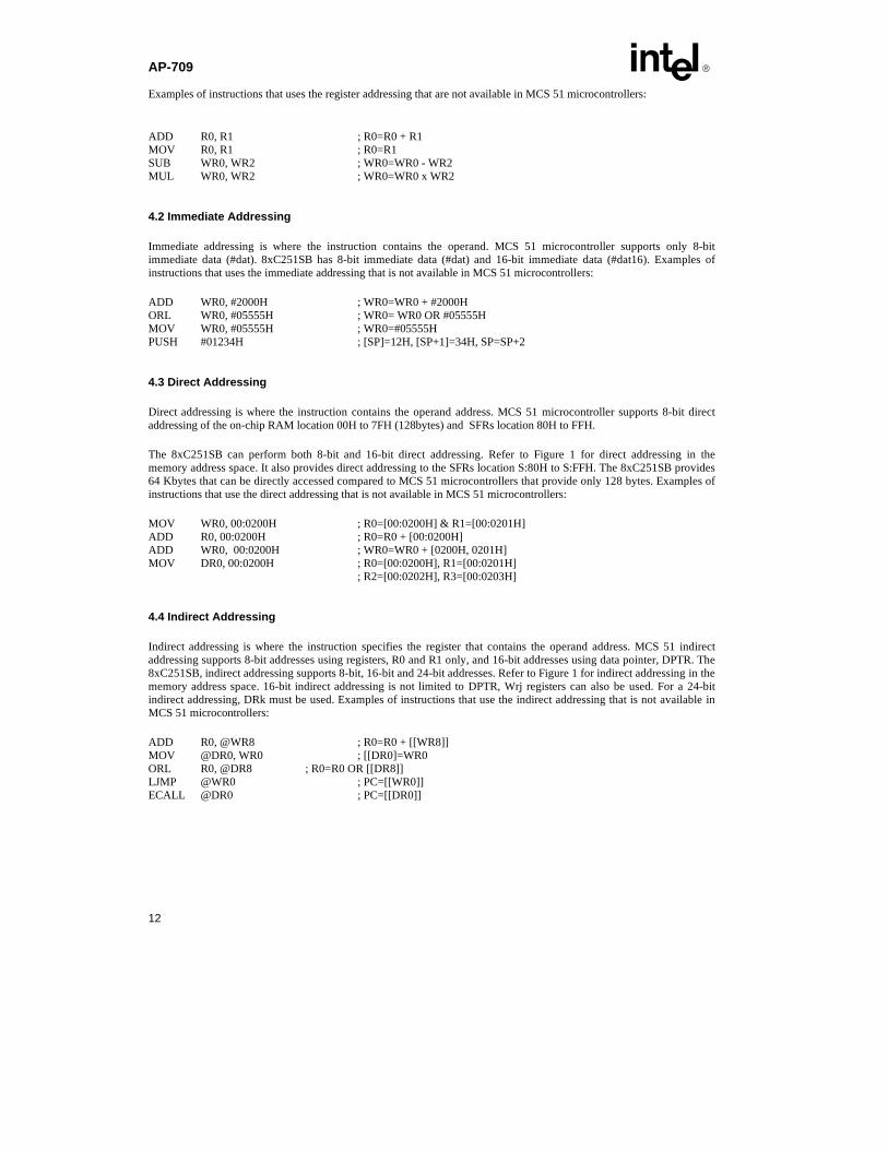
Examples of instructions that uses the register addressing that are not available in MCS 51 microcontrollers:
ADD R0, R1 ; R0=R0 + R1MOV R0, R1 ; R0=R1SUB WR0, WR2 ; WR0=WR0 - WR2MUL WR0, WR2 ; WR0=WR0 x WR2
4.2 Immediate Addressing
Immediate addressing is where the instruction contains the operand. MCS 51 microcontroller supports only 8-bitimmediate data (#dat). 8xC251SB has 8-bit immediate data (#dat) and 16-bit immediate data (#dat16). Examples ofinstructions that uses the immediate addressing that is not available in MCS 51 microcontrollers:
ADD WR0, #2000H ; WR0=WR0 + #2000HORL WR0, #05555H ; WR0= WR0 OR #05555HMOV WR0, #05555H ; WR0=#05555HPUSH #01234H ; [SP]=12H, [SP+1]=34H, SP=SP+2
4.3 Direct Addressing
Direct addressing is where the instruction contains the operand address. MCS 51 microcontroller supports 8-bit directaddressing of the on-chip RAM location 00H to 7FH (128bytes) and SFRs location 80H to FFH.
The 8xC251SB can perform both 8-bit and 16-bit direct addressing. Refer to Figure 1 for direct addressing in thememory address space. It also provides direct addressing to the SFRs location S:80H to S:FFH. The 8xC251SB provides64 Kbytes that can be directly accessed compared to MCS 51 microcontrollers that provide only 128 bytes. Examples ofinstructions that use the direct addressing that is not available in MCS 51 microcontrollers:
MOV WR0, 00:0200H ; R0=[00:0200H] & R1=[00:0201H]ADD R0, 00:0200H ; R0=R0 + [00:0200H]ADD WR0, 00:0200H ; WR0=WR0 + [0200H, 0201H]MOV DR0, 00:0200H ; R0=[00:0200H], R1=[00:0201H]
; R2=[00:0202H], R3=[00:0203H]
4.4 Indirect Addressing
Indirect addressing is where the instruction specifies the register that contains the operand address. MCS 51 indirectaddressing supports 8-bit addresses using registers, R0 and R1 only, and 16-bit addresses using data pointer, DPTR. The8xC251SB, indirect addressing supports 8-bit, 16-bit and 24-bit addresses. Refer to Figure 1 for indirect addressing in thememory address space. 16-bit indirect addressing is not limited to DPTR, Wrj registers can also be used. For a 24-bitindirect addressing, DRk must be used. Examples of instructions that use the indirect addressing that is not available inMCS 51 microcontrollers:
ADD R0, @WR8 ; R0=R0 + [[WR8]]MOV @DR0, WR0 ; [[DR0]=WR0ORL R0, @DR8 ; R0=R0 OR [[DR8]]LJMP @WR0 ; PC=[[WR0]]ECALL @DR0 ; PC=[[DR0]]

E AP-709
13
4.5 Displacement Addressing
Indirect displacement addressing is where the instruction specifies a register and an offset. This addressing scheme is notavailable in the MCS® 51 microcontroller but is available for MCS 251 data transfer instructions. These instructionstransfer bytes or words of data within the 16-Mbyte memory address space. Example of instructions that uses the indirectdisplacement addressing that is not available in MCS 51 microcontrollers:
MOV R0, @WR8 + 2000H ; R0=[[WR8]+#2000H]MOV WR0, @WR8 + 2000H ; R0=[[WR8] + #2000H], R1=[[WR8] + #2001H]MOV @WR4 + 2000H, WR0 ; [[WR4]+ #2000H]=WR0MOV @DR4 + 2000H, R0 ; [[DR4]+ #2000H]= R0
4.6 Relative Addressing
Relative addressing: The instruction contains an 8-bit signed offset from the next instruction to the target address.Relative addressing is also available for 8xC251SB. New instructions such as JE, JNE, JG, JLE, JSL, JSLE, JSG andJSGE use this relative addressing mode.
JG LABEL1 ; LABEL1 is a relative addressJSG LABEL2 ; LABEL2 is a relative address
4.7 Bit Addressing
Bit addressing is where the instructions contain the bit address. MCS 51 microcontrollers have only 16 bytes of on-chipRAM and 16 bytes of SFRs that are bit addressable, whereas the 8xC251SB has 96 bytes of on-chip RAM and all 128bytes of SFR locations that are bit addressable. Refer to Figure 1 for bit addressing in the memory address space.Examples of instructions that use the bit addressing that is not available in MCS 51 microcontrollers:
CLR S:7FH.0 ; Clear 7FH bit 0JNB S:099H.7, LABEL ; IF SBUF bit 7 not set THEN jump to LABEL
5.0 Instruction set
The instruction set of the MCS 51 microcontrollers is a subset of the instruction set found in the 8xC251SB. 8xC251SBsupports all the 255 instructions found in the MCS 51microcontrollers and many more new instructions. Instructionsfound in MCS 51 microcontroller will not be discussed here but they are available in the MCS 51 Microcontroller FamilyUser’s Manual and only new types of instructions will be discussed. These instructions can be grouped into the followinginstruction sets: arithmetic instructions, logical instructions, data transfer instructions, bit instructions and controlinstructions. In the next few sections, some of the new types of instructions will be discussed. A detailed description ofthese instructions is available in the 8xC251SB User’s Manual.
5.1 Arithmetic Instructions
In the MCS 51 microcontrollers, the arithmetic instructions operate only on byte data and must be done through theaccumulator. For applications that require intensive arithmetic operation, this becomes a bottle-neck. The 8xC251SBenhanced instruction set has register to register operations, this overcome the performance bottle-neck . The 8xC251SBprovides byte, word and double-word operations to further enhance computation of an arithmetic functions. Theseoperations are done through Rm and WRj registers. Refer to Appendix A for a list of arithmetic instructions thatcompares CPU cycle between MCS® 51 microcontrollers and 8xC251SB.

AP-709 E
14
Refer to Appendix B for examples of using new 8xC251SB arithmetic instructions.
5.2 Data Transfer Instructions
Most microcontroller-based systems spend a large amount of their CPU cycles (time) moving data from one location tothe other. If there was a way to decrease the CPU cycle (time) to transfer the data, then the overall performance of thesystem could be improved. 8xC251SB has a very rich set of MOV instructions that allow data to be moved either as byte,word or double-word.
Example 3a shows how MCS 51 microcontrollers move data from external data memory to register R0 using an indirectaddressing via the accumulator pointed by DPTR. The content in the accumulator is then moved to the register R0.
; Using MCS 51 microcontrollers to move data from external data memory to a registermov DPTR, #data_addr ; DPTR=data_addrclr A ; A=00Hmovx A, @A+DPTR ; A=[[A+DPTR]]mov R0, A ; R0=A
; Total number of MCS 51 microcontroller states= 30; Total number of MCS 51 microcontroller bytes= 7
Example 3a. Using MCS 51 microcontrollers for data move
Example 3b shows one of the many new MOV instructions provided by the 8xC251SB which bypasses the DPTR.Taking advantage of the register based architecture, the 8xC251SB is able to indirectly move the data to the register R0.
; Using 8xC251SB to move data from external data memory to a registermov WR2, #data_addr ; WR2=#data_addrmov R0, @WR2 ; R0=[[WR2]]
; Total number of 8xC251SB states= 4; Total number of 8xC251SB bytes= 7
Example 3b. Using the 8xC251SB for data move
Example 3a and 3b show that the 8xC251SB executes 7.5 times faster than the MCS 51 microcontrollers for the samecode size.
Example 4a illustrates how MCS 51 microcontrollers move 2 bytes of data stored sequentially in the on-chip data RAMto registers for an arithmetic operation or other user operation.
; MCS 51 microcontrollers to move 2 bytes of data stored sequentially in the on-chip; data RAM to registers
mov R0, addr_data_1 ; R0=addr_data_1mov R1, addr_data_2 ; R1=addr_data_2{Arithmetic operation or other user o peration}
; Total number of MCS 51 microcontroller states= 24; Total number of MCS 51 microcontroller bytes= 4

E AP-709
15
Example 4a. Another example of the using MCS 51 microcontrollers for data move
Example 4b shows how the 8xC251SB moves data stored in the on-chip general purpose RAM for arithmetic operationor other user operation. The 8xC251SB has reduced the execution time from 24 states to only 3 states.
; 8xC251SB to move 2 bytes of data stored sequentially in the on-chip data RAM to registersmov WR0, addr_data_1 ; R0=[addr_data_1] & R1=[addr_data_2]{Arithmetic operation or other user operation}
; Total number of 8xC251SB states= 3; Total number of 8xC251SB bytes= 3
Example 4b. Another example of using 8xC251SB for data move
Example 4a and 4b show that the 8xC251SB executes 8 times faster than the MCS® 51 microcontrollers. Also there is a13% code size reduction using the 8xC251SB.
Refer to Appendix A for a list of data transfer instructions that compares CPU cycle between MCS 51 microcontrollersand the 8xC251SB.
Refer to Appendix C for more examples that use the 8xC251SB data transfer instructions.
5.3 Logical Instructions
MCS 51 microcontrollers logical instructions can only operate on 8-bit data. 8xC251SB logical instruction supports 8-bitand 16-bit data operation. Register to register operation can be performed on the 8xC251SB but not on the MCS 51microcontrollers. By using the Rm and WRj registers to resolve the accumulator based bottle-neck of the MCS 51microcontrollers, overall system performance is enhanced.
Example 5a. illustrate how MCS 51 microcontrollers logically rotate the content of R0 register. Firstly, the content of R0is moved to the accumulator. Accumulator is then rotated. Finally, the result is moved back to R0 register.
; MCS 51 microcontrollers to logically rotate the content of R0 register.mov A, R0 ; A=[R0]rl A ; Rotate accumulator to the leftmov R0, A ; R0=A
; Total number of MCS 51 microcontroller states= 18; Total number of MCS 51 microcontroller bytes= 3
Example 5a. MCS 51 microcontrollers logically rotate the content of R0 register
Example 5b. illustrates how the 8xC251SB can directly rotate the content of R0 register without using the accumulator.
; 8xC251SB directly rotate R0sll R0 ; Rotate R0 to the left
; Total number of 8xC251SB states= 1; Total number of 8xC251SB bytes= 2

AP-709 E
16
Example 5b. 8xC251SB logically rotate the content of R0 register
Example 5a and 5b show that the 8xC251SB executes 18 times faster than the MCS® 51 microcontrollers. Also there is a15% code size reduction using the 8xC251SB.
Refer to Appendix A for a list of logical instructions that compares the CPU cycle between MCS 51 microcontrollers and8xC251SB.
Refer to Appendix D for more examples that use the 8xC251SB logical instructions.
5.4 Bit Instructions
MCS 51 microcontrollers bit instructions operate on 16 bytes of the internal data memory address space and 16 bytes ofthe SFR space. In comparison, the 8xC251SB bit instructions operate on a larger memory region, that is, 96 bytes of thememory address space and 128 bytes of the SFR space. With the increase in the bit addressable space, this allows moreBoolean variables and SFRs registers to be controlled directly.
Refer to Appendix A for a list of bit instructions that compares CPU cycle between MCS 51 microcontrollers and8xC251SB.
5.5 Control Instructions
8xC251SB offers 15 new control instructions. Some of these new instructions, for example ECALL, ERET and EJMP,allow the user to take advantage of the entire 8xC251SB memory space. High level languages such as C can takeadvantage of these new control instructions, JE, JNE, JG, JLE, JSL, JSLE, JSG and JSGE together with arithmeticinstructions such as SUB, ADD, CMP and etc.
Refer to Appendix A for a list of control instructions that compares CPU cycle between MCS 51 microcontrollers and8xC251SB.
Refer to Appendix E for examples that use the 8xC251SB logical instructions.
6.0 CONCLUSION
This application note coveres the programming aspects of 8xC251SB and some software performance comparisonbetween the MCS 51 microcontrollers and 8xC251SB. It shows how the 8xC251SB executes much faster than the MCS51 microcontrollers. It also illustrates how the 8xC251SB requires smaller code space versus MCS 51 microcontrollers.This application note also shows that the 8xC251SB have higher performance, an increased memory mix and addressing,efficient high-level language support, enhanced instructions set to the 8-bit embedded microcontroller market availabletoday.

E AP-709
17
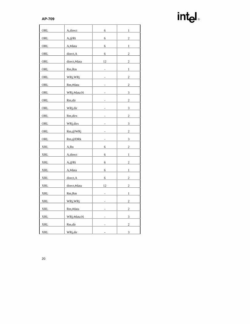
APPENDIX A: Instruction Cycle Improvement
INSTRUCTION SET SUMMARY
ARITHMETIC OPERATIONS
Mnemonic Note MCS® 51Controller
States
8xC251SB
States *1
ADD A,Rn 6 2
ADD A,direct 6 1
ADD A,@Ri 6 2
ADD A,#data 6 1
ADD Rm,Rm - 1
ADD WRj,WRj - 2
ADD Rm,#data - 2
ADD WRj,#data16 - 3
ADD Rm,dir - 2
ADD WRj,dir - 3
ADD Rm,dirx - 2
ADD WRj,dirx - 3
ADD Rm,@WRj - 2
ADD Rm,@DRk - 3
ADDC A,Rn 6 2
ADDC A,direct 6 1
ADDC A,@Ri 6 2
ADDC A,#data 6 1
SUB Rm,Rm - 1
SUB WRj,WRj - 2
SUB Rm,#data - 2

AP-709 E
18
SUB WRj,#data16 - 3
SUB Rm,dir - 2
SUB WRj,dir - 3
SUB Rm,dirx - 2
SUB WRj,dirx - 3
SUB Rm,@WRj - 2
SUB Rm,@DRk - 3
SUBB A,Rn 6 2
SUBB A,direct 6 1
SUBB A,@Ri 6 2
SUBB A,#data 6 1
INC A 6 1
INC Rn 6 2
INC direct 6 2
INC @Ri 6 3
INC Rm, #short - 1
INC WRj, #short - 1
DEC A 6 1
DEC Rn 6 2
DEC direct 6 2
DEC @Ri 6 3
DEC Rm, #short - 1
DEC WRj, #short - 1
INC DPTR 12 1
MUL AB 24 5
MUL Rm,Rm - 5
MUL WRj,WRj - 11
E AP-709
19
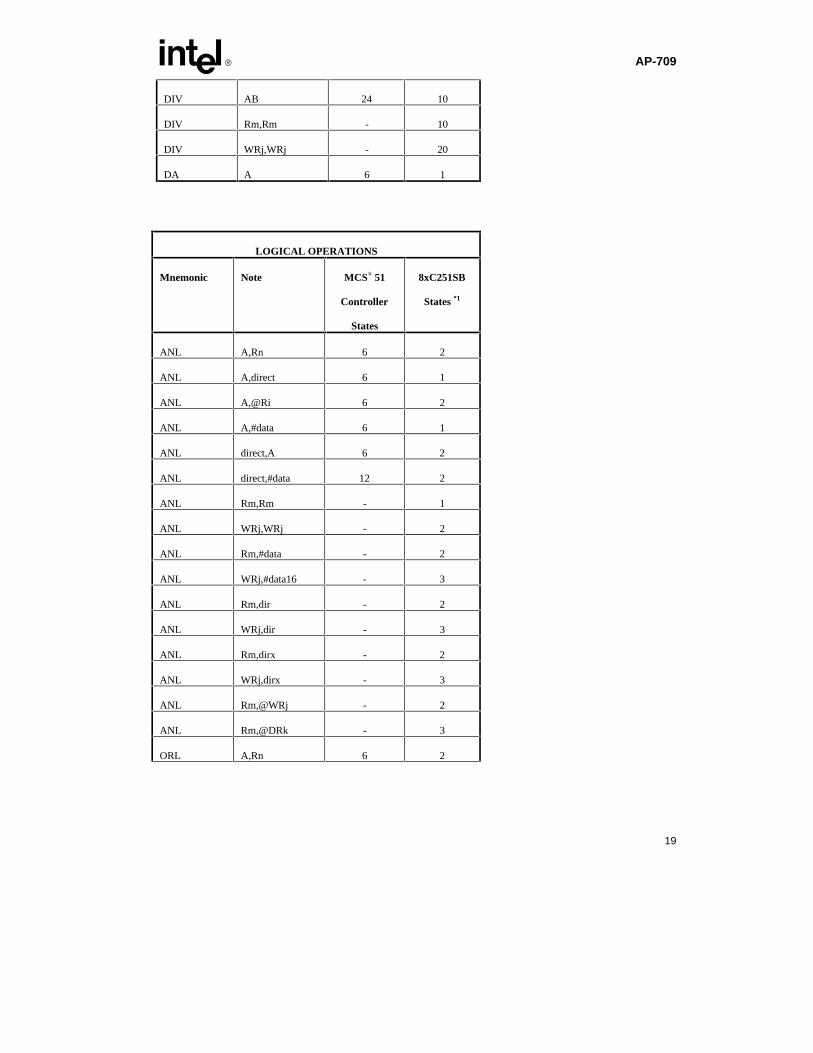
DIV AB 24 10
DIV Rm,Rm - 10
DIV WRj,WRj - 20
DA A 6 1
LOGICAL OPERATIONS
Mnemonic Note MCS® 51
Controller
States
8xC251SB
States *1
ANL A,Rn 6 2
ANL A,direct 6 1
ANL A,@Ri 6 2
ANL A,#data 6 1
ANL direct,A 6 2
ANL direct,#data 12 2
ANL Rm,Rm - 1
ANL WRj,WRj - 2
ANL Rm,#data - 2
ANL WRj,#data16 - 3
ANL Rm,dir - 2
ANL WRj,dir - 3
ANL Rm,dirx - 2
ANL WRj,dirx - 3
ANL Rm,@WRj - 2
ANL Rm,@DRk - 3
ORL A,Rn 6 2
AP-709 E
20
ORL A,direct 6 1
ORL A,@Ri 6 2
ORL A,#data 6 1
ORL direct,A 6 2
ORL direct,#data 12 2
ORL Rm,Rm - 1
ORL WRj,WRj - 2
ORL Rm,#data - 2
ORL WRj,#data16 - 3
ORL Rm,dir - 2
ORL WRj,dir - 3
ORL Rm,dirx - 2
ORL WRj,dirx - 3
ORL Rm,@WRj - 2
ORL Rm,@DRk - 3
XRL A,Rn 6 2
XRL A,direct 6 1
XRL A,@Ri 6 2
XRL A,#data 6 1
XRL direct,A 6 2
XRL direct,#data 12 2
XRL Rm,Rm - 1
XRL WRj,WRj - 2
XRL Rm,#data - 2
XRL WRj,#data16 - 3
XRL Rm,dir - 2
XRL WRj,dir - 3

E AP-709
21
XRL Rm,dirx - 2
XRL WRj,dirx - 3
XRL Rm,@WRj - 2
XRL Rm,@DRk - 3
CLR A 6 1
CPL A 6 1
RL A 6 1
RL Rm - 1
RL WRj - 1
RLC A 6 1
RLC Rm - 1
RLC WRj - 1
RR A 6 1
RR Rm - 1
RR WRj - 1
RRC A 6 1
RRC Rm - 1
RRC WRj - 1
SLL Rm - 1
SLL WRj - 1
SRA Rm - 1
SRA WRj - 1
SRL Rm - 1
SRL WRj - 1
SWAP A 6 2
AP-709 E
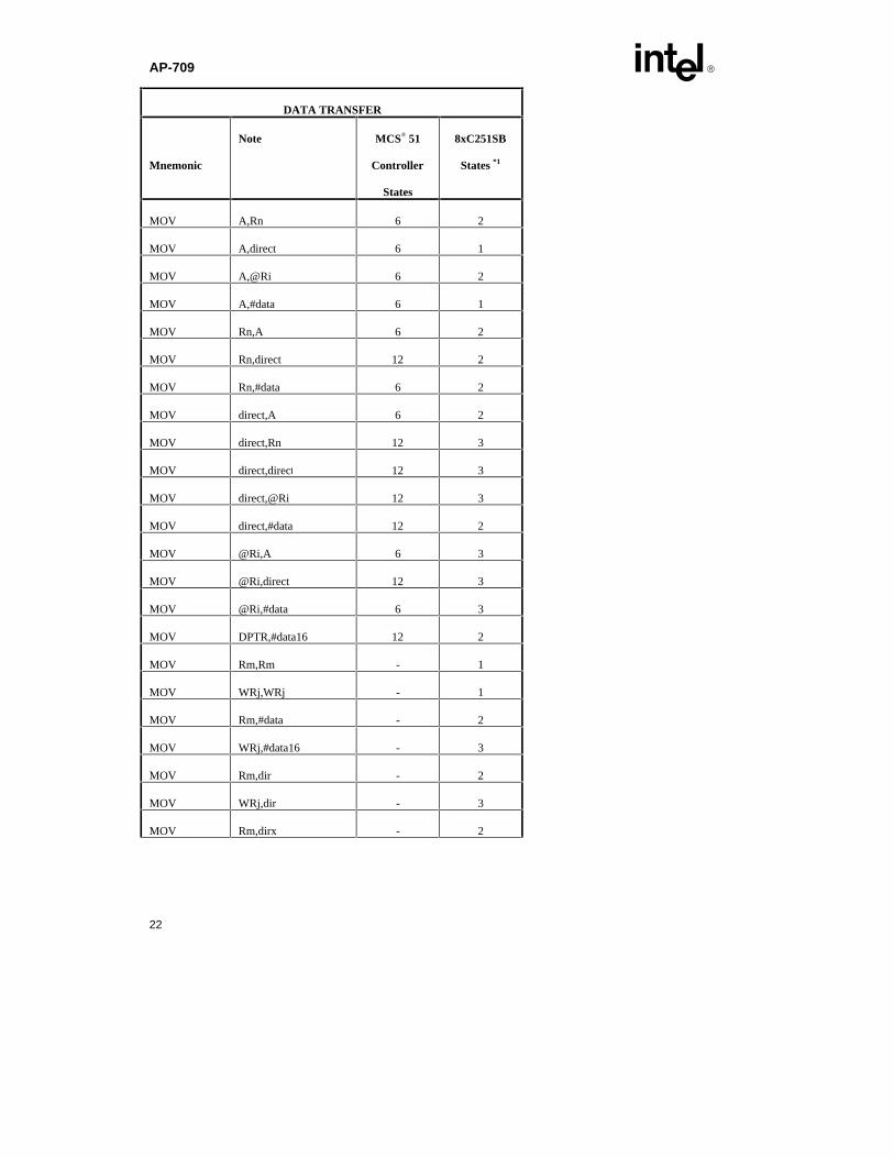
22
DATA TRANSFER
Mnemonic
Note MCS® 51
Controller
States
8xC251SB
States *1
MOV A,Rn 6 2
MOV A,direct 6 1
MOV A,@Ri 6 2
MOV A,#data 6 1
MOV Rn,A 6 2
MOV Rn,direct 12 2
MOV Rn,#data 6 2
MOV direct,A 6 2
MOV direct,Rn 12 3
MOV direct,direct 12 3
MOV direct,@Ri 12 3
MOV direct,#data 12 2
MOV @Ri,A 6 3
MOV @Ri,direct 12 3
MOV @Ri,#data 6 3
MOV DPTR,#data16 12 2
MOV Rm,Rm - 1
MOV WRj,WRj - 1
MOV Rm,#data - 2
MOV WRj,#data16 - 3
MOV Rm,dir - 2
MOV WRj,dir - 3
MOV Rm,dirx - 2

E AP-709
23
MOV WRj,dirx - 3
MOV Rm,@WRj - 2
MOV Rm,@DRk - 3
MOV dir, Rm - 2
MOV dir, WRj - 3
MOV dirx, Rm - 2
MOV dirx, WRj - 3
MOV @WRj, Rm - 3
MOV @DRk, Rm - 4
MOV Rm,@WRj+dis - 5
MOV WRj,@WRj+dis - 6
MOV Rm,@DRk+dis - 6
MOV WRj,@DRk+dis - 7
MOV @WRj+dis, Rm - 6
MOV @WRj+dis, WRj - 8
MOV @DRk+dis, Rm - 7
MOV @DRk+dis, WRj - 9
MOVC A,@A+DPTR 12 5
MOVC A,@A+PC 12 6
MOVX A,@Ri 12 4
MOVX A,@DPTR 12 4
MOVX @Ri,A 12 5
MOVX @DPTR,A 12 5
PUSH direct B/W 12 3
PUSH #data - 3
PUSH #data16 - 5
PUSH dirx B/W - 3
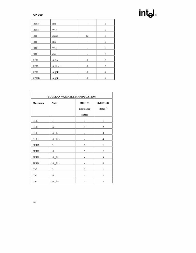
AP-709 E
24
PUSH Rm - 3
PUSH WRj - 5
POP direct 12 3
POP Rm - 2
POP WRj - 5
POP dirx - 3
XCH A,Rn 6 3
XCH A,direct 6 3
XCH A,@Ri 6 4
XCHD A,@Ri 6 4
BOOLEAN VARIABLE MANIPULATION
Mnemonic Note MCS® 51
Controller
States
8xC251SB
States *1
CLR C 6 1
CLR bit 6 2
CLR bit_dir - 3
CLR bit_dirx - 4
SETB C 6 1
SETB bit 6 2
SETB bit_dir - 3
SETB bit_dirx - 4
CPL C 6 1
CPL bit - 2
CPL bit_dir - 3

E AP-709
25
CPL bit_dirx - 4
ANL C,bit 12 1
ANL C, bit_dir - 2
ANL C, bit_dirx - 3
ANL/ C,/bit 12 1
ANL/ C, /bit_dir - 2
ANL/ C, /bit_dirx - 3
ORL C,bit 12 1
ORL C, bit_dir - 2
ORL C, bit_dirx - 3
ORL/ C,/bit 12 1
ORL/ C, /bit_dir - 2
ORL/ C, /bit_dirx - 3
MOV C,bit 6 1
MOV C, bit_dir - 2
MOV C, bit_dirx - 3
MOV bit,C 12 2
MOV bit_dir, C - 3
MOV bit_dirx, C - 4
JC rel 12 1
JNC rel 12 1
JB bit,rel 12 2
JB bit,relx - 3
JNB bit,rel 12 2
JNB bit,relx - 3
JBC bit,rel 12 2
JBC bit,relx - 3

AP-709 E
26
PROGRAM BRANCHING
Mnemonic
Note MCS® 51
Controller
States
8xC251SB
States *1
ACALL addr11 12 6
ECALL addr24 - 12
ECALL @DRk - 12
LCALL addr16 12 6
ERET - 8
RET 12 6
RETI 12 8
AJMP addr11 12 3
EJMP addr24 - 4
EJMP @DRk - 5
LJMP addr16 12 4
SJMP rel 12 3
JMP @A+DPTR 12 4
JZ rel 12 2
JNZ rel 12 2
CJNE A,direct,rel 12 3
CJNE A,#data,rel 12 2
CJNE Rn,#data,rel 12 3
CJNE @Ri,#data,rel 12 3
DJNZ Rn,rel 12 3
DJNZ direct,rel 12 3

E AP-709
27
NOP 6 1
NOTE:
*1 : The 8xC251SB execute from internal code memory and the pipeline is full.

AP-709 E
28
APPENDIX B: Examples of new 8xC251SB Arithmetic Instruction
; Example 1:; Description: Perform 8 bit data addition using registers.; R0=R0+R1.;****************************************************************************; ***MCS® 51 Microcontroller***
mov A, R0add A, R1 ; A=R0+R1mov R0, A ; R0=A
; Total number of MCS 51 microcontroller states=18; Total number of MCS 51 microcontroller bytes= 3
; ***8xC251SB microcontroller***add R0, R1 ; R0=R0+R1
; Total number of 8xC251SB microcontroller states= 1; Total number of 8xC251SB microcontroller bytes= 2
; Example 2:; Description: Perform 16 bit data addition using registers.; [R0,R1]=#1234H+#5678H.;****************************************************************************; ***MCS 51 microcontroller***
mov R1, #78H ; R1=#78Hmov R0, #56H ; R0=#56Hmov A, #34H ; A=#34Hadd A, R1 ; A=#34H+78Hmov R1, A ; R1=Amov A, #12H ; A=#12Haddc A, R0 ; A=#12H+#56Hmov R0, A ; R0=A
; Total number of MCS 51 microcontroller states= 54; Total number of MCS 51 microcontroller bytes= 12
; ***8xC251SB microcontroller***; Using ADD WRj, WRj
mov WR0, #1234H ; Operand 1mov WR2, #5678H ; Operand 2add WR0, WR2 ; WR0=#1234H + #5678H
; Total number of 8xC251SB microcontroller states= 6; Total number of 8xC251SB microcontroller bytes= 10
; Example 3:; Description: Double-word addition.; Double-word reguster= #12345678H + #87654321H;****************************************************************************; *** MCS 51 Microcontroller ***
mov A, #78H ; A=#78Hmov R3, #21H ; R3=#21Hadd A, R3 ; A=A+R0mov R3, A ; R3=Amov A, #56H ; A=#56Hmov R2, #43H ; R2=#43Haddc A, R0 ; A=A+R2mov R2, A ; R2=A

E AP-709
29
mov A, #34H ; A=#34Hmov R1, #65H ‘ ; R1=56Haddc A, R1 ; A=A+R1mov R1, A; ; R1=Amov A, #12H ; A=#12Hmov R0, #87H ; R0=#87addc A, R0 ; A=A+R0mov R0, A ; R0=A
; Total number of MCS® 51 Microcontroller states= 102; Total number of MCS 51 Microcontroller bytes = 24
; *** 8xC251SB ***; Using ADD DRj, DRj instructions to perform 4 bytes of addition operation.
mov WR0, #1234H ; WR0=#1234Hmov WR2, #1234H ; WR2=#5678Hmov WR4, #4321H ; WR4=#8765Hmov WR6, #4321H ; WR6=#4321Hadd DR0, DR4 ; WR0=WR0+WR2
; Total number of 8xC251SB states= 12; Total number of 8xC251SB bytes= 18
; Example 4:; Description: Perform 8 bit data multiplication; R0=R0 x R1;****************************************************************************; ***MCS 51 microcontroller***
mov A, #12H ; A=#12Hmov B, #34H ; B=#34Hmul AB ; A x Bmov R1, A ; R1=Low byte resultmov R0, B ; R0=High byte result
; Total number of MCS 51 microcontroller states= 60; Total number of MCS 51 microcontroller bytes= 9
; ***8xC251SB microcontroller***mov WR0, #1234H ; WR0=#1234Hmul R0, R1 ; WR0= R0 x R1
; Total number of 8xC251SB microcontroller states= 7; Total number of 8xC251SB microcontroller bytes= 6
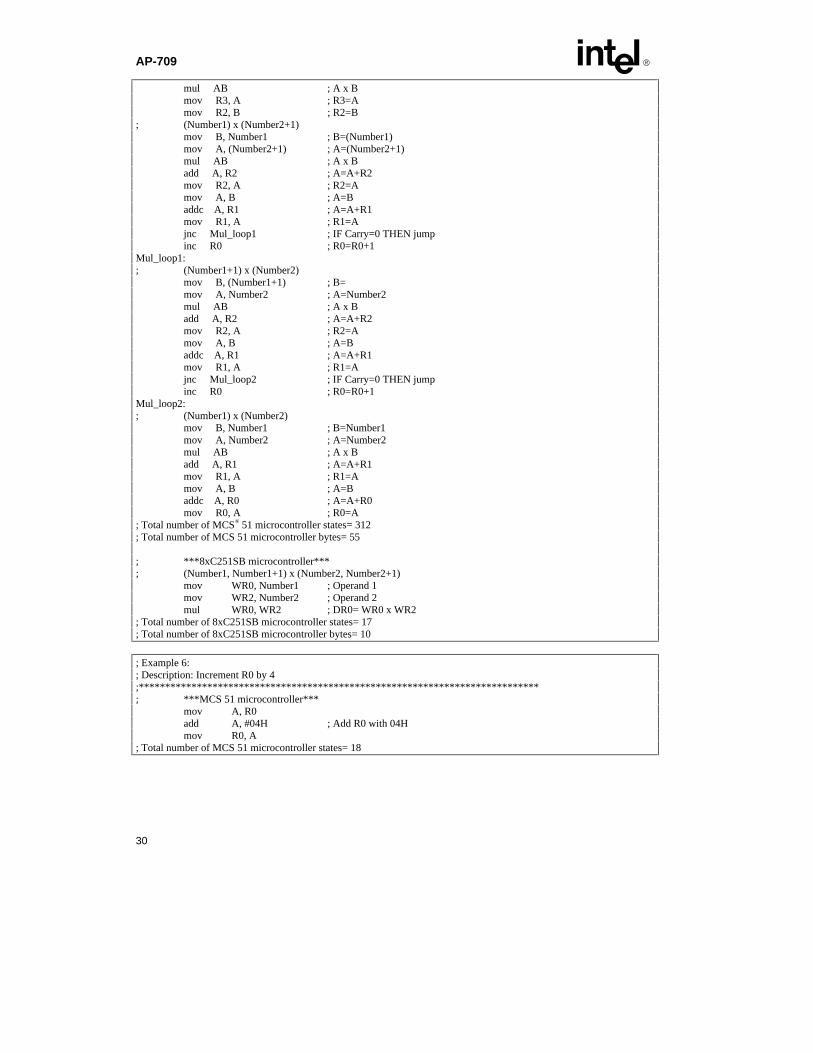
; Example 5:; Description: Multiply 2 16-bit numbers and store in registers.;****************************************************************************; Number1 (Number1+1); X Number2 (Number2+1); -----------------------------------------; R0 R1 R2 R3; R0=Most significant byte of double-word result; R3=Least significant byte of double-word result; ***MCS 51 Microcontroller***; (Number1+1) x (Number2+1)
mov R0, #00H ; R0=#00H mov R1, #00H ; R1=#00H mov B, (Number1+1) ; B=(Number1+1) mov A, (Number2+1) ; A=(Number2+1)
AP-709 E
30
mul AB ; A x B mov R3, A ; R3=A mov R2, B ; R2=B; (Number1) x (Number2+1) mov B, Number1 ; B=(Number1) mov A, (Number2+1) ; A=(Number2+1) mul AB ; A x B add A, R2 ; A=A+R2 mov R2, A ; R2=A mov A, B ; A=B addc A, R1 ; A=A+R1 mov R1, A ; R1=A jnc Mul_loop1 ; IF Carry=0 THEN jump inc R0 ; R0=R0+1Mul_loop1:; (Number1+1) x (Number2) mov B, (Number1+1) ; B= mov A, Number2 ; A=Number2 mul AB ; A x B add A, R2 ; A=A+R2 mov R2, A ; R2=A mov A, B ; A=B addc A, R1 ; A=A+R1 mov R1, A ; R1=A jnc Mul_loop2 ; IF Carry=0 THEN jump inc R0 ; R0=R0+1Mul_loop2:; (Number1) x (Number2) mov B, Number1 ; B=Number1 mov A, Number2 ; A=Number2 mul AB ; A x B add A, R1 ; A=A+R1 mov R1, A ; R1=A mov A, B ; A=B addc A, R0 ; A=A+R0 mov R0, A ; R0=A; Total number of MCS® 51 microcontroller states= 312; Total number of MCS 51 microcontroller bytes= 55
; ***8xC251SB microcontroller***; (Number1, Number1+1) x (Number2, Number2+1)
mov WR0, Number1 ; Operand 1mov WR2, Number2 ; Operand 2mul WR0, WR2 ; DR0= WR0 x WR2
; Total number of 8xC251SB microcontroller states= 17; Total number of 8xC251SB microcontroller bytes= 10
; Example 6:; Description: Increment R0 by 4;****************************************************************************; ***MCS 51 microcontroller***
mov A, R0add A, #04H ; Add R0 with 04Hmov R0, A
; Total number of MCS 51 microcontroller states= 18

E AP-709
31
; Total number of MCS® 51 microcontroller bytes= 4
; ***8xC251SB microcontroller***inc R0, #04H ; Increment R0 by 4 times
; Total number of 8xC251SB microcontroller states= 1; Total number of 8xC251SB microcontroller bytes= 2
; Example 7:; Description: Decrement R0 by 4;****************************************************************************; ***MCS 51 microcontroller***
mov A, R0 ; A=R0subb A, #04H ; A=A-04Hmov R0, A ; R0=A
; Total number of MCS 51 microcontroller states= 18; Total number of MCS 51 microcontroller bytes = 4
; ***8xC251SB microcontroller***dec R0, #04H ; R0=R0-04H
; Total number of 8xC251SB microcontroller states= 1; Total number of 8xC251SB microcontroller bytes= 2
; Example 8:; Description: Compare data in R0 and R1 and jump accordingly.;****************************************************************************; *** MCS 51 Microcontroller ***
mov A, R0 ; A=R0cjne A, 01H, NOT_EQUAL ; If R0 <> R1 Then
EQUAL:; Total number of MCS 51 Microcontroller states= 18; Total number of MCS 51 Microcontroller bytes= 4
; *** 8xC251SB ***; Using JNE and CMP instructions.
cmp R0, R1 ; If R0 ? R1jne NOT_EQUAL ; If R0<>R1 Then Jump
EQUAL:; Total number of 8xC251SB states= 2; Total number of 8xC251SB bytes= 4

AP-709 E
32
APPENDIX C: Examples of new 8xC251SB Data Transfer Instruction
; Example 1:; Description: Copy bytes from register to register.; Data word store in R0 (High-byte) and R1 (Low-byte) move to R4 and R5.;****************************************************************************; *** MCS® 51 Microcontroller ***; There is no instruction for register to register operation, hence use direct a ddressing.
mov 04H, 00H ; R4=R0mov 05H, 01H ; R5=R1
; Total number of MCS 51 Microcontroller states= 24; Total number of MCS 51 Microcontroller bytes=6
; *** 8xC251SB ***mov WR4, WR0 ; R4=R0 & R5=R1
; Total number of 8xC251SB cycles= 1; Total number of 8xC251SB bytes = 2
; Example 2:; Description: Move a word data from external memory to internal data memory.;****************************************************************************; *** MCS 51 Microcontroller ***
; Setup pointermov DPL, (SRC+1) ; DPL=(SRC+1)mov DPH, SRC ; DPL=SRC; Get data & Store datamovx A, @DPTR ; A=[[DPTR]]mov DST, A ; DST=Ainc DPTR ; DPTR=DPTR+1movx A, @DPTR ; A=[[DPTR]]mov DST+1, A ; (DST+1)=A
; Total number of MCS 51 Microcontroller states= 72; Total number of MCS 51 Microcontroller bytes= 24
; *** 8xC251SB ***mov WR0, #SRC ; WR0=SRCmov WR2, @WR0 ; WR2=[[WR0]]mov DST, WR2; DST=WR2
; Total number of 8xC251SB states= 10; Total number of 8xC251SB bytes= 9
; Example 3:; Description: Move one byte of data from code memory to register.;****************************************************************************; *** MCS® 51 Microcontroller ***
; Setup pointermov DPL, (SRC+1) ; DPL=(SRC+1)mov DPH, SRC ; DPH=SRC; Get and store data byteclr A ; A=00Hmovc A, @A+DPTR ; A=[[A+DPTR]]mov R0, A ; R0=A
; Total number of MCS 51 Microcontroller states= 48; Total number of MCS 51 Microcontroller bytes= 9
E AP-709
33
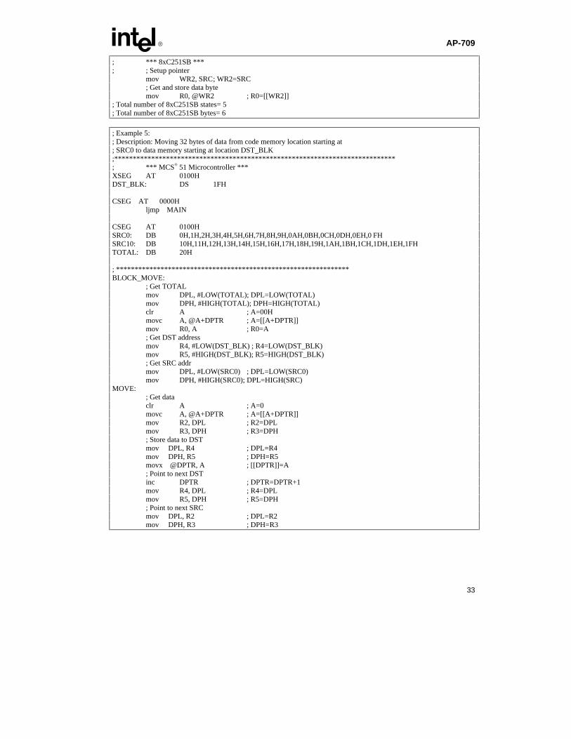
; *** 8xC251SB ***; ; Setup pointer
mov WR2, SRC; WR2=SRC; Get and store data bytemov R0, @WR2 ; R0=[[WR2]]
; Total number of 8xC251SB states= 5; Total number of 8xC251SB bytes= 6
; Example 5:; Description: Moving 32 bytes of data from code memory location starting at; SRC0 to data memory starting at location DST_BLK;****************************************************************************; *** MCS® 51 Microcontroller ***XSEG AT 0100HDST_BLK: DS 1FH
CSEG AT 0000Hljmp MAIN
CSEG AT 0100HSRC0: DB 0H,1H,2H,3H,4H,5H,6H,7H,8H,9H,0AH,0BH,0CH,0DH,0EH,0 FHSRC10: DB 10H,11H,12H,13H,14H,15H,16H,17H,18H,19H,1AH,1BH,1CH,1DH,1EH,1FHTOTAL: DB 20H
; ***************************************************************BLOCK_MOVE:
; Get TOTALmov DPL, #LOW(TOTAL); DPL=LOW(TOTAL)mov DPH, #HIGH(TOTAL); DPH=HIGH(TOTAL)clr A ; A=00Hmovc A, @A+DPTR ; A=[[A+DPTR]]mov R0, A ; R0=A; Get DST addressmov R4, #LOW(DST_BLK) ; R4=LOW(DST_BLK)mov R5, #HIGH(DST_BLK); R5=HIGH(DST_BLK); Get SRC addrmov DPL, #LOW(SRC0) ; DPL=LOW(SRC0)mov DPH, #HIGH(SRC0); DPL=HIGH(SRC)
MOVE:; Get dataclr A ; A=0movc A, @A+DPTR ; A=[[A+DPTR]]mov R2, DPL ; R2=DPLmov R3, DPH ; R3=DPH; Store data to DSTmov DPL, R4 ; DPL=R4mov DPH, R5 ; DPH=R5movx @DPTR, A ; [[DPTR]]=A; Point to next DSTinc DPTR ; DPTR=DPTR+1mov R4, DPL ; R4=DPLmov R5, DPH ; R5=DPH; Point to next SRCmov DPL, R2 ; DPL=R2mov DPH, R3 ; DPH=R3

AP-709 E
34
inc DPTR ; DPTR=DPTR+1djnz R0, MOVE ; IF R0<>0 THEN jmp to MOVE
; ***************************************************************; Total number of MCS 51 Microcontroller states= 5262; Total number of MCS 51 Microcontroller bytes= 42
retMAIN:
acall BLOCK_MOVEEND
; ***************************************************************; *** 8xC251SB ***DSEG AT 00:0100HDST_BLK: DS 1FH
CSEG AT FF:0000Hljmp MAIN
CSEG AT FF:0100HSRC0: DB 0H,1H,2H,3H,4H,5H,6H,7H,8H,9H,0AH,0BH,0CH,0DH,0EH,0FHSRC10: DB 10H,11H,12H,13H,14H,15H,16H,17H,18H,19H,1AH,1BH,1CH,1DH,1EH,1FHTOTAL: DB 10H
; ***************************************************************BLOCK_MOVE:
; Get TOTALmov WR24, #00FFH ; WR24=#00FFHmov WR26, #LOW16(TOTAL) ; DPTR=#TOTALmov R0, @DR24 ; R0=[[DR24]]; Get DST addressmov WR4, #DST_BLK ; WR4=#DST_BLK; Get SRC addrmov WR26, #LOW16(SRC0); WR26=#LOW(SRC0)
MOVE:; Get datamov WR2, @DR24 ; WR2=[[DR24]]; Store to DSTmov @WR4, WR2 ; [[WR4]]=WR2; Point to next SRC & DSTinc WR26, #2 ; WR26=WR26+2inc WR4, #2 ; WR4=WR4+2djnz R0, MOVE ; IF R0<>0 THEN jump to MOVE
; ***************************************************************; Total number of 8xC251SB states= 263; Total number of 8xC251SB bytes= 33
retMAIN:
acall MOVEEND
E AP-709
35
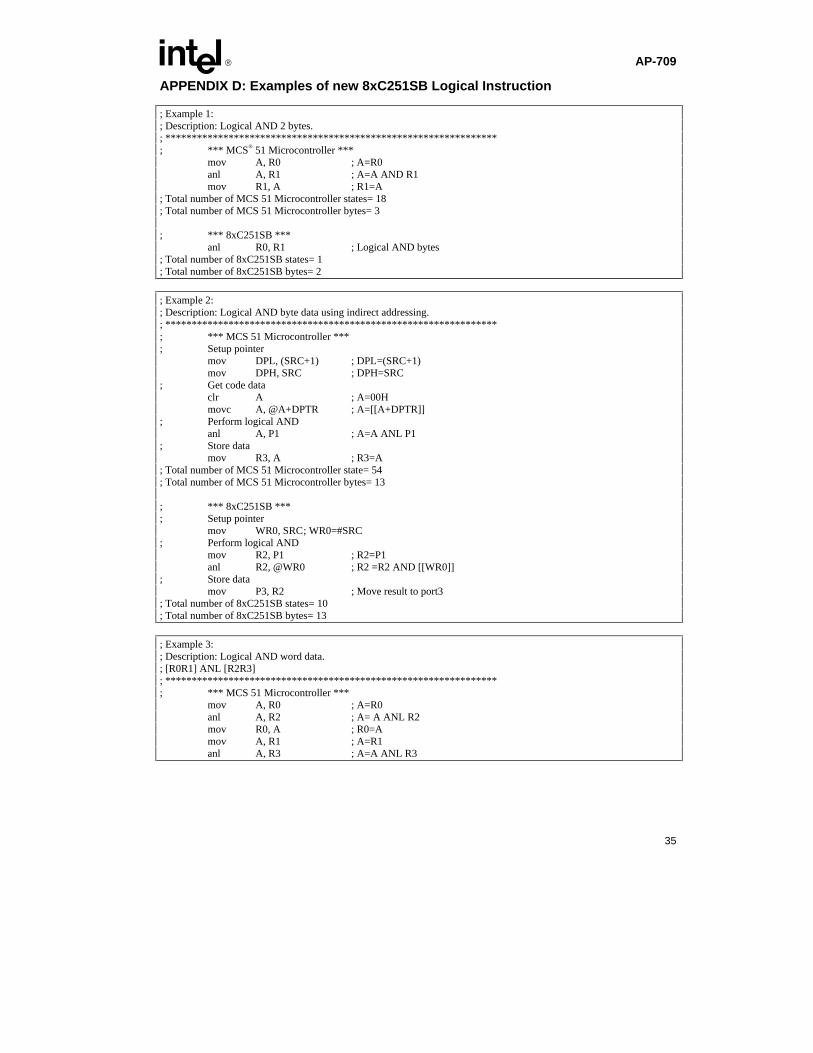
APPENDIX D: Examples of new 8xC251SB Logical Instruction
; Example 1:; Description: Logical AND 2 bytes.; ***************************************************************; *** MCS® 51 Microcontroller ***
mov A, R0 ; A=R0anl A, R1 ; A=A AND R1mov R1, A ; R1=A
; Total number of MCS 51 Microcontroller states= 18; Total number of MCS 51 Microcontroller bytes= 3
; *** 8xC251SB ***anl R0, R1 ; Logical AND bytes
; Total number of 8xC251SB states= 1; Total number of 8xC251SB bytes= 2
; Example 2:; Description: Logical AND byte data using indirect addressing.; ***************************************************************; *** MCS 51 Microcontroller ***; Setup pointer
mov DPL, (SRC+1) ; DPL=(SRC+1)mov DPH, SRC ; DPH=SRC
; Get code dataclr A ; A=00Hmovc A, @A+DPTR ; A=[[A+DPTR]]
; Perform logical ANDanl A, P1 ; A=A ANL P1
; Store datamov R3, A ; R3=A
; Total number of MCS 51 Microcontroller state= 54; Total number of MCS 51 Microcontroller bytes= 13
; *** 8xC251SB ***; Setup pointer
mov WR0, SRC; WR0=#SRC; Perform logical AND
mov R2, P1 ; R2=P1anl R2, @WR0 ; R2 =R2 AND [[WR0]]
; Store datamov P3, R2 ; Move result to port3
; Total number of 8xC251SB states= 10; Total number of 8xC251SB bytes= 13
; Example 3:; Description: Logical AND word data.; [R0R1] ANL [R2R3]; ***************************************************************; *** MCS 51 Microcontroller ***
mov A, R0 ; A=R0anl A, R2 ; A= A ANL R2mov R0, A ; R0=Amov A, R1 ; A=R1anl A, R3 ; A=A ANL R3
AP-709 E
36
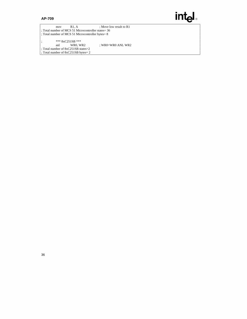
mov R1, A ; Move low result to R1; Total number of MCS 51 Microcontroller states= 36; Total number of MCS 51 Microcontroller bytes= 8
; *** 8xC251SB ***anl WR0, WR2 ; WR0=WR0 ANL WR2
; Total number of 8xC251SB states=2; Total number of 8xC251SB bytes= 2
E AP-709
37
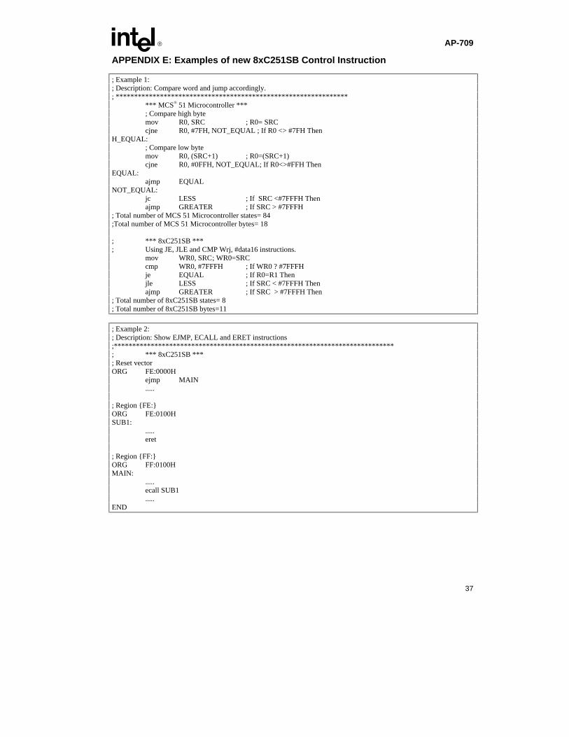
APPENDIX E: Examples of new 8xC251SB Control Instruction
; Example 1:; Description: Compare word and jump accordingly.; ***************************************************************
*** MCS® 51 Microcontroller ***; Compare high bytemov R0, SRC ; R0= SRCcjne R0, #7FH, NOT_EQUAL ; If R0 <> #7FH Then
H_EQUAL:; Compare low bytemov R0, (SRC+1) ; R0=(SRC+1)cjne R0, #0FFH, NOT_EQUAL; If R0<>#FFH Then
EQUAL:ajmp EQUAL
NOT_EQUAL:jc LESS ; If SRC <#7FFFH Thenajmp GREATER ; If SRC > #7FFFH
; Total number of MCS 51 Microcontroller states= 84;Total number of MCS 51 Microcontroller bytes= 18
; *** 8xC251SB ***; Using JE, JLE and CMP Wrj, #data16 instructions.
mov WR0, SRC; WR0=SRCcmp WR0, #7FFFH ; If WR0 ? #7FFFHje EQUAL ; If R0=R1 Thenjle LESS ; If SRC < #7FFFH Thenajmp GREATER ; If SRC > #7FFFH Then
; Total number of 8xC251SB states= 8; Total number of 8xC251SB bytes=11
; Example 2:; Description: Show EJMP, ECALL and ERET instructions;****************************************************************************; *** 8xC251SB ***; Reset vectorORG FE:0000H
ejmp MAIN.....
; Region {FE:}ORG FE:0100HSUB1:
.....eret
; Region {FF:}ORG FF:0100HMAIN:
.....ecall SUB1.....
END
AP-709 E
38
Additional References
Detailed information on the 8xC251SB device funtionality and product specifications can be obtained in the followingliterature:
Literature Order Number8xC251SB User’s Manual 2726178xC251SB High-Performance CHMOS Single Chip Microcontroller (datasheet) 272616Introducing The MCS® 251 Micocontroller 272670
- 8xC251SB (Application Note, AP-708)Migrating from MCS 51 Microcontroller to MCS 251 Microcontroller 272672
- Software and hardware Considerations (Application Note, AP-710)