measurement environment solutions for eliminating · pdf filemeasurement environment solutions...
TRANSCRIPT

1
Measurement Environment Solutionsfor Eliminating ESD/EOS Failures(ESD: Electro Static Discharge / EOS: Electrical Over Stress)
Electronic components of electronic devices and measurement devices break down when subjected to high voltages caused by electrostatic discharge (ESD) or electrical over-stress (EOS).Signals sent to I/O connectors of electronic, measurement and other devices must be within the rated voltage or the devices may fail.This document should be used to help build an environment that avoids ESD or EOS.
5-1-1 Onna, Atsugi, Kanagawa 243-0032, Japanhttp://www.anritsu.com/en-US/test-measurement/products/mp1800a
SQ-2R0117024 2017-03

Anti-static shoes
Wrist strap
Anti-static mat
Anti-static mat
Grounded power outlet
Ground cable
Maintainhumidityat around
50%Power
distributionboard
Hygrometer
1. Creating a measurement environmentESD and EOS<4M changes>Always pay particular attention to ESD/EOS events after 4M changes (man, machine, material or method) related to personnel, equipment and machinery, work environment, or management system and method. Rechecking in line with this document is recommended after any 4M change.ESD<Worker-related solutions>
Anti-static clothing Remove static electricity buildup from clothing to avoid inducing a
charge in the surrounding environment.Anti-static gloves
Suppress static discharges through current-limiting properties of gloves.Anti-static shoes or heel strap
Prevent static electricity buildup in the body by grounding the worker’s feet through contact between the shoe sole and anti-static flooring.Wrist strap
Prevent static electricity buildup in the body by grounding the worker’s body. Inbuilt 1 MΩ current-limiting resistors are also able to reduce discharge current (and prevent electric shock to the worker).
<Environment-related solutions>Grounded power outlet
Always connect equipment to ground.Anti-static mat
Prevent static electricity buildup by grounding workbench and shelf mats.Ground cables for anti-static mats, wrist straps, etc.
Connect ground cables of 100 kΩ ‒ 1 MΩ resistance to anti-static mats.Static tester
Carry out regular ESD checks. Hold the static tester sensor close to the object to be tested to obtain a measurement.Hygrometer
Prevent static electricity buildup through humidity control. Maintain humidity at around 50%. (Humidity has other effects in addition to ESD events, so use the target range of 40‒60% as a reference point only.)
<Environment-related solutions (recommended)>Anti-static flooring
Use anti-static flooring for safe diffusion and release of static electricity buildup.
EOS<Temperature and humidity chamber/tank>
If testing equipment (either the device under test (DUT) or the measurement device) is connected to the same power outlet or power distribution board as other equipment with high power consumption, such as temperature and humidity chambers/tanks, power fluctuations will occur via the power supply when the other equipment is turned on or off. This can cause an EOS event to the I/O connectors of the testing equipment, which may damage the DUT or measurement device. Take measures to resolve this issue, such as using a separate power distribution board for temperature and humidity chambers/tanks and other equipment with high power consumption, to avoid affecting the power supply of the testing equipment.
Anti-static mat
ESD check using static tester
Electrostatically charged surface
Separatethe power
distributionboard
Temperature and humidity chamber/tank or other equipment
with high power consumption
Item Frequency NotesAnti-static clothing Every six months Resistance[Ω] : 1×10⁵~1×10¹¹
Anti-static gloves Inspect conduction: Daily Resistance[Ω] : 7.5×10⁵~1×10¹²
Measure resistance: Every six monthsAnti-static shoes Inspect conduction: Daily Resistance (individual measurement)[Ω] : Measure resistance: Every six months 1×10⁵~1×10⁸
Wrist strap Inspect conduction: Daily Resistance[Ω] : 7.5×10⁵~3.5×10⁷
Measure resistance: Every six monthsAnti-static mat Resistance: Every six months Point-to-point resistance[Ω] : 1×10⁴~1×10¹⁰
Anti-static flooring Resistance: Monthly Ground resistance[Ω] : 7.5×10⁵~1×10⁹
Regular ESD inspections
2
66
1
2
3
4
5
6
7
8
9
10
11
4
7
56
Anti-static flooring
11
Anti-static gloves2
Anti-static clothing1
3
8
9
10
Temperature and humidity chamber/tank or other equipment
with high power consumption
ESD and EOS<4M changes>Always pay particular attention to ESD/EOS events after 4M changes (man, machine, material or method) related to personnel, equipment and machinery, work environment, or management system and method. Rechecking in line with this document is recommended after any 4M change.ESD<Worker-related solutions>
Anti-static clothing Remove static electricity buildup from clothing to avoid inducing a
charge in the surrounding environment.Anti-static gloves
Suppress static discharges through current-limiting properties of gloves.Anti-static shoes or heel strap
Prevent static electricity buildup in the body by grounding the worker’s feet through contact between the shoe sole and anti-static flooring.Wrist strap
Prevent static electricity buildup in the body by grounding the worker’s body. Inbuilt 1 MΩ current-limiting resistors are also able to reduce discharge current (and prevent electric shock to the worker).
<Environment-related solutions>Grounded power outlet
Always connect equipment to ground.Anti-static mat
Prevent static electricity buildup by grounding workbench and shelf mats.Ground cables for anti-static mats, wrist straps, etc.
Connect ground cables of 100 kΩ ‒ 1 MΩ resistance to anti-static mats.Static tester
Carry out regular ESD checks. Hold the static tester sensor close to the object to be tested to obtain a measurement.Hygrometer
Prevent static electricity buildup through humidity control. Maintain humidity at around 50%. (Humidity has other effects in addition to ESD events, so use the target range of 40‒60% as a reference point only.)
<Environment-related solutions (recommended)>Anti-static flooring
Use anti-static flooring for safe diffusion and release of static electricity buildup.
EOS<Temperature and humidity chamber/tank>
If testing equipment (either the device under test (DUT) or the measurement device) is connected to the same power outlet or power distribution board as other equipment with high power consumption, such as temperature and humidity chambers/tanks, power fluctuations will occur via the power supply when the other equipment is turned on or off. This can cause an EOS event to the I/O connectors of the testing equipment, which may damage the DUT or measurement device. Take measures to resolve this issue, such as using a separate power distribution board for temperature and humidity chambers/tanks and other equipment with high power consumption, to avoid affecting the power supply of the testing equipment.
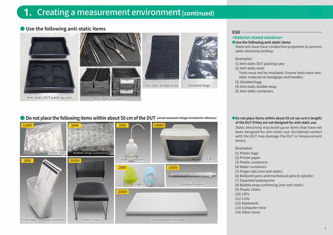
ESD<Material-related solutions>
Use the following anti-static items Materials must have conductive properties to prevent
static electricity buildup.
(Examples)(1) Anti-static DUT packing case(2) Anti-static tools Tools must not be insulated. Ensure tools have anti-
static material on handgrips and handles.(3) Shielded bags(4) Anti-static bubble wrap(5) Anti-static containers
Do not place items within about 50 cm (an arm’s length) of the DUT if they are not designed for anti-static use.
Static electricity may build up on items that have not been designed for anti-static use. Accidental contact with the DUT may damage the DUT or measurement device.
(Examples)(1) Plastic bags(2) Printer paper(3) Plastic containers(4) Water containers(5) Finger cots (non anti-static)(6) Ballpoint pens and mechanical pencils (plastic)(7) Expanded polystyrene(8) Bubble wrap cushioning (non anti-static)(9) Plastic chairs(10) CRTs(11) LCDs(12) Keyboards(13) Computer mice(14) Other items
1. Creating a measurement environment (continued)
Do not place the following items within about 50 cm of the DUT (actual measured voltages included for reference)
Anti-static DUT packing case
Anti-static tools
Anti-static containers
Printer paper and plastic containers Plastic chairs Expanded polystyrene
Finger cots Ballpoint pens
Water containers CRTs
Shielded bagsAnti-static bubble wrap
Plastic bags Bubble wrap cushioning
1200V 500V 350V 10000V
200V
2000V
1000V
280V 5000V
3
Plastic bagsPlastic bags Bubble wrap cushioning
Use the following anti-static items

2. Cautions when placing and connecting the DUT and measuring instrument
Measuring instrument
Power supply DUT test jig
Ionizer
DUT
Staticelectricity
neutralization
Static electricity,potential difference
and alternatingcurrent leakprevention
Groundedpower plug
Groundedconnection
ESD and EOS<Grounded connection>Prevent static electricity buildup by grounding anti-static mats and wrist straps, etc. Before connecting the I/O connectors of measurement devices, or devices connected to those devices (including test circuits), make sure all the devices are connected to a ground cable.
<Grounded power plug>Always connect equipment to ground.
<Power supply>Use a frame ground for grounding.
ESD<Ionizer>Blow ionized air at the DUT and tools to neutralize any static electricity. Ionizers generate ionized air, which carries a charge that electrically neutralizes static electricity.
<DUT>The device under test may also become electrostatically charged. Discharge the static electricity with an ionizer and ground connection.
EOS<DUT>Hot-plugging and powering devices on and off generate transient surge voltages (EOS) that often damage measurement devices. For this reason, check the measurement device and I/O connections in advance according to the EOS check method outlined on page 5.Surge voltages are more likely when performing any of the following operations.(1) Powering on and off(2) Inserting and removing power plug(3) Hot-swapping the DUT(4) Attaching and removing cables(5) During DUT pulse output(6) During DUT probe measurement (including test circuits)
if a operational error causes an electrical short circuit(7) Other operations<Power supply>Use of a chatter-free electronic switch power supply is recommended.
4
FG G

2. Cautions when placing and connecting the DUT and measuring instrument (continued)
Measuring instrument
Power supply PC
DUT test jig
Insertion and removal(hot-plugging)
DUT control(On/Off, settings)
DUTOscilloscope
EOS<EOS check method>(1) Remove the coaxial connector from the I/O connection
on the measurement device, etc., and plug it into the oscilloscope.
(2) Set the oscilloscope input impedance at 50 Ω.
(3) Use single trigger mode and check for a surge voltage.
- The oscilloscope trigger voltage should be approximately +0.5 to +1 V when checking for positive surge voltage. Voltage should be approximately -0.5 to -1 V for improved likelihood of detection when checking for negative surge voltage.
- The time axis will depend on the DUT and testing equipment involved but start at approximately 100 µs/div for improved likelihood of detection.
EOScheck
Surge voltage
5
FG G

3. Solutions
ESD and EOS<J1678A ESD Protection Adapter-K>Use of ESD Protection Adapters with I/O connectors is an effective solution for both ESD and EOS. - Wideband : DC to 40 GHz - Low Insertion Loss : <1.5 dB - Low Reflection : >10 dB - ESD Immunity : 1.8 kV - I/O Interface : K-connector - Small Package : 18×9.5×8 mm - RoHS Compliant
<J1627A GND connection cable>Use of GND Connection Cables between the ground terminals of measurement devices and the device to be measured (including test circuits) is recommended. - Connector : Banana plug/Electrical clip
<41KC- x FIXED ATTENUATOR>Use of attenuators for I/O connections will dampen over-voltage associated with any signal level margin. However, if the over-voltage cannot be attenuated and inputs/outputs exceed the rated voltage, damage may occur. - Wideband : DC to 40 GHz - I/O Interface : K-connector
ESD<G0342A ESD DISCHARGER>The coaxial cable external conductor and core may act as a capacitor and build up an electrostatic charge. Before use, discharge the cable by touching the coaxial cable core to the center of the ESD Discharger. - Connector : SMA / K and V
EOS<K261 DC BLOCK>Use of DC blocks is an effective solution for preventing direct currents. However, they are not very effective for preventing transmission of a steep surge voltage. - Wideband : 10 kHz to 40 GHz - Low Insertion Loss : < 1 dB typical - I/O Interface : K-connector
J1678AESD Protection Adapter-K
J1627AGND connection cable
41KC-xFIXED ATTENUATOR
G0342AESD DISCHARGER
K261DC BLOCK
6

EOS examples
EOSExamples of EOS events<Example 1>I n s e r t i n g / r e m o v i n g D C co n n e c t o r j a c k s a n d hot-swapping DUTsA Test System (XFP/SFP) generated an abnormal surge voltage (above the rated voltage of the measurement device).
Solution - Switch the power supply on and off instead of
inserting and removing the DC connector jack. Change the hot-swapping procedure as well.
<Example 2>Using toggle switches for powering on and offA Test System (SFP) generated an abnormal surge voltage (above the rated voltage of the measurement device).
Solution - Switch the power supply on and off instead of using a
toggle switch.
<Example 3>Dangers of using Bias-T devicesWhen powering a DUT from a Bias-T coil and using a probe to test the signal and ground, accidentally connected the probe signal to ground, which opened the circuit (removed while power supplied) and bounced the power stored in the coil back to the measurement device as a high voltage.
Solution - Take care to avoid short circuits when using a probe,
etc. for debugging. - Do not insert or remove connectors when DC voltage is
being supplied. - Switch the DC power supply on or off after all
connections have been made.
<Example 1> Inserting/removing DC connector jacks and hot-swapping DUTs
<Example 2> Using toggle switches for powering on and off
Inserting and removing the DC connector jack to power the DUT on and off generated a surge voltage (fig. 1).
Using a toggle switch to power the DUT on and off generated a surge voltage (right).
Switching between Open and Short or between Open and 50 Ω generated a surge voltage (right).
Hot-swapping the DUT generated a surge voltage (fig. 2).
>6V
>6V
>10V
PPG ED
IN OUT
PowerSupply
SFP/XFP
Measuring instrument
Inserting/removing DC connector jack to power DUT on/off Hot-swapping DUT
fig.1 fig.2
SFP
PPG ED
IN OUT
DC PowerSupply
Toggleswitch
+3.3VDC Toggle switch topower DUT on/off
>10Vpp
<Example 3> Dangers of using Bias-T devices① Open to Short ② Short to Open
③ Open to 50Ω ④ 50Ω to Open
Measuring instrument
Bias-T Switch50ΩGND
-5 VDCSupply
7
Measuring instrument
Measuring instrumentMeasuring instrument

EOS examples (continued)
EOSExamples of EOS events<Example 4>Alternating current leaks from DUTAlternating current leaked (over-voltage) when the CDR module was not connected to ground.
Solution - Connect the CDR module to ground to avoid over-
voltage output from the module.
<Example 5>Not grounding power outletsAlternating current leaked from a device connected to a power outlet when the work area power outlet ground line was not connected.
Solution - Connect the work area power outlet ground line.
<Example 6>Not frame grounding power suppliesThe power supply was not frame grounded, so the DUT connected to the power supply was not connected to ground, which caused an alternating current leak from the connected device.
Solution - Connect the power supply frame ground to be used as
the power supply ground.
<Example 4> Alternating current leaks from DUT
<Example 5> Not grounding power outlets
CDR modules generated the following voltage.
Alternating current leaked when the power outlet ground line was not connected.
Powering the DUT on and off when the device was not connected to ground generated the following surge voltage.<Example 6> Not frame grounding power supplies
Measuring instrument
AC/DCadapter CLK Out Trigger In
Optical SignalSource
DUT (CDR)
Measuring instrument
Grounded connection
Ungrounded connection
CDR
SMA connector0V (GND)
SMA connectorAC 98 Vrms (AC Leak)
AC: 98 VrmsAC: 98 Vrms
Working Table
<After>
Working Table
<Before>
<After><Before>
Ground Line Ground Line
GND DUT GNDGND
FG G FG G
DUT GND
2.3V
Additional ground cable
Not frame grounding power supply : Surge voltage
8
MAX=DC20Vpp
+2.3V
Applied Period=13 ms
FG G