meccanica bicicletta bicycle mechanics
DESCRIPTION
Meccanica bicicletta bicycle mechanicsTRANSCRIPT

20thANNIVERSARY
SUTHERLAND'S
HANDBOOK FORBICYCLE MECHANICS
Sixth EditionSUTHERLAND PUBLICATIONS

SUTHERLAND'S
HANDBOOK FORBICYCLE MECHANICS
Sixth EditionSUTHERLAND PUBLICATIONS
Howard Sutherland, Leigh Moorhouse, Mark Huie, John S. Allen,Leonard Rubin, Don Milberger, Ed Colaianni, John Porter Hart
Illustrations—Melanie M. Lewallen, Joe Shoulack, Alison Sosna,Fredda Cassidy, Carlos Chaves, Susan Feichtmeir, Tim Keenan,Carol Loverde, Leigh Moorhouse, Mark Schroeder, Nancy Sutherland

Library of Congress Catalublication Data
Sutherland, Howard , 1948-Handbook for bicycle mechanics]
Sutherland's handbook for bicycle mechanics/Howard Sutherland ..let et al] : drawings, Melanie I ewallen, Joe Shoulack .. [et al,]. —6th ed.p. cm.Includes index.ISBN 0-914578-09-X1. Bicycles—Maintenance and repair—Handbooks, manuals, etc.
1. Title. IL Title: Handbook for bicycle mechanics.T1430.595 1995629.28'772—dc2O 95-000459
CIP
Library of Congress Card Number 95-000459Copyright © 1974, 1976, 1981, 1985, 1990, 1995 by Howard Sutherland
Sutherland PublicationsBox 9061, Berkeley, California 94709AlI Rights Reserved

INTRODUCTION
T he sixth edition of Sutherland's Handbook for Bicycle Mechanics is a vital resource for people in the bicycle industry as well as for enthusiasts. Many sources, considerable trav-
eling, measuring, and studying all contributed to gathering the details that make the informa-tion contained here so valuable. Bike'alog, the computer database of parts, was used at everystage of research. Most of the data in this handbook can not he found anywhere else.
Mountain bikes have, in the years since the last edition, become the major category of bicycles.Front suspension is covered here for the first time. And, throughout this edition, we added infor-mation to reflect the enormous number of new components available. The spoke lengths chap-ter has always been an important part of this handbook. Therefore, along with adding all the newri ms and hubs we could get, we revised the layout to make it easier to find the right lengths.
As new rims and hubs are produced far more frequently than we can revise this book, we wanteda quicker way to supply new information to our customers. Through SpokeMaster, a computerprogram for calculating spoke lengths which is distributed with Bike'alog, we are now able torapidly convey information. Every month that we have new rim and huh data, we supply thelistings to Bike'alog who add them to SpokeMaster. We are exploring more ways to distribute thedata in this book via computer.
Leigh Moorhouse has been the driving force behind this edition of the Handbook. The newlydesigned page layout with two colors are just some of the more visible contributions she hasmade. Incorporating insights gained from hike shop experience, printing and graphic produc-tion, she made sure that the information in the book is more accessible. This book wouldn'tbe here without her. Leigh also hired Mark I Huie . Fresh from Avenue Cyclery in San Franciscoand using his extensive hands-on knowledge of the industry as well as his conceptual grasp ofbicycle parts, Mark wrote insightful and accurate descriptions of new bicycle parts and theirrepairs. And as if that weren't enough, Leigh and Mark willingly dove into piles of catalogs andreams of paper to extract the key bits of information that help mechanics get the job done.
John S. Allen has the remarkable ability to picture in his head how a very complex piece of equip-ment works and then write clearly about it. The 7-speed internal hub chapter illustrates this gift andwe all appreciate his work.
Ron Sutfin of United Bicycle Institute has made his resources available whenever we needed them.He opened up the beautifully equipped shop at United Bicycle Institute to me, where I researchedthe previous edition. I am deeply grateful for his help and expertise.
John Barnett of Barnett's Bicycle Institute, once again, generously supplied detailed suggestions fori mproving the hook. He knows, sometimes better than we do, what is needed. His book, Barnett'sManual - Analysis and Procedures for Bicycle Mechanics, is a valuable companion to this one.
Most importantly, I want to thank Nancy, my wife, for keeping the home fires burning whileI was so engrossed in producing this edition of the Handbook.
In previous editions, prepaid reply cards were included to encourage readers' suggestions andcomments. I incorporated as many of the past suggestions as I could, and certainly appreciate allthe ideas I received. In this edition, I am again including prepaid reply cards and I look forwardto hearing from anyone with suggestions for improving the Handbook . Questions and comments
are always welcome.
I suggest you buy two copies of Sutherland's Handbook, one for the shop area and one for theorder desk. You will probably he referring to them often. Many shops buy additional copies toresell to enthusiasts. Take some time to thumb through the hook and become familiar with it.I know you will find it useful.
Howard Sutherland, April 1995
SUTHERLAND'S

With thanks to the following people and organizations:My father, William H. Sutherland, my mother, Betsy Sutherland and special thanks to my wife,Nancy Linn Sutherland, and children, Kory and Andrew Sutherland.
A Bicycle Odyssey, SausalitoAlbert EisentrautAlesa, BelgiumAlison SosnaAmber Cycle SportsAndy NilonAngle Lake Cyclery, SeattleAraya, JapanAriel Trading CompanyAshby Avenue Bike Doctor, BerkeleyAshland Cycle SportAy Caramba BurritosBerkeley CycleBernie SmithBernie Wuthrich -
VVeinmann Sports, Inc.Beverly AndersonBicycle Exchange, CambridgeBicycle Parts PacificBicycle Repair Collective, CambridgeBicycle Technologies InternationalBike'alogBill HomerBontrager CyclesBranciforte Bicycles, Santa CruzBrian GriegerBrian WilliamsCalifornia Bike & Board, DanvilleCampagnolo, ItalyCampagnolo, USACarol BakerCarol LoverdeChang StarChevy Chase Bicycle ShopChris AllenChris LewisConrad OhoCorso Distributing, Inc.Dale SmithDan ColeDan Smith - Rock ShoxDave Wilson, New ZealandDavid Berstein & Jeff Sussman - TiogaDon MilhergerDoug HootenDoug MillikenDr. Richard Allen - ChiropractorEl Cerrito CycleryEli Silberberger - Shimano AmericaEuro Asia ImportsFaber's, San JoseFat Tire Trading Post, FairfaxFIR, ItalyFrank BertoFred WillkieGary FisherGita Sporting Goods, Ltd.Glenn Reichwald - Campagnolo, USAGrafton Performance
Greg MiddletonGuy-King Cycle GroupHank and Frank's Bicycles, OaklandHi-E EngineeringHillary MaleHoward FeldenkreisHowie CohenInternational Bicycle Center,J&B Importers WestJack Kelly - ZeusJames HargettJane BernardJeff GilmoreJeff Tofler - Fisher Mountain BikesJevelotJim Merz - Specialized BicycleJoe BreezeJohn PorterJohn UtheJosh DeetzKarim Cycles, BerkeleyKarin KollerKathy CampbellKevin MoranKHS Inc.Kip ByersLaquieta CaldwellLarry BrowningLee ChiLee KatzLeigh MoorhouseLinne GravestockLois RosnerLouise LacyMark HuieMarti Sacks - Sun Metal ProductsMavic, FranceMel Pinto ImportsMelanie M. LewallenMerry SalesMichael TellerMike DaSilvaMissing Link Bicycle Shop, BerkeleyNaoto Kosugi - Dia-Compe, Inc.Nationwide Cycleparts Supply Ltd.Olivia PerishOschnerPamela MaesPerformance Bike Shop, San RafaelPete Mason - Berkeley CyclePeter Ubelacker - Magura USA Corp.Phil Wood & Co.Pt. Reyes BikesQuality Bicycle ImportsRichard Goodwin, Mitch Clinton -
MavicRichard McKownRick CaldwellRick Comar
Riggio Imports & ExportsRigida, FranceRitchey, U.S.A.Riteway ProductsRuby WilesRuss Okawa - Sachs BicycleComponentsSachs-Huret, Inc.Sal Corso - Stuyvesant BicycleSam Rick's, OaklandSam Patterson - SRAM Corp. (Grip Shift)Seattle Bicycle SupplySharp Bicycles, RichmondShaw's Lightweight Bicycles, Santa ClaraShimano, USAShook-Kingsberry Corp.
(American Classic)Silverio PerezSiskiyou CyclerySkip GathmanSolano CyclerySteve BrownSusan McCallisterTen Speed Drive ImportsThe Components CompanyThe Square Wheel, BerkeleyThorsten SchaetteTim SnyderTodson, Inc.Toni RuthToni WarnerTrek Bicycle Corp. (Matrix)Troxel WestTye Gribb - Klein Bicycle CorporationUnited Bicycle InstituteVelo-Sport, BerkeleyVirginia VillaniWayne CampbellWest, Duke Spinelli & Eric ChavezWestern States ImportsWheelsmith FabricationsWilderness Trail BikesWilliam Clauson - Bikelab (Hugi )Winkel WheelWinning Wheels Bicycle Shop,
Pacific GroveWolber, FranceZAR, International (FIR)
and Jerry Mathis -Collins-Phillips Tool Corporation,Escondido, CA(for producing a custom vernierperimeter tape that made possiblemuch more accurate rimmeasurement)
and everyone who wrote to uswith suggestions.
SUTHERLAND'S

INDEXING
ChecklistAdjustmentsAbout Index ShiftingCable Casing and Casing StopsBrazed-on Lever BossesFreewheel Drop-out SpacingChain RecommendationsTroubleshooting Chart
CAMPAGNOLO, SACHS
7 SHIMANO
SUN TO UR
O THER MAKES
S
6
89
FREEWHEELS,FREEH UB,FIXED G EARS
Hub ShellFreewheelsFreehubs - Cassette CogsMulti-speed FreewheelsSprocket Interchangeability
ChartsCassette Bodies
4
CONTENTS
HOW TO USETHIS BOOK
ContentsBicycle Manufacturers ListSymbolsThread MeasuringNationality of PartsStandardsMaterialsCutting OperationsFits and TolerancesBearingsDrop-outsHand Tools
PEDALS,CLEATS,SHOES
Ball and Thread SizesMarkingsToe Clip BoltsShoe CompatibilityClipless Pedal CompatibilityShoe Size Conversion ChartUniversal Adapters
CRANKS,CHAINRINGS,CHAIN
Cotterless Crank SpindlesCrank ExtractorsCotterless Crank InstallationFit Between Crank and SpindleTaper Angles, Ends & LengthsCrank Arm ProfilesChainring Bolts and SpacersChainring SpacingChainring InterchangeabilityChainring AdaptersChainsCrank Cotters
10
BOTTOM BRACKETS
Ball and Thread SizesCup MarkingsCup-Spindle CompatibilityShell WidthsInterchangeabilityIls
Spindle OnlyComplete SetsCampagnolo
Cartridge BearingSpindlesUnitsPressed BearingDesign Elements
English & French CotterecThompson (Thun)One Piece Ashtabula
SUTHERLAND'S
3

10 HUBS
CONTENTS
SPOKE LENGTHS TIRES1211Ball SizesCone Wrench Size GuideFront Hub and Axle ChartRear Hub DimensionsChainlinesFreewheel ClearanceRear Hub and Axle ChartAbout Cartridge BearingsCartridge SizesCompatibility ChartAssembly/DisassemblyThread ChasersQuick Release Units
List of Hub ModelsAbout Spoke Length ChartsLarge Flange HubsRadial PatternsSpoke and Nipple DimensionsCalculating Spoke Length
Step 1-Hub Flange DiameterStep 2-Spoke Length ChartsStep 3-Rim Size Corrections
Calculating RimCorrection Factors
Number of Spokes
Tire and Rim TypesTire and Rim FitTire and Rim MarkingsMeasuring Rims and TiresRim Cross SectionsTire and Rim WidthTire Size ChartsTubular Tire SizesValve Hole Sizes
HEADSETS,STEMS,HANDLEBARS
Size StandardsMarkings-ThreadedPress Fit Dimensions
and TolerancesReplacing HeadsetsMixing Parts in StacksSteerer lengthTips and ProblemsThreadless SystemsHeadset Dimensions
and ChartsThreadless System ChartLocknuts ChartO'Ring ChartStem DiametersHandlebar Diameters
SUSPENSION FORKS
About Suspension ForksTypes of ForksTypes of SuspensionGlossaryParts of the ForkDesign Elements-Service NotesTroubleshooting ChartsDown Tube ClearanceTools
FRAMESDiameters
DROP-OUTSGear HangersRear Drop-out ThreadsReplacing Forks
SEAT POSTSSizesClamp Bolt
13 BRAKES 14CantileversU-BrakesRoller-CamsSide-pullCenter-pull/DeltaLeversHydraulicsNon-StandardShoes and PadsStraddle Cables
15
SUTHERLAND'S

CONTENTS
16 INTERNALMULTI-SPEED HUBS
Sachs 5- and 7-speedSchematicHow It WorksParts Compatibility ChartDisassemblyCleaning and LubricationAssemblyGear Table
Sachs 3x7Shimano 7-speed
SchematicHow It WorksDisassemblyCleaning and LubricationAssemblyGear Table
17 APPENDIX 181 INDEX
Markings and Product BrochureAbbreviations Order Forms
[SO Standards Suggestion CardsWire Gauge
Comparison ChartTap Drill SizesWeight ConversionsMillimeters to InchesBicycle parts in six
languagesSpoke Length FormulaGear Ratio FormulaThread StandardsRecommended BooksGear Charts
SUTHERLAND'S

BICYCLE MANUFACTURERS - PARTIAL LISTManufacturer Country Manufac turer Country Manufacturer Country Manufac t urer
A A. Vittoria I . . USA Anna . Italy George Stratton , Great Britain Look.A. Singer . .France Ciocc ..Italy Giant . .. Taiwan LotusA.D. Storer, USA City Road Great Britain Giliott Great Briton LuciferAMF .. USA Clark Kent . ...... USA Glorda na .. .Italy LupoAMP . USA Claude Butler Great Britain Gios .. .Italy LygieAegis . .USA Cleveland Welding Gitane .. .France MKMAction-1n USA Colin Lang . Great Britain USA Gottlrred . .FranceAdams .Canada Coinage .. . ...Italy Graftek-Exxon . . .USA
mhl: rtSpocalu
Al Drysdale . .USA Cotner . , .. Katy Grandis . ,Italy MagneAlan Shorter USA, japan Colson .. . . . .. 115A Green . . Fa.. .USA plain d7tO rAllegro Switzartand Calurnbia . .. USA Grove In novaten .. .USA MaimsAlpinestan Taiwan Columbine CT . , I aiwan, USA MakoAmerican USA Co-motion . , _ _ .. USA Guert rot ti . . Italy MantisAmerican Eagle Japan Concord japan, Korea H. France Argentina MaplewoodArneriran Flyer .USA Condor Great Britain, Mexico Harumbrink , . _USA MannAnswer . . ,USA C.onejo _ .. . „ .. .USA Ham , I owan, USA MarinonlArgos . ,Great Britain Copp. . , .. . Italy Harry Powers . ..USA MarurshiArmstrong . .Crest Britain Cores .. .. . - . .Korea Harry Quinn (real Britain MaserallArrow , . .. .USA Corso . .. .. Italy Hawthorne Great Britain Mari (Alberto)Mira .. , France Counterpoint .. .. . .. , .. USA Hedstrom . USA Masi (Cativo)Maid Italy Coventry Eagle . _ . Great Britain Hercules Great Britain Matturi .. ..Atatannenne . .itety Crescent . . . . ... .Sweden, USA Hatch ins Great Britain McMahonAt lantica . Italy Cross-Trak .. .. . USA Hiawatha , Medici _Asistro-Daimler . Austria Curve . . .. .USA Holchworth Great Britain Melton _ .Autonwato .. France Curtin Holland 8 .. ..USA Metal .. ..Azuki .. . Taiwan, japan DB5 .... .. . ... .. .Norway Holland .1. USA Merman „Balance Taiwan USA Dave Moulton . USA Hooker .. ..USA Mercier .. ..Barracuda . . , Taiwan, USA Dalton .. . _ . , . USA Holly (Huffman) . ,A Great Britain Merida _Basso . Italy, USA Davidson .. . USA Hugh Porter . Great Britain Merlin .. ..
BiTIOVUS .. .Netherlands Dawes . . .. . Great Britain alujasS . .. USA Mere .. ..Bates .. Great Britain Dean . , . , . , _USA Humber . Great Britain Miele ..... ..Battle .. _ . .. . _ . .USA de Gribaldy .. .. ..France Hurloni Great Britain MrkkelsonBeacon , _ .France, USA, Japan OeKert .. .. . Canada Hutch .. . _ _ ..USA Miyata .. . _ ..Benotto . . . Mexico, Italy, Panama Delacroix . ... _ ... . ..France his .. , - USA Monarch ..Benin . , . France, Belgium De Rosa . .. .Italy deer . . . ..Italy Monark ............Bevrlacqua .. . , .. ...... ..Italy Diamond Back .. ..Taiwan, Japan ndian .. I 'LA Great Britain Mondla ..Bra, i. Italy, japan, Taiwan Drake .. .. .Great Britain, India ron Horse .. . . USA Monde ..... ,Bil- Ducheron .. .. .. .. ..France taleega .. Italy MongooseBit . . , Dunelt . „ .Great Britain ton .. lapan MonolithBoa , ., .', ..Great Britain Durango .. . . . ... .USA vet Joh nson USA MontagueBin Ira ger Durlsopp . . .. . Germany versos .. _ USA Montgomery WarnButtecchia . ... .. . Italy Easy Racer .. . , ... _USA C. Penney USA Moots . ..Boulder Easy Rider . . . .. Taiwan C. Higgins (Sears. USA, Austria Morales . .Branca . .. . ..... ..Italy .P. Weinle .. .. , Moser. ..'Breeze .. .. USA Eddy Mercka Italy. Belgium, japan, Rj _ . . .Great Britain Mossberg ..Brew .. . ... ... _ . . USA Great BritainFrance, Switzerland ark Taylor . .Great Britain MotobecaneBridgestone - - - . Japan Eisentraul .. .. .05A aquar .. .Germany Moulton -Brodie . .. .. ... . . . . USA amen . _ • i ,reat Bntain Mountain CycleBrowning . _ _ Belgium Ellis Briggs . .Great Britain am is .. . . LISA Mountain GnatBruce Gordon .. .. USA Ellison . , . , , , . .USA et , japan MI ShastaBruns .. _ . USA Emery Mfg, Co, .. USA eurint . . .France Mundo CycleBSA . , ... ... .. Great Britain Emperor .. .. .. -. Japan Uvela . . .Svvilierland Murray ..Burley Erickson . .. .. .. .USA K HS „ . la pan, Taiwan Nashbar ...Benin . , ..... ... _ . .Switzerland Ernha . ... . . .. .Netherlands Kabuki . . japan Neva CyclesC Hansen . . .. . _ „ USA Evans Products Co. .. .. .USA Kalkhon . .Germany Nishiki . .C Itoh ... ... lapan, Taiwan, Korea Excelsior .. .. . . , ,USA Kenstat . - Taiwan Nobilette . . .CCM .. .. . . Canada F.11 Grubb .. „Great Britain Kent . . Taiwan Norco .. ..
France F.W. Evans .. .. .Greal Britain kessels .Belgium Norman , . -CW .. .. . . USA .USA Kestral . Japan Norman Faytt ..Cal-Facet , . .. ...USA Falcon .. , , Great Britain King . Tarwari Novara .. ..
Calol .. ..Brazil Fat Chance .. .. , . .USA Klein . .. . .. _USA Nuke ProofCamera .. .. Italy Fat City .. .. , . .USA Kobe _ . japan, eking Kong Ochsner ..Campania. . . . . Japan ionic .. Kolo _ .. . 011is . ..Cannandale . .. USA Favorit .. .. Czechoslovakia Krim _ . . .. .USA 0 ImoCarbon Frames . . USA Ferrare , .. .Japan Kuwahara . . . . . . lapan One-OffCarlton . Great Britain Peelle . . . _Belgium La Herne .. L. .Canada OrlyCarnielli .. . . . .. .Italy Tomah . , . . , . .. ..I ta ly LaPierre _ . . . .. _France Otis GuyC asat I . - .. - . .Italy Firestone . . . .. _USA Lambert . .Great Britain Paletti , .Castellon . . .. USA Fisher . , . . .. ..USA La Moore . . .. -USA Pan WorldCavaliri-Milani .. - L - Italy Fish tan Land Shark . . . .. .USA PanasonicLatenave .. . . .France Flandr 0 . L. . _ .Belgium Legacy . . .. . . .... . .. Paragon . • .Cato Europa . . ... ... Italy Frier I..' Legn arm .. Italy , Argentina ParkpreCenturion , .japan, Taiwan Feta', .. , .France Lejeune .. _ „ .France PashleyCesare Renato . . . Katy Free '.. . as) L. .. USA, Taiwan Lemond , .. .. Italy, USA Paasoni . .Chaplair . .. .. France Freddie ... .. ..... Liberia . .. . .. . ..France Pennine CyclesChater Lea _ .. .. Great Britain Frejus .. .. . . . Italy Lighthouse .. . . .USA FertOrManCeCherry , . .. .. . .USA Fuji - . , .Japan. Taiwan Lightning .. . , . .USA Peter Mooney ..Chlorda ... _ .. .. . . Litaly Funk .. USA Limited .. .. .1.1SA. Peugeot .. .Chris Chance _ . . . . . .USA G. Genet . .. .. .France Linear . . .. .. .. USA Phillips . . _ .Cignal ..... . . . . Taiwan Galmozzi .. .. L. .. Italy Dopy . . USA Picchio . - -Cao .. .. . . Switzerland Garlatti .. .. .. Italy trtespeed .. . .. .USA Pierce Arrow ..Cinelll . , . ... .. ,
- - Italy Geohrey Butler .. , Great Britain Lryang .. . .. . . Taiwan Pinarelto
Country Manufacturer Country Manufacturer Country
.France Pinto .. France Spectra . _ USA
..Japan Piscean . / anNa ...USA.Switzerland Pluto .Belglum
sSpepeffictrweumn...mat Britain
.. .Italy Plume Vainguei II . Belgium Starno rd .. France.. ....Italy Pogliegth .. ..Italy Steelman .USA.Great Britain Powercurve ..Taiwan Stelber Cycle Gnu . .LISA
..... Taiwan Presto . . . Netherlands Stella .. , .FranceTaiwan, USA Prollex ..Taiwan Sterling . ..ChinaNetherlands
.BelgiumProtein . .. LISAPuch . .Austria
Stevenson . ,Steyr .. .
USA.Austna
....Italy Quantum .. . .. LISA St i nsmen USAjapan Quattro Assi _ . . Italy Stowe .USA
. •USA Raleigh Great Bmainaispan Strawberry . USA
..USA . - Holland, US.A.Tawan Suburban Machin, i . ..USA..USA Ralph Ray _ _ . USA Such ia .japan
Canada Rambler . , .USA Supeha Belgium,lapan Rampar - .. .Taiwan Sutter . . .France
Italy Ranger USA. Great Britain Swiss Army •',..vitzerland..ltaly Rans . . . . USA Sync ros . Canada
.USA Rapido ..Czechosloyakia Sycip ... .. ..USA.japan Railer . . Italy T. M. Cycles .. ..
.USA Rebike . . ..USA Takara .... _japan,USA Redline .. USA Tech . , . . ..USA Regina Sport .France Teledyne Titan . .. USA
,France Rene Heise trance Terrot . . .._France,neat Britain RenshoiCyclonP .Japan Terry ............... t ISA, Taiwan, japan
. .Franc a Research Dynamics .. 1 awan Terry GrimesTaiwan RetroTec .. Thruster ... Taiwan, China
,ieal Britain REW Reynolds .Great Britain TI Cycles .. ..USADV, Rhygin . _ .. Ti-Cranium .. .. . USA
Canada Rickert ...Germany Tigra - .Switzerland.USA Rigi . . ...Italy Titan .. ISA
..Japan RIH . ..Netherlands Titus . .. USASweden Ritchey .. . ....USA Tommasinl . . taly
. .Brat it Roadmaster . . ...USA TOMM.3,0 . . taly'S witzerland Robert Meyers ...._USA Torelli . taly..Germany Roberts . . Great Britain Torpedo , . taly
..USA, Taiwan Robin Hood Great lintain Torque Titanium . ISAUSA
TaiwanRock Lobster „Rocky Mountain ...USA
Trek ,Trimble , .. •
ISAISA
i`i.a.. Japan, Taiwan Rodriguez Triumph 1, di . .1 I RetainRollfast . ...USA Turner Suspension USA
,USA Ramie . . . , .USA Umberto Del .. ItalyMaly Ron Cooper . , .Great Britain Unit'. Sport ..France, Belgium
.. ..USA Ron KI tchi mg . .Great Britain Unikap . ..Netherlands,France, Taiwan Rosignolll . .. Italy Univega .. japan, Taiwan, Italy
.Great Britain Ross , ,USA Urago „ ,.FranceUSA Rosen ..... . ..Italy Vainguesir .. .InaernburgUSA Royal Crown Great Braalis Ventana . ,LISAUSA Royal Enfield .Great Britain Ventura , Taiwan
Brazil Royce Union Italy, Japan Victor . . .USA. USA Budge . . Great Britain Viking .. .G real Britain
USA Ryan , . ..USA Vizier . .. .. .I taly.USA 5.1., Systems .. Viscount , .Great Britain
japanUSA
SR ..japanSaint Tropez .. . Taiwan
Vista ,.Vita Sprint .
.. .USA..France
Canada Salsa .. _USA Voliscycle japanGhat BritainGreat Britam
Samurai . .. . . japanSanta Cruz Mtn Bikes .USA
Vulcan ..Waterford
.Great Britain. _ ,USA
_ Taiwan
.Switzerland
Santana ...Schauff . , .GermanySchroeder L. .. . _ _Denmark
Western AutoWheeler . .Wilderness Trail Bikes
. .USATaiwan
.. . USAFrance Schwartz . . .. .Switzerland Windsor -Great Britain
..Italy St hwinn - USA. lapan, Taiwan Windsor .. . Meeico. USA Manutacturer . .. ....0oun t ry Witcomb . Great Britain
.France. . USA.. Racy
Scull.. USA
Sears . USA, Aintria,Chinaf raneeSek @I . . . . . japan, Taiwan
Wojcik .WoodrupWorksman
. „ ,USA.Great Britain
.. USA.Belgium Senator . "apart Wynn . . .USA
japan Sentinel . . USA Yale .. .USA.. USA Saran a . .USA Yamaguchi ... .LISATaiwan Shelby Flyer .. . . , USA Yeti . .. USA
ran Britain Shimano (pre-1954i .japan Yokota . .. japan.Italy Shogun _ . .japan Zebrakenko Japan
,,rant Britain Si month in I ..Italy Zephyr .....USA
.USASingele . ItalySkyway ..USA
Zeus . .Zinn . .
. . . Spain.USA
.Francerear Britain
Slingshot ....USASoftride ..LISA
Zipp . USA
. .Italy.. .USA
Soles ..... , _ .FranceSoma ,Japan
...Italy Soutlsem Gems .. Great Britain

CONTENTS
HOW TO USETHIS BOOK
How the Handbook is organized.The chapters in this handbook are organized beginning at the pedals where the force is applied
by the rider and continuing chapter by chapter to follow the force as it moves through the
bicycle. This means that parts that work together are close to each other in the book. The pedals
are attached to the crank, the crank is attached to the bottom bracket, and so on. Understanding
that this is the order the chapters are in will also help you find your way around the book.
A contents page is at the beginning of each chapter. This contents page gives an overview of what
is in the chapter as well as directions to find related items that may be found in other chapters.
The Appendix contains ISO standards, torque settings, conversion charts, as well as formu-
las, an index, and gearing charts.
0
Symbols .......................... 2
Ball sizes ............................. 2
Thread sizes ........................ 2
Helpful information ........... 2
Part identification ............. 2
Thread Measuring ...... 1
Example ............................. 2
Nationality of Parts 3
Country .............................. 3
Standard used ................... 3
Standards ...................... 3-4
About .................................. 3
National ............................. 4
De facto .............................. 4
ISO ...................................... 4
Materials ............................... 5
Exotic materials ...............................
Heat treating ..................................
Work hardening .............................
Annealing ........................................
Cutting Operations ............
Tool steel ...................................... 6-7
Lubrication and cooling ..............
Sharpening ......................................
Drilling ..............................................
Thread cutting ............................ 7-8
Thread chasing ..............................
Milling and reaming ....................
Grinding ...........................................
Filing and sawing ...........................
Fits and Tolerances ............ 9Bearings ................................ 9
Bearing design .................................
Cartridge or sealed .................... 1(
Bearing Mountings .......... 10
Drop-outs ........................... 10
Hubs ................................................ 11
Head tube ..................................... 11
Steerer tube .................................. 12
Fork crown .................................... 12
Bottom bracket ............................ 13
Conclusion .................................... 13
Illustrations .................................... 14
Hand Tools ............................ 15About .............................................. 15
Wrenches ...................................... 15
Screwdrivers ................................. 15
Pliers ................................................ 15
Hammers ....................................... 15
Miscellaneous ............................... 15
Specialty bicycle tools ......... 15-16
Suspension Tools ........................ 16
SUTHERLAND'S

Correct
Incorrect
Figure B
HOW TO USE THIS BOOK
I D
SYMBOLSThese symbols will he used to help you find the information you are looking for.
Ball Sizes
Thread Sizes
Things to watch for; helpful information
The easiest way to identify a part
THREAD MEASURING
Example: 9/16" x 20 TPIThe first number refers to the nominal diameter of the male part. When actually measured, as inFigure A, it is frequently slightl y undersize. The second number refers to the Number of
Threads per inch (TPI) or the number of millimeters per thread as measured in Figure B
with a thread pitch gauge. Threads must be clean when measuring. Any rocking motion backand forth indicates an incorrect match.
In the past, the angle that threads were cut led to confusion. (See Thread Standards in theAppendix.) In modern bicycles this is not a problem.
SUTHERLAND'S

HOW TO USE THIS BOOK
NATIONALITY OF PARTSParts will he listed as English, French, Italian, Swiss, U.S., or Austrian to show the standard used
in cutting the thread or the size of the parl. Manufacturers, however, do not always use theirnational standard and different sizes are used instead. For this reason, Raleigh and Schwinn will
be given their own categories in the chart below.
Country of origin does not necessarily indicate the national standard for a part. For instance,
French bicycles that were exported to the U.S. on a large scale used English freewheel threads (BSC).
COUNTRY STANDARD USED COUNTRY STANDARD USED
Australia English Japan English. JIS, U.S.3
Austria English, Austrian Mexico Italian
Belgium English, some French Netherlands English
Canada English Norway English
Denmark English Raleigh English unless listed separately
Great Britain English1Schwinn English unless listed separately
Finland English Sweden English
France 2 French (old) – English or Switzerland French unless listed separatelyISO is current
Germany English Taiwan English
India English United States U.S., English
Italy Italian
1 Please note exceptions under Bottom Brackets and Headsets Chapters.
2 Used Swiss standard in bottom bracket briefly in late 1970's through early 1980's.
3 The Japan Industrial Standard(JlS) is based on the English standard(BSC). Where JIS is
different or no English standard exists we will point out the JIS standard. Japanese bikes
imported to the United States are either U.S. standard or English standard. Generally, if it has an
Ashtabula (one-piece) crank, it is U.S. standard; if it has a three-piece crank, it is English standard.
STANDARDSConfusion over thread sizes and interchangeability of parts used to be far worse than it istoday. For example, matching bottom bracket threads on modern bicycles is not the problemit once was. However, when working on older hikes, it is important to know a little of the his-
tory of standards so problems can be avoided.
SUTHERLAND'S

HOW TO USE THIS BOOK
STANDARDS (CONT'D)National StandardsIn tact, there are standards. But there are so many of them. Back when American bicycles weresold in the U.S., French bicycles in France, Italian bicycles in Italy, and English bicycles mosteverywhere else . . . national standards worked most of the time. In the early 1970's, thedemand for high-quality lightweight bicycles brought bicycles from all over the world to theU.S., and this is when the confusion began.
Currently, there is the Japan Industrial Standard or JIS. Since many of today's Asian compo-nents conic from Japan or did until recently, they are made to JIS standard. Many of the JISstandards are based on the English standard so when there is no JIS standard listed in thishook, refer to the English standard.
De Facto StandardsIn addition to national and international standards, there are de facto standards. Sizes forman y BMX bikes, for example, are based on the Schwinn sizes because when BMX first began,
Schwinn components were the most durable. The marketplace determined the standard. Asimilar situation used to exist for the high-quality road hike market. Because Campagnolo hasbeen used by elite riders for years, a company making parts for this market has needed to
make them interchangeable with "Campy." This led to a Campagnolo standard.
A third de facto standard now exists in drive train components: the Shimano standard.
International StandardsManufacturers, distributors, and cyclists from various countries met in Geneva over a periodof years and came up with standards for the International Standards Organization (ISO).
The ISO is an international agency, a meeting ground for representatives of national standardsorganizations such as the U.S. American National Standards Institute. [he ISO attempts to stan-
dardize dimensions, markings, and safety requirements to increase compatibility, help interna-tional trade, and reduce product hazards. Standards are introduced slowly to avoid disruptionsin trade.
The ISO tries to make new, standardized equipment work as often as possible with existingequipment. For this reason, despite t he trend elsewhere towards metric standards, many of theISO bicycle standards are based on English measurements. ISO thread form is slightly differentFrom English, but parts are still compatible. Axle threads, wrench flats, and the like, whichrequire the use of standard tools in manufacturing or servicing, are metric in the new ISO stan-dards.
Throughout this edition, we have included the ISO standards along with the various nationalstandards. In addition, more detailed specifications are included in the Appendix.
To stun up, standards exist; although they are never as comprehensive as we would like them
to be, having different sets of standards is better than not having any standards at all.
SUTHERLAND'S

HOW TO USE THIS BOOK
MATERIALSWorking on bicycles requires some basic knowledge of metals and their characteristics. Contrary
to the current use of the word in the bicycle trade, alloy does not mean aluminum, but ratherindicates a mixture of metals. An alloy is generally a base metal such as steel or aluminum with
relatively small percentages of alloying metals that impart desired characteristics to the base metal;
these include strength, hardness, wear resistance, machinability, and corrosion resistance. Thecharacteristics of a metal can be changed further by heat treating and/or work hardening.
Aluminum: Pure aluminum is a soft, weak metal with very good corrosion resistance. To be usedfor bicycle parts, it is alloyed with other metals to increase its strength and make it heat treatable.As this alloying degrades the corrosion resistance, most aluminum parts are anodized to protect
against corrosion. Generally this coating is clear, although black and other colors are used.
Steel: The most common steel used on bicycles is carbon steel, which ranges in carbon contentfrom a few tenths of a percent in some frame tubes to about one percent in springs. Generally,
the higher the carbon content, the stronger the steel. By adding small amounts of other metals
such as chromium, molybdenum, or manganese, much stronger steel can he produced. These
alloys are generally found in higher quality frame tubes.
Exotic MaterialsMost of the exotic materials bicycle frames are made with require very skilled labor, often in spe-
cial environments. These frames need only minimal preparation at the shop.
Titanium: Pure titanium is a light, flexible metal. For bicycle use, it is alloyed with other met-
als, usually aluminum and vanadium, to increase its strength and durability. This alloying also
increases the hardness of the metal, making it more difficult to work with. When working withtitanium, you will need to have your tools sharpened often.
Carbon Fiber: Carbon fiber is made from strands of monocrystalline carbon atoms. It is
strongest in tension; carbon fiber strands can be strengthened in other directions depending on
how the fibers are oriented. Carbon fibers need to be held together in a 'matrix', which is usually
made from resin. Carbon fiber can be weakened by small cuts or holes, the same way a piece of
tough plastic can be torn once a small notch has been cut into it. Leave cutting and drilling to
the manufacturers.
Aermet 100: Though Aermet 100 is a type of steel, it is an especially hard metal. Do notattempt any cutting operations on it. However, Aermet 100 is mostly used for frame tubing
only and not for drop-outs, lugs, or the bottom bracket shell, so conventional cutting methods
and tools can be used except on the tubing itself.
Metal matrix composites are a class of materials and cannot easily be lumped together. Be
careful though, most metal matrix composites have very hard materials added to them that can
dull cutting tools quickly.
. Beryllium dust is extremely toxic. Therefore, beryllium should not be cut, milled, or tapped
except in special environments not generally available to bicycle shops.
SUTHERLAND'S

HOW TO USE THIS BOOK
MATERIALS (CONT'D)
Heat TreatingMost steel can be hardened by a variation of two general techniques: tempering and case hardening.
Tempering: High carbon steel, and many steel and aluminum alloys may be tempered.In this process, the material is heated to a specific temperature and then quenched to harden it.The parts are held at another lower temperature for an appropriate length of time to lower theinternal stresses and draw back the hardness to the desired point. This leaves the part uniformly
hard throughout.
Case Hardening: Case hardening can be used on low carbon steel, which generally can-not be tempered by the process of heat treating. Case hardening loads the surface of the part
with a material, usually carbon, that will allow the surface to become quite hard while leavingthe core unhardened. This is desirable to give a hard-wearing surface and a nonbrittle body. Case
hardening also involves heating and quenching.
Work HardeningAnother method of hardening, sometimes unintentional, is by work hardening. Bending, pound-ing, or manipulating the metal causes it to harden and become more brittle. This can be demon-strated by putting a sharp bend in a piece of wire and then attempting to straighten it. The bent
part obviously has hardened and will not straighten to its original form. This characteristic makes
it difficult to properly straighten a bent fork blade, because the bent section is now harder thanthe unbent section.
AnnealingAnnealing is the process of softening metal by heating it close to its melting point and slowly
cooling. This also helps relieve internal stresses in the metal and allow alloying elements (ori mpurities) to redistribute over a slighter larger volume.
CUTTING OPERATIONSThe tool used to work a material should be significantly harder than the material itself or the
tool will wear quickly and not last very long. Because most tools found in bicycle shops weredesigned for use with steel frames, they may be inadequate for use with harder materials.(Please see Exotic Materials on page 0-5 for notes on titanium, carbon fiber, Aerrnet100, metal matrix composites and beryllium.)
Tool SteelCutting tools that are intended to cut steel are made of a special class of steel called tool steel.Tool steels may be either high carbon or alloy steel. Alloy steels are generally called high-speedsteel, as they retain their edges at the temperature generated by high-speed cutting. Carbon steeltools are less expensive than high-speed steel and are generally quite adequate for thread cutting,reaming, and milling when the job is done by hand. The greater cost of high-speed steel is justi-
fied by increased durability when driven by a power tool. Drill bits for cutting steel should always
SUTHERLAND'S

HOW TO USE THIS BOOK
CUTTING OPERATIONS (CONT'D )be high-speed, as they will surely be used with a power drill. Regardless of the material used, allmetal cutting tools have delicate, brittle cutting edges that are easily damaged by misuse. Manymore cutting tools are broken than worn out. Do not throw them together in a box or a drawer.
Lubrication and CoolingWhen using cutting tools, both the tool and the piece to be cut must be properly lubricated andcooled with cutting oil. Most metal-cutting done on bicycles is in steel or aluminum. For best
results in steel, use a high-sulfur base cutting oil available from hardware stores. It is also ade-quate for aluminum. Motor oil, bicycle oil, WD 40, or yesterday's coffee will not do in a pinch!
You will dull your tools and do an inferior job unless you use the right cutting oil in the right
quantity. Dabbing a little oil somewhere on the tool or work before cutting is a waste of time.
The heat and friction are at the cutting edges. Keep them flooded with cutting oil through-
out the operation.
SharpeningEven under the best conditions, cutting tools get dull. Mechanics throw razor blades away after a
few shaves, but expect a tap to cut steel forever. It will, of course, but only if you get it resharpened
before it gets so dull that it breaks off in a hole. Quality drills, taps, dies, milk, reamers, and the likecan all be resharpened at a fraction of their replacement cost! When the tools don't seem to cut as
cleanly and effortlessly as they did when new, look in the Yellow Pages under "Grinding—Precision
and Production." Most large cities will have at least one shop that can do this type of work.
DrillingProbably the most common metal-cutting operation is drilling. Like other power-cutting opera-tions, it requires eye protection and lubrication. The two lips on the end of the drill do all the
cutting and should be kept flooded with cutting oil. The point between these lips is a small chisel
that does not have a sharp edge and must be forced into the work. When drilling larger-diameter
holes, you will find it much faster and easier to drill a pilot hole equal in size to the chisel edge
on the larger drill. All drills, even when properly sharpened, make a hole larger than the drill bitby a small percentage. When improperly sharpened, this error may become quite large and the
hole may not be round. Drilling with a dull bit causes overheating of the work, the bit, themotor, and the operator. The undue friction can cause the walls of the hole to become work
hardened, which may lead to tap breakage if you attempt to thread the hole.
Thread Cutting1. It is i mportant that the hole or shaft size be appropriate for the tap or die being used. (For
tap drill sizes for common fasteners, see Appendix, page 17-6.)
2. If the tool is required to remove too much material, it will bind and possibly break. If too lit-
tle material is removed, the thread will not be strong enough. In reality, the thread profile isnever as sharp as the drawing on page 17-12. The strength of a thread is not improved signifi-
cantly by exceeding 60% of the theoretical thread height pictured in the drawing.
SUTHERLAND'S

HOW TO USE THIS BOOK
CUTTING OPERATIONS (CONT'D)3. Since all the cutting is done by the first few threads of the tap or die, these edges must be
flooded with cutting oil during the threading operation. Failure to adequately lubricatethese edges will result in rapid dulling of the tool, and torn and ragged threads in the work.
4. When threading, the tool should be reversed periodically to break the chip that is formed by the
cutting edge. When threading a deep, small-diameter hole such as the rear axle adjuster in adrop-out, the tap should be backed out completely and chips removed from the tool to prevent
binding and breaking. When cutting large-diameter fine-pitch threads such as bottom bracketsand steerer tubes, the cutting tool must be accurately aligned wit h the work. A die stock withan accurate guide must be used on steerer tubes and a piloted double tap set must be
used on bottom brackets to assure proper alignment of the bearing races and mini-
mize tool wear or breakage. It is important to use the proper tap handle or die stock androtate evenly with both hands to prevent side thrust, which may result in broken tools andruined work.
Thread ChasingThread chasing is distinct from tapping in that it is not cutting threads, but is reforming dam-
aged threads. Taps and dies designed for cutting threads may be used for this purpose as well ascheaper tools that are adequate only for chasing. While it may seem to be a much easier job, usecare, and flood with cutting oil as in thread cutting. Most bottom bracket "thread chasers" havelittle or no pilot, making it difficult to align the tool with the hole. When chasing right-hand
threaded bottom bracket threads with a pilotless tap, use a lockring threaded onto the tool tohelp judge straightness.
Milling (Facing) and ReamingThe ends of the head tube and bottom bracket must be cut accurately so that they are parallel.Facing assures alignment of the bearing races and freedom from binding. The head tube must
also be reamed so that the pressed bearing races will fit into the head tube properly. Facing andreaming operations are done with special cutters made for the job. As with other cutting opera-tions, the tools must be sharp and well flooded with the proper cutting oil. Do not reverse thecutting direction when reaming or milling as this may cause the cutting edge to chip.
Generally, the face of the tube should be milled until the tool is cutting all the way around thehole.
GrindingGrinding may be used on any steel. It may be used on hardened steel, as normal cutting tools
will not work. Grinding is a hazardous operation, requiring guards, eye protection, and propertechnique. Grinding wheels must be sharpened and formed with a "wheel dresser" to get good
results. Do not attempt to grind nonferrous metals such as aluminum or brass! Use a fileor power sander for these soft metals or they will clog the pores of the grinding wheel.
SUTHERLAND'S
HOW TO USE THIS BOOK
CUTTING OPERATIONS (CONTD)
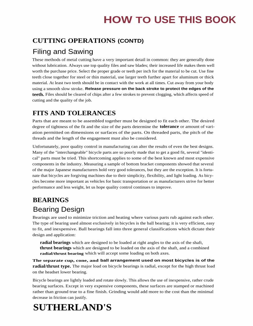
Filing and SawingThese methods of metal cutting have a very important detail in common: they are generally donewithout lubrication. Always use top quality files and saw blades; their increased life makes them well
worth the purchase price. Select the proper grade or teeth per inch for the material to be cut. Use fine
teeth close together for steel or thin material, use larger teeth further apart for aluminum or thickmaterial. At least two teeth should be in contact with the work at all times. Cut away from your body
using a smooth slow stroke. Release pressure on the back stroke to protect the edges of the
teeth. Files should be cleared of chips after a few strokes to prevent clogging, which affects speed of
cutting and the quality of the job.
FITS AND TOLERANCESParts that are meant to be assembled together must be designed to fit each other. The desireddegree of tightness of the fit and the size of the parts determine the tolerance or amount of vari-
ation permitted on dimensions or surfaces of the parts. On threaded parts, the pitch of thethreads and the length of the engagement must also be considered.
Unfortunately, poor quality control in manufacturing can alter the results of even the best designs.
Many of the "interchangeable" bicycle parts are so poorly made that to get a good fit, several "identi-
cal" parts must be tried. This shortcoming applies to some of the best known and most expensive
components in the industry. Measuring a sample of bottom bracket components showed that several
of the major Japanese manufacturers hold very good tolerances, but they are the exception. It is fortu-nate that bicycles are forgiving machines due to their simplicity, flexibility, and light loading. As bicy-
cles become more important as vehicles for basic transportation or as manufacturers strive for better
performance and less weight, let us hope quality control continues to improve.
BEARINGSBearing DesignBearings are used to minimize triction and heating where various parts rub against each other.The type of bearing used almost exclusively in bicycles is the ball bearing; it is very efficient, easy
to fit, and inexpensive. Ball bearings fall into three general classifications which dictate their
design and application:
radial bearings which are designed to be loaded at right angles to the axis of the shaft,thrust bearings which are designed to be loaded on the axis of the shaft, and a combinedradial/thrust bearing which will accept some loading on both axes.
The separate cup, cone, and ball arrangement used on most bicycles is of the
radial/thrust type. The major load on bicycle bearings is radial, except for the high thrust load
on the headset lower bearing.
Bicycle bearings are lightly loaded and rotate slowly. This allows the use of inexpensive, rather crudebearing surfaces. Except in very expensive components, these surfaces are stamped or machinedrather than ground true to a fine finish. Grinding would add more to the cost than the minimal
decrease in friction can justify.
SUTHERLAND'S

Figure 2
Figure 3
HOW TO USE THIS BOOK
BEARINGS (CONT'D)Cartridge or sealed bearings are finding their way into quality bicycle components. Thesebearings, commonly used in industrial applications, have the balls captured between inner andouter races making up a one-piece unit. (ln a normal bicycle bearing, the cups and cones are the
races.) These cartridge bearings are very precisely made and may include felt or plastic seals to
hold in grease and keep out dirt and water, While this type of bearing is vastly superior, it lacksone important virtue that the cup/cone type bearing does have: it will not tolerate nearly as muchmisalignment as the cup/cone bearing can (and must). The thin flexible axle and the narrowspool of a standard bicycle hub cannot hold cartridge bearings in alignment. A larger diameterspool is required to keep the outer races aligned as the rider imposes both radial and thrust loadson the hub flanges. Similarly, the axle inside the hub must be larger in diameter to keep the Innerraces precisely Lined up. Good design can accomplish this without a weight penalty.
BEARING MOUNTINGSDrop-outs— A bearing is no better than its mounting.The smoothness, efficiency, and longevity of bicycle bearings can usually be improved by refining themountings found on the average bicycle frame. For general instructions on reaming, tapping, andmilling (see previous section on cutting operations). Procedures for specific bearings follow.
Figure 1
Figure 1.Drop-out alignment
gauges installedFigure 2.
Drop-out outof alignment
Figure 3.Drop-out aligned
SUTHERLAND'S

HOW TO USE THIS BOOK
BEARING MOUNTINGS (CONT'D)
HubsThe rear drop-outs and fork-ends arc an important part of the wheel bearing mounting. If the
hub is clamped between non-parallel surfaces, the thin axle will bend and misalign the cones.
Drop-out alignment gauges are made by Campagnolo, Park, and VAR to check and correct thealignment and spacing of drop-outs. (See Figures 1, 2, and 3.) These tools are a combinationgauge and lever for bending the drop-outs into alignment. Use these tools to align only steelframes not aluminum or carbon fiber. (NOTE: Most mountain bike and road bike rear drop-
outs must be properly spaced and re-aligned for new 8-speed wheels.)
Head TubeThe headset bearing cups seat in the ends of the head tube. The inside of the tube must be accuratelyreamed for a press fit and the ends of the tube must be milled parallel to align the cups. BicycleResearch Products, Campagnolo, Park Tool, VAR, and Zeus make tools which will do both of these
operations; some head tools also serve as a press to install the cups. As shown (see Figure 4), the
head tool has a T-shaped handle, a flat milling cutter, and a reamer mounted on a threaded rod. Therod is inserted in the head tube, and a centering cone, a spring, and a star nut are installed at theother end of the tube. The nut should be tightened to compress the spring about halfway. Flood thework area with cutting oil and rotate the tool clockwise, looking down on the handle. Do notreverse direction as this may cause the tool steel cutting edges to chip. As the tool turns, the reamer
will go into the tube until the milling cutter contacts the tube face, (see Figure 5). More spring ten-
sion may be needed at this poinL Further rotation will cut the face of the tube at precisely 90° to itsaxis. Continue cutting until there is bright metal all the way around the tube. (It may be necessary to
remove the tool to check this.) After one end of the tube is finished, repeat the procedure for the
other end. After both ends are done, clean the metal chips and cutting oil from the tube. The toolmay be used to press the cups into the head tube. A centering thrust washer is installed between thereamer and the bearing cup, as shown (see Figure 6). The centering cone and spring are not used
in this operation. Make sure the cups start straight, then turn the
handle until they are pressed tight against the tube ends,(see Figure 7).
flat milling cutter
----- reamer
centering cone
spring
-- star nut
Figure 4.
Assembly for milling and reaming head tube
Figure 5
Milling and reaming head tube
SUTHERLAND'S

reamercenteringthrust washer
bearing cups
star nut
Figure 8.Steerer tubethread cutting
Figure 9.Fork crown
race cutting
HOW TO USE THIS BOOK
BEARING MOUNTINGS (CONT'D)
Figure 6. Head cup press assembly Figure 7. Installing head cups with press
Steerer TubeTo assure that the threads on the top of the steerer tube are aligned with the tube axis, the diecutting them must be held in a die stock provided with a suitable guide, (see Figure 8). The top
cone of the headset bearing depends on these threads for its alignment. Campagnolo, Hozan,VAR, and Zeus make the proper tools for this job.
Fork CrownWhere the steerer tube enters the fork crown, the diameter of the tube and the top of the crown
must be machined to accept the headset bottom cone. This job is best done on a lathe, but anacceptable job may be done with a crown race cutter as made by Campagnolo, VAR, or Zeus,as shown (see Figure 9). The tool is slipped over the steerer tube and the spring compressed toapply downward pressure to the hollow cutter. Using a cutting oil, rotate cutter clockwise until itleaves a complete circle of bright metal on the fork crown. Do not reverse direction as this
may cause the cutting edges to chip. Clean the fork and drive the bearing cone in place witha hollow slide hammer or a piece of water pipe.
SUTHERLAND'S

HOW TO USE THIS BOOK
BEARING MOUNTINGS (CONTD)
Bottom BracketThe threads and the face of the bottom bracket shell are the mount for the crank bearing cups.Even if these are accurately machined, they will probably he distorted during the brazing of theframe. Bicycle Research Products, Campagnolo, Park, VAR, and Zeus all make a double tap with
an aligning pilot shaft that may be used to correct or cut these threads. Select the proper taps torthe bottom bracket to be cut. The adjustable cup is always right-handed threading and the fixedcup varies right- or left-handed threading. To be sure if the fixed cup is right- or left-handed
threading, (see Bottom Bracket Chapter page 3-2, Thread Sizes).
Inspect the inside of the bottom bracket shell to make certain that none of the frame tubes
extend into the path of the cutters. If they are in the way, they may damage the taps. Use a file
for the slow and tedious job of removing the unwanted tube ends. Install the taps on the handlesand insert the pilot shaft through the bottom bracket shell and into the hollow handle. (SeeFigure 10 on the following page.) Flood with cutting oil and start both taps into the shell at
the same time, (see Figure 11). Run the taps in until there are enough complete threads to
accept the bearing cups. Remove one tap and replace it with the flat facing mill and aluminum
pilot, as shown (see Figure 12). Insert the handle onto the protruding pilot shaft until the cut-
ter is against the shell. Using cutting oil, press in and turn clockwise (do not reverse) until the
bright metal shows all the way around the end of the shell, (see Figure 13). Repeat on the other
end of the shell, changing taps if required. Clean up chips and oil, including the chips hiding inthe chain stays, and install the bottom bracket.
Since Italian threading is the largest diameter, a bottom bracket shell with stripped or badly dam-
aged threads may be made as good as new by converting to Italian standard threading, unless itwas already Italian thread. Remove the old threads using a Bicycle Research Product BottomBracket reamer on one side of the double tap handle, with a tap matching the threading in the
shell threaded into the other side, as shown (see Figure 14). Using cutting oil, push the reamer
into the shell while turning it clockwise until the old threads are removed. Continue turningclockwise while pulling the reamer out of the shell. Without removing the tap, replace the
reamer with an Italian tap and cut new threads.
Leave the Italian tap in the shell and remove t he other tap. Replace this tap with t he reamer andrepeat the reaming and threading operations. This fast, easy repair saves a ruined frame for the
cost of the bearing cups and twenty minutes work. The old spindle may be used, if serviceable.
I N CONCLUSIONAlways keep in mind that a bearing may only function if it is rigidly and accurately mounted.
The more precise the bearing, the more vulnerable it is to misalignment.
SUTHERLAND'S

HOW TO USE THIS BOOK
BEARING MOUNTINGS(CONT'D)
Figure 10.Installing double-sided tap
with aligning shaft
Figure 11.Starting taps
aluminum pilotfacing mill
Figure 12.Milling assembly
Figure 13.Milling bottom bracket face
Figure 14.Reaming bottom bracket shell
to remove stripped threads
SUTHERLAND'S
HOW TO USE THIS BOOK
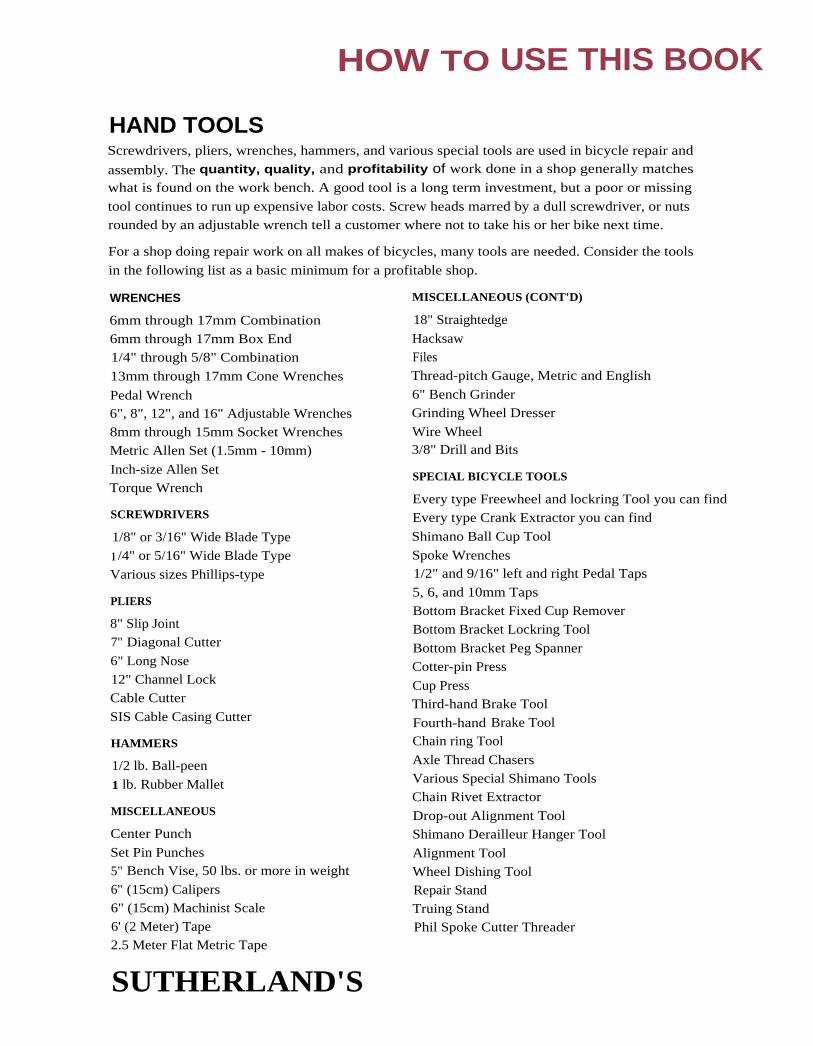
HAND TOOLSScrewdrivers, pliers, wrenches, hammers, and various special tools are used in bicycle repair and
assembly. The quantity, quality, and profitability of work done in a shop generally matches
what is found on the work bench. A good tool is a long term investment, but a poor or missing
tool continues to run up expensive labor costs. Screw heads marred by a dull screwdriver, or nutsrounded by an adjustable wrench tell a customer where not to take his or her bike next time.
For a shop doing repair work on all makes of bicycles, many tools are needed. Consider the tools
in the following list as a basic minimum for a profitable shop.
WRENCHES
6mm through 17mm Combination
6mm through 17mm Box End1/4" through 5/8" Combination
13mm through 17mm Cone Wrenches
Pedal Wrench6", 8", 12", and 16" Adjustable Wrenches
8mm through 15mm Socket WrenchesMetric Allen Set (1.5mm - 10mm)
Inch-size Allen SetTorque Wrench
SCREWDRIVERS
1/8" or 3/16" Wide Blade Type
1 /4" or 5/16" Wide Blade Type
Various sizes Phillips-type
PLIERS
8" Slip Joint7" Diagonal Cutter
6" Long Nose12" Channel LockCable Cutter
SIS Cable Casing Cutter
HAMMERS
1/2 lb. Ball-peen
1 lb. Rubber Mallet
MISCELLANEOUS
Center Punch
Set Pin Punches5" Bench Vise, 50 lbs. or more in weight
6" (15cm) Calipers6" (15cm) Machinist Scale6' (2 Meter) Tape2.5 Meter Flat Metric Tape
SUTHERLAND'S
MISCELLANEOUS (CONT'D)
18" Straightedge
HacksawFiles
Thread-pitch Gauge, Metric and English
6" Bench GrinderGrinding Wheel Dresser
Wire Wheel3/8" Drill and Bits
SPECIAL BICYCLE TOOLS
Every type Freewheel and lockring Tool you can find
Every type Crank Extractor you can find
Shimano Ball Cup Tool
Spoke Wrenches1/2" and 9/16" left and right Pedal Taps
5, 6, and 10mm Taps
Bottom Bracket Fixed Cup Remover
Bottom Bracket Lockring Tool
Bottom Bracket Peg SpannerCotter-pin Press
Cup PressThird-hand Brake Tool
Fourth-hand Brake ToolChain ring Tool
Axle Thread ChasersVarious Special Shimano ToolsChain Rivet Extractor
Drop-out Alignment ToolShimano Derailleur Hanger Tool
Alignment Tool
Wheel Dishing ToolRepair Stand
Truing StandPhil Spoke Cutter Threader

HOW TO USE THIS BOOK
HAND TOOLS (CONT'D)SPECIAL BICYCLE TOOLS-SUSPENSION FORKS
Specialty tools are supplied by the manufacturer in consumer tool kits and the tool designschange annually. Hopefully, the bicycle industry will not need many specialty tools for suspen-
sion forks in the future, as many manufacturers streamline repairs to use basic tools such as sealpullers, snap ring pliers, air pumps, and hands.
1" stanchion vise blocksSeal separator (puller)Snap ring pliersLong 4mm alienLong 5mm al lenLong 6mm alien
Long 8mm alienPhillips screwdriverFork air pump w/needle19mm socket22mm socket
Metric rulerRebuild kitsTeflon-based greaseBlue LoctiteFlat blade screwdriver
ONE LAST WORD ABOUT TOOLS:— Cheap tools are an extravagance no bicycle shop can afford.—
SUTHERLAND'S

CONTENTS
1
Pedals
Ball and retainer sizes ................... 2
Thread sizes ..................................... 2
Markings on wrench flats ........... 2
Markings on crank arms .............. 2
Right & left-handed threads ..... 2
Toe clip bolt - pedal ...................... 2
Compatibility and drilling .......... 4
Clipless pedals chart ................. 5-7
Bolt pattern .......................... 5-7
Release adjustments ............ 5-7
Cleats
Fixed ................................................ 3
Floating ........................................... 3
Parts of clipless system .............. 3
Compatibility and drilling ......... 4
Bolt pattern .................................... 4
Clipless cleats chart ................. 5-7
Cleat adapters .................. 5-7
Shoes
Compatibility and drilling ......... 4
Adapters .......................................... 4
Bolt patterns .................................. 4
MTB conversion chart ............... 4
Drilling .................................. 4
Adapters ................................ 4
Road conversion chart ............... 4
Drilling .................................. 4
Adapters ................................ 4
Shoe size conversion chart ........ 7
Universal adapters ....................... 7
SUTHERLAND'S

Ball and Retainer SizesSealed cart. bearings Bearing no. ID ODSunTour inner pedal 6500 10mm 19mm
SunTour outer pedal 698 5mm 20111mOnza '94 686 6mm 12mmTime 6901 12mm 24mm
Most pedals use 10 to 15 -5/32" per side or 1/8" balls
PEDALS, CLEATS, SHOES
PEDAL-CRANK
ID
ID
ID
Thread Sizes150* Primary 1/2" x 20 TPI Right- and left-handed thread
Alternate 9/16" x 20 TPI Right- and left-handed threadEnglish 9/16" x 20 TPI Right- and left-handed t hreadFrench** 14mm x 1.25mm Right- and left-handed threadItalian 9/16" x 20 TPI Right- and left-handed threadU.S.A. 1/2" x 20 TPI Right- and left-handed thread
Italian threads are slightly different than English and are a tighter fit in English t hreaded cranks.
* See .appendix for more details on ISO standards.** Peugeots and some other french bicycles have used English 9/16" x 20 TPI for the U.S. market
since the mid '70s.
French cranks can easily be tapped to 9/16" x 20 TPI.
When retapping pedal threads, start from the hack of the crank arm.
Markings on Wrench FlatsCampagnolo, others Zeus
English, Italian 9/16" x 20 BSCFrench 14 x 1.25 no mark
Markings on Crank ArmsEuropean Japanese
English 9/16" x 20 no markFrench 14 x 1.25 M14Italian 9/16" x 20
Pedal Codes for Right- and Left-handed ThreadsRight Left
English R LFrench I7 CTItalianSpanish
Toe Clip Bolt — PedalUse 5mm x 0.8mm threads.
SUTHERLAND'S

shoe
PEDALS, CLEATS, SHOES
CLIPLESS PEDALS, CLEATS, AND SHOES
Types of Clipless SystemsFixed CleatThe fixed cleat system keeps the shoe stationary in the pedal.The shoe may be able to twist or slide from side to side, but
there will be a returning or centering force trying to return
the shoe to its original position. It the shoe is moved againstthis centering force beyond a certain position, the cleat and
pedal will disengage. Some older systems needed to be disen-
gaged by hand.
Floating CleatThe floating cleat system allows the shoe to float, or rotate from side to side, in the pedal. Theshoe is able to twist or slide from side to side within a given range, with little or no return force.Outside this range either the pedal and cleat immediately disengage, or the return force progres-
sively increases until the cleat disengages.
Parts of the Clipless SystemCleat - The piece on the shoe that attaches to the pedal; it allows the shoe to latch and unlatch
from the pedal. Cleat adjustment describes adjusting the cleat to the rider's foot over the
pedal. Clipless systems have fore and aft adjustment. In addition, most have side to side and
rotational adjustments.
Pedals - Generally, the clipless systems come with 9/16" threaded axle spindles, two sided pedalswith mounting brackets, or plates for mountain bikes, or single sided pedals for road. The pedal
controls the tension capabilities.
Release Tension Spring - This spring, adjustable on mostpedal systems, controls the tension which releases the cleat
from the pedal. The rider must twist the shoe to one side
which releases the shoe from the pedal.
Adapter plates - These plates allow adaptability from
shoe to pedal. The three main types are: shoe adapter
plates that are made to fit one specific manufacturer'sshoes (usually within the recess in the shoe); cleatadapters that are made to adapt the drilling of one specif-
ic manufacturer's cleat to a different drilling on a shoe;
and universal adapter are plates that adapt one style of
drilling to a different bolt pattern.
SUTHERLAND'S

PEDALS, CLEATS, SHOES
COMPATIBILITY AND DRILLINGShoes and clipless pedals are matched to each other by matching shoe drilling with cleat boltpatterns. Each cleat has one bolt pattern, but cleat adapters can be used to match the cleat to a
different shoe drilling. Shoes can have multiple drilling to match different cleat bolt patterns.
Some shoes have shoe adapter plates to match various cleat bolt patterns. Most cleats have one
of the three primary bolt patterns: 2 hole/SPD, 3 hole/Look, or 4 hole/Time. Other cleats havea unique bolt pattern that matches a shoe made specifically for them. Often these cleats will
come with a cleat adapter plate to match one of the primary shoe drilling.
Bolt patterns Spacing2 Hole/SPD 12mm apart3 Hole/Look 31.5 x 31.5 x 33mm4 Hole/Time 16.5mm wide x 54mm long
There are also shoes with custom drilling unique to the shoe design. These often have recesses
for the shoe adapter plates and the shoe adapter plates may have any one of the three primarydrilling in them.
Example for using the charts: Vittoria shoe to an Onza pedal, look under "Clipless Pedals and
Cleats" on page 1-5, the Onza H.O. cleat has a 2 hole/SPD drilling. Then look below for theShoes - MTB, find the Vittoria shoe; it has a 2 hole bolt pattern. The Vittoria shoes will workwith the Onza pedals and cleats with no adapters needed.
Shoes — MTB
MakeShoeDrilling
Shoe Adapter Platesfor Bolt Patterns
ALPINESTARS 2 Hole/SPD3 Hole/Look
CARNAC Custom 2 Bolt/SPD, Speedplay,Toe Clips
DIADORA 2 Hole/SPD,Custom
DUEGI 2 HOLE/SPD
GAERNE 2 Hole/SPD 3 Bolt/Look, Toe Clips
LAMSON 2 Hole/SPD 1LAKE 2 Hole/SPD
NIKE 2 Hole/SPD
PERFORMANCE 2 Hole/SPD
SCOTT 2 Hole/SPD 3 Bolt/Look
SHIMANO 2 Hole/SPD recessed - none
SIDI Custom 2 Bolt/SPD,3 Bolt/Look, Toe Clips
SPECIALIZED 2 Hole/SPD recessed - none
TIME 4 Hole/Time 2 Bolt/SPD, Speedplay
VITTORIA 2 Hole/SPD3 Hole/Look
3 Bolt/Look2 Bolt/SPD
Shoes — Road
MakeShoeDrilling
Shoe Adapter Platesfor Bolt Patterns
CARNAC Custom Ergo, Speedplay,2 Bolt/SPD, 3 Bolt/Look,4 Bolt/Time
DETTO PIETRO 3 Hole/Look
DIADORA 3 Hole/LookCustom/Ergo 2 Bolt/Time,
4 Bolt/Time
EURO 3 Hole/Look
LAKE 2 Hole/SPD,3 Hole/Look
none
NIKE 2 Hole/SPD3 Hole/Lookand Custom
SHIMANO 2 Hole/SPD,3 Hole/Look
SIDI 3 Hole/Lookand Custom
2 Bolt/SPD, 4 Bolt/Time
SPECIALIZED 3 Hole/LookTIME 4 Hole/Time 3 Bolt/Look, SpeedplayVITTORIA 3 Hole/Look
and CustomErgo, 2 Bolt/SPD,4 Bolt/Time
1 Lamson makes soles to order for 3 Bolt/Look, Speedplay, and Diadora.
SUTHERLAND'S

PEDALS, CLEATS, SHOES
Clipless Pedals and Cleats — MTB
MakePedalModel Cleat
BoltPattern
CleatAdapters Float
ReleaseTension
BEBOP MTB Bebop 2 Bolt/SPD 15° none
GRAFTON all1 Grafton 3 Bolt/Look 10° allen
LOOK S2R and 525MP-908
MicroLook
Black, Red
2 Bolt/SPDCustom
6°fixed,6° flathead
MKS MKS 2 Bolt/SPD fixed alien
ONZA H.O. Onza 2 Bolt/SPD 6°, 10° replace elastomer
RITCHEY Logic,
Logic WCS
Logic 2 Bolt/SPD allen
SHIMANO M525
M737
M323 1,7
M535M747
SM-SH5O
SM-SH55SM-SH51
SM-SH71
SM-SH50
SM-SH55SM-SH51 6
SM-SH70
SM-SH71
2 Bolt/SPD
2 Bolt/SPD
2 Bolt/SPD2 Bolt/SPD
2 Bolt/SPD2 Bolt/SPD2 Bolt/SPD
2 Bolt/SPD
2 Bolt/SPD
fixed
fixed 5
6°6°
2°2°5
12°fixed
12°
allen
allen
SPEEDPLAY Magnum
Frog
SpeedPlay
Frog
2 Bolt/SPD
2 Bolt/SPD56°
2502nonenone
TIME MTB TMT Custom4 2 Hole/SPD 10°3 none
TIOGA Clipman Clipman 2 Bolt/SPD 3° alien
VICTOR VP-101 VP 2 Bolt/SPD alien
1 Standard toe clips can be used on some models.2 25° of heel outward float, 0° inward, cleat can be rotated to adjust the inward and outward
float.3 Cleat also has 10mm of side to side play.4 TMT uses standard 2 Hole/SPD drilling, but the cleat is thicker than standard 2 Hole/SPD cleats.5 Shimano SM-SH55 allows easier release than SM-SH50 .6 This is the recommended cleat for this pedal.7 Shimano tool TL-PD32 is needed to remove the plug on the pedal before a cleat can be used.8 Look MTB is a custom 2 Bolt pattern.
SUTHERLAND'S
PEDALS, CLEATS, SHOES
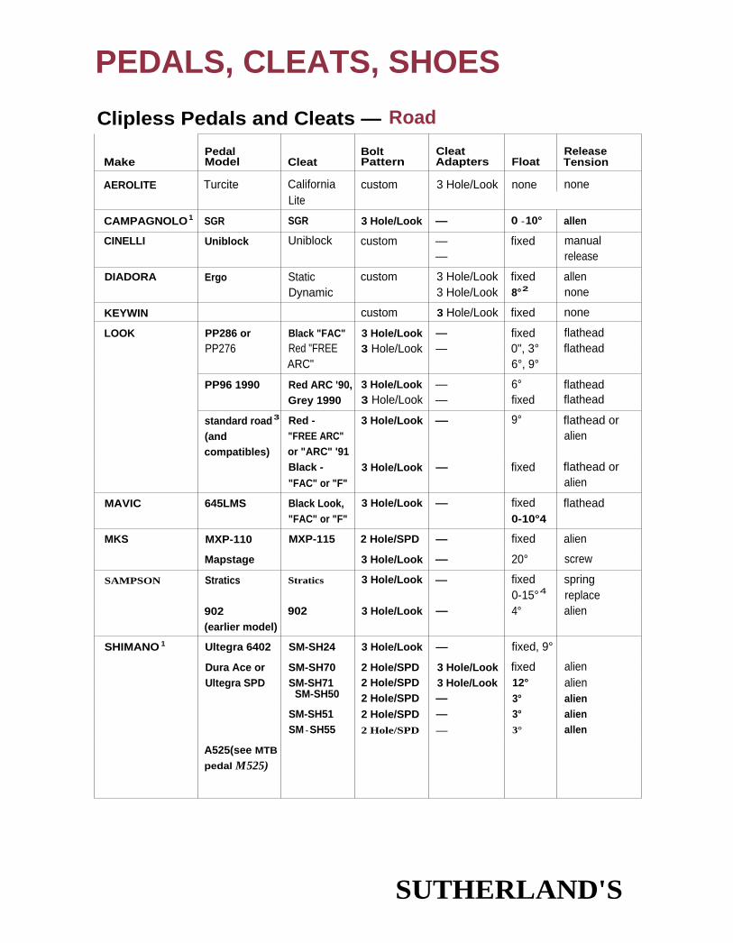
Clipless Pedals and Cleats — Road
Pedal Bolt Cleat ReleaseMake Model Cleat Pattern Adapters Float Tension
AEROLITE Turcite California custom 3 Hole/Look none noneLite
CAMPAGNOLO1 SGR SGR 3 Hole/Look — 0 -10° allen
CINELLI Uniblock Uniblock custom ——
fixed manualrelease
DIADORA Ergo Static custom 3 Hole/Look fixed allenDynamic 3 Hole/Look 8°2 none
KEYWIN custom 3 Hole/Look fixed none
LOOK PP286 or Black "FAC" 3 Hole/Look — fixed flatheadPP276 Red "FREE 3 Hole/Look — 0", 3° flathead
ARC" 6°, 9°
PP96 1990 Red ARC '90,Grey 1990
3 Hole/Look3 Hole/Look
——
6°fixed
flatheadflathead
standard road3
(andcompatibles)
Red -"FREE ARC"or "ARC" '91
3 Hole/Look — 9° flathead oralien
Black -
"FAC" or "F"3 Hole/Look — fixed flathead or
alien
MAVIC 645LMS Black Look,"FAC" or "F"
3 Hole/Look — fixed0-10°4
flathead
MKS MXP-110 MXP-115 2 Hole/SPD — fixed alien
Mapstage 3 Hole/Look — 20° screw
SAMPSON Stratics Stratics 3 Hole/Look — fixed0-15°4
springreplace
902 902 3 Hole/Look — 4° alien(earlier model)
SHIMANO 1 Ultegra 6402 SM-SH24 3 Hole/Look — fixed, 9°
Dura Ace or SM-SH70 2 Hole/SPD 3 Hole/Look fixed alienUltegra SPD SM-SH71 2 Hole/SPD 3 Hole/Look 12° alien
SM-SH50 2 Hole/SPD — 3° alienSM-SH51 2 Hole/SPD — 3° alienSM - SH55 2 Hole/SPD — 3° allen
A525(see MTB
pedal M525)
SUTHERLAND'S

PEDALS, CLEATS, SHOES
Clipless Pedals and Cleats Road (cont'd)
MakePedalModel Cleat
BoltPattern
CleatAdapters Float
ReleaseTension
SPEEDPLAY X/1 or X/2 X-series 3 Hole/Look,4 Hole/Time
Carnac,Nike, Sidi,and Time
+29°-8°5
none
Shoes6
SR FXP-100 FXP-100 3 Hole/Look — 4° alien(See Sampson902)
TIME TBT TBT 4 Hole/Time 3 Hole/Look 10°7 noneTWT TWT custom 10°7 none
1 Also makes Look compatible pedals. See Look standard road.2 Allows 6mm of side to side play.3 Low end models do not have release tension adjustment.4 Play is independently adjustable inward and outward.5 Has 29° of heel outward float and 8° of heel inward float (37° total).6 Proper length screws are available for Carnac, Sidi, and Time shoes.7 Depending on the pedal model, the cleat has 10 to 14mm of side to side play.
Shoe Size Conversion ChartU.S. 4 4.5 5 5.5 6 6.5 7 7.5 8 8.5
European 36.5 37 38 38.5 39.5 40 40.5 41 42 415
U.S. 9 9.5 10 10.5 11 11.5 12 12.5 13
European 43 43.5 44 - 45 45.5 46 47 47.5 48
44.5
CARNAC + ONE SIZE UP
Universal Adapters
Make Shoe drilling Cleat style
Syntace 3 Hole/Look (Look) to 2 Hole/SPD
Thompson none - chip** 3 Hole/Look (with Look cleat)
Winwood none - clip** 2 Hole/SPD (with SPD cleat)3 Hole/Look (with Look cleat)4 Hole/Time (with Time cleat)
** Allows clipless pedals to be used like standard toe clips with street shoes.
SUTHERLAND'S

PEDALS, CLEATS, SHOES
SUTHERLAND'S

ChainCharacteristics
Size ....................................... 20
Number of links ................... 20
Bushings ............................... 21
Chain dimensions ................ 21
Width/Pin length ................. 21
Chain cutting notes ................. 22
CONTENTS
CranksCotterless crank spindles
Bolts and nuts ......................... 2
Thread sizes ............................ 2
Cotterless crank extractors ... .... 2
Installing cotterless cranks ......... 4
Fit between cotterless cranks
and spindles ........................ 4-5
Taper angles ........................ 4-5
Taper end sizes ........................ 5
Taper length notes .................. 6
Crank arm profiles ...................... 7
Crank cotters ............................ 23
ChainringsBolts/spacers chart ................... 8
Rings ..................................... 8
Spacing ................................. 9
Thickness ............................... 9
5-arm chainrings and crankarms
interchangeability ....... 10-16
About adapters .................. 16
Adapter interchangeability .. 17
5-pin chainrings
interchangeability ............ 1 8
6-bolt chainrings
interchangeability ............ 1 8
3-arm chainrings
interchangeability ............ 19
SUTHERLAND'S

CRANKS, CHAINRINGS, CHAINCOTTERLESS CRANK SPINDLE BOLTS AND NUTS
Thread SizesMost Including 150 Exceptions
Bolt-type 8mm x 1.0mm Viscount may be 5/16" x 26 TPI or 22 TPINut-type 1 0mm x 1.25mm Campagnolo Super Record is 10mm x 1mm
COTTERLESS CRANK EXTRACTORSMost extractors have the same external threads (22mm x 1mm). The exceptions are on the nextpage in bold in the size column. Even with extractors that have the same nominal thread size,manufacturing variations in the extractor and/or the crank do occur. Keep several tools around; ifone tool goes on too tightly or too loosely, try another that matches the threads more closely.
Nut-type crank extractors must be used on nut-type spindles. The center bolt on bolt-type extrac-tors cannot be pulled back enough to engage the threads in a crank mounted Oil a nut-type bot-tom bracket spindle.
Campagnolo 1990-Record, (C-)Record, Croce d'Aune and Victory crank arms have left-handedextractor threads. Use only the built-in extractor (see drawing below) or Campagnolo's specialleft-threaded extractor.
Do not use the Park crank extractor on pre-1952 Stronglight cranks: the threads may strip. The
Park tool will work where a bolt-type, nut-type, or TA extractor is used.
A Bicycle Research Products crank arm thread-chaser (TC-8) will restore cross-threaded or slight-
ly damaged crank threads. It will not work on completely stripped threads. If the threads arecompletely stripped, use a gear-puller to pull the crank.
To remove frozen crank dust caps, drill two small holes in themand use a pin tool. Grease the threads before installing dust caps.
Campagnolo'scrank bolt
with built-in left-threaded extractor.
SUTHERLAND'S

CRANKS, CHAINRINGS, CHAINCOTTERLESS CRANK EXTRACTORS (CONT'D)Bold numbers indicate exceptions to common 22mm x 1mm
Make/Standard Type Spindle .'Crank Boltor Nut size Extractor
ThreadSize
1502 bolt-typenut-type
14mm14mm
bolt-typenut-type
22mm x 1 mm22mm x 1mm
Campagnolo1990 Record,Croce d'Aune,(C-) Record, Victory
Super Recordall others
bolt-type
nut-typebolt-type
6mm allen
14mm15mm
built into dust cap or useCampagnolo's special left-threaded extractor
nut-typebolt-type
22mm x 1mmleft -threaded
22mm x 1mm22mm x 1 mm
JIS bolt-typenut-type
14mm14mm
bolt-typenut-type
22mm x 1mm22mm x 1mm
Lambert (early) bolt-type 7/8" x 24 TPI
SR (Sakae Ringyo) bolt-typenut-type
14mm14mm
bolt-typenut-type
22mm x 1 mm22mm x 1mm
Shimano5 bolt-type 14mm bolt-type/8mm allen 22mm x 1 mm
Specialized bolt-type 15mm bolt-type 22mm x 1mm
Stronglight3pre-1982
1982-current
bolt-type
bolt-type
16mm
14mm
Stronglight—pre-1982, Var 22
bolt-type
23.35mm x 1mm
22mm x 1 mm
Sugino nut-typebolt-type
14mm15mm
nut-typebolt-type
22mm x 1mm22mm x 1 mm
TA bolt-type 15mm TA, Var 392, Var 393, Var 408 23mm x 1mm
Takagi nut-type 14mm nut-type 22mm x 1mm
Viscount bolt-type 15mm bolt-type 22mm x 1 mm
Zeus bolt-type 16mm4 bolt-type 22mm x 1 mm
1 (See page 2-2) for drawings of spindle types.
2 See Appendix for more details on ISO spindle standards.
3 Extractors: Pre-1982 Stronglight extractors have a shoulder at the end of the threads. Do not use a TA
tool (or the TA threads of a Park tool). These tools will screw into an older model Stronglight crank but
will probably strip the crank threads when you attempt to pull it. Bolts: For 16mm bolts, use a thin-walled
socket with an outside diameter no larger than 22mm. Do not use the older 16mm bolts with newer cranks
that have 22mm extractor holes. Only a very thin-walled socket or Zeus extractor will remove them.
4 Use a Zeus tool or a very thin-walled socket with an outside diameter no larger than 20.8mm. If you ever
get the bolt out, use a 15mm bolt instead.
5 Shimano Dura-Ace AX, Dura-Ace EX, 600 AX, 600 EX, and Deore used a built-in extractor that didn't
work very well. It is probably best to replace them with a conventional dust cap and crank arm bolt.
SUTHERLAND'S

spindle
CRANKS, CHAINRINGS, CHAININSTALLING COTTERLESS CRANKSAdjust the chainline by selecting the appropriate parts-usually the correct length spindle. (SeeButtons Bracket Spindles, page 3-8.) The cranks mount in one position. Do not overtightenor leave loose to adjust the position.
Adjust the bottom bracket bearings with the cranks off. Install the right crank. Check bearing adjust-
ment by putting side force on the end of the crank. Readjust until no play is felt. Install left arm.
The spindle end and the hole in the crank must be clean and dry. Do not use oil, grease, or an anti-seizecompound. The tapered square system depends on the crank coming up firmly on the spindle. Anylubrication will cause the arm to go on too far in tightening or to float on the spindle. Eitherway, the arm will be mined. Grease or anti-seize compound may be used on the threads of the crank bolt.
Tighten the crank bolt firmly: 18-20 foot pounds (215-240 inch pounds). Re-torque the bolt after100 miles of riding. This ensures that the crank seats properly on the spindle.
Figure A: Incorrect fitCrank close to "bottoming"on end of taper flats.
Figure B: Correct fitSpindle end is not flush with bot-tom of crank extractor hole andcrank arm does not "bottom" onend of taper flats.
Figure C: Incorrect fitSpindle end flush, or closeto flush, with bottom ofextractor hole.
FIT BETWEEN COTTERLESS CRANKS & SPINDLESSpindle end and crank hole dimensions vary considerably due to manufacturing tolerances.
Taper AnglesJIS spindles are 2°. A very rare, out of production SR Silver crankset used a 3" taper. 3' taper ends aretoo wide to fit in a crank made for 2° spindles.
When crank and spindle taper angles differ, the spindle will wobble when loosely inserted intothe crank as a test. Except when angle errors are extreme, the crank will seat itself during initial
use, requiring only a few re-tightenings of the crank bolt.
SUTHERLAND'S

CRANKS, CHAINRINGS, CHAINFIT BETWEEN COTTERLESS CRANKS fit SPINDLES (CONT'D)
Taper Angles (CONT'D)Failure to re-tighten the crank bolt will eventually destroy the crank.
Most of the difficult crank-fit problems are due to taper length differences, not angle
differences.
When using the interchangeability charts, tighten the crank on the spindle to check the fit
before installing it on the bike.
Be sure the crank does not come up against the end of the taper. This happens first near corners
of holes. if the crank bottoms out, the square holes do not grip well, and will come loose or pos-
sibly crack. (See figure A on page 2-4.)
After tightening, remove bolt to check that the end of the spindle is not coming through. If thespindle end is flush or near flush with the face of the crank bolt washer it sits against, (see figure Con page 24), the crank itself may not be tight enough or will loosen when ridden. Attempting totighten the crank bolt further with this condition present will shear off the bolt, since it would betightening against the spindle end itself.
Sometimes you can use a washer between arm and normal washer. File a hole in an unhardenedwasher so the spindle end corners can pass through it.
Taper End SizesWhile the angle of the taper end is nearly always close to 2', the size of the end does vary.
Older Ofmega and Zeus spindles had the smallest taper end. This meant that these spindleswould go in other brand cranks so far that the end of the spindle would be flush with the bot-tom of the crank hole. This would prevent the crank bolt from tightening enough to hold the
crank firmly in place.
This is a list of spindle end size tendencies from smallest to largest. Individual spindles may he
smaller or larger depending on the batch they were made in.
Ofmega
Zeus
ISO
CampyJIS
We would like to be able to provide exact numbers for the spindle ends but the ISO is the only
one that has published dimensions and tolerances (see Appendix). The JIS standard for spindle
ends is 12.65mm but no manufacturing tolerances are given. Measuring actual spindles only
confuses things since they vary so much.
Except for Ofmega and Zeus spindle ends are very close in size and can be interchanged if care is
taken. Be sure when interchanging that the taper length is not going to cause a problem.
SUTHERLAND'S

CRANKS, CHAINRINGS, CHAINFIT BETWEEN COTTERLESS CRANKS Sr SPINDLES (CONT'D)
Taper Length NotesXTR cranks have deep holes that prevent mounting a spindle that has shorter taper flats. You
must use a spindle designed for XTR cranks.
Old combinations that don't work• TA cranks: crank bolt face comes close to flush with the ends of many spindles.
• Stronglight, JIS (Japan Industry Standards), and Sugino AT cranks: bottom on the
ends of the flat on most spindles except Stronglight, I A, JIS and Phil Wood.
• JIS nut-type spindles: stud does not protrude far enough through extractor
hole of many cranks to engage nut.
• Ofmega and older (indented markings) Avocet spindles and cranks: spindle endand crank hole are narrower than others; do not interchange. Zeus also is narrower,though less so; take care that the spindle does not come flush with extractor hole wheninstalling another brand of crank on a Zeus spindle.
Old useful combinations that do work• JIS spindles can be used to place chainline farther from the frame with Stronglight
or TA cranks.
You may also grind the end of a bolt-end spindle. Bevel the edges so it doesn't dig into the crankwhen tightened. Try the bolt before assembly. You may have to shorten it slightly.
Miscellaneous ItemsIf you are using light alloy crank bolts, do not use them to install the cranks. Use normal steel
bolts to tighten and retighten the arms. Then remove the steel bolts and install the alloy bolts.Tighten them finger-tight, then just enough more to tension them.
Always replace the dustcaps. They prevent damage to the threads. Damaged threads may make itdifficult or impossible to install an extractor. A small amount of grease on dust cap threads will
prevent corrosion.
SUTHERLAND'S

CRANKS, CHAINRINGS, CHAINCRANK ARM PROFILESComparison of High Profile, Low Profile, and Super Low Profile Crank Arms
A B C D E F
High profile Low profile Super Low profile
The crank arm in figure A is an old style crank arm. The arm in figure C is a
low profile arm (pre '94) and the arm in figure E is the newer super low pro-
file arm. Looking quickly at these arms, it would seem that if you wanted tokeep the chainline in the same position and replace the high profile arm witheither the low profile or super low profile arm, a much shorter bottom bracket
spindle would be needed. Figure B and D show the two arms superimposedwith chainring position showing as the same for both. The difference, in fig-
ure B, turns out to be only 3mm (see the red area where the crank bolt wash-
er would be). In figure D the difference is 8mm and in figure F is 11mm.
This difference varies, of course, with various models. The point is that thebottom bracket spindle length can vary greatly and careful measuring of
chai n I ine is imperative.
Crank Armlengths
165mm
167.5
170
172.5
175
177
177.5
180
181
185
195
SUTHERLAND'S

CRANKS, CHAINRINGS, CHAINCHAINRING BOLTS/SPACERSHex-headed bolts should be tightened and loosened with a socket or box-end wrench that has aface that has been ground flat.
Chainring Boltand Nuts
BoltLength
Thread (approx.))
NutLength(approx.))
Hole in Arm,Chainringor Spacer ID Notes
Type ADouble 8mm x .75mm 8 - 9mm 7mm 10mm Use 5mm alien key,
slotted nuL Hold nut
with special tool.Single 8mm x .75mm 7mm 3.5 - 4mm 10mm
Triple (see Type AA)
Type AA (inner)
Triple inner 8mm x .75mm 8 - 12mm 8mm Use 5mm alien key
Special inner triple 6mm x 1mm
6mm x .75mm
16mm 6mm
Type B 6mm x 1mm 8mm Use slotted nut
Type C 7mm x 1 mm threaded
7mm x 1mm
or unthreaded 7mm
Collar diameter 8.9mm
Type D (TA) 7mmx l mm 7mmx l mmthreaded
Type E 5mm x .80mm 7mm or 8mm
or 5mm x .75mm
Use slotted nut or
4mm alien key
Type A/Double Type AA/Inner Type B and E Type C Type D (TA)
optional
lOmm
RingsMiddle and outer chainrings on triples have 10mm holes with 12mm recess .5 - 1 mm deep.Inner triple chain rings have 8mm bolts. Generally, steel and titanium inner chainrings have norecess (this also sometimes allows the user to simply flip the chainring over for increased chain-ring life, depending on the bevel of the teeth).
SUTHERLAND'S

CRANKS, CHAINRINGS, CHAINCHAINRING BOLTS/SPACERS (CONT'D)
Spacing4.5mm is a good working space between the closest chainring surfacesfor use with narrow chain. Chainring spacing must be narrow enough
that the chain does not fall between the chainrings. Spacing must also
be wide enough that the chain does not rub the next larger chainwheelin any useful chainring - freewheel sprocket combinations. Chainrings
vary in thickness as does the depth of the recess in the hole. When
replacing chainrings, these variations need to be accommodated withspacers of different thicknesses. Replacing aluminum chainrings with
steel or titanium chainrings often requires adding very thin spacers.
ChainringSpacers Thlckness
OutsideDlameter
InsideDiameter Notes
Type A
Double
.6 - 2mm 14mm 1 0mm Not used onsome cranksets.
Triple (See Type AA)
Type A
Mavic Double
4mm 14mm 10mm Flattened onone side for chainclearance when
using 38T chainring.
Type AA
Triple Inner
2 - 7mm 12mm 8mm Not used onsome cranksets.
Type AA .15mm 12mm 8mm Crank arm for
Cook* Triple Inner SG chainrings.
Type AATopline Triple Inner
HD-C 9mm 12.5mm 7.9mm To adapt crank armfor SG chainrings.
* Cook has been sold to Delta (Germany).
Chainring Thickness
StandardToothThickness Tolerance
Chain InnerPlate Width
J15Standard 2.1mm -0.3, +0 2.4mmTrack 3.0mm -0.4, +0
ShlmanoIG Hyperdrive -C 2.35mm N/A 2.38mm
SUTHERLAND'S
ChainringThickness

CRANKS, CHAINRINGS, CHAIN
CHAINRING INTERCHANGEABILITYChainrings listed together in the same box are interchangeable. Model name does not necessarily
determine the bolt circle. The same name is sometimes used on cranks with different bolt circles.
Common chainwheel sizes are:74 mountain inner110 mountain middle and outer130 road double
Micro Drive (MD) chainwheel sizes:56 inner94 outer
Compact Drive (CD):58 inner94/95 outer
5-Arm Chainrings and Crank Arms
BoltCircleDiameter
HoleCenterto HoleCenter Make Model
BoltType
HoleSize
Min.Teeth
56-MD 32.9 Action TecAdventure
Components
Avid
BooneCODA
Cook Bros.
Kooka
Paragon
Profile
SR/SunTour
SRP
TA
TNT
ELS, ATB-inner triple
Race, Race Team Issue
MD, HD/C-ARMS ONLY
MD
ATB-inner triple
900 M-compact
RSR-inner triple ARMS ONLY
inner-ARMS ONLY
inner triple titanium
Billet MTB-inner
MD 23-inner
MD-inner
Zephyr-inner
Billet-triple ARMS ONLY
AA
8-16mm
length
8 20
2020
22
20
20
20
20
20
58-CD 34.1 BooneGraftonKookaProfileRitchey
Sugino
Shimano
SRP
Syncros
TNT
ATB-inner tripleHyper-C ARMS ONLYinner-ARMS ONLYBillet MTB-innerCompact-inner
I mpel 700,500,400,300,
400CX, 700CX-inner, Deore XT, Deore
LX, Alivio1, STX 1 -inner and middleCD-inner
Revolution ATB-ARMS ONLY
Billet-inner triple ARMS ONLY
AA
AA
8
8
20
20
22
22
20
22
1 Inner chainring is not interchangeable w/1994 Deore XT, LX, 400CX, or 700CX. Has step on inner chainring.
Middle ring has 95mm BCD for mounting outer ring, as well as 58mm for mounting crank arms.
SUTHERLAND'S

CRANKS, CHAINRINGS, CHAINCHAINRING INTERCHANGEABILITY (CONT'D)
5-Arm Chainrings and Crank Arms (cont'd)
BoltCircleDlameter
HoleCenter ,to Hole Center Make Model
BoltType
HoleSize
Min.Teeth
67 Alivio-triple inner, riveted
middle and outer
M 8
74 43.5 Action Tec ELS, ATB-inner triple 8-16mmlength
1 0 24
AdventureComponents
American Classic
Race, Race Team Issue MD,HD/C-ARMS ONLYinner-ARMS ONLY
AA
Avenir inner steel 24Avocet Touring-inner triple Long A 24Bicicleta ATB-inner triple bolt or A 24Boone ATB-inner triple 24Campagnolo Euclid, Centaur, Icarus bolt or A 8 x .75 24
Olympus (26)-inner triple or 10CODA 900 ATB inner, road inner triple 24
Cook Bros. RSR,CBR-inner triple ARMS ONLY
CQP F, M,MR,TI-2000 ARMS ONLY
Grafton Joy Stix ATB-inner ARMS ONLY
Grove Hotrods-inner ARMS ONLYHershey
Kooka
Billet-inner ARMS ONLYinner-ARMS ONLY
Mavic 631 adapter, 637 inner tripletOfmega 2000-inner triple
Paragon inner triple titanium 24
Profile Billet MTB-inner mtn triple 24Race FaceRitchey
ATB Turbine-ARMS ONLYinner triple
Sampson ATB-inner ARMS ONLY 24SR/SunTour 300 series-inner triple, Ninja,
Platinum, Rountech, Oval-Tech2
Shimano All inner triple except older
Deore (see 85mm), Deore 2 24, 282Shimano SG-X XTR,XT,LX 26
Specialized ATB-inner triple 28
Specialized Touring-inner triple 24
SRP inner triple 24
Stronglight 1000, 300 26
Sugino inner triple 24
Syncros Revolution ATB ARMS ONLY
T.A. Alize, Zephyr-triple, double 24
Takagi XT-inner triple
2 Biopace rings (contlnued)
SUTHERLAND'S

CRANKS, CHAINRINGS, CHAINCHAINRING INTERCHANGEABILITY (CONT'D)
5-Arm Chainrings and Crank Arms (cont'd)
BoltCircleDiameter
HoleCenterto HoleCenter Make Model
BoltType
HoleSize
Min.Teeth
74 43.5 T-Gear ATB-ARMS ONLY(cont'd) TNT ATB triple-ARMS ONLY
Topline TLX 500-ARMS ONLY
85 50.0 Shimano Older Deore Special 1 0 26FC-DE30-inner triple
Takagi TO AD-TP,TO ST-inner triple
86 50.5 Sakae (SR) TG series (old 400 series)-inner triple A 10 28Solida 1531-inner triple
Stronglight 99, 49, 107-inner triple 100 all rings
90 52.9 Edco inner triple Special 10 32Mavic
94 - MD 55.3 Adventure Race, Race Team Issue-Components MD, HD-C-ARMS ONLY A 1 0
Action Tec middle and outer 32/34Boone ATB-middle 29CODA 900 M-middle and outer3 32Cook Bros. RSR-middle and outer ARMS ONLY
GraftonKooka
Hyper-C-middle and outerouter triple-ARMS ONLY
Paragon aluminum 46Profile Billet MTB-middle and outer 30/42Ritchey Compact-middle and outer 32/42Selkirk middle and outer 42
Shimano '95 STX, Deore, Deore XT, LX-
middle and outer Hyper Drive-C 34SR/SunTour MD-middle and outer 32/42
Sugino I mpel-middle and outer
Syncros Revolution ATB-ARMS ONLY
95 55.8 Shimano Pre-'95 STX 4, Alivio-outer A 1 0Takagi (3Arrows) Tourney touring A 1 0 30
Takagi (3Arrows) Tourney standard touring B 8 30
100 58.8 Campagnolo Triple Special 10 36
Merz Adapter A 10 31
1 02 60 Avocet Touring Special 10 32
Ofmega 2000
110 64.7 Adventure Race, Race Team Issue- A 10Components MD, HD-C-ARMS ONLY
Action Tec ELS, ATB-middle and outer 34/36
3 Splined arms
4 Middle chainring is bolted into 58mm ring. SUTHERLAND'S

CRANKS, CHAINRINGS, CHAINCHAINRING INTERCHANGEABILITY (CONT'D)5-Arm Chainrings and Crank Arms (cont'd)
BoltCircleDiameter
HoleCenterto HoleCenter Make Model
BoltType
r HoleSize
Min.Teeth
110 64.7 American Classic middle and outer-ARMS ONLY
(cont'd) Bicicleta ATB-middle, outer 36/46
Boone ATB-middle, outer 33/44
Campagnolo Euclid, Centaur,
Olympus, tandem
A 10 34/46
Campagnolo Gransport, Icarus-outer 42
Campagnolo Record O.R. (inner, middle) 5 (20/30)
outer 42,44
CODA Magic 900-inner and middle 3 34
Cook Bros. RSR-outer ARMS ONLYCQP F, M,MR,TI-2000-ARMS ONLY
Flite Control Cucamonga-ARMS ONLY
Grafton Joy Stix ATB-ARMS ONLY
Grove Hot Rods-outer ARMS ONLY
Kooka ARMS ONLY
Mavic 637-middle and outer 34/46
Onza Buzz Saw
Paragon I triple titanium A 1 0 34
Profile Billet BMX 34
Billet MTB-middle and outer 34/44
Race Face ATB Turbine-ARMS ONLY
Ritchey
Sachs
middle and outertriple-middle and outer
34/46
Sampson MTB-middle and outer 36/46
Selkirk triple titanium 42
SR/SunTour 300 series-middle and outer,
Platinum, Roundtech, Oval-Tech 2
34/46
Shimano triple cranks-middle and outer, 400CX,
700CX, BP II/HP* Deore XT, RSX
32, 362
Specialized triple-middle and outer 34/46
Stronglight Biostrong 2 382
Sugino 110, Maxy, BMX, others
Sugino steel chainrings E 7 34
T.A. Zepher - middle and outer 34/43
tandem 34/38
Takagi XT outer
T-Gear ATB-ARMS ONLY
2 Biopace rings (continued)
3 Splined arms
5 Splined cassette
SUTHERLAND'S

CRANKS, CHAINRINGS, CHAIN
CHAINRING INTERCHANGEABILITY (CONT'D))
5-Arm Chainrings and Crank Arms (cont'd)
HoleBolt CenterCircle to Hole Bolt Hole Min.Diameter Center Make Model Type Size Teeth
110 TNT ATB triple-ARMS ONLY
(cont'd) Topline TLX 400-ARMS ONLYUniversal , 39
112 65.8 Takagi (3 Arrows) For 1-piece cranks D 6 34
114 67.0 Schwinn For 1-piece cranks D 6 39Approved
Takagi (3 Arrows)
116 68.2 Campagnolo Victory, Triomphe A 10 36/50
Ofmega A 8 x .75threaded
118 69.4 Sakae (SR) RG series (old 200 series) A 10 36
Sakae (SR) old 600 series B 8 36 —120 70.5 Takagi (3 Arrows) For BMX 1/8" chain B 8 36
Zeus A 1 0 36
122 71.7 Edco Touring-outer A 1 0 38Nervar Some modelsSolida 5171, 5271Stronglight 93 A 1 0 38Stronglight 200-1 49-inner only 48
Stronglight 1 05, 104, 103, 101, 200
1 28 75.2 Nervar Sport A 10 38Nervar Star
130 76.4 American Classic double-ARMS ONLYBoone road-double A 1 0 38/48CODA 900 R-tandem, touringCook Bros PCH-double ARMS ONLYCQP ATB, ROAD-ARMS ONLYGrafton Speed StixKooka Road-ARMS ONLYMavic 631 39
ParagonSachs
double titaniumdouble cranks
39
SR/SunTour current 200 series, Platinum,Roundtech, Oval-Tech 6
426
Schwinn Le Tour DeluxeApproved
Sampson Road-double 39
Shimano 105SC, double cranks,
CR-8P20 6, Dura-Ace426
6 Elliptical ringsSUTHERLAND'S

CRANKS, CHAINRINGS, CHAINCHAINRING INTERCHANGEABILITY (CON-T'D)5-Arm Chainrings and Crank Arms (cont'd)
BoltCircleDiameter
HoleCenterto HoleCenter Make Model
BoltType
HoleSize
Min.Teeth
130 76.4 Shimano Dura Ace Track (old style)
(cont'd) Specialized double 38/50
Specialized ATB, outer-road 54
Sugino 1 30 39
Stronglight 300-1 48
Stronglight 300-2 38
SunTour double cranks '87 - current 39
Syncros Revolution ATB-ARMS ONLY
TA inner and outer 38/47
Takagi (3Arrows) Tourney Racing SP 39
Thun Coronado A 1 0 39
TNT Billet-road double-ARMS ONLYTopline TLX 500 double-ARMS ONLY
Universal 39
130 76.4 Schwinn Le Tour B 8 39
ApprovedTakagi (3Arrows) Tourney Racing standard
135 79.4 Boone Road-double 39/52
Campagnolo Record (1985-current) A 10 39
Croce D'Aune, ChorusAthena, Xenon
T.A. Campy Chorus-inner and outer 39/51
Topline ARMS ONLY
144 84.6 Avocet A 10 41Campagnolo Road 1967-1984
Campagnolo Track 1972-currentCampagnolo BMX
EdcoGipiemme
Mavic 630
Merl AdapterMiche
Mikkelson Adapter
Nervar 2000
Ofmega
OmasSakae (SR) 5LA series (old 100 series),
RoundtechShimano Track 1985 - current
Specialized Racing
SUTHERLAND'S(continued)
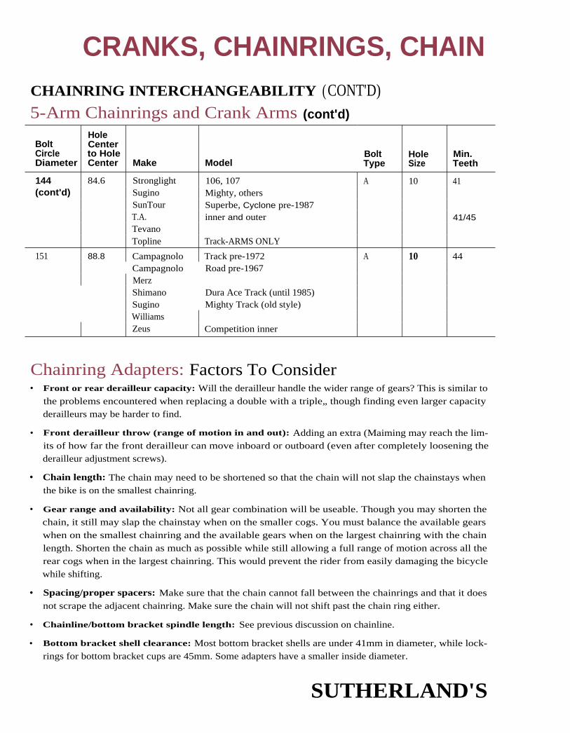
CRANKS, CHAINRINGS, CHAINCHAINRING INTERCHANGEABILITY (CONT'D)5-Arm Chainrings and Crank Arms (cont'd)
BoltCircleDiameter
HoleCenterto HoleCenter Make
BoltModel Type
HoleSize
Min.Teeth
144 84.6 Stronglight 106, 107 A 10 41(cont'd) Sugino Mighty, others
SunTour Superbe, Cyclone pre-1987T.A. inner and outer 41/45TevanoTopline Track-ARMS ONLY
151 88.8 Campagnolo Track pre-1972 A 10 44Campagnolo Road pre-1967MerzShimano Dura Ace Track (until 1985)Sugino Mighty Track (old style)WilliamsZeus Competition inner
Chainring Adapters: Factors To Consider• Front or rear derailleur capacity: Will the derailleur handle the wider range of gears? This is similar to
the problems encountered when replacing a double with a triple„ though finding even larger capacityderailleurs may be harder to find.
• Front derailleur throw (range of motion in and out): Adding an extra (Maiming may reach the lim-its of how far the front derailleur can move inboard or outboard (even after completely loosening thederailleur adjustment screws).
• Chain length: The chain may need to be shortened so that the chain will not slap the chainstays whenthe bike is on the smallest chainring.
• Gear range and availability: Not all gear combination will be useable. Though you may shorten thechain, it still may slap the chainstay when on the smaller cogs. You must balance the available gearswhen on the smallest chainring and the available gears when on the largest chainring with the chain
length. Shorten the chain as much as possible while still allowing a full range of motion across all therear cogs when in the largest chainring. This would prevent the rider from easily damaging the bicycle
while shifting.
• Spacing/proper spacers: Make sure that the chain cannot fall between the chainrings and that it doesnot scrape the adjacent chainring. Make sure the chain will not shift past the chain ring either.
• Chainline/bottom bracket spindle length: See previous discussion on chainline.
• Bottom bracket shell clearance: Most bottom bracket shells are under 41mm in diameter, while lock-rings for bottom bracket cups are 45mm. Some adapters have a smaller inside diameter.
SUTHERLAND'S
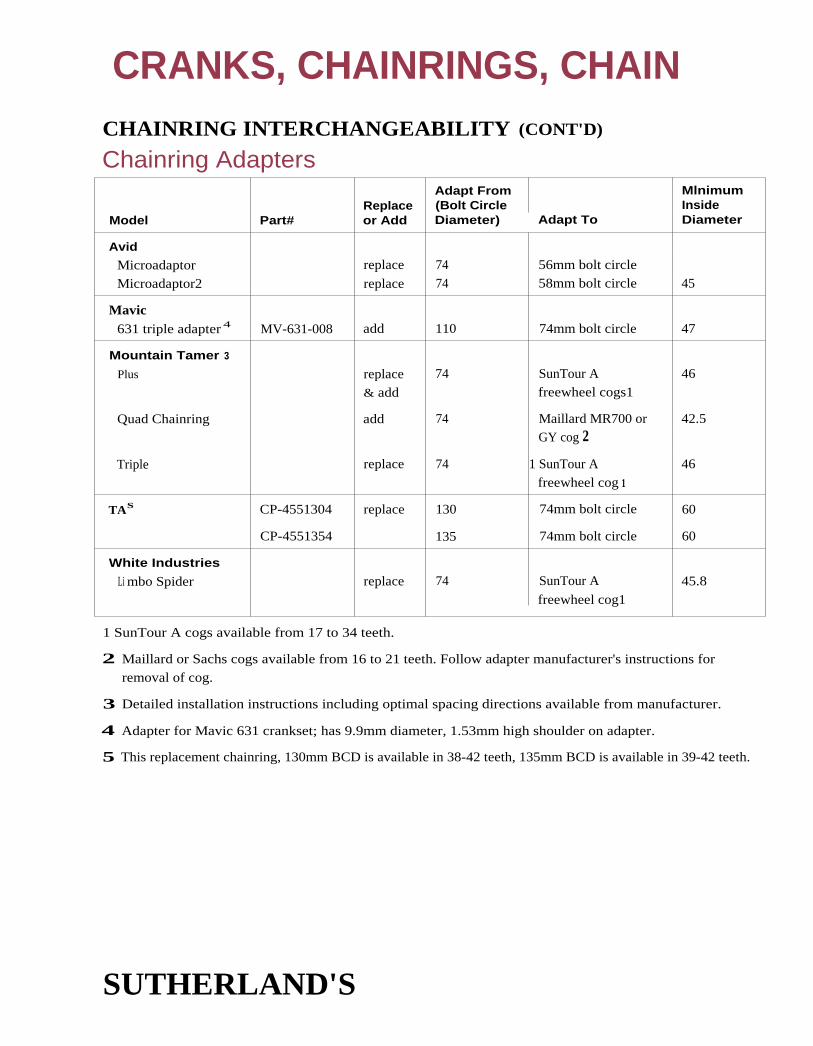
CRANKS, CHAINRINGS, CHAINCHAINRING INTERCHANGEABILITY (CONT'D)
Chainring AdaptersAdapt From Mlnimum
Replace (Bolt Circle InsideModel Part# or Add Diameter) Adapt To Diameter
Avid
Microadaptor replace 74 56mm bolt circle
Microadaptor2 replace 74 58mm bolt circle 45
Mavic631 triple adapter 4 MV-631-008 add 110 74mm bolt circle 47
Mountain Tamer 3
Plus replace& add
74 SunTour Afreewheel cogs1
46
Quad Chainring add 74 Maillard MR700 or 42.5GY cog 2
Triple replace 74 1 SunTour Afreewheel cog 1
46
TAS CP-4551304 replace 130 74mm bolt circle 60
CP-4551354 135 74mm bolt circle 60
White Industries
Li mbo Spider replace 74 SunTour A
freewheel cog1
45.8
1 SunTour A cogs available from 17 to 34 teeth.
2 Maillard or Sachs cogs available from 16 to 21 teeth. Follow adapter manufacturer's instructions forremoval of cog.
3 Detailed installation instructions including optimal spacing directions available from manufacturer.
4 Adapter for Mavic 631 crankset; has 9.9mm diameter, 1.53mm high shoulder on adapter.
5 This replacement chainring, 130mm BCD is available in 38-42 teeth, 135mm BCD is available in 39-42 teeth.
SUTHERLAND'S

CRANKS, CHAINRINGS, CHAINCHAINRING INTERCHANGEABILITY (CONT'D)
5-Pin ChainringsChainrings listed together are interchangeable.
BoltCircleDiameter
HoleCenterto Hole
I Center Make ModelBoltType
HoleSize
Min.Teeth
50.4* 29.6 Many including:CinelliDupratDuraxGnuttiHuretNervarShimanoSimplexSolidaStronglightSugino
TAWilliamsZeus
1004, 1006older Deore
49Pro Dynamic,PX, Super MaxyCriterium, Cyclotouriste
50.8 (2") 29.9 Bullseye
6-Bolt Chainrings
BoltCircleDiameter
HoleCenterto HoleCenter Make Model
BoltType
HoleSize
Min.Teeth
80 40.0 TA 1 CyclotouristeLambert middle bolt
E 7.2 26
116 58.0 TA Randonneur E 7.2 36
143 71.5 Lambert outer bolt circle E 7.2**
152 76.0 TA Criterium E 7.2 43
157 78.5 NervarHaubtmannRFGSolidaSimplexZeus & others
* This is a common bolt circle used with a 40mm hole in the chainring. Bolt sizes are frequently 5 x .75 or5 x .80. Hole sizes in aluminum chainrings are frequently 7 or 8mm or are t hreaded for 5mm bolt insteel chainrings.
** Hole threaded on inner ring.
SUTHERLAND'S

CHAINRING INTERCHANGEABILITY (CONT'D)
3-Arm ChainringsChainrings listed together are interchangeable.
ChainringDimensions
CRANKS, CHAINRINGS, CHAIN
BoltCircleDiameter
HoleCenterto HoleCenter Make Model
BoltType
HoleSize
Min.Teeth
85 73.5 Sakae (SR) Custom 3 A 10 28
88.9(3 1/2")
77 NicklinCrossWilliams
N34N34C34
95 82.3 Shinano 600, 310 A 10 30
106 92 Dague MundoSakae (SR)SuginoTakagi (3 arrows)
CaloiApex w/8mm holesMaxy, othersTourney, American Flyer, others
B 8 32*
106 92 Sakae (SR) Apex w/10mm holes A 10 34
112 97 Takagi (3 arrows) 1 piece crank D 8
116 101 CampagnoloCinelli, DupratDurax, GnuttiHaubtmannMagistroniNervar, SimplexSolidaStronglightTATA Adapter RingZeus and others
Sport, Grand Sport
Professional
C or D 9 36**
140 121.2 Campagnolo Grand Sport. inner B 8 40
Chainrings come in steel and aluminum; there are different spacers for each. Generally, 5mm spacers areused for steel and 3.5mm are used for aluminum.
Often attaches to spigots (raised bumps) on crank arms. This bolt circle is often used with a larger (157mm)bolt circle. Sometimes a piece of metal that looks like this joins the two circles. Nervar, Haubtmann,Solida, Zeus, and most others arc 78.5mm between hole centers. Some Italian chainrings with this large boltcircle use unevenly spaced holes. Pairs of holes were spaced 63.4mm apart on ones we measured.
SUTHERLAND'S

CRANKS, CHAINRINGS, CHAINCHAIN CHARACTERISTICS
Chain Sizes
Nominal Sizein Inches
Nominal Sizein Milllmeters
Chain A X B A X B
Internally Geared Hubsand Coaster Brakes 1/2" X 1/8" 12.7 X 3.17
12.7 X 3.301/2" X 3/16" 12.7 X 4.76
Road/MTB 1/2" X 5/64" 12.7 X 1.981/2" X 3/32" 12.7 X 2.381/2" X 1/8" 12.7 12.7
X 3.17or X 3.3
ATB/MTB 1/2" X 3/32" 12.7 X 3.1712.7 X 3.30
Block Chain (now obsolete) 1 X 3/16" 25.4 X 4.76
Track 1/2" X 1/8" 12.7 12.7X 3.17or X 3.3
* Used for 2, 3 and sometimes 4 and 5 speed freewheels.
Number of LinksYouth — 56
BMX — 96 - 105
Internal Geared — 105-112
ATB, Road — 114 - 118Tandem — 131 - 280
BushingsBushingless chain has the ability to twist more thanchain with bushings. Some systems work best with a
chain that will twist and some with a chain that resiststwist. Be sure to follow the recommendations in eachmanufacturer's section (see Indexing Chapters 5-9).
SUTHERLAND'S

CRANKS, CHAINRINGS, CHAINCHAIN CHARACTERISTICS (CONT'D)
Chain DimensionsThe first number refers to the pitch or the distance between the center of one roller and the
center of the next roller bearing the same load (Dimension A). The second number refers to
the distance between the inside plates or the smallest space for the tooth of the sprocket
(Dimension B). Nominal and actual sizes are not exactly the same.
A narrow chain has the same inside (Dimension B) as a regular 1/2" x 3/32" chain. The outside
(Dimension C) is smaller. A regular width chain is approximately 8.0mm wide while a
narrow chain is 7.2 to 7.4mm wide. This difference allows a 7 or 8 speed freewheel to be used
in the space of a regular 6 speed freewheel. There are a few super narrow chains for use on 8
speeds only, they are approximately 6.8 - 7.2mm wide. The super narrow chains work better
with cogs designed for narrow chains such as Shimano Hyperglide. Regular width chains cannot
be used on narrow 6, 7, and 8 speed freewheels.
Generally a bevelled chain is used with indexing systems. See chain recommendations in
the beginning of each manufacturer's indexing section. Some models can be identified
by the markings on the pin heads.
Chain Width/Pin Length (In Millimeters)
ChainSizein mm
SizeChain in mm
SizeChain in mm
Campagnolo Rohloff ShimanoContax 6.85 SLT 99 Road 6.85 Dura-Ace HG 7.4
Daido (DID)Super L 7.20
SLT 99 MTB 6.95 Dura-Ace UG-HG 7401-UG 30
7.47.47.4
SachsSC-30, 40 7.05
KMC SC-M 50, 55 7.05 Deore XT 11 7.4UG50 7.30 SC-R80 7.05 CN-IG30 7.2HP70 7.30 SC-M90 7.05 CN-IG50 7.2alpha 50HP20
7.307.80
CH-TM10CH-TM20
9.208.10
TayaExtreme 6.85
410 9.40 ReliefTurbo 900Bridge
6.857.307.30
SR/SunTourAPXC ExpertXC-Pro
7.307 .7.277.37
Regina53 Turismo51 Sport50 Corsa
9.309.108.10
Union800 7.40
50 Racing50 SL
7.207.20
810900
7.407.25
50 Anniversario 7.20
SUTHERLAND'S

CRANKS, CHAINRINGS, CHAIN CHAIN CUTTING NOTES
Sedisport ChainSedisport M90, M55, M50, Pro, and ATB chain have mushroomed over pins to help it withstand
side thrust. Special care must be used when removing the chain. These chains have a specialdimpled connecting pin that is located by a single black side plate. Push the pin on the dimpledend when removal is needed. Push the mushroomed non-dimpled end when installing.
Shimano IG, Hyperglide (HG),and Uniglide (UG) ChainIG, Hyperglide (HG), and Uniglide (UG) chains have widened outer plates that require chaintools that are designed for them.
IG and Hyperglide chains have mushroomed over pins that help them withstand side thrust.
When breaking a chain, push a single pin all the way out. When rejoining the chain, use thespecial HG pin to replace the pin you removed. After the new pin is inserted, break off theremaining end with pliers.
The IG chain gauge Shimano tool #130 0600 is used to insure there is enough space between theinner plates after joining a chain. The space required for the teeth of IG sprockets and chainwheels
is 2.38mm. The connecting pins must protrude an equal amount on either side of the chain.
I G and Hyperglide chains are best cut with a straight stroke style chain tool rather than a pliers type.
TayaUse a Sigma Connector to attach the chain. Do not use a chain tool. This chain is 1/2" x 5/64".
It will fit most sprockets and chainrings less than or equal to 2.0mm thick but should only beused on narrow spaced freewheels.
SUTHERLAND'S

CRANKS, CHAINRINGS, CHAINCRANK COTTERS
National ITendenciesand Others Diameter
Overall LengthWithout Nut
Thread .Size
ISO 9.5 (3/8") 43 7mm x 1 mm
English 9.5 (3/8") 43 6.7mm x 26 TPI
French 9.0 40, 43 7mm x 1 mm
German 9.5, common9.0
4343
7mm x 1 mm1/4" x 26 TPI
Italian 9.0, common8.5
4341.5
7mm x 26 TPI7mm x 26 TPI
Japanese 9.5 41.3* 6mm x 1mmJapan Standard1/4" x 26 TPIalso common
Peugeot old style 9.0 37.5 6mm x 1 mm
new style 9.0 42 7mm x 1mm
Steyr 9.5 45 1/4" x 26 TPI
Thompson (adult)(child)
9.58.0
42.543
1/4" x 26 TPI1/4" x 26 TPI
Windsor 8.5 41.5 1 /4" x 26 TPI
Flat
see Appendix
moderate
moderate
moderate
short steep cut
entire length of body cut
moderate
entire length of body cut
moderate cut
moderate cut
short steep cut
* S.R. alloy cottered cranks: use extra long cotters.
8.5mm and 9.0mm holes in cranks may be drilled out to accept 9.5mm cotters.Use a 3/8" drill.
SUTHERLAND'S

CRANKS, CHAINRINGS, CHAIN
SUTHERLAND'S

CONTENTS
3
CupsBall sizes ........................................... 2
Thread sizes
Adjustable and fixed cups ..... 2
Markings .................................. 3
Cup-spindle compatibility ...... 4-5
Fixed cup factors ................... 5
Shell widths ............................. 6
Exceptions ................................ 6
Bottom BracketInterchangeabilityInterchangeability ....................... 7
How to use charts ....................... 7
JIS (Japan Industrial Standard)and clone spindles .......... 8-12
Non-JIS spindle only .......... 1 4-16
Non-PS complete set ......... 15-27
Campagnolo Bottom BracketIdentification ......................... 28
Interchanging parts ........ 28-29
Interchangeability
chart ................................ 29-33
Cartridge Bearingand Cartridge UnitBottom BracketsAbout installing
Straight spindles ........ 34
Shouldered spindles 35
Cartridge units ............ 36
Pressed bearings .............. 37
Design elements .............. 38-54
Cottered Bottom BracketInterchangeabilityEnglish cottered spindle
interchangeability chart ......55
Cottered spindleend diameters ........................ 56
French cottered spindles .......... 56
Other cottered spindles ........... 57
One piece cranks ........................ 58
Thompson (Thun) ....................... 58
SUTHERLAND'S

BOTTOM BRACKETSBOTTOM BRACKET CUPS-BOTTOM BRACKET SHELL
Ball Sizes11 - 1/4" balls per side.Exceptions: Campagnolo used 3/16" balls for one year in the mid-1960's.Campagnolo Super Record and (C-)Record used ball cages with 14 - 3/16" balls.1990 Record uses ball cages with 14 - 7/32" balk.Shimano Selecta uses 15 - 3/16" balls on the left side only.
1S0'English - B.S.CFrench2ItalianRaleigh3SwissChater LeaS
1.375" x 24 TPI. 1.370" x 24 TPI1
35mm x 1mm36mm x 24 TPI1-3/8" x 26 TPI35mm x lmm1.450" x 26 TPI
Adjustable Cup(Left Side)
right-hand threadright-hand threadright-hand threadright-hand threadright-hand threadright-hand threadright-hand thread
Fixed Cup Approx.(Right Side) Shell I.D.
left-hand thread 33.8mmleft-hand thread 33.8mmright-hand thread 33.8mmright-hand thread 34.8mmleft-hand thread 33.8mmleft-hand thread4 33.8mmleft-hand thread
Thread Sizes:Approx.Cup O.D.
34.8mm34.8mm34.8mm35.8mm34.8mm34.8mm
+
ISO size is compatible with English.
1 Raleigh describes Phillips bottom bracket cups as 1-3/8" x 24 TPI Whitworth. This is differentfrom the British Standard Cycle. (See Thread Measuring, page 0-3, for a description ofthread differences.)
2 Motobecane uses left threaded (Swiss style) fixed cups on most hikes. For cottered cranks, it isleft threaded if the fixed cup has 8 flats; it is right threaded if it has 2 flats. (See page 3-3 formarkings on Swiss left-threaded cups for cotterless cranks.)
3 Raleigh U.S.A. uses 1.370 x 24 TPI. With English made bikes such as Raleigh, Rudge, Humber,and brands made by Raleigh after 1963, use 1-3/8" x 26 TPI except for bikes made by Carlton.They use 1.370 x 24 TPI. A Raleigh with 71 or 76mm bottom bracket shell generally uses 26TPI. 67 or 68mm shells use 24 TP1.
4 Some Swiss bikes have French right threaded fixed cups. (See page 3-3 for markings onSwiss left-threaded bottom bracket cups.)
5 This is an obsolete British size which is sometimes found on tandems and other bikes.
Phil Wood & Co. makes mounting rings for their sealed crank bearing that fit all the bottombracket threads listed above, including Chater Lea.
mill All stripped bottom bracket threads except the Italian ones can be reamed out and
re-threaded to Italian. Use a size K expansion reamer or a Bicycle Research bottom
bracket reamer.
Viscount bottom brackets can be reamed and tapped to Italian. Be sure to replace the aluminumforks; they break without warning.
SUTHERLAND'S

FIXED CUP ADJUSTABLE CUP
CAMPAGNOLOEnglish (BSC) 1.370" x 24 TPI 1.370" x 24 TPIFrench 35 x 1 35 x 1Italian 36 x 24F 36 x 24F;Swiss (left-thread) 35 x lG
JAPANESE
& TAIWANESE
English (BSC) 1.370" x 24TPI 1.370" x 24TPI
French 35 x P1 35 x PI
Italian 36 x 24T 36 x 241
Swiss (left-thread) 35 x Pl S1
NERVAR
English (BSC) 1 ring 2 flats 1 ring 6 sides
French no ring no ring 6 sides
Italian 2 rings 2 flats 2 rings 6 sides
RFG
English (BSC) 4CR
French C C
German GL DR
Italian
Raleigh
2 flats
no flange
4 pin hole
STRONGLIGHT*
English (BSC) 2 rings 8 sides 6 sides no rings
French 1 ring 8 sides 6 sides no rings
Italian
,Swiss (left-thread)
1 ring 8 sides
or 1 ring 2 flats
no rings 8 sides
4 pin tool holesno rings
TA
English (BSC) 2 rings 2 rings
French 1 rIng 1 ring
Italian no rings no rings
MARKINGS ON LOCKRING EDGES
4 or 8 notch**6 notch
4 or 8 notch**
BOTTOM BRACKETSBOTTOM BRACKET CUP MARKINGS
* Stronglight Competition for all sizes have 2 flats, no rings.
** Italian lockrings slip over English bottom bracket cups and
English lockrings do not fit over Italian bottom bracket cups.
SUTHERLAND'S

BOTTOM BRACKETSBOTTOM BRACKET CUP-SPINDLE COMPATIBILITYSince bearing race diameters vary, not all conventional bottom brackets using 1/4" balls are compatible.
Spindlediameterat base ofbearingracePeugeot cottered 15.90mm .626 inch
Raleigh cottered 16.40mm .646 inch
Japanese cottered 16.50mm .650 inch
Japanese (JIS) 1 6.50mm .650 inch
Sugino Mighty 1 6.50mm .650 inch
Phillips, other British cottered 1 6.55mm .652 inch
Stronglight, TA 1 6.75mm .659 inch
Campagnolo, SR Royal, 1 6.90mm .665 inch
Shimano Dura-Ace, SunTour
Superbe, Zeus
When possible, use cups and spindles of the same make and model. When mixing brands and
models, test the bearing fit before installing cups in the bicycle. Smear inside of cup lightly with
grease and install bearing balls (balls in retainers are more convenient for this purpose). Insert
spindle and rotate. Remove and note position of ball track on spindle.
Bearing Track
If the bearing track is too high or too low, it will accelerate wear. Especially avoid leaving one
track high and the other low, as this would produce a strong "wedging" force on the races. if one
cup is worn out, find a matching replacement or replace both cups with a matched pair.
Cup race diameters tend to follow spindle race diameters. Individual manufacturing variations
may affect fit. Typically, cups as much as 0.25mm (.010") oversize and 0.12mm (.005") undersize
are acceptable. Due to a more gradual slope of the bearing race surface, Stronglight and Sugino
cups accept a wider range of spindle diameters than others. Sugino Mighty spindles will accept a
wide range of cups, even those made for 16.90mm spindles.
SUTHERLAND'S

BOTTOM BRACKETS
BOTTOM BRACKET CUP-SPINDLE COMPATIBILITY (CONT'D)
Old Combinations That Don't Work• Peugeot cottered spindles and cups will not interchange; its bearing race diameter
is much smaller than the others.
• Old-type Shimano Dura-Ace spindles (BF3-7200, BB-7300, and BB-7500) will not fit throughthe holes in other brands of cups. The entire bottom bracket set is interchangeable.
• Cups for British cottered spindles will not work with many cotterless spindles.
Old Useful Combinations That Do Work• 26 TPI Raleigh cups will work with Maxy-type cotterless spindles.
• Sugino Mighty triple axle will fit in Campagnolo Nuovo Record cups.
• Maxy-type spindles can be used to place chainline farther from the framewith Stronglight or TA cranks.
BOTTOM BRACKET CUP FACTORSWhen exchanging bottom bracket cups, depending on the thickness of the cup, the relative posi-
tion of the spindle may be moved left or right.
To find the amount the bottom bracket spindle has moved, compare the fixed cup factors in the
following table. If the new cup has a greater factor, the spindle will be moved to the left (a small-er factor will move it right). Take care to assure that there will still be enough threads to properly
adjust the lockring when choosing cups with a smaller factor than the old cups.
Make Comments
Fixed Cup Factors- Lockring
ThicknessEnglish French Italian
Campagnolo thin 2.0 2.5 2.5 3.0Campagnolo thick 4.0 4.5 4.0 3.0Nervar 2.5 2.5 3.0Ofmega cadmium-plated - 3.0 2.5-4.0Ofmega chrome-plated - 3.0 4.0Ritchey bulged out 0.0 - 3.5Shimano Dura-Ace* pre '85 1.5 1.5 1.5 3.5Shimano Dura-Ace after '85 4.0 4.0 4.0 3.0Stronglight 2.0 1.5 2.0 4.0SR 3.5 3.5 3.5Sugino Maxy 4.5 4.0 4.5 3.5Sugino Mighty 4.0 4.0 4.0 3.5SunTour 4.0 4.0 4.0 3.0Specialized 4.0 3.5TA 2.5 2.0 3.0 5.0TDC 3.0 - 3.5Zeus - 2.0 --
* Old Dura-Ace cups had larger holes to accommodate a larger diameter axle. Not interchangeablewith others.
SUTHERLAND'S

Bottom bracket shell width
Brand Shell Width i Cottered Spindle Centers Uses
Cinelli(model SCfor severalyears inthe 1960's)
74mm
71 mm (2-13/16") 55.0mm (2-5/32") Most Raleighs,except bikes with24TPI threads
Raleigh
62.0mm (2-7/16") Tourist, Chopper,Twenty, others
76mm (3")
Thompson 65mm, 70mm (See page 3-58.)(Thun)
3-piece stylecranks with press-in cups andthreaded spindles
BOTTOM BRACKETS
BOTTOM BRACKETSHELL WIDTHSThis chart lists only tendencies. As there areexceptions, measure to he sure. Bottom brack-et spindles are made to be used with a specificcup thickness. Different cup thicknesses maycause problems.
Bottom Bracket Shell WidthsStandard Shell Width Cottered Spindle Centers Uses
English 66-67mm oftenlisted as 68mm(2-19/32" – 2-5/8")
52.5mm (2-1/16") Road and track
French 68mm 54.5-56.5mm Road and track
Italian 70mm 56.5-58mm Road
65, 68, 70mm varies Track
Japanese 68, 71 mm 52-53, 55mm Varies
73mm 57 Mountain bike
Exceptions
SUTHERLAND'S

Bolt-typespindle
Nut-typespindle
BOTTOM BRACKETS
BOTTOM BRACKET INTERCHANGEABILITYThe charts on the following pages are for replacing worn spindles, cups, or complete bottom
bracket sets. By comparing the numbers listed, you can determine the differences that affect
the fit of the parts.
Consider this an experimental system which will work when used with care. Please write and
tell us if you have any problems. We are not and cannot be responsible for any difficulties aris-ing from the use of these charts. Occasionally manufacturers change specifications withoutchanging the model names and numbers and measurements also vary from batch to batch
because of manufacturing tolerances. The parts we measured may not be representative, but we
feel the numbers here are close enough to be useful.
Center-width and spindle-end factors are numbers that are useful only when comparing one
spindle to another.
How To Use The Bottom Bracket Charts1. Completely read these steps before starting to disassemble the bottom bracket and cranks.
2. Examine the bicycle. Determine how much the position of the chainrings can be changed. Willthe chainrings rub against the chainstays if they are moved in? Will the derailleur work if the
chainrings are farther out or in? Estimate in millimeters how much the chainrings can go in or
out. Write down your estimate. If you are installing a new crank and bottom bracket, place the
new crank on the old bottom bracket on the bicycle and make your estimates from that position.
3. Note the position of the lockring on the adjustable cup. How many threads are showing?
Write down the number. Estimate how many more or less threads will work. Write that down.
4. Measure the distance from the right-hand edge of the bottom bracket shell to spindle end (donot count threaded section if it is a nut-type spindle). This is the Shell to End, Right
Measurement (SER). Write the measurement down.
5. Remove the crank.
6. Disassemble the bottom bracket set.
7. Measure bottom bracket shell width and spindle length.
8. Determine which parts need replacing. Then, go to the correct chart:
A. Replacing Spindles Only (see also Bottom Bracket Cup-Spindle Compatibility, page3-4). JIS* spindle replacing JIS spindle, (see page 3-8). Non-JIS spindles with balls in retainers,
(see page 3-14).
B. Replacing Complete Set Only, (see page 3-15). JIS bottom bracket sets, (see page 3-8).Non JIS bottom bracket sets with ball retainers, (see page 3-15).
C. Replacing Cups Only. Bottom Bracket Cup Factors, (see page 3-5).
Once you understand how to use the charts, it is possible to use them for other combinations or
replacements. This will, however, increase the possibility that the combinations won't work.
NOTE: For all charts, all dimensions are in millimeters unless otherwise specified.
* JIS spindles are the ones most commonly found in imported bikes.
SUTHERLAND'S

Nut-typespindle
This position indicates the approximateright side (chainring) spindle length:
H is 30.5mmA, L, J are 32mm
P N are 35mmS is 37.5mm
D - 3 N LThis posltion indicates the
approximate left side spindle length.S means shorter than originalL means longer than originalOriginal in this examplewould be a D-3N spindle
BOTTOM BRACKETSOS AND CLONE SPINDLESStamped numbers and letters are consistent enough among makers that dimensions can be listed.Left sides may vary among makers.
Interchangeability(See page 3-7), for further notes on interchangeability, spindle end factors, and SER.
Taper Angle on Spindle Ends(See Taper Angles on page 2-4.)
Crank and Spindle CompatibilityThe square taper of JIS spindles is similar (though longer) to that of older Stronglight and TA
spindles. The square taper of many spindles, including top-of-the-line Japanese, is too narrow
and/or too short to be compatible with cranksets designed for JIS spindles.
Bottom Bracket Cup Compatibilitytype Bearing race diameter is smaller for JIS spindles than for most other spindles except English cot-Bolt -
tered. Do not interchange cups without testing the position of the bearing track (see page 3-4).spindle
Bottom Bracket Shell WidthThe single-digit number stamped on the spindle indicates which shell width to use. 3 is for 68mmbottom bracket shells with 52mm spindle centers. 5 is for 71 mm shells with 55mm spindle centers.
7 is for 73mm shells with 57mm spindle centers. 2 indicates a 65mm shell and 50.5mm center.
Cup thickness varies, so it may be possible to use a spindle with a 55mm center with extra-thin cupsin a 68mm bottom bracket, or a spindle with 52mm center with extra-thick cups in a 71mm bracket.
JIS and Clone Spindle MarkingsNote: there are exceptions and additional letters in the complete spindle chart.
IN THIS POSITION:D indicates bolt-type*No mark indicates nut-typeF indicates SR polished race bolt-type• B after marking also indicates bolt-type;
example: D-3NL = 3NL-B -
IN THIS POSITION:• 2 indicates 65mm bottom bracket
width (50.5mm spindle center)
• 3 indicates 68mm bottom bracket,"width (52.5mm spindle center)
• 5 indicates 70mm bottom bracket width(55mm spindle center — Shimano bolt-typeis listed as 54mm)
• 7 indicates 73mm bottom bracket width(57mm spindle center)
SUTHERLAND'S

)IS AND CLONE SPINDLES
65mm Shell WidthSER denotes shell to end, right measurement.
(See page 3-15 for further explanation.)
CranksetUsed with
Nut-typemarking
Bolt-typemarking
ShimanoCartridgemarking
SuginoBolt-typemarking
Oldmarking
OldShimanomarking A B C
D -SpindleLength
SpindleEndFactor SER
685 32 50.5 32.5 115 9.0 25.25
68K 32 50.5 36 118.5 12.5 28.75
2S 32 50.5 37.5 120 14.0 30.25
2R 32 50.5 42 124.5 18.5 34.75
68mm Shell WidthI
Shimano Sugino Old D - SpindleCrankset Nut-type Bolt-type Cartridge Bolt-type Old Shimano Spindle EndUsed with marking marking marking marking marking marking A B C Length Factor SER
SLP Double SS103 1 03 2.5 18
MM107 1 07 3.5 19
3K D-3K 28 52 28 108 4.5 20
MM 110 110.5 5.5 21
SLP CDTriple 31-B 30 52 29 111 5.5 21
68-S 31 52 30 114 6.5 22
D-3H LL113 3H-B 30.5 52 30.5 113 7.0 22.5
D-H 115 8 23.5
LP Triple 3L,3J D-3L 3j-B 68 W 116 32 52 32 116 8.5 24
XL118 118 9 25
LP Double 3A D-3A 32 52 33.5 117.5 10.0 25.5
3P D-3P 68 W 119 32 52 35 119 11.5 27
Triple 3N D-3N 3N-B 68-W 32 52 36 120 12.5 28
D-3NL D-NL 34.5 52 36 122.5 12.5 28
3N N 3NN-B 36 52 36 124 12.5 28

)IS AND CLONE SPINDLES (CONT'D))
68mm Shell Width (contd)
CranksetUsed with
Nut-typemarking
ShimanoBolt-type Cartridge
I marking marking
SuginoBolt-type marking
Oldmarking
,
OldShimanomarking A B C
D -SpindleLength
SpindleEndFactor SER
Triple 3SS D-3SS 3S-8 68 T 121.5 32 52 37.5 121.5 14.0 29.5
35,(35),3S2 35 52 37.5 124.5 14.0 29.5
3Y D-EL 37.5 52 37.5 127 14.0 29.5
3T D-3T 3T-B 35 52 39 126 15.5 31
3TM-B 37.5 52 39 128.5 15.5 31
D-3TS,
D-3TSP 37.5 52 39 128.5 15.5 31
Triple R3T 39 52 39 130 15.5 31
3TR-B 42 52 39 133 15.5 31
3U D-3U* 3U-B 68-T 32* 52 40.5 124.5* 1 7.0 32.5
3UM 37.5 52 40.5 130 17.0 32.5
3X 40.5 52 40.5 133 17.0 32.5
3R-B 32 52 42 126 18.5 34
3R 35 52 42 129 18.5 r34
3RM 37.5 52 42 131.5 18.5 34
3TR-8 39 52 42 133 18.5 34
3RMC 40.5 52 42 134.5 1 8.5 34
3RR-B 42 52 42 136 18.5 34
3M 35 52 43.5 130.5 20.0 35.5
3IC 135 52 45 132 21.5 37
* Conflicting manufacturer's specifications, use either 32 or 35mm left end width.SER denotes shell to end, right measurement.
(See page 3-1S for further explanation.)

CIS AND CLONE SPINDLES (CONT'D)
70mm Shell Width
CranksetUsed with
Nut-typemarking
Bolt-typemarking
ShimanoCartridgemarking
SuginoBolt-typemarking
Oldmarking
OldShimanomarking A B C
D -SpindleLength
SpindleEndFactor SER
SLP Double SS103 103 .5 16.5
SLP Dbl/Trp MM107 1 07 3.0 18.5
D-5K 27 54 27 108 3.5 19
SLP Triple MM1 10 110.5 4.5 20.5
LL113 113 6.0 21.5
D-H 115 7.0 22.5
5H D-5H 30.5 55 30.5 116 7.0 22.5
XL118 118 8.0 24
5L 5IB 30.5 55 32 117.5 8.5 24.5
5LL D-5L*,D-5LL 70 W 119 32* 55 32 119 8.5 24.5
5A D-5A 31 54 32.5 117.5 9.0 24.5
5P D-5P 30.5 55 33.5 119 1 0.0 2670-W 32 55 34 121 10.5 26.5
Single 5N 5N-B 70 W 122 32 55 35 122 11.5 27.5
D-5NL D-NL 33.5 54 35 122.5 11.5 27
Double 5SB 32 55 36 1 23 12.5 28.5
D-EL 127.5 13.5 29.5
5SP D-5SP** 30.5** 55 37.5 123** 14.0 30
5SS D-5S 5S-B 70 T 124.5 32 55 37.5 124.5 14.0 30
5S, (55) 35 55 37.5 127.5 14.0 30
70-T' 32 55 38.5 125.5 15.0 31
Double 5T D-5T 5T-B 35 55 39 129 15.5 31.5
D-5U* 5U-B 32 55 40.5 127.5 17.0 33
Triple 5U 35 55 40.5 130.5 17.0 33
SR 35 55 42 132 18.5 34.5
* Conflicting manufacturer's specifications, use either 32 or 35mm left end width.
** Conflicting manufacturer's specifications, either 30.5 or 35mm left end width.SER denotes shell to end, right measurement.
(See page 3-15 for further explanation.)

OS AND CLONE SPINDLES (CONT'D)
73mm Shell Width
CranksetUsed with
Nut-typemarking
Bolt-typemarking
ShimanoCartridgemarking
SuginoBolt-typemarking
Oldmarking
OldShimanomarking A B C
D -SpindleLength
SpindleEndFactor SER
MM107 107 1.5 1 7
MM110 110.5 3.0 19
LL113 113 4.5 20
D-H 115 5.5 20
D-7H XL118 30.5 57 30.5 118 7.0 22.5
Triple 7NL D-7NL D-NL 32 57 33.5 122.5 10.0 25.5
D-EL 127.5 12.5 28
7EL D-7EL 35 57 36 128 13.0 28D-7TL 35 57 39 131 15.5 31
SER denotes shell to end, right measurement.
(See page 3-15 for further explanation.)

BOTTOM BRACKETS
SUTHERLAND'S

BOTTOM BRACKETSI NSTRUCTIONS FOR REPLACING SPINDLE ONLYThe most effective way to replace just a spindle in a loosebottom brackets is to match the A, B, and C dimensions inthe chart. The bearings must contact the proper area onthe races, (see page 3-4). Match the number and size ofthe balls for the old and new spindles. For example: A
spindle designed for 1/4" ball bearings probably will
work with a spindle designed for 7/32" balls.
A spindle with different A, B, or C dimensions will give the following variations. An increase in
C will move the chainrings out if they are too close to the chainstays. An increase in A will bringthe left crankarm out. An increase in B will move the left crankarm and the adjustable cup out. Asmaller B is possible only if there are sufficient threads showing on the adjustable cup. On rare
occasions, the chainrings can be moved out by inserting a freewheel spacer between the fixedcup and the frame, and using larger B dimension.
To get the best results, try to match the taper you already have. A good match will help preventany spindle-to-crankarm incompatibilities like bottoming the fixing bolt against the spindle orthe crankarm bottoming against the spindle shoulder. (See page 3-5 for combinations thatdon't work.) It will also keep your chainline calculations relatively consistent. Mixing tapersmay introduce errors of up to 5mm in the chainline calculations. For instance: if you were to
replace a French taper (it is important not to get taper and threading mixed up) with a
Japanese spindle with the same dimensions, the crankarms would be between 3mm -
5mmfarther away from the frame on each side.
The spindle end and center width factors, which are included from previous editions of this
book, may be useful when mixing tapers on older spindles. The factors have the same effect as Band C and can be used instead of B and C as long as you use them exclusively. Match the center
width factor and spindle end factor for both of your old and replacement bottom brackets.
Non-JIS Bottom Bracket Spindle Interchangeability
ModelUsed with
ModelNumber
SpindleMarking
ShellWidth A B C
0 -SpindleLength
ClosestTaperEnd Size
Avocet
Double (USA) 114.0 20 68 30.0 54.0 30.0 114.0 CampyTriple (USA) 119.5 30 68 30.5 55.0 34.0 119.0 CampyDouble 120.0 2 68 31.5 57.0 31.5 120.0 Ofmega*Triple 125.5 3 68 32.5 57.0 36.0 126.0 Ofmega*
* Otmega taper ends are smaller than others and are not interchangeable.
SUTHERLAND'S

BOTTOM BRACKETSI NSTRUCTIONS FOR REPLACING COMPLETE SETPreserving a chainline is important when replacing a bottom
bracket set. To preserve the chainline, the distance between
the bottom bracket shell and the end of the spindle needs
to be the same for the original bottom bracket set and
the replacement set. This distance is called the SER, Shell
to End Right measurement.
It is also important to match the shell width the bottom
bracket sets are designed for and check the position of the leftcrank arm.
SER denotes shell to end, right measurement.
The above rough method for choosing the proper bottom bracket will work with most modem
spindles. Errors of 1.5mm are within manufacturers' tolerances. Expect up to 2mm variance due
to differences in torque, grease on the bolt, grease on the spindle taper (not recommended),grease on washers, or serrations on the nut or bolt. if you avoid mixing Italian or French bottom
bracket sets with JIS sets, then your errors should be less than 3mm.
When mixing older bottom bracket sets, for example, a French bottom bracket set with newer
Japanese standard bottom bracket sets, the taper end size differences may add up to errors of
5mm or more. (See page 3-5 for older combinations that don't work.) In previous edi-
tions, we attempted to minimize these errors by using our spindle end and center width factor.
By comparing these factors, you could estimate the changes in chainlines and the number ofthreads available for a lockring. We have included these charts in this edition also. SFR is easier
to use than the spindle end and center width factors because it is a more direct measurement
and can be determined for any bottom bracket using inexpensive calipers (or even a decent rule
and a good eye).
Non-JIS Complete Bottom Bracket Set Interchangeability
SPINDLE ONLYCOMPLETE BOTTOM BRACKET SET ONLY
ENGLISH FRENCH ITALIANSER L/R center I spindle center spindle I center splndle center !spindle(right Taper width end width end width end width endoverhang) Length factor factor factor factor factor factor factor factor
Avocet
23 15/15.5 74.5 6.0 67.5 6.0 68.0 5.5 68.0 5.5
27.5 15/15.5 75.5 10.0 68.0 10.0 69.0 9.5 68.5 9.5
26 15/15 77.5 7.5 68.0 6.5 68.0 6.5 70.0 5.5
30.5 15/15 77.5 12.0 68.0 11.0 68.0 11.0 70.0 10.0
SUTHERLAND'S
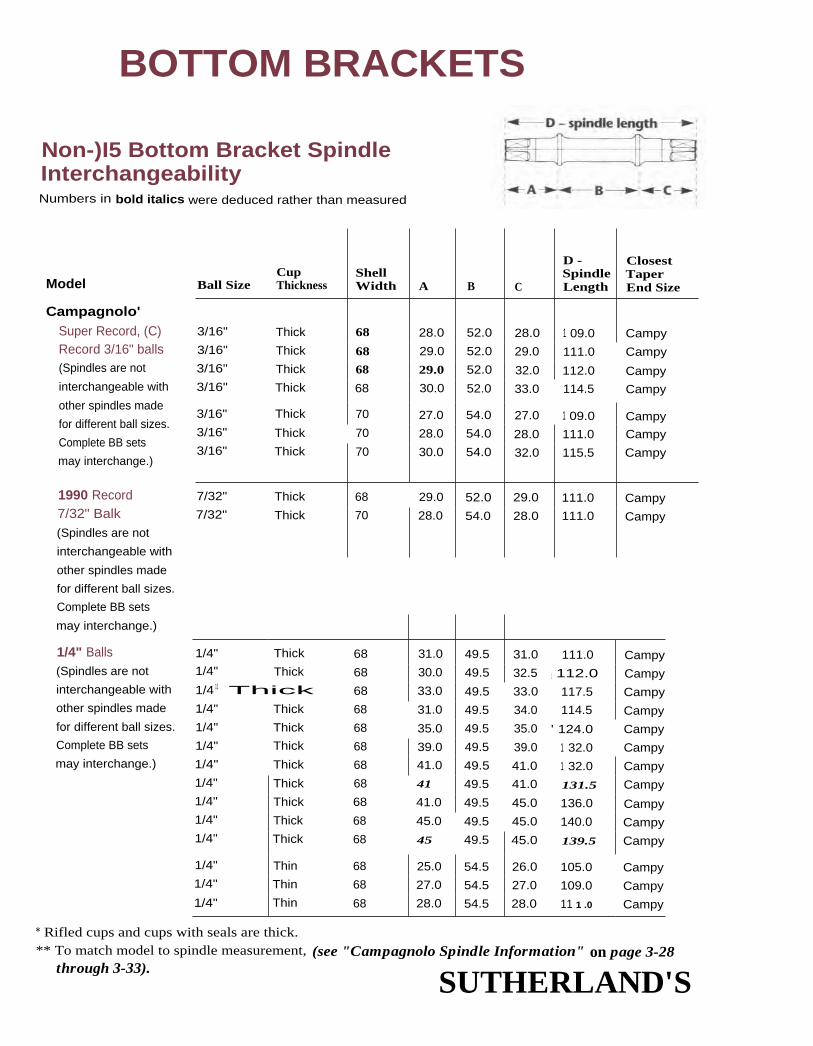
BOTTOM BRACKETS
Non-)I5 Bottom Bracket SpindleInterchangeabilityNumbers in bold italics were deduced rather than measured
Model
Campagnolo'Super Record, (C)Record 3/16" balls(Spindles are not
interchangeable with
other spindles made
for different ball sizes.
Complete BB sets
may interchange.)
1/4" Balls(Spindles are not
interchangeable with
other spindles made
for different ball sizes.
Complete BB sets
may interchange.)
1990 Record7/32" Balk(Spindles are not
interchangeable with
other spindles made
for different ball sizes.
Complete BB sets
may interchange.)
CupBall Size Thickness
ShellWidth A B C
D -SpindleLength
ClosestTaperEnd Size
3/16" Thick 68 28.0 52.0 28.0 1 09.0 Campy3/16" Thick 68 29.0 52.0 29.0 111.0 Campy3/16" Thick 68 29.0 52.0 32.0 112.0 Campy3/16" Thick 68 30.0 52.0 33.0 114.5 Campy
3/16" Thick 70 27.0 54.0 27.0 1 09.0 Campy3/16" Thick 70 28.0 54.0 28.0 111.0 Campy3/16" Thick 70 30.0 54.0 32.0 115.5 Campy
7/32" Thick 68 29.0 52.0 29.0 111.0 Campy7/32" Thick 70 28.0 54.0 28.0 111.0 Campy
1/4" Thick 68 31.0 49.5 31.0 111.0 Campy1/4" Thick 68 30.0 49.5 32.5 1 112.0 Campy1/4 11 Thick 68 33.0 49.5 33.0 117.5 Campy1/4" Thick 68 31.0 49.5 34.0 114.5 Campy1/4" Thick 68 35.0 49.5 35.0 ' 124.0 Campy1/4" Thick 68 39.0 49.5 39.0 1 32.0 Campy1/4" Thick 68 41.0 49.5 41.0 1 32.0 Campy1/4" Thick 68 41 49.5 41.0 131.5 Campy1/4" Thick 68 41.0 49.5 45.0 136.0 Campy1/4" Thick 68 45.0 49.5 45.0 140.0 Campy1/4" Thick 68 45 49.5 45.0 139.5 Campy
1/4" Thin 68 25.0 54.5 26.0 105.0 Campy1/4" Thin 68 27.0 54.5 27.0 109.0 Campy1/4" Thin 68 28.0 54.5 28.0 11 1 .0 Campy
* Rifled cups and cups with seals are thick.** To match model to spindle measurement, (see "Campagnolo Spindle Information" on page 3-28
through 3-33).SUTHERLAND'S

BOTTOM BRACKETS
Non-JIS Complete BottomBracket Set Interchangeability
SER denotesshell to end, right
measurement.See page 3-15
for furtherexplanation.
COMPLETE BOTTOM BRACKET SET ONLYSPINDLE ONLY ENGLISH FRENCH ITALIAN
SER L/R(right Taperoverhang) Length
centerwidthfactor
spindleend
factor
centerwidthfactor
spindleend
factor
centerwidthfactor
spindleend
factor
center spindlewidth endfactor factor
Campagnolo
20 15/15 70.0 5.5 67.0 3.5 68.0 3.0 68.5 3.5
21 15/15 70.0 6.5 67.0 4.5 68.0 4.0 68.5 4.5
24 1 5/15 70.0 9.5 67.0 7.5 68.0 7.0 68.5 7.5
25 1 5/15 70.0 1 0.5 67.0 8.5 68.0 8.0 68.5 8.5
1 9 15/15 72.0 7.0 69.0 5.0 70.0 4.5 69.5 4.5
20 15/15 72.0 8.0 69.0 6.0 70.0 5.5 69.5 5.5
24 15/15 72.0 1 2.0 69.0 1 0.0 70.0 9.5 69.5 9.5
21 15/15 67.0 4.5 68.0 4.0 68.5 4.5
20 1 5/15 69.0 6.0 70.0 5.5 69.5 5.5
22 15/15 70.0 6.5 67.0 4.5 68.0 4.0 68.5 4.5
23.5 15/15 70.0 8.5 67.0 6.5 68.0 6.0 68.5 6.5
24 15/15 70.0 8.5 67.0 6.5 68.0 6.0 68.5 6.5
25 15/15 70.0 9.0 67.0 8.0 68.0 7.5 68.5 8.0
26 15/15 70.0 1 0.0 67.0 9.0 68.0 8.5 68.5 9.0
30 1 5/15 70.0 1 4.0 67.0 13.0 68.0 1 2.5 68.5 1 3.0
32 15/15 70.0 16.0 67.0 15.0 68.0 1 4.5 68.5 15.0
32 15/15 70.0 1 6.0 67.0 1 5.0 68.0 1 4.5 68.5 15.0
36 15/15 70.0 20.0 67.0 19.0 68.0 1 8.5 68.5 19.0
36 1 5/15 70.0 20.0 67.0 1 9.0 68.0 1 8.5 68.5 19.0
36 15/15 70.0 20.0 67.0 1 9.0 68.0 1 8.5 68.5 1 9.0
1 9.5 15/15 75.0 1.5 68.0 1.5 69.0 1.0 68.5 1.0
20.5 15/15 75.0 3.0 68.0 3.0 69.0 2.5 68.5 2.5
21.5 1 5/15 75.0 4.0 68.0 4.0 69.0 3.5 68.5 3.5
SUTHERLAND'S
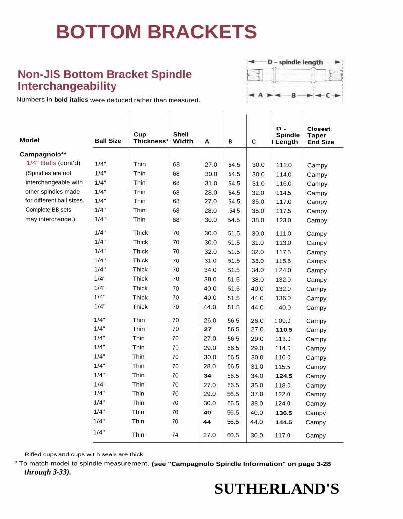
BOTTOM BRACKETS
Non-JIS Bottom Bracket SpindleInterchangeabilityNumbers in bold italics were deduced rather than measured.
Ball SizeCupThickness*
ShellWidth A B C
D -Spindle
I Length
ClosestTaperEnd Size
1/4" Thin 68 27.0 54.5 30.0 112.0 Campy1/4" Thin 68 30.0 54.5 30.0 114.0 Campy1/4" Thin 68 31.0 54.5 31.0 116.0 Campy1/4" Thin 68 28.0 54.5 32.0 114.5 Campy1/4" Thin 68 27.0 54.5 35.0 117.0 Campy1/4" Thin 68 28.0 .54.5 35.0 117.5 Campy1/4" Thin 68 30.0 54.5 38.0 123.0 Campy
1/4" Thick 70 30.0 51.5 30.0 111.0 Campy1/4" Thick 70 30.0 51.5 31.0 113.0 Campy1/4" Thick 70 32.0 51.5 32.0 117.5 Campy1/4" Thick 70 31.0 51.5 33.0 115.5 Campy1/4" Thick 70 34.0 51.5 34.0 1 24.0 Campy1/4" Thick 70 38.0 51.5 38.0 132.0 Campy1/4" Thick 70 40.0 51.5 40.0 132.0 Campy1/4" Thick 70 40.0 51.5 44.0 136.0 Campy1/4" Thick 70 44.0 51.5 44.0 1 40.0 Campy
1/4" Thin 70 26.0 56.5 26.0 1 09.0 Campy1/4" Thin 70 27 56.5 27.0 110.5 Campy1/4" Thin 70 27.0 56.5 29.0 113.0 Campy1/4" Thin 70 29.0 56.5 29.0 114.0 Campy1/4" Thin 70 30.0 ' 56.5 30.0 116.0 Campy1/4" Thin 70 28.0 56.5 31.0 115.5 Campy1/4" Thin 70 34 56.5 34.0 124.5 Campy1/4' Thin 70 27.0 56.5 35.0 118.0 Campy1/4" Thin 70 29.0 56.5 37.0 122.0 Campy1/4" Thin 70 30.0 56.5 38.0 124.0 Campy1/4" Thin 70 40 56.5 40.0 136.5 Campy1/4" Thin 70 44 56.5 44.0 144.5 Campy
1/4" Thin 74 27.0 60.5 30.0 117.0 Campy
Model
Campagnolo**1/4" Balls (cont'd)
(Spindles are not
interchangeable with
other spindles made
for different ball sizes.
Complete BB sets
may interchange.)
Rifled cups and cups wit h seals are thick.
" To match model to spindle measurement, (see "Campagnolo Spindle Information" on page 3-28through 3-33).
SUTHERLAND'S

SER denotesshell to end, right
measurement.See page 3-15
for furtherexplanation.
BOTTOM BRACKETS
Non-JIS Complete BottomBracket Set Interchangeability
COMPLETE BOTTOM BRACKET SET ONLY
SER L/R(right Taperoverhang) Length
SPINDLE ONLY ENGLISH FRENCH ITALIAN
centerwidthfactor
spindleend
factor
centerwidthfactor
spindleend
factor
centerwidthfactor
spindleend
factor
center widthfactor
spindleend
factor
Campagnolo
23.5 15/15 75.0 6.0 68.0 6.0 69.0 5.5 68.5 5.5
23.5 15/15 75.0 6.0 68.0 6.0 69.0 5.5 68.5 5.5
24.5 15/15 75.0 6.5 68.0 6.5 69.0 6.0 68.5 6.0
25.5 15/15 75.0 7.5 68.0 7.5 69.0 7.0 68.5 7.0
28.5 1 5/15 75.0 1 0.0 68.0 1 0.0 69.0 9.5 68.5 9.5
28.5 15/15 75.0 1 0.0 68.0 1 0.0 69.0 9.5 68.5 9.5
31.5 1 5/15 75.0 13.5 68.0 1 3.5 69.0 13.0 68.5 13.0
21 15/15 72.0 7.0 69.0 5.0 70.0 4.5 69.5 4.5
22 15/15 72.0 8.0 69.0 6.0 70.0 5.5 69.5 5.5
23 15/15 72.0 9.0 69.0 7.0 70.0 6.5 69.5 6.5
24 15/15 72.0 9.5 69.0 7.5 70.0 7.0 69.5 7.0
25 15/15 72.0 1 0.0 69.0 8.0 70.0 7.5 69.5 7.5
29 15/15 72.0 1 4.0 69.0 12.0 70.0 11.5 69.5 11.5
31 15/15 72.0 1 6.0 69.0 14.0 70.0 13.5 69.5 1 3.5
35 15/15 72.0 20.0 69.0 1 8.0 70.0 1 7.5 69.5 1 7.5
35 15/15 72.0 20.0 69.0 1 8.0 70.0 1 7.5 69.5 1 7.5
1 9.5 15/15 77.0 2.0 70.0 2.0 70.5 1.5 70.5 1.5
20.5 15/15 77.0 3.0 70.0 3.0 70.5 2.5 70.5 2.5
22.5 15/15 77.0 5.0 70.0 5.0 70.5 4.5 70.5 4.5
22.5 15/15 77.0 5.0 70.0 5.0 70.5 4.5 70.5 4.5
23.5 15/15 77.0 6.0 70.0 6.0 70.5 5.5 70.5 5.5
24.5 15/15 77.0 6.5 70.0 6.5 70.5 6.0 70.5 6.0
27.5 15/15 77.0 1 0.0 70.0 1 0.0 70.5 9.5 70.5 9.5
28.5 15/15 77.0 11.0 70.0 11.0 70.5 1 3.5 70.5 1 3.5
30.5 15/15 77.0 13.0 70.0 1 2.0 70.5 1 2.5 70.5 12.5
31.5 15/15 77.0 1 4.0 70.0 1 4.0 70.5 1 3.5 70.5 13.5
33.5 1 5/15 77.0 1 6.0 70.0 16.5 70.5 1 5.5 70.5 15.5
37.5 15/15 77.0 20.0 70.0 20.5 70.5 1 9.5 70.5 1 9.5
23.5 15/15 81.0 i 3.0 , 74.0 3.0 74.5 3.0 74.0 3.0
SUTHERLAND'S
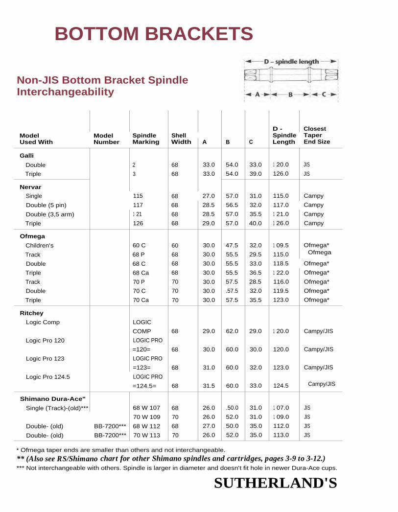
BOTTOM BRACKETS
Non-JIS Bottom Bracket SpindleInterchangeability
D - ClosestModel Model Spindle Shell Spindle TaperUsed With Number Marking Width A B C Length End Size
Galli
Double 2 68 33.0 54.0 33.0 1 20.0 JIS
Triple 3 68 33.0 54.0 39.0 126.0 JIS
Nervar
Single 115 68 27.0 57.0 31.0 115.0 Campy
Double (5 pin) 117 68 28.5 56.5 32.0 117.0 Campy
Double (3,5 arm) 1 21 68 28.5 57.0 35.5 1 21.0 Campy
Triple 126 68 29.0 57.0 40.0 1 26.0 Campy
Ofmega
Children's 60 C 60 30.0 47.5 32.0 1 09.5 Ofmega*
Track 68 P 68 30.0 55.5 29.5 115.0 Ofmega
Double 68 C 68 30.0 55.5 33.0 118.5 Ofmega*
Triple 68 Ca 68 30.0 55.5 36.5 1 22.0 Ofmega*
Track 70 P 70 30.0 57.5 28.5 116.0 Ofmega*
Double 70 C 70 30.0 .57.5 32.0 119.5 Ofmega*
Triple 70 Ca 70 30.0 57.5 35.5 123.0 Ofmega*
Ritchey
Logic Comp LOGIC
COMP 68 29.0 62.0 29.0 1 20.0 Campy/JIS
Logic Pro 120 LOGIC PRO
=120= 68 30.0 60.0 30.0 120.0 Campy/JIS
Logic Pro 123 LOGIC PRO
=123= 68 31.0 60.0 32.0 123.0 Campy/JIS
Logic Pro 124.5 LOGIC PRO
=124.5= 68 31.5 60.0 33.0 124.5 Campy/JIS
Shimano Dura-Ace"
Single (Track)-(old)*** 68 W 107 68 26.0 .50.0 31.0 1 07.0 JIS
70 W 109 70 26.0 52.0 31.0 1 09.0 JIS
Double- (old) BB-7200*** 68 W 112 68 27.0 50.0 35.0 112.0 JIS
Double- (old) BB-7200*** 70 W 113 70 26.0 52.0 35.0 113.0 JIS
* Ofmega taper ends are smaller than others and not interchangeable.
** (Also see RS/Shimano chart for other Shimano spindles and cartridges, pages 3-9 to 3-12.)*** Not interchangeable with others. Spindle is larger in diameter and doesn't fit hole in newer Dura-Ace cups.
SUTHERLAND'S

SER denotesshell to end, right
measurement.See page 3-15
for furtherexplanation.
BOTTOM BRACKETS
Non-JIS Complete BottomBracket Set Interchangeability
COMPLETE BOTTOM BRACKET SET ONLY
SER L/R(right Taperoverhang) Length
SPINDLE ONLY L ENGLISH FRENCH ITALIANcenterwidthfactor
spindleend
factor
centerwidthfactor
spindleend
factor
center I spindlewidth endfactor factor
centerwidthfactor
spindleend
factor
Galli26 15/15 74.0 11.0 68.0 9.5 68.0 9.5 70.0 9.532 15/15 74.0 17.0 68.0 15.5 68.0 15.5 70.0 15.5
Nervar25.5 16/16 76.0 7.5 69.5 7.5 69.5 7.026.5 16/16 75.5 8.5 69.0 8.0 69.0 8.030 16/16 76.0 12.0 69.0 12.0 69.0 12.034.5 16/16 76.0 16.5 69.0 16.5 69.0 16.5
Ofmega26 15/15.5 67.5 7.5 60.0 6.5 60.0 5.5 60.0 4.523.5 15/15.5 78.5 5.0 68.0 4.0 68.0 4.0 68.0 3.027 15/15.5 75.5 8.5 68.0 7.5 68.0 6.5 68.0 5.5
30.5 15/15.5 75.5 13.0 68.0 12.0 68.0 11.0 68.0 10.0
22.5 15/15.5 77.5 4.0 70.0 3.0 70.0 3.0 70.0 2.026 15/15.5 77.5 7.5 70.0 6.5 70.0 5.5 70.0 4.529.5 15/15.5 77.5 12.0 70.0 11.0 70.0 1 0.0 70.0 9.0
Ritchey
26 15.5/15 81.0 5.5 68.0 9.5
26 15.5/15 79.0 6.5 68.0 9.5
28 15.5/15 79.0 8.5 68.0 11.5
29 15.5/15 79.0 9.5 68.0 12.5
Shimano Dura -Ace21.5 15/15 68.0 2.0 68.0 2.0 68.5 2.0 68.5 1.5
21 15/15 70.0 1.5 70.0 1.5 70.5 1.5 70.0 1.0
26 15/15 68.0 6.5 68.0 6.5 68.5 6.5 68.5 6.0
25.5 15/15 70.0 6.0 70.0 6.0 70.5 6.0 70.0 5.5
SUTHERLAND'S

BOTTOM BRACKETS
Non-PS Bottom Bracket SpindleInterchangeability
ModelUsed With
ModelNumber
SpindleMarking
ShellWidth A B C
D -SpindleLength
ClosestTaperEnd Size
Shimano Dura-Ace**
(cont'd)
Double- (old) BB-7300 68 S 107 68 26.0 50.0 31.0 107.0 JIS(7500 AX)"*
Double- (old) BB-7300 70 S 109 70 26.0 52.0 31.0 109.0 JIS(7500 AX)***
Single (Track) BB-7600 68 S 68 27.0 50.0 32.0 1 09.0 CampySingle (Track) BB-7600 70-S 70 25_5 52.0 31.5 1 09.0 CampyDouble BB-7400 68 W 112 68 27.0 50.0 35.0 112.0 CampyDouble BB-7400 70 W 1 13 70 26.5 52.0 34.5 113.0 CampyDouble BB-7400 68-W 68 27.0 50.0 35.0 112.0 CampyDouble BB-7400 70-W 70 26.5 52.0 34.5 113.0 Campy
Salida
Single (Track) 118.5 68 29.0 58.0 31.5 118.5Double 122 68 28.5 58.0 35.5 122.0Triple 125 68 28.0 58.0 39.0 1 25.0Mountain, BMX 129 68 34.0 58.0 37.0 1 29.0
Specialized
Double 107-68 68 28.5 50.0 28.5 1 07.0 CampyDouble 109-70 70 28.5 52.0 28.5 1 09.0 CampyCampagnolo
Double (pre '85) 112-68 68 29.5 50.0 32.5 112.0 CampyCampagnolo
Double (pre '85) 113-70 70 29.5 52.0 31.5 113.0 CampyTriple 114.5-68 68 30.5 50.0 34.0 114.5 CampyTriple 115.5-70 70 30.5 52.0 33.0 115.5 CampyCampagnolo,
TA triple (pre '85) 119.5-68 68 30.5 50M 39.0 119.5 CampySpecialized Mtn.triple 120-68 68 35.0 50.0 35.0 1 20.0 CampyCampagnolo,
TA triple (pre '85) 120.5-70 70 30.5 52.0 38.0 , 120.5 Campy
** (Also see JIS/Shimano chart for other Shimano spindles and cartridges, pages 3-9 to 3-12.)
*** Not interchangeable with others. Spindle is larger in diameter and doesn't fit hole in newer Dura-Ace cups.
SUTHERLAND'S

BOTTOM BRACKETS
Non-JIS Complete BottomBracket Set Interchangeability
SER denotesshell to end, right
measurement.See page 3-15
for furtherexplanation.
COMPLETE BOTTOM BRACKET SET ONLYSPINDLE ONLY ENGLISH FRENCH ITALIAN
SER L/R(right Taperoverhang) Length
centerwidthfactor
spindleend
factor
centerwidthfactor
spindleend
factor
center ' spindle I centerwidth end widthfactor factor factor
spindleend
factor
Shimano Dura-Ace
(cont'd)
21.5 15/15 68.0 2.0 68.0 2.0 68.5 2.0 68.5 1.5
21 1 5/15 70.0 1.5 70.0 1.5 70.5 1.51
70.0 1.0
23 15/15 69.0 8.5 68.0 3.5 68.5 3.5 68.5 3.0
22.5 15/15 71.0 8.0 70.0 3.0 70.5 3.0 70.0 3.5
26 15/15 69.0 11.5 68.0 6.5 68.5 6.5 68.5 6.0
25.5 1 5/15 71.0 11.0 70.0 6.0 70.5 6.0 70.0 5.5
26 15/15 69.0 11.5 68.0 6.5 68.5 6.5 68.5 6.0
25.5 15/15 71.0 11.0 70.0 6.0 70.5 6.0 70.0 5.5
Solida
26.5 77.0 8.0 68.5 8.0 68.5 8.5 70.0 8.0
30.5 77.0 1 2.0 68.5 1 2.5 68.5 1 2.5 70.0 1 2.0
34 77.0 1 5.5 68.5 1 5.5 68.5 1 6.0 70.0 1 5.5
32 77.0 1 3.5 68.5 13.5 68.5 1 4.0 70.0 13.5
Specialized
1 9.5 1 4.5/14.5 70.5 4.0 67.5 2.0 67.5 2.0 67.5 2.0
1 9.5 1 4.5/14.5 72.5 4.0 69.5 2.0 69.5 2.0 69.5 2.0
23.5 14.5/14.5 70.5 8.0 67.5 6.0 67.5 6.0 67.5 6.0
22.5 14.5/14.5 72.5 7.0 69.5 5.0 69.5 5.0 69.5 5.0
25 1 4.5/14.5 70.5 9.5 67.5 7.5 67.5 7.5 67.5 7.5
24 1 4.5/14.5 72.5 8.5 69.5 6.5 69.5 6.5 69.5 6.5
30 14.5/14.5 70.5 14.5 67.5 1 2.5 67.5 12.5 67.5 12.5
26 14.5/14.5 70.5 1 0.5 67.5 8.5 67.5 8.5 67.5 8.5
29 1 4.5/14.5 72.5 1 3.5 69.5 11.5 69.5 11.5 69.5 11.5
SUTHERLAND'S

BOTTOM BRACKETS
Non-JIS Bottom Bracket SpindleInterchangeability
ModelUsed With
ModelNumber
SpindleMarking
ShellWidth A B C
D -SpindleLength
ClosestTaperEnd Size
Specialized (cont'd)
Specialized Mtn.triple 125-68 68 37.5 50.0 37.5 125.0 Campy
Specialized Mtn.triple 1 27-68 68 38.5 50.0 38.5 127.0 Campy
Sugino Mtn. triple 130-68 68 10.5 50.0 40.5 130.0 Camp
SR Royal
Single T-68-S 68 27.5 51.0 27.5 1 06.0 JIS
Double R-68 68 29.0 51.0 32.0 112.0 JIS
Double R-70 70 31.0 53.0 31.0 115.0 JIS
Triple R-68-T 68 32.0 51.0 35.5 118.5 JI5
Stronglight
Single (Track) 113 68 28.5 56.0 28.5 113.0 JIS
Double
(w/5 pin cranks) 118 68 30.5 56.0 32.0 118.5 JIS
Double
(w/5 arm cranks) 120 68 30.5 56.0 33.5 120.0 JIS
Double (w/5 arm
cranks) (Peugeot) 1 21 68 30.5 56.0 35.0 121.5 JIS
Double
(w/5 arm cranks) 123 68 30.5 56.0 37.0 123.5 JIS
Triple 125 68 30.5 56.0 38.5 1 25.0 JIS
Triple (Peugeot) 126 68 30.5 56.0 39.5 126.0 JIS
Tandems 130 68 30.5 56.0 43.5 130.0 JIS
Tandem Triple 133 68 30.5 56.0 46.5 133.0 JIS
Mountain Bike 134.5 68 39.0 56.0 39.5 134.5 JIS
Sugino 75, MightySingle (Track) MS-68 or
MW-68LP 68 29.0 51.5 29.0 109.0 Campy
Double (Road) MW-68 orMT-68LP 68 29.0 51.5 35.0 114.0 Campy
Double (Road) MW-70 70 29.0 53.5 32.5 115.0 Campy
Triple MT-68 68 29.5 51.5 38.0 120.0 Campy
Triple MT-70 70 29.5 53.5 37.0 120.0 Campy
SUTHERLAND'S

SER denotesshell to end, right
measurement.See page 3-15
for furtherexplanation.
BOTTOM BRACKETS
Non-JIS Complete BottomBracket Set Interchangeability
COMPLETE BOTTOM BRACKET SET ONLY
SER L/R(right Taperoverhang) Length
SPINDLE ONLY ENGLISH FRENCH ITALIANcenterwidthfactor
spindleend
factor
center spindlewidth endfactor factor
center spindlewidth endfactor factor
centerwidthfactor
spindleend
factor
Specialized
28.5 1 4.5/14.5 70.5 13.0 67.5 11.0 67.5 11.0 67.5 11.0
29.5 14.5/14.5 70.5 14.0 67.5 1 2.0 67.5 12.0 67.5 12.0
31.5 1 4.5/14.5 70.5 1 6.0 67.5 14.0 67.5 14.0 67.5 14.0
SR Royal
19 16/16 71.0 5.0 66.5 2.5 66.5 3.5
23.5 16/16 71.0 9.5 66.5 7.5 66.5 8.0
22.5 16/16 73.0 7.5 68.5 5.5 68.6 6.0 69.5 5.5
27 16/16 71.0 1 6.0 66.5 14.0 66.5 14.5
Stronglight
22.5 14/16 77.0 5.0 70.0 5.0 69.5 5.0 71.0 5.0
26 1 4/16 77.0 8.0 69.0 8.0 68.5 8.5 70.0 8.0
27.5 1 4/16 77.0 1 0.0 68.0 10.0 67.5 1 0.5 69.0 10.0
29 1 4/16 77.0 11.0 68.5 11.0 68.5 11.5 70.0 11.0
31 1 4/16 77.0 13.0 68.5 13.5 68.5 13.5 70.0 13.0
32.5 1 4/16 77.0 1 5.5 68.5 15.5 68.5 1 6.0 70.0 1 5.5
33.5 1 4/16 77.0 16.5 68.5 1 6.5 68.5 1 7.0 70.0 1 6.5
37.5 14/16 77.0 20.0 68.5 20.0 68.5 20.5 70.0 20.0
40.5 1 4/16 77.0 23.0 68.5 23.0 68.5 23.5 70.0 23.0
33.5 1 4/16 77.0 15.5 68.5 15.5 68.5 16.0 70.5 15.5
Sugino 75, Mighty
21 71.0 4.0 67.5 1.5 68.0 2.0 67.5 1.5
27 71.0 9.5 67.5 7.0 68.0 7.5 67.5 7.0
24.5 73.0 7.5 69.5 5.5 70.0 5.5 69.5 5.5
30 71.0 13.5 67.5 11.0 68.0 11.5 69.5 11.0
29 71.0 11.5 69.5 9.5 70.0 9.5 69.5 9.5
SUTHERLAND'S

BOTTOM BRACKETS
Non-JIS Bottom Bracket SpindleInterchangeability
ModelUsed Wlth
ModelNumber
SpindleMarking
ShellWidth A B C
D -SpindleLength
ClosestTaperEnd Size
SunTourSuperbe, Sprint BB-SB10,
BB-5000 68-S 68 29.5 50.0 29.5 1 09.0 CampySuperbe, Sprint BB-S810,
BB-5000 70-5 70 28.5 52.0 28.5 1 09.0 CampyCyclone-(Vx)-Taper BB-400 68-W 68 31.5 50.0 31.5 113.0 JIS
Cyclone-(Vx)-Taper BB-400 70-W 70 31.5 52.0 31.5 115.0 JIS
XC-Pro BB-XP00 68-35 68 36 52 37.5 125.5 JIS
TA, Trevano
Single (Track) 314 68 28.0 55.5 28.0 111.5 JIS
Double 344 68 30.0 55.5 31.0 116.5 JIS
Double 373 68 30.0 55.5 34.5 120.0 JIS
Triple 374 68 30.0 55.5 38.0 1 23.5 JIS
ZeusSingle (Track) 1 09 x 55P 68 27.0 55.0 27.0 109.0 ISO
Chronos, New Racer 1 09 x 57P 70 26.0 57.0 26.0 109.0 ISO
Double (Road) 114 x 55C 68 29.5 55.0 29.5 114.0 ISO
Double (Road) 114 x 57C 70 28.5 57.0 28.5 114.0 ISO
Double (Road) 118 x 55C 68 29.5 55.0 33.5 118.0 ISO
Double (Road) 118 x 57C 70 28.5 57.0 32.5 118.0 ISO
Triple 123 x 55T 68 29.5 55.0 , 38.5 123.0 ISO
Triple 123 x 57T 70 28.5 57.0 37.5 1 23.0 ISO
SUTHERLAND'S

BOTTOM BRACKETS
Non-JIS Complete BottomBracket Set Interchangeability
SER denotesshell to end, right
measurement.See page 3-15
for furtherexplanation.
SER L/R(right Taperoverhang) Length
SPINDLE ONLYCOMPLETE BOTTOM BRACKET SET ONLY
ENGLISH FRENCH ITALIANcenterwidthfactor
spindleend
factor
centerwidthfactor
spindleend
factor
centerwidthfactor
spindleend
factor
center 1 spindlewidth endfactor factor
SunTour
20.5 1 4.5/14.5 70.0 5.5 67.0 3.5 68.0 3.0 68.5 6.5
1 9.5 1 4.5/14.5 72.0 4.5 69.0 2.5 70.0 2.0 69.5 3.5
22.5 1 6/16 70.0 8.0 67.0 6.0 68.0 5.5 68.5 8.0
22.5 1 6/16 72.0 9.5 69.0 7.5 70.0 7.0 69.5 7.0
29 17/17
TA, Trevano22 1 6.5/16.5 76.0 6.5 69.5 6.0 69.0 6.5 71.0 5.0
25 1 6.5/16.5 76.0 9.5 69.0 9.0 68.5 9.5 70.5 8.0
28.5 1 6.5/16.5 75.0 14.0 68.5 1 3.0 68.0 13.5 70.0 12.5
32 1 6.5/16.5 75.5 16.0 69.0 15.0 68.5 15.5 70.5 14.5
Zeus
20.5 14.5/15 75.0 0.5 68.0 0.5 68.5 0.0 68.0 0.5
1 9.5 14.5/15 77.0 -0.5 70.0 -0.5 70.5 -1.0 70.0 -0.5
23 1 4.5/15 75.0 5.0 68.0 5.0 68.5 4.5 68.0 5.0
22 1 4.5/15 77.0 4.0 70.0 4.0 70.5 3.5 70.0 4.0
27 1 4.5/15 75.0 9.0 68.0 9.0 68.5 8.5 68.0 9.0
26 1 4.5/15 77.0 8.0 70.0 8.0 70.5 7.5 70.0 8.0
32 14.5/15 75.0 1 4.0 68.0 14.0 68.5 I 13.5 68.0 14.0
31 14.5/15 77.0 13.0 70.0 13.0 70.5 12.5 70.0 13.0
SUTHERLAND'S

Number in thisposition indicatesbottom bracketshell widthin mm.
X3 indicates that thespindle was intendedfor triple chainwheels.
Letters in this positionindicate intended use:SS - roadP - trackSP - road or track
Road spindles (marked SS) with a 3-digitnumber here are pre-1978. The 3-digitnumber was used to indicate ideal rearhub width, 120 in this example. Thisnumber lasted longer for track spindles.
BOTTOM BRACKETSCAMPAGNOLO BOTTOM BRACKET IDENTIFICATION
MARKINGS
When identifying Campagnolo bottom brackets, it is best to use all the available evidence. Start withthe marking on the spindle; there are many different spindles with the same marking. Next, identifythe ball sizes it is used with. Most spindles use 1/4 " balls. Spindles with a 1mm step between thebearing surface and the main shaft use 3/16" or 7/32" balls. Measure the spindle center to determineif it normally is used with thick cups or thinner cups (see columm B in charts on pages 29-31).Then, if needed, measure the right side, the left side, and the overall length to confirm you have anexact match. In the following tables under cups, rifled refers to the spiral grooves in the hole.
I NTERCHANGING CAMPAGNOLOBOTTOM BRACKET PARTSBall sizes cannot be interchanged. Each spindle is designed for a specific ball size and cup sizeand cannot be mixed.
Interchanging Complete Bottom Bracket SetsGenerally, complete bottom bracket sets with the same overall length of spindle and marked
with the same shell width can be interchanged without moving the chainline.
Examples: The following complete bottom bracket sets are interchangeable as a unit:
68-SS Chorus length 111mm68-SS Croce d'Aune length 111mm68-SS ( C-) Record length 111 mm
Interchanging Bottom Bracket Spindles OnlyGenerally bottom bracket spindles that use the same ball size, have the same length and the cen-
ter size can be interchanged without moving the chain line.
Example: The following bottom bracket spindles are interchangeable:
68-P-120 (old) Record Track length 109mm
68-SS Victory length 109mm
SUTHERLAND'S

BOTTOM BRACKETSMoving the ChainlineSubstituting a 68-SS Chorus spindle at 111 mm for a 68-SS Victory spindle at 109mm will move the
chainline out 1mm. Study the charts carefully and note that the similarities of the dimensions willshow many substitutions when moving the chainline is possible or needed.
Interchanging CupsSuper Record cups interchange with (C.- Record (pre-1990 with 3/16" bearings) cups. Croced'Aune cups interchange with Nuovo Record Cups. Chorus cups interchange with Athena,Triomphe Record, and Gran Sport cups. Thick, sealed cups for mountain bikes are the same
thickness for spacing purposes as thick, rifled-hole cups.
CAMPAGNOLO BOTTOM BRACKET SPINDLEINTERCHANGEABILITYPre-1978 Bottom Brackets: 11 the marking +1.0 — +1.5 appears in addition to the other mark-
ings, (see 1978 Spindles om page 3-30).
Campagnolo Super Record Spindles with 3/16" Balls
No.-size MarkingBalls/cage on spindle A B C
1
D CupsChain-rings Models
' 14 - 3/16" 65 - P - 110 25 54.0 25 1 04 thin* Track Super Record
14-3/16" 68 - P - 1 10 24 57.0 25 1 05 thin* Track Super Record
1 4 - 3/16" 68 - P - 120 26 57.0 26 109 thin* Track Super Record
14-3/16" 68-55-120 29 52.0 32 112 thick, rifled* Double Super Record
I 14-3/16" 70 - P - 120 25 59.0 25 1 09 thin* Track Super Record
[ 1 4-3/16" 70-SS-120 29 54.0 30 113 thick, rifled* Double Super Record
* Aluminum with steel insert
Campagnolo Spindles with 1/4" Balls
No.-sizeBalls/cage
Markingon spindle A B C D Cups
Chain-rings Models
11-1/4" 65-P-110 26 51.5 ' 26 104 thin Track (old) Record
11-1/4" 68-P-110 25 54.5 26 1 05 thin Track (old) Record
11-1/4" 68-P-120 27 54.5 27 109 thin Track (old) Record
11-1/4" 68-SS-120 29 49.5 33 112 thick, rifled* Double Nuovo Record
11 - 1/4" 68-SS-120 27 54.5 30 112 thin Double (old) Record, Gran Sport
11-1/4" 68-SS-120 X3L
27-
54.5 35 117 thin Triple (old) Record, Gran Sport
Aluminum with steel insert
SUTHERLAND'S
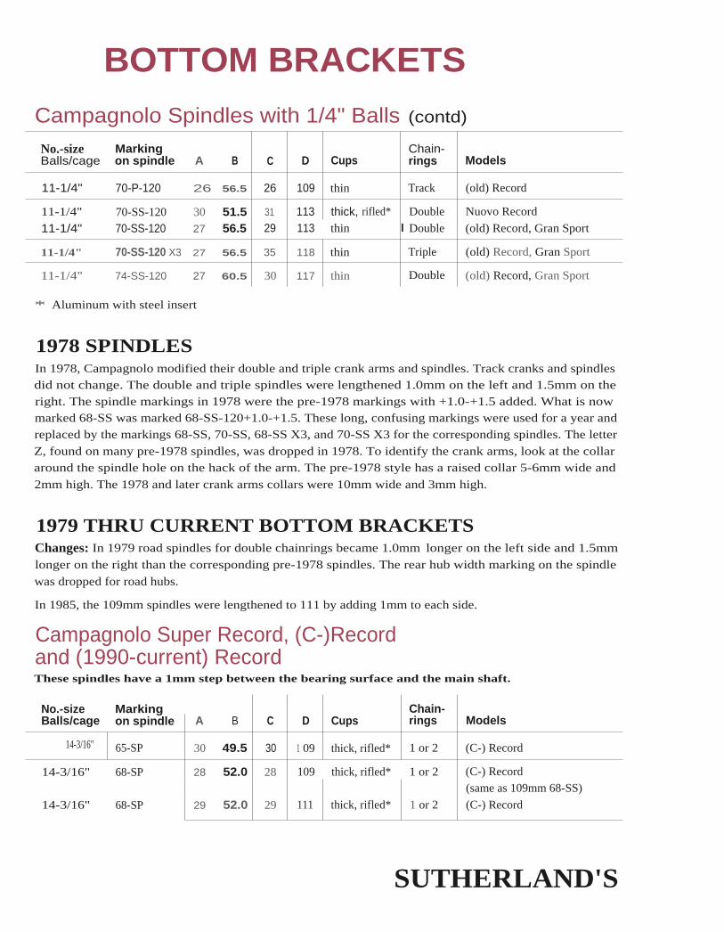
BOTTOM BRACKETSCampagnolo Spindles with 1/4" Balls (contd)
No.-size MarkingBalls/cage on spindle A B C D Cups
Chain-rings Models
11-1/4" 70-P-120 26 56.5 26 109 thin Track (old) Record
11-1/4" 70-SS-120 30 51.5 31 113 thick, rifled* Double Nuovo Record
11-1/4" 70-SS-120 27 56.5 29 113 thin I Double (old) Record, Gran Sport
11-1/4" 70-SS-120 X3 27 56.5 35 118 thin Triple (old) Record, Gran Sport
11-1/4" 74-SS-120 27 60.5 30 117 thin Double (old) Record, Gran Sport
* Aluminum with steel insert
1978 SPINDLESIn 1978, Campagnolo modified their double and triple crank arms and spindles. Track cranks and spindlesdid not change. The double and triple spindles were lengthened 1.0mm on the left and 1.5mm on theright. The spindle markings in 1978 were the pre-1978 markings with +1.0-+1.5 added. What is nowmarked 68-SS was marked 68-SS-120+1.0-+1.5. These long, confusing markings were used for a year andreplaced by the markings 68-SS, 70-SS, 68-SS X3, and 70-SS X3 for the corresponding spindles. The letter
Z, found on many pre-1978 spindles, was dropped in 1978. To identify the crank arms, look at the collar
around the spindle hole on the hack of the arm. The pre-1978 style has a raised collar 5-6mm wide and
2mm high. The 1978 and later crank arms collars were 10mm wide and 3mm high.
1979 THRU CURRENT BOTTOM BRACKETSChanges: In 1979 road spindles for double chainrings became 1.0mm longer on the left side and 1.5mm
longer on the right than the corresponding pre-1978 spindles. The rear hub width marking on the spindle
was dropped for road hubs.
In 1985, the 109mm spindles were lengthened to 111 by adding 1mm to each side.
Campagnolo Super Record, (C-)Recordand (1990-current) RecordThese spindles have a 1mm step between the bearing surface and the main shaft.
No.-size Marking Chain-Balls/cage on spindle A B C D Cups rings Models
14-3/16" 65-SP 30 49.5 30 1 09 thick, rifled* 1 or 2 (C-) Record
14-3/16" 68-SP 28 52.0 28 109 thick, rifled* 1 or 2 (C-) Record
(same as 109mm 68-SS)
14-3/16" 68-SP 29 52.0 29 111 thick, rifled* 1 or 2 (C-) Record
SUTHERLAND'S

BOTTOM BRACKETS1979 THRU CURRENT BOTTOM BRACKETS (CONT'D)
Campagnolo Super Record, (C-)Recordand (1990-current) Record (cont'd)These spindles have a 1mm step between the bearing surface and the main spindle shaft.
No.-size Marking Chain-Balls/cage on spindle A B C D Cups rings Models
14-3/16" 68-SS 28 52.0 28 109 thick, rifled* 1 or 2 (C-) Record
(same as 109mm 68-SP)
14-3/16" 68-SS 30 52.0 33 114.5 thick, rifled* Double Super Record Road
14-3/16" 70-SP 27 54.0 27 109 thick, rifled* 1 or 2 (C-) Record
(same as 109mm 70-SS)
14-3/16" 70-SP 28 54.0 28 111 thick, rifled* 1 or 2 (C-) Record
14-3/16" 70-SS 27 54.0 27 109 thick, rifled* 1 or 2 (C-) Record
(same as 109mm 70-SP)
14-3/16" 70-SS 30 54.0 32 115.5 thick, rifled* Double Super Record Road
14-7/32" 68-SP C 29 52.0 29 111 thick, rifled* 1 or 2 (1990-current) Record
14-7/32" 70-SP C 28 54.0 28 111 thick rifled 1 or 2 (1990-current) Record
* Aluminum with steel insert
SUTHERLAND'S

BOTTOM BRACKETS
1979 THRU CURRENT BOTTOM BRACKETS (CONT'D)
Campagnolo Spindles with 1/4" BallsParenthesis around the marking sometimes indicates using the spindle with thick cups such as the
Croce d' Aune. These spindles have narrower centers than those used with thin cups.
No.-sizeBalls/cage
Markingon spindle A B C D Cups
Chain-wheels Models
11-1/4" 68-SS 27 54.5 27 109 thin Double Victory11-1/4" 68-SS 27 54.5 30 112 thin 2 or 3 Triomphe double, Victory triple11-1/4" 68-SS or 31 49.5 31 111 thick, rifled** Double Croce d'Aune
68-SS A11-1/4" 68-SPc 30.5 50.0 30.5 111 thick, rifled** Double Record/Record OR11-1/4" 68-SS or 28 54.5 28 111 thin Double Chorus
68-SS B11-1/4" 68-SS or 30 54.5 30 114 thin Double Athena - black
68-SS G*11-1/4" 68-SS G* 31 54.5 31 116 thin Double Athena - black (current)11-1/4" 68-SS F 31 54.5 31 116 thin Double Xenon - black11-1/4" 68-SS Fl 33 49.5 33 117.5 thick** Double Xenon - black11-1/4" 68-SS 31 49.5 34 114.5 thick, rifled** Double Nuovo Record11-1/4" 68-SS 28 54.5 32 114.5 thin Double (old) Record, Gran Sport
11-1/4" 68-SS X3 28 54.5 35 117.5 thin Triple (old) Record-grey
11-1/4" 68-SS X3 30 54.5 38 123 thin Triple Gran Sport-black
11-1/4" 68-S5 X3-M 41 49.5 41 132 with seal** Triple Euclid 132 (w/center bulge)
11-1/4" 68-SS X3-M 41 49.5 45 136 with seal** Triple Euclid 136 (w/center bulge)
11-1/4" 68-SS X3- 45 49.5 45 140 with seal** Triple Euclid 1 40 (w/center bulge)
M SPE
11-1/4" 68-SS X3-S 35 49.5 35 124 with seal** Triple Centaur 1 24 - black
11-1/4" 68-SS X3- 39 49.5 39 132 with seal** Triple Centaur 132 - black
S SPE
11-1/4" 68-SS X3§ 35 49.5 35 124 with seal** Triple Olympus 124 - black
11-1/4" 68-SS X3§ 39 49.5 39 132 with seal** Triple Olympus 132 - black
SPE
11-1/4" 70-SS 26 56.5 26 1 09 thin Double Victory
11-1/4" 70-SS 27 56.5 29 113 thin 2 or 3 Triomphe double, Victory triple
11-1/4" 70-SS or 30 51.5 30 111 thick, rifled** Double Croce d'Aune
70-SS A
11-1/4" 70-SPc 29.5 52.0 29.5 111 thick, rifled** Double Record/Record OR
11-1/4" 70-SS or 27 56.5 27 111 thin Double Chorus
70-SS B
' 68-SS G was first produced as 114mm, then as 1 16mm.
** For spacing purposes, thick, rifled-hole cups, cups with a seal, and thick Xenon cups are the same thickness.
SUTHERLAND'S

BOTTOM BRACKETS
1979 THRU CURRENT BOTTOM BRACKETS (CONT'D)Campagnolo Spindles with 1/4" Balls (cont'd)Parenthesis around the marking sometimes indicates using the spindle with thick cups such as the
Croce d' Aune. These spindles have narrower centers than those used with thin cups.
No.-size Marking Chain-Balls/cage on spindle A B C D Cups wheels Models
11-1/4" 70-SS or 29 56.5 29 114 thin Double Athena - black
70-SS G
11-1/4" 70-SS F 30 56.5 30 116 thin Double Xenon - black
11-1/4" 70-SS Fl 32 51.5 32 117.5 thick** Double Xenon - black
11-1/4" 70-SS 31 51.5 33 115.5 thick, rifled** Double Nuovo Record
11-1/4" 70-SS 28 56.5 31 115.5 thin Double (old) Record, Gran Sport
11-1/4" 70-SS X3 29 56.5 37 122 thin Triple (old) Record-grey
11-1/4" 70-SS X3 30 56.5 38 124 thin Triple Gran Sport-black
11-1/4" 70-SS X3-M 40 51.5 40 132 with seal** Triple Euclid 132 (w/center bulge)
11-1/4" 70-55 X3-M 40 51.5 44 136 with seal** Triple Euclid 136 (w/center bulge)
11-1/4" 70-SS X3- 44 51.5 44 140 with seal** Triple Euclid 140 (w/center bulge)
M SPE
11-1/4" 70-SS X3-S 34 51.5 34 124 with seal** Triple Centaur 124 - black
11-1/4" 70-SS X3- 38 51.5 38 132 with seal** Triple Centaur 132 - black
S SPE
11-1/4" 70-SS X3§ 34 51.5 34 124 with seal** Triple Olympus 124 - black
11-1/4" 70-SS X3§ 38 51.5 38 132 with seal** Triple Olympus 132 - black
SPE
** For spacing purposes, thick, rifled-hole cups, cups with a seal and thick Xenon cups are the same thickness.
SUTHERLAND'S

cup
bearing
locking collar
Complete Straight SpindleBottom Bracket Set
Straight Spindle Only
BOTTOM BRACKETS
CARTRIDGE BEARING BOTTOM BRACKETSThere are three main types of cartridge bearing bottom brackets: straight spindles; fixed, shoul-dered spindles; and cartridge units.
Preserving the chainline is important when replacing a bottom bracket set. To preserve the
chainline, the distance between the bottom bracket shell and the end of the spindle
needs to be the same for the original bottom bracket set and the replacement set. This
distance is called the SER, Shell to End Right measurement.
Straight SpindleThe spindle of a straight spindle bottom bracket has no shoulder, lip, or flange. Locking collars
that slide along the spindle until tightened determine the position of the spindle end. This
makes for an easily adjustable chainline. Straight spindles can be installed in various widths ofbottom bracket shells.
Replacing just the cartridge bearings is possible. Straight spindles that press fit into the bearings
may require special tools or may he installed much like a shouldered spindle.
Installing Straight SpindlesChoosing a spindle is relatively easy since a straight spindle allows for almost infinite adjust-
ment. Fit the crank arm to the spindle properly. The spindle must be long enough so neither
crank arm hits the frame under load: start by matching t he new spindle length to the old.
Install a straight spindle bottom bracket by threading the cups into the bottom bracket shell;tighten them in place. Then, insert the spindle, adjust the position of the spindle, slip the locking
collars over the spindle, butt them against the bearings, and tighten the locking collars in place.The new SER should match the old SER plus or minus any desired adjustments to the chainline.
Super Low Profile cranks: locking collars may be too thick for a proper chainline using super
low profile cranks. One option is to use the locking collars inboard of the bearings, although this
may be time consuming to set up properly and may expose the bearing seals to t he elements.
SUTHERLAND'S

BOTTOM BRACKETSCARTRIDGE BEARING BOTTOM BRACKETS (CONT'D)
Fixed or Shouldered SpindlesWith a fixed spindle bottom bracket, the spindle has shoulders that butt up against the hearings.The cartridge bearings may be either pressed onto the spindle or into the cups. Replacing just the
cartridge bearings is possible.
Do not confuse the dust sleeve of a fixed shouldered bottom bracket with the shell of a cartridge
unit bottom bracket. The two types of spindles are adjusted differently. A bottom bracket withno lockrings or flanges, or with one flange and no lockring on the other side, is usually a car-
tridge unit.
Shouldered Spindle Only Complete ShoulderedBottom Bracket Set
Installing Shouldered Spindles (with one or two adjustable cups)Choose replacements carefully as the SER is slightly adjustable only if both cups are adjustable.The new SER should match the old SER plus or minus ally desired adjustments to the chain line.
Installing shouldered spindles with one or two adjustable cups is similar to a regular loose bear-ing bottom bracket. Install the right side cup, and insert the spindle (and hearings, if they are
separate). Then install the other cup and adjust it until there is no side-to-side play in the bear-ings. If there are two adjustable cups, the chainline line may be adjusted slightly if there are
enough threads for the lockrings. The final adjustment must not have any side load on the bear-ings. Side load pushes the balls in the cartridge to the side of the bearing surface instead of the
middle where the load belongs. Check for drag by turning the spindle.
Installing Shouldered Spindles (with two fixed cups)Choose replacements carefully as the new SIR must match the old SLR plus or minus any desired
adjustments to the chainline.
Installing shouldered spindles with two fixed cups may require spacers for either the spindle, orthe cups, or both. install the first cup and the spindle. While tightening the second cup, check
the side-to-side play of the spindle. If there is no play and the fixed cup is still not fully tight-
ened, remove a spacer from the spindle or add a freewheel spacer to either fixed cup. Thenattempt to tighten it down again. Add shims (supplied by the manufacturer) to the spindle
between the spindle and bearings or between the the bearings and the cups until there is little
side play in the spindle when both cups are tightened. The amount of play should be about thesame as or less than the smallest shim thickness. If there is no side play, there might be too
much side load on the bearings. Check for drag by turning the spindle.
SUTHERLAND'S
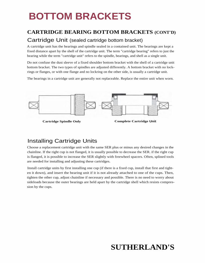
BOTTOM BRACKETSCARTRIDGE BEARING BOTTOM BRACKETS (CONT'D)
Cartridge Unit (sealed cartridge bottom bracket)A cartridge unit has the hearings and spindle sealed in a contained unit. The bearings are kept a
fixed distance apart by the shell of the cartridge unit. The term "cartridge bearing" refers to just thebearing while the term "cartridge unit" refers to the spindle, bearings, and shell as a single unit.
Do not confuse the dust sleeve of a fixed shoulder bottom bracket with the shell of a cartridge unit
bottom bracket. The two types of spindles are adjusted differently. A bottom bracket with no lock-rings or flanges, or with one flange and no lockring on the other side, is usually a cartridge unit.
The bearings in a cartridge unit are generally not replaceable. Replace the entire unit when worn.
Cartridge Spindle Only Complete Cartridge Unit
Installing Cartridge UnitsChoose a replacement cartridge unit with the same SER plus or minus any desired changes in thechainline. If the right cup is not flanged, it is usually possible to decrease the SER. if the right cup
is flanged, it is possible to increase the SER slightly with freewheel spacers. Often, splined toolsare needed for installing and adjusting these cartridges.
Install cartridge units by first installing one cup (if there is a fixed cup, install that first and tight-
en it down), and insert the bearing unit if it is not already attached to one of the cups. Then,tighten the other cup, adjust chainline if necessary and possible. There is no need to worry aboutsideloads because the outer bearings are held apart by the cartridge shell which resists compres-
sion by the cups.
SUTHERLAND'S

BOTTOM BRACKETS
CARTRIDGE BEARING BOTTOM BRACKETS (CONT'D)
Pressed In Bearings or Unthreaded Bottom Bracket ShellsBikes such as the Klein, early Merlin, or certain Fishers have unthreaded bottom bracket shells
and require the spindle and bearings to be pressed into the shell instead of using threaded cups.Usually they use a straight spindle and are held into place by an interference fit and Loctite(sleeve retainer, not thread locker). Manufacturers, like Fisher, also offer a combination of shoul-
dered spindles, a press fit, and retaining clips to keep everything in place.
Eor the straight spindle, special tools are needed to press the bearings onto the spindle and intothe bottom bracket shell. Install the bearings and spindle carefully, and in the proper order so asnot to ruin the bearings. Do not place too great of an unsupported side load on them.
Various manufacturers make press fit straight spindles to fit the bearings used in these hikes. Slipfit spindles can be used in place of press fit spindles if there is enough room to fit the locking col-
lars for the spindles. Even proper shouldered spindles may be used in their place, if installed with
an unusual amount of care.
The positioning of shouldered spindles is preset, but avoid sideloads on the bearings. This istnie especially if there is an interference fit between the spindle and bearing and between the
bearing and shelL
Instructions are provided with the tools for installation and removal of the bearings and spindle.
Because cartridge bearings are narrower than standard cups, they can place a more concentratedload on the bottom bracket shell. Press fit bearings are usually at the edge of the bottom bracket
shell and have no other support; if the shell is not thick enough, the bearings may deform theshell. When the shell is deformed, the crank can develop up and down play that might be mis-taken for a worn bearing. If the whole bearing and spindle moves up and down together, the
shell is deformed and a bearing cannot be press fit in. In this case, it would be best to contact theframe manufacturer for warranty.
Depending on the size of the bottom bracket shell, it may also be possible to use one of the car-tridge units mentioned on the previous page. The important thing is to get the cartridge unit to
rest on the bottom of the shell and to distribute any downward force all across the shell insteadof at the edges of the shell. Check for further damage to the bottom bracket shell before
installing the bottom bracket.
Other Bottom BracketsSome manufacturers make cartridge unit bottom brackets that do not need a threaded shell or apress fit. Most common is the Mavic bottom bracket (others include the Edco, FAG, and the
YST). These bottom brackets are held in by holding both sides of the shell in opposition, much
li ke a C clamp. They keep their concentric alignment by having close tolerances or having a con-ical/wedge shape that fits them in and centers them. The Mavic uses a conical shape to wedge
itself in and a bottom bracket shell chamfered to the same conical shape for better contact.
SUTHERLAND'S

BOTTOM BRACKETS
DESIGN ELEMENTSAction TecThe Attack Bracket System has shouldered spin-dles made for 68mm bottom bracket shells andhas no chainline adjustability (both cups are like
fixed cups). Adjust the bearings by using shims
that fit between the spindle and bearings until
there is less than 1.5mm of play.
SER denotes shell to end, right measurement.
See page 3-15 for further explanation.
For 73mm bottom bracket shells, two 2.5mm spacers slip on the spindle to effectively move the
shoulders out. This decreases the SER and the Spindle End Factor by 2.5. Then the shims are used
again to reduce play.
The Attack Bracket Spindle uses the same cups but has slip fit straight spindles and locking col-
lars (6.6mm thick).
Slight recesses in cups may accommodate some super low profile cranks, but do not providemuch clearance. 1.4mm protrudes from the bottom bracket shell edge, which sticks out 5.2mmwith the locking collars. The 6903 (or 61903) bearings are pressed into cups from inside.Although this is counter intuitive for external collars, they are pretty securely pressed in.
Attack Bracket System spindles are available in: 107, 112, 118, F20, 122.5, 124, 128, 133 &
135mm lengths.
Straight Attack Bracket Spindles (smooth slip fit) are available in: 109, 112, 120, 122.5, 124, 128,130, 132 & 135mm lengths. A press fit spindle is available in 124mm.
All the Action Tec spindles are titanium.
ModelShellWidth
D -SpindleLength SER
L/RTaperLength
ClosestTaperEnd Size
SpindleEndFactor
Attack Bracket System 68 107 19.5 15 JIS 468 112 22 15 11S 6.5
68 118 25 15 JIS 9.5
68 120 26 15 JIS 10.5
68 122.5 27.5 15 JIS 11.5
68 124 28 15 JIS 12.5
68 128 30 15 JI5 14.5
68 133 32.5 15 JI5 17
68 135 33.5 15 JIS 18
Attack Bracket Spindle see above adjustable 15 JIS/ISO adjustable
SUTHERLAND'S

BOTTOM BRACKETS
DESIGN ELEMENTS (CONT'D))
American ClassicBottom bracket has lockrings on both cups (available in either English or Italian, both have the
same specifications) with enough room for some chainline adjustment. The 6903 bearings are
pressed into the cups from the inside. The spindles are shouldered.
Titanium or steel spindles are available.
ShellD -Spindle
L/RTaper
ClosestTaper
SpindleEnd
Model Width Length SER Length End Size Factor
American Classic 68 113 22-22.5 14 JIS 6.5-7
68 117 24-25 14 JIS 9-10
73 121.5 23-24.5 15/14 JIS 7.5-9
73 125 25-26.5 14 JIS 10-11.5
BullseyeSpindles come in 1/4" increments from 4-1/2" to 5-1/2" for English or Italian threading.
ModelShellWidth
D -SpindleLength SER
L/RTaperLength
ClosestTaperEnd Size
SpindleEndFactor
Rollerbracket 68, 70,or 73
108114.5
useradjustable
n/a US useradjustable
120.5
127133.5
139.5
CampagnoloTBS bottom brackets have a single 61903 bearing on the non-drive side and two smaller bearings
on the drive side. The aluminum dust cover doubles as a separator, making it a cartridge unit
bottom bracket. Available in 68mm English or 70mm Italian.
The installation tool is the same as the lockring tool for t he cassette: Campagnolo tool #7130036.
D - L/R Closest SpindleShell Spindle Taper Taper End
Model Width Length SER Length End Size Factor
Campagnolo - Record TBS 68 111 21.5 15.5 ISO 3.5
70 111 20.5 l 15.5 ISO 2.5
SUTHERLAND'S

BOTTOM BRACKETS
DESIGN ELEMENTS (CONT'D)
Cook Bros. RacingCBR bottom bracket sets have straight spindles
with locking collars (7.1mm wide each) or exter-nal spacers. For super low profile cranks, you canuse a mix of spacers on the drive side and a collar
on the non-drive side SER denotes shell to end, right measurement.
See page 3-15 for further explanation.Spindles, spacers, and locking collars are availableseparately for bikes with pressed in bearings, 14mm inside diameter, English threading, pressedin BMX, and others.
6002 bearings come pressed into cups (from the outside). Spindles are available in titanium orcro-moly steel, and in 110, 115, 120, 124, F27, 130, 133, 145mm lengths.
D - L/R Closest SpindleShell Spindle Taper Taper End
Model Width Length SER Length End Size Factor
Cook Brothers Racing - EBR
[
see above adjustable 15/16 ISO adjustable
EdcoAvailable in English, Italian, or French threading or as a friction clamp for stripped shells.
ShellD -Spindle
L/RTaper
ClosestTaper
SpindleEnd
Model Width Length SER Length End Size Factor
Edco
- Double 68 116 26 15 ISO 9.0
- Triple 68 120 30 15 ISO 13.0
SUTHERLAND'S

BOTTOM BRACKETS
DESIGN ELEMENTS (CONT'D)
EricksonUltimate bottom brackets have an oversize diameter, shouldered titanium spindle. Newermodels have splined cups (using the Shimano type splining). Older models use a standard pin
tool. Both older and newer models have lockrings on both cups. The chainline has about 1mm
of adjustment.
The bearings are pressed into the cups. Cups are available in English threading or Italian (except
for 103 and 107mm lengths).
Spindle Length Suggested Use:103 Dura Ace SLP107 XTR, XT, and LX SLP110 C-Record or some older Dura Ace
113 Mavic, Dura Ace EC-7402, SLP cranks on wide chainstay bikes
116 Older Ultegra, 105 C Record, XC Comp, and XC Pro
122 XT, DX, and many specialty cranks
127 Triple on a tandem or wide chainstays
Custom lengths and offsets (SER) are also available.
ModelShellWidth
D -SpindleLength
L/RTaper
SER Length
ClosestTaperEnd Size
SpindleEndFactor
Erickson - Ultimate 68 103 17.5 17 JIS/ISO 1.5
68 107 19.5 17 JIS/ISO 3.5
73 1 07 17 17 JIS/ISO 1
68 110 21 17 ISO 3.5
70 110 20 1 7 ISO 2.5
68 113 22.5 17 JIS/ISO 6.570 113 21.5 1 7 JIS/ISO 5.5
73 113 20 17 JIS/ISO 468 116 24 17 JIS/ISO 8
68 122 28 17 JIS/ISO 1273 122 25.5 1 7 JIS/ISO 9.5
68 127 30.5 17 JIS/ISO 14.5
73 127 28 17 JIS/ISO 12
SUTHERLAND'S

BOTTOM BRACKETSDESIGN ELEMENTS (CONT'D)
FagModel numbers are preceded with L66BSA for
English. L66FRA for French, and L66ITA forItalian threading. This is a cartridge unit stylebottom bracket. An SKF style tool is used tothread in the cartridge and cup. There is nochainline adjustment.
SER denotes shell to end, right measurement.See page 3-15 for further explanation.
ModelShellWidth
D -SpindleLength SER
L/RTaperLength
ClosestTaperEnd Size
Spindle 'EndFactor
Fag -
V119/23 68 or 70 119 27 n/a JIS 11.5
EV119/23 68 or 70 120 27 n/a ISO 10.5
V127/25 68 or 70 127 29 n/a JIS 14
EV127/25 68 or 70 127 29 n/a ISO 13
GTGT bottom brackets have 61903 bearings pressed onto the spindle with a spacer between them,making it a cartridge unit. Bearing adjustments are not necessary. It has shoulderless cups with
splines (Shimano type) and is recessed for super low profile cranks. It can be used on either 68or 73mm bottom bracket shells.
The SER can be much less, especially on 73mm bottom bracket shells – chainline adjustability is
possible depending on how deeply the shell is threaded.
The bottom bracket comes as a titanium spindle with titanium 8mm alien fixing bolts.
ShellD -Spindle
L/RTaper
ClosestTaper
SpindleEnd
Model Width Length SER Length End Size Factor
GT 68 or 73 107 17 15.5/16 Univ. 2
68 or 73 113 20 15.5/16 Univ 568 or 73 122.5 25 15.5/16 Univ. 10
SUTHERLAND'S

BOTTOM BRACKETS
DESIGN ELEMENTS (CONT'D)
King Cycle Group (or Chris King)The King bottom bracket is a cartridge unit type with a smooth spindle and roller bearings. Thespindle is held in by an interference fit. Adjust the spindle position by loosening the alien bolt downthe center of the spindle accessed by one of the bolt holes. By loosening the bolt, there is less of an
interference fit and the spindle can be slid. Adjust for proper chainline and tighten the alien bolt.
ModelShellWidth
D -SpindleLength SER
L/RTaperLength
ClosestTaperEnd Size
SpindleEndFactor
King Cycle Group 68 1 04 adjustable 1 6 Univ. adjustable
68 109 adjustable 16 Univ. adjustable
73 109 adjustable 16 Univ. adjustable
68 113 adjustable 16 Univ. adjustable
73 113 adjustable 16 Univ. adjustable
68 118 adjustable 16 Univ. adjustable
73 118 adjustable 1 6 Univ. adjustable
73 123 adjustable 1 6 Univ. adjustable
73 127 adjustable 16 Univ.1
adjustable
McMahonThe BB Gun uses a relatively smooth slip fit titanium spindle with a snap ring in the middle
and has internal spacers allowing adjustment of 1.7mm either way. Unshouldered cups buttagainst each other so no bearing tension adjustment is necessary (though using shims for fine
tuning of play might be a good idea). Because there are no shoulders on the cups, it is possible
to fine tune chainline.
Though it comes with two cartridge bearings, you can increase the number to three or four by
exchanging either one or both of the two 7mm spacers with 6903 or 61903 bearings.
Sizes available: 105, 109, 113, 119, 125, and 131mm.
This manufacturer recommends using anti-seize compound on the spindle flats (and especiallyon the threads, if you are using titanium bolts).
ModelShellWidth
D -SpindleLength SER
L/RTaperLength
ClosestTaperEnd Size
SpindleEndFactor
McMahon - BB Gun 68 105 18.5 14 ISO 2
68 109 20,5 14 ISO 4
68 113 22.5 14 ISO 6
68 119 25.5 14 ISO 9
68 125 28.5 14 ISO 12
68 131 31 . 5 14 ISO 15
SUTHERLAND'S

BOTTOM BRACKETS
DESIGN ELEMENTS (CONT'D)
MavicIdentification: Old-style 600 series had flat conven-tional lockrings. 610, 611, 612, and 613 series havelockrings that mate to a beveled bottom bracketshell; the bottom bracket shell must be beveledwith special Mavic cutting tool 652/653. Thereshould be a conical plastic washer on each lockring.
SER denotes shell to end, right measurement.
See page 3-15 for further explanation.
The 616 bottom brackets stick out from the bottom bracket shell for better spindle support.
Regulate bearing sideload/play by adjusting bearing cover on non-drive side of bottom bracket(labeled "MOBILE").
ShellD -Spindle
L/RTaper I
ClosestTaper
SpindleEnd
Model Width Length SER Length End Size Factor
Mavic610 URD 110 - Track 68 110 21 13.5 ISO 3.5
611 RD - Track 68 112 22 13.5 ISO 4.5
610 URD 114 - Double* 68 114 23 13.5 ISO 5.5
610 URD 116 - Double long 68 116 25 13.5 ISO 7.5
612 RD 68 116 25 13.5 ISO 7.5
610 URD 119 - Triple 68 119 28 13.5 ISO 10.5
613 RD 68 121 30 13.5 ISO 12.5
610 URD 123 - Triple long 68 123 32 13.5 ISO 1 4.5
Mountain Bike Symmetricvtt616 RD 124 68 124 28 n/a JIS 10.5616 RD 134 68 134 33 n/a JIS 15.5
* Replacement titanium spindles are available from SRP.
NadaxI nstallation: Use standard bottom bracket tools. No chainline adjustments are possible.
ModelShellWldth
D -SpindleLength SER
L/RTaperLength
ClosestTaperEnd Size
SpindleEndFactor
#2 70 113 22 n/a JIS 8.5
#3 70 119 25.5 n/a JIS 12
SUTHERLAND'S

BOTTOM BRACKETSDESIGN ELEMENTS (CONT'D. )
SachsMost models are available in BSC/ISO and Italian threading. They have an integrated cartridge
unit on the spindle like Shimano, but the locking cup has a flange like a fixed cup. The fixed cup
is just pressed in and is removable (with a rubber mallet and vice).
Most spindles are a JIS taper (JIS is indicated by two notches at the end of the spindle). Some
models are also available in ISO taper and in steel spindles.
For the cups labeled "SKF", use Park BBT-4, a SKF tool, or Thun #'s 1718710 and 1718703 for
removal and installation.
Model Spindle Length
BB R 80 114.5
BB R 50 114.5
BB M 80 110
BB M 50 110
BB M 20 114.5
Taper
JIS or ISO
JIS
JIS
JIS
JIS
Part ShellD -Spindle
L/RTaper
ClosestTaper
SpindleEnd
Model Number Width Length SER Length End Size Factor
Sachs(JIS Taper) 68 110 21 16/17 JIS 5.5
(ISO Taper) 1300190 LW NS 68 114_5 23.5 16.5 ISO 6.5
SampsonThe Stratics has a fluted large diameter titanium spindle, whereas the Colorado has a conventional
spindle. Both models have cups with lockrings on both sides. There is some chainline adjustability,
it depends on the spindle — the minimum SER (right overhang) and spindle end factors are listed.
Model
D -Shell SpindleWidth Length SER
L/RTaperLength
ClosestTaperEnd Size
SpindleEndFactor
Colorado or Stratics 68 1 03 18.5 16.5 JIS 3
70 1 03 17.5 16.5 JIS 2
68 1 08 21 1 6.5 JIS 673 108 18.5 16.5 JIS 3.5
68 112 21 16.5 JIS 6
70 112 20 16.5 JIS 5
68 116 23 16.5 JIS 8
68 122.5 26.5 16.5 JIS 11.5
73 122.5 24 16.5 JIS 9
68
1 26 28.5 1 6.5 JIS 1 3.5
SUTHERLAND'S

SER denotes shell to end, right measurement.See page 3-15 for further explanation.
BOTTOM BRACKETSDESIGN ELEMENTS (CONT'D.
ShimanoThe cartridge spindle unit press fits into a shoul-
dered cup. There are different cups for differentshell widths, threadings, and different models.
Model numbers vary according to quality.
Cartridges are usually ordered by model shellwidth and spindle length. The dimensions arc thesame for the same spindle length and shell width.
The cartridge spindle unit does not allow chainline
adjustment, although the unit can be moved different
directions by using a different rated shell size unit oradding freewheel spacers to the shouldered cup.
The splined and recessed cups allow the use of super low
profile cranks. Shimano tools #TL-UN72, TL-UN73, orPark tool #BBT-2 apply, although the newer cups areincompatible with some older tools.
UN and 7410 series bottom brackets are installed fromthe right-hand side of the hike; LP, CP, and CT series
bottom brackets are installed from the left, (see figureto the right).
CT series bottom brackets and the LP-25 are "Easy-Set"
bottom brackets. This means they have a collar around
the spindle which establishes the correct chainline whenused with an Easy-Set crank arm.
Identical model numbers are repeated often in the first column. To identify a spindle,
use model number, shell width, and spindle length.
(See page 3-54 for Phil mounting ring adapters for Shimano.)
Model (see note above)
NumberStamped onSpindle End
ShellWidth
D -SpindleLength SER
L/RTaperLength
ClosestTaperEnd Size
SpindleEndFactor
Shimano
7410, UN91 SS103 68 103 17.5 15 JIS/ISO 1.5
UN91, UN90, UN71, UN51 MM107 68 1 07 19.5 15.5-17.5 JIS 4
UN51, LP30, LP25, LP20 MM110 68 110.5 20.0 15.5-17.5 JIS 4.5
UN91, UN90, UN71, UN51,
LP30, LP20 LL113 68 113 22.5 15.5-17.5 JIS 7
SUTHERLAND'S
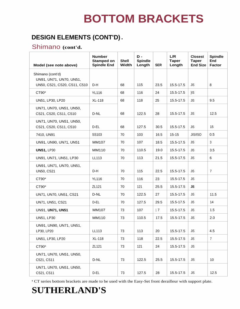
BOTTOM BRACKETSDESIGN ELEMENTS (CONT'D) .
Shimano (cont'd.
Model (see note above)
NumberStamped onSpindle End
ShellWidth
D -SpindleLength SER
L/RTaperLength
ClosestTaperEnd Size
SpindleEndFactor
Shimano (cont'd)
UN91, UN71, UN70, UN51,
UN50, CS21, CS20, CS11, C510 D-H 68 115 23.5 15.5-17.5 JIS 8
CT90* YL116 68 116 24 15.5-17.5 }IS
UN51, LP30, LP20 XL-118 68 118 25 15.5-17.5 JIS 9.5
UN71, UN70, UN51, UN50,
CS21, CS20, CS11, CS10 D-NL 68 122.5 28 15.5-17.5 JIS 12.5
UN71, UN70, UN51, UN50,
CS21, CS20, CS11, CS10 D-EL 68 127.5 30.5 15.5-17.5 JIS 15
7410, UN91 SS103 70 103 16.5 15-15 JIS/ISO 0.5
UN91, UN90, UN71, UN51 MM107 70 107 18.5 15.5-17.5 JIS 3
UN51, LP30 MM110 70 110.5 19.0 15.5-17.5 JIS 3.5
UN91, UN71, UN51, LP30 LL113 70 113 21.5 15.5-17.5 JIS 6
UN91, UN71, UN70, UN51,
UN50, CS21 D-H 70 115 22.5 15.5-17.5 JIS 7
CT90* YL116 70 116 23 15.5-17.5 JIS
CT90* ZL121 70 121 25.5 15.5-17.5 JIS
UN71, UN70, UN51, CS21 D-NL 70 122.5 27 15.5-17.5 JIS 11.5
UN71, UN51, CS21 D-EL 70 127.5 29.5 15.5-17.5 JIS 14
UN91, UN71, UN51 MM107 73 107 1 7 15.5-17.5 JIS 1.5
UN51, LP30 MM110 73 110.5 17.5 15.5-17.5 JIS 2.0
UN91, UN90, UN71, UN51,
LP30, LP20 LL113 73 113 20 15.5-17.5 JIS 4.5
UN51, LP30, LP20 XL-118 73 118 22.5 15.5-17.5 JIS 7
CT90* ZL121 73 121 24 15.5-17.5 JIS
UN71, UN70, UN51, UN50,
C521, CS11 D-NL 73 122.5 25.5 15.5-17.5 JIS 10
UN71, UN70, UN51, UN50,
CS21, CS11 D-EL 73 127.5 28 15.5-17.5 JIS 12.5
* CT series bottom brackets are made to be used with the Easy-Set front derailleur with support plate.
SUTHERLAND'S

SER denotes shell to end, right measurement.
See page 3-15 for further explanation.
BOTTOM BRACKETSDESIGN ELEMENTS (CONT'D.
StronglightThe bearings are pressed onto the spindle. 113,
118, 124, 133mm length spindles are available.
The dimensions of all Stronglight models are simi-lar. The model designations are as follows:600: All steel unit650: Titanium spindle, aluminum cups.
Chainline not adjustable.
651: Same as 650 except with steel spindle.700: Aluminum cartridge threaded at both ends for lockrings.
701: Same as 700 but full-length threads. Recommended for aluminum frames.
Currently only models 650 and 651 are being imported into the US.
Adjustable cups on both sides allow for minor chainline adjustments.
ModelShellWidth
D -SpindleLength SER
L/RTaperLength
ClosestTaperEnd Size
SpindleEndFactor
Stronglight
37/24 650 68 114 23 15/15.5 ISO 4.5
37/24 650 68 123.5 31.5 15/16.5 ISO 14
SUTHERLAND'S

BOTTOM BRACKETS
DESIGN ELEMENTS (CONT'D.
SuginoThe Maestro bottom bracket has adjustable cups on both sides with the 6903 bearings pressed
onto the titanium spindle. Both cups have 2.5mm recesses (but the recesses are only 23mm in
diameter, which is smaller than for Shimano super low profile cranksets).
The Guines bottom bracket is a cartridge unit. The retaining cups are installed with standard bot-
tom bracket tools. Though the left cup is adjustable, there is no need to adjust it for no load on
the bearings - just tighten it down so the cartridge is not loose.
The other Sugino bottom brackets have spindles with a shoulder, on only one side and the other
side is threaded. They also have two different cups: one with the bearing flush with the face ofthe cup, the other with a recessed bearing. Other pieces required are two Belleville springs, a
notched washer, a slotted nut and a spanner style nut. Installation: Thread both cups into the
frame. The cup with the flush-mounted bearing should be installed on the right side of the bike.
Use Sugino tool #214 to tighten both cups. Insert the spindle through the bearings from the right
side of the bike. Place the springs face to face so the outsides are touching and put them over the
end of the spindle on the left side of the bike. Loosely thread the slotted nut onto the spindle
behind the springs. The slotted nut should not be so tight as to completely compress the wave
spring, but tight enough so there is almost no side-to-side play in the spindle. Slide the notched
washer onto the spindle followed by the spanner style nut. Tighten the nut using the Sugino tool
- you may need to place a crankarm onto the spindle in order to be able to tighten the nut
enough. Check for play or drag in the spindle and tighten or loosen the slotted nut appropriately.
There is no chainl ine adjustability for either style bottom bracket.
ModelPartNumber
D -Shell SpindleWidth Length SER
L/RTaperLength
ClosestTaperEnd Size
SpindleEndFactor
SuginoMaestro BB-TiMA 69.5 111 21.5-23 15/15.5 JIS/ISO 5.5-5.7
MS 68 or 70 114.5 22 n/a ISO 3.5
MW, Guines 68 or 70 118.5 25.5 n/a ISO 7.5
SB 68 or 70 124.5 30 n/a JIS 14
RB 68 or 70 129 34.5 n/a JIS 17.5
RRB 68 or 70 136 36 n/a JIS 19
SUTHERLAND'S
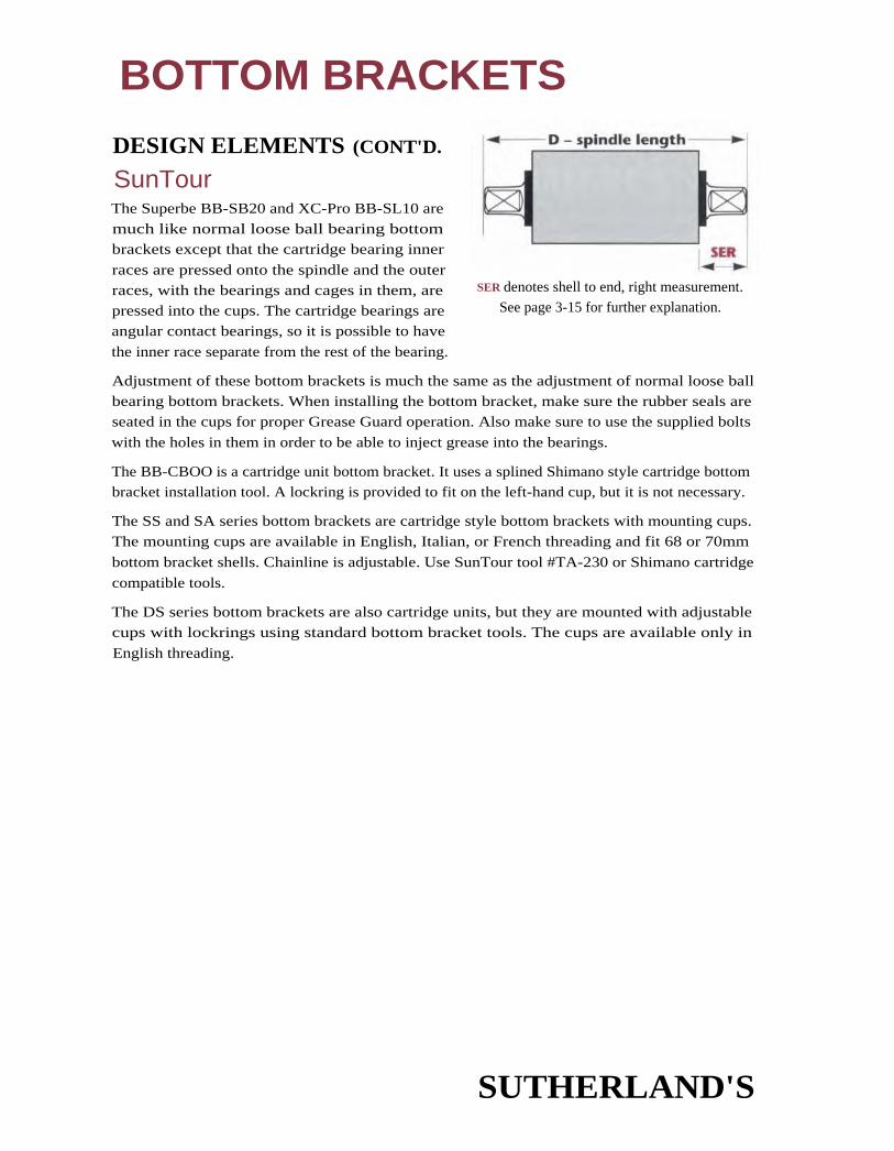
SER denotes shell to end, right measurement.See page 3-15 for further explanation.
BOTTOM BRACKETS
DESIGN ELEMENTS (CONT'D.
SunTourThe Superbe BB-SB20 and XC-Pro BB-SL10 are
much like normal loose ball bearing bottombrackets except that the cartridge bearing inner
races are pressed onto the spindle and the outer
races, with the bearings and cages in them, arepressed into the cups. The cartridge bearings are
angular contact bearings, so it is possible to have
the inner race separate from the rest of the bearing.
Adjustment of these bottom brackets is much the same as the adjustment of normal loose ballbearing bottom brackets. When installing the bottom bracket, make sure the rubber seals areseated in the cups for proper Grease Guard operation. Also make sure to use the supplied bolts
with the holes in them in order to be able to inject grease into the bearings.
The BB-CBOO is a cartridge unit bottom bracket. It uses a splined Shimano style cartridge bottombracket installation tool. A lockring is provided to fit on the left-hand cup, but it is not necessary.
The SS and SA series bottom brackets are cartridge style bottom brackets with mounting cups.
The mounting cups are available in English, Italian, or French threading and fit 68 or 70mm
bottom bracket shells. Chainline is adjustable. Use SunTour tool #TA-230 or Shimano cartridge
compatible tools.
The DS series bottom brackets are also cartridge units, but they are mounted with adjustablecups with lockrings using standard bottom bracket tools. The cups are available only in
English threading.
SUTHERLAND'S

BOTTOM BRACKETSDESIGN ELEMENTS (CONT'D.
SunTour (cont'd).
ModelShellWidth
D -SpindleLength SER
L/RTaperLength
ClosestTaperEnd Size
SpindleEndFactor
SunTour
MicroDrive Sport (BB-CB00) 68 115 22 1 7.5 JIS/ISO 6
Superbe (BB-SB20) 70 112 21 1 5.5/16 ISO 2.5
68 112 22 15 ISO 4
XC-Pro (BB-SL10-73) 73 119 23.5 17.5 jIS 8
SL/XC-Pro (BB-SL10) 68 115 24 1 7/16.5 JIS 8.5
SA-100, SS100 68 or 70 108 20 n/a ISO 3
SA-110, 55110 68 or 70 117 24.5 n/a ISO 7.5
SA-120, SS-120 68 or 70 120 29.5 n/a ISO 13
SA-130, SS-130 68 or 70 126 27 n/a ISO 10.5
SA-190, SS-190 68 or 70 117 28.5 n/a JIS 13
SA-160, SS-160 68 or 70 126 32 n/a PS 1 6.5
SA-140, SS-140 68 or 70 126 31 n/a JIS 15.5
55-150 68 or 70 131 32 n/a JIS 16.5
DS-200, DS-210 68 126 31 n/a JIS 15.5
DS-220, DS-230 68 131 31.5 n/a JIS 1 6.5
SUTHERLAND'S

BOTTOM BRACKETSDESIGN ELEMENTS (CONT'D .
SyncrosPro Series bottom brackets use 7mm-wide 61903 bearings pressed onto the spindle, and Hardcore
uses double row 10mm-wide INA bearings. The cups are interchangeable, but the spindles aredifferent for these two because of the bearing-width difference.
Dual adjustable cups can be used on different-width bottom bracket shells and provide some
chainline adjustment (depending on the bottom bracket shell width).
Three kinds of cups are available: recessed cups with Italian threading, recessed cups with Englishthreading, and flat cups. Use either recessed cups with shorter spindles (113mm or less) or super
low profile cranksets. Use the flat cups, which are available in English threading only and pro-vide better bearing support, with longer spindles.
If your bottom bracket shell is narrower than the shell width listed, you will have more adjusta-bility in the chainline, SER, and spindle end factor by the amount that it is narrower.
SUGGESTED SPINDLES FOR GIVEN CRANKARMS:
103 With recessed cups. For Dura-Ace SLP.107 With recessed cups. For Deore XT & LX Compact.108 With recessed cups. For XTR, Raceface Turbine LP and Cooks Bros. E.111 With recessed cups. All Campagnolo Road & Mountain 1990.113 With recessed cups. For '93 Deore LX, pre '93 Dura-Ace, Sugino Fuze, Topline
Road, and SunTour Microdrive (68mm).117 For most Syncros Mtn Triple, Ritchey, XT pre '94, SunTour Microdrive (73mm),
Grafton Mtn, and some Kooka.122.5 For most XT pre '94, most Kooka, some Syncros Mtn, Cook Bros. RSR and most
CBR, most Topline Mtn, Cooks, and Raceface Turbine.127.5 For XT pre '94, Cook Bros. RSR, and CBR, Topline Mtn, and most Cooks.131 For odd size cranks or cranks on wide clearance stays/swingarms.
Model
D -Shell SpindleWidth ' Length SER
L/RTaperLength
ClosestTaperEnd Size
SpindleEndFactor
Syncros
Pro Series 70 103 17 15.5 ISO 0.5
Pro Series/Hardcore 68.5 107 18 17 Univ. 4
73 108 17 16 Univ. -0.5
Pro Series 70.5 111 20.5 15.5 ISO 2
Pro Series/Hardcore 73 113 20.5 15.5 ISO 4
74 117 22 15.5 ISO 5.5
74 122.5 25 15.5 ISO 8.5
74 127.5 27.5 15.5 ISO 1174 131 29.5 15.5 ISO 13
SUTHERLAND'S
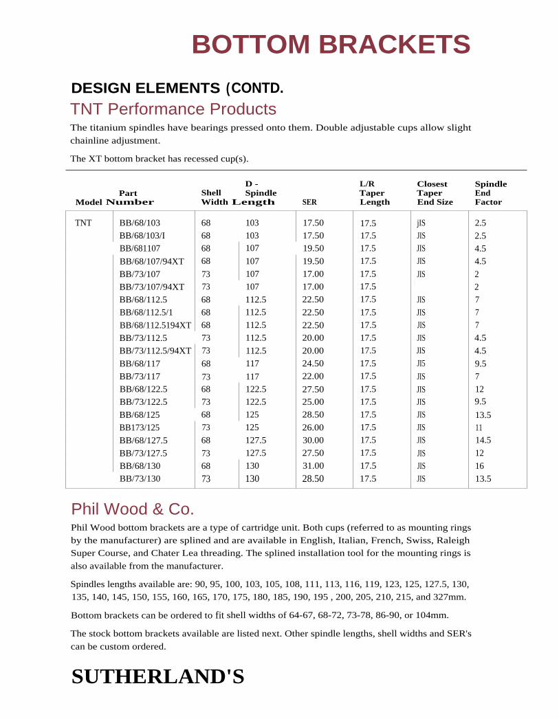
BOTTOM BRACKETS
DESIGN ELEMENTS (CONTD.TNT Performance ProductsThe titanium spindles have bearings pressed onto them. Double adjustable cups allow slight
chainline adjustment.
The XT bottom bracket has recessed cup(s).
D - L/R Closest SpindlePart Shell Spindle Taper Taper End
Model Number Width Length SER Length End Size Factor
TNT BB/68/103 68 103 17.50 17.5 jIS 2.5BB/68/103/I 68 103 17.50 17.5 JIS 2.5BB/681107 68 107 19.50 17.5 JIS 4.5
BB/68/107/94XT 68 107 19.50 17.5 JIS 4.5
BB/73/107 73 107 17.00 17.5 JIS 2BB/73/107/94XT 73 107 17.00 17.5 JIS 2
BB/68/112.5 68 112.5 22.50 17.5 JIS 7BB/68/112.5/1 68 112.5 22.50 17.5 JIS 7
BB/68/112.5194XT 68 112.5 22.50 17.5 JIS 7
BB/73/112.5 73 112.5 20.00 17.5 JIS 4.5
BB/73/112.5/94XT 73 112.5 20.00 17.5 JIS 4.5
BB/68/117 68 117 24.50 17.5 JI5 9.5
BB/73/117 73 117 22.00 17.5 JIS 7BB/68/122.5 68 122.5 27.50 17.5 JIS 12
BB/73/122.5 73 122.5 25.00 17.5 JIS 9.5
BB/68/125 68 125 28.50 17.5 JIS 13.5BB173/125 73 125 26.00 17.5 JIS 11
BB/68/127.5 68 127.5 30.00 17.5 JIS 14.5
BB/73/127.5 73 127.5 27.50 17.5 JIS 12
BB/68/130 68 130 31.00 17.5 JIS 16BB/73/130 73 130 28.50 17.5 JIS 13.5
Phil Wood & Co.Phil Wood bottom brackets are a type of cartridge unit. Both cups (referred to as mounting ringsby the manufacturer) are splined and are available in English, Italian, French, Swiss, RaleighSuper Course, and Chater Lea threading. The splined installation tool for the mounting rings is
also available from the manufacturer.
Spindles lengths available are: 90, 95, 100, 103, 105, 108, 111, 113, 116, 119, 123, 125, 127.5, 130,
135, 140, 145, 150, 155, 160, 165, 170, 175, 180, 185, 190, 195 , 200, 205, 210, 215, and 327mm.
Bottom brackets can be ordered to fit shell widths of 64-67, 68-72, 73-78, 86-90, or 104mm.
The stock bottom brackets available are listed next. Other spindle lengths, shell widths and SER's
can be custom ordered.
SUTHERLAND'S

D -Shell SpindleWidth Length
L/R Closest SpindleTaper Taper End
SER Length End Size FactorModel
JIS/IS0
JIS/IS0JIS/ISO
JIS/IS0
JIS/IS0
JIS/IS0JIS/ISOJIS/IS0
JIS/ISOJIS/ISO
JIS/ISO
JI5/IS0
J1S/IS0
JIS/IS0
JI5/ISOJIS/IS0JIS/ISO
JIS/ISO
.JIS/IS0JIS/IS0
JI5/IS0
JI5/IS0JIS/IS0JIS/IS0
Phil Wood 68
68
68
68
68
68
68
68
68
68
68
68
73
73
73
73
73
737373
737373
73
103
105
108
108
111
113
116
119
1 23
1 25
127.5130
103105
108113116119
123
125127.5130135140
1.5
2.54
4
5.5910.5
11.51415
16
15
-10
1.54
5.59.5
11.5
12.513.512.5
17.5
20
17.5
18.520
2021.52526.5
27.5
30
3132.2531
1516
1 7.520
21.5
25.5
27.528.529.75
28.533.5
36
18.5
18.5
18.52323
2323
2323
2323
23
18.5
18.518.5
232323
23
2323
232323
BOTTOM BRACKETSDESIGN ELEMENTS (CONT'D.
Phil Wood & Co. (cont'd)Available in stainless steel or titanium. The chainline can be adjusted 2.
Phil mounting rings can be used to mount Shimano Cartridge Brackets
mount Shimano Cartridge units in unusually threaded bottom bracketchainline more adjustable. Remove the Shimano cups using a vise and
SUTHERLAND'S
5mm in either direction.
. This makes it possible to
shells and also makes thea rubber mallet.

ENGLISH COTTERED SPINDLE INTERCHANGEABILITYThe following chart was compiled from five different sources. Numbers are rounded to the nearest 1/16" or .5mm. There may beminor discrepancies but none that should affect the interchangeability. Please write if you have any problems with the chart.
Spindles on the same line are interchangeable but may not have precisely the same dimensions. Spindles within
each center size category are arranged in order of increasing right side. In cases where the right side is the same,
they are listed in order of increasing left side.
Many of the spindles listed are no longer being made and are listed only so that replacements can easily be made. Hercules, Brampton,
Bayliss Wiley, and Phillips that have only the old stamping number are no longer manufactured.
Shadingindicatesmostcommonlyusedspindles.
Centers Left I Center I Right Total
1-11/16 1-5116 1-11/16 1.5;8 4-5/8 PBA 601 F103 C16/6 6 1 20 Miniature cycles(43.0mm) (34.0) (43.0) (41.5) (117.5)
1-15/16' 1.7/16 1-15/16 1-11/16 5-1/16 0 6/7 7 1(49.0mm) (36.5) (49.0) (43.0) (129.0)
2-1/16" 1-5/16 2-1/16 1-5/16 4-11/16 PBA604 1102 15 single chainrings(52.5mm) (33.5) (52.5) (33.5) (119.0)
1-5/16 2-1/16 1-3/8 4-3/4 06/2 2(33.5) (52.5) (35.0) (121.0) 519/2
1-5/16 2-1/16 1-7/16 4-13/16 PBA 510 F122 C16/9 9 23R 5-speeds(33.5) (525) (36.5) (122.0) 519/9
1-5/16 '1!16 7-5/8 5 PBA512 3900431 i 01 14 MC34 88A280 3758(33.5) .!.5) (41.5) (122.0)
1-5/8 2-1/16 1-5/8 5-1/4 F'BA506 1139 8(41.5) (52.5) (41.5) (133.5)
1-5/16 2-1/16 1-11/16 5-1/16 PBA504 F113 0 6/4 4 4 1 0-speeds(33.5) (52.5) (43.0) (129.0) 519/4
1-3/8 2-1/16 1-3/4 5-1/4 PBA513 3900437 F109 C16/5 5 2C MC3GC BBA261 3759(35.0) (52.5) (44.5) (133.5) 519/5 1
2-3/16- S/16 2-3/16 1-7/16 4.15/16 RBA104 A16 16 C16/10 10(55.0mm) 3 5) (55.0) (36.0) (126.0)
5/16 2-3/16 1-9/16 5 RBA103 A23 23S3.5) (55.0) (393) (127.0)
1-11/32 2-3/16 1-13/16 5-11/32 RBA105 Al 6GC 16GC C16/11 11 3760 Raleigh 1,3,5(34.0) (55.0) (46.0) (135.0) most 10-speeds
1-5/8 2-3/16 1-7/8 5-11/16 RBA102 22 22 Raleigh Tandem(39.0) (55.0) (47.5) (144)
2 . 7/16" , 7/32 2-7/16 1-3/4 5-7/16 RBA108 A8 08GC R16/8 8 AEG R 3757 R51.N 16, Tourist{32.0) (62.0) (44.5) (137.0)
1-7/16 2-2/16 1.3/4 5-5/8 RBA101 A21 21GC PBA508 3900709 F104 12 Chopper, Twenty(36.0) (62.0) (44.5) (148.0)
1-11/16 2-7/16 1-11/16 5 . 1/2 R16/14 14 3 Delivery (Carrier)(410) (62.0) (43.0) (142.5)

BOTTOM BRACKETSCOTTERED BOTTOM BRACKET SPINDLESSpindle End Diameter
Nominal Actual
ISO* 16mm 15.9mmEnglish 5/8" (15.88mm) 15.75-15.8mmFrench 1 6mm 15.9mm
Italian 16mm 15.9mm
* (See Appendix for mor e detail om ISO standards.)
FRENCH COTTERED SPINDLESFrench bottom bracket spindles are catalogued by overall length.
OverallLength Left Center Right
Markingson Spindles
Gitane—all black
1 30 33 56 41 none
134 35 56 43 none
138 35 56 47 none
Motobecane—all black
1 34 36 55 43 none
1 36 35 56 45 none
138 35 56 47 none
Notes
Original equipment on Motobecane until '74,used with Solida cranks.Original equipment on Motobecane from '74,used with Solida and Nervar cranks.For Nervar cranks on Gitane and other French bikes.
Peugeot*—black ends, unpolished middle, polished left and right sides1 40 42 55 43 none
1 42 42 55 45 none Original equipment to fit folding bike.
145 43 55 47 none OrigInal equipment to fit U08, A08, A018, U018C.
RFG—marked RFG135 37 54 44 13554C
137 37 54 46 13754C
140 40 54 46 140 54C
135 (see note) 68 135 Original equipment on Sutter and other French
bikes. Balls run in grooves on spindle, cups are
extra thick and not interchangeable with others
* Peugeot spindles and cups are not interchangeable with others.
SUTHERLAND'S

BOTTOM BRACKETS
ASSORTED OTHER COTTERED SPINDLES
*
OverallLength Left Center Right
Markingson Spindles
GERMAN — (not interchangeable with others)
RFG 135 36 56 43 1 70
Steyr 1 42* 40 56 46 none
(Puch) 1 35** 38 56 41 none
ITALIAN
Magistroni 1 27 33 56 38 Magistroni 5R
Ofmega 1 37 44 58 35 Made in Italy
RFG 136 36 57 43 136
JAPANESE
145 41 51 43 No. 1
139 40 53 46 S
146 42 53 51 S3
1 43 41 53 49 U3
1 43 41 54 47 ST
1 39 35 55 49 LB
13.5 35 55 45 ITAZAM
138 35 57 46 57
140 33 62 43 A-8***
For Clubman and 10-speeds.
** For 1- and 3-speeds.
***Similar to Raleigh A-8.
SUTHERLAND'S

BOTTOM BRACKETSTHOMPSON (THUN) BOTTOM BRACKET SETSFor Bottom Bracket Shells (inside diameter by width)
40 x 65, 40 x 70 45 x 65, 45 x 70 30 x 65, 30 x 70
Axle Diameter 5/8" (15.8mm) 5/8" (15.8mm) 13mm (.511")
1 Length 5-1/2" (140mm) 5-1/2" (140mm) 137mm (5-1/4")
Ball Size 1/4" 5/16" 3/16"
Cotter Size 3/8" (9.5mm) 3/8" (9.5mm) 8mm
Locknut Size 26mm (1.02") 26mm (1.02") —
Adjustable left side is left-threaded. Be sure that the indentations in the left dust cover line
up with the slot in the cone. Tighten locknut by holding crank arm on other side. Leave the
cone on the right side in place.
ONE PIECE (ASHTABULA) CRANKS
Thread Sizes and Ball RetainersRight-threaded Left-threadedRight Side Left SIde(Stationary Cone) (Adjustable Cone) Retainer
USA 15/16" x 24 TPI 7/8" x 24 TPI 66 1 0 - 5/16"
Ball Numberand Size
Schwinn 15/16" x 28 TPI 7/8" x 28 TPI 64 9 - 5/16"
SUTHERLAND'S

4CONTENTS
Hub ShellBall sizes ...................................... 2
Thread sizes ................................. 2
FreewheelsInterchangeability ....................... 2
Body markings ............................ 3
Hub markings ............................. 3
Spacers ......................................... 4
Mounting .................................... 4
Problems to avoid ....................... 4
Removing freewheels ................. 5
About removing tools ................ 5
Freehubs - Cassette CogsRemoving ................................... 6
Mounting .................................... 6
Freewheels and Freehub(Cassette) ToolsRemoving tools ..................... 7-11
Cassette sprocket removal ......12
Cassette body removal ............ 1 2
Sprocket replacement .............. 12
Freewheel sprocket removal ... 12
Interchangeability ChartsHow to use charts .................... 1 3
Campagnolo ....................... 14-16
Cassette body lengths .......... 1 6
Freewheel sprocket chart ...... 1 6 1 6
Mavic cassettes ......................... 17Cassette body lengths .......... 1 7
Sprockets and spacers ......... 1 7
Regina sprocket chart ........ 18,20
Regina spacer chart ........... 1 9,21Spacer dimensions ................ 21
TD Cross, Regina and Atom
threaded ......................... 22-23
Sachs, Maillard: ArisFreewheel sprocket chart ......24 24Spacer chart ......................... 25
Maillard, Atom 77, Sachs-HuretFreewheel sprocket chart ...... 26 26Spacer chart ......................... 27
Shimano Hyperglide
Cassette sprocket chart ........ 28
Cassette spacer chart .....29-30Sprocket thru bolts ............... 30Cassette spacer dimensions . 31
Cassette body lengths .......... 31
Shimano Non-HyperglideCassette sprocket chart ........ 32
Cassette spacer chart .......... 33
Shimano, Normandy, SchwinnFreewheel sprocket chart ...... 34
Shimano freewheelSpacer chart ......................... 35Spacer dimensions ................ 35
SunTourCassette sprocket chart ........ 36Cassette spacer chart .......... 37Cassette body length ........... 37
SunTour PowerfloFreewheel sprocket chart ...... 36Freewheel spacer chart ........ 37
SunTour AccushiftFreewheel sprocket chart ...... 38Freewheel spacer chart 40
SunTour other ................... 42-45
SunTour Non-AccushiftSprocket chart ................... 46
Cyclo sprocket chart ........ 47
Caimi, Everest, Simplex 48
Single-speeds, fixed gear 49
SUTHERLAND'S

FREEWHEEL, FREEHUB, FIXED GEARS
MULTI-SPEED FREEWHEEL—HUB SHELL
Ball Sizes 1/8"
Counting freewheel halls is a waste of time. It is better to use one or two too few balls than too many.
Thread SizesISO* 1.375" x 24 TPI (34.92mm x 1.058mm)
English 1.370" x 24 TPI (34.80mm x 1.058mm)
French 34.7mm x 1mm (1.366" x 25.4 TPI)
Italian 35mm x 24 TPI (1.378" x 1.058mm)
Country of manufacturer does not indicate thread dimensions.
During the 70's and 80's most freewheels imported into this country had English threads.
English, Japanese and USA bicycles generally came with English threaded freewheels. French
bicycles generally come with French threaded freewheels; however, later Peugeots and some
others use English threaded freewheels. Italian bicycles generally used Italian threaded free-wheels. Recent Italian bicycles use ISO or English threaded freewheels.
Stop and measure before forcing a freewheel.
A check with a thread pitch gauge will separate French from Italian and English threads.English and Italian huh threads cart be distinguished by measuring with a vernier caliper. A two-
inch micrometer, however, is the preferred tool. This method may not work on some hubs.
FREEWHEEL INTERCHANGEABILITY
ISOHub
EnglishHub
FrenchHub
ItalianHub
ISO Freewheel A A C** A
English Freewheel A A C** B***
French Freewheel C** C** A C**
Italian Freewheel A B*** C** A
Class of FitA Made to fit.B Will fit and be serviceable but will damage threads slightly.
C Looks like it might work but won't.
* See Appendix for more details on ISO standards.** Difference in thread pitch makes this combination unacceptable.
*** This combination works, but avoid changing back and forth betweenItalian and English freewheels. Not for strong or heavy riders.
SUTHERLAND'S

FREEWHEEL, FREEHUB, FIXED GEARS
I D MARKINGS ON FREEWHEEL BODIESMarkings on freewheel bodies are only found on some models.
AtomEnglish rectangular punch mark on back of body
French no mark
MaedaEnglish no markFrench M stamped in inner ring of body on outside
Maillard—see Atom
Normandy —see Atom
ReginaOld Marking
English F.I. stamped in back
French F.F. stamped in backItalian nothing stamped in back
Current Marking
ISO 3 grooves in backEnglish 1 groove in back
French 2 grooves in back
Italian no grooves in back
ZeusEnglish B stamped in back
French M stamped in back
I D MARKINGS ON HUBSCampagnoloOld Marking—between spoke hole flange and freewheel threading
English 1 grooveFrench no groove
Italian no groove
Current Marking—marked with thread size
Ofmega—marking between spoke hole flange and freewheel threading
English 1 groove
French 2 grooves
Italian no grooves
ZeusEnglish B.S.C. stamped on center shaft of the hub
French nothing stamped on center shaft on the hub
SUTHERLAND'S

FREEWHEEL, FREEHUB, FIXED GEARS
FREEWHEEL SPACERS(Between hub and threaded or freewheels)
Bicycle Research 1, 1.5, 2mmCampagnolo 1, 1.5, 2mmSturmey Archer HMWI27 1/16" (1.6mm)RaleighCyclo (French)
1/32" (.8mm),1.2, 1.7mm
1/8" (3.2mm)
Wheels Manufacturing 1, 1.5, 2mm
MOUNTING FREEWHEELS
Factors to Consider1. Hole in freewheel has to be large enough to lit over locknuts of hub.
2. Before you put it on, make sure you can remove it. (See "Problems to Avoid" below.)
3. Match the threads with the hub.
4. Be aware of any chainline changes. Note the offset differences on the freewheel back.(See hub section on page 10-5.)
5. Check outside clearance, especially clusters with outside chainguards. Will they clearseat stay, chain stay and derailleur mounting bolt?
6. Be sure faces of freewheel and hub that butt together are compatible, i.e. ReginaScalare (close ratio) has a recessed face that may not butt properly on some hubs.
7. Is a new chain necessary?
Problems to AvoidDon't use an old style Shimano splined freewheel on Campagnolo, Shimano Dura Ace or similarhub. It comes off only after removing axle from other side.
Mount splined Atom, Zeus, or Regina to a Campagnolo or similar hub only if you have a thin wallAtom tool like the Phil Tool.
Before installing a freewheel on a sealed bearing hub, be sure you can get it off. Atom-typesplined freewheels can only be removed with a thin wall tool or by disassembly.
Old style Shimano splined freewheels must he disassembled to he removed from Phil, Hi-E,Weyless, and other sealed hearing hubs.
Always remove the freewheel before cutting the spokes out of a wheel.
12mm tandem axles are too big for the holes in many freewheel pullers. Current BicycleResearch tools have clearance for 12mm axles.
SUTHERLAND'S

FREEWHEEL, FREEHUB, FIXED GEARS
REMOVING FREEWHEELS
Factors to ConsiderFit for notch tools:
1. Tools must be in good shape
2. Dogs must closely fit notches
3. Tool must butt against body, not bottom of notch
4. Tool must he properly located against body or axle or both, to ensure the dogs stay
properly engaged when force is applied
5. Tool must be secured with quick release or axle nut to break freewheels loose
6. With remover clamped in a vise, press down at rim while turning to remove
Dogs that are too long prevent the rim from seating on the body. This allows the remover to
rock and the dogs to climb up and strip the body.
If stripped, chisel off the chewed-up part on a Regina notched-type freewheel. Often it will chip
off square. Then start again.
Freewheel Removing ToolsCombinations of freewheels and pullers are listed as "A", "B", or "B-". An "A" fit is probably themost successful combination and, if properly secured and located, won't result in any damage to
the freewheel or tool. With a "B" fit there is some chance of damage to the freewheel and tool. A
"B-" fit is more likely to damage both tool and freewheel; but if you have to remove freewheel tothrow it out, it might be worth it.
Not all combinations that work are listed. If you try others, be sure to follow recommendations
listed under "Factors to Consider."
If all else fails, you can remove a freewheel by dismantling it. Exceptions to this are the old
style Winner.
SUTHERLAND'S

FREEWHEEL, FREEHUB, FIXED GEARS
REMOVING FREEHUBS - CASSETTE COGS
Factors to Consider1. Most current cassettes have all cogs splined and are held on with a lockring threaded
into the freehub body.
2. Older cassettes have the smaller one or two cogs threaded onto the freehub body.These are removed much like sprockets are removed from freewheels: with two chain
whips. Check the sprocket interchangeability charts to see which cogs are splined andwhich are threaded.
3. Tool can be held in place with quick release or axle nut to break cassette loose if necessary.
4. Some freewheel tools may be used to remove cassette lockrings. Be careful when usingthem. Because they are designed for freewheels, they are longer than they need to be
for cassettes and may press the inside seals against the freehub bearings.
MOUNTING FREEHUBS - CASSETTE COGS
Factors to Consider1. Because lockrings are not tightened by pedaling forces, be sure to torque the lockrings
when installing them, but do not overtighten them either.
2. See also individual sections on cassette cog interchangeability.
3. Grease the threads on the lockring or any threaded cogs and make sure enoughthreads engage the cassette body.
4. Be sure the sprockets are aligned on the cassette body (if necessary).
5. Check the sprockets for play that would indicate that the top sprocket is not seatedproperly.
6. Make sure the largest cog is spaced far enough away from the hub flange that the rear
derailleur does not hit the spokes when shifting into the largest cog.
7. If there are any rivets or bolts holding the sprockets together, make sure they are notcontacting the freehub body, especially if the freehub body is aluminum.
SUTHERLAND'S

FREEWHEEL, FREEHUB, FIXED GEARS
TOOLS FOR REMOVING FREEWHEELS AND FREEHUBSMake Class of Fit—Tool Notes
ATOM- splined
- notched
CAIMIEVERESTSIMPLEX
A Atom (splined)Bicycle Research
CT-1 AtomPark FR-4Phil ToolVar 407, 401Zeus (splined)Regina 805032
B Var 186Var 01
B- Bicycle ResearchCT-1 Regina
B Bicycle ResearchCT-1 Regina
Campagnolo 704Kingsbridge 101Shimano Dura-Ace
(new style)
B- Cyclo (English)Kingsbridge 100Shimano Dura-Ace
(old style)Var 186Var 188Var 01
With Phil or Park Tool, removing axlespacers is not necessary. Be sure tool iswell seated. Keep a sawed-off one forhubs that don't allow tool to seat fully.
Atom-style splined removers are not allthe same size due to tolerances. Keepseveral around to match differentfreewheels. Too loose a fit or one thatdoesn't go in all the way can causetrouble.
CAMPAGNOLO -FREEWHEEL
A Campagnolo 0520/40Kingsbridge 115Var 404Bicycle Research CT-9
CAMPAGNOLO -FREEHUB
- Sprocket lockring
- Freehub
A Campagnolo 71 30036Var 414B, Park BBT-5
B Shimano tools or PamirHypercracker
Tool also fits Campy bottom bracketcassette.
Loosen set screw in axle nut. Loosen axle nut. Ifpawls and springs pop out use Campy tool thatcomes with hub to reinstall the cassette body.
CYCLO (English)
CYCLO (French)
A Cyclo (English)Kingsbridge 100
A Cyclo (French) DR.64
B Kingsbridge 100Var 188
French and English Cyclos arecompletely different.
French Cyclo tools will fit over thelarge locknuts found on NewStar hubs. English and FrenchCyclos are completely different.
SUTHERLAND'S

FREEWHEEL, FREEHUB, FIXED GEARS
TOOLS FOR REMOVING FREEWHEELS AND FREEHUBS (CONT'D)
Class of Fit—Tool NotesMake
CYCLO-PANS (French) A Use tool that comeswith the freewheelDR.68, DR.P
Modify SunTour tool to work by filingthe outside of the dogs.
A Lifu 09B.1 Note: the regular 22.4mm O.D.splined tool will not work. Original Falconhad a hole so small Shimano 22.4mm O.D.splined tool had to bepounded in, whichruins the tool. Current Falcon freewheels havean oversized 23,6mm O.D. hole that willdamage a regular Shimano tool.
FALCON
MAEDA (See SunTour)
MAILLARD,SACHS-HURET
- notched Aris, 700 A Maillard 409, 410 & 411 411 has a special skewer.Kingsbridge 110Var 413
B- Shimano Dura-Ace(old style)
Var 186
(See Atom splined)
A Var 412 large diameterremover with 6 bumps
A Maillard 415 wrenchVar 524 wrench
Remove ring with special wrench,then pull freewheel off.
- splined (old)
- large-diameter holewith 6 slots
- Helicomatic
MERVEILLE A Eldi BGMVar 187 B
B Regina single-speed removerVar 01
A Two 5mm alien wrenches
Threads that mate with the hub gostraight through. You will have toremove the two smallest sprocketsbefore using the Eldi tool. Var 01 mayhave to be filed slightly to match.
MAVIC - FREEHUB
- Cassettes
- Sprocket lockring (See ShimanoHyperglide lockring)
Remove axle cap with alien wrenches.
MILREMO- splined- Pans
- 2 notch
(See Atom splined)(See Cyclo Pans)(See Atom notched)
NORMANDY A Bicycle ResearchCT-3 Normandy
Maillard 408Var 405
SUTHERLAND'S

SCHWINN Approved (See Atom splined or Shimano Pre-'85 splined for small-diameter internal splined cogs.)
(See Normandy for large-diameter internal-splined cogs.)
(See Sun Tour or Atom for notched cogs.)
SHIMANO Freehub
Tool works like a gear puller. Forpressed-on freehub-type body foundon 600AX, AX, 600 EX 7-speed.(Pre '85).
- Freehub for pressedon freewheel body
A Shimano Freehubremoval tool(TL-FH 30)
- Freehub Dura-Ace,Dura-Ace EX
- Freehub freewheelbody held on withhollow bolt
A Shimano Freehub tool(TL-FW10)
Remove axle.
Bolt-like tool
A 10mm alien wrench
- Freehub on steelhub shell
Not removable
- Hyperglide sprocketlocknut
A Shimano TL-HG15Bicycle ResearchPark FR-5Pamir Engineering
B CT-6 Shimano
Class of Fit—Tool NotesMake
A Regina 805032Park FR-4Phil Atom ToolVar 401
(See also Atom splined)
A Bicycle ResearchCT-1 Regina
Kingsbridge 101Shimano Dura-Ace
(new style)
B Kingsbridge 100
B- Cyclo (English) (some)Var 01Var 186Var 188
Campagnolo adapter (704/1) for 13-tooth cogs and 6-speeds lacks the ringthat prevents sideways slippage. TheCampagnolo #1 remover can be modifiedto fit a freewheel with 13 teeth bygrinding off the outside dogs. Thismodification means you can't turn theremover block over when it becomesworn or use it for single speed sprockets.Bicycle research fits 12-tooth Regina.
REGINA
- splined
- notched
SACHS-HURET (See Maillard)
SACHS
- Aris splined freewheel
- Sachs cassette body
A Any Shimano-style Post-'85splined tool.
A Sachs Cassette Body Tool(U500400) and 32mmwrench
Narrow side of double threaded piece is for7-speed. Wider threaded side is for 8-speed.Use mallet with tool threaded in cassette toreinstall.
FREEWHEEL, FREEHUB, FIXED GEARS
TOOLS FOR REMOVING FREEWHEELS AND FREEHUBS (CONT'D)
SUTHERLAND'S
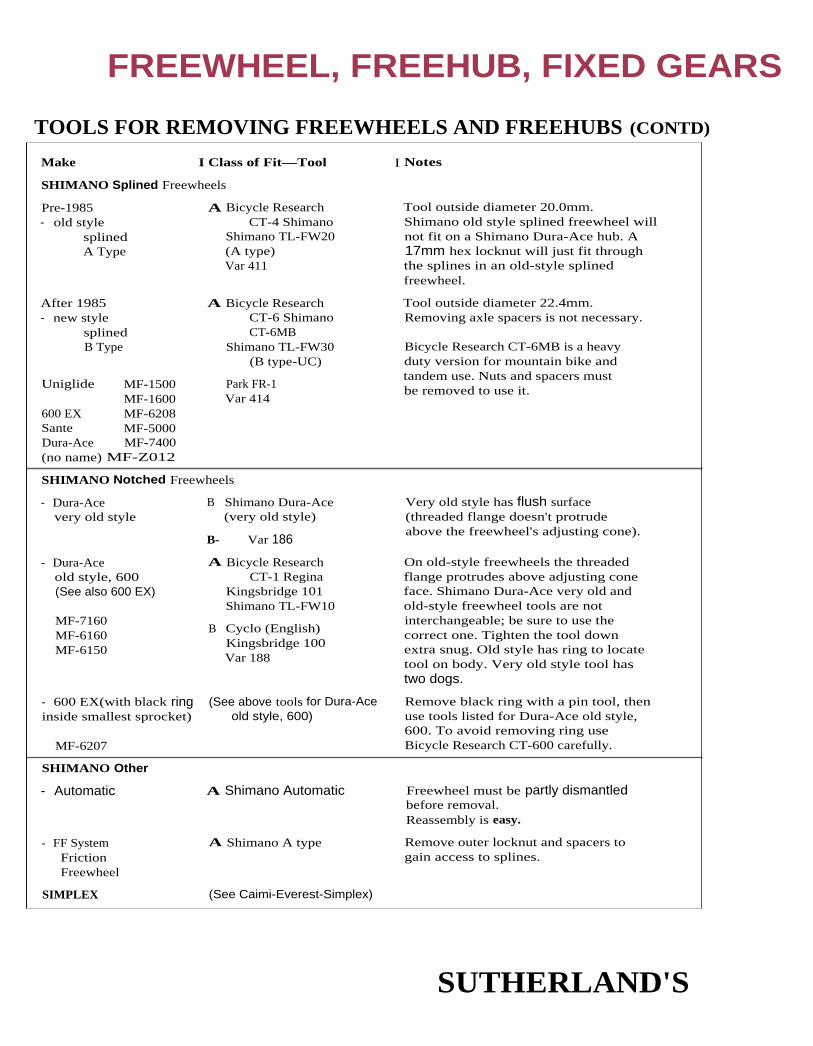
Tool outside diameter 20.0mm.Shimano old style splined freewheel willnot fit on a Shimano Dura-Ace hub. A17mm hex locknut will just fit throughthe splines in an old-style splinedfreewheel.
Pre-1985- old style
splinedA Type
A Bicycle ResearchCT-4 Shimano
Shimano TL-FW20(A type)Var 411
After 1985- new style
splinedB Type
Uniglide MF-1500MF-1600
600 EX MF-6208Sante MF-5000Dura-Ace MF-7400(no name) MF-Z012
A Bicycle ResearchCT-6 ShimanoCT-6MB
Shimano TL-FW30(B type-UC)
Park FR-1Var 414
Tool outside diameter 22.4mm.Removing axle spacers is not necessary.
Bicycle Research CT-6MB is a heavyduty version for mountain bike andtandem use. Nuts and spacers mustbe removed to use it.
(See above tools for Dura-Aceold style, 600)
- 600 EX(with black ringinside smallest sprocket)
MF-6207
Remove black ring with a pin tool, thenuse tools listed for Dura-Ace old style,600. To avoid removing ring useBicycle Research CT-600 carefully.
Very old style has flush surface(threaded flange doesn't protrudeabove the freewheel's adjusting cone).
On old-style freewheels the threadedflange protrudes above adjusting coneface. Shimano Dura-Ace very old andold-style freewheel tools are notinterchangeable; be sure to use thecorrect one. Tighten the tool downextra snug. Old style has ring to locatetool on body. Very old style tool hastwo dogs.
- Dura-Acevery old style
- Dura-Aceold style, 600(See also 600 EX)
MF-7160MF-6160MF-6150
B Shimano Dura-Ace(very old style)
B- Var 186
A Bicycle ResearchCT-1 Regina
Kingsbridge 101Shimano TL-FW10
B Cyclo (English)Kingsbridge 100Var 188
Make I Class of Fit—Tool I Notes
SHIMANO Splined Freewheels
SHIMANO Notched Freewheels
SHIMANO Other
- Automatic
- FF SystemFrictionFreewheel
SIMPLEX
A Shimano Automatic Freewheel must be partly dismantledbefore removal.Reassembly is easy.
A Shimano A type Remove outer locknut and spacers togain access to splines.
(See Caimi-Everest-Simplex)
FREEWHEEL, FREEHUB, FIXED GEARS
TOOLS FOR REMOVING FREEWHEELS AND FREEHUBS (CONTD)
SUTHERLAND'S

(Maeda)Winner, Winner-Pro,and a - 4 notch
A Bicycle ResearchCT-10
Park FR-3SunTour TA-320
Bicycle Research has reinforced dogs.
MicroLite - 6 notch A SunTour MicroLite (6 dog)
Perfect Pro Compe, A Bicycle Research8.8.8. and New Winner CT-7 SunTour
Kingsbridge 111- 2 notch SunTour (2 dog)
Var 706Park FR-2
B Cyclo (English)- some
Bicycle Research or Kingsbridge toolcan be used without removinglocknuts and without quick release tohold it in place. Use vice and pressdown at rim while turning. SunTourtool will not fit on 6- or 7-speedfreewheels. (2 notch)
- 4 notch(old) A SunTour (4 dog) (old)
B- Maillard 700Var 413
Make Class of Fit—Tool Notes
SUNTOUR Notched
SUNTOUR Freehub
- Pre-1991,not removeable
- 1 991 - current Remove axle; insert hex wrenchthrough hub from left side.
10mm allen wrench
TDC - 3 or 4 notch
- 4 notch
A Bicycle ResearchCT-5 TDC
TDCVar 402
A Bicycle ResearchCT-5 TDC
TDCVar 402
B Var 01Var 186
A Bicycle ResearchCT-2 Atom
Park FR-4Phil ToolVar 401Var 407Zeus (splined)
ZEUS 2000
FREEWHEEL, FREEHUB, FIXED GEARS
TOOLS FOR REMOVING FREEWHEELS AND FREEHUBS (CONT'D)
SUTHERLAND'S

FREEWHEEL, FREEHUB, FIXED GEARS
Cassette Sprocket RemovalAll SunTour cassettes and Shimano pre-Hyperglide cassettes have threaded outer cogs. The last
cog is threaded onto the cassette body except for the SunTour Microdrive cassettes where theouter cog is threaded onto the next cog in and that cog is threaded onto the cassette body. These
cogs are removed the same as with a freewheel on the wheel: with two chain whips. One toloosen the outer cog and one to hold the cassette body position.
Most other cassettes have all splined cogs and are held on by an externally threaded lockring
that threads into the cassette body. The lockring is removed with the appropriate removal tooland with a chain whip holding the cassette in place.
Cassette Body RemovalThere are many ways manufacturers attach cassette bodies to hubs. Some cassette bodies are
pressed on, some are bolted on, some are not removable. If the cassette body is removable usual-ly the wheel axle needs to be removed from the hub in order to remove the cassette body.
(See Tools For Removing Freewheels and Freehubs, on page 4-7 to 4-11, for specialtools needed to unbolt the cassette bodies.)
Many smaller manufacturers make hubs that use a Shimano-style cassette body. Sometimes thecassette bodies are made by Shimano so they are removed the same. Other times the cassettebodies are made by other manufacturers and removal varies.
Sprocket ReplacementWhen installing a new chain, you should also replace any worn sprockets because the new chain
may not run or shift smoothly on sprockets that have worn with the old, stretched chain.Depending on how much the old chain stretched, either only the high wear cogs (usually thesmaller cogs) or all the cogs may need to he replaced.
Freewheel Sprocket RemovalModern freewheels have splined inner sprockets held in place by threaded outer cogs. This
allows easy removal of all sprockets, even with the freewheel in place on the rear wheel.Removing the sprockets from an older, all threaded freewheel body is different. One or two of
the larger sprockets are left threaded and remove from the inside, the rest are right threaded andremoved from the outside. Do not attempt to hold the bare freewheel body when removing thelast threaded sprocket. Instead, thread two sprockets and lock them against each other (like a
cone and locknut), not against the freewheel body shoulder. Use this pair of sprockets to holdthe freewheel while loosening the last sprocket.
SUTHERLAND'S

FREEWHEEL, FREEHUB, FIXED GEARS
HOW TO USE THE INTERCHANGEABILITY CHARTSHorizontal rows represent freewheel models and vertical columns represent sprocket positions
(1 inside to 7 outside).
Sprockets inside each outlined box are interchangeable with one another. One-way inter-
changeability is indicated by an arrow crossing a heavy line. Restricted interchangeability is
indicated by a dotted arrow (if one-way) or by a dotted line (if two-way) and is explained in a
lettered footnote.
One-way Interchangeability
Restricted Interchangeability (One-way)
Restricted Interchangeability (Two-way)
For each sprocket listed, the manner in which it attaches to the cluster is indicated. Also indi-
cated is any provision a sprocket may have to hold the next smaller sprocket. The following
symbols are used:
To accept nextTo attach to cluster, smaller sprocket,
Symbol sprocket has: sprocket has:
Splines
Inside threads(left-handed)
Inside threads(right-handed)
Outside threads
(right-handed)
Inside threads(right-handed)
Inside threads(right-handed)
Outside threads(right-handed)
Inside threads
(right-handed)
Inside threads,same diameter
Inside threads,
lesser diameter
Inside threads
Outside threads
Arrow indicates the direction of sprocket removal. Note that splined and right-threaded sprock-
ets always come off to the right (outside) of the cluster, left-threaded sprockets come off to the
left (inside).
SUTHERLAND'S

FREEWHEEL, FREEHUB, FIXED GEARS
CAMPAGNOLO CASSETTESCampagnolo Pre '94 Cassettes:Pre '94 cassettes come in three levels of quality: Aluminum, Steel Record, and Steel Athena.
The cogs come in three series: A for the outer cog (with built in spacer), B cogs for the middle (the
aluminum is only available in the B series), and C cogs for the inner position(s). C cogs are designednot to shift to a smaller cog while hack pedaling especially given the chainline in those positions.
The A cog is only for the outer position. The B cog is for anything but the outer position. The C cogsshould only be used on the inner positions, there should also be no B cog larger than the smallest C.
The 1993 and earlier series of cogs were a symmetric 8 notch cog and cassette body. The B and C seriescogs had the letters A through H successively labeled clockwise on their cogs. Special alignment of
these cogs is important for best shifting performance due to the different tooth profiles on the cogs.
Look to the chart to see the alignment of the cogs.
Reading the Cog Alignment Chart:For any two cogs next to each other, look up the larger one on the bottom line, look up the smaller onthe right side of the chart, find the intersection of the two cogs. That letter should be the letter on the
smaller cog directly above the A' stamped on the larger cog. (The letters on the cogs should face out.)
The orientation of the smallest cog (the A series cog) does riot matter. If the smallest cog is an11-tooth cog, use the special lockring (part #7203085) to hold the cassette on, otherwise use thenormal lockring (part #7203084).
SUTHERLAND'S

FREEWHEEL, FREEHUB, FIXED GEARS
Campagnolo Exa-Drive Cassettes and Bodies:1994 Campy cassettes use sprockets with eight dogs. One of the dogs is narrower than the oth-ers. The cassette body has eight grooves with one narrower than the other. That means that the
1994 cassette sprockets will work on any of the cassette bodies, but 1994 cassette bodies can only
use 1994 cogs (earlier cogs will not fit). 1994 cogs should not be mixed with earlier cogs.
Currently there are three sequences of cogs: the A, B, and C sequence of cogs. (Not related to Pre-
'94 A, B, and C series sprockets.)
Choose any eight cogs, from the chart below, that form a continuous path from the left to theright. Sprockets can only he used in order. B and C sequence cogs should never be mixed.
Exa-Drive A, B, and C series cogs have no correspondence to non Exa-Drive A, B, or C series cogs.
Example: B12, B13, B14, B15, B16, B17, B19, B21, B23 will work but B12, B13, B14, B15, A17,
B19, B21, B23 will not work.
These cogs are marked with either a triangle or diamond at the narrower dog, so when installingon a pre-'94 cassette body, he sure to have these aligned. The circles on the face of the cogs
should form a smooth spiral.
Campagnolo tool #7130036, Var 414B or Park BBT-5 should be used to tighten the lockring to 50
Nm or 37ft. lbs. for all the cassettes.
SUTHERLAND'S

spline(length
overlocknut dimension —
SpeedsFreehub BodySpline Lengths*
OverlocknutDimensions
CAMPAGNOLO7-speed
8-speed
30.5
34.6
126
130
FREEWHEEL, FREEHUB, FIXED GEARS
FREEHUB (CASSETTE) BODIES — LENGTHS
* There is no external threaded section on Campagnolo freehubs.
CAMPAGNOLO SPROCKET INTERCHANGEABILITY
Notes:Spacer © is used between sprockets (B) and (DE). For the 7-speed an additional spacer is neededbetween sprockets 3 and 4. Early models combined sprockets (A) and (B) into sprocket (AB). If a16-tooth sprocket was used in the second position, this required spacer (C2) to be used between
(AB) and(DE).
SUTHERLAND'S

splinelength
overlocknut dimension
Mavic 13-26,28T1 2-14T
SpeedsFreehub bodySpline Lengths
OverlocknutDimensions
MAVIC8-speed
8-speed hyperglidecompatible
36.4
34.8
130
130
lockring*
FREEWHEEL, FREEHUB, FIXED GEARS
MAVIC CASSETTESThere are two Mavic cassette bodies. One for Mavic cogs and one for Shimano Hyperglide cogs.The Mavic cassette body has grooves to fit the rounded dogs on the Mavic cogs. Use only a
Mavic lockring on a Mavic cassette, although the Shimano lockring tool works to remove thelockring. The Shimano cassette body has squared off grooves for the squared off dogs and uses a
Shimano lockring.
FREEHUB (CASSETTE) BODIES - LENGTHS
MAVIC SPROCKET INTERCHANGEABILITY(inside) Sprocket Positions (outside)
Cassette 1 2 3 4 5 6 7 8
* Models 571 & 577 use a threaded top cog. Models 571/2 & 577/2 use a splined top cog and lockring.
MAVIC SPACERS(inside) Sprocket Positions (outside)
Cassette 1 2 3 4 5 6 7 8
Mavic I 3.2mm
SUTHERLAND'S

FREEWHEEL, FREEHUB, FIXED GEARS
REGINA SPROCKET INTERCHANGEABILITY (See Regina page 4-20.)
(inside) Sprocket Positions (outside)Freewheel 1 2 3 4 S 6 7 8
Syncro '92-S8-speed
Syncro/America '92-57-speed, Body #3
Syncro/America '92-SUltra 7, Body #4
Syncro/America '92-5Ultra 6, Body #3
Syncro/America '926-speed, Body #2
Syncro/America '925-speed, Body #1
Syncro 90-S8-speed narrowlonger Syncro body
Syncro 90-S7-speed narrowsmallest cog [smaller 7-spd Sync. body
Syncro 90-S7-speed narrow
smallest cog B5
longer 7-spd Sync. body
Syncro 90-S6-speed narrow
Syncro 906-speed regular
Syncro 905-speed regular
Notes:* Arrows refer to interchangeability. (See page 4-20.)
C. Syncro sprockets will work in corresponding non-syncro positions. Non-syncro sprocketsshould not be used for index systems.
SUTHERLAND'S

FREEWHEEL, FREEHUB, FIXED GEARS
Notes: (cont'd)
D
. Parts can he interchanged but with change in spacing.
For the Regina XLR8 cassette adapter, only aluminum cogs should be run on it, except for the special top cogs:B7 for Dura-Ace threaded (non-Hyperglide) cassette bodies.B8 for other Shimano threaded (non-Hyperglide) cassette bodies.B9 for Hyperglide bodies (use with lockring).
REGINA SPROCKET SPACERS
Freewheel 1 2 3
Syncro '92-58-speed
Syncro/America '92-57-speed, Body #3
Syncro/America '92-5Ultra 7, Body #4
Syncro/America '92-5Ultra 6, Body #6 I T21 [
Syncro/America '92-S6-speed, Body #2 T6
Syncro/America '92-S5-speed, Body #1 [T1]
Syncro 90-58-speed narrowlonger Syncro Body
I K2 1 K2 I I K7 1
Syncro 90-S7-speed narrowshorter 7-spd Sync. body
I K2 1 [ K2 ] K7
[
K2 ][ K2]
Syncro 90-57-speed narrowlonger 7-spd Sync. body
K7 1
Syncro 90-56-speed narrow 1 K2
[
K7 ]
Syncro 90-56-speed regular K11 [ K1 ] ! [ K6 ]
Syncro 905-speed regular K1 j
-[ K1 ]I [ K6 ]
SUTHERLAND'S
(inside) Sprocket Positions (outside)4 S 6 7 8

FREEWHEEL, FREEHUB, FIXED GEARS
REGINA SPROCKET INTERCHANGEABILITY (See Regina page 4-18.)
Notes:* Arrows refer to interchangeability. (See page 4-18.)
A. America Superleggera 7-speed—Use a [ B3 ] sprocket in place of the [ B6 ] and S4 spacer.
B. America Superleggera 6-speed—Use a sprocket and[S4 ] spacer in place of the sprock-
et and [S5] spacer .
SUTHERLAND'S

none none none
none
none [K3]
none
none none
5-speed regular
5-speed regular
6-speed regular
K1 K5
CX
BX
[ K1 ]BX
55
I K1 I
S4 1 S3 1
[
K4 ]A
K41Cx-S
6-speed narrow
CX-S, America A7-speed narrow
CX, America B6-speed regular[
K6 ] none none
K6] none
none none
FREEWHEEL, FREEHUB, FIXED GEARS
REGINA SPROCKET SPACERS(inside) Sprocket Positions (outside)
Freewheel 1 2 3 4 5 6 7
REGINA SPACER DIMENSIONSUsually the thickness is 4.95mm for the cog and spacer on the inside (the cog tooth to tooth distancecan he approximated by adding the thickness of a cog and the spacer adjacent to it on the inside).
4.95mm for 8-speed, 7-speed, 6-speed freewheel spacing. Approximately 5.45mm for 6-speedstandard spacing.
Spacer Thickness ID OD Color
K1, S1 3.45 49 52 Natural steel
K2, 52 2.95 49 52 Black Delrin
K3, S3 2.95 41 45.5 Silver Steel
K4, 54 0.8 46.5 51.5
K5, S5 1.5 beveled 46.5 51.5
K6 3.80 beveled 41 52 Natural Steel
K7 3.10 beveled 41 52 Brown Steel
K8 3.45 41 45 Natural Steel
T1 3.65 49 52 Blue Delrin
T2 3.15 49 52 Grey Delrin
T3 3.15 41 45.5 Grey Delrin
T6 4.00 beveled 41 52 Brass Plated
T7 3.00 beveled 41 52 Zinc Coated Steel
T8 3.65 41 45 Blue Delrin
Note: Colors may be different for older spacers.
SUTHERLAND'S
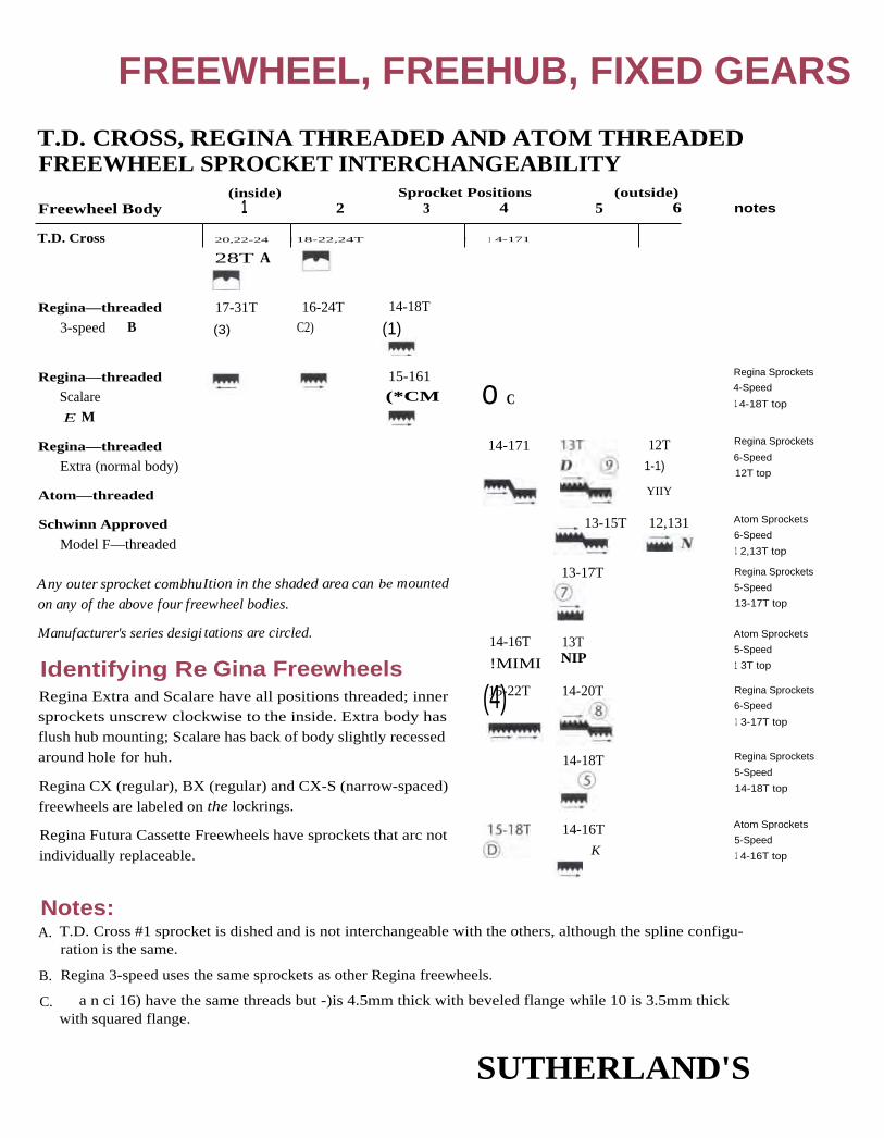
28T A
13-17T
13-15T
14-16T
K
14-20T
14-18T
12,131
15-161
(*CM
Any outer sprocket combhuItion in the shaded area can be mounted
on any of the above four freewheel bodies.
FREEWHEEL, FREEHUB, FIXED GEARS
T.D. CROSS, REGINA THREADED AND ATOM THREADEDFREEWHEEL SPROCKET INTERCHANGEABILITY
(inside) Sprocket Positions (outside)Freewheel Body 1 2 3 4 5 6
T.D. Cross 1 20,22-24 1 18-22,24T ! 1 4-171
notes
Regina—threaded
3-speed B17-31T 16-24T 14-18T
(3) C2) (1)
o C
14-171
15-22T(4)
14-16T
!MIMI
13TNIP
12T
1-1)
YIIY
Regina—threaded
Scalare
E M
Regina—threaded
Extra (normal body)
Atom—threaded
Schwinn Approved
Model F—threaded
Manufacturer's series desigi
Gina FreewheelsRegina Extra and Scalare have all positions threaded; inner
sprockets unscrew clockwise to the inside. Extra body hasflush hub mounting; Scalare has back of body slightly recessed
around hole for huh.
Regina CX (regular), BX (regular) and CX-S (narrow-spaced)
freewheels are labeled on the lockrings.
Regina Futura Cassette Freewheels have sprockets that arc not
individually replaceable.
Regina Sprockets
4-Speed
1 4-18T top
Regina Sprockets
6-Speed
12T top
Atom Sprockets
6-Speed
1 2,13T top
Regina Sprockets
5-Speed
13-17T top
Atom Sprockets
5-Speed
1 3T top
Regina Sprockets
6-Speed
1 3-17T top
Regina Sprockets
5-Speed
14-18T top
Atom Sprockets
5-Speed
1 4-16T top
tations are circled.
Identifying Re
Notes:A. T.D. Cross #1 sprocket is dished and is not interchangeable with the others, although the spline configu-
ration is the same.
B. Regina 3-speed uses the same sprockets as other Regina freewheels.
C. a n ci 16) have the same threads but -)is 4.5mm thick with beveled flange while 10 is 3.5mm thickwith squared flange.
SUTHERLAND'S

FREEWHEEL, FREEHUB, FIXED GEARS
T.D. CROSS , REGINA THREADED AND ATOM THREADEDFREEWHEEL SPROCKET INTERCHANGEABILITY (CONT'D )
Notes: (cont'd)D. New-style ® (threaded 1161*. as shown) is clearly not interchangeable with old-style ® threaded !.
Old-style ® is no longer available (see note M for its use on Scalare body).
E. Note that Regina Scalare is the only all-position threaded body that will accept a 15T sprocket in the
3rd position.
K. Regina ® and Atom ©sprockets here are interchangeable with Schwinn F2 and F3, and with Normandy
outer sprockets. (See page 4-34.)
M.Old-style Scalare freewheels do not use the Regina and Atom outer combinations shown, but have (1) in
place of (10) and old-style ® in place of ® making a 00 old(9)(7) five-speed instead of the current(3)(2)(10)(6)
N. Atom 12, 13T with 34.8mm O.D. thread also fits Regina CX-S and ;Millard Helicomatic 7-speed.
SUTHERLAND'S

Freewheel
ARIS7-speed narrowCC body H87-89 3 notch
6-speed regular 3 notchCS body H87-92
7-speed '903 notch H
7-speed '91, '924 notch H, I
8-speed Pre '924 notch
8-speed '924 notch
7-speed '924 notch
6-speed '924 notch
FREEWHEEL, FREEHUB, FIXED GEARS
SACHS, MAILLARD: ARIS FREEWHEEL SPROCKETI NTERCHANGEABILITY (SEE MAILLARD PAGE 4-26)
Notes:H. ARIS sprockets can be used in place of the corresponding Maillard 700 sprockets. Maillard 700 sprockets
cannot be used on ARIS freewheels if indexing is to be used.
I. Aris freewheel body with 4 notches but comes stock with 3 tab cogs. 4 tab cogs will work also.
1. 4 tab cogs will only work on 4 notch bodies
K.[*AY] cogs are the same as, (4 tabs, 1.8mm thick unlike [AY]
which is 3 tab and 2.0mm thick)
L.[*BY] cogs are the same as ., (4 tabs, 1.8mm thick unlike [BY], which is 3 tab and 2.0mm thick)
[AY], SY and *AY can be mixed on 4 tab bodies and will still index properly if the proper spacers are used( match cog to corresponding spacer on inner side).
RY , and [*BY] can be mixed the same as [AY], [SY] and
Sprockets should be placed so that the open end of the "Y" tooth profile points in the direction of travel,clockwise.
SUTHERLAND'S
BY

Freewheel
ARTS7-speed narrowCC body87-89 3 notch
6-speed regularCS body87-92
7-speed '90
7-speed '91, '92
8-speed Pre '92
8-speed '92
7-speed '92
6-speed '92
(inside) Sprocket Positions (outside)2 3 4 5 6 7 8
FREEWHEEL, FREEHUB, FIXED GEARS
ARIS SPROCKET SPACERS
* If the larger sprocket is larger than 18 teeth, use the [M] spacer.
** f the larger sprocket is larger than 18 teeth, use the [H] spacer.
FreewheelModel Body I Speeds & Spacing Spacer I. D. O.D. Thickness
ARIS CS 6-speed regular pre'92 3564 white (A) 50 56.5 3.45
3583 white (B) 44 53 3.45
— 6-speed regular after '92 grey (C) 50 56.5 3.65
grey (D) 44 53 3.65
grey (H) 44 56.5 beveled 3.65
CC 7-speed pre '89 3568 black (F) 50 56.5 2.95
— 7-speed '9Q'91,'92 3569 black (F) 50 56.5 2.95
8-speed pre '92 black (G) 44 53 3.0
7-, 8-speed after '92 brown (U) 50 56.5 3.2
brown (V) 44 53 3.2
black (M) 44 56.5 beveled 3.2
SUTHERLAND'S

Freewheel
Maillard 600 SHHelicomatic5-speed
Maillard 600 SHHelicomatic6-speed narrow
Maillard 700 SHHelicomatic7-speed narrowSHC body
Maillard 700 SHHelicomatic6-speed narrowSHC body
Atom 77 B5-sprocket body6-speed narrow
Atom 77 B6-sprocket body6-speed narrow
Maillard 700 Course6-speed regularMM body
Maillard 700 Course5-speed regularMM body
Sachs-Huret Orbit6-speed
Maillard 700 Compact6-speed narrowCC body
Maillard 700 Compact7-speed narrowCC body
(inside) Sprocket Positions1 2 3 4 5
(outside)6 7
FREEWHEEL, FREEHUB, FIXED GEARS
MAILLARD, ATOM 77, SACHS-HURETFREEWHEEL SPROCKET INTERCHANGEABILITY
SUTHERLAND'S

FREEWHEEL, FREEHUB, FIXED GEARS
MAILLARD, ATOM 77, SACHS-HURETFREEWHEEL SPROCKET INTERCHANGEABILITY (CONT'D)
Notes:A. Maillard 700 5th-position sprocket has a wide inner flange and may be used on a 600 SH 5-
speed directly; it is too wide for use on a SH 6-speed. 600 SH 6-speed outer sprockets Ref.
MHrequire Maillard spacer Ref. 2261 when used on aSH5-speed. Sonic Maillard 700s havea body S sprockets wide, with an outer sprocket pair and a 13T minimum. Others have a
body 6 sprockets wide, with all sprockets threaded on and a 14T minimum.
B. The Atom 77 freewheels listed here are narrow 6-speeds. All sprockets of 6-sprocket body
Atom 77 attach directly onto body. The 6th-position sprocket of 5-sprocket body Atom 77attaches to 5th-position sprocket. The 5-sprocket body Atom 77 can be built up as a 7-speed
using Maillard SHIT, SHE) and SHE sprockets in 5th, 6th and 7th position.
D. Sachs Orbit inner sprocket is dished and so not interchangeable with others.
E. 14, 15T Maillard 700 sprocket's inner flange is not high enough to secure neighboring
lugged sprocket on Orbit.
F. Also interchanges with 3-lug sprockets on Normandy; Schwinn Approved Models F2, F3 and
J; Shimano MF 1501, A-type and B-type. (See page 4-34.)
G. Sprockets are sold as a pair but can he separated.
H. ARIS sprockets can be used in place of the corresponding Maillard 700 sprockets. Maillard
700 sprockets cannot be used on ARIS freewheels if indexing is to be used. (See page 4-24.)
MAILLARD SPROCKET SPACERS
FreewheelModel Body Speeds Ea Spacing Spacer I.D. O.D. Thickness
Helicomatic SHC 6-, 7-speed narrow 2263 silver steel
or black plastic
45.5mm
45.5mm
50mm50mm
3.0mm3.0mm
700 Course MM 5-, 6-speed regular 2160 red2163 red
50mm44mm
56.5mm
54mm
3.6mm3.65mm
700 Compact CC 6-, 7-speed narrow 2141 green 50mm 56.5mm 3.0mm
SUTHERLAND'S

29 30 32 34
32
SprocketCombinations:
Sprockets listed togetherin black vertical boxesare interchangeable.
Groups of sprocketslisted together in redhorizontal boxes are onlyinterchangeable as agroup with the adjoininggroup.
32.
32 3030
29 34
SHIMANO HYPERGLIDE CASSETTE SPROCKET INTERCHANGEABILITY11
8-Speed XT andPQ
12 13 14 15
XTR12 141 2 1 3 141 2 1 4
16
161611 6
17 18 19 20 21
18 21
23 24 25 26 28
24 281818
2121
24 2824 28R 11
8-Speed: CS-7401 (Dura Ace), CS-HG90-8, CS-HG70-8ST
[12] 13 14 1515
19[16]1 6
1717 1 9
2121 23 . 13 14
UV
12 13 14 1515
1717
1919
21 2323 26, 1 13
[14 21
W 12-13
J 15 17 19 21 23 25
8-Speed Com actah '95 111 12 14 16 1 8 21 24 28ae 11 12 13 14 115 1 71 19 21,
7-Speed Compactab [11] 12 13 14 1 5 1 7 1 9ac 11 [ 13 15 18 21 24 28ai '95 11 12 14 16 18 21] 24
7-Speed StandardB'89 1 2 14 1 6 18 21 [24 28E 1 2 1 4 116 18] 21 24 __ 28F 1 4 116 [18] 21 [24] 28D '89 1 4 16 18 21 24 28C '89 13 15 17 20 23 26G 13 115 [17] 20 23 26K 13 15 17 ,20 24M 13 15 17 19 21 24 28H 13 15 17 [19 21 23 26L 1 2 13 14 15 17 19 21I 13 14 15 17 19 21 23
j 13 14 15 16 17 19 21
6-Speedad 12
[14] 16 18 21 24of '95 11 13 15 18 21 24
7-Speed IGag '95 11 1 3 15 18 21 24 28
Gray shading indicates sprockets are bolted to a spider.
Red shading indicates sprockets are riveted together.

FREEWHEEL, FREEHUB, FIXED GEARS
SHIMANO HYPERGLIDE SPACERS AND LOCKRINGS(inside) Sprocket Positions (outside)
Cassette 1 2 3 4 5 6 7 8
Hyperglide8-speed XTR
Group mark P
noneAA
none Hyperglidelockring BB5mm
8-speedGroup mark R
8-speed XTRGroup mark Q
8-speedGroup5, T, U, V, W
AluminumSilvermark 85
Hyperglide-C8-speed
Group mark ah
8-speedGroup mark ae
spacer B3.0mm
Hyperglide-Clockring BB5mm
7-speedGroup mark ab
7-speedGroup mark ai
Resin-dark greymark 7S
spacer B or D3.15mm
spacer8mm
Hyperglidelockring BB5mm
7-speedGroup mark ac
Hyperglide7-speed
Group mark L
7-speedGroup markF, G, H, I, J, K,
7-speedGroup mark E
7-speedGroup markB, C, D (1989)
6-speedGroup mark ad
Hyperglide-C6-speed
Group mark at
Interactive Glide7-speed
Group mark ag
spacer11E03001 mm
Hyperglide-Clockring BB5mm
spacer A\IT3.3mm
none
spacer Aor C Z
Hyperglidelockring X
3.3mm 7mm
spacer Hyperglide11E0300 Lockring BB1 m m. 5mm
Hyperglide-CRivetedunit
lockring BB5mm
Hyperglide-CRivetedunit
Lockring X5mm
(See page 4-30 for footnotes.)
SUTHERLAND'S

Number ofSprockets Joined LengthModel
5
5
5
not used not used
21.5
23.0
riveted
7-speed Hyperglide Group B, C, D 5 23.0
7-speed Hyperglide Group E, F, G, H, I, J, K, M
7-speed Hyperglide Group L
8-speed Hyperglide Group 5, T, U, V, W
7-speed Hyperglide-C Group ab
7-speed Hyperglide-C Group ac, ai
8-speed Hyperglide-C Group ae
8-speed Hyperglide-C Group ah
6 28.5
5
6 25.7
21.5
4 16.85
5 21.5
5 21
25.7
Dura-Ace
7-speed Non-Hyperglide
6-speed Non-Hyperglide
6-speed Hyperglide
FREEWHEEL, FREEHUB, FIXED GEARS
SHIMANO HYPERGLIDE SPACERS AND LOCKNUTS (CONT'D)
Notes:1989 Group mark vs. 1990 and later: 1989 group mark cassettes use 23mm through bolts thatscrew into the 5th sprocket from the inside. This requires a 3.3mm spacer (A) that has indents orholes to clear the ends of the bolts. The lockring is 7mm thick and requires a lockring spacer.
1990 and later 7-speed cassettes use 28.5mm through bolts that screw into the 6th sprocket fromthe inside. This requires a 3.3mm spacer (Hyperglide A) that has holes for the bolts. The lockringis 5mm thick and requires no spacer.
Hyperglide 8-speed cassettes use 26.5mm alien head through bolts that that screw into the 6thsprocket from the inside. This requires a sprocket with notches to clear the ends of the bolts.
X. 7mm thick lockring must be used with lockring spacer or lockring will hind on freehub.
Y. Hyperglide A spacer has holes for through bolts. If no through bolts are used, non-hyperglide3.3mm spacer may be used.
Z. Spacer C used on B, C, and L) groups has indentation for ends of through bolts.
AA. Spider provides spacing: XTR (groups P and Q) sprockets are bolted to spider. XT (group R)sprockets are riveted on.
BB. Hyperglide-C lockrings should be used on only 11-tooth cassettes; standard Hyperglidelockrings should only he used on cassettes with outer cogs greater than 11 teeth. TheHyperglide-C lockrings are 35.3mm in diameter. Standard Hyperglide lockrings are 37.9mmin diameter. Hyperglide-C lockrings will not adequately grip standard Hyperglide cassettes,and standard Hyperglide lockrings will interfere with the chain on 11-tooth cogs.
SPROCKET THRU BOLTS
SUTHERLAND'S

FREEWHEEL, FREEHUB, FIXED GEARS
SHIMANO FREEHUB (CASSETTE) SPACER DIMENSIONS
Speeds Spacer Thickness Color I. D. O.D.
8-speed spacer B 3.0mm Silver 34.5mm 42mm
7-speed spacer B
spacer A
3.1 mm*
3.3mm
Grey
Black
34.5mm
34.5mm
38.5mm
38.5mm
6-speed spacer B
spacer A3.65mm1.0mm
34.5mm34.5mm
42mm42mm
8-, 7-, or6-speed
washerwasher
1.0mm0.8mm
BlackBronze
34.5mm
34.5mm
38.5mm
38.5mm
• Resin Spacers are listed as 3.15mm, steel as 3.1 mm.
SHIMANO FREEHUB (CASSETTE) BODIES - LENGTHS
SpeedsFreehub BodySpline Lengths
OverlockoutDimensions
SHIMANO5-speed 23 120, 126
6-speed Hyperglide or non-Hyperglide 28.4 126, 130
7-speed Hyperglide or non-Hyperglide 30.4 126, 130, 135
8-speed Hyperglide or non-Hyperglide 34.8 130, 135
6-speed Hyperglide-C 25.6 130
7-speed Hyperglide-C 28.4 126, 130, 135
8-speed Hyperglide-C 32.9 130, 135
Hyperglide and non-Hyperglide splines run to the end of the cassette body.
Non-Hyperglide splines overlap the threaded section.
Hyperglide-C splines run to within 3mm from the end of the cassette body (2.5mm for 6-speedand 1.7mm for 7- or 8-speed) .
A spacer can he added to an 8-speed body to convert it to a 7-speed cassette.
SUTHERLAND'S

Marked:INDEX7S or 7-8S
C
14-26,28,30,32,34T E D
Marked: 65or no mark12-18T
No mark13-16T
FREEWHEEL, FREEHUB, FIXED GEARS
SHIMANO NON-HYPERGLIDE CASSETTE SPROCKETI NTERCHANGEABILITY
Cassette
Dura-Ace ACS-7400-8
8-speed
Dura-AceCS-7400-7
7-speed
Sante CS-5000600 UltegraCS-6400-7
7-speed
Dura-Ace ACS-7400-6
6-speed,5-speed B
600 EXCS-6400-6CS-6208-6Standard CS-1000
6-speed
(inside) Sprocket Positions (outside)1 2 3 4 5 6 7 8
Marked:INDEX7S or 7-8S12-14T
13-15Tw/ built-in spacer
Marked: 6S7S or 7-8512-16T
1 3TMarked:13 INDEX6S
D, Ew/ built-in spacer
N otes:A. Includes AX, EX and "New" Dura-Ace.
B. Dura-Ace AX and EX 5-speed has same outer 2 sprockets as 6-speed with one less inner sprocket.
C. Dura-Ace threaded-on cogs (champagne colored) are not interchangeable with others.
D. Cog without built-in spacer can be used here when combined with proper spacer.
E. To mount as a cassette, sprockets used in sprocket position 5 on a 6-speed or 7-speed must have threadedsprocket through-bolt holes.
F. Standard spline sprockets are interchangeable with Dura-Ace and others, but do not have the high-perfor-mance tooth profile.
SUTHERLAND'S

FREEWHEEL, FREEHUB, FIXED GEARS
SHIMANO NON-HYPERGLIDE CASSETTESPROCKET SPACERS
(inside) Sprocket Positions (outside)Cassette
Dura-Ace ACS-7400-8
8-speed
Dura-AceCS-7400-7
7-speed
Sante C5-5000600 UltegraCS-6400-7
7-speed
Dura-Ace ACS-7400-6
6-speed, 5-speed
600 EXCS-6400-6CS-6208-6Standard CS-1000
6-speed
1 2 3 4 5 6 7 8
Aluminum none noneSilverSpacer B3.0mm
Steel- none noneSilverSpacer B3.1 mm J
Resin- Resin- noneDark Grey
I mark: 75Dark Greymark: 75
Spacer B 2nd position3.1 5mm Spacer A
3.3mm H
Steel-Grey none noneSpacer B3.65mm K
Resin-Light Resin- Steel withGrey Light spline cutsSpacer B Grey3.7mm Spacer B H
3.7mm H
Notes:A. includes AX, EX and "New" Dura-Ace.
H. None if sprocket has built-in washer.
I. Steel-Silver 75 Spacer B may be used in place of Resin-Dark Grey 75 Spacer B if sprocket through -bolts
are not used.
K. Steel-Grey 65 Spacer B may be used in place of Resin-Light Grey Spacer B if sprocket through-bolts are
not used.
SUTHERLAND'S

NormandySchwinn ApprovedModel F2, F3
Shimano MF-1501,Schwinn ApprovedModel J
Shimano UniglideMF-1500, MF-15105-speed G
Shimano UniglideMF-16006-speed G
Shimano A-typeModel FC-300 /
Shimano B-typeModel FC-300
Shimano 600 MF-6140MF-6151, 62075-speed
Shimano Dura-Ace (old)MF-71505-speed
Shimano 600 MF-6160MF-6161, 62076-speed
Shimano Dura-Ace (old)MF-71606-speed
17-24, 26, 28, 30, 32, 34T16-26, 28, 30, 32, 34T16-26, 28T
C
16-26, 28T16-26, 28T
FREEWHEEL, FREEHUB, FIXED GEARS
SHIMANO, NORMANDY AND SCHWINN APPROVED (MODELS F2,
F3 AND J) FREEWHEEL SPROCKET INTERCHANGEABILITY(inside) Sprocket Positions (outside)
Freewheel 1 2 3 4 5 6 7
SUTHERLAND'S

Freewheel(inside)
1 2
ShimanoUniglide600UGDura-Ace6-speed
MF-Z012MF-6208MF-7400
[A]
ShimanoUniglide5-speed
MF-Z012 [A]
ShimanoDura-AceSante7-speed
MF-7400MF-5000
[7A]
Sprocket Positions (outside)3 4 5 6 7
none
A noneX
7A 17B ]X
[7C]
Xnone none
FREEWHEEL, FREEHUB, FIXED GEARS
Notes:A. Sprockets above the dotted line are 3-dog type; sprockets below the dotted line are sawtooth-
splined type except 30, 32 and 34T. 3-dog sprockets will fit on sawtooth splines of cassettebodies in positions 1, 2,and 3, but sawtooth-splined sprockets will not fit 3-dog bodies.
C. Sprockets with built-in spacers are marked 6S for 6-speed and 7S for 7-speed.
F. Also interchanges with Atom 77. (See page 4-26.)
G. Shimano Uniglide freewheel body lockring is level with outer rim. Splined sprockets are thin-
ner and will not lock in place if used on other similar Shimano freewheels.
H. Shimano Uniglide outer sprockets may be used on other similar Shimano freewheels if a spacer like
the one behind the 4th sprocket is used to the inside of each sprocket. The 16T sprocket requires aspecial beveled spacer (a bevel may be ground on the standard spacer) to prevent chain interference.
I. Note that Shimano A-type FC-300 has two threaded diameters and one splined diameter.
I. Note that Shimano B-type has outer sprocket threaded into face of body.
K. Schwinn Approved models F2 and F3 outer sprocket has special threads to accept high gear
chain guard; it is otherwise interchangeable with the Regina • and the Atom ®.
SHIMANO FREEWHEEL SPROCKET SPACERS
X. Use this spacer it not built in to next smaller cog.
SPACER DIMENSIONS
Spacer j D OD Thickness
A 49.5mm 53mm 3.65mmB 42.5mm 53mm 3.65mm beveledC 42.5mm 47.48mm 3.65mm
7A 49.5mm 53.5mm 3.1mm7B 43mm 53.5mm 3.1mm7C 43mm 47-48mm 3.1mm
SUTHERLAND'S

Superbe Pro8-speed
Microllte/SL7-speed
XC Pro, XC Comp,XC LTD, XCSport,XC Expert, XCD
7-speed
XCD 60006-speed
XC Comp ProMicrodrive
7-speed
XC Pro Microdrive8-speed
PowerFlo Rear PFR*FW-PF1 27-speed
PowerFlo Rear PFR*FW-PF1 26-speed
FREEWHEEL, FREEHUB, FIXED GEARS
SUNTOUR CASSETTE SPROCKETS(inside) Sprocket Positions (outside)
Cassette 1 2 3 4 5 6 7 8
Notes:Accushilt Plus and Accushift Plus II (also known as PowerFlo, though most commonly labeled
APID cogs can be used interchangeably, but shifting may vary when mixing the two due to dif-ferences in cog spline orientation.
The thru holt should be removed for t he SL hub.
SUNTOUR POWERFLO REAR FREEWHEEL SPROCKETI NTERCHANGEABILITY
(inside) Sprocket Positions (outside)Freewheel 1 2 3 4 5 6 7
* Also referred to as Accushift Plus III or PowerFlo 3.0. Do not confuse with "normal" PowerFlo.PowerFlo is spaced for Suntour derailleurs. PowerFlo rear is spaced for Shimano derailleurs.
(See page 8-3 for markings on PowerFlo cassettes and freewheels.)
SUTHERLAND'S
lockring

none none3.0mm2.8mmXC Comp, ProMicrodrive
7-speed
3.0mm none noneXC Pro Microdrive8-speed
8-speed Standard none none
3.3mm=
none
none3.0mm7-speed Standard
Grey 3.55mm6-speed
SpeedsFreehub BodySpline Lengths
OverlocknutDimensions
SUNTOUR6-speed 23.7 126, 130
7-speed 26.1 126, 130, 135
8-speed 30.8 130, 135
7-speed microdrive 20.7 130, 135
8-speed microdrive 25.4 135overlocknut dimension
FREEWHEEL, FREEHUB, FIXED GEARS
SUNTOUR CASSETTE SPACERS(inside) Sprocket Positions (outside)
Cassette 1 2 3 4 5 6 7 8
Notes:* Some claim this works.
Arrows on spacer point to the hole the pin goes through. Arrows on cogs point in the direction of
rotation (clockwise).
SUNTOUR POWERFLO REAR FREEWHEEL SPACERS(inside) Sprocket Positions (outside)
Freewheel 1 2 3 4 5 6 7
PowerFlo Rear PFR* 3.15 3.15 3.00mmFW-PF12 52mm 44mm 44mm none7-speed Blue Blue Black
* Also referred to as Accushifi Plus III or PowerFlo 3.0. 1)o not confuse with "normal" PowerFlo.
PowerFlo is spaced for Suntour derailleurs. PowerFlo rear is spaced for Shimano derailleurs.
SUNTOUR FREEHUB (CASSETTE) BODIES — LENGTHS
SUTHERLAND'S

18-26, 28,30, 32, 34T
[A]
i v 16Twithbuilt-inspacer
19-26, 28,30, 32, 34T
18-26, 28,30, 32, 34T
[B] 15-22T
15-22T
15-23T [B]15-22T[C] 15-17T10114TB
17-24T 16-24T
15-23T
17T I 16-23T 15-22T
LS]
13-15T
[C] 15-17T14T ,
13-16T
13-16T
[C] 15-171F 114T
13-16T
[L]
A 13-15T
14-16T
[x]
13-15T
E
15-24T
[C] 15-17T[H] 14T
12-14T
[U ]
13T
I I
15-23T [C] 15-17T[Pi 14T
FREEWHEEL, FREEHUB, FIXED GEARS
SUNTOUR ACCUSHIFT FREEWHEEL SPROCKETI NTERCHANGEABILITYWinner and WinnerPro 7-, 6-, and 5-speed freewheels are built on the same body.
a 7-, 6-, and 5-speed bodies are all different. 7-speed bodies have the threaded portion protrude 4.2mm from
freewheel face. 6-speed bodies have the threaded portion protrude 2mm. 5-speed bodies have a flush face.
Sprockets are stamped with the sprocket letter and number of teeth. The stamped side should be facing thenext largest sprocket.
Note: In SunTour literature, sprocket positions are numbered from 1 on the outside.
(inside)Freewheel 1
Sprocket Positions (outside)2 3 4 5 6 7
Winner FW-WT10-57UWinner WT-7000WinnerPro WP-7000
7-speed Ultra (narrow)
Winner FW-WT10-S6UWinner WT-6500WinnerPro WP-6500
6-speed Ultra (narrow)
Winner FVV-VVT10-S6RWinner WT-6000WinnerPro WP-6000
6-speed regular
Winner FW-VVT10-S5RWinner WT-5000WinnerPro WP-5000
5-speed regular
a FW-ALOO-S7Ua FW-ALOO-K7U
7-speed Ultra (narrow)
a FVV-ALOO-SR66-speed regular
a. F W-ALOO-SR55-speed regular
PowerFlo6-speed Ultra FW-PF00(5mm spacing)
PowerFlo7-speed Ultra FW-PF00
FW-P102
18-26, 28,30, 32, 34T
SUTHERLAND'S

FREEWHEEL, FREEHUB, FIXED GEARS
SUNTOUR ACCUSHIFT FREEWHEEL SPROCKETI NTERCHANGEABILITY (CONT'D)
Notes:A. If next smaller sprocket has more than 13T, then [B] sprockets can be used in this position.
B. If next smaller sprocket is 13T, use C or [D] . sprocket in this position.
If next smaller sprocket is [E] 14T or F E 15T, use [B] sprocket in this position.
SUTHERLAND'S

FREEWHEEL, FREEHUB, FIXED GEARS
SUNTOUR ACCUSHIFT FREEWHEEL SPACERS(inside) Sprocket Positions (outside)
Freewheel 1 2 3 4 5 6 7
Winner FW-VVT10-S7UWinner W1-7000 [UBD] UCB]
[
UCF] [ U[C]F M none noneWinnerPro WP-7000
7-speed Ultra (narrow)
Winner FW-VV1-10-56UWinner WT-6500 UBD [UCB]
[UCF] U[C]F M noneWinnerPro WP-6500
6-speed Ultra (narrow)
Winner FW-VVT10-56RWinner WT-6000 I BD [CB] [CB]
[SB] noneWinnerPro WP-60‘0
6-speed regular '
Winner FW-WT10-S5RWinner WT-5000 0 CB [C]BI R SB PWinnerPro WP-5000 RB
5-speed regular
a FW-ALOO-S7U 54mm ODa FW-ALOO-K7U UBD 44mm ID UCF] [ U[C]F [UCF] N none
7-speed Ultra (narrow) 2.8mmthick
a FW-AL00-SR6 BD] 54mm OD 54mm OD 48mm OD none6-speed regular 44mm 1D 44mm ID 44mm ID 44mm ID
3.6mm 3.6mm 3.6mm 3.6mmthick thick S thick R
/thick R
cx FW-AL00-5R5 [ BD] 0 54mm OD 48mm OD /none /
5-speed regular 44mm ID 44mm ID 44mm ID3.6mmthick
3.6mmthick R
3.6mmthick R
\PowerFlo FW-PF00 \
6-speed
PowerFlo FW-PF00 UBD] [UCB] 54mm OD U[C]F none7-speed 44mm ID
3.1mm 3.1 mm
PowerFlo FVV-PF02 52 ID 3.0mm 54mm OD none7-speed 3.0mm li ke UCB 44mm ID 3.0mm
SUTHERLAND'S

FREEWHEEL, FREEHUB, FIXED GEARS
SUNTOUR ACCUSHIFT FREEWHEEL SPACERS (CONT'D)
N otes: (cont'd)M. No spacer needed if [F] 14T is next smaller sprocket.
N. No spacer needed if [H] 14T is next smaller sprocket.
0. No spacer needed if V 16T is next smaller sprocket.
P. Spacer [SB] is used if next larger sprocket is a Hi sprocket. Spacer
sprocket is a [C] or D sprocket.
R. No spacer needed if 14T is next smaller sprocket.
S. Use [CBI if next smaller sprocket is 15T.
RBI is used if the next larger
SUTHERLAND'S

SD, Perfect - 1/8" chain3-speed
SD, Perfect - 1/8" chain4-speed
Pro-Compe PC-5000,Perfect PT-5000, AG
5-speed
Perfect PN-6000 B6-speed regular
(for use on Fujis and others)
Pro-Compe PC-60006-speed regular
Perfect PS-6000, PS656-speed regular
Perfect PS-65006-speed Ultra (narrow)
New Winner NW-7000,Microlite LF-7000 X
7-speed Ultra (narrow)
New Winner NW-6500,Microlite LF-6000 X
6-speed Ultra (narrow)
New Winner NW-60006-speed regular
New Winner NW-50005-speed regular
Winner-S6-speed regular
Winner-S5-speed
Note: In SunTour literature,
sprocket positions are num-
bered from 1 on the outside.
FREEWHEEL, FREEHUB, FIXED GEARS
SUNTOUR SPROCKET INTERCHANGEABILITY
Freewheel(inside) Sprocket Positions (outside)1 2 3 4 5 6 7
SUTHERLAND'S

FREEWHEEL, FREEHUB, FIXED GEARS
SUNTOUR SPROCKET INTERCHANGEABILITY (COrm))Notes:A. Interchangeable with Shimano Dura-Ace and 600 outer sprockets.
B. For use on Fuji and other bicycles with 124mm overlocknut hubs. Since this freewheel isslightly narrower, it may not work with some brands of standard chain.
C. Mounting 5-speed sprocket here leaves outer ball race exposed.
D. When moving a sprocket to the right across the dashed line, a bevel must be ground on theright side of the teeth. Sprockets moved to the left will fit regular width Winner, but must
have a high flange at the inside to secure Ultra Winner's splined sprockets.
E. Some sprockets have haf-circle shaped dogs and must he filed to fit freewheels below the
dashed line.
F. 1ST steel sprocket requires beveled spacer #15004514.
G. Ultra 16T and 14T sprockets have a narrow built-in spacer and fit only Ultra, New Winner
and Microlite bodies.
X. Letters in boxes are SunTour's series designations. Boxes where the first of at least two lettersis an A designate a Microlite sprocket or a spacer. Microlite aluminum sprockets are inter-
changeable with the New Winner steel sprockets, except splined AA sprockets that have eight
dogs and do not fit onto the steel body for sprockets with four dogs.
SUTHERLAND'S

FREEWHEEL, FREEHUB, FIXED GEARS
SUNTOUR SPACERS(inside) Sprocket Positions (outside)
Freewheel 1 2 3 4 5 6 7
SD, Perfect3-speed
SD, Perfect4-speed
Pro-Compe PC-5000,Perfect PT-5000, AG
5-speed
Perfect PN-60006-speed regular(for use on Fujis and others)
Spacer thicknessgiven in millimeterswith symbol.
SUTHERLAND'S

FREEWHEEL, FREEHUB, FIXED GEARS
SUNTOUR SPACERS (CONT'D)
Notes:F. 15T steel sprocket requires beveled spacer #15004514.
G. Ultra 16T and 14T sprockets have a narrow built-in spacer and fit only Ultra, New Winnerand Microlite bodies.
H. 15T sprocket requires beveled spacer #15004511 or #15004515.
I. Where thin shims are used in addition to standard spacers, they must be replaced exactly asthey were.
Y. [AUTF] spacer is for use only with Microlite sprockets.
SUTHERLAND'S
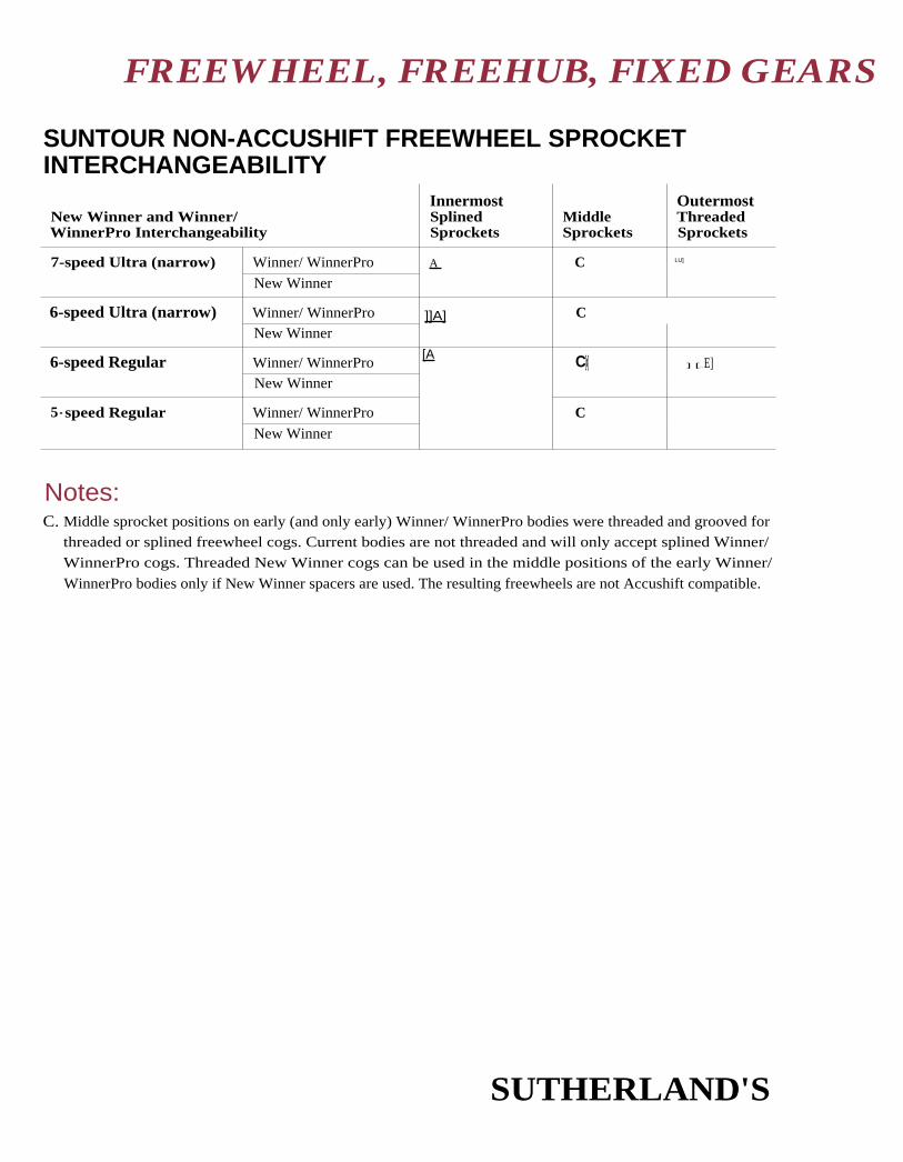
FREEWHEEL, FREEHUB, FIXED GEARS
SUNTOUR NON-ACCUSHIFT FREEWHEEL SPROCKETINTERCHANGEABILITY
New Winner and Winner/WinnerPro Interchangeability
InnermostSplinedSprockets
MiddleSprockets
OutermostThreadedSprockets
7-speed Ultra (narrow) Winner/ WinnerPro A C LU]
New Winner
6-speed Ultra (narrow) Winner/ WinnerPro ]]A] CNew Winner
6-speed Regular Winner/ WinnerPro[A C[x] ] [ E]
New Winner
5 - speed Regular Winner/ WinnerPro CNew Winner
Notes:C. Middle sprocket positions on early (and only early) Winner/ WinnerPro bodies were threaded and grooved for
threaded or splined freewheel cogs. Current bodies are not threaded and will only accept splined Winner/WinnerPro cogs. Threaded New Winner cogs can be used in the middle positions of the early Winner/
WinnerPro bodies only if New Winner spacers are used. The resulting freewheels are not Accushift compatible.
SUTHERLAND'S

Freewheel
Cyclo3-speed1/8" chain
Cyclo4-speed
1 2 3 4 5 6
15-28, 30T
14T Anot
removable
7
1 4T Anot
removable
Cycle 64, 72Com petition5-speed
Cyclo 64, 72Competition 13T top5-speed
Cyclo 64Competition6-speed
Cyclo Pans5-speed
Cyclo Pans6-speed
Cyclo Pans6-speed narrow
Cyclo Pans7-speed narrow
Cyclo, Type B(made in England) C
13T
1 4T Anot
removable
14-16TM68
14-16T
14T Anot
removable
16-20T
14-16T
1 4T Anot
removable
15-28, 30T
FREEWHEEL, FREEHUB, FIXED GEARS
CYCLO FREEWHEEL SPROCKET INTERCHANGEABILITY(inside) Sprocket Positions (outside)
Notes:A. This sprocket is part of the freewheel body and is not removable. Inner sprockets are left-
threaded and unscrew towards the inside.
B. For correct spacing on 6-speed, turn outside sprocket over.
C. Type B Cyclo is made in England and is unrelated to the French Cyclo models listed above it.All sprockets unscrew to the outside. To remove #5, loosen the others, lock #2 and #3 together(like cone and locknut) and loosen #5.
SUTHERLAND'S

(inside) Sprocket Positions (outside)1 2 3 4 5 6
17-26,28,30T 15-21T 14-18T
FREEWHEEL, FREEHUB, FIXED GEARS
G.CAIMI, EVEREST AND SIMPLEXFREEWHEEL SPROCKET INTERCHANGEABILITY
Freewheel
5-speedG. CaimiEverestSi mplex
6-speedG. CaimiEverestSi mplex
SUTHERLAND'S

Make of Freewheel Class of Fit — Tool
A Var 412Var 413 for French Juvenile
A DR.SD
A Campagnolo #1
A Var 187 LindenB Eldi
Regina
ReginaCampagnolo #1 (may need a bit of grinding)Eldi
Shimano Single and Freehub A removal toolKingsbridge 120SunTour EZ OFF 4 dog tool
SunTour Single freewheel removal toolKingsbridge 120SunTour EZ OFF 4 dog tool
EldiRegina
AB
AA
A
A
Atom-Maillard
Cyclo (French)103 fit 303
Everest
Merveille
Regina
Shimano - standardDX - 4-notch
SunTour (standard)
EZ OFF - 4-notch
TDC
FREEWHEEL, FREEHUB, FIXED GEARS
SINGLE-SPEED FREEWHEEL THREADSMost single-speed freewheels use the same threads as multi-speed freewheels, (see page 4-2).
Exceptions are as follows.
French Juvenile 32mm x 1.0mmSunTour mini size 30mm x 1.0mm
Tools For Removing Single-speed Freewheels
FIXED GEAR—HUB SHELLFixed gear hubs have a left-threaded lockring to secure sprocket. Thread sizes of fixed gear
sprockets are the same as those used for freewheels.
Thread sizes of lockrings may vary from maker to maker. A maker will usually use one lockring size
for all hubs, even though the sprocket thread is different. This is true of Campagnolo and Zeus.
Sprocket Lockring ThreadsCampagnolo 1.32" x 24 TPI left-threaded
English 1.29" x 24 TPI left-threaded
French 33mm x 1.0mm left-threaded
SUTHERLAND'S

FREEWHEEL, FREEHUB, FIXED GEARS
SUTHERLAND'S

CONTENTS
S
ShiftingChecklist ....................................... 2
Adjustment .................................. 3
About index shifting .................. 4
Problems ................................. 4
Brazed-on lever bosses
Thread sizes ................................ 5
Dimensions ............................. 5
Markings ................................. 5
Cable, casing, caps .................... 6
Casing caps illustrations ............. 7
Freewheel drop-out spacing ..... 8
Chain recommendations ............8
Troubleshooting chartBrazed-on lever bosses ........... 9
All lever mountings ............... 1 0
Derailleur............................... 1 1
Other symptoms ............ 1 2-1 4
SUTHERLAND'S

INDEXING DERAILLEURSItems to
check first I NDEXING CHECKLIST Page numbers to findmore information
COMPONENT COMPATIBILITYCampag -
nolo Sachs Shimano SunTour
Levers compatible with derailleurs. 6-4 6-9 7-3 8-3Levers compatible with freewheel spacing 6-4 6-9 7-3 8-3Derailleur compatible with freewheel minimum andmaximum teeth with given rear drop-out.
6-5 6-9 7-6 8-6
Chain compatible with derailleur and freewheel. 6-2 6-8 7-2 8-2Correct space for freewheel plus drop-out thickness. 5-8, 5-8 5-8 5-8Brazed-on lever bosses must be correct dimensions. 5-5 5-5 5-5 5-5
For large diameter down tubes (larger than28.6mm) use flat lever stop instead of radiused one.
CABLE AND CASING
Cable is correct diameter and smooth to touch. 5-6 5-6 5-6 I 5-6Cable casing seated, "stretched/' and lubricated.
Casing is compatible. 5-6 5-6 5-6 5-6Casing ends cleanly cut, capped using correct caps. 5-7 . 5-7 5-7 _ 5-7
Cable routing is smooth with no kinks or sharpbends. Route is not inside frame.
Cable casing is correct length to eliminate binding atcable stops and derailleur.
Cable stops are tight on frame.
Cable is on correct side of derailleur anchor bolt.
Cable anchor bolt is tight.
LEVERS
Lever clamp is tight.
Selection ring set for desired function.
Lever not too tight or too loose.
Check lever for wear causing too much free play.
Campagnolo lever insert correct.
DERAILLEUR
Derailleur is mounted securely to drop-out.
Check derailleur and guide pulley for wear.
6-3 L8-3 I
6-4 1
Guide and tension pulleys not reversed. 5-14 5-141
CHAIN
Check chain for wear.
SunTour Pro, Regina CS-X or Regina 50 5-14 5-14Anniversario chain right side up.
FREEWHEEL
Check cogs for wear.
Check bearings for wear and looseness.
Freewheel cogs installed correctly front to back on 4-15 4-24 4-20 4-26body and correct spacers used in assembly. 4-22
FRAME
Drop-out parallel. 0-10 0-10 0-10 0-10Gear hanger adjusted. 5-3 5-3 5-3 5-3
Correctly Spec'd
SUTHERLAND'S

INDEXING DERAILLEURS
I NDEXING ADJUSTMENT(See page 6-3 for additional Campagnolo setup tips.)
Frame 1. Align the drop-outs with a fork end gauge set.Adjustments
2. Align the gear hanger with gear hanger adjustment tool.
Derailleur 3. Attach derailleur to hanger.Adjustments
4. Set shift lever to friction mode, if possible.
5. Adjust high gear and low gear adjusting screws. Adjust the guide
pulley so it is centered under the smallest cog with the high gear adjust-ing screw. Then adjust the guide pulley so it is centered under the largest
cog with the low gear adjusting screw.
6. Check chain length. Put chain on largest chainring and smallest freewheelcog. Guide pulley and tension pulley centerline should be close to rightangles to the ground. Check the large chainring and large freewheel combi-
nation to be sure there is enough chain. Check the small chainring andsmall cog combination to be sure the derailleur can handle the chain length.
7. Stress the cable. Be sure the casing ends are seated and the cable end is
seated in the lever.
8. Check cable smoothness. A slight movement of the lever should move
the derailleur a slight amount. (See Cable and Cable Casing, page 5-6.)
9. Adjust derailleur angle for guide pulley clearance. Some derailleursdon't have this adjustment screw. Some SunTour derailleurs rely on the D/T
attachment. (See SunTour Derailleur Capacity Chart, Chapter 8.)Unscrew the angle adjusting screw until it doesn't affect the angle of the
derailleur. While on the smallest chainring, shift to the largest cog andthen shift down one cog. If it hesitates in down-shfting, turn the angle
adjusting screw in until the chain shifts off the largest cog. The guide
pulley should he as close as possible to the sprocket without makingexcess noise when back pedaling.
10. Set shift lever to indexing mode, if this is not already done.
11. Adjust cable tension. Shift to the second smallest cog. Tighten the
cable with the adjusting barrel until it is slightly too tight. Then turn the
crank and loosen the cable until the symptoms are eliminated. Continuethrough all (he cogs making adjustments as needed.
12. Shift through all the gears. Run through all the gear combinations with
the smallest and largest chainrings and readjust as needed. (See IndexingChecklist on page 5-2 and Indexing Troubleshooting Chart onpages 5-9 through 5-14 as needed.)
SUTHERLAND'S

INDEXING DERAILLEURS
ABOUT INDEX SHIFTINGIndex shifting requires more attention to details when adjusting and repairing than non-index
shifting. A chattering rear derailleur in a non-indexing system is taken care of by moving the leverslightly. In an i ndexing system that same symptom may need to be fixed using a repair stand.
There are about ten different components that determine how well an indexing system works.
In each one of these components there is a little play, a little room for wear, and an allowancefor slight misadjustment. This play, wear, and misadjustment allowance can add up and keepthe system from working. Hopefully, the system is designed so that a little play here is canceledout by a little wear there, and the system works well for a lot of miles.
Indexing systems are designed as a whole, with levers, cable, cable casing, cable casing end caps,derailleurs, drop-outs, derailleur hangers, hubs, freewheels, and chain all matched carefully to
produce a complete system. Interchangeability is not practical between systems. Our mea-surements of various systems indicate you cannot mix manufacturers' components. WithinSunTour there is a lot of interchangeability and within Shimano there is a lot (see tables forexceptions), but between the two t here isn't any consistent interchangeability.
In an ideal index system, the derailleur guide pulley is close to centered under each freewheelcog when each shift is completed. Up-shifting arid checking each cog, then down-shifting andchecking each cog is 12, 14, 18 or more checks. Some less than ideal combinations of compo-nents will shift in the repair stand and maybe work for a couple of weeks of riding, but then benothing but trouble after wearing in a little. Thoroughly checking systems, although time con-suming, is the only way to spot potential problems.
The information in this section is derived largely from manufacturers' information and ourexperience. There are a lot of factors that are common to all systems and some that are uniqueto each brand. This section is divided up to reflect that.
ProblemsAssuming the components are compatible, cable and cable casing are the components to checkfirst. (See the checklist on page 5-2 for a detailed list of cable and cable casing-relateditems to check.)
Next, check the chain for wear and compatibility. Many times, a change of chain can remedy theproblem. (See chain page and each manufacturer's page for chain recommendations.)
Systematically going through the checklist on the previous page should nail down any problems.(If it doesn't, go to the troubleshooting section which begins on page 5-9.)
SUTHERLAND'S

A: 9mm
B: 5.85mm
C: 4.5mm
D: 5mm
E: 12mm
INDEXING DERAILLEURS
BRAZED-ON SHIFT LEVER BOSSES
Thread SizesCampagnolo 5mm x 32 TPl*Sachs-Huret 5mm x 0.8mm*SunTour 5mm x 0.8mm*Shimano 4.5mm x 0.75mm
* 5mm x 32 TPI and 5mm x 0.8mm are so close, they are interchangeable.
MarkingsShimano lever fixing bolts with 5mm x 0.8mm threads are marked M5. Shimano lever fixingbolts with 4.5mm x 0.75 threads are unmarked.
Campagnolo Type Boss (sometimes referred to as Italian)
Shimano A Type Boss
Shimano levers designed for Cam pagnolo type bosses can
be mounted to Shimano A Type bosses using Shimano
Conversion Kit (680 9858) for M4.5 lever boss.
OShimano B Type Boss
SUTHERLAND'S

INDEXING DERAILLEURS
CABLE, CABLE CASING, AND CASING CAPSCable, cable casing, and casing caps are a critical part of successful index systems. Keep in mind
the following:
Cable• Use a high quality 1.2mm cable that is smooth to the touch. The exceptions are Shimano
Dura-Ace systems, which use 1.5mm braided cables. SIS '95 XTR, Xi 1.1mm contoured
outer strand cables can be used in place of I.2mm cables. It is best to measure cables sincethe finish can make the cable appear fatter or thinner.
• SunTour recommends using 1.2mm cable for all its indexing systems.
• Using larger or smaller diameter cable changes the amount of derailleur movement and isnot recommended. (Thick Campagnolo derailleur cables change the amount of derailleur
movement and should be avoided.)
• Using a 1.1mm cable on twist-shift style levers is common.
Cable Casing• Use Shimano SIS or SunTour Accushift casing. (Accushift casing is better than casing marked
SunTour Index.)
• Do not use ordinary wound or lined cable casing.
• Casing ends must be cleanly cut and/or ground smooth with a grinder or file.Shimano cable cutter TL-CT1O is recommended.
• Cable casing must be correct length to eliminate binding at stops and derailleur.Casing should curve without abrupt or compound bends.
• Internal routing of cables is not recommended; it causes too many tight bends. Some bikesbenefit from switching routing to upper cable stops, and then crossing cables under downtube, making sure they don't rub frame.
Casing Caps• Use casing caps on casing ends. Be sure casing caps closely fit the casing, the derailleur,
and the cable casing stops on the frame. Shimano and SunTour make several different
casing caps. (See next page.)
SUTHERLAND'S

INDEXING DERAILLEURS
CABLE CASING CAPSCable Casing Casing Caps Casing Stop
SUTHERLAND'S

Chain with Bushing Chain without Bushing
INDEXING DERAILLEURS
CASSETTE/FREEWHEEL DROP-OUT SPACINGThis chart is based on a normal drop-out thick-ness Dimension C of 6.5mm. Dimension B isthe handiest since it can he measured with thewheel and the cassette or freewheel mountedin the bicycle.
Shimano recommends that the drop-out he7,5mm plus or minus 0.5mm thick. Drop-outsare often closer to 6.5 mm.
For wheels with freewheels, when Dimension
B is too great, add a spacer between the free-
wheel and the hub. Be sure to check the clear-ance between the frame and the chain when
the chain is on the smallest cog.
Extra thick drop-outs on aluminum framesmay cause Dimension B to go over the rec-
ommended amount. This can cause difficultyshifting the largest cogs as the derailleurswings to its inside limits.
Freewheel A B
Campagnolo 7-speed narrow spaced 36.0 9.5 - 11.56-speed regular spaced 36.0 9.5 - 11.5
Shimano 8-speed spaced 40.5 10.0 - 11.57-speed narrow spaced 36.0 - 38.0 1 0.5 - 11.56-speed regular spaced 34.5 - 37.0 11.5 - 15.0
SunTour 7-speed narrow spaced 36.5 11.5 - 13.56-speed regular spaced 36.5 11.5 - 13.55-speed regular spaced 36.5 12.5 - 15.5
CHAIN RECOMMENDATIONSBushingless chain has the ability to twist more than chain with bushings. Some systems workbest with a chain that will twist and some with a chain that resists twist. Be sure to follow the
recommendations in each manufacturer's section.
SUTHERLAND'S

INDEXING DERAILLEURS
TROUBLESHOOTING CHART
Shift Lever: Brazed-on BossesTrouble Cause Remedy
Lever doesn't fitor is too loose.
Brazed-on bossdimensions incorrect.
Carefully remove paint and chrome.
Check dimensions of boss. Oversize dimensionscan be carefully filed down. Undersize boss maybe unusable.
Lever movement istoo tight or selectoris difficult to turn.
Lever friction adjustingscrew is too tight.
Lever boss is too largefor lever.
Loosen lever friction adjusting screw slightly.
Check lever boss flat dimensions, (see page 5-5,measurement E).
Boss hole not centered. Replace boss.
Lever friction adjustingscrew won't tightenenough.
Lever boss threadingis not deep enough.
Grind a small amount off the end of the frictionscrew. Note: Grind as little as possible.
Braze or glue in leverboss threading.
Clean threads using correct tap.(See lever boss dimensions, page 5-5.)
Spacer or washermissing.
Check assembly against exploded drawing
in catalog.
Boss is too long. Carefully grind a little off the end of the boss.
Flats are not deep
enough.
Carefully file the flats deeper.
Index selectordoesn't work.
Lever boss flatsperpendicular todown tube.
Replace boss.
SunTour: If flats are installed exactly 90' to downtube, the lever will shift ultra freewheels whenindicating "RE," and will shift regular spaced free-
wheels when on "UL." Some SunTour clampmount lever flats are 90" to the down tube. Thelevers attached to these clamps can be used whenthe lever bosses are perpendicular to the down
tube. GPX levers don't engage the flats and canbe used.
SunTour: Using clampmount levers on
brazed-on bosses.
See above note.
Replace radiused lever stop with flat lever stop.Lever stop does not fitdown tube.
Down tube diameter isgreater than 28.6mm.
SUTHERLAND'S

INDEXING DERAILLEURS
TROUBLESHOOTING CHART (CONTD)
Shifter: All MountingsTrouble Cause ' Remedy
Index selector Mode selector is set Check that the mode selector is lined up
doesn't work. between functions. correctly with desired function.
Shifter movement is Shifter friction adjusting Loosen lever friction adjusting screw slightly.
too tight or selector
is difficult to turn.
screw is too tight.
Shifter doesn't index Shifter not designed for Check shifter compatibility chart
with 8-speed freewheel. 8-speed freewheel. for correct shifter
Shifter doesn't index Shifter not designed for Check shifter compatibility chart
with 7-speed freewheel. 7-speed freewheels. for correct shifter.
Campagnolo: Check Campagnolo shifter chart
incorrect insert. for correct insert.
SunTour: Set selector ring to "UL."
IPC or IFC lever selector Also see SunTour note on previous page under
ring set to "RE." "Index selector doesn't work."
Shifter doesn't index Shifter not designed Check shifter compatibility chart
with 5- or 6-speed for regular spaced for correct lever.
freewheel. freewheels.
Campagnolo: Check Campagnolo lever chart
Incorrect insert. for correct insert.r
SunTour: Set selector ring to "RE" or index.
Selector ring set to "UL,"
"power" or friction.
SunTour: cx-3000 lever must be Match components.
c(-3000 lever or used with u-3000
ct-3000 derailleur
doesn't index.
derailleur.
SUTHERLAND'S

Trouble Cause Remedy
Rear derailleur doesn't
move far enough to
shift onto large cogs.
OR chain skips cogs
when shifting to larger
cogs.
OR slight clatter after
shifting to larger cog.
Cable not tight enough. Tighten cable with derailleur adjusting barrel.
Shift to largest cog Low limit adjustment Loosen low limit adjusting screw.
hesitant. screw needs loosening.
Shifts from large to
s mall cogs hesitant.
OR chain skips cogs
when shifting from
large to smaller cogs.
OR grinding noise after
shifting to smaller cog.
Cable too tight. Loosen cable with derailleur cable adjusting
barrel or cable anchor bolt.
Shifts to smallest cog High limit adjusting Loosen high limit adjusting screw.
hesitant. , screw too tight.
Check the derailleur capacity. If it should be
able to handle the largest cog, turn the angle
adjusting screw in to rotate the guide pulley
away from the freewheel.
SunTour: For derailleurs without adjusting
screw, check q /T block for correct installation.
(See Derailleur Capacity Chart inChapter 8.)
Chain will not shift off
or is hesitant to shift off
the largest cog (chain is
noisy when the crank is
turned backwards).
Rear derailleur guide
pulley too close to
largest freewheel cog.
Either the angle
adjustment screw is
incorrectly adjusted or
the largest cog exceeds
the derailleur capacity.
Random mis-shifts. The casing end is not
capped at the derailleur.Hard to turn
the rear derailleur
adjusting barrel.
Cap the casing end with the correct cap.
SunTour has 5 different ones to match different
combinations of cables and stops.
Shimano has 3.
INDEXING DERAILLEURS
TROUBLESHOOTING CHART (CONT'D)
Derailleur
SUTHERLAND'S

Trouble Cause Remedy
Indexing gradually
deteriorates.
Cable was not stretched
and/or casing not seated
before adjustment.
Stretch cable, check sealing, and readjust.
Cable anchor bolt loose.
Freewheel not fully
tightened on hub, or
freewheel sprockets
not fully tightened on
freewheel body.
Tighten cable anchor bolt.
Tighten freewheel and sprockets.
Derailleur mounting
bolt loose.
Tighten mounting bolt.
Worn out freewheel
or chain.
Replace.
Consistent mis-shifts
—misses only certain
cogs (other than the
smallest and largest).
continued next page
Cable casing ends not
cut flat adding spring
to system or cable binds.
Grind or cut cable ends flat, eliminate cable
binding.
Shift lever selector ring
set incorrectly.
Set selector ring for freewheel being used.
Incompatible freewheel. Replace with compatible freewheel.
Set lever to "friction" or "power setting." Re-adjust
high gear limit screw so guide pulley is directly
under smallest sprocket. Screw adjsuting barrel in
all the way and re-tension the cable.
Straighten drop-out, readjust derailleur and
re-tension cable.
Derailleur high gear
li mit screw out of
adjustment.
Drop-out misaligned.
Freewheel sprockets
face the wrong way, or
are single bevel instead
of double, or spacers
are incorrect.
Hub/freewheel/drop-out
spacing incorrect.
Check cable and casing routing for binding
before blaming freewheel spacing. If needed,
install correct sprockets and spacers in
correct positions.
See component chapter for correct spacing.
INDEXING DERAILLEURS
TROUBLESHOOTING CHART (CONT'D)
Other Symptoms
SUTHERLAND'S

Trouble Cause Remedy
Adjust chainline.Bad chainline.Works on one chainringbut not another
Consistent mis-shifts-misses only certain cogs
(other than the smallest
and largest) (contd).
Cable too stiff or toolarge in diameter.
Use correct cable.
Cable not stiff enoughor too small in diameter.
Use correct cable.
Campagnolo (See notes on Campagnolo in Chapter 6.)
Dirty derailleur. Clean derailleur.
Incorrect chain length. Adjust chain length. (See page 5-3, #6.)
Cable not sliding freely. Points to check:
1. Quality 1.2mm cable, correct cable casing,and correct cable ends.
2. Cable casing ends cut flat.
3. Cable stops and levers are secured tightlyto frame.
4. Cable and casing free from dirt andproperly lubricated. Lining is no substitutefor lubrication.
5. Casing may be too long or shortcausing binding.
6. Bottom bracket cable guide causes binding.If lubrication improves performance, it willprobably be temporary. Replace guide withclamp-on type.
7. Cable is attached on correct sideof anchor bolt.
8. Internal cable housing can cause binding.Check by moving the shift lever slightly.The derailleur must move a correspondingamount, otherwise re-route the cable.
Random mis-shifts
continued next page
INDEXING DERAILLEURS
TROUBLESHOOTING CHART (CONT'D)
Other Symptoms (contd)
SUTHERLAND'S

INDEXING DERAILLEURS
TROUBLESHOOTING CHART (CONT'D)
Other Symptoms (cont'd)
CauseTrouble Remedy
Random mis-shifts
(cont'd.)
Chain and/or freewheel
dirty, rusty, or worn.
Clean and lubricate or replace with new
compatible chain. If trouble persists, replace
freewheel with new compatible freewheel.
Chain is not compatible. Check chart and install correct chain.
Chain is incorrect length.
SunTour Pro,
DID Supershift,
Regina CX-S, or
Regina 50
Anniversario
chain installed upside
down or inside out.
Add or subtract chain.
SunTour: Shift into high gear. Add or
subtract links until dot on pulley cage lines up
with mark on derailleur body.
Turn right side up.
Regina CX-S must also have silver-colored
plate facing out.
Regina 50 Anniversario must have black
plate facing in.
Derailleur dirty or worn. Clean or replace. Check guide pulley.
Derailleur guide and
tension pulleys are
reversed.
Shimano: Guide pulley (marked Centeron
or Ceramic Bushing) can move side-to-side.
Tension has no side-to-side play.
SunTour: Guide pulley (marked "G'')
has square tooth profile. Tension pulley
( marked "T") has a pointed tooth profile.
Random mis-shifts
—unusually noisy
drive train
Rear drop-out
misaligned.
Straighten rear drop-outs.
SUTHERLAND'S

CONTENTS
6
Campagno loSyncro 8-speed ........................... 2
Chain recommendations ........... 2
Syncro/Syncro II pre-8-speed ... 2
Chain recommendations ........... 2
Syncro II levers ............................ 3Setup tips ................................ 3
About derailleur capacitycharts ..................................... 3
Syncro lever inserts .................... 4
Indexing rear derailleur
capacity chart .................... 5-6
Non-indexing rear derailleur
capacity chart ........................ 6
Front derailleur capacity ........... 7
SachsDesign elements ......................... 8
Chain recommendations ........... 8
About derailleur capacity
charts ..................................... 8
Indexed right shift levers ........... 9
Rear derailleur twist-shift lever
compatibility .......................... 9
Twist-shift lever information ...... 9
Front derailleur twist-shift levercompatibility ........................ 1 0
Indexing rear derailleurcapacity ................................ 1 0
Non-indexing rear derailleurcapacity ................................ I 1
Front derailleur capacity ......... 1 2
SUTHERLAND'S

INDEXING DERAILLEURS
CAMPAGNOLO SYNCRO 8-SPEED
Design Elements• Shifters only available in 8-speed.
• Must use 8-speed rear derailleurs with the shfters.
• Cog-center-to-cog-center spacing is 5.0mm.
Syncro 8-speed is a different design from Syncro and Syncro II. It will no longer work with a vari-ety of different freewheels and derailleurs Instead it will only work with freewheels and cassetteswith a 5.0mm cog-center-to-cog-center spacing (as is provided on their 8-speed cassette hubs) andusing Syncro 8-speed rear derailleurs (most Campagnolo rear derailleurs made after 1993).
Chain RecommendationsOvershifting is no longer required. The indexing system does not need a chain with bushings andis provided with a bushingless, Sachs SC-R80 chain. (See page 2-21 for chain specifications.)
CAMPAGNOLO (PRE-8-SPEED) SYNCRO AND SYNCRO II
Design Elements• Several different lever inserts are available, to allow for different derailleur
and freewheel spacing.
• Works best with Campagnolo Approved Regina 90 S Freewheel and Regina 50Anniversario chain.
• Levers require the rider to overshift slightly when shifting onto larger sprockets.
Campagnolo's shift lever inserts allow the same levers to he used for different freewheel spacingsand a variety of different derailleurs with very different geometries.
Overshift is required to complete a shift onto a larger cog. Overshift pushes the chain past the
cog centerline to shift. The lever is then released, which allows the guide pulley to return to aposition where it is centered under the cog.
Chain RecommendationsA high quality chain with bushings is recommended. Regina SO Anniversario chain works best.
SUTHERLAND'S

INDEXING DERAILLEURS
CAMPAGNOLO SYNCRO II LEVERSSyncro 11 levers use different inserts to vary the amount of cable pulled between detents. The
inserts are the same for Syncro and Syncro
Campagnolo literature has shown many more combinations than are listed here. The ones
listed here represent the best combinations. Please he sure to follow the Syncro II Setup Tipslisted below.
To change to friction mode, note lever position (gear), then pull knurled washer (#I0) away
from frame, and turn the washer clockwise 90°. To go from friction mode to Syncro mode,position the lever in the same gear as it was when the lever was changed from Syncro to fric-tion. Then turn the washer 90° counterclockwise.
Syncro II Setup TipsIn addition to all the indexing adjustment instructions, (see page 5-3), try the following:
1. Use what seems like too much grease when assembling each part of the lever.
2. Check that the release bush (part 5) matches perfectly with the flats on the boss. Filethe flats slightly to improve the match, if it can be done without making the clear-
ance excessive.
3. The friction D-ring (part 6) should feel loose. Tighten the D-ring as you would on afriction lever, then back it off I/2 to I full turn. You may want to put a drop of
Loctite on the threads.
4. Pre-bend the cable. Insert the cable into the lever with the head fully seated. Wrapthe cable around the lever 90° to the way it normally goes and pull tight. This willput a bend in the cable that will help it settle quickly.
ABOUT THE DERAILLEUR CAPACITY CHARTSThe numbers listed in the derailleur capacity charts have been compiled from Campagnolo'sliterature. We have found some of these to be optimistic. Drop-out geometry, chainring sizes,
huh position, chainstay geometry, and other factors may increase or decrease a givenderailleur's capacity. Manufacturers tend to spec bikes with lower conservative numbers.
Max. Chainring Difference = Largest chainring minus the smallest teeth.
Total Capacity = Largest freewheel sprocket minus smallest, plus the Max. Chainring Difference.
Max. Freewheel Teeth = Largest freewheel sprocket
Blank spaces indicate no listing in the manufacturer's literature.
SUTHERLAND'S

Blue Green Black Grey
Yellow Red White Grey Metallic
INDEXING DERAILLEURS
Campagnolo Syncro Lever InsertsModel Categories Shift Lever Inserts Derailleur Cassette/Freewheel
8-speed • Grey Metallic - no mark Campagnolo 8-speeds Campagnolo 8-speeds
7-speed • Blue - no mark Athena Campagnolo approved
Xenon Regina 90-S 7-speed**
• Green - stamped A7 Chorus - "A" mode Shimano SIS 7-speed
• Black - stamped B7 Chorus - "B" mode
Euclid
Centaur
• Grey - no mark Croce D'Aune
6-speed • Yellow - stamped "C" Athena Regina regular spaced
Xenon 6-speed
• Red - stamped A6 Chorus - "A" mode Shimano SIS 6-speed
• White - stamped B6 Chorus - "B" mode
Euclid
Centaur
* A yellow insert without a "C" stamped on it was also produced. The notches in it,
however, are spaced differently.
** Marked with the C in a diamond trademark inside the threaded portion that mateswith the hub.
The insert silhouettes are the size of the actual inserts. By placing the insert on the silhou-ettes, you can identify which one it is even if the paint has been dissolved.
SUTHERLAND'S

INDEXING REAR DERAILLEURS
CAMPAGNOLO REAR DERAILLEUR CAPACITY(Please see notes "About the Derailleur Capacity Charts" on page 6-3.)
Note: When using Shimano SIS cable casing, Campagnolo derailleurs require an endcap that steps down to 5.3mm. When using Accushift cable casing, use the 5mm end cap.
Campagnolo Indexing Rear Derailleurs
Model Model No.TotalCapacity
Maximum FreewheelTeeth Drop-outL = 24mm
• Record 1 995 model RD-31 RE** 26T 26T
1 994 model RD-21 RE** 26T 26T
1993 model RD-11RE** 26T 26T
1 992 model RD-10RE** 26T 26T
• Record 1 990 model ("C-Record") N/A 27T 28T
• Racing T RD-01 RA3** 37T 28T
• Croce D'Aune (original)
Short Cage B010-SM 30T 28T
Long Cage B010-LG 33T 30T
1990 model N/A 27T 28T
• Chorus 1 995 model RD-31 CH** 26T 26T
1 993 model RD-11 CH** 26T 26T
1 992 model RD-01 CH** 26T 26T
Short Cage C010-SM
"A" setting 25T 27T*
"B" setting 33T 32T
Long Cage C010-LG
"A" setting 35T 30T*
"B" setting 37T 32T
• Athena 1995 model RD-31 AT** 26T 26T
1 994 model RD-21AT** 26T 28T
1 993 model RD-11AT** 26T 28T
1 992 model RD-01 AT** 26T 26T
D010 30T 30T
• Veloce 1 995 models RD-31VL** 26T 28T
Long Cage RD-31VL3** 37T 28T
1 994 model RD-11VL** 26T 28T
1993 model RD-01VL** 26T 28T
• Stratos 1994 model RD-01 ST** 26T 28T
• Mirage 1995 models RD-31 MI** 26T 28TLong Cage RD-31MI3** 37T 28T
• Avanti 1995 model RD-31 AV** 26T 28T
• Xenon F010 30T 30T
* We recommend a maximum freewheel of 19T in the "A" setting.** 8-speed com patible derailleurs.
SUTHERLAND'S

Model Model No.
• Gran Turismo 2270• Gran Sport (short cage) 3500• Gran Sport GT (long cage) 3550
• Nuovo Record 1020/A• Rally 3450
• Record ("C-Record") (original)• Super Record 4001
• Triomphe Corsa (short cage) 0010-SM• Triomphe Leisure (long cage) 0010-LG• Valentino Extra 21 70
• Velox 2250• Victory Corsa (short cage) G010-SM• Victory Leisure (long cage) G010-LG
• 980 I 0102068
Maximum FreewheelTeeth Drop-out L = 24mm
36T26T32T
26T36T
28T28T
28T32T26T
26T28T32T
26T
REAR DERAILLEURS
Campagnolo Indexing Rear Derailleurs (cont'd)
Model Model No.TotalCapacity
Maximum FreewheelTeeth Drop-outL = 24mm
• Record OR 1994 model Short Cage RD-21 OR** 30T 30T
Medium Cage RD-220R** 36T 32T
1993 model Short Cage RD-11 OR** 30T 30T
Medium Cage RD-120R** 36T 32T
Long Cage RD-130R** 42T 32T1 992 model Short Cage RD-01 OR** 32T 30T
Medium Cage RD-020R** 38T 32T
Long Cage RD-030R** 44T 32T
• Euclid Short Cage M010-SM 32T 30T
Medium Cage M010-MD 38T 32T
Long Cage M010-LG 44T 32T
• Icarus Short Cage RD-011C** 32T 30T
Medium Cage RD-021C** 38T 32T
Long Cage RD-031C** 44T 32T
• Centaur 1992 model Medium Cage RD-02CE** 38T 32T
Long Cage RD-03CE** 44T 32T
Short Cage Q010-SM 32T 30T
Medium Cage Q010-MD 381 32T
Long Cage Q010-LG 44T 32T
• Olympus Medium Cage Z010-MD 38T 32TLong Cage Z010-LG 44T 327
** 8-speed compatible derailleurs.
Campagnolo Non-Indexing Rear Derailleurs
SUTHERLAND'S

FRONT DERAILLEURS
Campagnolo Front Derailleurs
Model Model No.Half-Step/Alpine**
Maximum ChainringDifference
Clamp Diameteror Braze-On (B/0)
• Record, Chorus &Athena ('95)
FD-21 SRE, FD-21 FRE,FD-02FRE, FD-03FRE
half-step 15Thalf-step 15T
B/0, 28.632, 35
• Record ('93 - '94) FD-1 1 SRE, FD-1 1 F RE half-step 1 4T B/0, 28.6('92) FD-01SRE, F D-01FRE half-step 16T B/0, 28.6
• Record ("C-Record") A021, A022 half-step 18T B/0, 28.6, 29.5*• Super Record 1023/00, 1022/00 half-step 11T B/0, 28.6• Nuovo Record 1050 half-step 11T 28.6
1 021/00, 1052/NT half-step 18T B/0, 28.6
• Racing T ('95) FD-01 SRA3, FD-01 FRA3,FD-02FRA3, FD-03FRA3
alpine 22Talpine 22T
B/0, 28.632, 35
• Chorus ('92 - '94) &Athena ('94)
FD-11 SCH, FD-01 FCH,FD-02FCH
half-step 14Thalf-step 14T
BYO, 28.629-33 (adjustable)
• Chorus ('92) FD-01SCH half-step 14T B/0
• Athena, Chorus,Croce D'Aune
CO21, CO22,CO23
half-step 18Thalf-step 18T
B/0, 28.628-33 (adjustable)
• Athena ('92 - '93) FD-01 SAT, FD-01 FAT half-step 1 4T B/0, 28.6
• Veloce ('95) FD-21 SVL, FD-21 FVL,FD-02FVL, FD-03FVL
half-step 15Thalf-step 15T
B/0, 28.632, 35
• Veloce ('94) FD-1 1 SVL, F D-11 FVL half-step 14T B/0, 28.6FD-02FVL, FD-03FVL half-step 14T 29-33, 35-36
• Veloce ('93) FD-01 SVL, FD-01 FVL half-step 14T B/0, 28.6• Veloce T ('95) FD-01 SVL3, FD-01 FVL3 half-step 22T B/0, 28.6
FD-02FVL3, FD-03FVL3 half-step 22T 32, 35
• Stratos ('94) FD-01 SST, FD-01 FST,FD-02FST
half-step 14Thalf-step 14T
B/0, 28.629-33 (adjustable)
• Mirage ('95) FD-01 SMI, FD-01 FM1,FD-02FMR, FD-031MI
half-step 1SThalf-step 151
B/0, 28.632, 35
• Mirage T ('95) FD-01 SM13, FD-01FMI3,FD-02FMI3, FD-03FMI3
half-step 22Thalf-step 22T
B/0, 28.632, 35
• Avanti ( 1 95) FDO1 SAV, FD-01 FAV half-step 15T B/0, 28.6
• Xenon F021, F022 half-step I 81 B/0, 28.6
• Victory or Triomphe Corsa 0021, 0022 half-step 11T B/0, 28.6Victory or Triomphe Leisure 0021-LX, 0022-LX alpine 23T B/0, 28.6
• Gran Sport 3600 half-step 11T 28.6
• Nuovo Valentino 0104008 half-step 11T 28.6• Valentino 2050 half-step 28.6
• 980 0104012 half-step 11T 28.6
• Record OR ('92 - '94) FD-01 FOR, FD-01TPOR half-step 22T 28.6FD-02FOR, FD-02TPOR half-step 22T 28.6 - 33FD-03FOR, FD-O3TPOR half-step 22T 35 - 36
• Centaur, Euclid MO22, MO24 alpine 26T 28.6, 35 - 36MO23 alpine 26T 28 - 33 (adjustable)
• Olympus 2021, 2022 alpine 26T B/0, 28.6
• 990 0104013 alpine 23T 28.6
* Limited production run for carbon fiber seat tubes.
** (See page 7-10 for half-step/alpine definition.)
SUTHERLAND'S

INDEXING DERAILLEURS
SACHS-HURET ARIS
Design Elements• Overshift built into lever. Overshift is about 2mm of cable travel.
• Floating guide pulley.
• Grooved and pinched freewheel teeth.
• Systems are supplied with Sedisport bushingless chains, although we recommenda chain with bushings.
Sachs-Huret uses overshift built into the lever, like SunTour, only more so (overshift of 2mm ofcable travel for Sachs-Huret vs. 1mm for SunTour). This pushes the chain centerline past the cog
centerline to complete the shift. The guide pulley then settles into a position where it is centeredunder the cog.
Like the Shimano system, Sachs-Huret also has a floating guide pulley. This allows the guidepulley to center itsef under the sprocket when it is not perfectly aligned.
The grooved and pinched freewheel teeth are not as "active" as the Shimano twist teeth butwork well when combined with overshift of the shift levers.
Chain RecommendationsBushingless chain is usually supplied with these systems. However, we have found that a chainwith bushings, that has less side flex and twist, works better.
Sedisport Pro and ATB ChainBecause the Sedisport Pro„ ATB, MC-90, MC-50 and MC-55 chains have mushroomed-overpins to help them withstand side thrust, Sachs recommends special care when removing the
chain. These two chains have a special dimpled connecting pin that is located by a singleblack chain side plate. Push the pin on the dimpled end when removal is needed. Push on themushroomed non-dimpled end when installing.
About the Derailleur Capacity ChartsThe numbers listed in the derailleur capacity charts have been compiled from Sachs-Huret's
literature. The capacities listed are for "normal conditions." Drop-out geometry, chainring
sizes, hub position, chainstay geometry, and other factors may increase or decrease a givenderailleur's capacity.
Max. Chainring Difference = Largest chainring minus the smallest teeth.
Total Capacity = Largest freewheel sprocket minus smallest, plus the Maximum ChainringDifference.
Max. Freewheel Teeth = Largest freewheel sprocket
Blank spaces indicate no listing in the manufacturer's literature.
SUTHERLAND'S

INDEXING REAR DERAILLEURS
Sachs-Huret Indexed Right Shift LeversDerailleurs on same or next line correspond cosmetically. Shift levers in the same box work withany of the derailleurs in the adjacent box.
ModelCategories Models
ShiftLever Derailleur Freewheel
7- Er 6-speed • New Success MA 85.5* AR 47.2 D Sachs-Maillard, ARIS
• New Success Touring AR 47.2 T
• Rival Sport MA 82.4*, MA 82.7 P AR 41.3 D 7-speed narrow
• Rival Touring AR 41.3 T or 6-speed regular
6-speed • Rival ATB MA 82.8* G AR 41.4 T Sachs-Maillard RGS5- or 6-speed regularw/spoke guard
6- Er 5-speed • Rider IS MA 88.30, MA 88.33 AR 46.2• Elysee MA 93.1* G AR 49.1 D Sachs-Maillard,ARIS
(w/"Positron-type" cable)
• Explorer MA 90 AR 48 Sachs-Maillard
{Explorer
E following these numbers stands for frame mount. G stands for handlebar mount.
Sachs Rear Derailleur Twist-Shift Lever Compatibility
ModelComponentGroup 3-speed 5-speed 6-speed 7-speed 8-speed
Power Grip Pro Shifter 7000 New Success
3000, 5000
SL-PGPOSL-PGP1
SL-PGPOSL-PGP1
Power Push 3x7 New Success3000, 7000, 5000
SL-PPOOSL-PPOO
Kid Grip 1000, 2000, 3000 SL-KGOO SL-KGOO SL-K000 SL-KG00
Sachs Twist-Shift Lever Model Information
ModelFits HandlebarDiameter
Direction of Rotation for Cable-Pull*Front Rear
Power Grip Pro
7-speed8-speed
22.0-22.4mm Counter clockwise
1 00' - rotationClockwise1 00 - rotation118' - rotation
Kid Grip 22.0-22.4mm Counter clockwise Clockwise
Power Push 22.2-22.5mm Counter clockwise Clockwise
* As viewed from end of handlebar.
SUTHERLAND'S

Double/TripleChainringsModel
ComponentGroup
D, T0, T
D, T
D, T
Power Grip 70005000
3000New Success
SL-PPOO I Internal 3 3 X 7, Pentasport, Super 7
T, Internal 3 7000T, Internal 3 5000T, Internal 3 3000T New SuccessT, Internal 3 2000T 1000
Power Push
INDEXING REAR DERAILLEURS
Sachs Front Derailleur Twist-Shift Lever Compatibility
Sachs-Huret Indexing Rear Derailleurs(Please see notes, "About the Derailleur Capacity Charts," on page 6-8.)
ModelCategories Models Model No.
MaximumChainringDifference
TotalCapacity
MaximumFreewheel TeethDrop-outL = 24 1 = 28
8-speed • New Success RD RN500 28T
Road • 7000 RD R7000 28T
• 5000 RD R5000 28T7-speed • 3000 RD R3000 28TRoad • 2000 RD R2000 28T
• ECO RD RECOO 28T
8-speed • New Success RD MN300 40T
MTB • 7000 RD M7000 40T
• 5000 RD M5000 40T
7-speed • 3000 RD M3000 40T
MTB • 2000 RD M2000 40T
• 1 000 RD M1000 40T
• ECO RD MECOO 40T
7- & 6-speed • New Success AR 47.2 D 16T 28T 26T 28T
• New Success Touring AR 47.2 T 26T 40T 30T 32T
• Rival Sport AR 41.3 D 16T 28T 26T 28T
• Rival Touring AR 41.3 T 26T 40T 30T 32T
6-speed • Rival ATB AR 41.4 T 26T 40T 34T
6- & 5-speed • Rider AR 46.2 43T 34T
• Elysee AR 49.1 D 1 6T 28T 30T 32T
(w/"Positron-type" cable)
• Explorer AR 48 28T 28T
SUTHERLAND'S

NON-INDEXINGREAR DERAILLEURS
Sachs-Huret Non-IndexingRear Derailleurs
Model Model No.TotalCapacity
Maximum Freewheel 1Teeth Drop-out1 , 24mm 1 = 28mm
• Jubilee AR 44/2 31T 28T
n Jubilee—long cage 2253 40T 28T
n Success 2470 31T 28T
• New Success 47/2 301 30T
• New Success—long cage AR 47/3 42T 36T
n Duopar 40/3 34T 36T
2648 H . 36T 36T
2648 GC 36T 38T
• Duopar Eco 2690 H 36T 36T
2690 GC 36T 38T
• Pilot 2900-00 H 30T 28T
AR 45/2 30T 30T
• Rival 41/2 28T 36T
• Rival—long cage AR 41/3 42T 36T
2850-00 30T 28T
n Rider AR 46/2 28T 32T
• Rider—long cage AR 46/3 43T 36T
• Eco AR 30/2 31T 28T
• Eco—long cage AR 30/3 38T 28T
• Eco-5 AR 31/2 31T 28T
SUTHERLAND'S

FRONT DERAILLEURS
Sachs-Huret Front DerailleursMaximum
Half-Step/ Chainring Clamp diameterModel Model No. Alpine*** Difference* or Braze-On (B/0)
• Jubilee AV 66/2 half-step 16T 28-28.6
• Success AV 975 half-step 16T 28-28.6
• New Success AV 67/3 alpine 26T 28-28.6, 29, 30FD NS00 alpine 26T 28.6, 31.8, 34.8 B/0
C.D./Standard
• New Success, Pilot AV 67/2 half-step 16T 28-28.6, 29, 30
• New Success Sport FD RNS00 half-step 16T 28.6, 34.8 B/0
• New Success ARIS AV 66.5 D half-step 16T 28-29AV 66.6 D half-step 1 6T B/0
AV 66.5 T alpine 26T 28-29AV 66.6 T alpine 26T 8/0
• 7000 FD R7000 half-step 16T 28.6, 31.8 B/0
• 6000 FD M6000 alpine 26T 28.6, 31.8, 34.8-C.D.
• Hi Stepper (Duopar) AV 67/3s half-step 1 6T 28-28.6, 29, 30
• 5000 FD R5000 half-step 16T 28.6, 31.8, 34.8B/0
• MTB 5000 FD M5001 alpine 26T 28.6, 31.8, 34.8C.D./Standard
• Rival AV 62/2 half-step 1 6T 28-29, 30AV 62/2 alpine 26T 28-29, 30AV 62/3 half-step 16T B/0
• Rival Sport ARIS AV 62.2 D half-step 1 6T 28-29, 30AV 62.2 T alpine 26T 28-29, 30AV 62.3 D half-step 1 6T B/0
• Rival ATB ARIS AV 41.4 T alpine 26T 28-29, 30
• 3000 FD R3000 16T 28.6, 31.8
• MTB 3000 FD M3001 alpine 28T 28.6, 31.8, 34.8
• 2000 FD R2000 1 6T 28.6, 31.8
n Eco S AV 60/2 half-step 16T 28-29, 30FD RECOO 28.6
• Rider, Eco, Commander AV 69/2 half-step 16T 28-29, 30
• Rider, Eco AV 69/3 alpine 26T 28-29, 30
• Rider Sport ARIS AV 62.4 D half-step 1 6T 28-29
• Club ** half-step 1 6T 28-28.6, 25.4
• Club AS ** half-step 1 6T 28-28.6, 25.4
* Subtract 4 teeth when using oval chainrings
** Model number not available*** (See page 7-10 for half-step/alpine definition.) SUTHERLAND'S

CONTENTS
ShimanoSIS design elements ................... 2
Chain recommendations ........... 2
About derailleur capacitycharts ..................................... 3
SIS levers .................................. 3-4
SIS drop-out dimensions ........... 4
SIS rear derailleur capacity ..... 5-7
Older Non-SIS indexing rearderailleur capacity ................. 7
Non-indexing rear derailleurcapacity ............................... 8-9
Older rear derailleurcapacity .................................. 9
Half-step/Alpine
gearing definition ............... 1 0
Front derailleur capacity
Indexing .......................... 1 0-11
Dual-SiS .......................... 1 0-1 1
Non-indexing ................. 11 -1 3
Older front .................... 1 3-1 4
SUTHERLAND'S
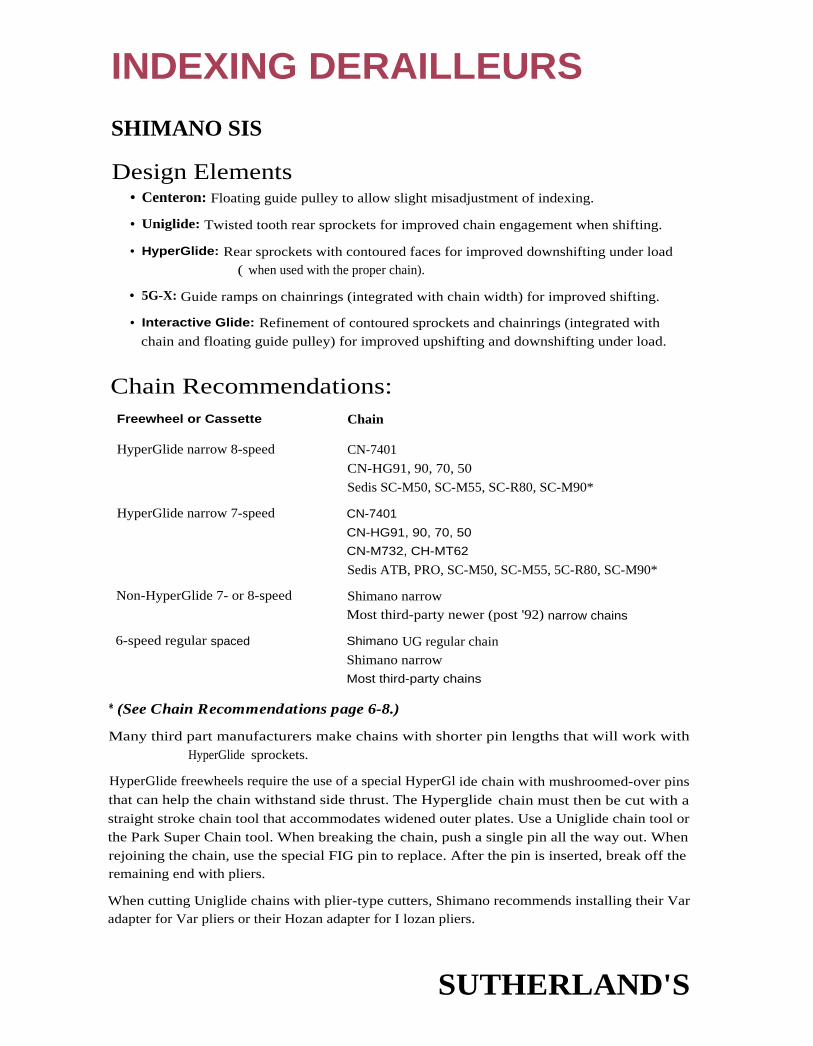
Freewheel or Cassette Chain
HyperGlide narrow 8-speed
HyperGlide narrow 7-speed
Non-HyperGlide 7- or 8-speed
6-speed regular spaced
CN-7401
CN-HG91, 90, 70, 50
Sedis SC-M50, SC-M55, SC-R80, SC-M90*
CN-7401
CN-HG91, 90, 70, 50
CN-M732, CH-MT62
Sedis ATB, PRO, SC-M50, SC-M55, 5C-R80, SC-M90*
Shimano narrowMost third-party newer (post '92) narrow chains
Shimano UG regular chain
Shimano narrowMost third-party chains
INDEXING DERAILLEURS
SHIMANO SIS
Design Elements• Centeron: Floating guide pulley to allow slight misadjustment of indexing.
• Uniglide: Twisted tooth rear sprockets for improved chain engagement when shifting.
• HyperGlide: Rear sprockets with contoured faces for improved downshifting under load( when used with the proper chain).
• 5G-X: Guide ramps on chainrings (integrated with chain width) for improved shifting.
• Interactive Glide: Refinement of contoured sprockets and chainrings (integrated withchain and floating guide pulley) for improved upshifting and downshifting under load.
Chain Recommendations:
* (See Chain Recommendations page 6-8.)
Many third part manufacturers make chains with shorter pin lengths that will work with
HyperGlide sprockets.
HyperGlide freewheels require the use of a special HyperGl ide chain with mushroomed-over pinsthat can help the chain withstand side thrust. The Hyperglide chain must then be cut with astraight stroke chain tool that accommodates widened outer plates. Use a Uniglide chain tool orthe Park Super Chain tool. When breaking the chain, push a single pin all the way out. When
rejoining the chain, use the special FIG pin to replace. After the pin is inserted, break off theremaining end with pliers.
When cutting Uniglide chains with plier-type cutters, Shimano recommends installing their Varadapter for Var pliers or their Hozan adapter for I lozan pliers.
SUTHERLAND'S

Dora-Ace 8-speed , Dura-Ace Dura-Ace 8-speed, Integrated-8
SL-7402, 5LBS50-8, 5T-7400
515 8-speed , Dura-Ace RD-7402
Dura-Ace 7-speed Dura-Ace Dora-Ace 7-speed SL-740l SIS 7-speed Dora-Ace RD-7402or RD-7401
Dura-Ace 6-speed Dura-Ace Dora-Ace 6-speed SL-7400 S15 6-speed Dura-Ace RD-7402,RD - 7401, or RD-7400
INDEXING DERAILLEURS
ABOUT THE DERAILLEUR CAPACITY CHARTSThe numbers listed in the derailleur capacity charts have been compiled from SunTour's literature.
The capacities listed are for "normal conditions." Drop-out geometry, chain ring sizes, hub posi-
tion, chainstay geometry, and other factors may increase or decrease a given derailleur's capacity.
Max. Chainring Difference = Largest chainring minus the smallest.
Total Capacity = largest freewheel sprocket minus smallest, plus the Max. Chainring Difference.
Max. Freewheel Teeth = Largest freewheel sprocket.
Blank Spaces indicate no listing in the manufacturer's literature.
SHIMANO SIS LEVERSDura-Ace levers and derailleurs must he used together. Dura-Ace levers will not work with stan-
dard 515 derailleurs and standard 515 levers will not work with Dura-Ace derailleurs.
Standard SIS levers can be used with any 515 rear derailleur except for Dura-Ace. Uniglide free-wheels and cassettes can be used with any chain. HyperGlide cassettes need compatible chains,
(see page 7-2). Interactive Glide cassettes should be used wit h Interactive Glide (or compatible)
chains, Interactive Glide rear derailleurs and Interactive Glide chainrings. Any rear derailleur can
be used with HyperGlide or Uniglide freewheels and cassettes, though the shifting may need to
be adjusted more often when using an Interactive Glide rear derailleur.
Different speed levers and freewheels or cassettes cannot be interchanged. 6-, 7- and 8-speed
freewheels, cassettes and levers are designed for different cog-center-to-cog-center spacing.
6-speed rear freewheels and cassettes are spaced approximately 5.55mm from cog-center-to-cog-center (except between the 4th and 5th cogs, counting from the inside), 7-speed is approximate-ly 5.0mm (except between the 5th and 6th cogs, counting from the inside), and 8-speed is
approximately 4.95mm average from cog-center-to-cog-center.
Shimano Index System Levers Model Freewheel/
Categories 515 Type Lever Models Cassette Rear Derailleur
(continued)
SUTHERLAND'S

ModelCategories 515 Type Lever Models
Freewheel/Cassette
Standard' 8-speed Standard" Any non-Dura-Ace 8-speed lever 515 8-speed
Standard1 7-speed Standard" Any non-Dura-Ace 7-speed lever2 515 7-speed3
Standard" 6-speed
(or less)
Standard" Any non-Dura-Ace 6-speed
(or less) lever2
SIS 6-speed
(or less)
Rear Derailleur
Any 8-speed rearderailleur except Dura-Ace
Any 7- or 8-speed rearderailleur except Dura-Ace
Any 6-, 7-, or 8-speed rearderailleur except Dora-Ace
INDEXING DERAILLEURS
SHIMANO SIS LEVERS (CONT'D)
Shimano Index System Levers (cont'd)
1 Do not confuse standard SIS with standard, or regular (vs. narrow), freewheel spacing. Standard 515 isnon-Dura-Ace SIS.
2 600 Ultegra 51.-6400 and SL-BS-50 levers can be modified for 6- or 7-speed use. For 6-speed, hook the adaptershim into the cable groove, reinove the adapter for 7-speed use.
3 When using an Interactive Glide cassette, also use an Interactive Glide chain, rear derailleur and chainwheels.An interactive Glide rear derailleur will work with a normal HyperGlide or Uniglide rear cluster, but may needto be adjusted more often.
SHIMANO SIS DROP-OUT DIMENSIONS1 - he following are therecommended dimen-sions for optimumshifting performanceand the Shimano drop-outs that meet thesedimensions.
L 0 X Drop-out Model
24mm 30-35' 4-12mm Shimano-EF FE-EF20
26mm 30-35° 6-12mm Shimano-SF FE-SF20
28mm 25-30" 6-12mm
29mm 25-30° 6-12mm Shimano-SFR FE-5121Shimano-SFRW FE-S122
30mm 25-30' 7.5-12mm
SUTHERLAND'S

Rear derailleur cage viewed from the back.
Pulley Centerto
Pulley Center
INDEXING REAR DERAILLEURS
SHIMANO SIS REAR DERAILLEUR CAPACITIES(Please see notes, "About the Derailleur Capacity Charts," on page 7-3.)
Derailleurs listed here are SIS compatible. Some derailleurs with identical names are not SIS com-
patible. Carefully check model numbers stamped into the frame, on the back of the body.
Dura-Ace levers will not work with standard derailleurs and standard levers will not work with
Dura-Ace derailleurs.
Shimano SIS Rear Derailleurs
Model No. Max. Freewheel TeethStamped Maximum
Model in Back Chain ring Total Dropout EF Dropout SFCategories of Body SIS Type Difference Capacity L=24 L=26
Dura-Ace 8-, 7-, & 6-speed RD-7402 Dura-Ace 14T 26T 26T
(See page 7-9 for older non- RD-7401 Dura-Ace 13T 26T 26T
indexing model numbers.) RD-7400 13T 26T 26T
Standard 6-, 7-, & 8-speed• 600 Ultegra RD-6401 Standard 13T 28T 28T
• 600 Ultegra RD-6400 14T 26T 28T
• 600 EX* RD-6208 13T 28T 28T
• Sante RD-5000 13T 24T 24T
RD-5001 13T 24T 24T
• Sante–Medium Cage (LS) RD-5001 13T 28T 23T 281
* (See page 7-9 for older models.)
Pulley Pins
Model Length Width Notes
Road 8-speed 12.8 5mm 3mm allen
Road 7-speed 14.0 5mm 3 mm alien
MTB 7-speed
'94 XTR 12.8 5mm 3mm alien
'94 Deore XT, LX 14.0 5mm 3mm allen
MTB 7-speed
'95 STX/RC, LX, DX, XT 16.1 5mm 3mm allen
'94 Alivio, Acera, Altus 15.8 5mm 8mm hex
ATB 6-speed
'95 MJ, MJ II 15.8 5mm 8mm hex
SUTHERLAND'S

INDEXING REAR DERAILLEURS
SHIMANO SIS REAR DERAILLEUR CAPACITIES (CONT'D)(Please see mites, "About the Derailleur Capacity Charts," on page 7-3.)
The capacity for the derailleurs listed on this page can be determined by the pulley center to pulley centerlength. (See the table at the bottom of the page.)
Model No. Stamped Model No. StampedModel Categories in Back of Body Model Categories in Back of Body
8-speed (works with • Exage Mountain RD-M4507- and 6-speeds) • Exage Trail RD-M350• XTR RD-M900, RD-M910 • Exage Country RD-M250
• Deore XT RD-M737 • 200GS, 200CX RD-M200• Deore LX RDM565 • 1 00GS RD-M100
• 1 05 SC RD-1056 • Altus A10 RD-AT10
• RX100 RD-A551• Altus A20 RD-AT20• Altus C10 RD-CT10
Standard 6- fit 7-speed(may not workwith 8-speeds)• Deore XT
• Deore DX• Deore
RD-M735, RD-M732,RD-M730
RD-M650RD-MT60, RD-MT62
• L (Light Action)Note: Models L532,L523, and L525 are SIScompatible only in theSS (short cage) model.
• 700 CX• 400 CX
RD-L554, RD-L553,RD-L532, RD-L523,RD-L525
RD-C700RD-C400
• Deore LX
• (Exage) Mountain LX
• STX-RC
RD-M550, RD-M560,RD-M563RD-452
RD- 3MC3
• 105SC• 1 05
• RX100
RD 1055RD-1051, RD-A550
RD-A553, RD-A550
• STX RD-MC32, RD-MC31,RD-MC30
• (Exage) Sport LX
• Exage Sport
RD-A452
RD-A450• Alivio RD-MC1 2, RD-MC11,
RD-MC10• Exage Action RD-A350• Exage Motion RD-A250
• Acera-X RD-M290 • RSX RD-A410
• Exage ES RD-M520 • Exage 500EX RD-A500• Exage LT RD-M320 • Exage 400EX RD-A400
• Exage 500LX, 500CX RD-M500-•Exage 300EX RD A300
• Exage 400LX RD-M400 • ( Marked SIS, as are RD-L541• Exage 300LX(continued next column)
RD-M300 other models.)
Case Length PulleyMax. Freewheel Teeth
Designation Center Drop-out Drop-out Drop-outExample: to Pulley 515 Chainring Total EF SF SFR, SFRWRD-452-SGS Center Type Difference Capacity L=24 L=26 L=29
55 or no designation 56mm Standard 1 3T 28T 28TGS 75mm 20T 34T* 26T 30TSGS 86.5mm 20T 38T 28T 32T
1990 Shimano Service Handbook lists GS Total Capacity as 36T.
SUTHERLAND'S

INDEXING REAR DERAILLEURS
SHIMANO SIS REAR DERAILLEURS(Please see notes, "About the Derailleur Capacity Charts," on page 7-3.)
Model Categories
Model No.Stamped inBack of Body
MaximumSIS Chainring TotalType Difference Capacity
MaximumFreewheelTeeth
Standard 6-speed thatcan fit PR20 drop-out• ( marked SIS,
as are other models)RD-M531 Standard 36T 30T*
Standard 6-speedwith gear hanger• ( marked Shimano SIS, RD-R552-SS
as are other models) RD-R552-GSStandard 13T
20T28T36T
28T30T
RD-CT90-GS**,SSRD-1Y20-SS, RD-TY70-SS,
RD-TY15-5513T 28T 24-28T
RD-M11 0-GS, RD-CT20-GS, 20TRD-TY70-GS, RD-TY15-GS
34T 28T
RD-TY20-GS 20T 34T 30TRD-MJ10-SS, RD-MJ05-SS 13T 28T 28TRD-MJ05-GS 20T 34T 24T
Standard 5-speedwith gear hanger• ( marked Shimano 515,
as are other models)RD-R552-SSRD-R552-SGS
Standard
I
28T36T
28T30T
* Use Shimano drop-out SF or PR20.** Fits 7-speed.
SHIMANO OLDER NON-SIS INDEXING REAR DERAILLEURSThese derailleurs must be used with Shimano's corresponding levers for indexing to work. The Positron listedbelow must be used with the corresponding lever and push-pull cable.
Model Categories
Model No.Stamped inBack of Body
MaximumChainringDifference
TotalCapacity
MaximumFreewheelTeeth
Dura -Ace AX RD-7300 13T 26T 24T600 AX RD-6300 13T 28T 28TAdamas AX RD-AD10 1 3T 28T 28T
Positron DG-100 1 3T 34T 34TPositron AX RD-AX10 13T 28T 28T
Positron-FH* RD-PF10* 13T 28T 28T*Positron-FH (medium cage)* RD-PF20* 1 3T 32T 32T*Positron-FH 400* RD-PF40* 1 3T 28T 28T*Positron-FH EM* RD-PF30* 1 3T 32T 321*
Positron-II* RD-P210* 1 3T 28T 281*Positron-111* RD-P312* 1 3T 28T 28T*Positron-400* RD-P240* 13T 28T 28T*
* For use with Shimano Front Freewheeling setup only.
SUTHERLAND'S

Short CageLong CageSuper Long Cage
SSGSSGS
56mm75mm86.5mm
Model
Model No.Stamped inBack of Body
MaximumChainwheelDifference
TotalCapacity
MaximumFreewheelTeeth
• Deore (medium cage) RD-DE10 20T 301 301(long cage) RD-DE20 20T 34T 34T
• Deore XT (w/Superplate) RD-M 700-SP 40T* 34Tn Deore XT RD-M700 22T 40T 34T• 600 RD-6100 1 3T 1 3T 28Tn 600 (long cage) RD-6101 1 3T 13T 34T• 600 AX RD-6300 1 3T 28T 281• 600 EX** RD-6200 1 3T 28T 281
RD-6207 1 3T 281 281• 600 EX (long cage) RD-6210 1 3T 34T 341
RD-6207-GS 13T 34T 34Tn 105 RD-A105 13T 28T 28T
RD-A105-GS 13T 34T 34Tn L (Light Action) RD-L512
The Light Actionderailleurs Fisted in thenext column have thecapacities listed accordingto the cage lengths
RD-L513RD-L514RD-L522RD-L523RD-L525RD-L532
SS— Short Cage 28T 281GS— Long Cage 34T 34TSGS— Super Long Cage 40T 341
NON-INDEXINGREAR DERAILLEURS
SHIMANO NON-INDEXING REAR DERAILLEURS(Please see notes, "About the Derailleur Capacity Charts," on page 7-3.)
Derailleurs that have cage length designations as part of the model number measure as follows:
1 Cage Length Designation Pulley CenterExample: RD-L513-SGS Cage Size to Pulley Center
For many of these derailleurs, no drop-out dimension (I.) was given in Shimano's literature.
Generally, the short cage derailleurs use a 24mm drop-out, while the longer cage derailleurs need
a 26mm or longer drop-out. We have noted where Shinano made a specific recommendation.
Shimano Non-Indexing Rear Derailleurs
* This is 42T when equipped with drop-out that has a 29mm L dimension.
** (See page 7-5 for newer models.)
SUTHERLAND'S

NON-INDEXINGREAR DERAILLEURS
Shimano Non-Indexing Rear Derailleurs (cont'd)
Model
• ZThe Z derailleurs listed inthe next column have theircapacities listed according tocage lengths
SS- Short cageGS- Long cageSGS- Super Long Cage
Model No. Maximum MaximumStamped in Chainring Total FreewheelBack of Body Difference Capacity Teeth
RD-Z501RD-Z503RD-Z505
30T34T40T
28T34T34T
Older Models (alphabetically)
• AL-11 RD-AL11 22T 40T 34T• Altus-LT RD-AT12 13T 28T* 28T*• Altus-LT (long cage) RD-AT22 13T 34T 34T• Altus-ST RD-AT11 13T 28T* 28T*• Altus-ST (long cage) RD-AT21 13T 34T 34T
• Crane DB-100 13T 28T 28T• Crane-GS DB-110 13T 34T 341
• Dura-Ace** RD-7100 1 3T 26T 26T• Dura-Ace EX RD-7200 1 3T 26T 26T
• Eagle-II RD-EG10 13T 34T 34T• Lark II RD-LK10 13T 34T 34T• Lark-Mini RD-LK20 1 3T 28T 28T
• RS RD-R511 1 3T 34T 34TRD-RS12 13T 34T 34T
• Sky Lark RD-SL10 13T 34T 34T• Titlist RD-TL10 13T 28T 28T• Titlist-G5 RD-TL11 1 3T 34T 34T
• Tourney RD-TN10 13T 28T 28T• Tourney-GS (long cage) RD-TN11 13T 34T 34T
I • Tourney RD-TY10-55 1 3T 30T 30T• Tourney-GS (long cage) RD-TY10-GS 1 3T 34T 34T
• 500 DC-100 13T 28T 28T• 500-GS DC-110 1 3T 34T 34T• 400 DC-400 1 3T 28T 28T8• 400-GS DC-410 13T 34T 34T• 400 FF RD-401 F 13T 34T 34T
* Add 2 teeth with a drop-out that has a 29mm L dimension.
** (See page 7-5 for newer models.)
SUTHERLAND'S

FRONT DERAILLEURS
SHIMANO FRONT DERAILLEUR CAPACITIES(Please see notes, "About the Derailleur Capacity Charts," on page 7-3.)
Half-StepRefers to a gearing setup with chainrings that are close enough in tooth number to make a front
shift that is roughly haf that of a rear shift (% increase or decrease in gear inches). In commonsetups, this is a chainring difference of 4 or 5 teeth. This setup requires a front derailleur whose inner
arid outer cages are close in height (matching the closeness of the diameters of the chainrings).
Alpine (sometimes called "Crossover")Refers to a gearing setup featuring chainrings that are typically 10-12 teeth apart. This makes for dis-tinct ranges of gears (one for each chainring), as opposed to the evenly dispersed front and rear shiftsfound with a "Half-Step" setup. "Alpine" derailleurs have inside and outside plates that differ con-siderably in height, thus allowing the chain to be guided over the large shifts between chain rings.
Shimano Indexing Front DerailleursIndexing front derailleurs must use their corresponding shift levers.
ModelCapacity
Model No. Min. Max.Half-Step/Alpine
Clamp Diameteror Braze-On (B/O)
• Exage Sport FD-A450* 3T 14T half-step 28.0-28.6, 8/0FD-A451
FD-A350*
FD-A351
• Exage Mountain** FD-M450* 20T*** alpine 28.0-28.6, 31.8, 34.9, 8/0FD-M451
Shimano Dual SIS-Indexing Front DerailleursICapacity
Model Model No. Min. Max.Half-Step/Alpine
Clamp diameteror Braze-On (B/O)
• XTR '94
• Deore XT
• Deore DX
• Deore LX
• 700CX
• Deore LX-HDC
• STX-SE
• STX
FD-M900
FD-M737
FD-M650
FD-M560
FD-C700
FD-M563
FD-MC31
FD-MC32
10T1
10T1
8T1
10T
26T
22T3
26T
26T
22T3
22T3
22T3
22/42 3
alpine
alpine
alpine
alpine
28.0-28.6,
28.0-28.6,
28.0-28.6,
28.0-28.6,
28.0-28.6,
28.0-28.6,
28.0-28.6,
28.0-28.6,
31.8, 34.9
31.8, 34.9,
31.8, 34.9
31.8 - 34.9
31.8, 34.9
31.8, 34.9
31.8, 34.9
31.8, 34.9
8/0
SUTHERLAND'S

FRONT DERAILLEURS
Shimano Dual SIS-Indexing Front Derailleur (cont'd)
Model Model No.CapacityMin. Max.
Half-Step/ Clamp DiameterAlpine or Braze-On (B/O)
• Alivio
• Acera-X 2
• Altus-050Altus-CT902
• Tourney
• MJ
• MJ 112
• 400 CX '94
• Dura-Ace '93
FD-MC122FD-MC11FD-MC10
FD-M290
FD-CT50FD-CT90-E
FD-TY30-65
FD-MJ10FD-MJ12
FD-MJ05
FD-C400
FD-7410
8T8T
8T
10T8T
10T
8T10T
6
1 8/42322T3
1 8/42T3
22T1 4/38T3
22T
18T1 4T
14T3
22T3
15T
alpine
alpine
alpinealpine
alpine
alpinehalf-step
alpine
half-step
28.0 - 28.6,28.0 - 28.6,28.0 - 28.6
28.0 - 28.6,
28.0 - 28.628.0 - 28.6,
28.0 - 28.6
28.0 - 28.6
28.0 - 28.6
28.0 - 28.6,
28.0 - 28.6
31.8,31.8
31.8
31.8
31.8,
34.9
34.9
1 Top-middle capacity
2 "Easy Set" Systems use a bracket that sets position and attaches to special bottom bracket.
3 These derailleurs are made to work with smaller Compact Drive chainrings.
* Narrow chains cannot be used with these derailleurs. Shimano recommends the regular width UG chain only.
** Shimano recommends that this derailleur he used with under-the-bottom bracket cable routing only.
*** 241 when used in the friction mode.
Shimano Non-Indexing Front Derailleurs
Model Model No.Half-Step/Alpine
CapacityMin. Max.*
Clamp Diameteror Braze-On (B/O)
• Dura-Ace FD-7403 half-step 15T 28.0-28.6, B/O
FD-7410 half-step 15T 28.0-28.6, B/O
• Deore DX FD-M650 alpine 26T 28.0-28.6
• Deore LX FD-M550 alpine 26T 28.0-28.6, 31.8, 34.9
• Deore XT FD-M700 alpine 81 22T 28.6
FD-M730-HS half-step 5T 26T 28.0, 28.6, 31.8
FD-M730-AL alpine 8T 26T 28.0, 28.6, 31.8
FD-M735 alpine 26T 28.0-28.6, 31.8, 34.9
• Deere XT II FD-M732-HS half-step 5T 24T 28.0, 28.6, 31.8
FD-M732-AL alpine 8T 24T 28.0, 28.6, 31.8
• Sante FD-5000 half-step 14T 28.6, B/0
• 600 Ultegra FD-6400 half-step 3T 14T 28.0-28.6, B/0
* Shimano recommends subtracting 4 teeth from maximum capacity for Biopace. Subtract 2 teeth for Biopace HP.
SUTHERLAND'S

FRONT DERAILLEURS
Shimano Non-Indexing Front Derailleurs (cont'd)(See page 7-13 for older models.)
Model Model No.Half-Step/Alpine
CapacityMin.
Clamp DiameterMax.* or Braze-On (B/O)
• 600 EX FD-6207 half-step 3T 18T 28.6, B/0
• 1 05 FD-1050 half-step 3T 14T 28.0-28.6, RIO
FD-1055 half-step 14T 28.0-28.6, B/O
• 1 05SC FD-1056 half-step 15T 28.0-28.6, 31.8, 34.9
• Z FD-Z254 half-step 1 4T 28.0-28.6
FD-Z255 alpine 22T 28.0-28.6
FD-Z260 half-step 1 4T 28.0-28.6
FD-Z261 alpine 22T 28.0-28.6
• XTR '93 FD-M900 alpine 26T 28.0-28.6
• Mountain LX FD-M452-HS half-step ST 26T 28.0, 28.6
FD-M452-AL alpine 8T 26T 28.0, 28.6
• Sport LX FD-A452 half-step 14T 28.0-28.6, B/0
• RX-100 FD-A550 half-step 1 4T 28.0-28.6, B/0
FD-A551 half-step 15T 28.0-28.6
FD-A553 alpine 26T 28.0-28.6
• Exage 300 EX FD-A300 half-step 14T 28.0-28.6
• Exage 400 EX FD-A400 half-step 1 4T 28.0-28.6, B/O
• Exage 500 EX FD-A500 half-step 1 4T 28.0-28.6, 8/0
• Altus Al 0 FD-AT10 alpine 26T 28.0-28.6, 31.8
• Altus A20 FD-AT20 alpine 22T 28.0-28.6
• Altus C10 FD-CT10 alpine 22T 28.0-28.6
• Altus C20 FD-CT20 alpine 22T 28.0-28.6
• Exage 300 LX FD-M300 half-step 1 4T 28.0-28.6
• Exage 400 LX FD-M400 alpine 26T 28.0-28.6, 31.8, 34.9
• Exage 500 LX FD-M500 alpine 26T 28.0-28.6, 31.8, 34.9
• Exage LT FD-M320I
alpine 26T 28.0-28.6, 31.8, 34.9
• Exage ES FD-M520 alpine 26T 28.0-28.6, 31.8, 34.9
• Exage Country FD-M250 alpine 8T 221 28.0-28.6
* Shimano recommends subtracting 4 teeth from maximum capacity for Biopace. Subtract 2 teeth for Biopace HP.
SUTHERLAND'S

INDEXING DERAILLEUR
Shimano Non-Indexing Front Derailleurs (cont'd)
Model Model No.Half-Step/Alpine
CapacityMin. Max.*
Clamp Diameteror Braze-On (B/O)
• Exage Motion FD-A250 half-step 1 7T 28.0-28.6
• Exage Trail
• 400CX
• 200CX
• 200 GS
FD-M350
FD-M351
FD-C400
FD-M202-C
FD-M200
alpine
alpine
alpine
alpine
22T
22T
22T
26T
22T
28.0-28.6,
28.0-28.6,
28.0-28.6,
28.0-28.6,
28.0-28.6
29.0, 31.8,
29.0, 31.8,
31.8, 34.9
31.8, 34.9
34.9
34.9
• 1 00GS
• 70GS
FD-M100
FD-TY70
22T
22T
28.6, 31.8,
28.0-28.6
34.9
• (no name) FD-AX50 half-step 3T 14T 28.0-28.6
• (no name) FD-AX55 alpine 8T 22T 25.4, 28.6
• Youth FD-TY20 half-step 14T 28.0-28.6
• Tourney FD-TY25 alpine 22T 28.0-28.6
FD-TY21 alpine 22T 28.0-28.6
FD-TY15-SS half-step 1 4T 28.0-28.6
FD-TY15-GS alpine 22T 28.0-28.6
Shimano Non-Indexing Front Derailleurs— Older Models (pre-1985) alphabetically
Model Model No.Half-Step/Alpine
CapacityMin. Max.*
Clamp Diameteror Braze-On (B/O)
• Adamas AX FD-AD10 half-step 1 41 28.6
• Altus FD-AL11 alpine 8T 22T 28.6, 25.4
• Altus FD-AT11 ' half-step 1 4T 28.6, 25.4
• Altus-LT FD-AT12 half-step 14T 28.6, 25.4
• Altus-ST FD-AT-11 half-step 1 4T 28.6, 25.4
• Deore FD-DE10 alpine 20T 28.6
• Deore FD-MT60-HS half-step 51 26T 28.0, 28.6, 31.8
FD-MT60-AL alpine 8T 26T 28.0, 28.6, 31.8
• Deore II FD-MT62-HS half-step ST 24T 28.0, 28.6, 31.8
FD-MT62-AL alpine 8T 24T 28.0, 28.6, 31.8
* Shimano recommends subtracting 4 teeth from maximum capacity for Biopace. Subtract 2 teeth for Biopace HP.
SUTHERLAND'S
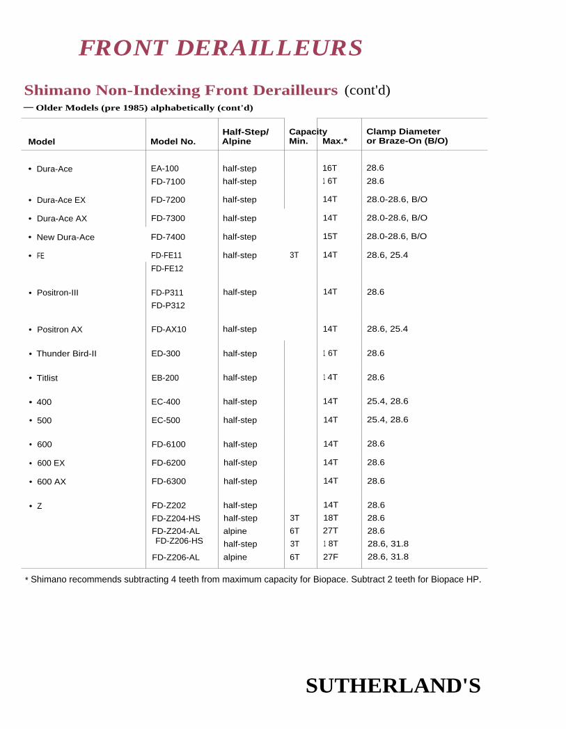
FRONT DERAILLEURS
Shimano Non-Indexing Front Derailleurs (cont'd)— Older Models (pre 1985) alphabetically (cont'd)
Model Model No.Half-Step/Alpine
CapacityMin. Max.*
Clamp Diameteror Braze-On (B/O)
• Dura-Ace EA-100 half-step 16T 28.6
FD-7100 half-step 1 6T 28.6
• Dura-Ace EX FD-7200 half-step 14T 28.0-28.6, B/O
• Dura-Ace AX FD-7300 half-step 14T 28.0-28.6, B/O
• New Dura-Ace FD-7400 half-step 15T 28.0-28.6, B/O
• FE FD-FE11 half-step 3T 14T 28.6, 25.4
FD-FE12
• Positron-III FD-P311 half-step 14T 28.6
FD-P312
• Positron AX FD-AX10 half-step 14T 28.6, 25.4
• Thunder Bird-II ED-300 half-step 1 6T 28.6
• Titlist EB-200 half-step 1 4T 28.6
• 400 EC-400 half-step 14T 25.4, 28.6
• 500 EC-500 half-step 14T 25.4, 28.6
• 600 FD-6100 half-step 14T 28.6
• 600 EX FD-6200 half-step 14T 28.6
• 600 AX FD-6300 half-step 14T 28.6
• Z FD-Z202 half-step 14T 28.6
FD-Z204-HS half-step 3T 18T 28.6
FD-Z204-AL alpine 6T 27T 28.6FD-Z206-HS half-step 3T 1 8T 28.6, 31.8
FD-Z206-AL alpine 6T 27F 28.6, 31.8
* Shimano recommends subtracting 4 teeth from maximum capacity for Biopace. Subtract 2 teeth for Biopace HP.
SUTHERLAND'S

CONTENTS
8
Sun TourDesign Elements
Accushift .................................. 2
AccushiftPlus ........................... 2
Plug and Play .......................... 2
Chain recommendations ............2
About derailleur capacity
charts ..................................... 3
Cassettes and freewheels .......... 3
Shifters ......................................... 4
Drop-out recommendations .... 5
Rear derailleur capacitycharts .................................. 6-7
Non-Accushift indexingrear derailleur capacity ........ 8
Non-indexing rear derailleur
capacity .................................. 9
Older non-indexing rearderailleur capacity ........... 9-10
Indexing front derailleursHalf-step/Alpine ................... 11
Accushift................................ 11Non-Accushift ....................... 1 1
"Top-pull" ............................ 11
Front derailleur capacity ....12-14
SUTHERLAND'S

Freewheel Chain
PowerFlo 8-, 7-speed narrow spaced
AccushiftPlus 8-speed narrow spaced
PowerFloSedis SC-M90*, Sedis MC-50, Sedis MC-55
PowerFloSedis SC-M90*
AccushiftPlusSedis ATB*, Sedis MC-50*, Sedis MC-55*
AccushiftPlus 7-speed narrow spaced
AccushiftPlusSedis ATB*, Sedis MC-50*, Sedis MC-55*
AccushiftPlus 6-, 5-speed regular spaced
AccushiftPlusSedis ATB*, Sedis MC-50*, Sedis MC-55*SunTour Superbe Pro, Pro, Cyclone, GPX
AccushiftPlusSedis ATB*SunTour Superbe Pro, Pro, Cyclone, GPXHKK "7"DID Lanner
Accushift 7-speed narrow spaced
Accushift 6-, 5-speed regular spaced
INDEXING DERAILLEURS
SUNTOUR ACCUSHIFT AND ACCUSHIFTPLUS
Design Elements• Overshift built into shift levers.
• System has less built-in "play" than others.
n S-I adjusting notes see page 8-4.
SunTour Accushift is very different from Shimano SIS.
Overshift is built into the levers (overshi ft of I mm of cable travel). This pushes the chain center-li ne past the cog centerline to complete the shift. The guide pulley then settles back into a posi-
tion where it is centered under the cog.
The guide pulley lines up exactly under each freewheel cog without as much "play" as other systems.
Chain Recommendations
* (See Sedisport chain notes on page 6-8 in the Sachs-huret section when using Sedis chain.)
SUNTOUR PLUG AND PLAY (SHIMANO COMPATIBLE)
Design Elements• Shimano compatible SunTour derailleurs have parallelogram with the same geometry as
Shimano Standard SIS derailleurs and a "floating" guide pulley.
• Shimano compatible SunTour shifters pull the same amount of cable as a Shimano SIS shifter.
• Shimano compatible SunTour freewheels are spaced like a Shimano SIS freewheel.
SUTHERLAND'S

Shimano SpacingAccushift (SunTour) Spacing
7- AND 8-SPEED NARROW SPACEDCassettes - narrow spacedPowerFlo - 15 splines-sprockets marked APIIAccushift Plus II - 15 splines
Accushift Plus - 15 splines
Freewheels - narrow spacedPowerFlo - sprockets marked APIIAccushift Plus
AccushiftWinner Pro
Winner
Ultra 7
Cassettes - narrow spacedPowerFlo Rear (PFR) - 9 splines-sprockets marked PF(also called PowerFlo 3 and Plug and Play)
Freewheels - narrow spacedPowerFlo Rear (PFR)-sprockets marked PF(also called PowerFlo 3 and Plug and Play)
6- AND 5-SPEED REGULAR SPACEDFreewheels only - regular spacedPowerFlo-sprockets marked APIIAccushift PlusAccushiftWinner Pro
Winner
(not Ultra 6)
Freewheels only - regular spacedPowerFlo Rear (PFR)-sprockets marked PF
INDEXING DERAILLEURS
ABOUT THE DERAILLEUR CAPACITY CHARTSThe numbers listed in the derailleur capacity charts have been compiled from SunTour's liter-
ature. The capacities listed are for "normal conditions." Drop-out geometry, chainring sizes,
hub position, chainstay geometry, and other factors may increase or decrease a given
derailleur's capacity.
Max. Chainring Difference = Largest chainring minus the smallest.
Total Capacity = Largest freewheel sprocket minus smallest, plus the Max. Chainring Difference.
Max. Freewheel Teeth = Largest freewheel sprocket.
Blank Spaces indicate no listing in the manufacturer's literature.
SUNTOUR CASSETTES AND FREEWHEELSCassettes and freewheels in each group have the same spacing and are listed in order of
decreasing performance.
SUTHERLAND'S

8-speed MicroDrive XC-Pro MD
XC-Comp MD
Superbe ProSL
Any 7-speed Accushift
narrow spaced
Any 6-speed Accushift regular spaced
FW-S100-K5 SX-100
Lever, Express Twist or ErgoTec Cassette/Freewheel Derailleur
Any 7-speed Accushift
narrow spaced freewheel
Any Accushift derailleur
except a-3000
Any 6-speed Accushift regular
spaced freewheel (not Ultra 6)
Any 6-speed Accushift regular
spaced freewheel (not Ultra 6)
Any Accushift derailleur
except a-3000
Use with cr.-3000
derailleur only
7-speed
Plug and Play compatible
ErgoTec ST-E520
Twist XR-50, XR-150
6-speed
Plug and Play compatible
Thumb XR-50
7-speed Shimano or
SunTour PowerFlo Rear (PFR)
SunTour PowerFlo Rear (PFR)
Any Shimano
standard 515 or
XR-50*, XR-150*
Any Shimano standard
515 or X R-50*,XR-150*
8-speed
Accushift
7-speed
Accushift
6-speed
Accushift
6-speed
a-3000
5-1**
SX-100
SX-100
7-speed
S-1**
5X-100
6 -speed
SX-100
5-speed
SX-100
INDEXING DERAILLEURS
SUNTOUR SHIFTERSAccushift down tube clamp-on index shifters have lever post flats that are often perpendicular to the down
tube while the braze-cans have lever post flats that are normally parallel to the down tube. If you run across
braze-ons that are mounted with the flats perpendicular you can use levers from a damp-on set. Another solu-
tion is to use GPX levers that are keyed to the large square portion of the braze-on rather than the post flat.
* For capacity of XR-50 and XR-150, (see note at bottom of page 8-6).
** To adjust S-I derailleur adjust so parallelogram is parallel to chainstay. Next select 2nd gear,then using index adjust screw, center guide pulley under 2nd smallest sprocket.
SUTHERLAND'S

INDEXING DERAILLEURS
SUNTOUR SHIFTER MARKINGSOlder SunTour Shift levers were marked as follows
-RE - regular spacing for 6- and 5-speed freewheels.
UL - Ultra (narrow) spacing for 7-speed freewheels.
F - Friction mode—non-indexing.
P - Power—ratcheted non-indexing.
SUNTOUR DROP-OUTRECOMMENDATIONSThe chart below has the recommended dimensions for
optimum shifting performance and some of the SunTourdrop-outs that meet these dimensions.
S-I has shift hanger that is brazed onto the underside ofthe chainstay. Use SunTour S-1 Braze on Boss AlignmentJig #TA-S100.
L ¢ X Drop-out Model
24mm 30-35° ideal-35° 3-7mm Superbe-Pro EF-230
SunTour-a DO-ALA1
DO-ALAODO-ALB1
DO-ALBO
26mm 30-35° ideal-35° 3-7mm Superbe-Pro EF-160
28mm 30-35° ideal-30° 3-7mm SunTour-GS EF-101
EF-1 70
EF-180
SunTour-GT EP-101EF-200
EF-140
30mm 30-35°
ideal-30°
3-7mm SunTour-SD EF-121
(vertical) EF-210
EF-220
SUTHERLAND'S

Rear derailleur cage viewed from the backMeasurement indicated is the pulley center to pulley center.
INDEXING REAR DERAILLEURS
SUNTOUR ACCUSHIFT AND ACCUSHIFT PLUSREAR DERAILLEUR CAPACITYwith Angle Adjusting Screw-on Derailleur
Lightweight Models Model No. ATB Models (cont'd) Model No.
• Superbe Pro RD-SBOO • XC Sport RD-X501n SL RD-SLOO • XC Sport 7000 RD-X500• Sprint 9000 RD-SP10 • XC-LTD RD-XLOO• GPX RD-GPOO • XC-Expert RD-XXOO• Radius RD-RA00 n XCD RD-XD1O• Ole RD-OLOO • X-1 Chroma RD-CROO• Cyclone 7000 RD-CL10 • X-1 RD-X100• Edge RD-EDOO • F5-E RD-FE00n Blaze RD-BE00 • ICE RD-XE00• VX RD-VXOO • XCM RD-XM00• RT RD-RTOO n ICI RD-XT00, XT01n FT01 RD-FT01 n XR100 RD-XR00n FTU RD-FUOO • XCU RD-XU00• a-5000 RD-5000 • AC-2000 RD-A200n a-3000 RD-2000 • AC-1000 RD-A100
• a-1500 RD-1500ATB Models Model No. • Scrambler II RD-5100n IC-Pro RD-XPOO n Scrambler RD-SR21• XC-9000 RD-XCOO • Honor RD-HNOO• XC-Comp RD-XC20 n S-1 RD-5100
Cage LengthDesignationExample:RD-XMOO-GX
PulleyCenterTo PulleyCenter
MaximumChainringDifference
TotalCapacity
Maximum Freewheel Teeth-
Drop-outL.24
Drop-out Drop-out1=26 1=28
SS - for SL — 121 24T 24T 241 26T
55 - Superbe Pro,Sprint, and GPX 47.5mm 1 2T 26T 26T 26T 28T
SS others 56.5mm 12T 28T 26T 28T 28T
GT 80mm 19T 34T 28T 30T-
32T
GX* 85mm 21T 401 281 30T 32T
* Reduce total capacity and maximum freewheel teeth by 2T for Plug and Play Shimano compatibleXR-50 and XR-150
SUTHERLAND'S

Models Model No.
• XC 9010 RD-XC10• XCD 6000 RD-X DOO• Edge 4050 RD-ED45• o-4050 RD-4050• XCE 4050 I RD-XE45
Models Model No.
• XCD 4050 RD-4050• Blaze 3040 RD-BE45• u-3040 RD-3040• XCM 3040 RD-XM34• a-3000 RD-3000
D/T Attachment
INDEXING REAR
SUNTOUR ACCUSHIFT REAR DERAILLEUR CAPACITIES with D/T attachments (1988, 1989 models only)
The capacities for the derailleurs on this page can be determined by measuring the lengthbetween pulley centers. See the tables below.
with SunTour, Campagnolo and Tange Drop-outs ( NR stands for not recommended).
Cage
_Pulley Max.Center Chain-to ring Total
6-speed Regular SpacingMaximum Freewheel Teeth
7-speed Narrow SpacingMaximum Freewheel Teeth
-Desig- Pulley Differ- Capac- Drop-out Drop-out Drop-out Drop-out Drop-outnation Center ence ity L=24 1=26 1=28 L=24 L=30 or less
SS 56.5mm 1 21 28T 26TH 26T 28T 26TA,G NRGX 85mm
20T 40T 28Tc 28T 32TH 28TD 32TD,F,H
with Shimano Drop -outs (NR stands for not recommended).
6-speed Regular Spacing 7-speed Narrow SpacingPulley Max. Maximum Freewheel Teeth Maximum Freewheel TeethCenter Chain- -- -
Cage to ring Total Drop-out Drop-out Drop-out Drop-out Drop-out Drop-outDesig- Pulley Differ- Capac- EF UF, SF SFR EF UF, SF SFRnation Center ence ity 1=24 1=26 1=28 1=24 L=26 L=28
SS 56mm 1 2T 28T 26T6 I 28T C NR 26TB 28Tc NRGX 85mm 20T 40T 26T1 30T1 32TK 26TD 30TD,F 32T-D,F,K
A For 261 freewheels, add D/T attachment with 2mm nd facing forward.
B For 24T freewheels, add D/T attachment with 2mm end facing forward.For 26T freewheels, add D/T attachment with 4mm end facing forward.
C For 26T - freewheels, add Da attachment with 2mm end facing forward.For 28T freewheels, add D/T attachment with 4mm end facing forward.
D Smallest three cogs must he 13, 15 and 17T.
E largest cog must be 28T.
F Largest cog must he 28, 30, or 321.
G Largest cog must he 24 or 26T.
H For 32T freewheels, add D/T attachment with 4mm end facing forward.
I For 26T freewheels, add D/T attachment with 4mm end facing forward.
J For 28T freewheels, add D/T attachment with 2mm end facing forward.For 301 freewheels, add D/T attachment with 4mm end facing forward.
K For 301 freewheels, add D/T attachment with 2mm end facing forward.For 321 freewheels, add D/T attachment with 4mm end facing forward.
SUTHERLAND'S

INDEXING REAR DERAILLEURS
SUNTOUR NON-ACCUSHIFT INDEXING REAR DERAILLEURS
MaximumMaximum FreewheelChainring Total Teeth
Model Model No. Difference Capacity L=26
• Mighty Click* RD-2700 13T 22T 30T• Mighty Click-GT*
L_
RD-2800 13T 34TI
34T
This model uses early indexing system; required Mighty Click levers.
SUTHERLAND'S

NON-INDEXINGREAR DERAILLEURS
SunTour Non-Indexing Rear Derailleurs
Model Model No.
Max. Chainring Diff./Total Capacity/Max. Freewheel
Drop-outL=24mm
Drop-outL=26mm
Drop-outL=28mm
Drop-outL=30mm
• Sprint RD-7000
• SVX-GT RD-7400 14T/ 32T/ 32T
• SVX-SS RD-7300 12T/ 26T/ 28T
• AT-1000 RD-AT10-GX 20T/ 40T/ 32T• RT-1 000 RD-RT1 0-SS 14T/ 28T/ 28T
• Seven-GT RD-SNOO-GT */34T/281 *1341/ 301
• Seven-SS RD-SNOO-SS */30T/ 28T
• Honor-GT RD-H000-GT */ 32T/ 34T• Honor-SS RD-1100 11T/ 28T/ 30T
SunTour Non-Indexing Rear Derailleurs— Older Models (pre-1987) alphabetically
Model Model No.
Max. Chainring—
Diff./Total Capacity/Max. Freewheel
Drop-outL=24mm
Drop-outL=26mm
Drop-outL=28mm
Drop-outL=30mm
• Allegro RD-AE00 11T/ 28T/ 26T 1 1T/ 28T/ 281R D-A E 00-G X 19T/ 39T/ 28T 19T/ 39T/ 30T 19T/ 39T/ 32T
• AG Tech RD-5000 10T/ 34T/ 37T• AG Tech-GTL RD-5600 19T/ 40T/ 37T
(extra long cage)
• AR RD-4200 15T/ 28T/ 26T
• AR-GT (long cage) RD-4400 13T/ 34T/ 34T
• ARX RD-4300 14T/ 28T/ 26T
• ARX (long cage) RD-4500 13T/ 32T/ 32T
• BL (short cage) RD-3200 1 3T/ 24T/ 24T• BL-S RD-3600 1 7T/ 30T/ 26T
(medium cage!)• BL-GT (long cage) RD-3300 1 3T/ 34T/ 34T
* Maximum Chainring Difference is not listed in SunTour literature.(continued)
SUTHERLAND'S

NON-INDEXINGREAR DERAILLEURS
SunTour Non-Indexing Rear Derailleurs (cont'd)— Older Models (pre 1987) alphabetically (cont'd)
Model Model No.
Max. Chainring Diff./Total Capacity/Max. Freewheel
Drop-outL = 24mm
Drop-out Drop-outL = 26mm L = 28mm
Drop-outL = 30mm
• Cyclone RD-6000 13T/ 24T/ 25T 14T/ 28T/ 26TRD-6200 13T/ 24T/ 25T 14T/ 30T/ 28TRD-6800 13T/ 24T/ 25T 17T/ 34T/ 30TRD-1 700 13T/ 24T/ 251
• Cyclone GT RD-1800 17T/ 32T/ 34T
• Cyclone Mark II RD-3500 14T/ 28T/ 26T
• Cyclone Mark II-GT RD-3700 12T/ 34T/ 34T(long cage)
• GT RD-1200 15T/ 36T/ 34T
• LePree-S RD-6100 14T/ 30T/ 28T• LePree-GT RD-6700 17T/ 34T/ 30T• MounTech RD-4900 13T/ 34T/ 34T• MounTech-GTL RD-5500 19T/ 40T/ 34T
• Seven RD-1900 13T/ 26T/ 26T
• Seven-GT RD-2000 11T/ 32T/ 34T
• Skitter* RD-1000 12T/ 28T/ 301
• Superbe Pro RD-3100 10T/ 20T/ 23TRD-5200 11T/ 251/ 261
• Superbe RD-2100 10T/ 20T/ 23T
RD-5300 1IT/ 22T/ 23T
• Superbe Tech-S RD-4700 15T/ 28T/ 26T(short cage)
• Superbe Tech-L RD-4800 13T/ 34T/ 34T(long cage)
• Superbe Tech-GTL RD-5400 191/40T/ 34T(extra long cage)
• Trimec RD-4600 1 3T/ 28T/ 28T• Trimec RD-6400 1 7T/ 30T/ 26T• XC RD-6300 17T/ 38T/ 34T
• VX RD-2200 11T/ 24T/ 26T• VX-GT RD-2400 13T7 34T/ 34T
• VX-S RD-2500 15T/ 28T/ 26T
• VGT RD-1500 18T/ 34T/ 30T• Volante RD-2600 10T/ 21T/ 24T
(short cage)• Volante-S RD-4100 15T/ 30T/ 28T
(long cage!)
* Low normal derailleur—cable pull shifts to smaller freewheel cog.
SUTHERLAND'S

Half-Step/ CapacityModel Model No. Alpine Min. 1 Max.2
• Mighty Click 10* FD-1800 half-step 18T
• Trimec FD-3600 alpine 24T
ClampDiameter
28.6
28.6
FRONT DERAILLEURS
SUNTOUR INDEXING FRONT DERAILLEURS(See notes, "About the Derailleur Capacity Charts," on page 8-3.)
Half-StepRefers to a gearing setup with chainrings that are close enough in tooth number to make a front shiftthat is roughly half that of a rear shift (% increase or decrease in gear inches). In common setups, thisis a chainring difference of 4 or 5 teeth. This setup requires a front derailleur whose inner and outer
cages are close in height (matching the closeness of the diameters of the chainrings).
Alpine (sometimes called "Crossover")Refers to a gearing setup featuring chainrings that are typically 10 to 12 teeth apart. This makes for dis-
tinct ranges of gears (one for each chainring), as opposed to the evenly dispersed front and rear shifts
found with a "Half-Step" setup. "Alpine" derailleurs have inside and outside plates that differ consid-
erably in height, thus allowing the chain to be guided over the large shifts between chainrings.
SunTour Accushift Indexing Front DerailleursOther models are also used with indexing shifters. XCE 4051 and Scrambler require
matching model shifters.
Half-Step/ Capacity ClampModel Model No. Alpine min. 1 Max. 2 Diameter
• XCE 4051 * FD-XE46-GX alpine 24T 28.6
• Scrambler* FD-4200 half-step 22T 28.6
SunTour Non-Accushift Indexing Front Derailleurst
SunTour "Top-Pull" Front Derailleur" Half-Step/ Capacity Clamp
Model Model No. Alpine Min.1 Max. 2 Diameter
• Top Pull FD-TPOO-GX alpine 6T 24T 28.6, 31.8
* Requires matching model indexing shift lever.
** "Top normal" derailleur (cable pull produces shift to smaller chainring).
Early indexing systems; required matching shift levers.
tt Cable is routed down to derailleur from above—requires appropriate braze-ons on frame.
1 When inner chainring is oval, add 21'; when outer chainring is oval, subtract 2T..
2 Subtract 4T when both chainrings are oval; subtract 2T when one chainring is oval.
SUTHERLAND'S

FRONT DERAILLEURS
SunTour Front Derailleurs— Lightweight Models
Model Model No.
Half-Step/
Alpine
ChainringDifference
Min.1 Max. 2
Clamp
Diameter
or Braze-On (B/O)
• Superbe Pro FD-SBOO-SS half-step 2T 1 6T 28.6, 28.0, 31.8, B/O
• Sprint 9000 FD-3900-SS half-step 2T 18T 28.6
• Sprint FD-SPOO-SSB half-step 2T 18T 28.6
• Cyclone 7000 FD-CL10-SS half-step 2T 18T 28.6, B/O
• GPX FD-GPOO-SS half-step 2T 1 6T 28.6, B/O
• Ole FD-OLOO-SS half-step 2T 1 8T 28.6, B/O
• Radius FD-RA00-SS half-step 2T 16T 28.6, 31.8, B/0
• a-5000 FD-5000-SS half-step 2T 1 8T 28.6, B/O
FD-5000-GT alpine 6T 22T 28.6
FD-5000-GX alpine 6T 24T 28.6
• Edge FD-ED0O-SS half-step 2T 18T 28.6, 31.8
• Edge 4050 FD-ED45-SS half-step 2T 1 8T 28.6, B/O
• a-4050 FD-4050-SS half-step 2T 1 8T 28.6, B/O
• Blaze FD-BE00-SS half-step 2T 1 8T 28.6, 31.8
• Blaze 3040 FD-BE34-SS half-step 2T 1 8T 28.6
• a-3040 FD-3040-SS alpine 6T 24T 28.6, B/O
• a-3000 FD-3000-SS half-step 2T 1 8T 28.6
• SVX FD-4300 half-step 2T 1 8T 28.6
• VX FD-VX00-SS half-step 2T 1 8T 28.6, 31.8
• AC-2000 FD-A200-SS half-step 2T 1 8T 28.6
• a-2000 FD-2000-SS half-step 2T 1 8T 28.6
• a-1500 FD-1500-55 half-step 2T 1 8T 28.6
• AC-1000 FD-RT10-SS half-step 2T 1 8T 28.6, 31.8
FD-AT10-GX alpine 6T 24T 28.6
• RT-1000 FD-RT10-SS half-step 2T 1 8T 28.6
• Allegro FD-AE00 half-step 2T 1 6T 28.6
• Seven FD-SNO0 half-step 2T 1 8T 28.6
• Spirt FD-1000 half-step 2T 1 8T 28.6
1 When inner chainring is oval, add 2T; when outer chainring is oval, subtract 2T.2 Subtract 4T when both chainrings are oval; subtract 21 when one chainring is oval.
SUTHERLAND'S
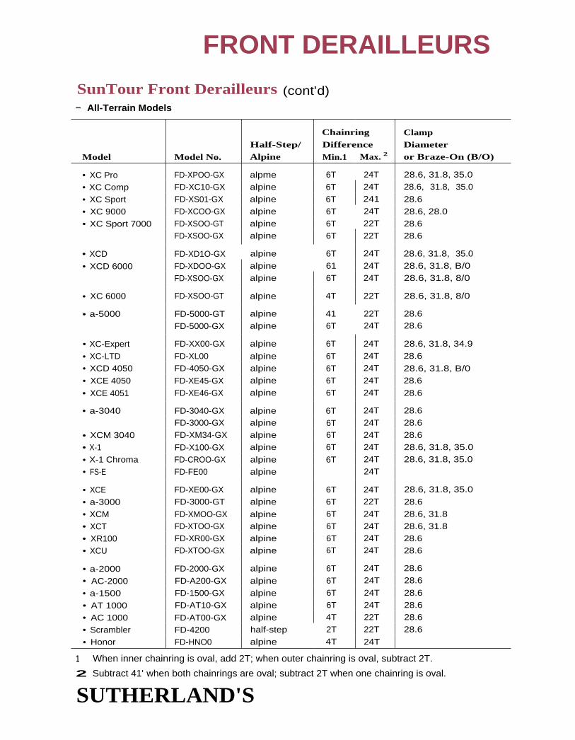
FRONT DERAILLEURS
SunTour Front Derailleurs (cont'd)- All-Terrain Models
Model Model No.
Half-Step/Alpine
Chainring
Difference
Min.1 Max. 2
ClampDiameteror Braze-On (B/O)
• XC Pro FD-XPOO-GX alpme 6T 24T 28.6, 31.8, 35.0
• XC Comp FD-XC10-GX alpine 6T 24T 28.6, 31.8, 35.0
• XC Sport FD-XS01-GX alpine 6T 241 28.6
• XC 9000 FD-XCOO-GX alpine 6T 24T 28.6, 28.0
• XC Sport 7000 FD-XSOO-GT alpine 6T 22T 28.6FD-XSOO-GX alpine 6T 22T 28.6
• XCD FD-XD1O-GX alpine 6T 24T 28.6, 31.8, 35.0
• XCD 6000 FD-XDOO-GX alpine 61 24T 28.6, 31.8, B/0
FD-XSOO-GX alpine 6T 24T 28.6, 31.8, 8/0
• XC 6000 FD-XSOO-GT alpine 4T 22T 28.6, 31.8, 8/0
• a-5000 FD-5000-GT alpine 41 22T 28.6
FD-5000-GX alpine 6T 24T 28.6
• XC-Expert FD-XX00-GX alpine 6T 24T 28.6, 31.8, 34.9
• XC-LTD FD-XL00 alpine 6T 24T 28.6
• XCD 4050 FD-4050-GX alpine 6T 24T 28.6, 31.8, B/0
• XCE 4050 FD-XE45-GX alpine 6T 24T 28.6
• XCE 4051 FD-XE46-GX alpine 6T 24T 28.6
• a-3040 FD-3040-GX alpine 6T 24T 28.6FD-3000-GX alpine 6T 24T 28.6
• XCM 3040 FD-XM34-GX alpine 6T 24T 28.6
• X-1 FD-X100-GX alpine 6T 24T 28.6, 31.8, 35.0
• X-1 Chroma FD-CROO-GX alpine 6T 24T 28.6, 31.8, 35.0
• FS-E FD-FE00 alpine 24T
• XCE FD-XE00-GX alpine 6T 24T 28.6, 31.8, 35.0
• a-3000 FD-3000-GT alpine 6T 22T 28.6
• XCM FD-XMOO-GX alpine 6T 24T 28.6, 31.8
• XCT FD-XTOO-GX alpine 6T 24T 28.6, 31.8
• XR100 FD-XR00-GX alpine 6T 24T 28.6
• XCU FD-XTOO-GX alpine 6T 24T 28.6
• a-2000 FD-2000-GX alpine 6T 24T 28.6
• AC-2000 FD-A200-GX alpine 6T 24T 28.6
• a-1500 FD-1500-GX alpine 6T 24T 28.6
• AT 1000 FD-AT10-GX alpine 6T 24T 28.6
• AC 1000 FD-AT00-GX alpine 4T 22T 28.6
• Scrambler FD-4200 half-step 2T 22T 28.6
• Honor FD-HNO0 alpine 4T 24T
1 When inner chainring is oval, add 2T; when outer chainring is oval, subtract 2T.
2 Subtract 41' when both chainrings are oval; subtract 2T when one chainring is oval.
SUTHERLAND'S

FRONT DERAILLEURS
SunTour Front Derailleurs (contd)— Older Models (pre-1987)
Model Model No.
Half-Step/Alpine
Chainring
Capacity
Min) Max. 2
Clamp
Diameter
• Superbe Pro FD-2000 half-step 14T 28.6
• Superbe FD-3000 half-step 2T 1 8T 28.6• Superbe FD-1500 half-step 2T 1 8T 28.6
• AG Tech FD-2800 alpine 6T 26T 28.6• AR FD-2500 half-step 2T 1 8T 28.6
• ARX FD-2600 half-step 2T 1 8T 28.6
• BL FD-1900 half-step 2T 18T 28.6
• Compe-V* FD-1100 half-step 2T 18T 28.6
• Cyclone FD-1300 half-step 2T 1 8T 28.6, 28.0
• Cyclone Mark-II FD-2300 half-step 2T 1 8T 28.6FD-2400 half-step 2T 1 8T 28.6
• Le Pree FD-3400 half-step 2T 1 8T 28.6
• MounTech FD-2700 alpine 6T 26T 28.6
• NSL* FD-1 700 half-step 2T 16T 28.6• Seven FD-1400 half-step 2T 18T 28.6
• Trimec FD-2900 half-step 2T 18T 28.6
• VX FD-1600 half-step 2T 18T 28.6
• XC FD-3500 alpine 6T 22T 28.6I
* Top normal derailleur-cable pull shifts to smaller chainring.
1 When inner chainring is oval, add 21; when outer chainring is oval, subtract 2T.
2 Subtract 4T when both chain rings are oval; subtract 2T when one chainring is oval.
SUTHERLAND'S

CONTENTS
Grip ShiftRear derailleur compatibility .... 2
Front derailleur compatibility ... 3
Model identification ................... 4
Parts compatibility chart ........ 5-6
Mavic SimplexDesign elements ......................... 7 Front derailleur capacity ........... 9
Chain recommendations ........... 7 Rear derailleur capacity ........... 10
Freewheel recommendations „..7
Indexing lever ............................. 7
Indexing rear derailleur
capacity .................................. 7
Zap electronic indexing derailleur
installation .............................. 7
Adjusting for 7- and 8-speeds 7-8
Adjusting the indexing ........... 8
Shifting ................................... 8
Other ....................................... 8
Non-indexing rear derailleur
capacity .................................. 8
Front derailleur capacity ........... 9
SUTHERLAND'S
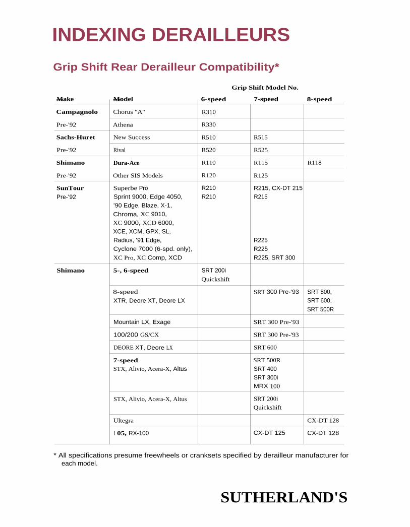
INDEXING DERAILLEURS
Grip Shift Rear Derailleur Compatibility*
Campagnolo Chorus "A" R310
Pre-'92 Athena R330
Sachs-Huret New Success R510 R515
Pre-'92 Rival R520 R525
Shimano Dura-Ace R110 R115 R118
Pre-'92 Other SIS Models R120 R125
SunTour Superbe Pro R210 R215, CX-DT 215
Pre-'92 Sprint 9000, Edge 4050,'90 Edge, Blaze, X-1,
Chroma, XC 9010,XC 9000, XCD 6000,XCE, XCM, GPX, SL,Radius, '91 Edge,Cyclone 7000 (6-spd. only),
XC Pro, XC Comp, XCD
R210 R215
R225R225
R225, SRT 300
Shimano 5-, 6-speed SRT 200i
Quickshift
8-speed
XTR, Deore XT, Deore LXSRT 300 Pre-'93 SRT 800,
SRT 600,
SRT 500R
Mountain LX, Exage SRT 300 Pre-'93
100/200 GS/CX SRT 300 Pre-'93
DEORE XT, Deore LX SRT 600
7-speed SRT 500R
STX, Alivio, Acera-X, Altus SRT 400SRT 300iMRX 100
STX, Alivio, Acera-X, Altus SRT 200i
Quickshift
Ultegra CX-DT 128
1 05, RX-100 CX-DT 125 CX-DT 128
* All specifications presume freewheels or cranksets specified by derailleur manufacturer foreach model.
SUTHERLAND'S
MakeMake, ModelModel
Grip Shift Model No.
6-speed 7-speed 8-speed

INDEXING DERAILLEURS
Grip Shift Front Derailleur Compatibility*
MakeDouble/Triple
Model i ChainringsGrip ShiftModel No.
Campagnolo Chorus, Athena, Croce D'Aune Double F310, F330
Pre-'92
Sachs-Huret New Success Double F510, F515
Pre-'92 Rival Double F520, F525
Shimano Pre '93 Dura-Ace Double F110, F115, F118
Pre-'92 Pre '93 Other Models Double F120, F125
Triple Fl 201, Fl 25T
XTR Triple SRT 500, 600, 800
8-speedDeore XT, Deore LX
TripleTriple
SRT 3001, 400, 500,600, 800
7-speed
STX, Alivio, Acera-X, Altus
TripleTriple
SRT 300i, 400, 600,MRX 100
5-, 6-speed Triple SRT 200i, Quickshift
7-, 8-speed, Ultegra, 105, RX-100 Double CX-DT 118
RX-100, RSX Double CX-DT 118
SunTourPre-'92
Superbe ProSprint 9000
Double F210, F215,CX-DT 215
GPXCyclone 7000 Triple F210T, F215T
XC ProXC CompXCD
.* All specifications presume freewheels or cranksets specified by derailleur manufacturer foreach model.
SUTHERLAND'S

Pro series
model number location
INDEXING DERAILLEURS
Grip Shift Model Identification
Direction of RotationModel Fits Handlebar for Cable-pull*Name Diameter Front Rear Distinguishing Features
Cat-1 1 23.9 - 24.4 mm Counter-
clockwise
Clockwise Knurled plastic, dosed on one end
DB2 (Supplied) Counter-
clockwise
Clockwise Knurled plastic, closed on one end
CX 22.2 - 22.6 mm Clockwise Counter-clockwise
Knurled plastic, open on both ends
Pro-Cat' 23.9 - 24.4 mm Counter-clockwise
Clockwise Foam grip, closed on one end
Pro-CX .22.2 - 22.6 mm 3
or 23.9 - 24.4 mm 3
Counter-clockwise
Clockwise Foam grip, open on both ends
Pro-CX 22.2 - 22.6 mm 4 Counter-clockwise
Clockwise Foam grip, open on both ends
CX -DT 22.2 - 22.6 mm 5 Clockwise Counter-clockwise
Krayton rubber grip, for road bars
SRT 6 22.2 mm Clockwise Counter- Krayton rubber grip, for ATB bars
800 72° clockwise 24 speeds
600 72' 24/21 speeds
400 72° 21 speeds
MRX/100 143° 21 speeds
Quickshift 18/15 speeds
300 143° 21 speeds
200 18/15 speeds
* As viewed from the end of the handlebar.
1 Requires drilling handlebars.
2 Same as Cat-1, except supplied withpre-drilled handlebar.
3 Intended for use with aero bars; comes with a
removable shim to accommodate both sizes.
4 Intended for use with mountain bars; the damp
is designed to provide extra clearance for brake
lever clamps.
$ Comes with collars to fit larger size bars.
6 All are index or friction.
Model number
location
SUTHERLAND'S

GRIP SHIFT PARTS COMPATIBILITY CHART100/150 200/300 200i/300i 400 500/500R 600 800
1. Springs 600-401 500-509 600-401 600-401index rear 500-318 500-318 500-318 600-505
index front 500-319 500-319 (metal upgradefriction front 500-255 500-255 spring)
2. Retention/cable coverfront 500-364 500-505 500-6Q7 500-607rear 500-363 500-505 500-505 500-50
3. Set screw 600-304- 1 600-304- 1 600-304- 1 YT4. Clamp bolt 600-502 600-502 600-502 600-502S. Clamping collar-front 600-601 600-601 600-6016. Clamping collar-rear 600-210 600-210 600-211 600-501 600-501 600-501 600-5017. Nylon washer 500-308 500-308 600-2018. Retention screw 600-302 600-3029. Retention & cable cover-front 500-364 500-407
10. Retention & cable cover-rear 500-363 500-40611. Barrel adjuster 600-308 600-308 500-506 500-506 600-506 500-506 500-50612. Cover screw 600-503 600-503 600-503
13. Rubber seal 500-508 500-508 500-50814. Noodle-front 500-609 500-60915. Noodle-rear 500-507 500-507 500-50716. Fr. housing (no barrel adjust) 500-252 500-25217. R. housing (no barrel adjust) 500-251 500-25118. Front housing 500-2511 500-302 500-362 500-4021 500-502 500-602 500-80219. Rear housing 500-301 500-361 500-401 500-5011 500-601 500-801120. Friction front grip 500-256 500-5266 500-3663 500-405 500-5122 500-605 500-80521. Dual SIS front grip 500-323 500-323 500-3654 500-404 500-513 500-604-1
22. Dual SIS front grip 8-spd 500-517 500-604 500-804-2
23. Shimano 5-spd front grip 500-303-8 500-303-8 500-303-824. Shimano 6-spd rear grip 500-303-7 500-303-7 500-303-725. Shimano 7-spd rear grip 500-303-1 500-303-115 500-403 500-503-5-R 500-603-1226. Shimano 8-spd rear grip 500-503-3-R 500-603 500-803-227. Monster Paw 500-81028. Mini Paw 500-61029. Mud Paw 500-52130. Ribbed grip cover 500-410
Replacement 1.1 cable for 800 SRT (standard was 1.2 cable), some teflon cables do work/Grip Shift is changing cable groove on grip.

GRIPSHIFT PARTS COMPATABILITY CHART (CONT'D)
CX-DT, PRO-CX, PRO-CAT
Slid Stud 600-010Thrust Washer 600-017Crash Shield 500-231Cleat 500-232Back Screw 600-205
.875 Clamping Collar 600-201
.940 Clamping Collar 600-200Set Screw
(9.4mm for .94 clamping collar) 600-012-2(11mm for .875 clamping collar) 600-012-3
Down Tube Adjuster Bracket 600-004
Adjuster Barrel 600-005
Adjuster Barrel Spring 600-006Button Head Screw 600-003Mandrel 500-202
Dura Ace 7/8-spd Grip 118RG07
Ultegra/105 8-spd Rear Grip 128RG0Shimano 7-spd Grip(not DA) 125RG0
Dura Ace Front Grip 118FGO
Ultegra/105 Front Grip 128FG0
Shimano Front Grip(not DA) 125FG0
Suntour 7-spd Rear Grip 215RG0
Suntour Front Grip(not DA) 215FGO
1 Housing assemblies include a clamping collar, clamping bolt and barrel adjuster.
2 Front and rear grips do not include grip covers.3The 300i-11 front grip is interchangeable with 200i-1 1 front grip.
4The 300i-32 front grip is interchangeable with 2001-33 front grip.5The SRT 300i-71 rear grip is interchangeable with a SRT 150-71 rear grip.6 The SRT 150-11 front grip is interchangeable with SRT 100-11 front grip.7CX-DT single shifter assemblies include a complete shifter with a cable and down tube barrel adjuster hardware.

Model
840 (short cage)841 (longcage)845 (ATB)
TotalCapacity
30132T44T
Max.FreewheelTeeth
28T30T32T
INDEXING REAR DERAILLEURS
MAVIC INDEXING
Design Elements• One set of levers (821) is used to index both 6- and 7-speeds. The cable routing
through the derailleur is adjustable for narrow- or regular-spaced freewheels.
• The derailleur guide pulley is a non-floating design and overshift is built into the lever.
Chain RecommendationsUse Sedis ATB, MC-90, MC-55, or MC-50 chain or other high quality bush i ngless chain, (see Sedischain notes on page 6-8 in the Sachs-Huret section when using Sedis chains.)
Freewheel RecommendationsMavic found that Shimano or Aris freewheels work best. Do not use Sun 1 our CS-PF12 and CS-PF22.
MAVIC INDEXING LEVER (821 ROAD)On the derailleur between the cable anchor bolt and the cable adjusting barrel is a small arm
with a hole in it. Route the cable through the hole for regular-spaced freewheels. Route the cablebehind the arm for narrow spacing.
Mavic Indexing Rear Derailleurs
MAVIC ZAP ELECTRONIC INDEXING DERAILLEUR
InstallationFhe 5mm alien hole in the mounting bolt is in the opposite end of the bolt from the usual posi-
tion. Remove the wheel and insert the alien key on the inboard side of the hanger. The indexingadjusting knob is where the mounting bolt head usually is. When installing or removing the
derailleur, loosen the indexing adjusting knob a few turns until the pin that is visible through
the mounting bolt allen hole is either flush with bottom of the hole (for installation) or deeper
(for removal). This insures proper engagement of wrench and bolt so that neither gets stripped.
Adjusting for 7- and 8-speedsTo adjust the derailleur from a 7-speed to an 8-speed (or vice versa), take off the derailleur bodycover by removing the two recessed screws facing outward from the bike (do not remove the two
non-recessed screws facing downwards) and slide the gray body cover off. Rotate the upper pulley
SUTHERLAND'S

INDEXING DERAILLEURS
MAVIC ZAP ELECTRONIC INDEXINGDERAILLEUR (CONT'D)
Adjusting for 7- and 8-speeds (contd)of the derailleur so the flathead screw on the arm is easily accessible. To adjust from 7 to 8 speeds,turn the flathead screw 1/8 turn clockwise. To adjust from 8 speeds to 7, turn the flathead screw 1/8turn counter-clockwise. Replace the plastic gray cover and adjust the derailleur.
Adjusting the IndexingMount the wheel. Extend the derailleur completely by pulling on the jockey wheel. Use theindexing adjusting knob to align the jockey wheel beneath the largest cassette cog.
ShiftingThe in and out position of the two Phillips head screws on the bottom of the derailleur body is
critical. We don't recommend adjusting these screws. However, we learned the following byplaying with them. If all the screws are tightened too far down, the sensory switch may indicate
that the derailleur is between cogs and may shift multiple times. If the screws are marginally too
tight, the derailleur may intermittently mis-shift, usually shifting two cogs at a time. If thescrews are marginally too loose, the derailleur may keep shifting until it reaches the limits of its
travel. if the screws are very loose or missing, the derailleur will not shift at all. Remember toreapply Locktite (blue 242) to the screws.
OtherThe early version of t he microprocessor unit was susceptible to moisture. With all versions of theZAP system, try not to immerse the derailleur or microprocessor unit and make sure that theplug connection on the derailleur is attached firmly and is clean and dry.
Do not attempt to remove the round ("manhole") covers with the six holes in them. Thesehouse the solenoids and sensor switch and are not user serviceable. Removal of the covers or the
upper pulley will void the manufacturer's warranty.
Mavic Non-Indexing Rear Derailleurs
Max.Total Freewheel
Model Capacity Teeth
n 801 36T 32Tn 803 36T 32Tn 851 361 321• 853 36T 32T
SUTHERLAND'S

NON-INDEXING DERAILLEURS
Mavic Front Derailleurs
ModelHalf-Step/Alpine*
Max.ChainwheelDifference
Clamp Diameteror Braze-On (B/O)
• 810 half-step 20T 28.0
• 811 half-step 20T French Style B/0
• 812 half-step 20T Italian Style B/0
• 813 alpine 26T 28.0
• 830 alpine 26T 28.0
• 831 alpine 26T French Style B/0
• 832 alpine 26T Italian Style B/0
• 860 half-step 20T 28.0
• 861 half-step 20T French Style B/0
• 862 half-step 20T Italian Style B/0
• 863 alpine 26T 28.0
• 870 alpine 26T 28.0
• 871 alpine 20T French Style B/0
• 872 alpine 26T Italian Style B/0
• 875 alpine 26T 28.0
(See page 7-10 for half-step/alpine definition.)
Simplex Front Derailleurs
ModelModelNo.
Half-Step/Alpine*
CapacityMin. Max.
Clamp Diameteror Braze-On (B/0)
• SJA 103 MB alpine 24T 28.0-28.6
• SJA 102 half-step 1 4T 28.0-28.6
• SJA 103 alpine 24T 28.0-28.6
• SJA 222 half-step 14T French-style 8/0
• SJA 223 10650 alpine 24T French-style B/0
• SJA 302 1 0535 half-step 1 4T 28.0-28.6
• SJA 303 1 0594 alpine 24T 28.0-28.6
• SLJ A 422 half-step 1 4T French-style B/0
• SLJ A 423 1 0710 alpine 24T French-style B/0
• SLJ A 522 4983 half-step 1 4T 28.0-28.6
• SLJ A 523 4998 alpine 24T 28.0-28.6
• SLJ A 622 1 0785 half-step 1 4T Italian-style B/0
• SX A 32 1 0500 half-step 1 4T 28.0-28.6, 25.4
• SX A 33 1 0510 alpine 24T 28.0-28.6, 25.4
* (See page 7-10 for half-step/alpine definition.)
SUTHERLAND'S

ModelModelNo.
TotalCapacity
• Alpha T/P
• Criterium (withdimpled cage)
• Criterium AR 637 NILJ
• 1000 T• LJ 4000 CP/SPLJ• Super 615
• Maxi (Prestige)• Prestige 637
(see SX 100T)• Prestige AR 637 NI• Prestige AR 637 P
• S 001 T/P• S 061 T/P
• SJ 810 GT/P
• SLJ 5500 CP/SP• SLJ 5500 GT/SP• SLJ 5500 T/SP• SLJ 6600 GT/SP• SLJ 6600 T/SP
• SLJ A 5000 T• SLJ A 5000GT• SLJ AR 615 NI
• SO 1 T/P• SX 1 T/P• SX 100 T 637-P
• SX 400 GT• SX 410 GT/P• SX 410 T/P• SX 440 GT/SP• SX 440 T/SP
• SX 610 GT/P• SX 610 T/P• SX 630 GT/SPMB• SX 630 T/SP• SX 640 GT/SP• SX 640 T/SP
• SX 810 GT• SX 810 T
1 0074
5578
10039
55505554555155525553
1 0043
1 01651 0125
1 02351 0185
30T
301
34T
30T26T30T
39T
34T
34T
30T30T
39T
26T39T
30T
39T22T
30T39T36T
30T30T30T
40T39T
30T
40T
30T
38T28T38T28T38T28T
39T30T
NON-INDEXING DERAILLEURS
Simplex Rear Derailleurs
Max. Freewheel Teeth
24T or 30T (adjusting screw)
30T
34T
30T26T30T
36T
34T34T
30T30T
36T
26T36T30T36T24T
30T36T34T
30T24T or 30T (adjusting screw)30T
36T36T30T34T30T
36T28T34T28T32T28T
36T30T
SUTHERLAND'S

CONTENTS
10
HubsFront hubs ................................... 2
Ball sizes .................................. 2
USA Retainers .............................. 2
Rear hubsMulti-speed freewheel......... 2-3Ball sizes .................................. 2
Front hub and axledimensions ............................ 4
Rear hub dimensionsNational tendencies ............... 5To measure Dimension A ....... 5
Axle spacers ............................ 5
Chainlines .................................... 5
To measure Dimension B ........ 5
Freewheel clearance ................... 6
Rear hub and axledimensions ......................... 6-7
About cartridge bearings ....... 8-9
Sealed cartridge bearings
compatibility .......................... 9
Cartridge-bearing hubsDisassembly .......................... 10Assembly ............................... 1 1
Thread chaser markingsBicycle research ..................... 1 2Quick release skewers .......... 1 2
SUTHERLAND'S

HUBSFRONT HUBS
Ball Sizes•Most front hubs use 10 - 3/. " balls per side except the following:
ACS Pre - 1983 9 - 5/64" balls per sideACS 1983 - current 9 - 1/4" balls per sideCampagnolo 9 - 7/32" balls per side-Nuovo Record, Super Record, Record*
10 - 3/16" balk per side-Grand Sport, Victory, Chorus, Croce D'Aune and othersMaillard Spidel 9 - 7/32" balls per sideNormandy Competition (old style with shallow cut cone) 12 - 3/16" balls per sideSunshine Pro -Am 11 - 3/16" balls per sideSuperbe 11 - 3/16" balls per side
Zeus Gran Sport 9 - 7/32" balls per side
* Record marked S.U. on center of hub shell uses 9 - 7/32".Record not marked S.U. on center of hub shell uses 10 - 3/16". Right-hand hub cones tend to rotate and tighten toward the center, eventually cracking
the hub shell. Tighten the right cone and locknut firmly against each other and make
adjustments on the left side.
When installing Phillips or Raleigh hubs with fixed cones that fit against a shoulder on the axle,he sure that the fixed cone is on the right and the adjusting cone with flats is on the left.
On Schwinn front hubs without cone locknuts, be sure the cone lockwasher is on the right side.
USA RetainersNo. of Balls Diameter
Retainer Per Retainer of Balls Manufacturer
23 8 1/4" Bendix Heavy Duty42 1 0 1/4" Bendix Trailer Hub1 0 5 1/4" Excel' Mark VII5 7 3/16" Excel Mark 6010 5 1/4" Monark Silver King1 3 7 1/4" Musselman5 7 3/16" New Departure3201A 7 Schwinn5 Skived 7 3/16" Schwinn Union5 7 3/16" Schwinn Union4962H . Union Heavy
[13 7 1/4" Westfield
SUTHERLAND'S

HUBS
REAR HUBS – MULTI-SPEED FREEWHEEL
Ball Sizes- 1/4" balk per side except the following:
ACS Pre-1983 9 - 15/64" balls per side
ACS 1983-current 9 - 1/4" balls per side
Maillard Helicomatic 1 3 - 5/32" balls per side
Schwinn Disc Brake 12 - 3/16" balls per side
Suntour Cassette Hubs 12 - 3/16" balls per side
Suntour XCD 1989 9 - 1/4" balls left side, 12 - 3/16" balk right side
SUTHERLAND'S

Front ThreadOver AxleLocknuts Length
HUBSFRONT HUB AND AXLE DIMENSIONSNote: 9.5mm is very close to 3/8". The same is true of 8mm and 5/16".
ISO Solid 8mm x 1mm 1 00 ± 1 mm (primary)
91 ± 1mm (secondary)
ISO Hollow 9mm x 1 mm 100 ± 1mm (primary)
(and BMX solid) 91 ± 1 mm (secondary)
EnglishSolid 5/16" x 26 TPI too many variationsDynohub 3/8" x 26 TPI*
French Most common 5/16" x 26 TPISolid - Rare 8mm x 1 mm 96mm 1 32mm
(or 26 TPI)
Hollow 9mm x 1mm 96mm 105mm(or 26 TPI)
ItalianSolid 8mm x 26 TPI 1 02mm 135mm
Hollow 9mm x 26 TPI 1 02mm 111mm
Japanese'82 SunTour MTB 10mm x 1mm 100mm
Solid - Common road 5/16" x 26 TPI 89, 93mm 130mmCommon off-road 3/8" x 26 TPI* 96mm 1 33mmOff-road SunTour/Shanshin/Specialized 9mm x 1mm (JIS) 1 00mm 1 08mm
Hollow - Rare 9mm x 26 TPI 96mm 104mmCommon 9mm x 1mm (JIS) 100mm 108mm
Shimano, SunTour, Maillard** 9mm x 1mm 100mm 110mm
USASolid - Economy types, 5/16" x 24TPI, too many variations
Quality types 3/8" x 24TPI*
CampagnoloSolid - Nuovo Tipo 8mm x 26 TPI 1 00mm 132mmSolid - Track 9mm x 26 TPI 1 00mm 139mm
Hollow 9mm x 26 TPI 1 00mm 108mm** 9mm x 26 TPI 100mm 110mm
JOU YU (Joy Tech)Solid 8mm x 26 TPI 140mm
Hollow 9mm x 26 TPI 110mm
Ringle (unthreaded) 21.7mm axle 1 07.8mm
BMX–Solid 93, 96mm
Mountain Bike 96, 100mm
* flatted to 5/16"(8mm)
** Wheels Manufacturing , Inc. SUTHERLAND'S

HUBS
REAR HUB DIMENSIONS
National TendenciesThere are many exceptions, so measure if in doubt. Make up for differences by adding, remov-ing, or relocating washers and spacers. if axle length won't allow the change, squeeze or spread
the drop-outs. Align the drop-outs with the proper tool after altering the width. Never use the
action of a quick release unit to squeeze the drop-outs together.
To Measure Dimension AHold a piece of square bar (a square-shank screw-driver for approximate measure) against the lock-
nut and axle so that it's perpendicular to the axle,then measure the distance between the side the
freewheel butts against and the bar.
Axle SpacersAxle spacers arc available I rom a number of sources.
CHAINLINESFront chainline refers to the distance from the bicycle centerline to chainring midpoint. Rear
chainline is the bicycle centerline to sprocket midpoint. Front and rear chainlines rarely matchin practice. Chainrings are frequently moved out to avoid having the chain rub on the outsidechainring when the gears are in a small chainring and small sprocket combination. Also, some-
ti mes the frame will he built with the right drop-out extending out further than the left.
To Measure Dimension BRear chainline is easily determined by measuring the distance from the drive side locknut to thesprocket midpoint and subtracting that dimension from haf the overlocknut dimension. Thismethod will not work with offset rear triangles, but those are not common.
Front chainline is determined by measuring the distance from the seat tube to the chainring mid-point and adding the half the diameter of the seat tube. Generally, bikes with a single chainringhave a 40 to 42.2mm front chainline. Bikes with double chain rings have a 43.5 to 45.5mm front
chainline. Bikes with triple chain rings have 47 to 50mm front chainline.
SUTHERLAND'S

Over Axle Dimen- Dimen-Locknuts Length sion A sion BThreadRear
HUBS
FREEWHEEL CLEARANCEFreewheel Width(Sprocket Face toSprocket Face)
MinimumDimension A
Regular Spacing5 speeds 25 296 speeds 31 35
Narrow Spacing6 speeds 27 317 speeds 32 368 speeds 36.5 40.5
Frames whose right stays have flattened ends must be used with Campagnolo and other similar hubs
wit h a minimum Dimension A. This is so the chain clears easily and the wheel can be removed.
REAR HUB AND AXLE DIMENSIONS
ISO
Solid 9mm x 1 mm
Hollow 1 0mm x 1mm
Single freewheel, 110mm 21mm
Coaster brake
3-, 4-speed freewheel, 117mm 28mm
Hub gear
4-, 5-speed freewheel 122mm 34mm
5-, 7-speed freewheel 126mm 36mm
ENGLISH—Solid 3/8" x 26 TPI many variations
FRENCH
Solid - Rare 9.5mm x 1 mm 122mm 1 60mm 34mm
Rare (or 26 TPI) 124mm 1 62mm 36mm
126mm 1 65mm 36mm
Common 3/8" x 26 TPI 130mm 1 68mm 36mm
Hollow - Rare 9.5mm x lmm 122mm 1 33mm 34mm 39.5mm
Rare (or 26 TPI) 1 24mm 135mm 36mm 40mm
Common 1 0mm x 1mm 126mm 137mm 36mm varies
Maillard 700 1 0mm x .75mm 1 30mm 140mm 36mm varies
ITALIAN
Solid 9.5mm x 26 TPI 122mm 155mm 34mm
Hollow 9.5mm x 26 TPI 122mm 1 32mm 34mm
1 26mm* 136mm 36mm*
* Before ISO standards were adopted, many were 125mm with 35mm freewheel space.
SUTHERLAND'S

HUBS
REAR HUB AND AXLE DIMENSIONS (CONT'D )
Rear ThreadOver Axle Dimen- DimenLocknuts Length sion A sion B
J APANESE
Coaster 3/8" x 26 TPI
Solid - Common 3/8" x 26 TPI, 124mm* 1 69mm 36mm* 43.5mm
SunTour/Sanshin/ 10rnmxlmm(JlS) 1 26mm 1 69mm 36mm varies
Specialized 1 30mm 1 75mm 37mm varies
Hollow - Rare
Common
3/8" x 26 TPI,
10mm x 1 mm (J15)
1120mm 128mm 1
124mm 1 32mm I
31mm
34mm
42mm
1 26mm* 136mm 36mm*t 43.5mm
1 30mm 140mm 37mm 43.5-45mm
1 35mm 1 45mm varies 45-47.5mm
S SA—Solid - Coaster/BMX 3/8" x 24TPI
BMX 1 09mm 21mm
110mm
MOUNTAIN BIKE 1 26mm 37mm
130mm 37mm
135mm 42mm
CAMPAGNOLO
Solid - Nuovo Tipo - Rare 9.5mm x 26 TPI 120mm 155mm 29mm
Solid -Track 1 0mm x 26 TPI 110mm 149mm 21.5mm 40mm
120mm 159mm 24mm 42.5mm
Hollow 10mm x 26 TPI 1 21 mm** , 129,132mm 30mm" 43.5mm
125mm 1 34mm 35mm 43.5mm
126mm 1 36mm 36mm 43.5mm
130mm j 140mm 36,37mm 43.5-47.25mm
JOU YU (Joy Tech)Solid
Hollow
CRONOMETRO - cartridge axle
9.5mm x 26 TPI10mm x 26 TPI
20.6mm x sealed
* Before 150 standards were adopted, many were 125mm with 35mm freewheel space.
t These hubs may also come with a 31 or 33mm Dimension A to accommodate derailleurs
( mostly higher priced) that will not sweep the 36mm.
" This hub is often listed as 120 over the locknuts with a 29mm Dimension A.
*** For use in EFC Manitou Fork only.
SUTHERLAND'S

HUBSABOUT CARTRIDGE BEARINGSCartridge bearings are used extensively in the bicycle industry and it would seem logical to justpop a standard bearing in a bicycle hub to get the advantage of its seal. Unfortunately, thesebearings are designed to be mounted with more precision than can be achieved in a convention-
al huh. For long bearing Iife, the inner and outer bearing races must he aligned precisely and stayaligned. Flexing or bending under a load makes this impossible with the 8 to 10mm huh axles
used on many standard hubs. Except in extremely muddy conditions, this misalignment resultsin bearing life even shorter than that of unmaintained cup and cone bearings.
Figure A shows a bearing mounted in a bicycle hub. Note that the load pushes down in the cen-ter of the raceways and there is a slight gap at the top, exaggerated for clarity in the drawing.
[his gap is essential if the bearing is to function smoothly; it can be felt at the rim of a built-upwheel as a trace of side-play. Trying to eliminate this side-play by pushing one of the bearing
raceways to the side will ruin the bearing quickly, (see figure B). Flexing and bending can bereduced by using a large diameter axle, (see Cartridge and Sealed bearings, on page 0-10).
Figure A. Properly Aligned Cartridge Bearing Figure B. Misaligned Cartridge Bearing
To work effectively, the outer raceway must be pressed securely into the huh shell and the inner
raceway must he held securely between shoulders on the axle and tightened locknuts. At the
same time, the inner and outer raceways must be aligned so that the balls run in the center ofthe raceways. Always use an exact replacement axle since an axle with shoulders too far apart ortoo close together will accelerate hearing wear, (see figure B). All parts must be clean so that
debris does not cause misalignment of the raceways.
SUTHERLAND'S

HUBS
ABOUT CARTRIDGE BEARINGS (CONTD)Axles must be straight to keep the inner raceways properly aligned. A bent axle will cause rapid
wear. Tightening a huh with a straight axle into fork ends that are not aligned, (see page 0-10),will bend the axle enough to cause misalignment of t he raceways.
Most cartridge hearings are marked with SKF numbers. All the bearings we measured were metricexcept Cook Bros., which were inch sizes and therefore not interchangeable with the others.
The markings usually consist of a brand name and a number followed by letters. Some common
brand markings are NTN, WTW, NACHI, and KSK. The numbers indicate the standard size. The
letters following the number indicate the type of seal used. Seals are not standard.
The following sizes are common:
Inside Outside Inside OutsideNumber Diameter Diameter Number Diameter Diameter
6000 10mm 26mm 6200 1 0m m 30mm6001 12mm 28mm 6201 12mm 32mm6002 15mm 32mm 6202 15mm 35mm6003 17mm 35mm 6203 17mm 40mm
SEALED CARTRIDGE BEARINGS COMPATIBILITYCompiled by Wheels Manufacturing. Used with permission.
Bearing No. Compatibility ID OD Width
6901 2rs White Industries rear cassette, front 12mm 24mm 6mm
6001 215 American Classic, Kingsbery, Avocet front,Bullseye, Machine Tech, Mavic, Phil Wood,most Ringle, Sansin, Specialized, SunTour,Vertical Dexcent, T-Gear, WTB
12mm 28mm 8mm
6000 2rs Hugi, Pulstar rear, Ringle Freewheel (non-drive side), Sachs, Suzue front, GT front,Perrigrine front, Hope, Joy Tech front sealed,Performance, Sovos front sealed
10mm 26mm 8mm
6200 2rs Suzue rear, Joy Tech rear sealed, Sunshine rear,GT rear, Minoura trainers, Perrigrine rear,Sovos rear sealed
1 0mm 30mm 9mm
99 2rs Zipp, Hershey racing, Nuke Proof, SR sealed,Old GT, DK Products
9.5mm 22mm 7mm
6902 2rs Dia Compe front, Sansin cassette rear,Sansin front, SunTour Microlite,Phil Wood rear and front suspension,White Industries freewheel
15mm 28mm 7mm
6903 2rs TNT front suspension 1 7mm 30mm 7mm
SUTHERLAND'S

Figure C. Removing bearings from hubswith shoulders on the axle.
HUBSCARTRIDGE-BEARING HUBS (EXCEPT PHIL*)-DISASSEMBLY AND ASSEMBLY
1 DISASSEMBLYBe sure you want to replace the bearings, asremoval will ruin good hearings. Note thearrangement of the locknuts and washers so they
can be replaced in the same order. Note alsowhether the unthreaded portion of the axleextends past the cartridge. Remove the locknutsfrom both sides of the huh.
2 DISASSEMBLYFor hubs with shoulders on the axlesUsing soft jaws, support the huh shell (hut not
the hearing or axle) between the open jaws of a
vice. (See figure C.) Thread an axle nut on theaxle to protect the threads. Gently tap on theend of the axle with a rubber mallet until thecartridge on the opposite side comes loose, (asshown in figure C).
For hubs without shoulders on the axles
Remove axle. Squeeze the ends of a SunTourhearing remover together and insert it through
the hole in the inner raceway of the bearing.Insert an old axle in the other side of the hub.Gently tap on the end of the axle with a softhammer until the cartridge on the opposite side
comes loose.
3 DISASSEMBLYRemove the loose cartridge bearing. Repeat to remove the remaining cartridge.
• For Phil hubs, replace the axle and hearings as a unit using the kit and instructions suppliedby Phil Wood and Co.
SUTHERLAND'S

cartridge bearing
—axle nut
cartridge bearing installation washer
HUBS
CARTRIDGE-BEARING HUBS (EXCEPT PHIL*)-DISASSEMBLY AND ASSEMBLY (CONT'D)
1 ASSEMBLY
Figure D. Use of cartridge-bearing installation washers
Hammering on cartridge bearings will ruin them. Insert the axle in the hub. Place one cartridge
on each side. Then place a dished cartridge-bearing installation washer on each end, (see figure D).Be sure to use a washer of proper size that contacts the outer race only. Applying force on theinner race will damage the bearing. If an unthreaded portion of the axle extends past the car-
tridge, additional washers or spacers may be necessary. If used, they should slip freely over theunthreaded portion of the axle. Hand-tighten axle nuts on each end of the axle and align the
installation washers over the cartridges.
2 ASSEMBLYHold the assembly in a vise by one of the axle nuts. Tighten the other axle nut to squeeze the
cartridges into place. Observe progress closely, making sure the cartridges go in straight.
3 ASSEMBLYFor hubs with shoulders on the axles
Loosen one axle nut and add an extra axle nut to it. Lock them together. Working against the
two locked-together nuts, loosen the nut on the other end. Then unlock and remove the remain-
ing two nuts. Remove the installation washers and replace the various locknuts and washers intheir original order.
For hubs without shoulders on the axles
Loosen and remove the axle nuts. Remove the installation washers and replace the various lock-
nuts and washers in their original order.
" For Phil hubs, replace the axle and bearings as a unit using the kit and instructions supplied
by Phil Wood and Co.
SUTHERLAND'S

HUBSTHREAD CHASER MARKINGS
Bicycle ResearchType Size Marking Notes
TC-1 8mm x 26 TPI small (1 /2") hex, no groove
TC-2 9.5mm x 26 TPI large (9/16") hex, no groove
TC-3 5/16" x 24 TPI small (1/2") hex, 1 groove Also fits X caliber skateboard trucks
TC-4 3/8" x 24 TPI large (9/16") hex, 1 groove
TC-5 5/16" x 26 TPI small (1/2") hex, 2 grooves
TC-6 7.5mm small (1/2") hex, 3 grooves Fits Chicago skateboard trucks
TC-7 3/8" x 26 TPI large (9/16") hex, 2 grooves Many BMX, some skates
Quick Release Skewers
Model OD Pitch
Atom 5mm x 0.90mm
Brev. Stop 5mm x 0.80mm
Campagnolo 5mm x 0.80mm
Gnutti 5mm x 0.80mm
Milremo 5mm x 0.90mm
Normandy 5mm x 0.90mm
Pelissier 5mm x 0.90mm
Schwinn Approved(made in France) 5mm x 0.90mm
Shimano 5mmx 0.80m m
Simplex Old Style* 5mm x 0.75mm
Simplex New Style* 5mm x 0.80mm
SuspensionFront 9mm x 25 TPIRear 10mm x 25 TPI
Weyless .25" x 28 TPI
Zeus 5mm x 0.80mm
* Simplex Old Style has plastic wing nut; Simplex New Style is all metal.
SUTHERLAND'S

CONTENTS
About Spoke LengthsList of hub models ...................... 2
About theSpoke Length Charts .............. 3Heavy gauge spokes ............... 3Straight-pull spokes ................ 3
Large flange hubs ....................... 3
Radial patterns ............................ 4
Spoke and nipple
dimensions ............................ 5
Calculating rim correctionfactors ................................ 1 08
Number of spokes ................. 1 09
Calculating Spoke LengthStep 1: Hub FlangeHub flange diameter ................. 6
Electronic calculations ............... 6
31mm diameter .................... 7-8
34mm diameter .................... 8-9
40mm diameter ................ 1 0-15
44.5mm diameter ........... 15-22
48mm diameter ................ 23-27
58mm diameter ................ 27-28
63mm diameter ................ 29-30
67mm diameter ................ 31-34
90mm diameter ................ 34-35
102.5mm diameter ............... 35
Huh additions .................... 36a-e
Calculating Spoke LengthStep 2: Spoke Charts27" .............................................. 37
700C .......................................... 45
26" .............................................. 61
24" .............................................. 81
22" .............................................. 81
20" ......................................... 92
18" .............................................. 99
17" .............................................. 99
1 6" ........................................... 101
14" ........................................... 104
12" ........................................... 1 06
10" ........................................... 107
Calculating Spoke LengthStep 3: Rim Correction27" ..............................................40
addition 8/95 .................... 44a
700C .......................................... 48additions 8/95 ............... 60a-h
26" .............................................. 64
additions 8/95 ........... 70a,80a
24" .............................................. 84
22" ......................................... 84
20 " ..............................................94
18"' ........................................... 100
1 7" ........................................... 100
1 6" ........................................... 102
1 4" ......................................... 105
1 2" ........................................... 106
10" ....................................... 107
24" & below additions ........ 110a
SUTHERLAND'S

SPOKE LENGTHS
I NDEX OF HUB MODELS31mm
34mmClark Kent ............................ 8Excel ..................................... 8Hershey .............................. 8Union/Hope ....................... 8King Kong/KK ..................... 8Maillard .............................. 8Mavic ................................... 9Normandy ......................... 9Nuke Proof ..................... 36aPhil Wood ............................ 9Shimano .............................. 9Sturmey Archer .................. 9SunTour .............................. 9TNT ..................................... 9Ulterrain .............................. 9Union .................................. 9Wald ..................................... 9White ................................... 9
40mmAmerican Classic .............. 10Answer ............................ 36aArai ..................................... 10Ariel ................................... 10Bici ..................................... 10Campagnolo ..................... 10Clark Kent ......................... 10Coda ................................ 10Cunnane ............................ 10DK ..................................... 10Diacompe ......................... 10Elf ....................................... 11Falcon .............................. 36aGT ..................................... 11Hershey ............................ 11Hi-E ................................... 11Union/Hugi ....................... 11Joy Tech ............................ 11Justin ................................ 11KT ....................................... 11King ................................ 36aMaillard ............................ 11
Mavic.................................. 11Miche ................................ 11
Revcore .............................. 12Rhino ................................ 12Ringle ................................ 12Sachs ................................ 12Sampson ............................ 12Sansin ................................ 12Selkirk ................................ 12Shimano .............. 12-13,36bSovos ................................ 13Specialized ....................... 13Stronglight ....................... 13
SunTour ............................ 13Suzue ................................ 14TNT ................................... 14T-Gear .............................. 14Trek ................................ 36bUltimate ............................ 14Union/Hope .................. 36bWCW ................................ 1 4Wheelsmith ..................... 14White ................................ 14Wilderness Trail Bikes. 14,36bZipp ................................. 36b
44.5mmA/C ..................................... 1 5ACS ................................... 15A R R ................................... 15American Classic 15,36cAriel ................................... 15Atom ................................ 15Bici ..................................... 15Bullseye ............................ 16Campagnolo ..................... 16Coda ................................ 36cDK ..................................... 17Diacompe ......................... 17Elf ....................................... 17Falcon .............................. 36cGT ..................................... 17Gila .................................. 36cHershey ............................ 17Hooker .............................. 17Union/Hope ..................... 17Union/Hugi ....................... 17
joy Tech ............................ 17
Kingsbery ......................... 17
King Kong/KK .................. 17
KT ....................................... 18Machine Tech ..... 18 36cMaillard ............................ 18Mavic ................................ 18Mountain Cycle .............. 36cNosier ................................ 18Nuke Proof ....................... 18Primo .............................. 36cProfile ................................ 18Redline .............................. 18Rhino ................................ 18Ringle ................................ 19Sachs ................................ 19Sampson ............................ 19Selkirk ................................ 19Shimano .............. 19-21,36cSovos ................................ 21Specialized ....................... 21Stronglight ....................... 21SunTour ............................ 21Suzue ................................ 22T-Gear .............................. 22TNT ............................ 22,36cUnion .............................. 36cWheelsmith ..................... 22White ................................ 22Zipp ............................ 22,36c
48mmBendix .............................. 23Clark Kent ......................... 23Cook Bros. ....................... 23Diacompe ......................... 23Falcon .............................. 36dGT ..................................... 23Hershey ............................ 23King Kong/KK .................. 23Mavic ................................ 23Miche ................................ 23Nuke Proof ....................... 23Phil Wood ................... 23-26Pulstar .............................. 26Revcore .............................. 26Sachs ................................ 26Sansin ................................ 26Shimano ............................ 26Specialized ....................... 26Sturmey Archer ................ 26Sunshine ............................ 26SunTour ............................ 27Union .............................. 36d
WCW ................................ 27
58mmBullseye ............................ 27Union/Hugi ....................... 27Hyper .............................. 36dPhil Wood ................... 27-28Sachs ................................ 28Shimano ............................ 28Sturmey Archer .... 28,36dWhite ................................ 28Wilderness Trail Bikes . . . . 28
63mmACS ................................... 29GT ..................................... 29Joy Tech ............................ 29King Kong/KT .................. 29Maillard ............................ 29Normandy ....................... 29Peregrine ......................... 29PMC ................................... 29Sansin ................................ 29Shimano ............................ 29Sunshine ............................ 29SunTour ............................ 29Suzue ................................ 30
67mmCampagnolo ..................... 31Hi-E .................................. 31Phil Wood ................... 31-33Sachs ................................ 33Sansin ................................ 33Shimano ............................ 33Sturmey Archer ................ 33SunTour -................... 34
90mmBendix ............................ 34Sachs ....................... 34-35Shimano ....................... 36eSturmey Archer ..... 35WestPine .................... 36e
102mmSturmey Archer ..... 35Westpine .................... 36e
American Classic ................ 7 Nuke Proof ................ 11,36aHershey .............................. 7 Odessey ............................ 11Union/Hope ....................... 7 Phil Wood ......................... 11Nosier ................................... 7 Primo .............................. 36aNuke Proof ......................... 7 Profile ................................ 11TNT ..................................... 8 Pulstar .............................. 11Ultimate .............................. 8 Redline .............................. 12
SUTHERLAND'S

Spokes are
measured
from the
inside of
the bend
to the
end.
Straight
pull
spokes are
measured
from the
base of the
head to
the end.
SPOKE LENGTHS
ABOUT THE SPOKE LENGTH CHARTSUsing the tables in this chapter will give you spoke lengths that are accurate to within + or - 1.5
mm. This is as accurate as is needed for most wheels. For wheels that are smaller than 20", manymore factors come into play, and these tables will he less accurate and should only be considered as
a starting point for sonic trial-and-error wheel building. When more accuracy is needed or when
spoke lengths are needed that are not listed here, we recommend using the Spoke Master programthat is part of Bike`alog or the Wheelsmith Spoke Calculator. We have listed rim and hub dimen-
sions for the Wheelsmith and other computer programs in separate shaded columns. When usingthe Wheelsmith calculator or other programs, you will only need to use the tables in steps 1 and 3.
Spoke and Nipple DifferencesSpoke lengths are calculated to come to the bottom ofthe slot of a Union, DT, or Wheelsmith spoke nipple.
Measure the spokes you use; compare your measurement
with the measurement printed on the box they came in.You may need to make your own adjustments to thefinal lengths to get more consistently accurate results.
Hub Spoke Holes and SpokeDiameterHeavy gauge spokes combined with large hub
spoke holes generally use the same lengths as normal
size spokes. The effect of the larger hole is cancelled
out by the larger nipple used. To use a regular gaugespoke in a larger hub hole will require a shorter spoke.The amount the spoke is shorter is usually small (lessthan 0.5mm) but can combine with other factors to
result in a spoke that is too long.
Straight-pull spokes are used with hubs specifi-
cally designed for them. Instead of having spoke holes that are parallel to the axle
like normal hubs, the spoke holes point towards the rim. The position of the
spoke holes and the angle of the holes drilled into the hub to accommodate thespokes determines the lacing pattern for the wheel. Due to these factors, eachstraight-pull hub has only one lacing pattern that can be used.
LARGE FLANGE HUBSWhen building wheels with large flange hubs, check the angle the nipple enters the rim.Breakage will occur if the spoke nipple is stressed at this point. Rims are sometimes dimpled tomake up for this. Some nipples will work at a bigger angle from perpendicular than others. Try itin a spoke hole to see. Problems usually occur when using drum brakes or other extra largeflange hubs and a 3- or 4-cross pattern. Other problems arise when combining a large flange hub
with a 20- or 24-inch rim. The solution is to use a 2- or 1-cross pattern.
SUTHERLAND'S

SPOKE LENGTHS
RADIAL PATTERNSThe spoke length tables work most easily with tangent or close-to-tangent spoke patterns like 4-
or 3-cross. (See drawings below.) The fewer crosses the wheel is built with, the more exactlythe hub diameter has to match the huh diameter categories in Step 1. Radially built wheels must
match the diameter category exactly for accurate results. For radial wheels, note the differencebetween the hub diameter category listed and the actual huh diameter. Subtract or add 1 mm
from the final spoke length for every 2mm difference.
Note: Many hubs are not sufficiently reinforced for radial spoking (not enough metal around flange).
EXAMPLE: Radial spoking pattem with Phil hubs. Phil all-alloy front hub has a 42mm flange diam-
eter (spoke hole center to spoke hole center). This is 2.5mm smaller than the 44.5mm category.Since the hub is 2.5mm smaller, add 1.25mm to the final spoke length to get an accurate lengthfor a radial wheel. In practice, adding 1 mm is accurate enough.
Rim
Radial spoke
Tangential spokes-like a 4-cross/
36 spoke pattern.
Spokes at a tangent to thehub are nearly identical in
length; hub diameter isnot important.
the hub diameter makes anmportant difference in spokeength with a radial wheel —5mm in this illustration.
48mm hub (to spoke hole centers)
58mm hub (to spoke hole centers)
SUTHERLAND'S

SPOKE LENGTHS
SPOKE AND NIPPLE DIMENSIONSWire diameter below refers to the diameter before the threads are rolled on. The major
0 diameter usually referred to, in thread sizes, will be larger than the wire diameter.
Sizes listed in the same column are roughly the same size.
ISO
Wire Diameter (mm) x TPI 1.5* 1.8 x 56 2.0 x 56 2.3 x 56 2.6 x 56Wire Diameter (inches) x TPI .059* .071 x 56 .079 x 56 .091 x 56 .102 x 56Nipple Flats (mm) 3.3 3.3 3.8 4.5Nipple Diameter (mm) 4.0 4.0 4.5 5.5
English
Gauge (SWG) 1 7* 1 6* 1 5 1 4 13 12Wire Diameter (inches) x TPI .056* .064* .072 x 56 .080 x 56 .092 x 56 .104 x 56
French
Gauge (JP) 1 0* 11* 1 2 13 14 1 5 1 6Wire Diameter (mm)
x mm per thread 1.5* 1.6* 1.8 x .4 2x.4 2.2x.45 2.4 x .45 2.7 x .55Wire Diameter (inches) x TPI .059* .063* .071 x 63.5 .079 x 63.5 .087 x 56.4 .094 x 56.4 .106 x 46.2Nipple Flats (mm) 3.2 3.2 3.2 3.7 4.0Nipple Diameter (mm) 4.0 4.0 4.0 4.5 5.0
(Japanese)
Gauge (for reference only) 15 14 13 12Wire Diameter (mm) x TPI 1.86 x 56 2.0 x 56 2.3 x 56** 2.6 x 56Nipple Flats (mm) 3.4 3.4 3.6 3.9Nipple Diameter (mm) 4.0 4.0 4.3 4.6
USA
Gauge (US Steel Wire Gauge) 1 5 1 4 1 3 12Wire Diameter x TPI .072* .080 x 56 .092* .106 x 56Nipple Flats (mm) 3.3 3.9Nipple Diameter (mm) 3.7 4.57
* These measurements are for the narrower butted portion of the spoke where there are no threads.
** Wire diameter may be 2.3mm. This can then be swaged down to 2.0mm x 56TPI at the threadswith a corresponding shrink in nipple flats and diameter.
Notice that as the wire gets larger, French gauge numbers go up while English and USA gaugenumbers go down. The gauge numbers cross right where cycle spokes are. This is one reason theISO standards for spokes are being adopted all over the world.
To distinguish a spoke with a 56 TPI thread, a 28 TPI thread gauge may be used. It will fit nicelyin every other thread.
SUTHERLAND'S

Hub flange diametersare measured fromspoke hole centerto spoke hole center.
2nd Step27'' ri ms, go to page 11 - 38
700C ri ms, go to page 11 -46
26", 700D and 650 ri ms, go to page 11 - 62
24", 22", 600 and 550 rims, go to page 11 - 74
20" ri ms, go to page 11 -82
16" ri ms, go to page 11 -92
400 rims, go to page 11 - 101
14" ri ms, go to page 11 - 104
12" ri ms, go to page 11 - 106
10" ri ms, go to page 11 - 107
SPOKE LENGTHS
CALCULATING SPOKE LENGTH
1st Step of 3 steps:Determine which hub flange diameter category
the hub fits into.
Sample hubs are listed for each category. Be
sure to measure since there are many models
than are listed here.
Example One: Shimano Dura-Ace smallflange front measures 38mm. It fits the40mm hub flange diameter category.Adjustments will be made in the next step,if necessary.
Example Two: Mavic 500 small flange rearis 44.8mm so it fits in the 44.5mm hubdiameter category.
HUB FLANGE DIAMETER Flange DiameterCategories
31mm ........ from 30mm - 32mm
34mm ........ from 33mm - 36mm
40mm ........ from 37mm - 42mm
44.5mm .... from 43mm -46mm
48mm ........ from 47mm - 52mm
58mm ........ from 53mm - 60mm
63mm ........ from 61mm - 64mm
67mm ........ from 65mm - 69mm
90mm ........ from 80mm - 90mm
102.5mm . from 102.5mm - 112mm
ELECTRONIC CALCULATIONSThe information in the shaded area of the charts to the right of the flange diameter column is
for use with electronic spoke calculators or computer programs. It is also useful for making
adjustments to spoke lengths for unusual hubs.
When using an electronic spoke-length calculator such as Wheelsmith's or a computer program,
you will need only the information in steps i and 3.
SUTHERLAND'S

REAR HUBLEFT AND RIGHT MEASUREMENTS
Left Right(L) hub (R) hubcenter center
to flange to flangecenter
I center
— Over locknuts
Left (L)locknutto flangecenter
Right (R)locknut
to flangecenter
SPOKE LENGTHS
CALCULATING SPOKE LENGTH
1 st Step (contd)
FRONT HUB MEASUREMENT
31 mm FLANGE DIAMETER (30mm - 32mm)Generally: small flange front hubs
Front/Make Model Rear
FlangeDiameter
HubCenter-FlangeCenter
OverLock-nuts
Locknuts-FlangeCenter
AMERICAN CLASSIC
Speedster Time Trial front 30 24 1 00 26
HERSHEY Naked Lexan front 31.7 30 100 20
UNION/HOPE ADVANCED SYSTEM
Super Ultralight front 25.5 35 1 00 15
NOSLER TI-90 front 31.3 36 100 14
Flip-Flop rear * L-31.3 R-43.7 L-47 R-18 130 L-18 R-47
MTB Flip-Flop rear * L-31.3 R-43.7 L-44 R-21 135 L-24 R-47
Stiffy suspension front 31.3 36 1 00 14
TI-90 (not Flip-Flop) rear * L-31.3 R-45.4 L-44 R-19 130 L-21 R-46
(not Flip-Flop) rear * L-31.3 R-45.4 L-45 R-21 135 L-23 R-47
NUKE PROOF XT-Pre '94 sealed front 31.5 37 1 00 13
XT-Pre '94 sealed rear * L-31 R-43 L-45 R-17 1 26 L-18 R-46
rear * L-31 R-43 L-43 R-19 130 L-22 R-46
rear * L-31 R-43 L-41 R-23 1 35 L-27 R-45
MPS-1 front 32 . 37 1 00 13
XT cassette rear * L-32 R-47.3 L-40 R-25 135 L-28 R-43
XTR cassette rear * L-32 R-47.3 L-38 R-22 135 L-30 R-46
XTR cassette rear * L-32 R-47.3 L-38 R-20 130 L-27 R-45
SUTHERLAND'S

SPOKE LENGTHS
31 mm FLANGE DIAMETER (30mm - 32mm)Generally: small flange front hubs
Make ModelFront/Rear
FlangeDiameter
HubCenter—FlangeCenter
OverLock-nuts
Locknuts-FlangeCenter
TNT Road front 31.7 37 1 00 1 3
Road rear * L-31.8R-45.3 L-35 R-19 130 L-30 R-46
Mtn. rear * L-31.8R-45.3 L-33 R-22 1 36 L-35 R-46
Suspension front 41.7 39 1 00 11
8spd rear * L-32 R-42 L-34 R-23 1 30 L-31 R-42
8spd rear * L-32 R-42 L-35 R-22 135 L-33 R-46
7-11 1 8spd rear * L-32 R-42 L-39 R-18 130 L-26 R-47
8spd rear * L-32 R-42 L-39 R-18 135 L-29 R-50
7spd rear * L-32 R-42 L-35 R-22 130 L-30 R-43
7spd rear * L-32 R-42 L-35 R-22 135 L-33 R-46
ULTIMATE standard front 32 32 100 1 8
cassette 7spd rear * L-31.7R-41.4 L-36 R-19 135 L-32 R-49
cassette 8spd rear * L-31.7R-41.4 1-33 R-21 136 L-35 R-47
31mm footnotes* See Spoke Length chart for 40mm, 44.5mm, 48mm Flange Diameter for large flange side of hub.
1 7-speed cassette with added 11-tooth cog.
34MM FLANGE DIAMETER (33mm - 36mm)Generally: fair to good quality small flange front hubs
Make ModelFront/Rear
FlangeDiameter
HubCenter—FlangeCenter
OverLock-nuts
FlangeCenter
Locknuts-
CLARK KENT rear *L - 36.3 R-47.6 L-34 R-23 135 L-34 R-45
EXCEL XLB4290 steel front 34 36 89 9
HERSHEY Naked Lexan front 31.7 30 1 00 20
UNION/HOPE ADVANCED SYSTEM
Ultralight front 34 34 100 16
KING KONG
KK H-480960 steel-5/16 front 34 34 1 00 16
H-480961 steel-28H front 34 35 1 00 15
MAILLARD Sealed Mechanism front 34 35 97 1 3
SUTHERLAND'S

SPOKE LENGTHS
34mm FLANGE DIAMETER (33mm - 36mm)Generally: fair to good quality small flange front hubs
Make ModelFront/Rear
HubCenter-
Flange FlangeDiameter Center
OverLock-nuts
Locknuts-FlangeCenter
MAVIC front 34 28 80 1 2CX 580 front 34 28 81 12
NORMANDY Low Flange B.0. 3 front 34 35 96 13
PHIL WheelchairDinky front 35 22Straddle Mount Dinky front 35 23 63 9
SHIMANO HB-SN11 steel front 35 32 93 15
STURMEY ARCHER front 33 33 88 11
SUNTOUR XCD-6000 front 36 3 100 17
TNT 8spd rear * L-32 R-42 L-34 R-23 130 L-31 R-428spd rear * L-32 R-42 L-35 R-22 135 L-33 R-46
7-11 1 8spd rear *L-32 R-42 L-39 R-18 130 L-26 R-478spd rear *L-32 R-42 L-39 R-18 135 L-29 R-50
7spd rear * L-32 R-42 L-35 R-22 130 L-30 R-437spd rear * L-32 R-42 L-35 R-22 135 L-33 R-46
ULTERRAIN 2 Road front 35 35 1 00 15
7spd rear 35 L-37 R-16 130 L-28 R-498spd rear 35 L-37 R-16 130 L-28 R-49
Mtn. suspension front 35 35 100 157spd rear 35 L-34 R-19 135 L-34 R-49
8spd rear 35 L-34 R-19 135 L-34 R-49
UNION steel front 34 36 100 14
WALD Low Flange B.0. 3 front 333 37 102 14
WHITE TI front 3435
35 100. 15
34mm footnotes
* See Spoke Length chart for 40mm Flange Diameter for large flange side of hub.
1 7-speed cassette with added 11-tooth cog.
2 Use 2-cross for all.
3 Bolt-on.
SUTHERLAND'S

SPOKE LENGTHS
40mm FLANGE DIAMETER (37mm - 42mm)Generally: good to high quality small flange front hubs
Front/Make Model Rear
FlangeDiameter
HubCenter-FlangeCenter
OverLock-nuts
Locknuts-FlangeCenter
AMERICAN CLASSIC
Standard front 42 35 1 02 16
ARAI 8000 front 40 32 82 9
ARIEL ATB front 40 38 1 00 1 2
BICI MTB front 40 36 100 1 4
CAMPAGNOLO
OLD Super Record front 38.5 34 100 16
Nuovo Record front 38.5 34 1 00 1 6
Gran Sport front 38.5 34 1 00 1 6
Victory front 38.5 34 1 00 1 6
Triomphe front 38.5 34 1 00 1 6
NEW C-Record front 38.5 34 1 00 1 6
Chorus front 38.5 34 100 1 6
Athena front 38.5 34 1 00 16
Xenon front 38.5 34 1 00 1 6
Veloce front 38.5 34 1 00 1 6
Mirage front 38.5 34 1 00 1 6
Stratos front 38.5 34 1 00 1 6
Record O.R. front 38.5 34 1 00 1 6
Icarus front 38.5 34 1 00 1 6
Euclid front 38.5 34 1 00 1 6
Centaur front 38.5 34 1 00 1 6
Olympus front 38.5 34 1 00 1 6
Themis front 38.5 34 1 00 1 6
Record Track front 38.5 34 1 00 1 6
CLARK KENT front 38 33 1 00 17
Ultralite front 38 35 1 00 15
CODA front 39 38 101 13
CUNNANE Paioli-HPS suspension front 41.9 37 1 00 1 3
8spd cassette rear 6 L-41.1 R-44 L-37 R-19 130 L-28 R-46
DIACOMPE Tsali Comp front 39 37 1 00 13
Tsali Competition front 39 41 110 1 4
Tsali Standard front 39 37 1 06 1 6
DK front 38 32 96 16
SUTHERLAND'S

SPOKE LENGTHS
40mm FLANGE DIAMETER (37mm - 42mm)Generally: good to high quality small flange front hubs
HubCenter- Over Locknuts-
Front/ Flange Flange Lock- FlangeMake Model Rear Diameter Center nuts Center
ELF BMX 7075 front 41 34 95 14
GT Low Flange Flip-Flop front 38 32 94 15
BMX front 40 35 94 12
HERSHEY TI cassette rear * L-37 R-49 L-36 R-19 1 30 L-29 R-46
6/4 TI cassette rear * L-37 R-49 L-33 R-21 136 L-35 R-47
TI cassette rear * L-37 R-49 L-34 R-20 135 L-32 R-48
HI-E front 39 39 1 01 11
UNION/HUGI HF - 1 front 39 33 100 17
J OY TECH 833 front 38 35 99 15
JUSTIN Prohubz3 front 42 36 1 00 14
Pro-Eight 4 suspension rear 42 L-34 R-19 135 L-34 R-49
KT H -480966 3/S B.O.2 front 40 35 100 15
H-480967 5/16 B.O. 2 front 40 35 1 00 15
H-480970 Q.R. sealed front 40 35 100 1 5
H-480976 steel-3/8 front 42 31 1 00 1 9
H-480980 steel-105 front 42 31 1 00 19
MAILLARD Low Flange Q.R. sealed front 39 29 100 21
MAVIC 500,501,520,530,
531,550,571,577
front 40 28 1 00 22
Sulky (500 R.D.) front 40 41 1 20 19
MICHE Competition front 40 34 1 00 16
Sealed front 40 34 100 16
NUKE PROOF Bomb Shell carbon front 42 33 100 1 7
ODESSEY front 39 31 94 16
PHIL all-alloy—BMX front 42 35 90 1 0
all-alloy--BMX front 42 35 95 13
all-alloy—road front 42 35 1 00 15
all-alloy—road front 42 35 1 08 1 9
Wheelchair hub 42 35
PROFILE BMX front 38 33 96 1 5
PULSTAR5 standard 28 holes front 40.7 33 1 00 1 7
SUTHERLAND'S

SPOKE LENGTHS
40mm FLANGE DIAMETER (37mm - 42mm)Generally: good to high quality small flange front hubs
Make ModelFront/Rear
FlangeDiameter
HubCenter-FlangeCenter
OverLock-nuts
Locknuts-FlangeCenter
REDLINE Flight Group B.O.2 front 38 32 96 16
REVCORE BMX front 41 29 1 09 26
RHINO front 38 33 100 1 7
RINGLE Superbubba front 42 34 100 1 6
Bubba front 40 34 100 1 6
Bubba Mtn. 6spd rear L-40 R-41 L-42 R-23 130 L-24 R-43
7spd rear L-40 R-41 L-39 R-26 135 L-29 R-42
8spd rear L-40 R-41 L-40 R-21 135 L-28 R-47
Bubba Road 7spd rear L-40 R-41 L-43 R-21 1 26 L-20 R-42
8spd rear L-40 R-41 L-42 R-18 130 L-23 R-47
SACHS
Sport New Success front 38.5 29 1 00 21
Rival 7000,6000 front 38.5 29 1 00 21
Sachs 5000 front 38.5 29 1 00 21
Classic 3500 front 38.5 29 1 00 21
ATB Rival 7000 front 38.5 33 1 00 1 7
SAMPSON Stratics Road front 38 33 1 00 17
rear ** L-38 R-43 L-35 R-16 130 L-30 R-49
SANSIN Gyromaster front 39 35 100 15
SELKIRK Titanium 1-piece front 39 34 1 00 1 6
SHIMANO
600 EX HB-6207 front 38 35 100 15
105 H B-1050 front 38 35 100 15
Exoge Mtn. HB-M450 front 38 35 96 13
HB-M450 B.O.2 front 38 35 1 00 15
Alloy HB-RA50 front 38 34 96 1 4
HB-RA50 B.0.2 front 38 34 1 00 1 6
Alloy HB-RM50 front 38 34 96 14
HB-RM50 B.0.2 front 38 34 1 00 1 6
Alloy HB-AQ11 front 38 35 96 13
Alloy HB-AQ21 front 38 35 96 13
Alloy HB-AN11 front 38 35 93 13
Alloy HB-AN21 front 38 35 93 13Deore HB-MT60 front 38 34 1 00 16
SUTHERLAND'S

SPOKE LENGTHS
40mm FLANGE DIAMETER (37mm - 42mm)Generally: good to high quality small flange front hubs
Make ModelFront/Rear
FlangeDiameter
HubCenter-FlangeCenter
OverLock-nuts
Locknuts-FlangeCenter
SHIMANO (cont'd)
Deore (contd) HB-MT60 B.0.2 front 38 34 100 1 6
STX - Special Edition front 38 34 100 1 6
Duro-Ace HB-7400 front 38 37 100 13
600 Ultegra HB-6400 front 38 36 1 00 14
105 (SC) HB-1055 front 38 36 1 00 14
RX 100 HB-A550 front 38 36 1 00 14
Exage HB-RM50 front 38 36 1 00 14
XTR HB-M900 front 38 37 1 00 13
Deore XT HB-M 730 front 38 37 1 00 13
Deore XT-94 HB-M730 front 38 34 100 16
Deore DX HB-M650 front 38 36 100 14
Deore LX HB-M550 front 38 36 100 1 4
Deore LX-94 HB-M550 front 38 34 100 1 6
Deore HB-MT60 front 38 37 1 00 13
700 CX HB-C700 front 38 36 1 00 14
400 CX HB-C400 front 38 36 1 00 14
Mj 11 HB-MJ05 front 38 34 100 1 6
SOVOS B.0.2 front 38 34 100 16
SPECIALIZED Sealed-Bearing front 39 33 100 17
STRONGLIGHT Standard front 39 28 100 22
Delta Mtn. front 39 28 1 00 22
SUNTOUR
Superbe Pro HB-SB00 front 39 33 1 00 17
SL SLO1 front 39 33 1 00 17
Blaze HB-RA01 front 39 33 1 00 1 7
XC Pro HB-XPO1 front 39 33 100 1 7
XC Comp HB-XCO2 front 39 33 1 00 17
XC-9000 front 38 33 1 00 17
XC Ltd. HB-ATO1 front 38 33 1 00 17
X1 HB-ATO1 front 38 33 100 17
XC-Sport HB-CE60 front 39 33 100 17
GPX front 39 33 1 00 17
Sprint front 39 33 1 00 17
Suspension H B-SV00 front 39 33 1 00 17
XC Sport HB-CE60 front 39 33 1 00 17
XR100 HB-CE60 front 39 33 1 00 17
SUTHERLAND'S

SPOKE LENGTHS
40mm FLANGE DIAMETER (37mm - 42mm)Generally: good to high quality small flange front hubs
HubCenter- Over Locknuts-
Front/ Flange Flange Lock- FlangeMake Model Rear Diameter Center nuts Center
SUZUE
BMX SI-BMX front 38 35 98 1 4
CSH-SB-BMX front 38 34.5 96 13.5
Mountain SI-SS-MTB front 38 34.5 1 01 1 6
CSH-SB-SSMTB front 38 34.5 1 00 15.5
Road SI-SQ front 38 34 1 00 1 6
CSH-SQ front 38 30.5 1 01 20
TNT Suspension front 41.7 39 1 00 11
8spd rear ** L-32 R-42 L-34 R-23 130 L-31 R-42
8spd rear ** L-32 R-42 L-35 R-22 135 L-33 R-46
7-11 1 8spd rear ** L-32 R-42 L-39 R-18 130 L-26 R-47
8spd rear ** L-32 R-42 L-39 R-18 135 L-29 R-50
7spd rear ** L-32 R-42 L-35 R-22 130 L-30 R-43
7spd rear ** L-32 R-42 L-35 R-22 135 L-33 R-46
T-GEAR Eclipse 8spd rear 38 L-34 R-19 134 L-33 R-48
suspension front 42 35 1 00 15
suspension rear 42 L-35 R-22 135 L-33 R-46
ULTIMATE Comp. Suspension front 41 36 1 00 14
cassette 7spd rear ** L-31.7 R-41.4 L-36 R-19 135 L-32 R-47
cassette 8spd rear ** L-31.7 R-41.4 L-33 R-21 136 L-35 R-47
WCW CR suspension front 38 37 1 00 1 3
CR C.D. rear L-38.6 R-46.2 L-39 R-21 135 L-29 R-47
H.G. rear L-38.6 R-46.2 L-37 R-23 136 L-31 R-45
M.D. rear L-38.6 R-46.2 L-37 R-22 134 L-30 R-45
threaded rear L-38.6 R-46.2 L-37 R-21 135 L-31 R-47
WHEELSMITH7 front 39 39 100 11
WHITE Tracker suspension front 40 35 100 15
WILDERNESS
TRAILS Momentum front 40 34 100 1 6
40mm footnotes
* See Spoke Length chart for 40, 44.5, and 48mm Flange Diameter for large flange side of hub.
** See Spoke Length chart for 31mm Flange Diameter for small flange side of hub.
1 7-speed cassette with added 11-tooth cog.
2 Bolt-on,
SUTHERLAND'S

SPOKE LENGTHS
40mm FLANGE DIAMETER (37mm - 42mm)Generally: good to high quality small flange front hubs
40mm footnotes (cont'd)
3 1 9 and 25mm axle end caps available.
4 1 9 and 31.5mm axle end caps available.
5 All Pulstar hubs require straight-pull spokes. Add 5mm to all spoke lengths.
28-hole and 32-hole work only for 3-cross. 36-hole hubs work only for 4-cross.
6 Fits Shimano cassettes.
7 15mm axle end cap.
44.5mm FLANGE DIAMETER (43mm - 46mm)Generally: small flange rear hubs
Make ModelFront/Rear
FlangeDiameter
HubCenter—FlangeCenter
OverLock-nuts
Locknuts-FlangeCenter
A/C APX front 43 37 100 13
APX-8 rear 44 L-36 R-22 135 L-32 R-46
ACS 1 0861 B.O.3 front 44 32 1 00 18
1 0863 B.O.3 rear 44 L-38 R-18 130 L-27 R-47
Q.R. front 43.5 36 108 1 8
Q.R. rear 43 L-37 R-19 129 L-28 R-46
1 0875 B.O.3 front 44 33 100 1 7
1 0876 B.O.3 rear 44 L-28 R-27 1 09 L-27 R-28
BMX Z front 44 33 92 13
AMERICAN CLASSIC
Standard rear 43 L-39 R-19 1 26 L-24 R-44
Mountain 1spd threaded rear 43 L-37 R-21 121 L-24 R-40
6,7spd rear 43 L-39 R-19 126 L-24 R-44
6,7spd rear 43 L-41 R-21 130 L-24 R-44
7,8spd rear 43 L-41 R-16 1 30 L-24 R-49
6,7spd rear 43 L-35 R-24 1 35 L-33 R-44
7,8spd rear 43 L-40 R-19 1 35 L-28 R-49
7,8spd rear 43 L-37 R-21 1 40 L-33 R-49
ARIEL ATB rear 45 L-35 R-23 135 L-33 R-45
A.R.R. Vicki G. front 43.5 32 100 18
Ultimate Road rear 44.7 L-34 R-16 127 L-28 R-48
ATOM threaded rear 45 L-38 R-20 1 22 L-23 R-41
BICI Mtn. rear 45 L-31 R-16 126 L-32 R-47
SUTHERLAND'S

SPOKE LENGTHS
44.5mm FLANGE DIAMETER (43mm - 46mm)Generally: small flange rear hubs
Make ModelFront/Rear
FlangeDiameter
HubCenter-FlangeCenter
OverLock-nuts
Locknuts-FlangeCenter
BULLSEYE BMX front 42.5 37 93 1 0
BMX rear 42.5 L-34 R-27 111 L-22 R-28
rear 43 L-41 R-21 130 L-24 R-44
rear 43 L-39 R-22 135 L-29 R-46
CAMPAGNOLO
NEW Record 8spd cassette rear 44 L-37 R-1 7 130 L-28 R-48
Croce D'Aune 6,7spd 1 rear 44 L-37 R-20 127 L-27 R-43
7spd rear 44 L-37 R-20 1 30 L-28 R-45
8spd cassette rear 44 L-37 R-1 7 1 30 L-28 R-48
Chorus 6,7spd' rear 44 L-37 R-20 1 27 L-27 R-43
7spd rear 44 L-37 R-20 1 30 L-28 R-45
8spd cassette rear 44 L-37 R-17 130 L-28 R-48
Athena 6,7spd1 rear 44 L-37 R-20 127 L-27 R-43
7spd rear 44 L-37 R-20 130 L-28 R-45
8spd cassette rear 44 L-37 R-1 7 130 L-28 R-48
Xenon 6,7spd1 rear 44 L-37 R-20 127 L-27 R-43
Veloce 8spd cassette rear 44 L-37 R-17 130 L-28 R-48
Mirage 8spd cassette rear 44 L-37 R-1 7 130 L-28 R-48
Startos 8spd cassette rear 44 L-37 R-1 7 130 L-28 R-48
Avanti 8spd cassette rear 44 L-37 R-1 7 130 L-28 R-48
OLD Record 6,7spd rear 44 L-37 R-20 130 L-28 R-45
Nuovo Record 5spd rear 44 L-34 R-18 120 L-27 R-405spd2
rear 44 L-34 R-18 121.5 L-27 R-43
6,7spd rear 44 L-36 R-20 1 26.5 L-27 R-43
C-Record 6,7spd1 rear 44 L-37 R-20 1 27 L-27 R-43
7spd rear 44 L-37 R-20 130 L-28 R-45
Gran Sport 5spd rear 44 L-34 R-18 120 L-27 R-40
5spd2 rear 44 L-34 R-18 121.5 L-27 R-43
6,7spd rear 44 L-36 R-20 126.5 L-27 R-43
Victory 6,7spd rear 44 L-37 R-20 1 27 L-27 R-43
MTB Record O.R. 8spd cassette rear 44 L-35 R-18 136 L-33 R-50
Icarus 8spd cassette rear 44 L-35 R-18 136 L-33 R-50
Centaur 8spd cassette rear 44 L-35 R-18 136 L-33 R-50
Euclid 8spd cassette rear 44 L-35 R-18 136 L-33 R-50
Euclid 7spd rear 44 L-37 R-17 130 L-28 R-48
Olympus 6,7spd rear 44 L-35 R-18 136 L-33 R-50
Themis 6,7spd rear 44 L-37 R-20 127 L-27 R-43
Track Record Pista rear 44 L-44 R-31 120 L-16 R-29
SUTHERLAND'S

Locknuts-FlangeCenter
14
L-29 R-2914L-25 R-25
L-28 R-28
13
L-32 R-46
1 8
L-27 R-17
L-27 R-17
L-32 R-47
L-35 R-48
19
L-27 R-45
L-36 R-45
15
L-17 R-48
L-22 R-48
L-27 R-48
L-29 R-29
L-24 R-16
10
L-25 R-44
L-29 R-44
L-27 R-46
L-33 R-45
L-30 R-47
L-37 R-46
L-31 R-30
SPOKE LENGTHS
44.5MM FLANGE DIAMETER (43mm - 46mm)Generally: s mall flange rear hubs
Front/Make Model Rear
HubCenter-
Flange FlangeDiameter ,Center
OverLock-nuts
DK BMX Flip-Flop rear 43 L-28 R-28 114
DIACOMPE Tsali Disk front * L-50.6 R-45.1 L-26 R-34 100
ELF BMX 7075 front 41 34 95
Flip-Flop rear 43.5 L-28 R-28 113
GT BMX front 43 F 34 96
Flip-Flop rear 43 L-31 R-31 112
Low Flange Flip-Flop rear 43 L-28 R-28 112
HERSHEY6 suspension front 45 37 100
Ti-cassette 7 suspension rear 45 L-36 R-22 135
HOOKER Elite front4 45 22 64
UNION/HOPE ADVANCED SYSTEM
Suspension front 43 32 100
Susp. Disc. splined front 43 L-23 R-33 1 00
threaded front 43 L-23 R-33 1 00
splined rear 43 L-33 R-18 130
threaded rear 43 L-33 R-20 1 35
UNION/HUGI HR-1/HRIA aluminum/
standard rear 45 L-38 R-19 126
7spd rear 45 L-36 R-21 130
8spd rear 45 L-38 R-19 130
7spd rear 45 L-35 R-22 135
8spd rear 45 L-37 R-20 135
8spd rear 45 L-33 R-24 140
J OY TECH 414 steel B.0. 3 front 42 31 1 00
211 steel B.0. 3 rear 45 L-37 R-19 127
834 alloy B.0. 3 rear 43 L-32 R-23 1 35
KINGSBERY 7075 front 43 35 1 00
Road rear 43 L-46 R-15 126
MTB/Road rear 43 L-43 R-17 130
MTB 8spd rear 44 L-41 R-20 135
KING KONG
KK H-480984 B.0.3 steel 3/8 rear 45.5 L-26 R-27 114
SUTHERLAND'S

SPOKE LENGTHS
44.5mm FLANGE DIAMETER (43mm - 46mm)Generally: small flange rear hubs
HubCenter- Over Locknuts-
Front/ Flange Flange Lock- FlangeMake Model Rear Diameter Center nuts Center
KT H-480969 3/8 threaded rear 45 L-27 R-27 113 L-30 R-30
H-480972 Q.R. sealed rear 45 L-35 R-19 126 L-28 R-44
H-480968 B.0.3 sealed rear 45 L-35 R-19 1 26 L-28 R-44
MACHINE TECH MTB front 43 34 1 00 16
MAILLARD Q.R. sealed front 45.2 29 1 00 21
Q.R. thread rear 45 L-39 R-19 1 26 L-24 R-44
Q.R sealed rear 45 L-39 R-20 130 L-26 R-45
B.0. 3 sealed rear 45 L-39 R-19 1 26 L-24 R-44
rear 44.5 L-27 R-21 1 35 L-41 R-47
MAVIC 500 Road rear 45 L-37 R-19 126 L-26 R-44
501 7spd rear 44.9 L-29 R-18 127 L-34 R-45
8spd rear 44.9 L-31 R-17 130 L-34 R-48
506 Road rear 44.5 L-37 R-19 126 L-26 R-44
520 Track rear 44.5 L-43 R-31 120 L-17 R-29
530 MTB rear 44.5 L-36 R-21 130 L-29 R-44
ATB 531 MTB rear 44.5 L-30 R-19 130 L-35 R-46
8spd rear 45 L-31 R-17 135 L-41 R-46
550 Road rear 45 L-37 R-19 126 L-26 R-44
Track Pista Track rear 45 L-41 R-31 120 L-19 R-29
Track 570 Track rear 45 L-36 R-26 120 L-24 R-34
M .R. C. 570 Z hub rear 45 L-37 R-19 126 L-26 R-45
NOSLER Flip-Flop rear ** L-31.3 R-43.7 L-47 R-18 130 L-18 R-47
MTB Flip-Flop rear ** L-31.3 R-43.7 L-44 R-21 135 L-24 R-47
T1-90 (not Flip-Flop) rear ** L-31.3 R-45.4 L-44 R-19 130 L-21 R-46
(not Flip Flop) rear ** L-31.3 R-45.4 L-45 R-21 135 L-23 R-47
NUKE PROOF XT-Pre '94 sealed rear ** L-31 R-43 L-45 R-17 126 L-18 R-46
rear ** L-31 R-43 L-43 R-19 130 L-22 R-46
rear ** L-31 R-43 L-41 R-23 135 L-27 R-45
Bomb Shell carbon front 44.5 36 100 14
Bomb Shell titanium front 44.5 36 100 14
PROFILE BMX rear 44.5 L-32 R-29 110 L-23 R-26
REDLINE Flight Group
Flip-Flop rear 44 L-28 R-29 115 L-30 R-29
RHINO rear 44 L-34 R-22 133 L-33 R-44
SUTHERLAND'S

SPOKE LENGTHS
44.5mm FLANGE DIAMETER (43mm - 46mm)Generally: small flange rear hubs
HubCenter- Over Lock nuts-
Front/ Flange Flange Lock- FlangeMake Model Rear Diameter Center nuts Center
RINGLE Supereight Mtn rear 45 L-34 R-22 135 L-34 R-46
Supereight Road rear 45 L-37 R-20 130 L-28 R-45
SACHS
Sport New Success 8spd cassette rear 45 L-35 R-1 7 1 30 L-30 R-48
Rival 7000 8spd cassette rear 45 L-34 R-17 130 L-31 R-48
Classsic 3500, 7spd rear 45 L-34 R-1 7 1 26 L-29 R-46
Rival 6000
ATB New Success front 45 33 1 00 17
7spd rear 45 L-34 R-18 1 30 L-31 R-47
7spd rear 45 L-30 R-22 135 L-38 R-46
Rival 7000 7spd rear 45 L-38 R-20 130 L-27 R-45
Classsic 3500 7spd rear 45 L-38 R-20 130 L-27 R-45
SAMPSON Stratics 8spd rear ** L-38 R-43 L-35 R-16 130 L-30 R-49
SELKIRK Titanium cassette rear 45 L-32 R-23 130 L-33 R-42
SHIMANO
Mj11 FH-MJ05 rear 45.5 L-35 R-22 130 L-30 R-43
BMX Freehub — DX rear 44.5 L-32 R-21 111 L-23 R-34
BMX Freehub rear 45.5 L-32 R-22 110 L-23 R-33
600 FH-6207 6spd rear 45 L-33 R-21 126 L-30 R-42
105 FH-1050 6spd rear 45 L-33 R-21 1 26 L-30 R-42
FH-1051 6spd rear 45 L-33 R-21 1 26 L-30 R-42
FH-1051 7spd rear 45 L-35 R-19 1 26 L-28 R-44
Steel FH-5A10 5spd rear 45 L-30 R-25 124 L-32 R-37
FH-6A10 6spd rear 45 L-36 R-18 124 L-26 R-44
Mtn. LX FH-M452-QR 7spd rear 45 L-33 R-21 130 L-32 R-44
FH-M452-NT rear 45 L-31 R-23 135 L-37 R-45
Exage Mtn. FH-M450-QR rear 45 L-35 R-19 126 L-28 R-44
FH-M450-NT rear 45 L-33 R-21 130 L-32 R-44
700CX FH-C070 7spd rear 45 L-34 R-21 1 30 L-31 R-44
FH-C070 rear 45 L-31 R-24 135 L-37 R-44
400CX FH-0070 7spd rear 45 L-35 R-21 130 L-30 R-44
FH-C070 rear 45 L-32 R-23 135 L-36 R-45
Exage Sport FH-A450 rear 45 L-33 R-21 1 26 L-30 R-42
Alloy FH-RA50 rear 45 L-35 R-19 126 L-28 R-44
Alloy FH-RM50 6spd rear 45 L-33 R-21 126 L-30 R-42
FH-RM50 6spd rear 45 L-31 R-23 130 L-34 R-42
Alloy Q.R. FH-AQ11 rear 45 L-34 R-24 124 L-28 R-38
SUTHERLAND'S

SPOKE LENGTHS
44.5mm FLANGE DIAMETER (43mm - 46mm)Generally: small flange rear hubs
Make ModelFront/Rear
FlangeDiameter
HubCenter–FlangeCenter
OverLock-nuts
Locknuts-FlangeCenter
SHIMANO (cont'd)
Alloy FH-AN21 rear 45 L-34 R-21 124 L-28 R-41
Steel FH-SN11 rear 45 L-36 R-18 124 L-26 R-44
Deore II FH-MT62 7spd rear 45 L-34 R-21 130 L-31 R-44
FH-MT62 7spd rear 45 L-31 R-24 135 L-37 R-44
Deore FH-MT60 rear 45 L-35 R-19 126 L-28 R-44
Deore FH-MT60 rear 45 L-33 R-21 130 L-32 R-44
Deore FH-MT60 B.O.3 rear 45 L-35 R-19 126 L-28 R-44
Deore FH-MT60 B.O.3 rear 45 L-33 R-21 130 L-32 R-44
Dura-Ace 8515 integrated rear 44 L-35 R-19 130 L-30 R-46
FH-7400 6spd rear 44 L-37 R-23 1 26 L-26 R-40
FH-7400 7spd rear 44 L-38 R-22 126 L-25 R-41
FH-7402 8spd rear 44 L-37 R-21 130 L-28 R-44
FH-7403 8spd rear 44 L-37 R-21 130 L-28 R-44
FH-7463 8spd rear 44 L-37 R-21 130 L-28 R-44
600 Ultegra FH-6400 6,7spd rear 45 L-36 R-22 1 26 L-27 R-41
600 FH-6401 7spd rear 45 L-37 R-21 126 L-26 R-42
FH-6402 8spd rear 45 L-37 R-21 130 L-28 R-44
Sante HB-5000 front 44 39 100 11
FH-5000 7spd rear 45 L-36 R-22 1 26 L-27 R-41
FH-5001 7spd rear 45 L-37 R-21 1 26 L-26 R-42
1 05, 1055C FH-1055 7spd rear 45 L-37 R-21 1 26 L-26 R-42
FH-1056 8spd rear 45 L-37 R-21 130 L-28 R-44
RX 700 FH-A550 7spd rear 45 L-37 R-21 126 L-26 R-42
XTR FH-M900 8spd rear 45 L-37 R-23 135 L-31 R-45
Deore XT FH-M732 7spd rear 45 L-37 R-24 130 L-28 R-41
Deore XT-92 F H-M732 7spd rear 45 L-39 R-26 135 L-29 R-41
Deore XT-94 FH-M732 7,8spd rear 45 L-35 R-22 1 35 L-33 R-46
STX - Special Edition 7spd rear 45 L-35 R-22 135 L-33 R-46
Deore DX FH-M650 7spd rear 45 L-36 R-24 130 L-29 R-41
FH-M650 7spd rear 45 L-36 R-29 135 L-32 R-39
Deore LX FH-M550 7spd rear 45 L-36 R-24 130 L-29 R-41
FH-M550 7spd rear 45 L-36 R-29 135 L-32 R-39
Deore LX FH-M560 7 spd rear 45 L-33 R-25 135 L-35 R-43
Deore LX-94 7,8spd rear 45 L-35 R-23 135 L-33 R-45
Deore FH-MT62 7spd rear 45 L-36 R-24 130 L-29 R-41
FH-MT62 7spd rear 45 L-36 R-29 135 L-32 R-39
Exage FH-HG50 7spd rear 45 L-38 R-20 126 L-25 R-43
SUTHERLAND'S

SPOKE LENGTHS
44.5mm FLANGE DIAMETER (43mm - 46mm)Generally: small flange rear hubs
Make ModelFront/Rear
FlangeDiameter
HubCenter-FlangeCenter
OverLock-nuts
Locknuts-FlangeCenter
SHIMANO (cont'd)
Exage (cont'd) FH-HG50 7spd rear 45 L-36 R-23 130 L-29 R-43
FH-HG50 7spd rear 45 L-33 R-25 1 35 L-34 R-43
200G5 FH-HG20 7spd rear 45 L-38 R-21 126 L-25 R-42
FH-HG20 7spd rear 45 L-36 R-23 130 L-29 R-42
700 CX FH-C070 7spd rear 45 L-35 R-23 130 L-30 R-42
400 CX FH-C040 7spd rear 45 L-36 R-22 130 L-29 R-43
8spd rear 44 L-36 R-20 130 L-29 R-45
rear 44 L-34 R-20 135 L-34 R-48
SOVOS cassette rear 45 L-30 R-24 136 L-38 R-44
B.0. 3 thread rear 45 L-35 R-19 126 L-28 R-44
B.O. 3 front 38 34 100 1 6
K.J. B.O.3 steel front 45 35 94 1 5
SPECIALIZED BMX front 43 33 1 00 17
Sealed Bearing rear 44.5 1-34 R-21 1 30 L-31 R-44
STRONGLIGHT Delta Road rear 44 L-37 R-20 1 26 L-26 R-43
Delta VTT Mtn. rear 44 L-37 R-20 1 26 L-26 R-43
SUNTOUR— —
SL-Microlite FH-SL10 7spd rear 45 L-35 R-19 125 L-28 R-44
Superbe Pro HB-SBOO 7spd rear 44 L-36 R-19 126 L-27 R-44
Superbe Pro FH-SBOO 8spd rear 45 L-36 R-18 1 30 L-29 R-47
XC 9000 rear 45 L-34 R-21 1 30 L-31 R-43
XCD 6000 rear 45 L-34 R-20 1 30 L-31 R-45
XCD 9000 rear 45 L-33 R-20 130 L-32 R-45
XC Pro FH-XPO2 7spd rear 45 L-33 R-23 135 L-35 R-45
XC Pro-MD 5 FH-XP20 7spd rear 45 L-32 R-23 135 L-36 R-45
XC Pro-MD 5 FH-XP20 8spd rear 45 L-34 R-21 135 L-34 R-47
XC Comp FH-XCO2 7spd rear 45 L-31 R-23 135 L-37 R-45
XC Comp-MD 5 FH-XCl 1 7spd rear 45 L-32 R-23 1 35 L-36 R-45
XC Comp-MD 5 FH-XCl 1 8spd rear 45 L-34 R-21 1 35 L-34 R-47
XC Ltd FH-XL01 7spd rear 45 L-31 R-23 135 L-37 R-45
XC Ltd FH-AT01 7spd rear 45 L-33 R-23 135 L-35 R-45
XC Expert-MD 5 FH-XX00 8spd rear 45 L-34 R-21 135 L-34 R-47
X1 HB-ATO1 7spd rear 45 L-31 R-23 135 L-37 R-45
X1-MD 5 FH-ATO1 7spd rear 45 L-33 R-23 135 L-35 R-45
XC Sport HB-CE60 7spd rear 45 L-31 R-23 135 L-37 R-45
XR100 HB-CE6O 7spd rear 45 L-31 R-23 135 L-37 R-45
SUTHERLAND'S

SPOKE LENGTHS
44.5mm FLANGE DIAMETER (43mm - 46mm)Generally: small flange rear hubs
Make ModelFront/Rear
FlangeDiameter
HubCenter—FlangeCenter
OverLock-nuts
Locknuts-FlangeCenter
SUZUE
Wheelchair CH-2 front 46 25 71 11
BMX SI-BMX rear 44 L-29 R-28 110 L-28 R-28
CSH-SB-BMX rear 44 L-28 R-27 110 L-27 R-28
Mountain SI-SS-MTB rear 44 L-34 R-21 130 L-31 R-44
Road SI-SQ rear 44 L-36 R-18 126 L-27 R-45
CSH-SQ rear 44 L-36 R-18 1 26 L-27 R-45
CSH-SB-SQ rear 44 L-34 R-21 1 30 L-31 R-44
T-GEAR Eclipse front 43 35 1 00 1 5
TNT Road rear ** L-32 R-45 L-35 R-19 130 L-30 R-46
Mtn. rear ** L-32 R-45 L-33 R-22 136 L-35 R-46
WHEELSMITH rear 43.6 L-35 R-18 130 L-30 R-47
WHITE TI 6spd rear 44 L-30 R-25 1 26 L-34 R-38
rear 44 L-27 R-27 130 L-38 R-38
7spd rear 44 L-33 R-22 1 26 L-30 R-41
rear 44 L-32 R-22 130 L-33 R-43
rear 44 L -29 R-25 135 L-38 R-43
ZIPP Ballistic 97 front 43 36 100 14
Road 7spd rear 43 L-39 R-18 126 L-24 R-45
8spd rear 43 L-41 R-16 1 30 L-24 R-49
7,8spd cassette rear 43 L-36 R-20 1 30 L-29 R-45
Mtn 7,8spd cassette rear 43 L-36 R-21 135 L-32 R-47
44.5mm footnotes
* See Spoke Length charts for 48mm Flange Diameter for large flange side of hub.
** See Spoke Length charts for 31, 34, and 40mm Flange Diameter for small flange side of hub.
1 The 127mm hub (6-speed) is referred to as a 7-speed since a spacer will allow the use of a narrow freewheel.
2 The 5-speed hub is generally considered a 120mm hub.
However, Campagnolo made locknut lengths to order and we found a few 121.5mm hubs out there.
3 Bolt-on.
4 Spoke hole ellipse difference of -1 mm.
5 Microdrive.
6 22mm axle end cap.
7 26mm axle end cap.
SUTHERLAND'S

SPOKE LENGTHS
48mm FLANGE DIAMETER (47mm - 52mm)Generally: medium flange and coaster brakes
Make ModelFront/Rear
FlangeDiameter
HubCenter—FlangeCenter
OverLock-nuts
Locknuts-FlangeCenter
BENDIX Coaster-70 rear 51 L-28 R-27 1 07 L-26 R-27
CLARK KENT rear * L-36.3 R-47.6 L-34 R-23 135 L-34 R-45
suspension front 48 36 100 14
COOK BROS. front 52 39 99.5 L-11 R-11
DIACOMPE Disc. front 50.2 L-17 R-35 100 L-33 R-15rear 49.6 L-30 R-27 127 L-34 R-37
rear 49.6 L-34 R-23 135 L-34 R-45
Tsali Comp. cassette rear 49.6 L-34 R-21 134 L-33 R-46Tsali Disk front * L-50.6 R-45.1 L-26 R-34 100 L-24 R-16
GT BMX rear 46 L-29 R-29 112 L-28 R-27
HERSHEY TI cassette rear * L-37 R-48.7 L-36 R-19 130 L-29 R-46
6/4 TI cassette rear * L-37 R-48.7 L-33 R-21 136 L-35 R-47
TI cassette rear * L-37 R-48.7 L-35 R-20 135 L-32 R-48
KK H-480981 B.0.3 steel rear 46 L-27 R-27 114 L-30 R-30
H-480982 steel-105 rear 46 L-36 R-19 126 L-27 R-44
H-480983 steel-102 rear 46 L-27 R-27 114 L-30 R-30
MAVIC 571 Road rear 53 L-32 R-17 1 30 L-33 R-48577 MTB rear 53 L-32 R-17 135 L-36 R-51
571 8spd cassette rear 53 L-27 R-22 130 L-34 R-48
571/2 1 8spd cassette rear 53 L-35 R-18 130 L-30 R-47
ATB 577 8spd cassette rear 53.5 L-31 R-17 135 L-37 R-51
MICHE 5spd thread rear 46 L-40 R-19 126 L-23 R-44
6spd thread rear 46 L-40 R-19 126 L-23 R-44
NUKE PROOF XTR-13 Pre '94 sealed rear * L-31 R-47 L-39 R-19 130 L-26 R-46
Pre '94 sealed rear * L-31 R-47 L-39 R-21 135 L-29 R-47
XT cassette rear * L-32 R-47 L-40 R-25 135 L-28 R-43
XTR cassette rear * L-32 R-47 L-38 R-22 135 L-30 R-46
XTR cassette rear * L-32 R-47.3 L-38 R-20 130 L-27 R-45
PHIL WOODTime Trial front 48.2 L-28 100 L-22
7spd rear 48.2 L-35 R-19 126.5 L-28 R-44
7spd rear 48.2 L-32 R-21 130 L-33 R-44
8spd rear 48.2 L-36 R-18 130 L-29 R-47
7spd rear 48.2 L-31 R-24 135 L-37 R-44
8spd rear 48.2 L-36 R-19 135 L-32 R-49
SUTHERLAND'S

SPOKE LENGTHS
48mm FLANGE DIAMETER (47mm - 52mm)Generally: medium flange and coaster brakes
Make ModelFront/Rear
FlangeDiameter
HubCenter-FlangeCenter
OverLock-nuts
•Locknuts-FlangeCenter n
PHIL WOOD (cont'd)
Road front 48.2 35 1 00 15
7spd rear 48.2 L-39 R-20 1 26.5 L-25 R-43
7spd rear 48.2 L-37 R-21 1 30 L-28 R-44
8spd rear 48.2 L-37 R-18 130 L-28 R-47
7spd rear 48.2 L-35 R-24 135 L-33 R-44
8spd rear 48.2 L-36 R-19 1 35 L-32 R-49
MTB front 48.2 35 1 00 15
7spd rear ** L-48.2R-57.5 L-38 R-20 126.5 L-25 R-44
7spd rear ** L-48.2R-57.5 L-37 R-21 1 30 L-29 R-44
8spd rear ** L-48.2R-57.5 L-40 R-18 1 30 L-25 R-47
7spd rear ** L-48.2R-57.5 L-34 R-24 1 35 L-33 R-44
8spd rear ** L-48.2R-57.5 L-39 R-19 135 L-28 R-49
7spd rear ** L-48,2R-57.5 L-32 R-26 140 L-38 R-44
8spd rear ** L-48.2R-57.5 L-37 R-21 1 40 L-34 R-49
Tandem front 48.2 35 100 1 5
front 48.2 35 110 20
7spd rear 48.2 L-33 R-20 1 26.5 L-30 R-44
7spd rear 48.2 L-31 R-21 130 L-34 R-44
7spd2 rear 48.2 L-24 R-24 135 L-44 R-44
8spd rear 48,2 L-34 R-19 1 35 L-34 R-49
7spd 2 rear 48,2 L-26 R-26 140 L-44 R-44
8spd rear 48.2 L-31 R-21 1 40 L-39 R-49
7spd 2 rear 48.2 L-29 R-29 145 L-44 R-44
8spd 2 rear 48.2 L-24 R-24 145 L-49 R-49
7spd2 rear 48.2 L-31 R-31 150 L-44 R-44
8spd 2 rear 48.2 L-26 R-26 150 L-49 R-49
8spd 2 rear 48.2 L-29 R-29 155 L-49 R-49
8spd 2 rear 48.2 L-31 R-31 1 60 L-49 R-49
Tandem Brake Hubs
Arai Brake 7spd2 rear 48.2 L-24 R-24 135 L-44 R-44
7spd 2 rear 48.2 L-26 R-26 1 40 L-44 R-44
8spd rear 48.2 L-26 R-21 140 L-44 R-49
7spd 2 rear 48.2 L-29 R-29 1 45 L-44 R-44
8spd 2 rear 48.2 L-24 R-24 1 45 L-49 R-49
7spd 2 rear 48.2 L-31 R-31 150 L-44 R-44
8spd 2 rear 48.2 L-26 R-26 1 50 L-49 R-49
8spd 2 rear 48.2 L-29 R-29 1 55 L-49 R-49
8spd 2 rear 48.2 L-31 R-31 1 60 L-49 R-49
SUTHERLAND'S

SPOKE LENGTHS
48mm FLANGE DIAMETER (47mm - 52mm)Generally: medium flange and coaster brakes
Make ModelFront/Rear
FlangeDiameter
HubCenter-FlangeCenter
OverLock-nuts
Locknuts-FlangeCenter
PHIL WOOD (cont'd)
Phil Brake
7spd rear 48,2 L-29 R-19 1 25 L-34 R-44
7spd rear 48,2 L-31 R-21 130 L-34 R-44
7spd2 rear 48.2 L-24 R-24 135 L-44 R-44
8spd rear 48.2 L-34 R-19 135 L-34 R-49
7spd2 rear 48.2 L-26 R-26 1 40 L-44 R-44
8spd rear 48.2 L-31 R-21 1 40 L-39 R-49
7spd2 rear 48.2 L-29 R-29 145 L-44 R-44
8spd 2 rear 48.2 L-24 R-24 145 L-49 R-49
7spd2 rear 48.2 L-31 R-31 1 50 L-44 R-44
8spd 2 rear 48.2 L-26 R-26 1 50 L-49 R-49
8spd 2 rear 48.2 L-29 R-29 1 55 L-49 R-49
8spd 2 rear 48.2 L-31 R-31 1 60 L-49 R-49
Standard Brake
7spd rear 48.2 L-33 R-20 126.5 L-30 R-43
7spd rear 48.2 L-31 R-21 130 L-34 R-44
7spd2 rear 48.2 L-24 R-24 1 35 L-44 R-44
8spd rear 48.2 L-34 R-19 1 35 L-34 R-49
7spd2 rear 48.2 L-26 R-26 140 L-44 R-44
8spd rear 48.2 L-31 R-21 140 L-39 R-49
7spd2 rear 48.2 L-29 R-29 145 L-44 R-44
8spd rear 48.2 L-24 R-24 145 L-49 R-49
7spd2 rear 48.2 L-31 R-31 1 50 L-44 R-44
8spd rear 48.2 L-26 R-26 150 L-49 R-49
8spd rear 48.2 L-29 R-29 155 L-49 R-49
Front Brake Hubs and Front Suspension Brake Hubs
Standard Broke 8spd2 rear 48.2 L-31 R-31 1 60 L-49 R-49
front ** L-57.5R-48.2 L-23 R-30 100 L-28 R-20
front ** L-57.5R-48.2 L-28 R-30 110 L-28 R-25
front 48.2 L-29 R-29 115 L-29 R-29
Phil Brake front ** L-67.5R-48.2 L-21 R-32 1 00 L-27 R-19
front ** L-57.5R-48.2 L-26 R-32 110 L-28 R-23
front 48.2 L-29 R-29 115 L-29 R-29
Specialty
Front Pursuit front 48.2 1 9 80 21
Symmetric-Time Trial 7spd rear 48.2 L-20 R-20 126.5 L-43 R-43
7spd rear 48.2 L-22 R-22 130 L-43 R-43
SUTHERLAND'S

SPOKE LENGTHS
48mm FLANGE DIAMETER (47mm - 52mm)Generally: medium flange and coaster brakes
Make ModelFront/ FlangeRear Diameter
HubCenter–FlangeCenter
OverLock-nuts
Locknuts-FlangeCenter
PHIL WOOD (cont'd)
Specialty
Asymmetric-Specialty 7spd rear ** L-48.2 R-67.5 L-35 R-18 1 20 L-25 R-42
8spd rear ** L-48.2R-67.5 L-35 R-18 130 L-30 R-47
FSA BMX
Standard front 48.2 35 1 00 1 5
Symmetric Flip-Flop rear 48.2 L-28 R-28 110 L-27 R-27
1spd rear 48.2 L-28 R-28 110 L-27 R-27
1 spd rear 48.2 L-28 R-28 117 L-31 R-31
1spd rear 48.2 L-28 R-28 120 L-33 R-33
Annihilator front 48.2 33 95 15
front 48.2 33 1 00 18
1spd rear 48.2 L-27 R-27 110 L-28 R-28
PULSTAR4 8spd cassette 32 holes rear 47.2 L-33 R-21 135 L-35 R-47
threaded 36 holes rear 50.7 L-32 R-24 136 L-36 R-44
suspension 32 holes front 47.6 33 100 1 7
36 holes front 50.8 33 1 00 1 7
8spd cassette 32 holes rear 47.1 L-29 R-21 1 35 L-39 R-47
8spd cassette 36 holes rear 49.6 L-29 R-20 135 L-39 R-48
threaded 32 holes rear 47.6 L-35 R-24 135 L-33 R-44
REVCORE BMX rear 46.5 L-29 R-28 109 L-26 R-26
SACHS
Jet T1110 coaster rear 50 L-25 R-26 1 05 L-28 R-27
T1110 rear 50 L-24 R-26 1 00 L-26 R-24
T1110 rear 50 L-26 R-26 111 L-30 R-30
Komet T1112 coaster rear 50 L-25 R-26 1 09 L-30 R-29
Torpedo coaster rear 52.6 L-27 R-26 117 L-32 R-32
SANSIN Gyromaster rear 46 L-33 R-19 1 26 L-30 R-44
rear 46 L-30 R-24 1 35 L-38 R-44
SHIMANO D-Type Coaster rear 51 L-29 R-27 1 09 L-25 R-27
SPECIALIZED BMX rear 46 L-27 R-24 110 L-27 R-31
STURMEY ARCHER
BF/C drum brake 90mm front *** L-1023 R-48 L-25 R-29 1 00 L-25 R-21
SUNSHINE BMX Sealed Bearing front 52 23 1 00 27
SUTHERLAND'S

SPOKE LENGTHS
48mm FLANGE DIAMETER (47mm - 52mm)Generally: medium flange and coaster brakes
HubCenter- Over Locknuts-
Front/ Flange Flange Lock- FlangeMake Model Rear Diameter Center nuts Center
SUNTOUR BMX Coaster rear 51.5 L-28 R-27 110 L-27 R-28
WCW CR C.D. rear * L-38.6 R-46.2 L-39 R-21 135 L-29 R-47
H.G. rear * L-38.6 R-46.2 L-37 R-23 136 L-31 R-45
M.D. rear * L-38.6 R-46.2 L-37 R-22 134 L-30 R-45
threaded rear * L-38.6 R-46.2 L-37 R-21 135 L- 31 R-47
48mm footnotes
* See Spoke Length chart for 31, 34, 40, and 45mm Flange Diameter for small flange side of hub.
** See Spoke Length chart for 58, 67mm Flange Diameter for large flange side of hub.
*** See Spoke Length chart for 102.5mm Flange Diameter for large flange side of hub.
1 Spoke heads are alternately recessed (chamfered) on the flange.
2 Symmetric (non-dished) rear wheel configuration.
3 Bolt-on.
4 Add 5mm to all spoke lengths. 28-hole and 32-hole work only for 3-cross.
36-hole hubs work only for 4-cross. Ignore the fact that the spoke heads cross at the flange.
58mm FLANGE DIAMETER (53mm - 60mm)
Generally: ATB rear, large flange front and internally geared 3 speeds
Make ModelFront/Rear
FlangeDiameter
HubCenter-FlangeCenter
OverLock-nuts
Locknuts-FlangeCenter
BULLSEYE BMX-large flange front 53.5 36 93 11
BMX-large flange rear 54 L-33 R-27 111 L-22 R-28
UNION/HUGI disc/splined 7spd rear 56 L-35 R-22 135 L-33 R-46
or threaded 8spd rear 56 L-37 R-20 1 35 L-31 R-48
8spd rear 56 L-33 R-24 1 40 L-37 R-46
PHIL WOOD
Front Suspension front 57.5 36 1 00 1 4
front 57.5 36 110 1 9
front 57.5 36 115 21
Front Suspension Brake Hubs
Standard Brake front * L-57.5 R-48.2 L-23 R-30 1 00 L-27 R-20
front * L-57.5 R-48.2 L-28 R-30 110 L-28 R-25
Phil Brake front * L-57.5 R-48.2 L-26 R-32 110 L-28 R-23
SUTHERLAND'S

SPOKE LENGTHS
58mm FLANGE DIAMETER (53mm - 60mm)Generally: ATB rear, large flange front and internally geared 3 speeds
Make ModelFront/Rear
FlangeDiameter
HubCenter-FlangeCenter
OverLock-nuts
Locknuts-FlangeCenter
PHIL WOOD/Front Suspension Brake Hubs (coned)
Disc Brake Front Hubs front 57.5 L-22 R-35 1 00 L-28 R-15front 57.5 L-27 R-30 110 L-28 R-25front 57.5 L-28 R-29 115 L-30 R-28
MTB 7spd rear * L-48.2 R-57.5 L-38 R-20 1 26.5 L-25 R-437spd rear * L-48.2 R-57.5 L-37 R-21 130 L-28 R-448spd rear * L-48.2 R-57.5 L-40 R-18 1 30 L-25 R-477spd rear * L-48.2 R-57.5 L-34 R-24 135 L-34 R-44
8spd rear * L-48.2 R-57.5 L-39 R-19 135 L-29 R-497spd rear * L-48.2 R-57.5 L-32 R-26 140 L-38 R-448spd rear * L-48.2 R-57.5 L-37 R-21 1 40 L-33 R-49
SACHS
Komet Super q rear 55 L-28 R-27 112 L-28 R-29Torpedo Duomatic rear 58 L-24 R-27 112 L-32 R-29Torpedo 3-Speed S coaster brake rear 58 L-26 R-25 117 1-33 R-34Torpedo 3-Speed rear 58 L-26 R-25 117 L-33 R-34
SHIMANO
Coaster Brake Type A rear 56 L-28 R-29 110 L-27 R-26Type B rear 56 L-27 R-28 1 05 L-26 R-24
3-Speed Cartridge rear 59 L-29 R-30 110 L-26 R-25F rear 59 L-25 R-26 110 L-30 R-29
3-Speed Coaster Brake
35C rear 59 L-26 R-26 114 L-31 R-31
3CC rear 59.5 L-21 R-30 122 L-40 R-31
STURMEY Coaster Brake SC.1 rear 53 L-25 R-24 1 07 L-29 R-29
WHITE TI Cassette 7spd rear 55 L-36 R-23 130 L-30 R-43rear 55 L-36 R-23 135 L-32 R-45
8spd rear 55 L-38 R-20 130 L-27 R-45
rear 55 L-38 R-20 135 L-30 R-48
WILDERNESS TRAILS
126 rear 59 L-27 R-27 126 L-35 R-35131 rear 59 L-30 R-25 1 31 L-35 R-41136 rear 59 L-27 R-27 136 L-41 R-41141 rear 59 L-27 R-27 141 L-43 R-44
58mm footnotes
* See Spoke Length charts for 48mm Flange Diameter for small flange side of hub.
SUTHERLAND'S
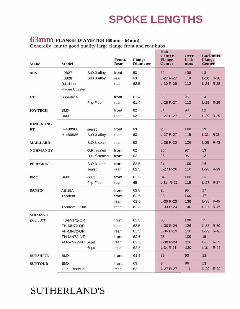
SPOKE LENGTHS
63mm FLANGE DIAMETER (60mm - 64mm)Generally: fair to good quality large flange front and rear hubs
Make ModelFront/Rear
FlangeDiameter
HubCenter-FlangeCenter
OverLock-nuts
Locknuts-FlangeCenter
ACS 1 0827 B.O.3 alloy front 63 32 1 00 1 8
1 0828 B.O.3 alloy rear 63 L-27 R-27 110 L-28 R-28
R.L. Hub rear 62.5 L-30 R-26 112 L-24 R-28
- Free Coaster
GT Superlace front 61.4 35 95 13
Flip-Flop rear 61.4 L-28 R-27 112 L-28 R-29
JOY TECH BMX front 62 34 93 1 2
BMX rear 62 L-27 R-27 112 L-29 R-29
KING KONG
KT H-480988 sealed front 63 31 1 00 19
H-480986 B.O.3 alloy rear 63 L-27 R-27 115 L-31 R-31
MAILLARD B.O.3-sealed rear 62 L-38 R-20 126 L-25 R-43
NORMANDY Q.R. sealed front 62 36 97 13
B.0. 3 -sealed front 62 36 95 12
PEREGRINE B.O.3 steel front 62.5 34 100 1 6
sealed rear 62.5 L-27 R-26 110 L-28 R-29
PMC BMX 6061 front 63.6 34 1 00 1 6
Flip-Flop rear 65 L-31 R- 31 115 L-27 R-27
SANSIN AE-15A front 62.5 31 95 17
Tandem front 62.6 33 1 00 17
rear 62.6 L-30 R-23 136 L-38 R-45
Tandem Drum rear 62.3 L-33 R-24 140 L-37 R-46
SHIMANO
Deore XT HB-MN72-QR front 62.5 35 1 00 15
FH-MN72-QR rear 62.5 L-30 R-24 126 L-33 R-39
FH-MN72-QR rear 62.5 L-36 R-19 130 L-29 R-46
FH-MN72-NT front 62.5 35 100 15
FH-MN72-NT 5spd rear 62.5 L-30 R-24 126 L-33 R-39
6spd rear 62.5 L-34 R-21 130 L-31 R-44
SUNSHINE BMX front 61.5 35 93 12
SUNTOUR BMX front 63 34 96 13
Dual Freehub rear 62 L-27 R-27 111 L-29 R-29
SUTHERLAND'S

SPOKE LENGTHS
63mm FLANGE DIAMETER (60mm - 64mm)Generally: fair to good quality large flange front and rear hubs
Make ModelFront/Rear
FlangeDiameter
HubCenter-FlangeCenter
OverLock-nuts
Locknuts-FlangeCenter
SUZUE
Wheelchair WH-3B B.0.3 rear 62 49 71
WH-3C Q.R. rear 62.5 49 69
CH-1 28H front 62 25 71 11
BMX SIL-BMX front 62.5 32 97 17
rear 62.5 L-27 R-27 109 L-28 R-28
SIL-SB-BMX front 63 31 96 17
rear 62.5 L-26 R-26 110 L-29 R-29 -
Tandem front 63 35 1 00 15rear 63 L-27 R-27 140 L-43 R-43
63mm footnotes
3 Bolt-on.
SUTHERLAND'S

SPOKE LENGTHS
67mm FLANGE DIAMETER (65mm - 69mm)Generally: quality large flange front and rear hubs
Make ModelFront/Rear
FlangeDiameter
HubCenter-FlangeCenter
OverLock-nuts
Locknuts-FlangeCenter
CAMPAGNOLO
NEW Centaur 6,7spd rear 67.5 L-36 R-21 126.5 L-27 R-43
6,7spd rear 67.5 L-37 R-17 130 L-28 R-48
Euclid 6,7spd rear 67.5 L-37 R-17 1 30 L-28 R-48
OLD Record front 67,5 34 1 00 1 6
5spd rear 67.5 L-34 R-22 1 20 L-26 R-38
6,7spd rear 67.5 L-36 R-21 126.5 L-27 R-43
Nuovo Record 5spd rear 67.5 L-34 R-22 120 L-26 R-38
Gran Sport 5spd rear 67.5 L-34 R-18 120 L-27 R-40
Gran Sport 5spd rear 67.5 L-34 R-18 121.5 L-27 R-43
Super Record Track rear 67.5 L-44 R-31 120 L-16 R-29
Record Track rear 67.5 L-44 R-31 120 L-16 R-29
Nuovo Record Track rear 67.5 L-44 R-31 120 L-16 R-29
C-Record Track rear 67.5 L-44 R-31 1 20 L-16 R-29
Tandem front 65 32 100 1 8
Tandem 8spd rear 65 L-36 R-20 140 L-34 R-50
Mtn. Tandem 7spd rear 65 L-36 R-20 140 L-34 R-50
HI-E 121 rear 67 L-35 R-24 121 L-26 R-37
1 27 rear 67 L-38 R-21 127 L-25 R-43
1 30 rear 67 L-36 R-23 1 30 L-29 R-43
131 rear 67 L-40 R-18 131 L-25 R-47
PHIL WOOD
Track front. 67.5 34 1 00 1 61spdrear 67.5 L-44 R-29 120 L-16 R-31
2spd 2 rear 67.5 L-29 R-29 120 L-31 R-31
1spd rear 67.5 L-44 R-29 126.5 L-20 R-34
1 spd rear 67.5 L-29 R-29 130 L-36 R-36
Tandem front 67.5 34 100 1 6
front 67.5 34 110 21
7spd rear 67.5 L-33 R-19 126.5 L-31 R-44
7spd rear 67.5 L-31 R-21 130 L-34 R-44
7spd 2 rear 67.5 L-23 R-23 135 L-44 R-44
8spd rear 67.5 L-33 R-18 135 L-34 R-49
7spd 2 rear 67.5 L-26 R-26 140 L-44 R-44
8spd 2 rear 67.5 L-31 R-21 140 L-39 R-49
7spd 2 rear 67.5 L-28 R-28 145 L-44 R-44
8spd 2 rear 67.5 L-23 R-23 145 L-49 R-49
SUTHERLAND'S

SPOKE LENGTHS
67MM FLANGE DIAMETER (65mm - 69mm)Generally: quality large flange front and rear hubs
Make ModelFront/Rear
FlangeDiameter
HubCenter-FlangeCenter
OverLock-nuts
Locknuts-FlangeCenter
PHIL WOOD (cont'd )
Tandem? 7spd 2 rear 67.5 L-31 R-31 150 L-44 R-44
8spd 2 rear 67.5 L-26 R-26 150 L-49 R-49
8spd 2 rear 67.5 L-28 R-28 155 L-49 R-49
8spd 2 rear 67,5 L-31 R-31 1 60 L-49 R-49
Tandem Brake Hubs
Arai Brake 7spd 2 rear 67.5
0
L-23 R-23 135 L-44 R-44
7spd 2 rear 67.5 L-26 R-26 1 40 L-44 R-44 1
8spd rear 67.5 L-26 R-21 140 L-44 R-49
7spd 2 rear 67.5 L-28 R-28 145 L-44 R-44
8spd 2 rear 67.5 L-23 R-23 145 L-50 R-50
7spd 2 rear 67.5 L-31 R-31 150 L-44 R-44
8spd 2 rear 67.5 L-26 R-26 150 L-49 R-49
8spd 2 rear 67.5 L-28 R-28 155 L-49 R-49
8spd 2 rear 67.5 L-31 R-31 1 60 L-49 R-49
Phil Brake 7spd rear 67.5 L-28 R-18 125 L-34 R-44
7spd rear 67.5 L-31 R-21 130 L-34 R-44 1
7spd 2 rear 67.5 L-23 R-23 135 L-44 R-44
8spd rear 67.5 L-33 R-18 135 L-34 R-49
7spd 2 rear 67.5 L-26 R-26 140 L-44 R-44
8spd rear 67.5 L-31 R-21 140 L-39 R-49
7spd 2 rear 67.5 L-28 R-28 145 L-45 R-44
8spd 2 rear 67.5 L-23 R-23 145 L-49 R-49
7spd 2 rear 67.5 L-31 R-31 150 L-44 R-44
8spd 2 rear 67.5 L-26 R-26 1 50 L-49 R-49
8spd 2 rear 67.5 L-28 R-28 1 55 L-49 R-49
8spd 2 rear 67.5 L-31 R-31 160 L-49 R-49
Standard Brake 7spd rear 67.5 L-33 R-19 126.5 L-31 R-44
7spd rear 67.5 L-31 R-21 1 30 L-34 R-44
7spd 2 rear 67.5 L-23 R-23 1 35 L-45 R-45
8spd rear 67.5 L-33 R-18 1 35 L-34 R-49
7spd 2 rear 67.5 L-26 R-26 1 40 L-44 R-44
8spd rear 67.5 L-31 R-21 1 40 L-39 R-49
7spd 2 rear 67.5 L-28 R-28 1 45 L-44 R-44
8spd rear 67.5 L-23 R-23 1 45 L-49 R-49
7spd 2 rear 67.5 L-31 R-31 1 50 L-44 R-44
8spd rear 67.5 L-26 R-26 1 50 L-49 R-49
8spd rear 67.5 L-28 R-28 155 L-49 R-49
8spd rear 67.5 L-31 R-31 1 60 L-49 R-49
SUTHERLAND'S

SPOKE LENGTHS
67MM FLANGE DIAMETER (65mm - 69mm)Generally: quality large flange front and rear hubs
Make ModelFront/Rear
Hub
Center—Flange FlangeDiameter Center
OverLock-nuts
Locknuts-FlangeCenter
PHIL WOOD (cont'd)
Front Brake Hubs and Front Suspension
Standard Brake front 67.5 27 110 28
front 67.5 28 115 29
Phil Brake front 67.5 25 110 29
front 67.5 28 115 29
BMX
F SA front 67.5 100 1 6
front 67.5 110 21
Flip-Flop rear 67.5 27 R-27 110 L-28 R-281spd rear 67.5 27 R-27 110 L-28 R-28
1spd rear 67.5 '27 R-27 117 L-31 R-31
1spd rear 67.5 27 R-27 1 20 L-33 R-33
SACHS
Orbit Standard 5spd rear 67 35 R-22 122 L-26 R-39
6spd rear * L-67 R-54 -36 R-19 126 L-27 R-44
7spd rear * L-67 R-54 L-39 R-18 130 L-26 R-47
ATB 6spd rear * L-67 R-54 L-38 R-19 126 L-25 R-44
7spd rear * L-67 R-54 L-39 R-18 130 L-26 R-47
3x7 H21101 rear * 67 L-37 R-18 130 L-28 R-47
Pentasport HS103 standard rear 1 75 L-30 R-29 122 L-31 R-32
H5113 coaster rear 1 75 L-30 R-29 1 22 L-31 R-32
H5213 5 spd push-pull rear 1 75 L-30 R-29 1 22 L-31 R-32
Super 7 H7201 rear 1 75 L-36 R-33 130 L-29 R-32
H7213 coaster rear 1 75 L-36 R-33 130 L-29 R-32
SANSIN Track front 67 34 100 1 6
rear 67 L-39 R-39 136 L-29 R-29
SHIMANO
Dura-Ace HB-7600 track front 67 35 1 00 15
Duro-Ace HB-7600 track rear 67 L-41 R-31 120 L-19 R-29
STURMEY ARCHER
AW, 55 rear 65 L-29 R-27 110 L-26 R-28
S3C rear 65 L-30 R-25 115 L-28 R-33
ABC Drum brake 3spd rear ** L-102.5 R-66 L-40 R-26 117 L-19 R-33
SABC Steellite drum brake 3spd rear L-84 R-65 L-35 R-26 118 L-24 R-33
SUTHERLAND'S

HubCenter- Over Locknuts-Flange Lock- FlangeCenter nuts Center
1-28 R-26 111 L-27 R-29
31 1 00 1 9
L-36 R-31 119 L-24 R-28
SPOKE LENGTHS
67mm FLANGE DIAMETER (65mm - 69mm)Generally: quality large flange front and rear hubs
Front/ FlangeMake Model Rear Diameter
SUNTOUR 3spd rear 65
track front 67.5
rear 67.5
67mm footnotes
* See Spoke Length charts for 58mm Flange Diameter for small Flange side of hub.
** See Spoke Length charts for 102.5mm Flange Diameter for large flange side of hub.
1 Use 67mm charts. Add 1.6mm to spoke length on 36-hole.
2 Symmetric.
90mm FLANGE DIAMETER (80mm - 90mm)Generally: aluminum shell and drum brakes
Make ModelFront/Rear
FlangeDiameter
HubCenter-FlangeCenter
OverLock-nuts
Locknuts-FlangeCenter
BENDIX 2-speed rear 80 L-29 R-30 117 30
SACHS
Orbit Drum Brake 6spd rear 90 L-36 R-19 1 26 L-27 R-44
7spd rear 90 L-37 R-18 130 L-28 R-47
ATB Drum 6spd rear 90 L-36 R-19 1 26 L-27 R-44
7spd rear 90 L-37 R-18 130 L-28 R-47
Drum Brakes VT3000 front 87 26 1 00 24
HT3020 5spd rear 87 L-33 R-19 122 L-28 R-42
6spd rear 87 L-36 R-16 124 L-26 R-46
6spd rear 87 L-35 R-17 126 L-28 R-46
VT5000 front 90 L-30 R-26 1 00 L-20 R-24
HT5020 5spd rear 90 L-36 R-21 122 L-25 R-40
6spd rear 90 L-37 R-19 1 26 L-26 R-44
7spd rear 90 L-37 R-19 130 L-28 R-46
VT7000 front 90 L-30 R-26 100 L-20 R-24
HT7020 6spd rear 90 L-37 R-19 126 L-26 R-44
7spd rear 90 L-37 R-19 130 L-28 R-46
Galaxie HT5320 rear 87 L-34 R-21 122 L-27 R-40Galaxie HT6320 rear 87 L-36 R-19 126 L-27 R-44
SUTHERLAND'S
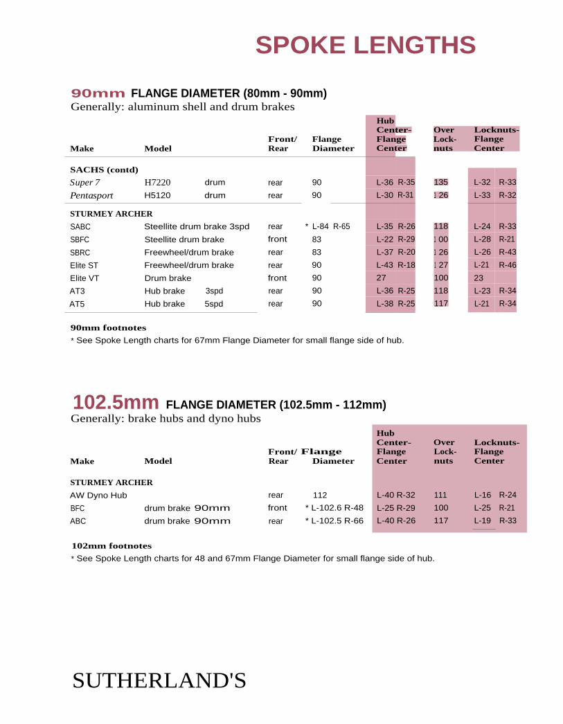
Over Locknuts-Lock- Flangenuts Center
L-32 R-33
L-33 R-32
L-24 R-33
L-28 R-21
L-26 R-43
L-21 R-46
23
L-23 R-34
L-21 R-34
135
1 26
118
1 00
1 26
1 27
100
118
117
HubCenter- Over Locknuts-Flange Lock- FlangeCenter nuts Center
111
100
117
L-16 R-24
L-25 R-21
L-19 R-33
L-40 R-32
L-25 R-29
L-40 R-26
SPOKE LENGTHS
90mm FLANGE DIAMETER (80mm - 90mm)Generally: aluminum shell and drum brakes
Make ModelFront/Rear
FlangeDiameter
HubCenter-FlangeCenter
SACHS (contd)
Super 7 H7220 drum rear 90 L-36 R-35
Pentasport H5120 drum rear 90 L-30 R-31
STURMEY ARCHER
SABC Steellite drum brake 3spd rear * L-84 R-65 L-35 R-26
SBFC Steellite drum brake front 83 L-22 R-29
SBRC Freewheel/drum brake rear 83 L-37 R-20
Elite ST Freewheel/drum brake rear 90 L-43 R-18
Elite VT Drum brake front 90 27
AT3 Hub brake 3spd rear 90 L-36 R-25
AT5 Hub brake 5spd rear 90 L-38 R-25
90mm footnotes
* See Spoke Length charts for 67mm Flange Diameter for small flange side of hub.
102.5mm FLANGE DIAMETER (102.5mm - 112mm)Generally: brake hubs and dyno hubs
Front/ FlangeMake Model Rear Diameter
STURMEY ARCHER
AW Dyno Hub rear 112
BFC drum brake 90mm front * L-102.6 R-48
ABC drum brake 90mm rear * L-102.5 R-66
102mm footnotes
* See Spoke Length charts for 48 and 67mm Flange Diameter for small flange side of hub.
SUTHERLAND'S

SPOKE LENGTHS
SUTHERLAND'S

REAR HUBLEFT AND RIGHT MEASUREMENTS
Left Right(L) hub (R) hubcenter center
to flange to flangecenter center
SPOKE LENGTHS CALCULATING SPOKE LENGTH
1st Step (cont'd)
FRONT HUB MEASUREMENT
Over locknut s
Locknut Hub Left (L)to center to locknut
flange flange to flangecenter center , I center
Right (R)locknut
to flangecenter
34mm FLANGE DIAMETER (33mm - 36mm)Generally: fair to good quality small flange front hubs
HubCenter— Over Locknuts-
Front/ Flange Flange Lock- FlangeMake Model Rear Diameter Center nuts Center
NUKE PROOF OEM aluminum front 35.5 38 1 00 1 2
4Omm FLANGE DIAMETER (37mm - 42mm)Generally: good to high quality small flange front hubs
HubCenter— Over Locknuts-
Front/ Flange Flange Lock- FlangeMake Model Rear Diameter Center nuts Center
ANSWER Manitou-EFC suspension front 38 40 1 00 N/A
FALCON Dynahub MTB Q.R. front 38 35 100 15
Road Q.R. front 40 32 1 00 1 8
KING suspension front 40 37 100 1 3
NUKE PROOF Bomb Shell carbon front 42 33 100 1 7
PRIMO Standard BMX9 front 38.1 32 96 1 6
Pro-Comp BMX9 front 38.4 32 96 1 6
SUTHERLAND'S

SPOKE LENGTHS
4Omm FLANGE DIAMETER (37mm - 42mm)Generally: good to high quality small flange front hubs
Make Model Rear Diameter Center nuts Center
Hub
Front/ Flange Flange Lock- FlangeCenter– Over Locknuts-
SHIMANO
Deore (Japan) HB-MT60 front 38 34 1 00 1 6
Deore (Japan) HB-MT60 B.0.2 front 38 34 100 1 6
105 (SC) HB-1055 front 38 36 100 1 4
RSX (SH) HB-A410 front 38.2 34 100 1 6
XTR HB-M900 front 38 37 100 1 3
Deore XT (SA) HB-M738 parallax front 38.1 34 100 15
STX-RC (51) HB-MC33 parallax front 38.2 34 100 1 6
Acera X(S1) HB-M290 parallax front 38.2 34 100 1 6
TREK System 28 front 40 36 100 1 4
System 3 8 front 40 36 100 1 4
UNION/HOPE Fatso suspension front 40.9 34 100 1 6
suspension front 41 32 100 18
Be Fast road/MTB front 41 35 100 15
TI-glide 7,8spd cassette rear 40.9 L-35 R-17 130 L-30 R-48
TI-glide 7,8spd cassette rear 41 L-34 R-20 135 L-34 R-48
WILDERNESS
TRAILS Momentum front 40 34 100 16
DPP MTB front 42.2 1 00 14
Road 7,8spd cassette rear 42.3 -36 R-20 130 L-29 R-45
Road 8spd threaded rear 41.5 0 R-17 130 L-25 R-48
40mm footnotes
See Spoke Length chart for 40, 44.5, and 48mm Flange Diameter for large flange side of huh.
** See Spoke Length chart for 31mm Flange Diameter for small flange side of hub.
1 7-speed cassette with added 11-tooth cog.
2 Bolt-on.
3 19 and 25mm axle end caps available.
4 1 9 and 31.5mm axle end caps available.
5 All Pulstar hubs require straight-pull spokes. Add 5mm to ail spoke lengths.28-hole and 32-hole work only for 3-cross. 36-hole hubs work only for 4-cross.
6 Fits Shimano cassettes.
7 15mm axle end cap.
8 System 2 - cup and cone bearing, System 3 - cartridge bearing.
9 Allen locking cone.
SUTHERLAND'S
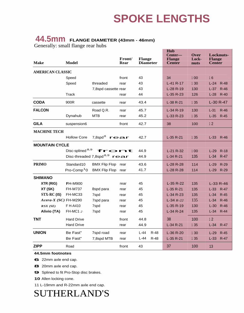
SPOKE LENGTHS
44.5mm FLANGE DIAMETER (43mm - 46mm)Generally: small flange rear hubs
HubCenter— Over Locknuts-
Front/ Flange Flange Lock- FlangeMake Model Rear Diameter Center nuts Center
AMERICAN CLASSICSpeed front 43 34 1 00 1 6 .
Speed threaded rear 43 L-41 R-17 1 30 L-24 R-48
7,8spd cassette rear 43 L-28 R-19 130 L-37 R-46
Track rear 44 L-35 R-23 126 L-28 R-40
CODA 900R cassette rear 43.4 L-38 R-21 1 35 L-30 R-47
FALCON Road Q.R. rear 45.7 L-34 R-19 130 L-31 R-46
Dynahub MTB rear 45.2 L-33 R-23 1 35 L-35 R-45
GILA suspension6 front 42.7 38 100 1 2
MACHINE TECHHollow Core 7,8spd8rear 42.7 L-35 R-21 1 35 L-33 R-46
MOUNTAIN CYCLEDisc-splined 8,9 front 44.9 L-21 R-32 1 00 L-29 R-18
Disc-threaded 7,8spd8,9 rear 44.9 L-34 R-21 135 L-34 R-47
PRIMO Standard10 BMX Flip Flop rear 43.6 L-28 R-28 114 L-29 R-29
Pro-Comp10 BMX Flip Flop rear 41.7 L-28 R-28 114 L-29 R-29
SHIMANOXTR (RIG) FH-M900 rear 45 L-35 R-22 135 L-33 R-46
XT (SK) FH-M737 8spd para rear 45 L-35 R-21 135 L-33 R-47
STX-RC (IS) FH-MC33 7spd rear 45 L-34 R-23 135 L-34 R-45
Acera-X (SC) FH-M290 7spd para rear 45 L-34 R-22 135 L-34 R-46
RSX (SE) F H-A410 7spd rear 45 L-35 R-19 130 L-30 R-46
Alivio (TA) FH-MC1 2 7spd rear 45 L-34 R-24 135 L-34 R-44
TNT Hard Drive front 44.8 38 100 1 2Hard Drive rear 44.9 L-34 R-21 1 35 L-34 R-47
UNION Be Fast" 7spd road rear L-44 R-48 L-36 R-20 1 30 L-29 R-45
Be Fast" 7,8spd MTB rear L-44 R-48 L-35 R-21 1 35 L-33 R-47
ZIPP Road front 43 37 100 13
44.5mm footnotes
6 22mm axle end cap.
8 20mm axle end cap.
9 Splined to fit Pro-Stop disc brakes.
10 Allen locking cone.
11 L-19mm and R-22mm axle end cap.
SUTHERLAND'S

Over Locknuts—'Lock- Flangenuts Center
94 15 -
1 08 L-26 R-25
125 L-28 R-42
SPOKE LENGTHS
48mm FLANGE DIAMETER (47mm - 52mm)Generally: medium flange and coaster brakes
HubCenter— Over
ILocknuts-
Front/ Flange Flange Lock- FlangeMake Model Rear Diameter Center nuts Center
FALCON Type D coaster rear 51 L-28 R-28 1 09 L-27 R-27Type E coaster rear 49 L-27 R-23 112 L-29 R-33
rear 46 L-30 R-24 135 L-38 R-44
UNION Be Fast 7spd road rear L-44 R-48 .-36 R-20 130 L-29 R-45Be Fast 7,8s pd MTB rear L-44 R-48 .5 R-21 135 L-33 R-47
48mm footnotes
* See Spoke Length chart for 31, 34, 40, and 45mm Flange Diameter for small flange side of hub.
** See Spoke Length chart for 58, 67mm Flange Diameter for large flange side of hub.
*** See Spoke Length chart for 102.5mm Flange Diameter for large flange side of hub.
1 Spoke heads are alternately recessed (chamfered) on the flange.
2 Symmetric (non-dished) rear wheel configuration.
3 Bolt-on.
4 Add 5mm to all spoke lengths. 28-hole and 32-hole work only for 3-cross.36-hole hubs work only for 4-cross. Ignore the fact that the spoke heads cross at the flange.
5 L-19mm and R-22mm axle end cap.
58.m FLANGE DIAMETER (53mm - 60mm)Generally: ATB rear, large flange front and internally geared 3 speeds
Front/ FlangeMake Model Rear Diameter
PERFORMANCE
ISOLATOR suspension front 53
HubCenter— Over LocknutsFlange Lock- FlangeCenter nuts Center
29 1 00 21
63MM FLANGE DIAMETER (60mm - 64mm)Generally: fair to good quality large flange front and rear hubs
HubCenter
Front/ Flange FlangeMake Model Rear Diameter Center
HYPER BMX B.0.3 front 61 32
BMX B.0.3 rear 61 L-28 R-29
STURMEY Sprinter 5spd w/o brake rear 65.2 L-35 R-21
SUTHERLAND'S

SPOKE LENGTHS
90mm FLANGE DIAMETER (80mm - 90mm)Generally: aluminum shell and drum brakes
Front/ FlangeMake Model Rear Diameter
HubCenter-FlangeCenter
OverLock-nuts
Locknuts-FlangeCenter
SHIMANO
INTER 7 internal 7spd rear 87 L-29 R-22
34
130
100
L-36 R-43
WESTPINE
Neutron-HC suspension front 91 1 6
1 02.5mm FLANGE DIAMETER (80mm - 90mm)Generally: brake hubs, dyno hubs and suspension hubs
Front/ FlangeMake Model Rear Diameter
HubCenter-FlangeCenter
OverLock-nuts
Locknuts-FlangeCenter
WESTPINE
Neutron-DH suspension front 112.5 34 100 1 6
SUTHERLAND'S

SPOKE LENGTHS
SUTHERLAND'S

CONTENTS
11
Step 2: 27" Rims
Approximate dimensions ....... 38
Calculating ............................... 38
Differences in hubs ................. 38
Right rear hubspoke length ....................... 38
27" spoke lengthcharts .................................. 39
Step 3: 27" Rims
Identifying rims ........................ 40
27" rim correctionfactors ........................... 40-44additions 8/95 ................ 44a
SUTHERLAND'S

27" ROAD SPOKE LENGTHS
2nd Step of 3 steps:27"and 28" RimsCount the number of holes in the hub anddecide on a spiking pattern, i.e. 4-cross, 3-cross,(4X, 3X) etc. Find the length listed for that com-
bination in the hub flange diameter categoryselected in step 1. Write down the length. Forthe right rear of multi-speed freewheel hubssubtract 2mm. (See below Tor details.)
Adjustments will also be needed for hubs thatare different from the specifications below.
The tables on the facing page will give you a length for the theoretical rim diameter of a 630mm
rim. Step 3 (rim correction factor) will adjust these lengths for the exact rim you have.
Approximate DimensionsThe following hub dimensions were used for the tables on the opposite page. They are the
approximate dimensions for road hike front hubs and the left rear of a road bike rear hub.
Huh center to flange center - 35mm
Spoke hole diameter - 2.6mm
Spoke seating and stretch - 0.4mm
Differences in Hubs
27" Example One: Shimano Dura-Acefront hub with 32 holes. Look at the40mm hub flange diameter table. For 3Xwheel write down the length 308mm,
27" Example Two: Mavic 500 rear hubwith 36 holes. On the 44.5mm table a 3Xwheel indicates a length of 305mm for theleft side. For the right side use 303 mm.
Many hubs differ from the hub dimensions
listed above so adjustments may need to he
made as follows:
Huh center to flange center - a 1mm differ-
ence will make a 0.1mm difference in finalspoke length.
27" Example Three: A front track hubwith a 45mm hub center to flange centeris 10mm wider than the dimensions thesetables are based on. Multiplying 10mm by0.1mm you get 1mm. Add 1mm to thefinal spoke length.
Spoke hole size - a 0.2mm difference in will make a 0.1mm difference in the final spoke length.
In practice this is usually not enough difference to matter.
Right Rear Hub Spoke LengthMost right rear road hubs require a shorter spoke. How muchshorter varies. Many hubs have a hub center to flange centeron the right rear of 20mm. This is a 15mm difference from thetables. Using the guidelines for differences in hub center to
flange dimensions, subtract 1.5mm for the right rearspokes. This is usually rounded up to 2mm.
3rd Step - go to page 11-40
SUTHERLAND'S
These combinationshave the same spokelength:
16 hole 1X = 32 hole 2X20 hole 2X = 40 hole 4X24 hole 2X = 48 hole 4X

484036322824
40 mm Flange Diameter
313 308310312
304* 301* 300*305 301* 300*306 301* 300*308 302* 300*
299* 298*299* 298*300* 298*300* 298*301* 298*
310 306 302*,313 307 302*
309 304312 305
307
27" ROAD SPOKE LENGTHS31 mm Flange Diameter
5X 4X 3X 2X 1 X radial
34mm Flange Diameter5X 4X 3X 2X 1 X radial
44.5mm Flange Diameter
484036322824
4840363228
5X 4X 3X 2X 1 X radial
4840363228
5X 4X 3X 2X 1 X radial
311 306310312
302304306308A311
298*299*300*302303
296*296*297*297*297*
295*295*295*295*295*
310 305309ill2
300303305301311
296*298*299*300302
294*294*295*295*295*
293*293*293*293*293*
48mm
4840363228
Flange Diameter5X 4X 3X 2X 1 X radial
58mm
4840363228
Flange Diameter5X 4X 3X 2X 1X radial
310 304309312
299302304307311
295*296*297*299301
292*293*293*293*294*
291*291*291*291*291*
309 302308
296299302305310
291*292*294*296298
288*288*288*289*290*
286*286*286*286*286*
63mm
4840363228
Flange Diameter5X 4X 3X 2X 1 X radial
67mm
4840363228
Flange Diameter5X 4X 3X 2X 1 X radial
309 301307311
294298301
310
289*291*292*294297
285*286*286*287*287*
284*284*284*284*284*
308 300307311
293297300304310
287*289*291*293296
283*284*284*285*286*
282*
282*282*282*282*
90mm Flange Diameter
4840363228
5X 4X 3X 2X 1 X radial
307 295304
285291
901
308
277*280*282 k
285*290*
272*273*274*274*276*
271*271*271*271*271*
102.5mm Flange Diameter
48403632
5X 4X 3X 2X 1 X radial
293 282288293299
272*276*278*282
266*267*268*269*
264*264*264*264*
* Hubs using these combinations must match the diameter category exactly for accurateresults. (See drawings and text page on 11 -4.)
SUTHERLAND'S

Rim withsingle eyelet
Rim withdouble eyelet
5 !621
5 6201-5 6201
27" ROAD SPOKE LENGTHS
3rd Step of 3 steps:27" and 28" RimsFind the rim in the tables below. Subtract the
ri m correction factor from the number youcame up with in step 2. The answer is the final
length of the spoke you need.
Identifying RimsRims arc grouped in descending order by bead
seat diameters. ISO rim markings are used in
these tables to help distinguish the variousmodels of rims. For an explanation of these
markings, (see page 12-3.)
The rim cross section drawings are not exact
representations of each rim.
Unless noted otherwise, rims listed do nothave eyelets or dimples.
27" Example One: Dura-Ace front hubwith an Araya SS-40 27 x 1 1/8 ri m. Rim cor-rection factor for this rim is -6. The lengthfrom step 2 is 308. 308 minus 6 is 302.302 is the final length.
27" Example Two: Mavic rear hub with aMavic 700C Open 4 ri m. The rim correc-tion factor for this rim is -12. The lengthsfrom step 2 are 305 minus 12 is 293 and303 minus 12 is 291. 293 and 291 are thefinal lengths.
Model
Model 1
EA 4
F
Model
50
Elite
Aero Elite
28 x11/2"
Rim Cross ISO/Make Material Section Distinguishing Features
Araya
24-635
25-635
27 x 1 1/4", 27 X 1 1/8" 27 x 1"
Rim Cross ISO/Make
Akront alloy
Ambrosio alloy
14-630 with rim washers
Alesa—see Weinmann (use old reference numbers)
Rim RimCorrection Spoke
Factor End Dia.
627
624
625
RimCorrection Spoke
Factor End Dia.
9 - 611
Sturmey-Archer steel
steel 24-635
Material Section Distinguishing Features
13-630
14-630 with single eyelets
2
3
2
SUTHERLAND'S

steel
CMC steel
Femco steel
Fiamme alloy
M.O. Mfg. steel
Marzorati MP alloy
Matrix alloy
12-630
13-630
1 3-630 with double eyelets
1 3-630 with double eyelets
13-630 with double eyelets
27" ROAD SPOKE LENGTHS27 x 1 1/4", 27 x 11/2", 27 x 1 " (contd)
Rim Cross ISO/Make Material Section Distinguishing Features
Araya alloy
13-630 with double eyelets
14-630 with double eyelets
14-630 with rim washers
16-630
20-630
1 6.5-630
20-630
18-630
18-630
14-630 with single eyelets
18-630
20-630
18-630
17-630 with single eyelets
1 3-630 with single eyelets
1 3-630 with single eyelets
Mag ic alloy
SUTHERLAND'S
Model
RimCorrection
Factor
RimSpoke
End Dia.
S5-45 -5 621
1 6A(5) -4 622
1 8 -3 624
5P-30 -4 622
16A(3) -3 623
20A -6 618
5S-40 -6 618_•
Aero 1W (ADX-1W) -8 615
Aero 2W (ADX-2W) -10 610
15 -4 623
Aero 4W (ADX-4W) -6 618
5H -3 6244
5 -3 624 I
-4 622
5 -3 623
80-Elan -5 603
71-Sport -2 609
-3 614
-3 624
Titan T -4 622
Titan -6 618
Titan Tour -8 613
ISO C -12 605
ISO C II -10 609
G40 -6 619
MA 2 -6 618
MA 40 -6 1 618
14-630
1 6-630
17-630
17-630
19-630
16-630

623 I622
27" ROAD SPOKE LENGTHS27x 1 1/4", 27 x 1 1/8", 27 x 1" (cont'd)
RimMake Material
Mag ic (coned) alloy
Milremo—see Wolber
Mistral—see Sun Metal
M.O. Mfg. steel
Nisi alloy
Rigida alloy
steel
Salurae alloy
(Specialized)
Schwinn steel
Sturmey-Archer steel
Sun Metal alloy
CrossSection
RimISO/ CorrectionDistinguishing Features Model Factor
1 3-630 with single eyelets Moldule E -5
13-630 with double eyelets Module E2 -4
13-630 with single eyelets MA -6
1 5-630 with double eyelets Module 3D Argent -6
15-630 with single eyelets Module 3 -6
19-630 with double eyelets Module 4 -6
20-630 -3
20-630 Sport-Toro-Strettisimo -5
13-630 with single eyelets AL 13/20 -6
13-630 with single eyelets Rush -6
1 6-630 with single eyelets AL 16/22 -4
1 7-630 Deco 30 -4
21-630 Deco 35 -4
16-630 with single eyelets C22 -4
14-630 with double eyelets HC19 -4
15-630 with double eyelets C20 -4
20-630 S-6 -5
20-630 EA25.0 -4
20-630 K25.0 -2
17-630 L17 -5
18-630 with single eyelets M17 -5
20-630 L20 -7
20-630 with single eyelets M20 -5
25-630 with single eyelets M25 -5
13 -630 L1 3 -6
13-630 with single eyelets M13 -6
Rim ISpoke
End Dia.
620
621 a618
619 •618
618
614
620
618
618
622
622
622
622
620A626
620
620
616
620
619
618
618
SUTHERLAND'S

alloy
alloyWolber
27 x 1 1/4", 27 x Ws", 27 x 1" (cont'd)
Rim Cross ISO/Make Material Section Distinguishing Features
Sun Metal (cont'd)
steel
Torelli alloy
Ukai—see similar Araya model:
Velocity alloy
13-630 with single eyelets
13-630 with single eyelets
16-630
16-630
14-630
14-630
18-630
13-630 with single eyelets
16-630
Weinmann (old reference numbers in parentheses)
15-630
16-630
16-630 with dimples
16-630 with single eyelets
17-630
13-630 with double eyelets
1 3-630 with single eyelets
14-630 with single eyelets
17-630 with double eyelets
14-630
1 6-630
16-630 with single eyelets
alloy
27" ROAD SPOKE LENGTHS
1 5-630
14-630 with double eyelets
14-630 with double eyelets
RimCorrection
Model Factor
RimSpoke
End Dia.
M1311 -6 618
M1 31_ -6 618
C16 -6 619
CR16 -8 615
M14A pre '91 -8 614
M14A '91 & after -10 611
Style L -3 624
Expert 27" -6 617
—619Twin Hollow -5
2115 -4 6222115 (716, 416, 116) -4 6222115 (716, 416, 116) -5 6202115 (716, 416, 116) -3 624
(256) -2 626
231 3 (913 SQR) -7 615(613)
(513 5)
-7 615II
-5 6192317 (917 SQR) -7 615
(514/Al24) -2 625 i(516/Al29) -3 624(516/Al29) -2 625
2215 (415X) -2 625
Gentleman GTA2 -4 622
Gentleman GTX -4 622
SUTHERLAND'S

27x 1 1/4" 27 x 1 1/8" 27 X 1 " (contd)
,
,
Rim Cross ISO/Make Material Section Distinguishing Features
Wolber/Super Champion
alloy 1 7-630 with single eyelets
1 7-630 with single eyelets
14-630 with double eyelets
14-630 with single eyelets
27" ROAD SPOKE LENGTHS
Model
RimCorrection
Factor
RimSpoke
End Dia.
Modele 58 -4 622
Modele 59 -4 622
T430 Alpine -4 622,
Gentleman 81 -5 620
SUTHERLAND'S

Rim withsingle eyelet
Rim withdouble eyelet
27" ROAD SPOKE LENGTHS
3rd Step of 3 steps:27" and 28" RimsFind the rim in the tables below. Subtract therim correction factor from the number youcame up with in step 2. The answer is the finallength of the spoke you need.
Identifying RimsRims are grouped in descending order by beadseat diameters. ISO ri m markings are used in
these tables to help distinguish the variousmodels of rims. For an explanation of thesemarkings, (see page 12-3.)
The rim cross section drawings are not exactrepresentations of each rim.
Unless noted otherwise, rims listed do riothave eyelets or dimples.27"
Example One: Dura-Ace front hubwith an Araya 55-40 27 x ri m. Rim cor-rection factor for this rim is -6. The lengthfrom step 2 is 308. 308 minus 6 is 302302 is the final length.
27" Example Two: Mavic rear hub with aMavic 700C Open 4 ri m. The rim correc-tion factor for this rim is -12. The lengthsfrom step 2 are 305 minus 12 is 293 and303 minus 12 is 291. 293 and 291 are thefinal lengths.
27 x 11/4" 27 x W8" 27 X 1"
,
,
Rim RimRim Cross ISO/ Correction Spoke
Make Material Section Distinguishing Features Model Factor End Dia.
van Schothorst steel
alloy
18-630 U 24 -4 621
17-630 AS 23X -5 619
SUTHERLAND'S

27" ROAD SPOKE LENGTHS
SUTHERLAND'S

11CONTENTS
Step 2: 700C Rims
Approximate dimensions ....... 46
Calculating ............................... 46
Differences in hubs ................. 46
Right rear hubspoke length ....................... 46
700C spoke lengthcharts .................................. 47
Step 3: 700C Rims
identifying rims ........................ 48
700C ri m correction factorsclinchers ........................ 48-55tubulars ......................... 56-60
additions 8/95 ............ 60a-b
SUTHERLAND'S

7000 ROAD SPOKE LENGTHS2nd Step of 3 steps700C RimsCount the number of holes in the huh and
decide on a spoking pattern, i.e. 4-cross, 3-cross,(4X, 3X) etc. Find the length listed for that com-bination in the huh flange diameter category
selected in step 1. Write down the length. Forthe right rear of multi-speed freewheel hubs
subtract 2mm. (See below for details.)Adjustments will also be needed for hubs thatare different fro m the specifications below.
700C Example One: Shimano Dura-Acefront hub with 32 holes. Look at the40mm hub flange diameter table. For 3Xwheel write down the length 308mm.
700C Example Two: Mavic 500 rear hubwith 36 holes. On the 44.5mm table a 3Xwheel indicates a length of 305mm for theleft side. For the right side use 303 mm.
The tables on the facing page will give you a length for the theoretical rim diameter of a 630mmri m. Step 3 trim correction factor) will adjust these lengths for the exact rim you have.
Approximate DimensionsThe following hub dimensions were used for the tables on the opposite page. They are the
approximate dimensions for road bike front hubs and the left rear of a road bike rear hub.
Hub center to flange center - 35mmSpoke hole diameter - 2.6mm
Spoke seating and stretch - 0.4mm
Differences in HubsMany hubs differ from the hub dimensionslisted above so adjustments may need to be
made as follows:
Huh center to flange center - a 1mm differ-ence will make a 0.1mm difference in final
spoke length.
Spoke hole size - a 0.2mm difference in will make a 0.1 mm difference in the final spoke length.
In practice this is usually not enough difference to matter.
Right Rear Hub Spoke LengthMost right rear road hubs require a shorter spoke. How muchshorter varies. Many hubs have a hub center to flange center
on the right rear of 20mm. This a 15mm difference from thetables. Using the guidelines for differences in huh center to
flange dimensions, subtract 1.5mm for the right rearspokes. This is usually rounded up to 2mm.
3rd Step - go to page 11-48
SUTHERLAND'S
700C Example Three: A front track hubwith a 45mm hub center to flange center ,is 10mm wider than the dimensions thesetables are based on. Multiplying 10mm by0.1mm you get 1mm. Add 1 mm to thefinal spoke length.
These combinationshave the same spokelength:
1 6 hole 1X = 32 hole 2X20 hole 2X = 40 hole 4X24 hole 2X = 48 hole 4X

3X
300303
305307
311
5X 4X
309 301307
4840363228
700C ROAD SPOKE LENGTHS31 mm Flange Diameter
484036322824
1
5X 4X
— ——
313
3X
——
308310312
2X
1
X radial
—
304*305306308
—
301*301*301*302*
--
300*300*300*300*
34mm Flange Diameter5X 4X 3X 2X 1 X radial
4840 310 306 302* 299* 298*36 313 307 302* 299* 298*32 309 304 300* 298*28 312 305 300* 298*24 307 301* 298*
40mm Flange Diameter5X 4X 3X 2X
48 311 306 302 298*40 310 304 299*36 312 306 300*32 30228 311 303
44.5mm Flange Diameter1 X radial
4840363228
5X 4X
296*296*297*297*297*
295*295*295*295*295*
310 305309
312
2X 1 X radial
296* 294* 293*298* 294* 293*299* 295* 293*300 295* 293*302 295* 293*
48mm Flange Diameter5X 4X 3X 2X 1 X radial
58mm Flange Diameter5X 4X 3X 2X 1 X radial
4840363228
310 304309
299302304
307 .
311
295*296*297*299301
292*293*293*293*294*
291*291*291*291 *291*
4840363228
309 302308
296
299302
305
310
291*292*294*296298
288*288*288*289*290*
286*286*286*286*286*
63mm Flange Diameter 67mm Flange Diameter3X 2X 1x radial
4840363228
5X 4X 3X 2X 1 X radial
294298301
305 ,
310
289*291*292*294297
285*286*286*287*287*
284*284*284*284*284*
308 300
307311
2932970004
310
287*289*291*293296
283*284*284*285*286*
282*282*282*282*282*
90mm Flange Diameter 1 02.5mm Flange Diameter
4840363228
5X 4X 3X 2X 1 X radial
48403632
5X 4X 3X 2X 1 X radial
307 295304311
285291295301308
277*280*282*285*290*
272*
273*274*274*276*
271*271*271*271*271*
293 282288
293299
272*276*278*282
266*267*268*269*
264*264*264*264*
* Hubs using these combinations must match the diameter category exactly for accurateresults. (See drawings and text page on 11-4.)
SUTHERLAND'S

Rim withsingle eyelet
Rim withdouble eyelet
27" Example One: Dura-Ace front hubwith an Araya 55-40 27 x 1 1/g ri m. Rim cor-rection factor for this rim is -6. The lengthfrom step 2 is 308. 308 minus 6 is 302.302 is the final length.
27" Example Two: Mavic rear hub with aMavic 700C Open 4 ri m. The rim correc-tion factor for this rim is -12. The lengthsfrom step 2 are 305 minus 12 is 293 and303 minus 12 is 291. 293 and 291 are thefinal lengths.
Akront alloy
Alesa alloy
stainless
steel
alloy
700C ROAD SPOKE LENGTHS
3rd Step of 3 steps700C RimsFind the rim in the tables below. Subtract theri m correction factor from the number youcame up with in step 2. The answer is the finallength of the spoke you need.
Identifying RimsRims are grouped in descending order by bead
seat diameters. ISO rim markings are used inthese tables to help distinguish the variousmodels of rims. For an explanation of thesemarkings, (see page 12-3.)
The rim cross section drawings are not exactrepresentations of each rim.
Unless noted otherwise, rims listed do nothave eyelets or dimples.
700C, 28 x 1 5/8"x 13/8"Rim Rim
Rim Cross ISO/ Correction SpokeMake Material Section Distinguishing Features Model Factor End Dia.
13-622 50 -9 613
17-622 with double eyelets 9017 -11 609
17-622 with single eyelets 6017 -11 608
22-622 with dimples 822 -9 612
17-622 with dimples 817 -7 617
20-622 with dimples 820 -8 614
Ambrosio—also see Weinmann for rims not listed here (use old reference numbers)
13-622 with double eyelets Elite Prisma -12 606
13-622 with double eyelets Super Elite -10 610
14-622 with single eyelets Super Elite -7 615
14-622 with double eyelets Elite City 22 -8 613
14-622 with single eyelets Elite -8 614
15-622 with single eyelets Central Park -11 608
SUTHERLAND'S

ISO/Distinguishing Features Model
RimCorrection
Factor
RimSpoke
End Dia.
1 4-622 with rim washers Aero Elite -12 605
1 4-622 SS-45 -8 613
16-622 16A(5) -8 615
1 6-622 SP-20 -8 615
1 7-622 1 8 -7 616
1 7-622 SP-30 -8 616
1 7-622 PX-35 -8 614
1 7-622 VX-300 -9 611
1 8-622 PX-45 -8 614
19-622 16A(3) -7 616
13-622 with double eyelets CTL-385 -10 610
1 4-622 CTL-370 -10 611
1 4-622 20A -10 611
14-622 with double eyelets 20A -9 611
1 4-622 with double eyelets S5-40 -9 611
14-622 with double eyelets VX-400 -8 614
1 3-622 Super Aero SA-530 -25
-- -
581
1 4-622 CT-19 -9 612
14-622 with rim washers Aero 1W (ADX-1 W) -12 607
16-622 Aero 2W (ADX-2W) -14 602
20-622 15 -8 615
16-622 Aero 4W (ADX-4W) -10 610
17-622 5H -7 616
13-622 with double eyelets Lambda Strada -8 614
13-622 with double eyelets Omega 19 -11 608
1 3-622 with double eyelets Omega Strada -8 614
13-622 with double eyelets Omicron Strada -8 614
Rim CrossMake Material Section
Ambrosio (cont'd)
Araya alloy
steel
Campagnolo alloy
700C ROAD SPOKE LENGTHS700C, 28 x 1 5/8"x 1 3/8" (cont'd)
SUTHERLAND'S

Rim CrossMake Material Section
Campagnolo alloy
(cont'd)
alloy
alloy
Euro-Asia alloy
Fiamme alloy
Fir alloy
Galli alloy
Matrix alloy
700C ROAD SPOKE LENGTHS700C, 28 x 1 5/8"X 1 3/8" (conttd)
ISO/Distinguishing Features Model
RimCorrection
Factor
RimSpoke
End Dia.
13-622 with double eyelets Ypsilon Strada -8 614
13-622 with single eyelets Gamma Strada -9•
612
14-622 with double eyelets Delta XL Strada -8 614
1 4-622 with double eyelets Omega XL Strada -8 614
1 3-622 Lambda Strada V -15 600
13-622 Omega Strada V -16 599
13-622 Ypsilon Strada V
Shama!
-16 599
13-622 with rim washers,
and special nipples -22 586
13-622 Arrow -24 582
1 4-622 with single eyelets 80 - Elan -9 611
1 8-622 71 - Sport -6 617
13-622 with double eyelets EL 20 -8 615
13-622 with double eyelets EL 45 -7 614
13-622 with double eyelets ES 35 -8 614
13-622 with double eyelets EU 90 -8 614
14-622 with double eyelets EA 50 -10 610
14-622 with double eyelets EA 60 -10 610
13-622 with rim washers Aero Pro -9 613
17-622 with single eyelets Titan T -8 614
1 2-622 with single eyelets Aurora -10 610
1 3-622 with double eyelets Journey -10 611
1 3-622 with double eyelets Sonic -13 604
1 3-622 with double eyelets Titan Tech -10 610
1 3-622 with single eyelets Titan -9 611
1 3-622 with single eyelets Titan S -9 611
SUTHERLAND'S
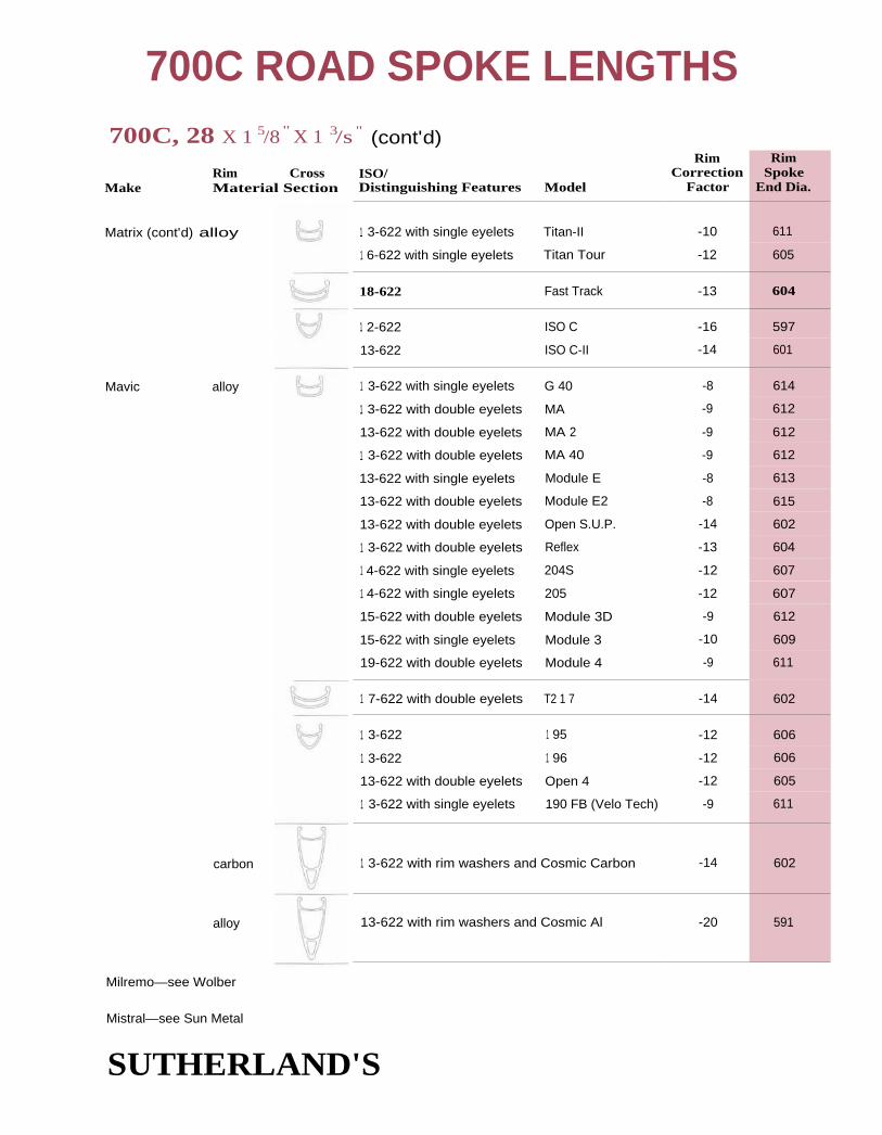
Rim CrossMake Material Section
Matrix (cont'd) alloy
Mavic alloy
carbon
alloy
Milremo—see Wolber
700C ROAD SPOKE LENGTHS700C, 28 X 1 5/8 " X 1 3/s " (cont'd)
ISO/Distinguishing Features Model
RimCorrection
Factor
RimSpoke
End Dia.
1 3-622 with single eyelets Titan-II -10 611
1 6-622 with single eyelets Titan Tour -12 605
18-622 Fast Track -13 604
1 2-622 ISO C -16 597
13-622 ISO C-II -14 601
1 3-622 with single eyelets G 40 -8 614
1 3-622 with double eyelets MA -9 612
13-622 with double eyelets MA 2 -9 612
1 3-622 with double eyelets MA 40 -9 612
13-622 with single eyelets Module E -8 613
13-622 with double eyelets Module E2 -8 615
13-622 with double eyelets Open S.U.P. -14 602
1 3-622 with double eyelets Reflex -13 604
1 4-622 with single eyelets 204S -12 607
1 4-622 with single eyelets 205 -12 607
15-622 with double eyelets Module 3D -9 612
15-622 with single eyelets Module 3 -10 609
19-622 with double eyelets Module 4 -9 611
1 7-622 with double eyelets T2 1 7 -14 602
1 3-622 1 95 -12 606
1 3-622 1 96 -12 606
13-622 with double eyelets Open 4 -12 605
1 3-622 with single eyelets 190 FB (Velo Tech) -9 611
1 3-622 with rim washers and Cosmic Carbon -14 602
13-622 with rim washers and Cosmic Al -20 591
Mistral—see Sun Metal
SUTHERLAND'S

614
-611
611
1 610
611
612
612
13-622 with double eyelets HLC 2000
13-622 with single eyelets Aero
1 3-622 with single eyelets Rush
16-622 with single eyelets AL 16/22
17-622 Deco 30
21-622 Deco 35
1 7-622 Vantage Comp
14-622 Vantage Comp Road
1 6-622 Vantage Cross-Sport
1 6-622 with single eyelets Rock 450CE
17-622 Rock 490C
1 3-622 with rim washers Featherweight
16-622 with single eyelets C22
1 4-622 with double eyelets HC19
1 5-622 with double eyelets C20
12-622 with single eyelets 2001 Prof. Profile SM
1 2-622 with single eyelets 2001 Prof. Profile SM
17-622 L17
17-622 with single eyelets M17
1 8-622 L18
13-622 Vantage Pro Aero
Rigida alloy
steel
Ritchey alloy
Saavedra
Saturae
(Specialized)
Sideral alloy
Sun Metal alloy
alloy
alloy
700C ROAD SPOKE LENGTHS700C, 28 X 1 5/8" x 1 3/8 " (cont'd)
RimRim Cross ISO/ Correction
Make Material Section Distinguishing Features Model Factor
1 2-622 with double eyelets HRB-22 -8
RimSpoke
End Dia.
11-622 with single eyelets Mixer -9
1 2-622 with single eyelets Mixer -9
1 2-622 with double eyelets Contender -9
13-622 with double eyelets Score -9
13-622 with double eyelets SX 100 -10
13-622 with single eyelets AL 13/20 -10
-12 606
-13 604
-10 610
-8 616
-8 615
-8 615
-10 611
-10 611
-9 613
-10 . 611
-10 611
-14 603
-9 612
-8 614
-8 614
-8 614
-13 604
-13 604
-8 613
-9 . 612
-10 I 611
SUTHERLAND'S

Sun Metal alloy
(cont'd)
steel
ToreIli alloy
Ukai—see similar Araya models
Velocity alloy
alloy
700C ROAD SPOKE LENGTHS700C, 28 x 1 5/8"x 1 3/8" (cont'd)
Rim RimRim Cross ISO/ Correction Spoke
Make Material Section Distinguishing Features Model Factor End Dia.
20-622 L20 -10 609
20-622 with single eyelets M20 -9 611
25-622 with single eyelets M25 -10 609
1 3-622 with single eyelets M13 -10 610
13-622 with single eyelets M1311 -10 610
13-622 with single eyelets M1 3L -9 612
15-622 CR16 -11 608
1 5-622 CR1611 -9 611
1 5-623 CRE16/CRT1611 -10 609
17-622 with single eyelets CR18 -9 612
20-622 CR20 -11 608
I20-622 Rhyno/SST20 -13 604
1 4-622 Mistral M14A
`91 and later -14 603
14-622 Mistral M14A pre '91 -12 606
1 4-622 with single eyelets ME14A -14 601
1 4-622 Venus -19 592
17-622 with single eyelets CR17A -12 605
18-622 Style L -3 624
13-622 with double eyelets Expert -10 610
12-622 with double eyelets Master -12 606
1 6-622 Twin Hollow -10 611
1 3-622 Aero -17 596
14-622 Arrowhead -16 598
Weinmann—(old reference numbers in parentheses)
145--622622 with single eyelets 414
215
-7
-7
61
15-622
15-622 2115 -7 615
SUTHERLAND'S

700C ROAD SPOKE LENGTHS700C, 28 x 1 5/8"x 1 3/8" (cont'd)
MakeRim Cross ISO/Material Section Distinguishing Features Model
Rim RimCorrection Spoke
Factor End Dia.
1 6-622 2115 (716, 416, 116) -8 614
16-622 with dimples 2115 (716, 416, 116) -9 612
16-622 with single eyelets 2115 (716, 416, 116) -7 616
20-622 drilled for
.120/12g spokes (720) -8 614
22-622 (722, 1 22) -9 612
13-622 with double eyelets 2313 -10 610
13-622 with double eyelets 2313 (913 SQR) -11 608
13-622 with single eyelets (613) -11 608
1 4-622 with single eyelets (513S) -9 612
1 4-622 with single eyelets 571 S -9 612
1 7-622 with double eyelets (91 7 SQR) -1 1 608
17-622 with single eyelets 2317 (617 SQR) -11 607
13-622 9013 -11 615
14-622 (514/Al24) -7 617
1 4-622 with single eyelets (514/Al24) -6 618
15-622 with single eyelets (515X) -5 619 'U
16-622 (516/A 129) -7 616
16-622 with single eyelets (516/A 129) -6 617
1 9-622 (419X) -7 617
18-622 217 -8 614
1 9-622 4019 -9 613
15-622 with single eyelets 2215 (415X) -6 619
15-622 2215 -7 614
22-622 with dimples (811) -9 612
22-622 with dimples (811 R) -8 613
20-622 with dimples (801) -8 614
1 4-622 with double eyelets Gentleman GTA2 -8 614
1 4-622 with double eyelets Gentleman GTX -8 614
SUTHERLAND'S
Weinmann—(old reference numbers in parentheses)
alloy
stainless
steel
Wolber alloy

700C, 28 x 1 5/8 " X 1 3/8 " (contd)
Rim Cross ISO/Make Material Section Distinguishing Features
Wolber/Super Champion
alloy
* Can be used with sew-ups too.
1 7-622 with single eyelets
1 7-622 with single eyelets
14-622 with double eyelets
14-622 with single eyelets
14-622
1 0-622
700C ROAD SPOKE LENGTHS
Model
RimCorrection
Factor
RimSpoke
End Dia.
Modele 58 -8 615
Modele 59 -8 615
T430 Alpine -8 614
Gentleman 81 -9 612
TX Profil -14 602
Mixte* -8 617
SUTHERLAND'S

Akront alloy
Alesa alloy
Ambrosio alloy
Araya alloy
Assos alloy
700C ROAD SPOKE LENGTHS700C Sew-up
Rim RimRim Cross ISO/ Correction Spoke
Make Material Section Distinguishing Features Model Factor End Dia.
20 -5 620
22.5 920 Eterno -6 • 617
22.5 920 Professional -7 617
22.5 920 Race -7 617
20 with double eyelets Crono -7 615
20 with double eyelets Formula 20 Crono -6 617
20 with double eyelets Montreal -6 617
20 with double eyelets Formula 20 Crono -6 617
21 with double eyelets Nemesis -7 616
22 with double eyelets Metamorphosis -6 618
22 with double eyelets Synthesis -6 618
1 9 with rim washer Aerodynamic -13 604
21 with double eyelets 1 6B Gold -6 618
21 with double eyelets 1 6B Red -6 618
21 with double eyelets Pro Staff 340 -5 619
21 with double eyelets Pro Staff 400 -5 619
21 with double eyelets R-50 -6 618
21 with double eyelets Tita-Ace -6 618
1 7.5 with single eyelets Aero 5 (ADX-S) -9 611
1 9 Aero 4 (ADX-4) -10 611
1 9 Super Aero 230 -23 584
19 with rim washer Aero 1 (ADX-1) -11 609
21 with rim washer Aero 2 (ADX-2) -12 607
18 with special
nipples and washert Unspecified Model - -2 627
t Rim requires special nipples and washers. Due to extra length of nipples, spokes could be up to 4mmshorter than listed here. Rims are drilled for specific lacings. Small holes are drilled in the tire bed nearthe valve hole to indicate lacing pattern. Two holes indicates radial both sides. One hole indicates radialone side and crossed the other side. No hole indicates crossed pattern on both sides.
SUTHERLAND'S

700C Sew-up (cont'd)
Rim CrossMake Material Section
Campagnolo alloy
Fiamme alloy
Fir alloy
Galli alloy
700C ROAD SPOKE LENGTHS
Rim RimISO/ Correction SpokeDistinguishing Features Model Factor End Dia.
20 with double eyelets Delta XL Strada -7 617
20 with double eyelets Lambda Strada -7 617
20 with double eyelets Omega Strada -7 617 I
20 with double eyelets Omega XL Strada -7 617
20 with double eyelets Record Crono -7 617
20 with double eyelets Record Pave -7 617
20 with double eyelets Record Strada -7 617
20 with double eyelets Sigma 20 Strada -7 617
20 with double eyelets Sigma Crono -7 617
20 with double eyelets Sigma Keirin -7 617
20 with double eyelets Sigma XL Keirin -7 617
20 with double eyelets Victory Crono -7 617
20 with double eyelets Victory Strada -7 617
22 with double eyelets Sigma Pave -7 617
22 with double eyelets Sigma Strada -7 , 617
19 with rim washers Shamal -22 586
18.5 with double eyelets Speedy (Track) -6 617
20 with double eyelets Ergal (Yellow Lbl) -6 61 7
21 with double eyelets Ergal-Iride -6 617
21 with double eyelets Hard Silver -7 6151
21 with double eyelets Master -6 I 617
21 with double eyelets RCX -7 616
21 with double eyelets Red Label -6 617
21 with double eyelets Super Corsa -7 615
18 with double eyelets Alkor -7 617
20 with double eyelets Isidis -6 617
20 with double eyelets Pulsar -6 618
20 with double eyelets Quasar -6 618
20 with double eyelets Sirus -6 618
20 with single eyelets Criterium -6 618
20 with single eyelets Paris-Roubaix -7 61 7
SUTHERLAND'S

Galli (cont'd) alloy
Gimondi alloy
Hi-E alloy
Matrix alloy
Mavic alloy
700C ROAD SPOKE LENGTHS700C Sew-up (cont'd)
Rim RimRim Cross ISO/ Correction Spoke
Make Material Section Distinguishing Features Model Factor End Dia.
20 with single eyelets Servizio Corse -6 618
20 with single eyelets Top Pro -6 618
21.5 with with double eyelets Bravo 45D -6 619
21 with special nipples -11 612
21 with double eyelets Photon -8 615
21 with double eyelets Photon -8 615
1 8.5 with square washers Iso -8 614
18.5 without washers Iso -9 612
18 with double eyelets CX-18 -7 616
20 with double eyelets Argent 8 -7 615
20 with double eyelets Argent 10 -7 615
20 with double eyelets Argent 12 SSC -7 616 I20 with double eyelets Bleu SSC -7 616
20 with double eyelets G.E.L. 280 -7 615
20 with double eyelets G.L. 330 -7 615
20 with double eyelets GP4 (Pre-'94) -7 615
20 with double eyelets GP-4 '94 (and later?) -10 611
20 with double eyelets OR10 -7 615
20 with single eyelets Piste (Track) -6 617
20.5 with double eyelets Montlhéry Legere -7 615
20.5 with double eyelets MontIlhery Pro -7 616
21.5 with double eyelets Montlhéry Route -8 614
21.5 with double eyelets Paris Roubaix SSC -7 616
22 with double eyelets Argent 7 -7 615
22 with double eyelets OR 7 -7 615
22 with single eyelets Speciale Sport -8 614
1 8.5 with double eyelets CXP 25** -6 618
1 9 with double eyelets Mach 2 CD 2 -13 605
1 9 with single eyelets Mach 2 CD -14 603
** Requires nipple with hex heads. Spoke length can be up to 3mm shorter than listed.
SUTHERLAND'S

Mistral—see Sun Metal
Nisi alloy
700C ROAD SPOKE LENGTHS
700C Sew-up (contd)
Make
RimSpoke
End Dia.
RimRim Cross ISO/ CorrectionMaterial Section Distinguishing Features Model Factor
1 9 Pista Speciale (Track)
19 with double eyelets Sludi Mod 290
19 with double eyelets Sludi Mod 320
20 with double eyelets AN-85
20 with double eyelets Countach
20 with double eyelets Solidal
21 with double eyelets G-27
-5 620
-6 618
-6 618
-6 617
-7 617
-6 617
-6 618
Rigida alloy
Saavedra alloy
Saturae alloy
Sideral alloy
Sun Metal alloy
1 9 with single eyelets Laser
21.5 with double eyelets Club
21.5 with double eyelets Pro
21.5 with double eyelets SC 200
19 with rim washers Turbo
all HT
19 with single eyelets 2001 Prof. Profile LM
21 with double eyelets M20B
-10 610
-8 614,
-8 613
-9 613
-10 609
-6 618 ,
-9 612
-8 613
Weinmann alloy
Wolber/Super Champion
alloy
Super Champion—see Wolber
Ukai—see similar Araya
660133
604
617
617
617
18.5 M19AII -13
17 M17A -9
1 9 M19A -13
22.5 904 Professional -7
22.5 906 Race -7
22.5 Carrera "AS" -6
20 with double eyelets Arc-en-del -7
20 with double eyelets Aspin/Aspen -7
20 with double eyelets Aubisque -7
616
616
616
SUTHERLAND'S

alloy
17.5 Profil 18
1 9 Profil 20
20 440
700C ROAD SPOKE LENGTHS700C Sew-up (cont'd)
RimRim Cross 150/ Correction
Make Material Section Distinguishing Features Model Factor
Wolber/Super Champion (cont'd)
20 with double eyelets Com petition
20 with double eyelets Medaille d'Or
Zipp carbon fiber
RimeSpoke
End Dia.
1
-7 616
-7 616
-10 610
-14 601
-51 528
SUTHERLAND'S

1;
2
6141
609
603
607.
[ RimSpoke
End Dia.
615
11-616
614
610
609
614
612
603
607
604
581
61 1
611
587
Rim CrossMake Material Section
Alesa alloy
Araya alloy
Campagnolo alloy
Matrix alloy
Magic alloy
Rigida alloy
Sun Metal alloy
Torelli alloy
700C ROAD SPOKE LENGTHS700C, 28 x 1 5/8" X 1 3/8"
RimISO/ CorrectionDistinguishing Features Model Factor
17-622 317, 717 -8
19-622 419X -7
17-622 VX-300 -8
13-622 CT-19N -10
13-622 SA-530C Super Aero -25
13-622 with double eyelets Omega 20 -8
17-622 with single eyelets Dedra -10
14-622 needs hex head Jetnipples and wrench to true
-14
16-622 with single eyelets Titan Tour -12
13-622 with single eyelets 1 92 -10
17-622 AS25 -8
20-622 AS26F -9
1 3-622 SHP 6 -13
14-622 with single eyelets Excel 7 -12
18-622 with single eyelets Laser 40 -13
13-622 DP 18 -24
1 5-622 with single eyelets CR1611 -9
1 6-622 CRT16 -9
13-622 with rim washers Wide Guy -21
SUTHERLAND'S

700C, 28 x 1 5/8"x 13/8"
Rim CrossMake Material Section
van Schothorst steel
Weinmann alloy
Wolber alloy
700C ROAD SPOKE LENGTHS
150/Distinguishing Features Model
RimCorrection
Factor
RimSpoke
End Dia.
22-622 WS 33 -9 612
19-622 2719 -10 609
1 4-622 with double eyelets GTX2 -8 614
1 4-622 GR -9 611
700C Sew-up
Rim CrossMake Material Section
Campagnolo alloy
carbon fiber
Euro Asia alloy
HEM carbonfiber/ alloy
Matrix alloy
Rigida alloy
Zipp carbon fiber
ISO/Distinguishing Features Model
Rim RimCorrection Spoke
Factor End Dia.
20 with double eyelets Lambda -7 617
20 with double eyelets Omega -7 616
20 with double eyelets Omega 20 T -7 616
20 with double eyelets Sigma 20 -7 617
22 with double eyelets Sigma -7 617
22 with double eyelets Sigma T -7 I 617
19 Omega Strada V -15 600
20 Omega -15 600
20 Omega V -15 600
20 Omega V T -15 600
20 with inverted spokes Bora -24 582
19 Arrow -23 584
19 needs hex head nipples Jet -14 602and wrench to true
1 8 1S0 11 -11 608
18 SHC 5 -14 '602
19 340 -31* L_568
* for more consistent results use 26" tables (page 11-73 ) with -16 rim correction factor.
SUTHERLAND'S

CONTENTS
11
Step 2: 26" MTB Rims
Approximate dimensions ....... 62
Calculating ............................... 62
Differences in hubs ................. 62
Right rear hubspoke length ....................... 62
26" spoke lengthcharts .................................. 63
Step 3: 26" MTB Rims
Identifying rims ........................ 64
26" rim correctionfactors ........................... 65-70additions 8/95 ................ 70a
SUTHERLAND'S

26" MTB SPOKE LENGTHS
2nd Step of 3 steps26", 700D and 650 RimsCount the number of holes in the hub anddecide on a spoking pattern, i.e., 4-cross, 3-cross(4X, 3X) etc. Find the length listed for that
combination in the hub flange diameter catego-ry selected in step I. Write down the length.For the right rear of multi-speed freewheel hubssubtract 2mm. (See below for details.)Adjustments will also be needed for hubs thatare different from the specifications below.
26" Example One: Shimano aura-Acefront hub with 32 holes. Look at the40mm hub flange diameter table. For 3Xwheel write down the length 293mm.
26" Example Two: Mavic 500 rear hub with36 holes. On the 44.5mm table a 3X wheelindicates a length of 290mm for the left side.For the right side use 288 mm.
The tables on the facing page will give you a length for the theoretical rim diameter of a 600mmrim. Step 3 (rim correction factor) will adjust these lengths for the exact rim you have.
Approximate DimensionsThe following hub dimensions were used for the tables on the opposite page. They are the
approximate dimensions for road bike front hubs and the left rear of a road hike rear hub.
Huh center to flange center - 35mmSpoke hole diameter - 2.6mmSpoke seating and stretch - 0.4mm
Differences in HubsMany hubs differ from the huh dimensionslisted above so adjustments may need to he
made as follows:
Flub center to flange center - a 1mm differ-
ence will make a OA mm difference in final
spoke length.
Spoke hole size — a 0.2mm difference will make a 0.1mm difference in the final spoke length. Inpractice this is usually not enough difference to matter.
Right Rear Hub Spoke LengthMost right rear road hubs require a shorter spoke. How muchshorter varies. Many hubs have a hub center to flange center
on the right rear of 20mm. This is a 15mm difference from t hetables. Using the guidelines for differences in hub center to
flange dimensions, subtract 1 .5mm for the right rear spokes.
This is usually rounded up to 2m m.
3rd Step go to page 11-64
SUTHERLAND'S
26" Example Three: A Sachs Jet coasterbrake with a 25mm hub center to flangecenter is 10mm narrower than the dimen-sions these tables are based on. Multiplying10mm by 0.1mm you get 1mm. Subtract1 mm to the final spoke length.
These combinationshave the same spokelength:
16 hole 1X = 32 hole 2X20 hole 2X = 40 hole 4X24 hole 2X = 48 hole 4X

—289*
—286*
—285*
290 286* 285*291 287* 285*293 287* 285*
298 293301 295
297
34mm Flange Diameter
5X 4X 3X
484036322824
296 291298 292300 294
297
484036322824
44.5 mm Flange Diameter
31 mm Flange Diameter
5X 4X 3X 2X 1 X radial
40mm Flange Diameter
2X 1X radial
287* 284* 283*288* 285* 283*289 285* 283*290 285* 283*292 286* 283*
26" MTB SPOKE LENGTHS
4840363228
5X 4X 3X 2X 1X radial
4840363228
5X 4X 3X 2X 1X radial
296 291295298301
287289291293297
283*285*285*287288
281*282*282*282*283*
280*280*280*280*280*
295 290 285294 288
297 290
301 293296
281*283*284*285287
279*279*280*280*281*
278*278*278*278*278*
48mm
4840363228
Flange Diameter5X 4X 3X 2X 1X radial
58mm
4840363228
Flange Diameter5X 4X 3X 2X 1X radial
295 289294297
284287289292296
280*281*283*284286
277*278*278*278*279*
277*277*277*277*277*
294 287293
281284287
291
295
276*278*279*281283
273*273*273*274*275*
272*272*272*272*272*
63mm Flange Diameter 67mm Flange Diameter
4840363228
5X 4X 3X 2X 1X radial
4840363228
5X 4X 3X 2X 1X radial
294 286292297
279283286290295
274*276*277*279282
270*271*271*272*273*
269*269*269*269*269*
294 285292296
278282285
289
295
272*274*276278281
268*269*269*270*271*
267*267*267*267*267*
90mm Flange Diameter
4840363228
5X 4X 3X 2X 1X radial
292 281290296
271276281286294
263*266*268*271275
257*258*259*260*261*
256*256*256*256*256*
102.5mm Flange Diameter
48403632
5X 4X 3X 2X 1 x radial
278 267274278285
258*261*263*267
252*252*253*254*
250*250*250*250*
* Hubs using these combinations must match the diameter category exactly for accurate
results. (See drawings and text on page 11-4.)
SUTHERLAND'S

Rim withsingle eyelet
Rim withdouble eyelet
A.C.S. plastic
alloy
All Weather Sports
alloy
Ambrosio alloy
26" MTB SPOKE LENGTHS
3rd Step of 3 steps26", 700D and 650 RimsFind the rim in the tables below. Subtract the
ri m correction factor from the number you
came up with in step 2. The answer is the final
length of the spoke you need.
Identifying RimsRims are grouped in descending order by head
seat diameters. ISO rim markings are used in
these tables to help distinguish the various mod-
els of rims. (See page 12-3 for an explanationof these markings.)
The rim cross section drawings are not exact
representations of each rim.
Unless noted otherwise, rims listed do not
have eyelets or dimples.
26 x 1.50" 26 x 1.75" 26 x 2.125"
26" Example One: Dura-Ace front huhwith an Araya 26 x 1.50 CV-7 ri m. Rimcorrection factor for this rim is -27. Thelength from step 2 is 293. 293 minus 27 is266. 266 is the final length.
26" Example Two: Mavic rear hub with aMavic 26 x 1.50 Rando M4 ri m. The rimcorrection factor for this rim is - 25. Thelengths from step 2 are 290 for the left sideand 288 for the right. 290 minus 25 is 265and 288 minus 25 is 263. 265 and 263are the final lengths.
Rim RimRim Cross ISO/ Correction Spoke
Make Material Section Distinguishing Features Model Factor End Dia.
23-559 Z-Rim -26 548
Alesa—also see alloy Weinmann for rims not listed here (use old reference numbers)
1 7-559 417 -25 550
21-559 421 -25 551
21-559 with double eyelets 9021 -26 548
21-559 with single eyelets 6021 -27 547
21-559 with single eyelets 621 -26 547
41-559 Snow Cat EB-3 -23 554
1 7-559 Fanatic -27 546 __
26-559 Benelux 32 -24 53
20-559 Ontario -27 546
20-559 with single eyelets Montana -27 547
SUTHERLAND'S

Make
Ambrosio
(cont'd)
Rim CrossMaterial Section
alloy
Araya alloy
steel
Bontrager alloy
26" MTB SPOKE LENGTHS26 x 1.50", 26 x 1.75", 26 x 2.125" (cont'd)
150/Distinguishing Features Model
RimCorrection
Factor
25-559 Endrick -25
30-559 California -27
14-559 with single eyelets CC22 -26
1 6-448 with double eyelets CC24 -27
19-559 with double eyelets Compact -27
21-559 Ontario deLuxe -28
24-559 with double eyelets Performance -26
15-559 with double eyelets RM-395 Team -26
16-559 RM-400 Pro -26
18-559 CV-7 -27
19-559 RX-7 -27
19-559 7S -26
20-559 with dimples 7X (N) -26
20-559 with dimples RX-7 -26
22-559 AP-21 -26
22-559 MP-22 -26
25-559 with dimples 7X, 7C -27
1 7-559 RM-1 7 -26
1 7-559 TM-810 -27
18-559 TM-18 -26
19-559 w/ridges on the edge RM-20 -26
20-559 VP-20 -26
25-559 w/ridges on the edge RM-25 -27
20-559 XA-1 -29
25-559 7A -26
1 8-559 BCX-1 -23
1 8-559 BCX-2 -23
13-559 with double eyelets MA 40 -25
13-559 with double eyelets Module 3 CD -25
18-559 BCX Red Label -27
1 8-559 BCX Blue Label -27
RimSpoke
End Dia.
550
547
548
545
546
545
547
548
547
546
546
547
548
548
549
547
546
547
547
547
I 549
547
546
543
549
554
554
550
549
546
546
SUTHERLAND'S

CMC steel
Deetz alloy
Femco alloy
steel
Fir alloy
26" MTB SPOKE LENGTHS
Bontrager alloy
(cont'd)
26 x 1.50", 26 x 1.75", 26 x 2.125" (cont'd)Rim
Rim Cross ISO/ CorrectionMake Material Section Distinguishing Features Model Factor
17-559 BCX-3 -24
1 7-559 with single eyelets Model 58 -24
13-559 with double eyelets Beta -25
1 4-559 Atex -30
14-559 with double eyelets Alpha XL -24
16-559 with double eyelets Mirox -28
1 6-559 with double eyelets Stheno -30
1 6-559 with double eyelets Zark -29
14-559 Contax
17-559 Thorr
1 9-559 with double eyelets Kappa
23-559 with double eyelets Zeta
24-559
25-559
13-559 with double eyelets D19
13-559 with single eyelets HD19 -26
25-559 with dimples A7 -27
30-559 OB -26
13-559 with double eyelets ES 35 -25
19-559 MS 24 -27
1 9-559 MS 26 -26
22-559 with double eyelets MS 29 -27
26-559 21 AL -27
25-559
13-559 with single eyelets Mt. Titan -26
13-559 with single eyelets Single Track Pro -26
16-559 with single eyelets Single Track Comp -26
15-559 Voo Doo -27
RimSpoke
End Dia.
553
553
551
541
553
543
540
543
539
540
548
546
547
548
548
548
547
548
550
546
548
547
546
549
548
548
547
546
Campagnolo alloy
Kin-Lin alloy
M.O. Mfg. steel
Matrix alloy
26
-31
-30
-26
27
27
26
-26
SUTHERLAND'S

Rim CrossMake Material Section
Matrix alloy
(cont'd)
Mavic alloy
Nisi alloy
Rigida alloy
26" MTB SPOKE LENGTHS26 x 1.50", 26 x 1.75", 26 x 2.125" (cont'd)
Rim RimISO/ Correction SpokeDistinguishing Features Model Factor End Dia.
12-559 'Iso C -33 535
13-559 Mt. Aero -31 538
18-559 Single Track -29 541
13-559 with double eyelets MA 2 -25 550
13-559 with double eyelets MA 40 -25 550
1 7-559 M234 -25 549
21-559 1 21 -28 543
16-559 237 -27 546
1 6-559 with single eyelets 237S -27 547
1 6-559 M400 -27 547
17-559 M230 -27 547
17-559 with single eyelets 117 S.U.P. -30 540
1 7-559 with single eyelets 217 -31 538
1 7-559 with single eyelets M117 -30 540
1 7-559 with single eyelets M231 -26 548
1 7-559 236 -27 547
1 9-559 with double eyelets Rando M4 -25 551
20-559 with double eyelets M261 -27 547
25-559 with double eyelets Rando M5 -26 549
18-559 with double eyelets Energy M7 -32 535
22.5-559 with double eyelets Oxygen M6 -29 542
22.5-559 with double eyelets Paris Dakar -29 542
26-559 with double eyelets Zigguart -29 542
20-559 with single eyelets Dart -28 545
25-559 with dimples AL 25/32 -26 548
25-559 with single eyelets AL 25/32 -26 549
1 8-559 with double eyelets Laser 400 -27 545
1 8-559 with single eyelets Laser 40 -28 545
20-559 with double eyelets CTX 500 -30 540
20-559 with double eyelets Rally 300 -27 545
20-559 with single eyelets CTX 50 -31 539
SUTHERLAND'S
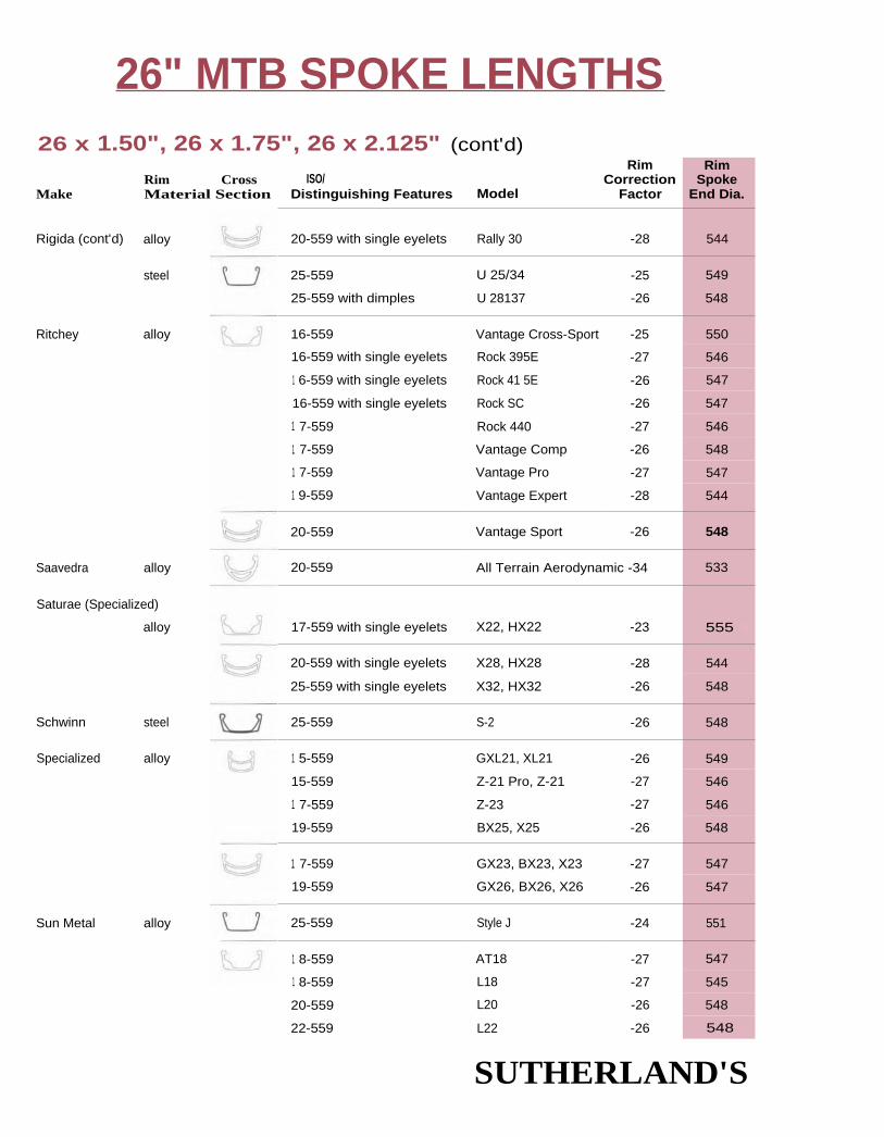
Rim CrossMake Material Section
Rigida (cont'd) alloy
steel
Ritchey alloy
Saturae (Specialized)
alloy
Schwinn steel
Specialized alloy
Sun Metal alloy
Saavedra alloy
26" MTB SPOKE LENGTHS26 x 1.50", 26 x 1.75", 26 x 2.125" (cont'd)
ISO/Distinguishing Features Model
RimCorrection
Factor
RimSpoke
End Dia.
20-559 with single eyelets Rally 30 -28 544
25-559 U 25/34 -25 549
25-559 with dimples U 28137 -26 548
16-559 Vantage Cross-Sport -25 550
16-559 with single eyelets Rock 395E -27 546
1 6-559 with single eyelets Rock 41 5E -26 547
16-559 with single eyelets Rock SC -26 547
1 7-559 Rock 440 -27 546
1 7-559 Vantage Comp -26 548
1 7-559 Vantage Pro -27 547
1 9-559 Vantage Expert -28 544
20-559 Vantage Sport -26 548
20-559 All Terrain Aerodynamic -34 533
17-559 with single eyelets X22, HX22 -23 555 I
20-559 with single eyelets X28, HX28 -28 544
25-559 with single eyelets X32, HX32 -26 548
25-559 S-2 -26 548
1 5-559 GXL21, XL21 -26 549
15-559 Z-21 Pro, Z-21 -27 546
1 7-559 Z-23 -27 546
19-559 BX25, X25 -26 548
1 7-559 GX23, BX23, X23 -27 547
19-559 GX26, BX26, X26 -26 547
25-559 Style J -24 551
1 8-559 AT18 -27 547
1 8-559 L18 -27 545
20-559 L20 -26 548
22-559 L22 -26 548 a
SUTHERLAND'S

Rim Cross ISO/Make Material Section Distinguishing Features
Sun Metal alloy
(cont'd)
steel
Torelli alloy
Ukai—see similar Araya model
25-559
25-559
25-559 with single eyelets
13 -559 with single eyelets
1 5-559
15-559 with single eyelets
1 6-559
16-559
1 6-559
1 7-559 with single eyelets
19-559
20-559
20-559
14-559
14-559
1 4-559 with single eyelets
17-559 with single eyelets
25-559
27-559
1 6-559 with double eyelets
1 5-559 with single eyelets
Velocity alloy 1 6-559
13-559
14-559
15-559
1 9-559
19-559
26" MTB SPOKE LENGTHS26 x 1.50", 26 x 1.75", 26 x 2.125" (cont'd)
Model
Rim RimCorrection Spoke
Factor End Dia.
L25 -25 550
Style I -25 549
M25 -25 550
M13L -26 549
CR161I -26 549
CRE16/CRT1611 -26 548
C16 -26 548
CR16 -26 547
CRT16 -26 549
CR18 -26 548
CR20 -28 545
Chinook C20 -27 546
Rhyno SST -29 541
M14A '91 & later -30 539
M14A pre '91 -28 543
ME14A -33 534
CR17A -28 545
Style M -26 548
Style N -25 550
Blaster -27 545
Rocket -26 547
Twin Hollow -26 549
Aero -33 534
Arrowhead -33 534
K-525 -31 539
Aero Heat AT -32 536
Triple V -26 547
.
SUTHERLAND'S

alloy
Wilderness Trail Bikes
alloy
Wolber/Super Champion
alloy
26" MTB SPOKE LENGTHS26 x 1.50", 26 x 1.75", 26 x 2.125" (cont'd)
Rim RimRim Cross ISO/ Correction Spoke
Make Material Section Distinguishing Features Model Factor End Dia
Weinmann—(old reference numbers in parentheses)
22-559 with single eyelets (522 X) -24 553
25-559 with single eyelets 2225 (425X) -24 552
25-559 with single eyelets 2225-1 (525X) -23 553
17-559 217 -25 550
17-559 BCX-3 -24 553
1 8-559 BCX-1 -23 554
1 8-559 BCX-2 -23 554
20-559 (420) -25 549
20-559 4019 -26 547
20-559 2219 (120) -25 549
21-559 2121 -25 551
22-559 (122B) -26 549
25-559 2125 -25 551
25-559 with dimples 525/431 -26 547
25-559 with eyelets 525/431 -26 548
18-559 BCX Red Label -27 546
1 8-559 BCX Blue Label -27 546
1 9-559 ZAC 19 -28 545
1 9-559 2419 -17 546
20-559 with double eyelets 2421 (921) -26 548
17-559 with reinforcement Power Beam -28 545
17-559 with single eyelets Speedmaster 2 -27 547
1 7-559 with single eyelets Speedmaster - 23mm -25 549
1 9-559 with single eyelets Speedmaster - 25mm -25 550
14-559 AT 15 -25 551
1 6-559 AT 18 -25 550
27-559 Canyon -26 548
1 9-559 AT 20 -27 546
SUTHERLAND'S

van Schothorst alloy
steel
Weinmann alloy
Wilderness Trail Bikes
alloy
alloyRigida
CrossSection
RimSpoke
End Dia.
548
105_5547
4
548
547
548
548
547
539539
547
545
541
48
545
544
541
545
546
543
545
548
26" MTB SPOKE LENGTHS26x 1.50", 26 x 1.75", 26 x 2.125"
RimMake Material
Alesa alloy
All Weather Sportsalloy
Araya alloy
Breezer/Ukai alloy
150/Distinguishing Features Model
17-559 with double eyelets 9017
21-559 with double eyelets 6017
41-559 44-Magnum
1 3-559 RM-14
20-559 VP-20
17-559 with double eyelets TM-810F
1 8-559 with double eyelets RM-910DH
26
-26
1 6-559 with inner web holes Backdraft -26
RimCorrection
Factor
26
-26
23
-26
-26
Campagnolo alloy
HED carbon fiberalloy
Matrix alloy
Mavic alloy
1 4-559 Atek -29
1 6-559 Stheno -30
1 6-559 with single eyelets Arkos -27
1 7-559* X-Country -28
20-559* Downhill -29
1 3-559 with double eyelets Single Track Pro -26
22-559 with double eyelets 281 -28
20-559 AS26F -26
1 8-559 Laser -28
1 6-559 Turbo 900 -30
1 7-559 Turbo 9 -28
21-559 AS 28 -27
25-559 US 34 -28
1 9-559 2719 -28
1 7-559 Power Beam** -27
1 7-559 Power Beam*** -26
*needs hex head nipples and wrench to true. * *'94-'95 (0D=571.5mm) "* 36 hole after 5/95 (OD=574.5mm)
SUTHERLAND'S

26" MTB SPOKE LENGTHS
SUTHERLAND'S

CONTENTS
A•t°717126" Other Rims
SPOKELENGTH
11
Step 2: 26" Rims
Approximate dimensions ....... 72
Calculating .............................. 72
Differences in hubs ................. 72
Right rear hub
spoke length ....................... 72
26" spoke lengthcharts .................................. 73
Step 3: 26" Rims
identifying rims ........................ 74
26" ri m correction factorsclinchers ........................ 74-77
tubulars ......................... 78-79
additions 8/95 ...................... 80a
SUTHERLAND'S

26" OTHER SPOKE LENGTHS
2nd Step of 3 steps26", 700D and 650 RimsCount the number of holes in the hub and
decide on a spoking pattern, i.e., 4-cross, 3-cross(4X, 3X) etc. Find the length listed for that
combination in the huh flange diameter catego-
ry selected in step 1. Write down the length.
For the right rear of multi-speed freewheel hubssubtract 2mm. (See below for details.)
Adjustments will also be needed for hubs that
are different from the specifications below.
26" Example One: Shimano Dura-Acefront hub with 32 holes. Look at the40mm hub flange diameter table. For 3Xwheel write down the length 293mm.
26" Example Two: Mavic 500 rear hub with36 holes. On the 44.5mm table a 3X wheelindicates a length of 290mm for the left side.For the right side use 288 mm.
The tables on the facing page will give you a length for the theoretical rim diameter of a 600mm
ri m. Step 3 (rim correction factor) will adjust these lengths for the exact rim you have.
Approximate DimensionsThe following hub dimensions were used for the tables on the opposite page. They are the
approximate dimensions for road hike front hubs and the left rear of a road bike rear hub.
Hub center to flange center - 35mmSpoke hole diameter - 2.6mmSpoke seating and stretch - 0.4mm
Differences in HubsMany hubs differ from the hub dimensionslisted above so adjustments may need to bemade as follows:
I !Lib center to flange center - a 1 mm differ-
ence will make a 0.1mm difference in final
spoke length.
Spoke hole size – a 0.2111111 difference will make a 0.1 mm difference in the final spoke length. En
practice this is usually not enough difference to matter.
Right Rear Hub Spoke LengthMost right rear road hubs require a shorter spoke. How much
shorter varies. Many hubs have a huh center to flange centeron the right rear of 20mm. This is a 1Sm m difference from the
tables. Using the guidelines for differences in hub center toFlange dimensions, subtract 1.5mm for the right rear spokes.
This is usually rounded up to 2mm.
3rd Step go to page 11-74
SUTHERLAND'S
26" Example Three: A Sachs jet coasterbrake with a 25mm hub center to flangecenter is 10mm narrower than the dimen-sions these tables are based on. Multiplying10mm by 0.1mm you get l mm. Subtract1mm to the final spoke length.
These combinationshave the same spokelength:
I 1 6 hole 1X = 32 hole 2X20 hole 2X = 40 hole 4X24 hole 2X = 48 hole 4X

26" SPOKE LENGTHS
31 mm Flange Diameter 34mm Flange Diameter
48
5X 4X 3X 2X 1 x radial
48
5X 4X 3X 2X 1 X radial
40 40 296 291 287* 284* 283*
36 298 293 289* 286* 285* 36 298 292 288* 285* 283*
32 301 295 290 286* 285* 32 300 294 289 285* 283*
28 297 291 287* 285* 28 297 290 285* 283*
24 293 287* 285* 24 292 286* 283*
40mm Flange Diameter 44.5 mm Flange Diameter
4840363228
5X 4X 3X 2X 1 X radial
4840363228
5X 4X 3X 2X 1 X radial
296 291295298301
287289291293297
283*285*285*287288
281*282*282*282*283*
280*280*280*280*280*
295 290294
297301
285288290293296
281*283*284*285287
279*279*280*280*281*
278*278*278*278*278*
48mm Flange Diameter 58mm Flange Diameter
4840363228
5X 4X 3X 2X 1 X radial
4840363228
5X 4X 3X 2X 1X radial
295 289294297
284287289292296
280*281*283*284286
277*278*278*278*279*
277*277*277*277*277*
294 287293297
281284287291295
276*278*279*281283
273*273*273*274*275*
272*272*272*272*272*
63mm Flange Diameter 67mm Flange Diameter
4840363228
5X 4X 3X 2X 1X radial
4840363228
5X 4X 3X 2X 1X radial
294 286292297
279283286290295
274*276*277*279282
270*271*271*272*273*
269*269*269*269*269*
294 285292
296
278282
285289295
272*274*276278281
268*269*269*270*271*
267*267*267*267*267*
90mm Flange Diameter 102.5_mm Flange Diameter
5X 4X 3X 2X 1X radial 5X 4X 3X 2X l x radial
48 292 281 271 263* 257* 256* 48 278 267 258* 252* 250*
40 290 276 266* 258* 256* 40 274 261* 252* 250*
36 296 281 268* 259* 256* 36 278 263* 253* 250*
32 286 271 260* 256* 32 285 267 254* 250*
28 294 275 261* 256*
* Hubs using these combinations must match the diameter category exactly for accurate
results. (See drawings and text on page 11-4.)
SUTHERLAND'S

Rim with Rim withsingle eyelet double eyelet
RimSpok
End Dia.
P591
591
589
590
684590
586
590
26" OTHER SPOKE LENGTHS
3rd Step of 3 steps26", 700D and 650 RimsFind the rim in the tables below. Subtract the
ri m correction factor from the number you
came up with in step 2. The answer is the final
length of the spoke you need.
Identifying RimsRims are grouped in descending order by bead
seat diameters. ISO rim markings are used in
these tables to help distinguish the various
models of ri ms. For an explanation of these
markings, (see page 12-3.)
The rim cross section drawings are not exact
representations of each ri m.
Unless noted otherwise, rims listed do not
have eyelets or dimples.
Dura-Ace front hub26" Example One:
with a Sun Metal 26 x 13/4 ME14A ri m. Rimcorrection factor for this rim is -27. Thelength from step 2 is 293. 293 minus 27 is266. 266 is the final length.
26" Example Two: Mavic rear hub with aMavic 650C Open 4 ri m. The rim correc-tion factor for this rim is -23. The lengthsfrom step 2 are 290 for the left side and288 for the right. 290 minus 23 is 267 and288 minus 23 is 265. 267 and 265 are thefinal lengths.
26" x 1 1/4", 26" x 1 3/8 " , EA1, 5-5, 5-6
Rim Cross ISO/Make Material Section Distinguishing Features Model
RimCorrection
Factor
Alesa—see Weinmann (use old reference numbers)
Araya alloy 19-597 16A(3) -5
steel L..,916-597 5H -5
Rigida steel L2 1 7-597 Deco 30 -6
20-597 Deco 35 -5
Schwinn steel 22-597 5-5 (26x1-3/8) -8
20-597 S-6 (26x1-1/4) -5
Sturmey-Archer steel 20-597 EA 23.5 - 5
Sun Metal alloy 1 3-597 with single eyelets Mistral M1311 -7
Weinmann—(old reference numbers in parentheses)
alloy 1:(1.21 16-597 2115 (716, 416, 116) -5
SUTHERLAND'S

RimSpoke
End Dia.
584
583
584
583
583
581
588
584
582
15 78
578
5
578
583
583
579
582
578
579
570
576
578
581
26" OTHER SPOKE LENGTHS 26" x 1 3/8", EA3, 650A
MakeRim CrossMaterial Section
ISO/Distinguishing Features Model
RimCorrection
Factor
Alesa—see Weinmann (use old reference numbers)
Ambrosio alloy rL 20-590 -8
Araya alloy L=f5 1 6-590 16A(5) -9
1 7-590 18 -8
20-590 1 5 -9
steel (11_2 20-590 5 -9
CMC steel L.2) 18-590 -9
Femco steel (11.2 18-590 5 -6
M.O. Mfg. steel L2) 20-590 -8
Mavic alloy 1 3-590 with double eyelets Module E2 -9
15-590 with single eyelets Module 3 -11
19-590 with double eyelets Module 4 -11
Raleigh steel 0=1/411 22-590 R 23.0 -11
Rigida steel 17-590 Deco 30 -8
21-590 Deco 35 -8
Schwinn—see 597mm Bead Seat
Sturmey-Archer steel 11...1) 24-590 R 23.0 -10
1...451 20-590 EA 210 -9
Sun Metal alloy 20-590 L20 -11
20-590 with single eyelets M20 -10
14-590 M14A -15
19-590 CR20 -12
19-590 CR20 -11
steel IL2 21-590 Style K -10
SUTHERLAND'S

RimSpoke
End Dia.
582
585
583
580
580
581
RimSpoke
End Dia.
574
570
RimSpoke
End Dia.
576
573411
573
572
572
572
576
577
576
26" OTHER SPOKE LENGTHS 26" x 1 3/8", EA3, 650A (contd)
RimRim Cross 150/ Correction
Make Material Section Distinguishing Features Model Factor
Weinmann—(old reference numbers in parentheses)
alloy J 16-590 2115 (716, 416, 116) -9
16-590 with single eyelets (Al25) -8
20-590 2119, (120) -9
20-590 (420, 420R) -10
R 20-590 2120 -10
RimRim Cross 150/ CorrectionMaterial Section Distinguishing Features Model Factor
700D
Make
Araya alloy 19-587 RM 20 -13
Sun Metal alloy 61 15-587 CR16 -15
26 x 1 1/2", 650BRim
Rim Cross 150/ CorrectionMake Material Section Distinguishing Features Model Factor
Alesa—see Weinmann (use old reference numbers)
Araya alloy 20-584
20-584
15 -12
ADX-8W -14
Mavic allay 15-584 with double eyelets Module 3D
15-584 with single eyelets Module 3
9-584 with double eyelets Module 4
Rigida alloy 1 5-584 with single eyelets AL 15/21
16-584 with single eyelets AL 16/22
L.2 21-584 Deco 35
Wolber/Super Champion
alloy L.1 17-584 with single eyelets Model 58 -12
SUTHERLAND'S
fl
-14
-14
-14
-14
-12
-12

26" OTHER SPOKE LENGTHS 26 x 1 3/4 ", 650C
MakeRimMaterial
CrossSection
ISO/Distinguishing Features Model
RimCorrection
Factor
Araya alloy 13-571 Super Aero 530 -36
Campagnolo alloy 1 3-571 with double eyelets Omega 19 -22
13-571 with rim washers Shamal -33
Euro-Asia alloy 1 3-5 71 Arrow -34
Mavic alloy 13 -571 with double eyelets MA 40 -20
k_ 5 13 -571 with single eyelets Open 4 -23
Schwinn steel L2 25-571 5-7 -19
Sun Metal alloy 13-571 with double eyelets Ml 3L -20
12-571 fv114A -24
13-571 with single eyelets ME14A -27
14-571 Venus -30
Velocity alloyV-.77
14-571 Arrowhead -27
RimSpoke
End Dia.
52
555
533
531
561
554
562
561
1 552
P 546
540
6 545
SUTHERLAND'S

RimSpoke
End Dia.
582
572 "I
RimSpoke
End Dia.
533 0577
6
1587.
563
57
RimSpoke
End Dia.
5581
Rim.Spoke
End Dia.
559
561
566
•
26" OTHER SPOKE LENGTHS 26" Sew-ups (650) - 597mm outside diameter
RimRim Cross ISO/ Correction
Make Material Section Distinguishing Features Model Factor
Nisi alloy 19 with rim washer Unspecified -9
Weinmann alloy C'''-,___ I 26 950 Cycloball -14
26" Sew-ups (650) - 594mm outside diameter
MakeRim Cross ISO/Material Section Distinguishing Features Model
RimCorrection
Factor
Campagnolo alloy 19 with rim washers,
deep aero Shamal
Mavic alloy 1 8.5 with double eyelets CX-18
-33
-11
19 with double eyelets Mach 2 -21
19 with single eyelets Mach 2 CD
20 with double eyelets G.L. 330
-18
-12
26" Sew-ups - 587mm outside diameter
Make
RimRim Cross ISO/ CorrectionMaterial Section Distinguishing Features Model Factor
Mavic alloy 19 with double eyelets Mach 2 CD 2 -21
26" Sew-ups - 584mm outside diameter
Make
RimRim Cross ISO/ CorrectionMaterial Section Distinguishing Features Model Factor
Araya alloy 0 1 9 ADX-4 (Aero 4) -21
Nisi alloy U 19 with single eyelets Laser -20
Sideral alloy U 19 with eyelets 2001 Prof. Profile LM - 17
Zipp carbon fiber 20 deep aero section 400 -59
SUTHERLAND'S

alloy 1 6 with special
nipples and washer Unspecified Model -1 5
Assos
569
26" OTHER SPOKE LENGTHS 26" Sew-ups - 582mm outside diameter
Rim Cross ISO/Make Material Section Distinguishing Features Model
Fiamme alloy 18.5 Speedy
Saavedra alloy 1 9 with rim washer Turbo
Sun Metal alloy U 1 7 M17A
19 M19All
17 Mistral M17A
1 9 Mistral M19A
21 with double eyelets Mistral M20B
Wolber/Super Champion
alloy 17.5 Profil 18
1 9 Profit 20
RimCorrection
Factor
RimSpoke
End Dia.
1 6 568
-21 558
-20 560
-24 552
-20 560
-24 552
-19 562
-21 559
-25 551
26" Sew-ups - 579mm outside diameterRim Rim
Rim Cross ISO/ Correction SpokeMake Material Section Distinguishing Features Model Factor End Dia.
26" Sew-ups - 572mm outside diameterRim
Rim Cross ISO/ CorrectionMake Material Section Distinguishing Features Model Factor
RimSpoke
End Dia.
Mavic alloy 28 with double eyelets TT B1 CD -26 548
SUTHERLAND'S

SPOKE LENGTHS
SUTHERLAND'S

26" OTHER SPOKE LENGTHS
Rim Rijn150/ Correction SpokDistinguishing Features Model Factor End Di
18-590 AS 25 -10 580MIME
Rim Rim150/ Correction SpokeDistinguishing Features Model Factor End Dia.
1 6-583 RM 17 -13 573
19-583 RM-20 -13 574
15-583 CR16 -15 570
Rim RimISO/ Correction SpokDistinguishing Features Model Factor End D
13-571* Jet -24 552
12-571 with single eyelets 2001 Professional --23Argentina
26 x 13/4", 650A, EA3
Rim CrossMake Material Section
van Schothorst alloy
700D
Rim CrossMake Material Section
Araya alloy'
Sun Metal alloy r.,,7d
26" x 1 3/4", 650C
Rim CrossMake Material Section
HED carbon fiber/ -alloy
Sideral alloy
*needs hex head nipples and wrench to true.
SUTHERLAND'S

RimSpokeal
End Di
569
5fildi
26" MTB SPOKE LENGTHS 26" Sew-ups - 586mm outside diameter
RimRim Cross ISO/ Correction
Make Material Section Distinguishing Features Model Factor
26" Sew-ups - 585mm outside diameter
Campagnolo alloy 20 Sigma -15
20 with double eyelets Sigma Crono -15
Make
Zipp
RimRim Cross ISO/ CorrectionMaterial Section Distinguishing Features Model Factor
carbon fiber 1 9 310
20 400
RimSpoke
End Dia.
519
481
-41 *
-59**
26" Sew-ups - 583mm outside diameterRim
Rim Cross ISO/ CorrectionMake Material Section Distinguishing Features Model Factor
Araya alloy 19 SA-230S Super Aero -34
26" Sew-ups - 582mm outside diameterRim
Rim Cross ISO/ CorrectionMake Material Section Distinguishing Features Model Factor
RimSpoke
End Dia.
Rim IISpoke
End Dia.
532
HED carbon fiber 19*** Jetalloy
Sun Metal alloy L.. . 21 with double eyelets M2013
Wolber alloy C / 25 TR1
-24 552
-21 558
-24 552
26" Sew-ups - 572mm outside diameterRim
Rim Cross 150/ CorrectionMake Material Section Distinguishing Features Model Factor
Wolber alloy 25 TR1 -24
RimSpoke
End Dia.E552
* for more consistant results use 24" tables (page 11-83) with -11 rim correction factor.
** for more consistant results use 24" tables (page 11-83) with -30 rim correction factor.
*" use hex head nipples and wrench to true.
SUTHERLAND'S

10 2X IX raasl SA t; 1a n 1a
106 /02 29.R. Mr 110 101 00 X, 7111.110 109 19?211, 1111 101 299- NV
/0911.r, 1.
101 2911 11 IME 100 NS.'111 101 is, 291 1 31" 100 2/11
viang. Charnew 58, ",ohip Gamow• 4X 1X 21 IX mils SX 4/1 34 10 "1
190 2w MS' 292° I.. II109 102 tor 204' sa
7.
7 2299 42 1. .0 11
• IPII I 101 Mi . 290 1 .1I
Ine 102 PM 111,
1011 2129 Ms 284.rav
ONI 290 2812-110 29/ 11•1•
63 Damese 67.en Ow/al,40 1.1 1R ruiei SP 41 14
2191 201 axe IR Icy 11, 2,-_S11 21"41 '94' 10
CONTENTS
11Nk 24" andBelow Rims
SPOKELENGTH
Step 2: 24/22" RimsApproximate dimensions ....... 82
Calculating ............................... 82
Differences in hubs ................. 82
Right rear hubspoke length ....................... 82
24/22" spoke length charts .. 83
Step 3: 24/22" RimsIdentifying rims ........................ 84
24/22" ri m correction factorsclinchers ........................ 84-91
tubulars ......................... 89-91
Step 2: 20 1 ' RimsApproximate dimensions ....... 92
Calculating ............................... 92
Differences in hubs ................. 92
22" spoke length charts ....... 93
Step 3: 20" RimsIdentifying rims ........................ 94
20" rim correction factorsclinchers ........................ 94-98tubulars ............................... 98
Step 2: 18/17" RimsApproximate dimensions ...... 99
Differences in hubs ................. 99
18/17" spoke length charts . 99
Step 3: 18/17" Rims18/17" rim correction factors
clinchers ........................... 1 00tubulars ............................ 1 00
Step 2: 16" RimsApproximate dimensions ..... 101
Differences in hubs ............... 1 01
16" spoke length charts ..... 101
Step 3: 16" Rims16" ri m correction factors
clinchers ................... 1 02-103tubulars ............................ 1 03
Step 2: 14" RimsApproximate dimensions .....104
Differences in hubs ............... 1 04
14" spoke length charts .... 104
Step 3: 14" Rims14" ri m correction factors
clinchers ........................... 1 05tubulars ............................ 1 05
Step 2: 12" RimsApproximate dimensions .....106
Differences in hubs ............... 1 06
12" spoke length charts ..... 106
12" ri m correction factorsclinchers ........................... 106
Step 2: 10" RimsApproximate dimensions .... 107
Differences in hubs ............... 1 07
10" ri m correction factors
clinchers ........................... 1 07SUTHERLAND'S

These combinationshave the same spokelength:
1 6 hole 1X20 hole 1X20 hole 2X24 hole 1 X24 hole 2X
= 32 hole 2X= 40 hole 2X= 40 hole 4X= 48 hole 2X= 48 hole 4X
24" & 22"SPOKE LENGTHS 2nd Step of 3 steps24", 600 and 550 RimsCount the number of holes in the hub and
decide on a spoking pattern, Le., 4-cross, 3-cross
14X, 3X) etc. Find the length listed for that
combination in the hub flange diameter catego-
ry selected in step Write down the length.
For the right rear of multi-speed freewheel hubs
subtract 2mm, (See below for details.)
Adjustments will also be needed for hubs that
are different from the specifications below.
24" Example One: Shimano aura-Acefront hub with 32 holes. Look at the40mm hub flange diameter table. For a 3Xwheel write down the length 264mm.
24" Example Two: Mavic 500 rear hubwith 36 holes. On the 44.5mm table a 3Xwheel indicates a length of 260rnm for theleft side. For the right side use 258mm.
The tables on the facing page will give you a length for the theoretical rim diameter of a 540mm
ri m. Step 3 (rim correction factor) will adjust these lengths for the exact rim you have.
Approximate DimensionsThe following hub dimensions were used for the tables on the opposite page. They are the
approximate dimensions for road bike front hubs and the left rear of a road bike rear hub.
Huh center to flange center - 35mm
Spoke hole diameter - 2.6mm
Spoke seating and stretch - 0.4mm
Differences in HubsMany hubs differ from the hub dimensions
listed above so adjustments may need to be
made as follows:
Hub center to flange center —a 1mm difference
will make a 0.1mm difference in final
spoke length.
24" Example Three: A Sachs Jet coasterbrake with a 25mm hub center to flangecenter is 10mm narrower than the dimen-sions these tables are based on. Multiplying10mm by 0.1mm you get 1 mm. Subtract1 mm to the final spoke length.
Spoke hole size — a 0.2mm difference will make a 0.1mm difference in t he final spoke length. in
practice this is usually not enough difference to matter.
Right Rear Hub Spoke LengthMust right rear road hubs require a shorter spoke. How much
shorter varies. Many hubs have a hub center to flange center
on the right rear of 20mm. This is a 15mm difference from the
tables. Using the guidelines for differences in hub center to
flange dimensions, subtract 1.5mm for the right rear spokes.
This is usually rounded up to 2mm.
3rd Step go to page 11-84
SUTHERLAND'S

24" & 22" SPOKE LENGTHS 31 mm Flange Diameter 34mm Flange Diameter
48
4X 3X 2X 1X radial
48
4X 3X 2X 1X radial
40 40 266 261 257* 255* 254*36 268 263 259* 256* 255* 36 268 263 258* 255* 254*32 271 265 260 256* 255* 32 265 259 255* 254*28 268 261 257* 255* 28 267 260 255* 254*24 271 263 257* 255* 24 263 256* 254*
40mm Flange Diameter 44.5 mm Flange Diameter4X 3X 2X 1X radial 4X 3X 2X 1X radial
48 261 257 254* 251* 251* 48 260 255 252* 249* 249*40 265 259 255* 252* 251* 40 265 258 253* 250* 249*36 268 MI 256* 252* 251* 36 268 260 254* 250* 249*32 26411B7 252* 251* 32 263 255 250* 249*28 267 259 253* 251* 28 267 257 251* 249*24 261 254* 251* 24 260 252* 249*
48mm Flange Diameter 58mm Flange Diameter4X 3X 2X 1X radial 4X 3X 2X 1 X radial
48 259 254 250* 248* 247* 48 257 251 246* 243* 242*40 264 257 252* 248* 247* 40 263 255 248* 243* 242*36 267 259 253* 248* 247* 36 267 257 249* 244* 242*32 262 254 249* 247* 32 261 251 244* 242*28 266 256 249* 247* 28 266 254 245* 242*24 259 250* 247* 24 257 246* 242*
63 r l m Flange Diameter 67i i m Flange Diameter4X 3X 2X 1 X radial 4X 3X 2X 1X radial
48 256 249 244* 241* 239* 48 256 248 242* 239* 237*40 263 253 246* 241* 239* 40 262 252 244* 239* 237*36 267 256 247* 241* 239* 36 267 256 246* 240* 237*32 260 249 242* 239* 32 260 248 240* 237*28 265 252 243* 239* 28 265 251 241* 237*24 256 244* 239* 24 256 242* 237*
90mm
484036322824
Flange Diameter4X 3X 2X l x radial
484036322824
1 02.5mrn Flange Diameter4X 3X 2X 1 X radial
251260266
241247251257264
233*236*238*241245251
228*229*229*230*231*233*
226*226*226*226*226*226*
249 237244249256264
228*231*234*237242249
222*223*224*225*226*228*
220*220*220*220*220*220*
* Hubs using these combinations must match t he diameter category exactly for accurateresults. (See drawings and text on page 11-4.)
SUTHERLAND'S

Rim Cross 150/Material Section Distinguishing Features
steel HB 557 x 17
Rim RimCorrection Spoke
Factor End Dia.
0 539
Make
Sun Metal
Model
Style H
24" ST 22" SPOKE LENGTHS
3rd Step of 3 steps24", 22", 600 and 550 RimsFind the rim in the tables below. Subtract the
rim correction factor from the number you
came up with in step 2. The answer is the final
length of the spoke you need.
Identifying RimsRims are grouped in descending order by bead
seat diameters. ISO rim markings are used in
these tables to help distinguish the various mod-
els of rims. (See page 12-3 for an explanationof these markings.)
The run cross section drawings are not exact representations of each rim.
Unless noted otherwise, rims listed do not have eyelets or dimples.
Be sure to measure the outside diameter before building a wheel to confirm that you
have the correct category of rim. Unlike 27 x 1 1/4 and 27 x 1'/8 rims which have the same
bead seat diameter, 24 x 11/4 and 24 x 11/4 do not have the same bead seat diameter.
24 x 1.25", 24 x1.375"
24" Example One: Dura-Ace front hubwith an Araya 24 x 1 1/4 20A ri m. The rimcorrection factor for this rim is -3. Thelength from step 2 is 264. 264 minus 3 is261. 261 is the final length.
24" Example Two: Mavic rear hub with aSun Metal 24 x M17. The rim correc-tion factor for this rim is -5. The lengthsfrom step 2 are 260 for the left side and258 for the right. 260 minus 5 is 255 and258 minus 5 is 253. 255 and 253 are thefinal lengths.
-44
24 x Phi", Schwinn 5-5, S-6 (outside rim diameter approx. 559mm)
MakeRimMaterial
CrossSection
ISO/Distinguishing Features Model
RimCorrection
Factor
RimSpoke
End Dia.
Araya alloy 1 3-546 with double eyelets 20A -3 534
16-546 1 6(5) -1 538'
Femco steel f9 18-547 5 0 539
Schwinn steel a,1/4...p0 22-546 S-5 (24 x 1-3/8) -4 532
iL.2) 20-546 5-6 (24 x 1-1/4) 538
SUTHERLAND'S
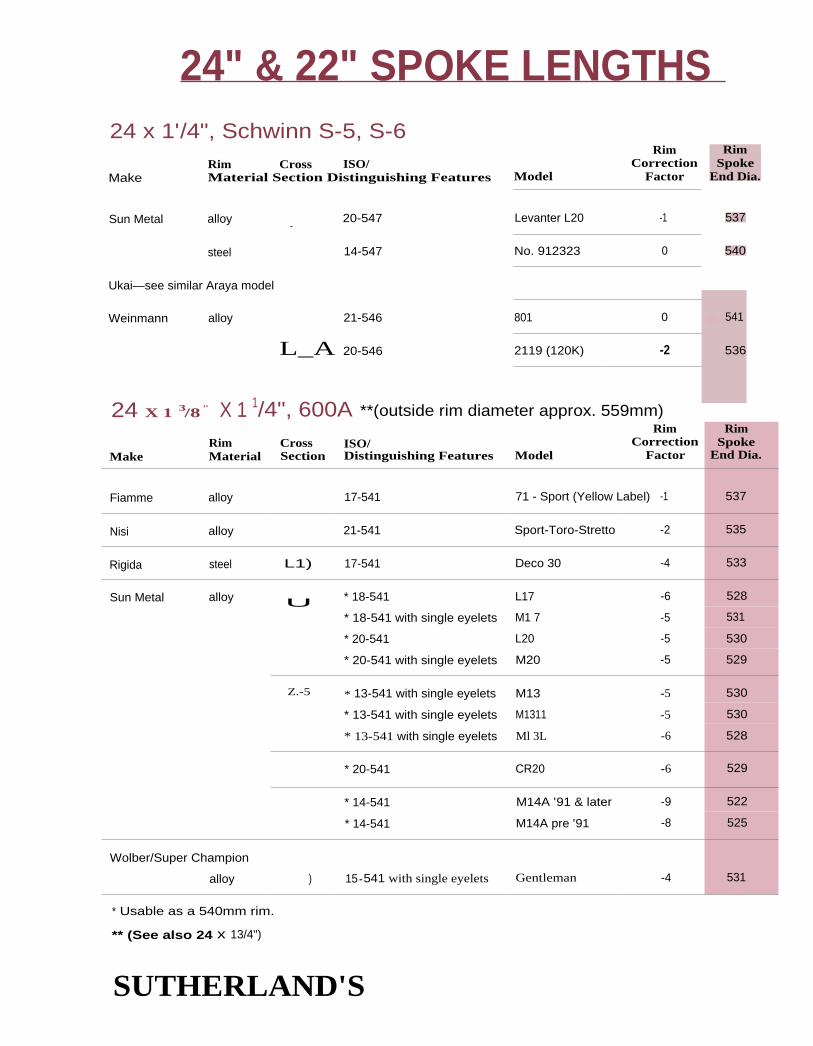
537
540
L, 541
536
24" & 22" SPOKE LENGTHS 24 x 1'/4", Schwinn S-5, S-6
Rim Cross ISO/Make Material Section Distinguishing Features Model
RimCorrection
Factor
Levanter L20 -1
No. 912323 0
801 0
2119 (120K) -2
RimSpoke
End Dia.
Sun Metal alloy _ 20-547
steel 14-547
Ukai—see similar Araya model
Weinmann alloy 21-546
L_A 20-546
24 X 1 3/8 " X 1 1/4", 600A **(outside rim diameter approx. 559mm)
RimMake Material
CrossSection
ISO/Distinguishing Features Model
RimCorrection
Factor
RimSpoke
End Dia.
Fiamme alloy 17-541 71 - Sport (Yellow Label) -1 537
Nisi alloy 21-541 Sport-Toro-Stretto -2 535
Rigida steel L1) 17-541 Deco 30 -4 533
Sun Metal alloy U * 18-541 L17 -6 528
* 18-541 with single eyelets M1 7 -5 531
* 20-541 L20 -5 530
* 20-541 with single eyelets M20 -5 529
Z.-5 * 13-541 with single eyelets M13 -5 530
* 13-541 with single eyelets M1311 -5 530
* 13-541 with single eyelets Ml 3L -6 528
* 20-541 CR20 -6 529
* 14-541 M14A '91 & later -9 522
* 14-541 M14A pre '91 -8 525
Wolber/Super Champion
alloy ) 15 -541 with single eyelets Gentleman -4 531
* Usable as a 540mm rim.
** (See also 24 x 13/4")
SUTHERLAND'S

RimSpoke
End Dia.
530
532
532
532
526
531
532
532
527
531
529
530
527
528
530
*am530
530
RimSpoke
End Dia.
510
24" 67- 22" SPOKE LENGTHS24 x 1 3/8", (see also 24 x 1 3/8" x 1 1/2 " )
Rim Cross 150/Make Material Section Distinguishing Features Model
RimCorrection
Factor
Ambrosio alloy 14-540 Elite -5
Araya alloy 20-540 1 5 -4
steel 20-540 5 -4
CMC steel 18-540 -4
Mistral—see Sun Metal
Raleigh steel 22-540 R21.0 -7
Rigida steel L2 1 7-540 Deco 30 -4
20-540 Deco 35 -4
Schwinn—see 546mm Bead Seat Diameter
Sturmey-Archer steel 20-540...S EA 21.0 -4
Sun Metal alloy u 1 7-540 L17 -6
1 8-540 with single eyelets Ml 7 -5
20-540 L20 -6
20-540 with single eyelets M20 -5
1 6-540 CR16 -6
20-540 CR20 -6
steel Lag 20-540 Style K -5
Ukai—see similar Araya model
Weinmann—(old reference numbers in parentheses)
alloy 20-540 2120 -5
20-540 2119 (120K, 720K) -5
24 x 1 3/4", Schwinn S-7Rim
Rim Cross ISO/ CorrectionMake Material Section Distinguishing Features Model Factor
Schwinn steel L2) 25-521 S-7 -15
SUTHERLAND'S

alloy 20-507 with dimples Aero 7W (ADX-7W)
Z-Rimplastic 25-507
FL Benelux 3226-507alloy
ISO/Distinguishing Features Model
RimCorrection
Factor
RimSpoke
End Dia.
14-520 20A -15 509
1 4-520 SS-45 -14 512
12-520 with single eyelets 2001 Prof. Argentina -18 503
25-520 with single eyelets M25 -17 506
1 3-520 M13 -16 510
1 3-520 with single eyelets M1311 -15 510
1 3-520 with single eyelets Ml3L -15 510
14-520 M14A pre '91 -20 501
14-520 M14A '91 and later -19 502
14-520 with single eyelets ME14A -22 496
RimCorrection
Factor
RimSpoke
End Dia.
-20 II 500
-20 500
-28 484
-23 495
-22 496
-22 497
-22 496
-21 4495
-23 495
-22 496
-19 502
-19 501
24 x 1h/8"
Rim CrossMake Material Section
Araya alloy
i -, 5)
Sideral alloy -----5'\_i
Sun Meta alloy
alloy
24 x 1.50", 24 x 1.75", 24 x 2.125"
20-507 with dimples
25-507 with dimples
7X (N)
7X
20-507 w/ridges on the edges RM-20
25-507 w/ridges on the edges RM-25
steel C 7 25-507 7A
Kin-Lin alloy 24-507 with dimples 21 AL
Rigida alloy 25-507 AL 25/32
steel 9 25-507 U 25/34
28-507 with dimples U 28/37
Rim Cross ISO/Material Section Distinguishing Features ModelMake
A.C.S.
Ambrosio
Araya
24" & 22" SPOKE LENGTHS
SUTHERLAND'S
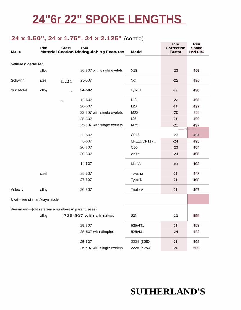
24"6r 22" SPOKE LENGTHS 24 x 1.50", 24 x 1.75", 24 x 2.125" (cont'd)
Saturae (Specialized)
alloy 20-507 with single eyelets
Schwinn steel L.21 25-507
Sun Metal alloy 7 24-507
V., 19-507
20-507
22-507 with single eyelets
25-507
25-507 with single eyelets
1 6-507
1 6-507
20-507
20-507
14-507
steel 25-507
27-507
Velocity alloy 20-507
Ukai—see similar Araya model
Weinmann—(old reference numbers in parentheses)
alloy I735-507 with dimples
25-507
25-507 with dimples
25-507
25-507 with single eyelets
Model
Rim RimCorrection Spoke
Factor End Dia.
X28 -23 495
S-2 -22 496
Type J -21 498
L18 -22 495
L20 -21 497
M22 -20 500
L25 -21 499
M25 -22 497—milib__
CR16 -23 494
CRE16/CRT1 611 -24 493
C20 -23 494
CR20 -24 495
M14A -24 493
Type M -21 498
Type N -21 498
Triple V -21 497
494S35 -23
525/431 -21 498
525/431 -24 492
2225 (525X) -21 498
2225 (525X) -20 500
Rim Cross 150/Make Material Section Distinguishing Features
SUTHERLAND'S
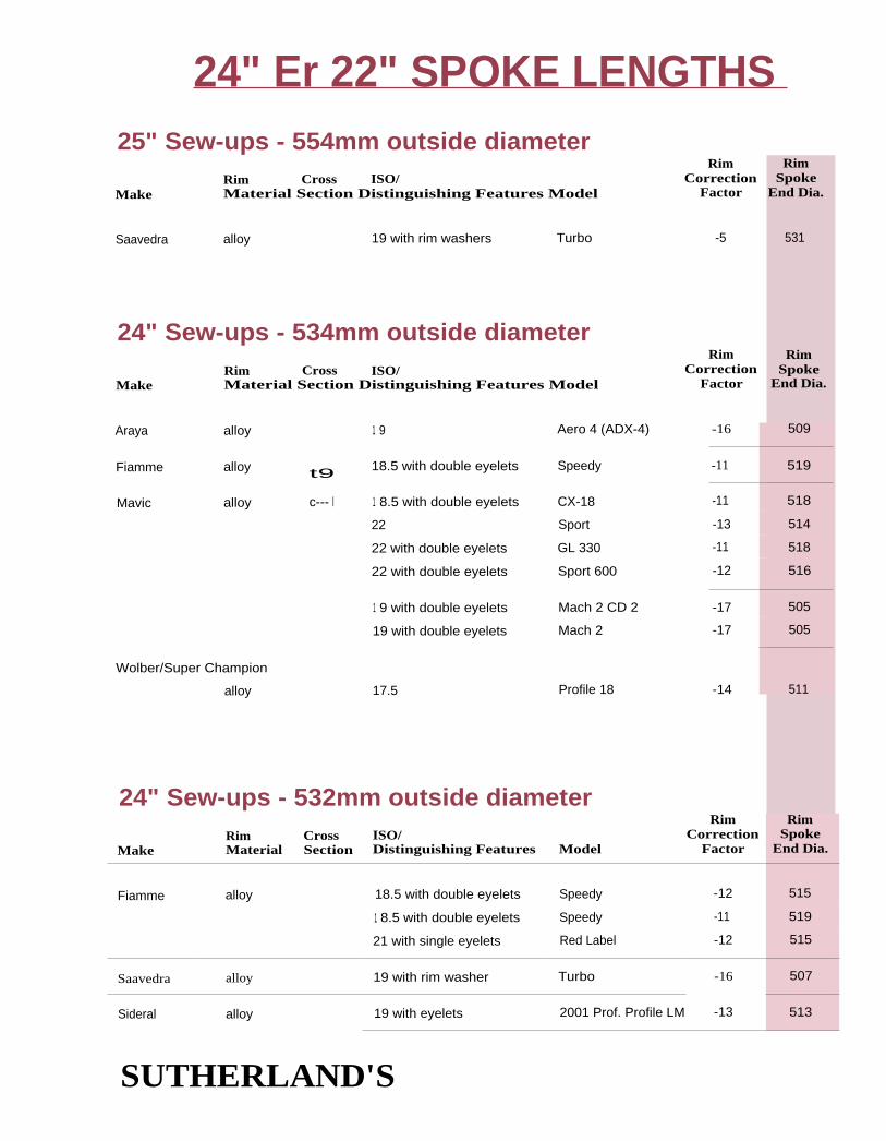
25" Sew-ups - 554mm outside diameterRim
Rim Cross ISO/ CorrectionMaterial Section Distinguishing Features Model FactorMake
RimSpoke
End Dia.
Saavedra alloy 19 with rim washers Turbo -5 531
24" Sew-ups - 534mm outside diameterRim
Rim Cross ISO/ CorrectionMake Material Section Distinguishing Features Model Factor
RimSpoke
End Dia.
Araya alloy 1 9 Aero 4 (ADX-4)
Fiamme alloy t9 18.5 with double eyelets Speedy
Mavic alloy c--- n 1 8.5 with double eyelets CX-18
22 Sport
22 with double eyelets GL 330
22 with double eyelets Sport 600
1 9 with double eyelets Mach 2 CD 2
19 with double eyelets Mach 2
Wolber/Super Champion
alloy 17.5 Profile 18
-16 509
-11 519
-11 518
-13 514
-11 518
-12 516
-17 505
-17 505
-14 511
24" Sew-ups - 532mm outside diameter
MakeRim CrossMaterial Section
ISO/Distinguishing Features Model
RimCorrection
Factor
RimSpoke
End Dia.
Fiamme alloy 18.5 with double eyelets Speedy -12 515
1 8.5 with double eyelets Speedy -11 519
21 with single eyelets Red Label -12 515
Saavedra alloy 19 with rim washer Turbo -16 507
Sideral alloy 19 with eyelets 2001 Prof. Profile LM -13 513
24" Er 22" SPOKE LENGTHS
SUTHERLAND'S

Assos alloy 16 with
special nipples and washer 16mm x 24 -11 518
RimSpoke
End Dia.
494
494
493
491
479M14A -3014-501
24" ST 22" SPOKE LENGTHS24" Sew-ups - 532mm outside diameter (cont'd)
Make
RimSpoke
End Dia.
RimRim Cross ISO/ CorrectionMaterial Section Distinguishing Features Model Factor
-15 511
-19 501
-19 501
-14 512
Sun Metal alloy C=1 17 M17A
19 M19AII
19 M19A
21 with double eyelets M2OB
24" Sew-ups - 527mm outside diameter
Make
RimSpoke
End Dia.
RimRim Cross ISO/ CorrectionMaterial Section Distinguishing Features Model Factor
22 x 3/8"Rim
Rim Cross ISO/ CorrectionMake Material Section Distinguishing Features Model Factor
Araya alloy 20-501 15 -23
steel L_27 20-501 5 -23
Sun Metal alloy 18-501 L17 -24
20-501 L20 -25
steel 15-501 No. 912213 -24
Weinmann—(old reference numbers in parentheses)
alloy L rj 20-501 2120 -24
20-501 2119 (120K) -24
493
111—492
492
SUTHERLAND'S

RimSpoke
End Dia.
483
483
RimSpoke
End Dia.
446
448
RimSpoke
End Dia.
466
24" El 22" SPOKE LENGTHS
RimRim Cross ISO/ CorrectionMaterial Section Distinguishing Features Model Factor
550A
Make
Gitane OEM steel iLag 20-490 -28
Rigida steel IL.c9 17-490 Deco 30 -28
22 x 1.50", 22 x 1.75 ", 22 x 2.125"Rim
Rim Cross BD/ CorrectionMake Material Section Distinguishing Features Model Factor
Araya steel 725-457 7A -47
CMC steel C Y24-457 -46
22" Sew-upsRim
Rim Cross ISO/ CorrectionMake Material Section Distinguishing Features Model Factor
Fiamme alloy -37
SUTHERLAND'S

20" Example One: GT BMX front hubwith a 35mm hub center to flange centeris 7mm wider than the dimensions thesetables are based on. Multiplying 7mm by0.12mm you get 0.84mm. Add 1 mm tothe spoke length.
These combinationshave the same spokelength:
1 6 hole 1X 32 hole 2X20 hole 1X 40 hole 2X20 hole 2X 40 hole 4X24 hole 1X 48 hole 2X24 hole 2X 48 hole 4X
20" SPOKE LENGTHS
2nd Step of 3 steps20" and 500 RimsCount the number of holes in the hub anddecide on a spoking pattern, i.e. 4-cross, 3-cross(4X, 3X) etc. Find the length listed for that com-bination in the hub diameter category selectedin step 1. Write down the length. Front hubflanges are often farther apart and generally needa 1 mm longer spoke, (see below for details).Adjustments will also be needed for hubs thatare different from the specifications below.
20" Example One: GT BMX front hubwith 32 holes. Look at the 40mm hubflange diameter table. For a 3X wheel218mm is the listed length. Add 1 mm forthe front hub. See differences in Hubsbelow. Write down 219mm.
20" Example Two: CT BMX rear hub with36 holes. On the 44.5mm table a 3Xwheel indicates a length of 215mm.
The tables on the facing page will give you a length for the theoretical rim diameter of a 450mm
ri m. Step 3 (rim correction factor) will adjust these lengths for the exact rim you have.
Approximate DimensionsThe following huh dimensions were used for the tables on the opposite page. They are theapproximate dimensions for a rear BMX hub or coaster brake.
Hub center to flange center - 28mm
Spoke hole diameter - 2.6mm
Spoke seating and stretch - 0.4mm
Differences in HubsMany hubs differ from the huh dimensionslisted above so adjustments may need to bemade as follows:
Ilub center to flange center --- a 1mm difference
will make a 0.12mm difference in final
spoke length.
Spoke hole size — a 0.2mm difference willmake a 0.1mm difference in the final spokelength. In practice this is usually not enoughdifference to matter.
3rd Step go to page 11-94
SUTHERLAND'S

220 216 212*223 217 212*
219 213*222 215
217220
209* 208*209* 208*210* 208*210* 208*211* 208*212* 208*
20" SPOKE LENGTHS 31 mm Flange Diameter
4X 3X 2X 1 X radial484036 224 219 215* 212* 211*32 227 221 215* 212* 211*28 223 217 212* 211*24 227 219 213* 211*20 222 214* 211*
40mm Flange Diameter
34mm Flange Diameter
4X 3X 2X 1 x radial
44.5mm Flange Diameter
48403632282420
4X 3X 2X 1 X radial 4X 3X 2X 1X radial
48 216 211 208* 206* 205* 48 215 210 206* 204* 203*40 220 214 209* 206* 205* 40 219 213 208* 204* 203*36 222 216 210* 207* 205* 36 222 215 209* 204* 203*32 218 211* 207* 205* 32 218 210 205* 203*28 221 213 207* 205* 28 221 212 205* 203*24 216 208* 205* 24 215 206* 203*
48mm Flange Diameter 58mm Flange Diameter
4X 3X 2X 1 x radial 4X 3X 2X 1 X radial
48 214 209 205* 202* 201* 48 212 206 201* 1 97* 196*40 219 212 206* 203* 201* 40 218 209 202* 198* 1 96*36 222 214 207* 203* 201* 36 222 212 204* 198* 1 96*32 217 209 203* 201* 32 216 206 1 99* 1 96*28 221 211 204* 201* 28 220 208 200* 1 96*24 214 205* 201* 24 212 201* 1 96*
63mm Flange Diameter 67mm Flange Diameter
4X 3X 2X 1 x radial 4X 3X 2X 1 X radial
48 211 204 199* 1 95* 1 94* 48 210 203 1 97* 193* 1 92*40 217 208 201* 1 96* 1 94* 40 217 207 1 99* 1 94* 1 92*36 222 211 202* 1 96* 1 94* 36 222 210 201* 1 94* 1 92*32 215 204 1 97* 194* 32 215 203 1 95* 1 92*28 220 207 1 97* 1 94* 28 220 206 1 96* 1 92*24 211 1 99* 1 94* 24 210 1 97* 1 92*
90mm Flange Diameter 1 02.5mm Flange Diameter
3X 2X 1 X radial 3X 2X 1 X radial
48 1 96 1 88* 1 82* 1 80* 48 193 1 83* 1 77* 1 74*40 202 1 91* 1 83* 1 80* 40 199 186* 1 77* 1 74*36 206 193* 1 84* 1 80* 36 204 1 89* 1 78* 1 74*32 212 1 96 1 85* 1 80* 32 211 1 93 1 79* 1 74*28 200 1 86* 1 80* 28 1 97 1 81* 1 74*24 206 1 88* 1 80* 24 204 1 83* 1 74*
* Hubs using these combinations must match the diameter category exactly for accurate results.(See drawings and text on page 11-4.)
SUTHERLAND'S

20" SPOKE LENGTHS
3rd Step of 3 steps20" and 500 RimsFind the rim in the tables below. Subtract the
rim correction factor from the number you
came up with in step 2. The answer is the final
length of the spoke you need.
Identifying RimsRims are grouped in descending order by bead
seat diameters. ISO rim markings are used in
these tables to help distinguish the various
models of rims. For an explanation of these
markings, (see page 12-3).
20" Example One: GT BMX front hubwith an Araya 20 x 1.50" 7X(N) ri m. Therim correction factor for this rim is -27. Thelength from step 2 is 219. 219 minus 27 is192. 192 is the final length.
20" Example Two: GT BMX rear hub witha Sun Metal 20 x 1.75 M17. The rim cor-rection factor for this rim is -27. The lengthfrom step 2 is 215. 215 minus 27 is 188.
:188 is the final length.
The rim cross section drawings are not exact representations of each rim.
Unless noted otherwise, rims listed do riot have eyelets or dimples.
20 x 1 3/8", 20 x 1 1/4", Schwinn 5-5, 5-6
MakeRimMaterial
CrossSection
150/Distinguishing Features Model
RimCorrection
Factor
Araya alloy 14-451 with double eyelets 20A -5
14-451 with rim washers Aero 1W (ADX-1W) -7
20-451 with dimples 1 5 -5
steel LO 20-451 5 -3
Dunlop steel CL, 21-451 E.5.J. -3
Mistral—see Sun Metal
Raleigh steel tly..11 20-451 R 18.0 -6
Rigida steel 1L.2 20-451 Deco 35 -3
Schurmann steel 20-451 -3
Schwinn steel CLA,...„4 22-451 S-5 (20x1-3/8) -6
r&_2 20-451 S-6 (20x1-1/4) -3
SUTHERLAND'S
I RimSpoke
End Dia.
439
436
441
444
444
438
444
444
438
444

20 x 1 3/8", 20 x 1'/4", Schwinn S-5, 5-6 (cont'd)
Rim Cross ISO/Make Material Section Distinguishing Features Model
Sturmey-Archer steel 20-451 EB 18.0
Sun Metal alloy 1 3-451 M13
1 3-451 with single eyelets M1311
1 3-451 with single eyelets M1 3L
1 6-451
20-451
CR16
CR20
1 4-451 M14A
14-451 with single eyelets ME14A
Et--)51 18-451 L17
20-451 L20
20-451 with single eyelets M20
steel 14-451 No 911914
Ukai—also see similar Araya models
Weinmann—(old reference numbers in parentheses)
alloy 21-451 (A101)
21-451 2119 (120K)
alloy
Velocity alloy
14-451
21-451
13-451
15-451
16A-1
Racer Z-2
K-525
20" SPOKE LENGTHS
RimCorrection
Factor
RimSpoke
End Dia.
-3 444
-5 440
-5 440
-4 441
-5 439
-8 434
-9 432
-12 426
-4 441
-4 441
-5 441
-4 442
-7 436
-4 443
-6 437
-10 429
-2 445
-4 442
Rim RimCorrection Spoke
Factor End Dia.
500A
Rim Cross ISO/Make Material Section Distinguishing Features Model
Rigida steel 1 7-440 Deco 30 -9 433
SUTHERLAND'S

RimSpoke
End Dia.
408
20" SPOKE LENGTHS20 x 1 3/4", Schwinn 5-7
RimRim Cross 150/ Correction
Make Material Section Distinguishing Features Model Factor
Araya steel Lz9 24-419 -21
Schwinn steel L2 24-419 S-7 -21 408
20 x 1.50", 20 x 1.75", 20 x 2.125"Rim
SpokeEnd Dia.
RimRim Cross ISO/ Correction
Make Material Section Distinguishing Features Model Factor
A.C.S. alloyL,--_,J
25-406 RL-Edge
plastic C, 25-406 7-Rim
Ambrosio alloy 26-406 Benelux 32
Araya alloy U 20-406 with dimples Aero 7W (ADX-7W)
L} 20-406 with dimples 7X (N)
25-406 with dimples 7C
25-406 with dimples 7X
25-406 w/dimples & ridges
on edges of brake surface 7L
steel 25-406 7A
25-406 with dimples 1 7 (4)
IL-3 25-406 1 7 (1)
30-406 17 (2)
30-406 17 (3)
Bontrager alloy p 18-406 BCX Blue Label
CMC steel C 7 25-406
-25 400
-27 396
-25 400
-33 384
-27 395
-28 394
-28 394
-27 394
-26 394
-30 390
-27 396
-27 392
-27 396
-27 396
-29 392
-28 394
-26 397
17-406 RB-17
20-406 XA-1
SUTHERLAND'S

20" SPOKE LENGTHS 20 x 1.50", 20 x 1.75", 20 x 2.125" (cont'd)
steel
ISO/Distinguishing Features Model
RimCorrection
Factor
RimSpoke
End Dia.
25-406 A7 -26 397
25-406 7A -27 397
25-406 7NF -27 397
30-406 with dimples -31 388
30-406 with dimples -31 388
25-406 -28 394
19-406 with double eyelets TTM4, TTM4CD -28 395
20-406 T-1000 -35 379
24-406 HP 48 -29 393
25-406 with dimples AL 25/32 -29 391
17-406 Vantage Comp -29 393
20-406 BMX Aerodynamic -35 379
17-406 L17 -28 395
18-406 with single eyelets M1 7 -27 396
20-406 with single eyelets M20 -27 396
1 8-406 L18 -30 390
20-406 L20 -27 396
25-406 Style I -27 396
25-406 with single eyelets M25 -27 395
1 6-406 CR16 -28 393
1 6-406 with single eyelets CRE16/CRT1611 -30 MI 390
20-406 C20 -29 392
20-406 CR20 -29 392
20-406 Rhyno/SST -31 IIF 387
20-406 with single eyelets Ml 3L -27 395
25-406 Style M -27 396
27-406 Style N -27 396
Rim CrossMake Material Section
Femco alloy (5)
steel 7
Kin Lin steel C 7
M.O. Mfg. steel 7
Mavic alloy
Odyssey alloy
Peregrine alloy
Rigida alloy
Ritchey alloy
Saavedra alloy YSun Metal alloy Ei--3
_jj
SUTHERLAND'S

20" SPOKE LENGTHS20 x 1.50", 20 x 1.75", 20 x 2.125" (contd)
RimMake Material
Cross 150/Section Distinguishing Features Model
RimCorrection
Factor
RimSpoke
End Dia.
Super Champion—see Wolper
Ukai—see similar Araya model
Velocity alloy 1 5-406 K-525 -32 387
20-406 Triple V -28 395
Weinmann—(old reference numbers in parentheses)
alloy J 25-406 525/431 -27 396
25-406 with dimples 525/431 -27 395
25-406 with single eyelets 525/431 -26 398
25-406 2225 (525X) -26 398
25-406 with single eyelets 2225 (525X) -25 400
1 8-406 BCX Blue Label -28 394
Wolber/Super Champion
alloy 24-406 with single eyelets Canyon -28 394
20" Sew-ups
MakeRim CrossMaterial Section
150/Distinguishing Features Model
RimCorrection
Factor
RimSpoke
End Dia.
Araya alloy 21 with rim washer Aero 2 (ADX-2) -22 405
Nisi alloy with rim washer -17 415
Saavedra alloy 19 with rim washer Turbo -22 409
Sun Metal alloy 19 M19AII -24 402
1 9 M19A -24 402
SUTHERLAND'S

1 8" Eir 17" SPOKE LENGTHS
2nd Step of 3 steps18" and 17" RimsUse the directions for 20" rims. These tables should be considered as a start for some trial-and-error wheel building. Smaller wheels have too many variables to be accounted for in tables likethese. Interlacing spokes is not recommended for these size wheels.
3rd Step go to page 11-100Approximate DimensionsThe following huh dimensions were used for the tables on this page.
Rim diameter - 400mm
I lub center to flange center - 28mm
Spoke hole diameter - 2.6mm
Spoke seating and stretch - 0.4mm
Differences in Hubs
These combinationshave the same spokelength:
1 6 hole 1X = 32 hole 2X20 hole 1X = 40 hole 2X
flub center to flange center a 1mm difference will make a 0.15mm difference in spoke length.
34mm Flange Diameter 40mm Flange Diameter 44.5mm Flange Diameter
2X l x radial 2X 1 X radial 2X 1 X radial
28 190 185* 183* 28 189 1 83* 180* 28 187 1 81* 178*24 1 92 186* 183* 24 191 1 83* 1 80* 24 1 90 1 82* 1 78*20 196 1 87* 1 83* 20 1 95 1 85* 1 80* 20 1 95 183* 1 78*1 6 1 89 1 83* 1 6 1 87 1 80* 1 6 1 85 1 78*1 2 1 92 1 83* 1 2 1 91 1 80* 1 2 1 90 1 78*
48mm Flange Diameter 58mm Flange Diameter 63mm FlangeDiameter
2X lx radial 2X 1 X radial 2X 1 x radial
28 1 86 1 79* 1 77* 28 1 84 1 75* 172* 28 1 82 1 73* 169*24 1 90 180* 1 77* 24 188 1 76* 1 72* 24 1 87 1 74* 1 69*20 1 94 1 82* 1 77* 20 193 1 78* 1 72* 20 1 93 1 76* 1 69*1 6 1 84 1 77* 1 6 1 81 1 72* 16 1 80 1 69*12 1 90 1 77* 1 2 1 88 1 72* 12 1 87 1 69*
67mm Flange Diameter 90mm Flange Diameter
2X 1 X radial 1X *radial28 181 1 71* 1 67* 28 161* 1 56*24 1 86 1 72* 1 67* 24 1 63* 1 56*20 1 93 1 75* 1 67* 20 1 66 1 56*1 6 178 1 67* 1 6 1 56*12 1 86 1 67* 12 156*
SUTHERLAND'S
Hubs using these combi-nations must match thediameter category exact-ly for accurate results.(See drawings and
text on page 11-4.)

18 x 13/8"
Rim Cross ISO/Make Material Section Distinguishing Features
18" & 17" SPOKE LENGTHS3rd Step of 3 steps
Model
RimCorrection
Factor
5 -4
-4
FA 16.0 -1
M14A -35
Araya steel k2) 20-400
Sturmey-Archer steel 20-400
29-400
Sun Metal alloy 14-400
17 x 1'/4"
Milremo alloy 18-369
Mistral—(English, not Sun Metal)
alloy 18-369
Sun Metal alloy 1 7-369
with single eyelets
18x 1.75"
Model
RimCorrection
Factor
early Alex Moulton -18
Alex Moulton -18
Ll 7 -22
M13L -21
Rim Cross 150/Make Material Section Distinguishing Features
RimRim Cross ISO/ Correction
Make Material Section Distinguishing Features Model Factor
Araya steel C ) 25-355 7A -28
Ukai steel C ) 25-355 with dimples Steel -30
18" Sew-upsRim
Rim Cross ISO/ CorrectionMake Material Section Distinguishing Features Model Factor
Fiamme alloy l 21 Bambino -17
Sun Metal alloy 19 Mistral M19A -25
SUTHERLAND'S
RimSpoke
End Dia.
392
392
398
380
RimSpoke
End Dia.
363
363
357
358
RimSpoke
End Dia.
344
341
RimSpoke
End Dia.
367
351

Rim diameter - 35Omm
Hub center to flange center - 28mmSpoke hole diameter - 2.6mm
Spoke seating and stretch - 0.4mm
Differences in Hubs
These combinationshave the same spokelength:
16 hole 1 X = 32 hole 2X20 hole 1X = 40 hole 2X
16" SPOKE LENGTHS
2nd Step of 3 steps16" and 400 RimsUse the directions for 20" rims. These tables should be considered as a start for some trial-and-
error wheel building. Smaller wheels have too many variables to be accounted for in tables like
these. interlacing spokes is not recommended for these size wheels.
3rd Step go to page 11-102Approximate Dimensions'Ihe following huh dimensions were used for the tables on this page.
Hub center to flange center - a 1 mm difference will make a 0.18mm difference in spoke length.
34mm Flange Diameter 40mm Flange Diameter 44.5mm Flange Diameter
2X 1 X radial
28 1 66 161* 159*24 1 68 1 61* 1 59*20 171 1 62* 1 59*16 1 64 1 59*
12 1 68 159*
2X 1 X radial
28 164 1 58* 156*24 1 67 159* 1 56*20 170 160* 1 56*1 6 162 1 56*1 2 167 1 56*
2X 1 X radial
28 163 1 56* 154*24 1 66 1 57* 1 54*20 1 70 1 58* 1 54*1 6 1 61 1 54*1 2 1 66 1 54*
48mm Flange Diameter 58mm Flange Diameter 63mm Flange Diameter
2X 1 x radial
28 1 62 1 55* 152*24 1 65 1 55* 152*20 170 1 57* 152*1 6 1 60 1 52*12 1 65 152*
2X 1 X radial
28 159 1 50* 1 47*24 163 1 51* 1 47*20 1 69 1 53* 1 47*1 6 157 1 47*1 2 163 147*
2X l x radial
28 158 1 48* 145*24 1 62 1 49* 145*20 1 69 1 52* 1 45*1 6 1 55 1 45*1 2 162 1 45*
67mm Flange Diameter 90mm Flange Diameter
2X 1 X radial 2X
28 157 1 47* 1 43* 28 152 137* 1 31*
24 1 62 1 48* 143* 24 158 1 39* 1 31*
20 1 68 150* 143* 20 1 67 1 42* 1 31*
1 6 1 54 1 43* 1 6 148 131*
1 2 1 62 1 43* 1 2 158 131*
SUTHERLAND'S
Hubs using these combina-tions must match the diame-ter category exactly for accu-
rate results. (See drawingsand text on page 114.)

RimSpoke
End Dia.
340
336
339
339
RimSpoke
End Dia.
334
16" SPOKE LENGTHS
3rd Step of 3 steps16 x 13/s"
Make
RimRim Cross ISO/ CorrectionMaterial Section Distinguishing Features Model Factor
Araya steel li..40 20-349 5 -5
Sturmey-Archer steel L2 20-349 -5
Sun Metal alloy tj 20-349 L20 -7
steek 7 20-349 No. 941613 -6
Weinmann—(old reference numbers in parentheses)
alloy 21-349 2119 (120K) -5
400A
Make
RimRim Cross ISO/ CorrectionMaterial Section Distinguishing Features Model Factor
Weinmann—(old reference numbers in parentheses)
alloy 21-340 (A101) -8
SUTHERLAND'S

16" SPOKE LENGTHS
16 x 13/4"
Rim CrossMake Material Section
Araya alloy
steel C 2
CMC steel J
Femco steel 7
Schwinn steel
Sun Metal steel
Ukai steel 'Li
16" Sew-ups
Rim CrossMake Material Section
Sun Metal alloy
ISO/Distinguishing Features Model
Rim RimCorrection Spoke
Factor End Dia.
25-305 7X -29 292
25-305 Steel -28 294
25-305 with dimples Steel -29 292
25-305 Steel -27 295
25-305 7A -28 294
25-305 Steel -28 294
25-305 Style M -28 294
27-305 Style N -28 294
25-305 Steel -28 294
Rim RimISO/ Correction SpokeDistinguishing Features Model Factor nd Dia.
19 Mistral M19All -23 303
17 Mistral M17A -20 311
19 Mistral M19A -23 303
SUTHERLAND'S
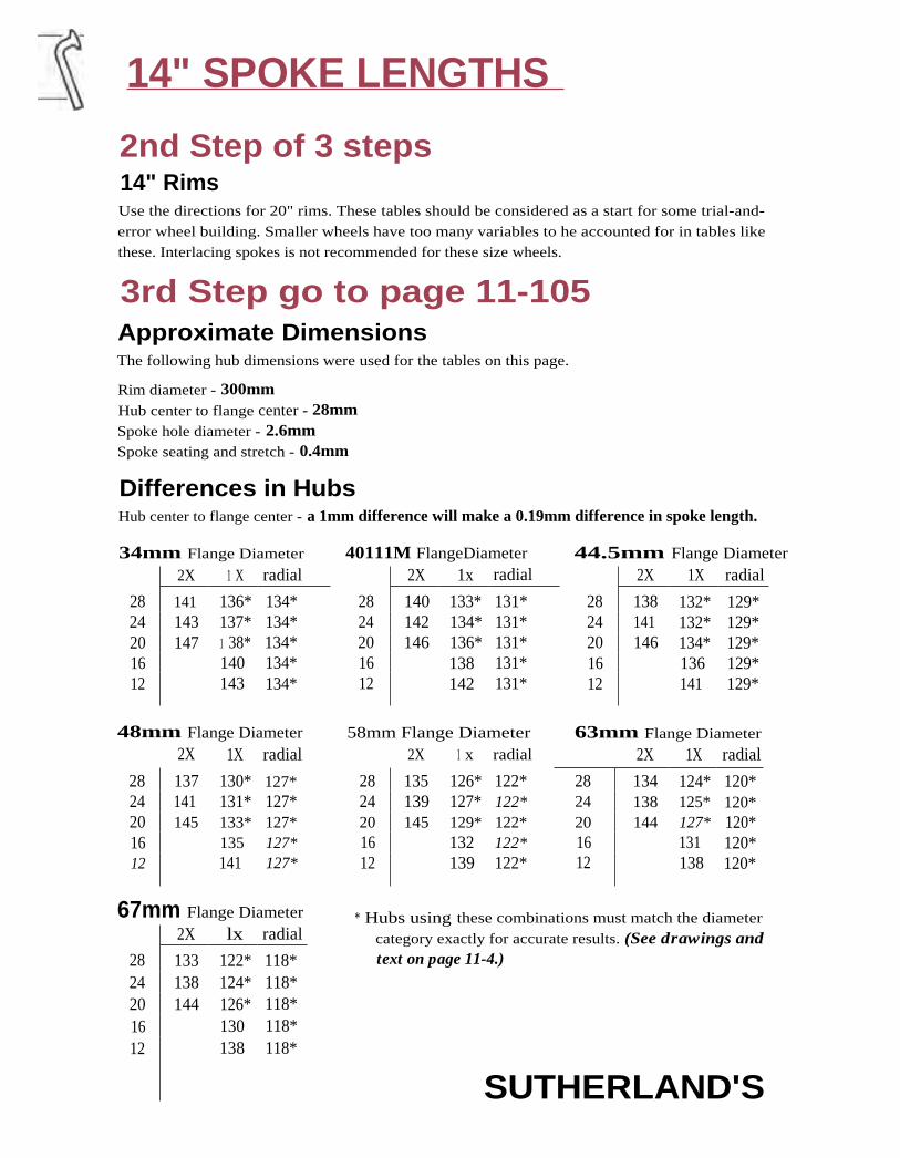
14" SPOKE LENGTHS
2nd Step of 3 steps14" RimsUse the directions for 20" rims. These tables should be considered as a start for some trial-and-
error wheel building. Smaller wheels have too many variables to he accounted for in tables like
these. Interlacing spokes is not recommended for these size wheels.
3rd Step go to page 11-105Approximate DimensionsThe following hub dimensions were used for the tables on this page.
Rim diameter - 300mmHub center to flange center - 28mmSpoke hole diameter - 2.6mmSpoke seating and stretch - 0.4mm
Differences in HubsHub center to flange center - a 1mm difference will make a 0.19mm difference in spoke length.
34mm Flange Diameter 40111M FlangeDiameter 44.5mm Flange Diameter2X 1 X radial 2X 1x radial 2X 1X radial
28 141 136* 134* 28 140 133* 131* 28 138 132* 129*24 143 137* 134* 24 142 134* 131* 24 141 132* 129*20 147 1 38* 134* 20 146 136* 131* 20 146 134* 129*16 140 134* 16 138 131* 16 136 129*12 143 134* 12 142 131* 12 141 129*
48mm Flange Diameter 58mm Flange Diameter 63mm Flange Diameter
2X 1X radial 2X 1 x radial 2X 1X radial
28 137 130* 127* 28 135 126* 122* 28 134 124* 120*24 141 131* 127* 24 139 127* 122* 24 138 125* 120*20 145 133* 127* 20 145 129* 122* 20 144 127* 120*16 135 127* 16 132 122* 16 131 120*12 141 127* 12 139 122* 12 138 120*
67mm Flange Diameter2X lx radial
28 133 122* 118*24 138 124* 118*20 144 126* 118*16 130 118*12 138 118*
* Hubs using these combinations must match the diameter
category exactly for accurate results. (See drawings andtext on page 11-4.)
SUTHERLAND'S

Rim RimISO/ Correction SpokeDistinguishing Features Model Factor End Dia.
20-298 -5 290
1 8-298 Levanter L17 -6 288
20-298 -5 290
Rim RimISO/ Correction SpokeDistinguishing Features Model Factor End Dia.
20-253 with dimples 17 (5) -29 242
25-253 7A -28 244
25-253 with dimples -30 241
Rim RimISO/ Correction SpokeDistinguishing Features Model Factor End Dia.
19 Mistral M19All -4 242
19 Mistral M19A -4 242
Ukai steel 9
Rim CrossMake Material Section
Sturmey-Archer steel
Sun Metal alloy s
Ukai steel p21
14x 1.75"
Rim CrossMake Material Section
Araya steel )
14x 1.75"Rim Cross
Make Material Section
Sun Metal alloy
14" SPOKE LENGTHS
3rd Step of 3 steps14 x 13/8"
SUTHERLAND'S

12" SPOKE LENGTHS
2nd Step of 3 steps12" RimsUse the directions for 20" rims. These tables should be considered as a start for some trial-and-
error wheel building. Smaller wheels have too many variables to be accounted for in tables like
these. Interlacing spokes is not recommended for these size wheels.
Approximate Dimensionsthe tollowing hub dimensions were used for the tables on this page.
Rim diameter - 250mmHub center to flange center - 28mmSpoke hole diameter - 6mmSpoke seating and stretch - 0.4mm
Differences in HubsHub center to flange center - a 1mm difference will make a 0.22mm difference in spoke length.
34mm Flange Diameter 40mm Flange Diameter 44.5 mm Flange Diameter 48mm Flange Diameter
l x radial 1 x radial 1X radial 1 X radial
20 113* 110* 20 111* 107* 20 110* 1 05* 20 108* 1 03*
1 6 115* 110* 16 114* 1 07* 1 6 112* 1 05* 1 6 111* 1 03*
1 2 119 110* 1 2 118 1 07* 1 2 117 1 05* 1 2 117* 1 03
58mm Flange Diameter 63 mm Flange Diameter 67mm Flange Diameter * Hubs using these1 X radial 1 x radial 1X radial combinations must
match the diameter
category exactly foraccurate results. (Seedrawings and texton page 11-4.)
3rd Step of 3 steps121
/2 X 21/4"Rim Rim
Rim Cross ISO/ Correction SpokeMake Material Section Distinguishing Features Model Factor End Dia.
20 1 05* 98* 20 1 03* 96* 20 1 02* 94*
1 6 1 08* 98* 1 6 1 07* 96* 1 6 1 06* 94*
1 2 115 98* 1 2 114 96* 1 2 114 94*
Sun Metal alloy
24-203
-28 1 93
Style J -25 199
Style M -27 196
24-203
steel
SUTHERLAND'S

10 x 1.5" P"'
10" SPOKE LENGTHS
2nd Step of 3 steps10" RimsUse the directions for 20" rims. These tables should be considered as a start for some trial-and-
error wheel building. Smaller wheels have too many variables to he accounted for in tables like
these. Interlacing spokes is not recommended for these size wheels.
Approximate DimensionsThe following hub dimensions were used for the tables on this page.
Rim diameter - 200mm
Hub center to flange center - 28mmSpoke hole diameter - 2.6mm
Spoke seating and stretch - 0.4mm
Differences in HubsHuh center to flange center - a 1mm difference will make a 0.22mm difference in spoke length.
Radial PatternHubs must match the hub diameter category exactly. (See drawings and text on page 11-4.)
34mm Hub - 87* 58mm Hub - 75*
40mm Hub - 84* 63mm Hub - 73*
44.5mm Hub - 82* 67mm Hub - 71 *
48mm Hub - 80*
3rd Step of 3 steps10x PA"
Rim T RimRim Cross ISO/ Correction Spoke
Make Material Section Distinguishing Features Model Factor End Dia.
Marzorati alloy t 25-194 Mini Westwood -9 182
Rim RimRim Cross ISO/ Correction Spoke
Make Material Section Distinguishing Features Model Factor End Dia.
Araya steel C HB 168 x 20 with dimples 17 (5) -30 141
SUTHERLAND'S

SPOKE LENGTHS
CALCULATING RIM CORRECTION FACTORSTo be sure rim is round, measure in several places.
This dimension will be called A.
1. Measure from next to one hole to next to the exact opposite hole.
2. Measure in units of millimeters, including tenths.
3. Avoid measuring within two holes of the rim seam.
4. Measure at four points equally spaced about the rim and get an average whichshould be rounded to the nearest 0.1 mm.
Measure the spoke nipple from the bottom
of the slot to the end.
This dimension will be called B.
1. Measure in millimeters, including tenths.
C Place a spoke nipple in the rim and measure
that part that extends beyond the rim.
This dimension will be called C.
1. Measure from the same points on the rim that "A" was
measured from (i.e., if "A" was measured from beside a raised
eyelet, "C" should be measured from beside a raised eyelet).
The theoretical rim radius the charts are based on will be called D.
D = 315 for 27" rims*300 for 26" rims
270 for 24" rims225 for 20" rims
200 for 18" rims
175 for 16" rims150 for 14" ri ms125 for 12" rims100 for 1 0" ri ms* also 700C, Sew-ups, and 28" rims.
The formula to find the correction factor from a rim not listed on the chart is:
(A+2 (B-C))- D = Correction Factor or (.5 x A) + B - C - D = Correction Factor.
2
SUTHERLAND'S

Figure A - 32 spokes Figure B - 40 spokes
SPOKE LENGTHS
NUMBER OF SPOKES
I D 32, 36 and 40 Spoke Wheels32 and 40 spoke wheels have similar spoke patterns as illustrated in figures A and B. With prac-
tice they can be easily told apart by looking at the distance between spokes at the rim.
36 spoke wheels have pattern illustrated in figure C.
20, 24 and 28 Spoke Wheels24 spoke wheels have a pattern similar to 32 and 40 spoke wheels.
20 and 28 spoke wheels have a pattern similar to 36 spoke wheels.
Figure C - 36 spokes
SUTHERLAND'S

Q SPOKE LENGTHS
SUTHERLAND'S

RimSpoke
End Dia.
392
397
391
18 x 13/8"Rim
SpokeEnd Dia.
380
RimRim Cross ISO/ Correction
Make Material Section Distinguishing Features Model Factor
Sun Metal alloy 14-400 M14A -10
24" & BELOW SPOKE LENGTHS 24 x 1.50", 24 x 1.75", 24 x 2.125"
Make
Rigida
RimRim Cross ISO/ CorrectionMaterial Section Distinguishing Features Model Factor
alloy ILL_A 20-507 A526F -21
RimSpoke
End Dia.
498
20 x 1.50", 20 x 1.75", 20 x 2.125"
Make
Rigida
RimRim Cross ISO/ CorrectionMaterial Section Distinguishing Features Model Factor
alloy 20-406 AS26F -27
Araya steel C ) 25-406 with dimples 17(4) -29
20" Sew-upsRim
Rim Cross ISO/ CorrectionMake Material Section Distinguishing Features Model Factor
Saavedra alloy 1 9 with rim washer Turbo -21
16" Sew-upsRim
Rim Cross ISO/ CorrectionMake Material Section Distinguishing Features Model Factor
Sun Metal alloy )19 M19A -26
RimSpoke
End Dia.
40911
RimSpoke
End Dia.
298
SUTHERLAND'S

24" AND BELOW SPOKE LENGTHS
SUTHERLAND'S

CONTENTS
12
TIRES
Tire and Rim DimensionsTire and rim types ....................... 2
Tire and rim fitType ......................................... 2
Width ....................................... 2
Diameter ................................. 2
Tire and rim markings/SO .......................................... 3
British ................................... 3-4Schwinn and Canadian ......... 4
Vredestein-Paragon(Netherlands) ......................... 4
French ..................................... 4
European ................................. 4
Measuring tires and rims ........... 5
Tire and rim width ...................... 6Classic rim cross sections
Hooked-bead orhooked-edge rims ................... 7Wired-on rims ......................... 7Schwinn rims .......................... 7
HB 575 x 25
Tire and Rim Charts Tubulars - Sew-upsCommon tire markings .... 8-15
LSO size designations ....... 8- 1 5
Bead seat circumference .. 8-15
Brake radius ....................... 8-1 5
Rim outside diameter........ 8-1 5
Tire outside radius ............ 8-15
Rim sizes ......................................... 1 6
Tire sizes ......................................... 16
Valve hole sizes ............................ 1 6
SUTHERLAND'S

TIRES
Tire widthTIRE AND RIM TYPESThe most common types of tires are wired-on, hooked-bead', and sew-up. Bothwired-on and hooked-bead tires have a wire embedded in the rubber at the inside
edge of the tire. Wired-on rims have straight sides. The bead seat of a wired-on tire iswhere the edge of the tire meets the rim. Air pressure in the tube keeps the bead ofthe tire pressed outward. Without air pressure, the bead can slip into the well in the
center of the rim allowing it to come off over the edge on another part of the rim.
Hooked-bead tires have a protruding bead that fits around the hooked edge of theri mm to
12
hold
-7) . the tire in place. (These rim cross sections are illustrated on
page
su▪ Sew-up tires, also known as tubulars or sprints, have the inner tube sewn in. Sew-*,a.i up rims lack flanges; the tire is held to the dished face of the rim by air pressure
and a special adhesive.
tA TIRE AND RIM FITles
0.1 Type: In the past, each rim type fit only the corresponding tire type. Now the dis-co tinctions are blurring. Many higher-pressure rims come with a ridge on the inside
edge of the rim flange which is similar to though smaller than the hooked edge of
a hooked-edge rim. Many folding tires must be mounted on rims with these
bumps to prevent stretching of the flexible, plastic bead material.
Width: Tires with an f502 Section Width 3 of between 1.45 and 2.00 times the
rim width (measured in millimeters between the inside of the flanges) should fitwell. Hooked-edge rims hold tires with a section width of up to 2.25 times the rim
width. Never use an inner tube that is too narrow for the tire in which it isinstalled: it may work at first but it will soon split at the seams.
Diameter: Bead and bead seat diameter are much more important dimensions than outsidediameter because they determine tire/rim fit. (Unfortunately, most tires are still marked with thenominal outside diameter. Since tires with equal outside diameters may differ slightl y in beaddiameter, they may not fit the same rim.) To ensure proper fit, tire bead diameter must be veryclose to rim bead seat diameter—in general, within I mm. If the tire is too large, it will blow offthe rim when inflated; if too small, the beads will pull down below the bead seat—if the tire canbe mounted at all.
1 True clincher tires, tires held on by a pronounced bead and a lubber flap under the innertube, are now obsolete in most parts of the world. Many people still use the term clincher to
refer to the wired-on and hooked-bead tires that have replaced them.
2 The former European Tire and Rim Technical Organization (ETRTO) markings have been
adopted by the ISO.
3 ISO Section Width is approximately equal to the distance between the beads, measured overthe tread in millimeters, divided by 2.5. (See Measuring Tires and Rims, page 12-5.)
SUTHERLAND'S

• 13 - 622•ISO rim widthbetweenflanges in mm
— bead seatdiameter in mm
TIRES
TIRE AND RIM MARKINGS
ISO Tire MarkingsThe ISO tire size designations are the only accepted international standard. Many tires carry
them in addition to the more familiar markings. For wired-on tires, the ISO tire markings consist
of two numbers as follows:
ISO tire section--P. 37 - 622.. bead diameter
width in mm in mm
I looked-bead tires may or may not use the HB designation, (see ISO rim markings below).
ISO Rim MarkingsFor wired-on rims, the ISO rim designations also consist of two numbers:
For hooked-bead rims, the ISO has designated HB numbers, although the above markings forwired-on rims are also seen. HB numbers are as follows:
HB 575 x 25
HB* for Hooked-Bead --- inside width in mmoutside diameter
of rim in mm
* HB cumbers are only found on hooked-bead rims.
BritishTires are marked in inches with two or three numbers as follows:
Nominal outsidediameter
28 x x 1 3/8
1standard width
(ISO 37-622)---------------- actual width
Tires designed for standard rim sizes carry only two numbers:
,_28 x 13/4 (I S O 44-571)
Nominal outside actual widthdiameter
28 x 1.75, (ISO 44-559)
Nominal outside actual widthdiameter
SUTHERLAND'S

codenominal width
(sometimes omitted)Nominal outsidediameter
TIRES
TIRE AND RIM MARKINGS (CONTD)
British (cont'd)Common fraction in width designation indicates wired-on type, decimal fraction indicateshooked-bead type.
Note that 26 x PA and 26 x 1.75 are different type tires and are not interchangeable.
SchwinnSchwinn tire markings are the same as the British markings described above with the followingexceptions (also noted in the tire size chart):
Schwinn British 150
26 x 1 1/2 26 x 1 1/4 32-59724 x 11/2 24 x 11/4 32-546
These two Schwinn sizes are not interchangeable with the British sizes which have identical markings.
Vredestein-Paragon (Netherlands)Markings are in inches, similar to those of the British system, except that when there arc threenumbers, the last two are reversed compared to the British markings. British and Vredestein-
Paragon tires in nominal sizes of 24" or less are not interchangeable.
28 x 1 3/8 x 1 5/8 (ISO 37-622)
Nominal outside - 1 – standard widthdiameter actual width
FrenchMarkings are in millimeters as follows:
07 0 x 35 C, (ISO 37-622)
In the French system, two tires have the same head seat diameter if the first numbers and the
final letters match.
Italian, German, Swedish, and the like.Many manufacturers mark their tires in inches although actual sizes are often different from trueBritish sizes. Look for an ISO designation or measure the tire as described, (see page 12-5).
SUTHERLAND'S
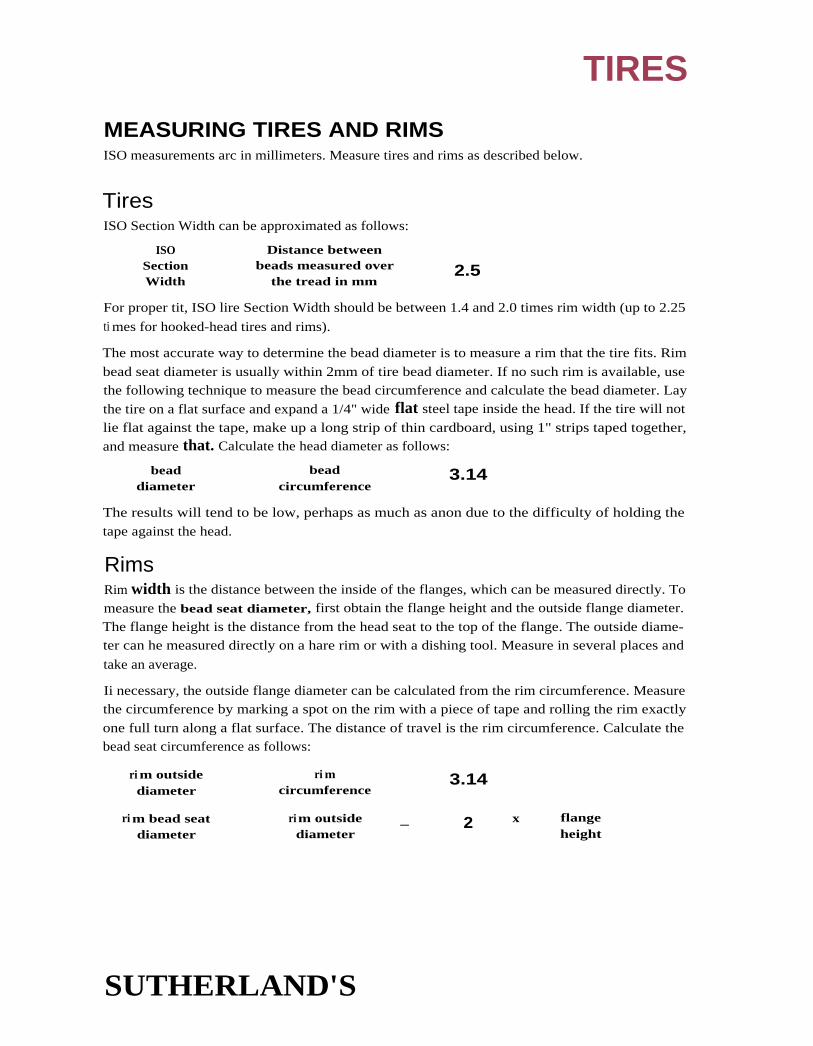
TIRES
MEASURING TIRES AND RIMSISO measurements arc in millimeters. Measure tires and rims as described below.
TiresISO Section Width can be approximated as follows:
ISO Distance betweenSection beads measured over 2.5Width the tread in mm
For proper tit, ISO lire Section Width should be between 1.4 and 2.0 times rim width (up to 2.25
ti mes for hooked-head tires and rims).
The most accurate way to determine the bead diameter is to measure a rim that the tire fits. Rim
bead seat diameter is usually within 2mm of tire bead diameter. If no such rim is available, use
the following technique to measure the bead circumference and calculate the bead diameter. Lay
the tire on a flat surface and expand a 1/4" wide flat steel tape inside the head. If the tire will not
lie flat against the tape, make up a long strip of thin cardboard, using 1" strips taped together,
and measure that. Calculate the head diameter as follows:
bead bead 3.14diameter circumference
The results will tend to be low, perhaps as much as anon due to the difficulty of holding the
tape against the head.
RimsRim width is the distance between the inside of the flanges, which can be measured directly. To
measure the bead seat diameter, first obtain the flange height and the outside flange diameter.
The flange height is the distance from the head seat to the top of the flange. The outside diame-
ter can he measured directly on a hare rim or with a dishing tool. Measure in several places and
take an average.
Ii necessary, the outside flange diameter can be calculated from the rim circumference. Measurethe circumference by marking a spot on the rim with a piece of tape and rolling the rim exactly
one full turn along a flat surface. The distance of travel is the rim circumference. Calculate thebead seat circumference as follows:
ri m outside ri m 3.14diameter circumference
ri m bead seat ri m outside — 2 x flangediameter diameter height
SUTHERLAND'S

TIRES
TIRE AND RIM WIDTHThe following rim widths are recommended for use with the tire sections to the left. Rim width
is measured between the flanges.
Rim Width Tire Section
(inside flanges) British ISO French
12 to 15mm 3/4 20 20
13 to 15mm 7/8 22 22
13 to 18mm 1 25 25
14 to 20mm 1 1/8 28 28
15 to 21mm 1 1/4 32 32
16 to 23mm 1 3/8 37 35
17 to 24mm 1 1/2 40 38
20 to 29mm 1 5/8 44 42
23 to 31mm 1 3/4 47 45
24 to 33mm 2 54 50
27 to 35.6mm 2 1/8 57 54
30.5 to 41 mm 2 1/4 62 57
SUTHERLAND'S

"Middleweight" 1.75 "Balloon" 2.125
.111- 35.8mm
Css 2s.7.2m224.6mm,7
30mmir.
14117.4
'19.8mm
"Lightweight" 1.375
Wired-on Rims
Narrow Westwood
E type
27.9mm
r%11 3m:1
Westrick***
R type
27.9mm
20.3mm
Endrick**
EA type
Westwood
F type
1.4111- -11111
.
38.1mm
711.124.6mm
ha/ 33mm— If-
20.3mm
35.4mm —
1.4_1,..124.6mm
35.8mm
27.2mm
TIRES
CLASSIC RIM CROSS SECTIONS*Hooked-bead or Hooked-edge Rims
E type Narrow Westwood
F type Standard Westwood EA type Endrick Pattern
K type Special Light-weight EB type Narrow junior Westwood R type Westrick Raleigh Pattern
Schwinn Rims
Schwinn 5-7 Schwinn S-2
"Lightweight" "Middleweight"
* Modern rims vary so much they defy neat classification.
** Schwinn S-6 is similar in shape to British Endrick.
***Schwinn S-5 is similar in shape to British Westrick.
SUTHERLAND'S

TIRE AND RIM CHARTSCommon Tire Markings (American, English, French, etc.): If width number is replaced by a dash a range of widths
is available in the same bead seat size.
ISO Size Designation: Tire Section measurements are in mm, followed by bead seat diameter in trim. For FIB numbers,
(see page 1 2-3). When a range of widths is available, it is shown with the standard width in bold face: 32-340 to 37-340.
Bead Seat Circumference: This is 3.14 times bead seat diameter.
Brake Radius: Subtract this value from the distance between brake bolt hole and axle center to obtain brake reach.
Rim Outside Diameter (assuming normal flange height): Actual value for a particular rim may be as much as 5mm
less, especially with narrower rims.
Tire Outside Radius: Use this value to calculate tire to fork clearance. Radius of standard width tires is in boldface.
n Indicates sizes that may not be interchangeable with other sizes with identical or similar markings. Use ISO markings to positively identify tire.Bead seat circumference = n x bead seat diameter
ISO Tire Vredestein*(V) Approx.* Approx.Bead Marking Swedish (5) Rim TireSeat (Width- North German (G) Outside Out-Dia - Bead Seat American Schwinn British Standard Brake Dia- sidemeter Diameter) Sizes Rim British Rim French Italian Unidentified (5U) Radius meter Radius
647 32-647 28x11/4 EA2 700 700x32 (V) 323 659 358
642 37-642 to 28x 1 % FS 700A 28x1 3/g 28x13/8(V), (S) 321 654 361 -44-642 EA4 28x1 ; x1'/8 700x35A 700x35A (V) 368
E4 ► 28x1 1/2 (S)28x11/2x1 3
/8 (S)
635 28-635 to 10. 28x11/2 ► 28x11/2 F10 700B 700B 28x—xl 1/2 (V) 317 649 348-40-635 to F25.0 n 28x11/2 700B (V) 36044-635 FA25.0 ► 28x1 1/2 (G)
► 28x1 5/8 (S)
631 32-631 ► 27x11/4 (5) 315 643 350
630 20-630 to ► 27x13/4 27x13/E K2 ► 27x11/4 ► 27x11/4 ► 27x1 r/4 (G) 315 642 338-
30-630 to ► 27x11/4 K25.0 27x11/4 34837-630 27x1V8 EA25.0
27x1
623 44623 ► 28 x 1 5/8 (S) 312 636 359

622 18-622 to47-622
700C► 28x11/2 -
28x13/428x11/4
F.13E7
700C28x 15/8x—
7000 28x—x1Y, (V)28x1% ► 28x—x1 5Ai (V)
311 634 334-361
(Canada) EA6 28x1 1/4 (G)28x13/4 (G)
► 28x1 5/8 (G)
622 44-622 28x1.75 28x1.75 (V), (G) 311 634 361
[609 40-609 27x Ph 304 622 34732x650
607 44607 27x11/2 303 619 346
599 32-599 to 26x1.375 300 611 331-
37-599 26x1.25 334
HB 611x20
597 32-597 to ► 26x13/4- S-6 26x1 '/4 E.A.1 650 26x11/4 (V) 298 609 333-37-597 (Schwinn) S-5 E.1 26x1 1/4 650).32 (V) 338
K.1EA23.5
590 28-590 to ► 26x13/8 ► 26x-13/8 E.A.3 650A 26x1% 26x1 '/ (V) 295 602 335-
38-590 to E.3 26x11/4 26x11/2x11/4 (V) 338
40-590 F.4 26x13/tix 26x13/8 A (G)
EA23.0 26x1'/2 (G)R23.0 650A (V)E23.0
587 36-WS 700Dx1.4 201 lel -ct cl 333
585 40-585 to ► 26x11/2 (S) 292 600 335-
47-585 26x 13/4 342Transit (5)
584 32-584 to ► 26x11/2 S-4 26x11/2 F9 650B ► 26x11/2 26x—x1 1/2 (V), (5) 292 599 327-
40-584 to 650B 26x1V8 26x15/8 6508 (V) 335-
50-584 26x1 3/8 (G) 342
26x1 3/8x1 1/2 (G), (S)26x1'/z x2 (SU)
571 20-571 26x1 S-7 ► 26x13/4 12 650C 26x13/4 26x13/4 (V) 286 585 333-
40-571 to ► 26x13/1 26x2x1 3/4 F.22.5 25x1 58 650x45C (V) 336
44-571 to 26x1 1/2 - 650x45C 26x2 (G)47-571 to (Canada)54-571
561 62-561 25x11/8 26x2.25 (5) 281 576 346
BSR on a Vredestein tire stands for British Standard Rim.

TIRE AND RIM CHARTSCommon Tire Markings (American, English, French, etc.): If width number is replaced by a dash (—), a range of widthsis available in the same bead seat size.
ISO Size Designation: Tire Section measurements are in mm, followed by bead seat diameter in mm. For fiB numbers.
(see page 12-3). When a range of widths is available, it is shown with the standard width in bold face: 32-340 to 37-340.
Bead Seat Circumference: This is 3.14 times bead seat diameter.
Brake Radius: Subtract this value from the distance between brake bolt hole and axle center to obtain brake reach.
Rim Outside Diameter (assuming normal flange height): Actual value for a particular rim may be as much as Sinm
less, especially with narrower rims.
Tire Outside Radius: Use this value to calculate tire to fork clearance. Radius of standard width tires is in boldface.
n Indicates sizes that may not be interchangeable with other sizes with identical or similar markings. Use ISO markings to positively identity tire.
Bead seat circumference = t x bead seat diameter
ISO Tire Vredestein*(V) Approx. Approx.Bead Marking Swedish (5) Rim TireSeat (Width- North German (G) Outside Out-Dia - Bead Seat American Schwinn British Standard Brake Dia- sidemeter Diameter) Sizes Rim British Rim French Italian Unidentified (SU) Radius meter Radius
559 40-559 to 26x1.4 26x1.75x2 26x2 26x2.00 (V) 279 573 321 -54-559 to 26x1.50 26x2.125 650x50 (V) 33057-559 26x1.6 650x50C 26x1.75 (G)
• 26x1.75 26x2.00 (G)26x1.9 26x2x1% (G)
HB 575x25 26x1.95 650x45 (G)26x2.026x2.125
HB560x20 24x1.375 560 316-24x1.25 313
547 32-547 to37 -547
24x11/4n 24x1 3/8
5-65- 5
24x11/4 24x1 1/2
beaded (G)273 559 308-
313(Schwinn)
541 28-541 to 600A 24x13/8 xl % (V) 271 554 305-37-541 ► 24x1V8xl% 310
1

540 32-540 to ► 24x11/8 ► 24x13/8 E.5 600A 24x13/s 24x1Ya xl 1/2 (V) 269 552 304-
37-540 ► 24x13/ F.3 600x35A 24x1 3/8 A (G) 309EA21.0 600x35A (V)F21.0 24x1 '/2 xl 3/s (5)R21.0 24 xl 3
/8 (5)24x 38C (SU)
534 40-534 ► 24x11/2 F8 6008 24x1 '/2 (V) 26 548 31024x1 '/2 600x38B (V)
531 40-531 ► 24x1 I/2 (S) 265 545 30824x1Y8x1 1/2 (5)
521 47-521 ► 24x13/4 5-7 24x13/4 532 310
520 25-520 to 24x1 520 286
47-520 1.• 24x1 Vs
► 24x13/4
508 32-508 22x 11/4 (V) 254 520 289550x32 (V)
507 40-507 to 24x1.5 5-2 600x45 24x1.75x2 24x2x1 3/4 (V) 253 523 295-
57-507 ► 24x1.75 24x1.75 304
HB 524x25 24x 1.924x2.024x2.125
503 50 503 24x2 251 518 304Transport (5)
501 32-501 to ► 22x1 3/a E.6 ► 22x11/4 250 514 283-
37-501 to F.2 550x32A 290
47-501 EA19.5
498 32-498 to ► 22x1 3/a (G) 249 510 284-
37- 498 22x1 3/8x1 1/4 (5) 289
490 32-490 to 5S0A 22x1 3/a A (SU) 245 502 280-
37- 490 ► 22 xl ,/axl 1/4 ► 22x1 1/4 (G) 285
489 32-489 to 22x11/2 ► 22x1 3/a (V) 244 501 279-
37- 489 550A 550A (V) 284
484 40- 484 to 550B ► 22x1 1/2 (G) 242 499 285-
44-484 22x1 5Axl 1/2 (S) 289
482 40- 482 ► 22x11/2 (V) 241 497 2845508 (V)
260
* BSR on a Vredestein tire stands for British Standard Rim.

TIRE AND RIM CHARTSCommon Tire Markings (American, English, French, etc.): It width number is replaced by a dash (—), a range of widths
is available in the same bead seat size.
ISO Size Designation: lire Section measurements are in nun, followed by bead seat diameter in mm. For HB numbers,
(see page 12-3). When a range of widths is available, it is shown with the standard width in bold face: 32-340 to 37-340.
Bead Seat Circumference: This is 3.14 times bead seat diameter.
Brake Radius: Subtract this value from the distance between brake bolt hole and axle center to obtain brake reach.
Rim Outside Diameter (assuming normal flange height): Actual value for a particular rim may he as much as St11111
less, especially with narrower rims.
Tire Outside Radius: Use this value to calculate tire to fork clearance. Radius of standard width tires is in boldface.
110. Indicates sizes that may not he interchangeable with other sizes with identical or similar markings. Use ISO markings to positively identify tire.
Bead seat circumference = it x bead seat diameter
ISO Tire Vredestein*(V) Appro)Bead Marking Swedish (5) RimSeat (Width- North German (G) OutsidDia- Bead Seat American Schwinn British Standard Brake Dia-meter Diameter) Sizes Rim British Rim French Italian Unidentified (5U) Radius meter
470 47-470 550C 22x13/4 235 482
1457 44-457 to 22x1.75 228 47354-457 22x2.125 IHB 473x7S
451 28-451 to 20111/2 5-5 n 20x11/4 E.51 20x1'/4 20 x 1 1/2 B5R (V) 225 46337-451 to 2011 1/4 5-6 EA18.0 500x35A47-451 • 200 Vs 818.0
EB18.0
HB 459x25 20x1.375 45820x1.25
440 28-440 to 500A 220 45237-440 to n 20x1 1/2 xl 1/440-440
438 37-438 n 20x11/4 n 20x11/2 (V) 219 450500x35A (V)
.* Approx.TireOut-sideRadius
266-1262
285
270-279
260-265
251-260-263
259

432 40-432 20x1'/2 (V) 216 446 259500x38B (V)
428 40 -428 to 20x1s/axl 1/2 20x2 (S) 214 442 257-
54-428 271
419 47-419 ► 20x13/4 S-7 20x 13/4 209 431 259
406 40-406 to 20x1.5 S-2 20x1.75x2 20x2x13/4(V) 203 422 244-
54-406 to ► 20x1.75 500x50 500x50 (V) 253
57-406 20 x1.9 500x45 20x1.75x2 (5)HB 422x25 20x2.125 20x2.00 (G)
400 37-400 to ► 18x13/s E.41 450x28 18x13/4 18x1'/2 BSR (V) 200 412 240-
54-400 18x1'/2 F.41 450x37 450x32A 20x2x1 3/4 ( S) 25718x13/4 FA 1 6.0 450x5520x2
390 37-390 to ► 450A 195 403 235 -
40-390 18x1 3/gx1 1/4 238
387 37-387 ► 18x13/8 18x1 3/8 (V) 193 400 233450x38A (V)
381 40-381 18x1 1/2 (V) 190 395 233450x38B (V)
369 32-369 ► 17x1lAt ► 1 6x11/2 (SU) 1 84 382 219
357 32-357 ► 17x11/4 (S) 179 371 214
355 44-355 to 18x1.75 450x45 18x2x13A(V) 177 371 219-
57-355 18x2.125 1 8x1.75 1 8x1.75 (G) 228
HB 371x25 18x2 (G)
349 32-349 to ► 16 x1 Vs ► 16x13/8 E. 3J ► 16x1'/4 174 362 209-
37-349 EA14.0 400x32A 214EB14.0
340 32-340 to ► 400A 170 353 205-
37-340 to ► 16x13/8x13/4 210-
44-340 217
339 37-339 ► 16x1Yii ► 16x1 3/a (V) 169 352 209400x35A (V)
337 37-337 ► 16x1 3/8 A (SU) 168 350 208
335 37-335 ► 16x1 3/8 (Polish) 167 347 207

TIRE AND RIM CHARTSCommon Tire Markings (American, English, French, etc.): if width number is replaced by a dash (-1, a range of widths
is available in the same bead seat size.
ISO Size Designation: Tire Section measurements are in mm, followed by bead seat diameter in mm. For HB numbers,
(see page 12-3). When a range of widths is available, it is shown with the standard width in bold face: 32-340 to 37-340.
Bead Seat Circumference: This is 3.14 times bead seat diameter.
Brake Radius: Subtract this value from the distance between brake bolt hole and axle center to obtain brake reach.
Rim Outside Diameter (assuming normal flange height): Actual value for a particular ri m may be as much as Smm
less, especially with narrower rims.
Tire Outside Radius: Use this value to calculate tire to fork clearance. Radius of standard width tires is in boldface.
110. Indicates sizes that may not be interchangeable with other sizes with identical or similar markings. Use ISO markings to positively identify tire.
Bead seat circumference = m x bead seat diameter
BeadSeatDia-meter
ISO TireMarking(Width-Bead SeatDiameter)
NorthAmericanSizes
SchwinnRim British
BritishRim French Italian
Vredestein*(V)Swedish (S)German (G)StandardUnidentified (SU)
BrakeRadius
Approx.*RimOutsideDia-meter
Approx.TireOut-sideRadius
330 40-330 16x 1 Vz (V) 165 344 208400x38B (V)
317 44-317 16x13/4 7 L_16x13/4 158 329 205
305 44-305 to 16x1.75 16x1.75 16x2x1 3/1 (V) 152 321 194-57-305 16x2.0 16x2 (V) 203
16x1.9 16x1.75x2 (S)
16x2.125
298 32-298 to ► 14xPla ► 14x1 3/8 21 14x11/4 14x1 1/2 BSR (V) 149 310 184-37-298 to (350A) F.2J 350x32A 1 4x13/8(S) 18947-298 EAU .7 14x15/8 196
288 32-288 to 14x2.125 350A 144 300 179-37-288 to 14x13/fix1YH ► 14x11/2x11/4 184-44-288 19157-288
286 37-286 ► 14x13/8 14x1 3/8 (V) 143 298 183350x35A (V)

120 —
110 —
100 —
90 —
80 —
70 —
60 —
50 —
40 —
30 —
20 —
8—
7.5 —
7
6.5 —
6 —
5.5
5-
4.5
4-
3.5 —
3-
2.5 —
2—
1.5 —
Rim Rim TireCircum- Brake Outside Outsideference Radius Diameter Radius
1955 311 634 3421835 292 596 3231635 261 533 2921475 235 482 2661314 210 431 241
1154 1 85 381 216
TIRES
TIRE INFLATION
PSI: Pounds per square inchATM: Atmospheres (Bar, Atti)
Kg/Cm2: Kilograms persquare centimeter
PSI ATM Kg/Cm2
9—130 —
98.5 —
TUBULARS SEW-UPS
Outside Diameters(See Spoke Length charts for various models - Chapter 11.)
700C Sew-ups700C sew-ups interchange with corresponding wired-on wheels without
adjustments to the brake shoe position.
8.5 — 26" Sew-upsPlease note there is a wide and potentially dangerous variation in what is referred
8 to as 26" sew-up rims. They vary between 579mm and 597mm in the outsidediameter. To be sure that the rim and the tire are designed to fit together, mea-
7.5 — sure the diameter cif the rim and confirm that the tire is designed for the rim'sdiameter. Note also, that 26" (650B) sew-up wheels with an outside diameter of
7— 597mm interchange with wheels with wired-on 6508 rims. These interchange
without having to adjust the brake shoe position.
6.5 —24" thru 18" Sew-ups
6 There are also wide and potentially dangerous variations in the 24" and
under category. Rims that have the same number vary in outside rim diame-
5.5—ter. Always confirm that you are installing only the tire designed to fit theri m's outside diameter.
Sew-up wheels in nominal sizes of 24" and under have much smaller tire and
rim diameters than wired-on wheels of the same inch sizes. Wired-on tires of
4.5 — the same inch size may not fit under the fork crown of a frame made for sew-
ups; to avoid a low bottom bracket and long brake reach, it is often best to use
4— the next larger sew-up size when substituting small sew-ups for wired-on tires.
TUBULAR TIRE SIZES3.5 — Matching
Tubular Wired-on
3— Size ISO size
28 (700C) 6222.5— 26 (650B)* 584
24* 521
2— 22* 470
20* 419
1.5 — 18 369
Moulton 17x1 '/4 has the same rim diameter as an 18" tubular tire rim.1 * Sizes vary between brands, (see Spoke Length Charts, Chapter 11).
10—0.5 — 0.5 —
VALVE HOLE SIZESPresta 6.8mm Dunlap 8.3mm Schrader 9.0mm
0 — 0 0 —
SUTHERLAND'S

CONTENTS
13
I NNOVATIVE,MAGURA,
SACHSHYDRAULIC
Cantilever BrakesShoe setup ................................... 2
Pad-rim position ........................ 2
Pad-rim clearance ...................... 2
Straddle hangers
Cable and pad setup ............. 2-3
Shimano link wires .................... 3
Anchored cable hangers .......... 4
Spring setup .................................... 4
Brake fit .................................... 4-5
Straddle cable end types ............. 5
How to use charts ....................... 6
Specification charts ................. 6-12
U-BrakesAbout .................................... 12
Reach comments ............... 12
Specification chart ............ 13
Roller-Corn BrakesAbout .................................... 14
Adjustments ....................... 14
Specification charts ........... 15-16
Side-Pull BrakesAbout .................................... 1 7
Adjustments ....................... 1 7
Specification charts ........... 1 7-25
Brake LeversAbout leverage ratios .... 28
Brake reach ....................... 29
Lever selection ................. 29
Dual cable levers ............. 29
Hydraulic BrakesSpecification chart .......... 30
Design elements
Innovative ...................... 31
Magura ............................ 31-38
Sachs ................................ 38
Brake Shoes and PadsNon-Standard .......................... 39
Center-Pull/Delta BrakesAbout ......................................... 26
Specification charts .............. 26-28
Brake Straddle CablesNon-Standard .......................... 40
SUTHERLAND'S

straddlehanger
straddle------ cable
cableanchor
caliper arm
pivot
BRAKES
CANTILEVER BRAKES
brake cable
Note:Careful mounting and servicing of
cantilever brakes is essential to pre-
vent the brake shoes from slipping
past the rim and into the spokes.
Shoe SetupPad-Rim Position: As the pads of a cantilever brake wear, they will contact the rim closer andcloser to the edge of the rim (away from lire). Adjust the pads close to the outside edge of the rim(close to tire). (See illustration below.) This is opposite to the way center-pull brakes wear.
Pad-Rim Clearance: Check for easy release of the straddle cable for quick wheel removal.
Side View
ri mpad
Brake Pads
Straddle HangersStraddle Cable and Pad Setup: The length of the straddle cable, the height of the strad-
dle hanger, and the brake pad-to-cantilever arm position all have an effect on braking power.Generally, the straddle cable bridge is set low and close to the tire for maximum braking force.The straddle cable should be high enough, however, to adequately clear the tire (and any
debris that may stick to the tire) or to fit over the front reflector hanger. In the event of brakecable failure, the front reflector hanger would prevent the straddle cable from catching in thetire and locking up the front wheel.
SUTHERLAND'S

Shoe-Caliper Arm Position
pivot right angle alignment
BRAKES
Straddle Hangers (cont'd)The straddle cable length (when adjustable) isset to transfer as much force to the brake pads aspossible. For the most efficient transfer of force,
the straddle cable and the line between the can-tilever pivot and the cable anchor should form a
right angle (90 degrees). (See illustration tothe right.) If the force is not at a right angle,part of the force gets wasted in pulling on the
brake post, which has no effect on braking.
Shimano Link Wires: For recent Shimanobrakes, there are a variety of straddle cablesetups available from Shimano.
The older Deore XT link wire has two tabs avail-able to engage the brake (marked F and RI and
was difficult to set up. When setting up a brakewith this link wire, ignore the F and R markings.
Older Shimano low profile brakes had cantilever link wires similar to the older Deore XT link
wire but with only one tab to hook onto the brake. These link wires use the Shimano Pro-Setgauge or Pro-Set jigs to properly set up the cable lengths, straddle angle, and the pad position.
When using the Pro-Set jigs, first choose the proper length jig and hook the jig on both the
brake cable and link wire. Pull the brake cable taut, and tighten the link carrier and brake anchorbolt. Set up the brake pads so that they are just touching the rims and are properly toed-in.
When the jig is removed, the brake should be properly set up.
Newer brakes use the unit link wires that have a pre-set length of cable housing in addition to
the normal link wire, (see figures below). With this setup of the straddle wire, there is no need
to tighten the straddle cable bridge, and the straddle cable length is equal on both sides. Byadjusting the length of the brake cable, the carrier unit height is set so the alignment mark linesup with the link wire. The pads arc then set up for proper clearance against the rim. Unit link
wires come in two types: alignment and dynamic. The dynamic type allows the link wire topivot in the link carrier; the alignment type is fixed.
Shimano Link Wires
Dynamic Alignment Pro-Set
SUTHERLAND'S

BRAKESStraddle Hangers (cont'd)Anchored Cable Hangers: For special cable hangers like the Cannondale Force 40+ and theSunTour Power Hanger (or Trek's version or Brodie's version), most of the above still applies: thecable hanger, anchor bolt, and pivot should be 90 degrees when the pads hit the rim though it ismore important to have the cable exiting tangentially from either side of the cable hanger whenthe brake contacts the rim.
Cannondaie Force 40+ SunTour Power Hanger
Spring SetupOn models equipped with adjustable springs, adjust the spring tension so that both pads contact
the rim at the same time. If this requires more than a little adjustment, check for other problems,(i.e. wheel not straight in drop-outs, incorrect dish, uneven pad wear, uneven pad installation,
asymmetrical braze-on stud location, spring ends sitting in different holes on multiple-hole
studs, etc.) Set spring tension as low as possible while also ensuring a good return. Some manu-
facturers recommend high spring tension on one side, especially for anchored cable hangers.
Factors that affect cantilever brake fit:1. Distance between brake pivots. Standard width is approxi mately 80mm.
2. For parallel brake boss orientation, use a Vernier caliper to verify brake bosses are parallel.
3. Rim diameter and drop-out to brake boss distance: The difference should be about 20mm.
4. Rim width.
5. Drop-out axle slot position relative to brake pivot.
S. Width of tire relative to width of rim (i.e. narrow rims with tat tires require a different setupso brake pads do not contact the tire. Sometimes this necessitates a lower profile shoe, longerstraddle cable length, etc.)
7. Position perpendicular to steering axis (straight forks may need to have canted pivot studs).
8. Spring-to-pivot stud compatibility (some brakes cannot achieve sufficient spring tension onolder, single-hole studs).
9. Pivot stud length and diameter: some mounting studs may be too long and the spring tensionbecomes too loose. Fix by filing the stud down. If the stud is too short, the brake will bind.
SUTHERLAND'S

Picture End Type Comments
Standard single head Sometimes can be used in
place of Dia Compe E.Z.R.•Dia Compe E.Z.R.
New Shimano Dynamicli nk wire
Double head adapter
Will work instead of
standard single head.
See page 13-3for set up instructions.
Provided with brake. Usedwith proper single head.
Older Shimano Deore XT
li nk wire
Can be replaced by single head
straddle wire and hanger.
Older Shimano low profileli nk wire
New Shimano alignment
type unit link wire
See page 13-3for set up instructions.
See page 13-3for set up instructions.
BRAKES
Factors that affect cantilever brake fit: (contd)
Usually, the problem is that the washer on the mounting bolt has been deformed (usually from
over tightening). Either replace the washer or flip it over. Over tightened bolts may deform themounting stud, causing it to flare out and bind. Either shape it down and use a longer mounting
bolt, or replace the brake with one which has a separate internal pivot sleeve.
Some bicycle manufacturers have run as much as .01" (.4mm) oversize on the outside diameter ofthe pivot stud. This may not pose a problem for inexpensive brake arms, as they typically have a
loose fit anyway. High-quality arms are likely to bind or not even mount. Consequentl y , it is
sometimes necessary to use a machinist's reamer to increase the inside diameter of the arm bush-
ing or try a different brake arm.
Note: On some pivot studs, the cylindrical part is only swaged in place. The studs are supplied to themanufacturer like this and need to be brazed-on to avoid possible subsequent failure (separation).
Check that the stud diameter isn't simply flared at the end due to over tightening of the mount-
ing bolt before assuming that it is oversized. If the stud diameter is flared, lightly file the flaredsection down to the original outside diameter.
Straddle Cable End Types
SUTHERLAND'S

BRAKES
CANTILEVER BRAKE SPECIFICATIONS
Post type Nut type Bolt type
Many nut-type and bolt-type brake pads use conical washers and mounting hardware to allow
adjustment for toe-in or rim sidewall angle.
How to use the cantilever brake specifications chart:Dimension A is the lowest position the brake pad can be bolted onto the cantilever arm. Note:often the pad can be rotated so that it can contact the rim even lower, but there may not be suf-
ficient play to get the brake pad to hit the rim squarely.
Dimension B is the highest the brake can go on the cantilever. The note for Dimension A also
applies here.
Center of Reach is the average of Dimensions A and B.
Shoe Type is usually either post-, bolt-, or nut-type. Post-type allows the pad to be mounted far-t her inboard. The nut- and bolt-types might be able to be mounted farther inboard with washersdepending on how many threads are available.
Adjustability indicates what can be adjusted on the brake shoe. T. Toe Adjustments - this is not
necessarily the case for post-type shoes, but some bolt- or nut-type shoes have built-in toe adjust-ments. FL, Reach Adjustments; the pads can be mounted farther from the brake arm.
Spring Tension Adjustment indicates what type of screws, nuts, or bolts to adjust in order toregulate the spring tension on the brakes. Gross spring tension adjustments sometimes may bemade by using different spring holes in either the cantilever body or the brake mounting boss ifthere are multiple holes. Usually, if both sides of the brake are adjustable, no spring hole is need-ed in the brake mounting boss.
Straddle Cable Ends indicates what style straddle cable is needed for the brake. In most cases, ifa single-head straddle wire is indicated, use the Dia Compe E.Z.R. straddle cable in place of thestandard single head straddle cable. Many brakes that need a double-headed straddle cable use a
standard single- or round-head straddle cable and conic with a bolted-on adapter that fits on theother end of the cable.
CenterAdjust-ability Spring Straddle
Make Part of Reach Shoe Toe-In (T) Tension CableEa Model Number (in mm) A Type Reach (R) Adjustment Ends
CAMPAGNOLO
Compact (all models) 26 20 32 nut T 2.5mm screws single
Standard (all models) 24 21 27 post T 3mm screws single
CANNONDALE
Coda A350 25.5 21.5 29.5 post T 13mm flats single
SUTHERLAND'S

BRAKES
CANTILEVER BRAKE SPECIFICATIONS (CONT'D)
Make& Model
PartNumber
Centerof Reach(in mm) A
ShoeType
Adjust-abilityToe-In (T)Reach (R)
SpringTensionAdjustment
StraddleCableEnds
CHANG STAR
(also marked Star
and Pro Star)
(plastic) 26 21 31 nut none single
880A 24 21 27 post T none double
882A 27 26 28 post T none single
885AC 29 24 34 nut none single
CRYSTAL DESIGNS
Power Brakes 21.5 13.5 29.5 post 13mm flats single
CURVE CYCLING
COMPONENTS 25 20 30 post 13mm flats doublet
DEAN
Rhino 25 20 30 post 13mm flats doublet
D1A COMPE
(also marked Gran-Compe)
Colbar 984 25 20 30 nut T 13 or 19mm flats single
FS-E CT-FE00 25 20.5 29.5 post T,R
New Gran-Compe NGC982 24.5 23 26 post T,R none single
X-1 CT-X100 25.5 21 30 n ut T 1 5mm flats single
X-1 CT-X101 25 20.5 29.5 post T, R 15mm flats single
X-1 Chroma CT-CROO 25.5 21 30 nut 1 5mm flats single
X-1 Chroma CT-CR01 25 20.5 29.5 post T, R 1 5mm flats single
XCE CT-XE01 25 20.5 29.5 post T, R 15mm flats single
XCE (alloy) CT-XE00 25.5 21 30 nut 15mm flats single
XCE (plastic) 26.5 21 32 nut none single
XCM CT-XM01 25 20.5 29.5 post T, R single
XCM (alloy) CT-XMOO 25.5 21 30 nut T 15mm flats single
XCM (plastic) 26.5 21 32 nut T none single
XCT CT-XT00 25 20 30 nut T single
XCT CT-XT01 25 20.5 29.5 post T,R none single
XCT (plastic) CT-XT100 25.5 21 30 nut 15mm flats single
XCU CT-XUOO 25 20.5 29.5 post T,R none single
960 23 post T,R none double
981 24.5 22 27 post T,R none single
983 24.5 23 26 post T,R none single
986 25.5 21 30 post T, R 13mm flats single
973 24.5 21 28 post T, R 13mm flats single
987 25.5 21 30 post T, R 13mm flats single
SUTHERLAND'S

•rBRAKES
CANTILEVER BRAKE SPECIFICATIONS (CONT'D)
Make Part& Model Number
Centerof Reach(in mm) A B
ShoeType
Adjust-ability SpringToe-In (T) TensionReach (R) Adjustment
StraddleCableEnds
GRAFTON
Speed Controllers
(earlier production) 23 20 26 post .050" screws doubler
Speed Controllers
(later production) 25.5 22 29 nut .050" screws doubler
GRAVITY RESEARCH
Rim Crushers 22 17 26.5 post T, R 11/16" flats doubler
Pipe Dreams 35 15 55 post T, R 11/16" flats doublet
I NTERLOCK
RACING DESIGNS
Switchback Type I 23 20 25 post T, R none none 2
Switchback Type II 23 20 25 post T, R 11/1C flats none2
LEECH!
706A 26 21 31 bolt T none single
700A 25.5 23 28 post T, R none double
(steel) 7065 25 20 30 nut alien single
MACHINE TECH
Zero Flex 23 16.5 30 nut 7 15mm flats double'
MAFAC
Criterium 25 25 25 post R none single 3
Tandem 25 25 25 post R none single 3
MARINOVATIVE
Cheap Trick 34.5 25 44 nut9 T,R11 16mm flats none12,13
Stoplite 25 20.5 30 bolt") T,R 1 1 16mm flats nonel3
PAUL COMPONENT
ENGINEERING
Stoplights 23 20.5 25.5 post T,R 16mm flats doubler
Stoplights MC 23 20.5 25.5 post T, R 16mm flats double'
Crosstops 23 20 25.5 post T,R 16mm flats single 13,14
POLYGON
— ("CANTISAFE") 27 24 30 post T, R 2.5mm screw single
— (steel) 25 20 30 nut T none single
RITCHEY
Logic, Logic W.C.S. 25 19.5 30.5 post T,R 2mm screw single
SUTHERLAND'S

SpringTensionAdjustment
StraddleCableEnds
none 5
none 5
none 5
%8 " flats 5
Vs" flats (16mm)55/8" flats (16mm)
flats 5
single
single
single
single
single
single
none
none
none
phillips screw
phillips screw
phillips screw
phillipsipps screw
phillips
screw
phillips screw
phillips screw
phillips screw
phillips screw
phillips screw
phillips screw
phillips screw
phillips screw
phillips screw
phillips screw
2mm screw
2mm screw
2mm screw
phillips screw
phillips screw
phillips screw
2mm screw
single
single
single
double6
double6
double 6
double 6
double6
double6
double 6
double6
double6
double 6
double 6
double6
double6
double6
double6
single
single
single
double6
double6
double6
double 6
BRAKES
CANTILEVER BRAKE SPECIFICATIONS (CONT'D)
MakeEa Model
PartNumber
Centerof Reach(in mm) A
ShoeType
Adjust-abilityToe-In (T)Reach (R)
SCOTT U.S.A.
Pederson SE-'89
(front) 4 24.5 21 28 post T,R
(rear) 4 24.5 21 28 post T,R
Pederson SE-'90
(front) 4 24.5 21 28 post T,R
(rear) 4 24.5 21 28 post T,R
Pederson SE-'91
(front) 4 24.5 21 28 post T,R
(rear) 4 24.5 21 28 post T,R
SHIMANO
1 00GS BR-M100 25.5 22 29 post T,R
200G5 BR-M201 25.5 22 29 post T,R
BR-M200 25.5 22 29 post T,R
400CX BR-C400 26.5 22 31 post T,R
700CX BR-C700 26.5 22 31 post T,R
Acera-X BR-M290 26.5 22 31 post T,R
Alivio BR-MC10 26.5 22 31 post T,R
BR-MC11 26.5 22 31 post T,R
BR-MC12 26.5 22 31 post T,R
BR-MC15 26.5 22 31 post T,R
Altus BR-ATI 0 26.5 22 31 post T,R
BR-AT11 26.5 22 31 post T,R
BR-AT20 26.5 22 31 post T,R
BR-AT21 26.5 22 31 post T,R
BR-CT10 26.5 22 31 post T,R
BR-CT20 26.5 22 31 post T,R
BR-CT50 26.5 22 31 post T,R
BR-CT90 26.5 22 31 post T,R
Deore BR-MT60 25.5 22 29 post T,R
Deore DX BR-MT62 25.5 22 29 post T,R
Deore LX BR-M550 24 1 9 29 bolt T
BR-M560 26.5 22 31 post T,R
BR-M561 26.5 22 31 post T,R
Deore LX BR-M565 26.5 22 31 post T,R
Deore XT BR-M730 25.5 22 29 post T,R
SUTHERLAND'S

•BRAKES
SpringTensionAdjustment
StraddleCableEnds
phillips screw
none
2mm screw
phillips screw
phillips screw
phillips screw
phillips screw
2mm screw
none
2mm screw
2mm screw
2mm screw
2mm screw
phillips screw
phillips screw
phillips screw
phillips screw
phillips screw
phillips screw
phillips screw
phillips screw
phillips screw
no centering
15mm flats
1 5mm flats
19mm flats
19mm flats
19mm flats
19mm flats
13815mm
1 6mm flats5
5
double6
single
double6
double6
double6
double6
double 6
single
single
single
single
single
single
double6
double6
double6
double6
double6
double6
double6
double6
single
single
single
single
single
single
single
single
single
single
single
single
single
CANTILEVER BRAKE SPECIFICATIONS (CONT'D)
MakeEr Model
PartNumber
Centerof Reach(in mm) A B
ShoeType
Adjust-abilityToe-In (T)Reach (R)
SHIMANO - (cont'd)
Deore XT (cont'd) BR-M 737 26.5 22 31 post T,R
BR-MC70 24.5 22 27 post T,R
Deore XT II BR-M732 25.5 22 29 post T,R
Exage ES BR-M520 26.5 22 31 post T,R
BR-M521 26.5 22 31 post T,R
Exage LT BR-M320 26.5 22 31 post T,R
BR-M321 26.5 22 31 post T,R
Exage 400 LX (plastic) BR-M351 24 1 9 29 bolt T
Exage Country (plastic) BR-M250 24 1 9 29 bolt T
Exage Mountain (alloy) BR-M454 24 19 29 bolt T
BR-M450 24 19 29 bolt T
Exage Trail (plastic) BR-M350 24 19 29 bolt T
BR-AT50 24.5 22 27 post T,R
STX BR-MC30 26.5 22 31 post T,R
BR-MC31 26.5 22 31 post T,R
BR-MC32 26.5 22 31 post T,R
STX Special Edition BR-MC30 26.5 22 31 post T,R
BR-MC31 26.5 22 31 post T,R
STX-RC BR-MC33 26.5 22 31 post T,R
Tourney BR-TY20 26.5 22 31 post T,R
BR-TY22 26.5 22 31 post T,R
XTR BR-M900 26.5 22 31 post T,R
SUNTOUR
(see also Dia-Compe)
Honor CT-HN00 25 22 28 post T,R
X-1 CT-X100 25 20 30 nut T,R
X-1 Chroma CT-CR00 25 20 30 nut T,R
XC 9000 CT-XC00 25 22 28 post T,R
XC Comp CT-XCO1 25 22 28 post T,R
XC Expert (Microdrive) CT-XX00 25 22 28 post T,R
XC LTD CT-XL00 25 22 28 post T,R
XC Pro CT-XPO0 25 22 28 post T,R
XC Pro CT-XPO1 25 22 28 post T,R
XC Pro (Microdrive) 25 22 28 post T,R
XC Pro SE/XC90004 CT-XP10 25 22 28 post T,R
XC Pro/XC Comp CT-XP20 25 22 28 post T,R
XC Pro/XC Comp 5E4 CT-XP I 1 25 22 28 post T,R
SUTHERLAND'S
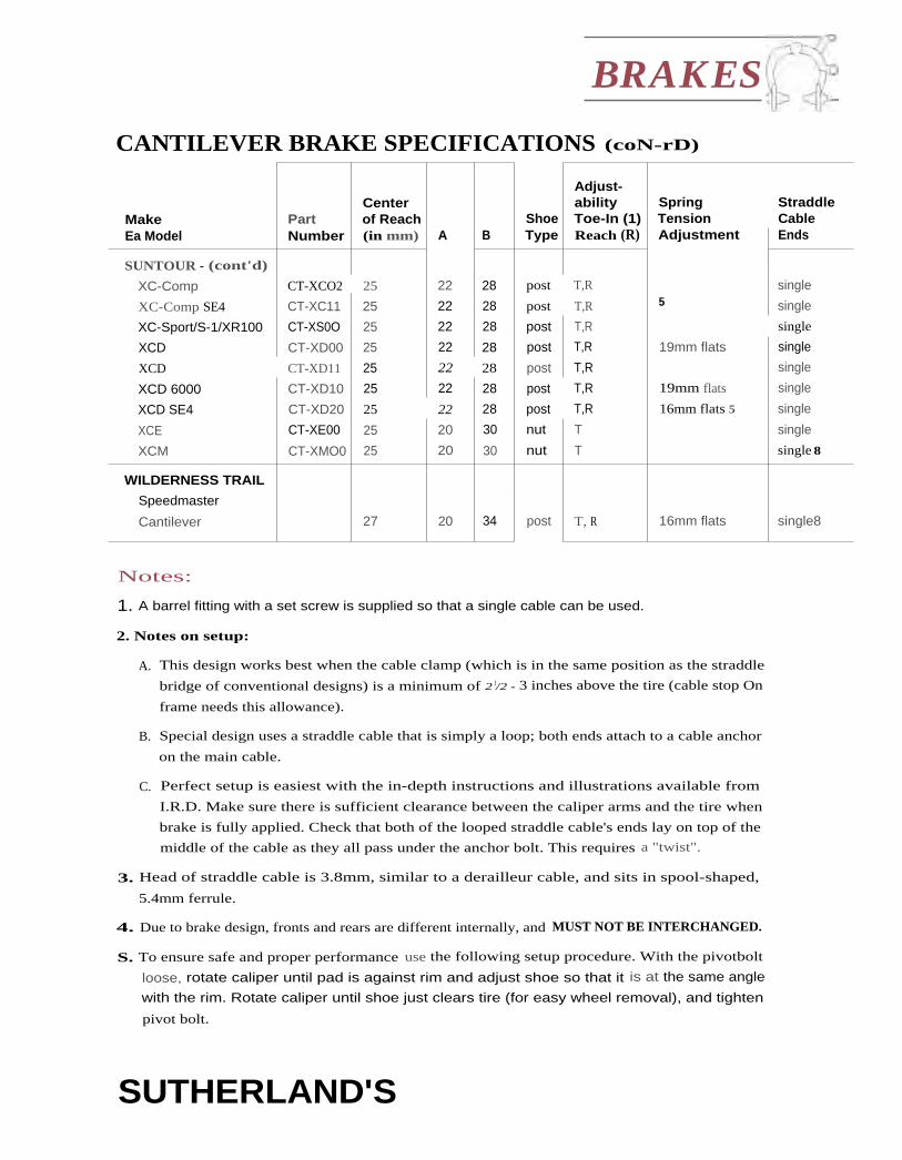
BRAKES
CANTILEVER BRAKE SPECIFICATIONS (coN-rD)
CenterAdjust-ability Spring Straddle
Make Part of Reach Shoe Toe-In (1) Tension CableEa Model Number (in mm) A B Type Reach (R) Adjustment Ends
SUNTOUR - (cont'd)
XC-Comp CT-XCO2 25 22 28 post T,R single
XC-Comp SE4 CT-XC11 25 22 28 post T,R 5 single
XC-Sport/S-1/XR100 CT-XS0O 25 22 28 post T,R single
XCD CT-XD00 25 22 28 post T,R 19mm flats single
XCD CT-XD11 25 22 28 post T,R single
XCD 6000 CT-XD10 25 22 28 post T,R 19mm flats single
XCD SE4 CT-XD20 25 22 28 post T,R 16mm flats 5 single
XCE CT-XE00 25 20 30 nut T single
XCM CT-XMO0 25 20 30 nut T single 8
WILDERNESS TRAIL
Speedmaster
Cantilever 27 20 34 post T, R 16mm flats single8
Notes:
1. A barrel fitting with a set screw is supplied so that a single cable can be used.
2. Notes on setup:
A. This design works best when the cable clamp (which is in the same position as the straddle
bridge of conventional designs) is a minimum of 2 1/2 - 3 inches above the tire (cable stop On
frame needs this allowance).
B. Special design uses a straddle cable that is simply a loop; both ends attach to a cable anchor
on the main cable.
C. Perfect setup is easiest with the in-depth instructions and illustrations available from
I.R.D. Make sure there is sufficient clearance between the caliper arms and the tire when
brake is fully applied. Check that both of the looped straddle cable's ends lay on top of the
middle of the cable as they all pass under the anchor bolt. This requires a "twist".
3. Head of straddle cable is 3.8mm, similar to a derailleur cable, and sits in spool-shaped,
5.4mm ferrule.
4. Due to brake design, fronts and rears are different internally, and MUST NOT BE INTERCHANGED.
S. To ensure safe and proper performance use the following setup procedure. With the pivotbolt
loose, rotate caliper until pad is against rim and adjust shoe so that it is at the same angle
with the rim. Rotate caliper until shoe just clears tire (for easy wheel removal), and tighten
pivot bolt.
SUTHERLAND'S

toBRAKES
CANTILEVER BRAKE SPECIFICATIONS (CONT'D)
Notes: (cont'd)6. Brake cable is connected directly to cable anchor on caliper. "Link cable" connects between
other caliper and moveable carrier that rides on brake cable, and actually has three heads
– the third serving as a finger grip to facilitate insertion and removal.
7. Comes with special alien head nut (works with standard nut-type pads).
8. l.ike a standard round brake cable head. Cables with thumb grip (either in line or on end) willnot work.
9. Allen nut or bolt. Side of conical washer may need to be filed down to fit.
10. Bolt only (long bolt provided). Conical washers with brake pads may be removed.
11. Reach adjusted with provided spacers.
12. Special cable set piece provided. Fits cables 1.8mm and smaller.
13. Low profile cantilever designed for use without a cable hanger.
14. Round head only.
U-BRAKE SPECIFICATIONSU-brakes follow many of the steps for pad and
cable setup of cantilever brakes except that, for U-brakes, the pads should be adjusted low on theri ms. As the brake pads wear, they creep up on theri ms. These brake shoes will take longer to hit the
tire sidewalk if adjusted farther down on the rim.
To get the best braking power from U-brakes,check the following three conditions. There
should he at least 20mm between the straddlehanger and the cable housing stop. Usually, the
straddle wire should be as short as possible. And,the straddle cable and the line between the brakeboss and the cable mounting point should form aright angle.
Reach comments: If conical washers are used,
measure the brakes with the conical washerssquared. To have a wider range of adjustments, tilt
the conical washer stack (sometimes at the sacri-fice of the brakes hitting the rim evenly).
SUTHERLAND'S

BRAKES
U-BRAKE SPECIFICATIONS (coNT'D)
MakeEa Model
ModelNumber
CenterofSlot A
Shoe*B Type
ShoeAdjust
SpringTensionAdjustment
StraddleCableEnds
CAMPAGNOLO
All Models 39 33 45 nut T1 3mm screws single
DIA COMPE
Advantage AD-990 38.5 35 42 post T 13&19mm flats 2 single's
XCE BA-XE00 40 33 47 nut T1 1 3mm flats 2 single
XCE-4050 BA-XE45 39.5 33 46 nut T1 single
INTERLOC
RACING DESIGNS
Progressive 37.5 35 40 post T,R 3/4" flats double
Rotary 37.5 35 40 post T,R 3 3/4" flats double
LEE CHI— (alloy) 737A 38.5 32 45 post none single
MCMAHON
Powerlink 38 34.5 41.5 post T,R 1 3mm flats none
SCOTT U.S.A.
Pedersen SE 40 34 46 post T,R none single
SHIMANO
Deore XT BR-M731 42.5 37 48 nut T1 2mm screws single
Deore XT II BR-M733 39 34 44 nut T1 2mm screws single
Exage Mountain
(plastic) BR-M451 41.5 35 48 nut T1 2mm screws single
SUNTOUR — (see DIA-COMPE)L_
Notes:* (See page 13-6 for shoe type drawings.)
1. Make adjustments with conical brake shoe washers. Use only shoes with conical washers.
2. Adjusting nuts are 19mm, and have an additional set of 13mm flats. Either wrench size can
be used. Newer models may have just 13mm flats.
3. Notes on setup:
A. The progressivity is affected by the total amount of pad extension. More extension
decreases peak pad pressure, less extension increases peak pad pressure; too little pad
extension will allow the rotor cam to lock up or pull through.
B. limit the total cable travel so that no matter how hard the brake lever is squeezed, the
rotor cam can't be pulled past the idler wheel.
4. Special round head with finger grip.
SUTHERLAND'S

BRAKES
ROLLER-CAM BRAKE SPECIFICATIONSThe rollers in a roller-cam brake move along aseries of ramps on the cam plate. The angle of the
ramps determines the amount of movement and Steep ramppressure at the brake pads. When viewed turnedon its side, the cam has a steep ramp that guides
the pads rapidly towards the rim. The next rampis shallower, producing greater leverage whilemoving the pad a smaller amount.
Adjust the brake so that when the pads contactthe rim, the rollers are just past the crest of thesteep ramp and are beginning to move along theshallow ramp.
Shallow ramp
Roller position of brake Roller position whenwhen it is released. pads contact the rim.
The roller hides the crest so it is difficult to see during setup. Mark the cam with a line perpen-
dicular to the shallow ramp, starting just past the crest. The line should point to the center of
the roller when the pads contact the rim. The rollers should not approach the reverse curve atthe end of the cam plate.
AdjustmentsFor minor adjustments, adjust the cable and/or the distance between the shoe and the caliper
arm. For larger adjustments, if the brake has two roller position holes, try the other position. If
the rollers aren't even close to the right position, try a different ram plate. Wilderness Trail Bikesand SunTour offer narrow and wide cam plates.
SUTHERLAND'S
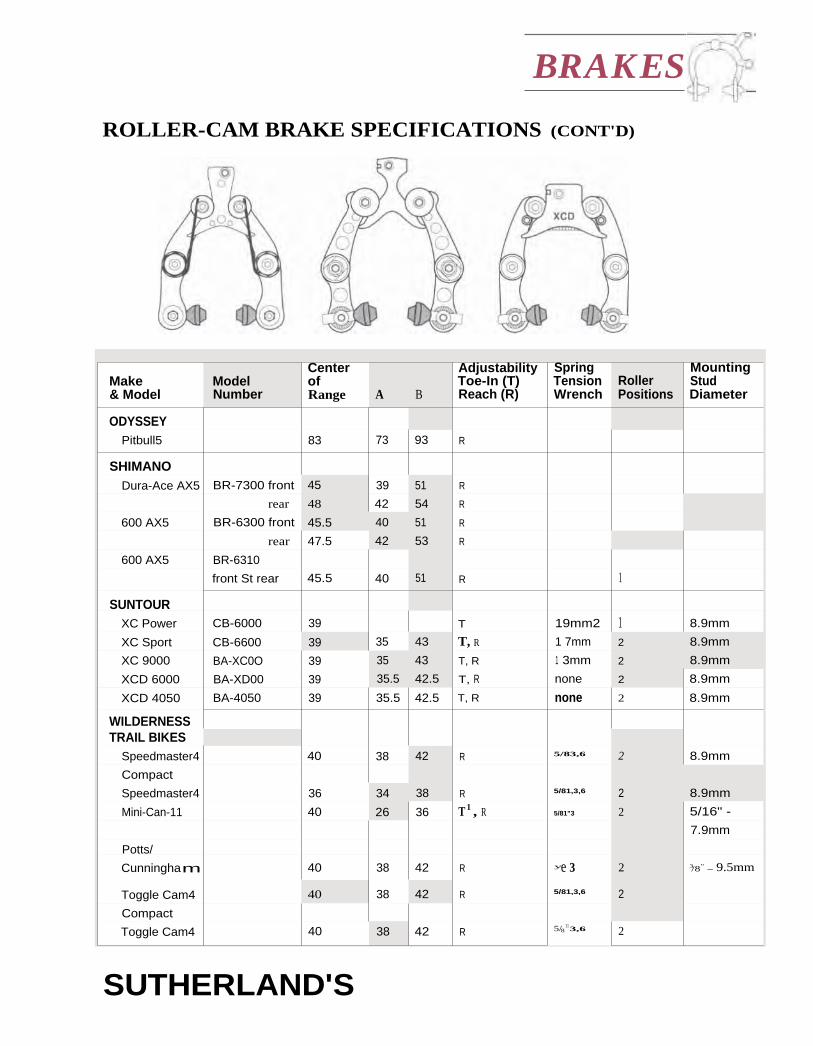
BRAKES
ROLLER-CAM BRAKE SPECIFICATIONS (CONT'D)
Make Model& Model Number
CenterofRange A B
AdjustabilityToe-In (T)Reach (R)
SpringTension RollerWrench Positions
MountingStudDiameter
ODYSSEYPitbull5 83 73 93 R
SHIMANODura-Ace AX5 BR-7300 front 45 39 51 R
rear 48 42 54 R
600 AX5 BR-6300 front 45.5 40 51 R
rear 47.5 42 53 R
600 AX5 BR-6310
front St rear 45.5 40 51 R 1
SUNTOURXC Power CB-6000 39 T 19mm2 1 8.9mm
XC Sport CB-6600 39 35 43 T, R 1 7mm 2 8.9mm
XC 9000 BA-XC0O 39 35 43 T, R 1 3mm 2 8.9mm
XCD 6000 BA-XD00 39 35.5 42.5 T, R none 2 8.9mm
XCD 4050 BA-4050 39 35.5 42.5 T, R none 2 8.9mm
WILDERNESSTRAIL BIKES
Speedmaster4 40 38 42 R 5/83,6 2 8.9mm
Compact
Speedmaster4 36 34 38 R 5/81,3,6 2 8.9mm
Mini-Can-11 40 26 36 T 1 , R 5/81"3 2 5/16" -
7.9mm
Potts/
Cunningham 40 38 42 R ye 3 2 3/8" - 9.5mm
Toggle Cam4 40 38 42 R 5/81,3,6 2
Compact
Toggle Cam4 40 38 42 R 5/8 11 3,6 2
SUTHERLAND'S

BRAKES
ROLLER-CAM BRAKE SPECIFICATIONS (CONTD)
Notes:1. Make adjustments with conical brake shoe washers. Only use shoes with conical washers.
2. Use SunTour 16/19mm wrench TA-210. For earlier versions, use a 15mm wrench.
3. A 16mm wrench will work also.
Spring Tension Adjustment:Screws 1 = Single alien screw in one caliper
Screws 2 = Allen set screw in each caliper
Flats 1 = Wrench-flats on one caliperFlats 2 = Wrench-flats on each caliper
4. Note: Different cam, linkages, rollers, and arms are available.
S. Mounts as standard side- or center-pull brake.
6. Toggle Cam and Speedmaster use the same arms (either compact or standard, depending on thewidth of the rims and how far apart the bosses are) and different cams and connecting
hardware.
7. Older Potts/Cunningham brakes are built for bosses slightly larger in diameter.
SUTHERLAND'S

BRAKES
SIDE-PULL BRAKE SPECIFICATIONSWhen selecting a brake, choose one so that the brake shoes are close to the center of the range of
motion t o and B) as shown in the illustration below. As the brakes wear or as the mountingadjusts, problems may arise if the brake is fitted at the highest or lowest limits.
The figures below are taken from manufacturers' catalogs.
A rough rule of thumb for the placement of the bolt hole for a side-pull brake is that the distance
from the bolt hole to the wheel's axle should be about half the bead seat diameter plus the cen-
ter of slot measurement. To mount side-pull brakes, use a mounting bolt and recessed nuts withalien heads for short reach brakes. Use normal nuts to fix onto the mounting bolt for normal
and long reach brakes.
AdjustmentsRecessed nuts usually take a 5mm alien wrenchand the fixing bolt is approximately 3cm for the
front and 2cm for the rear.
Toe adjustments are usually part of the brake padif that option is available, otherwise change the
brake pad or carefully bend the brake arm.
Centering adjustments arc most easily done by
pivoting the whole caliper around the mounting
bolt, though sonic brakes come with centering
adjustment screws.
Make Ez ModelModel CableNumber Side
Centerof Slot B
ACS
Boa R 82.5 70 95
860 R 77.5 70 85
CAMPAGNOLO
New Short Reach
Athena D500 L 46 40 51.5
Athena '93 BR-02AT L 46 41 52.5
Athena '94 BR-12AT L 46 41 51
Chorus C500 L 46 40 51.5
Chorus '92, '93 BR-02CH L 46 41 51
Chorus '94 BR-02CH L 44.5 39 50
Record '94 BR-04RE L 44.5 39 50
Stratos BR-02ST L 45 39 51
Veloce '93 '94 BR-02VL L 45 39 51
Xenon F500 L 46 40 51.5
SUTHERLAND'S

• BRAKES
SIDE-PULL BRAKE SPECIFICATIONS (coNTD)
Make & ModelModelNumber
CableSide
Centerof Slot B
CAMPAGNOLO (cont'd)
Old Short Reach
Gran Sport 117 47 42 52
Record (pre-'85) 2040/1 L 47 42 52
Super Record 4061/1 L 47 42 52
Triomphe 915/102 L 47 42 52
Victory 415/001 47 42 52
Normal Reach
Gran Sport 118 52 47 57
Record (pre-'85) 2040 L 52 47 57
Super Record 4061 L 52 47 57
Triomphe 915/101 52 47 57
CHANG STAR (also marked
Royal Star, C-Star, Star, or Cdr T)
Short Reach
Pro-Star 400 P400 44 39 49
N400 44 39 49
Normal Reach
( marked CEIT) CT500 50 43 57
Gran Star 500 GS 500-160 L 52 47 57
Pro-Star 500 P500 50 43 57
Long Reach
(marked CST) CT630 56.5 49 64
Pro-Star 500 P630AG R 56.5 48 65
N630 R 56.5 49 64
Pro-Star 400 N730A, N730S 62 53 71
BMX & Freestyle
1020A 82 73 91
1 080A R 93 81 105
810A, N810A,
N810S, 890MX
69.5 61 78
890A, N890A 77 68 86
FS980, FS981 R 77 67 87
MX1000A R 82.5 73 92
MX1010A L 82.5 73 92
MX900A R 75 66 84
MX910A L 75 66 84
P1020A 82 72 92
SUTHERLAND'S

BRAKES
SIDE-PULL BRAKE SPECIFICATIONS (CONT'D)
Make El ModelModelNumber
CableSide
Centerof Slot
CLB
Ultra Short Reach
Compact, Promo, L 42.5 38 47
Space Line
Normal Reach
Competition L 51.5 46 57
GL 47.60 L 53.5 47 60
Professional 3842 L 52.5 48 57
Long Reach
GL 48.65 L 56.5 48 65
GL 55.75 L 65 55 75
GL 63.85 L 74 63 85
DIA COMPS (also marked
Gran-Curve, Aero-Compe,
Royal-Compe)
Ultra Short Reach
Aero Gran-Compe AGC300/BL L 40 37 43
Aero-Compe AC300G L 40 37 43
BRS 500 8A50, BA50K L 41 38 44
Short Reach
a II all-400 L 45 39 51
a-5000 a-5000 400 L 45 39 51
Blaze BA-BE00-S L 46 40 52
BRS 200 BA20 L 46 40 52
BRS 200 BRS 200 L 45 39 51
BRS 300 BA35 L 44 39 49
BRS 400 BA45 L 44 39 49
BRS 400 BRS 400 L 44 39 49
BRS 500 BA55, BA55K L 45 42 48
BRS 500 BRS 500 L 45 42 48
BRS Blaze BA08 L 46 40 52
BRS Edge BA10 L 46 40 52
BRS Radius BA25 L 46 40 52
Edge BA-ED00-S L 46 40 52
New Gran-Compe NGC400 L 45 40 50
Ole 400 OLE400 L 45 39 51
Radius BA-RA00-S L 46 40 52
Radius BA-RA01-S L 45 39 51
Royal Compe II R01400 L 44 39 49
SUTHERLAND'S

SIDE-PULL BRAKE SPECIFICATIONS (CONITTD)
Make & ModelModel CableNumber Side
Centerof Slot B
DIA COMPE (cont'd)
Short Reach (cont'd)
Royal Gran-Compe RGC400 L 44 39 49400N, QS400N L 43 38 48
Normal Reach
500N 500N 50 43 57Aero-Compe AC500 L 53 48.5 57.5ct II cx11-500 L 51 45 57rx-5000 rx.-5000 500 L 51 45 57Blaze BA-3E00-N L 52 47 57BRS 300 BA37 L 52 47 57BRS 400 BM 7 L 52 47 57BRS 70 BRS 70 L 51 45 57BRS Blaze BA09 L 53 47 59DC Series 505, 506,
505Q 506Q
L 51 45 57
Gran-Compe
(marked DC 500)
GC500 L 52 47 57
New Gran-Compe NGC500 L 52 47 57
Ole 500 OLE500 L 51 45 57Royal Compe II RCII500 L 52 47 57Royal Gran Compe RGC500 L 52 47 57RI BA-RTO0-N 51 45 57VX BA-VX00-N 51 45 57VX BA07 L 51 45 57
500, QS500N,
500N, CX500N
R 50 43 57
Long Reach
730 730N R 62 53 71810 810N R 70 61 79Aero-Compe AC800 L 67.5 63 72
Big Dog (dual pivot) MX-999 L 69 58 80Bulldog MX-884 R 77 68 86FS-E BA-FE00 L 66 57 75FS-E 887E 887E L 66 57 75
XCM/XCT BA-XMOO 70 60 80
630 R 56.5 49 64
730 R 62 53 71
810 R 70 61 79
890 R 78 68 88
SUTHERLAND'S

BRAKES
SIDE-PULL BRAKE SPECIFICATIONS (CONT'D)
Make Ei ModelModel Cable CenterNumber Side of Slot
DIA COMPE (cont'd)
Long Reach (cont`d) 1 003 82.5 73 92
1020 82 73 91
1080 93 81 105
BMX & Freestyle
Big Dog (Dual Pivot) MXBIG I L 78.5 67 90
Bulldog FS884 77 68 86
FX FS880 77 68 86
FX (marked MX) FS880L 77 68 86
MX MX1000 82.5 73 92
MX MX883 77 68 86
MX MX884 77 68 86
MX MX900,
MX903
75 66 84
MX MX901 75 66 84
MX (marked Bulldog) MX884Q 77 68 86
Nippon FS883,
FS883L
77 68 86
Trial (marked MX) 903 75 66 84
Trial (marked MX) 1003 R 82.5 73 92
LEE CHI 600AG 52 47 57
896A 77 68 86
LC400AG 48 43 53
MAFAC LC-GL 52.5 45 60
LS-2, LC-L 50 44 56
MAVIC
Short Reach
Pro 420 L 45 42 48
Route 410 L 45 42 48
Super Pro 430, 440 L 45 42 48
451 L 45 42 48
Normal Reach
Route 410 L 50 46 54
MODOLO
Short Reach
Equipe L 46 40 52
Flash L 46 40 52
Master Pro L 46 40 52
SUTHERLAND'S

_1C, BRAKES
SIDE-PULL BRAKE SPECIFICATIONS (CONT'D)
Make 6x ModelModelNumber
CableSide
Centerof Slot A
MODOLO (cont'd)
Short Reach (cont'd)
Professional L 46 40 52
Q-Even L 45 40 50
Q-Exe L 45 40 50
Speedy 46 40 52
X-Eras L 45 40 50
X-Setra L 45 40 50
X-Tenos L 45 40 50
Normal Reach
Corsa L 50 43 57
Flash L 52 46 58
Professional L 52 46 58
Q-Exe L 50 43 57
Speedy L 50 43 57
Sporting L 50 43 57
Long Reach
Corsa L 57 49 65
Sporting L 56.5 49 64
T-EIT L 66 57 75
PEREGRINE
BMX FSX-111 75.5 66 85
SACHS
Short Reach
New Success BR-RNS00 L 45 40 50
7000 BR-R7000 L 45 40 50
5000 BR-R5000 L 45 40 50
Normal Reach
5000 BR-R5000 L 50 43 57
3000 BR-R3000 L 50 43 57
2000 BR-R2000 L 50 43 57
Elysee BR-RELY0 L 50 43 57
Long Reach
3000 BR-R3000 L 62.5 53 72
2000 BR-R2000 L 62.5 53 72
Elysee BR-RELYO 62.5 53 72
SUTHERLAND'S

BRAKES
SIDE-PULL BRAKE SPECIFICATIONS (CONT'D)
Make St ModelModelNumber
CableSide
Centerof Slot
SHIMANO
Short Reach
105 BR-1050-49 L 44 39 49
105 (Super SLR)1 BR-1055 L 44 39 49
600 BR-6200-49 R 44 39 49
600 Ultegra BR-6400-49 L 44 39 49
600 Ultegra (Super SLR)1 BR-6403-49 L 44 39 49
600EX BR-6207-49 L 44 39 49
600EX BR-6208-49 L 44 39 49
Dura-Ace BR-7200 L 44 39 49
Dura-Ace BR-7400 L 44 39 49
Dura-Ace BR-7402 L 44 39 49
Dura-Ace (Super SLR)1 BR-7403-49 L 44 39 49
Exage (Super SLR)1 BR-A500 L 44 39 49
Exage Action BR-A350-49 L 44 39 49
Exage Motion BR-A250-49 L 44 39 49
Exage Sport BR-A450-49 L 44 39 49
Light Action BR-L490 L 44 39 49
RX100 (Super SLR)1 BR-A550 L 44 39 49
Sante BR-5000 L 44 39 49
Normal Reach
1 05 BR-1050-57 L 52 47 57
105 BR-Z105 L 52 47 57
600 BR-6200-57 R 52 47 57
600 BR-6210 L 52 47 57
1 05 (Super SLR) BR-1055 L 52 47 57
600 EX BR-6207-57 L 52 47 57
600 EX BR-6208-57 L 52 47 57
600 Ultegra BR-6400-57 L 52 47 57
Dura-Ace BR-7210 L 52 47 57
Exage (Super SLR) BR-A500 L 52 47 57
Exage Action BR-A350-57 L 52 47 57
Exage Motion BR-A250-57 L 52 47 57
Exage Sport BR-A450-57 L 52 47 57
Light Action BR-L570 L 52 47 57
RX100 (Super SLR) BR-A550 L 52 47 57
BR-Z570 L 50 43 57
Long Reach
DX BR-MX10 R 79 70 88
Tourney BR-MX20 R 79 70
SUTHERLAND'S

BRAKES
SIDE-PULL BRAKE SPECIFICATIONS (CONT'D)
ModelMake & Model Number
CableSide
Centerof Slot
SHIMANO (cont'd)
Long Reach (cont'd)
Tourney BR-TS10 63 54 72
Tourney BR-TS10 R 70 61 79
Tourney BR-TS30 R 63 54 72
Tourney BR-TS40 R 63 54 72
Tourney BR-TS40 R 70 61 79
Tourney BR-TS40 R 79 70 88
Tourney BR-TS60 R 63 54 72
BR-Z640 L 56.5 49 64
BR-Z720 R 63 54 72
BR-Z790 70 61 79
SUNTOUR
(see also Dia Compe)
Short Reach
Cyclone 7000 CB-7100 44 39 49
GPX BA-GPOO L 44 39 49
SL BA-SL00 L 45 39 51
Sprint BA-SP00 L 44 39 49
Sprint 9000 BA-SP10 L 44 39 49
Superbe Pro BA-S1300 L 44 39 49
Superbe Pro BA-SB01 44 39 49
Normal Reach
Cyclone 7000 CB-8100 52 47 57
Superbe Pro BA-S1300-N 52 47 57
UNIVERSAL
Ultra Short Reach
Mod. CX 97 37 32 42
Short Reach
Mod. 68 1 02 47.5 41 54
Mod. 77 99/B L 45 40 50
Mod. 77 front 99/N 48 42 54
Normal Reach
Mod. 125 125 51 46 56
Mod. 51 front 100 L 50.5 45 56
Mod. CX 98 52.5 46 59
SUTHERLAND'S

BRAKES
SIDE-PULL BRAKE SPECIFICATIONS (CONT'D)
Make & ModelModelNumber
CableSide
Centerof Slot
WEINMANN
Short Reach
490 SQ 490 46.75 41 52.5
Carrera 400 400 46.75 41 52.5
Normal Reach
605 605 53 46 60
590 SQ 590 52 47 57
Alpha LT 570 570 50 43 57
Carrera 600 600 53 46 60
NDC 577 577 50 43 57
Long Reach
Alpha LT 720 720 62 53 71
Alpha TR 721 721 62 53 71
Alpha TR 801 801 70 61 79
Junior 1020 1020 83.5 74.5 92.5
Junior 730 730 62 53 71
Junior 810 810 70 61 79
Junior 890 890 78 69 87
NDC 727 727 62 53 71
NDC 728 728 62 53 71
NDC 808 808 70 61 79
PBS 300 714 714 66.5 62 71
PBS 300 804 804 75.5 71 80
SBS 200 7122 712 62 53 71
SBS 200 7922 792 70 61 79
Symetric 763 763 64 52 76
Symetric 923 923 83.5 75 92
Symetric 943 943 81 68 94
Notes:1 Super SLR models must only he used with t he matching levers that have stiffer return springs.
2 Hybrid of side- and center-pull designs.
SUTHERLAND'S

BRAKES
CENTER-PULL AND DELTA BRAKESPECIFICATIONSThese brakes should be mounted and centered the same as
side-pull brakes as shown in the illustration to the right.
Fitting a brake shoe at the highest or lowest limits may
cause problems as the pads wear or as the mounting bolt
is adjusted.
Note: Some Delta brakes have an additional reach adjust-
ment at the mounting bolt.
The figures below are taken from manufacturers' catalogs.
ModelMake Ex Model Number
Centerof Reach
CAMPAGNOLO
Delta
Croce D'Aune B500 44 39 49
Record ('90) A500D 47 38 56
CHANG STAR
610A 56 49 63
750A 69 60 78
CLB
Normal Reach
CLB 2 Front 53.5 48.5 58.5Racer Special 54 47 61
Long Reach
CLB 1/55.77 66 55 77CLB 1163.85 74 63 85CLB 1/48.65 56.5 48 65Half-Balloon Racer 81 71 91Racer 62 55 69Racer 73 60 51 69
DIA COMPE (Also marked
Gran-Compe, Royal-Compe)
-(current production) 610 54 47 61
-(earlier production) 610 56 49 63
Gran-Compe (marked
"Gran-Compe DC 510") GC510 50 43 57
Gran-Compe (marked
"Gran-Compe DC 700") GC700 61.5 52 71
SUTHERLAND'S

PMake Ea Model
ModelNumber
Centerof Reach
DIA COMPE (cont'd)
New Gran-Cornpe NGC450 48.5 42 55
750 69 60 78
MAFAC
Short Reach
Competition GL CnOA 44 39 49
Competition GL Cn1A 49 44 54
GT GT0A 43 38 48
GT GT1A 48 43 53
Normal Reach
2000 M0A 50.5 43 58
2000 MIA 55.5 48 63
Competition GL Cn2A 54 49 59
GT GT2A 53 48 58
Racer R0 50.5 43 58
Racer R1 55.5 48 63
S SO 51.5 44 59
Long Reach
2000 M 2A 60.5 53 68
2000 M3A 65 55 75
Competition GL Cn3A 58.5 51 66
Racer R2 60.5 53 68
Racer R3 65 55 75
Raid Raid 72.5 65 80
S S1 56.5 49 64
S S2 61.5 54 69
S S3 66 56 76
MODOLO
Delta
Kronos CP4 45 42 48
SHIMANO
Tourney BR-TC10, 30 54.5 47 62
Tourney BR-TO 0, 30 66 57 75
UNIVERSAL
Mod. 61 front N.105 54.5 49 60
Mod. 61 rear N.106 64 56 72
Sport front N.108 64 56 72
Sport rear N.109 -1 56
BRAKES
CENTER-PULL AND DELTA BRAKE SPECIFICATIONS (CONT'D)
SUTHERLAND'S
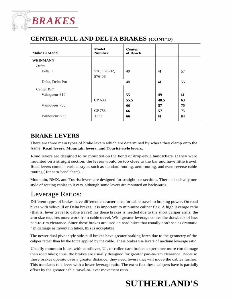
BRAKES
CENTER-PULL AND DELTA BRAKES (CONT'D)
Make Ei ModelModelNumber
Centerof Reach
WEINMANN
Delta
Delta II 576, 576-02,
576-0649 41 57
Delta, Delta Pro 48 41 55
Center Pull
Vainqueur 610 55 49 61CP 633 55.5 48.5 63
Vainqueur 750 66 57 75CP 753 66 57 75
Vainqueur 800 1232 66 61 84
BRAKE LEVERSThere are three main types of brake levers which are determined by where they clamp onto theframe: Road levers, Mountain levers, and Tourist-style levers.
Road levers are designed to be mounted on the bend of drop-style handlebars. If they weremounted on a straight section, the levers would be too close to the bar and have little travel.Road levers come in various styles such as standard routing, aero routing, and even reverse cablerouting ( for aero-handlebars).
Mountain, BMX, and Tourist levers are designed for straight bar sections. There is basically onestyle of routing cables to levers, although sonic levers are mounted on backwards.
Leverage Ratios:Different types of brakes have different characteristics for cable travel to braking power. On road
hikes with side-pull or Delta brakes, it is important to minimize caliper flex. A high leverage ratio
(that is, lever travel to cable travel) for these brakes is needed due to the short caliper arms; thearm size requires more work from cable travel. With greater leverage conies the drawback of less
pad-to-rim clearance. Since these brakes are used on road bikes that usually don't see as dramaticri m damage as mountain hikes, this is acceptable.
The newer dual pivot style side-pull brakes have greater braking force due to the geometry of thecaliper rather than by the force applied by the cable. These brakes use levers of medium leverage ratio.
Usually mountain bikes with cantilever, U-, or roller-cam brakes experience more rim damage
than road hikes; thus, the brakes are usually designed for greater pad-to-rim clearance. Becausethese brakes operate over a greater distance, they need levers that will move the cables farther.This translates to a lever with a lower leverage ratio. The extra flex these calipers have is partiallyoffset by the greater cable travel-to-lever movement ratio.
SUTHERLAND'S
BRAKES
BRAKE LEVERS (coN-rD)
Brake ReachDo not confuse short and normal reach brake levers with short, normal, and long reach brake
calipers. Short, normal, and long reach calipers refer to the distance from the mounting bolt to
the rim. Short and normal reach brake levers refer to the size hand the levers are designed for, or
rather, the distance from the lever to the handlebar.
Some drop-bar-style brake levers are designed for smaller hands and thus have less travel. This is
compensated for by reducing the leverage ratio so that the levers get the full amount of cable
travel. These levers will not be as powerful as standard reach levers which are for side-pull
brakes. This is partially offset since people with smaller hands weigh less and do not need as
powerful brakes for comparable stopping distances. The leverage ratio of drop-bar-style brake
levers for small hands is often close to the leverage ratio for dual pivot brakes.
There are various designs for both the brake lever and the brake caliper to get high initial travel
and still have good power without bottoming the lever against the bar. These brake systems are
designed for mountain bikes where greater pad-to-rim distance is desirable. There are also caliper
designs where though the rear brake has less power, the action of either brake lever feels the
same because the amount of total flex is the same for each side: for the rear, the flex is in the
longer cable run; for the front, the flex is in the longer caliper arms. Other lever designs have
reach adjustments for tuning the brakes' response to the rider.
These are generalizations that vary depending on the geometry of the individual caliper and the
cable and straddle wire setup. The action of roller-cam brakes really depends on the cam itself,
though low leverage and greater travel allow for greater play when adjusting the brake and cam.
Lever SelectionFor the most efficient brakes, use levers designed for the particular calipers you are using. Levers
designed for side-pull brakes do not offer enough travel for cantilevers and the pads do not ride
far enough away from the rim to allow using the quick release on the caliper. It is possible to use
levers designed for dual pivot brakes with cantilevers. There will be the same problems as above,
but to a lesser degree (whether this is acceptable or not depends on the rider).
Remember to check for proper lever travel, pad-to-rim clearance, and braking power. Does the
lever bottom-out against the handlebar? Does it feel like there is enough braking power? Too
much? Are the levers easy enough to reach? Will your hands cramp when using the brakes for
long periods of time?
Dual Cable Brake LeversSome brake levers are designed for a special double cable or for two cables. These are used on
tandems which have two caliper brakes and one huh brake. When using these levers, remember
that different types of brakes have different characteristics and it is usually best to use similar
brakes when they are attached to the same lever. Do not have a cantilever and hub brake con-
nected to the same lever.
SUTHERLAND'S

HS 66
center bolt
center bolt
center bolt
center bolt
483
481
484
482
HS 77
MATHAUSER
Pro
Touring
BMX
ATB
center bolt
center bolt
MAG URA
Hydro-Stop Mountain cantilever
HS 221 HS 22 Raceline
SACHS
Hydro Pull N/A
cantilever
center bolt
center bolt
SCOTT/ MATHAUSER
Superbrake
w/extender bushing
HS 22
HS 66
Make & ModelModel BrakeNumber Mounting
I NNOVATIVE BICYCLE
CONCEPTS
HydroCeps 940 940 cantilever
•BRAKES
HYDRAULIC BRAKE SPECIFICATIONSSpecification table does not include disc brakes.
Notes
CenterofSlot
Mounts on cantilever bosses,
brake pads mount directly on
hydraulic pistons.1
26 18.5 33
30 22.5 38
With Evolution adapter,
(otherwise see Magurasection page 13-32).
28 22 33.5
Brake pads mount directly
on hydraulic pistons.
(See "Center BoltInstallation" page 13-33.)Brake pads mount directly
on hydraulic pistons.
34 39 49
front brake must be mounted 52.0 39.0 65.0
BEHIND the fork, or DAMAGE 52.0 39.0 65.0
TO THE BRAKE AND INJURY 66.0 49.0 83.0
TO THE RIDER MAY RESULT! 52.0 39.0 65.0
Lever and cable replacement
used with current brakes.
scissors-like design.' 48.0 39.0 57.0
scissors-like design1 54.0 45.0 63.0
1 System is factory sealed; no user-service is intended, other than shoe replacement.
SUTHERLAND'S

Horizontal Distance FromCenter of Post to Rim (in mm)
19-39, 29-492
Centerof Slot
30
BA
22.5 38
BRAKES
HYDRAULIC BRAKE SPECIFICATIONS (CONTD)
Design Elements - Service Notes
Innovative Bicycle Concepts HydroCeps 940Ifie IBC HydroCeps 940 is a hydraulic cantilever brakeset for straight handlebars. It comes with
its own brake bridge, an essential part of the brake system. The brake bridge also acts as part ofthe quick release; it spreads the brake pads apart, making room for the wheel to be removed.
2 With adapters switched between left and right sides.
The hose fittings and brake pad screws are English threading. The hoses are a crimped, barbed
fitting and do not rotate easily. The hose fittings and bleed screws are threaded differently, so be
careful not to mix up the holes on the cylinders if replacing the hoses. Install the hoses as close
to the frame as possible: looping them close ensures that they will not snag on objects.
There is an adapter to fit the Shimano Rapidfire and Rapidfire Plus shifter models without the
optical gear display option. The adapter bolts onto the brake lever itself. The brake pads are bolt-
ed to plates on the slave cylinders. The brakes need little, if any, toe adjustment. If the brakes do
squeal, you can toe the pads by placing something wedge-shaped (like a flathead screwdriver)
under the leading edge of the brake pads and squeezing the lever to bend the brake pad and
backing plate away from the rim.
MaguraThe Magura hydraulic brakes are a modular system much like standard brakes are. The masterhydraulic cylinder (the hydraulic cylinder that you push on) is incorporated into the brake
lever. 1-here are two kinds of brake levers; one for straight handlebars (such as mountain bikes)
or ones for drop-style bars (like road bikes). There are two different kinds of slave cylinders (the
cylinders that push the pads to the rim); a single slave cylinder that is mounted as part of a side-
pull sty le brake and a dual slave cylinder arrangement where each cylinder is mounted on either
side of the rim. There are adapters to fit the slave cylinders to both popular brake style mount-
ings: cantilever bosses and side-pull centerholts. There are also special brackets that can be
brazed onto the frame or fork.
Brake Model Lever Style Slave Cylinder Style Normal Mounting
HS 22 Mountain Dual Cantilever3
'HS 22 Raceline Mountain Dual Cantilever3
HS 66 Road Dual U-bracket3
HS 77 Road Single Side-pull only
HS 77 Raceline Road Single Side-pull only
3 Use cantilever, U-bracket, or braze-on mounts. Make sure to use the right adapter or bracket.
SUTHERLAND'S

Horizontal distance4 fromcenter of post to rim (in mm)
Adapter SetAdapter Set w/Quick-ReleaseModel Number Model Number A
22.5-27.5 830201 830211 22.5 38
17.5-22.5 830202 830212 22.5 38
12.5-17.5 830203 830213 22.5 38
BRAKES
HYDRAULIC BRAKE SPECIFICATIONS (coNrc)
Magura (cont'd)HS 22 is a mountain-style brake lever with the dual slave cylinders and usually comes with thecantilever adapter. HS22 can be used with the 1J-bracket or braze-on brackets, also. Make sureyou have the right adapter or bracket.
HS 22 Raceline is similar to the HS 22 though it is slightly lighter. It uses the same hardware asthe I IS 22.
HS 66 is a road-style brake lever and has the same dual slave cylinders as the HS 22. Normally,[his lever is matched with a Ll-bracket centerbolt mounting, but this lever may also be used witha cantilever adapter for a tandem or touring bike.
HS 77 has the same master cylinder as the 115 66, but uses the single slave cylinder mounted to amore conventional looking side-pull style caliper.
Hydro-Stop brake is the predecessor to the IIS 22. The older cantilever adapter sets weredesigned for the Hydro-Stop.
Cantilever Adapter Installation (HS 22 or HS 66)Older models had different adapters for different rim-to-brake post distances. The new Evolutionadapter is a universal fit. Older adapter sets were used with the older Hydro-Stop brake.
Choose the appropriate adapter for standard cantilever mounts from the chart below.
Older Adapter Sets For Standard Cantilever Bosses
4 Includes 2mm distance on each side between rim and brake pads.
The flat-sided washer (labeled with the flat side up) should be placed on the brake post first. Thequick release for the Evolution adapter is used in conjunction with the normal Evolution adapter.
Clamp the slave cylinders into the adapters so that the pads are about 2-3mm from the rim and
the pads hit the rim flat (toe adjustment should not be necessary). The Evolution adapter has aslight ball joint for minor angle adjustments, but the larger angle adjustments should he done
by rotating the offset upper brace legs on the adapters – a 13mm open end wrench may beneeded for sufficient leverage. Likewise, adjust the distance from the pads to the rim as best aspossible at the adapter, then fine tune by turning the reach screw on the master cylinder.
SUTHERLAND'S

BRAKES
HYDRAULIC BRAKE SPECIFICATIONS (CONT'D)
Magura (cont'd)
Cantilever Adapter Installation (HS 22 or HS 66) (cont'd)Evolution Adapter Set For Standard Cantilever Bosses
Horizontal distance4 fromcenter of post to rim (in mm
Adapter SetModel Number
Adapter Setw/Quick-ReleaseModel Number A
0322168 22 33.5[19-39 0322166
4 Includes 2mm distance on each side between rim and brake pads.
Center Bolt Adapter Installation (HS 22 or HS 66)Magura recommends that Li-Brackets should be mounted behind the tront fork to simplify possi-ble installation of light brackets or reflectors.
U-Brackets For Centerbolt Mountings
I -
BracketHorizontal distance 4 fromcenter of post to rim (in mm) A
BracketB Part Number
A 19-27 59 66 0321368
B 19-27 62 69 0321373
C 19-27 65 73 0321354
D 19-27 71 80 0321381
E 28-36 83 92 0321386
4 Includes 2 mm distance on each side between rim and brake pads.
Bolts For Centerbolt Mountings (non-recessed nuts)
Bolt Bolt Number
Front 0321353
Rear 0321352
Rear, "Pletscher" type plate 0321351
As with the cantilever adapters, the slave cylinders clamp into the Li-bracket but there is noadjustability for toe-in. First, adjust the pad-to-rim distance at the bracket; then, fine tune andadjust for pad wear at the master cylinder.
Center Bolt Adapter Installation (HS 77)The HS 77 should come with the proper mounting kit: bolts for recessed nut mounting, part#0322018. Adjust the rim-to-pad distance by rotating knurled screw around the slave cylinder.Also, use the micro adjustment screw in brake lever.
SUTHERLAND'S

Horizontal bracket to rim distancedifference in mm
BracketB-A Part Number
6 03212569
BRAKES
HYDRAULIC BRAKE SPECIFICATIONS (CONT'D)
Magura (cont'd)
Braze-on Bracket Adapter Installation (HS 22 or HS 66)Special lightweight, dedicated braze-ons and their adapters are available for the HS 22 or HS 66slave cylinders, part #0321256. They adjust vertically 6111111 and pad-to-rim 9mm.
Braze-on Brackets
Brake ShoesDue to system design, it is unnecessary and undesirable to toe-in the pads. Pads should be par-
allel to the rim. Magura has two pads, each with rubber compounds for different applications:
Shoe Part # for HS 22 or Part # for HS 77Color Application HS 66 (snap-on) (bolt-style pad)
Black polished or anodized aluminum rims 0321406 0322035
Gray hard-anodized, ceramic, or composite rims 0321407 0322036
If the brake line is to be routed through braze-ons, (see instructions for shortening tubing
on page 13-36).
ServicingFor major service of Magura brakes, have the following spare parts on hand:
PartDescription Number
Hydraulic line tubing 610150Compression ferrule (have several of these on hand) 432264Compression collar (threaded) 432268Barbed fitting (threaded)* 432233Syringe (for adding fluid) w/rubber gasket and fill and bleed hoses 321236Spare rubber gasket (they have a limited life span) 431882Special nylon blocks for holding tubing while inserting barbed fittings 431883
* Old-style, silver brakes used smaller diameter (5mm vs. 6mm) with threaded barbed fitting.
SUTHERLAND'S

BRAKES
HYDRAULIC BRAKE SPECIFICATIONS (coNrcs)
Magura (contd)
The Barbed FittingInstalling a new barbed fitting:
1. Cut the tubing cleanly and perfectly square with a razor knife.
2. Clamp the end of the tubing securely in a vise with special nylon clamp blocks; leave 15 mm
(9116 1) of tubing above the blocks.
3. With a plastic hammer, gently tap a barbed fitting down into the tubing completely. Make sure
it remains straight and the line doesn't slip down further into the blocks.
4. t he barbs on the barbed fitting will provide enough of a seal to allow the fitting to rotate
without leaking.
The Compression CollarInstalling a new compression collar fitting:
1. Establish the correct tubing length. Be generous—it's easier to shorten than to lengthen!
Carefully measure and mark where to make the cut.
2. Cut the tubing cleanly and perfectly square with a razor knife.
3. If there is a tubing protector, slide it up the brake line and out of the way.
4. Slide the compression collar up the line and out of the way. Position a new compression fer-rule with the rounded end facing the end of the tubing. While maintaining light downwardpressure on the line to ensure that a good scat results, slide the collar back down and screw intightly. leave only 2-2.5mm of space between collar wrench-flats and slave cylinder body.
Shortening the hydraulic line tubing:
1. Completely unscrew the fitting on the hydraulic tubing where it connects to the slave cylinder
(caliper), and carefully pull up the end of the tubing.
2. Establish the correct tubing length. Be generous—it's easier to shorten than to lengthen!
Carefully measure and mark where to make the cut.
3. To install the new fitting, use a compression collar if it is connecting to the master cylinder or
a barbed fitting if it is connecting the two slave cylinders.
4. If brake lever is not disturbed and movement of tubing is kept to a minimum during this pro-
cedure, no fluid should escape. Nevertheless, the line should be tested for oil leaks.
SUTHERLAND'S
BRAKES
HYDRAULIC BRAKE SPECIFICATIONS (CONTD)
Magura (cont'd)
Testing The Hydraulic SystemTo check for loss of fluid or air in the line, squeeze the brake lever only 5 to 6mm (1/4"). Watch
for a slight movement of the brake shoes. if there is no motion, add fluid and re-check. (See"Adding Fluid" page 13-37.)
Leaks indicate that the compression fitting is not tight enough or is installed incorrectly, or thereis severe damage to the line. To check for leaks, clean and dry all fittings, and squeeze lever veryhard while inspecting for any wetness.
Lengthening the tubing:
1. Carefully measure and cut the new hydraulic tubing to length.
2. To connect the two slave cylinders together, install barbed fittings on both ends. To connecta slave cylinder to the master cylinder, install a barbed fitting on one end of the tuhing and a
compression fitting to the other end. Match the fittings to the proper cylinders beforeinstalling them onto the tubing ends.
MaintenanceAdjusting for pad wear:
1. For minor adjustments:
Turn the adjusting screw clockwise. It is located in the back side of each master cylinder on thebrake lever unit, opposite from the side where the hydraulic tubing is connected. When installing
new shoes, back the screw out (counterclockwise) to the starting position to begin adjustment.
2. For greater adjust ments:
Loosen one or both of the screws that hold each slave cylinder in its mount and slide cylindercloser to rim. Re-tighten screws.
3. To change shoes:
Replace shoes after 1/16" to 1/8" of wear or as soon as t he wear groove disappears. Pull or pop
shoes out with a small flat screwdriver; new shoes snap into place. All new ones have arrowsmolded into the pad sides. Check that arrows point in the direction of tire rotation. Afterreplacing the brake shoes, reset the fine adjustment screws. Test the brakes before riding.
SUTHERLAND'S

BRAKES
HYDRAULIC BRAKE SPECIFICATIONS (coNtD)
Magura (cont'd)
Adding FluidThere is very little need to change the brake fluid under normal conditions - the seals should he
sufficient to prevent any contamination or oil loss. Change the oil onl y when changing or
reconnecting the hoses.
Magma brakes use non-toxic, common mineral oil. NEVER USE AUTOMOTIVE HYDRAULIC
BRAKE FLUID! You may substitute transmission fluid or shock oil for the mineral oil.
Recommended weights are 5 or 10 weight or 2.5 weight for very cold weather use.
Do not attempt to bleed the brakes if the brake lever is disassembled (if the lever is not bolted to
the lever assembly). The piston on the master cylinder is free floating and may pop out. Removethe lever from the housing only if the system is closed, unless you want to remove the piston too.
1. Rack out the fine-adjustment screw until the stop is reached. (See #1, under "Maintenance" on
pg. 13-36.)
2. Position the handlebars so that the Master Cylinder (in brake lever unit), for the brake youare working on, is oriented so that the hydraulic tubing is pointing upwards, and at the high-est point in the system the brake lever will he facing downwards. One way to do this is by
removing the stem and handlebars together; turn the bars on end during the procedure. TheNS 22 does not need to be rotated; it has been designed so you can work on the bicycle in a
normal orientation.
3. One of the Slave Cylinders has a hole closed off with a large-headed alien screw. This is the
Filler Hole for the system. Remove the Filler Hole Screw and thread on the filler tube whichis filled with mineral oil. The filler tube is attached to the Syringe, which is also filled with
mineral oil.
4. Remove the Vent Screw, which is the large-headed allen screw next to the tubing connec-tion on the Master Cylinder. Attach the other filler tube while keeping the opposite end in a
container to catch the oil.
5. Force oil into the system with the syringe until it bleeds in a full stream from the MasterCylinder Vent Hole without any bubbles in the stream.
6. Optional: If you are adding oil to a cylinder that was completely drained, then, with Syringestill held in place and still approximately 1/3 full of oil, squeeze brake lever through its full
travel, pushing any remaining air out of the Master Cylinder. Continue emptying oil from
the Syringe into the system, and at the same time, slowly release the brake lever. This willcause the pressure to build in the Master Cylinder.
7. Remove the drain tube from the bleed hole and the Vent Screw with the Syringe still iii place.
8. Remove the Syringe, and re-tighten the Filler Hole Screw.
9. Wipe off all overflow. Test the system as indicated in Testing The Hydraulic System, (see
page 13-36).
SUTHERLAND'S

BRAKES
HYDRAULIC BRAKE SPECIFICATIONS (CONT'D)
Magura (cont'd)
Adding Fluid (cont'd)10. If you are adding a completely dry slave cylinder to the system, pump the brakes a few times
and refill the fluid again.
11. if you have properly added fluid but it still seems as if there is not enough fluid (if the brake
pads do not move in unison with the lever), you may need to tighten the micro adjustmentscrew on the master cylinder a few turns and refill with fluid.
Fine AdjustmentsYou can adjust the micro adjustment screw at the master cylinder to fine tune the brake padposition when pads start to wear. Locate the micro adjustment screw in line with the master
cylinder on the lever handle itself. Adjusting for hand size can also be done at the lever. Forstraight bar levers, the adjuster is the set screw on the front of the lever.
Torque Specifications:
TorqueBolt Size (in. lbs.)
Brake lever mounting bracket screwAdapter screws
Cantilever mounting screwSTI adapter screw
Braze-on mounting screwsU-bracket clip screws
Brake booster screwsBarbed fittingCompression nut
35M5, M6 35M5 53M5 18
353535
M5 or M6 22M8 40
Sachs Hydro Pull (or Hydraulic Power Cable)All Sachs hydraulic systems (including the disc brake not mentioned here) use the same hosesand fittings as the Magura brake system, making the individual parts interchangeable. The direc-
tions for changing the tubing, fitting the swage and barbed fittings, and bleeding the system onthe Magura apply to the Sachs.
From the Sachs 1994 Dealer Information Sheets:
The hydraulic cylinder mounts directly on the side-pull brake's caliper, replacing the 6 x .1mmthreaded adjusting barrel. Cantilever applications require a cable hanger at the headset or the seat-stays. The hydraulic cylinder can also attach to the adjusting barrel mount on the drum brake arm.
The cylinder needs 70 mm of clearance for installation. Replace the cable in the cylinderby removing the black top cap and pulling the cable out of the cy linder. Brake cables with small-er heads like those used for road levers work best. Do not remove the circlip. It holds the pis-
ton in place.
SUTHERLAND'S
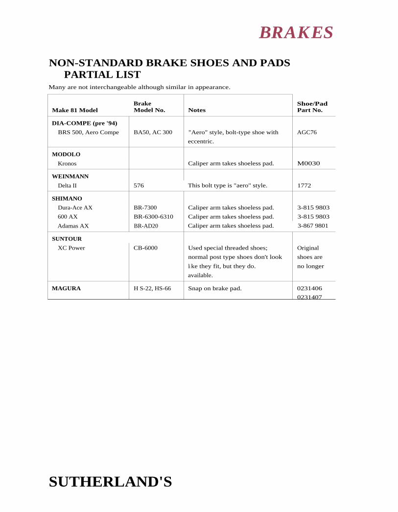
BRAKES
NON-STANDARD BRAKE SHOES AND PADSPARTIAL LIST
Many are not interchangeable although similar in appearance.
BrakeMake 81 Model Model No. Notes
Shoe/PadPart No.
DIA-COMPE (pre '94)
BRS 500, Aero Compe BA50, AC 300 "Aero" style, bolt-type shoe with
eccentric.
AGC76
MODOLO
Kronos Caliper arm takes shoeless pad. M0030
WEINMANN
Delta II 576 This bolt type is "aero" style. 1772
SHIMANO
Dura-Ace AX BR-7300 Caliper arm takes shoeless pad. 3-815 9803
600 AX BR-6300-6310 Caliper arm takes shoeless pad. 3-815 9803
Adamas AX BR-AD20 Caliper arm takes shoeless pad. 3-867 9801
SUNTOUR
XC Power CB-6000 Used special threaded shoes;
normal post type shoes don't look
li ke they fit, but they do.
available.
Original
shoes are
no longer
MAGURA H S-22, HS-66 Snap on brake pad. 0231406
0231407
SUTHERLAND'S

Make El ModelBrakeModel No. Notes
Straddle CablePart No.
CHANG STAR 880A, 860A double-headed straddle cables (See Diu-Compe980 below.)
CLB
all cantilevers
CLB-1, -2, Racing
double-headed straddle cables
double-headed straddle cables
18201, 18202, 18203,
18204, 1 8205
DIA - COMPE
New Gran-Compe
Advantage—U-brake
450
610, 750
960, 980
990
double-headed straddle cables
with tiny heads
double-headed straddle cables
double-headed straddle cables
single-ended cable with barrel end and grip
1273.100
1270.100, -.100
1271.250, -.300
1275.120
GRAFTON - all models
IRD - all U-brakes
double-headed straddle cables
unique, double-headed straddle cables
LEE CHI 700A double-headed straddle cables see Dia-Compe 980
MAFAC
GT
Competition, 2000,
Cantilevers, Racer, Raid
unique, double-headed straddle cables
double-headed straddle cables
straddle cable with a tiny head & spool
5469E
4069
(See Weil:moonCC-420 below.)
MODOLO
Cross
Kronos
two identical, double-headed straddle
cables per brake
Kronos levers require special ferrule
M0376, M0377,
M0413 (bridge)
M0156
610, 750
NCL 620
GRB 430
CC-420
double-headed straddle cables
integrated straddle bridge/cables
integrated straddle bridge/cables
straddle cable with a tiny head & spool
1270.110, -.150
1242.120, -.140, -.170
1242.120, -.140, -.170
1 276.350 & 1277
WEINMANN
Vainqueur
BRAKES
NON-STANDARD BRAKE STRADDLE CABLESPARTIAL LIST
Many are not interchangeable although similar in appearance.
SUTHERLAND'S

CONTENTS
14HEADSETS
STEMSHANDLEBARS
HeadsetsStandards
Threads ....................................... 2
Press fit dimension .................... 2
Stem 0.0. .................................. 2
Markings - threaded .................... 3........... StemsPress fit dimensions and Clamp hole diameter ................. 20
tolerances .................................. 4............Mountain bike ............................. 20
Stack height .................................... 5
Mixing parts within stacks .....5-6
Incorrect steerer length ............... 6
Headset binding ........................ 6-7
Threadless HeadsetsSteerer tube length formula ...... 8
Headset ChartsKey ..................................................... 9
Charts ...................................... 1 0-16
Threadless system chart ........... 1 7
O'rings ............................................ 1 8
Locknuts ......................................... 1 8
Notes .............................................. 1 9
Worksheet ............................... 21-22
SUTHERLAND'S
HandlebarsDiameters ...................................... 20
Mountain bike ............................. 20

1501
English 2, 3
Italian 2
French
1" (25.4mm)
x 24 TPI
1" (25.4mm)
x 24 TPI
1" (25.4mm)
x 24 TPI5
25mm
x 1.0mm
Austrian 2, 6
(East German)
26mm
x 1.0mm
1" (25.4mm)
x 24 TPI
BMX
Raleigh 2, 7
Chater Lea
1" (25.4mm)
x 26 TPI
31/32"
x 30 TPI
Alex Moulton 1" (25.4mm)
x 24 TPI
HEADSETS, STEMS, HANDLEBARS
HEADSET STANDARDS
ThreadStandard
Japanese(jis)2
Professional/
Campagnolo
1 1/8" OS
(oversize)
Standard
U.S.A.2, 4
1 1/4" OS
Thread Sizes
1" (25.4mm)
x 24 TPI
1" (25.4mm)
x 24 TPI
1 1/4" (31.8mm)
x 26 TPI
11/8" (28.6mm)
x 26 TPI
1" (25.4mm)
x 24 TPI
Press Fit Dimension
PressedHeadTube RaceOutsideDiameterK*
HeadTubeReamerSize
CrownRaceInsideDiameterL*
CrownRaceSeatCutterDiameter
StemOutsideDiameter
CommonUse
30.0mm 29.8mm 27.0mm 27.1mm 22.2mm
30.2mm 30.0mm 26.4mm 26.5mm 22.2mm High
quality
34.0mm 33.8mm 30.0mm
(25.4mm)
30.1mm Mountain,
Tandem
37.0mm 36.8mm 33.0mm(28.6mm)
33.1mm11/8
" Mountain,
Tandem
varies varies .833"(21.15mm)
Lower-
priced
30.0mm 29.8mm 22.2mm
30.0mm 29.8mm 27.0mm26.5mm
27.1mm26.6mm
22.2mm
30.2mm 30.0mm 27.0mm 2
26.5mm
27.1mm26.6mm
22.2mm
30.2mm 30.0mm 27.0mm 2
26.5mm
27.1mm26.6mm
22.0mm
30.8mm 30.6mm 26.7mm 26.8mm 22.0mm Some Sears
models6
32.7mm 32.5mm 26.4mm 26.5mm 21.15mm Most
models
30.2mm 30.0mm 27.0 2, 7 27.1mm See notes2, 7
30.0mm 8
36.4mm 829.8mm36.2mm
29.5mm 29.6mm 22.2mm Moulton
MK III
& Earlier
SUTHERLAND'S

HEADSETS, STEMS, HANDLEBARS
HEADSET STANDARDS (CONT'D)
Notes:* (See "Headset chart Key," page 14-9.) The numbers in these columns are nominal dimen-
sions; the races' actual dimensions vary, depending on quality and manufacturing variations;(see "Headset Press Fit Dimensions fi Tolerances," page 14-4.)
1 See Appendix for more details on ISO Standards.
2 Professional models are often manufactured using Professional/Campagnolo standard.
3 Includes Dunelt and Phillips prior to 1963; after 1963, see Raleigh.
4 Higher-priced models are often manufactured using Japanese or Professional/Campagnolostandards.
5 Frequently marked 25.4 x 24F.
6 Found on Scars models made by Steyr of Austria.
7 Raleigh, Rudge, Humber and brands made by Raleigh in Nottingham after 1963. Brands madeby Raleigh that had a 71 or 76mm bottom bracket shell generally used 26 TPI on the headset
as well as the bottom bracket. Bikes with 67 or 68mm shells used 24 TPI in both the headsetand bottom bracket.
8 Lipper and lower head tube races differ in size (head tube is tapered).
MARKINGS ON THREADED HEADSET PARTSCampagnolo, Dura Ace, Tange, Levin Stronglight S5 Zeus
and other marked headsets as follows:
English 1" x 24 TPl ENGLAND English 25.4 x 1.058 English BSCItalian 25.4 x 24 F ITALY French 25 x 1 French no markFrench 25 x 1.00 FRANCE
ID ID check with a thread pitch gauge will separate the French from other headsets and forks. Italianand English/Japanese steering columns have the same diameter and number of threads per inch.
The thread profile is, however, slightly different. (See Appendix on measuring threads.) In
practice these sizes are interchangeable.
JUVENILE: Most juvenile bikes use standard headset threading. Some, however, use the following:
Lnglish 7/8" x 24 TPIFrench 23mm x 1.0mmItalian 22.2mm x 24TPI
TANDEMS: Tandems are currently using oversized headsets. In the past many tandems used
standard headsets. Some, however, use 28mm x 1.0mm. Older English tandems used 1 1/8" x
26TPI which was also used on motorcycles.
OTHER: Some older English headsets (Chater Lea) were 31/32" x 30 TPI .
SUTHERLAND'S

Inside Head Tube
c=r HEADSETS, STEMS, HANDLEBARSHEADSET PRESS FIT DIMENSIONS AND TOLERANCES
Head tube reamers are sized 0.2mm (.008") smaller
than the pressed race O.D. standards. (See chart onpage 14-25.)
Steel pressed races should be 0.15mm - 0.20mm (.006"
-.004"1larger than inside the head tube. The races fit
sizes up to 0.25mm (.010") larger than inside the head
tube. Take care as an extra large pressed race may distort
the head tube, making the next pressed race fit loosely.
Aluminum pressed races need special care: de-burr
inside the head tube edge and grease the parts. This will
prevent raising a burr on the pressed race as it is inserted
into the head tube. Aluminum pressed races should he
0.10mm – 0.15(.004" + .006") larger than the head tube.
Crown race seat cutters come in sizes 0.1mm (.004") larg-
er than the crown race I.D. standards. (See page 14-2.)
Medium to low quality steel crown races should be
0.05mm to 0.15mm (.002" to .006") smaller than the
crown race seat.
High quality steel crown races should be less than
0.1 mm (.004") smaller.
Crown Race Seat - - -
SUTHERLAND'S

HEADSETS, STEMS, HANDLEBARS
HEADSET BINDING CAUSES1. Bent fork, head tube or steering column.
2. I mproperly milled head tube and/or crown race seat.
3. Poor fitting parts.
4. Worn or damaged parts.
S. Dirt, chips or other contamination.
6. Cross threaded, crooked, or wrong threads.
7. Poor adjustment.
8. Too many balls.
9. Wrong size balls.
10. No lubrication.
11. Poor quality headset—some aren't meant to work.
STACK HEIGHT
REPLACING STACKSThe "Fit" of a headset is so complicated that an exact replacement unit should be used unless there
is a very good reason for using a different type. In most worn-out headsets, only the lower races are
i mpaired. The chances of running into problems during replacement are minimized if only the
"lower stack" is replaced. The top stack usually outlasts the lower stack by 2 to 1 (or more).
Replacing the lower stack—Points to check1. Total height of t he replacement stack.
2. Crown race 1.1). (inside diameter) and the crown race seat should be compatible sizes.(See page 14-4.) Be sure to note if crown race has a shoulder that will prevent it
from seating properly.
3. Lower pressed race diameters should be .2mm larger than the inside head tube. Themilled portion inside the head tube must be deep enough.
Replacing the top stack—Points to check1. Threads of screwed race and locknut must match threads of steering column.
2. Total height of replacement stack. Don't forget brake hanger thickness.
3. Upper pressed head tube race diameter and head tube inside diameter should be compati-
ble sizes. (See page 144.) The milled portion inside the head tube must be deep enough.
4. Lock washer or brake hanger diameter and locking device must be compatible withgrooves or flats in steering column as well as with column diameter.
S. Stem must tit in hole in top locknut.
SUTHERLAND'S

HEADSETS, STEMS, HANDLEBARS
STACK HEIGHTS(CONT)
Replacing the top stack—Points to check (cont'd)Campagnolo aluminum headset pressed head tube races have a radiused edge where it mates
with the inside edge of the head tube. The Campagnolo head tube cutter cuts the head tube to
match this radiused portion of the head tube race. When installing aluminum headsets be sure
to bevel the inside edge of the head tube slightly with a hard deburring tool or file.
MIXING PARTS WITHIN STACKSThere is a risk of incompatibility when mixing headset parts, and the practice should be avoided
when possible. However, with care, mixing parts can work. Use the following factors to catch
problems early in the job.
1. Are the parts of a similar design? For example, you can't replace a Peugeot screwed
race with a Campagnolo screwed race.
2. Are mating parts designed to use the same size and number of halls?
3. Do the parts nest properly? Most headsets are designed so that the cups and cones
overlap slightly
to help keep dirt out.
4. Will the center pull brake hanger fit properly? Some will not seat properly without
washers or different parts.
Try it. Before installing a mixed headset, try it out off the bike (or half off the bike if it's easier).
First put the cup and cone pieces together without the balls to make sure that they nest. Then try
the fit again with balls. Under pressure the parts should rotate smoothly on each other; and
although they can rock slightly, they should not feel unstable. This also gives you a chance to
check the stack heights.
If possible, avoid mixing a high and low quality race in one hearing since performance and relia-
bility will be limited by the low quality part. Using one high quality stack (both races) in a low
quality headset can give greatly improved performance, especially if the lower, more heavily
loaded stack is the good one.
I NCORRECT STEERER LENGTHSteerer too short )Fop locknut must engage at least 3 full turns on good threads).
1. Remove any extra locknuts or spacers (be sure brake hanger still clears headset).
2. Find a headset with shorter stacks.
3. If the bicycle was assembled correctly in the first place and the fork isn't absolutely
too short, enough metal can be milled from the top and bottom of the head tube to
accommodate a thicker headset. Milling the frame is time consuming but preferable
to stripping the end of the steerer.
4. Change to side-pull brakes that don't require brake cable hanger.
SUTHERLAND'S
eft*
HEADSETS, STEMS, HANDLEBARS
INCORRECT STEERER LENGTH (CONT'D)Steerer too long.
1. Add extra lockwasher.
2. Cut or file shorter.
3. Use a taller locknut.
TIPS AND PROBLEMS TO AVIODWhen cutting a steerer tube, use a threaded fork miter block to insure the cut is square and thethreads are clean. If you don't have a miter block, run a screwed race on below where you intendto cut. When you are finished you can unscrew the race to clean up the threads.
Whenever a headset is disassembled, it is good practice to replace all the balls. Headset balls carry
the load and road shocks without rolling and are therefore likely to become deformed.
Putting a Campagnolo headset in a bike designed for another headset frequently results in a too-short steerer. One solution is to mount a Campagnolo track headset. Another is to mill the upperand lower ends of the head tube by a distance equal to the difference in thicknesses. Using eithermethod, the frame will remain level and the steering geometry won't be changed.
Lockwashers should just fit over the steerer. If the hole is too large, the locking tang or flat willtend to rotate and damage the threads. Avoid the temptation to use an English or Italian lock-washer on a French bike. The flat can be filed to do the job of a tang. Don't file the lockwasherround. It must have a tang or flat, to do its job. You can simply use the old washer.
The cup and cone design of most headsets allows the bearing to function even with a slightlycrooked steerer, steerer thread, or mis-milled frame or fork. Headsets with cones which are trulyconical or which have u-shaped or v-shaped races require more critical alignment if the races aregoing to contact all the balls without having tight spots.
When mounting FT headsets or Stronglight V-4, or others of this type, it is important to mill the
head tube and crown race seat to ensure the best performance from these designs.
If the frame is straight and the original headset binds, it is more likely due to imprecision inmilling the frame than the original imprecision of the headset. Changing headsets withoutmilling the head tubes and fork crown is not recommended.
On some frames, usually less expensive French and some Japanese, the ends of the head tube aremilled slightly concave. This is to give better support to the pressed races of an inexpensiveheadset. If you plan to change to a more expensive headset, the head tube should be milled flat
to match the new headset. Good headsets are usually thicker than cheap ones, so milling thehead tube will also prevent the steering column from being too short. Do not mill the head tube
too much, you may weaken it. Especially head tubes with lugs.
SUTHERLAND'S

Spacers –
Seal —
Compression Ring -
Flexible Seal
en.HEADSETS, STEMS, HANDLEBARS
THREADLESS SYSTEMS1. The frame and fork of the threadless system must he prepped before installation. lie head tube
and fork crown race should be milled just as you would for a threaded headset.
2. The old steerer tube is most likely too short for the system. Manufacturers supply a standard
12" tube especially for the front suspension threadless systems. These tubes are not threaded.
3. The length of the steerer tube protruding from t he the top of the head tube (See Figure 1)should be the stack height plus the stem height plus optional spacers minus 3mm. Also, cablehanger, retention washers, and spacer rings for stein height adjustment may be included.
4. Press the star nut inside the steerer tube 15mm below the top of the tube. This can be done
using a Park threadless nut setter, or you can partially screw in the adjusting bolt and tap thetop of the screw gently to place the star nut.
5. To set the proper preload of the bearing torque thetop alien adjusting bolt to approximately 22 in. lbs.or tighten until all play is removed from the head-set but it still rotates freely.
6. Tighten the stem pinch bolts approximately 130 in.lbs. It is very important that the stem is secure!
Steerer Tube Length Formula
Example:
Head tube length + 127mm
Headset stack height + 28.2mm
Stem height + 45mm
Optional spacer height 2mm
Pre-load compression gap (3.0)
Total steerer tube length 199.2mm
SUTHERLAND'S

Figure 1:With the forkcrown race seatagainst the bottomof the head tube,the length of steerertube protrudingfrom the top shouldbe about 2mmless than A.
Screwedrace
UpperheadtubepressedraceK
D Locknut
V G Washer
A• ,
SLower
stack
-4-- F
E
Lowerheadtubepressedrace
M Crownrace
L
Upper stack minuslocknut lip thickness
HEADSET CHART KEYA Upper and lower stack height minus locknut
lip thickness
B Upper stack height minus locknut lip thickness
C Lower stack height
D Locknut height minus lip thickness
E Locknut stem hole — generally 0.2mm or more
larger than the stem diameter. (See page 14-2for stem diameters.)
F Locknut flat dimension — F indicates wrench
flats, Ø indicates diameter with pin-tool holes
in edge
G Washer thickness (over teeth, if any)
H Washer locking method. French use flats.
Others use tang.
Screwed race dimension — F indicates wrench
flats, e indicates diameter with pin-tool holes
or notches
K Upper and lower head tube pressed race diameter
L Crown race seat diameter. (See page 14-2.)
M Crown race seat depth
N Upper race — number and size of loose balls
O lower race - number and size of loose balls

0
Make &Model
ModelNo. A B C D H* M 0*
AMERICAN CLASSIC
AVOCET
• Sealed
BIANCHI (old)
("U-race")
CAMPAGNOLO
• Record (1990) - w/seal
• (C-)Record - 1982-89
• (C-)Record - 1982-89
• Super Record-Road
Super Record-Track
• Nuovo Record(pre-'85) Victory,Triomphe - Road
• Nuovo Record Track(pre-1985),Gran Sport
• Chorus, Croce, D'Aune
• Athena
• Xenon
• Euclid, Centaur
• Centaur (steel)
• Olympus (alloy)
• Olympus (steel)
OVERSIZED MODELS
• Record OR 1 /18"
• Euclid 1'/4"
CANNONDALE
• Delta V
• Super V
CYCLE PRO
• Deluxe Sealed
• MX alloy (Hatta)
1"1 W
35.8
35.8
23.9
25.4
11.9
12.9
1 9.49
21.79
allen
allen
5.1
5.1
cartridge
cartridge
cartridge
cartridge
42.0 27.2 14.8 5.2 32 F 4.1' 2 32 F 11.9 sealed sealed
46.7 29.7 1 7 9 32ip 2.0 key 320 9.9 31 - 1 W 311A3"
41.4 26.2 15.2 7.3 32 F .44 key 32 F 7.5 22-3/16" 22-3/16"
Road 41.4 26.2 15.2 7.3 32 F .44 key 32 F 7.5 25-Y321' 25-'/32"
Track 38.5 26.3 12.2 7.3 32 F . 34 key 32 F 5.6 25-5/32" 25-5/32"
4041 42.2 27.2 1 5.0 7.0 32 F 4.0 key 32 F 7.9 22-3/16" 22-3/16"
4141 33.7 22.3 11.4 7.0 32 F 2.1 key 32 F 6.0 25-5/32" 25-5/32"
1 039 39.1 24.6 1 4.5 5.7 32 F 2.1 key 32 F 9.9 22-3/161' 22-3/46"
1 040/A 33.7 22.3 11.4 5.7 32 F 2.1 key 32 F 7.0 25-5/32" 25-5/32"1 040
41.2 25.6 15.6 7.1 32 F .3 4 key 32 F 7.8 22-3/16" 22-1/16"
41.0 25.8 1 5.2 7.2 32 F .4 4 key 32 F 7.5 R19-3/16" R19-3/16"
39.5 24.5 1 5.0 32 F key 32 F 22-3/16" 22-3/16"
40.6 25.6 15.0 7.2 32 F 2.2 key 32 F 10.0 22-3/16" 22-3/16"
40.7 26.0 14.7
40.5 25.5 15.0 32 F key 32 F 22-3/46" 22-3/16"
39.0 24.3 1 4.7 32 F key 32 F 22-3/46" 22-3/16"
HS-010R 36.2 23.3 1 3.0 7.4 36 F 1.5 tang 36 F 6.5 R22- 5/12" R22-5/321'
36. 23.3 1 3.0 8.5 40 F 2.0 tang 40 F 6.5 R22-Y32" R22-5/321'
20.3 1 0.1 1 0.1 cart.B543 cart.B543
20.3 1 0.1 1 0.1 cart.B543 cart.B543
63-02-501 36.7 24.7 12.0 6.7 32 F 2.0 key 32 F 8.1 25-5/32" 25 -5/32"
63-02-230 41.3 28.3 13.0 9.1 30 F 2.6 key 30 F 5.9 22- 3/16" 22-3/16"
(See page 14-19 for notes on this chart.)
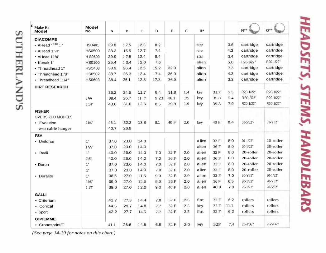
I Make EaModel
ModelNo. A B C D F G H*
DIACOMPE
• AHead ' 516 1 " HSO401 29.8 1 7.5 1 2.3 8.2 star 3.6
• AHead 1 V8" HS0500 28.2 15.5 12.7 7.4 star 4.3
• AHead 11/4" H S0600 29.9 1 7.5 12.4 8.4 star 3.4
• Konak 1" HS0100 25.4 1 3.4 1 2.0 7.6 alien 5.8
• Threadhead 1" HSO403 38.9 26.4 1 2.5 15.2 32.0 alien 3.3
• Threadhead 1'/8" HS0502 38.7 26.3 1 2.4 1 7.4 36.0 alien 4.3
• Threadhead 11/4" HS0603 38.4 26.1 12.3 17.3 36.0 alien 3.3
DIRT RESEARCH36.2 24.5 11.7 8.4 31.8 1.4 key 31.7 5.5
1 W 38.4 26.7 11 7 9.23 36.1 .75 key 35.8 5.4
1 1/4" 43.6 31.0 1 2.6 8.5 39.9 1.9 key 39.8 7.0
FISHER
OVERSIZED MODELS
• Evolution 11/4" 46.1 32.3 13.8 8.1 40 F 2.0 key 40 F 8.4
w/o cable hanger 40.7 26.9
FSA
• Uniforce 1" 37.0 23.0 14.0 a lien 32 F 8.0
1 W 37.0 23.0 1 4.0 alien 36 F 8.0
• Radii 1" 40.0 26.0 14.0 7.0 32 F 2.0 alien 32 F 8.0
11/811 40.0 26.0 1 4.0 7.0 36 F 2.0 alien 36 F 8.0
• Duron 1" 37.0 23.0 1 4.0 7.0 32 F 2.0 allen 32 F 8.0
1" 37.0 23.0 1 4.0 7.0 32 F 2.0 a lien 32 F 8.0
• Duralite 1" 38.5 27.0 11.5 9.0 32 F 2.0 alien 32 F 7.0
11/8" 39.0 27.0 12.0 9.0 36 F 2.0 alien 36 F 6.5
1 1/4" 39.0 27.0 1 2.0 9.0 40 F 2.0 alien 40.0 7.0
GALLI
• Criterium 41.7 27.3 1 4.4 7.8 32 F 2.5 flat 32 F 6.2
• Conical 44.5 29.7 1 4.8 7.7 32 F 2.5 key 32 F 11.1
• Sport 42.2 27.7 14.5 7.7 32 F 2.5 flat 32 F 6.2
GIPIEMME
• Cronosprint/E 41.1 26.6 1 4.5 6.9 32 F 2.0 key 32F 7.4
cartridge cartridge
cartridge cartridge
cartridge cartridge
R20-1/22" R20-1/22"
cartridge cartridge
cartridge cartridge
cartridge cartridge
R20-1/22" R20-1/22"
R20- 5132" R20-1/22"
R20-1/22" R20-1/22"
31-5/32"- 31-Y32"
20-1/22"
20-1/22"
20-roller
20-roller
20-roller
20-roller
20-Y32"
20-1/22"
20-1/22"
20-roller
20-roller
20-roller
20-roller
20-roller
20-roller
20-1/22"
20-Y32"
20-5/32"
rollers
rollers
rollers
rollers
rollers
rollers
25-5/32"25-Y32"
(See page 14-19 for notes on this chart.)

H*Make ix ModelModel No. A B C
GT• Epoch BMX Super 6 43.0 31.6 11.4 10.6 30 F 1.7 key 6, 7 6.5 22-3A6" 22-3/k,"
HATTA
• MX-II 39.9 29.0 1 0.9 1 0.0 30 F 2.6 key 30 F 6.0 22-3/46" 22-3/46"
KING'
• Pre-93 Standard 1" 43.5 28.8 14.7 8.2 32 F 32 F 5.2 sealed sealed
• Pre-93 Short Stack 35.9 23.9 12.0 8.0 32 F 32 F 3.8 sealed sealed
• Standard 1" 80100 41 26.5 14.5 9.5 32F grip 32F 5.1 cartridge cartridge
• Short Stack 1" 82100 33 20.8 1 2.2 9.5 32F grip 32F 3.8 cartridge cartridge
• BMX 81100 39.1 25.6 1 3.5 9.5 32F grip 32F 5.1 cartridge cartridge
• OS 11/4" 84100 36 23.1 1 2.9 9.5 36F grip 32F 4.6 cartridge cartridge
• OS 1W' 85100 40 25.8 14.2 9.5 40F grip 40F 4.6 cartridge cartridge
KONA
• Race Light Impact 11/s" 34.8 22.4 12.4 1 7.9 alien 6.0 22-V32" 15-'/4"
• Control Center 1 1/4" 34.3 22.0 12.3 1 9.5 alien 6.3 22-Y32" 15-1/4"
MAVIC
• 305 40.4 26.9 13.5 9 32 F alleri° 9 6.0 31-1/8" 31-W
• 315 45.3 31.3 913.5 32 F 10 9 6.0 31-Vs" 31 -Vs"
• 311 42.4 28.8 1 3.6 8.7 11 2.0 flat 11 6.3 31 -Vs" 31-Vs"
• 312 42.5 28.8 13.7 8.6 11 2.0 flat 11 6.3 31-Vs" 31-Vs"
• 315 1" 46.3 32.9 1 3.4 30.7 32 F 6.0 R22-1/4" R22-W
• 316 VVT - ATB 1 1/4" 46.1 32.8 13.3 30.5 36 F alien 6.0 R25-1/4" R25-1/2"
• 317 VVT - ATB 1 1/4" 46.1 32.6 13.5 30.3 36 F alien 6.0 R25-1/4” R25-Vs"
12(ALEX) MOULTON Pre-1980 37.2 26.4 1 0.8 9.8 31 F13 2.9 5.2 3 0 _ 1/21,14 37?/ II14
ODESSEY
• Toro Pro 1" 35.4 22.0 13.4 5.5 32 F 4 key 32 F 8.3 20-roller 20-roller
1 1/4" 34.1 21.1 13.0 5.5 36 F 4 key 36 F 8.2 22-roller 22-roller
OFMEGA
• Ofmega 39.6 28.4 11.2 1 0.3 32 F 2.0 key 32 F 6.2 26-V32" 26-5/3Z
• Competizione 40.9 26.2 1 4.7 7.4 32 F 2.2 key 32 F 9.1 22-3/46" 223/4"
• Sport 38.8 27.0 11.8 8.9 32 F 1.3 key 32 F 6.6 26-s/v" 26-Y32"
(See page 14-19 for notes on this chart.)

0**
311/s"
22-roller
22-roller
22-roller
26-5/32"
cart.6807
25-5/12"
25-V12"
26-Y1,2"
22-3/16" 26
22-3A6"26
R22-1/16"
25-5/32"
22-3/16,"
22-Via"
25-5/32"
cart.9803
22-3/16"
22-3/16"
2 2 -Vib"
cart.9803
25-5/32"
22-Via"
22-3/16"
25-s/12"
Make SE ModelModel No. A D F G 11* 1
OMAS
• Art 120 40.1 26.6 13.5 7.0 32 F 1.6 key 32 F 8.1 31-'/s"
ONZA fi
• Mongo II 37.0 23.5 13.5 8.8 32 F 2.5 key 7.4 22-roller
1 W 38.7 22.5 16.2 13.5 38 F ailed° 7.6 22-roller
11/4" 38.7 22.5 16.2 1 4.1 41 F alien 7.6 22-roller
PEUGEOT 38.5 26.5 1 2.0 1 0.8 32 F 2.5 key 45.79 7.0 26-5/3z"
RACE FACE 11/s" 29.1 15.8 13.3 5.0 star 5.0 cart.6807
RALEIGH
• Rat 101 37.0 23.7 13.3 8.2 30.2 F 2.7 41.3 F 6.1 25-5/12"
• Pat 803 41.1 28.1 13.0 12.8 30.4 F 2.7 41.2 F 6.0 25-Via"
• Aletet 36.1 24.6 11.5 7.3 30.6 F 3.3 42.0 F 6.7 26-5/31
RITCHEY
• Logic 34.4 22.0 1 2.3 6.8 32 F 1.4" key 32 F 6.8 31 _ ys i, 26
• Logic Comp 34.0 22.0 12.0 6.6 32 F 1.3" key 32 F 6.8 31 -'/ 26
• Logic Expert 1 1/4" 35.2 24.0 11.2 7.0 40 F 1.7 key 40 F 7.5 R28-1/8"
SCHWINN
n Deluxe'? 36.7 26.4 10.3 1 0.9 30 F 2.0 key 41.2(5 5.6 25-5/31
• Standard's 36.9 26.9 1 0.0 1 0.9 30 F 2.0 key 45.39 5.8 22-3/16"( Made in U.S.A.)
• Standard 56-710 39.4 27.9 11.5 11.0 30 F 2.0 key 7 6.0 22- 3/i6"( Made in Japan)
SHUMAN° 19
• Dura-Ace HP-7600 31.0 19.5 11.5 32 F key 32 F 25-5/32"
Dura-Ace HP-7410 37.6 24.1" 13.5 5.1 32 F 1.1" key 32 F 6.4 cart.9803
Dura-Ace HP-7400 36.720 23.1" 1 3.4 5.1 32 F 1 . 1 15 key 32 F 6.4 22- 3/16'
Dura Ace EX" HP-7200 37.9 23.1 2114.8 4.5 2.0 key 21 22-3/16"
Dura Ace HP-71 00 39.7 24.7 15.0 5.4 32 F 2.1 key 32 F 9.6 22- 34"
• 600 Ultegra HP-6500 37.6 24.1 13.5 32 F key 32 F cart.9803
600 Ultegra HP-6400 33.8 22.2 11.6 6.6 32 F 0.9" key 32 F 6.0 25-5/32"
600 EX HP-6207 39.9 25.1 1 4.8 21 key 21 22-3/16"
600." HP-6200 39.9 25.1 14.8 21 21 22-3/16"
• Sante HP-5000 33.4 23.3 1 0.1 8.5 30 F22 2 . 823 key 32 F 5.9 25- 5/3i'

Make EzModel
ModelNo. A B C D F G H*
SHIMANO (contd)"1 05 SC HP-1055 33.3 21.6 11.7 8.0 32 F 0.6 15 tang 32 F 6.7
1 05" HP-1050 32.7 21.2 11.5 32 F tang 32 F
XTR HP-M900 34.3 22.8 11.5 32 F tang 32 F
Deore XT HP - M 740 37.6 24.1 1 3.5 32 tang 32 F
Deore XT HP-M735 34.0 22.4 11.6 7.0 32 F 2.0 tang 32 F 5.4
Deore XT HP-M730 32.1 20.6 11.5 6.5 32 F 0.1 15 tang 32 F 6.7
Deore DX HP-M650 33.8 22.2 11.6 6.6 32 F 1.9 tang 32 F 5.4
Deore LX-HD-C HP-M563 37.6 24.1 13.5 32 F tang 32 F
Deore HP-MT60 32.5 20.8 11.7 5.9 32 F 2.0 tang 32 F 6.7
STX-SE 1" HP-MC30 37.6 24.1 1 3.5 32 F tang 32 F
Alivio 1" 34.4 22.7 11.5 5.9 32F 1.9 tang 32F 6.7
Exage HP-R500 32.7 22_0 11.5 32 F tang 32 F
Exage HP-A450 33.5 22.0 11.5 32 F tang 32 F
Exage HP-M450 33.5 22.0 11.5 32 F tang 32 F
Exage HP-M350 33.5 22.0 11.5 32 F tang 32 F
Le Tour (OEM- 42.5 31.5 11.0 1 0.9 30 F 1.9 tang 45 0 6.7Schwinn)
OVERSIZED MODELS
XTR 1 1/2" HP-M901 343 22.8 11.5 36 F tang 36 F
XTR I 1/4" HP-M902 40.3 27.3 1 3.0 40 F tang 40 F
Deore XT 11/8" HP-M741 37.6 24.1 13.5 36 F tang 36 F
Deore XT 1 1/4" HP-M 742 39.9 26.4 13.5 40 F tang 40 F
Deore XT 11/4" HP-M 737 40.3 27.3 13.0 40 F tang 40 F
Deore XT 11/8" HP-M736 33.5 22.0 11.5 6.7 36 F 2.0 tang 36 F 5.4
Deore DX 1 1/2" HP-M651 33.5 22.0 11.5 7.2 36 F 2.0 tang 36 F 5.4
Deore LX-HD-C 1 1/2" HP-M564 37.6 24.1 1 3.5 36 F tang 36 FSTX-SE 1 1/4" HP-MC31 37.6 24.1 13.5 36 F tang 36 F
Alivio 11/2" 33.5 22.5 11.5 6.2 36F 1.9 tang 36F 6.7
SPECIALIZED
Pro-Compact, alloy 35.3 23.4 11.9 6.0 32 F 1.1 15 tang 32 F 6.4
25- 5/32" 25-5/32"
25-5/32" 25-5/32"
R20-3/16" R20-3/16'
cart.9803 cart.9803
17-1/4" 1 7-1/4"
25- 5/32" 25-5/32"
1 7-1/4" 17-1/4"
cart.9803 cart.9803
25-5/32" 25-5/32"
cart.9803 cart.9803
R20- 5/32" R20-5/32"
25-5/32" 25-Y32"
25-5/32" 25-5/32"
25-5/32" 25-Y32"
25-Y32" 25-5/32"
25-Y32" 25-5/12"
R22-3/16" R22-3/16"
R24-3/16" R24-3/16"
cart.9802 cart.9802
cart.9802 cart.9802
22-7/32" 22-7/32"
R18-1/4" R18-1/4"
1 9-1/4" 1 9-1/4"
cart.9803 cart.9803
cart.9803 cart.9803
R22- 5/32' R22-5/32'
25- 5/32" 25-5/32"
rb
z

N**
25-Y32" 25-Y32"
R22-5/321' R22-5/32"
R 2 0 -5/32" R20-5/32"
25-5/32" 25-5/32"
25-Y3.2" 25-Y32"
25-Y32" 25-5/32"
tapered tapered
tapered tapered
roller' rollers
25-Y32" 25-Y32"
25-Y32" 25-Y32"
25-Y32" 25-Y32"
25-Y32" 25-Y32"
25-5/32" 25-5/32"
15-Yio" 15-1/46"
roller roller
R20-5/32" roller
25- 5/32" 25-5/32"
25-5/32" 25-5/3Z
R20- 5/32" R20-5/32"
R22- 5/32" R22-5/32"
R22- 5/3.2" R22-5/32"
R22-Y32" R22-Y32"
25- 5/32" 25-5/32"
25-Y32" 25-5/32"
22- 5/32" 22 5/32'
22- 5/32" 22-5/32"
(See page 14-19 for notes on this chart.)
Make Ea ModelModel No. A B C D F G H* J M
SPECIALIZED (cont'd)
• Channel-Seal, alloy 45.1 29.6 15.5 7.2 32 F 2.04 tang 32 F 1 0.2
• Pro Alloy I 1/8" 35.9 24.5 11.4 7.6 36 F 0.7 4 tang 36 F 5.4
• AV II 1 92-0410 36.9 24.4 1 2.5 6.0 32 F .9 tang 32 F 6.2
• Channel-Seal, steel 35.0 23.3 11.7 6.3 32 F 1.0 15 key 32 F 6.3
• Standard, steel 38.2 25.8 1 2.4 7.4 32 F 2.0 key 32 F 7.9
STEYR PUCH 81716 35.4 24.8 10.6 11.9 30 F 3.0 key 46.54) 6.7
STRONGLIGHT
• Delta 40.7 25.7 1 5.0 7.5 32 F 0. 64 32 F 7.6
• Mountain Delta 45.0 30.4 14.6 1 2.6 36 F 36 F 7.3
• A9 39.8 27.2 13.9 8.2 32 F 2.6 key 32 F 6.4
• V4 39.3 25.3 1 4 7.5 32 F 4.923 flat24 45d) 2max
• B10 39.5 25.6 13.9 7.5 31 F 5.3 flat 450 4.6max
• P3 34.0 22.9 11.1 6.4 28 F 4.523 flat24 450 5.2max
• 55 40.6 26.8 1 3.8 7.1 32 F 2.7 32 F 7.5
SUNTOUR
• Superbe Pro HS-SBOO 37 (' 23.5 1 3.5 6.8 F 2.1 key 32 F 7.8
TANGE-SEIKI
• BMX 39.5 27.9 11.6 11.0 30 F 2.0 key 45 F 6.0
• G-Master TR-2000 43.9 28.6 15.3 7.2 32 F 2.0 key 32 F 8.8
• Super Roller 34.3 21.1 1 3.2 6.5 32 F 0.74 tang 32 F 9.5
• Levin CD 35.8 23.6 1 2.2 6.5 32 F 1.2" key 32 F 6.9
• Levin 37.8 25.7 1 2.1 6.7 32 F 2.1 key 32 F 7.6
• Levin MTB-225 39.6 25.5 14.1 7.1 32 F 2.0 key 32 F 1 0.6
• Levin Dominas OV286CA 38.3 24.2 1 4.1 7.4 36 F 1.1" key 36 F 6.0
AP-1 OS 34.4 23.6 1 0.8 7.1 36 F 2.0 key 36 F 6.0
FOVST OS 45.7 34.7 11.0 8.0 40 F 1.115 key 40 F 8.0
• Falcon FL-250S 40.1 25.9 1 4.2 7.3 32 F 2.0 key 32 F 1 0.1
• - MA-60 36.0 25.0 11.0 9.5 32 F 4.0 23 key 247 7.1
• - AW 27 38.9 27.7 11.2 11.1 30 F 2.0 key 30 F 6.0
MX2 39.1 28.3 1 0.8 1 0.1 30 F 2.8 key 30 F 6.0

R20-5/32"
R22-5/32"
R25-5/32"
R22-3/16'
R22-3/16"
R22-3/16"
R22-3/16"
R22-3/46"
R20-5/32"
R22-5/32"
R25-Y32"
R22-3/46"
R22-3/16"
R22-3/16"
R22-3/16"
R22-3/16"
N** 0**
2 6 -3/16 " 26-3/16"
R29-Y32"
R29-5/32"
R29-5/32"
R29-5/321'
R 2 2 -5/Q"
R22-5/32"
R22-5/32"
R29-5/32"
R29-5/32"
R29-5/3.2"
R29-Y32"
R22-5/32"
R22-Y32"
R22-5/32"
cartridge cartridge
R20- 5/32" R20-5/32"
R16- 5/32" R16-5/32"
R22-Y32" R22-5/32"
R22-Y32" R22-5/32'
R22-Y32" R22-5/32"
R22- 5/32" R22-5/32"
1 5- 5/32" 1 5-5/32"
25-Y32" 25-5/32"
22- 3/ie 22-3/3f,"
22-3/36" 22-3/16"
Make EiModel
ModelNo. A B C D F G H* 1 M
TIOGA
• Road Expert 31,5 20.0 11.5
• Expert CR, Master DL 33.5 22.0 11.5
• MTB Expert, 1 37.1 25.3 11.8 7.2 32 F 2.1 key 32 F 8.0• MTB-KT-AL 40.8 26.4 14.4 7.3 32 F 2.1 key 32 F 8.2
• Beartrap 2 39.5 28.4 11.1 1 0.6 32 F 244.2" key 32 F 6.8
• MX-2 39.3 28.1 11.2 1 0.2 30 F 2.6 key 30 F 6.3• MX101 43.1 31.9 11.2 1 3.3 32 F 2.0 key 32 F 6.0• MX-600 39.3 28.1 11.2 1 0.1 30 F 1.7 key 30 F 6.1
OVERSIZED MODELS
• Avenger OS-H1 35.1 24.2 1 0.9 6.9 36 F 1.2" key 36 F 6.5
Avenger 05-H3 32.7 21.7 11.0 6.5 36 F 1.115 key 36 F 6.2
Avenger 05-H4 37.8 25.0 1 2.8 6.5 36 F 1.4'5 key 36 F 7.2
Avenger 05-H6 34.0 22.2 11.8 6.5 36 F 0.7" key 36 F 5.8
• Alchemy ALS 25 1 8.7 1 0.9 star 6.0
Alchemy AL2 25 15.6 11.9 star 7.0
Alchemy ST2 2$ 15.7 11.8 star 7.1
WHW 37.5 26 11.5 8.5 31 F 4. 123 key 24 7 5.0
WILDERNESSTRAIL BIKES
• 1" Grease Guard a 42.8 28.0 1 4.8 8.0 32 F 32 F 5.5
YST
HP-831 1 35.8 23.8 1 2.0 7.0 32 F 1.04 key 32 F 5.7
HP-8002 36.9 27.0 9.9 8.6 32 F 2.0 key 32 F 6.0
• 11/4 OS CS-707S 41.0 27.6 13.4 8.5 40 F 1.9 key 40 F 7.0
• 11/4 OS Uitralight 35.0 23.3 11.7 6.6 40 F .6" key 40 F 5.7
• 11/4 OS CS-707A 41.1 27.6 13.5 8.6 40 F 2.0 key 40 F 7.0
• 11/8 OS CS-71 7 35.1 23.3 11.8 6.4 36 F .8' s key 36 F 5.5
• MX Action 35.8 24.8 11.0 8.3 30 F 1.54 key 46 F 7.0
n Antech 8703 39.3 25.9 1 3.4 6.0 32 F 2.1 key 32 F 9.2
• BMX 39.8 28.6 11.2 8.6 30 F 2.1 key 7 6.0
ZEUS 40.7 25.8 14.9 6.4 32 F 2.0 flat 32 F 9.1

cartridge cartridge
cartridge cartridge
cartridge cartridge
cartridge cartridge
cartridge cartridge
cartridge cartridge
cartridge cartridge
cart. 6807 cart. 6807
R22- 5/32" roller pin
R22- 5/32" roller pin
R28-1/2" roller pin
R28-'/s" roller pin
22- 5/32" 22-5/32"
22-Y32" 22-5/32"
22- 5/32" 22-5/32"
Threadless
Make &Model
ModelNo. A B C D H M
DIACOMPE
• AHeaci' 5.16 1 " HSO401 29.8 1 7.5 1 2.3 8.2 star 3.6
• AHead P/8" HS0500 28.2 1 5.5 1 2.7 7.4 star 4.3
• AHead 11/4" HS0600 29.9 17.5 12.4 8.4 star 3.4
KING
• 1 1/2"5 1 6.9 1 2.9 8.0 star 4.6
• NoThreadSet 1 " 80300 34 1 9.5 14.5 star 5.1
• NoThreadSet 11/8"15 84300 28 15.1 12.9 star 4.6
• NoThreadSet 1 1/4" 85300 31.1 1 6.9 1 4.2 star 4.6
RACE FACE 11/8" 29.1 15.8 1 3.3 5.0 star
TANG E-SEIKI
• 228 - steel 1" 40.5 28.8 11.8 allen 7.3
228 - alloy 1" 41.7 28.3 13.4 alien 8.3
• 541 - steel 1 1/2" 42.8 29.9 1 3.8 alien 8.3
541 - alloy 1 W 43.2 29.9 13.3 alien 7.7
TIOGA
• Alchemy ALS _25 1 8.7 1 0.9 star* 6.0
Alchemy AL2 _ZS 15.6 11.9 star* 7.0
Alchemy ST2 _25 15.7 11.8 star* 7.1
* Suggested torque stem cap alien 4 - 1()in. lbs., max 15in. lbs.
(See page 14-8 and 14-19 for more notes on this chart.)

"0" Rings
Brand Headset Model No Approx. I.D. Approx.O.D Approx. Cross-Section
MAVIC 312 21 26 2.5
TANGE TR 2000 21 25 2
RITCHEY Logic Comp 21 25 2
STRONGLIGHT Delta (locknut) 22 25 1.5
SHIMANO HP-7400 22 26 2
TIOGA OS-H6 24 29 2
STRONGLIGHT MountainDelta (crown race)
3535
3939
1.51.5
CAMPAGNOLO Euclid 38 41 2
Locknuts
Make Ei Model Model No. F
DELTA
n HeadLock 1" 8.9 32 F allen
• HeadLock 1 1/2" 8.9 36 F alien
• HeadLock 1 1/4" 8.9 40 F alien
GORILLA
• Headlock 1" 8.0 allen
1 -ye 8.0 allen
1 N" 8.0 allen
SUGINO
• High Column 1" 30.0
1 W 30.0
TANGE
• CDS Levin 1" 6.0
(See page 14-19 for notes on this chart.)
Make Ex Model Model No. D F
WHEELS MFG.
• Growler 1" 6.0 star
1 1/8" 6.0 star
1 1/4" 6.0 star
Y ST
alloy 1" 8.0
alloy 11/8"
alloy 1 1/4" 12.0
steel r
steel 11/8' 9.0
steel 1 1/4" 12.0

(See note on page 14-8 for E expld oration)
-F 1P-1
E
HE-1 II'
D
A = B C
K
4- L
(See page 14-9 prK and L explanation)
Notes:There are more exceptions than rules here;French threaded headsets traditionally hadwashers that locked via flats, but even this varies.
** On some models it may be possible to add "onelast ball," but it is usually better to resist the temp-tation; too many halls can damage the bearing.
1. "Middle nut" replaces washer.
2. Nesting conical tapers between bearing raceand middle nut.
3. Internal wall continues up throughout bearing.
4. Washer fits almost flush in locknut.
5. Conical steel washers must be installed betweenhearings and races.
6. Has coil spring and ratchet anti-looseningmechanism.
7. Simply knurled.
8. To avoid damage to the bearings use theappropriate adapter hushing set for the follow-ing cup presses (each also includes bushing forcrown race installation):
Campagnolo King 300/CBicycle Research King 300/BVar King 300/VPPark None needed
9. Screwed race, washer and locknut are replacedby one single unit.
10. Upper Unit (see footnote #11) has split collarw/2.Smm alien bolt.
11. Requires Mavic wrenches 671 and 672 (bothare needed).
12. (See "Headset Standards," page 14-2.)
13. Closer to 1-13/64", but the Park 31mm fits nicely.
K -MTB Head Tube L -Headset Stem Pressed CrownStandards O.D. Race O.D. Race I.D. T.P.I.
1" (25 4mm) 22.2mm 30.2 or 26.4 or 2430.0mm 27.0mm
1 1/4" (28.6mm) 25.4mm 34.0mm 30.0mm 26
1 1/4 (31.8mm) 28.6mm 37.0mm 33.0mm 26
14. Note - upper and lower head tube races are dif-ferent diameters (head tube is tapered).
15. Star nut presses into steerer tube 15mm belowtop of tube.
16. Stem height can only be adjusted with spacers.
17. Head tube pressed races not identical.
18. Head tube pressed races identical.
19. Some pre-1985 Shimano headsets have a 26.36crown race - smaller than any other. To salvagea fork that these were fitted to, try using a Steinknurling tool to expand the crown race seat.
20. Supplied with extra washer (measured withonly a single washer).
21. To avoid damage to aluminum surface, use twoShimano wrenches TL-HP10. (A 32mm wrenchwill work in a pinch.)
22. Remove plastic cap to expose the locknut'swrench-flats.
23. Serrated.
24. Washer locks to both fork and screwed race.When adjusting headset, washer must be lifted3mm so as to disengage screwed race.
25. Stack height usually ranges between 33-44nimfor star locking headsets.
26. Note difference in ball size between upper andlower races.

Standard Center Diameter Notes
ISO 25.4mm (1")
English 25.4mm, 23.8mm(1", 15/16")
French 25.0mm, 23.5mm
Italian 25.0mm, 23.5mm
Generally 23.8 is found on 3-speedand coaster brake bikes.
Belleri - 26.0, Mavic - 26.0
Exceptions: Cinelli - 26.4,TTT - 26.0, Modolo - 26.0,some Italmanubri - 25.6
Exception: Dura-Ace stems - 26.0*,Cinelli Copies - 26.4,other quality bars - 26.0
Japanese 25.4mm
U.S. 25.4min Exception: Schwinn used 15/16"on Randonneur bars in 1971
Headset Size Stem O.D.
22.2mm (7/8")
25.4mm (1")
28.6mm (1'/8")1 1 3/4"
T 1"
HEADSETS, STEMS, HANDLEBARS
HANDLEBARS—STEMSHandlebar Diameters -Brake Clamp, Grip and Clip-on Diameters22.0mm Italy, Germany, Switzerland, Northern Europe (also children's handlebars in France)
22.2mm England, U.S. steel, BMX
23.5mm France, Belgium, Spain, North Africa
23.8mm England, U.S. alloy
24.0mm Belleri, Mavic, Modolo, many Cinelli-style bars
24.2mm Cinelli
Road Bike Handlebar Center Diameters -Stem Clamp Hole DiameterThese figures can serve only as a rough guide. No hard and fast rules can be made.
* Dura-Ace stems can accept 25.4 bars by changing the internal push-plate. Likewise the 600
model stems can be changed to 26.0.
Other exceptions: Titan makes 27mm and 25in m centers. The 27mm center fits only Titan stems.
MOUNTAIN BIKE HANDLEBARS STEMSHandlebars on mountain bikes are generally 22.2mm in diameter with a 25.4mm (1") center.
Stems come in three standard diameters (22.2mm), (25.4mm), (28.6mm). (See 14-2 for stem to
steerer tube fit.) Tandem stoker stems generally have a 25.4mm center clamp and fit seat post
sizes 26.8, 27.2, 28.6, 29.8mm.
Standard Mountain Bike Stem Diameters
SUTHERLAND'S

HEADSETS, STEMS, HANDLEBARS 7
SUTHERLAND'S

HEADSETS, STEMS, HANDLEBARS
0
C)
z
2
1.,
u.
a
L.)
co
<
7.n
a a
Ez
0 _
or cil..v 10ta 0
22
SUTHERLAND'S

CONTENTS
ISSUSPENSION
FORKSand FRAMES
About Suspension ForksAbout ................................................ 2
Types of forks
Slider-telescoping .................... 2
Linkage/pivot .................................. 2
Glossary ......................................... 3-4
Types of suspension
Coil sprung ............................... 5
Air/oil sprung ........................... 6
Elastomer sprung .................... 7
Parts of a suspension forkSteerer tube .............................. 7Crown ....................................... 8Fork brace (brake bridge) ....... 8
Stanchions (upper legs) .......... 8
Seals ......................................... 9
Sliders (lower legs) .................. 9
Bushings .................................. 9
Design Elements-Service NotesHow to read charts .................. 1 0
Makes ............................. 11-51
Troubleshooting charts ....... 52 55
Tire clearance ........................... 55
Down tube clearance ............... 55
FramesTubing outside diameters ........ 56
Gear hangers
Thread sizes ......................... 57
Rear drop-out threads .......... 57
Replacing forks ............................ 57
Factors that affect handlingRake ..................................... 57
Rigidity ................................. 57
Length .................................. 58
Factors that affect fitWheel ................................... 58Frame ................................... 58
Threads ................................ 58Stem .................................... 58
Brake fit ................................ 58
Headset fit ........................... 58
Seat post sizes ............................. 59
Unusual seat post sizes ............. 60
SUTHERLAND'S

SUSPENSION FORKS
[iABOUT SUSPENSION FORKSSuspension forks need overhauling or maintenance specific to each manufacturer. Maintenance
will he needed after heavy off-road use, damage from accidents, and after normal use for long
periods. Most forks need to he taken off the bicycle for service. (Customizing the fork is not rec-ommended; the warranty will he voided,) Typical service and repair would apply to these four
main types of suspension: 1. Coil Sprung, 2. Elastomer, 3. Air/Oil, and 4. Linkage.
TYPES OF FRONT SUSPENSION FORKS
Slider-Telescoping Type Forks(Includes Air/Oil, Elastomer, and Spring)
Common in motorcycle suspensions, the forks' sliders — the lower legs —
steerer tube are usually connected at the bottom to the front wheel axle, and at thetop they slide over the stanchions of the upper legs. These in turn are
fork crownconnected to the fork crown and steerer.
This type of fork is best for situations where large travel of the suspen-sion is needed; these will accommodate big humps. Slider forks providestraight-line motion, making the position of the wheel to the rest of the
bicycle more predictable. Arid since the motion is strictly linear, theforks are more predictable across their full range of travel.
Linkage/Pivot TypeForksLinkage forks have one or more pivotsthat the linkage rotates on. This kind ofsuspension is often seen on motor scoot-
ers. For long travel, the pivot points haveto he far apart and strengthened for theincreased leverage on the parts. This adds
bulk and weight to the system. However,accurate application of leverage in thedesign can reduce the size of the suspen-sion mechanism on a linkage fork.
(Note: by comparison, telescoping forks
cannot use leverage to reduce or increase
the length of up-and-down motion.)
forkcrownbolts
stanchion
seal, wiper
fork orbrakebrace
brake post
slider
drop-out
SUTHERLAND'S

SUSPENSION FORKS
GLOSSARYANTI-POGO - a device to keep suspension from repeated bouncing.
BOTTOM-OUT - to compress the fork to the downward limit of motion.
BUMPER - a piece of elastomer or rubber used to prevent transmitting harsh forces.
BUSHING - a part that keeps the sliding parts precisely separated and facilitates the sliding motion.
COIL SPRING - usually a coiled piece of metal.
SPRING - "a mechanical element which exerts a force when deformed," (Shigly, Mechanical
high leering Design).
COMPRESS - to make shorter by pressing together.
DAMPING - resistance to movement. (Damping does not exist when there is no motion.) (Seepage 15-S.) Technically, damping means a force resisting the speed of a movement. Spring
means a Force that resists the amount of movement. Both are necessary for good suspension.
Damping keeps the suspension from repeatedly bouncing (as a car will do when the shock
absorber fails).
DUROMETER - an instrument for measuring hardness or a measure of hardness.
ELASTOMER - a piece of urethane, polyurethane, or similar material that changes shape to resist
a mechanical force. It can act as both a spring and a damper at the same time.
ELASTOMER STACK - multiple elastomers stacked on top of each other. This allows for custom
tuning of ilk . springing and damping of the suspension.
FORK BRACE - sometimes referred to as a brake arch or brake bridge. The upper part that con-
nects the two lower legs to keep them moving in unison.
LINKAGE - an assembly having a motion that links one or more pivots points on the fork.
LOWER LEG - the slider, the part of the leg (or fork blade) that is connected to the wheel and
Moves with the wheel.
MICRO-CELLULAR URETHANE - a urethane foam with tiny closed air bubbles.
MONOSHOCK - single shock absorber central to fork.
MULTI-LINK SUSPENSION - a suspension fork with more than one pivot axis.
OFFSET - see rake.
OIL VISCOSITY - the ability of an oil to resist motion; higher viscosity oil resists motion more
than low viscosity oil.
OIL WEIGHT - a measure of oil viscosity.
PRELOAD - initial force (or load) applied to a spring. Static initial load applied to a spring in its
resting position.
RAKE - the measurement from the wheel axle to the (extended) steering axis.
REBOUND - the opposite of compression: extending or lengthening.
SUTHERLAND'S

A
SUSPENSION FORKS
GLOSSARY (CONT'D)SAG - the amount a suspension fork compresses at rest with a normal load.
SEALS - parts that keep contaminants out arid/or the working fluids in.
SLIDER (LOWER LEG) - the moving fork leg directly connected to the axle. This is specific to
telescopic design.
SPRING CONSTANT - the number of pounds of force needed to compress or extend a spring one
measured inch when the spring is not fully compressed or extended.
STANCHION - the stationary fork leg directly connected to the crown. This is specific to telescopic
design.
STEERER TUBE - the primary part of a fork that joins the crown and stem. Usually, the headset is
mounted to it.
STEERING AXIS - the line the fork rotates around.
STICTION - static friction. The friction force between two materials required to initiate sliding motion.
STRUTS - a combination of spring and damping units.
TENSION - a stretching force.
TOP-OUT - to extend to the upward limits of its motion. This is the same for bottom-out, except
t he extension is in the opposite direction.
TOP-OUT SPRING - a spring (usually a coil spring, but it can also be a bumper) to keep the fork
from abruptly reaching its maximum extension.
TRAIL - the distance on the ground that the point directly underneath the wheel axle trails
behind the point directly extending from the steering axis. This is different from rake in that
it is measured along an angle.
TRAVEL - the length of the range of motion of the fork (the difference between its fully extend-
ed length and its fully compressed length),
UPPER LEG - This is the same as the stanchion,which is the part of the fork leg that is directly
connected to the crown.
SUTHERLAND'S

preload' adjuster
coilspring
-4-- slider
top cap
SUSPENSION FORKS
TYPES OF SUSPENSION"A spring is a mechanical element which exerts a force when deformed."(Shigly, Mechanical Engineering Design page 91.)
Every suspension fork has some sort of spring to allow the fork to compress and then return(rebound) to its original position. These materials absorb the road/off road shock in the system.
In addition, the fork often needs something to stop or slow it down near the limits of its travel.
A spring (usually an elastomeil is used to prevent the fork from reaching its limits too suddenly;a bottom-out bumper or a top-out (rebound) spring is most commonly used.
Most forks also have some sort of damping to limit the speed at which the fork compresses orrebounds. Damping helps slow down the fork before it tops-out or bottoms-out. Damping also
helps keep the fork from bouncing.
I. COIL SPRUNG SHOCKSpring Action: Most often a coiled piece of metal, the spring
acts as the rebound and compressing mechanism. The springcompresses or expands, providing increasing force the more it
stretches or compresses from its resting position. The returnforce of a spring increases as the spring is compressed until the
spring bottoms-out when the coils contact each other.
Damping: Damping is not effective in a coil sprung shock.It depends on the friction created, which is not reliable or
controllable.
Typical Service to a coil sprung shock would be to replace
the seals and spring. We've included descriptions of adjust-ments for each make in this chapter. Look for the specific fork
under the appropriate manufacturer; adjustments are detailed
in the design element section.
bottom-out
top-out
El
SUTHERLAND'S

air valve
adjusterrod
2.5 wt.]3.0 wt5.0 wt.7.0 wt.
LIGHT
MEDIUM 8.0 wt.
10.0 wt.
HEAVY Z0.0 wt.
SUSPENSION FORKS
TYPES OF SUSPENSION (CONT'D)
II. AIR/OIL SPRUNG SHOCKSpring Action: An air sprung fork works much like a balloon which bounces hack to its original
position after it is compressed. The air is kept in a cylindrical chamber. The column of air compresses
in proportion in the force applied.
The higher the air pressure, the stronger the return force. The force from increasing air pressure
means it takes greater force to reach lull compression (bottom-out).
Damping: Generally on air/oil shocks the spring is air and the damping is oil. The oil is forced
through a hole which has a valve that controls the amount of damping. The larger the hole, the less
resistance there is to the motion. The damping force is proportional to the speed of the fluid and can
change depending on the direction the fluid is moving. The two directions of damping are com-
pression and rebound.
Compression damping is on the compression stroke (as the
fork starts to hit a hump). Depending on the size of the bump
and the speed of the hike, the effective size of the valve hole may
vary. A harder hit should compress the fork faster.
Rebound damping is the damping when the fork tries to
return to its original position. It is usually set at a rate so the
return speed of the fork is constant and predictable.
Typical Service to an air/oil shock would include checking the
seals, washers, air pressure, oil contamination, and oil levels.
We've included descriptions of adjustments for each make in this
chapter. Look for the specific fork under the appropriate manu-
facturer; adjustments are detailed in the design element section.
Oil ViscosityTo increase the rate of compression in an
air/oil fork, use a lighter viscosity oil. For
slowing the rate of compression, use a
heavier viscosity oil.
The amount of damping in an air/oil
shock depends on the oil viscosity — how
Fast it flows. Different oil viscosities in a
particular suspension design can yield
different damping results. (See DesignElements, page 15-11 Awn 15-51 for recommended oil viscosities.)
HIGHER PRE-LOAD on valve spring restricts oil flow.
LOWER PRE-LOAD on valve spring increases oil flow.
DISPOSE OF USED OIL PROPERLY!
oil valvechamber
_ippw
bottomoutbumper 1
1 /
SUTHERLAND'S

,pre-load/ adjuster
SUSPENSION FORKS
TYPES OF SUSPENSION (CONT'D)
III. ELASTOMER SPRUNG SHOCKAn elastomer spring is used in a similar way to the coil spring except that elastomers are some-
what temperature dependent. There are many types of elastomers; the most common are:polyurethane/elastopolymers and cellular urethane. These materials come in different durometer
ratings and at present, manufacturers have different colors for varied ratings (generally referredto as hard, medium, and soft). Colder temperatures make elastomers stiffer, as if they were ahigher durometer. Lower durometer readings work well in cold weather. Most manufacturershave charts for recommended elastomer durometer ranges. Because elastomers can be mixed, the
compression characteristics can be customized to a certain degree.
Damping: Friction in the elastomer provides some resistance to the velocity of the fork. In addi-
tion, static friction, stiction, resists motion from a standstill and also causes wear. Heat generated
from the internal friction can also cause the elastomer to expand. Elastomer damping is a less
controllable type of damping than oil, but it is much more controllable than friction damping.
Typical Service to an elastomer shock would include checking theseals, washers, bushings, and replacement of elastomers. We've
included descriptions of adjustments for each make in this chapter.Look for the specific fork under the appropriate manufacturer;
adjustments are detailed in the design clement section.
PARTS OF THE SUSPENSION FORK
Steerer TubeSteerer tubes come in three diameters 1", 1W, and 11/4".Some suppliers label the forks by the inside diameter inmillimeters while others label the forks by the outsidediameter in inches. Sometimes it is difficult to determinewhether the tube measurement is the inside or outside
dimension. To he safe, use the outside diameter in inches.top-out
bottom-out
I
__--
----- through-shaft
-4-- drop-out\
Use threadless steerer tubes with threadless headset sys-tems. These tubes come in a 10" to 12", or 260mm to300mm lengths which can he cut to size using a steerer
cutting guide. Threaded steerer tubes come in sizes deter-
mined by the manufacturer, ranging anywhere from
130mm - 260min.
Generally, the steerer length equals head tube length plus stack
height. (See Chapter 14 for stack height and fit.)
The steerer tubes are clamped into the crown with pinch bolts, or
are joined by either welding, a press fit, or bonding. Sometimes withclamping, the tubes may need spacers or shims to secure a tight fit,
(See crowns on page 15-8).
SUTHERLAND'S

SUSPENSION FORKS
PARTS OF THE SUSPENSION FORK (CONT'D)
CrownThe crown is the piece that joins the steerer to theforks. It determines the rake or angle of the forks inrelation to angle of the head tube. Most crowns are
made for only one diameter of steerer tube, ie. I", We,or 11/4". There are exceptions where shims are used.
Currently there are four different types of crown/steerer assemblies:
ill Complete 1-piece unitt example: Rock Shox Quadra, Scott)
1-piece steerer and crown with separate legs1 1 (example: Manitou 2 & 3, Rock Shox Mag 21)
I Steerer separate; crown and legs integrated(example: Antigravity Stage 3 & 4)
Steerer, crown, and stanchions separate(example: RS1, Rock Shox RS-1)
Fork Brace (Brake Bridge)Fork braces, or brake bridges, keep the Fork legs coupled so they slide andmove in unison. If the lower legs of the fork were allowed to slide indepen-dently, then the wheel would have the tendency to cant from side to sidecausing the tire to hit the fork legs. This would drastically hinder handlingand would be unsafe. Brake bridges also counteract the tremendous spread-ing force which is created when the brakes are applied. When installing afork brace, always follow manufacturers recommended torque specs. Donot over torque, or cracking of aluminum/magnesium sliders (lower legs)is inevitable. The standard brake post stud measures 22mm x 26 TPI. #242blue Locktite is recommended on all fork crown and fork brace bolts.Replace stripped mount ing hole threads with a helicoil kit.
TELESCOPING FORK PARTS
Stanchion (Upper Leg)rile stanchions, the smooth inner part of the telescoping legs connected to the crown, may alsobe referred to as the upper legs. Often, the stanchions have most of the inner workings of the sus-pension within them, like the top-out bumpers, the elastomer stack, and air/oil or the coil spring.On some models of forks, these workings, especially the elastomers, are below the stanchion.
The stanchion needs to be kept clean so that there is a good seal between it and the rubber con-tact seal. Make sure there are no scratches or dents in the stanchion. Dents may interfere withthe motion of the inner workings of the fork. In air/oil shocks, both scratches and dents allow
the air pressure or oil to escape and destroy the seal.
SUTHERLAND'S

stanchion
seal
upperbushing
lowerbushing
slider
SUSPENSION FORKS
PARTS OF THE SUSPENSION FORK (CONT'D)
TELESCOPING FORK PARTS (cont'd)
SealsSeals keep contaminants out and keep the air or oil in. They also wipe the slider so vulnerable
areas don't get dirty. It is important to keep contaminants Out of the fork so they do not wear at
the bushings, stanchions, bearing surfaces, or seals.
Other parts that have functions similar to the seals:
BOOTS - these cover the exposed stanchion or upper leg and help
keep dirt from contacting the stanchions.
WIPERS - located between the seal and the lower leg, they help keep
the main seal and stanchion free of dirt, and well lubricated.
Make sure all these items are in good condition. Check for tears,
wear, build-up, or grit. Foam wipers are easily removed and
cleaned. Run your finger along the inside edge of the rubber wipers
and seals. It they are gritty or have rough surfaces, clean or replace
them.
1)
Sliders (Lower Legs)The sliders are usually the outer part of the legs. They are always
directly connected to the wheel axle and are often called the lower
legs. The slider dower leg) usually houses the bearings or bushings
that the stanchion slides against.
BushingsFor almost any telescoping fork, some sort of bearing between thestanchion and the slider is needed. Most often this is a bushing
(though the Cannondale uses roller bearings and Action Tech uses
ball bearings). Obviously, the better the bearing fits, the less fric-
tion or play there will be.
Most often the bushing is pressed into the slider and moves
against the stanchion. When the bearing is worn and gets thinner,
there is play in the lower legs. When this happens, the wheelsmay cant, affecting the handling of the fork, and may actually
cause the legs to stick.
If the bearing is oversized, there will be too much friction which
may cause the bushing to scratch the stanchion. This would further
increase friction and wear on both the stanchion and bushing.
SUTHERLAND'S

SUSPENSION FORKS
DESIGN ELEMENTS - SERVICE NOTES
How to read the Design Elements charts:I Length
Make Ex Kind (Axle to Top-out/ CrownModel of Fork Spring Damping Crown) Rake Travel Bottom-out Assembly
Make iT Model: manufacturer and model design.
Kind of Fork: slider-telescoping or linkage-pivot type.
Spring: either air, coil (usually steel), or elastomer. Elastomers may be made of urethane, micro-
cellular urethane, or polyurethane.
Damping: either oil, friction, air, elastomer, or none. Friction is specified only if there is a specif-
ic frictional element incorporated into the design. Given an elastomer spring, there is an inher-
ent amount of damping that can he engineered into the elastomer.
Length (axle to crown): this is the uncompressed length of the fork from the center of the axle
to the crown race seat.
Rake: the distance from the axle to the steering axis of the uncompressed fork.
Travel: The difference between the uncompressed length of the fork and the compressed length
of the fork.
Top-out/Bottom-out: This column lists the parts used for top-out and bottom-out protection.
Depending on the type of fork, top-out or bottom-out protection may not be necessary. An elas-
tomer fork may be engineered with a spring progressive enough to prevent the fork from reach-
ing bottom-out. I n this case, it is imperative to use elastomers engineered for that fork or the fork
may compress too far and cause the tire to strike the crown. Oil damped forks may have suffi-
cient rebound damping to prevent the fork from abruptly topping-out.
Crown Assembly:
Complete 1-piece unit — The steerer, crown, and stanchions are either press fit, bonded
or welded together and are replaceable only as a complete unit. (example: Rock Shox
Quadra, Scott)
1-piece steerer and crown with separate legs — The steerer and crown are either pressII fit, bonded, or welded together so the crown and steerer tube combination has to he
replaced as a unit. However, the legs should not need replacing. (example: Manitou 2 & 3,
Rock Shox Mag 21)
Steerer separate; crown and legs integrated — Sometimes, only the steerer tube needs tori be replaced for the fork to fit on another bike. Often a shim can be used to mate the steerer
with the crown. At other times, the steerer is the wrong diameter and will not work with the
original fork and the entire fork will need to be replaced. (example: Antigravity Stage 3 & 4)
Steerer, crown, and stanchions separate — Only the steerer tube may need to beII replaced to fit another bike's fork, or the steerer tube with the appropriately sized crown
may need replacing.(exampie: RS l', Rock Shox RS - 1 1
SUTHERLAND'S

SUSPENSION FORKS
DESIGN ELEMENTS - SERVICE NOTES (corirD)
ACTION TEC: Pro Shock Suspension SystemThe Pro Shock is a telescoping monoshock mounted in the steerer tube. It is available to fit onlyin 11/4" steerer tubes and for 106-107mm head tubes. Steerer tube length, for a threaded headsetonly, is effectively 145mm which includes 15mm of threads. Due to the configuration, a PA"threadless style stem and a 11/4" threaded headset must be used.
Eighty 1/8" ball hearings and special linear races provide motion for the fork. Only the boot pro-tects the sliding surfaces, so make sure it is seated correctly and is undamaged. Otherwise, replaceit i mmediately; this requires removing the fork from the bike.
Steerer/Crown Assemblies:
Steerer Tube SteererOutside Diameter Lengths Tube Length
1 1/4" 106-107mm head tube 1145mm - headset stack height should be 57mm
Use only dual concentric coil springs. The outer spring may be changed. The inner spring maybe filed down, but then it would need a spacer which is available only from the manufacturer.The oil damping is not easily adjustable and requires almost complete disassembly of the fork.
Coil Springs:
Stiffness Color Rider weight (lbs.)
soft black 80-110
medium natural 120-165
hard red 166-210
Removing the top cap to replace the spring may be troublesome. The skewer that the top cap isattached to is not firmly attached to the fork blades or steerer tube, so the skewer may rotate. Ifyou have this problem, make sure you have removed the set screw from the top cap. Then, care-fully grasp the skewer with needle nose pliers as close to the top cap as possible and again loosenthe top cap. Not much force will be needed to grasp the skewer but it is difficult to get betweenboth springs. After removing the top cap, make sure there are no nicks on the skewer that maytear the elastomer around it.
When re-assembling the fork, make sure to tully extend the skewer. Then re-insert the springsand bumper and install the top cap. Extend the skewer by threading the top cap onto it; thenpull the skewer completel y out. Make sure the set screw in the top cap is tight and flush
with the top cap before riding.
SUTHERLAND'S
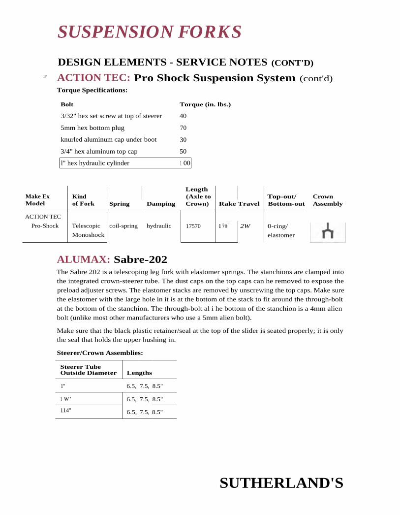
CrownAssembly
SUSPENSION FORKS
DESIGN ELEMENTS - SERVICE NOTES (CONT'D)Tr
ACTION TEC: Pro Shock Suspension System (cont'd)Torque Specifications:
Bolt Torque (in. lbs.)
3/32" hex set screw at top of steerer 40
5mm hex bottom plug 70
knurled aluminum cap under boot 30
3/4" hex aluminum top cap 50
l" hex hydraulic cylinder 1 00
LengthMake Ex Kind (Axle to Top-out/Model of Fork Spring Damping Crown) Rake Travel Bottom-out
ACTION TEC
Pro-Shock Telescopic
Monoshock
coil-spring hydraulic 17570 1 5/8" 2W 0-ring/
elastomer
ALUMAX: Sabre-202The Sabre 202 is a telescoping leg fork with elastomer springs. The stanchions are clamped into
the integrated crown-steerer tube. The dust caps on the top caps can he removed to expose the
preload adjuster screws. The elastomer stacks are removed by unscrewing the top caps. Make surethe elastomer with the large hole in it is at the bottom of the stack to fit around the through-bolt
at the bottom of the stanchion. The through-bolt al i he bottom of the stanchion is a 4mm alien
bolt (unlike most other manufacturers who use a 5mm alien bolt).
Make sure that the black plastic retainer/seal at the top of the slider is seated properly; it is onlythe seal that holds the upper hushing in.
Steerer/Crown Assemblies:
Steerer TubeOutside Diameter Lengths
1" 6.5, 7.5, 8.5"
1 W' 6.5,
6.5,
7.5,
7.5,
8.5"
114" 8.5"
SUTHERLAND'S

brake studs 90-110
90-110crown pinch bolts
Spring Damping
Length(Axle toCrown) Rake Travel
Top-out/ I Crown
Bottom-out Assembly
elastomer elastomer 1 61/8" 1 1/2" 1 A" bumper/
bumper II
Bolt Torque (in. lbs.
brace bolts 60-80
thru bolts 60-80
Make 6r KindModel of Fork
ALUMAX
Sabre 202 Telescopic
Elastomer Color
black
green
red
SUSPENSION FORKS
DESIGN ELEMENTS - SERVICE NOTES (CONT'D)
ALUMAX: Sabre-202 (cont'd)Elastomers:
Density
soft
medium
hard
Torque Specifications:
AMP RESEARCH: F-1 and DownhillBoth the standard and the downhill forks have linkage designs with the linkage at the crown.
The downhill fork is similar to the standard fork except it has dual through-shaft damping units
with different valving instead of the standard's single damping unit. There is a retrofit kit avail-
able from the manufacturer to upgrade a standard fork to a downhill.
Spring preload is adjustable with a flathead screwdriver and 13mrn wrench. Spring preload
should he set so that the damping unit is extended 5mm with the rider on the bike. 'fire clear-
ance should be at least 1 lmm from the tire to the bottom of the fork crown.
Coil Springs:
Stiffness J Rating (spring constant)
soft
medium
hard
900 lbs./in.
1060 lbs./in. (standard)
1150 lbs./in.
SUTHERLAND'S

Steerer TubeOutside Diameter Lengths (millimeters)
1" 130, 165, 200, 235, 260 unthreaded
SUSPENSION FORKS
DESIGN ELEMENTS - SERVICE NOTES (CONT'D)
AMP RESEARCH: F-1 and Downhill (cont'd)The damping units are serviceable. Use 7.5 wt. transmission fluid for oil. Take care when clamp-ing the shock units; use AMP shock clamp tool #760. When overhauling the shock, make surethere is no air left in the system. If replacing the seals, soak them in oil before installing them.1)o not use solvent to clean the shock and do not over-tighten the shock end cap (use light pres-
sure - slightly more than finger tight).
Due to the design of the crown for the linkage, the crown may hit the down tube of certainbikes. if this happens, place spacers between the crown and the headset crown race to increase
the crown-down tube clearance. AMP has both 1.5 and 3mm frame clearance spacers (any thick-er and the headset crown race may not fit properly). This will also proportionally increase theaxle- to-crown length – affecting the head tube angle slightly.
Replacement crown/steerer assemblies are available but require external snap ring pliers and
AMP's pin press to change the legs.
Steerer/Crown Assemblies:
1 W 130, 165, 200, 235, 260 unthreaded
Make 67 KindModel of Fork Spring Damping
Length(Axle toCrown) Rake Travel
Top-out/Bottom-out
CrownAssembly
AMP
RESEARCH
F-1
Linkage coil-spring hydraulic 16.75"no load/16.5"
static load
1 1/2' 2" none/
elastomer
steerer/
crown unit
legsseparate
Down Hill Linkage coil-spring hydraulic same as
above
1 1/2" 2" none/elastomer
same asabove
ANSWER: Manitou 1, 2, 3, 4, Sport, Magnum, EFCThe Manitou 1, 2, 3 & 4. NI-Sport, Sport, Magnum, and FTC, are a telescoping leg, elastomerspring design. The stanchions on all Manitou forks (and Sport forks) arc the same diameter andcan use the same crown. The brake arches of the Sport (`94), Manitou 2, and Manitou 3 are inter-
changeable; the brake arches of the original Man itou and the M-Sport are not interchangeable.
Manitou: The original Man itou is a telescoping leg fork with elastomer springs and top-outbumpers but no bottom-out bumpers. Its steerer tube, crown, and stanchions are completely sep-arate, although these can he replaced with the newer one piece crown and steerer combinations.
SUTHERLAND'S

SUSPENSION FORKS
DESIGN ELEMENTS - SERVICE NOTES (cowl))ANSWER: Manitou (cont'd)Some of the newer crowns are very lightweight and can be damaged it the stanchions spread
them too much. To prevent damage to the crown when installing the stanchions onto
the crown, have the crown pinch bolts lightly threaded into the holes. Minimum tire
clearance is 1 3/4" (45mml. Level the top of the stanchions with the top 01 the crown — do not
raise or lower the stanchions.
To reach the elastomers, remove the lower leg fixing bolts from the top of the stanchions and
remove the sliders. Remove the dust seals and upper and lower bushings from the sliders. Forreassembly, first load everything on the lower leg retaining bolts so you do not have to find the
holes in the washers while they are in the slider. Insert the upper bushings and seals. The upper
dust seal is very difficult to replace. The upper seals should he fully seated in their grooves beforethe stanchions are inserted. Run your finger around the seals to feel that they are properly seated.
Then place the lower leg fixing bolts (with top-out bumpers) in the stanchions. In the followingorder, place on the fixing bolts: the lower bushing, the compression washer, the smaller elas-tomer, another compression washer, and the larger elastomer. To fit the lower hushing in the slid-er, squeeze it past the upper hushing. Did it pop hack into shape properly? Attach and torque the
lower leg fixing bolts to specifications. Slowly thread the lower leg fixing bolts; it may take them alittle while to fit into the threads at the bottom of the sliders properly. Do not fully tighten one
leg and then insert the other bolt — get both holts started at the same time and then tighten them.
General MaintenanceRoth the upper dust seal bushings and the fork brace alien screws wear and will need to he
replaced. Do not screw the compression stack bolt too tightly as the bolt may punch through the
al urn i num drop-out assembly.
M-Sport ('93): The original Manitou elements apply here except the M-Sport has a one piece
steerer tube/crown and it has 3 3/4" stack of three elastomers separated by compression washers.
Minimum tire clearance is: 1 3/4" (45mm).
Manitou 2: Most original Manitou elements apply here, also. But like the elastomer stack on theM-Sport, the Manitou 2 stack is longer. Adjust the elastomer preload on the Manitou 2 by turn-
ing the plastic knobs at the bottom of the legs. When installing the sliders onto the crown,thread the crown pinch bolts lightly into the holes to prevent damage to the crown. Also, align
the vent holes in the stanchions with the crown slots. Minimum tire clearance is : 1 3/4" (4Smm).
Sport (`94): This model has a one piece steerer tube and crown and a 3 3/4" stack of three elas-
tomers which are separated by cup washers and accessed like the Manitou. The Sport is different
as a retaining ring holds the upper hushing and dust seal in place. Pull up the dust seal cover to
expose the retaining ring and use a screwdriver to pry the ring off so the sliders can be removed.
Do not damage the upper seals or stanchions; you may need to use some force pulling the stan-
chions out of the sliders to remove the upper seals.
To re-assemble the fork, align the upper dust seal covers, the retaining rings, the upper dust seals,and the upper bushings over the stanchions. Insert the lower bushings on the stanchions, stack
SUTHERLAND'S

SUSPENSION FORKS
DESIGN ELEMENTS - SERVICE NOTES (coNro)
ANSWER: Manitou (cont'd)the elastomers on the lower leg fixing bolts, insert the bolts through the stanchions, and inserteverything in the lower leg. Press the upper bushing and dust seal into place with a screwdriveror similar tool, and install the retaining ring, seating it correctly. Finally, thread and tighten thelower leg fixing bolts.
Minimum tire clearance is 2 1/8" (54mm).
Manitou 3: To adjust the elastomer preload, turn the black knobs on the top of the stanchions.To replace the elastomers, unscrew the blue knob at the top of the stanchion. This model hastop-out and bottom-out bumpers. A retaining ring, si milar to the one on the Sport ('94), holdsthe upper hushing and dust seal.
Disassembly of the fork is a four-step procedure: 1) unscrew the compression rod screws at thebottom of the sliders while compressing the fork to keep the compression rods from turningwith the screws, 2) remove the upper seal retaining ring as with the Sport ('94), 3) remove thepositive bottom clips and bottom-out elastomers from the compression rods, and 4) remove thecompression rods.
To convert to a long travel setup, remove a 1/2" top-out elastomer from each compression rod. Eachrod should now only have one 1/2" top-out elastomer. Finally, add a 1/2" elastomer to each stack.
Re-assembly is a five-step procedure: 11 place the compression stack with top-out bumpers hack
in the stanchions, 2) install the bottom-out bumpers and positive bottom clips (in that order), 3)install the stanchions and bushings as with the Sport ('94), 4 .) install the elastomer stacks intothe stanchions, and 5) install the compression rod screws on the bottom of the sliders. To keepthe compression rods from turning with the screws, compress the suspension. Minimum tire
clearance is 21/8" (54mm) in the standard configuration or 2W (67mm) for the long travel setup.
Manitou 4 ('95): Manitou 4 is similar to Manitou 3 in that it has removable elastomer stacksthat are unscrewed from the top of the stanchions. The preload can be adjusted by hand using
the indexing knobs at the top of the stanchions. Each skewer has a stack of six 1" elastomerswhich are separated with plastic cup washers.
Disassemble and re-assemble the fork as you would the Manitou 3; note that Manitou 4 has onlyone top-out elastomer. When re-assembling, put the positive bottom clip on the correctlylabeled slot in the compression rod. if you put the positive bottom clip in the ER: slot or do notinstall the clip, the fork may compress enough for the tire to strike the crown. The positive bot-
tom clip in the Magnum slot (labeled "MAG") will reduce the forks travel.
The newer 1995 model forks, a crown/steerer tube combination with a split crown, have a single
bolt pinch clamp for each stanchion. Insert the stanchions completely as these crown/steerertube combinations have a inside lip. If there is no lip, level the top of the stanchion with the topof the hole in the crown.
Minimum tire clearance is 2 3/8" (60.3mm).
SUTHERLAND'S

Density Elastomer Color
extra soft
soft
medium
black
blue
red
hard ellow
extra hard brown
medium (cold weather) green
SUSPENSION FORKS
DESIGN ELEMENTS - SERVICE NOTES (CONT'D)
ANSWER: Manitou (cont'd)Magnum ('95): The Magnum, Like the Manitou 3, has a top loading skewer with adjustable pre-
load. Unlike the Manitou 3, the preload adjusts by removing the top cap and skewer, and clip-
ping the E-clip into position on the skewer holder (higher up for more preload). Because the pre-load adjustment is done with the skewer out of the fork, you may need to press down on the top
cap and skewer when screwing them into the fork. Be careful not to cross thread or strip out the
top cap or stanchion.
Minimum tire clearance is 2 1/8" (54mm).
Manitou EFC and Manitou EFC/DH ('95): The EFC and EFC/DH are elastomer spring forks
with oil damping. 'Elie EFC/DH has a special drop-out and uses its own hub and axle (included)
for torsional strength, otherwise the forks are the same. The elastomers are accessed from the top
of the stanchions. Preload is adjusted with the indexed knobs also at the top of the stanchions.
Damping is also adjustable.
Both EFC models have top loading skewers with knob adjustable preload. The stack of seven24mm elastomers are separated by plastic cup washers. The main compression elastomers usedby the EFC forks are not the same as those used by the other Manitou forks - the EFC elastomers
have oil damping, so they do not need elastomers with damping built into them.
The damping is integrated into the left stanchion. The knob at the bottom of the left slider
adjusts the rebound damping.
Minimum tire clearance is 31/2" (79.4mm).
5teerer/Crown Assemblies:
5teerer TubeOutside Diameter Lengths
1" 140(5.5"), 165(6.5"), 190(7.5"), 215mm(8.5"), 305mm(12") unthreaded
1 W 140, 165, 190, 215mm, 12" unthreaded
1 1/4" 140, 165, 190, 215mm, 12" unthreaded
Elastomers:
SUTHERLAND'S

SUSPENSION FORKS
DESIGN ELEMENTS - SERVICE NOTES (CONT'D)ANSWER: Manitou (cont'd)
Torque Specifications:
Model
CrownBolts(inch/lbs.)
Brake BraceBolts(inch/lbs.)
CantileverStuds(inch/lbs.)
Lower LegFixing Bolts(inch/lbs.)
Manitou 312 144 144 30
M-Sport 90-110 90-110 90-110 30-40
Manitou 2 90-110 60-80 90-110 30-40
Manitou 3 50-70 90-110 90-110 10-30 for the com-pression stack screws
Sport ('94) 50-70 90-110 90-110 30-40
Manitou 4, EFC,EFC-DH
(split crown)110-130
90-110 90-110 1 0-30
Make ELModel
Kindof Fork Spring Damping
Length(Axle toCrown) Rake Travel
Top-out/Bottom-out
CrownAssembly
ANSWER
Sport '94 Telescopic elastomer elastomer 16" 1 1/2" 1 W elastomer/
none I I
M-Sport Telescopic elastomer elastomer 16" 1 1/2" 1 1/4" elastomer/
none I I
Manitou Telescopic elastomer elastomer 16" 1 1/2” 13/4" elastomer/
none
Manitou 2 Telescopic elastomer elastomer 1 6" 1 1/2" 1 3/4" elastomer/
none I I
Manitou 3 Telescopic elastomer elastomer 1 61/4" 1/2" elastomer/
none I I
Manitou 3
(long travel
conversion)
Telescopic elastomer elastomer 16W Ph" 21/2" elastomer/
elastomer IIManitou 4 Telescopic elastomer elastomer 16W 1 1/2" 2 A" elastomer/
elastomer I I
Magnum Telescopic elastomer elastomer 161/4" 1 1/2" elastomer/
elastomer IIManitou Telescopic elastomer hydraulic 17" - 1 1/2"
11 elastomer/
EFC cartridge elastomer 1
SUTHERLAND'SS

SUSPENSION FORKS
DESIGN ELEMENTS — SERVICE NOTES (CONT'D)
ANTI GRAVITY: Stage 1-4The Anti Gravity Stage 1 – 3 arc telescoping leg forks with elastomer springs, top-out bumpers,no bottom-out, and no separate damping. As with most elastomer forks, remove both sliders at
the same time and do not remove the fork brace unless necessary.
Be careful when exchanging elastomers: there are no bottom-out bumpers in these forks. Thebottom-out is designed-in with the maximum compression of the elastomers. Use the samelength (stack height) of elastomers and be certain to use either Anti Gravity or compatible elas-
tomers. The fully compressed stack length of the elastomer stack should not be less than 2".
Normal stack length (4") minus the travel (2") equals fully compressed stack length (2").
Stage 1 and Stage 2: Both forks, like the Tange Shockblade, have separate crown, steerer, and
legs. Access the elastomers by removing the lower leg fixing bolts, removing the sliders, andremoving the upper bushings from the slider. The Stage 1 upper bushing is held in by the upper
seal, while the Stage 2 upper bushing is threaded in. The elastomers will just slide out of the slid-ers along with the lower bushing. When re-assembling, make sure the lower hushing goes on topof the elastomer stack with the open end up. Properly seating the seal on the Stage 1 is crucial(see Tange Struts, pages 15-48 thru 15-49). (he bushings on the Stage 2 are protected bythe boots, so scat the boots and retaining 0-rings properly around the sliders before riding.
Stage 3 Pro: This fork has legs pressed into the crown. The steerer tube is clamped on and the 1",
1-1/8", or 1-1 W steerer tubes with the same crown can be adapted for smaller diameters. When
using the special crown adapters, line up the split in the adapter with the split in the crown and
properly engage the groove in the steerer tube with the lip on the adapter. The bushings on theStage 3 are protected by the boots, so properly zip-tie the hoots to the sliders before riding.
Stage 4: The Stage 4 is available in 7 different models: Stage 4, 24" (for 24" wheels); Stage 4, 26";Stage 4 Pro 26"; Stage 4 Pro Comp 26"; Stage 4 Carbon 26"; Stage 4 Pro Carbon 26"; and Stage 4
Pro Comp Carbon 26". The Carbon models have carbon fiber sliders instead of aluminum. Promodels have the 6 inch elastomer upper stack, whereas, Pro Comp models have the 6 inch upper
elastomer stack with a preload adjuster. As with the Stage 3 Pro, the crown fits any size steerertube with the use of shims. Crown race adapters are used to fit the headset crown race snugly
onto the steerer tube.
The basic design is the same as the Stage 3 Pro: telescoping legs, elastomer sprung, no damping,
and 2" of travel. Stage 4 models without the 6 inch elastomer upper stack can be converted to
2.5" of travel.
6 inch elastomer upgrade: This retrofits Stage 3 and 4 for an additional 6 inch elastomer
stack that drops in at the top of the crown. The elastomer stack is an addition to the existing
elastomers, not a replacement - removing the lower elastomer stack may cause the tire to
strike the crown. Instead, the original elastomer stack should be replaced with softer elas-tomers. Adjust fork stiffness by replacing the upper (retrofit) elastomers. Note: the upper elas-
tomers are different than the lower elastomers.
SUTHERLAND'S

Density Elastomer Color
soft black
medium orange
hard purple or blue
Crown Bolts(inch/lbs.)
Lower Leg Fixing Bolts(inch/lbs.)Model
Stage 2 25-30
Stage 3 10-15
3
SUSPENSION FORKS
DESIGN ELEMENTS - SERVICE NOTES (CONT'D)
ANTI GRAVITY: Stage 1-4 (cont'd)External index adjustment kit: This is used in conjunction with the 6 inch elastomer upper stack
to provide preload on the upper elastomer stack. Adjust the preload with a 6mm alien wrench.
Steerer Assemblies:
Steerer TubeOutside Diameter Lengths (millimeters)
1" with shim 130, 160, 190, 220, 250, 280, 250 unthreaded
1 1/a" with shim 130, 160, 190, 220,
220,
250,
250,
280, 250 unthreaded
1 1/4" 130, 160, 190, 280, 250 unthreaded
Elastomers:
Torque Specifications:
(LengthMake Ea Kind (Axle to Top-out/ CrownModel of Fork Spring Damping Crown) Rake Travel Bottom-out Assembly
ANTI GRAVITYStage 3 Pro Telescopic microcellular elastomer
urethane16 1/2' 1 1/2" 2" elastomer/
none
I
riStage 4 Telescopic microcelluiar elastomer 1 61/2"
urethane
11/2" 2" elastomer/
none
I
ri
AVITAR: (See Shower)
SUTHERLAND'S

SUSPENSION FORKS
DESIGN ELEMENTS - SERVICE NOTES (CONT'D)
CANNONDALE: Delta V, Headshok DD,Headshok RDC, Headshok ELSThe Cannondale Headshok forks are monoshock telescoping forks with the slider and stanchion
inside the head tube. The fork uses a non-standard size head tube, headset, and stem, so it is onlyavailable on the Cannondale Delta V and Super V series of bikes and framesets. As with the ActionTec fork, the boot at the crown of the fork is the only thing that protects the bearing surfacesfrom contamination. It uses adjustable needle bearings on the sliding surfaces for low friction.
The fork must be removed from the frame in order to grease the needle bearings or to adjust
them or to change the shock cartridges. The needle bearings rarely need to be adjusted.
To remove the fork, take off the adjusting cap and stem. Loosen the lower bearing retaining
screw. Using a section of pipe (such as a cut section of steerer tube) to protect the valve oradjuster, if there is one, support the frame and tap on the top of the fork until it comes out thebottom of the head tube. Be careful to hold onto the fork so it does not drop to the floor.
Delta V 1992 & 1993: This fork was not marketed as a Headshok fork; it was more commonly
known as the Delta V fork. One version of the fork consisted of an air sprung, oil damped unit. It
had a Schraeder valve at the top of the steerer tube for pressure adjustment, and a rubber knobthat turned the Schraeder valve at the top of the steerer tube for damping adjustment. Air pres-
sure should he set so that there is just a bit of sag with the rider on t he bike; this would usually
be between 80 and 120 psi.
To inflate the fork, sometimes it is necessary to remove the adjuster and damping dial to be able to
thread on a Schraeder pump. The damping dial is a hexagonal piece of aluminum held onto the
valve body with a set screw. When re-installing the damping dial, seat it in the same position on
the valve body. If it is too low, the rider may not be able to adjust the fork for enough damping.
The fork can be retrofitted to a 1994 cartridge-style air/oil or elastomer unit with special tools.
Instructions are provided with the retrofit cartridge unit. The elastomer retrofit cartridge is avail-
able with either a hard or soft elastomer.
Maintenance Recommended By Cannondale for Delta V:Every three months: Grease the flats of t he bearing surface. To do this, remove the upper zip-
tie holding on the boot, and peel the boot down. This will allow you to grease the flats. Re-
secure the boot in the groove properly; the groove will sit in the flange. Secure the boot with a
zip-tie. Depressurize the fork, remove the Schraeder valve core with a core remover, and drip a
few drops of light oil into the air chamber.
Once a year: Lubricate the needle bearings by removing the fork and using a grease gun to
inject grease in the four grease ports in the center of the fork. Make sure you get grease in the
grease ports and not in the needle bearing adjuster holes. Cannondale recommends about two
squirts of synthetic grease per port.
SUTHERLAND'S

Make ElModel
Kindof Fork
Length(Axle to
Spring Damping Crown) RakeTop-out/
Travel Bottom-out
CANNONDALE
Delta V Telescopic
monoshock
air oil I 7 7/8" 1 3/4" varies bumper/
bumper
Headshok DO,
Headshok RDC
Telescopic
monoshock
air oil 17 7/8
" 1 3/4 varies bumper/
bumper
Headshok ELS Telescopic elastomer
monoshock
oil 1 7 7/6" 13/4" varies bumper/
bumper
CrownAssembly
111Custom
Custom
IiiCustom
t
SUSPENSION FORKS
1 I I DESIGN ELEMENTS - SERVICE NOTES (coNTD)CANNONDALE: (coned)Headshok OD, Headshok RDC, Headshok ELS 1994: There were both air sprung (Headshok
DD and licadshok RDC) and elastomer sprung (I leadstiok HS) forks for 1994 model bicycles.
The inflation valve for the air sprung fork is now on the underside of the steerer tube. The fork
should always be ridden, stored, and transported (even on airplanes) with at least 75
psi. of pressure. 1lie air pressure should generally be 3/4 the rider's weight, or more specifically,
the air pressure should he set so that there is 1/16' sag with the rider on the bike.
The 1994 air sprung fork comes in two versions, one with an adjuster knob at the top of the
steerer tube (called the Headshok DD) and another (called the Headshok RDC) with the adjuster
coupled to a thumb shifter on the handlebar. The damping for both forks is the same, from full
lockout to minimal damping. If you need to re-adjust the indexing on the damping, zero the
damping in the full lockout position. Turn the adjuster knob completely clockwise, to the locked
out position, or push the thumb lever all the way forward. Remove the adjuster cap or cap plate.
Loosen the pinch bolt holding the split nut or collar to the center shaft. Use a screwdriver to
turn the center adjuster until the fork just begins to lock out completely. Stand the bike on the
ground and press down on the handlebars while slowly turning the adjuster shaft until the fork
is firmest. Tighten the pinch bolt and test the lockout again. Re-install the top cap or plate.
Note: The 1994 Headshok RDC (with the Remote Damping Control lever mounted on the han-
dlebar) was susceptible to failure of the remote damper. Replace the RDC lever with the DD knob.
The 1994 elastomer fork, I leadshok ELS, has elastomer preload adjusted by the alien set screw at
the top of the steerer tube. To get to the adjuster, unscrew the black top cap.
CONCEPT: (See AMP)
SUTHERLAND'S

SUSPENSION FORKS
DESIGN ELEMENTS - SERVICE NOTES (CONT'D)
CONTROL TECH: Lawwill LeaderThe Lawwill Leader has a parallelogram-style linkage design near the wheel axle and an air/oil
monoshock bolted on in front of the head tube. The height of the legs on the crown is
adjustable and this capability slightly' modifies the compression characteristics of the fork.
The monoshock is an air/oil design. Both the air and the oil pressure in the shock can be adjust-
ed. Older models were air pressurized with a needle valve, whereas newer ones have a Schraeder
attachment. The air pressure range should be between 55-95 psi. For the oil pressure, both the oil
level and oil weight are adjustable. To change the oil in the newer models, first depressurize the
shock. Be careful while doing so, because the oil may be emulsified and spray out. Then, remove
the Schraeder valve core and pour the oil out. The fork is built with 551n1 of lOwt oil, so when
replacing the oil, use more than 50m1 and less than 60m1.
The steerer tube is pressed into the crown, and the legs and shock unit are clamped onto the
crown. Unlike most forks, the legs are clamped behind the steerer tube. This is the only' way to
clamp on the legs and still be able to clamp on the monoshock unit. The suspension
action/articulation can be controlled somewhat by where the crown clamps onto the legs.
The pivot points on both older and newer forks have eight grease ports that use a needle-style
grease gun. The pivots should be greased sparingly, but often.
Steerer/Crown Assemblies:
Steerer TubeOutside Diameter Lengths
1" 12" threadless
1 1/s" 2" threadless
1 1/4" L12" threadless
Kindof Fork Spring Damping
Length(Axle toCrown) Rake
Top-out/ CrownTravel Bottom-out Assembly
Linkage air hydraulic 17" 1 1/4"
steered
crown unit2.5" O-ring/O-ring legs separate
Make &Model
CONTROL
TECH
Lawwill Leader
DIRT RESEARCH: Al-Carbon Fiber, Aluminum,Ti-Carbon FiberThe Dirt Research forks are all standard telescopic leg forks with elastomer springs. The stack of
four 4cm-long elastoniers are loaded through the top of the legs and are held onto the skewer
with 0-rings. The preload is adjustable using a 6mm alien wrench at the top of the legs.
SUTHERLAND'S

SUSPENSION FORKS
DESIGN ELEMENTS - SERVICE NOTES (CONT'D)
DIRT RESEARCH: (cont'd)The crown, steerer, and legs are all separate, but the steerer has the crown race seat bonded ontoit. So, in order to remove the steerer tube, remove the snap ring at the bottom of the crown.
The elastomers push against through-shafts that have 6mm alien heads in them and are held inplace with a 5mm bolt at the base of the slider. Use a long 6mm alien wrench to hold the through-shafts in place and use a 5mm alien wrench (or a long 5min alien wrench for the aluminummodel) to remove the bolt at the base of the slider. The white plastic upper bushing retainers arethreaded into the slider. After those are removed, the sliders and stanchions can be separated.
Torque values, steerer tube sizes, and elastomers are unavailable.
Make flzModel
Kindof Fork Spring Damping
Length(Axle toCrown) Rake Travel
Top-out/Bottom-out
CrownAssembly
DIRT
RESEARCH
Aluminum Telescopic elastomer elastomer 165/8" 1 1/2" 1 1/2" elastomer/
elastomerII
Aluminum/
Carbon FiberTelescopic ,Iastomer elastomer 1 6-1/4" 1 1/2" 11/2" elastomer/
elastomer I II
GIRVIN: VectorThe Vector is a monoshock linkage suspension fork with the linkage at the crown and stem. Thespring is elastomer and damping is provided by a urethane-friction unit. When the fork gets overdamped, the damping unit must he disassembled and lightly greased. Refer to service manual forgreasing instructions.
The suspension fork is clamped to its own threadless stem (available in 120, 135, and 150mmlengths). Install a special headset sizing spacer onto the headset for 1 1/4" and 1 1/4" forks. The stemposition is very important to the proper functioning of the fork, because the linkage is directlyattached to the stem. The top of the stem should sit 1.5 - 3mm higher than the top of the(uncut) steerer tube and the stem is not adjustable.
To modify ride characteristics of the forks, rotate the lower front eccentric pivot. There is a holein the middle of the eccentric pivot. When the chamfer in the hole is facing forward, the fork isin anti-pogo mode; when the chamfer is facing back, the fork is in the sensitive mode.
The elastomer preload is adjusted by tightening or loosening the blue I9mm nut (the preloadadjuster) at the bottom of the shock absorber. Set the preload so that there is 3 - 8n n of sag inthe sensitive mode or 0 - 3mm of sag in the anti-pogo mode.
To replace the elastomer, do not unscrew the bearing spring mount from the guide rod, or thesepieces will have to be replaced.
SUTHERLAND'S

extra soft 20
soft 30
medium 40
hard 50
extra hard 60
SUSPENSION FORKS
DESIGN ELEMENTS - SERVICE NOTES (CONT'D)
GIRVIN: Vector (cont'd)Check for wear or bending, especially at the guide rod, spring, or damper. Older models had alu-
minum upper pivot mounts that could bend under extreme use. Newer models have stronger
steel pivot mounts.
The lower link should not hit the stop plate on the legs. If it does, check that the stem is at the
proper height and that there are no loose parts. The shock absorber cannot have loose parts.
The steerer assemblies are replaceable, but this requires disassembly of the fork. Use the service
manual as a guide.
Steerer Assemblies:
Steerer TubeOutside Diameter Lengths
1" 1 33mm maximum head tube length
11/8" 127mm maximum head tube length
1/4" 127mm maximum head tube length
Elastomers: (the number is stamped on the end of the elastomers)
Density Elastomer Number
Torque Specifications:
Torque (in. lbs.)
stern pinch bolts
upper and lower link pinch bolts (4 total)
LengthMake is Kind (Axle to Top-out/ CrownModel of Fork Spring Damping Crown) Rake Travel Bottom-out Assembly
GIRVIN steerer/
Vector Linkage elastomer friction 161/2" 1 W 2+" urethane/none
crown unit
legs separate
SUTHERLAND'S
Bolt
100
1 00

Density Elastomer Color
soft white
medium yellow
medium/hard blue
hard red
SUSPENSION FORKS
DESIGN ELEMENTS - SERVICE NOTES (CONT'D)
HALSON: InversionThe Inversion fork is an inverted telescoping leg design with the stanchions on the bottom.
To remove the 7" skewered elastomer stacks, unscrew the knurled knob at the top of the legs.The upper elastomers are interchangeable and can he added to for preload. But the last two inch-es of the stack must be the narrow diameter, 2" long, red elastomers.
Set up the fork so that there is about 1/4" sag. Clearance between the tire and the bottom of thecrown should be at least 3/16" when the fork is bottomed-out (i.e. without the elastomer stack in).
liaison recommends only Tri-Flo lubricant on the skewers and boots, and only Bel-Ray water-proof grease on the bushings. This is to protect the fork, for it has no seals and depends on theboots for contamination protection. Always check that the hoots are still soft and pliable,undamaged, and uncut, or replace them immediately.
The crown, upper legs and steerer are a single unit and cannot he individually replaced.
Steerer/Crown Assemblies:
Steerer TubeOutside Diameter Lengths (millimeters)
1 40, 170, 200, 230, 260 unthreaded
1 1/4" 1 40, 170, 200, 230, 260 unthreaded
1 1/4" 140, 170, 200, 230, 260 unthreaded
Elastomers:
Torque Specifications:
Bolt Torque (in. lbs.)
brake brace bolts 120
LengthMake lx Kind (Axle to Top-out/ CrownModel of Fork Spring Damping Crown) Rake Travel Bottom-out Assembly
HALSON1
Inversion Telescopic elastomer elastomer 1 61/2" 1 1/2" 1 3/4 "bumper/bumper
SUTHERLAND'S

n
SUSPENSION FORKS
DESIGN ELEMENTS - SERVICE NOTES (coNT'D)
LAWWILL LEADER: (Sec Control Tech)
MARZOCCHI: XCAll Marzocchi XC series forks are air sprung, oil damped forks.
1 W and 11/4" crowns are available to fit XC50 through XC500 (older OEM bikes had 1" crowns).
Crown reduction rings are available in PA" to 1", 1 1/4" to 1", and 11/4" to 11/2" to fit the steerer
tubes to the crown.
1992 model forks: XC 100, XC 200, XC 300The XC 100 contains stanchion ported valving, in contrast to the XC 200 and 300 which con-
tain foot buffered valving in addition to the stanchion ported valving. All three forks are serviced
with special tools. Only the XC 300 has a separate "bush unit" (also known as the pilot boss)
that houses the upper hushing and seal assembly and needs to be removed with a pin spanner.
There are no rider-adjustable parameters besides air pressure. The forks come stocked with 7.5 wt
oil, which can be changed for different ride characteristics.
When disassembling these forks, remove the compensating piston and the air cap assembly
before pouring the oil out. Remove the air cap with snap ring pliers. Next, remove the compen-
sating piston by first removing the Phillips head screw and 0-ring from the middle of the piston.
Use a Marzocchi tool B (ref. 99) to keep the piston from rotating. Then, thread a 6mm threaded
rod or a long 6mm screw into the screw hole and pull the compensator piston out. A three-piece
basic tool kit is available for removing the air cap and compensating piston.
When re-installing the compensating piston, there should be no air trapped beneath it. Use
Marzocchi tool B (ref. 99) to insert the piston to its proper height (the oil level minus 5mm).
Another way to ensure there is no air beneath the piston is to put too much oil in, then press the
piston to the proper level (the intended oil height minus the thickness of the piston) letting the
excess oil escape through the hole in the piston. Then, put the Phillips head screw and 0-ring
hack in the compensating piston, and pour out the rest of the excess oil.
The main seals on the XC 300 are both held in with a snap ring and are fixed in a bush unit
threaded onto the top of the slider. This bush unit is unscrewed with a Marzocchi pin-style hookspanner tool (ref. 82). Remove the bush unit before servicing the upper bushings or seals.
Removing the bush unit also allows you to remove the stanchions.
1993 model forks: XC 50, XC 150, XC 400, XC 50HXC 50, XC 150: A press may be needed to create sufficient pressure to remove the seals. The most
efficient way to create this press is by removing the seal-retaining ring, adding oil, capping the
stanchion off again, and compressing it until the seal blows out. 1)o not damage the stanchion.
XC 400: There are no rider adjustable parameters on the XC 400, 150, and 50 besides air pres-
sure. the fork comes stocked with 7.5wt oil, which can be changed for different ride characteris-
tics. There is no static lockout on the XC 400, 150, or 50.
SUTHERLAND'S

SUSPENSION FORKS
DESIGN ELEMENTS - SERVICE NOTES (CONT'D)
it MARZOCCHI (cont'd)4 Note: These forks also have pistons that need to be removed before the oil can be poured out,(see comments about XC .1(X), 200, and 300 for removal and installation instructions).
XC SOH: This fork model is a version of the XC SO made for hybrids.
1994 model forks: XC 500, XC 51XC 500: These forks come with 20wt oil. Adjust the damping on the XC 500 by turning theknobs near the bottom of the legs: 1=minimum, 4=maximum damping.
Since these forks do not have compensating pistons, removing the stanchions and seals is prettystraightforward. If you cannot remove the stanchion from the slider, you may need to blow out the
seal as with the XC 150. The valving on the XC 500 is held at the bottom of the slider with a set
screw in the middle of the slider in the front. This may he behind the decal. Unscrew the set screwonly a couple of turns; this should allow you to lever the valve unit out. Disassemble the valve unitonly if necessary. When disassembling the valve, unit be careful because there is a spring loaded ballbearing in it. The 0-ring and conical seal on the valve unit need to be replaced after every, overhaul.When re-installing the valve unit, align the "1" on the valve with the mark on the slider. Put Loctiteon the set screw, tighten it lightly and hack it out 1/4 turn so the knob on the valve can be rotated.
XC 51: Like on the elastomer fork, the stanchion on the XC 51 is bolted in the slider at the bot-tom. Remove this bolt using a Marzocchi tool P ref. (5024) before removing the slider in order toaccess the seals.
1995 model forks: Zokes, Zokes LT, Zokes H, XC 600, XCRZokes, Zokes LT, Zokes H: These are telescoping leg, elastomer forks with adjustable preload atthe top of the crown.
XC 600, XCR: XC 600 and XCR are telescoping leg, air/oil forks with rider adjustable valving.Both use 20wt oil. The design and disassembly of the XC 600 resembles that of the XC 500,
although the valving is slightly different. The XCR resembles the XC 51 in that the stanchion isheld in with a compression rod bolted to the bottom of the slider. The XCR also has a knoballowing the compression damping to be adjusted.
The stanchions of the XC 600 and XCR, however, measure 26mm which varies from the 24mmmeasurement of the previous XC forks. The old crowns do not fit these new models. The newcrowns are a combination crown-steerer tube.
Steerer Assemblies (Note: XCR and XC 600 do not fit any other XC series forks):
Steerer TubeOutside Diameter Lengths (millimeters)
1" 129, 154, 180, 210, 230, 180 unthreaded, 220 unthreaded
PA" 129, 154, 180, 210, 230, 180 unthreaded, 230 unthreaded
1 W 129, 154, 180, 210, 230, 180 unthreaded, 230 unthreaded
SUTHERLAND'S

SUSPENSION FORKS
DESIGN ELEMENTS - SERVICE NOTES (CONT'D)
MARZOCCHI (cont'd)LJ
11
Elastomers:
Density Elastomer Color
soft yellow
medium blue
hard red
Recommended Oil/Air Heights (for various rider weights):
Model
Below 140 lbs. 140-180 lbs. Above 180 lbs.
Oil Air Oil Air Oil Air
MARZOCCHIXC 100+PH (7.5wt)* 55-60mm 40-80psi 50-55mm 40-80psi 45-50mm 40-80psi
XC 200 (7.5wt)* 55-60mm 40-80psi 50-55mm 40-80psi 45-50mm 40-80osi
XC 300 (7.5wt)* 55-60mm 40-80psi 50-55mm 40-80psi 45-50mm 40-80psi
XC 400 (7.5wt)* 45mm 40-80psi 40mm 40-80psi 35mm 40-80psi
XC 50 (7.5wt) 45mm 40-80psi 40mm 40-80psi 35mm 40-80psi
XC 150 (7.5wt)* 45mm 40-80psi 40mm 40-80psi 35mm 40-80psi
XC 500 (20wt) 50mm 40-80psi 45mm 40-80psi 40mm 40-80psi
XC 51 (20wt) 45mm 40-80psi 40mm 40-80psi 35mm 40-80psi
* Subtract 14mm when measuring to the top of co npensating piston.
1.* Important Note: Oil height is measured in millimeters from the top of the stanchion to the oil
surface when stanchion is fully compressed. Stock oil viscosity is listed with each manufactur-
er/model. Information in this chart supplied by Bicycle Technology International (BTI).
Torque Specifications:
Model
SteererPinch Bolts(ft. lbs.)
Brake Brace CantileverBolts Studs(in. lbs.) (ft. lbs.)
Foot Valve(ft. lbs.)
EGS, XC 50, XC 50H, XC 51, XCR 6 3.8 5.8 5.8
PF-1, XC 100, XC 200, XC 300, XC 400 6 3.8 5.8 4.5
XC 500, XC 600 6 3.8 5.8 n/a
Zokes, Zokes LT, Zokes H n/a n/a 5.8 n/a
Torques (from BTI):
Bolt
M4
Torque (in. lbs.)
70
M6 90
SUTHERLAND'S
M5 72

SUSPENSION FORKS
DESIGN ELEMENTS - SERVICE NOTES (CONT'D)
MARZOCCHI (cont'd)
Make EaModel
Kindof Fork Spring
Length(Axle to
Damping Crown) Rake TravelTop-out/Bottom-out
CrownAssembly
Marzocchi
EGS Telescopic air hydraulic 16W 1 W none/
noneI I
PF-1 Telescopic air hydraulic 1 6" 1 1/2" 1 W none/
none IIXC 100 Telescopic air hydraulic 161' 1 1/2 1 1/4" none/
none I II
XC 200 Telescopic air hydraulic 16" 1 /2" 1 1/4" none/
none IIXC 300 Telescopic air hydraulic 16" 1 1/2" 13/4" none/
none I IXC 400 Telescopic air hydraulic 16" 1 1/2" 13/4" none/
none IIrti
XC 50 Telescopic air hydraulic 16" 1 1/2" 1 W none/
none IIXC 500 Telescopic air hydraulic 16 3/s" 1 5/8" 1 1/4 " none/
none IIXC 50H Telescopic air hydraulic N/A N/A N/A none/
none I IXC 51 Telescopic air hydraulic 1 6W 1 W 21' none/
none IIXC 600 Telescopic air hydraulic 16 W 1 W 11 none/
none IIXCR Telescopic air hydraulic 163/8" 1 W
11 none/
none IIZokes Telescopic elastomer friction 16Y4" 1 W 11 spring/
none
Zokes LT Telescopic elastomer friction N/A N/A 2 1/2" spring/
none
Zokes H
(hybrid
Telescopic elastomer friction N/A N/A 1 W spring/
none
L 700C wheel)
SUTHERLAND'S

Elastomers:
Density Elastomer Color
yellow
natural
bluehard
soft
medium
SUSPENSION FORKS
DESIGN ELEMENTS - SERVICE NOTES (CONT'D)
McMAHON: ShakaThe Shaka is a telescoping leg, elastomer fork available with cantilever brake mounts or, by spe-
cial order, with U-brake/roller-cam brake mounts.
The stanchions and carbon fiber reinforced titanium steerers are bonded into the crown.
Steerer/Crown Assemblies:
Steerer TubeOutside Diameter Lengths (millimeters)
1" 160, 1 95mm, & unthreaded
1 W 160, 195mm, & unthreaded
When re-assembling the fork, the spring assembly stacks from bottom to top in this order: black
wear ring, aluminum washer, 21/4" elastomer, aluminum washer, and 21/4" elastomer. Do not seat
the black wear ring onto the plug in the bottom of the stanchion, otherwise the wear ring can-
not move past the upper wiper seal when it is seated on the plug; the ring must float freely just
below the stanchion plug. These forks arc designed for W to 1/2" sag. Additional springs can be
added for higher spring preload.
Torque Specifications:
Bolt Torque (in. lbs.)
fork crown bolts 1 30
LengthMake & Kind (Axle to Top-out/ CrownModel of Fork Spring Damping Crown) Rake Travel Bottom-out Assembly
McMAHON
Shaka Telescopic elastomer elastomer 16W 1 3/8" 2" elastomer/
noneII
MONGOOSE: Amplifier (See AMP Research)
SUTHERLAND'S

Steerer TubeOutside Diameter Lengths (millimeters)
154, 180, and 255 unthreaded
156, 175, and 255 unthreaded
1,
1 W
SUSPENSION FORKS
1 DESIGN ELEMENTS - SERVICE NOTES (coN-rD)
MONOLITH: ReboundRebound: now made on a special order basis only. Rebound H: discontinued.
MOUNTAIN CYCLE: SuspendersSuspenders, Suspenders II: both have been discontinued - we have no information on them.
PILOT: MK-2100SThe Pilot MK-2100S is a telescoping leg, elastomer fork with a top-out but no bottom-out bumper.
It has a one-piece steerer-crown-stanchion combination. Remove both legs to change the elas-
tomers. When removing the legs, as with other elastomer forks, it is not necessary to unbolt thefork brace. Loosen the lock bolt at the bottom of the sliders and unscrew the 5mm alien bolt
within the stanchions like other elastomer forks. Wait until you have removed the stanchions,then remove the snap rings at the top of the sliders. These snap rings hold in the bushings and
elastomers. Adjust elastomer preload by tightening the 5mm alien lower leg retaining bolt.
As with many elastomer forks without bottom-out bumpers, be very careful to replace the elas-tomers with the same kind or with ones provided by the manufacturer, in order to get the same
or less travel out of the fork. You do not want to get too much travel out of the fork because thetire may hit the crown, which could cause an accident.
Steerer/Crown Assemblies:
Torque Specifications:
1Bolt Torque (in. lbs.)
Fork brace 92
LengthMake 61 Kind (Axle to Top-out/ CrownModel of Fork Spring Damping Crown) Rake Travel Bottom-out Assembly
PILOT
MK-21005 Telescopic elastomer elastomer 16 3/4" 1 1/2" 1 1/2" bumper/none
SUTHERLAND'S
1 - I

SUSPENSION FORKS
DESIGN ELEMENTS - SERVICE NOTES (coNT/D)PROFORX: BMX, BMX Cruiser, Cross Country,Long Travel, ST (distributed under Girvin or Answer)11w ProForx suspension forks are a combination coil spring/elastomer, telescoping leg fork with elas-
tomer top-out bumpers. Two coil springs are available (hard or soft). The spring rates of the elastomersdo not need to be changed. Spring preload can be adjusted with a 7/16" (or llmm) socket wrench
and extension. Make sure the Nylock preload adjuster nut is properly engaged on the threads.
When disassembling the legs remove the fork brace. After you remove the fork brace, the springpreload nut, the upper dust seal cover, wiper, and seal retaining circlip, pound the slider off the
stanchion, because the upper seal is pressed in very tightly. Do not damage the thin upper lip of
the slider; use a wooden block placed against the brace mounting and pound on the wooden
block while supporting the stanchion. Keep the stanchion clamped into the crown. A Rock Shox
seal separator in conjunction with vise blocks will also work.
When re-assembling the fork, make sure the stepped spacer is engaged into the spring and the
elastomers are in the proper order (first blue, then red). Without the brake brace on, tighten orloosen the 7/16 preload nut until there is barely any play. Doing this assures that each leg is in
the same initial position. When adjusting the preload, make sure to turn the 7/16" nut the same
amount in each leg .
Minimum tire-to-crown clearance is 2" for the standard forks or 3" for the long travel forks. The
fork crown bolts for the crown with clamp-on legs and steerer tube should be tightened to 20 ft.
lb. of torque.
The manufacturer suggests removing, cleaning, and re-oiling the foam wipers underneath theblack nibber dust seals at the top of the sliders every eight hours of riding, or sooner for muddy
or sandy conditions. A complete disassembly and inspection should be done after every 200
hours of riding.
Although older steerer tubes are not sold by the manufacturer anymore, they are available else-where. They are sold by themselves, but sometimes need separate crown race seats. Newer steerer
tubes come with the crown.
Steerer Assemblies:
Steerer TubeOutside Diameter Lengths
1" 135,
5.5",
1 W 140,
1 1/4,, 140,
Torque Specifications:
Bolt Torque
175, 195, 215, 235mm, unthreaded (older- from Girvin)
7.5", 8.5", 12" threadless
200, 230mm, 260mm unthreaded (stock)
190, 215mm, 12" threadless (newer with crown)
in. lbs.)
155,
6.5",
170,
165,
crown bolts 20
SUTHERLAND'S

white 20mm
Density Elastomer Color Diameter
18.5mm
20mmfirm
solid
soft red
blue
I PI '1'11
SUSPENSION FORKS
DESIGN ELEMENTS - SERVICE NOTES (CONT'D)
PROFORX: (cont'd)
Make Ell
ModelKindof Fork Spring Damping
Length(Axle toCrown) Rake Travel
Top-out/ CrownBottom-out Assembly
PROFORX
BMX Telescopic elastomer!coil spring
friction 1 2 1/2" 11/2" 11/8" bumper/
none
III
BMXCruiser
Telescopic elastomer!coil spring
friction 1 41/2" 1'/2" 1 1/4" bumper/none I I
Cross
Country
Telescopic elastomer/coil spring
friction 1 6 1/8" 1 1/2" bumper/
none IILong
TravelTelescopic elastomer/
coil springfriction 17 3/8" 1 1" 111 bumper/
none IIST Telescopic elastomer/
coil spring
friction 1 6 1/8" 1 1/z" 2" bumper/
none III
ROCK SHOX: JudyThe Judy fork comes in three versions: X(.7,, DI i, and SL. The stanchions, sliders, and elastomer
stacks are the same on all three forks, but the crowns, brake braces, damping units and non-
damping shaft assembly often differ.
All the forks have adjustable and replaceable elastomer springs. To remove the elastomer stack,
the stanchion pinch bolts may need to be loosened. The elastomers can be changed or a solidspacer put in the place of one of the elastomers for a more progressive spring action. Adjust
spring preload by using the knobs at the top of the stanchions.
Elastomers:
Adjust the damping on DH and SL by inserting a 2mm alien wrench through the hollow bolt at
the bottom of the slider. There is only one damping unit, usually in the left leg. When re-assem-
bling the fork, the hollow bolt must he attached to the damping unit and not the non-damped
shaft assembly. The adjustable damping units have only two complete adjustment turns from a
fully tightened (clockwise) position. Do not turn the adjusting bolt past two turns counter-clock-
wise from a fully tightened position. You will run the risk of having the damping unit leak.
SUTHERLAND'S

SUSPENSION FORKS
DESIGN ELEMENTS - SERVICE NOTES (CONT'D)
ROCK SHOX: Judy (cont'd)The damping units are cartridge units and arc easily interchangeable and (along with the non-
damped shaft assemblies) are what affects the travel of the Forks. It is possible to change the travel
of the Judy fork by replacing the damping unit and non-damping shaft assembly. The only toolsneeded are an alien wrench for the shaft bolts at the bottom of the sliders and internal ring pliers.
Changing the damping units also changes the axle-to-crown distance. Though it is possible to dis-
assemble the damping units, without the proper tools it is difficult to re-assemble them properly.
To re-assemble the fork, first place the upper shaft guide with 0-ring and shaft end plate on the
unthreaded end of the non-damping through-shaft and, in this order, the top-out bumper andlower shaft guide on the unthreaded end. Insert the non-damping shaft assembly in the bottom
of the stanchion, unthreaded end first, press the lower shaft guide into the stanchion, and installthe snap ring into the groove in the stanchion. Set the upper shaft guide into the stanchion, and
install the snap ring into the groove in the stanchion. Set the upper shaft guide properly by
pushing the shall into the stanchion until the end of the shaft is flush with the end of the stan-
chion. Next put the shaft end plate on the unthreaded end of the damping cartridge and installthe unit in the bottom of the other stanchion, unthreaded end first; place the cartridge washerin the stanchion on the damping shaft and install the other snap ring. Thread the elastomerstacks into the stanchions, slide the stanchions into the sliders, and bolt the stanchions in at thebottoms of the sliders. Remember to use the hollow bolt on the damping unit side if necessary.
Regular maintenance includes lubing the stanchions, wipers, bushings, and elastomers with
clean Teflorin" based grease. Do not use lithium based greases.
The adjuster knobs on the crown may ride too high, causing it to strike the down tube of the
bike. The manufacturer recommends that you try adjusting the handlebar height so that the
handlebar hits the top tube before the adjuster knob hits the down tuhe.
Make fiModel
Kindof Fork Spring Damping
Length(Axle toCrown) Rake
Top-out/Travel Bottom-out
CrownAssembly
ROCK SHOX
Judy XC Telescopic elastomer hydraulic
cartridge
1 6 1/4" 1 W 2" bumper/
bumper IIJudy DH Telescopic elastomer
cartridge
hydraulic 1 7 1/4" 15/x' 3" bumper/
bumper IIJudy SL Telescopic elastomer
cartridge
hydraulic 161/4" 1 1/2" 2 1/f bumper/bumper
.1.II
SUTHERLAND'S

SUSPENSION FORKS
DESIGN ELEMENTS — SERVICE NOTES (CONT'D)
ROCK 51-10X: Mags QuadrasMag 10 '93, Mag 10 '94, Mag 10 Long Travel '94, Mag 20 '92, Mag 21 '93, Mag 21 '94,
Mag 21 51 (`93), Mag 21 51./Ti, Mag 21 Long Travel '93, Mag 21 Long Travel '94, May
21 7000, May 30 '92, Quadra '93, Quadra 10 '93, Quadra 21 '93, R5-1: The completeMag series of Rock Shox forks and the Quadra 21 can use the same style crown and steerer
combination, though they may differ in weight or rigidity. All the Mag and Quadra fork bracesare also interchangeable.
IdentificationThe RS-L, the original Rock Shox, was usually black with a triple clamp crown: both legs and
steerer clamped into the crown with bolts on the front face of crown. The RS-1 had some sealproblems, but improved seals are available.
RS-1, Mag 30, and Mag 10 '93 are the non-adjustable Mag shocks. All that can be easily varied on
these is the air pressure; of course, the oil can be changed with a little more effort. The Mag 30 isthe older shock (circa 1991 or 1992); the Mag 10 was made after 1992. The Mag 30 can be identi-
fied by the lack of the negative spring that Rock Shox incorporated in its later products. To checkfor the negative spring, grasp the crown and brake brace in both hands and try to compress the
fork with just your hands. If you are able to compress or extend the fork, it probably has the neg-
ative spring (or the air pressure is very low). It will probably be easier to extend the fork thancompress it, because of the static lockout.
Similarly, the Mag 20 (circa 1991 or 1992) had no negative spring either, but it had adjuster
knobs at the top of the stanchions for adjustable static lockout. The newer 1993 Mag 21 had the
negative spring and plastic adjusting knobs. The 1994 model has the negative spring and alu-minum adjuster knobs with sharp edges.
The 1994 Mag 10 had a negative spring like the 1993 Mag 10, but it also had an allen damping adjuster.
All models since 1994 should have stickers on the legs indicating the model.
Other indications of the vintage of the forks are the crown and brake brace. The older forks had
crowns with sharper edges, though since the crowns are interchangeable, an older fork may beequipped with the newer crowns with rounded edges. The brake brace on older forks had thebrake cable stop arm welded on, whereas the newer ones look cast. Some original M-20 braces
utilize countersunk mounting bolts. Rut all forks except RS-1 can use the new cast braces.
The 1993 Quadra has the grey legs, and alien caps at the tops of the stanchions for access to the
elastomers. The alien bolts are inside the alien holes for preload adjustments to the elastomers.
The 1993 Quadra's black crown has no bolts because both the legs and the steerer were pressed in.
The 1994 Quadra 10 is similar in appearance to the 1993 Quadra, but it has stickers on the legs
and generally a silver crown indicating the model.
The 1994 Quadra 21 has a bolt-on leg crown design and adjuster knobs on the stanchions.
SUTHERLAND'S

SUSPENSION FORKS
DESIGN ELEMENTS - SERVICE NOTES (CONT'D)
ROCK SHOX: Mags bt Quadras (cont'd)
GeneralOver torquing the fork brace bolts or the cantilever studs may strip the threads in the lower legs,
requiring that they either be replaced or have helicoil inserts installed.
The whole Mag series of shocks and the Quadra 21 can use the same crown and steerer tubecombinations, though the crown and steerer tube combinations may vary in weight and profile.
Do not overtighten the leg pinch bolts, as that may force the stanchions into oval shapes. Checkalso for cracking on the crown.
Mag and Quadra 21 Steerer/Crown Assemblies':
Steerer TubeOutside Diameter Lengths
1 1 40, 170, 200, 230, 260mm, 260mm unthreaded
1 1/2" 140, 170, 200, 230, 260mm, 260mm unthreaded
1 1/4" 140, 170 200 230, 260mm, 260mm unthreaded
Quadra 10 Steerer/Crown Assemblies':
Steerer TubeOutside Diameter Lengths
1 40, 170, 200, 230, 260mm, 260mm unthreaded
140, 170, 200, 230, 260mm, 260mm unthreaded
1 1/4" 140, 170, 200, 230, 260mm, 260mm unthreaded
Quadra Steerer/Crown Assemblies":
Steerer TubeOutside Diameter Lengths
1" 1 40, 170, 200, 230, 260mm, 260mm unthreaded
11/8" 140, 1 70, 200, 230, 260mm, 260mm unthreaded
1 1/4" 140, 170, 200, 230, 260mm, 260mm unthreaded
1 All three assemblies vary in design and are not interchangeable.
7
SUTHERLAND'S

Density Elastomer Color
redsoft
purple
green
ice blue
standard
hard
cold
SUSPENSION FORKS
DESIGN ELEMENTS - SERVICE NOTES (coNro)
ROCK SHOX: Mags bz Quadras (cont'd)R5-1 Steerer/Crown Assemblies:
Steerer TubeOutside Diameter Lengths
1" 1 40, 170, 200, 230, 260mm (Pre-'94)
1 I/8" 140,
140,
170,
170,
200, 230, 260mm (Pre-'94)
1 1/4" 200, 230, 260mm (Pre-194)*
* Rock Shox no longer stocks these three-piece units. However, the most recent one-piece steerer
and crown with separate legs is compatible.
Elastomers(Quadra):
Recommended Oil/Air Heights (for various rider weights):
Model
Below 140 lbs 140-180 lbs Above 180 lbs
Oil Air Oil Air Oil Air
ROCK SHOX
RS 1 (lOwt) 50-55mm , 35-40psi 45-50rnm 38-42psi 40-45mm 42-48psi
92 Mag 20 (8wt) 35-40mm 35-40psi 32-35mm 38-42psi 27-32mm 42-48psi
92 Mag 30 (8wt) 50-55mm 35-40psi 45-50mm 38-42psi 40-45mm 42-48psi
93 Mag 21 (8wt) 40-45mm 35-40psi 35-40mm 38-42psi 30-35mm 42-48psi
93 Mag 10 (8wt) 50-55mm 35-40psi 45-50mm 38-42psi 40-45mm 42-48psi
94 Mag 21, SL,
SL Ti (5w0 40-45mm 35-40psi 35-40mm 38-42psi 30-35mm 42-48psi
94 Mag 10 (5w1) 50-55mm 35-40psi 45-SOmm 38-42psi 40-45mm 42-48psi
93, 94 Mag 10
Long Travel (8wt) 45-50mm 38-42psi 40-45mm 40-45psi 35-40mm 42-psi
93, 94 Mag 21
Long Travel (8wt) 40-45mm 38-42psi 35-40mm 40-45psi 30-35mm 42-50psi
4 important Note: Oil height is measured in millimeters from the top of the stanchion to the oil sur-
face when stanchion is fully compressed. Stock oil viscosity is listed with each rnanufacturer/
model. Information in this chart supplied by Bicycle Technology International (B17).
SUTHERLAND'S

SUSPENSION FORKS
DESIGN ELEMENTS — SERVICE NOTES (CONT'D)
ROCK SHOX: Mags Quadras (cont'd)Torque Specifications:
Model Crown BoltsBrakeBrace Bolts
CantileverStuds
ValveAssembly
RS-1 27 ft. lbs. 7 ft. lbs. 9 ft. lbs. body: 35 ft. lbs.bolt: 5 ft. lbs.
Mag 10, 21 5 ft. lbs. 5 ft. lbs. 9 ft. lbs. body: 35 ft. lbs.
Quadra 10 n/a 5 ft. lbs. 9 ft. lbs. top cap: 5 ft. lbs
The Mag series of forks and the Quadra RS-1 are air sprung, oil damped telescoping leg forks.
Older models come with 8wt oil ('94's use Swt oil). The Quadra series (except the RS-1) are elas-
tomer sprung, friction damped telescoping leg forks.
Mag series: The Mag series of forks with the negative spring have coil spring top-out and elas-
tonier bottom-out bumpers. The other forks have bumpers for both bottom-out and top-out.
To remove the top caps with adjuster knobs, hold the adjuster knob steady or the circlip at thebottom of the stanchion may unclip or bend, or the adjuster rod may bend. Do not force the
adjuster knob to turn.
Disassembly of the forks is straightforward, but requires special tools. The eight steps to a smoothdisassembly are as follows: 1) release the air pressure, 2) remove the leg, 3) remove the top cap, 4)pour out the oil, 5) remove the upper dust seal cover and snap ring, 6) screw the seal remover(part #70113) together and put it over the stanchion, 7) clamp the stanchion in a vise with the
stanchion blocks (part #70101), and 8) separate the seal from the slider by unscrewing the sealremover. Unscrew the valve body with the valve body tool (part #70105) only when necessary.
When re-assembling an adjustable Mag fork, make sure you have the seals right side up. Replacethe air cap, hand tighten it and turn the adjuster knob counterclockwise until it stops. The num-
ber 1 should line up with either the arrow or the slot in the crown. Look for the arrow on the
top of the crown. if the number 1 does not align with either, rotate the stanchion until it does.
Mag 20: When adding oil, pump the stanchion slowly to keep from popping out the bottom
plate. This will distribute the oil evenly and get rid of the air bubbles.
Mag 21: When removing the top cap with adjuster knob, hold the adjuster knob steady or the
circlip at the bottom of the stanchion may unclip or bend, or the adjuster rod may bend. Do not
force it to turn.
Quadra series: Ali the Quadras have a top-out coil spring and bottom-out bumper.
l ubricate the elastomers well, especially at the ends so they do not twist when tightening the topcap or when preloading, or the elastomers may tear from the twisting. The boots are all that pro-tect the Quadra bushings from contamination so make sure the boots are well seated.
SUTHERLAND'S

SUSPENSION FORKS
DESIGN ELEMENTS - SERVICE NOTES (cowry)
ROCK SHOX: Mags bz Quadras (cont'd)Disassembly is a three-step procedure: 1) sliding the boots up, 2) removing the snap rings, and
3) pulling sharply on the sliders. If the sliders do not pull free, spray some light lubricant into
the sliders and heat with a hair dryer. Do not ignite the lubricant! Try again to separate the slid-
ers from the stanchions.
Make EaModel
Kindof Fork Spring Damping
Length(Axle toCrown) Rake
Top-out/Travel Bottom-out
CrownAssembly
ROCK SHOXMag 10'93 Telescopic air hydraulic 16" Std:11/2" 13/4" 0-ring/
Opt: 11/4" 0-ring 1 I
Mag 10 '94 Telescopic air adjustablehydraulic
16" Std:1 1/2"
Opt: 11/4"13/4" coil spring/
0-ring IIMag 10 '94 Telescopic air adjustable 16" Std:11/2" 21/4" coil spring/
Long Travel hydraulic Opt:11/4" 0-ring I IMag 20 '91,92
Telescopic air adjustablehydraulic
16" Std: 1 1/2"
Opt: 11/4"1 3/4" 0-ring/
0-ring IIMag 21 '93 Telescopic air adjustable
hydraulic16" Std: 1 1/2"
Opt: 11/4"
13/4" coil spring/0-ring II
Mag 21 '94 Telescopic air adjustablehydraulic
1 6" Std: 11/2"Opt: 11/4"
1 3/4" coil spring/0-ring 1 I
Mag 21 Telescopic air adjustable 16" Std: 1 '/2" 13/4" coil spring/SL '93 hydraulic Opt: 1 1/4" 0-ring I IMag 21 Telescopic air adjustable 16" Std: 1 1/2" 13/4" coil spring/SL/T1 hydraulic Opt: 1 1/4" 0-ring I IMag 21 '93Long Travel
Telescopic air adjustablehydraulic
161/2" Std: 11/2"Opt: 11/4"
21/4" coil spring/0-ring
-.LI I
Mag 21 '94 Telescopic air adjustable 161/2" Std: 1 '/2" 21/4" coif spring/Long Travel hydraulic Opt: 11/4" 0-ring IIMag 21 Telescopic air adjustable 15 5/x" Std: 1 1/2" coil spring/700C hydraulic Opt: 11/4" 0-ring IIMag 30 Telescopic air hydraulic 16" 5t& 11/2" 13/4" 0-ring/(-'91) Opt: 11/4" 0-ring I IQuadra Telescopic polymer-
springfriction 16" 1 1/2" 13/4" coil spring/
0-ring
SUTHERLAND'S

SUSPENSION FORKS
DESIGN ELEMENTS - SERVICE NOTES (CONT'D)
ROCK SHOX: Mags iSt Quadras (cont'd)
Make SrModel
Kindof Fork Spring Damping
Length(Axle toCrown) Rake Travel
Top-out/Bottom-out
CrownAssembly
ROCK SHOX
(cont'd)Quadra 10 Telescopic elastomer friction 16" 1 1/2" 1 1/4" coil spring/
0-ring
Quadra 21 Telescopic elastomer friction 16" 1 1/2" 1 3/4" coil spring/
0-ring IIRS-1 Telescopic air hydraulic 16" 0-ring/
0-ring II
RST: 200, 300, 380, 400, 460, 500, 600RST 380: The RST 380 is a telescoping leg fork with a combination of elastomers and coilsprings. Preload is adjustable at the tops of the stanchions with a 6mm allen wrench. Remove
the elastomer and coil spring stack by unscrewing the top cap by hand or with a 10mm alien
wrench. Then remove the springs and elastomers from their skewers by holding the brass cap on
the end of the skewer with pliers and unscrewing the preload adjuster with a 6mm allen wrench.Remove the sliders by unscrewing the shaft assemblies in the stanchions with a long 8mm alien
wrench. Minimum clearance is 52mm from the tire to the crown.
Elastomers:
Stiffness Elastomer Color 7soft yellow
firm blue
Torque Specifications:
Bolt Torque (In lbs.)
crown bolts 100-120
brake arch bolts 100-120
LengthMake Sr Kind (Axle to Top-out/ CrownModel of Fork Spring Damping Crown) Rake Travel Bottom-out Assembly
RST
380 Telescopic elastomer &coil spring
elastomer 161/4" 1 1/2" bumper/lone I I
SUTHERLAND'S

Elastomer Color
green
Density
soft
medium
firm
black
yellow
SUSPENSION FORKS
DESIGN ELEMENTS - SERVICE NOTES (CONT'D)
SCOTT USA: Unishock (Pre '93)Unishock, Unishock LF, Unishock LFR, Unishock 5, Unishock TX, Unishock VR:
The Scott Unishocks are a unicrown style, telescoping leg design. The steerer, crown, and stan-
chions are one piece. They all share the same basic design, but differ in materials and the type ofspring they use. All have spring preload, adjustable with a 4mm alien wrench through the hol-low bolts at the bottom of the sliders. The preload screw can be tightened down 1cm, which is
about 10 turns, from the fully loosened position. 'ate preload probably has a wider range, buttile manufacturer does not recommend it.
The coil spring forks, Unishock and Unishock 5, have 1/2" bottom-out and top-out bumpers.Elastomer spring forks have 1/4" bottom-out and 1/2" top-out bumpers.
The springs are accessed by removing the plunger bolts with Omm alien wrenches. This allowsyou to remove the sliders, remove the bottom-out bumper from the plunger, and then use apin spanner or a special Scott pin tool to remove the ringnut. The springs will then slide outthe stanchions.
The Unishocks TX, VR, LF, and LFR models may have either the VR elastomers (a stack of four
3cm-long elastomers with plastic separators between them on a skewer) or microcellular ure-thane (a single solid cylinder about 13cm long). Do not mix different VR elastomers.
Older models have a one-piece split bushing inside each slider. Newer models have two half-circle
bushings that should be matched. You can remove and clean the bushings and re-install them.
When removing them, keep them in a matched set: do not mix the sleeves from one leg withthe other. Do not clean the bushings with solvents. Install the sleeve bushings tapered end first.
All the coil spring forks are only friction damped. Therefore, the manufacturer warns not togrease the complete leg, just the sea] or boot area. The elastomers have some degree of dampingincorporated into them, so you can grease the complete stanchion on the elastomer forks or justthe seal or boot area for more friction damping. Also, grease the thread bolts on all the forks and
the elastomers. Do not apply any torque to the thread bolts as preload adjustments are made.The seals or stanchions should be cleaned and greased frequently: every 25 hours of use or less.
Minimum clearance for all models except the TX is 1.9" from the top of the tire to the bottom ofthe crown.
VR Elastomers:
SUTHERLAND'S

none
elastomer
elastomer
astomer
none
Damping
,istomer
CrownAssembly
SUSPENSION FORKS
DESIGN ELEMENTS - SERVICE NOTES (CONT'D)
SCOTT USA: Unishock (Pre '93) (cont'd)Torque Specifications:
Bolt Torque (in. lbs.)
hollow ringnut 8-10
lunger bolts 10
Make ixModel
Kindof Fork Spring
SCOTT
Unishock(pre '93)
Telescopic coil spring
Unishock LF Telescopic elastomer
Unishock LFR Telescopic elastomer
Unishock S Telescopic coil spring
Unishock VR Telescopic elastomer
Unishock TX Telescopic elastomer
Length(Axle toCrown) Rake Travel
Top-out/Bottom-out
161/4" .1/2" 1 3/a" bumper/bumper
1 61/4" 1 1/2" 1 3/a" bumper/bumper
1 6 1/4" 1'/2" 1 3/4" bumper/bumper
16'/4" 1 1/2" 1 3/4" bumper/bumper
16'/4" 1 1/2" 1 3/4" bumper/bumper
16 1/2' 1 1/2" 1" bumper/bumper
SHOCK WORKS: Motivator, Liberator, Enforcer,Enforcer FactoryTunefile Enforcer and the Liberator are telescoping lug, air/oil forks. The Enforcer has damping knobs
on top while the Liberator has preset damping. After removing the circlip under the upper seal,
remove the lower seal much in the same way as the seals are removed from the Rock Shox RS-1
or the Marzocchi XC-150: add oil to the shock, cap it off, and compress the fork, making the oil
pressure pop out the seal. Disassemble the rest of the stanchion much in the same way as the
upper seals are removed from the Rock Shox Mag 20: use the seal puller and the stanchion
clamps to extend the stanchion until the pressed-in upper hushing is removed. Remove the stop-
per at the bottom of the leg by applying compressed air to the hole at the axle seat. Be careful,
the stopper can go flying across the room. It can also he removed with a spoke, though that may
scratch the inside of the leg or tear the 0-ring on the stopper.
Be careful with the adjuster rod on the Enforcer as it is made of aluminum and may easily crack
or break. In addition, be especially careful when tightening the nut at the bottom of the
adjuster. Align the valve and valve plate properly so their grooves are aligned with each other
and the adjuster rod.
SUTHERLAND'S

SUSPENSION FORKS
DESIGN ELEMENTS - SERVICE NOTES (CONT'D)
SHOCK WORKS: (cont'd)Press the stanchion all the way down to force the stopper to the bottom of the leg when re-assembling the fork.
Torque Specifications not available.
Recommended Oil Volume:
ModelRecommended OilVolume
Enforcer 80cc
Liberator 83cc
Motivator 95cc
Make ElModel
Kindof Fork Spring Damping
Length(Axle toCrown) Rake Travel
Top-out/Bottom-out
CrownAssembly
SHOCKWORKS
Enforcer Telescopic air adjustable
hydraulic16 Ye N/A 1 3
/4" bumper/
bumper IILiberator Telescopic air adjustable
hydraulic16W N/A 1 3
/4" bumper/
bumper IIMotivator Telescopic ' air adjustable
hydraulic
1 6 3/8" N/A 1 3/4" bumper/
bumper II
SHOWA: EX-7The Showa EX-7 fork allows an adjustment range of 15mm air volume using the knob at the bot-
tom of the legs. This means there is no need to take the fork apart to change the oil level. Adjustthe air volume, and he sure to adjust the air pressure afterward. It is easier to make adjustmentsto the air volume if there is lower air pressure.
To change the oil, check that the adjusters at the bottom of the legs are in the same position.
Preferably, the adjusters should be at the uppermost position, because the fork needs to be pres-
surized to allow for proper downward motion of the air piston.
The manufacturer claims that the seals and surface of the stanchions are maintenance-free.
I - he seals are pressed in very tightly. To remove them, fill the stanchion with oil and cap it off. Donot get any air bubbles in the oil. Use a lever (such as a 2 x 4) to press down on the stanchion and
blow out the seal. Protect the stanchion and slider. An alternate way to remove the seals in three
steps: 1) set the legs to the maximum air volume, with the stanchion capped and completely
SUTHERLAND'S

SUSPENSION FORKS
DESIGN ELEMENTS - SERVICE NOTES (CONT'D)
SHOWA: EX-7 (coned) ii
filled with oil and in the fully extended position; 2) tighten the knob on the bottom of the leg;
and 3) decrease the "air" volume until the seal pops off. You may need a hook spanner to tighten
the adjuster knob and you may have to fill the leg with oil more than once. These repairs cancreate tremendous pressures, so make sure the end of the stanchion is not pointed at
anyone and cover the seal area with a rag in case of oil spillage or spray.
Recommended Oil/Air Heights (for various rider weights):
Model
Below 140 lbs 140-180 lbs Above 180 lbs
Oil Air Oil Air Oil Air
SHOWA
EX-7 54mm 30-38psi 49mm 35-42psi 44mm 42-45psi
Important Note: Oil height is measured in millimeters from the top of the stanchion to the oil
surface when stanchion is fully compressed. Stock oil viscosity is listed with each manufactur-
er/model. Information in this chart supplied by Bicycle Technology International (BM.
LengthMake Ea Kind (Axle to Top-out/ CrownModel of Fork Spring Damping Crown) Rake Travel Bottom-out Assembly
SHOWA
EX-7 Telescopic
I
air hydraulic 1 6 1/8 " 1 1/2 " 13/4" " bumper/
bumper.1.1 I
SPECIALIZED: Future ShockFSX '94, SE '93, SE '94, FSX '93, FS '93, FS '92, FS '94
Future Shock Sport '94: The Future Shock Sport is similar to the Rock Shox Quadra 10. Most of
the same procedures apply to both shocks. See Rock Shox Quadra 10 for available
crown/steerer/stanchion combinations and elastomers. It differs in that the negative spring is
mounted slightly differently.
The '91 and '92 FS Standard forks arc like the Mag 30 fork except the Future Shock lacks a valve
spring washer. '93 and '94 Non-adjustable FS forks are similar in construction to the '91 and '92 ES
Standard fork except the valve mechanism is different.
The Mag crowns can be used on the Specialized air/oil forks and the Rock Shox fork brace fits
any of the Specialized forks (up to 1995 models).
continued on next page
SUTHERLAND'S

SUSPENSION FORKS
DESIGN ELEMENTS - SERVICE NOTES (coNro)
SPECIALIZED: Future Shock (cont'd)Recommended Oil/Air Heights (for various rider weights:)
Model
Below 140 lbs 140-180 lbs Above 180 lbs
Oil Air Oil Air Oil Air
SPECIALIZED
92 non-adjustable (lOwt) 43mm 35-40psi 38mm 38-42psi 33mm 42-48psi
92 adjustable (1 Owt) 49mm 35-40psi 44mm 38-42psi 33mm 42-48psi
93 SE (lOwt) 49mm 35-40psi 44mm 38-42psi 39mm 42-48psi
93 FS, FSX (lOwt) 43mm 35-40psi 38mm 38-42psi 33mm 42-48psi
94 FS (5wt) 43mm 35-40psi 38mm 38-42psi 33mm 42-48psi94 FSX Carbon (5w1) 43mm 35-40psi 38mm 38-42psi 33mm 42-48psi
n)n I mportant Note: 011 height is measured in millimeters from the top of the stanchion to the oilsurface when stanchion is fully compressed. Stock oil viscosity is listed with each manufactur-
er/model. Information in this chart supplied by Bicycle Technology Ititertiational (B11).
SR: DuoTrack, DuoTrack 7001, DuoCross SPK-8001,DuoTrack SPK-8001, DuoTrack 9001, DuoTrack SPK-200SR DuoTrack and DuoCross suspension forks are standard telescoping leg forks with the stan-chions, steerer, and crown bonded together. The sliders are bolted through slots in the stan-
chions. When removing the sliders, it is not necessary to remove the fork brace; just remove
both legs at the same time. When unscrewing and removing the slider retaining bolts, compress
the fork slightly to take any side loads off the bolts because the springs may be preloaded a little.
The slider retaining bolt also holds in the bushings. When re-installing the bushings, align the
holes in the bushings with the holes in the slider. A tip for this alignment is to install one of the
half bushings, put the stanchion retaining bolt through the hole in that bushing, and then install
the other half of the bushing. install the bottom-out bumper before installing the bushings.
The 7001 has a main coil spring, a top-out coil spring, and a coil spring bottom-out bumper.
Minimum tire clearance is about 40mm. The manufacturer lists the maximum tire diameter as
668min or roughly 26 x 2.1 tire size.
The 7001 is available for 20", 22", 24", 26", and 700C wheels with cantilever brakes.
The 8001 is available in 26" mountain hike or 700C hybrid versions.
The 9001 has a removable elastomer spring. Simply unscrew the yellow knob at the bottom of
the sliders. Adjust elastomer preload by turning the alien screw at the bottom of the slider. Top-
out is provided by a plastic bumper. There is no bottom-out.
SUTHERLAND'S

Steerer TubeOutside Diameter Lengths
150, 180, 210mm
150, 180, 210mm
1"
1'/R"
Density Elastomer Color
blue
yellow
red
soft
medium
firm
Make & KindModel of Fork Spring
Length(Axle to
Damping Crown) Rake TravelTop-out/Bottom-out
SRDuoTrack
7001Telescopic coil spring none N/A 1 3/4" 13/8" N/A
DuoCrossSPK-8001
Telescopic elastomer none 1 71/2" 1 5/8" 1 3/8" bumper/
none
DuoTrackSPK-8001
Telescopic elastomer none N/A N/A 1 3/4" bumper/none
DuoTrack9001
Telescopic elastomer none 163/g" 1 1/2" 1 W bumper/none
DuoTrack
SPK-200
Telescopic spring* N/A 1 61/8" 1 W 1 W coil spring/
bumper
CrownAssembly
SUSPENSION FORKS
DESIGN ELEMENTS - SERVICE NOTES (CONT'D)
SR: DuoTrack (cont'd)Steerer/Crown Assemblies:
Elastomers:
Torque Specifications:
Bolt Torque (in. lbs.)
fork brace bolts 70
slider retaining bolt j 70
* Can upgrade to elastomer.
SUTHERLAND'S

Steerer TubeOutside Diameter Lengths (millimeters)
130, 160, 190, 220, 250 unthreaded
130, 160, 190, 220, 250 unthreaded
1
1 W
SUSPENSION FORKS
DESIGN ELEMENTS - SERVICE NOTES (CONT'D)
TANGE: Struts, ShockbladesProStruts, Race Struts '94, Struts-S '94, Struts-GS '94, Struts '93, Shockblades
The Lange Struts style forks (ProStruts, Race Struts, Struts-S, Struts-GS, Struts, Shockblades) aresimilar in most respects. They have one-piece steerer, crown and stanchion combinations. Onlythe Shockblades have a separate, clamp-together style crown, steerer and stanchions. All theStruts and the Shockblades are telescoping leg, elastomer forks. The forks are not rider adjustable.The possible adjustments are the ones standard on an elastomer fork. The elastomers are inter-changeable and a slightly greater elastomer stack height can be used to increase spring preload.
Remove the lower leg fixing bolts in the stanchions to get to the elastomers. Then remove the
sliders with the elastomers inside. Only the dust seal and the seal protector (and an 0-ring,depending on the model) keeps the upper bushing in place. Re-install these seals properly. Thedust seal fits on the groove inside the slider, the seal protector fits over the dust seal and slider
with the dust seal sticking partway through the seal protector. The 0-ring fits in the groove on
the dust seal; you should be able to put the 0-ring on after the seal protector. If these are notinstalled properly, the seals could come loose. This might lead to a displaced upper bushing.
There are top-out bumpers but no bottom-out bumpers. There are also no bottom-out stops, souse the proper elastomers and stack height. The elastomer stack height should he 90mm for theShockblades, Struts, Stnits-S, and Struts-GS; 120mm for the Race Struts and Pro Struts.
Pro Struts, Struts-GS Steerer/Crown Assemblies:
Steerer TubeOutside Diameter Lengths (millimeters)
1" 140, 170, 200, 230, 260 unthreaded
1 W 140, 170, 200, 230, 260 unthreaded
Struts Struts-S Steerer/Crown Assemblies:
Shockblades Steerer/Crown Assemblies:
Steerer TubeOutside Diameter Lengths
1" 130, 160, 190, 220, 250mm
1 W' 130, 1 60, 190, 220, 250mm
SUTHERLAND'S

Density Elastomer Color
soft black
medium i)atural or green
hard black
SUSPENSION FORKS
DESIGN ELEMENTS - SERVICE NOTES (CONT'D)
TANGE: Struts (cont'd)Elastomers (color on end of elastomer):
Torque Specifications:
Bolt Torque (in. lbs.)
lower leg fixing bolts 60-70, 50-60 for ProStruts
crown fixing bolts 240-360
brace bolts 1 05-110
brake bosses 120
Length(AxleCrown)
Make SIModel
Kindof Fork Spring Damping
toRake Travel
Top-out/Bottom-out
CrownAssembly
TANGE
Shockblades Telescopic elastomer elastomer 16'/a" 13/8" 1 1/2" bumper/
none I IStruts '93 Telescopic elastomer elastomer 1 6 1/2" 1 3/s" 1 1/2" bumper/
none
ProStruts Telescopic elastomer elastomer 16Y" 1 W 1 1/2" bumper/
none
Struts-GS '94 Telescopic elastomer elastomer 1 6 1/2" 1 W 1 1/2" bumper/
none
Struts-S '94 Telescopic elastomer elastomer 16 1/2" 1 3/s" 1 1/2" bumper/
none
Race Struts
'94
Telescopic elastomer elastomer 1 61/2" 13/8" 1 1/2" bumper/
none
TIOGA: Shock Fork (See TANGE: Struts)
SUTHERLAND'S

1" 150, 1 71, 206, 255 unthreaded
1 1/8 " 150, 171, 206, 210, 255 unthreaded,255 unthreaded alloy
F
SUSPENSION FORKS,E1
DESIGN ELEMENTS - SERVICE NOTES (CONT'D)
TREK: DS, Mogul, ShockwaveDDS-3 '92, 135-2 '92, Mogul '93, Mogul Black Diamond '93, Mogul Extreme (See Show('
EX-7), Shockwave (See lunge Struts)
The DS-2, DDS-3, and Mogul series of forks are made for Trek by Showa. The Showa forks sharemany of the same design elements. The Mogul Black Diamond is similar to the Mogul Extremeexcept the Mogul Extreme has adjustments for variable air volume, but otherwise the disassem-bly and servicing is the same. The Mogul is not adjustable like the Mogul Black Diamond or theMogul Extreme hut, the disassembly is very similar. The DDS-3 adjusts the same as the MogulBlack Diamond, but a separate tool (Trek part #T82314) is needed to adjust the damping. TheDDS-3 does not have adjuster knobs on the top of the stanchions.
On the DDS-3, the Mogul Black Diamond, and the Mogul Extreme, it is possible to completelyunscrew the adjuster rod from the valve body. Thread the adjuster rod completely back on when
you re-install it.
- I -he DS-2, DDS-3, and Moguls are air sprung, oil damped, telescoping leg forks. Many of the parts areinterchangeable between the models. The stiffer Mogul brake arch fits on the DS-2 and DDS-3 whenused with longer brake studs and arch bolts. The Moguls use an integrated crown and steerer tub,the older DS-2 and DDS-3 had a separate steerer tube and crown, but can use the Mogul steerer tubeand crown combination. On all these forks, the stanchions should extend 3mm out of the crown.
The seals on all forks are pressed in very tightly. To remove them, fill the stanchion with oil and
cap it off. Do not get any air bubbles in the oil. Use a lever (such as a 2 x 4) to press down on thestanchion to blow out the seal. Protect the stanchion and slider. For the Mogul Extreme, set thelegs to the maximum air volume, with the stanchion capped and completely filled with oil andin the fully extended position. Tighten the knob on the bottom of the leg, decreasing the "air"volume until the seal pops off. You may need a hook spanner to tighten the adjuster knob andyou may have to fill the leg with oil more than once. These repairs can create tremendous
pressures so make sure the end of the stanchion is not pointed at anyone and cover the
seal area with a rag in case of oil spillage.
For re-installation, a slide hammer may be needed to use on the bushings and seals. Place theinstallation cap provided with the rebuild kit over the end of the stanchion to prevent scratchingthe seal. Then place the seal in the slider so that the spring on it will be hidden. [he rebuild kitwill work on any of the Trek air/oil forks.
For the DS-2 and DDS-3, newer bushings with better tolerances are available.
Steerer/Crown Assemblies (DS-2, DDS-3, and Mogul series):
Steerer TubeOutside Diameter Lengths (millimeters)
SUTHERLAND'S
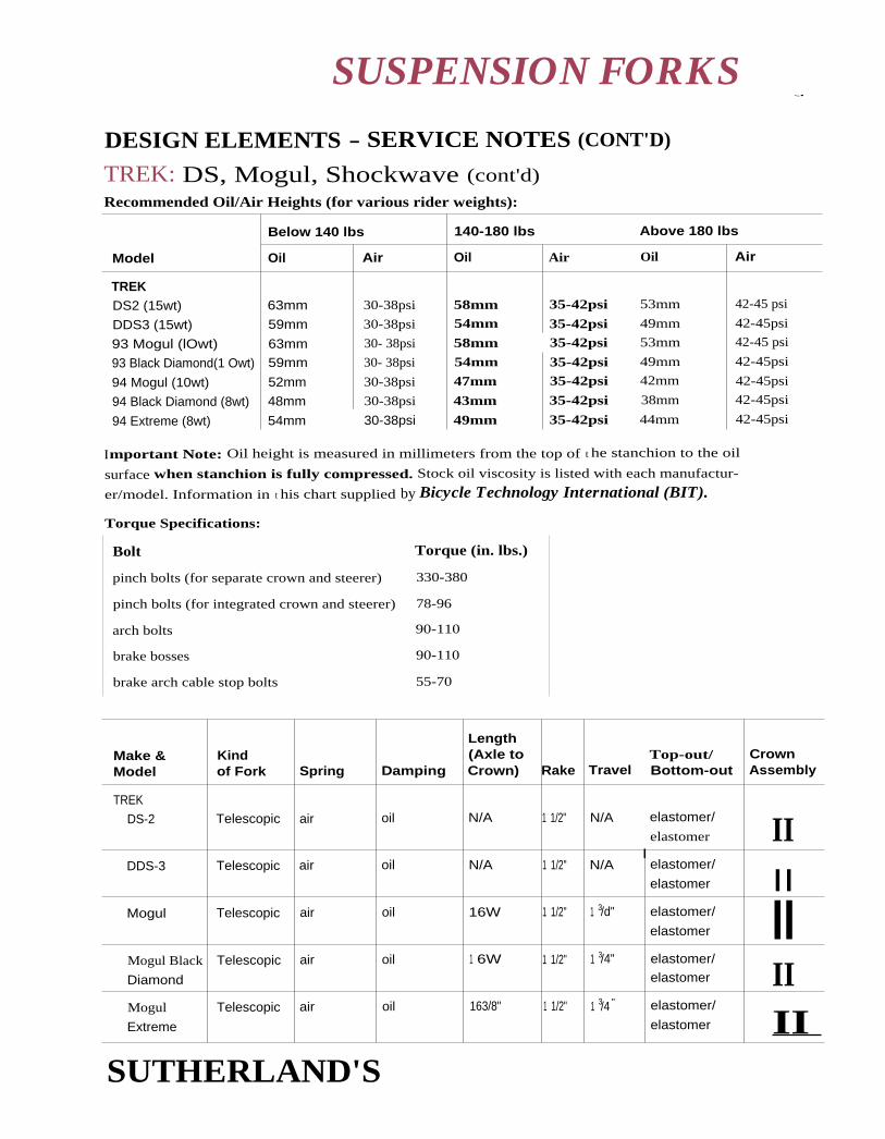
brake arch cable stop bolts 55-70
Torque (in. lbs.)Bolt
pinch bolts (for separate crown and steerer)
pinch bolts (for integrated crown and steerer)
arch bolts
brake bosses
330-380
78-96
90-110
90-110
SUSPENSION FORKS•-•
DESIGN ELEMENTS - SERVICE NOTES (CONT'D)
TREK: DS, Mogul, Shockwave (cont'd)Recommended Oil/Air Heights (for various rider weights):
Model
Below 140 lbs 140-180 lbs Above 180 lbs
Oil Air Oil Air Oil Air
TREKDS2 (15wt) 63mm 30-38psi 58mm 35-42psi 53mm 42-45 psi
DDS3 (15wt) 59mm 30-38psi 54mm 35-42psi 49mm 42-45psi
93 Mogul (lOwt) 63mm 30- 38psi 58mm 35-42psi 53mm 42-45 psi
93 Black Diamond(1 Owt) 59mm 30- 38psi 54mm 35-42psi 49mm 42-45psi
94 Mogul (10wt) 52mm 30-38psi 47mm 35-42psi 42mm 42-45psi
94 Black Diamond (8wt) 48mm 30-38psi 43mm 35-42psi 38mm 42-45psi
94 Extreme (8wt) 54mm 30-38psi 49mm 35-42psi 44mm 42-45psi
Important Note: Oil height is measured in millimeters from the top of t he stanchion to the oil
surface when stanchion is fully compressed. Stock oil viscosity is listed with each manufactur-
er/model. Information in t his chart supplied by Bicycle Technology International (BIT).
Torque Specifications:
Make &Model
Kindof Fork Spring Damping
Length(Axle toCrown) Rake
Top-out/Travel Bottom-out
CrownAssembly
TREK
DS-2 Telescopic air oil N/A 1 1/2" N/A elastomer/
elastomer IIDDS-3 Telescopic air oil N/A 1 1/2" N/A
nelastomer/
elastomer IIMogul Telescopic air oil 16W 1 1/2" 1 3/d" elastomer/
elastomer IIMogul Black
Diamond
Telescopic air oil 1 6W 1 1/2" 1 3/4" elastomer/elastomer II
Mogul
Extreme
Telescopic air oil 163/8" 1 1/2" 1 3/4 " elastomer/
elastomer II SUTHERLAND'S

Cause RemedySymptom
Dirt or grit is stuck under
the knob or on the adjuster
shaft.
Remove and clean.
Check for rust.
Grease the adjuster rod.
GENERAL
The adjuster knob is locked and
will not turn.
Fork seems to "top out" or has
a slight clunky feeling when front
wheel comes off the ground.
Rebound bumper is
insufficient.
There is not enough
rebound damping.
Remove, inspect, and replace,
if necessary.
Put in heavier weight oil or
remove grease from friction
surfaces.
Spring preload is too strong. Decrease spring preload or
install softer springs.
Adjust headset, check
clearances on bushings.
Remove and inspect fork for
signs of cracking, bending, or
stress.
Fork doesn't turn. Headset is too tight.
Steerer tube damaged.
Fork feels sluggish and
is not getting the travel it had
when it was new.
The seal is dragging.
Parts are worn or bent.
Remove, clean and lube seals.
Check stanchions for bending,
make sure they are still parallel.
Check all parts for signs of
cracking, bending, stress,
discoloration, etc.
Outer legs feel loose on inner
legs and bushings; a knock
or rock can be felt when
pushed from side to side.
Bushings or
stanchions are worn.
Measure and replace.
Fork rocks back and forth easily. See "Outer legs feel loose..."
Steerer is damaged. Remove and inspect.
Tighten.
Check steerer for damage.
Inspect underneath crown at
the steerer - check for slippage.
If there is a clean area near the
steerer with vertical scratches or
Feels like a loose headset. Headset is loose.
Steerer is pulling loose.
SUSPENSION FORKS
TROUBLESHOOTING
SUTHERLAND'S

Symptom Cause Remedy
GENERAL (cont'd)
Feels like a loose headset (cont'd).
Sliders are bent or dented.
Stanchions are scratched.
Steerer is pulling loose
(cont'd).
Crash; left bike on
roof rack and pulled
into garage.
Main seal is worn, bushing
too large, dirt is intruding.
other signs of slippage, replace
steerer/crown combo, or
tighten crown pinch bolts.
Make sure there are
mechanisms in place to prevent
steerer slippage (lips on the
steerer, circlips around the
steerer under the crown,
or a pin or bolt through
the steerer).
Replace.
is Replace stanchions, clean
everything else. Inspect and
replace bushings and seals if
necessary.
Crashed or over tightened
brake posts.
Threads were stripped.
Replace posts, apply Loctite.
Replace slider, use helicoil kit to
restore stripped threads.
Brake posts shear off.
Legs show corrosion. Bare magnesium and
aluminum are reactive
to salt.
Get the legs painted or
otherwise protected.
Stanchions are sliding on legs. Insufficient grip at crown. Tighten bolts to correct torque.
Clean oil off stanchion and
crown contact areas or
roughen surfaces.
Tire hits down tube,
handling is poor.
Crown is on backwards. Remove legs and turn crown
around.
Tire is too large.
Bottom-out bumper is
missing or too small.
Legs are clamped too low.
Tire hits crown. Check tire clearance.
Inspect bottom-out bumper,
replace if necessary.
Legs should be clamped into
the crown properly.
SUSPENSION FORKS
TROUBLESHOOTING (CONT'D)
continued on next page
SUTHERLAND'S

Symptom Remedy
Stanchions are bent.
Bearings are dirty or dry.
Bearings are the wrong size.
Cause
Wheel is riot centered in fork, Wheel is not dished.
Legs are not aligned.
Check air valve, (Schraeder cores
can be replaced). Inspect upper
seals and 0-rings.
Always loses air pressure, Seal is bad.
Stanchions are worn.
Bolt has punched
through slider.
Remove sliders. Inspect them to
be sure they are straight, and
they are parallel when
clamped into crown.
Clean and re-lubricate.
Measure and replace.
Dish wheel.
To align legs, unbolt fork brace,
loosen stanchion bolts and
align stanchions on crown
properly.
GENERAL (cont'd)
Legs are binding.
Fork pulls to one side, or
wheel tilts to one side while
fork is compressed.
AIR/OIL
Fork doesn't spring back.
Spring tension or
damping is uneven.
No air pressure.
Valving holes may be
clogged.
Adjust, check that oil in each leg
is the same height and weight.
Check air pressure.
Clean and overhaul fork.
Damping is inconsistent. Too little oil.
Oil is foaming.
Oil dirty or damping
holes blocked.
Add oil.
Use different formulation oil.
Overhaul and clean, replace oil.
Inspect all seals and 0-rings;
replace as necessary.
Measure and replace.
Check for oil leaking around
bolt hole; replace slider and
use a shorter bolt next ti me,
Oil is leaking. Seal is bad.
SUSPENSION FORKS
I TROUBLESHOOTING (CONTD)
SUTHERLAND'S

Symptom Cause 1 Remedy
AIR/OIL (cont'd)
Seals have blown out.
ELASTOMER
Elastomer is cracking.
Seals are old.
Seal retaining ring or
circlip is not seated properly,
or is missing.
Elastomer is too weathered,
worn, or over-torqued.
Replace seals.
Make sure the retaining ring or
circlip is located in the lowest
groove on the slider.
Replace and grease.
Difficulty starting the skewer There is excessive elastomer
cap because of excessive preload.
elastomer preload.
It is difficult to start the skewer. Excessive elastomer preload.
Bolt hole is not chamfered.
Bolt or bolt hole is stripped.
Decrease preload.
Decrease preload.
Be patient, keep trying.
Replace bolt or stanchion (swap
bolts and legs to see which is
stripped).
SPRING
Bottoms out too easily Spring is too weak. Replace spring with stiffer
spring or increase preload.
Spring rebounds harshly. This is inherent in some
designs.
There is not enough
damping.
Replace with different
rebound bumper.
Increase damping. For friction
damping: wipe off grease from
bushings or other friction areas.
SUSPENSION FORKS
TROUBLESHOOTING (CONT'D) r
TIRE CLEARANCECheck that the top of the tire is far enough away from the bottom of the crown. if the crown
and stanchions are separate, it may be possible to get a crown with greater clearance.
DOWN TUBE CLEARANCECompletely rotate the handlebars to check the clearance from the crown to the down tube. No mat-
ter what position the fork is in while turning, the crown should never hit the down tube. Some
manufacturers make alternate crowns that are narrower and shorter. Others add a spacer underneath
the headset crown race to bring up the head tube and angle the crown further from the down tube.
Do not raise the stanchion tubes above the fork crown. This reduces fire clearance.
I mportant note: Fork brace bolts tend to wear because of removal and overhaul; replace as needed.
SUTHERLAND'S

23
22
21
FRAME TUBES, DROP-OUTScentimeters
inches — 6927
68
- 67
26 — 66
65
64
2563
62
24 — 61
60
59
— 58
57
56
55
54
TUBING OUTSIDE DIAMETERS
Standard Steel Tubing FramesFrameMember English French Italian USA
EarlyMtn. Bikes
Top Tube 25.4mm 26mm 25.4mm 22.2mm 28.6mm
Down Tube 28.6mm 28mm 28.6mm 25.4mm 31.75mm
Seat Tube 28.6mm 28mm 28.6mm 25.4mm 28.6mm
Head Tube 31.75mm 32mm 31.75mm* Various 31.75mm
Steering
Column
25.4mm 25mm 25.4mm 25.4mm 25.4mm
Mixte Tubes 13 or14mm
13 or
14mm
13 or
14mm
* Bianchi with Special Bianchi headset uses 30mm head tube.
Chain stay, seat stay, and fork blade dimensions vary between tubing manufacturers
and it is difficult to make generalizations.
Other materials: Due to differences in physical properties, these may be engi-
neered differently and have different dimensions depending on the design con-
straints determined by the manufacturer.
19
53
52
51
50
49
48
47
46
20
18 Comparative Scale Only
45
SUTHERLAND'S

FRAME TUBES, DROP-OUTS
GEAR HANGERSThread Sizes
French 10111[11 1 nun Italian 10mm x 26 TPI
Drop-out gear hangers are most often French threaded. French, Spanish, and Japanese equip-
ment is all French threaded.
Damage to the threads of both the gear hanger bolt and the drop-out occurs when threading a10mm x lmm gear hanger bolt into a 10mm x 26 TPI hole and vice versa. The damage is slight,however, because 26 TPI is very dose to 1 thread per millimeter or 25.4 TPI. Running a tap of the
correct size through the drop-out will minimize the damage.
Rear Drop-out Threads
MakeGear HangerThreads
Rear TipAdjusters Mud Guard Eyes
Campagnolo 10mm x 26TP1 3mm x 0.5mm 5mm x 0.8mm
Huret 10mm x lmm 3mm x 0.6mm 4mm hole with no threads tappedeasily to 5mm x 0.8mm
Shimano 10mm x 1 mm 3mm x 0.5mm 5mm x 0.8mm
Simplex 9mm hole with nothreads tapped easily
to 10mm x 1 mm
3mm x 0.5mm 5.0mm hole with no threads
SunTour 1 0mm x 1 mm 3mm x 0.5mm 5mm x 0.8mm
Zeus 10mm x 1 mm 3mm x 0.5mm 5mm x 0.8mm
REPLACING FORKSViscount and Lamhert aluminum forks break without warning and should be replaced with
steel forks.
The main problem in replacing a fork is that the original is often damaged, which makes it diffi-
cult to determine its characteristics such as rake and length..
Factors That Affect HandlingRigidity: Unlike other frame members, the fork is not triangulated- it functions as a beam. The
fork receives stress from the wheel and either transmits it to the frame or dissipates it by flexing (in
the case of suspension forks, the fork dissipates much of the stress by compressing). A replacement
fork should match the original in construction and materials unless a change in ride is desired.
Rake: The rake of a replacement fork should closely match that of the old one. Small changes in
rake (on the order of 1/4") will quicken (less rake) or slow (more rake) the handling slightly.Larger changes will generally make the hike uncomfortable to ride.
SUTHERLAND'S
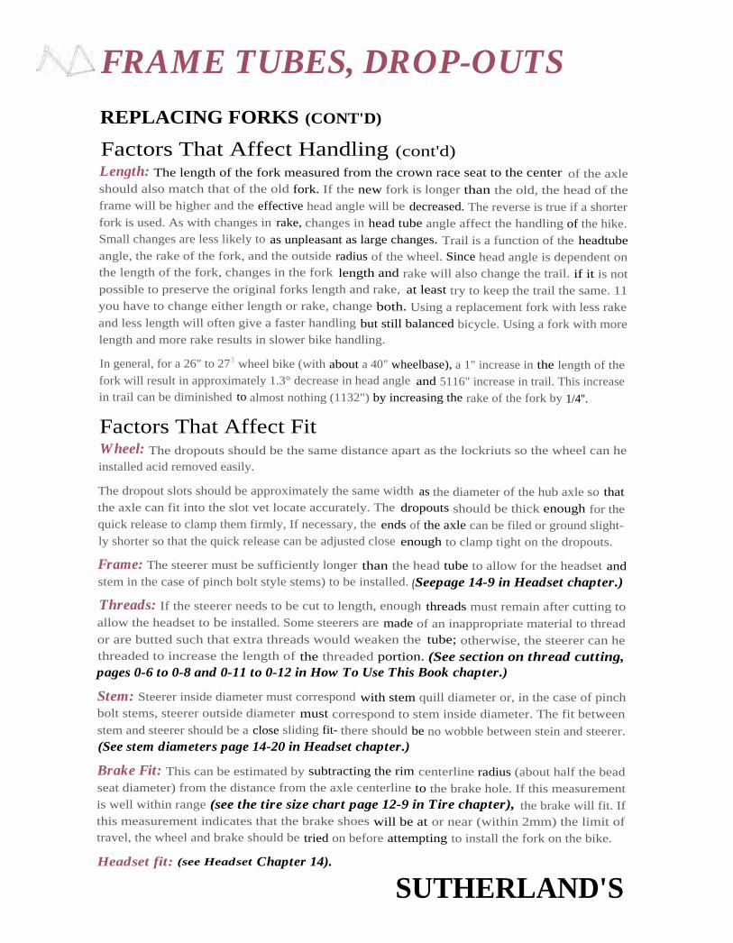
FRAME TUBES, DROP-OUTS
REPLACING FORKS (CONT'D)
Factors That Affect Handling (cont'd)Length: The length of the fork measured from the crown race seat to the center of the axleshould also match that of the old fork. If the new fork is longer than the old, the head of theframe will be higher and the effective head angle will be decreased. The reverse is true if a shorterfork is used. As with changes in rake, changes in head tube angle affect the handling of the hike.Small changes are less likely to as unpleasant as large changes. Trail is a function of the headtubeangle, the rake of the fork, and the outside radius of the wheel. Since head angle is dependent onthe length of the fork, changes in the fork length and rake will also change the trail. if it is notpossible to preserve the original forks length and rake, at least try to keep the trail the same. 11you have to change either length or rake, change both. Using a replacement fork with less rakeand less length will often give a faster handling but still balanced bicycle. Using a fork with morelength and more rake results in slower bike handling.
In general, for a 26" to 27 11 wheel bike (with about a 40" wheelbase), a 1" increase in the length of thefork will result in approximately 1.3° decrease in head angle and 5116" increase in trail. This increasein trail can be diminished to almost nothing (1132") by increasing the rake of the fork by 1/4''.
Factors That Affect FitWheel: The dropouts should be the same distance apart as the lockriuts so the wheel can heinstalled acid removed easily.
The dropout slots should be approximately the same width as the diameter of the hub axle so thatthe axle can fit into the slot vet locate accurately. The dropouts should be thick enough for thequick release to clamp them firmly, If necessary, the ends of the axle can be filed or ground slight-ly shorter so that the quick release can be adjusted close enough to clamp tight on the dropouts.
Frame: The steerer must be sufficiently longer than the head tube to allow for the headset andstem in the case of pinch bolt style stems) to be installed. (.Seepage 14-9 in Headset chapter.)
Threads: If the steerer needs to be cut to length, enough threads must remain after cutting toallow the headset to be installed. Some steerers are made of an inappropriate material to threador are butted such that extra threads would weaken the tube; otherwise, the steerer can hethreaded to increase the length of the threaded portion. (See section on thread cutting,pages 0-6 to 0-8 and 0-11 to 0-12 in How To Use This Book chapter.)
Stem: Steerer inside diameter must correspond with stem quill diameter or, in the case of pinchbolt stems, steerer outside diameter must correspond to stem inside diameter. The fit betweenstem and steerer should be a close sliding fit- there should be no wobble between stein and steerer.(See stem diameters page 14-20 in Headset chapter.)
Brake Fit: This can be estimated by subtracting the rim centerline radius (about half the beadseat diameter) from the distance from the axle centerline to the brake hole. If this measurementis well within range (see the tire size chart page 12-9 in Tire chapter), the brake will fit. Ifthis measurement indicates that the brake shoes will be at or near (within 2mm) the limit oftravel, the wheel and brake should be tried on before attempting to install the fork on the bike.
Headset fit: (see Headset Chapter 14).
SUTHERLAND'S

SEAT POSTS
.+ SEAT POST SIZESTubing inside diameters vary so much from maker to maker that no size listed here can be con-
sidered correct until t he seat post has actually been tried in the bicycle.
Conventional Steel Tubing FramesNational Quality TubingStandard Common Tubing Plain Gauge Butted
English 25.4 (1") 26.4 27.0
25.8 (1-1/64") 26.6 27.2*
26.2 (1-1/32") 27.4
French 25.0 26.2 26.4
25.0 26.6*
25.826.0
Italian 25.0 26.0 26.8
25.8 26.2 27.0
26.0 27.2
Japan 25.8 26.2 26.4
26.2 26.8 26.6
26.827.0
27.2
USA 22.2 (7/8") (.875") See English
20.6 (13/16') (.812")
* Most common
Other TendenciesMost Common Next Most Common
BMX
Steel .875" (7/8") (22.2mm) .812" (13/16") (20.6mm)
Mountain
Steel 26.8 26.6
Aluminum
Glued 25.4 25.0
Welded 27.2 27.4
SUTHERLAND'S

SEAT POSTS
SOME UNUSUAL SEAT POST SIZES
Fisher Mountain BikesSteel - 28.6mm
Aluminum - 31.6mmTitanium (current production) - 27.4min
(earlier production) - 29.4mm
Mongoose IBOC SignatureTitanium with CroMo rear triangle - 29.4mmOlder, all-titanium model - 27.2mm
Alex Moulton AM Series1-3/8" (35.0mm)
Charlie Cunningham and IndianOversized - 1-3/8" (34.9mm)Some road hikes- I-1/4" (31.77min)
KleinCurrent production - 27.2mm
Earlier production - 27.4mm
CannondaleCurrent production - 27.2mm1985 model 500 - 7/8 " seat post and shim
Schwinn M.O.S.29.8mm
Raleigh Twenty, Bridgestone Picnica(and many other folding bikes with oversized posts)28.6mm
Bikes with square seat posts1" square
SEAT POST CLAMP BOLTISO - 8mm xlmm
SUTHERLAND'S

INTERNALMULTI-SPEED
HUBS
CONTENTS
16
Sachs 7-SpeedParts diagram ...................... 2
How it works ....................... 3
Alignment.............................. 3
Levers and cables ................ 4
Shifter operation ................. 4
Wheel removal ..................... 5
Reinstall sprocket ................ 5
Repair lever/clickbox ......... 5
Troubleshooting chart ..... 6,7
Compatibility ....................... 8-10
Disassembly
Torpedo Super 7 ........... 11-13
Cleaning and lubrication 1 4
Assembly
Torpedo Super 7 ........... 1 5-19
Gear table ............................. 19
Sachs 5-SpeedParts diagram .............................. 20
How it works ................................ 21
Alignment ...................................... 21
Levers and cables ........................ 22
Shifter operation ....................... 22Pull chain ................................. 22Clickbox ............................. 22-23
Wheel removal .......................... 23
Disassemblysprocket, shifter .................. 23
Reinstallsprocket, wheel ............ 23-24
Repair lever/clickbox ................ 24
Troubleshooting chart ........... 6,7
Compatibility ......................... 8-10
DisassemblyTorpedo Pentasport ......25-28
Cleaning and lubrication .......... 29
Assembly
Torpedo Pentasport ......30-34
Gear table ...................................... 34
Sachs 3 X 7Parts compatibility .............. 35-36
Shimano 7-SpeedParts diagram ...................... 37
How it works ....................... 38
Shifter operation ................. 39
Wheel removal .................... 40
Troubleshooting chart ..... 41-42
Parts list ................................. 43-44
Disassembly .......................... 45-46
Cleaning and lubrication 47
Assembly ............................... 48-50
Gear table ............................. 51
SUTHERLAND'S

2422 23 (5•1
19 V‘50
51
1 5
13
29
2830
26
rGq
32c 155511
32a32b
z
z

INTERNAL MULTI-SPEED HUBS
SACHS TORPEDO SUPER 7-SPEEDCOASTER BRAKE/CLICK BOX HUB
How It WorksOperation of the right side of the huh is similar to that of Sachs three-speeds:
In the lower gears, the sliding clutch connects the driver with the gear ring, but pulls the gear ring
to the right so its pawls are disengaged from their ratchet inside the huh shell. Drive is through
the planetary gear system to the pawls on the brake cone assembly at the left side of the hub.
In 4th (middle gear), the sliding clutch still connects the driver to the gear ring, but the gear
ring is released to the left so it drives its pawls directly, while the brake cone pawls freewheel
backward slowly.
In the higher gears, the sliding clutch connects the driver to the planet carrier, and drive is
through the planetary gear system to the gear ring; the brake cone pawls freewheel backward.
Drive to the coaster brake is through the gear train: there is no special set of rear-facing pawls as
with the Sturmey-Archer S3C hub. Brake effectiveness therefore is the same in the three highest
gears (1/1 drive to planet carrier), better in 4th arid 3rd (1.236/1) and better yet in 2nd (1.479/1)
and 1st (1.685/1). Brake drive is, however, positive, as the gear ring is spring-loaded in both
directions: the clutch engages the gear ring and planet cage at the same time during the only
shift with a possible "neutral" position, between 4th and 5th. If the planetary gear train fails,
brake drive will, however, be lost in 1st through 4th gears.
AlignmentThis hub has an overlocknut spacing of 130 mm, a rear chainline of 48 mrn arid a minimum
front chainline of 44mm (when the sprocket dishing faces toward the wheel). Many retrofits of
this hub will require realignment of the rear triangle and a longer bottom-bracket axle.
Spoking flange diameter is 75 mm. The hub is available only with 36 spoke holes, according to
Sachs literature.
The wide gear range of this hub requires a lower chain drive ratio than other multi-speed hubs. A
24-tooth sprocket is provided. For example, this will provide a gear range of 31 to 87 inches
(2.45 to 6.96 meters development) when used with a 46 tooth chainwheel and 27-inch rear
wheel. Other, smaller Sachs, Sturmey, Shimano etc. sprockets will fit and are useful when
installing this hub in a small wheel. Generally, the direct drive, middle gear should be about 5]
inches (4.10 meters).
The provided 24-tooth sprocket is usable with 3/32" derailleur-type chain or with 1/8' chain,
though it is stamped around the mounting hole to make it take up the same space on the driver
as a thicker sprocket made only for 1/8" chain.
SUTHERLAND'S

INTERNAL MULTI-SPEED HUBS
Shift Levers and CablesI mproper adjustment is the most common cause of problems with 3-, 4-, 5- and 7-speed hubs.
Many people have quit riding bikes because their huh slipped out of gear when they were stand-ing up on the pedals. Always check trigger and cable operation before deciding to overhaul a huh.
For the 7-speed's push-pull cable to work properly, all fittings must he tight enough not to creepalong the frame and the cable must be free of kinks and knots.
Three types of shift levers are listed in the literature: a single-lever thumhshifter, with mountinghardware for the front or rear of the handlebar, and a twist shifter. A push-pull shifter cable isused, like the old Shimano Positron cables (Refer to Sutherland's Handbook of Coaster Brakesand Internally Geared Flubs).
Cable lengths in the parts list are about 55 through 67 inches in increments of 50mm. The cableand its housing cannot be shortened or otherwise altered, hence the multiple assemblies with
different stock numbers. Measure the old cable before ordering a new one.
The cable's motion is translated into motion of two concentric pushrods by . a cam assembly inthe clickbox which attaches to the right end of the hub axle.
The shift lever is sold as a separate item. Clickbox and cable are a single item, though they could
be disassembled, allowing clickbox or cable to he replaced independently (see instructionsbelow). The clickbox, with its plastic shell, is somewhat vulnerable even when equipped with theprotective sted guard provided.
Testing Shifter OperationCheck shift lever/cable/clickbox assembly for straightness of cable, cracks to housings and otherobvious problems.
The inner pushrod (16) selects which sun gear is in use, and the outer pushrod (17) selects thedirection in which power passes through the gear train. Rushrod (and clickbox paddle) positionsare (o
W out, m = middle, i = in):
Gear 1 2 3 4 5 6 7
outer q q o m i i i
inner o m i I i m o
To inspect the clickbox for correct operation: with the clickbox disconnected from the hub, shift
to 4th gear and then to 1st. Now push both paddles inside the axle hole of the clickbox as faraway from you as possible. They should move smoothly and easily. Now shift from first through
third gear; the central paddle should move toward you in two distinct steps. As you continue tofourth and fifth gear, the outer paddle should move toward you in two distinct steps.
Now shift to 7th gear and push the central paddle down. It should not he possible to push the
outer paddle down. As you shift down from 7th to 6th and 5th, the central paddle should move
toward you in two distinct steps. Note: you may test the clickbox and the shifter parts of the hubat the same time by installing the axle, guide sleeve and pushrods into the clickbox after
installing both axle keys and the clutch but before installing the gear ring.
SUTHERLAND'S
INTERNAL MULTI-SPEED HUBS
WHEEL REMOVAL AND DISASSEMBLY OF SHIFTERAND SPROCKET PARTS:Loosen the knurled bolt on the clickbox (S27), and pull the clickhox off the end of the axle.
Remove guide sleeve (S18) (snap fit). Remove inner and outer push rods (516, S17). Remove these
parts before removing the wheel to avoid possible damage.
Remove wheel as usual after loosening axle nuts and removing brake arm clip bolt.
Remove axle nuts, tab washers and clickbox guard if hub will he rebuilt.
Note the direction of sprocket dish. Remove snap ring, sprocket and large dust cap from driver if
necessary to replace.
REINSTALLATION OF SPROCKET, WHEEL AND CLICKBOXTo avoid possible damage, do not install pushrods, clickbox guide or clickbox before installing
wheel into drop-outs.
Check for correct direction of sprocket dish, then replace large dustcap, sprocket and snap ring.
Place wheel in drop-outs: for a new installation, place one tab washer on outside of each drop-
out, with tabs in closed end of drop-out slot, unless drop-out thickness is over 5.5 mm (7/32");then place one tab washer inside and one outside left drop-out. Install but do not yet tighten the
brake arm clip on the left chainstay. Install clickbox guard on the right end of the axle, and then
install the axle nuts. Adjust drive chain slack, making sure that brake arm does not bind. Tighten
the brake arm clip bolt.
Oil pushrods (516, 517) lightly and install them into axle, then install guide sleeve (518) withprotruding nose at inner end and internal tab in slot of outer pushrod. Rotate guide sleeve until
the nose is at the top.
Place shift lever in 1st gear position. Push clickbox onto the axle, with nose of guide sleeve engag-ing in groove of clickhox housing. Tighten knurled knob. No cable adjustment is necessary.
REPAIR OF SHIFT LEVER/CABLE/CLICKBOXShift levers may be replaced and interchanged by removing the Phillips-head screw which
holds the lever body together. The cable has a barrel head and may be slipped in and out of itsmounting slot.
The clickbox end of the cable has a plastic rack gear molded onto it; adjustment of cable lengthis therefore not possible. However, it is possible with care to replace a cable or clickbox withoutreplacing the other. After removing the several small screws which hold the clickbox together,
the cable and rack gear may be lifted out. When reassembling, take care that the cams and cam
followers are correctly installed. You must time the clickbox gears: with the shift lever in
4th gear position, the upper cam follower is on middle land of its cam, and the lower one is
pushing to max.
SUTHERLAND'S

'.INTERNAL MULTI-SPEED HUBS
Troubleshooting Chart - Sachs 5 & 7 Speed HubsResulting from wear, improper Resulting from improper
SYMPTOMS lubrication or abuse assembly or installation
Brake cone pawls (19) faulty Brake cone pawls (19)improperly installed
Clutch (46) teeth broken
Improper lubrication —gummed or dirty
Gear ring spring (49) damaged
[Gear ring pawls (48) faulty
Slips in 1st — 3rd gear----
Slips in 4th gear --
Slip in Sth — 7th gear--
Jumps from 4th to 3rd
Jumps from higher gear to 4th
4th instead of higher gears
Wear or damage to clickbox
12-turn spring (52)damaged
Gear ring spring (49) missing
Gear ring pawls (48)improperly installed
Clickbox improperly installed
12-turn spring (52) missing
Jumps from lower gear to 4th
Jumps from 4thto higher gear
Wear or damage to clickbox
7 turn spring (43) weakor damaged
Clickbox improperly installed
Pedals driven forward--while coasting
Stiff running, noisy
Jammed
Sluggish shifting - -
Shift lever will notmove above 4th gear
Too much play in axle
No brake
Weak brake
Chain too tight
Bearings too tight or loose
No/wrong lubrication
Ball cage damaged/broken
Dustcap damaged
Brake lever (1 3) forcing coneout of line
Loose or broken partsinside hub
Axle C-clip (35) broken
Axle bent
Clickbox damaged
Pushrods bent or dirty
Plastic washer (33) onwrong side of C-clip (35)
Bearings loose or damaged
Friction spring (20) weak orworn
Wrong lubricant
Brake parts glazed or worn
Planet gears (25) mistimed
Ball cage reversed
Dustcap reversed
Axle E-clip (24) missing
Friction spring (20) reversed
Axle C-clip (35) missing
Clickbox guide (518) absent
Friction spring (20) missing
Parts numbers in parentheses refer to parts chart and exploded drawing.
SUTHERLAND'S

INTERNAL MULTI-SPEED HUBS ti}
Troubleshooting Chart - Sachs 5 & 7 Speed HubsResulting from wear, improper Resulting from improper
SYMPTOMS lubrication or abuse assembly or installation
Brake too strong or jerky
Brake does not release __
No brake in 1st — 4th gears
No drive except 4th gear
1st instead of 2nd and 3rd --___7th instead of 6th and 5th
3rd instead of 1st and 2nd5th instead of 6th and 7th
Brake lever (13) loose atchainstay
Brake cylinder (16) unlubricated
Axle (32) loose in dropouts
Unlubricated thrust surfacebetween axle (32) andplanet carrier (25)
Planet carrier (25) andbrake cone (19) threadsworn or chipped
Left axle key (32b) broken orstripped
Damaged or worn clickbox
Short (center) left axlekey spring (32a) damaged
Left axle key long returnspring (32d) jammed
Axle key guide rod (32c) bent
Thrust washer (26) missing
Left axle key (32b) missingor misaligned
Inner pushrod (51 7) absent
Short left axle key spring (32a)(toward middle of axle)missing
Left axle key long returnspring (32d) missing
Slips in 2nd and 6th gear
No brake in 2nd gear
I
2nd instead of 3rd,6th instead of 5th
Middle sun gear (30) stripped
Spring (28) weak, damaged
Small sun gear (29) reversed
Middle sun gear (30) reversed
Spring (28) missing
Parts numbers in parentheses refer to parts chart and exploded drawing.
SUTHERLAND'S
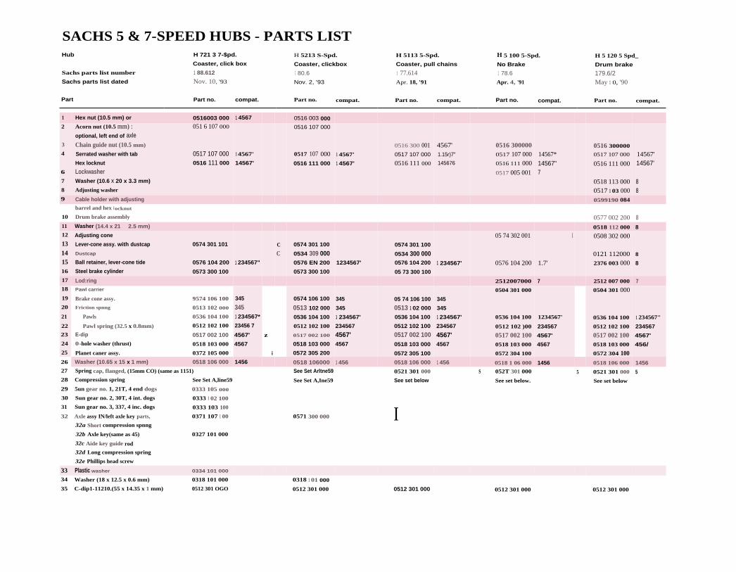
SACHS 5 & 7-SPEED HUBS - PARTS LISTHub H 721 3 7-$pd. H 5213 S-Spd. H 5113 5-Spd. H 5 100 5-Spd. H 5 120 5 Spd_
Coaster, click box Coaster, clickbox Coaster, pull chains No Brake Drum brakeSachs parts list number 1 88.612 1 80.6 1 77.614 1 78.6 179.6/2Sachs parts list dated Nov. 10, '93 Nov. 2, '93 Apr. 18, '91 Apr. 4, '91 May 1 0, '90
Part Part no. compat. Part no. compat. Part no. compat. Part no. compat. Part no. compat.
1 Hex nut (10.5 mm) or 0516003 000 1 4567 0516 003 0002
3
4
6
7
8
Acorn nut (10.5 mm) : 051 6 107 000
optional, left end of axleChain guide nut (10.5 mm)
Serrated washer with tab 0517 107 000Hex locknut 0516 111 000
LockwasherWasher (10.6 x 20 x 3.3 mm)
Adjusting washer
1 4567'
14567'
0516 107 000
0517 107 000
0516 111 000
1 4567'
1 4567'
0516 300 0010517 107 000
0516 111 000
4567'1.15r)7"
145676
0516 3000000517 107 0000516 111 000
0517 005 001
14567*
14567"7
0516 300000
0517 107 000
0516 111 000
0518 113 0000517 1 03 000
14567'14567'
88
9 Cable holder with adjusting 0599190 084
10
barrel and hex locknut
Drum brake assembly 0577 002 200 811 Washer (14.4 x 21 2.5 mm) 0518 112 000 812
13141516
Adjusting cone
Lever-cone assy. with dustcap 0574 301 101
Dustcap
Ball retainer, lever-cone tide 0576 104 200
Steel brake cylinder 0573 300 100
1 234567"
C
C0574 301 100
0534 309 0000576 EN 200
0573 300 100
1234567'
0574 301 100
0534 300 0000576 104 200
05 73 300 100
1 234567'
05 74 302 001
0576 104 200
I
1.7'
0508 302 000
0121 1120002376 003 000
8
8
17 Lod:ring 2512007000 7 2512 007 000 718
19
20
21
22
23
24
25
Pawl carrier
Brake cone assy. 9574 106 100
Friction spnng 0513 102 000
Pawls 0536 104 100
Pawl spring (32.5 x 0.8mm) 0512 102 100
E-dip 0517 002 100
0-hole washer (thrust) 0518 103 000
Planet caner assy. 0372 105 000
345
3451 234567*
23456 7
4567'
4567
z
i
0574 106 100
0513 102 000
0536 104 100
0512 102 100
0517 002 100
0518 103 000
0572 305 200
345
345
1 234567'
234567
4567'4567
05 74 106 100
0513 1 02 000
0536 104 100
0512 102 100
0517 002 1000518 103 000
0572 305 100
345
345
1 234567'
234567
4567'4567
0504 301 000
0536 104 100
0512 102 )00
0517 002 1000518 103 000
0572 304 100
1234567'
234567
4567'
4567
0504 301 000
0536 104 100
0512 102 100
0517 002 1000518 103 000
0572 304 100
1 234567"
234567
4567'
456/
26 Washer (10.65 x 15 x 1 mm) 0518 106 000 1456 0518 106000 1 456 0518 106 000 1 456 0518 1 06 000 1456 0518 106 000 145627
28
29
30
31
32
Spring cap, flanged, (15mm CO) (same as 1151)
Compression spring See Set A,line59
5un gear no. 1, 21T, 4 end dogs 0333 105 000
Sun gear no. 2, 30T, 4 int. dogs 0333 1 02 100
Sun gear no. 3, 337, 4 inc. dogs 0333 103 100
Axle assy IN/left axle key parts, 0371 107 1 00
32a Short compression spnng
32b Axle key(same as 45) 0327 101 000
32c Aide key guide rod
32d Long compression spring
32e Phillips head screw
See Set Arltne59
See Set A,Ine59
0571 300 000
0521 301 000
See set below
I
S 052T 301 000
See set below.
5 0521 301 000
See set below
5
33 Plastic washer 0334 101 000
34
35
Washer (18 x 12.5 x 0.6 mm) 0318 101 000
C-dip1-11210.(55 x 14.35 x 1 mm) 0512 301 OGO
0318 1 01 000
0512 301 000 0512 301 000 0512 301 000 0512 301 000

1
1
1
Cr Part36 Sun gear set36a Small sun gear, 6 end dogs
i 36b Large sun gear, 30T, 6 int. dogs
4ril
X
l 39 Axle 159 mm40 Axle 168 mm
41 Axle 171 mm
2 Spring cap43 Compression spring
44 Spring cap
45 Axle key (same as 32b)46 Splined clutch47 Gear ring assy. with
48 Pawts
Z 49 Ring spring50 Large compression spring
52 Spring cap, flanged (15mm OD),(same as #27) 0521 301 0002
See Set A
Cis
53
...
0376 102 000
54 0372104 000
56 0321 101 000
57 1004... ...58 0512 011 000
59
0391 004 000(Set A)
— 0324 103 000 blue0369 135 1000369 135 101
Part no. compat.
0591 302 0010533 305 0000533 307 000
See Set A, line59See Set A, line590527 301 1000572 301 1000581 300 000
0536 109 100 47
0512 303 000See Set A. line590521 301 000 ASee Set A line590576 300 000
0572 302 0000508 300 000
0521 303 000
0512 011 0000591 304 000(Set A)
I — 0524 300 000 red0 369 135 100
0369 135 101
Part no, compat.
See Set A,line6lSee Set A,line61See Set A,line61
0327 101 00005 72 301 000
0381 100 000
0536 109 100 47
0512 303 000See Set A
A
55 0308 024 000
Cornpression spring
Ball cage- driver side
DriverD .Fixed cone (7-spd: serrated)
Sprocket dustcapSprockets XCirclip X
Spring set (no axle springs)
including items 27, 28,43, 44, 50, 51, 52
59 Set compression springs
60 Spring cap set -flanged (15
mm 00): flanged (21 nim OD);two-step (21 mm 001
61 Spring set (no axle springs)including items 28 , 42. 43,44, 50, 51, 52
62 Planet gear timing aid63 Special grease type A, 35g64 SpeciA crease type A. 2 x 250q
INTERCHANGES WITH:1. Duomatic 102 and 101 (if brake part, 102 only)2. Automatic R 2110
3. Automatic A 2110
4. 3 spd. coaster H 31 1 1
S. 3 spd. coaster 515
6. 3 spd. 415
7. 3 spd. H 3102, and 3 sp. drum brake H 3120 except brake assemblyand left side bearing parts
8. These brake assembly and left side bearing parts interchangewith 3 spd. drum brake H 3120
Interchangeable in one direction.
A. Also see parts set A below
C. Cosmetic difference only.
X. See Sprocket interchangeability page 1-3 Sutherland's Handbookof Coaster Brakes and Internal Geared Hubs
S. Also see parts set below
Z. New style plastic adjuster/cable clamp works with new style pull rod.
Appears fully interchangeable despite part number difference.Has been checked against H3111.
I Vertical lines between numbers indicates parts are not interchangeable.
+ Included in axle set #32 from Sachs.
Part no. compat. Part no. compat. Part no. com port.
0591 302 001 0591 302 001 0591 302 001
0533 305 000 0533 305 000 0533 305 000
0533 307 000 0533 307 000 0533 307 000
0509 300 001 1 0509 300 DOO
0509 301 0000509 303 000
0521 308 000 S 0521 308 000 5 0521 308 000 SSee set below See set below See set below
0521 300 000 S 0521 300 000 5 0521 300 000 5
0527 100 200 456' 0527 100 200 456' 0527 100 200 456"
0572 301 000 0572 301 000 0572 301 000
0581 300 000 0581 300 000 0581 300 000
0536 109 100 47 0536 109 000 47 0536 109 100 470512 303 000 0512 303 000 0512 303 000
See set below See set below See set below
0521 301 000 S 0521 301 000 S 0521 301 000 SSee set below See set below See set below
0576 300 000 0576 300 000 0576 300 000
0572 302 000 0572 302 000 0572 302 0000508 300 000 0508 300 000 0508 300 000
0521 303 000 0521 303 000 0521 303 000
1 004... ... 1004... ... 1004... ...
0512 011 000 0512 011 000 0512 011 000
0591 301 001 0591 301 00 1 0591 301 001
0591 302 000 0591 302 000 0591 302 000
0524 300 000 red — 0524 300 000 red —0524 300 000 red
0369 135 100
0369 135 101

SHIFTER PARTS SACHS 5 & 7-SPEED HUBSHub
Sachs parts list numberSachs parts list datedPart
51 Trigger, Front of handlebar
H 7213 7-5p4i.Coaster, clickbox188.612Nov. 10, '93Part no. compat0386 008 000
H 5213 5-Spd.Coaster, clickbox180.6Nov, 2, '93Part no. compat.0586 318 000
H 5313 5-Spd.Coaster, pull chains177.6/4Apr. 18, '91Part no. Compat.
H 5100 5 Spd,No Brake178.6Apr. 4, '91
Part no. compat.
H 5120 5 Spd.Drum brake179.6/2May 10, '90Part no. compat.
L 5501 black 00 0586 307 030 00 0586 307 030 00 0586 307 030L 5501 white/gray 00 0586 307 001 00 0586 307 001 00 0586 307 001
L 5501 black/pink 00 0586 308 100 00 0586 308 100 00 0586 308 10052 Trigger, rear of handlebar 0386 004 000 0586 311 DOO53 Twist•grip shift control 0586 321 00054 Stem shifter, 1-lever
with boll 0586 301 000 0586 301 000 0586 301 000L 5502 black 00 0586 301 300 00 0586 301 300 00 0586 301 300L 5502 white/gray 00 0586 304 100 00 0586 304 100 00 0586 304 100
55 Stem shifter, 2-lever, 88 1186 740 089 88 11 86 740 089 88 1186 740 089I. 5502 black
S6 Left ATE trigger, 82 1186 837 021 82 1186 837 021 82 1186 837 021MA 82 2-position
57 Right ATI3 trigger, 82 1186 836 021 82 11 86 836 021 82 1186 836 021MA $2 3-position
58 Adjuster/cable clamp (2x) 0570 117 000 4567 0570 717 000 4567 0570 117 000 456759 Pull chainirod (long) 0187 102 000 2 0187 702 000 7 0187 102 000 7510 Bolt, M6 x 16 1615 001 004 12345 1615 001 004 12345 1675 001 004 12345S31 Clamp 0326 12345 0376 . .. 12345 0326... . 12345512 Hex nut M6 0242 129 002 12345 0242 129 002 12345 0316 057 002 12345513 Pull chain/rod (short) 0587 102 000 4567 Z 0587 102 000 4567 Z 0587 102 000 4567 2514 Clickbox guard 0520 302 000 0520 302 000515 Set B: shift parts 0391 004 001 0591 304 001516 Inner pushrod See Set 8 See 5et I517 Outer pushrwl See Set B See 5e1 B
518 Cliclibrix guide 0334 103 000539 Clickbox with 1300 mm cable 0586 319 007520 Clickbox with 1400 mm cable 0386 009 000 0586 319 003
S21 Clickbox with 1450 mm cable 0386 009 001 0586 319 004
522 Clickbox with 1500 mm cable 0386 009 002 05136 319 000S23 Clickbox with 1550 mm cable 0386 009 003 0586 319 006
524 Clickbox with 1600 mm cable 0386 009 004 0586 319 00152S Clickbox with 1650 mm cable 0386009 005 0586 319 005526 Clickbox with 1700 mm cable 0386 009 006 0586 319 002527 Knuded boll for clickbox 0515 307 000 0515 307 000
(See page 16-9 for interchangeability notes.)

INTERNAL MULTI-SPEED HUBS
DISASSEMBLY AND ASSEMBLY INSTRUCTIONSFOR SACHS TORPEDO SUPER 7 HUB
1 DISASSEMBLYClamp axle in axle vise, Phillips screw head end facing up.Unscrew the two locknuts (5) from each other using a 17 mm
cone wrench and a 17 mm open end or box-end wrench;
remove the locknuts. Remove lever cone assembly (13), ball
ball retainer (15) and brake cylinder (16).retainer
brakecylinder
hub shell
frictionspring
brake coneassembly
2 DISASSEMBLY
Litt off hub shell. Rotate brake cone assembly (19) counter-
clockwise and remove.
planetcarrier
SUTHERLAND'S

driver
ballretainer
long 12-turn-spring
spring cap —
large spring
E-clip
-4* D-hole thrustwasher
-4g— planet carrier
___----- thrust washer
'-- short spring
29
30 sun gears
-- 31
INTERNAL MULTI-SPEED HUBS
SACHS TORPEDO SUPER 7 (CONT'D)
3 DISASSEMBLYInvert assembly in axle vise — end of axle with Phillips headscrew down, grooved end up. Using a 17mm open-end
wrench, unscrew the fixed cone (55). Remove the driver(54), long 12-turn spring (52) with spring cap (careful –spring cap can stick in splined clutch) (51), large spring (50),
ball retainer (53), gear ring (47) and splined clutch (46).
Compress 7-turn spring with spring cap (43) and remove
axle key (45). Remove outer spring cap (44), 7-turn spring(43) and inner spring cap (42).
spring cap
7- turn--spring
axle key
4 DISASSEMBLYInvert assembly in axle vise — Remove axle E-clip (23) and D-holethrust washer (24). Lift off planet carrier (25). Remove the round-
hole thrust washer (26) from inside the planet carrier or from theaxle. Sometimes grease causes washer to stick to planet carrier. Theplanet carrier is a unit. Do riot attempt to remove the planet pin-ions. Remove short compression spring (28) and the small diame-ter, medium diameter and large diameter sun gears (29, 30, 31).
SUTHERLAND'S

driver
C-clip(under theplastic washer,not visible)
Phillipshead screw
\.1n-) long
+.111- compression-A spring
axle keyguide rod
INTERNAL MULTI-SPEED HUBS/ }
SACHS TORPEDO SUPER 7 (coNro)
SUBDISASSEMBLIES
AxleTo prevent the spring behind Phillips head screw (32e) from flying out,
grasp the screw with one hand as you turn it with the other, then releasethe spring carefully. Carefully remove the Phillips head screw (32e).
Remove long compression spring (32d), axle key guide rod (32c), axlekey (32h), and short compression spring (32a). Remove formed plastic
washer (33) and steel washer (34). Only if necessary for replacement,
remove C-clip (35).
DriverRemove dustcap with a thin-bladed screwdriv-er. Work slowly around dustcap to avoid
deforming it. Lift out ball retainer. Note: parts
list shows driver as an assembly with the inter-
nal ball cage and dustcap. "fhe same ball cage is
found also in the 5-speed hubs, different from
that used in Sachs 3-speed hubs. A mechaniccould replace the bearing balls or the cage (Star
0103 2511.
Brake ConeTo remove pawls (21), pull outward
until end of pawl spring (22) clears
groove, then ease pawl spring off theend of brake cone. Remove friction
spring (20) from brake cone only if it is
to he replaced.
frictionspring
brake -cone
pawl ftipawl
spring
Gear RingTo remove pawls (48), pry straight end of
pawl spring (49) out of groove and ease
over end of gear ring (47).
pawl
pawl spring
gear ring ring --pi.-
SUTHERLAND'S

JINTERNAL MULTI-SPEED HUBS
SACHS TORPEDO SUPER 7 (CONT'D)
CleaningClean all parts, including outside of hub shell, in a suitable solvent. Be very careful not to intro-
duce dirt or grit atter cleaning. Clean t he planet cage with a brush or air, not by immersion.
Points to check1. Pawls (21, 48) and ratchets for rounding and chipping.
2. Gear ring (47), planet gears of planet carrier (25) and sun gears (29, 30, 31) for worn and
chipped gear teeth.
3. Planet carrier (25), gear ring (47), clutch (46), inside of driver (54) sun gears (29, 30, 31),
brake cylinder (16) and lever cone (13) for worn or rounded splines or dogs.
4. Bearing surfaces of lever cone (13), hub shell, driver (54), fixed cone (55), ball retainers (15,
53), and inside driver (54) for wear or pitting.
5. Brake cylinder (16) and braking surface inside hub shell for wear and glazing.
6. Brake cone (19) for worn serrations.
7. Friction spring (20), compression springs (28, 43, 52), two internal axle springs (32a, d) and
pawl springs (22, 49) for size and tension (manufacturer recommends replacing pawl springs
at overhaul).
8. Axle (32), axle key guide rod (32C) and push rods (516, 51 71 for straightness.
9. Dust caps of lever cone and driver (13, 54), sprocket dustcap (56), spring caps (42, 44, 51),
circlips (23, 35, sti) and ball retainers (15, 53), and inside driver (54) for straightness.
10. All threaded parts for worn or damaged threads.
11. Axle keys (32b, 45) and axle slots (32) for rounding or chipping.
LubricationTo lubricate the planet gear bearings, stand the planet carrier on its wide end and apply 2 to 3
drops of oil at the hearing pins where visible under retaining ring, turning the gears to aid the oil
in penetrating.
Lubricate bail cages by filling the spaces between balls will' grease. Be careful not to grease pawls
or clutch. Lubricate hub shell, brake shoe and friction spring liberally with a high-temperature
grease for steel brake shoes. Oil, never grease, brake cone and gear ring with a good cycle oil.
( WD-40 is too light for lasting lubrication, 3-in-1 oil gums up with age.)
SUTHERLAND'S

INTERNAL MULTI-SPEED HUBS"
SACHS TORPEDO SUPER 7 (CONT'D)
SUBASSEMBLIES
Gear RingInstall pawls (48) under hooked, circular pawl spring (49).
Pawls must point clockwise when viewed from small end ofgear ring. Hooked end of pawl spring should lie in the slot
that intersects pawl spring groove.
pawl
pawl spring
gear ring
friction spring—IP-
brake cone
pawl & pawl spring —I.
Brake ConeInstall friction spring with hooked end clockwise from
gap. Incorrect installation will cause excess drag, wearand possible brake failure.
Install pawls (21) under circular pawl spring without
hooked end (22). Pawls must point counterclockwise
when viewed from friction spring end of brake cone.
Ends of pawl spring should lie adjacent to tabs thatblock pawl spring groove.
Driver dust cap
If starting with a replacement driver assembly, skip to the next sec- balltion: the steps in this section have already been done for you. retainer
Ball retainer is not available as a separate part from Sachs. If neces-
sary, replace driver assembly. The ball cage is a Star 0103 251, or youmight replace the bearing balls in the old cage. Install ball retainer driver
flat side up. Start dustcap straight, flat side up*, and tap home with
a soft hammer.
* opposite Sturmey alignment
SUTHERLAND'S

axle key --_____
short --compression
spring
plastic ---___washer
metalwasher
C-clip
INTERNAL MULTI-SPEED HUBS
SACHS TORPEDO SUPER 7 (coNro)
SUBASSEMBLIES (cont'd)
AxleIf starting with replacement axle kit, skip to the next section;the steps in this section have already been done for you.
If rebuilding old axle put the axle in an axle vise, replace ( -clip (35); then from the internally threaded end of axle,replace: larger round-hole metal washer (34) and then formedplastic washer (33), large side down.
Replace thin, short compression spring (32a) in long-slot(internally threaded) end of axle. With a small screwdriver
blade or a spoke, compress spring inside slot toward center ofaxle. Install axle key (32b) (the two axle keys are identical)
with its hole aligned with the axle, and then release thespring against the axle key.
Drop axle key guide rod (32c) into axle. Its end should passthrough hole i n t he axle key and be visible inside spring.
Place long, thin compression spring (32d) over a spoke to
guide it into axle hole. Make sure that the spring slips over
the end of axle key guide rod. Hold end of the spring with fin-gernails and insert Phillips-head grub screw (32e). Tightenscrew firmly into the end of the axle.
Test your work by pushing formed plastic washer toward end
of axle. It should push axle key smoothly against spring force,almost all the way to outer end of slot.
head screw
longcompression
spring
axle keyguide rod
SUTHERLAND'S

planet----- carrier
thrustwasher
shortcompressionspring
small sun gear
mediumsun gear
large sun gear
INTERNAL MULTI-SPEED HUBS' SACHS TORPEDO SUPER 7 (CONT'D)
1 ASSEMBLYPlace axle in an axle vise by its flats, notched end down and Phillips
head screw up. Install large diameter sun gear (31), bevels upward. Axle
key should engage in slots of gear. Then install medium diameter sungear (30), bevels upward; and small diameter sun gear (29), slots down-
ward. Install shortest compression spring (28) Install remaining, round-hole thrust washer (26).
Blue Timing Aid
Align planet gears with tim-ing marks facing precisely
outwards and install planetcarrier (25). Carrier mustengage fully over sun gears
and turn smoothly. Recheckti ming marks after installa-
tion. Caution: if planet
gears are incorrectly timed,
hub will sustain damage in
use. Sachs parts list mentions a blue timing aid (62) which aligns thegears during installation; correct assembly is, however, possible with-
out using this. If the timing aid is not available, just be sure to have all
dots on planet gears facing outward.
planetcarrier
plasticalignmentmarker
E-clip
0-holethrustwasher
planetcarrier
Install D-hole thrust washer (24) and
then install E-clip washer (23). Planet
carrier should turn freely, with very
slight lengthwise play on axle.
SUTHERLAND'S

INTERNAL MULTI-SPEED HUBS
SACHS TORPEDO SUPER 7 (coN-rD)
2 ASSEMBLYTurn axle over in the vise, so the open end is now upwards.
Install spring cap (42), flat side toward center of axle. (The
spring caps are identical.) Install 7-turn compression spring
(43) and another spring cap (44), flat side up. Compress
spring and insert remaining axle key (45) from side of axle
slot, with its hole aligned with axle and its shoulders engag-
ing spring cap.
Install splined clutch (46), larger end down.
Install gear ring (47), with pawls and pawl spring, over splined
clutch.
gear ring
spring cap
compressionspring
spring cap
fixed cone
driver ---______
ball retainer
long 12-turnspring
spring cap--
large spring
splinedclutch gear
gear ring ---
Install larger ball retainer (53), flat side up.
Install the large spring (50). Install spring
cap (51), flat side down. Install long 12-turnspring (52). Install driver assembly (56).
Press driver down against spring force and
screw down fixed cone (55), serrated sideup; tighten to 14.5 It. lbs..
SUTHERLAND'S

locknuts
lever coneassembly
ball retainer
brakecylinder
- hub shell
brake coneassembly
1.50
Gear 2 4
Sachs2-speed 1.00 1.363-speed 0.73 1.00 1.365-speed 0.67 0.78 1.00 1.297-speed 0.59 0.68 0.81 1.0
Shimano3-speed 0.75 1.00 1.337-speed 0.63 0.74 0.84 0.99
Sturmey-Archer3-speed 0.75 1.00 1.334-speed 0.67 0.79 1.00 1.275-speed 0.67 0.79 1.00 1.27
7
1.48 1 1.68
1121.14 1.33 1.55
1.50
INTERNAL MULTI-SPEED HUBS
SACHS TORPEDO SUPER 7 (coNrc)
3 ASSEMBLYTurn t he axle over in axle vise, so Phillips screw head faces upwards.
Screw brake cone assembly (19), conical side up, onto the threads of the
planet cage. install huh shell, turning it slightly counterclockwise to
clear pawls. Install brake cylinder (16), with internal tabs upwards. Endof friction spring on brake cone must engage in one of the two slots inlower side of the brake shoe. Install remaining ball retainer (15), flat sideup. Install lever cone assembly (13), turning it clockwise to engage brakeshoe tabs. Screw on the two lockouts, adjust for minimal hearing play
without binding, and lock the nuts against each other (not againstlever cone assembly!) using a 17mm cone wrench and 17mm open-
end or box-end wrench.
GEAR TABLE FOR INTERNALLY GEARED HUBSMultiply by gear value obtained from chainwheel and rear sprocket gear charts
SUTHERLAND'S

36B
36A
2827
SACHS TORPEDO*PENTASPORT 5-SPEEDPULL CHAIN VERSION
58 15
S8
Ara
3544
43
INTERNAL MULTI-SPEED HUBS
DISASSEMBLY AND ASSEMBLY INSTRUCTIONS FORSACHS PENTASPORT 5-SPEED HUB
How it worksOperation of the right side of the huh is similar to that of Sachs three-speeds.
In the lower gears, the sliding clutch connects the driver with the gear ring, but pulls the gear ring
to the right so its pawls are disengaged from their ratchet inside the hub shell. Drive is through
the planetary gear system to the pawls on the brake cone assembly at the left side of the hub.
In 3rd (middle) gear, the sliding clutch still connects the driver to the gear ring, but the gear
ring is released to the left so it drives its pawls directly, while the brake cone pawls freewheel
backward slowly.
In the higher gears, the sliding clutch connects the driver to the planet carrier, and drive is
through the planetary gear system to the gear ring; the brake cone pawls freewheel backward.
Drive to the coaster brake is through the gear train: there is no special set of rear-facing pawls as
with the Sturmey-Archer S3C hub. Brake effectiveness therefore is the same in the three highest
gears (1/ I drive to planet carrier), better in 3rd and 2nd (1.29/1) and better yet in 1st (1.5/1).
Brake drive is, however, positive, as the gear ring is spring-loaded in both directions: the clutch
engages the gear ring and planet cage at the same time during the only shift with a possible
"neutral" position, between 3rd and 4th. If the planetary gear train fails, brake drive will, howev-
er, he lost i 11 1st through 3rd gears.
AlignmentThis huh has an overlocknut spacing of 122mm which can be padded to 126mm or 130mm
with spacer washers. It will therefore fit most modern frames.
Two versions of the hub shell have been available. Spoking diameter is 75mm for the newer ver-
sion with pressed-on spoking flanges. The earlier one-piece shell version has 68mm spoking
diameter. The hub is available only with 36 spoke holes, according to Sachs literature.
As with most 5-speed hubs, using the middle gear as the "normal" gear places the low gears too
high for good hill-climbing and the top gear too high to be useful at all. It is hest to use the 4th
gear (1.29 step-up with this hub) as the normal level-ground gear of about 72 inches. A 22 tooth
sprocket and 46-tooth chainwheel, for example, will provide this gearing with a 27-inch rear
wheel. This will provide a gear range of 38 to 85 inches (3.00 to 6.76 meters' development) when
used with a 46 tooth chainwheel and 27-inch rear wheel. Sachs sells a 24-tooth sprocket which is
useful for hilly country or retrofitting a bicycle which has a large chainwheel. Other, smaller
Sachs, Sturmey, Shimano etc. sprockets will fit and are useful when installing this huh in a small
wheel. Generally, the direct drive, middle gear should be about 56 inches (4.10 meters).
The provided 20-tooth sprocket, like the 24-tooth sprocket supplied with the Sachs 7-speed hub,
is usable with 3/32" derailleur-type chain or with 1/8" chain, though it is stamped around the
mounting hole to make it take up the same space on the driver as a thicker sprocket made only
for 1/8" chain.
SUTHERLAND'S

r .INTERNAL MULTI-SPEED HUBS
SACHS PENTASPORT 5-SPEED (CONTD)
Shift Levers and CablesImproper adjustment is the most common cause of problems with 3-, 4-, 5- and 7-speed hubs.Many people have quit riding bikes because their hub slipped out of gear when they were stand-ing up on the pedals. Always check trigger and cable operation before deciding to overhaul a hub.
To have a cable that is in proper adjustment and will stay that way, all fittings must he tightenough not to creep along the frame, the cable must be free of kinks and knots, the pulley mustoperate smoothly arid the bell crank or indicator chain must not be twisted. (Always hack off athread-on bell crank or an indicator chain at least 1/8 of a turn from finger tight).
Pul[chain Shifting(See parts list, page 16 -10.)
Several types of shift levers are listed in the literature:
1. A single-lever handlebar shifter, available in three colors;
2. A single-lever stem shifter, available in two colors;
3. A "Pentacross" pair of stem shifters, right hand 3-position, left hand 2-position;
4. An ATB pair of handlebar shifters, right hand 3-position, left hand 2-position.
Clickbox ShiftingThe Sachs parts list (180.6) for the clickhox 5-speed shows two types of shift levers, for the frontand rear of the handlebar. The clickhox version uses a push-pull shifter cable, like the oldShimano Positron cables. (See Sutherland's Handbook of Coaster Brakes and InternallyGeared Hubs.)
The clickbox assembly is integral with its cable; cable lengths in the parts list are about 51 inchesand about 55 through 67 inches in increments of 50mm. The cable and its housing can not beshortened or otherwise altered, hence the multiple assemblies with different stock numbers.Measure the old cable before ordering a new one.
The cable's motion is translated into motion of two concentric pushrods by a cam assembl y int he clickhox, which attaches to the right end of the hub axle.
TESTING SHIFTER OPERATION
Pullchain VersionOperation and adjustment of the right-side pullchain are the same as for Sachs three-speed hubs.The pullchain is in its most slack position in 4th and 5th gears; in its middle position in 3rd gear;and in its tightest position in 1st and 2nd gears.
The left-side pullchain is tight in 1st and 5th gears and slack in the others. Adjust it so it is tautin 1st and 5th gears.
SUTHERLAND'S

INTERNAL MULTI-SPEED HUBS,
SACHS PENTASPORT 5-SPEED (CONT'D)
Clickbox VersionCheck shift lever/cable/clickbox assembly for straightness of cable, cracks to housings and other
obvious problems.
The inner pushrod works like the left pullchain, selecting which sun gear is in use, and the outerpushrod works like the right pullchain, selecting the direction in which power passes through
the gear train. Push rod land clickbox paddle) positions are to = out, m = middle, i in):
Gear 1 2 3 4 S
outer o o m i iinner i o o
lb inspect the clickbox for correct operation: with the clickbox disconnected from the hub, shiftto 3rd gear and then to 2nd. Now push both paddles inside the axle hole of the clickbox as faraway from you as possible. They should move smoothly and easily. Now shift up to fourth gear;
the outer paddle should move toward you in two distinct steps. As you continue to fifth gear,
the inner paddle lever should move toward you in one distinct step.
Now shift to 2nd gear and push both paddles down. As you shift down to 1st, the inner paddle
should move toward you in one distinct step. Note: you may test the clickbox and the shifterparts of the hub at the same time by installing the axle and pushrods into the clickbox after
installing both axle keys and the clutch but before installing the gear ring.
WHEEL REMOVAL AND DISASSEMBLY OF SHIFTERAND SPROCKET PARTSPullchain Version
Disconnect shift cables and
unscrew pullchains.
Clickbox Version
Loosen the knurled bolt on the
clickbox, and pull the clickboxoff the end of the axle. Removeinner and outer pushrods. Removethese parts before removing thewheel to avoid possible damage.
Remove wheel as usual after loosening axle nuts and removing brake arm clip bolt.
Remove axle nuts, tab washers and clickbox guard of clickbox version if hub will be rebuilt.
Note the direction of sprocket dish. Remove snap ring, sprocket and large dust cap from driver if
necessary to replace.
SUTHERLAND'S

,, 3)) }INTERNAL MULTI-SPEED HUBS
SACHS PENTASPORT 5-SPEED (coNTD)REINSTALLATION OF SPROCKET AND WHEELTo avoid possible damage, do not install pushrods or clickbox of clickbox version beforeinstalling wheel into drop-outs.
Check for correct direction of sprocket dishing, then replace large clustcap, sprocket and snap ring.
Place wheel in drop-outs: for a new installation, place one tab washer on outside of each drop-
out, with tabs in closed end of drop-out slot, unless drop-out thickness is over 5.5 mm (7/32");then place one tab washer inside and one outside left drop-out. Install but do not yet tighten thebrake arm clip on the left chainstay. Install clickbox guard (clickbox version only) on t he rightend of the axle, and then install the axle nuts. Adjust drive chain slack, making sure that brake
arm does not bind. Tighten the brake arm clip bolt.
Puilchain Version Screw pullchains into the axle.
Connect them to the shift cables.Place the shift lever into 4th gear
position. Adjust for no slack, butwithout pulling pullchains out.Then shift to 1st gear. It shouldnot be possible to pull pull-chains further out of the huh.
Clickbox Version Oil pushrods lightly and installthem into axle.
Place shift ]ever in 2nd gear
position. Push clickbox onto
the axle. Tighten knurled knob.
No cable adjustment is necessary.
REPAIR OF SHIFT LEVER-CABLE-CLICKBOXShift levers may be replaced and interchanged by removing the Phillips-head screw whichholds the lever body together. The cable has a barrel head and may be slipped in and out of itsmounting slot.
The clickbox end of the cable has a plastic rack gear molded onto it; adjustment of cable lengthis therefore not possible. I lowever, it is possible with care to replace a cable or clickbox without
replacing the other. After removing the several small screws which hold the clickbox together,the cable and rack gear may be lifted out. When reassembling, take care that the cams and cam
followers are correctly installed. You must time the clickbox gears: with the shift lever in .ird gear
position, the upper cam follower is on the middle land of its cam, and the lower one is in thedeepest indentation in the middle of its cant
SUTHERLAND'S

locknut
adjusterlocknut
brakecylinder
hub shell
brake coneassembly
INTERNAL MULTI-SPEED HUBS,
DISASSEMBLY AND ASSEMBLY INSTRUCTIONS FORSACHS PENTASPORT 5-SPEED PULLCHAIN HUB
1 DISASSEMBLYClamp axle in axle vise, sprocket end down. Unscrew the two
locknuts (5) from each other using a 17mm cone wrench and a
17mm open end or box-end wrench; remove the locknuts.
Remove lever cone assembly (13), ball retainer (15) and brakecylinder (16). Lift off hub shell. Rotate brake cone assembly (19)counter clockwise and remove.
2 DISASSEMBLYRemove axle E-clip (23) and D-hole thrust
washer (24). Lift off planet carrier (25).
Remove the round-hole thrust washer (26)from inside the planet carrier or from the
axle. The planet carrier is a unit. Do riot
attempt to remove the planet pinions.
axle E clip
D - holethrust
washer
planetcarrier
washer
Q.* spring capspring
shortspring
smallsun gear
largesun gear
axleassembly
Pullchain VersionRemove short spring (28)
with its spring cap andthe small sun gear (36a).
If the hub is equipped
with a large sun gear (36b)with notches all the way
through and separate spring
cap (42), lift off the sun gear.
A one-piece sun gear cannot
be removed at this time.
Clickbox Version You will removethe sun gears later.
SUTHERLAND'S

fixed cone —PP--
driver - —
ball retainer --
long spring
large spring- -
spring cap
axle key------4"
splined.,clutch gear
gear ring
INTERNAL MULTI-SPEED HUBS
SACHS PENTASPORT 5-SPEED PULLCHAIN HUB (coNTD)
3 DISASSEMBLYInvert assembly — sprocket end up. Using a 17mm open-end wrench, unscrew the fixed cone(55). Remove the driver assembly (54), long spring (52) with spring cap (51) [Note: spring capmay be wedged into long spring], large spring (SO), ball retainer (53), gear ring {47) andspli heti clutch (46).
Pullchain Version Clkkbox Version
Remove axle key (45) Compress short spring (43
Remove axle key (45).
Remove short springwith its spring cap.
SUTHERLAND'S

Pulichain
C-clipecompressionspring
spring cap
axle key
spring cap
large sun gear
compressionspring
spring cap
C-clip
INTERNAL MULTI-SPEED HUBS
SACHS PENTASPORT 5-SPEED (CONT'D)
SUBDISASSEMBLIE5
AxleWith axle still clamped sprocket end up, remove C-clip (35), spring cap (44) and compression
spring (43).
Pulichain Version Clickbox Version Clickbox
Remove axle key (32b).Remove spring cap (42),if present. Remove the largesun gear (36b), if you have not
removed it already.
Remove the large sun gear (36b).
Invert assembly — Phillips screw (32e)
end of axle up.
Remove the Phillips head screw(32e). To prevent the spring behind
this screw from flying out, grasp the
screw with one hand as you turn it
with the other, then release the
spring carefully.
Remove long axle spring (32d),
axle key guide rod (32c), axle
key (32b), and small sun gear (36a).
SUTHERLAND'S

ball retainer
driver
) INTERNAL MULTI-SPEED HUBS
SACHS PENTASPORT 5-SPEED (cowl))
SUBDISASSEMBLIES (cont'd)
dust cover- DriverRemove dustcap with a thin-bladed screwdriver. Work slowlyaround dustcap to avoid deforming it. Lift out ball retainer.
Note: parts list shows driver as an assembly with theinternal ball retainer and dustcap. The same ball retainer(Star 0103 251) is found also in the 7-speed hubs, differ-ent from that used in Sachs 3-speed hubs.
Brake ConeTo remove pawls (21), pull outward until end of pawlspring (22) clears groove, then ease pawl spring off the endof brake cone. Remove friction spring (20) from brake coneonly if it is to be replaced.
- Frictionspring
--- brake cone
— pawl spring
-- pawl
pawl - -11" Gear RingTo remove pawls (48), pry straight end of pawl spring (49) out
pawl spring of groove and ease over end of gear ring (47).
gear ring
SUTHERLAND'S

INTERNAL MULTI-SPEED HUBS') SACHS PENTASPORT 5-SPEED (CONT'D)
CleaningClean all parts, including outside of hub shell, in a suitable solvent. Be very careful not to intro-
duce dirt or grit after cleaning.
Clean the planet cage with a brush, not by immersion.
Points to CheckNumbers in parentheses refer to parts chart and exploded drawing.
1. Pawls (21,48) and ratchets of hub shell for rounding and chipping.
2. Gear ring (47), planet gears of planet carrier (25) and sun gears (36a,b) for worn and chipped
gear teeth.
3. Planet carrier (25), gear ring (47), clutch (46), inside of driver (54) sun gears (36a,b), brake
shell (16) and lever cone (13) for worn or rounded splines or dogs.
4. Bearing surfaces of lever cone (13), huh shell, driver (54), fixed cone (55), ball retainers
(15,53), and inside driver (54) for wear or pitting.
5. Brake shell (16) and braking surface inside hub shell for wear and glazing.
6. Brake cone (19) for worn serrations.
7. Friction spring (20), compression springs (52), internal axle spring of clickbox version and
pawl springs (32d,22,49) for size and tension (manufacturer recommends replacing
pawl springs at overhaul).
8. Axle (32), and pull chains (55,59), or pushrods of clickbox version for straightness.
9. Dust caps of lever cone and driver (13,54), sprocket dustcap (56), spring caps (27,42,44,51),
circlips (23,35) and ball retainers (15,53) for straightness.
10. All threaded parts for worn or damaged threads.
11. Axle keys (32b,45) and axle slots (32) for rounding or chipping.
LubricationTo lubricate the planet gear bearings, stand the planet carrier on its wide end and apply 2 to 3drops of oil at the trunnion pins where visible under retaining ring, turning the gears to aid the
oil in penetrating.
Lubricate ball cages by filling the spaces between balls with grease. Be careful not to grease pawls
or clutch. lubricate hub shell, brake shoe and friction spring liberally with a high-temperaturegrease for steel brake shoes. Oil, never grease, brake cone and gear ring with a good cycle oil.
( WD-40 is too light for lasting lubrication, 3-in-1 oil gums up with age.)
SUTHERLAND'S

dust cover- -
ball retainer-------1".
driver —pp-
INTERNAL MULTI-SPEED HUBS
SACHS PENTASPORT 5-SPEED (CONTI))
SUBASSEMBLIES
Gear Ring pawl ---1""
Install pawls (48i under hooked, circular pawl spring 09)Pawls must point clockwise when viewed from small end of
gear ring. Hooked end of paw/ spring should lie in the slotthat intersects pawl spring groove.
pawl spring
Frictionspring
brake cone
pawl spring
Brake Coneinstall friction spring (20) with hooked end clockwise fromgap. Incorrect installation will cause excess drag, wear andpossible brake failure.
Install pawls (21) under circular pawl spring without hookedend (22). Pawls must point counterclockwise when viewedfrom friction spring end of brake cone. Ends of pawl springshould lie adjacent to tabs that block pawl spring groove.
CO 4— pawl
DriverIf starting with a replacement driver assembly, skip to thenext section: the steps in this section have already been done
for you.
Ball retainer is not available as a separate part from Sachs. Ifnecessary, replace driver assembly. The ball retainer is a Star0103 251, or you might replace the bearing balls in the oldretainer. Install ball retainer flat side up. Start dustcapstraight, flat side up, and tap home with a soft hammer.
SUTHERLAND'S

INTERNAL MULTI-SPEED HUBM SACHS PENTASPORT 5-SPEED (coNro)
SUBASSEMBLIES (cont'd)
Pullchain AxleC-clip Pullchain Version Clickbox Version
— spring cap Axle subassembly must be built
up from separate parts.
-- compressionspring
If starting with a replacement
axle assembly, skip this entireaxle subassembly section; the
steps in this section have
already been done for you.spring cap
Both Versions
axle key Clamp the axle in an axle vise with the long slot on top.
If using one-piece large sun gear with round opening (36), install it withthe internal notches down and the round opening up. If using large
sun gear with notches all the way through (36b). do not install it now.
Pullchain Version
If you did not install the sun
gear, (36h) install the springcap (42),concave side upward.
Fit the axle key (45) into thelower axle slot, flat side down.
Install the compression spring
of thinnest wire (43) and the
cupped spring cap (44),concave sidedown.
Replace C-clip (35).
Clickbox Version
Install tapered compression
spring, small end up, and
the spring cap (44), concaveside down. Replace C-clip (35).
Clamp the axle in a vise withthe long slot down. Install
large sun gear (36b); small sungear, (36a) notches down; the
cylindrical axle key; the axle
key guide rod; and the long,thin compression spring.Compress the spring and install
the Phillips-head screw into the
end of the axle.
(See Clickbox illustration:page 16-27.)
SUTHERLAND'S
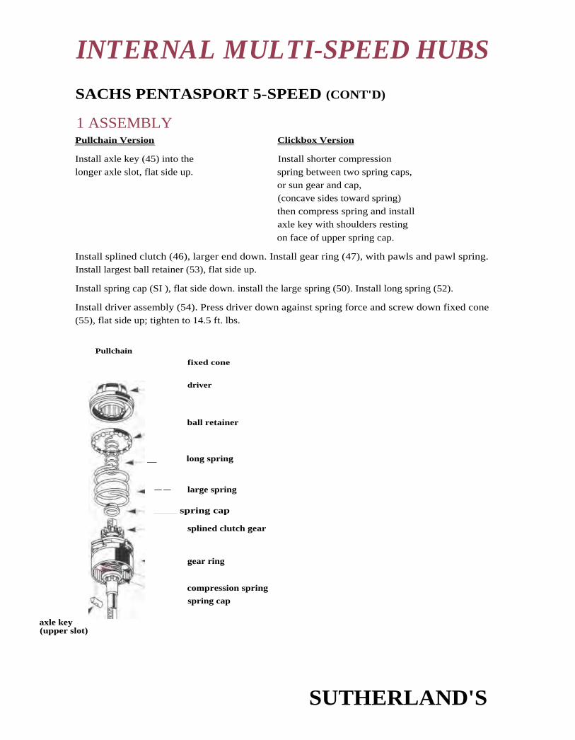
INTERNAL MULTI-SPEED HUBS
SACHS PENTASPORT 5-SPEED (CONT'D)
1 ASSEMBLYPullchain Version
Clickbox Version
Install axle key (45) into the
longer axle slot, flat side up.
Install shorter compression
spring between two spring caps,or sun gear and cap,(concave sides toward spring)
then compress spring and installaxle key with shoulders resting
on face of upper spring cap.
Install splined clutch (46), larger end down. Install gear ring (47), with pawls and pawl spring.Install largest ball retainer (53), flat side up.
Install spring cap (SI ), flat side down. install the large spring (50). Install long spring (52).
Install driver assembly (54). Press driver down against spring force and screw down fixed cone(55), flat side up; tighten to 14.5 ft. lbs.
Pullchain
fixed cone
driver
ball retainer
_ long spring
— — large spring
spring cap
splined clutch gear
gear ring
compression spring
spring cap
axle key(upper slot)
SUTHERLAND'S

- thrust washer
—spring cap
shortspring
smallsun gear
largesun gear
.4-- axle assembly
Sun gears have already
been installed. Skipthese steps.
Red Timing Aid
planetcarrier
gear ring
INTERNAL MULTI-SPEED HUBS
SACHS PENTASPORT 5-SPEED (CONT'D)
2 ASSEMBLYInvert assembly — Place axle in a vise b y its flats, long-slot
end up.
Pullchain Version Clickbox Version
If using a large sun gear withnotches all the way through(36b), you have not installedit yet. Install it now, push it
past the axle dogs and twist
it to lock it into place.
Install small sun gear (36a),
tabs downward. Install shortest
spring (28) and spring cap(42).
Install thrust washer (26).
Align planet gears with timing marks facing precisely outwardsand install planet carrier (25). Sachs parts list mentions a red tim-
ing aid (62) which aligns the gears during installation; correct
assembly is, however, possible without using this. Carrier mustengage fully over sun gears and turn smoothly. Recheck timing
marks after installation.
Caution: if planet gears are incorrectly
timed, hub will sustain damage in use.
Work planet carrier down until E-clip notch
on axle is exposed.
Install D-hole washer (24) and then install E-
clip washer (23). Planet carrier should turn
freely, with very slight lengthwise play on axle.
SUTHERLAND'S

lever coneassembly
-.14-ball retainer
INTERNAL MULTI-SPEED HUBS
SACHS PENTASPORT 5-SPEED (coNrr)
3 ASSEMBLYScrew brake cone assembly On conical side up, onto thethreads of the planet cage.
install hub shell, turning it slightly counterclockwise to
clear pawls.
Install brake shell 116), with internal tabs upwards. End of
friction spring on brake cone must engage in one of thetwo slots in lower side of the brake shoe.
Install remaining bearing retainer (15), flat side up.
Install lever cone assembly (13), turning it clockwise toengage brake shoe tabs.
Screw on the two locknuts, (5) adjust for minimal bearingplay without binding, and lock the nuts against eachother (not against lever cone assembly!) using a 17
mm cone wrench and 17 mm open-end or box-end wrench.
locknut
adjuster locknut
ro'"-4- brake shell
hub shell
brake cone
GEAR TABLE FOR INTERNALLY GEARED HUBSMultiply by gear value obtained from (..'hainwheei and rear sprocket gear charts.
Gear1
2 3 4 5 6 7
Sachs2-speed 1.00 1.363-speed 0.73 1.00 1.36
MID-speed ano .8 11.00 1.29 111-507-speed 0.59 0.67 0.81 1.0 1,24 1.48 1.69
Shimano3-speed 0.75 1.00 1.337-speed 0.63 0.74 0.84 0.99 1.14 1.33 1.55
Sturmey Archer3-speed 0.75 1.00 1,334-speed 0.67 0.79 1.00 1.275-speed 0.67 0.79 1.00 1.27 1.50
SUTHERLAND'S

H 3102 3-speedw/out brakeParts Lists: Suth
11 21 101 3 x 7hybrid system w/out brakeParts List: 189.6Itemcompat.
189
89
H 3120 3-speedwith drum brakeParts Lists: SuthItem Part no.
1 0516 OW 000la 0516 107 000
11 a
I 23
2b 0517 104 0003 0516 111 000 1,5.9
I 5
14 0574 112 10017 0576 104 200 1,6-9
Part no. compat.
00 0516 003 000 18900 0516 1 07 000 89
00 0517 107 000 1,5-9
00 0516 111 000 1,5
404 07100 4621
I 4 00 0574 114 0006 00 2376 003 000 5
Item Part no. corn pat.
1 0516 003 000 1891 a 0516 107 000 892a 0517 102 000 1
2b 051 7 104 0003 0516 111 000 1,5.94 0517 005 000 1?6?
I 15 0121 112 000 5
5 0518 113 000 56 0517 103 000 59 0577 002 000 S?13 0518 112 000 5
I 14 0508 109 000I 17 2376 403 000 5
no info no info no infono into no info nn info
24 0536 104 100 123
18 0517 002 00019 0518 103 00022h 0518 114 000
29 0572 120 100 I 29 0572 121 00120 2512 007 000 56 20 2512 007 000
not listed not listedH 0518 111 000 1,5-9
not listed not listed
not listed not listed23 0524 102 000 I 23b 0504 103 000
not listed not listed
25 0512 102 100 4,5-9 -141-4.- 25 0512 102 10030 0581 104 101 30 0581 104 101
not listed not listednot listed not listednot listed not listednot listed not listed
31 0512 115 200 31 0512 115 20032 0536 109 100 5-9 32 0536 109 100
00 0536 104 100 123 -4-
1,5-9 S 00 0517 002 100 1,5-959 9 00 0518 103 000 59
(W)1 14 00 0572 120 200
56 10 00 2512 007 000 56
not listed
not listed
not listed13 00 0504 103 000
not listed4,5-9 I 12 00 0512 115 001 .-
16 00 0581 104 101not listednot listednot listednot listed
18 00 0512 115 2005-9 17 00 0536 109 100 5-9
24 0536 104 000 123
18 0517 002 000 1,5-919 0518 103 000 59
SACHS 3-SPEED PARTS LISTNumbers listed under Item refer to the item numbers on the parts list referred to at the top of each column. Suth '92 CB book refers to Sutherland's Handbookfor coaster brakes and internally geared hubs 1992.
Hub Type H3111with coaster brakeParts Lists: Suth
Part Item Part no. compat.
1. Hex Nut 1 0516 003 000 189
1a. Cap nut la 0516 107 000 89
2. Locating washer (2 ea.) 2a 0517 102 000 I
2a. Retaining wash. (1 ea.) 2b 051 7 104 0003. tocknut (X) 3 0516 111 000 1,5-9
4. lo( kwashei
0574 110 1005. Lever cone Assy. short 8So. long 8 0574 111 100
6. Brake [ever short H 0519 014 300
7. Dust Cap li 0521 103 1008. Adjusting Nut80. Washer 10.6 x 20 x 3.38b. Adjusting washer PIP8c. Brake carrier assembly8c1. Washer 14.4 x 21 x 2.59. Adjusting Cone
0576 104 200 1,6-9W. Ball Retainer 1711. Brake Shell 1 0 0573 103 100
12 Hub Shell, 36 holes H 0501 118 00028 holes H 0501 118 001
13. Brake Cone Assembly 12 0574 106 000 1
14. Friction Spring 11 0513 102 000 378915. Pawls * 24 0536 104 100 123
16. Ring spring 25 0512 102 100 1234
17. Axle Circlip 18 0517 002 000 1,5-918. D-hole washer (thrust ) 19 0518 103 000 59
18a. Washer
0572 119 00019. Planet Carrier Assembly 29 I
20. Circlip 21 0512 104 000 I21. locating Sleeve 26 05 14 103 000
22. Planet Carrier H 0502 112 000 1
23. Thrust Washer (Z) H 0518 106 000 1,5-9 124. Pivot Pins H 0114 101 000 23
2$. Planet Gear H 0533 103 000 12326. Pawl Carrier Assembly27. Pawl Carrier
M. Ring spring I0581 104 10129. Gear Ring Assembly 30
30. Circlip H 0312 003 000
31. Dog Washer H 0518 109 OW32. Gear Ring H 0581 104 000
33. Clutch Gear H 0533 111 000
34. Ring spring 31 0512 115 20035. Pawl 32 0536 109 100 5-9

SACHS 3-SPEED PARTS LISTHub Type 113111 H 3102 3-speed H 3120 3-speed H 21 101 3 x 7
with coaster brake without brake with drum brake hybrid system w/out brake
Part Item Part no. compat. Item Part no. compat. Item Part no. compat. Item Part no. corn pat.
36. Dog Ring37. Bearing Bush
38. Gear Change Plate
39. Axle 146mm152mrn 51 330509 111 000 0509 111 000154mm159mm164mm 33 0509 112 000 33 0509 112 000 I 34 0509 114 000
00 0509 122 000168mm 15
40. Ball Cup41. Ball Retainer (7) 23 00 0576 104 200
42. Pressure Spring(large) SS 0525 104 100 35 0525 104 100 35 0525 104 100 22 00 0525 104 100
43. Pressure Spring(small) 36 0525 013 200 36 0525 013 200 36 0525 013 200 20 00 0525 013 20043a. Spoke protector 7 00 0503 003 000
0572 118 200 0572 118 000 0572 118 00044. Driver Assembly I 37 37 37 1 24 00 0572 125 0004S. Ball Retainer H 0576 102 000 123 not listed not listed 25 00 0576 102 00046. Dust Cap H 0121 108 000 123 riot listed not listed I 26 00 0521 114 00047. Fixed Cone I 39 0508 105 000 39 0508 105 000 39 0508 105 000 28 00 0508 105 000
47a. Spacer, 16.4 mm long 29 00 0534 119 10047b. Locknut (X) 44 0516 001 30048. Cap 38 0521 108 000 38 0521 108 000 38 0521 108 000 21 00 0521 108 000
49. Dust Cap (sprocket) I 40 0121 109 000 23 40 0121 109 000 23 40 0121 109 000 23 I 27 00 0521 115 00050. Spacer Washer 41 051 8 018 000 41 0518 018 000 41 0518 018 00051. Sprockets (9) 42 42 42
S la. 7-sprkt. cluster 14-32 30 69 4600 403 404
52. Cirdip 43 0512 011 000 1-9 43 0512 011 000 1-9 43 0512 011 000 1-900 0516 300 00053. Chain Guide Nut I 45 0516 1 00 102 45 0516 100 102 45 0516 100 107 I 31 6
S4. Axle Key 46 0527 100 200 46 0527 100 200 46 0527 100 200 19 00 05271C0 20055. Small Pull Rod 47 0587 102 000 789 47 0587 102 000 789 47 0587 102 000 789SSa. Long Pull Rod 32 00 0587 103 00056. Knurled Nut -at57. Adjuster Sleeve Assem. 48 0570 117 000 789 48 0570 117 000 89 48 0570 117 000 789 33 00 0570 117 000 789
Special grease A, 35g 0369 135 100
Special grease A, 2x250g 0369 135 101
COMPATIBILITY:
Duomatic 102 and 1 01
2. Automatic R 2110
3. Duomatic A 21 10
4. Ring springs of H3111 brake cone, H3102 and H3120 pawl carrier interchange
5. H 5120 Pentasport 5-speed with drum brake
6. H 5100 Pentasport 5-speed, no brake
7. Also see line 10
7. Probable but untested compatibility
H. Available as parts of newer assemblies by Sachs.
W. Part is shown in drawing but no part number is given.
X. Left locknut of 415 and 515 is compatible with right locknut of H3120 withdrum brake.
Z. May be used only in older version - check on this.
NOTE: 3 x 7 alloy shell Is rated by Sachs for tandem and offroad use.Steel shell with pressed-on flanges is not.
* #15 Pawls also used in #19 planet carrier assembly.
I Vertical lines between numbers indicates parts are not interchangeable.
ITEM - Sachs Instructions assigned parts number.Number of part in Sachs instructions
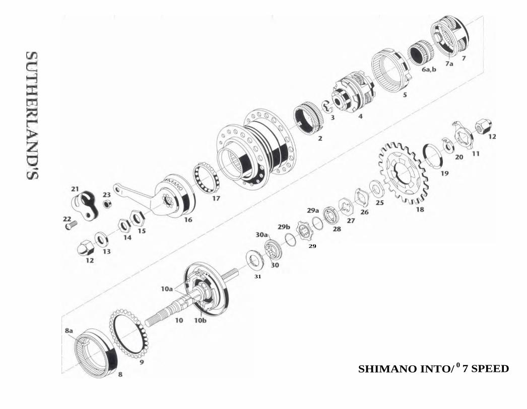
29
31
SHIMANO INTO/ 0 7 SPEED

JINTERNAL MULTI-SPEED HUBS
SHIMANO INTER*7 SPEED
How It WorksThe Shimano 7-speed hub is of very different design and construction from other internal hubgears, as is clear just from looking at the gear ratios. There is no 1-1 ratio!
This results from the Shimano huh's unusual scheme for shifting gears: a rotating sleeve (cam)on the axle which, by its angle changes relative to the axle, opens up or blocks a number of dif-ferent ratchets and pawls. This hub has four sun gears, in two compound planetary gear systems.
In all but the top two gears, drive from the sprocket is into the gear ring of the right-side plane-tary system. 11- the rightmost sun gear of this planetary system is stationary, the hub is in firstgear. if the next sun gear to the left is held stationary, the huh is in second gear. The right-sideplanetary gear system can only gear down or transfer power at unity ratio, since drive can beinput either at its planet cage or gear ring, and can not he output at its gear ring.
Gearing up is accomplished by a second planetary gear set at the left side of the huh. This is dri-ven by the planet cage of the right side gear set. For 6th and 7th gear, a set of pawls is engaged todrive the right side planet cage directly at unity ratio, while the right side gear ring freewheelsforward. The right side planet cage drives the left side planet cage, and depending on whether
the right or left sun gear of the left planet cage is engaged, the hub is in 6th or 7th gear.
The most unusual feature of the hub is that its three middle gears use both planetary gear sys-tetns, gearing down at the right side of the huh and back up at the left side. The multiplicationof ratios is comparable to that of a derailleur gearing system which uses different ratios at chain-wheels and sprockets to reach the desired final drive ratio. 3rd gear of the Shimano hub is 1st x
6th; 4th is 2nd x 6th; and 3rd is 2nd x 7th. You might ask why, if the right planetary system can
transfer power at unity ratio, the middle gear is not unity ratio. The answer: this must havesomething to do with the hidden complexities of the shifting mechanism, since in theory, drivecould be directly from the right to the left planet cage. Another possible explanation is thatdirect drive in 4th gear would reveal too clearly the hubs inefficiency in 3rd and 5th.
The 3rd and 5th gears must be achieved by using both planetary systems, since each planetarysystem has only two sets of pinions . The third and fifth gears, like the fourth, are achieved bymultiplying one of the two ratios at the right side of the hub by another at the left side.
ALIGNMENTThis hub has an overlocknut spacing of 1.30mm, a rear chainline of 48mm. The spoking flange
diameter is 87mm. The hub is available with 36 holes.
SUTHERLAND'S

INTERNAL MULTI-SPEED HUBS
TESTING SHIFTER OPERATIONThe cable may be replaced without removing the wheel from the bicycle.
Removing the Inner CableTo remove the inner cable, set shift lever to first gear position. Loosen setscrew of cassette joint.
Push the cable through the housing from the hub end, and withdraw it from the shift lever.
Replacing the Inner CableUse index-shifter certified cable and housing. The inner cable has a conventional cylindrical fer-
rule at the shift lever end, and you may replace it with a derailleur cable that has a similar ferrule.
Set the shift lever to first gear position. Pass the inner cable through the hole of the lever.
Lubricate it and pass it through the housing, then the adjuster barrel of the cassette joint.
Tighten the setscrew with a 2.5 mm Allen key while pulling lightly on the inner cable. Cut off
excess cable and cap or solder the end. Rend the end of the cable slightly toward the outside, so
it can not drag on the sprocket. Check cable adjustment, as follows:
Cable AdjustmentSet shift lever to 4th gear position. Check that red marks on cassette joint line up. If not, turn
adjusting barrel at huh end of cable. Move shift lever to first gear and back to 4th, and recheck. If
there is not sufficient adjustment range, loosen setscrew to reposition cable.
SUTHERLAND'S

INTERNAL MULTI-SPEED HUBS
SHIMANO INTER • 7 SPEED (CONTD)
Removal of Wheel from FrameRemove cable end assembly from hub only after removing wheel from frame. You may, howev-er, replace the cable itself without removing the wheel, (see "Repladng and AdjustingCable," page 16-39).
Loosen axle nuts. Slip wheel from dropout slots, taking care not to kink the shift cable. Turntab of cassette joint fixing ring 45 degrees counterclockwise. Cassette joint and fixing ring maynow be lifted over axle nut and tab washer, and you may remove the drive chain past the rightend of the axle.
Assembly of Wheel to FrameInstall sprocket and clip ring to hub driver.
Install shift cable assembly to hub as follows, before installing wheel in frame.
If the drive chain has not been disconnected, place it over the sprocket now. Set shift lever to I.
Make sure cable housing is seated in ferrules at both ends. Rotate pulley at hub end of cable
clockwise with yellow marks facing upwards until they line up. Then align them over yellowmarks at right end of hub. Position cassette joint fixing ring also with yellow marks aligned,press it down and rotate it 45 degrees clockwise to lock.
Check operation of shift lever. If there is a yellow pin in cassette joint which prevents shift pul-ley from turning, remove the pin.
Check that red marks on cassette joint line up with shift lever in 4th gear position. If not, (see"Replacing and Adjusting Cable," page 16-39).
Position the shift cable on the frame and insert the hub into the rear fork.
Align the cassette joint nearly parallel to the chainstay and install the non-turn washer on the
right end of the hub axle, with the tab projecting into the drop-out slot, facing toward the outerend of the slot. The flats of the axle and of the non-turn washer are not parallel to the drop-outslot. Black non-turn washer is for forward-facing slot and gold washer is for rear-facing (track-
type) slot. Install a serrated washer without tab on the left end of the axle.
Install axle nuts, adjust chain slack and secure nuts. Secure the brake arm to the frame with thebrake arm clip. Multi-hole strap must he cinched tightly around chainstay, not looped looselyover it.
Adjust position of cable on frame, and secure it with cable bands.
SUTHERLAND'S

INTERNAL MULTI-SPEED HUBS,
Troubleshooting Chart Shimano Inter-0 7 SpeedSYMPTOMS Resulting from wear, improper
lubrication or abuseResulting from improperassembly or installation
3. Carrier (4) covers or partly_covers E-clip groove of axle.n,_
1. Brake grabs or squeals.
2. Stiff running, noisy.
4. Hub jams in oneor more gears.
5. Hub will not shift toall gears (cable slack inlower gear; or lever willnot move to higher gear).
6. Jumps to next higheror lower gear.
7. Slips in 1st and 2nd.
8. Slips in 1st and 3rd.
10. 1st instead of 2nd;3rd instead of 4th.
11. 1st instead of 3rd; 2nd insteadof 4th and 5th; "3rd" (unityratio) instead of 6th and 7th.
Incorrect or insufficient internallubrication.
Brake arm forcing brake cone outof line.One pawl of a pair faulty.Dropouts not parallel.Chain too light.Cones too tight.Bent dustcap.Broken or chipped gear teeth.Ball retainer damaged or broken.
Axle bent.
Pawls inside sun gear (4, 6a 6b)or in driver jammed.Broken or displaced parts inside hub.
Axle sleeve bent, worn or chipped.
Helical springs inside driver weakor damaged.
Cable frayed, kinked or unlubricated.
External pawls of planet carrier (4)do not engage.
Axle pawls (10b) engaging sun gear,(7a) (tiny pawls!) do not engage.
Pawls of sun gear (6a) retractedor damaged.
Narrower teeth of pinions in planetcarrier (7) stripped.
Sun gear (6a) stripped.
Pawls of gear ring (6b) retractedor damaged.
Brake arm loose at frame.
Ball retainer (17) (left side)installed upside down.Friction spring of gear ring (5)reversed.One pawl of a pair improperly installed.E-clip missing.
Ball retainer H (right side) installedflat side down.Friction spring of ring gear unit 1improperly seated.Sun gear 2 and 3 assembly inverted.Gears or pawls not properly seated.
Cable too tight or loose.
Cassette joint assembly incorrectlyinstalled.
Forced assembly has displaced axlepawls engaging sun gear 1. Theyshould point counterclockwise,looking from left end of axle.Driver pawls that should engage
9. Slips, and brake release is gear ring (8) retracted or damaged
erratic, in 1st through 5th.
SUTHERLAND'S

INTERNAL MULTI-SPEED HUBS
Troubleshooting Chart - Shimano inter s 7 SpeedSYMPTOMS Resulting from wear, improper Resulting from improper
lubrication or abuse assembly or installation
12. 4th instead of 5th;6th instead of 7th.
Pawls of sun gear 3 retracted ordamaged.
13. 2nd instead of 6th; "4th"(1st x 7th) instead of 7th.
Forward-driving pawls of driver whichshould engage ratchet at right end ofplanet carrier (7) are damaged, orremain retracted in 6th and 7th.
14.1st instead of 3rd; 2nd Pawls of sun gear 4 (in planet carrierinstead of 4th; "4th" assembly 4) retracted or damaged.(unity ratio) instead of 6th.
------n Sun gear (4a) (in planet carrier assem-bly 4) stripped.
Narrower teeth of pinions in planetcarrier (4) stripped.
15. Hub occasionally jumpsforward when power isapplied in 3rd through 7th.
16. Excessive pedal travelbefore brake engages.
17. No brake.
_ Pawl retractor sleeve of gear ring (5)damaged.
Brake shoe or hub shell glazed orworn.
Wrong lubricant.
Friction spring of gear ring (8) weak.
Rollers of roller clutch of planetcarrier (4) do not turn freely.
Pawl retractor sleeve of gearring (5) missing.
Friction spring of gear ring(8) absent.
Friction spring of planet carrier(4) weak.
Friction spring of planet carrier(4) absent.
Reverse (clockwise, seen fromleft end of axle) pawls of driverdamaged or retracted.
18. Brake does not release orreleases erratically in 3rdthrough 7th.
SUTHERLAND'S

INTERNAL MULTI-SPEED HUBS
PARTS LIST FOR SHIMANO INTER•7-SPEEDWITH COASTER BRAKE SG-7C21
1 33Z 9801 Internal Assembly (axle length 169.5 mm)
2 330 9801 Brake shoe
3 325 3200 E-Clip (9 mm diameter)
4 330 9804 Planet carrier assembly - unit 2
5 330 9802 Gear ring - unit 2
6a,b 330 9803 Sun gear assembly
7 330 9806 Planet carrier - unit 1
7a Sun gear
8 330 9805 Gear ring - unit 1
8a Friction spring
9 330 9807 Ball retainer H (3/16 )
10 330 9808 Driver and axle (axle length 169.5 mm)
10a C Pawls
10b Axle Pawls
11 33Z 9802 Cassette joint fixing ring
12 314 1400 Cap nut (9.5mm thread)
13 220 0601 Washer (3.2 mm thick)
14 321 3801 Lock nut (3.5 mm thick)
15 335 4810 Stop nut
16 330 9810 Brake arm
17 330 9811 Ball retainer B (3/16 balls)
18 Sprockets1
19 321 2000 Snap ringl
20 337 2010 Non-turn washer 1 (black)
33Z 2020 Non-turn washer 2 (gold)
21 330 9812 Brake arm clip, 16 mm (5/8 )
330 9813 Brake arm clip, 19 mm (3/4) )
22 333 0702 Clip screw
23 282 2903 Clip nut
24 1 30 9890 TL-7520 Hub spanner (cone wrenches) (17mm x 22mm) 2 pcs.
25 321-3801 Locknut
26 "UM27
Four-flat washe
Cam washer
28 Plated plastic washer
29 Eight-tab washer
29a,b Wire ring
30 Axle cone
Plastic seal30a
31 Bearing retainer
L2 6 – 31 not available from Shimano seQara t
1 (See Sutherlatuts Hatulhook of Coaster Brakes & Internally Geared Hubs pages 1-3.)
SUTHERLAND'S

Ag''r : INTERNAL MULTI-SPEED HUBS
PARTS LIST FOR SHIMANO INTER•7-SPEEDWITH COASTER BRAKE SG-7C21 (coN-rD)
RAPIDFIRE LEVER ST-7S20 FOR 7-SPEED
1 61W 9804 R.H. shift lever unit
2 61W 9801 Bracket fixing screw (MS x 18) and nut
3 61W 9802 Lever fixing bolt (M5 x 1 3) and spring washer
4 61W 9803 Cable adjusting barrel unit
5 749 9804 Cassette joint unit for SG-7C21
749 9803 Cassette joint unit for SG-7C20
6 749 9802 Cable adjusting barrel and spring for cassette joint
7 33Z 9802 Cassette joint fixing ring for SG-7C21
[also 411 1 in parts list for hub]
749 1200 Cassette joint fixing ring for SG-7C20
8 600 9851 Inner cable box (Stainless/100 pcs.)
9 60B 1385-1 SIS-SP outer casing (1380mm/black)
60B 1485-1 SIS-SP outer casing (1480mm/black)
60B 1565-1 SIS-SP outer casing (1560mm/black)
60B 1705-1 SIS-SP outer casing (1 700mm/black)
10 620 9803 Inner end cap (1.2 mm diameter/100 pcs.)
SUTHERLAND'S
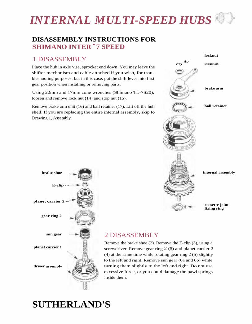
brake shoe -
E-clip - -
planet carrier 2 --
gear ring 2
sun gear
planet carrier 1
driver assembly
locknut
C) At-
stopnut
brake arm
ball retainer
internal assembly
cassette jointfixing ring
INTERNAL MULTI-SPEED HUBS
DISASSEMBLY INSTRUCTIONS FORSHIMANO INTER • 7 SPEED
1 DISASSEMBLYPlace the hub in axle vise, sprocket end down. You may leave the
shifter mechanism and cable attached if you wish, for trou-bleshooting purposes: but in this case, put the shift lever into first
gear position when installing or removing parts.
Using 22mm and 17mm cone wrenches (Shimano TL-7S20),
loosen and remove lock nut (14) and stop nut (15).
Remove brake arm unit (16) and ball retainer (17). Lift off the huhshell. If you are replacing the entire internal assembly, skip to
Drawing 1, Assembly.
2 DISASSEMBLYRemove the brake shoe (2). Remove the E-clip (3), using a
screwdriver. Remove gear ring 2 (5) and planet carrier 2
(4) at the same time while rotating gear ring 2 (5) slightly
to the left and right. Remove sun gear (6a and 6b) whileturning them slightly to the left and right. Do not use
excessive force, or you could damage the pawl springs
inside them.
SUTHERLAND'S

planet - --carrier 1
gear ring 1
frictionspring
locknut
tabbedfour flat
washer
cam washer
— - platedplastic washer
------ wire ring
------ six tabwasher
- wire ring
fixed cone
bearingretainer
C
O
+IF'601-1
INTERNAL MULTI-SPEED HUBS
ball retainer
SHIMANO INTER • 7 SPEED (CONT'D)
3 DISASSEMBLYRemove planet carrier 1 7). Remove guar ring 1 {8) while turning it slight-ly to the left and right. Remove axle from vise and invert. Shake loose andremove ball retainer (9) while depressing pawls C of the driver and axleunit. Be careful not to bend ball retainer (9).
AXLE DRIVER DISASSEMBLYShimano does not recommend the drive side of the hub be disassem-
bled. The parts are not available.
While Shimano does not give instructions to disas-
semble the axle from the driver, it is necessary to dothis, to check, clean and relubricate the hearingbetween the driver and axle. The disassembly andreassembl y pose no unusual problems if care is taken
not to lose any of the parts — they can not bereplaced individually! Be careful not only of the coneand other axle-end parts, but also of the small pawls
just inboard of the driver.
Insert the axle assembly in a vise with soft jaws justinboard of the left-end threads, driver end up.
Loosen the right-side locknut (25) with a 1.7minwrench while holding the axle flats with a thick 8minwrench or adjustable wrench. Do not use a wrench
on any part under the locknut. All of these parts
are tabbed rather than threaded, and you could damage the tabs.
Lift off tabbed four-flat washer (26). Remove cam washer (27) by lilting itoff the axle. Carefully remove plated plastic washer (28) by lining it off theaxle without losing the small wire ring (29a) under it. Remove the smallwire ring from the top of the six-tab washer on the axle or from the under-side of the plated plastic washer which you have just removed.
Lift six-tab washer (29) oft the axle. Re careful not to lose the small wire ring129b) under it. Remove small wire ring from groove in top of fixed cone onthe axle or f rom underside of six-tab washer which you have just removed.
Remove fixed cone (30) by sliding or prying it upward off the notches of theaxle. Remove flexible, plastic seal (30a1 from groove of fixed cone. Removebearing retainer (31). Remove the driver assembly from the axle assembly.
SUTHERLAND'S

INTERNAL MULTI-SPEED HUBS
SHIMANO INTER • 7 SPEED (CONT'D)
CleaningClean all parts, including outside of huh shell, in a suitable solvent. Be very careful not to intro-
duce dirt or grit after cleaning. If you have not disassembled the axle from the driver, do not
clean the driver end of the axle-driver assembly, as you will be unable to relubricate it properly
and may introduce dirt which you can not remove.
Points to Check1. Pawls: 4 sets in driver/axle assembly (10); 2 sets in sun gear (6); 1 set in gear ring (5); 2 sets in
carrier( 4) — for chipped or rounded edges and for misalignment.
2. Pawl springs: 4 in driver/axle assembly (10); 2 sets in sun gear (6); 1 in gear ring (5); 2 sets in
carrier (4) for shape and tension.
3. Ratchets: 2 in hub shell; 3 on axle (10); 1 inside gear ring (8); 2 inside and outside right end
of carrier (7) for chipped or rounded edges.
4. Gear teeth of sun gear 6a and 6b; of sun and planet pinions of carrier (7) and carrier (4); of
gear ring (8) and gear ring (5) — for wear and chipping.
5. 2 concentric helical shift sleeve return springs of axle (10); friction spring of gear ring (8);
pawl retractor spring on outside of gear ring; ring spring of brake shoe assembly (2) for shape
and tension.
6. Driver (10), brake cone (11) and hub shell bearing races for wear and pitting. Note: there is a
concealed bearing between axle and driver. Unless you have disassembled it, test it by rotat-
ing it to feel for roughness.
7. Dustcaps, ball retainers (9), (17), E-clip (3) and axle (10) for straightness.
8. All threaded parts for damaged or stripped threads.
9. Brake shoes (2) and hub shell for wear or glazing.
LubricationLubricate pinion pins by dripping a few drops of oil on their exposed ends. Lubricate pawl
springs lightly with oil. Lubricate shifter springs, pawls and sleeve of axle-driver assembly
lightly with oil. Use a good cycle oil. WD-40 is too light for lasting lubrication. 3-in-1 oil
gums up with age.
Lubricate ball retainers by filling the spaces between the balls with grease. Lubricate hub shell,
brake shoes (inside and out), axle assembly and pinion teeth liberally with grease: use Shimano
7-speed hub grease, part no. 041 3011.
SUTHERLAND'S
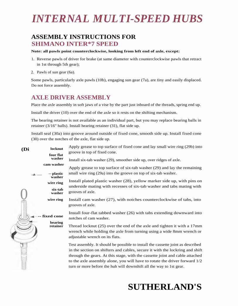
(Di locknut
four flatwasher
cam washer
-4- —
0
— plasticwasher
wire ring
six-tabwasher
wire ring
-- fixed cone
bearingretainer
INTERNAL MULTI-SPEED HUBS
ASSEMBLY INSTRUCTIONS FORSHIMANO INTER*7 SPEEDNote: all pawls point counterclockwise, looking from left end of axle, except:
1. Reverse pawls of driver for brake (at same diameter with counterclockwise pawls that retractin 1st through 5th gear);
2. Pawls of sun gear (6a).
Some pawls, particularly axle pawls (10b), engaging sun gear (7a), are tiny and easily displaced.Do not force assembly.
AXLE DRIVER ASSEMBLYPlace the axle assembly in soft jaws of a vise by the part just inboard of the threads, spring end up.
Install the driver (10) over the end of the axle so it rests on the shifting mechanism.
The bearing retainer is not available as an individual part, but you may replace bearing balls in
retainer (3/16" balls). Install hearing retainer (31), flat side up.
Install seal (30a) into groove around outside of fixed cone, smooth side up. Install fixed cone
(30) over the notches of the axle, flat side up.
Apply grease to top surface of fixed cone and lay small wire ring (29b) into
groove in top of fixed cone.
Install six-tab washer (29), smoother side up, over ridges of axle.
Apply grease to top surface of six-tab washer (29) and lay the remainingsmall wire ring (29a) into the groove on top of six-tab washer.
Install plated plastic washer (28), yellow marker side up, with pins on
underside mating with recesses of six-tab washer and tabs mating with
grooves of axle.
Install cam washer (27), with notches counterclockwise of tabs, intogrooves of axle.
Install four-flat tabbed washer (26) with tabs extending downward intonotches of cam washer.
Thread locknut (25) over the end of the axle and tighten it with a 17mm
wrench while holding the axle from turning using a wide 8mm wrench oradjustable wrench on its flats.
Test assembly. It should be possible to install the cassette joint as describedin the section on shifters and cables, secure it with the lockring and shift
through the gears. At this stage, with the cassette joint and cable attachedto the axle assembly alone, you will have to rotate the driver forward 1/2turn or more before the huh will downshift all the way to 1st gear.
SUTHERLAND'S

sun gear 6a, b
planet carrier 1
driver assembly
INTERNAL MULTI-SPEED HUBS
SHIMANO INTER • 7 SPEED (CONT'D)
3 ASSEMBLY planet
carrier 1
Insert the axle-driver assembly into a vise, sprocket end down. If assem-
bling with the shift lever and cable attached for troubleshooting purposes,
place the shift lever in first gear position. Otherwise, you will not be able to
seat some of the assemblies, and you may force some pawls out of position.
install ball retainer (9) flat side up over one pawl (10a) of axle driver
assembly (10). Then depress the other pawl (10a) with the tip of a screw-
driver and pass ball retainer (9) into position beyond it. Be careful riot to
bend ball retainer (9).
gear ring 1
frictionspring
ball retainer
Insert the end of friction spring (8a) of gear ring I into the wide hole D
of the driver ; depress pawls (10a) and install gear ring 1 (8). Face of gear pawl
ring should rest flat against ball retainer (9). Turn gear ring counterclock- axle andwise against resistance of friction spring (8a); pawls should click. driver
assembly -----Install planet carrier 1 (7), small end down. Be especially careful that
hub is in 1st gear (or cable is disconnected), and do not force assembly,
as the tiny axle pawls (10b) which engage sun gear (7a) in this unit are
easily dislodged. Turn planet carrier 1 (7) slightly back and forth to
engage teeth of pinions with teeth of gear ring 1 (8). After installation,
rotate planet carrier 1 (7) forward (counterclockwise) and check that
both of the axle pawls (10b) inside sun gear (7a) are ratcheting correctly.
driver
2 ASSEMBLYInstall sun gear (6a,b) to mesh with planet pinions of carrier
(7). Sun gear (6a), which is one piece with smooth mid-
dle ring of unit, must be at top. Work the unit into place
by carefully rotating left and right. Do not use force, as this
could damage the pawls.
Place gear ring 2 (5) over planet carrier 1 (7), with the gear
ring teeth facing upward.
Install planet carrier 2 (4), turning the carrier unit slightly to
the right and left to engage the teeth of the planet pinions
in gear ring 2 (5).
Push down planet carrier 2 (4), and check that the full width
of the circlip groove of the axle is visible over the upper edge
of planet carrier 2 (4). While pushing down on planet carrier
2, insert the E-clip (3) into the hub axle groove.
SUTHERLAND'S

ball retainer
brake shoe
internal assembly
INTERNAL MULTI-SPEED HUBS
SHIMANO INTER • 7 SPEED (CONT'D)
1 ASSEMBLYExpand the brake shoe (2) over the roller clutch of planet carrier 2 (4) four-notch side up, align-
ing the notched Section between the two brake shoes with the end of the friction spring of plan-
et carrier 2 (4).
Slip the hub shell over the assembly, turning it slightly to the left and right so that the sealing
spring of the hub shell is positioned in the right hand dust cap of the internal assembly. Turn
the hub shell counterclockwise to check that it turns smoothly.
Reinstall hall retainer (17), flat side up. Reinstall brake arm (16), turning it to the right and left
until the notches of the brake shoe engage with the tabs of the brake arm unit.
Reinstall the larger nut (15), flange down, and the smaller nut (14). Adjust bearings so hub shell
can he turned freely, but without bearing play, and tighten nuts against each other using 22 rum
and 17 mm cone wrenches.
SUTHERLAND'S

INTERNAL MULTI-SPEED HUBS
SHIMANO INTER • 7 SPEED (coNTD)GEAR TABLE FOR INTERNALLY GEARED HUBSMultiply by gear value obtained from chainwheel and rear sprocket gear charts.
Gear 1 2
Sachs2-speed 1.00 1.363-speed 0.73 1.00 1.365-speed 0.50 0.78 1.00 1.29 1.57-speed 0.59 0.67 .81 1.0 1.24 1.48 1.69
Shimano3-speed 0.75 1.00 1.33
p7-speed IIIIM0.63 J 0.74 .10.84 III 0.99 a 1 1.14 11.33 0.55.41
Sturmey Archer3-speed4-speed5-speed
0.750.670.67
1.000.790.79
1.331.001.00
1.271.27 1.50
SUTHERLAND'S

INTERNAL MULTI-SPEED HUBS
SUTHERLAND'S

A
CONTENTS
17AP
APPENDIX
AppendixMarkings and abbreviations .....2
ISO Standards ................... 2-5
Safety Standards .............. 5
Wire Gauge Chart ........... 6
Tap Drill Sizes .................... 6
Weight Conversions ........ 7
Millimeters to Inches ...... 8-9
Bicycle Parts Guide .......... 1 0-11
Spoke Length Formula 12
Trail Formula ...................... 12
Gear Ratio Formulas ........ 1 2
Thread Standards ............. 1 2
Torque Ratings .................. 1 3
Recommended Books 14
Gear Charts ........................ 15-24
SUTHERLAND'S

* APPENDIXMARKINGS AND ABBREVIATIONS
Where Used
A British Standard Cycle French parts
B British
BSC British Standard Cycle
D Right-handed threads French parts
F Thread Italian parts
FF French threads Italian parts
Fl English threads Italian parts
Left-handed threads French parts
Left-handed threads Spanish parts
JIS Japan Industrial Standard
Left-handed threads English parts
LH Left-hand
M Metric
OEM Original Equipment Manufacturer
R Right-handed threads English parts
RH Right-hand
S Left-handed threads Italian parts
TPI Threads per inch
I NTERNATIONAL STANDARDS ORGANIZATION STANDARDSThe following standards for bicycles have been approved:
ISO No. Title and Description of Standard Comments
DIS 4881 Spoke Diameter and Threads
1.8nun SO
2.0mm 56 TP1J
2.3mm 56 TPI
2.6mm 56 TPI
Compatible with existing U.S.
and British spokes and nipples.
DIS 6692 Marking of Components for Identification of Threading
Metric* British*
M 34.7 x I B 1.375 x 24 Where there is ample space.
M 34.7 B 1.375 Less space.
M B Very little space.
DIS 6693 Cottered Crank and Axle Attachment
Axle diameter I onim
Flat for cotter
Depth 3mtu
Width 8iiiiit
(cont'd.)
* (See pages 0-2 and 0-3 for an explanation of thread designation and measure.)
SUTHERLAND'S

DIS 6694 Pedal to Crank Thread
Primary standard (left pedal left-threaded1
Threading B .500 x 20
thread length 12.5mm + 0.5 0
[bread angle 60' ISO
Alternate standard (left pedal left threaded)
Threading B .562 x 20
Thread length 12.5mm + 0.S — 0
1 0mm + 0.5 — 0
Thread angle 60" ISO
DIS 6695 Cotterless Crank (Square-End) Fitting
Included-taper angle 4 ± 10 minutest
Length of flatRight 18111111 +0.5 — 0
Left 16mm +0.5 — 0
Dimension across 12.6mm +.02 — .05
Hat 1.5mm from endSpindle end to bolt seat
Loose 3min
Tightened 1.5mm min.
Crank-fixing threadsBolt-type M 8x 1
Nut-type M 10 x 1.25
Crank holt or nut size 14nunDustcap threads M 22x]
APPENDIX *ISO STANDARDS (CONTD)ISO No. Title and Description of Standard Comments
DIS 6693 Cottered Crank and Axle Attachment (cont'd)Cotter pin
Diameter 9.5mm (.374")
Length 43mm
Taper
Thread M 7 x 1
ISO cotter interchanges with
British 3/8"1.375"). All othercommon sizes are smaller;
cranks can be drilled out to
standard size.
Smaller diameter was chosen
for compatibility with 1-piececranks.
Compatible with British.For aluminum cranks.For steel cranks.
Taper angle is compatible with
most cranks. Spindle flats are long
enough at inside for all cranks,but spindle may protrude into
extractor hole of a few cranks.Grind axle end if necessary.
Same as existing spindles.
Fits all except CampagnoloSuper Record.
Fits all except TA, pre-1982
Stronglight.
DIS 6696 Bottom Bracket Threads
Left side B 1.375 x 24 Compatible with British.
Right side B 1.375 x 24 I.
t 2' on each side.
* See pages 0-2 and 0-3 for an explanation of thread designation and measure.
SUTHERLAND'S

* APPENDIX150 STANDARDS (coNro)ISO No. Title and Description of Standard
D15 6697 Hub Axle ThreadingSolid
Front M 8 x 1Rear M 9 x 1
Hollow
Front(and BMX solid) M 9 x 1Rear M 10 x 1
Comments
Compatible with French.No current compatibility.
Compatible with French.Compatible with many brandsbut not Campagnolo; Zeus:lOrnm x 26 TP1.
Hub Width Between Drop Outs
Width Space Front (±1) (+1 - 0)
Primary Standard 1(X)Secondary Standard 91
Rear
Single freewheel, 110 21coaster hub
3-, 4-speed 117 28freewheel, geared hub
4-, 5-speed 122 345-, 7-speed 126 36Freewheel Threads
Threading B 1.375 x 24
Thread angle 60° ISOlength of thread
Freewheel 10min min.Hub lOrnm
Seatpost Clamp Bolt M 8 x 1
Brake Bolt Hole 6.2mmHandlebar Diameter 25.4mm +0 - .020mmThreading of Fork and Headset
HeadsetTP1 24Major diameter 25.522mmPitch diameter 24.836mmMinor diameter 24.379 m m
DIS 6698
DIS 6699
DIS 6700
Compatible with British andItalian: thread diameter is
intermediate. Thread form
slightly different.
Compatible with British, Italian.
SUTHERLAND'S

APPENDIX *ISO STANDARDS (CONTD)ISO No. Title and Description of Standard Comments
DIS 6700 Threading of Fork and Headset (cont'd)
Fork Min. Max.
Major diameter 25.316mm 25.496mm
Pitch diameter 24.685mm 24.810mm
Minor diameter 24.209mm
Thread Form ISO 965/1 (60' modified to
H/6 truncation at root)
DIS 6701 Exterior Dimensions of Spoke Nipples
Spoke Wrench Nipple Nipple Rim To compare other standards,
diameter flat shank head hole (see chart on page 11-5).1.8mm 3.3 4.0 6.0 5.0
2.0mm 3.3 4.0 6.0 5.0
2.3mm 3.8 4.8 6.5 5.5
2.6mm 4.5 5.5 7.5 6.5
Safety StandardsISO 42101 The ISO has established tests for manufacturing quality assurance related to safety
and integrity. Bicycles identified as meeting ISO 4210 conform to these standards.
Lighting and Reflectorization Standards ISO 6742ISO 6742
ISO 6742 refers to lighting and rellectorization. Equipment bearing ISO 6742
markings conform to these standards. In particular, ISO standards for generatorand battery lights are considerable higher than pre-existing national standards.
SUTHERLAND'S

* APPENDIXWIRE GAUGE COMPARISON CHART
EnglishGaugeNo.
BritishWire Gaugemm
Standard(SWG)inches
French WireGauge No.(Jauge de Paris) mm inches
27 0.41 0.016 P 0.5 .020
26 0.46 0.018 1 0.6 .024
25 0.51 0.020 2 0.7 0.28
24 0.56 0.022 3 0.8 .031
23 0.61 0.024 4 0.9 .035
22 0.71 0.028 5 1.0 .039
21 0.81 0.032 6 1.1 .043
20 0.91 0.036 7 1.2 .047
19 1.02 0.040 8 1.3 .051
18 1.22 0.048 9 1.4 .05517 1.42 0.056 10 1.5 .059
1 6 1.63 0.064 11 1.6 .063
15 1.83 0.072 12 1.8 .07114 2.03 0.080 13 2.0 .079
13 2.34 0.092 14 2.2 .08712 2.64 0.104 15 2.4 .095
11 2.95 0.116 16 2.7 .106
10 _i_ 3.25 [ 0.128 17 3.0 .118
Spoke SizesNote the underlined sizes in the chart above. they are a source of a lot of confusion. English gauge
numbers get smaller as wire gets larger. French gauge numbers get larger as wire gets larger.
'The gauge numbers cross about where cycle spokes are.
TAP DRILL SIZES
Metrics SizesThread Size Nearest US Tap Drill Size Metric Tap Drill Size
5.0mm x 0.8mm #19 4.20mm
6.0mm x 1.0mm #9 5mm
10mm x 1.0mm 9mm
American SizesThread Size US Tap Drill Size
6-32 #368-32 #2910-32 #2110-24 #251/4-20 #7
SUTHERLAND'S

Pounds ounces Grams
1000nMI
.4.111n
2 lbs. --‘-- 900
...n0. '
••=1
1 lbs. 12 oz. 800
.•n
I•1n1
—s— 7001 lbs. 8 oz.
—.--
_/— 600
1113s. 4 oz.
--\— 500MOM
1 lbs.
n1
--J-- 400
nI
12 oz.
nIl
3001n1
."niln
8 oz.
200
nI
—/--
4 oz.100
''SInn
ilnI
o 0
Pounds Kilograms
50/-'
nM.
n
20
40
—1--
.nI
-/—in,
nMI
nIl
15.nI
—1—
30.....n•n
n
..IM=
—\--
—__/— 10
20
10
171
'.,.w.
ni
—1—
•n,
nI
...mn• 5
—\—nIl
0 0
APPENDIX * WEIGHT CONVERSIONS
SUTHERLAND'S

* APPENDIXCONVERSION CHART
Millimeters to Inches
1 mm = 0.0394 inches
1 inch = 25.4 millimeters
Milli
meterDec.
Equiv.Frac-tional meter
Dec.Equiv.
Frac,tional meter
Dec.Equiv.
Frac-tional
.1 .0039 3.18 .1250 1/8 6.35 .2500 1/4
.2 .0079 3.2 .1260 6,4 .2520
.25 .0098 3.25 .1279 6.5 .2559
.3 .0118 3.3 .1299 6.6 .2598
.39 .0156 1/64 3.4 .1338 6.7 .2638
.4 .0157 3.5 .1378 6.75 .2656 77/64
.5 .0197 3,57 .1406 9/64 6.8 .2677
.6 .0236 3.6 .1417 6.9 .2716
.7 .0275 3.7 .1457 7.0 .2756
.75 .0295 3.75 .1476 7.1 .2795
.79 .0312 1/32 3.8 .1496 7.14 .2812 9/32
.8 .0315 3.9 .1535 7.2 .2835
.9 .0354 3.97 .1562 5/32 7.25 .28541.0 .0394 4,0 .1575 7.3 .28741.1 .0433 4,1 .1614 7.4 .29131.19 .0469 3/64 4.2 .1654 7.5 .29531.2 .0472 4.25 .1673 7.54 .2969 19/641.25 .0492 4.3 .1693 7.6 .29921.3 .0512 4.37 .1719 11/64 7.7 .30311.4 .0551 4.4 .1732 7.75 .30511.5 .0591 4.5 .1772 7.8 .30711.59 .0625 1/16 4.6 .1811 7.9 .31101.6 .0630 4.7 .1850 7.94 .3125 5/161.7 .0669 4.75 .1870 8.0 .31501.75 .0689 4.76 .1875 3/16 8.1 .31891.8 ,0709 4.8 .1890 8.2 .32281.9 .0748 4.9 .1929 8.25 .32481.98 .0781 5/64 5.0 .1968 8.3 .32682.0 .0787 5.1 .2008 8.33 .3281 21/642.1 .0827 5.16 .2031 1 3/64 8.4 .33072.2 .0866 5.2 .2047 8.5 .33462.25 .0886 5.25 .2067 8.6 .33862.3 .0905 5.3 .2087 8.7 .34252.38 .0937 3/32 5,4 .2126 8.73 .3437 11/322.4 .0945 5.5 .2165 8.75 .34452.5 .0984 5.56 .2187 7/32 8.8 .34652.6 .1024 5.6 .2205 8.9 .35042.7 .1063 5.7 .2244 9.0 .35432.75 .1083 5.75 .2264 9.1 .35832.78 .1094 7/64 5.8 .22832.8 .1102 5.9 .23232.9 .1142 5.95 .2344 1 5/643.0 .1181 6.0 .23623.1 .1220 6.1 .2401
6.2 .24416.25 .24616.3 .2480
SUTHERLAND'S

meterDec.
Equiv.F rac-tional
Millimeter
9.13 .3594 23/64 15.889,2 .3622 1 6.09.25 .3641 1 6,279.3 .3661 1 6.59.4 .3701 1 6,679.5 .3740 17.09,53 .3750 3/8 17.069.6 .3780 17.469.7 .3819 17,59.75 .3838 17.869.8 .3858 1 8,09.9 .3898 1 8.269.92 .3906 25/64 1 8.5
1 0.0 .3937 1 8.651 0.32 ,4062 1 3/32 19.01 0.5 .4134 19,051 0,72 .4219 27/64 1 9.4511.0 .4330 19.511.11 .4375 7/16 1 9.8411.5 .4528 20,011.51 .4531 29/64 20.2411.9 .4687 1 5/32 20.512.0 .4724 20.641 2.30 .4843 31/64 21.01 2.5 .4921 21.031 2.7 .5000 1/2 21,151 3.0 .5118 21.431 3.10 .5156 33/64 21.51 3.49 .5312 17/32 21.61 3.5 .5315 21.71 3.89 .5469 35/64 21.831 4,0 .5512 21.8514.29 .5625 9/16 21.914.5 .5709 22.014.68 .5781 37/64 22.231 5.0 .5906 22.51 5.08 .5937 1 9/32 22.621 5.48 .6094 39/64 23.01 5.5 .6102 23.02
23.4223.5
APPENDIX *
Dec.Equiv.
F rac-tional
Milli-meter
Dec.Equiv.
F rac-tional
.6250 5/8 23,81 .9375 1 5/16
.6299 24.0 .9449
.6406 41/64 24.21 .9531 61/64
.6496 24.5 .9646
.6562 21/32 24.6 .9687 31/32
.6693 25.0 .9843
.6719 43/64 25.0 .9844 63/64
.6875 11/16 25.4 1.0000 1
.6890 25.6 1.0079
.7031 45/64 25.8 1.0157 1.1/64
.7087 26 1.0236
.7187 23/32 26.19 1.0312 1-1/32
.7283 26.2 1.0315
.7344 47/64 26.4 1.0394
.7480 26,5 1,0433
.7500 3/4 26.59 1.0469 1-3/64
.7656 49/64 26.6 1,0472
.7677 26.8 1.0551
.7812 25/32 26.99 1.0625 1-1/16
.7874 27 1.0629
.7969 51/64 27.2 1.0708
.8071 27.38 1.0781 1-5/64
.8125 13/16 27.4 1.0787
.8268 27.78 1.0937 1-3/32
.8281 53/64 28.18 1.1094 1-7/64
.8327 28_58 1.1250 1-1/8
.8437 27/32 28.97 1.1406 1-9/64
.8465 29.37 1.1562 1-5/32
.8504 29.77 1.1719 1-11/64
.8543 30.16 1.1875 1-3/16
.8594 55/64 30.2 1 1889
.8602 30.56 1.2031 1-13/64
.8622 30.95 1.2187 1-7/32
.8661 31.35 1.2344 1.15/64
.8750 7/8 31.75 1.250 1-1/4
.8858 32 1.2598
.8906 57/64 34.7 1.3661
.9055 34.92 1.3750 1-3/8
.9062 29/32 35 1.3779
.9219 59/64 36 1.4173
.9252
For larger numbers, movedecimals to the right:e.g., 220 mut = 8.661 inches
SUTHERLAND'S

freewheel or bloaik--roue libreruota liberaFreilaufrueda libre7 1
1 —7t
rear derailleur (GB-rear changer)derailleur arrierecambiohinterer Umwerfercambia de marchas.1kk401
chainstaysbasestubi posteriore orizzontaleuntere Hinterradgabelhorquilla inferior crank
rranimanoveliaTretkurbel
chainchainecatenaKeftecadena
seat post (GB-seat pin, seat pillar)tige de sellecannotto reggisellaSattelstutzetija del sillin
1- Ei (f.— t.5—)
rear dropout, rear fork tippatte arriereforcellinohinteres Ausfallendepata de cuadro
( 4 F '7 17 F)
gear cablecable de derailleurcavo per cambiaSchaltungskabelcable del cambia*A
, '7- — ill-
seat (GB-saddle)sellesellaSattelsillin
)1,
top tubetube horizontaltuba orizzontaleOberrohrtuba superiorF '7 7 a \
seat tubetube de selletubo verticaleSattelrohrtuba del sillin
a
back brakefrein arrierefreno posterioreHinterbremsefreno trasero471,—*
seat stayshaubanstubi posteriore verticaleobere Hinterradgabelhorquilla superior
1-
front derailleur( GB-front changer)
derailleur avantderagliatorevorderer Umwerferdesviador central
valve -valvevalvolaVentilvalv U laR11,1
plateauxingranaggiKettenraderplatos÷2—
cranksetjeu de pedalierguarnituraTretlager-Garniturmovimento central
*A,*
toeclipcale-piedfermapiedePedalhakencalapieF I) '7 1
bielatoestrap 17courroiecinghiettaPedalriemencorrea del calapie
F '7 7
>i7
BICYCLEPARTS GUIDE
pedalpedalepedalePedalepedal
bottom bracket
boite de pedalierserie movimentcTretlagercaja de pedalierj\:,t)
SUTHERLAND'S

brake cable- innercable de freincavo del frenoBremszugcable de freno
L--*17--71L-4
brake cable outergaineguainaBremszug-HLillefunda de freno
* 17- - — 7
head tubetube de directiontubo sterzoRahmensteuerrohrtubo de direcciOn
'N . / F' *
front brakefrein avantfreno anterioreVorderbremsefreno delantero
forkfourcheforcellaVordergabelhorquilla71K
inner tubechambre 'a aircamera d'ariaSchlauchcamera-1- a
brake leverpoignee de freinleva freniBremshebelmaneta de freno7 L. —
headsetfeu de directionserie sterzoSteuersatzjuego de direccián
fork crowntete de fourchetesta forcellaGabelkroneamarre de tijera
fork tippatte avantpunta forcellavorderes Ausfallendepuntera de horquilla
fit717 —
gear levermanette de derailleurleva del cambioSchalthebelmaneta del cambio
ri mjantecerchioFelgeIl antaI 1 L
tire (GB-tyre)pneupneumaticoReifenneurnatico9 4 A,
down tubetube diagonaltubo obliquoUnterrohrtubo inferior9 r7 if-a-7
bicyclebicyclette, velo
— English—French
stem handlebars bicicletta —Italianpotence guidon Fahrrad —Germanattacco manubrio bicicleta - SpanishLenkervorbaupotencia
Lenkstangemanillar
Ei e$ Japanese
A > 14: )1- A
quick releaseblocage rapidebloccaggio rapidoSchnellspannercierre rapido
spokerayonraggioSpeicheradio
SUTHERLAND'S

* APPENDIX SPOKE LENGTH FORMULAL = J r 7 2 + r2
2 + w2 - 2r i r2cos x -1/2y
Where:L =
r 1 =
r2 =
w =
x =
y =
spoke length
rim radius (to end of spoke position) = —A + 2
2(B-C)
(from page 11-108)1/2 flange diameter measured to spoke hole centers
1/2 flange width = center of hub to flange
360' x number of crosses ± by 1/2 number of holes in hub
diameter of spoke hole in hub
TRAIL FORMULAD
T= 2 cos a - R Wheel radius x cos (head tube angle) - rakesin a
Trailsin (head tube angle)
GEAR RATIO FORMULAS
EnglishDiameter of tire in inches x number of teeth of front chainwheel
number of teeth on rear sprocket
Cycle gears are given in "inches". This dates to the time of the "Ordinary" or "Pennyfarthing"
Bicycle and refers to the diameter of the big wheel. In the present chain driven bicycle the term
"inches" is still used but it now refers to the size of an "Ordinary" wheel which would be
required to move the same distance forward for one pedal revolution. To calculate the distance
travelled for one revolution of the pedals, multiply the gear in inches by pi, i.e. 3.14.
- From Raleigh Catalog, England
MetricDiameter of tire in meters x 3.14 (pi) x number of teeth on front chainwheel
number of teeth on rear sprocket
The metric gear ratio formula gives you the number of meters travelled per pedal revolution.
THREAD STANDARDS
60% 60% SS% 60%
International Standards British Standard CycleOrganization (I.S.O.) (BSC), American Standard Whitworth Standard
SUTHERLAND'S

Multiply By To get
I- oot bounds
Foot pounds
Foot pounds
Inch pounds
Inch pounds
Inch pounds
Nm
Nm
Nm
Kgf-cm
Kg f-cKgf-cm
12 Inch pounds1.355 Nm
13.826 Kgf-cm0.083 Foot pounds0.113 Nm1.152 Kgf-cm0.738 Foot pounds8.857 Inch pounds0.098 Kgf-cm0.072 Foot pounds0.868 Inch pounds
10.204 Nm
APPENDIX *TORQUE RATINGSThere are no present standards for torque. There are, however, general ranges. It is always advis-
able to follow the manufacturers specifications.
Conversion Instructions
Tightening SpecsPedals 350 in. lbs. Cantilever brakeSeat post bolt clamp 75-100 in. lbs. Frame bolt 43-60 in. lbs.
Seat clamp Shoe bolt 50-75 in. lbs.Single bolt 120-145 in. lbs. Cable carrier nut 50-70 in. lbs.Double bolt 72-96 in. lbs. Bottom bracket fixed 600-690 in. lbs.
Headset locknut 300 in. lbs. cup and lockring-steelHandlebar binder bolt 175-260 in. lbs. bottom bracketHub axle locknut 88-220 in. lbs. (Alloy bottom bracket
Cassette lockrings 300-440 in. lbs. see manufacture')
Front axle nuts Chainwheel bolts 70-95 in. lbs.(wheel mount) 180-240 in. lbs. Crank arm bolt 350 in. lbs.
Rear axle nuts Shift lever clamp bolt(wheel mount) 240-300 in. lbs. Screwdriver 22-26 in. lbs.
Quick release Hex wrench 44-52 in. lbs.
To tighten: not more than 45 lbs Rear derailleur
pressure at 55mm Hanger bolt 70-85 in. lbs.from pivot Cable bolt 45-60 in. lbs.
To release: 12-25 lbs. pressure Front derailleurBrake lever clamp Clamp bolt 45-60 in. lbs.
Screwdriver 22-30 in. lbs. Cable bolt 45-60 in. lbs.Flex wrench 50-70 in. lbs. Toe clip bolts 22 in. lbs.
Brake archAttaching bolt 70-85 in. lbs.Shoe bolt 43-60 in. lbs.Cable bolt 50-70 in. lbs.
SUTHERLAND'S

* APPENDIXRECOMMENDED BOOKS
Barnett's Manual—Analysis and Proceduresfor Bicycle Mechanics, 1989, 1992
John BarnettVitesse PressA division of FPL CorporationP.O. Box 1886Brattleboro, N'T 05302
Bicycling Magazine's Complete Guide toBicycle Maintenance and Repair
Ruda l'ress33 Minor StreetEmmaus. PA 18008-0099
Effective Cycling
John ForesterMIT Press726 Madrone Ave.Sunn yvale, CA 94086
The Bicycle WheelJobst BrandtAvocetP.O. Box 120Palo Alto, CA 04.302
Shimano Service Handbook, '88, '89, '91, '93
Shimano American Corporation)ne Shimano Drive
Irvine, CA 92718
Shimano (Europa) GmbI I.KleinhOlsen 1-3 4010 I lildenWest Germany
Bicycling Science—Ergonomics and MechanicsFrank R. Whitt and David Wilson 1974MIT Press28 Carleton St.Cambridge, MA 02142
Bicycles and Tricycles—An Elementary Treatiseon Their Design and Construction, 1896
Archibald SharpMIT Press28 Carleton St.Cambridge, MA 02142
The Paterek Manual for Bicycle
Framebuilders 1985
Tim PaterekFramebuilders GuildRiver Falls, WI 54022
The Ten Speed Commandments—An IrreverentGuide to the Complete Sport of Cycling,
(humor), 1987
Mike Keefe
Doubleday & Company, Inc.Garden City, New York
SUTHERLAND'S

27", 700C WHEEL GEAR CHART*Rear Sprocket
11 12 13 14 15 16 17 18 19 20 21 22 23 24 25 26 27 28 29 30 31 32 34 38
20 41.5 38.6 36.0 33.8 31.8 30.0 28.4 27.0 25.7 24.5 23.5 22.5 21.6 20.8 20.0 19.3 1 8-6 12.0 1 7.4 16.9 15.9 14.2
22 54.0 49.5 45.7 42.4 39.6 37.1 34.9 13.0 31.3 29.7 28.3 27.0 25.8 24.8 23.8 22.8 22.0 21.2 20.5 19.8 19.2 18.6 17.5 15.6
24 58.9 54.0 49.8 46.3 43 2 40 5 38.1 36.0 34.1 32.4 30.9 29.5 28.2 27.0 25.9 24.9 24.0 23.3- 22.3 21.6 20.9 20.3 1 9 1 17.1
25 61.4 56.3 51.9 48.2 45.0 42.2 39.7 -373- 35.5 33.8 32.1 30.7 29.3 28.1 27.0 26.0 25.0 24.1 23.3 22.5 21.8 2131119.9 17.8
26 63.8 58.5 54.0 50.1 46.8 43.9 41.3 39.0 36.9 35.1 33.4 31.9 30.5 29.3 28.1 27.0 26.0 25.1 24.2 23.4 22.6 21.9 20.6 18.5
27 66.3 60.8 56.1 52.1 48.6 45.6 42.9 40.5 38.4 36.5 34.7 33.1 31.7 30.4 29.2 28.0 77.0 26.0 25.1 24.3 23.5 22.8 21.4 19.2
28 4.7 63.0 58.2 54.0 50.4 47.3 44.5 42.0 39.8 37.8 36.0 34.4 t2.9 31.5 30.2 29.1 28.0 27.0 26.1 252 24.4 23.6 22.2 19.9
29 71.2 65.3 60.2 55.9 52.2 48.9 46.1 43.5 41.2 39.2 37.3 35.6 34.0 32.6 31.3 30.1 29.0 28.0 27.0 26.1 25.3 24.5 23.0 20.6
30 73.6 67.5 62 3 57 q 54.0 50.6 4 7 6 45.0 42.6 40.5 38.6 36.8 35.2 33.8 32.4 311 30.0 28.9 27.9 27.0 26.1 25.3 23.8 21.3
bl 76.1 6978 64.4 59.8 55.8 52.3 49.2 46.5 44.1 41.9 39.9 38.0 36.4 34.9 33.5 32.2 31.0 29.9 28.9 27.9 27.0 26.2 24.6 22.0
32 78.5 /2.0 66.5 61.7 57,6 54.0 50.8 48.0 15.5 43.2 41.1 39.3 37.6 36.0 34.6 33.2 32.0 30.9 29.8 28.8 27.9 27.0 25.4 22.7
33 81.0 74.3 68.5 63.6 59.4 55.7 52.4 49.5 46.9 44.6 42.4 40.5 38.7 37_1 35.6 34.3 33.0 31.8 30.7 29.7 28.7 27.8 26.2 23.4
34 83.5 76.5 70.6 65.6 61.2 57.4 54.0 51.0 48.3 45.9 43.7 41.7 39.9 38.3 36.7 35.3 34.0 32.8 31,7 30.6 29.6 28.7 27.0 24.2
35 85.9 78.8 72.7 67.5 63.0 59.1 55.6 52.5 49.7 47.3 45.0 43.0 41.1 39.4 37.8 36.3 35.0 33.8 32.6 31.5 30.5 29.5 27.8 24.9
36 88.4 81.0 74.8 69.4 64.8 60.8 57.2 54.0 51.2 48.6 46.3 44.2 42.3 40.5 38.9 37.4 36.0 34.7 31.5 32.4 31.4 30.4 28.6 25.6
37 90.8 83.3 76.8 71.4 66.6 62.4 58.8 55_5 52:6 50,0 47.6 45.4 43.4 41.6 40.0 38.4 37.0 35.7 34.4 33.3 32.2 31.2 29.4 26.3
38 93.3 85.5 /8.9 73.3 68.4 64.1 60.4 57.0 54.0 51.3 48.9 46.6 44.6 42.8 41.0 39.5 38.0 36.6 35.4 34.2 33.1 32.1 30.2 27.0
39 95.7 87.8 81.0 75.2 70.2 65.8 61.9 58.5 55.4 52.7 50.1 47.9 45.8 43.9 42.1 40.5 39.0 37.6 36.3 35.1 34.0 32.9 31.0 27.7
40 98.2 90.0 83.1 77.1 72.0 67.5 63.5 60.0 56.8 54.0 51.4 49.1 . 47.0 45.0 432 41.5 40.0 _ _38.6 37.2 36.0 34.8 33.8 31.8 28.4
41 100.6 92.3 85.2 79.1 73.8 69.2 65.1 61.5 58.3 55.4 52.7 50.3 48.1 46.1 44.3 42.6 41.0 39.5 38.2 36.9 35.7 34.6 32.6 29.1
42 1113.1 94.5 8/.2 81.0 75.6 70.9 66.7 63.0 59.7 56.7 54.0 51.5 49.3 47.3 45.4 43.6 42.0 40.5 39.1 37.8 36.6 35.4 33.4 29.8
43 105.5 96.8 89.3 82.9 77.4 72.6 68.3 643- 611 58.1 553 52.8 50.5 48.4 46.4 44.7 43.0 41.5 40.0 38.7 37.5 36.3 34.1 30.6
44 108,0 99.0 91.4 84.9 79.2 74.3 69.9 66.0 62.5 59.4 56.6 54.0 51.7 49.5 47.5 45.7 44.0 42.4 41.0 39.6 38.3 37.1 34.9 31.3
45 110.5 101 3 93.5 86.8 81.0 75.9 71.5 67.5 63.9 60.8 57.9 55.7 52.8 50.6 48.6 46.7 45.0 43.4 41.9 40.5 39.2 38.0 35.7 32.0
46 112.9 1 03.5 _955 88.7 8211E7.6 73.1 69.0_ 65.4 62.1 59.1 .56.5 54.0 51.8 49.7 47.8 46.0 44.4 42.8 41.4 40.1 38.8 36.5 32.7
47 115.4 1 05.8 97.6 90.6 84.6 79.3 74.6 70.5 66.8 63.5 60.4 57.7 55.2 52.9 50.8 48.8 47.0 45 3 43.8 42.3 40.9 39.7 37.3 33.4
48 117.8 108.0 99.7 0 2.6 86.4 81.0 76.2 72.0 68.2 64.8 61.7 58.9 56.3 54.0 51.8 49.8 48.0 46.3 44.7 43.2 41.8 40.5 38.1 34.1
49 120.3 110.3 101.8 94.5 88.2 ifilEr 11 73.5 69.6 66.2 63.0 60.1 57.5 S5.1 S1.9 50.9 49.0 47.3 41'64 n n " 18.9 4n:.134111"111.11141ifi
50 122.7 112.5 103.8 96.4 90.0 84.4 79.4 75.0 /1.1 67.5 64.3 61.4 58.7 5643 54.0 51.9 50.0 48.2 46.6 45.0 43.5 42.2 39.7 35.5
51 125.2 114.8 105.9 98.4 91.8 86.1 81.0 76.5 72.5 68.9 65.6 62.6 59.9 57 4 55.1 53.0 51.0 49.2 47.5 45.9 44.4 43.0 40.5 36.2
52 127.6 11,7.0 108.0 1 00.3 93.6 W..8 82.6 78.0 73.9 702 66.9 63.8 61.0 58,5 56.2 54.0_ 52.0 50.1 48.4 46. 51=111.1a _36.9
53 130,1 119.3 , 110 I 102.2 95.4 89.4 84.2 79.5 75.3 71.6 68.1 65.0 62.2 59.6 57.2 55.0 53.0 51.1 49.3 4 / 7 46.2 44.7 42.1 37./
54 132.5 121.5 112.2 104.1 97.2 91.1 85.8 81.0 76.7 72.9 69.4 66.3 63.4 60.8 58.3 56.1 54.0 52.1 50.3 48.6 47.0 45.6 42.9 38 4
SS 135.0 1 23.8 114.2 106.1 99.0 92.8 87.4 82.5 78.2 70.7 67.5 64.6 61.9 59.4 57.1 55.0 53.0 51.2 49.5 47.9 46.4 43.7 39.1
56 137.5 1 26.0 116.3 108.0 100.8 94.5 88.9 84.0 79.6 75.6 72.0 68.7 65.7 63.0 60.5 58.2 56.0 54.0 52.1 50.4 48.8 47.3 44.5 39.8
" For 27" 1686mm1 tire outside diameter; gives diameter in inches of equivalent direct-drive wheel. Multiply by pi 13.141 0) ()Wain distance traveled 10r one turn of the pedals p in inched.

26" WHEEL GEAR CHART*Rear Sprocket
11 12 13 1 4 15 16 17 18 19 20 21 22 23 24 25 26 27 28 29 30 31 32 34 38
20 41,1LAifritfig ijkl 1&- 27&_1§&,,211 331111 0 12,...4_116. 1 7.3 1 44 104._ _ALM22 52.0 47.7 44.0 40.9 38.1 35.8 33.6 31.8 30.1 28.6 27.2 26.0 24.9 23.8 22.9 22.0 21.2 20.4 19.7 1 18.5 1 7.9 1 6.8 15.1
24 56.7 52.0 48.0 44.6 41.6 39.0 36.7 34.7 32.8 31.2 29.7 28.4 27.1 26.0 25.0 24.0 23.1 22.3 21.5 20.8 20.1 1 9.5 1 8.4 16.4
25 59.1 54.2 50.0 46.4 43.3 . 38.2 36.1 34.2Nr2.5 31. 29.5 28.3 27.1 26.0 25.0 11 .1 21.7 21.0 20.3 19.1
26 61.5 56.3 52.0 48.3 45.1 42.3 39.8 37.6 .35.6 33.8 32.2 30.7 29.4 28.2 27.0 26.0 25.0 24.1 23.3 22.5 21.8 21.1 19.9 17.8
27 63.8 58.5 54.0 50.1 46.8 43.9 41.3 39.0 36.9 35.1 33.4 319 30 5 29.3 28.1 27.0 26.0 25 1 24.2 23.4 22.6 21.9 20.6 1 8.5
.4
29 68.5 62.8 58.0 53.9 50.3 47.1 44.4 41.9 39.7 37.7 35.9 34.3 32.8 31.4 30.2 29.0 27.9 26.9 26.0 25.1 24.3 23.6 22.2 19.8
30 70.9 65.0 60.0 55.7 52.0 48.8 45.9 43.3 41.1 39.0 37.1 35.5 33.9 32.5 31.2 30.0 28.9 27.9 26.9 26.0 25.2 24.4 22.9 20.5
31 73.3 67.2 62.0 57.6 53.7 50.4 47,4 44.8 42.4 40.3 38.4 36.6 35.111.111 3 31.0 29.9 28.8 27.8 26.11M=F 23.7 21.2
32 /5.6 69.3 64.0 59.4 55.5 52.0 48.9 46.2 43.8 41.6 39.6 37.8 36.2 34.7 33.3 32.0 30.8 29.7 28.7 27.7 26.8 26.0 24.5 21.9
33 78.0 71.5 66.0 61.3 57.2 53.6 50.5 47.7 45.2 42.9 40.9 39.0 37.3 35.8 34.3 33.0 31.8 30.6 29.6 28.6 27.7 26.8 25.2 22.6
V
h.35 82.7 75.8 70.0 65.0 60.7 56.9 53.5 50.6 47.9 45.5 43.3 41.4 39.6 37.9 36.4 35.0 33.7 32.5 31.4 30.3 29.4 28.4 26.8 23.9
36 85.1 78.0 72.0 66.9 62.4 58.5 55.1 52.0 49.3 46.8 44.6 42.5 40.7 39.0 37.4 36.0 34.7 33.4 32.3 31.2 30.2 29.3 27.5 24.6
11$7 4111.10.2 74.0 68.7 64.1 60.1 56.6 53.4 50.6 48.1 45.8 43.7 41.11V0.1 38.5 37.0 35.6 34.4 28.32 38 89,8 82.3 76.0 70.6 65.9 61.8 58.1 54.9 52.0 49.4 41.0 44.9 43.0 41.2 39.5 38.0 36.6 35.3 34.1 32.9 31.9 30.9 29.1 26.0
39 t 84.5 78.0 72.4 67.6 63.4 59.6 56.3 53.4 50.7 48.3 46.1 44.1 42.3 40.6 39 0 37.6 36.2 35.0 33.8 32.7 31.7 29.8 26.7'740
94.5 .511=1=160 45.2 4=1. 40.0•
.c 41 '-it, 9 88.8 82.0 76.1 71.1 66.6 62.7 59.2 56.1 53.3 50.8 48.5 46.3 44.4 42.6 41.0 39.5 38.1 36.8 35.5 34.4 33.3 31.4 28.1
42 99.3 91 0 84.0 78.0 72.8 68.3 64.2 60.7 57.5 54.6 52.0 49.6 47.5 45.5 43.7 42.0 40.4 39.0 37.7 36.4 35.2 34.1 32.1 28.7
43 1 01.6 93.2 86.0 79.9 74.5 6a 65.8 62. .9 .53.2 50.8 48.6 46.6 44.7 43.0 41.4 39.9M. 37 mint 32.911.1144 1 04.0 95.3 88.0 81.7 76.3 71.5 67.3 63.6 60.2 57.2 54.5 52.0 49.7 47.7 45.8 44.0 42.4 40.9 39.4 38.1 36.9 35.8 33.6 30.1
45 106.4 97.5 90.0 83.6 78.0 73.1 68.8 65.0 61.6 58.5 55.7 53.2 50.9 48.8 46.8 45.0 43.3 41.8 40.3 39.0 37.7 36.6 34.4 30.8
46 108.7 99.7
47 111.1 101.8 94.0 87.3 81.5 76.4 71.9 67.9 64.3 61.1 58.2 55.5 53.1 50.9 48.9 47.0 45.3 43.6 42.1 40.7 39.4 38.2 35.9 32.2
48 113.5 1 04.0 96.0 89.1 83.2 78.0 73.4 69.3 65.7 62.4 59.4 56.7 54.3 52.0 49.9 48.0 46.2 44.6 43.0 41.6 40.3 39.0 36.7 32.8
49 115.8 106.2 98.0 91.0 84.9'j111=11,9 70.8 67.1 63.7 60.7 57.9 55.4 53.1 51.0 49.0 47.2 111 43.9 42.5 41.1 39.8 37.5 333
50 118.2 1 08.3 100.0 92.9 86.7 81.3 76.5 72.2 68.4 65.0 61.9 59.1 56.5 54.2 52.0 50.0 48.1 46.4 44.8 43.3 41.9 40.6 38.2 34.2
51 120.5 110.5 1 02.0 94.7 88.4 82.9 78.0 73.7 69.8 o' 6 '• 60.3 57.7 55.3 53.0 51.0 49.1 47.4 45.7 44.2 42.8 41.4 39.0 34.9
52 112.7 .0 56.3
53 1 25.3 114.8 106.0 98.4 91.9 86.1 81.1 76.6 72.5 68.9 65.6 62.6 59.9 57.4 55.1 53.0 51.0 49.2 47.5 45.9 44.5 43.1 40.5 36.3
54 1 27.6 117.0 1 08.0 1 00.3 93.6 87.8 82.6 78.0 73.9 70.2 66.9 63.8 61.0 58.5 56.2 54.0 52.0 50.1 48.4 46.8 45.3 43.9 41.3 36.9
55 1304.=1. 102.1 95.3 89.4 84.1 79.4 75.3 71.5 68.1 65.0 62.2 59.6 57.2 55.0 53.0 51.1 49.3 47.7 46.1 44.7 42.1 37.6
56 1 32.4 1 21.3 112.0 1 04.0 97.1 91.0 85.6 80.9 76.6 72.8 69.3 66.2 63.3 60.7 58.2 56.0 53.9 52.0 50.2 48.5 47.0 45.5 42.8 38.3
• For 26" (660mm) tire outside diameter; gives diameter in inches of equivalent direct-drive wheel. Multiply by pi (3.14) to obtain distance traveled for one turn of the pedals (in inches).

24" WHEEL GEAR CHART*Rear Sprocket
11 1 2 13 14 15 16 17 18 19 20 21 22 23 24 25 26 27 28 29 30 31 32 34 38
P20 43.6 40.0 36.9 34.3 32.0 30.0 28.2 26.7 25.3 24.0 22.9 21.8 20.9 20.0 19.2 18.5 17.8 17.1 16.6 16.0 15.5 15.0 14.1 12.6
22 48.0 44.0 40.6 37.7 35.2 33.0 31.1 29.3 27.8 26.4 25.1 24.0 23.0 22.0 21.1 20.3 1 9.6 1 8.9 18.2 1 7.6 1 7.0 1 6.5 1 5.5 1 3.9
24 52. 4 48,0 44.3 41.1 38.4 36.0 33.9 32.0 30.3 78.8 27.4 26.2 25.0 24.0 23.0 22.2 21.3 20.6 19.9 1 9.2 18.6 1 8.0 1 6.9 15.2
25 stai lEMINIMMEh 3311111.6 30.0 gipmr 27.3k 26.1 25. 17.6 15.8
26 56.7 52.0 48.0 44.6 41.6 39.0 36.7 34.7 32.8 31.2 29./ 28.4 27.1 26.0 25.0 24.0 23.1 22.3 20.8 20.1 19.5 18.4 1 6.4
27 58.9 54.0 49.8 46.3 43.2 40.5 38.1 36.0 34.1 32.4 30,9 29.5 28.2 27.0 25.9 24.9 24.0 23.1 22.3 21.6 20.9 20-3 1 9.1 1 7.1
28 61.1 56.0 51.7 48.0 42.0 39.5 37.3 35.4110.6 32.0 30.5 29.2 28.0 26.9 25.8 24.51111A4.0 23.2 22.4 21.0 19.8 1 411
29 63.3 58.0 53.5 49.7 46.4 43.5 40.9 38.7 36.6 34.8 33.1 31.6 30.3 29.0 27.8 26.8 25.8 24.9 24.0 23.2 22.5 21.8 20.5 1 8.3
30 65.5 60.0 55.4 51.4 48.0 45.0 42.4 40.0 37.9 36.0 34.3 32.7 31.3 30.0 28.8 27.7 26.7 25.7 24.8 24.0 23.2 22.5 21.2 18.9
01 1.11111111"Allr49-6 . 28.6 271E6.6 7g:WISMI32 69.8 64.0 59.1 54.9 51.2 48.0 45.2 42.7 40.4 38.4 36.6 34.9 33.4 32.0 30.7 29.5 28.4 27.4 26.5 25.6 24.8 24.0 22.6 20.2
33 72.0 66.0 60.9 56.6 52.8 49.5 46.6 44.0 41.7 39.6 37.7 36.0 34.4 33.0 31.7 30.5 29.3 28.3 27.3 26.4 25.5 24.8 23.3 20.8
34 74. 2 68.0 62.8 58.3 54.4 51.0 48.0 45.3 42.00.8 38.9 37.1 35.5 34.0. 26.3 25.5 235 76.4 70.0 64.6 60.0 56.0 52.5 49.4 46.7 44.2 42.0 40.0 38.2 36.5 35.0 33.6 32.3 31.1 30.0 29.0 28.0 27.1 26.3 24.7 22.1
Lth. 36 78.5 72.0 66.5 61.7 57.6 54,0 50 8 48.0 45.5 43.2 41.1 19.3 37,6 36.0 34.6 33.2 32.0 30.9 29 8 28.8 27.9 27.0 25.4 22.7
37 80. 683111.1.111.11!" 3 40.4 - 38.6 AM11.11.11115Tnrir38 82.9 76.0 70.2 65.1 60.8 57.0 53.6 50.7 48.0 45.6 43.4 41.5 39.7 38.0 36.5 35.1 33.8 32.6 31.4 30.4 29.4 28.5 26.8 24.0
39 85.1 78.0 72.0 66.9 62.4 58.5 55.1 52.0 49.3 46.8 44.6 42.5 40.7 39.0 37.4 36.0 34.7 33.4 32.3 31.2 30.2 29.3 27.5 24.6
40 87.3 64.0 60.0 56.5 53.3 50.5AME 45.7 43.6 411 33.1 32.0 31.0 30.0 28.2 2411
41 89.5 82.0 75.7 70.3 65.6 61.5 57.9 54.7 51.8 49.2 46.9 44.7 42.8 41.0 39.4 37.8 36.4 35.1 33.9 32.8 31.7 30.8 28.9 25.9
42 91.6 84.0 77 - 5 72.0 67.2 63.0 59.3 56.0 53.1 50.4 48.0 •15.8 41 6 42.0 40.3 38.8 37 3 36.0 34.8 33.6 32.5 31.5 29.6 26.5
91111F-79.4 .5
• 46.9 44.9 43'. ' .7 38. .4 30,4 27:7
44 96.0 88.0 81.2 75.4 70.4 66.0 62.1 58.7 55.6 52.8 50.3 48.0 45.9 44.0 42.2 40.6 39.1 37.7 36.4 35.2 34.1 33.0 31. 1 27.8
45 98.2 90.0 83.1 77.1 72.0 67.5 63.5 60.0 56.8 54.0 51.4 49.1 47.0 45.0 43.2 41.5 40.0 38.6 37.2 36.0 34.8 33.8 31 8 28.4
46 100.4 92.0 84.9 78.9 73.6 69.0 64.9 61.3 58.1 55.2 52.6 50.2 48.0 46.0 44.2 42.5 40.9 39.4 38.1 36.8 35.6 .5 29.147 1 02.5 94.0 86.8 80.6 75.2 70.5 66.4 62.7 59.4 56.4 53.7 51.3 49.0 47.0 45.1 43.4 41.8 40.3 38.9 37.6 36.4 35.3 33.2 29.7
48 104.7 96.0 88.6 82.3 76.8 72.0 67.8 64.0 60.6 57.6 54.9 S1 -1 48.0 46.1 44.3 42.7 41 1 39.7 38.4 37.2 36.0 33.9 30.3
49 106.9 Mir 911111r134.0 78.4,a1Prar.innilliMrillit 53.5 i .1 Wailli gark3.6 42.0 1-7513 937wriniritir -34.6
50 109.1 1 00.0 92.3 85.7 80.0 75.0 70.6 66.7 63.2 60.0 57.1 54.5 52.2 50.0 48.0 46.2 44.4 42.9 41.4 40.0 38.7 37.5 35.3 31.6
51 111.3 102.0 94.2 87.4 81 6 76.5 72 0 68.0 64.4 61.2 58.3 55.6 53.2 51.0 49.0 47.1 45.3 43.7 42.2 40.8 39.5 38.3 36.0 32.2
52 113-5 104.0 96.0 89.1 83.2 78.0 73.4 69 62-4 •. 49.9 4 41.6 40 911110.7 32,853 115.6 106.0 97.8 90.9 84.8 79.5 74.8 70.7 66.9 63.6 60.6 57.8 55.3 53.0 50.9 48.9 47.1 45.4 43.9 42.4 41.0 39.8 37.4 33.5
54 117.8 108.0 99.7 92.6 86.4 81.0 76.2 72.0 68.2 64.8 61.7 58.9 56.3 54.0 49.8 48.0 46.3 44.7 43.2 41.8 40.5 38.1 34.1
ss ilertrOlowispnr. SZIAIMMISlippy3 sn 52.8 5 irmisimpr-45,,---. 2.6 -wimp 14:r-.
56 122.2 112.0 1 03.4 96.0 89.6 84.0 79.1 /4.7 70.7 67.2 64.0 61.1 58.4 56.0 53.8 51.7 49.8 48.0 46.3 44.8 43.4 42.0 39.5 35.4
• for 24" ( 61(1mm) tire outside diameter; gives diameter in inches of equivalent direct-drive wheel. Multiply by pi (3.14) to obtain distance traveled for one turn of the pedals (in inches),

20" WHEEL GEAR CHART*Rear Sprocket
11 12 13 14 15 16 17 18 19 20 21 22 23 24 25 26 27 28 29 30 31 32 34 38
20 36.4 33.3 30.8 28.6 26.7 25.0 23.5 22.2 21.1 20.0 1 9.0 1 8.2 1 7.4 16.7 1 6.0 15.4 14.8 14.3 13.8 13.3 1 2.9 1 2.5 11.8 10.5
22 40.0 36.7 33.8 31.4 29.3 27.5 25.9 24.4 23.2 22.0 21.0 20.0 1 9.1 18_3 17.6 1 6.9 1 6.3 15.7 15.2 1 4.7 14.2 1 3.8 1 2.9 11.6
24 43.6 40.0 36.9 34.3 32.0 30.0 28.2 26.7 25.3 24,0 22.9 21.8 20.9 20.0 1 9.2 1 8.5 1 7.8 1 7.1 1 6.6 1 6.0 1 5.5 15.0 1 41 1 2.6
25 45.5 41.7 38.5 35.7 33.3 31.3 29.4 27.8 26.3 25.0 23.8 22.7 21.7 20.8 20.0 19.2 183 17.9 17.2 16.7 16.1 15.6 14.7 13.2
26 47.3 43.3 40.0 37.1 34.7 32.5 30.6 28.9 27.4 26.0 24.8 23.6 22.6 21.7 20.8 20.0 1 9.3 18.6 1 7.9 17.3 1 6.8 1 6.3 15.3 1 3.7
27 49.1 45.0 41.5 38.6 36.0 33.8 31.8 30.0 28.4 27.0 25.7 24.5 23.5 22.5 21.6 20.8 20.0 19.3 1 8.6 1 8.0 1 7.4 1 6.9 15.9 1 4.2
28 50.9 46.7 43.1 40.0 37.3 35.0 32.9 31.1 293 28.0 26.7 2.5.5 24.3 23.3 22.4 21.5 20.7 20.0 1 9.3 1 8.7 1 8.1 173 16.5 14.7
29 52.7 48.3 44.6 41.4 38.7 36.3 34.1 32.2 30.5 29.0 27.6 26.4 25.2 24.2 23.2 22.3 21.5 20.7 20.0 19.3 1 8.7 1 8.1 17.1 15.3
30 54.5 50.0 46.2 42.9 40.0 37.5 35.3 33.3 31.6 30.0 28.6 27.3 26.1 25.0 24.0 23.1 22.2 21.4 20.7 20.0 1 9.4 1 8.8 1 7.6 15.8
31 56.4 51.7 47.7 44.3 41.3 38.8 36.5 34.4 32.6 31.0 29.5 28.2 27.0 25.8 24.8 23.8 23.0 22.1 21.4 20.7 20.0 19.4 18.2 16.3
32 58.2 53.3 49.2 45.7 42.7 40.0 37.6 35.6 33.7 32.0 30.5 29.1 27.8 26.7 25.6 24.6 23.7 22.9 22.1 21.3 20.6 20,0 18.8 1 6.8
33 60.0 55.0 50.8 47.1 44.0 41.3 38.8 36.7 34.7 33.0 31.4 30.0 28.7 27.5 26.4 25.4 24.4 23.6 22.8 22.0 21.3 20.6 T9.4 1 7.4
34 61.8 56_7 52.3 48.6 4S.1 42.5 40.0 37.8 35.8 34.0 32.4 30.9 29.6 28.3 27.2 26.2 25.7 24.3 23.4 22.7 21.9 21.3 20.0 1 7.9
35 63.6 58.3 53.8 50.0 46.7 43.8 41.2 38.9 36.8 35.0 33.3 31.8 30.4 29.2 28.0 26.9 25.9 25.0 24.1 23.3 22.6 21.9 20.6 1 8.4
36 65.5 60.0 55.4 51.4 48.0 45.0 42.4 40.0 37.9 36.0 34.3 32.7 31.3 30.0 28.8 27.7 26.7 25.7 24.8 24.0 23.2 22.5 21.2 1 8.9
37 67.3 61.7 56.9 52.9 49.3 46.3 43.5 41.1 38.9 37.0 35.2 33.6 32.2 30.8 29.6 283 27.4 26.4 25.5 24.7 23.9 23.1 21.8 19.5
38 69.1 63.3 58.5 54.3 50.7 47.5 44.7 42.2 40.0 38.0 36.2 34.5 33.0 31.7 30.4 29.2 28.1 27.1 26.2 25.3 24.5 23.8 22.4 20.0
39 70.9 65.0 60.0 55.7 52.0 48.8 45.9 43.3 41 . 1 39.0 37.1 35.5 33.9 32.5 31.2 30.0 28.9 27.9 26.9 26.0 25.2 24.4 22.9 20.5
40 72.7 66.7 613 57.1 533 50.0 47.1 444 42.1 40.0 38.1 364 34.8 33.3 32.0 30.8 29.6 28.6 27.6 26.7 25.8 25.0 233 21.1
41 74.5 68.3 63.1 58.6 54.7 51.3 48.2 45.6 43.2 41.0 39.0 37.3 35.7 34.2 32.8 31.5 30.4 29.3 28.3 27.3 26.5 25.6 24.1 21.6
42 76.4 70.0 64.6 60.0 56.0 52.5 49.4 46.7 44.2 42.0 40.0 38.2 36.5 35.0 33.6 32.3 31.1 30.0 29.0 28.0 27,1 26.3 24.7 22.1
43 78/ 71.7 66.2 61A 57.3 53.8 50.6 47.8 45.3 43.0 41.0 39.1 37.4 35,8 34.4 33_1 31.9 30.7 29.7 28.7 27.7 26.9 25.3 22.6
44 80.0 73.3 67.7 62.9 58.7 55.0 51.8 48.9 46.3 44.0 41.9 40.0 38.3 36.7 35.2 33.8 32.6 31.4 30.3 29,3 28.4 27.5 25.9 23.2
45 81.8 75.0 69.2 64.3 60.0 56.3 52.9 50.0 47.4 45.0 42.9 40.9 39.1 37.5 36.0 34.6 33.3 32.1 31.0 30.0 29.0 28.1 26.5 23.7
46 83.6 76.7 70.8 65.7 61.3 57.5 54.1 51.1 48.4 46.0 43.8 41.8 40.0 38.3 36.8 35.4 34.1 32.9 31.7 30.7 29.7 28.8 27.1 24.2
47 85.5 78.3 72.3 67.1 62.7 58.8 55.3 52.2 49.5 47.0 44.8 42.7 40.9 39.2 37.6 36.2 34.8 33.6 32.4 31.3 30.3 29.4 27.6 24.7
4.8 87.3 80.0 73.8 68.6 64.0 60.0 56.5 53.3 50.5 48.0 45.7 43.6 41.7 40.0 38.4 36.9 35.6 34.3 33.1 32.0 31.0 30.0 28.2 25.3
49 89.1 81.7 75.4 70.0 65.3 61.3 57.6 54.4 51.6 49.0 46.7 44.5 42.6 40.8 39.2 37.7 36.3 35.0 33.8 32.7 31.6 30.6 28.8 25.8
50 90.9 83.3 76.9 71.4 66.7 62.5 58.8 55.6 52.6 50.0 47_6 45.5 43.5 41.7 40.0 38.5 37.0 35.7 34.5 33.3 32.3 31.3 29.4 26.3
51 92.7 85.0 78.5 72.9 68.0 63.8 60,0 56.7 53.7 51.0 48.6 46.4 44.3 42.5 40.8 39.2 37.8 36.4 35.2 34.0 32.9 31.9 30.0 26.8
52 94.5 86.7 80.0 74.3 69.3 65.0 61.2 57.8 54.7 52.0 49.5 47.3 45.2 43.3 41.6 40.0 38.5 37.1 35.9 34.7 315 32.5 30.6 27.4
53 96.4 88.3 81.5 75.7 70.7 66.3 62.4 58.9 55.8 53.0 50.5 48.2 46.1 44.2 42.4 40.8 39.3 37.9 36.6 35.3 34.2 33.1 31.2 27,9
54 98.2 90.0 83.1 77.1 72.0 67.5 63.5 60.0 56.8 54.0 51.4 49.1 47.0 45.0 43.2 41.5 40.0 38.6 37.2 36.0 34.8 33.8 31.8 28.4
55 1 00.0 91.7 84.6 78.6 73.3 68.8 64.7 61.1 57.9 55.0 52.4 50.0 47.8 45.8 44.0 42.3 40.7 39.3 37.9 36.7 35.5 34.4 32.4 28.9
56 1 01.8 93.3 86.2 80.0 74.7 70.0 65.9 62.2 58.9 56.0 53.3 50.9 48.7 46,7 44.8 43.1 41.5 40.0 38.6 37,3 36.1 35.0 32.9 29.5
* I'or 2(1' (508min1 tire outside diameter; gives diameter in inches of equivalent direct-drive wheel. Multiply by pi t3.141 to obtain distance traveled for one turn of the pedals sin inchesi.
CP

Cn
rrl
16" WHEEL GEAR CHART*Rear Sprocket
11 12 13 14 15 16 17 18 19 20 21 22 23 24 25 26 27 28 29 30 31 32 34 38
20 29.1 26.7 24.6 22.9 21.3 20.0 18.8 17.8 16,8 16.0 15.2 14.5 13.9 13.3 12.8 1 2.3 11.9 11.4 11.0 10.7 1 0.3 10.0 9.4 8.4
22 32.0 29.3 27.1 25.1 23.5 22.0 20.7 1 9.6 1 8.5 1 7.6 1 6.8 1 6.0 1 5.3 14.7 1 4.1 1 3.5 1 3.0 12.6 1 2.1 11.7 11.4 11.0 1 0.4 9.3
24 34.9 32.0 29.5 27.4 25.6 24.0 22.6 21.3 20.2 1 9.2 1 8.3 1 7.5 1 6.7 1 6.0 15.4 14.8 14.2 13.7 1 3.2 1 2.8 1 2.4 1 2.0 11 1 0.1
25 36.4 33.3 30.8 28.6 26.7 25.0 23.5 22.2 21.1 20.0 19.0 18.2 17.4 16.7 16.0 15.4 14.8 14.3 13.8 13.3 12.9 12.5 11.8 10.5
26 37.8 34.7 32.0 29.7 27.7 26.0 24.5 23.1 21.9 20.8 1 9.8 1 8.9 1 8.1 1 7.3 1 6.6 1 6.0 1 5.4 1 4.9 1 4.3 1 3.9 13.4 13.0 1 2.2 1 0.9
27 39.3 36.0 33.2 30.9 28.8 27.0 25.4 24.0 22.7 21.6 20.6 1 9.6 18.8 1 8.0 1 7.3 1 6.6 16.0 1 5.4 14.9 14.4 13.9 1 3.5 1 2.7 11.4
28 40.7 37.3 -34.5 32.0 29.9 28.0 26.4 24.9 23.6 22.4 21.3 20.4 19.5 18.7 17.9 17.2 16.6 1 6.0 15.4 14.9 14.5 14.0 13.2 11.8
29 42.2 38.7 35.7 33.1 30.9 29.0 27.3 25.8 24.4 23.2 221 21.1 20.2 1 9.3 1 8.6 1 7.8 1 7.2 1 6.6 16.0 15.5 15.0 1 4.5 1 3.6 1 2.2
30 43.6 40.0 36.9 34.3 32.0 30.0 28.2 26.7 25.3 24.0 22.9 21.8 20.9 20.0 1 9.2 1 8.5 1 7.8 1 7.1 1 6.6 16.0 1 5.5 1 5.0 14.1 1 2.6
31 45.1 41.3 38.2 35.4 33.1 A.31.0 29.2 27.6 26.1 24.8 23.6 22.5-41 :16 20.7 19.8 19.1 1 k4 17.7 17.1 16.5 16.0 15.5 14.6 13.1
32 46.5 42.7 39.4 36.6 34.1 32.0 30.1 28.4 26.9 25.6 24.4 23.3 22.3 21.3 20.5 1 9.7 1 9.0 18.3 1 7.7 1 7.1 16.5 1 6.0 1 5.1 13.5
33 48.0 44.0 40.6 37.7 35.2 33.0 31.1 29.3 27.8 26,4 25.1 24.0 23.0 22.0 21.1 20.3 1 9.6 18.9 1 8.2 1 7.6 1 7.0 1 6.5 15.5 13_9
34 49.5 45.3 4L8 38.9 36.3 34.0 32.0 30.2 28.6 27.2 25.9 24.7 23.7 22.7 21.8 20.9 20.1 19.4 18.8 18.1 17.5 11,C 60 1 4.3
35 50.9 46.7 43.1 40.0 37.3 35.0 32.9 31.1 29_5 28.0 26.7 25.5 24.3 23.3 22.4 21.5 20.7 20.0 1 9.3 1 8.7 1 8.1 1 7.5 1 6.5 14.7
36 32.4 48.0 44.3 41.1 38.4 36.0 33.9 32.0 30.3 28.8 27.4 26.2 25.0 24.0 23.0 22.2 21.3 20.6 1 9.9 1 9.2 1 8.6 1 8.0 1 6.9 15.2
37 53.8 49.3 45.5 42.3 39.5 37.0 34.8 31.2 29.6 28.2 26.9 25.7 -24.7 23.7 22.8 21.9 21.1 20.4 19.7 19.1 18:5 17.4 15.6
38 55.3 30.7 46.8 43.4 40.5 38.0 35.8 33.8 32.0 30.4 29.0 27.6 26.4 25.3 24.3 23.4 22.5 21.7 21.0 20.3 1 9.6 1 9.0 17.9 16.0
39 56.7 52.0 48.0 44.6 41.6 39.0 36.7 34.7 32.8 31.2 29.7 28.4 27.1 26.0 25.0 24.0 23.1 22.3 21.5 20.8 20.1 1 9.5 1 8.4 1 6.4
40 58.2 53.3 49.2 45.7 42.7 40.0 37.6 35.6 317 32.0 30.5 29.1 27.8 26.7 25.6 24.6 23.7 22.9 22.1 21.3 20.6 20.0 18.8 16.8
41 59.6 54.7 50.5 46.9 43.7 41.0 38.6 36.4 34.5 32.8 31.2 29.8 28.5 27.3 26.2 25.2 24.3 23.4 22.6 21.9 21.2 20.5 19.3 1 7.3
42 61.1 56.0 51.7 48.0 44.8 42.0 39.5 37.3 35.4 33.6 32.0 30.5 29.2 28.0 26.9 25.8 24 9 24.0 23.2 22.4 21.7 21.0 1 9 8 1 7.7
43 62.5 57.3 52.9 49.1 45.9 43.0 40.5 38.2 36.2 34.4 32.8 31.3 29.9 28.7 27.5 26,5 25.5 24.6 23.7 22.9 22.2 21.5 20.2 18.1
44 64.0 58.7 54.2 50.3 46.9 44.0 41.4 39.1 37.1 35.2 33.5 32.0 30.6 29.3 28.2 27.1 26.1 25.1 24.3 23.5 22.7 22.0 20.7 1 8.5
45 65.5 60.0 55.4 51.4 48.0 45.0 42.4 40.0 37.9 36.0 34.3 32.7 31.3 30.0 28.8 27.7 26.7 25.7 24.8 24.0 23.2 22.5 21.2 1 8.9
46 66.9 61.3 56.6 52.6 49.1 46.0 43.3 40.9 38.7 36.8 35.0 33.5 32.0 30.7 29.4 28.3 27.3 26.3 25.4 24.5 211 23.0 21.6 19.447 68.4 62.7 57.8 53.7 50,1 47,0 44.2 41.8 39.6 37.6 35.8 34.2 32.7 31.3 30.1 28.9 27.9 26.9 25.9 25.1 24.3 23.5 22.1 1 9.8
48 69.8 64.0 59.1 54.9 51.2 48.0 45.2 42.7 40.4 38,4 36.6 34.9 33.4 32.0 30.7 29.5 28.4 27.4 26.5 25.6 24.8 24.0 22.6 20.2
49 71.3 65.3 60.3 56.0 52.3 49.0 46.1 43.6 41.3 39.2 37.3 35.6 34.1 32.7 31.4 30.2 29.0 28.0 27.0 26.1 25.3 24.5 23.1 20.6
SO 72.7 66.7 61.5 57.1 53.3 50.0 47.1 44.4 42.1 40.0 38.1 36.4 34.8 33.3 32.0 30.8 29.6 28.6 27.6 26.7 25.8 25.0 23.5 21.1
51 74.2 68.0 62.8 58.3 54.4 51.0 48.0 45.3 42.9 40.8 38.9 37.1 35.5 34.0 32.6 31.4 30.2 29.1 28.1 27.2 26.3 25.5 24,0 21.5
52 75.6 69.3 64.(k r 49.4 55.5 52.0 48.9 46.2 43.8 41.6 39.6 37.8 36.2 34.7 33.3 32.0 30.8 29.7 28.7 27.7 26.8 26.0 24.5 21.9
53 77.1 70.7 65.2 60.6 56.5 53.0 49.9 47.1 44.6 42.4 40.4 38.5 36.9 35.3 33.9 32.6 31.4 30.3 29.2 28.3 27.4 26.5 24.9 22.3
54 78.5 72.0 66.5 61.7 57.6 54.0 .50.8 48.0 45.5 43.2 -11.1 39.3 37.6 36.0 34.6 33.2 12.0 30.9 29.8 28.8 27.9 27.0 25.4 22.7
55 80.0 73.3 67.7. 62.9 58.7 55.0 51.8 48.9 46.3 44.0 41.9 40.0 38.3 36.7 35.2 33.8 32.6 31.4 30.3 29.3 28.4 27.5 25.9 23.2
56 81.5 74.7 68.9 64.0 59.7 56.0 52.7 49.8 47.2 44.8 42.7 40.7 39.0 37.3 35.8 34.5 33.2 32.0 30.9 29_9 28.9 28.0 26.4 23.6
" tor 16' (406nnii) tire outside diameter; gives diameter in inches of equivalent direct-drive wheel. Multiply by pi (3.141 to obtain distance traveled for one turn of the pedals (in inches).

Cr
Ztri
ZVi
680MM WHEEL GEAR CHART*Rear Sprocket
11 12 13 14 15 16 17 18 19 20 21 22 23 24 25 26 27 78 29 30 31 32 34 38
20 3.88 3.56 3.29 3.05 2.85 2.67 2.51 2.37 2.2.5 2.14 2.03 1.94 1.86 1.78 1.71 1.64 1.58 1.53 1.47 1.42 1.38 1.34 1.26 1.12
22 4.27 3.92 3.62 3.36 3.13 2.94 2.76 2.61 2.47 2.35 2.24 2.14 2.04 1,96 1.88 1.81 1.74 1.68 1.62 1.57 1.52 1.47 1.38 1.24
24 4.66 4 ' 3.94 3.66 3.42 3.20 3.02 2.85 2.70 2.56 2.44 2.33 2.23 2.14 2.05 1.97 1.90 1.83 1.77 1.71 1.65 1.60 1.51 1.35
25 4.86 3.81 3.56 3.34 3.1. 2.3 3 2.14 2.05 138 1121.11aL 1.78 1.72 1.67 1.57 AA26 5.05 4.63 4.27 3.97 3.70 3.47 3.27 3.09 2.92 2.78 2.64 2.52 2.41 2.31 2.22 2.14 2.06 1.98 1.92 1.85 1.79 1.74 1.63 1.46
27 5.24 4.81 4.44 4.12 3.85 3.60 3.39 3.20 3.04 2.88 2.75 2.62 2.51 2.40 2.31 2.22 2.14 2.06 1.99 1.92 1.86 1.80 1.70 1.52
28 5.44 4.98 4.60 4.27 3.99 3.74 3.52 3.32 3.15 2.99 2.85 2.72 2.60 2.49 2.39 2.30 2.22 2.14 2.06 1.99 1.93 1.87 1.76 1.5729 5.63 5.16 4.77 4.43 4.13 3.87 3,64 3.44 3.26 3.10 2.95 2.82 2.69 2.58 2.48 2.38 2.29 2.21 2.14 2.07 2.00 1.94 1.82 1.63
30 5.83 5.34 4.93 4.58 4.27 4 .01 3 . 77 3.56 3.37 3.20 05 2.91 2.79 2.67 2.56 2.46 2.37 2.29 2.21 2.14 2.07 2.00 1.88 1.69
31 6.02 5.52 5.09 4.73 46 4.14 3.90 3.68 3.4 3.15 3.01 2.88 2.76 t4 2.54.1Mlbj28 2.21 2.14 2.07 1.95 1.7432 6.21 5.70 5.26 4.88 4.56 4.27 4.02 3.80 3.60 3.42 3.26 3.11 2.97 2.85 2.73 2.63 2.53 2.44 2.36 2.28 2.21 2.14 2.01 1 80
33 6.11 5.87 5.42 5.04 4.70 4.41 4.15 3.92 3.71 3.52 3.36 3.20 3.07 2.94 2.82 2.71 2.61 2.52 2.43 2.35 2.27 2.20 2.07 1.86
34 6.60 6.05 5.59 5.19 4.84 4.54 4.27 4.04 3.82 3.63 3.46 3.30 3.16 3.03 2.91 2.79 2.69 2.59 2.50 2.42 2.34 2.27 2.14 1.9135 6.80 6.23 5.75 5.34 4.98 4.67 4.40 4.15 3.94 3.74 3.56 3.40 3.25 3.12 2.99 2.88 2.77 2.67 2.58 2A9 2.41 2.34 2.20 1.97
36 6.99 6.4T 5.92 5.49 5.13 4.81 4.52 4.27 4.05 3.85 3.66 3.50 3.34 3.20 3.08 2.96 2.85 2.75 2.65 2.56 2.48 2.40 2.26 2.02
37 7.19 6.59 6.08 5.65 5.27 4.94 4.65 4.39 4.16 3.95 3.76 3.59 3de3.29 3.16 3.04 2.93 .1'72.82 2.73 2.63 2.55 2.47 in 2.0838 7.38 6.76 6.24 5.80 5.41 5.07 4.78 4.51 4.27 4.06 3.87 3.69 3.53 3.38 3.25 3.12 3.01 2.90 2.80 2.71 2.62 2.54 2.39 2.14
39 7.57 6.94 6.41 5.95 5.55 5.21 4.90 4.63 4.39 4.17 3.97 3.79 3.62 3.47 3.33 3.20 3.09 2.98 2.87 2.78 2_69 2.60 2.45 2.19
40 7.77 7.12 6.57 6.10 5.70 5.34 5.03 4.75 4.50 4.27 4.07 3.88 3.72 3.56 3.42 3.29 3.16 3.05 2.95 2.85 2.76 2.67 2.51 2.25
41 7.96 7.30 6.74 6.26 5.84 5.47 5.15 4.87 4.61 4.38 4.17 3.98 3.81 3.65 3.50 3.37 3.24 3.13 3.02 2.92 2.83 2.74 2.58 2.30
42 8.16 7.48 6.90 6.41 5.98 5.61 5.28 4.98 4.72 4.49 4.27 4.08 3.90 3.74 3.59 3.45 3.32 3.20 3.09 2.99 2.89 2.80 2.64 2.36
43 8.35 7.66 7.07 6.56 6.12 5.74 5.40 5.10 4.83 4.59 4.37 4.18 3.99 3.83 3.67 /53 3.40 3.28 3.17 3.06 2.96 2.87 2.70 2.4244 8.55 7.83 7.23 6.71 6.27 5.87 5.53 5.22 4.95 4.70 4.48 4.27 4.09 3.92 3.76 3.62 3.48 3.36 3.24 3.13 3.03 2.94 2.76 2.47
45 8.74 8.01 7.39 6.87 6.41 6.01 5.65 5.34 5.06 4.81 4.58 4.37 4.18 4.01 3.85 3.70 3.56 3.43 3.31 3.20 3.10 3.00 2.83 2.53
46 8.93 8.19 7.56 7.02 6.55 6.14 5.78 5.46 5.17 4.91 4.68 4.47 4.27 4.09 3.93 3.78 3.64 3.51 3.39 3.28 3.17 3.07 2.89 2.5947 9.13 8.37 7.72 7.17 6.69 6.28 5.91 5.58 5.28 5.02 4.78 4.56 4.37 4.18 4.02 3.86 3.72 3.59 3.46 3.35 3.24 3.14 2.95 2.64
4.8 9.32 8.55 7.89 7.32 6.84 6.41 6.03 5.70 5.40 5.13 4.88 4.66 4.46 4.27 4.10 3.94 3.80 3.66 3.54 3.42 3.31 3.20 3.02 2.70
49 9.52 8.72 8.05 7.48 6.98 6.51 6.16 5.82 5.51 5.23 4.98 4.76 4.55 4.36 4.19 4.03 3.88 3.74 3.61 3.49 3.38 3.27 3.08 2.7550 9.71 8.90 8.22 7.63 7.12 6.68 6.28 5.93 5.62 5.34 5_09 4.86 4.64 4.45 4.27 4.11 3.96 3.81 3.68 3.56 3.45 3.34 3.14 2.81
51 9.90 9.08 8.38 7.78 7.26 6.81 6.41 6.05 5.73 5.45 5.19 4.95 4.74 4.54 4.36 4.19 4.04 3.89 3.76 3.63 3.51 3.40 3.20 2.87
52 10.10 9.26 8.55 7.93 7.41 6.94 6.53 6.17 50 5.55 5.29 5.05 4.83 4.63 4.44 4.27 4.11 3.97 3.83 3.70 3.58 3.47 3.27 2.9253 1 0.29 9.44 8.71 8.09 7.55 7.08 6.66 6.29 5.96 5.66 5.39 5.15 4.92 4.72 4.53 4.35 4.19 4.04 3.90 3.77 3.65 3.54 3.33 2_98
54 10.49 9.61 8.87 8.24 7.69 7.21 6.79 6.41 6.07 5.77 5.49 5.24 5.02 4.81 4.61 4.44 4.27 4.12 3.98 3.85 3.72 3.60 3.39 3.04
55 10.68 9.79 9.04 8.39 7.83 7.34 6.9 lgffrirf' 8 5.87 5.60 5.34 5.11 4.90 4.70 4.52 4.35 4.20 4.05 3.92 3.79 3.67 3.46 3.0956 1 0.88 9.97 9.20 8.55 7.98 7.48 7.04 6.65 6.30 5.98 5.70 5.44 5.20 4.98 4.79 4.60 4.43 4.27 4.13 3.99 3.86 3.74 3.52 3.15
* For 680mm (26.8") tire outside diameter; gives distance traveled in meters for one turn of the pedals.

670MM WHEEL GEAR CHART*Rear Sprocket
11 12 13 14 15 1 6 17 18 19 20 21 22 23 24 25 26 27 28 29 30 31 32 34 38
20 183 3.51 3.24 3.01 2.81 2.63 2.48 2.34 2.22 2.10 2.00 1.91 1.83 1.75 1.68 1.62 1.56 1.50 1.45 1.40 1.36 1.32 1.24 1,11
22 4.21 3.86 3.56 3.31 3.09 2.89 2.72 2.57 2.44 2.32 2.21 2.10 2.01 1.93 1.85 1.78 1.72 1.65 1.60 1.54 1.49 1.45 1.36 1.22
24 4.59 4.21 3.89 3.61 3.37 3.16 2.97 2.81 2.66 2.53 2 41 2.30 2.20 2.10 2.02 1.94 1.87 1.80 1.74 1.68 1.63 1.58 1.49 1 33
25 4.78 4.39 l4.05 3.76 3.51 3.29 3.10 2.92 2.77 2.63 2.51 2.39 2.29 2.19 2.10 2.02 1.95 1.88 1.81 1.75 1.70 1.64 1.55 1.3826 4.98 4.56 4.21 3.91 3.65 3.42 3.22 3.04 2.88 214 2.61 2.49 2.38 2.28 2.19 2.10 2.03 1.95 1.89 1.82 1.77 1.71 1.61 1.44
27 5.17 4,74 4.37 4.06 3.79 3.55 3.34 3.16 2.99 2.84 2.71 2.58 2.47 2.37 2.27 2.19 2.10 2.03 1.96 1.89 1,83 1.78 1.67 1.50
28 5.36 4.91 4.53 4.21 3.93 3.68 3.47 3.27 3.10 2.95 2.81 2.68 2.56 2.46 2.36 2.27 2.18 2.10 2.03 1.96 1.90 1.84 La 1.55
29 5.55 5.09 4.70 4.36 4.07 3.82 3.59 3.39 3.21 3.05 2.91 2.77 2.65 2.54 2.44 2.35 2.26 2.18 2.10 2.03 1.97 1.91 1.80 1.61
30 5.74 5.26 4.86 4 51 4.21 3.95 3.71 3.51 3.32 3.16 3.01 2.87 2.75 2.63 2.53 2.43 2.34 2.26 2.18 2.10 2.04 1.97 1.86 1.66
BSI 593 5.44 5.02 4.66 4.35 4.08 3.84 3.63 3.43 3.26 3.11 2.97 2.84 2.72 2.61 2.51 2.42 2.33 2.25 158 2.10 2.04 1.92 1.7232 6.12 5.61 5.18 4.81 4.49 4.21 3.96 3.74 3.55 3.3/ 3.21 3.06 2.93 2.81 2.69 2.59 2.49 2.41 2.32 2.25 2.17 2.10 1.98 1.77
33 6.31 5.79 5.34 4.96 4.63 4.34 4.09 3.86 3.66 3.47 3.31 3.16 3.02 2.89 2.78 2.67 2.57 2.48 2.40 2.32 2.24 2.17 2.04 1.83
34 6.51 5.96 5.51 5.11 4.77 4.47 4.21 3.98 3.77 3.58 3.41 3.25 3.11 2.98 2.86 2.75 2.65 2.56 2.47 2.39 2.31 2.24 2.10 1.88
35 6.70 6.14 5.67 5.26 4.91 4.60 4.33 4.09 3.88 3.68 3.51 3.35 3.20 3.07 2.95 2.83 2.73 2.63 2.54 2.46 2.38 2.30 2.17 1.94
36 6.89 6.31 5.83 5.41 5.05 4./4 4.46 4.21 3.99 3.79 3.61 3_44 3.29 3.16 3.03 2.91 2.81 2.71 2.61 2.53 2.44 2.37 2.23 1.99
37 7.08 6.49 5.99 5.56 5.19 4.87 4.58 4.33 4.10 3:89 3.71 3.54 3.39 3.25 3.12 3.00 2.88 2.78 2.69 2.60 2.51 2.43 2.29 2.0538 7.27 6.67 6.15 5.71 5.33 5.00 4.70 4.44 4.21 4.00 3.81 3.64 3.48 3.33 3.20 3.08 2.96 2.86 2.76 2.67 2.58 2.50 2.35 2.10
39 7.46 6.84 6.31 5.86 5.47 5.13 4.83 4.56 4.32 4.10 3.91 3.73 3.57 3.42 3.28 3.16 3.04 2.93 2.83 2.74 2.65 2.57 2 41 2.16
40 7.65 7.02 6.48 6.01 5.61 5.26 4.95 4.68 4.43 4.21 4.01 3.83 3.66 3.51 3.37 3.24 3.12 3.01 2.90 2.81 2.72 243 2.48 2.22
41 7.85 7.19 6.64 6.16 5.75 5.39 5.08 4.79 4.54 4.31 4.11 3.92 3.75 3.60 3.45 3.32 3.20 3.08 2.98 2.88 2.78 2.70 2.54 2.27
42 8.04 7.37 6.80 6.31 5.89 5.53 5.20 4.91 4.65 4 42 4 21 4.02 3.84 3.68 3.54 3.40 3.27 3.16 3.05 2.95 2.85 2.76 2.60 2.33
43 8.23 7.54 6.96 6.46 6.03 5.66 5.32 5.03 4.76 4.53 4.31 4.11 3.94 3.77 3.62 3.02 2.92 2.83 2.66 2.3844 8.42 7.72 7.12 6.62 6.17 5.79 5.45 5.15 4.87 4.63 4.41 4.21 4.03 3.86 3.70 3.56 3.43 3.31 3.19 3.09 2.99 2.89 2./2 2.44
45 8.61 7.89 7.29 6.77 6.31 5.92 5.57 5.26 4.99 4.74 4.51 4.31 4.12 3.95 3.79 3.64 3.51 3.38 3.27 3.16 3.06 2.96 2.79 2 49
46 8.80 8.07 7.45 6.92 6.45 6.05 5.70 5.38 5.10 4.84 4.61 4.40 4.21 4.03 3.87 3.72 3.59 3.46 3.34- L23 3.12 3.03 2.0 2.5547 8.99 8.24 7.61 7.07 6.60 6.18 5.82 5.50 5.21 4.95 4.71 4.50 4.30 4.12 3,96 3.80 3.66 3.53 3.41 3.30 3.19 3.09 2.91 2.60
48 9 18 8.42 7.77 7.22 6.74 6.31 5.94 5.61 5.32 5.05 481 4.59 4.39 4.21 4.04 3 89 3.74 3 61 3.48 3.37 3.26 3.16 2.97 2.66
1419 9.38 8.59 7.93 -6.45 6.07 5.73 • 5.43 5.16 4.91 4.69 4.48 4.30 4.13 3.97 3.82 3.68 3.56 3.44 3.33111.01NO3 2.7150 9.57 8.77 8.10 7.52 7.02 6.58 6.19 5.85 5.54 5.26 5.01 4.78 4.58 4.39 4.21 4.05 3.90 3./6 3.63 3.51 3.39 3.29 3.10 2.77
51 9.76 8.95 8.26 7.67 7.16 6.71 6.31 5.96 5.65 5.37 5.11 4.88 4.67 4.47 4.29 4.13 3.98 3.83 3.70 3.58 3.46 3.35 3.16 2.82
52 9.95 9.12 Airgl 7.82 7.30 6.84 6.44 6.08 5.76 5.47 5.21 4.98 4.76 4.56 4.38 4.21 4.0411IMIL 3.65 3.53 3.42 3.22 2.8853 1 0.14 9.30 8.58 7.97 7.44 6.97 6.56 6.20 5.87 5.58 5.31 5.07 4.85 4.65 4.46 4.29 4.13 3.98 3.85 3.72 3.60 3.49 3.28 2.94
54 1 0.33 9.47 8.74 8.12 7.58 7.10 6.69 6.31 5.98 5.68 5.41 5.17 4.94 4.74 4.55 4.37 4.21 4.06 3.92 3.79 3.67 3.55 3.34 2.99
"SS ITV AIM' 7.241111111r7.11111r6r5.7911111110156" 5.03 4.8T ' 74:63 7474 7e.7.7r3.5* 3.16'56 10.72 9.82 9.07 8.42 7.86 7.37 6.93 6.55 6.20 5.89 5.61 5.36 5.12 4.91 4.71 4.53 4.37 4.21 4.06 3.93 3.80 3.68 3.47 3,10
For 670mm (26.4") tire outside diameter; gives distance traveled in meters for one turn of the pedals.

Cr
600MM WHEEL GEAR CHART*Rear Sprocket
11 12 13 14 15 16 17 18 19 20 21 22 23 24 25 26 27 28 29 30 31 32 34 38
20 3.43 3.14 2.90 2.69 2.51 2.36 2.22 2.09 1.98 1.88 1.80 1.71 1.64 1.57 1.51 1.45 1.40 1.35 1.30 1.26 1.22 1.18 1.11 0.99
22 3.77 3.46 3.19 2.96 2.76 2.59 2.44 2.30 2.18 2.07 1.97 1.88 1.80 1.73 1.66 1.59 1.54 1.48 1.43 1.38 1.34 1.30 1.22 1.09
24 4.11 3.77 3.48 3.23 3.02 2.83 2.66 2.51 2.38 2.26 2.15 2.06 1.97 1.88 1.8T 1.74 1.68 1.62 1.56 1.51 1.46 1.41 1.33 1.19
25 4.28 3.93 3.62 3.37 3.14 2.95 2.77 2.62 2.48 2.36 224 2.14 2.05 1.96 1.88 1.81 1.75 1,68 1.62 1.57 1.52 1.47 1.39 1.24
26 4.46 4.08 3.77 3.50 3.27 3.06 2.88 2.72 2.58 2/15 2.33 2.23 2.13 2.04 1.96 1.88 1.82 1.75 1.69 1.63 1.58 1.53 1.44 1.29
27 4.63 4.24 3.91 3.64 3.39 3.18 2.99 2.83 2.68 2.54 2.42 2.31 2.21 2.12 2.04 1.96 1.88 1.82 1.75 1.70 1.64 1.59 1.50 1.34
28 4.80 4.40 4.06 3.77 3.52 3.30 3.10 2.93 2.78 2.64 2.51 2.40 2.29 2.20 2.11 2.03 1.95 1.88 1.82 1.76 1.70 1.65 1.55 1.39
29 4.97 4.56 4.20 3.90 3.64 3.42 3.22 3.04 2.88 2.73 2.60 2.48 2.38 2.28 2.19 2.10 2.02 1.95 1.88 1.82 1.76 1.71 1.61 1.44
30 5.14 4.71 4.35 4.04 3.77 3.53 3.33 3.14 2.98 2.83 2.69 2.57 2.46 2.36 2.26 2.17 2.09 2.02 1.95 1.88 1.82 1.77 1.66 1.49
31 5.31 4.87 4.49 4.17 3.90 3.65 3,44 3.25 3.08 2.92 2.78 266 2.54 2.43 2.34 2.25 2.16 2.09 2.01 1.95 1.88 1.83 1.72 134
32 5.48 5.03 4.64 4.31 4.02 3.77 3.55 3.35 3.17 3.02 2.87 2.74 2.62 2.51 2.41 2.32 2.23 2.15 2.08 2.01 1.95 1.88 1.77 1.59
33 5.65 5.18 4.78 4.44 4.15 3.89 3.66 3.46 3.27 3.11 2.96 2.83 2.70 2.59 2.49 2.39 2.30 2.22 2.14 2.07 2.01 1.94 1.83 1.64
34 5.83 5.34 4.93 4.58 4.27 4.01 3_77 3.56 3.37 3.20 3.05 2.91 2.79 2.67 2.56 2.46 2.37 2.29 2.21 2.14 2.07 2.00 1.88 1.69
35 6.00 5.50 5.07 4.71 4.40 4.12 3.88 3.67 3.47 3.30 3.14 3.00 2.87 2.75 2.64 2.54 2.44 2.36 2.27 2.20 2.13 2.06 1.94 1.74
36 6.17 5.65 5.22 4.85 4.52 4.24 3.99 3.77 3.57 3.39 3.23 3.08 2.95 2.83 2.71 2.61 2.51 2.42 2.34 2.26 2.19 2.12 2.00 1.79
37 6.34 5.81 5.36 4.98 4.65 4.36 4.10 3.87 3.67 3.49 3.32 4.17 3.03 2.91 2.79 2.68 2.58 2.49 2.40 2.32 2.25 2.18 2.05 1.84
38 6.51 5.97 5.51 5.12 4.78 4.48 4.21 3.98 3.77 3.58 3.41 3.26 3.11 2.98 2.87 2.75 2.65 2.56 2.47 2.39 2.31 2.24 2.11 1.88
39 6.68 6.13 5.65 5.25 4.90 4.59 4.32 4.08 3.87 3.68 3.50 3.34 3.20 3.06 2.94 2.83 2.72 2.63 2.53 2.45 2.37 2.30 2.16 1.93
40 6.85 6.28 5.80 5.39 5.03 4.71 4.44 4.19 3.97 3.77 3.59 3.43 3.28 3.14 3.02 2.90 2.79 2,0 2.60 2.51 2.43 2.36 2.22 1.98
41 7.03 6.44 5.94 5.52 5.15 4.83 4.55 4.29 4.07 3.86 3.68 3.51 3.36 3.22 3.09 2.97 2.86 2.76 2.66 2.58 2.49 2.42 2.27 2.03
42 7.20 6.60 6.09 5.65 5.28 4.9.5 4.66 4.40 4.17 3.96 3.77 3.60 3.44 3.30 3.17 3.04 2.93 7.83 7.73 2.64 7.55 2.47 2.33 2.08
43 7.37 44-C.0.
16.23 5.79 SAO 5.07 4.77 4.50 4.27 4.05 3.86 3.68 3.52 3.38 3.24 3.12 3.00 2.89 2.79 2.70 2.61 2-53 2.38 2.13
44 7.54 6.91 6.38 5.92 5.53 5.18 4.88 4.61 4.37 4.15 3.95 3.77 3.6T 3.46 3.32 3.19 3.07 2.96 2.86 2.76 2.68 2.59 2.44 2.18
45 7.71 7.07 6.52 6.06 5.65 5.30 4.99 4.71 4.46 4.24 4.04 3.86 3 69 3.53 3.39 3.26 3.14 3.03 2.92 2.83 2.74 2.65 2.49 2.23
46 7.88 7.23 6.67 6.19 5.78 5.42 5.10 4.82 4.56 4.34 4.13 3.94 3.77 3.61 3.47 3.33 3.21 3.10 2.99 2.89 2.80 2.71 2.55 2.28
47 8.05 7.38 6.81 6.33 5.91 5.54 5.21 4.92 4.66 4.43 4.22 4.03 3.85 3.69 3.54 3.41 3.28 3.16 3.05 2.95 2.86 2.77 2.61 2.33
48 8.23 7.54 6.96 6.46 6.03 5.65 5.32 5.03 476 4.52 4.31 4.11 3.93 3.77 3.62 3.48 3.35 3.23 3.12 3.02 2.92 2.83 7.66 2.38
1149 8.40 7.70 7.10 4.6Q, 6.16 5.77 ja 5.13 4..8kr4462 4.40 4.20 4.02 3.85 3.69 3.55 3.42 3.30 3.18 3.08 2.98 2.89 2.72 2.43
50 8.57 7.85 7.25 6.73 6.28 5.89 5.54 5.24 4.96 471 4.49 4.28 4.10 3.93 3.77 3.62 3.49 3.37 3.25 3.14 3.04 2.95 2.77 2.48
51 8.74 8.01 7.39 6.87 6.41 6.01 5.65 5.34 5.06 4.81 4.58 4.37 4.18 4.01 3.85 3.70 3.56 3.43 3.31 3.20 3.10 3.00 2.83 2.53
52 8.91 8.17 7.54 7.00 6.53 6.13 5.77 5.45 5.16 4.90 4.67 4.46 4.26 4.08 3.92 3.77 3.63 3.50 3.38 3.27 3.16 3.06 2.88 2.58
53 9.08 8.33 7.68 7.14 6.66 6.24 5.88 5.55 5.26 5.00 4.76 4.54 4.34 4.16 4.00 3.84 3.70 3.57 3.44 3.33 3.22 3.12 2.94 2.63
54 9.25 8.48 7.83 7.27 6.79 6.36 5.99 5.65 5.36 5.09 4.85 4.63 4.43 4.24 4.07 3.91 3.77 3.64 3.51 3.39 3.28 3.18 2.99 2.68
11$,S 9.42A Nfignibigit„giafid g1 .fig72t1T~- je lliMINIMErTW .AM 3.99 3.84 3.70 3.57 3.4r 3.34 3.24 3.05 2.73
56 9.60 8.80 8.12 7.S4 7.04 6.60 6.21 5.86 5.56 5.28 5.03 4.80 4.59 4.40 4.22 4.06 3.91 3.77 3.64 3.52 3.41 3.30 3.10 2.78
For 600in m 123.4") tire outside diatneter; gives distance traveled in meters tor one turn of the pedals.

500MM WHEEL GEAR CHART*Rear Sprocket
11 12 13 14 15 16 17 18 19 20 21 22 23 24 25 26 27 28 29 30 31 32 34 38
20 2.86 2.62 2.42 2.24 2.09 1.96 1.85 1.75 1.65 1.57 1.50 1.43 1.37 1.31 1.26 1.21 1.16 1.12 1.08 1.05 1.01 0.98 0.92 0.83
22 3.14 2.88 2.66 2.47 2.30 2.16 2.03 1.92 1,82 1.73 1.65 1.57 1.50 1.44 1.38 1.33 1.28 1.23 1.19 1.15 1.11 1.08 1.02 0.91
24 3.43 3.14 2.90 2.69 2.51 2.36 2 . 22 2.09 1 . 98 1.88 1.80 1.71 1.64 I 57 1 51 1.45 1.40 1.35 1.30 1.26 1.22 1.18 1.11 0.99
25 3.57 3.27 3.02 2.80 2.62 2.45 2.31 2.18 2.07 1.96 1.87 1.78 1.71 1.64 1.57 1.51 1.45 1.40 1.35 1.31 1.27 1.23 1.15 1.03
26 3.71 3.40 114 2.92 2.72 2.55 2.40 2.27 2.15 2.04 1.94 1.86 1.78 1.70 1.63 1.57 1.51 1.46 1.41 1.36 1.32 1.28 1.20 1.07
27 3.86 153 3.26 3.03 2.83 2.65 2.49 2.36 2.23 2.12 2.02 1.93 1.84 1.77 1.70 1.63 1.57 1 5 1 1.46 1.41 1.37 1.33 1.25 1.12
28 4.00 3.67 3.38 3.14 2.93 2.75 159 2.44 2.31 '2.20 2.09 2.00 1.91 1.83 1.76 1.69 1.63. _ 1 V$.52 1.47 1.42 1.37 1.29 1.16
29 4.14 3.80 3.50 3.25 3.04 2.85 2.68 2.53 2.40 2.28 2.17 2.07 1.98 1.90 1.82 1.75 1.69 1.63 1 37 1.52 1.47 1.42 1.34 1.20
30 4.28 3.93 3.62 3.37 3.14 2.95 2.77 2.62 2.48 2.36 2.24 2.14 2.05 1.96 1.88 1.81 1.75 1.68 1.62 1.57 1.52 1.47 1.39 1.24
31 4.43 4.06 3.75 3.48 3.25 3.04 2.86 2.71 246 2.43 2.32 2.21 2.12 2.03 1.95 1.87 1.80 1.74 1.61 1.62 1.5V1.52 1.43 1.28
32 4.5? 4.19 3.87 3.59 3.35 3.14 2.96 2.79 2.65 2.51 2.39 2.28 2.19 2.09 2.01 1.93 1.86 1.80 1.73 1.68 1.62 1.57 1.48 1.32
33 4.71 4.32 3.99 3.70 3,46 3.24 3.05 2.88 2.73 2.59 2.47 2.36 2.25 2.16 2.07 1.99 1.92 1.85 1.79 1.73 1.67 1.62 1.52 1.36
34 4.86 4.45 4.11 3.81 3.S6 3.34 3.14 2.97 2.81 2.67 2.54 2.43 2.32 2.23 2.14 05 1.98 1.4 1.84 1.78 1.72 1.67 1.57 1.41
35 5.00 4.58 4.23 3.93 3.67 3.44 3.23 3.05 2.89 2.75 2.62 2.50 2.39 2.29 2.20 2.11 2.0f1 1.96 1.90 1.83 1.77 1.72 1.62 1.45
36 5.14 4.71 4.35 4.04 3.77 3.53 3.33 3.14 2.98 2.83 2.69 2.57 2.46 2.36 2.26 2 17 2.09 2.02 1.95 1 88 1_82 1.77 1.66 1 49
37 5.28 4.84 4.47 4.15 3.87 3.63 3.42 3.23 3.06 2.91 2.77 2.64 2.53 2.42 2.32 2.24 2.15 2.08 2.00 1.94 1.87 1.82 1.71 1.53
38 5.43 4.97 4.59 4.26 3.98 173 151 3.32 3.14 2.98 2.84 2.71 2.60 2.49 2.39 2.30 2.21 2.13 2.06 1 99 1.93 1.87 1.76 1.57
39 5.57 5.11 4.71 4.38 4.08 3.83 3.60 3.40 3.22 3.06 2.92 2.78 2.66 2.55 2.45 2.36 2.27 2.19 2.11 2.04 1.98 1.91 1.80 1.61
40 5.71 524 4.83 4.49 4.19 3.93 3.70 3.49 3.31 3.14 2.99 2.86 2.73 2.62 2.51 2.42 2.33 2.24 2.17 2.09 2.03 1.96 1.85 1.6541 5.85 .5.37 4.95 4.60 4.29 4.03 3,79 3.58 3.39 3.22 3.07 2.93 2.80 2.68 2.58 2.48 2.39 2.30 2.22 2.15 2.08 2.01 1.89 1.69
42 6.00 5.50 5.07 4.71 4.40 4.12 3.88 3.67 3.47 3.30 3.14 3.00 2.87 2,75 2.64 7.54 2.44 2.36 2.27 2.20 2 13 2.06 1.94 1.74
43 6.14 5.63 5.20 4.82 4.50 4.22 3.97 3.75 3.55 3.38 3.22 3.07 2.94 2.81 2.70 2.60 2.50 2.41 2.33 2.25 2.18 2.11 1.99 1.7844 6.28 5.76 5.32 4.94 4.61 4.32 4.07 3.84 3.64 3.46 3.29 3.14 3.01 2.88 2.76 2.66 2.56 2.47 2.38 2.30 2.23 2.16 2.03 1.82
45 6.43 5.89 5.44 5.05 4.71 4.42 4.16 3.93 3.72 3.53 3.37 3.21 107 2.95 2.83 2.72 2.62 2.52 2.44 2.36 2.28 2.21 2.08 1.86
46 6.57 6.02 5.56 5.16 4.82 4.52 4.25 4.01 3.80 3.61 3.44 3.28 3.14 3.01 2.89 2.78 2.68 2.58 2.49 2.41 233 2.26 2.13 1.9047 6.71 6.15 5.68 5.27 4.92 4.61 4.34 4.10 3.89 3.69 3.52 3.36 3.21 3.08 2.95 2.84 2.73 2.64 2.55 2.46 2.38 2,31 2.17 1.94
48 e, 85 6.28 5.80 .5.39 5.03 4.71 4.44 4.19 3.97 3.77 3.59 3.43 3 78 3.14 3.02 2 90 2.79 2.69 2.60 2.51 2 43 2_56 2.22 1 98
49 7.00 6.41 5.92 5.50 5.13 4.81 4.53 4.28 4.05 3.85 3.67 3.50 3.35 3.21 3.08 2.96 2.85 2. 2.65 2.57 2.48 2.41 2.26 2.03
50 7.14 6.54 6.04 5.61 5.24 4.91 4.62 4.36 4.13 3.93 3.74 3.57 3.41 3.27 3.14 3.02 2.91 2.80 2.71 2.62 2.53 2.45 2.31 2.07
51 7.28 6.68 6.16 5.72 5.34 5.01 4.71 4.45 4.22 4.01 3.81 3.64 148 3 34 3.20 3.08 2.97 2.86 2.76 2.67 2.58 2.50 2.36 2.11
52 7.43 6.81 6.28 5.83 5.45 5.11 4.80 4.54 4.30 4.08 3.89 3.71 3.55 3.40 3.27 3.14 3.03 2.97 . 182 2.72 2.63 2.55 2.40 2.15
53 7.57 6.94 6.40 5.95 5,55 5.20 4.90 4.63 4.38 4.16 3.96 3.78 3.62 3.47 3.33 120 3.08 2.97 2.87 2.78 2.69 2.60 2.45 2.19
54 7.71 7.07 6.52 6.06 5.65 5.30 4.99 4 71 4.46 4.24 4.04 3.86 3.69 3.53 3.39 3.26 3.14 3.03 7.92 2.83 2.74 2.65 1.49 2.23
55 7.85 7.20 6.65 6:17 5.76 5.40 5.08 4.80 4.55 4.32 4.11 3.93 3.76 :3.60 3.46 3.32 3.20 3.09 2.98 2.88 2.79 2.70 2.54 2.27
56 8.00 7.33 6.77 6.28 5.86 5.50 5.17 4.89 4.63 4.40 4.19 4.00 3.82 3.67 3.52 3.38 3.26 3.14 3.03 2.93 2.84 2.75 2.59 2.31
1- or 501litint i 10.7" I tire I nitside diameter; gives distance traveled in meters tor onc turn of the pedals.
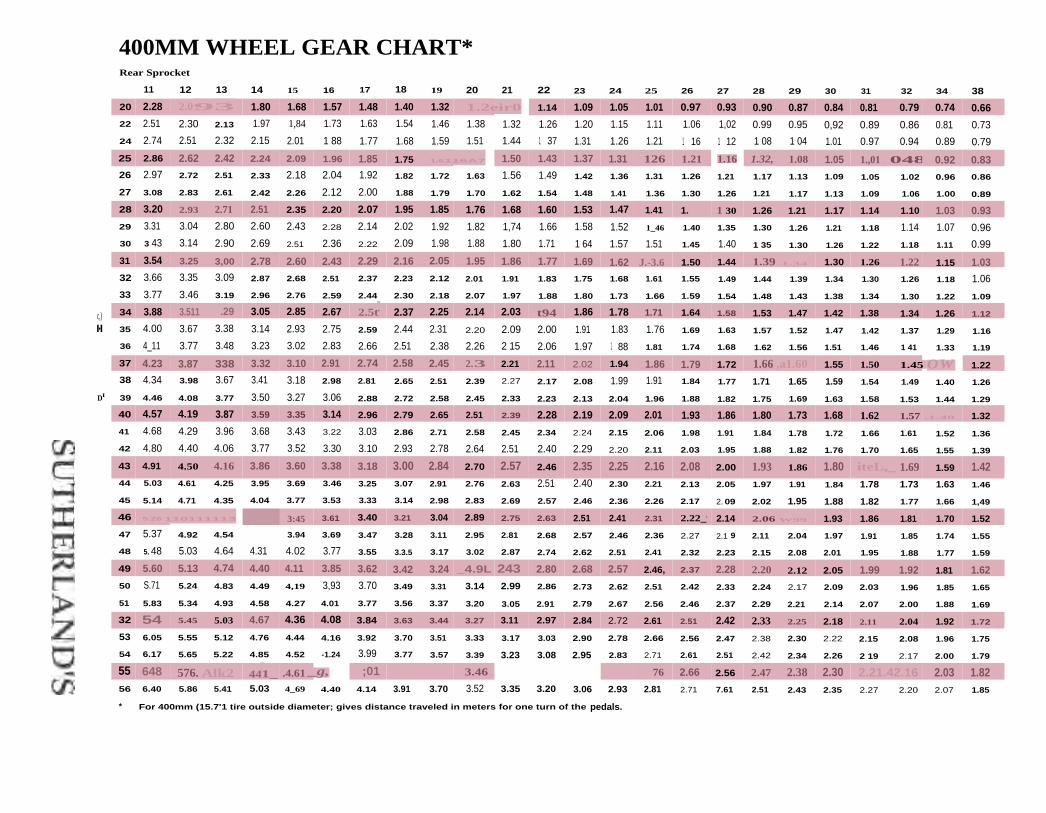
400MM WHEEL GEAR CHART*Rear Sprocket
11 12 13 14 15 16 17 18 19 20 21 22 23 24 25 26 27 28 29 30 31 32 34 38
20 2.28 2.093 1.80 1.68 1.57 1.48 1.40 1.32 1.2eir0 1.14 1.09 1.05 1.01 0.97 0.93 0.90 0.87 0.84 0.81 0.79 0.74 0.6622 2.51 2.30 2.13 1.97 1,84 1.73 1.63 1.54 1.46 1.38 1.32 1.26 1.20 1.15 1.11 1.06 1,02 0.99 0.95 0,92 0.89 0.86 0.81 0.73
24 2.74 2.51 2.32 2.15 2.01 1 88 1.77 1.68 1.59 1.51 1.44 1 37 1.31 1.26 1.21 1 16 1 12 1 08 1 04 1.01 0.97 0.94 0.89 0.79
25 2.86 2.62 2.42 2.24 2.09 1.96 1.85 1.75 1.6116A7 1.50 1.43 1.37 1.31 126 1.21 _ 1.16 1.32, 1.08 1.05 1.,01 .048 0.92 0.8326 2.97 2.72 2.51 2.33 2.18 2.04 1.92 1.82 1.72 1.63 1.56 1.49 1.42 1.36 1.31 1.26 1.21 1.17 1.13 1.09 1.05 1.02 0.96 0.86
27 3.08 2.83 2.61 2.42 2.26 2.12 2.00 1.88 1.79 1.70 1.62 1.54 1.48 1.41 1.36 1.30 1.26 1.21 1.17 1.13 1.09 1.06 1.00 0.89
28 3.20 2.93 2.71 2.51 2.35 2.20 2.07 1.95 1.85 1.76 1.68 1.60 1.53 1.47 1.41 1. 1 30 1.26 1.21 1.17 1.14 1.10 1.03 0.9329 3.31 3.04 2.80 2.60 2.43 2.28 2.14 2.02 1.92 1.82 1,74 1.66 1.58 1.52 1_46 1.40 1.35 1.30 1.26 1.21 1.18 1.14 1.07 0.9630 3 43 3.14 2.90 2.69 2.51 2.36 2.22 2.09 1.98 1.88 1.80 1.71 1 64 1.57 1.51 1.45 1.40 1 35 1.30 1.26 1.22 1.18 1.11 0.99
31 3.54 3.25 3,00 2.78 2.60 2.43 2.29 2.16 2.05 1.95 1.86 1.77 1.69 1.62 J.-3.6 1.50 1.44 1.39 1.34 1.30 1.26 1.22 1.15 1.0332 3.66 3.35 3.09 2.87 2.68 2.51 2.37 2.23 2.12 2.01 1.91 1.83 1.75 1.68 1.61 1.55 1.49 1.44 1.39 1.34 1.30 1.26 1.18 1.06
33 3.77 3.46 3.19 2.96 2.76 2.59 2.44 2.30 2.18 2.07 1.97 1.88 1.80 1.73 1.66 1.59 1.54 1.48 1.43 1.38 1.34 1.30 1.22 1.09
c,) 34 3.88 3.511 .29 3.05 2.85 2.67 2.5t. 2.37 2.25 2.14 2.03 t94 1.86 1.78 1.71 1.64 1.58 1.53 1.47 1.42 1.38 1.34 1.26 1.12
n•n 35 4.00 3.67 3.38 3.14 2.93 2.75 2.59 2.44 2.31 2.20 2.09 2.00 1.91 1.83 1.76 1.69 1.63 1.57 1.52 1.47 1.42 1.37 1.29 1.16
36 4_11 3.77 3.48 3.23 3.02 2.83 2.66 2.51 2.38 2.26 2 15 2.06 1.97 1 88 1.81 1.74 1.68 1.62 1.56 1.51 1.46 1 41 1.33 1.19
37 4.23 3.87 338 3.32 3.10 2.91 2.74 2.58 2.45 2.3 2.21 2.11 2.02 1.94 1.86 1.79 1.72 1.66 ,a1.60 1.55 1.50 1.45 OW 1.22
38 4.34 3.98 3.67 3.41 3.18 2.98 2.81 2.65 2.51 2.39 2.27 2.17 2.08 1.99 1.91 1.84 1.77 1.71 1.65 1.59 1.54 1.49 1.40 1.26
DI 39 4.46 4.08 3.77 3.50 3.27 3.06 2.88 2.72 2.58 2.45 2.33 2.23 2.13 2.04 1.96 1.88 1.82 1.75 1.69 1.63 1.58 1.53 1.44 1.29
40 4.57 4.19 3.87 3.59 3.35 3.14 2.96 2.79 2.65 2.51 2.39 2.28 2.19 2.09 2.01 1.93 1.86 1.80 1.73 1.68 1.62 1.57 .1.48 1.32
41 4.68 4.29 3.96 3.68 3.43 3.22 3.03 2.86 2.71 2.58 2.45 2.34 2.24 2.15 2.06 1.98 1.91 1.84 1.78 1.72 1.66 1.61 1.52 1.36
42 4.80 4.40 4.06 3.77 3.52 3.30 3.10 2.93 2.78 2.64 2.51 2.40 2.29 2.20 2.11 2.03 1.95 1.88 1.82 1.76 1.70 1.65 1.55 1.39
43 4.91 4.50 4.16 3.86 3.60 3.38 3.18 3.00 2.84 2.70 2.57 2.46 2.35 2.25 2.16 2.08 2.00 1.93 1.86 1.80 iteL,_ 1.69 1.59 1.4244 5.03 4.61 4.25 3.95 3.69 3.46 3.25 3.07 2.91 2.76 2.63 2.51 2.40 2.30 2.21 2.13 2.05 1.97 1.91 1.84 1.78 1.73 1.63 1.46
45 5.14 4.71 4.35 4.04 3.77 3.53 3.33 3.14 2.98 2.83 2.69 2.57 2.46 2.36 2.26 2.17 2. 09 2.02 1.95 1.88 1.82 1.77 1.66 1,49
46 5.26 110111113 3:45 3.61 3.40 3.21 3.04 2.89 2.75 2.63 2.51 2.41 2.31 2.22_. 2.14 2.06 W99 1.93 1.86 1.81 1.70 1.52
47 5.37 4.92 4.54 3.94 3.69 3.47 3.28 3.11 2.95 2.81 2.68 2.57 2.46 2.36 2.27 2.1 9 2.11 2.04 1.97 1.91 1.85 1.74 1.55
48 5. 48 5.03 4.64 4.31 4.02 3.77 3.55 3.3.5 3.17 3.02 2.87 2.74 2.62 2.51 2.41 2.32 2.23 2.15 2.08 2.01 1.95 1.88 1.77 1.59
49 5.60 5.13 4.74 4.40 4.11 3.85 3.62 3.42 3.24 _4.9L 243 2.80 2.68 2.57 2.46, 2.37 2.28 2.20 2.12 2.05 1.99 1.92 1.81 1.6250 S.71 5.24 4.83 4.49 4,19 3,93 3.70 3.49 3.31 3.14 2.99 2.86 2.73 2.62 2.51 2.42 2.33 2.24 2.17 2.09 2.03 1.96 1.85 1.65
51 5.83 5.34 4.93 4.58 4.27 4.01 3.77 3.56 3.37 3.20 3.05 2.91 2.79 2.67 2.56 2.46 2.37 2.29 2.21 2.14 2.07 2.00 1.88 1.69
32 54 5.45 5.03 4.67 4.36 4.08 3.84 3.63 3.44 3.27 3.11 2.97 2.84 2.72 2.61 2.51 2.42 2.33 2.25 2.18 2.11 2.04 1.92 1.72
53 6.05 5.55 5.12 4.76 4.44 4.16 3.92 3.70 3.51 3.33 3.17 3.03 2.90 2.78 2.66 2.56 2.47 2.38 2.30 2.22 2.15 2.08 1.96 1.75
54 6.17 5.65 5.22 4.85 4.52 -1.24 3.99 3.77 3.57 3.39 3.23 3.08 2.95 2.83 2.71 2.61 2.51 2.42 2.34 2.26 2 19 2.17 2.00 1.79
55 648 576. Alk2 4411_ .4.61 _g, ;01 3.46 . 76 2.66 2.56 2.47 2.38 2.30 2.21.42.16 2.03 1.8256 6.40 5.86 5.41 5.03 4_69 4.40 4.14 3.91 3.70 3.52 3.35 3.20 3.06 2.93 2.81 2.71 7.61 2.51 2.43 2.35 2.27 2.20 2.07 1.85
* For 400mm (15.7'1 tire outside diameter; gives distance traveled in meters for one turn of the pedals.

INDEXAAbbreviations 17-2Accushift see Indexing SunTourAermet 100 0-5Alignment of bearings 0-9, 10-8
bottom bracket 0-13cartridge hubs 10-8hub 0-11head tube 0-11fork crown 0-12steer tube 0-12
Alloy 0-5, 0-6crank bolts 2-6
Aluminum 0-5, 0-8, 14-4, 14-5Annealing 0-6Axle
bearing alignment 0-10, 10-8, 10-9front huh 10-2, 10-4rear hub 10-3, 10-5 thru 10-7
freewheel clearance 5-8thread size 10-6, 10-7
tapers 2-4 thru 2-6thread chaser
markings on 10-12use of 0-8
BBall bearing see bearingBall cage British for ball retainerBall retainer sizes 10-2Ball sizes
bottom bracket 3-2freewheel 4-2headset 14-9 thru 14-17hubs 10-2, 10-3
Bead see tireBearing
aligning races 0-9 thru 0-14bottom bracket
cartridge 3-34 thru 3-54retapping 0-13, 0-14sizes 3-2 thru 3-5widths 3-6
cartridge 0-10 (see also bottom bracket, hubs)headset
mounting 0- 11, 0-12o-rings 14-18sizes 14-9 thru 14-17
hubcartridge 10-8 thru 10-11rear, mounting 0-11sizes 10-2, 10-3
life 0-10, 3-4, 10-8mounting 0-10 thru 0-14retainers 10-2sealed 0-10, 3-36 thru 3-54, 10-8 thru 10-11types and design 0-9, 0-10
Beryllium 0-5
Bicycle parts guide 17-10, 17-11Block British' for multispeed freewheel
(see Freewheel)Bottom bracket
ball size 3-2ball track 3-4bearing race diameter 3-4cartridge 3-36, 3-37
design elements 3-38 thru 3-54cottered crank
cotter sizes 2-23spindle sizes 3-56 thru 3-58
cotterless crankspindle (axle)
bolt and nut threads 2-2interchangeability charts 3-8 thru 3-12,
3-14 thru 3-33markings 3-8, 3-28replacement 3-7, 3-14shouldered 3-35straight 3-34tapers 2-4 thru 2-6, 3-14types 3-7, 3-34, 3-35
Campagnolo 3-28 thru 3-33JIS and clone 3-8 thru 3-12non-JIS 3-14 thru 3-27
extractors (crank)fit and installation 2-4 thru 2-6sizes 2-2, 2-3
cup-spindle compatibility 3-4, 3-5cups 3-2 thru 3-5, 3-8, 3-29tacing tool 0-13, 0-14interchangeability 3-7 thru 3-33makes and models, design and service
notes 3-38 thru 3-58shell width 3-6, 3-8spacer, freewheel 3-14spindle end factor 3-15tapers, angles and lengths 2-4 thru 2-6thread
sizes 3-2stripped, tapping 0-13, 0-14
unthreaded shells 3-37Books, list of 17-14Brakes, caliper or rim
cantilever 13-2 thru h 13-12center-pull 13-26 thru 13-28delta 13-26 thru 13-28hydraulic 13-30 thru 13-38levers 13-28, 13-29roller cam 13-14 thru 13-16shoes
cantilever set-up 13-2non-standard shoes and pads 13-39
side-pull 13-17 thru 13-25straddle cables and hangers
non-standard 13-40
(continued next page)
SUTHERLAND'S

INDEX Brakes (cont'ch
set-up 13-2 thru 13-6U-brakes 13-12, 13-13
British see also nationality, standard, thread
CCable
casing 5-6casing caps 5-6, 5-7indexing 5-2 thin 5-4, 5-6
Cadence pedal speed in RPM, see gear sizeCarbon fiber 0-5Cartridge
bearingbottom bracket 3-34 thru 3.54hubs 10-8 thru 10-1 1
suspension 15-35Chain
alignment 10-5bushings 2-20cutting 2-22installing 4-12length 5-3recommendations, indexing 5-8, 6-2, 6-8, 7-2,
8-2, 9-7size 2-20, 2-21
Changer see derailleurChainline 3-15, 10-5Chain ring
adapters 2-16, 2-17alignment 10-5measuring 2-9bolts 2-8interchangeability 2-10 I h ru 2-19sizes 2-10spacers 2-8, 2-9, 2-16
Chainstay, tube size 15-56Cleats 1-3 thru 1-7Clincher see tireCluster see freewheelCog see sprocketCone wrench sizes 10-3Conversion see unitsCotters, sizes 2-23
see also bottom bracketCotterless see bottom bracketCrank
arm lengths 2-7bolts, alloy 2-6cotterless 2-2 thru 2-6cot ters 2-23crank arm interchangeability 2-10 thru 2-16extractors, cotterless 2-2, 2-3fit on spindle 2-4 thru 2-6installing cotterless 2-4low profile vs. high profile 2-7one-piece Ashtabula 0-3, 3-58pedal sizes and markings 1-2
spindle fit 2-4 thru 2-6standards 0-3, 0-4super low profile 2-7, 3-34tapers, angles and lengths 2-4 thru 2-6thread sizes 2-2, 2-3
Crossing pattern see spokesCrown race cutter, use of 0-12Crown race sizes 14-2 thru 14-4Cutting operations 0-6 thru 0-9
DDamping 15-3, 15-5, 15-6, 15-7, 15-10Derailleur (see also Indexing Chapter 5)
Campagnoio Chapter 6front 6-7rear 6-5, 6-6rear, non-indexing 6-6
Grip Shift Levers Chapter 9front 9-3parts interchangeability 9-5rear 9-2
Indexing derailleur see IndexingMavic Chapter 9
front 9-9rear 9-7rear electronic 9-7rear, non-indexing 9-8
Sachs-Huret Chapter 6 pages 6-8 thru 6-12front 6-12rear 6-10rear, non-indexing 6-11
Shirnano Chapter 7front 7-10, 7-11non-indexing front 7-11 thru 7-14rear 7-5 thru 7-7rear, non-indexing 7-7 thru 7-9
Simplex Chapter 9front 9-11rear 9-10
SunTour Chapter 8front 8-11 thru 8-14rear 8-6 thru 8-8rear, non-indexing 8-9, 8-10
Development, metric gear formula 17-12Drilling 0-7Drop-out
alignment 0-10dimensions 7-4, 8-5models 7-4spacing 10-15threads 15-57
EEnglish see standard, nationality, threadERTRO European Tire and Rim Technical
(continued next page)
SUTHERLAND'S

INDEXFFacing
bottom bracket 0-13, 0-14 (illustr.)head tube 0-8, 0-11, 0-12
Fender eyelet size (mud guard) 15-57Filing 0-9Fits and tolerances 0-9
(see also part name)Fixed cup see bottom bracket cupsFixed gear hubs 4-49, 11-18, 11-31, 11-33, 11-34Fork
aluminum 3-2crown, race cutting 0-12rake 15-3, 15-10 thru 15-51, 15-57replacement 15-57, 15-58suspension 15-2 thru 15-55
glossary 15-3, 15-4makes and models, design and service
notes 15-10 thru 15-51parts
bushing 15-9crown 15-8, 15-10damping 15-5 thru 15-7, 15-10fork brace (brake bridge) 15-8sag 15-4seals 15-9sliders 15-9stanchion 15-8, 15-9steerer tube 15-7, 15-10
troubleshooting 15-52 thru 15-55types:
air/oil 15-6coil 15-5elastomer 15-7, 15-10linkage/pivot 15-2slider-telescoping 15-2, 15-9
Fractionsconversion to millimeters 17-8, 17-9in tire marking 12-3, 12-4
Framecutting operations 0-6 thru 0-9materials 0-5, 0-6tube size 15-56
Freehubs see freewheelFrench see also nationality, standard, thread
wire gauge sizes 11-5, 17-6Freewheel and freehub
class of fit 4-2, 4-49clearance 4-4, 4-16, 4-17, 4-31, 4-37, 5-8,
10-6derailleur capacity see derailleursfixed gear 4-49interchangeability 4-2markings 4-3mounting 4-4, 4-6problems to avoid 4-4removing 4-5, 4-6, 4-7 thru 4-12removers 4-4 thni 4-11
SUTHERLAND'S
single-speed 4-49spacer 4-16, 4-17, 4-19, 4-21, 4-25, 4-27, 4-29, 4-30,
4-31, 4-33, 4-35, 4-37, 4-40, 4-41, 4-44, 4-45spacing, freewheel drop-out 5-8sprocket
assembly and removal 4-6, 4-12interchangeability 4-13 thru 4-48
thread sizes 4-2
GGauge
drop-out alignment tool 0-11thread pitch 4-2wire size designation 1 1 -5, 17-6
Geared hubfixed gear, hub shell 4-49internal multi-speed, gear table 16-19
Gear hanger derailleur mounting lug 15-57Gear size
formula 17-12charts 17-15 thru 17-24
Gear tables 16-19, 16-34, 16-53, 17-15 thru 17-24Gooseneck we stemGrinding 0-8Grip Shift see Indexing
H1 landlebars 14-20Hanger
derailleur mounting lug 15-57British: for bottom bracket
Hand tools, list of essentials 0-15, 0-16Hardening 0-6Ifeadset
aluminum 14-4bearing alignment 0-11binding 14-5, 14-7installing 14-5 thru 14-8lockouts 14-18markings 14-3mixing parts 14-5, 14-6notes 14-19o-rings 14-18oversize 14-10 thru 14-17press fit 14-4replacing 14-5size chart 14-9 thru 14-19standards 14-2, 14-3, 14-19tandems 14-3threadless 14-8, 14-17
Head tool 0-11Head tube 0-11, 14-2, 14-4 thru 14-8Heat treating 0-6High pressures British for high pressure wired-
on tires, see tireHonked bead tire type 12-2 thru 12-15
(continued next page)

INDEXHooked edge rim type 12-2 thru 12-15 rear indexing 7-5 thru 7-7Hub rear non-indexing 7-7 thru 7-9
ball sizes 10-2, 10-3 shift levers ISIS) 7-3, 7-4bearing alignment 0-11, 10-8, 10-9 Simplex 9-9, 9-10cartridge bearing, assembly and SunTour Chapter 8
disassembly 10-10, 10-11 capacity 8-6, 8-7chainline 3-15, 10-5 cassettes and freewheels 8-3fixed gear 4-49 chain recommendations 8-2flange height 11-3 drop-out recommendations 8-5freehub 4-17, 4-31, 4-37 front derailleurs 8-11 thru 8-14front axle dimensions 10-4 rear indexing 8-6 thru 8-8geared see geared hub rear non-indexing 8-9, 8-10internal geared Chapter 16 shift levers (Accushift) 8-2, 8-4, 8-5measuring 11-6, 11-7, 11-38, 11-46, 11-62, 11-72, SunTour compatible with Shimano 8-2
11-82, 11-92, 11-94, 11-99, 11-101 shift lever (see also various makes above)models, index 11-2 brazed-on bosses 5-5multi-speed, internal Chapter 16 troubleshooting 5-8rear, axle dimensions 10-5 thru 10-7 spacing 4-21, 6-2, 7-3skewers, quick release 10-12 troubleshooting 5-9 thru 5-14thread chaser markings 10-12 Inflation 12-16
Inner tubeI it 12-2
Indexing inflation 12-16about index shifting 5-4 ISO International Standards Organizationadjustments background 0-4
derailleurs 5-3 bottom bracket 3-2, 17-2, 17-3(see also various makes below) crank cotters 2-23, 17-2, 17-3
frames 5-3 crank extractors 2-2, 2-3cable 5-6 crank tapers 2-5, 17-3cable casing 5-6 fork 17-5casing caps 5-6, 5-7 freewheel 4-2, 17-4chain recommendations 5-8, 6-2, 6-8, 7-2, 8-2, 9-7 handlebar 17-4checklist 5-2 headset 14-2, 14-3, 17-4freewheel drop-out spacing 5-8 hub and axle 10-4, 10-6, 10-7, 17-4makes and models pedal 1-2, 17-3
Campagnolo Syncro and Syncro 11 Chapter 6 rim 12-2, 12-8 thru 12-15capacity 6-3, 6-5, 6-6 safety standards 17-5chain recommendations 6-2 spokes 11-5, 17-2, 17-5front indexing 6-7 summary of standards 17-2 thru 17-5rear indexing derailleur 6-5, 6-6 thread markings 17-2shift levers 6-2, 6-3 tires 12-2 thru 12-15
syncro lever inserts 6-4 Internal geared hub Chapter 16Grip Shift 9-2 thru 9-6 3-speed 16-35Mavic 9-7 thru 9-9 5-speed 16-20
Lap electronic 9-7 7-speed 16-2, 16-37Sachs-Huret ;IRIS 6-8 thru 6-12 gear table 16-19, 16-34, 16-51
capacity 6-8 troubleshooting 16-6, 16-7, 16-41, 16-42chain recommendations 6-8 Italian see standard, nationality, threadfront non-indexing derailleurs 6-12rear indexing 6-10rear nun - indexing 6-11 Jauge de Paris French wire gauge designationsshift levers indexing 6-9 11-5, 17-6
Shimano Chapter 7 JIS Japan Industrial Standard 0-3, 10-7, 14-2capacity 7-3chain recommendations 7 -2drop-out recommendations 7-4 Left-handed threadsfront indexing 7-10, 7-11 markings on 3-2, 3-3, 17-2front non-indexing 7-11 thru 7-14 (continued next page)
SUTHERLAND'S

Left-handed threads (cont'd) with head tool 0-I I
use on Rear hub dimensions 10-5 thru 10-7, 11-7 thru 11-35bottom bracket 3-2 Retainers 10-2crank extractors 2-3 Ri m
fixed gear lockrings 4-49 brake radius 12-8 thru 12-15freewheel sprockets 4-12, 4-47 correction factors I 1-108pedals 1-2 cross sections, classic 12-7
Length see units markings 12-3, 12-4Levers see indexing measurements 11-108, 12-5link wires 13-3 size and tire fit 12-2Locking collars 3-34 size chart 12-8 thru 12-15Lockring spoke end diameter 17-12
bottom bracket markings 3-3, 3-35 spoke length correction factors see spokescollars 3-34 theoretical rim radius 11-108fixed gear 4-49
Lubricationmachining and cutting operations 0-6 thru 0-13 Safety standards, see ISO
Seat post 15-59, 15-60M SER shell to end right 3-15Materials 0-5, 0-6 Sew-up tire with inner tube sewn in 12-2, 12-16Metric see units, threads Sharpening 0-7Milling (1-8, 0-11 Shift levers see indexing
bottom bracket 0-13, 0-14 Shoehead tube 0-11, 14-6, 14-7 brakes, type 13-6
Mountain bikes compatibility with pedals 1-4drop-outs 0-11 size conversion chart 1-7suspension forks Chapter 15 Single-speed, freewheel and fixed gear hub 4-49
Mud guard British for fender 15-57 Spanner British for wrenchMulti-speed internals see hubs Spindle see bottom bracket spindle
SpokesN large flange hubs 11-3Nationality see also units, threads, standard of parts 0-4 length formula 17-12, 11-108
Nipple see spoke nipple lengths Chapter 11calculating lengths 11-3
O flange diameters 11-3, 11-4Oil hubs, large flange 11-3
viscosity 15-3, 15-6 first step charts for various hubs 11-6 thru 11-35weight 15-3, 15-6 second step charts for spoke patterns
27" 11-38
700C 11-46Pedal 1-2 thru 1-7 26" M - 113 11-62
clipless 1-3 thru 1-7 26" other 11-72shoes, matching 1-4 24", 22" 11-82
Pedal arm see crank 20" 11-92Plug and play 8-2 18", 17" 11-99Pulley pins, Shimano 7-5 16" 11-10]Pressure, units conversion 12-16 14" 11-104PSI pounds per square inch, unit of pressure 12-16 12" 11-106
10" 11-107third step chart for rim listings
Quick release skewers 1 0-12 27" 11-40700C 11-48
R 26" MTB 11-64Race see bearing 26" other 11-74Radial bearing 0-9 24", 22" 11-84Rake, of fork 15-3, 15-10 thru 15-51, 15-57 2(1" 11-94Reaming 0-8 18", 17" 11-100
bottom bracket threads 0-13 (continued next page)
SUTHERLAND'S

INDEX16" 11-102 Toe clip 1-214" 11-105 Tolerance 0-9 tsee also part name)12" 11-106 Tools10" 11-107 drop-out alignment gauges 0-11sew ups see end of listings for nearest inch size essential, list of 0-15, 0-16tubulars 11-56, 11-78, 11-89, 11-98, 11-100, freewheel 4-5, 4-7 thru 4-11, 4-49
11-103, 11-105 suspension 0-16rim correction factors, calculating 11-108 Torque ratings and specifications 17-13
nipple 11-3, I I-5 TPI threads per inch 0-2number of spokes 11-4, 11-109 Tuberadial patterns 11-4 frame tube size 15-56Standard Wire Gauge 11-5, 17-6 inner tubethreads 11-5 fit 12-2
Sprints British for sew-ups in flation 12-16Sprocket Tubulars British fin- sew-ups 12-2, 12-16
chainline 10-5 Twist shift levers 6-9, 6-10, 9-2 thru 9-6freewheel Tyre British for tire
assembly 4-2, 4-3interchangeability 4-13 thru 4-48 V
removal 4-12 Valve hole sizes 12-16Standard {see also units, threads)
de facto 0-4150 see ISO Weight conversions 17-7national 0-3, 0-4 Wheel building see spokesthread 17-12 Wheels Manufacturing 10-9tire size designation 12-5, 12-8 thru 12-15 Wheelsmith spoke length calculator 11-3Wire gaugewire sizes 11-5, 17-6 sizes 11-5, 17-6
Steel 0-5, 0-6Stem, diameter 14-20Straddle cable ends 13-5 Zap electronic derailleur 9-7Suspension we forkSWG Standard Wire Gauge 11-5, 17-6
TTerminology
bicycle parts guide, in six languages 17-10, 17-11suspension glossary 15-3
Threadchasing 0-8cutting 0-6 that 0-8, 0-12, 15-7gauge 0-2measuring 0-2Sizes see pan name
standards 0-3, 17-12stripped threads 0-13, 0-14, 3-2
Thrust bearing 0-9Tire
ISO size designation 12-2, 12-3inflation 12-16markings 12-3, 12-4measuring 12-5pressure conversion 12-16rim fit 12-2sizes 12-8 thru 12-16ty pes 12-2width 12-2, 12-6
Titanium 0-5
SUTHERLAND'S

Sutherland's BicycleShop Aids, Inc.
9
1311‘/EFt's crIECKLIST
As raen-dscffs am c•Ic'ssilf4 Indst-
statl and insnu,gemen
l'rarnr),WS
Q1S1r.ba..mou sin dr rastych ir VII es.
• • EICtAellISA539
16 91
pr.5 si) malw sett
ssonaN c.cro
ss for tints teas ,
\rvi
the td1owsn pristitsNsdor attenton
e a5
ear,l) plot c
8ale0,1 and 4 Vestsnns out stab
zieaflrq Liridersmsd any
pssnt address0
hliVB recawed
1 and
e sa
31 rE
ondef stars
a bscsichra.
Please 01535
7 1 orLderstans la15, 51).6
,NAILCA)
YOUR SVIOP NAME HERE
• horse: OA) A2'34234A23 Marrs Streek
4 REPAIR FORMS
RENTAL FORMS
/km LAYAWAY FORMS
Ilirefira..iltsm BOND,4' 4'144 48 GIFT CERTIFICATES ,s
•--"4"1
1,11
HANDBOOKS FOR isov
a
BICYCLE MECHANICS r
1141111- 4. 41ftlftl;414,11 11.1111illeak Orel,-111F
arisigayeow Mtimam
Air
Ara
39057.3
YOUR S
Your Town
Srare2345 - Phone: 11111 123-1234
Main Sheet
RE
Your message
here.
L'DRE Ss
CliAguj,
IMPOqr1151F0._ 1:24:4vort,,Aivr
r
1-800-2 -8_:?10:0 0

fist acrescones sold
;Pith bikehere.
YOUR SHOP HARE HEREt$ •wIbM03•3 1 0 If mastmow*.
r••,•••
Culatan forlabor makes
It Mier tOcharge for
ti me-corl.stir/ling bikeassemble
accessoryinstallation
• Delivery checklist. for a quickcheck before the bike goes outthe door. catches any misad-justment from test rides like aloose seat post.
Buyer sign:
check h SI of
Bieyde Buyer 's
.Agreement.
Easy to read 1-nurrrher a finchesto box or bicycle.with transfer tapeattached. Spaceforadditlonal notessthOire coattailnumber
:90'.03
acidSHOP NAME HEREis ua,i Om5151.: a. ous • tswe. 1 li s t.7. Int
...7. n ... mm.
.......m
- ma.
....
m
MEI=MM.
=•.011 174.
M .., M....IffM
check herewhen tested.
See `imprinting"section for specialmessages to go here
Assembler Writes inntitnner here.
Capersagreement
Qu ick•Re leasePresentationen hack of cur-farrier ropyAssemblychecklist onbock of hardcopy
Bar-codedtag number.
Delieerychecklist.
TYPE DOUBLE E
10" X 8W'4-part carbonless
Type Double E — NowSutherland's hasinventory/Sales Formsfor Computer Printers
A tractor-feed version ofthe Double C with or withoutbar-coded tracking number.
306036
• Includes: Buyers agreement,Assembly checklist. Deliverychecklist. Quick-ReleasePresentation. Bar-coded tagnumber.
• Sutherland's NEW BikeTrackerinventory software will use
these forms. Call us toll-freefor your complimentaryinformational brochure_
Urge your software supplierto incorporate these forms
4 carbonless copies —white for assembly, yellow for
customer. (with Quick ReleasePresentation), pink control copyand white hard copy.
CALL SUTHERLAND'S AT
1800-248-2510 TO ORDER
TYPE E
10" X 51/2"4-part carbonless
A tractor-feed version of theType C form with the additionof the delivery checklist andbar code.
I NVENTORY/SALES TAGSIISSEMSL if entcausT -
r.-. •••3n
usgq.....
Keep Track of YourBicycles Every Step of theRetail Process
These tags keep track ofyour bicycles every step of gipretail process! They serve thedual function of inventory tagsthat help keep track of stock.and they're sales receipts thatgive the customer a completedescription of the bike andaccessories purchased.
If these tags save you oneminute per bike it's worth hav-ing. For instance. if you sell 600bikes. you would enjoy a savingsof 600 minutes or 10 hours. Ifyour shop rate is $30 per hour,you realize a savings of $300!
TYPE DOUBLE C
9'/2" X SW'5-part carbonless
Type Double C5 Carbonless Parts — whitefor assembly. yellow for the cus-tomer (with Quick Release Pre-sentation), pink file copy, greencontrol and white hard copy.
* Includes Bicycle Buyer'sAgreement and Inventory Con-trol System that tracks everystep from stocking to delivery.
♦ Assembly checklist on the backof the hard copy to help insurethat all the details of assemblyare completed. despite iheinterruptions of a bike shop.
.1 3976 :=1==
my07Thatr-CNIJIT
110.11n1- •••• ..• 1•nn ••• •• • • •
"•
wh,n•••••n••n • n• .•n •••10.
1-77 ...I. •— • ... •••
Assenif4Checklist on
back of thehard copy
4 Parts — white copy forpre-assembly: yellow copyshowing indicates that hike isassembled; pink copy showingmeans it's sold. Hard copy isyour complete record filled out.
• Serves two functions:Inventory tag and sales slip.
• Lists make and model ofbicycle and accessories sold.
• End stub is attached to boxwhen bike enters inventory —upon purchase. stub is re-moved and attached to bicycle.
• Write layaway informationon back of hard copy.
Description of The top is
easy to read when ragal rack or file cabaret

• Back has placeto list alterationsand installations.
• Customer getstop white copy.Attach canarycopy to ourinventory/SalesTag to preventthe bicycle from beingaccidentally sold again.
• Sold tag with name goeson the bike or item.
LAYAWAY VAG, •
min SHOP NAME HERErn4Nr ssN,
—Tan SNNUV5 • RIMS MI 103-•
I NS Amapa No
PAYMENT SCHEDULE
Let us save it for vonwith inn-
L AY-AWAY
PLAN
—includesnor tentsigns.
270756
YOUR SHOP NAME HEREnsis.sne
11,[1.1a • How 1-0 • 1 i M•O•ow•wipAro
SPECIAL
ORDER
i!
Top copy — C uslorner fillsout name. address and signsname.
Pick-up date andnotification check-off.
YOUR SHOP NAME HEREi n Nutt Stvis
v./ Tow, MAA "NS • P•••••• 12.3,27.rum N.A.,. IMA
POST:AND
Second copy —Enter ordering info
hem Informationis visible while inSutherland's TagRack or file
Large stub attaches
to hike or part so ftdoesn 't get acciden-tal y sold to thewrong person.
SPECiA;
Third copy Tear off order-
ing info and
drop postcardm mail when
tern arrives et
your shop
Back ofpostcard
AMA SPE;
1,, S., 1141e
Gift Certrfteote
advertising signs.
• Available onlywith yourimprint.
All new chapter on frontsuspension maintenanceand repair tips.
All newcliplesspedalcompati-bility chart.
Updatedheadsetcompatibilitychart.
• Sachs and Shimano internal7-speed assembly anddisassembly instructions.
TYPE L / LAYAWAY
1054g" X Vie2-part tag
Promote your LayawaysTurn "lookers" into buyers
through the ease of your lay-away plan. Each order of thesetags includes two tent signs foryour sales counters.
• Designed to work with Suther-land's Bicycle Inventory Tags.
• Simplifies layaways —2 copies plus ID tag for bike.
TYPE S / SPECIAL ORDER
105h3" X 41/4"5-part tag
End special-order confusionTime-saving 3-part tag has acopy for you and customer. plusprovides a postcard/ID stub toinform customer that merchan-dise has arrived.
Item listed here.
her makes
It d
•
•
•
•
•
•
TYPE G/GIFT CERTIFICATE
7 74i" X 43/4"2-part carbonless
Strengthen Saleswith Sutherland'sGift Certificates
SUTHERLAND'S
HANDBOOK FOR BICYCLE
MECHANICS
Sixth EditionWe've packed these 450
pages with the information thatis central to the current revolu-tion of the bicycling industry.
• New specifications onmountain bike equipment.
• Make that sale to the giftshopper in your store withthese certificates.
• Two attractive colors on indi-vidual forms in convenientquantities.
• Each order includesenvelopes and two
Revised spoke length tablesfor over 750 rims — 100pages of spoke lengths includ-ing new numbers for yourspoke length computer!
Updated bottom bracketsection, many new axlelengths and cartridge/spindleinterchangeability charts.
Chainring compatibility withadapter and spacer charts.
REPAIR MANUALS

97649900411 SHIP RARE HERE
Llar kw.tug finul Star r..1. • ,flan• 1111.10 ID.
Toa maw, MIA
CALL SUTHERLAND'S AT 1800-248-2510 TO ORDER
REPAIR TAGS
YOE'REEP.,1tVyi.MORF '
CT
.ABOW OVICJr
RC. EASE 485. n
Quick Release informa-tion is priMed on !heback of the white cus-tomer copy of both forms.
Type 88Same for us Type AA.
except service workI s II of pre-iisted
Type AACustomer Sfyris offfor recommended
work refused
TYPE A B
43/4" X 1-M"2-part tag
Save time and moneythrough increased efficiency.Featuring bright red one inch-high numbers. these tags helpyou to quickly write-up and findrepair hikes. The tags can beimprinted with your shop'sname, address, phone numberand a short message. You'll beable to see your work load at aglance to avoid overbooking.Let work flow smoothly withSutherland's Repair Tags.
COASTER BRAKE I
INTERNALLY GEARED
ROBS HANDBOOK
Instructions on assembly anddisassembly of all major hubson the market, plus many olderhubs that are no longer sold.
• Step-by-step illustrations anda listing of the most commonservice needs of the hubs.
Type A — Service work ispre-listed on a 2-pan carbonedtag. This tag allows you to notebicycle accessories at check in,promised delivery date and me-chanic's sign off. Fits in Suther-land's Tag Racks or hangs ona hook or a nail.
Detachablecustomer claimcheck indicatespromised date
of work'scompletion.
Plaids up to fallour .E. U.SI N
• Interchangeability charts thatdetail common parts withina family of hubs.
• Information on SturmeyArcher AWC 3-speed,Shimano E Type and NKSuper Model 120 coasterbrakes plus Sachs H31023-speed Hub not coveredin previous editions.
These spacious tags are idealfor your shop to create repairorders with specific listing ofservices to be performed. We'veincluded our Quick Release Hubdemonstration on the back ofthe customer's copy so that youcontinue to educate the con-
sumer on this impor-tant safety issue longafter the sale of thebicycle.
Both Double A andDouble B fold to fitwail racks and filecabinets.
Rte-'! RIM==
Folds to fit in Sutherland'sTog Rack with the lidlcustomer name showing.
Type B is the sameas Type A, except all ser-vices are written in by yourshop rather than pre-listed.
Service is pre-listed Simply circlerepair to be done Additional roam on
the back for more work to be lister}.
Desaripiion of bike and aCCf:tb5r1•Fteli
it come in with. goes here
Mechanic signs offo.n Joh here.
I" number SOWS
time finding bike
Customer claim check hasname • address • phone and
rnessage — See -Imprinting' forother ideas.
TYPE DOUBLE A & B
8" X 91/4"3-part carbonless
to be done. Also included is aspace to note recommendationsmade to the customer and asign off as to whether the sug-gested work was accepted orrefused.
The 3-part carbonless tagallows you to give the customera copy of the work to be per-formed when bicycle is droppedoff. This tag also allows you tonote what accessories were onthe bicycle when it entered yourshop, promised delivery dateand mechanic's sign off.
Type Double B — Sameas Double A. except ail servicesare written in by your shoprather than pre-listed.
MEM. MR
•• n••
•
Te*roff stab gr yeA OH the bike soyou can find f he bike by the cus-rorner's •141 71, or large, rpd numbers.
L.V6Ek2 Fr.5394 3 :21
DU{1- 3ia
g 9 1. IT
YOUR SHOP NAME HERE23 4,3M
Tar 5,••F MO • M.,. ,21 ,ratNo.
9E1
Type Double A —Sutherland s most
comprehensive RepairTag allows you to circlepre-listed services orwrite in your owndescription of work
Type A
Type B&Me for us
Type A. exceptservice work hnot pre-listed

Reminrier 20 the cierlt to listhelmet and lock registration
Merchandise sold odours
accessory sales for euer4' rental —
instructions checklist andagreement for the renter
.-0,. n=1•••n [.11.101....b• Nowtm ...or .ffitmira ••••••••••••n ••10.1 n •n• •
•=,•1.1••n•• Imewm
Delivery checklist providesa quick check before the
hike goes out the door
••••VMMII-Erf.••..--.1.1amalamompv••••••••••
........•n••n ••••n ••11••••nnn •••••Nimm•
••-•:7 ono maz.:=:•1
s• swer=immonI
-.A -rre.ir.rin am.
CALL SUTHERLAND'S
-1 800-248-2510-FOR MORE INFORMATION
ON CUSTOMIZING YOUR
FORMS
...ABOUT QUICKRELEASE HUBS.
NEW BICYCLE INFORMATION
YOUR SHOP NAME nERE73 Main Sleir
Tv Tam R.. 43n5 • .m.1111 ,131E511.71.44.0. n
warranties in one handyplace.
• Large enough to handlealmost all owners manuals.
THAN THIS...
YOU NEED TOKNOW MORE...
390573
YOUR SHOP NAME HERE173 Main Shoot
D., Town. State 12345 • Phone: 11111123-1738 ACC
Your message here
Extra linesfor storagecharges
0
b
• n 4 E
ff
OAP
REce YE)
Extra lines forstore hours
2 stores
Extra linefor name
2 storesand extramessage
2 stores
BIKE AMERICAElk Grove L Sacamento
9032 Elk Grove Blvd 6531 Brucevill Rd
6135-5021 423-X35
SCHWINN CYCLERYORMONO SCHWINN VOLUSIA SCHWINN205 S Yongeii15 #11 3132 5 Ridgewood iLIS tI)
Ormond Beach • 577-2425 So. Daytona • 156-0008
Lay-away deposits are non-retu nclable.
SPECIALTY ITEMS OWN
nRIPIAL NORIRISERT 041119
TYPE R / RENTAL7 74;" X filib"3-part carbonless
• Designed specifically for bicy-cle rentals, includes an agree-ment to be signed by renterbefore any equipment leavesyour shop.
• Instructions Checklist inagreement section verifiesthat customer has beenadvised of proper use ofrented bicycle and necessaryauxiliary equipment.
• Quick Release Presentationon back of customer copy.
NEW BICYCLE OWNER'S
ENVELOPE
9" X 6343"
Your professional option fordelivering important papers tothe new bicycle owner!
• Quick Release HubPresentation on back andflap of envelope.
• Keeps owner's manual,receipts, brochures and
I MPRINTING
Special imprint formats areavailable at no additional cost.Save time and money whilegiving your customers valuableinformation with special mes-sages. Here are some helpfulformats:
Logos and trademarks canalso be printed ($40.00 one-time set-up charge). If you havespecial artwork you would liketo include. please call for ourlogo guidelines sheet.
• Size of custom logo areais 3" x 3/4".
'6-VERP I "" I MC'N I TUESIDELIVER woo t"U'' I FA' I ''''T I
DA-E
MAE
0 457081,.,,,t Responsible For Goods Left Over 30 Days.
CYCLE WORLD9.627 Reseda Blvd • Northridge, CA 91324
Phone:15181 349-69005Aorage d •sigpes al $1,slay
xi ass* to days Sher cornoleeen
co_. .•-I,-Ln----.10
Not Responsible For Goods Left Over 30 Days
CYCLE WORLD710 0114EFSIty Avenue
Rochester, NY 14607 • Phone: 2714553£0srr 10-8 Man Yes Fn.. Sat 1 0-6 Sal 12-5
rAit tor wolev naps
.r.=.
.__.La
`6.;0
Not Responsinee For Goods Left Over no Days
Sonny s
BICYCLE WORLD6103-A Wesie',
Greenville, TX 75401Phone: 12141454-3030
Z---•CDCOco,
Not Responsible For Goods Lett Over 30 Days
BYRD'S BICYCLES, INC.1131 4th Si N 1506 54Th Ave. N.
St Pete, Root St Pete, FL 33704Ph, 8%-3791 Ph. 552-5605
coroicncrcoL..,
1...m. I.••••• v

Arolinivs
WECNICW. •
ATCAL2Cti
CALL OR WRITE
FOR A FREE SAMPLE PACKET
TODAY!
FILING MATERIALS & RACKS
Use Sutherland's Tag Racksfor efficient service management.All Sutherland's tags work withthese sturdy grey-painted steelracks that will last a lifetime. Seeyour workload at glance and lo-cate the customer's tag quickly.For a new bike set up — pullthe inventory tag for the hike tobe assembled from your Suther-land's File cabinet and place thetag in the rack along with therepair tags. For a repair —when customer returns you canput your hand on the tag quick-ly. inform them how much therepair costs, then get the bikewhile they write their check.When you've promised all thework you can complete on anygiven day, put in the FULLsign. During thebusy season it'seasier to point tothat FULL sign thantry to explain whyyou can't take onmore work for thatday. Slot dimensionsare 2 7/16" x 85Y16" xV deep. Shippingwt. is 123'4 lbs.
RACKS FOR
SUTHERLAND'S TAGS
2 Sizes Available
• 40-Slot Rack has outsidedimension of 44" x x1 14c." deep.
• 20- Slot Rack has outsidedimension of 22" x 9" x1 1/16' deep.
Divider CardsHeavy-duty varnished Divider
Cards (sold separately) aid ingrouping tags according to theday the work is to be completed.Printed in bold, easy-to-read let-ters. Each card is 41/4" x 73/4"long and fits into the same slotsas the repair tags. Each set
contains:pr.a. 7 Day Cards
(Sunday,Monday, etc.)7 FULL/DONE cardsand 7 MORN-ING/ AFTER-NOON cards.
AVOW.
File CabinetsSimplify ordering bikes by
keeping your inventory at yourfingertips! These convenient,good looking files feature a ny-lon guide for smooth operation.
Type C — Overall dimen-sions of This" x 91/2'" x 16"deep. Will hold about 450completed Type Cforms.
Type E Overall dimensionsof Sr%" x x16" deep. Idealfor holding Type Eforms.
File Guides for Type C• Arrange your inventory tags
by model and frame size.
• Guides are 1/5th cut foreasy indexing.
• Made of heavy card stockfor long use.
• Just the right size for yourinventory forms.
• Available in sets of 100.
Cable TiesA simple way to help organi-
zation. Handy re-usable beadedplastic ties allow you to attachour tags to the bicycles in yourshop. Call for samples.
Sutherland's Bicycle Shop Aids, Inc.P.O. Box 9061 Phone: (800) 248-2510 • (510) 547-3966Berkeley, CA 94709 Fax: (800) 255-1039
Fax Outside USA: (510) 655-5445