methodology for part visualization problem solving ... · 1 methodology for part visualization...
TRANSCRIPT
1
Methodology for part visualization problem solving (reading mutiview technical drawing)
E. Sierra Uria1, M.Garmendia Mugica2, J. Muniozguren Colindres1 and I. Larrakoetxea Madariaga1
1 Faculty of engineering of Bilbao, The University of the Basque Country, Bilbao, Basque Country,
([email protected]; [email protected], [email protected]) 2University School Technical of San Sebastián, The University of the Basque Country ,
San Sebastian, Basque Country, ([email protected])
Abstract Part visualization is a fundamental skill in engineering. It comprises the reading, interpretation and creation of industrial technical drawings, interpreting the different views (multi-view) of an object/piece represented in/shown by any technical drawing. However, engineering students show certain learning difficulties and a high failure rate in subjects such as Technical Drawing and Design. A problem solving model for visualization has first been designed and developed for all kind of industrial objects (Methodology for Part Visualization Problem Solving) within a constructivist framework. The Problem Solving model is the key to all technical knowledge and is an application of the scientific method. To develop this methodology, technical drawing textbooks, research and papers from all around the world have been used. In relation with this methodology, some teaching strategies have been developed. They may be applied by drawing up a programme of specific tasks which takes into account the theoretical contents and procedures involved in part visualization as well as the students’ main difficulties and deficiencies when faced with this kind of problem. This teaching strategy has been applied over the last two years in the first course of Industrial Engineering in the Department of Engineering in Bilbao at the University of the Basque Country. The main aim of this Paper is to show, reason out and discuss this new methodology for part visualization. Other aspects of this study were shown at the 2008 ASEE annual conference celebrated in Pittsburgh. Keywords: part visualization, teaching strategy, problem solving model, constructivism
1. WHY THIS INTERVENTION? There are three main reasons supporting this didactic intervention: In the different subjects studied by future Engineers, some difficulties can be observed in the visualization of parts and the development of spatial capacities (Sierra Uria, Egoitz, 2005) [1]. The ability to mentally visualize and manipulate objects and situations constitutes an essential need in many engineering-related jobs. It is estimated that nowadays, at least 84 majors consider spatial visualization a fundamental need (Smith, 1964) and in some technical jobs, the ability to visualize has acquired an outstanding importance (Maier, 1994)[2]. The third reason supporting this study is that educators need to analyze and continuously look at their own ways of teaching in order to become more effective educators (Fernando Hernández, 1992) [3].
2
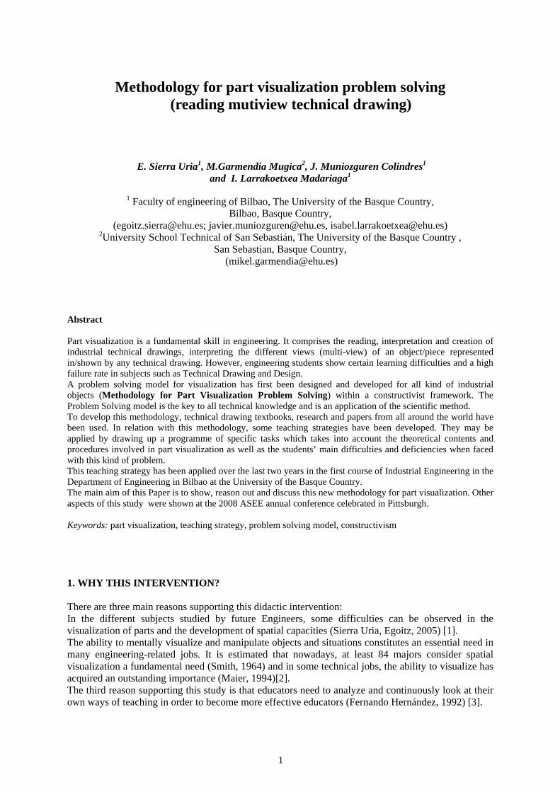
2. DIDACTIC FRAMEWORK There is a need to analyze the specific difficulties arising from the learning of visualization. Educators have often pointed out the difficulties shown by most students in graphic courses when trying to visualize an object using multi-view drawings. These difficulties are mainly due to the inexistence of a systematic process to analyze complex forms (Luzzader and Duff 1986) [4]. The didactic strategy followed in most classrooms could be one of the main reasons for these difficulties. This didactic strategy consists in a visualization of the problems followed by the solutions to those problems, without providing students with a clear explanation on how to solve them; this is, the necessary reasoning during the problem-solving process (Garmendia, 2004) [5] . Students themselves confirm this lack of a problem-solving strategy. Instead, they use the trial-and-error strategy, or they simply rely on intuition. Didactic research in problem-solving states that when students reason, different aspects of inter-related knowledge are put to work. A set of general abilities is used and applied to the different aspects of a subject, thus creating particular ways of reasoning in that subject. This proves that in teaching, besides the theoretical and conceptual knowledge, other contents such as procedural knowledge must be taken into consideration (Guisasola et al. 2003) [6]. Certain aspects must be defined when planning the teaching of specific contents and deciding on the design of the learning process through a program of activities. The intended objectives and the contents are among these aspects that ought to be defined, keeping always in mind the possible difficulties that may arise from the assimilation of the contents by the students. But at the same time, it is necessary to define the strategy that will be followed to achieve a meaningful learning, defining a logical sequence of activities specifically designed for the learning process, as well as the type of assessment that will be used to guide the students and help them improve in their learning. We also come across students who have not developed enough spatial capacity and therefore, they have serious difficulties in understanding and manipulating the parts in space (Navarro,2004) [7]. Mathewson (1999) [8] affirms that educators often forget the importance of the spatial- visualization factor in learning. A review of most text books in this subject shows that little has been done to improve and develop the students' spatial capacity. Engineering textbooks often present orthogonal views, static concepts, theories and ideas with little or no explanation, all of this together with a lack of interpretation of spatial data. It is assumed that the student will be able to overcome the mental challenge and assemble the spatial puzzle. According to Potter (2003) [9] students with a deficient development of spatial capacity need to learn by using static, dynamic and transformational images, as well as the way to combine them in problem solving. Spatial perception can be developed in many ways. For instance, by practicing the modelling and freehand drawing of objects, representing objects in 3D models, manipulating objects in 3D in order to recreate their representations dimensionally, and finally, by experimenting and working with different perspectives or views of the represented part or object both on the blueprint and in the computer image.
Figure 1. Bertoline 2003 [10]
On the other hand, a thorough review of the literature in technical drawing textbooks has not been successful in finding a clear, concise, and fully developed method to solve visualization problems using procedural contents. (Sierra Uria, Egoitz, 2005) [1] .
2.1 Didactic Framework This Visualization Didactic Unit and the Programming of Activities based on the new Methodology for Part Visualization Problem Solving has been developed under a constructivist view and within the European Higher Education Framework. The highlights of this framework are the following: • The student builds up his knowledge • The new knowledge has to be significant to the student • The student's previous knowledge must be taken into account • The teacher must guide students in their learning process

3
• In the learning process, some “cognitive conflicts” are bound to arise • The learning process will promote “zone of proximal development” [11] between the students • The student´s work is measured by the ECTS (European Credit Transfer System) • The students will know at all times the result of their effort and their progress in the learning process, as
well as the reward corresponding to their effort (evaluation) • The student holds the main responsibility for his own learning
2.2 Used Tools Nowadays, ICT (Information and Communication Technology) offers a variety of complementary tools that are very helpful in the teaching/learning of every subject, including the visualization of parts. The tools used in this Visualization Didactic Unit are the following:
2.2.1 Slide animation By using a computer (PC) with a screen output connected to a projector we can easily modify slides and go up and down in the solving process. These slides can also have attached photos and other documents such as videos and CAD models.
, )-Dibujar prisma (simetría)-Dibujar plano de corte-Dibujar paredes-Dibujar elementos característicos-Comprobar
Figure 2. Slide 6 of 7 from the solving process
2.2.2 Virtual models (CAD) Virtual models created by computers with a CAD program can be easily rotated and sectioned in any moment depending on the needs of the teacher or the student. We can move from a perspective to multi-views or vice versa quickly. In this way, the difficulties arising from the understanding of the relationship between the spatial reality of a part and its representation on the technical drawing are minimized.
Figure 3.. CAD virtual model
2.2.3 Physical models (CAD) According to a number of authors, in order to increase the spatial capacity of students it is necessary to work in space with 3D models which can be turned, moved, and worked on mentally, for example, by obtaining their projections (Devon et al. 1994) [12]
Steps: - Analyzing types of cutting views/views (identifying cutting planes). - Analyzing types of pieces (prisms, symmetry, elements) - Prism drawing (symmetry) - Drawing the cutting view plane - Drawing walls - Drawing characteristic elements - Check-up

4
Following Bertoline et al. (1995) [13], another way of improving the students' ability when visualizing an object or a 3D scene is to make their experience as realistic as possible.
Figure 4.. Physical models
Therefore, real physical models have been used. Some of them are made of cardboard but most of them are made with rapid prototyping machinery in the Product Design Laboratory in Bilbao (www.ehu.es/PDL/) at the Department of Engineering, University of the Basque Country.
3. METHODOLOGY FOR PART VISUALIZATION PROBLEM SOLVING, COMPREHENSION INDICATORS AND ACTIVITY PROGRAM This newly developed Methodology for Part Visualization Problem Solving is mainly based on three sources:
• The analysis of the students´ difficulties when faced with Visualization problems • The analysis of the experts´ solutions to Visualization problems • The analysis of textbooks and published research papers in the area of Engineering Graphics and
Engineering Education In this new Methodology [14] the Problem Solving model has become the key to articulate all the necessary knowledge for the the solving of this kind of problems. The Problem Solving model, which is an application of the scientific method, is the basis of all technical knowledge.
Figure 5.Scientific method and Problem Solving Model
When faced with a Visualization Problem, the data (multi-views) must first be analyzed and, according to these analyzed data, a strategy must be decided on. The problem can be solved element by element (sub-problems), by drawing a sketch and checking its concordance with the data. In an iterative process, all the elements of the object must be solved. Once the whole object is obtained, new views/cutting views can be created using the same method (analyzing the new viewpoint / cut viewpoint and then, solving element by element).
5
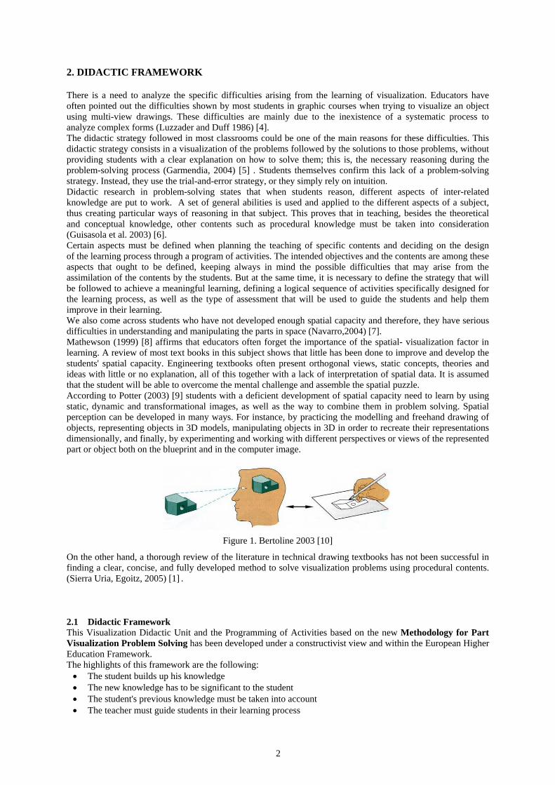
Figure 6.Methodology for Part Visualization Problem Solving
3.1 Comprehension indicators In order to solve the visualization problems in any kind of industrial object, the following comprehension indicators must be mastered/fluently used. The first eight indicators basically correspond to conceptual knowledge and the last two indicators, while containing conceptual skills, correspond essentially to procedural knowledge.
3.1.1 Fundamentals of representation systems These fundamentals consist of a sound knowledge of the basics of the main representation system of the orthogonal cylindrical projection (multi-view), including standardization, and how projections are created (from 3D to 2D) as well as the reason for visible and hidden lines. Another important aspect is achieving a sound knowledge of the basics and main features of the axonometric perspective and oblique projections (3D) To visualize the piece in space (3D) it is necessary to proceed in reverse to what has been done to create the views (2D). There sound be a good knowledge of the relationship between the systems of representation.
Figure 7. Fundaments of multiview representation
3.1.2 Conditions or rules of correspondence (6 rules) The rules derived from the type of projection (parallel projection / cylindrical and orthogonal) must be mastered. This is: 1. The projections of a point will be aligned in the different views. 2. The dimension between two points (x, y, z) will be the same for different views 3. Parallel lines in the different views will remain always parallel. 4. The form of flat surfaces remains equal in the different views unless it is seen as a line. In this case, the
surface (plane) is parallel to the visual 5. Two contiguous areas separated by a line cannot be on the same plane
Breakdown of the analysis
(subproblems)
Sequence (general-to-detail
left-to-right top-to-botton
outside-to-inside)
MINIMUM REQUIRED KNOWLEDGE
1- understanding the fundamentals of multiview, axonometeic and oblique projections 2- understanding the principles of orthographic projection (rules) 3-understanding the different types of planes and their projection 4-understanding the different solid primitives and their projections 5-understanding the different types of surfaces, the tangency and intersection between surfaces and their projections 6-understanding the fundamentals of the vacuum (- material, boolean) 7-understanding the different types of cutting planes and their attributes 8-understanding the main features commonly found in mechanical components (rib, web, holes, lug, chamfers, …) 9- understanding the different strategies of visualization 10-understanding the fundamentals of sketching (multiview, axonometric, oblique)
FRONT VIEWPOINT
TOP VIEWPOINT
LEFTSIDE VIEWPOINT
VISUALIZATION 3D Rough sketch to
represent the main features (low ability)
(freehand/mental, expert mental)
3D Refined sketch (high ability) (freehand)
3D
METHODOLOGY FOR PART (multiview drawing) VISUALIZATION PROBLEM SOLVING
Qualitative data analysis: 1.- View : kind of view/section view 2.- Solid :
- the general type of the component (main feature) linked with the visualization strategy : (boxing-in, revolving geometries, vacuums, symmetry, …)
- analyzing positive and negative solid primitives of each feature - analyzing the common features of mechanical components 3.- Surfaces: - type of planes, contours - type of curved surface, tangencies, intersections - inside/outside surfaces 4.- Identifying the vertex Visualization strategies : - identifying the different planes ( flat surfaces) - removing from the boxing-in - decomposing into simpler geometric form (solid primitives) - visualization of the cutting plane - visualize the vertex - identifying axes/revolving geometries - identifying material/vacuum (positive/negative, boolean) - the attributes of common features in mechanical components - The attributes of surfaces tangency and intersections Solving (making the image) / Drawing (mental/freehand):
- Sketching process (principle axes/boxing-in, auxiliary points and lines, proporcional
- Sketching sequence (linked with the problem-solving sequence) Analysis of results (confirmation of the image) - The concordance with the data
Iterative process to solve
the main features
(breaking down the elements)
Analyzing -Identify the viewpoint in 3D Solution/Drawing (freehand, mental): - Sketching process (view/cutting plane line alignment, auxiliary lines, proporcional, - Sketching sequence (axes, contours, features,…) Results analyze
New views and section views (low ability, freehand)

6
6. The dimension of a feature are in a true scale when it is perpendicular to the visual projection. When it is not perpendicular, it will be smaller than true scale.
Figure 8.Rule 4
3.1.3 Types of planes and characteristics of its projections There must be a sound knowledge of the different types of planes (3D) according to their relationship with the projection (parallel, project planner and oblique) as well as of the characteristics of their projections (2D).
3.1.4 Types of solid primitives and characteristics of its projections It is necessary to be very well acquainted with the various geometric main elements (3D) and the characteristics of their projections (2D) both when they are solids or surfaces (prism, cube, cylinder, cone, sphere, geometries of revolution).
x
z
y
x
z z
y
x
y
O
Figure 9. Oblique plane Figure 10. Cylinder
3.1.4 Tangency and intersection between surfaces This means mastering the tangency between surfaces (3D) and their representation (2D) (lines of contact, finite line) as well as the various intersections between surfaces (3D) and their representation in the most basic areas (plane, cylinder, cone, sphere)
Figure 11. Tangent surfaces and Intersection between cylinder and plane
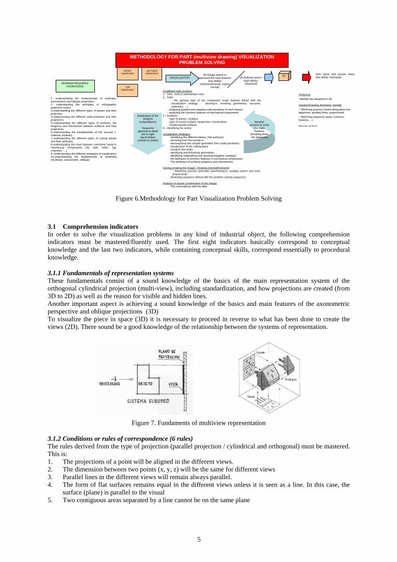
3.1.6 Fundamentals of vacuum (material -) This involves having a sound knowledge of reasons for the existence of vacuum and its relationship with the material (3D), as well as knowing how to represent the existing vacuum in the projections (2D) (hidden lines)
7
Figure 12. Vacuum = material (+) – material (-)
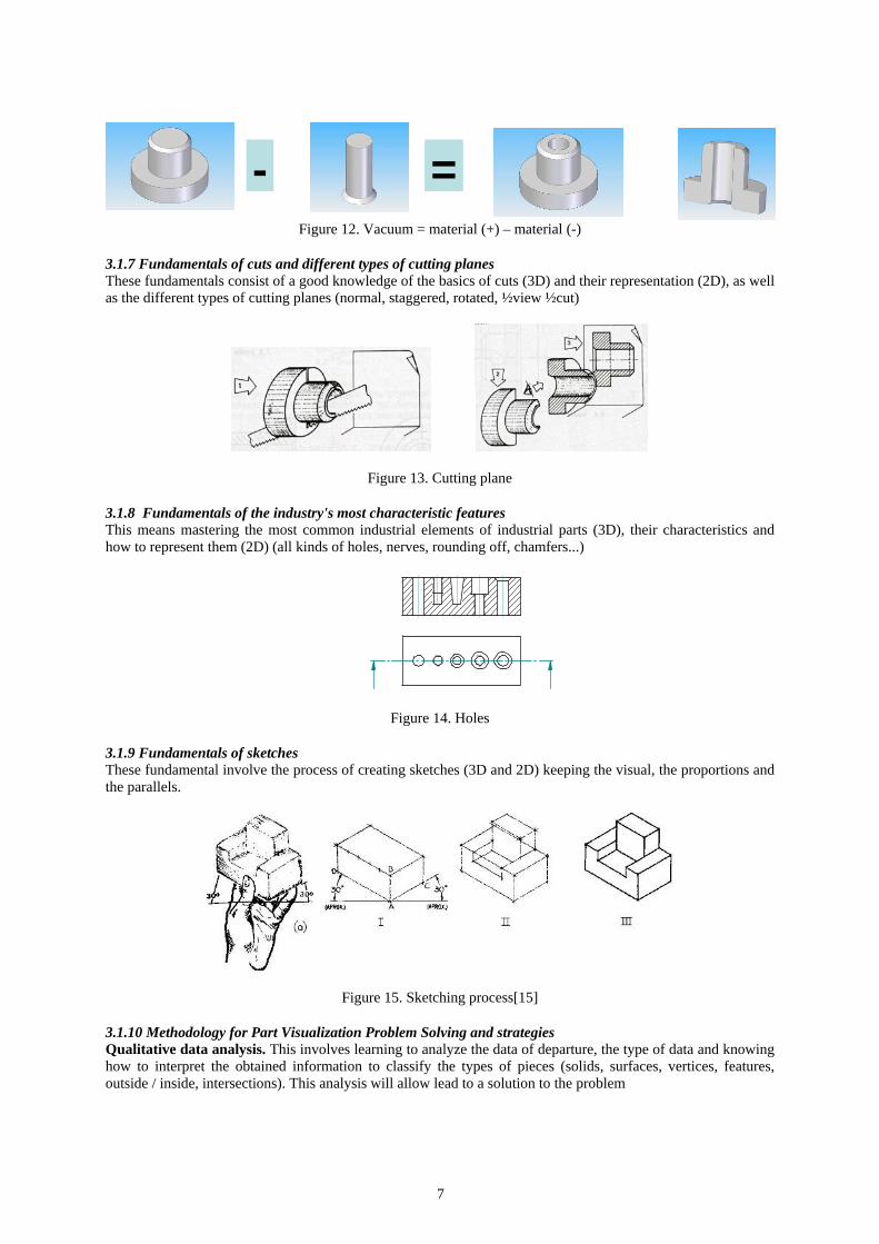
3.1.7 Fundamentals of cuts and different types of cutting planes These fundamentals consist of a good knowledge of the basics of cuts (3D) and their representation (2D), as well as the different types of cutting planes (normal, staggered, rotated, ½view ½cut)
Figure 13. Cutting plane
3.1.8 Fundamentals of the industry's most characteristic features This means mastering the most common industrial elements of industrial parts (3D), their characteristics and how to represent them (2D) (all kinds of holes, nerves, rounding off, chamfers...)
Figure 14. Holes
3.1.9 Fundamentals of sketches These fundamental involve the process of creating sketches (3D and 2D) keeping the visual, the proportions and the parallels.
Figure 15. Sketching process[15]
3.1.10 Methodology for Part Visualization Problem Solving and strategies Qualitative data analysis. This involves learning to analyze the data of departure, the type of data and knowing how to interpret the obtained information to classify the types of pieces (solids, surfaces, vertices, features, outside / inside, intersections). This analysis will allow lead to a solution to the problem
- =
8
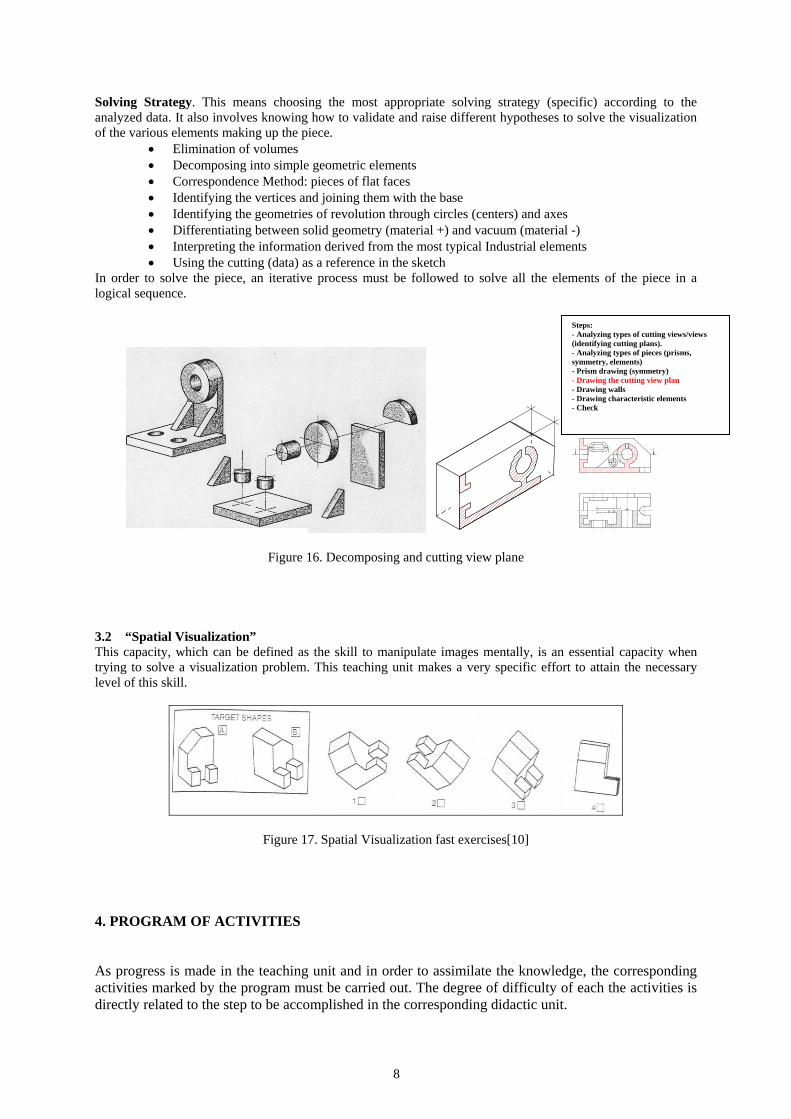
Solving Strategy. This means choosing the most appropriate solving strategy (specific) according to the analyzed data. It also involves knowing how to validate and raise different hypotheses to solve the visualization of the various elements making up the piece.
• Elimination of volumes • Decomposing into simple geometric elements • Correspondence Method: pieces of flat faces • Identifying the vertices and joining them with the base • Identifying the geometries of revolution through circles (centers) and axes • Differentiating between solid geometry (material +) and vacuum (material -) • Interpreting the information derived from the most typical Industrial elements • Using the cutting (data) as a reference in the sketch
In order to solve the piece, an iterative process must be followed to solve all the elements of the piece in a logical sequence.
Figure 16. Decomposing and cutting view plane
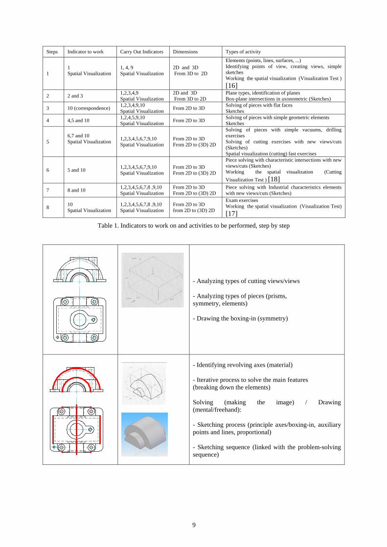
3.2 “Spatial Visualization” This capacity, which can be defined as the skill to manipulate images mentally, is an essential capacity when trying to solve a visualization problem. This teaching unit makes a very specific effort to attain the necessary level of this skill.
Figure 17. Spatial Visualization fast exercises[10]
4. PROGRAM OF ACTIVITIES
As progress is made in the teaching unit and in order to assimilate the knowledge, the corresponding activities marked by the program must be carried out. The degree of difficulty of each the activities is directly related to the step to be accomplished in the corresponding didactic unit.
Pasos:-Analizar tipo de vistas/cortes(identificar planos de corte)-Analizar tipo de pieza (prisma, simetría, elementos )-Dibujar prisma (simetría)-Dibujar plano de corte-Dibujar paredes-Dibujar elementos característicos-Comprobar
CORTE A-A
Steps: - Analyzing types of cutting views/views (identifying cutting plans). - Analyzing types of pieces (prisms, symmetry, elements) - Prism drawing (symmetry) - Drawing the cutting view plan - Drawing walls - Drawing characteristic elements - Check
9
Steps Indicator to work Carry Out Indicators Dimensions Types of activity
1 1 Spatial Visualization
1, 4, 9 Spatial Visualization
2D and 3D From 3D to 2D
Elements (points, lines, surfaces, ...) Identifying points of view, creating views, simple sketches Working the spatial visualization (Visualization Test ) [16]
2 2 and 3 1,2,3,4,9 Spatial Visualization
2D and 3D From 3D to 2D
Plane types, identification of planes Box-plane intersections in axonometric (Sketches)
3 10 (correspondence) 1,2,3,4,9,10 Spatial Visualization From 2D to 3D Solving of pieces with flat faces
Sketches
4 4,5 and 10 1,2,4,5,9,10 Spatial Visualization From 2D to 3D Solving of pieces with simple geometric elements
Sketches
5 6,7 and 10 Spatial Visualization
1,2,3,4,5,6,7,9,10 Spatial Visualization
From 2D to 3D From 2D to (3D) 2D
Solving of pieces with simple vacuums, drilling exercises Solving of cutting exercises with new views/cuts (Sketches) Spatial visualization (cutting) fast exercises
6 5 and 10 1,2,3,4,5,6,7,9,10 Spatial Visualization
From 2D to 3D From 2D to (3D) 2D
Piece solving with characteristic intersections with new views/cuts (Sketches) Working the spatial visualization (Cutting Visualization Test ) [18]
7 8 and 10 1,2,3,4,5,6,7,8 ,9,10 Spatial Visualization
From 2D to 3D From 2D to (3D) 2D
Piece solving with Industrial characteristics elements with new views/cuts (Sketches)
8 10 Spatial Visualization
1,2,3,4,5,6,7,8 ,9,10 Spatial Visualization
From 2D to 3D from 2D to (3D) 2D
Exam exercises Working the spatial visualization (Visualization Test) [17]
Table 1. Indicators to work on and activities to be performed, step by step
- Analyzing types of cutting views/views - Analyzing types of pieces (prisms, symmetry, elements) - Drawing the boxing-in (symmetry)
- Identifying revolving axes (material) - Iterative process to solve the main features (breaking down the elements) Solving (making the image) / Drawing (mental/freehand): - Sketching process (principle axes/boxing-in, auxiliary points and lines, proportional) - Sketching sequence (linked with the problem-solving sequence)

10
- Identifying revolving axes (- material) - Breakdown of the analysis (sub-problems) (general-to-detail / left-to-right / top-to-bottom / outside-to-inside)
- Once we have solved the main features we go into the details - the attributes of common features in mechanical components (rib, web, holes, lug, chamfers, …)
Analysis of results (confirmation of the image) : - In agreement with the data
Table 2. Resolution process example
Figure 18. Evaluation of knowledge acquisition when solving visualization problems: the students had to do it by hand despite the formulation and the solution in this case being CAD made

11
5. RESULTS AND CONCLUSIONS Analyzing the results of the Visualization exercises at official examinations, the average (t student) between the group that has used the described method (experimental group) and the rest of the students (control group), which has continued with traditional teaching, is significantly different.
Industrial Engineering 06-07 course
07-08 course
Experimental Group size 46 56
Control Group size 257 279
Table 3 and 4. Group size and exam averages, Industrial Engineering
Chemical Engineering 06-07 course
07-08 course
Experimental Group size 25 25
Control Group size 20 9
Table 5 and 6. Group size and exam averages, Chemical Engineering Some special tests have been performed and recorded individually with some students in both groups. These test show that the experimental group follows a reasonable method of resolution whilst the control group keeps on basing its work on experience and intuition. It was also noted that the less the student has a prior knowledge (typical Chemical Engineering students' profile) the better (s)he works with the new methodology. Besides, a higher attendance to the final exam and a lower demand for of private lessons at the end of the semester were registered in the experimental group.
References [1] Sierra Uria, Egoitz, Master in Engineering Design Graphic Education 2006. Análisis de la asimilación de
la competencia “ver en el espacio” en el ámbito de los estudios de ingeniería. XIII Congreso Universitario de Innovación Educativa en las Enseñanzas Técnica .XIII CUIEET Canarias, Spain. 2005 pp. 30.
[2] Kedmon Hungwe, Thomas Drummer, Sheryl A. Sorby, Paul Charlesworth. Developing 3-D Spatial Visualization Skills for Non-Engineering Students. Journal of Engineering Education, Jul 2000, 63(2), pp. 21-32
[3] Fernando Hernández, Juana María Sancho, Para enseñar no basta con saber la asignatura. 1993 (Ed. Paidós, Barcelona, Spain)
0
0,5
1
1,5
2
2,5
3
3,5
4
4,5
06-07 part ial test 06-07 f inal exam 07-08 part ial test 07-08 f inal exam
INDUSTRIAL ENGINERING
Experimental group Control group
0
1
2
3
4
5
6
06-07 partial test 06-07 final exam 07-08 partial test 07-08 final exam
CHEMICAL ENGINERING
Experimental group Control group

12
[4] Luzzader W.J. y Duff J.M. Fundamentos de dibujo en ingeniería. 1986 (Prentice Hall. Hispanoamericana Mexico)
[5] Garmendia M. Análisis crítico de la enseñanza de visualización en primer ciclo de universidad y propuesta alternativa de orientación constructivista. PhD in Engineering Design Graphic Education, (2004) Basque Country
[6] Guisasola, J., Furió C., Ceberio, M. and Zubimendi, J.L. ¿Es necesaria la enseñanza de contenidos procedimentales en cursos introductorios de física en la universidad? Enseñanza de las Ciencias, extra number, 17-28(2003)
[7] Navarro R.. El dibujo de croquis y la visualización espacial: su aprendizaje y valoración en la formación del ingeniero a través de las nuevas tecnologías. XII Congreso Universitario de Innovación Educativa en las Enseñanzas Técnicas. XII CUIEET 2004 Barcelona, Spain.
[8] Mathewson, J.H. Visual-spatial thinking: An aspect of science overlooked by educators. Science & Education,1999, 83(1), pp. 33-54.
[9] Potter C.S. and Van Der Merwe, E. Percepcion, imagery, visualization and engineering graphics. European Journal of Engineering Education, 2003, VOL 28, nº1, 117-133
[10] Gary R. Bertoline, Eric N. Wiebe Technical Graphics Communication. (third edition). 2003 (Mc Graw Hill)
[11] Vygotsky, L.S. Mind in Society. Cambridge, MA: Harvard University Press(1978). [12] Devon, R., Engle, Foster, Sathianathan, Turner The effect of solid modelling software on 3D visualizations
skills. EngineeringDesign Graphics Journal, 1994,58(2); pp. 4-11. [13] Bertoline G., Wiebe E., Miller C., Mohler J. Dibujo en ingeniería y comunicación gráfica. 1995 (Mc Graw
Hill, mexico) [14] M. Garmendia, J. Guisasola, E. Sierra. First year engineering students’ difficulties in visualization and
drawing tasks. European Journal of Engineering Education, 2007 .Volume 32 Issue 3 [15] Frederick E. Giesecke, Alva Mitchell, Henry Cecil Spencer, Ivan Leroy Hill, Robert Olin Loving, John
Thomas Dygdon “Engineering Graphics” (fourth edition) 1987 (Paramus, NJ, U.S.A., Prentice Hall) [16] Sarah Titus, Eric Horsman. The Visualization Survey. Univ. of Wisconsin-Madison [17] Dr. Claudia Quaiser-Pohl. The Mental Cutting Test "Schnitte "and the Picture Rotation Test-Two New
Measures to Assess Spatial Ability. International Journal of Testing, Volume 3, Issue 3 September 2003 , pages 219 - 231