mf9223 metal forming processes
TRANSCRIPT
www.mechstudent.weebly.com
MF9223 METAL FORMING PROCESSES
UNIT IV POWDER METALLURGY AND SPECIAL FORMING PROCESSES
Overview of P/M technique – Advantages – applications – Powder preform forging – powder rolling – Tooling, process parameters and applications. - Orbital forging – Isothermal forging – Hot and cold isostatic pressing – High speed extrusion – Rubber pad forming – Fine blanking – LASER beam forming
Compiled by
VEERAPANDIAN.K SRV ENGINEERING COLLEGE, VEDARANYAM.
www.mechstudent.weebly.com
POWDER METALLURGY
Powder metallurgy is the manufacturing science of producing solid parts of desired geometry and material from powders. Commonly known as powder metallurgy it may also be referred to as powder processing considering that non metal powders can be involved. Powders are compacted into a certain geometry then heated, (sintered), to solidify the part. The manufacturing advantages and disadvantages as well as the applications for part produced by this method are discussed latter in the design and applications of powder metallurgy section.
The first consideration in powder metallurgy is the powders used for the process. Several different measures are used to quantify the properties of a certain powder. Powders can be pure elements or alloys. A powder might be a mixture of different kinds of powders. It could be a combination of elemental powders, alloy powders, or both elemental and alloy powders together. Material and the method of method of powder production are critical factors in determining the properties of a powder. It should always be remembered when working with powders that the powder itself may be a potential hazard. Some powders may be flammable and/or present health risks to workers. Safety precautions should always be taken when handling or storing powders. Also be sure to follow any regulations regarding the handling, storage, or disposal of powders. Powder selection and processing will depend on cost, desired purity and mechanical properties of finished product. Environmental control is critical in proper storage and handling of powders. Contamination of powder can result in powder degradation and should be avoided. Remember, high surface areas cause powders to react readily with outside materials, oxidation for example, caused by oxygen present in the air.

www.mechstudent.weebly.com
Powder Properties
Powders are finely divided solid particulates. The size and shape of individual particulates is important. Characteristics of a powder can be quantified in several ways. These characteristics are necessary to understand when selecting a powder for an operation. since powder properties will effect processing factors.
Size And Distribution
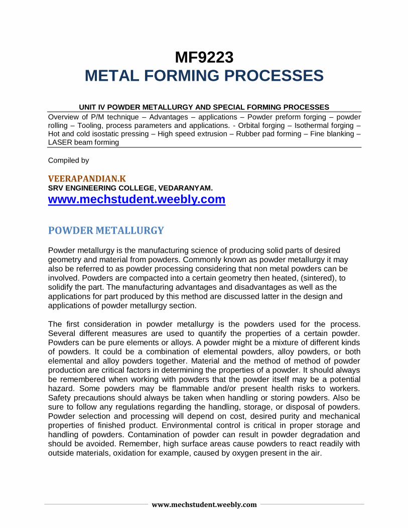
Size of particles is a factor that will effect processing of metal powders. Powders are commonly measured using a series of screens with different sized openings. Each screen is a wire mesh with openings ideally of the same size. Screens for powder measurement are designated according to the number of openings per linear inch, (i.e. 30, 100). Openings per linear inch are the same in the 2 dimensions of the screens surface, therefore the number of openings per square inch is the square of the linear number. A screen with a linear measurement of 100 has 1002 or 10,000 openings per square inch. When determining the size of an opening the size of the screens wire must also be considered. Mesh opening size, (MS), can be determined by MS = 1/MC - WS, where MC is the mesh count, (openings per linear inch), and WS is the thickness of the wire.
www.mechstudent.weebly.com
These screens are stacked one over another with the screen with the largest openings on top. As the stack progresses downward each sequential screen has a smaller opening than the one above it. A powder sample is poured on the top screen. A machine vibrates the stack. Powder particles will fall through the screen openings until they encounter a screen size too small to fit through. Thus, each screen will collect metal powder particles of a certain size range. The sizes and distribution of sizes can then be measured. For example the particles that pass through 90 but not 100 are said to have a size of 90-100, they may also be considered to have a size of 90. With this method, particle size distribution can be measured, usually by weight percent, and quantified. Results can be represented graphically, the size range in which the highest weight percent of particles occur is called the mode size.
This system does have limitations. Imperfect screens can result in variations in the size of openings. Differently shaped particles also effect the accuracy of the powder screening technique. The difficulties involved in manufacturing screens increase as the number of openings per inch increases. For this reason powder particle size measurement using screens is limited to a lower range of about 400 opening per linear inch. Very small powder particles tend to agglomerate or stick together, which would make the metal powder screening method ineffective at extremely low ranges anyway.
There are several other methods by which particle size can be determined. Particles are suspended in a liquid medium and can be measured by light scattering techniques or by electrical sensors. Measurements can be made with a microscope. Other types of optical analysis may be used. X-ray measuring techniques are available. Sedimentation is also a method to measure powder particle size and distribution. Sedimentation determines size by measuring the sinking of a particles in a liquid.
www.mechstudent.weebly.com
Particle Structure
The structure or shape, of particles is a major factor in a powder processing operation. Material and method of powder production are the main variables determining powder shape. Particles of a certain powder may have similar shapes but no particle shapes are exactly the same. Hence, there will exist a shape distribution within a powder. Different types of powders combined together may also have significant differences in particle shape, which will show in the shape distribution.
Particle shape plays a large roll in powder density and flow characteristics, it is also a major factor in pressing and sintering. There are several types of basic powder particle shapes. These are ideal shapes, particles in reality are imperfect and may exhibit characteristics of more than one shape type.
Porosity
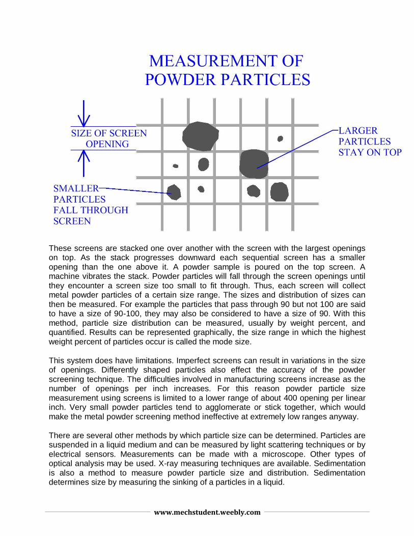
Pores or space within the powder is in a large part determined by particle shape, (and size), since the shape dictates how particles will contact each other. Spaces that exist between particles of a powder and are open to the outside are called open pores. These spaces expose external surfaces of powder particles.
www.mechstudent.weebly.com
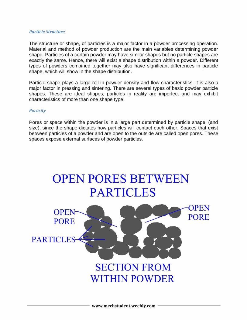
During compaction of powder these spaces are eliminated. If a certain amount of this space remains after processing, it will result in porosity in the part. These open pores are permeable to the atmosphere. They are also permeable to fluids in general, such as liquid lubricants, water, or melted polymers, provided that the porous regions are interconnected and not isolated. The other type of vacancy that exists in a powder material is called a closed pore. These pores are not open to the outside atmosphere. Closed pores can develop during the pressing and sintering process if an open pore region becomes closed off. Another type of closed pore exists within the material of the powder particle itself. Theoretically if all the open pores, and closed pores were eliminated the density would be that of the fully dense material.
Figure:324
Friction And Flow Of Powders
The ability of a powder to flow will differ depending upon the properties of that powder. Material flow will involve movement of particles over one another. Factors determining the ability of a particular powder to flow are particle size, particle size distribution, particle structure, particle surface, presence of moisture, material(s), and lubrication. Characteristics that decrease inter-particle friction will tend to increase a powder's ability to flow.
Better ability to flow is usually preferred for a manufacturing powder. More ability to flow results in faster powder flow rates. Faster rates will decrease die filling time, providing a higher production rate. Powder flow is important during the compaction of the part. Powder with poor flow characteristics may result in uneven compaction, meaning
www.mechstudent.weebly.com
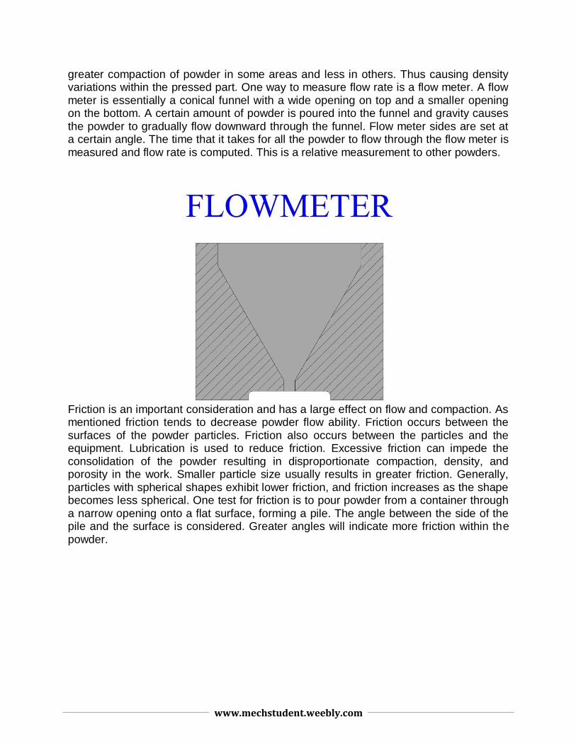
greater compaction of powder in some areas and less in others. Thus causing density variations within the pressed part. One way to measure flow rate is a flow meter. A flow meter is essentially a conical funnel with a wide opening on top and a smaller opening on the bottom. A certain amount of powder is poured into the funnel and gravity causes the powder to gradually flow downward through the funnel. Flow meter sides are set at a certain angle. The time that it takes for all the powder to flow through the flow meter is measured and flow rate is computed. This is a relative measurement to other powders.
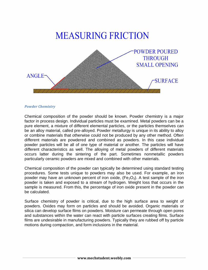
Friction is an important consideration and has a large effect on flow and compaction. As mentioned friction tends to decrease powder flow ability. Friction occurs between the surfaces of the powder particles. Friction also occurs between the particles and the equipment. Lubrication is used to reduce friction. Excessive friction can impede the consolidation of the powder resulting in disproportionate compaction, density, and porosity in the work. Smaller particle size usually results in greater friction. Generally, particles with spherical shapes exhibit lower friction, and friction increases as the shape becomes less spherical. One test for friction is to pour powder from a container through a narrow opening onto a flat surface, forming a pile. The angle between the side of the pile and the surface is considered. Greater angles will indicate more friction within the powder.
www.mechstudent.weebly.com
Powder Chemistry
Chemical composition of the powder should be known. Powder chemistry is a major factor in process design. Individual particles must be examined. Metal powders can be a pure element, a mixture of different elemental particles, or the particles themselves can be an alloy material, called pre-alloyed. Powder metallurgy is unique in its ability to alloy or combine materials that otherwise could not be produced by any other method. Often different materials are powdered and combined as powders. In this case individual powder particles will be all of one type of material or another. The particles will have different characteristics as well. The alloying of metal powders of different materials occurs latter during the sintering of the part. Sometimes nonmetallic powders particularly ceramic powders are mixed and combined with other materials.
Chemical composition of the powder can typically be determined using standard testing procedures. Some tests unique to powders may also be used. For example, an iron powder may have an unknown percent of iron oxide, (Fe2O3). A test sample of the iron powder is taken and exposed to a stream of hydrogen. Weight loss that occurs in the sample is measured. From this, the percentage of iron oxide present in the powder can be calculated.
Surface chemistry of powder is critical, due to the high surface area to weight of powders. Oxides may form on particles and should be avoided. Organic materials or silica can develop surface films on powders. Moisture can permeate through open pores and substances within the water can react with particle surfaces creating films. Surface films are undesirable in manufacturing powders. Typically they are rubbed off by particle motions during compaction, and form inclusions in the material.
www.mechstudent.weebly.com
Surface Area
Surface is measured by considering the combined surface area of all the particles and relating that to the volume of powder, (usually cm2/g). Powders have an extremely high surface area to volume ratio. Surface area to volume increases as particle size decreases. Particle shape also is a factor in surface area. The higher the surface area the more activity that will occur during sintering. There are advantages and disadvantages to increased surface area of powders. Increased surface area will increase the area for oxides and other surface films to develop. Also agglomeration, or the sticking together of powder particles tends to occur in smaller sized particles. Smaller particles are advantageous in that they provide more uniform material distribution in the process, and better mechanical properties in the product.
Bulk Density
Bulk density is the density of the powder in its loose, uncompressed form. A container of known volume is filled with the powder. The powder is then weighed, and the density is determined, usually expressed in g/cm3. Major factors determining bulk density of a powder are particle size, particle size distribution, and particle shape.
True density of a material would be the density of the mass if the powder particles were melted and formed into a single piece. During the compression stage the particles are reshuffled, becoming generally closer together as inter-particular pores are eliminated. As the powder is compressed its density increases. In order to process a powder to its true density all porosity open and closed must be eliminated. The difference between open and closed pores is discussed above under porosity. Conventional powder processing does not achieve elimination of all porosity. Several special powder processes, discussed latter, attempt to produce parts closer to 100% true density.
Packing factor is the bulk density of the powder divided by the true density of the material. Common packing factors might be .5 or .7. Porosity indicates the amount of empty space within the material. Porosity is expressed as the percentage of total volume that is empty.
Compressability, Compactability, And Sinterability
Compressability indicates the relative ability for a powder to compress. For example, lubricants can improve compressability. Compactability is not the same as compressability. Compactability is a measurement of the structural strength of a compacted, unsintered powder, (called a green compact). Binders, for example, can increase the compactability of a powder. Sinterability is the ability of powder particles of the green compact, to bond together when heated during the sintering process.
www.mechstudent.weebly.com
Sinterability is dependant to a large extent on surface characteristics of the powder particles.
Powder Production
The production of powder of different materials is an essential first step in powder metallurgy. Method of production is important, different powder materials are produced differently. Particle structure characteristics such as size and shape will also be dependent on production method. Some materials are produced with more than one technique. Industrial manufacturers that produce powders are usually different than those involved in powder part manufacture. Atomization is the most popular method of powder production. Other methods include reduction, carbonyl decomposition, precipitation from solution, mechanical, condensation, and electrolic deposition.
Mixing Of Powders
Before processing it is desirable to create a homogeneous or uniform distribution of all the different material constituents within the powder mass. Uniform distribution of powder particles is important in helping to obtain uniform density within the processed part. Constituents within a powder material ready for processing can include, powders from one or more materials, lubricants, deflocculates, and binders. Lubricants improve flow characteristics of powder particles, deflocculates help stop agglomeration of particles, and binders help improve compactability.
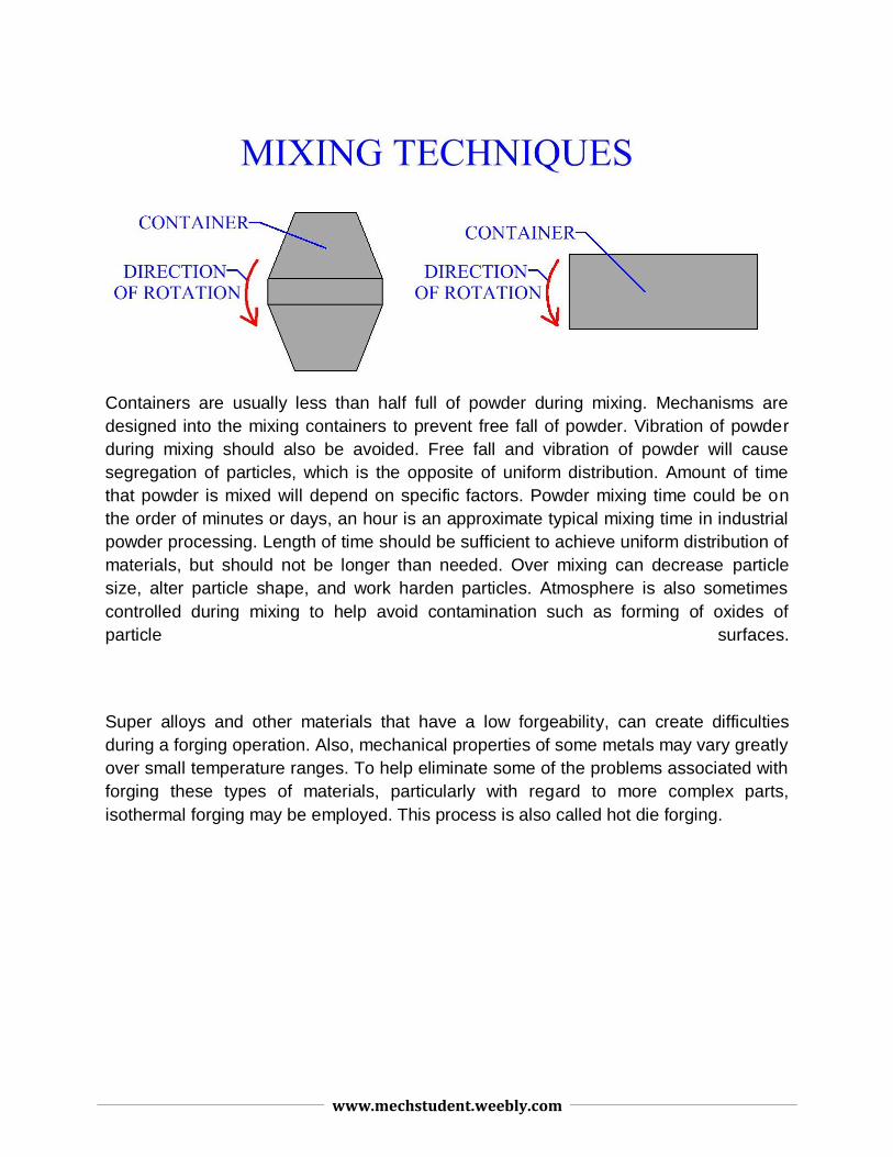
Blending is different from mixing as it is in reference to uniformly distributing particles of the same material. Blending achieves uniform size and shape distribution of particles within a powder. Mixing refers to combining and homogeneously distributing particles of different materials. Individual powder materials are often blended first then mixed with other powders. Mixing is performed by a variety of mechanical methods. Common techniques are rotating containers such as drums or cones, and stirring mechanisms.
www.mechstudent.weebly.com
Containers are usually less than half full of powder during mixing. Mechanisms are
designed into the mixing containers to prevent free fall of powder. Vibration of powder
during mixing should also be avoided. Free fall and vibration of powder will cause
segregation of particles, which is the opposite of uniform distribution. Amount of time
that powder is mixed will depend on specific factors. Powder mixing time could be on
the order of minutes or days, an hour is an approximate typical mixing time in industrial
powder processing. Length of time should be sufficient to achieve uniform distribution of
materials, but should not be longer than needed. Over mixing can decrease particle
size, alter particle shape, and work harden particles. Atmosphere is also sometimes
controlled during mixing to help avoid contamination such as forming of oxides of
particle surfaces.
Super alloys and other materials that have a low forgeability, can create difficulties
during a forging operation. Also, mechanical properties of some metals may vary greatly
over small temperature ranges. To help eliminate some of the problems associated with
forging these types of materials, particularly with regard to more complex parts,
isothermal forging may be employed. This process is also called hot die forging.
www.mechstudent.weebly.com
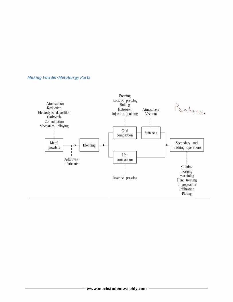
Making Powder-Metallurgy Parts
www.mechstudent.weebly.com
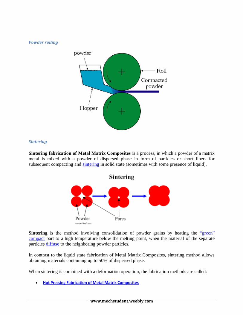
Powder rolling
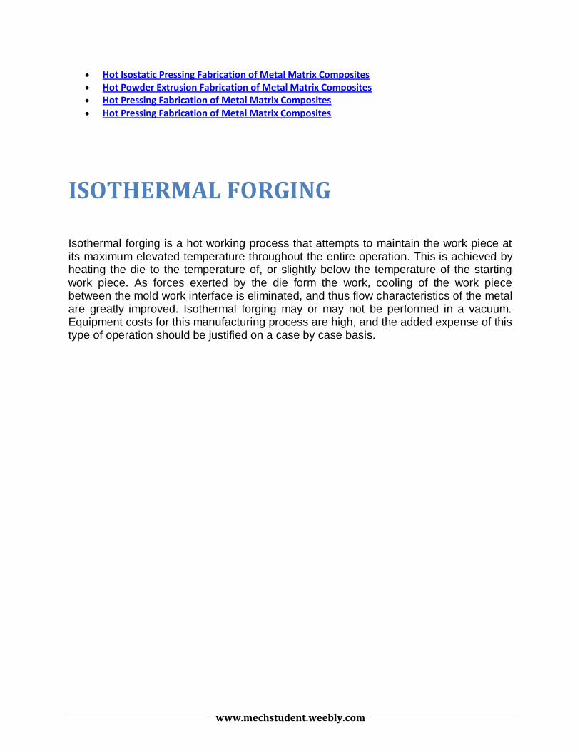
Sintering
Sintering fabrication of Metal Matrix Composites is a process, in which a powder of a matrix
metal is mixed with a powder of dispersed phase in form of particles or short fibers for
subsequent compacting and sintering in solid state (sometimes with some presence of liquid).
Sintering is the method involving consolidation of powder grains by heating the “green”
compact part to a high temperature below the melting point, when the material of the separate
particles diffuse to the neighboring powder particles.
In contrast to the liquid state fabrication of Metal Matrix Composites, sintering method allows
obtaining materials containing up to 50% of dispersed phase.
When sintering is combined with a deformation operation, the fabrication methods are called:
Hot Pressing Fabrication of Metal Matrix Composites
www.mechstudent.weebly.com
Hot Isostatic Pressing Fabrication of Metal Matrix Composites Hot Powder Extrusion Fabrication of Metal Matrix Composites Hot Pressing Fabrication of Metal Matrix Composites Hot Pressing Fabrication of Metal Matrix Composites
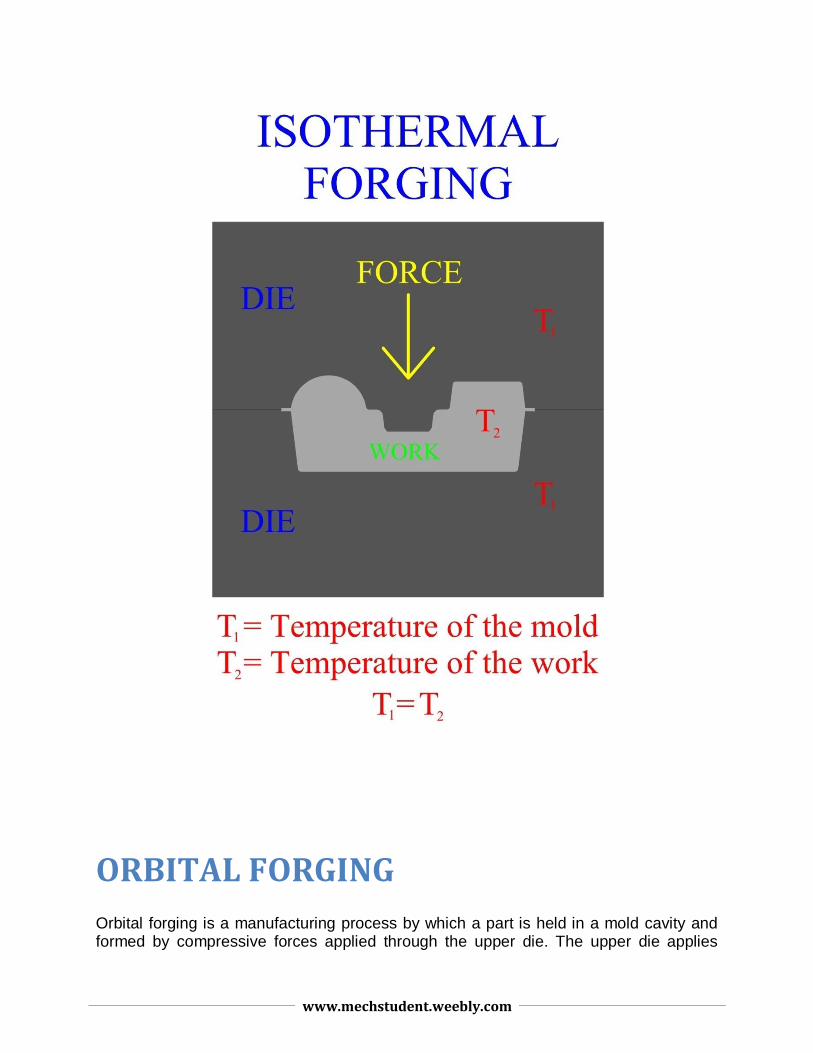
ISOTHERMAL FORGING
Isothermal forging is a hot working process that attempts to maintain the work piece at its maximum elevated temperature throughout the entire operation. This is achieved by heating the die to the temperature of, or slightly below the temperature of the starting work piece. As forces exerted by the die form the work, cooling of the work piece between the mold work interface is eliminated, and thus flow characteristics of the metal are greatly improved. Isothermal forging may or may not be performed in a vacuum. Equipment costs for this manufacturing process are high, and the added expense of this type of operation should be justified on a case by case basis.
www.mechstudent.weebly.com
ORBITAL FORGING
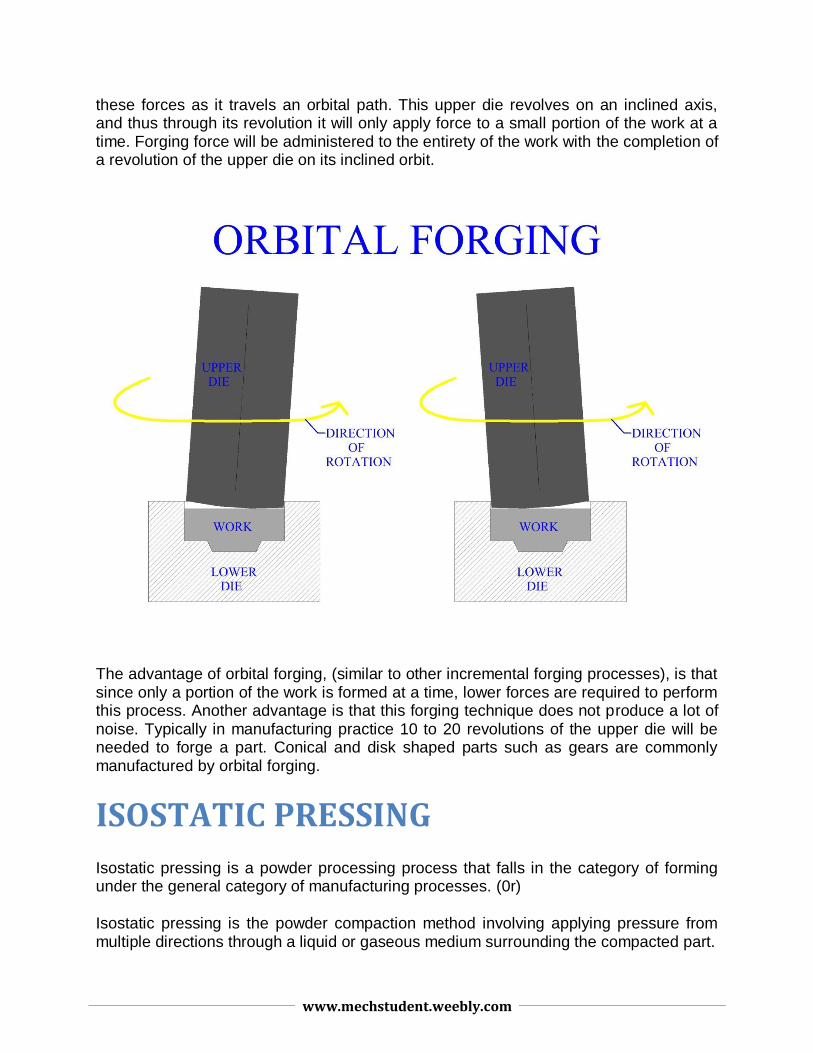
Orbital forging is a manufacturing process by which a part is held in a mold cavity and formed by compressive forces applied through the upper die. The upper die applies
www.mechstudent.weebly.com
these forces as it travels an orbital path. This upper die revolves on an inclined axis, and thus through its revolution it will only apply force to a small portion of the work at a time. Forging force will be administered to the entirety of the work with the completion of a revolution of the upper die on its inclined orbit.
The advantage of orbital forging, (similar to other incremental forging processes), is that since only a portion of the work is formed at a time, lower forces are required to perform this process. Another advantage is that this forging technique does not produce a lot of noise. Typically in manufacturing practice 10 to 20 revolutions of the upper die will be needed to forge a part. Conical and disk shaped parts such as gears are commonly manufactured by orbital forging.
ISOSTATIC PRESSING
Isostatic pressing is a powder processing process that falls in the category of forming under the general category of manufacturing processes. (0r)
Isostatic pressing is the powder compaction method involving applying pressure from multiple directions through a liquid or gaseous medium surrounding the compacted part.
www.mechstudent.weebly.com
There are 2 types of isostatic pressing processes:
Hot isostatic pressing (HIP), where components are loaded into a furnace and then placed in a pressure vessel so that heat and pressure can be applied simultaneously .
Cold isostatic pressing (CIP), where powder is sealed in a flexible mould and is then subjected to a uniform hydrostatic pressure without heating.
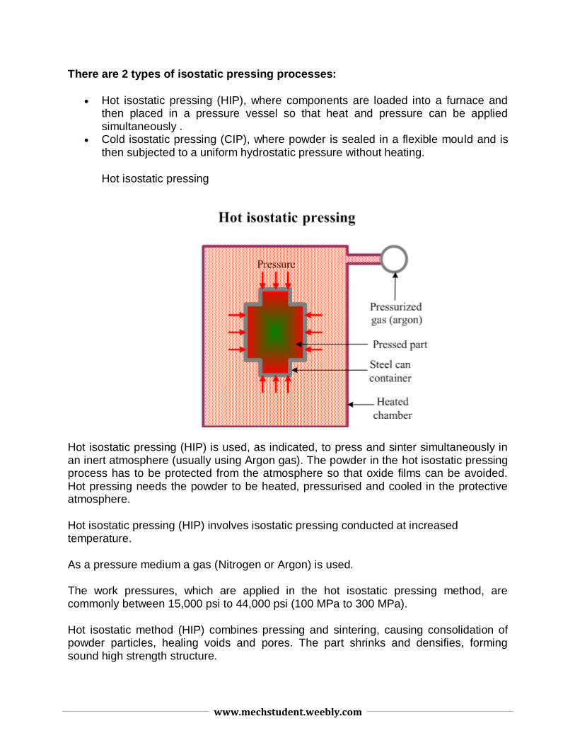
Hot isostatic pressing
Hot isostatic pressing (HIP) is used, as indicated, to press and sinter simultaneously in an inert atmosphere (usually using Argon gas). The powder in the hot isostatic pressing process has to be protected from the atmosphere so that oxide films can be avoided. Hot pressing needs the powder to be heated, pressurised and cooled in the protective atmosphere.
Hot isostatic pressing (HIP) involves isostatic pressing conducted at increased temperature.
As a pressure medium a gas (Nitrogen or Argon) is used.
The work pressures, which are applied in the hot isostatic pressing method, are commonly between 15,000 psi to 44,000 psi (100 MPa to 300 MPa).
Hot isostatic method (HIP) combines pressing and sintering, causing consolidation of powder particles, healing voids and pores. The part shrinks and densifies, forming sound high strength structure.
www.mechstudent.weebly.com
Cans made of stainless steel, or mild steel are used in the method.
The method may be used without a mold. In this case the part is first compacted by cold isostatic pressing method, and then it is sintered in order to close the interconnecting porosity. The sintered (but still porous) part is then pressed isostatically at high temperature without any can (mold).
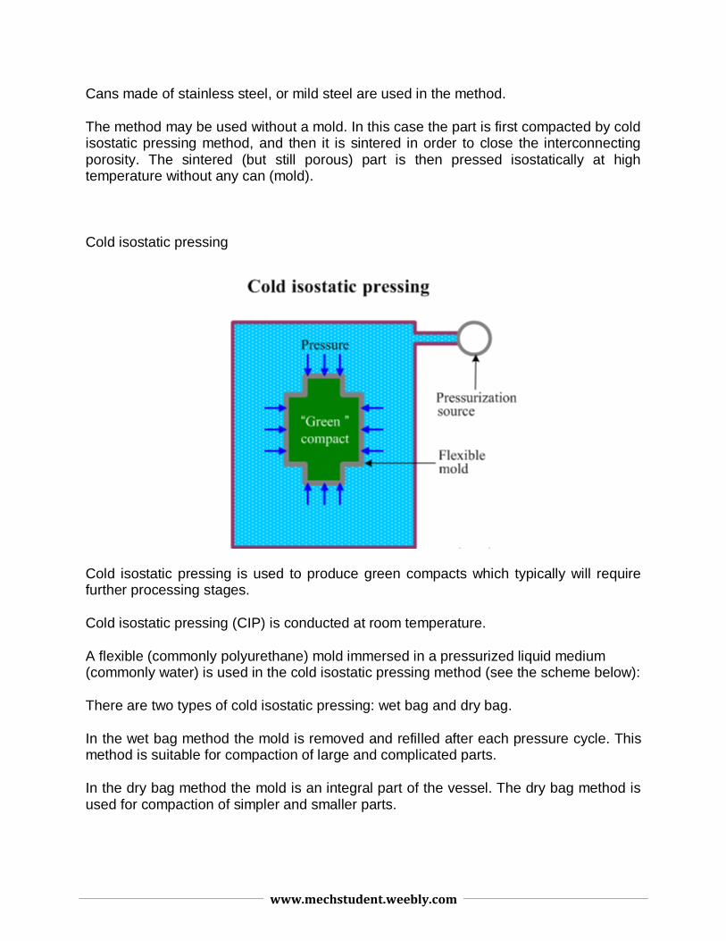
Cold isostatic pressing
Cold isostatic pressing is used to produce green compacts which typically will require further processing stages.
Cold isostatic pressing (CIP) is conducted at room temperature.
A flexible (commonly polyurethane) mold immersed in a pressurized liquid medium (commonly water) is used in the cold isostatic pressing method (see the scheme below):
There are two types of cold isostatic pressing: wet bag and dry bag.
In the wet bag method the mold is removed and refilled after each pressure cycle. This method is suitable for compaction of large and complicated parts.
In the dry bag method the mold is an integral part of the vessel. The dry bag method is used for compaction of simpler and smaller parts.
www.mechstudent.weebly.com
The cold isostatic pressing (CIP) method has the following advantages as compared to the die cold pressing method:
better uniformity of compaction;
more complex forms (for example long thin-walled tubes) may be compacted;
Both processes are expensive from an operating cost perspective but HIP should be considered a very expensive option, the need for a protective environment and the slow cycle time of the process leads to inevitable cost implications. On the positive side there is 100% materials utilisation and the process is reasonably flexible.
The finished products can be produced in solid 3D shapes, mostly utilising metal or ceramic composites, and have relatively low or no porosity. There can be some distortion when producing high aspect ratio components.
One method of producing a finished component using HIP is to fill a formed container with powder, after which the container is evacuated of all gas and is sealed. The container is then placed inside a furnace inside the pressure chamber and the isostatic pressure (utilising an inert gas) and heat is applied.The component using this method takes the shape of the container.
An alternative method is to subject pre-formed components to temperature and pressure as a finishing process that sinters the powder to higher density components.
Note: Isostatic pressure is pressure that is applied from all directions simultaneously.
The process because of the operational costs is normally reserved for the production of high value components that can bear the associated production costs.
www.mechstudent.weebly.com
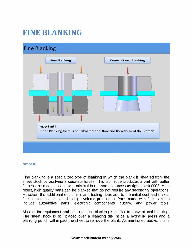
FINE BLANKING
process
Fine blanking is a specialized type of blanking in which the blank is sheared from the sheet stock by applying 3 separate forces. This technique produces a part with better flatness, a smoother edge with minimal burrs, and tolerances as tight as ±0.0003. As a result, high quality parts can be blanked that do not require any secondary operations. However, the additional equipment and tooling does add to the initial cost and makes fine blanking better suited to high volume production. Parts made with fine blanking include automotive parts, electronic components, cutlery, and power tools. Most of the equipment and setup for fine blanking is similar to conventional blanking. The sheet stock is still placed over a blanking die inside a hydraulic press and a blanking punch will impact the sheet to remove the blank. As mentioned above, this is
www.mechstudent.weebly.com
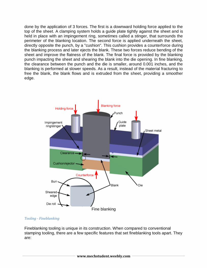
done by the application of 3 forces. The first is a downward holding force applied to the top of the sheet. A clamping system holds a guide plate tightly against the sheet and is held in place with an impingement ring, sometimes called a stinger, that surrounds the perimeter of the blanking location. The second force is applied underneath the sheet, directly opposite the punch, by a "cushion". This cushion provides a counterforce during the blanking process and later ejects the blank. These two forces reduce bending of the sheet and improve the flatness of the blank. The final force is provided by the blanking punch impacting the sheet and shearing the blank into the die opening. In fine blanking, the clearance between the punch and the die is smaller, around 0.001 inches, and the blanking is performed at slower speeds. As a result, instead of the material fracturing to free the blank, the blank flows and is extruded from the sheet, providing a smoother edge.
Fine blanking
Tooling - Fineblanking
Fineblanking tooling is unique in its construction. When compared to conventional stamping tooling, there are a few specific features that set fineblanking tools apart. They are:
www.mechstudent.weebly.com
V-ring (also called impingement ring) Close punch-die clearance Straight (not tapered) die cavity Radiused cutting edges Tooling Construction
V-ring: The V-ring is a raised V-shaped ridge usually on the stinger plate that has the same contour as the blanking punch and is located close to it, roughly a distance equal to 50% of material thickness. In some cases the V-ring is placed on the die plate, sometimes on both the die and the stinger plate, and at times no V-ring is used.
In the initial stage of the fineblanking cycle, the V-ring is pressed into the material to prevent lateral movement of the material in the piercing and blanking operations. The V-ring also ensures that enough material is packed into the die cavity to create fully sheared, straight edges.
Close punch-die clearance:
This is another important feature of fineblanking tooling, which enables the unique characteristics of fineblanked parts to be created. Generally the clearance between punch and die is 0.5% of material thickness - per side. In some cases, depending on the material and application, zero clearance between punch and die is used. The minimal punch-die clearance is the key to obtaining the fully sheared edges that fineblanked parts are noted for. This compares with a typical clearance of 10% of material thickness per side for conventional stamping tools.
Straight die-cavity:
The die-cavity in a fineblanking tool is straight - not tapered. This helps ensure the cleanly sheared edges and results in cut edges that are tapered approximately only 0.5°. Such a minimal taper enables tight dimensional control through the full thickness of the piece part.
The straight die cavity also ensures that after the die plate is ground during regular die maintenance, the size of the die cavity does not grow (as it would if the die cavity was tapered). This ensures that the parts produced in every production run will maintain the same nominal dimensions as when the part was first made.
Radiused cutting edges: Fineblanking is as much an extrusion process as a stamping process. The cutting
www.mechstudent.weebly.com
edges of the die cavity are not sharp - they are radiused. This allows the metal to flow into the die cavity.
Tool Construction:
Fineblanking tools are compound dies, meaning that the part is ejected out of the die cavity. Most fineblanking dies are single station dies, with all features created at one time with a single stroke of the press. Parts made in a single station tool have extremely consistent relationships between features. The use of progressive fineblanking dies is increasing rapidly, in an effort to provide more and more complex features on parts right out of the tool - eliminating secondary operations and enhancing design possibilities.
Because of the extremely close punch and die clearances and the pressures inherent in the process, fineblanking tools must be produced with very tight fit among all tool components.
There are two types of fineblanking tools: sliding punch and fixed punch. Generally, sliding punch tools are used for smaller and less complex parts, while fixed punch tools are used for larger and more complex parts. Sliding punch tools are less expensive to build, set-up, and maintain, but are not as rigid as fixed punch tools - and cannot be used in every application.
RUBBER PAD FORMING
www.mechstudent.weebly.com
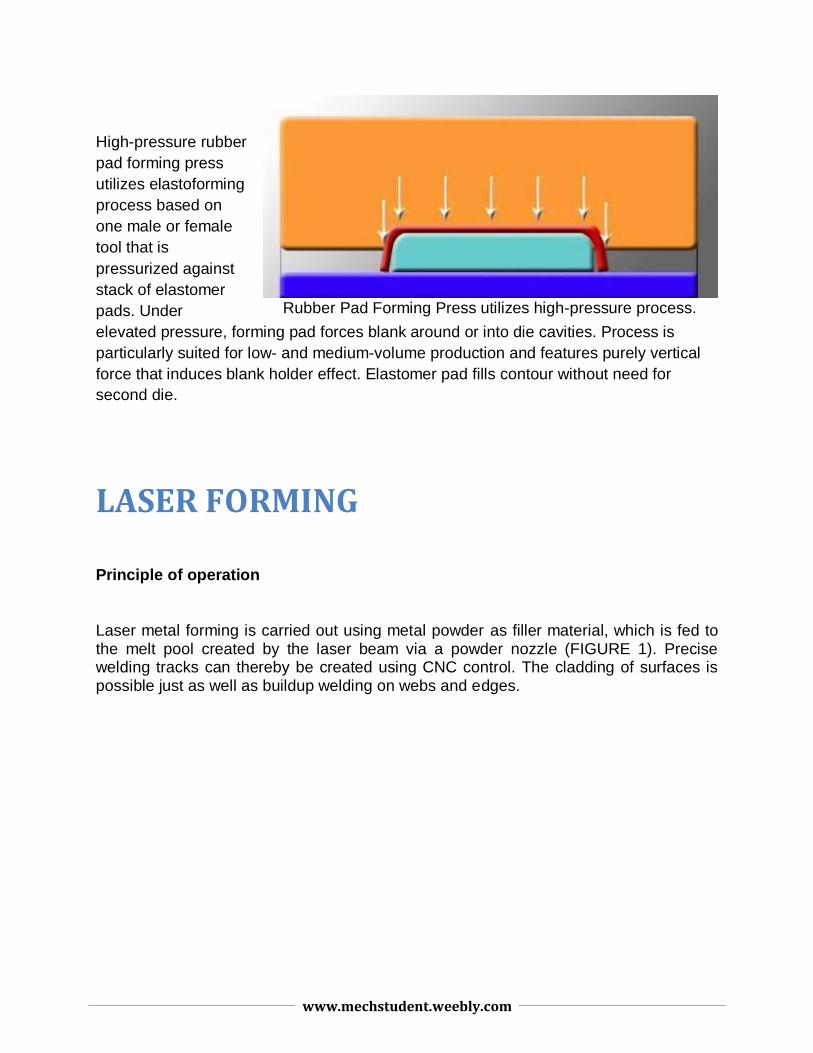
High-pressure rubber
pad forming press
utilizes elastoforming
process based on
one male or female
tool that is
pressurized against
stack of elastomer
pads. Under
elevated pressure, forming pad forces blank around or into die cavities. Process is
particularly suited for low- and medium-volume production and features purely vertical
force that induces blank holder effect. Elastomer pad fills contour without need for
second die.
LASER FORMING
Principle of operation
Laser metal forming is carried out using metal powder as filler material, which is fed to the melt pool created by the laser beam via a powder nozzle (FIGURE 1). Precise welding tracks can thereby be created using CNC control. The cladding of surfaces is possible just as well as buildup welding on webs and edges.
Rubber Pad Forming Press utilizes high-pressure process.

www.mechstudent.weebly.com
FIGURE 1. The principle of laser metal forming: The laser metal forming takes place using metal powder as a filler, which is fed to the melting point created by the laser beam via a powder nozzle.
A powder feeder from Sulzer Metco is used to guarantee a constant and homogeneous flow of the metal powder. The powder is transported in adjustable quantity to the powder nozzle in a gas stream, whereby the inert carrier gas also serves as the shielding gas for the welding process.
Using a suitable powder nozzle, it is even possible to process titanium, which normally reacts very strongly to oxygen. In addition, as almost any material can be atomized, it is also possible to use the laser cladding technique with special materials that are not available as standard powders.
Laser forming has become a viable process for the shaping of metallic
components, as a means of rapid prototyping and of adjusting and aligning. The laser
forming process is of significant value to industries that previously relied on expensive
stamping dies and presses for prototype evaluations, relevant industry sectors include
www.mechstudent.weebly.com
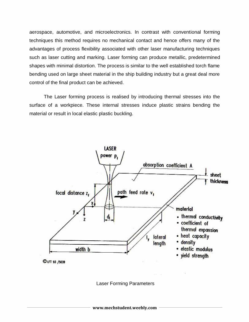
aerospace, automotive, and microelectronics. In contrast with conventional forming
techniques this method requires no mechanical contact and hence offers many of the
advantages of process flexibility associated with other laser manufacturing techniques
such as laser cutting and marking. Laser forming can produce metallic, predetermined
shapes with minimal distortion. The process is similar to the well established torch flame
bending used on large sheet material in the ship building industry but a great deal more
control of the final product can be achieved.
The Laser forming process is realised by introducing thermal stresses into the
surface of a workpiece. These internal stresses induce plastic strains bending the
material or result in local elastic plastic buckling.
Laser Forming Parameters
www.mechstudent.weebly.com
www.mechstudent.weebly.com
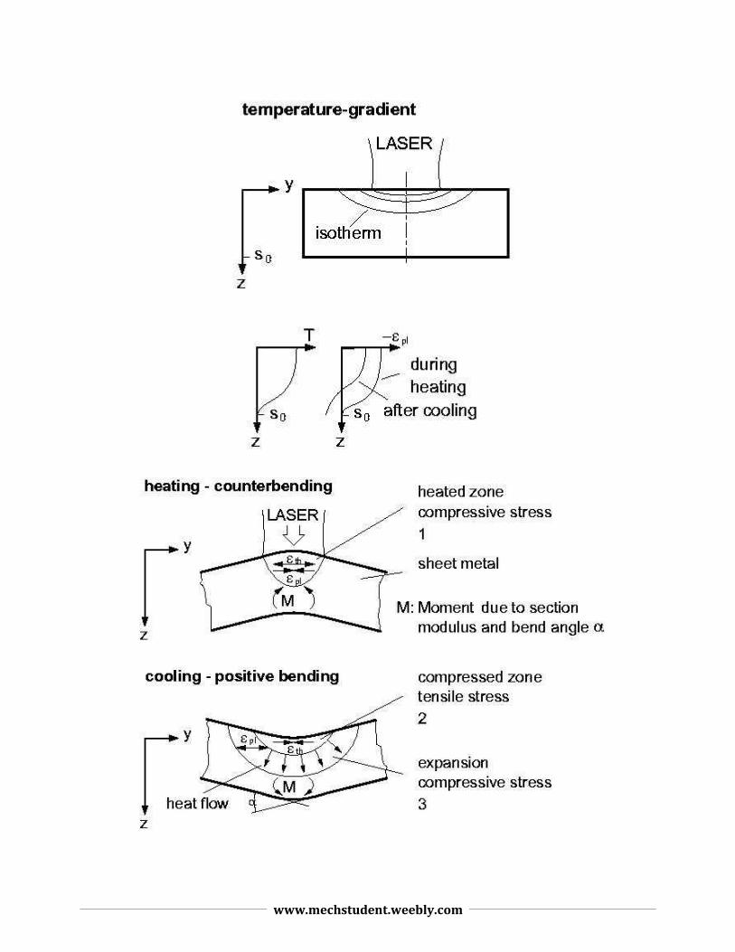
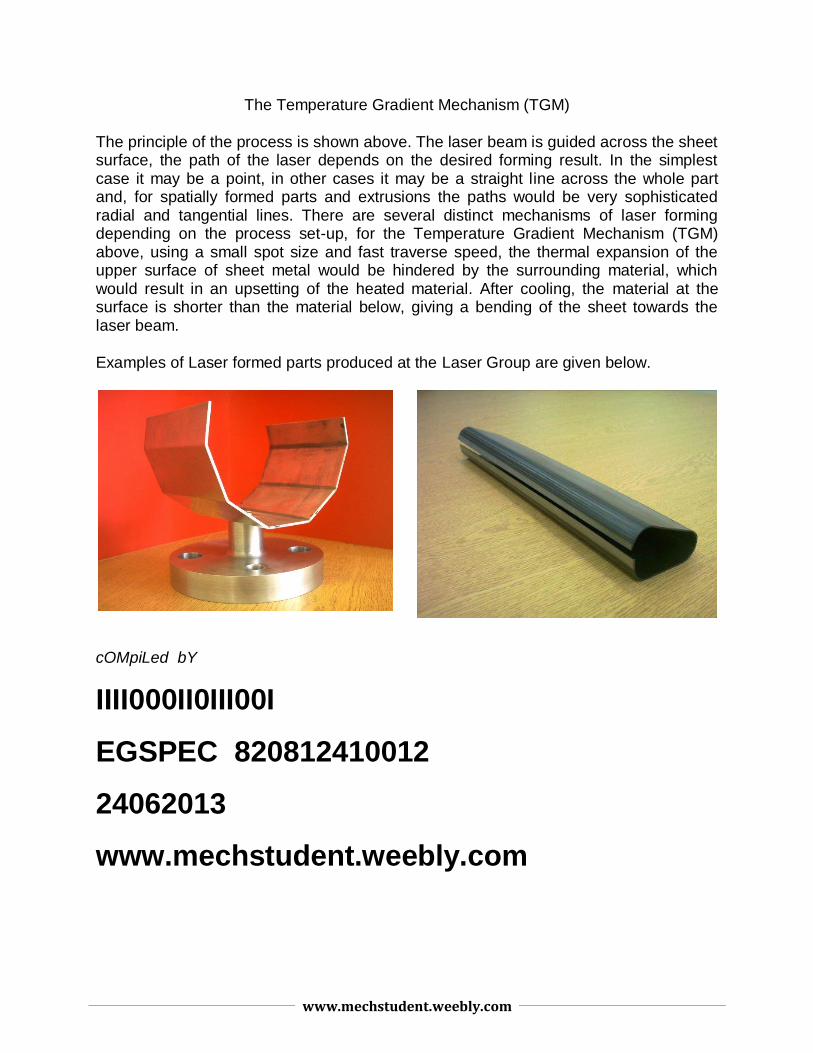
The Temperature Gradient Mechanism (TGM)
The principle of the process is shown above. The laser beam is guided across the sheet surface, the path of the laser depends on the desired forming result. In the simplest case it may be a point, in other cases it may be a straight line across the whole part and, for spatially formed parts and extrusions the paths would be very sophisticated radial and tangential lines. There are several distinct mechanisms of laser forming depending on the process set-up, for the Temperature Gradient Mechanism (TGM) above, using a small spot size and fast traverse speed, the thermal expansion of the upper surface of sheet metal would be hindered by the surrounding material, which would result in an upsetting of the heated material. After cooling, the material at the surface is shorter than the material below, giving a bending of the sheet towards the laser beam.
Examples of Laser formed parts produced at the Laser Group are given below.
cOMpiLed bY
IIII000II0III00I
EGSPEC 820812410012
24062013
www.mechstudent.weebly.com