mitigation of scc susceptible dmw main circulation piping … · © ringhals ab mitigation of scc...
TRANSCRIPT
© Ringhals AB
MITIGATION OF SCC SUSCEPTIBLE DMW MAIN CIRCULATION PIPING WELDS BY INLAY
WELDING
Background, repair and consequent inspection demands
1
2017-05-23

© Ringhals AB 2
Surge nozzle -pipe welds
Spray nozzle-pipe weld
Safety & relief nozzle-pipe welds
RV nozzle-pipe weld
CRDM motor housing
CRDM nozzles to RV head welds
Instrument nozzles
Core support block
Monitor tube
Head vent pipe Heat transfer tubing
Tubesheet (TS) cladding
Tube-TS cladding weld
Partition plate & welds
Primary nozzle closure
rings & welds
Bottom channel head drain tube & welds
Instrument nozzles
Heater sleeves
Instrument nozzles
*After Gourdin/Hernadez, IAEA Technical Meeting on Strategies and Tools for Predictive Maintenance, Daya Bay 2004

© Ringhals AB
BACKGROUND Well known and reported incidents in Ringhals 3 and 4
as well as VC Summers and Tsuruga 2 PWSCC in Alloy 82/182 Defects mainly axially oriented Limited reactor safety influence but a breach of the RCPB Many of the incidents in the western NPPs are thought to be
coupled to repairs and/or poor workmanship during manufacturing The first is sometimes available through manufacturing
documentation, the latter is not (!)
3
From Gutti Rao et.al. Proceeding of Fontevraud 5 p. 29-ff

© Ringhals AB 4
During walk down at VC Summers NPP, leakage was noted by means of Boron oxide Defect was confined in
the nickel based weld metal connecting the RPV-nozzle to the RCS-pipe on the A-hot leg Similar indication has
been seen at Ringhals (Unit 3 and 4) and at Salem

© Ringhals AB
During outages in 2000, defect interpreted as being embedded was reported in the DMW connecting the Main Circulation Loops with the RPV outlet nozzles of Ringhals unit 3 Fitness for service analysis to allow for re-start
Later in 2000, more indication was found in the same area for the sister plant Ringhals 4 Difference: the defects were now in one case interpreted as being surface
breaking
RINGHALS CASE:
5

© Ringhals AB 6
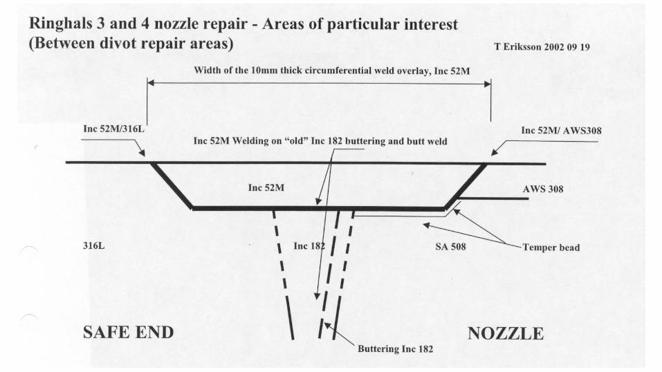
Weld and weld buttering is built up by A182, Base metals are A508 forging and SS safe end Qualified Procedures were used Detection criteria for UT 6mm x 18mm for ET 1mm x 6mm
Tolerances:
± 3 mm depth, ± 13 mm length

© Ringhals AB
INSPECTION RESULTS UNIT 3 First inspection with qualified system Two axial indications detected with UT not with ET and reported as not being surface
breaking 4-6 mm deep, 16 mm wide Deepest point reported as 9 mm into the weld from inner surface Acceptable in accordance to qualified ISI-method
Left “for future considerations”
7
© Ringhals AB
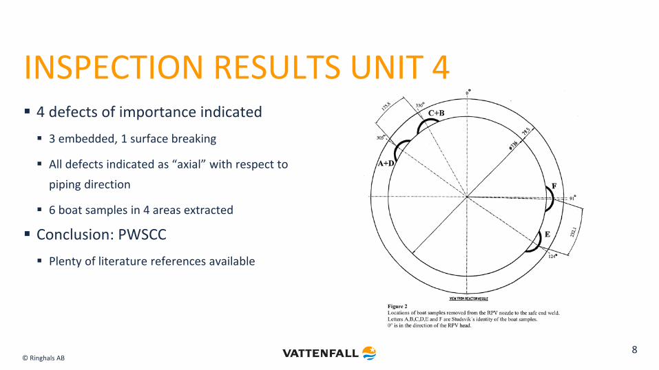
INSPECTION RESULTS UNIT 4 4 defects of importance indicated 3 embedded, 1 surface breaking
All defects indicated as “axial” with respect to piping direction
6 boat samples in 4 areas extracted
Conclusion: PWSCC Plenty of literature references available
8
© Ringhals AB
In fact: All where surface breaking The qualified inspection system failed to interpret all of the results as defects,
i.e. a discrimination error Possibly due to limitation of fixed reporting level of signal Inability to understand actual appearance of defect Big discrepancy of sizing above 10 mm and below approximately 5 mm! Have seen this previously at other similar locations! Results have been implemented in subsequent qualifications to allow for better and
more through inspection!
Defects tighter at surface breaking side than previously expected! Resulted in a large cooperative development program with participants from the
Swedish Utilities and the Qualification center SQC in the beginning of 2000s 9

© Ringhals AB
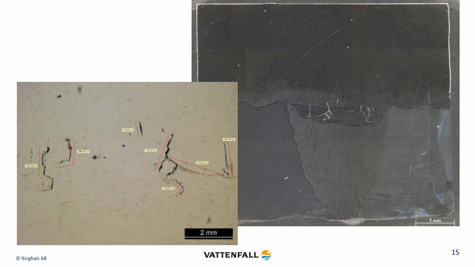
Carried out to determine damage mechanism but also to verify ISI-results Propagation by SCC
Branching - winding structure
Un-cracked ligaments
Indications of Hot-cracking (high Si-levels)
METALLOGRAPHY ANALYSIS
10

© Ringhals AB
No growth of defect in either of SS och CS! Have been noted previously in
other failure cases as well as the VC Summers case and Tsuruga case!
No circumferential defects larger than 2 mm in depth
11

© Ringhals AB
REMEDIES TO ISSUE: Stress improvement MSIP introduces compressive stresses in the inner layer exposed to the corrosive media
Laser/Shot peening gives a thinner layer but is in reality the equivalence
Inlay/Onlay welding Replacement of media touched material from the susceptible Alloy 600 weld metals, to the less susceptible
Alloy 690 weld metals
Thick layer replacement/Thin layer replacement
Weld Over Lay Optimized WOL
Full structural WOL
12

© Ringhals AB
WOL Qualification process differs
between US and EU ASME vs EN Main differences: EN has
”hard requirement” on hardness in base material and micro-fissures in weld metal.
13

© Ringhals AB
WOL Metallography: More or less all of the samples contained micro
fissures to a certain extent! Most in the appr. size of 100-200μm, some
extending several mm! Possible issue: what if future inspection
systems pick up defects in the fusion zone!
14
© Ringhals AB 15
© Ringhals AB
SAFE END REPAIR PROGRAM Welding of a less susceptible top layer preferable to complete exchange Divots ground and filled with Alloy 82
Belt line machined and filled with Alloy 52M
10 WPSs - Including temper bead welding at LAS-Nozzle!
Small gap where Alloy 52 can be welded successfully at old materials!
Excellent final result but: 10 days outage elongation
Repairs in the media touched surface
The repair program demonstrated the need for an extensive qualification of procedures
16
© Ringhals AB 17
© Ringhals AB
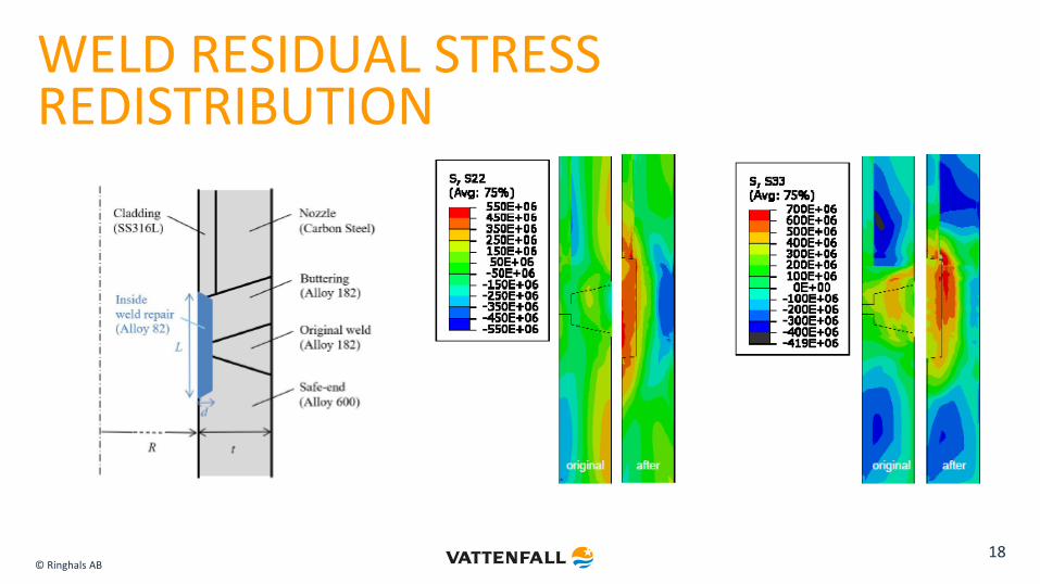
WELD RESIDUAL STRESS REDISTRIBUTION
18

© Ringhals AB
THIN WALLED TUBING
19

© Ringhals AB
THICK WALLED TUBING
20
© Ringhals AB
CONCLUSIONS In the Ringhals case, in-lay welding was considered as the best option! Assessment of the different alternatives important on beforehand! In the case of in-lay welding, make sure that a) the replacement material is
sufficiently resistant to previous degradation mechanisms and b) the thickness of the layer takes in to account both consequent ISI and stress redistribution!
Make sure that the ageing management guidelines are adapted to include any such repairs! Need to contain a full strategy on inspection, maintenance, repair and replacement, all given the overall estimated expected life time, as a guiding light! Use this tool to assess the possible options!
21