mk6 mm/ega technical manual - autoflame
TRANSCRIPT

M.M./E.G.A. Technical Manual
ISSUE: 1.11.2005 Autoflame Technical Manual Section
M.M./E.G.A. Technical Manual
This manual and all the information contained herein is copyright of Autoflame Engineering Limited.It may not be copied in the whole or part without the consent of the Managing Director.
Autoflame Engineering's policy is one of continuous improvement in both design and manufacture.We therefore reserve the right to amend specifications and/or data without prior notice. All detailscontained in this manual are correct at the time of going to press.
Registered Holder:
Company:
Department:
®
0
Issued by:
AUTOFLAME ENGINEERING LIMITEDUnit 19, Bellingham Trading Estate
Franthorne Way, BellinghamLondon SE6 3BX
Tel. +44 (0)20 8695 2000Fax. +44 (0)20 8695 2010Email: [email protected]
Website: http://www.autoflame.com/
Mk6EvolutionMM60001/E
Mini Mk6
MMM60016
Mini Mk5EvolutionMMM5002/E

M.M./E.G.A. Technical Manual
ISSUE: 1.11.2005 Autoflame Technical Manual Section
123456789012345678901234567890121234567890123456789012345678901212123456789012345678901234567890121234567890123456789012345678901212123456789012345678901234567890121234567890123456789012345678901212123456789012345678901234567890121234567890123456789012345678901212123456789012345678901234567890121234567890123456789012345678901212123456789012345678901234567890121234567890123456789012345678901212123456789012345678901234567890121234567890123456789012345678901212123456789012345678901234567890121234567890123456789012345678901212123456789012345678901234567890121234567890123456789012345678901212123456789012345678901234567890121234567890123456789012345678901212123456789012345678901234567890121234567890123456789012345678901212123456789012345678901234567890121234567890123456789012345678901212123456789012345678901234567890121234567890123456789012345678901212123456789012345678901234567890121234567890123456789012345678901212123456789012345678901234567890121234567890123456789012345678901212123456789012345678901234567890121234567890123456789012345678901212123456789012345678901234567890121234567890123456789012345678901212123456789012345678901234567890121234567890123456789012345678901212123456789012345678901234567890121234567890123456789012345678901212123456789012345678901234567890121234567890123456789012345678901212123456789012345678901234567890121234567890123456789012345678901212123456789012345678901234567890121234567890123456789012345678901212123456789012345678901234567890121234567890123456789012345678901212123456789012345678901234567890121234567890123456789012345678901212123456789012345678901234567890121234567890123456789012345678901212123456789012345678901234567890121234567890123456789012345678901212123456789012345678901234567890121234567890123456789012345678901212123456789012345678901234567890121234567890123456789012345678901212123456789012345678901234567890121234567890123456789012345678901212123456789012345678901234567890121234567890123456789012345678901212123456789012345678901234567890121234567890123456789012345678901212123456789012345678901234567890121234567890123456789012345678901212123456789012345678901234567890121234567890123456789012345678901212123456789012345678901234567890121234567890123456789012345678901212123456789012345678901234567890121234567890123456789012345678901212
1234567890123456789012345678901212345678901234567890123456789012123456789012345678901234567890121234567890123456789012345678901212345678901234567890112345678901234567890123456789012123456789012345678901234567890121234567890123456789012345678901212345678901234567890123456789012123456789012345678901123456789012345678901234567890121234567890123456789012345678901212345678901234567890123456789012123456789012345678901234567890121234567890123456789011234567890123456789012345678901212345678901234567890123456789012123456789012345678901234567890121234567890123456789012345678901212345678901234567890112345678901234567890123456789012123456789012345678901234567890121234567890123456789012345678901212345678901234567890123456789012123456789012345678901123456789012345678901234567890121234567890123456789012345678901212345678901234567890123456789012123456789012345678901234567890121234567890123456789011234567890123456789012345678901212345678901234567890123456789012123456789012345678901234567890121234567890123456789012345678901212345678901234567890112345678901234567890123456789012123456789012345678901234567890121234567890123456789012345678901212345678901234567890123456789012123456789012345678901123456789012345678901234567890121234567890123456789012345678901212345678901234567890123456789012123456789012345678901234567890121234567890123456789011234567890123456789012345678901212345678901234567890123456789012123456789012345678901234567890121234567890123456789012345678901212345678901234567890112345678901234567890123456789012123456789012345678901234567890121234567890123456789012345678901212345678901234567890123456789012123456789012345678901123456789012345678901234567890121234567890123456789012345678901212345678901234567890123456789012123456789012345678901234567890121234567890123456789011234567890123456789012345678901212345678901234567890123456789012123456789012345678901234567890121234567890123456789012345678901212345678901234567890112345678901234567890123456789012123456789012345678901234567890121234567890123456789012345678901212345678901234567890123456789012123456789012345678901123456789012345678901234567890121234567890123456789012345678901212345678901234567890123456789012123456789012345678901234567890121234567890123456789011234567890123456789012345678901212345678901234567890123456789012123456789012345678901234567890121234567890123456789012345678901212345678901234567890112345678901234567890123456789012123456789012345678901234567890121234567890123456789012345678901212345678901234567890123456789012123456789012345678901123456789012345678901234567890121234567890123456789012345678901212345678901234567890123456789012123456789012345678901234567890121234567890123456789011234567890123456789012345678901212345678901234567890123456789012123456789012345678901234567890121234567890123456789012345678901212345678901234567890112345678901234567890123456789012123456789012345678901234567890121234567890123456789012345678901212345678901234567890123456789012123456789012345678901123456789012345678901234567890121234567890123456789012345678901212345678901234567890123456789012123456789012345678901234567890121234567890123456789011234567890123456789012345678901212345678901234567890123456789012123456789012345678901234567890121234567890123456789012345678901212345678901234567890112345678901234567890123456789012123456789012345678901234567890121234567890123456789012345678901212345678901234567890123456789012123456789012345678901123456789012345678901234567890121234567890123456789012345678901212345678901234567890123456789012123456789012345678901234567890121234567890123456789011234567890123456789012345678901212345678901234567890123456789012123456789012345678901234567890121234567890123456789012345678901212345678901234567890112345678901234567890123456789012123456789012345678901234567890121234567890123456789012345678901212345678901234567890123456789012123456789012345678901123456789012345678901234567890121234567890123456789012345678901212345678901234567890123456789012123456789012345678901234567890121234567890123456789011234567890123456789012345678901212345678901234567890123456789012123456789012345678901234567890121234567890123456789012345678901212345678901234567890112345678901234567890123456789012123456789012345678901234567890121234567890123456789012345678901212345678901234567890123456789012123456789012345678901123456789012345678901234567890121234567890123456789012345678901212345678901234567890123456789012123456789012345678901234567890121234567890123456789011234567890123456789012345678901212345678901234567890123456789012123456789012345678901234567890121234567890123456789012345678901212345678901234567890112345678901234567890123456789012123456789012345678901234567890121234567890123456789012345678901212345678901234567890123456789012123456789012345678901123456789012345678901234567890121234567890123456789012345678901212345678901234567890123456789012123456789012345678901234567890121234567890123456789011234567890123456789012345678901212345678901234567890123456789012123456789012345678901234567890121234567890123456789012345678901212345678901234567890112345678901234567890123456789012123456789012345678901234567890121234567890123456789012345678901212345678901234567890123456789012123456789012345678901

M.M./E.G.A. Technical Manual
ISSUE: 1.11.2005 Autoflame Technical Manual Section
10
9
8
7
6
5
4
3
1
01
2E.G.A.
M.M.
I.B.S.
W.L.
D.T.I.
INDEX
Overview and Introduction to the Features and Benefits of the
Micro Modulation Fuel Air Ratio Control, ControlBox Functions & P.I.D. Load Controller.
Exhaust Gas Analysis Trim System CO2 + CO + O2+ Flue Temp. + Eff. Monitoring NO & SO2.
Intelligent Boiler SequencingLead Lag Selection.
Water Level Control, First Out Annunciation,Bottom Blowdown and TDS Management
Data Transfer Interface Remote Control, Monitoringand Data Acquisition from Total System.
Application Possibilities for the M.M. E.G.A. System.
Ancillary & Peripheral Equipment for the M.M. E.G.A. System,Oil & Gas Valves, Positioning Motors, Load Detectors.
Miscellaneous Component Information: Parts List.
Appendix: Approvals, Compatibility, Warranty,Terms and Conditions etc.
M.M./E.G.A. System.
2

M.M./E.G.A. Technical Manual
ISSUE: 1.11.2005 Autoflame Technical Manual Section 02
Important Notes
A knowledge of combustion related procedures and commissioning is essential before embarking workon any of the M.M./E.G.A. systems. This is for safety reasons and effective use of the M.M./ E.G.A.system. Hands on training is required. For details on schedules and fees relating to group trainingcourses and individual instruction, please contact the Autoflame Engineering Ltd. offices at the addresslisted on the front.
Introduction
Short Form - General Terms and Conditions
A full statement of our business terms and conditions are printed on the reverse of all invoices. A copyof these can be issued upon application, if requested in writing.
The System equipment and control concepts referred to in this Manual MUST be installed, commis-sioned and applied by personnel skilled in the various technical disciplines that are inherent to theAutoflame product range, i.e. combustion, electrical and control.
The sale of Autoflame’s systems and equipment referred to in this Manual assume that the dealer,purchaser and installer has the necessary skills at his disposal. i.e. A high degree of combustionengineering experience, and a thorough understanding of the local electrical codes of practiceconcerning boilers, burners and their ancillary systems and equipment.
Autoflame’s warranty from point of sale is two years on all electronic systems and components.One year on all mechanical systems, components and sensors.
The warranty assumes that all equipment supplied will be used for the purpose that it was intended andin strict compliance with our technical recommendations. Autoflame’s warranty and guarantee islimited strictly to product build quality, and design. Excluded absolutely are any claims arising frommisapplication, incorrect installation and/or incorrect commissioning.
If in doubt regarding any technical aspect of the system contact your authorised dealer or the AutoflameTechnical Sales Department. Either of the above will be pleased to give advice and TechnicalInformation.

M.M./E.G.A. Technical Manual
ISSUE: 1.11.2005 Autoflame Technical Manual Section
Section 1: Overview and Introduction of M.M. E.G.A. System
1.1 Schematic of M.M./E.G.A. System Capabilities and Inter-Relationship of Software Modules
1.2 Schematic Illustrating Burner Combination Possibilities
1.3 Schematic Illustrating Typical System Application
1.4 Burner Management Systems Comparison
1.5 Overview of Micro Modulation System
1.6 Overview of Exhaust Gas Analysis
1.7 Overview of Intelligent Boiler Sequencing
1.8 Overview of the Data Transfer Interface
1.9 Overview of the Additional Modules
1.10 Overview of P.C. Compatibility
1.11 Overview of the Analogue Output Unit
1: Index

M.M./E.G.A. Technical Manual
ISSUE: 1.11.2005 Autoflame Technical Manual Section
DDDD D.T
.I..T
.I..T
.I..T
.I..T
.I.
DA
TA TR
AN
SFER
INTE
RFA
CE
REM
OTE
MO
NIT
ORI
NG
&C
ON
TRO
L V
IA D
.T.I.
ALT
ER S
ETPO
INTS
, TU
RNBU
RNER
S O
N O
R O
FF.
VIE
W &
HA
RD C
OPY
OF
ALL
SYS
TEM
DA
TA.
E.C
.E.C
.E.C
.E.C
.E.C
.ER
RO
R C
HEC
KIN
GD
IAG
NO
STIC
SO
FTW
ARE
TO IN
TEN
SIV
ELY
INTE
RRO
GA
TETO
TAL S
YSTE
M.
SHO
WS
ERRO
R C
OD
E FO
RC
OM
PON
ENT O
R D
ATA
STO
RAG
E FA
ILU
RE.
TIM
E/D
ATE
/STA
TUS.
I.I.
S.
I.I.
S.
I.I.
S.
I.I.
S.
I.I.
S.
SPLI
TTER
MO
DU
LEFO
R EX
ISTI
NG
O2
TRIM
P.C
.C.
DO
WN
LOA
D A
LLC
OM
MIS
SIO
NIN
G D
ATA
FRO
M M
.M. M
OD
ULE
.SE
T U
P A
ND
CA
LIBR
ATE
E.G
.A.
VIA
RS2
32 S
ERIA
L PO
RT.
LOG
RU
NN
ING
TELE
CO
MN
ETW
ORK
PC
W
ITH
MO
NIT
ORI
NG
SOFT
WA
RE
CLI
ENT'
SB.
M.S
.
MO
DEM
I.B
.S.
I.B
.S.
I.B
.S.
I.B
.S.
I.B
.S.
INTE
LLIG
ENT
BO
ILER
SEQ
UEN
CIN
G
Lea
d/L
ag
HO
T W
ATE
R-ST
EAM
LEA
D/L
AG
LO
AD
DIS
TRIB
UTI
ON
F.F.
M.
F.F.
M.
F.F.
M.
F.F.
M.
F.F.
M.
FUEL
FLO
WM
EASU
REM
ENT
IN
STA
NTA
NEO
US
&TO
TALI
ZED
VA
LUES
M.M
.M
.M.
M.M
.M
.M.
M.M
.M
icro
Mo
dul
atio
n
FU
EL A
IR R
ATI
O C
ON
TRO
LP.
I.D.
LOA
D C
ON
TRO
LC
ON
TRO
LS 3
/4 P
OSI
TIO
NIN
G M
OTO
RSSO
FTW
ARE
FO
R TE
MPE
RATU
RE O
R PR
ESSU
REIN
TERN
AL
FLA
ME
SAFE
GU
ARD
TWIN
BU
RNER
CA
PABI
LITY
AS
STA
ND
ARD
VA
RIO
US
LOA
D D
ETEC
TORS
AV
AIL
ABL
ED
ISPL
AYS
CH
AN
NEL
PO
SITI
ON
SRE
QU
IRED
SET
POIN
T &
AC
TUA
L
LIM
ITS
CO
, CO
², O
²,N
O &
EX
H T
EM
PU
SER
SELE
CTA
BLE
UPP
ER &
LO
WER
LIM
ITS
O2,
CO
2, C
OA
BSO
LUTE
LIM
ITS
ALA
RM O
NLY
/BU
RNER
SH
UTD
OW
N
E.G
.A.
E.G
.A.
E.G
.A.
E.G
.A.
E.G
.A.
EXH
AU
ST G
AS
AN
ALY
SER
3 P
ARA
MET
ER TR
IM C
O, C
O² &
O²
EFFI
CIE
NC
Y &
EXH
AU
ST TE
MPE
RATU
RE
OPT
ION
AN
ALY
SIS
FOR
NO
& S
O²
DIS
PLA
YS A
LL O
F ABO
VE
"CO
MM
ISSI
ON
ED"&
"ON
-LIN
E" V
ALU
ES.
6 O
PTIO
NA
L OU
TPU
TSI
GN
ALS
4-2
0mA
.
An
alo
gA
na
log
An
alo
gA
na
log
An
alo
gI.
O.
I.O
.I.
O.
I.O
.I.
O.
MO
DU
LE
MO
DU
LE
MO
DU
LE
MO
DU
LE
MO
DU
LE
Inpu
t/O
utpu
t M
odul
e6
in/6
out
x 4
-20m
A.
Dig
ita
lD
igit
al
Dig
ita
lD
igit
al
Dig
ita
lI.
O.
I.O
.I.
O.
I.O
.I.
O.
MO
DU
LE
MO
DU
LE
MO
DU
LE
MO
DU
LE
MO
DU
LE
Inpu
t/O
utpu
t M
odul
e8
x V
olt
Free
Con
tact
s16
x L
ine
Inpu
ts
SCHEMATIC OF M.M. E.G.A. SYSTEM CAPABILITIES &INTER RELATIONSHIP OF SOFTWARE MODULES.
1.1.1
W.L
.W
.L.
W.L
.W
.L.
W.L
.
WA
TER
LEV
EL C
ON
TRO
L
MO
DU
LATI
NG
FEE
DW
ATE
R V
ALV
EPU
MP
ON
/OFF
STEA
M F
LOW
MET
ERIN
GFI
RST
OU
T A
NN
UN
CIA
TIO
NSU
RFA
CE
BLO
WD
OW
N/T
.D.S
.BO
TTO
M B
LOW
DO
WN

M.M./E.G.A. Technical Manual
ISSUE: 1.11.2005 Autoflame Technical Manual Section
Overview - Features and Benefits of the Autoflame MicroModulation and Exhaust Gas Analysis Trim Systems
M.M. Micro Modulation/Flame Safeguard
* Fuel/air ratio control
* Control up to 4 positioning motors and 2 variable speed drives (VSD/VFD)- 6 channels
* 4 independent fuel programs
* Fully adjustable P.I.D. load control for temperature and pressure
* External voltage/current load control and setpoint adjustment
* Various boiler load detectors available
* Twin burner capability
* Fully compatible with control frequency drives
* Fuel flow metering software
* Internal flame safeguard- full flame supervision with UV self check
* Gas valve train leak supervision and gas pressure monitoring
* Air windbox pressure proving and monitoring
E.G.A. Exhaust Gas Analysis
* 3 parameter Trim of O², CO² and CO
* Displays O², CO², CO Efficiency, Delta T and exhaust gas temperature
* NO, SO² (or NO²) monitoring
* Local display for re-calibration, changing cells, user configuration andstand-alone operation
* Upper/lower/absolute limits for O², CO², CO, NO and exhausttemperature
* Six 4-20mA output signals to interface with other controls/chart recorders
1.1.2

M.M./E.G.A. Technical Manual
ISSUE: 1.11.2005 Autoflame Technical Manual Section
I.B.S. Intelligent Boiler Sequencing (Lead/Lag control)
* System will Sequence hot water boilers and steam boilers via lead/lagload distribution
* Fully adjustable via user option with the system to enable the control tobe tailored to the application
* System control for isolation of valves or pumps
* Phantom setpoint and standby warming for lag boilers via a timingsequence and pressure offset or aquastat
D.T.I. Data Transfer Interface
* System will collect operational data for up to 10 M.M. modules on onesite, transmit via RS232 data link to a local PC running winPCDTI orBuilding Management System (B.M.S.)
* Modem compatibility software to give information and control of boilerhouse operation remotely
* MODBUS and Johnson's Metasys compatible
I.I.F. O² Interface Module, Splitter Module
* Interface with existing on-line O² analysers via 4-20mA
* Split one E.G.A. signal for two M.M.s for use on common or twin furnaceboilers
P.C.C. Personal Computer Compatible
* Down load all commissioning data from M.M. module
* Set up and calibrate E.G.A. via RS232 serial port
I/O Digital & Analogue Input/Output Units
* These units can be configured to give inputs and outputs for the DTIsystem
* Analog modules have six 4-20mA inputs and outputs
* Digital modules have 16 line voltage inputs and 8 volt free contacts
* All inputs/outputs can be labelled for the specific application and setfor alarm or monitor only status
1.1.3

M.M./E.G.A. Technical Manual
ISSUE: 1.11.2005 Autoflame Technical Manual Section 1.2.1
LIVE SUPPLY
winPCDTI
USER INTERFACES
GUN TYPE BURNERDUAL FUEL
GUN TYPE BURNERDUAL FUEL
ROTARY INDUSTRIALBURNER DUAL FUEL
LEAD BOILERSELECT SWITCH
1 AMP
MODBUS/Metasys compatible
Modem

M.M./E.G.A. Technical Manual
ISSUE: 1.11.2005 Autoflame Technical Manual Section 1.3.1

M.M./E.G.A. Technical Manual
ISSUE: 1.11.2005 Autoflame Technical Manual Section
Burner Management Systems Comparison
1.4.1
Mini Mk5 EVO MMMini Mk6 MMMk6 MM
Mk6 Mini Mk6 Mini Mk5 EVOMicro Modulation Fuel/Air Ratio ControlServo channels 4 3 or 4 3VSD channels 2 0 or 1 0Fuel profiles 4 4 2Selectable trim channel (Damper or VSD)
Error diagnostics displayed
Single point change
User defined optimum ignition
FGR management
Exhaust Gas Analyser (requires EGA)CO2, O2, CO trim
CO2, O2, CO, NO, SO2 displayed
Exhaust temperature and combustion efficiency displayed
User definable limits to CO2, O2, CO
Burner ControlUser configurable timings
Internal flame safeguard controller for UV
Gas valve proving system -Air wind-box pressure proving -Gas pressure supervision -Air pressure supervision -Oil pressure supervision -Lockout history
Setpoint ControlInternal 3 term PID load control to required setpoint
Software adjustable thermostat/pressure-stat
Second setpoint selectable
Outside temperature compensation - -Night setback facility - -Further FeaturesIBS hot water
IBS steam
IBS low pressure steam -Fuel flow metering - instantaneous
Fuel flow metering - totalised
Hand/Auto/Low flame hold
Input for external load control 4-20mA/0-10V 4-20mA/0-10V 0-10VOutput of firing rate 4-20mA/0-10V - -Twin burner capability -User FeaturesPassword protected configurable options and parameters
Infrared communications port
Systems data export via DTI
Internal calendar clock display and logging -Proximity sensor screen saver - -LCD Display 1/4 VGA 20x4 line 20x4 line

M.M./E.G.A. Technical Manual
ISSUE: 1.11.2005 Autoflame Technical Manual Section
Overview: M.M.
1.5.1
MICRO MODULATION (M M)
Overview of System Operation: Features and Benefits
To ensure maximum efficiency in the operation of any boiler, two requirements are of paramountimportance, the first being that the air to fuel ratio is kept to the minimum to ensure completecombustion within the limitations of the combustion head design and that these settings once arrivedat are infinately repeatable to an incredibly high degree of accuracy. The second requirement shouldbe that the target temperature or pressure of the boiler is monitored by the combustion system andthat at all times exactly the right amount of fuel and air is fire to achieve the target value and thatat no time irrespective of load change is this target exceeded or fallen short of.
The inherent hysterisis of all mechanical systems that have traditionally involved cams and linkagesto characterise the fuel air ratio have made this sort of accuracy impossible. The accuracy of responseof fuel input to the monitored target temperature/pressure of the boiler has meant that the targetvalue set by the operator has at most times been exceeded or fallen short of.
The Micro Modulation system provides an easily programmable and flexible means of optimisingcombustion quality throughout the load requirement range of the boiler/burner unit whilst ensuringthe temperature is accurate to within 1 deg C (2 deg. F.) and pressure to within 1.5 p.s.i. The maximumerror in degrees angular rotation between the two servo motors at any position in the load range is 0.1degrees.
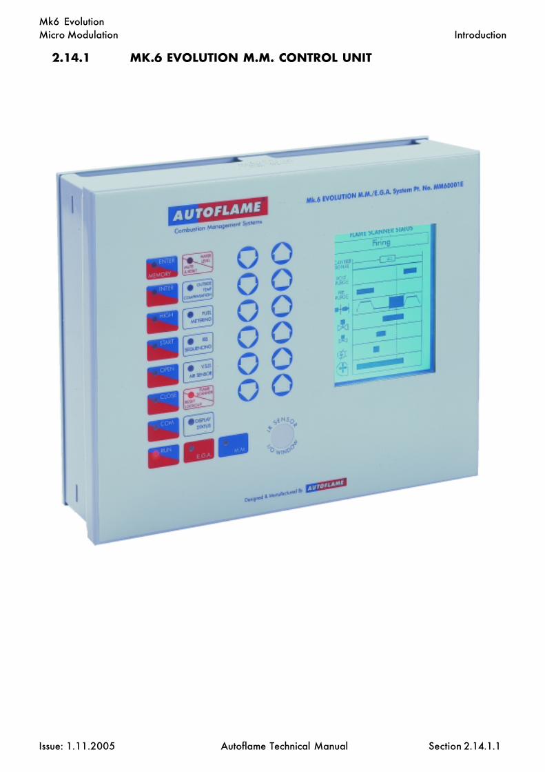
At the heart of the system is the control module which contains the micro computer and power supply.The display panel features touch sensitive key pad entry data, readouts and status indicators, allprotected beneath a tamper-proof transparent plastic cover. The M.M. system shows angular positionof air damper motor and fuel valve. “Required” and “Actual” temperatures are displayed.
Interfaced with the control module by means of high speed solid state switching are up to three dualwound servo motors. One motor is responsible for positioning the air damper and the other operatesa fuel valve by which it is possible to meter the input of gas, oil, or dual fuel.
The position of each servo motor is monitored by a voltage dividing system enabling digitalisedposition information to be encoded into the control modules memory. The relative positions of theair and fuel motors are constantly checked by the system at the rate of 50 times per second.
This new system of burner control achieves ‘Locked On’ near stoichiometric air fuel mixing throughoutthe fuel input range of the boiler while maintaining exact temperature or pressure target values.The load control incorporates user variable P.I.D. values.
Operating in conjunction with the above control specification is a full three term infinitely adjustableP.I.D. load control package. This ensures that the control of set point temperature is accurate to within1 deg C (2 deg F.) and pressure to within 0.1 bar (1.5 P.S.I.) Software for temperature or pressure is auser variable option, also various ranges of temperature and pressure are selectable by the user.

M.M./E.G.A. Technical Manual
ISSUE: 1.11.2005 Autoflame Technical Manual Section
Overview: M.M.
1.5.2
The Micro Modulation (M.M.) module is the basic building block of the M.M./E.G.A. system. Acomplete system based on the Mk6 MM incorporates all of the following control facilities and features:
· 6 channel: 4 positioning motors and 2 Variable Speed Drive interfaces.· 4 separate fuel profiles· Full flame supervision control with UV self check- system meets self check criteria on all outputs· A lockout history of the last 16 incidents held in memory. Time, date, function, re-set· Single point change capability· IBS steam sequencing with lead/lag· IBS heating boiler sequencing- lead/lag- control of return line 2 port valve· Gas valve train leak proving system· Gas pressure monitoring and display· High and Low gas pressure supervision· Oil pressure high/low limits· Oil pressure monitoring & display· User definable optimum ignition position selection- golden start- User definable flue gas recirculation ignition position selection· Variable modulation speed (motor travel time user variable)· Selectable trim channel· Burner control selectable operation- first/second safety times· Air wind box pressure proving- display & supervision· Internal PID 3 term load control- temperature & pressure· Outside temperature compensation of boiler set point, user adjustable with night seback facility· Fuel flow metering- instantaneous and totalised readings- user defined units of measurement· Exhaust temperature and ambient temperature net and absolute readings displayed· 3 parameter trim- CO2, O2 & CO· Combustion efficiency calculation- net or gross displayed· NO and SO2 monitoring & display· User definable combustion limits on all CO2, O2 & CO values· Second set point user selectable· Internal calendar clock display and logging functions· Software adjustable thermostat/pressure stat. facility· Hand/Auto/Low flame hold facilities· Password protection of all safety related options and parameters· Infrared Coms port for upload and download of commissioned data and lockout history· Twin burner control capability· 4-20mA/0-10V input for external load control of firing rate· 4-20mA/0-10V output confirming firing rate position· Changeover of fuels without shutdown (Special PROM)· Quarter VGA screen with dynamic display capabilities and IR proximity screen saver· 110 or 230 volt standard operation· Panel facing mounting

M.M./E.G.A. Technical Manual
ISSUE: 1.11.2005 Autoflame Technical Manual Section 1.5.3
SENSOR SERVO
SWITCH
EXTERNA
DRIVECH.5SPEEDVARIABLE FLAMEOR
DRAFTFORCED AUX.
SERVO
CH.4AIR AUX.
SERVOSERVO
CH.3CH.2U.V
LOAD OR
OIL
AIRPRESSURE
PRESSURESENSOR
OIL
CH.1
FUEL
PRESSURESENSOR
GAS
GAS
HIGH/LOW GASPRESSURE PROVING
VALVE PROVING
SENSOR
EXTERNAL
STEAMSENSORM
K6
EVO
LUTI
ON
BU
RNER
MA
NA
GEM
ENT
SYST
EM

M.M./E.G.A. Technical Manual
ISSUE: 1.11.2005 Autoflame Technical Manual Section
EXHAUST GAS ANALYSIS (E.G.A.) TRIM SYSTEM
Overview of E.G.A. System Operation
With the E.G.A. trim system it is possible to expand the M.M. so that it will measure and display O2, CO2,CO and exhaust temperature, together with boiler efficiency: At the same time inflicting minutecorrections on the air damper position to ensure that the originally entered commissioning data isadhered to, irrespective of variations in stack pressure or barometric conditions. As standard, outputsare available which can be connected with appropriate interfacing to an energy management computerto track and record the information that is generated by the E.G.A. system. To expand the M.M. systemto the above E.G.A. specification the additional sampling unit and exhaust gas sampling probe must bepurchased. The M.M./E.G.A. control form is P + I + D feed forward, and interpolates between all entereddata, it also carries error checking self diagnostic software for self identification of system componentor data handling failure.
The system trim function is achieved by every paired value for air and fuel having stored values for O2,CO2 and CO at the commissioned value. Deviations from these ideal values are held, this data isintegrated and expressed as a degree angular value, so that an exact amount of air damper trim maybe inflicted at any time to return the system to it’s commissioned value at any load condition.
The E.G.A. can also be fitted with NO and SO2 sensors for monitoring.
All the information available on the E.G.A. can be accessed by one or all three of the following methods:
1. Displayed on the E.G.A. local display.2. Displayed on the M.M. facia.3. 6 channel 4-20mA output facility for the above values.
Options #1 and #3 enable the E.G.A. to be used as a Stand Alone on-line continuous monitoring system.
E.G.A. setup and calibration is carried out via the local display or by a PC using an RS232 serial port.
Overview: E.G.A.
1.6.1

M.M./E.G.A. Technical Manual
ISSUE: 1.11.2005 Autoflame Technical Manual Section
Overview: I.B.S.
1.7.1
INTELLIGENT BOILER SEQUENCING (I.B.S)
Overview of I.B.S. System Operation
The Intelligent Boiler Sequencing software, which is included in every M.M./E.G.A. module, furtherextends the application possibilities of the system. The objective of this control form is to ensure thatthe minimum number of boiler/burner units are in operation at any one time to satisfy the heatrequirement imposed upon the boiler plant, particularly in the case of multi boiler installations.
There are two variations of I.B.S. software that can be selected by the user via the Options procedure.The first variation relates to heating boilers and the second variation to steam boilers.
Heating Boilers Sequential Control:
A maximum of ten M.M./E.G.A. modules may be interconnected by a two wire screened data cable:(See interconnection drawing). Any string of modules interconnected as detailed can have one of it’snumber designated No. 1 or lead boiler. This identifying of “lead” boiler is achieved by either of thefollowing methods:
a) Connecting a mains voltage onto terminal No. 41.b) Instructing the modules via the D.T.I. module (Data Transfer Interface) by software.
Once a “lead” boiler has been selected the system works in the following way:
Typically every five minutes the sequencing software in the lead boiler identifies it’s own firing rate bylooking at the position of the fuel valve in the load index and also the maximum heating capacity of theNo 1. “lead” boiler. This information would normally be entered when this boiler/burner unit iscommissioned. Having established percentage firing rate, and maximum heating capacity, the I.B.S.software calculates the amount of heat being contributed to the system by this boiler. The I.B.S. softwarein the “lead” M.M./E.G.A. module then contacts in turn each of the modules connected to this loopand gathers similar information from each. The “lead” module’s I.B.S. software then calculates theminimum number of boiler/burner units that need to be operational to satisfy the building load, imposedupon the plant at that time, and switches the remainder off.
There is a terminal connection on the M.M./E.G.A. module for controlling a two port valve that wouldnormally be installed in the boiler’s return pipe connection to the common return header. This facilityensures that boilers that are switched “off line” do not contribute return temperature water to the flowheader thereby diluting the flow temperature to the building: (See relevant data sheets and drawingsshowing the control sequence detailed above).
Example:There are four boilers interconnected as above, each with a heating capacity of 586kW(2MBtu.) In theevent of each boiler firing 440 kW (1.5MBtu) (3/4 of it’s maximum rate), the No. 1 lead boiler wouldinstruct the No. 4 boiler to shut down and boilers No.s 1, 2 and 3 would adjust their firing rate tomaximum.
In both cases the boilers are contributing 1758kW (6MBtu) to the system but, after intervention of theI.B.S. sequencing software, three boilers only are carrying the load which is a more fuel efficient methodof operation.

M.M./E.G.A. Technical Manual
ISSUE: 1.11.2005 Autoflame Technical Manual Section
Overview: I.B.S.
1.7.2
If the building load continued to decrease the three boilers would reach a point where they were eachfiring 381kW (1.3MBtu) each. At this point the I.B.S. software would switch off the No. 3 boiler as twoboilers would be capable of generating the 1172kW (4MBtu) required. When the load on the systemincreases, the reverse procedure applies, i.e. when, for example, two boilers are firing at near 100%load and the setpoint temperature on either of the modules is not being achieved, the I.B.S. softwarewould switch on a third boiler to assist with the generation of the heat requirement. Any boiler can benominated “lead” boiler by the connection of an input to the appropriate terminal or by a softwareinstruction via the D.T.I.
Steam Boiler Sequential Control:
When the I.B.S. software control package is applied to steam boilers, it’s operation is exactly the sameas above but with the additional features and enhancements as explained in the following.
In the case of heating boilers only two states in the control form exist, either on or off. When steam boilervariation of I.B.S. is optioned there are three states which are controlled sequentially. The first is “on-line”, this is when the boiler is operating purely under the control of the M.M./E.G.A. module's internalP.I.D. load controller.
The second state is “stand-by”: In this case the boiler is operated at a reduced pressure setpoint, e.g. ifthe on-line boiler or boilers are set at a setpoint of 7 bar (100 p.s.i.) the stand-by boiler controls at asetpoint of 5 bar (72 p.s.i.). In this way if the load increases the stand-by boiler can begin to contributesteam quickly. The reduced setpoint is a user variable option in the same way as the normal controlpressure setpoint.
The third state is “off-line”, this is with the burner shut down and the boiler is cold. If the load on the boilerhouse increases, this boiler would move into a “Stand By” condition.
Apart from the variations detailed above, the steam sequencing works in precisely the same way as theheating boiler sequencing: The sequencing software package ensures that at all times the minimumnumber of boilers are operational to satisfy the load imposed on the boiler house.

M.M./E.G.A. Technical Manual
ISSUE: 1.11.2005 Autoflame Technical Manual Section
REMOTE MONITORING AND CONTROL (D.T.I.)
Overview of Data Transfer Interface Operation
By means of our Data Transfer Interface (D.T.I.) module, all the operational data, stored within eachof up to ten M.M. modules, can be collected by the D.T.I. for transmission by direct RS232 data linkto a local terminal, screen and printer or Building Management System (B.M.S.). This facility can alsobe achieved remotely via modem/telecom link up. This cost effective system more than meets therequirements of today’s E.M.S. and B.M.S. systems in providing all the necessary operational and alarmstatus and control of boiler plant to achieve its maximum energy efficient operation.
Up to a maximum of ten M.M. modules (one per burner) can be connected to one D.T.I. module bymeans of a series RS485 data link. The information gathered by the D.T.I. from each M.M. module isthen available for transmission to the E.M.S. or B.M.S. via either an RS232 data link or modem/telecomdata link.
Remote on/off control of the burners can also be achieved as well as adjustment of the temperature orpressure setpoints and selection of sequence lead boiler. To accommodate the status information fromother plant related equipment, the D.T.I. can handle upto 160 direct mains voltage inputs, 80 volt freeoutputs, 60 4-20mA inputs and 60 4-20mA outputs. Typical remote E.M.S., B.M.S. information andoperational facilities that can be achieved are as follows, but are subject to the particular site andmanagement system requirements that are to be accommodated.
The capability exists within the standard D.T.I. software for the end user to label any mains voltage signalinput as an "Alarm" condition. When labelled as an "Alarm" condition the system can 'autodial' out ontothe general telephone network to a word pager and/or a remote office.
Possible Input/Output Values:
Values available from each MM :
Required boiler temperature (deg. C/F) or pressure (Bar/PSI).Actual boiler temperature (deg. C/F) or pressure (Bar/PSI).Burner on/off (internal stat on/off status).Burner maximum firing rate.Burner firing rate (%).M.M. identification number.Fuel selected.Boiler control detector type (temperature/pressure).Error conditions.Auto/Hand/Low flame hold operation.All MM channels (positioning motors and variable speed drives).Number of hours run/start-ups for each fuel.Instantaneous and totalised fuel flow metering.Lockout/error status.Online combustion air pressure.Online fuel sensor pressure.Data logging- online status, actual value, firing rate- stored in monthly accessible files.
Overview: D.T.I.
1.8.1

M.M./E.G.A. Technical Manual
ISSUE: 1.11.2005 Autoflame Technical Manual Section
Overview: D.T.I.
Values available from each MM : cont../...
Maximum set point accepted from DTI.Minimum set point accepted from DTI.Lead boiler status.Burner firing status (off, firing, purge, ignition, pilot proving, main flame proving).Sequencing optioned.Sequence status (on, stand-by, warming, off).Enabled/disabled status.
Additional information available if system has E.G.A.:
E.G.A. operation optioned.Flue gas oxygen present value.Flue gas carbon dioxide present value.Flue gas carbon monoxide (unburnt combustibles) present value.Flue gas nitrogen oxide present value.Flue gas sulphur dioxide present value.Flue gas exhaust temperature present value.Ambient temperature present value.Delta T present value (difference between exhaust temperature and ambient temperature).Combustion efficiency present value.Flue gas oxygen commission value.Flue gas carbon dioxide commission value.Flue gas carbon monoxide (unburnt combustibles) commission value.Flue gas nitrogen oxide commission value.Flue gas sulphur dioxide commission value.Flue gas exhaust temperature commission value.Ambient temperature commission value.Delta T commission value (difference between exhaust temperature and ambient temperature).Combustion efficiency commission value.E.G.A. error conditions.
DTI control input values:
Change required set point- global and individual.Select lead boiler.Shuffle sequencing- change lead/lag order.Boiler enable/disable.Change load index/firing rate- global and individual.
Additional information available if system has Water Level controls:
Water level status- control point, high water, 1st low water, 2nd low water, pre-alarms.Steam temperature, feedwater temperature, pump status and valve position.Instantaneous and totalised steam flow metering.Water level alarm status.15 First Out annunciation input status.T.D.S. (Total Dissolved Solids) target and measured values- surface blowdown.
1.8.2

M.M./E.G.A. Technical Manual
ISSUE: 1.11.2005 Autoflame Technical Manual Section
ADDITIONAL MODULES
1. O2 Interface.
Where an existing O2 measuring device is fitted the O2 interface module can receive a 4-20mA signalfrom the O2 probe and a 0-10V signal from the thermocouple mounted in the stack for use by the M.M.for one parameter O2 trim. Values for CO2, CO, Exhaust Gas Temperature and Efficiency will bedisplayed as 0.
2. EGA Splitter.
On water tube or common furnace boilers it is possible to use one E.G.A. unit to sample the commonflue gases and split the signal for use by two M.M. modules. Trim is inflicted on both burners based onthe common products of combustion and will therefore not optimise the combustion performance ofeach burner.
Overview: Additional Modules
1.9.1

M.M./E.G.A. Technical Manual
ISSUE: 1.11.2005 Autoflame Technical Manual Section
Overview: P.C.C.
1.10 P.C. COMPATIBILITY
M.M. Infrared Upload/Download
The Mk.6, mini Mk.6 and mini Mk.5 EVO M.M. units each contain an Infra Red Upload/Downloadport which enables all the commissioning data from a single unit to be downloaded onto a PC usingAutoflame IR lead and software. Data can be stored on disk. Stored backup data can be uploaded into the M.M.
Information includes:
1. Site name, Engineer, Boiler Type, Data, Software revisions, M.M. identification number.2. All channel positions entered during commissioning for each fuel.3. E.G.A. values O2%, CO2%, COppm, NOppm, SO2ppm, Ambient Temperature, Exhaust
temperature, Delta T, Efficiency % for commissioned, and also autotrim values of O2,CO2 and CO at each position.
4. All Option number setting, default- * indicates options changed.5. All Parameter numbers, setting, default- * indicates Parameters changed.6. Flow Metering - if entered.7. Lockout/error history (last 16 events).8. Water level commissioned data and set-up values.9. First Out annunciation labels.10. Bottom blowdown timings and surface blowdown settings.
which can then be used to generate a hard copy Commissioning Report and be stored on disk forfuture reference.
E.G.A.
The E.G.A. is fitted with a local display. All set-up, configuration and calibration tasks (calibrationcode and test gas calibration) can be carried out with the use of this display and facia buttons. Eachcell is provided with its own unique calibration number which alleviates the need for costly on sitecalibration with test gas etc. It is also possible to use the RS232 serial port on the E.G.A. for connectionto a P.C. to carry out the above procedures.
1.10.1

M.M./E.G.A. Technical Manual
ISSUE: 1.11.2005 Autoflame Technical Manual Section
1.11 ANALOGUE INPUT/OUTPUT UNIT
This unit has 6 individually programmable outputs and 6 individually programmable inputs providinga means of converting items of data within the M.M./E.G.A. system in 4-20mA signals.
The unit can be supplied with outputs readily configured or with the use of the DTI lead and WindowsTerminal mode software the outputs are user configurable.
The following functions are available for output data:-
Firing Rate - Percentage %Actual - Temperature/Pressure, °C/°F or bar/psi.Required - Temperature/Pressure, °C/°F or bar/psi.NO - p.p.m.CH1 - Angular Degrees of travel.CH2 - Angular Degrees of travel.CH3 - Angular Degrees of travel.CH4 - Angular Degrees of travel.% O2 Flue - Percentage %% CO2 Flue - Percentage %CO Flue - p.p.m.Exhaust Temp. - Degrees °CEfficiency - Percentage %Fuel Flow Rate - Units/Min.MM Error - 4mA no error, 20mA error.EGA Error - 4mA no error, 20mA error.
Additionally, the A I/O can be connected directly to a Mini Mk5. In this case, the A I/O uses terminals48 and 49 of the M.M. therefore neither Sequencing nor the D.T.I. may be used with the A I/O.Channel 1 input can be used as the Remote setpoint change.
Overview: A.O.U.
1.11.1

Micro Modulation
Issue: 1.11.2005 Autoflame Technical Manual Section
Mk6 Evolution
2.14.1 Mk.6 M.M. Control Unit
2.14.2 Commissioning and Setting Up Procedure2.14.2.1 Introduction2.14.2.2 Programming Fuel/Air Positions2.14.2.3 Setting Positioning Motors2.14.2.4 Setting Options2.14.2.5 Setting Parameters2.14.2.6 Valve Proving
2.14.2.6.1 Explanation2.14.2.6.2 Gas Pressure Sensor2.14.2.6.2.1 Oil Pressure Sensor2.14.2.6.3 Commissioning Valve Proving
2.14.2.7 Air Pressure Proving2.14.2.7.1 Explanation2.14.2.7.2 Air Pressure Sensor2.14.2.7.3 Air Pressure Tapped Fitting
2.14.2.8 Outside Air Temperature Compensation2.14.2.8.1 Explanation2.14.2.8.2 Outside Air Sensor
2.14.2.9 Electrical Specifications2.14.2.9.1 Classifications2.14.2.9.2 Fuse Ratings2.14.2.9.3 Terminals Description2.14.2.9.4 Cables
2.14.2.10 Variable Speed Drives2.14.2.11 Installation Checks
2.14.3 Control Box Functions2.14.3.1 Burner Control Sequence Diagrams2.14.3.2 Self Check UV Scanner2.14.3.3 Standard European UV Scanner - Side viewing2.14.3.4 Standard North American UV Scanner - End viewing2.14.3.5 Selection of UV Scanner Types2.14.3.6 UV Self Adaptive Pulse Width Modulation
2.14.4 Error Checking, Self Diagnostic Fault Analysis, I.D. Codes2.14.4.1 Key to Errors2.14.4.2 Key to Lockouts2.14.4.3 Troubleshooting
2.14.5 End User Day to Day Operation2.14.5.1 Normal Run Operation2.14.5.2 Adjusting Clock Settings, Contrast and Actual Load Reading2.14.5.3 EPROM Version Numbers
2.14: Index
Section 2.14: Mk6 M.M. Micro Modulation

Micro Modulation
Issue: 1.11.2005 Autoflame Technical Manual Section
Mk6 Evolution
2.14.6 Electrical Schematics Showing all Terminal Interconnections2.14.6.1 Mk.6 Connection Diagram2.14.6.3 Boiler Steam Pressure Detector Connection Diagram2.14.6.6 E.G.A. Mk6 Interconnection Diagram2.14.6.10 Splitter Interface Interconnection Diagram2.14.6.11 O2 Interface Interconnection Diagram
2.14.7 Twin Burner Operation2.14.7.1 Operations/Guidelines2.14.7.3 Interconnecting Wiring
2.14.8 Hand/Auto and Low Flame Hold Facilities
2.14.9 Fault Finding
2.14.10 Other Information and Illustrations2.14.10.1 Mk.6 M.M. Front Facia Details2.14.10.2 Mk.6 M.M. Enclosure Dimensions2.14.10.3 IR Download Lead2.14.10.4 Maintenance and Servicing2.14.10.5 Installation Precautions
2.14.11 Fuel Flow Measurement and Metering operation
2.14.12 Golden Start choke operation
2.14.13 One Point Change Facility
2.14.14 Flue Gas Recirculation
2.14.15 Pause Facility
2.14.16 Time Clock Facility
2.14.18 Automatic Re-commission of air and gas sensors2.14.18.1 Air sensor re-commission2.14.18.2 Gas sensor re-commission
2.14.19 Flame Detection Using External Flame Switch
2.14.20 On-line Changes
2.14: Index
Section 2.14: Mk6 M.M. Micro Modulation
Micro Modulation
Issue: 1.11.2005 Autoflame Technical Manual Section
Mk6 EvolutionIntroduction
2.14.1 MK.6 EVOLUTION M.M. CONTROL UNIT
2.14.1.1
Micro Modulation
Issue: 1.11.2005 Autoflame Technical Manual Section
Mk6 Evolution
2.14.2 MK.6 COMMISSIONING AND SETTING UP PROCEDURES
2.14.2.1 Introduction
Important Note: Prior to commissioning, the fuel and air servomotors must be calibrated to ensurethat the position of the valves and dampers are corresponding to the potentiometer feed-back signal asdisplayed on the Mk6 screen/display, i.e. when the valve is fully closed, the Mk6 displays zero degrees.
The commissioning procedure as described must be strictly adhered to.Anybody commissioning a Micro Modulation system must have anadequate understanding of combustion plant. In the wrong handshazardous conditions could be made to exist. The Autoflame product mustonly be installed, set-up, commissioned and adjusted by an Autoflamecertified technical engineer.
The fundamental idea of the system is to set a fuel valve position and thenset a corresponding air damper position. Care must be taken whenadjusting the fuel and air positions so as not to create any unstablecombustion conditions, e.g. moving the fuel valve to the open positionwithout increasing the air damper.
If the system being commissioned is an M.M., without E.G.A., then a combustion monitor is required tocheck the exhaust gases. If the system does have an E.G.A., then a combustion monitor should not benecessary as the E.G.A. performs all normal exhaust gas measurements. When burning oil a smokedetection device is necessary to check that the smoke generated is within limits.
Ideally to implement commissioning as quickly as possible arrange for a substantial load on the boiler.The commissioning procedure can be interrupted due to excess temperature or pressure, causing theburner to turn off. In these instances the commissioning data accumulated so far is not lost. When theburner is called back on the system starts up automatically and commissioning can proceed from whereit left off, providing that power is not removed to the system.
Once a low firing position has been established, the high fire position is entered first, then descendingfuel/air positions are entered consecutively until finally a minimum fuel position is entered. The CH1and CH2 positions must always be less than the ones previously entered. However with CH3 - CH6 itis possible to move the position above or below the previously entered point.
COMMISSIONING PROCEDURE (Systems without Exhaust Gas Analyser).
On a newly installed system the following procedures should be carried out as listed.
1. Check all interconnecting wiring between the M.M. and external components is correct.2. Set options required (refer to option section 2.14.2.4).3. Set up positioning motors.4. Program fuel/air positions.
On a previously commissioned system, it is possible to omit steps #1, 2 or 3.
Commissioning and Setting up Procedure: Introduction
2.14.2.1.1
Micro Modulation
Issue: 1.11.2005 Autoflame Technical Manual Section
Mk6 Evolution
Notes on Programming Fuel Air Positions
If during commissioning the burner turns off, due to the 'running interlock' opening or a lockout, it ispossible to carry on commissioning from the last entered position. This is possible as long as the HIGHposition has been entered, and the fuel selected is not changed. When the 'running interlock' is closedagain, or the lockout is cleared, the system will purge automatically. Commissioning will then beresumed at Step 7. Automatically the system bypasses the HIGH position entry and resumes thecommissioning procedure from the last entered INTER position . Effectively commissioning can now becarried on from Step 12.
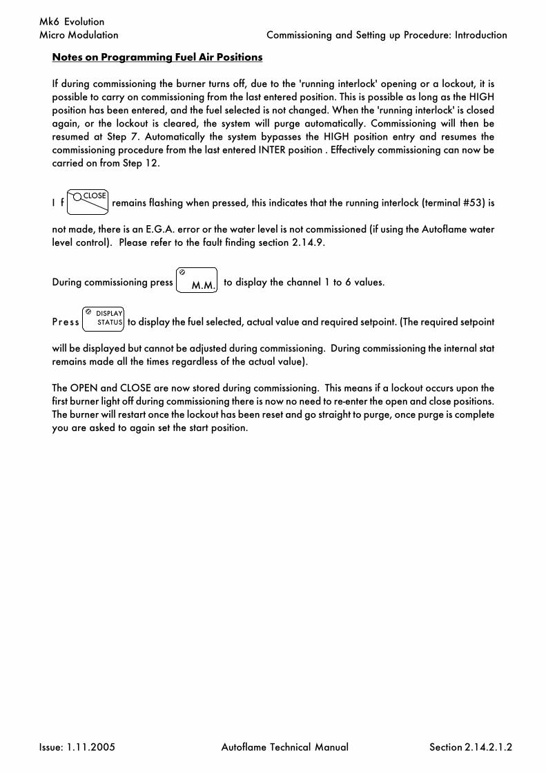
I f remains flashing when pressed, this indicates that the running interlock (terminal #53) is
not made, there is an E.G.A. error or the water level is not commissioned (if using the Autoflame waterlevel control). Please refer to the fault finding section 2.14.9.
During commissioning press to display the channel 1 to 6 values.
Press to display the fuel selected, actual value and required setpoint. (The required setpoint
will be displayed but cannot be adjusted during commissioning. During commissioning the internal statremains made all the times regardless of the actual value).
The OPEN and CLOSE are now stored during commissioning. This means if a lockout occurs upon thefirst burner light off during commissioning there is now no need to re-enter the open and close positions.The burner will restart once the lockout has been reset and go straight to purge, once purge is completeyou are asked to again set the start position.
M.M.
121212
DISPLAYSTATUS
123123123
2.14.2.1.2
Commissioning and Setting up Procedure: Introduction
CLOSE

Micro Modulation
Issue: 1.11.2005 Autoflame Technical Manual Section
Mk6 Evolution
2.14.2.2 Programming Fuel Air Positions (Systems without E.G.A.)
CH1, CH2 etc refers to the rows of buttons with CH1 at the top.
Note: Throughout the commissioning procedure the COM l.e.d. is illuminated.
1. Ensure 'stat' control circuit is closed, i.e. ensure that there is an input on terminal #53.
2. Select fuel. CLOSE flashes. 'ENTER PASSWORD' is displayed.
Note: If fuel selected is being re-commissioned, press before COM l.e.d.stops flashing (five seconds).
3. Enter Access Code. Adjust the numbers using the CH1 and CH2 buttons.
When numbers are set, press (CLOSE l.e.d. steady, ENTER flashes)
4. “SYSTEM ACTIVATE, WATER LEVEL CONFIGURE” is displayed.
On this password screen, it is necessary to set both CH1 and CH3. These are both set to #3 if theAutoflame water level system is to be active. Alternatively, these are both set to #7 for Mk6 usewithout the water level system. It is also necessary to set the CH5 value for First Out Annunciation.Set this to #0 to disable the First Out Annunciation, #1 to display the First Out Annunciation (butnot to lock out) and to #2 to enable First Out Annunciation, i.e. burner locks out.
Then press
5. The display indicates angular position of servo motors. After the internal checks are made (CLOSE
flashes). Press to start entering the close position.
6. Use CH1 to CH4 (as optioned) buttons to set positioning motors to 0.0.
P res s (OPEN flashes).
7. Press (OPEN steady, ENTER MEMORY flashes).
8. Use CH1 to CH4 buttons to set positioning motors to their fully open positions.
This is nominally 90.0 for gas butterfly valves and burner air dampers, but may be set to lessthan 90.0 degrees if there are mechanical stops/limits.
Press (System purges, at end of purge START flashes).
COM
CLOSE
2.14.2.2.1
Commissioning and Setting up Procedure: Programming Fuel/Air Positions
ENTER
MEMORY
ENTER
MEMORY
OPEN
ENTER
MEMORY
CLOSE

Micro Modulation
Issue: 1.11.2005 Autoflame Technical Manual Section
Mk6 Evolution
HIGH
ENTER
MEMORY
INTER START
ENTER
MEMORY
RUN
2.14.2.2.2
Commissioning and Setting up Procedure: Programming Fuel/Air Positions
9. P res s (START steady, ENTER MEMORY flashes).
**WARNING** Do not enter START position before reducing fuel input. Thiscould result in a potentially dangerous situation
10. Use CH1 to CH6 to set positioning motors to positions where ignition cantake place.
11. Pres s (Burner ignites, HIGH flashes).
12. Pres s (HIGH steady, ENTER MEMORY flashes).
13. Use CH1 and CH6 to set maximum firing input (it is not possible to exceed the OPEN
position values). Always increase the air first followed by the fuel angular positions.
14. Pres s (INTER, or INTER and START flash).
Note: Only INTER flashes if the number of INTER positions entered so far is less than or equalto three, thereafter INTER and START flash.
15. Pres s o r (INTER or START steady, ENTER MEMORY flashes).
16. Use CH1 to CH6 (as optioned) to reduce the positions. Always reduce the fuel
first followed by reducing the air angular position.
If present position is an INTER position, go back to 14, otherwise proceed further.
15. Pres s . At this point all commissioning data is permanently stored. (After a short
pause RUN flashes).
16. Pres s to set system into normal modulating mode.
START
ENTER
MEMORY

Micro Modulation
Issue: 1.11.2005 Autoflame Technical Manual Section
Mk6 Evolution
Setting Positioning Motors
Autoflame supply three standard sizes of positioning motors - small, large and industrial. All can be usedfor positioning fuel and air dampers.Both types can be configured to drive clockwise or counter clockwise to open a valve or damper.
Layout of small positioning motor, refer to Section 2.14.2.3.3Layout of large positioning motor, refer to Section 2.14.2.3.3Layout of industrial positioning motor, refer to Section 8.10
Viewing the shaft end-on, from the potentiometer end, all positioning motors drive in a clockwisedirection if power is applied between the LIVE and CW terminals, and counter clockwise if the poweris applied between the LIVE and CCW terminal.
The operation of fuel valves and air dampers is often such that they open in a clockwise direction. Ifthe operation needs to be reversed, it is necessary to swop various wiring connections between theM.M. and the positioning motor(s). An example of reversing the operation of a fuel valve is shown infigure B, section 2.14.2.3.4. Figure A shows the connections for normal operation.
Set Up Procedure
Before a burner is fired it is essential to set up each Micro Modulation positioning motor.
A tamper proof screwdriver is required (these can be ordered from Autoflame).
Usually control valves/air dampers that the positioning motors drive, move through up to 90 degreesangular. The M.M. system has the ability to drive valves through up to 96 degrees. Please contactAutoflame technical department for advice on applications for ranges greater than 90 degrees.
All readings displayed on the M.M. are in degrees angular. It is necessary to adjust the potentiometerin the positioning motor assembly so that the M.M. reads 0.0 when the relevant valve/damper is at itsfully closed position. The technician must physically check the mechanical position of the dampers andvalves. DO NOT ASSUME THEY HAVE BEEN PREVIOUSLY SET CORRECTLY.
To set up a positioning motor, first ensure option 12 is set to 0, (this prevents E.G.A. errors from allowingcontinuation). Put the M.M. into the commissioning mode so that the CLOSE l.e.d. is steady and theENTER l.e.d. flashes (see section on commissioning). By doing this it is possible to position the valve/damper mechanically by using the appropriate up and down buttons.
**WARNING** Electrical Connections are live/hot.
Remove the positioning motor cover.
2.14.2.3.1
Commissioning and Setting up Procedure: Setting Positioning Motors

Micro Modulation
Issue: 1.11.2005 Autoflame Technical Manual Section
Mk6 Evolution
For air positioning motor(s) carry out the following procedure:
Use the up/down buttons for the relevant air damper to position the air damper to its physically closedposition. Loosen the two tamper proof screws just sufficiently to enable the potentiometer to rotate.Rotate the potentiometer clockwise or counter clockwise until the relevant display window reads 0.0.Tighten the two tamper proof screws gently until the potentiometer is secure. Do not overtighten thescrews. Check that the display still reads 0.0. If not repeat the adjustment process.
For fuel positioning motor(s) carry out the following procedure:
On Autoflame gas, oil and gas/oil combination valves it is necessary to remove the positioning motor.Manually position the oil/gas valve slot to its closed position. Observe the position of the drive pin onthe positioning motor. Use the relevant up/down buttons to position the pin so that when the positioningmotor is reassembled to the valve it is in line with the slot. Reassemble the positioning motor to the valve,loosen the two tamper proof screws and proceed to adjust the potentiometer position until 0.0 isdisplayed. Use the external position indicator to ensure the valve is in the fully closed position.
Important Note for Autoflame valves:
On threaded valves, the pin on the top of the valve is 90 degrees opposite from the position of thebutterfly valve.
On flanged valves, the pin on the top of the valve is in line with the position of the butterfly valve.
For both valves the external visual position indicator is in line with the position of the butterfly valve.
Regardless of the type of valve being used, the servomotor is dispatched from the factory with thepotentiometer in the zero position. The same servomotor will be correct for both types of valve, as theservomotor for the threaded valve is mounted at 90 degrees different from the flanged valve.
2.14.2.3.2
Commissioning and Setting up Procedure: Setting Positioning Motors

Micro Modulation
Issue: 1.11.2005 Autoflame Technical Manual Section
Mk6 Evolution
Small Positioning Motor
Commissioning Procedure: Positioning Motors
Large Positioning Motor
2.14.2.3.3
W
+-
POSITIONING MOTOR
ADJUSTING CLIPSPOTENTIOMETER
P.C.B./4 FIXING POINTS M3
FIXING HOLES 5mm (7/32") DIA.
M4 EARTH STUD
POTENTIOMETER
TAMPER PROOF SCREWS
W
+-
L CW CCW
L CW CCW
TAMPER PROOF SCREWS
POTENTIOMETERP.C.B./2 FIXING POINTS M3
M4 EARTH STUD
POSITIONING MOTORFIXING HOLES 5mm (7/32") DIA.
POTENTIOMETER ADJUSTING CLIPS
-+
L
W
-+ W
CCW CW L
CWCCW
The servomotors shown are 230V in which the low voltage cables and mains voltage cables must enterthe servomotor through separate glands. For the 24V servomotors only one gland is required for boththe low voltage cables and mains voltage cables.

Micro Modulation
Issue: 1.11.2005 Autoflame Technical Manual Section
Mk6 Evolution
Positioning Motors Direction Change
2.14.2.3.4

Micro Modulation
Issue: 1.11.2005 Autoflame Technical Manual Section
Mk6 Evolution
2.14.2.3.5
Replacing the servomotor, servicing the servomotor and the importance of using theservomotors within the specified torque range.
Replacement- anytime that a servomotor is changed in the field, verification that the physical positionof the fuel/air/FGR valve/damper, e.t.c. is correct with the potentiometer feed back as displayed on theAutoflame controller, i.e. when the valve is completely closed as indicated on the valve/damper thenthe potentiometer reads zero angular degrees on the M.M. display. It must not be assumed that theoriginal commissioning engineer has the servomotor set in the correct position.
Servicing- it is good practice to periodically check the equipment and most notably the following forthe servomotors:
1- Overall mechanical soundness, i.e. look for corrosion or mechanical damage.2- Coupling and associated linkage is tight.3- Any associated set screws and fixings are secure.4- Mechanical pins, i.e. roll pins/split pins do not show any signs of corrosion and do not showindication of fatigue.5- When the burner is off and the power has been securely isolated, remove the servomotor from thedamper/valve, and ensure that the damper/valve does not require excessive torque to operate. Makesure that the servomotor is working within its recommended torque rating.6- Do not stand on the servomotors as this may cause internal damage to the PCB potentiometer leadingto a system failure.7- Do not remove the PCB inside the servomotor as this will affect the integrity of the repeatability andvoid any warranty that may apply.
Servomotor torque ratings- it is important that the servomotors are not used outside of theirspecified operating range.
Servomotor Part Number Rating
Small servomotor (MM10005) 0.89 ftlbs (1.2Nm)Large servomotor (MM10004) 11 ftlbs (15Nm)Industrial servomotor 5 (MM10070) 37 ftlbs (40Nm)Industrial servomotor 10 (MM10072) 72 ftlbs (98Nm)Industrial servomotor 20 (MM10074) 148 ftlbs (200Nm)Industrial servomotor 40 (MM10078) 295 ftlbs (400Nm)

Micro Modulation
Issue: 1.11.2005 Autoflame Technical Manual Section
Mk6 Evolution
2.14.2.4 Options
Important Note: The options and parameters must only be changed by factory trainedand certified technicians who have a thorough appreciation of the Autoflame combustionsystems and the combustion process in general. Anyone changing the options andparameters who does not have the correct training and understanding of these settings/adjustments may place themselves and others in a potentially dangerous situation.
If in doubt contact Autoflame technical support directly (+44 (0) 20 8695 2001).
To Select Options Mode.
CH1, CH2, CH3 refer to the rows of buttons respectively starting with CH1 at the top.
Option values can be changed by entering the option mode. The password must first be entered.To enter the password follow the steps listed:
Either deselect and then select fuel or power down and then up.
If system is already commissioned, press before the COM l.e.d. stops flashing.
If system is not already commissioned, commissioning mode will be set automatically.
“ENTER PASSWORD” is displayed.
Use the CH1 and CH2 to set the password codes. Then press
“SYSTEM ACTIVATE, WATER LEVEL CONFIGURE” is displayed.
On this password screen, it is necessary to set both CH1 and CH3. These are both set to #3 if theAutoflame water level system is to be active. Alternatively, these are both set to 7 for Mk6 use withoutthe water level system. It is also necessary to set the CH5 value for First Out Annunciation. Set this to0 to disable the First Out Annunciation, 1 to display the First Out Annunciation (but not to lock out) andto 2 to enable the First Out Annunciation, i.e. burner locks out.
Then press
On the following screen “Select to commission combustion fuel air ratio”
To select the 'SET OPTIONS' screen, press the CH1 simultaneously.
To change the option number use the CH2 buttons.
To change the value use the CH3 buttons.
Any number of option values can be changed when in option mode.
When changes have been made press .
All new option values are then permanently stored.
COM
CLOSE
ENTER
MEMORY
2.14.2.4.1
Commissioning and Setting up Procedure: Options
CLOSE
ENTER
MEMORY

Micro Modulation
Issue: 1.11.2005 Autoflame Technical Manual Section
Mk6 Evolution
1. 3 Boiler temperature/pressure sensor type:
3 Temperature sensor (MM10006 & 7) 20-390 C (50 - 730 F)4 Unused5 Unused6 Medium pressure sensor (MM10008) 2.0 - 23.0 bar (30 - 330 PSI)7 High pressure sensor (MM10009) 2.0 - 38.0 bar (30 - 550 PSI)8 Low pressure sensor (MM10010) 0.2 - 3.80 bar (1.5 - 55 PSI)9 Unused10 External temperature sensor (voltage input)- range set by parameters #52-5611 External pressure sensor (voltage input)- range set by parameters #52-56
2. 60 Motor travel speed during modulation: The value is not specific to a time/distance ratio. If the speed of the motor is too fast then increase this value. If tooslow, decrease the value. At times other than modulation the motors move at fullspeed or at the value set in option #75. Movement is limited by the slowestchannel, i.e. slowest moving motor.
5-240 Adjustment Range 5 = 43 seconds from 00 to 900
60 = 120 seconds from 00 to 900
240 = 390 seconds from 00 to 900
3. 0 Unused: This option only applies to the mini Mk5.
4. 0 Unused: This option only applies to the mini Mk5.
5. 1 Purge position: This selects the purge position. (Applicable to channels 1-4when selected; see options #67-70). VSD channels 5 & 6, if optioned, purge atopen position regardless of this option setting. It also applies to post purge ifoption #118 is set to a value greater than 0.
0 Selected channels purge at HIGH position (high fire position)1 Selected channels purge at OPEN position (full span of servomotor as entered
during commissioning)
Option N
o.
Facto
ry Setti
ng
Option Valu
e
Descrip
tion
2.14.2.4.2
Commissioning and Setting up Procedure: Options

Micro Modulation
Issue: 1.11.2005 Autoflame Technical Manual Section
Mk6 Evolution
6. 10 Proportional control (P): This option sets the proportional band. This is theoffset point at which the burner will begin to change modulation.
Example of proportional band offset: Required setpoint = 100 C, Proportionaloffset = 10 (i.e. option 6 set to value 10).
Proportional band: Value entered- Centigrade, Fahrenheit, Bar or PSI dependenton the type of control sensor used and display units selected- options #1 and #65.
5-250 If Centigrade, Fahrenheit or PSI units effective.0.5-25.0 If Bar units effective.
Note: Decreasing this value could lead to overshooting of the required setpoint.Increasing this value may cause the burner to modulate too early taking a longertime to reach the required setpoint.
7. 60 Integral control (I) time: Every n seconds 10% of the present offset fromsetpoint value is added or subtracted to the present proportional value. The valueof n is the number of seconds set in this option. It is possible to set this option to'off'. If 'off' is selected there will be no integral control. Parameter #106 enablesa % variation.
OFF-250 Seconds.
Note: Integral is equivalent to 'Reset'.
8. 1 Number of servomotor channels to be enabled: Channel "1" is alwaysenabled (Fuel Position Motor). Set option #8 to the number of additionalchannels required (Minimum of 1).
1 Channels 1 & 2 in use.2 Channels 1, 2 & 3 in use.3 Channels 1, 2, 3 & 4 in use.
Note: If option #8 is changed after commissioning then the M.M. unit will needto be recommissioned unless this option is returned to its previous value.
Option N
o.
Facto
ry Setti
ng
Option Valu
e
Descrip
tion
2.14.2.4.3
Minimum Flame
Maximum Flame
Proportional Offset
90 C(202 F)
100 C(212 F)
Commissioning and Setting up Procedure: Options

Micro Modulation
Issue: 1.11.2005 Autoflame Technical Manual Section
Mk6 Evolution
2.14.2.4.4
Commissioning and Setting up Procedure: Options
9. 1 Internal stat operation: The 'internal stat' serves the purpose of turning theburner on and off according to the actual value relative to the required setpoint.There are three settings for this option. The first keeps the 'internal stat' closed allthe time. In this instance, a 'working stat’ must be fitted to the boiler. The secondsetting opens the 'internal stat' at an offset above the required setpoint and closesit at an offset below the required setpoint. The third setting opens the 'internal stat'at an offset above the required setpoint and closes it at an offset also above therequired setpoint. The following diagrams illustrate this operation. The offsetvalues are set in options #10 and #11.
0 Internal stat always closed.1 Burner starts below required setpoint.2 Burner starts above required setpoint.
10. 3 Offset above required setpoint at which the burner is stopped:(Only relevant if option #9 is set to 1 or 2).
2-50 If Centigrade, Fahrenheit or PSI units effective.0.2-5.0 If Bar units effective.
11. 3 Offset below/above required setpoint at which the burner isstarted:(Only relevant if option #9 is set to 1 or 2).
2-50 If Centigrade, Fahrenheit or PSI units effective.0.2-5.0 If Bar units effective.
Option N
o.
Option Valu
e
Descrip
tion
Offset = 3 (value set in option #11)
Option #9 = 2, example using 100 C (212 F). Required setpoint.
Option #9 = 1, example using 100 C (212 F). Required setpoint.
Burner stops at this point and above
Required Value 100 C(212 F)
97 C(209 F)
103 C(215 F)
Burner starts at this point and below
Required Value 100 C(212 F)
103 C(215 F )
106 C(218 F)
Burner starts at this point and below
Burner stops at this point and above
Offset = 6 (value set in option #10)
Offset = 3 (value set in option #11)
Offset = 3 (value set in option #10)

Micro Modulation
Issue: 1.11.2005 Autoflame Technical Manual Section
Mk6 Evolution
12. 0 E.G.A. options: If this option has a setting 1/2/3/4/5/6/8/9 then the E.G.A.will trim and the burner must be commissioned with the E.G.A. operational. Thetrim is applied to channel 2 or 5, dependent on the setting of option #76.
0 E.G.A. not optioned.1 If an E.G.A. error occurs then the burner will continue to fire. The servomotors will
return to the original commissioned fuel/air ratio and the trim function will not beoperational until the E.G.A. error is reset. No combustion/single point changescan be made whilst the E.G.A. is in an error condition. Terminal #79 is energisedin the event of an E.G.A. error.
2 If an E.G.A. error occurs then the burner will stop firing. The burner will not startuntil the E.G.A. error has been cleared and the E.G.A. is inside its operatingtemperature range. Terminal #79 is energised in the event of an E.G.A. error.
3 Same as 1, except terminal #79 is not energised in the event of an E.G.A. error.4 Same as 2, except terminal #79 is not energised in the event of an E.G.A. error.5 Same as 1, plus the combustion limits are also tested (options #19-27).6 Same as 2, plus the combustion limits are also tested (options #19-27).7 System commissioned on M.M. only- E.G.A. used only for monitoring and display
purposes.8 Same as 5, except terminal #79 is not energised in the event of an E.G.A. error.9 Same as 6, except terminal #79 is not energised in the event of an E.G.A. error.
Note: If the E.G.A. is removed for servicing or this option is set to 0 or7, then any single point changes made during this time will result incomplete re-commissioning when this option is implemented again.
13. 0 0-30 Reset options to original factory settings: To reset all of the options backto their original factory set values, set option #13 to 26 and press enter.
14. 0 Twin burner application: Twin burner operation enables two burners to runat the same time and with the same firing rate. The identification numbers must beset for each M.M. unit, e.g. 1 and 2 (see option #33).
0 Normal single burner operation.1 Twin burner operation for twin furnace firetube applications- Both burners always
fire simultaneously. If one of the burners develops a fault, then both burners areshut down. Only one load detector is required and this is connected to the oddnumbered M.M. unit.
2 Twin burner operation for common furnace watertube applications- Both burnerswill fire simultaneously or independently. If both burners are firing then they willsynchronise together and fire at the same firing rate. If an error/lockout occurson one burner then the other burner will continue to fire independently. Two loadsensors are required (one for each M.M. unit).
Note: If communications are lost then a flashing error 100 will appear whenviewing the M.M. screen if option #14 is set to 1.
Option N
o.
Facto
ry Setti
ng
Option Valu
e
Descrip
tion
2.14.2.4.5
Commissioning and Setting up Procedure: Options

Micro Modulation
Issue: 1.11.2005 Autoflame Technical Manual Section
Mk6 Evolution
15. Unused:
16. 0 Lead/lag (IBS) and D.T.I: A lead boiler can be selected by connecting linevoltage to terminal #88 on the appropriate M.M. Only 1 M.M. may be selectedas lead boiler at a time or the sequencing will not operate. The lead boiler canbe selected via the D.T.I. However, for this to be effective all the M.M. units onthe system must have terminal #88 volt free. Line voltage on terminal #88overrides the D.T.I. command.
0 No sequencing. M.M. units still communicate and can be seen on the D.T.I.1 Sequencing enabled- the M.M. unit will respond to sequencing commands.2 Setpoint & enable/disable commands accepted from D.T.I.3 Both of 1 & 2.
Note: Accurate fuel flow metering must be entered for sequencing to operate.A RS485 data cable (BELDON9501) must be connected between each M.M. unit(see section 6.11.1 for correct connection)
17. 0 NO & CO displayed when running on oil: If fuels 2 or 3 are selected, thenthe displaying of CO & NO can be on or off. This option is only relevant if anE.G.A. is operational on the system. The pinch valve settings must also bechanged in the E.G.A. in order for CO & NO to be displayed.
0 NO & CO display blanked- not displayed.1 NO & CO is displayed normally.
18. 1 Carry forward of trim: When the system modulates, the correction that maybe existing on the air damper position can be carried forward. This option is onlyrelevant if an E.G.A. is operational on the system.
0 No carry forward of trim.1 Trim carried forward.
19. 0 Upper offset limit % O2:E.G.A. limits: Options #19-27 are only relevant if an E.G.A. is operational onthe system. Option #12 must be set to 5/6/8 or 9 if any of the following limitchecks are to be invoked. This is an offset from the commissioned values.
0-10.0 % O2.
20. 0 Upper offset limit % CO2:0-10.0 % CO2
21. 0 Upper offset limit ppm CO:0-200 ppm CO
Option N
o.
Facto
ry Setti
ng
Option Valu
e
Descrip
tion
2.14.2.4.6
Commissioning and Setting up Procedure: Options

Micro Modulation
Issue: 1.11.2005 Autoflame Technical Manual Section
Mk6 Evolution
22. 0 Lower offset limit % O2:0-10.0 % O2
23. 0 Lower offset limit % CO2:0-10.0 % CO2
24. Unused:
25. 0 Absolute value % O2: System checks for O2 values lower than value specifiedin this otion regardless of the commissioned values.
0-20.0 % O2
26. 0 Absolute value % CO2: System checks for CO2 values higher than valuespecified in this option regardless of the commissioned values.
0-20.0 % CO2
27. 0 Absolute value ppm CO: System checks for CO readings higher than valuespecified in this option regardless of the commissioned values.
0-200 ppm CO
28. 20 Trim threshold: This option is only relevant if an E.G.A. is operational on thesystem. The value set in this option is subtracted from the required setpoint. If theactual value is below the offset then the E.G.A. will not operate. If the trim is tobe effective at all times then set the value to zero. This option must also be set tozero for the E.G.A. to operate when external modulation is optioned.
0-50 If Centigrade, Fahrenheit or PSI units effective.0-5.0 If Bar units effective.
Note: No single point changes can be made if the actual value is below the offsetvalue.
29. 1 Golden start: See section 2.14.12. Parameter #15- sets the time the golden startis maintained from the ignition point.
0 Golden Start operates.1 Golden Start does not operate.
30. 50 D.T.I.- Required setpoint minimum limit: If the system is being used with aD.T.I. a maximum and minimum limit for the required setpoint must be set. If a valueis received from the D.T.I, that is outside these limits, it will be ignored and thesystem uses its previous required setpoint. Practical range is limited to range ofsensor selected.
5-9990 If Centigrade, Fahrenheit or PSI units effective.0.5-999.5 If Bar units effective.
Option N
o.
Facto
ry Setti
ng
Option Valu
e
Descrip
tion
2.14.2.4.7
Commissioning and Setting up Procedure: Options

Micro Modulation
Issue: 1.11.2005 Autoflame Technical Manual Section
Mk6 Evolution
31. 100 D.T.I.- Required setpoint maximum limit:
5-9990 If Centigrade, Fahrenheit or PSI units effective.0.5-999.5 If Bar units effective.
32. 20 Trim delay: After ignition the E.G.A. does not sample for the period of time setin this option (only relevant if E.G.A. is operational on system). This allows forthe combustion to stabilise before sampling commences. The timing starts at theignition point.
0-250 Period (seconds) after ignition no sampling takes place.
33. 1 M.M. Identification: The identification number must be set on all M.M. unitsin the boiler house. If not, then problems will occur with sequencing/twin burnerand with the D.T.I. communications. Each unit must have a different ID number.
1-10 Identification number.
34. 5 Rating of burner:
1-999 See option #77 for units.
35. 10 Sequence scan time: This is the time period that the M.M. controlling the lead/lag (sequencing) requests information from the other M.M. units to check whetherload demand is satisfied.
1-100 Sequence Scan time (minutes).
36. 0 E.G.A. sensor selection: Available when using an E.G.A. system fitted withNO/SO2 sensors. The following option is for selecting the type of sensors used.The pinch valve configuration must also be checked in the E.G.A. unit.
SO2 NO0 Off Off1 Off On2 On Off3 On On
37. 0 Derivative control (D) time interval: The time interval between the controllercomparing the actual value and the required setpoint value (derivative is equiva-lent to 'Rate').
0 (0=off)1-200 Seconds.
Option N
o.
Facto
ry Setti
ng
Option Valu
e
Descrip
tion
2.14.2.4.8
Commissioning and Setting up Procedure: Options

Micro Modulation
Issue: 1.11.2005 Autoflame Technical Manual Section
Mk6 Evolution
38. 2 Derivative control (D) deadband: The deadband is the margin above andbelow the required setpoint within which no derivative control occurs.
0-15 If Centigrade, Fahrenheit or PSI units effective.0-1.5 If Bar units effective.
39. 10 Derivative control (D) response sensitivity:
The sensitivity value indicates the amount of percentage firing rate increase ordecrease that is inflicted by the derivative action, e.g. if the chosen value was 10%then 10% of the maximum firing rate would be added to the existing rate of fire,i.e. if the burner was firing at 50% load and the derivative action was triggered thefiring rate would increase by 10+50 to 60%.
The following is an example of the above control philosophy in action:
Note: “Time Between Readings” set to 20 seconds.“Deadband” set to 2°C (2°F.)"Response Sensitivity” set to 10%.
Setpoint Information:“Required Setpoint” set to 90°C (190°F.)“Actual Value” reads 86°C (186°F.)
Firing Rate Information:Burner firing at 50% of capacity.
In the example situation there has been 4°C (4°F) drop in temperature below therequired setpoint. The deadband is set at 2°C (2°F.), therefore the derivativeaction will be triggered as the deviation from the required setpoint is in excess of2°C (2°F.). In this example 10% will be added to the 50% firing rate resultingin an increase in firing rate to 60% of capacity.The “Time Between Readings” is set for 20 seconds and if after this time intervalthe actual value is not within the 2°C (2°F) deviation from the required deadbandanother 10% would be added to the 60% firing rate which would result in a 70%firing rate.By careful selection of “Time Between Readings”, “Deadband” and “ResponseSensitivity” an ideal response to rate of change over time can be configured.The control philosophy detailed operates inversely if the “Actual” temperatureexceeds the required setpoint and is outside the “Deadband”.To enable or switch on the Derivative action the “Time Between Readings” mustbe set in excess of 10 seconds.
1-100 %
Option N
o.
Facto
ry Setti
ng
Option Valu
e
Descrip
tion
2.14.2.4.9
Commissioning and Setting up Procedure: Options

Micro Modulation
Issue: 1.11.2005 Autoflame Technical Manual Section
Mk6 Evolution
40. 0 Warming facility for low pressure steam sequencing: For lead/lag(sequencing) applications where check (non-return) valves are not installed, it isnot possible to use a phantom setpoint to keep the boilers in a standby warmingcondition. Therefore, the facility exists to install a thermostat (aquastat) in theboiler shell. The thermostat will input 230V/120V on terminal #93 and thisinitiates warming (see option #41). The boiler will remain in a warming statebased on the settings for options #53/54.
0 Disabled.1 Enabled.
41. 0 2/3 state steam sequencing: This option sets 2 states of operation for the lagboilers. Either one boiler is kept in a standby warming state and the other boilersare off, or all lag boilers are kept in a standby warming state and there are no offboilers.
0 3 state steam sequencing- LEAD, STANDBY, OFF, OFF, OFF, OFF...1 2 state steam sequencing- LEAD, STANDBY, STANDBY, STANDBY...
42. 20 Warming facility for medium/high pressure steam sequencing-phantom setpoint: For lead/lag (sequencing) applications where check (non-return) valves are installed, it is possible to use a phantom setpoint to keep theboilers in a standby warming condition. This value is an offset below the normalrequired setpoint. When the phantom setpoint is in effect, the burner is held at alow flame position.
0-100 If Centigrade, Fahrenheit or PSI units effective.0-10.0 If Bar units effective.
43. 5 Offset above phantom setpoint when the burner stops:
2-50 If Centigrade, Fahrenheit or PSI units effective.0.2-5.0 If Bar units effective.
44. 5 Offset below phantom setpoint when the burner starts up:
2-50 If Centigrade, Fahrenheit or PSI units effective.0.2-5.0 If Bar units effective.
Option N
o.
Facto
ry Setti
ng
Option Valu
e
Descrip
tion
2.14.2.4.10
Commissioning and Setting up Procedure: Options

Micro Modulation
Issue: 1.11.2005 Autoflame Technical Manual Section
Mk6 Evolution
45. 0 External modulation: When enabled the internal PID control is disabled andthe firing rate is set by an external controller applied to the appropriate inputterminals #7/8/9. This input control signal can be 0-10V, 2-10V, 4-20mA or 0-20mA representing low to high fire. A high limit stat must be fitted. A working statmay be required depending on the setting of this option.
0 Disabled.1 Enabled- no working stat facility (internal stat always closed- option #9), no local
display of pressure/temperature. Required setpoints not displayed. An externalworking stat is required.
2 Enabled- no working stat facility (internal stat always closed- option #9), loadsensor used for local display of pressure/temperature. Required setpoints notdisplayed. An external working stat is required.
3 Enabled- load sensor used for working stat facility and for local display ofpressure/temperature. Required setpoints displayed. External working stat notrequired.
Note: The fuel flow metering must be entered (option #57). If this is not enteredthen the M.M. will remain in the low flame hold state. Option #55 must be set tozero if option #45 is set to 1/2/3.
46. 0 Unused:
47. 0 Cold start routine: On burner start-up, if the actual value is below 30% of therequired setpoint, then the burner will be held at the low flame hold position forno longer than the number of minutes set in this option. If the boiler is at or below60% of its required setpoint then the burner firing rate would be held at 50% firingfor no longer than the number of minutes set in this option. When the actual valueexceeds the P band offset on the PID philosophy then the burner reverts to normalPID control. If the burner turns off then the timer is reset.
0 Off.1-2000 Number of minutes cold start operates.
Note: The cold start routine cannot be used with external modulation (options#45/55 are used).
48. 0 Flue gas recirculation- timer: This is the time that the M.M. channels(positioning motors/variable speed drives) are held at the FGR start positions,after which modulation then takes place. This timer starts at the end of mainflame proving. Also see parameter #90 regarding the commissioning of theFGR positions.
0-600 Seconds.
Option N
o.
Facto
ry Setti
ng
Option Valu
e
Descrip
tion
2.14.2.4.11
Commissioning and Setting up Procedure: Options

Micro Modulation
Issue: 1.11.2005 Autoflame Technical Manual Section
Mk6 Evolution
49. 0 Flue gas recirculation- offset: This is an offset from the required setpoint.The M.M. channels (positioning motors/variable speed drives are held at theFGR start positions until the actual value reaches the offset value below therequired setpoint.
0-50 If Centigrade, Fahrenheit or PSI units effective.0-5.0 If Bar units effective.
50. 0 Flue gas recirculation- flue gas temperature: The M.M. channels(positioning motors/variable speed drives) are held at the FGR start positionsuntil the flue gas temperature has reached 120°C or 248°F. (An E.G.A. mustbe present and optioned).
0 Not optioned.1 Optioned.
51. 0 Unused: Units of Temperature. See option #65.
52. 0 Unused: Units of Pressure. See option #65.
53. 1 Steam boiler sequencing burner ‘off’ time: The steam boiler typesequencing is enabled by setting option #1 to a respective pressure sensor.Options #42/43/44 are relevant to the "Standby" boiler operation.
1-200 Burner "Off" time (minutes) during warm up cycle.Intelligent boiler sequencing- steam boiler applications.
54. 5 Steam boiler sequencing burner 'on' time:
1-30 Burner "On" time (minutes) during warm up cycle.Intelligent boiler sequencing- steam boiler applications.
55. 0 Internal PID/external modulation selectible using terminal #88:(Cannot be used with lead lag/intelligent boiler sequencing)
0 Normal operation- internal PID.1 Terminal 88 = 0 V- internal PID.
Terminal 88 = Line voltage- external modulation. Thisoption also removes thereduced setpoint from the Mk.6 display if it is not a requirement.
Note: Option #45 must be set to zero if option #55 set to 1. Option #9 willbe used as set. If option #9 is set to zero the required setpoint is not displayed.
Option N
o.
Facto
ry Setti
ng
Option Valu
e
Descrip
tion
2.14.2.4.12
Commissioning and Setting up Procedure: Options

Micro Modulation
Issue: 1.11.2005 Autoflame Technical Manual Section
Mk6 Evolution
56. 1 Operation of alarm output for all system errors/lockouts andE.G.A. errors on terminal #79:
1 Relay normally off, on when alarm.2 Relay normally on, off when alarm.
Note: This is a switched neutral and not a voltage output terminal.
57. 0 Fuel flow metering: To set this option and initiate the fuel flow meteringprogram, the Enter button must be pressed when viewing this option.
0 No flow metering.1 Flow metering operates and recalibrated.2 Totalised fuel flow metering is reset to zero for the selected fuel.
58. 15 Unused:
59. 0 Unused:
60. 0 Hand/auto bumpless transfer operation:
0 Fuel valve goes directly to last set hand position.1 Hand position (taken on present fuel valve position when changing from auto to
hand operation).2 As 0, but hand position is not stored in permanent memory.
61. 1 Flow metering units fuel 1- gaseous:
0 Cubic feet.1 Cubic meters.2 DO NOT USE.3 DO NOT USE.4 DO NOT USE.
62. 3 Flow metering units fuel 2- liquid:
0 DO NOT USE.1 Lbs.2 Kilograms.3 Litres.4 US gallons.
Option N
o.
Facto
ry Setti
ng
Option Valu
e
Descrip
tion
2.14.2.4.13
Commissioning and Setting up Procedure: Options

Micro Modulation
Issue: 1.11.2005 Autoflame Technical Manual Section
Mk6 Evolution
63. 3 Flow metering units fuel 3- liquid:
0 DO NOT USE.1 Lbs.2 Kilograms.3 Litres.4 US gallons.
64. 1 Flow metering units fuel 4- gaseous:
0 Cubic feet.1 Cubic meters.2 DO NOT USE.3 DO NOT USE.4 DO NOT USE.
65. 0 Type of fuel flow metering:
0 Old fuel flow metering.1 Imperial fuel flow metering.2 Metric fuel flow metering.
66. 0 Unused:
67. 1 Channel 1 purge position: The following options tell the M.M. which channelsare to be included in the Purge sequence. See option #5 for purge position.
0 Channel 1 to purge position.1 Channel 1 to remain closed for purge.
68. 0 Channel 2 purge position:
0 Channel 2 to purge position.1 Channel 2 to remain closed for purge.
69. 0 Channel 3 purge position:
0 Channel 3 to purge position.1 Channel 3 to remain closed for purge.
70. 0 Channel 4 purge position:
0 Channel 4 to purge position.1 Channel 4 to remain closed for purge.
Option N
o.
Facto
ry Setti
ng
Option Valu
e
Descrip
tion
2.14.2.4.14
Commissioning and Setting up Procedure: Options

Micro Modulation
Issue: 1.11.2005 Autoflame Technical Manual Section
Mk6 Evolution
71. 0 Fuel 1- fuel type:
0 Natural gas.1 DO NOT ADJUST.2 DO NOT ADJUST.3 DO NOT ADJUST.4 DO NOT ADJUST.5 Fuel 1.
72. 1 Fuel 2- fuel type:
0 DO NOT ADJUST.1 Light distillate oil.2 Heavy fuel oil.3 DO NOT ADJUST.4/5 Fuel 2.
73. 1 Fuel 3- fuel type:
0 DO NOT ADJUST.1 Light distillate oil.2 Heavy fuel oil.3 DO NOT ADJUST.4/5 Fuel 3.
74. 0 Fuel 4- fuel type:
0 Natural gas.1 DO NOT ADJUST.2 DO NOT ADJUST.3 DO NOT ADJUST.4 DO NOT ADJUST.5 Fuel 4.
75. 0 Purge motor travel speed: During a purge sequence the motor travel speedcan be set independent of option #2. This effects all selected channels.
0 -100 0 = Quickest time.100 = Slowest time.
76. 0 Trim channel: If an E.G.A. is optioned, the trim can be applied to either Channel2 (positioning motor) or channel 5 (VSD). If trim on channel 5 is used, options#91/97 must be entered correctly.
0 Trim on channel 2.1 Trim on channel 5.
Option N
o.
Facto
ry Setti
ng
Option Valu
e
Descrip
tion
2.14.2.4.15
Commissioning and Setting up Procedure: Options

Micro Modulation
Issue: 1.11.2005 Autoflame Technical Manual Section
Mk6 Evolution
Option N
o.
Facto
ry Setti
ng
Option Valu
e
Descrip
tion
2.14.2.4.16
Commissioning and Setting up Procedure: Options
77. 0 Burner rating units: Display purposes only for fuel flow metering.
0 KW x 100 /hr 6 Btu x 1000 /hr1 Kg x 100 /hr 7 Hp x 10 /hr2 MW /hr 8 lbs x 1000 /hr3 Btu x 100 /hr 9 Btu x 1000 000 /hr4 Hp x 100 /hr5 lbs x 100 /hr
78. 0 Unused:
79. 0 Lowest required setpoint:
0-995 Minimum required setpoint allowed when O.T.C. optioned.See option #80 and parameter #88. Point A- see diagram in section 2.14.2.8.1.
80. 0 Outside temperature compensation:
0 Disabled.1 Enabled.
Note: A line voltage on terminal #93 invokes a 'Night Setback' offset value, seeoption #85.
81. 140 Maximum boiler required setpoint at minimum outside temperature:Point B- see diagram in section 2.14.2.8.1.
50-999 Value limited in accordance with sensor selected by option #1.
82. -30 Minimum outside temperature: Point C- see diagram in section 2.14.2.8.1.
-40 +40 For Centigrade.-40 +105 If Fahrenheit.
83. 65 Minimum boiler required setpoint at maximum outside temperature:
50-999 Value limited in accordance with sensor selected by option #1.
84. 30 Maximum outside temperature: Point D- see diagram in section 2.14.2.8.1.
-20 +40 For Centigrade.-4 +105 If Fahrenheit.

Micro Modulation
Issue: 1.11.2005 Autoflame Technical Manual Section
Mk6 Evolution
85. 10 Night setback 'depression' offset value: This offset is subtracted fromthe normal required setpoint and activated by a line voltage on terminal #93.
0-100 °C/°F/PSI.
86. 0 Channel 1 softened error checking select: Increases positioning error.fom 0.1° to 0.5° for an industrial servomotor.
0 CH1 normal positioning motor.1 CH1 industrial positioning motor/softened error checking.
87. 0 Channel 2 softened error checking select:
0 CH2 normal positioning motor.1 CH2 industrial positioning motor/softened error checking.
88. 0 Channel 3 softened error checking select:
0 CH3 normal positioning motor.1 CH3 industrial positioning motor/softened error checking.
89. 0 Channel 4 softened error checking select:
0 CH4 normal positioning motor.1 CH4 industrial positioning motor/softened error checking.
90. 0 VSD operation channel 5:
0 Not optioned.1 Optioned.
91. 0 Output from M.M. to VSD:
0 Output units displayed as 4-20 milliamps.1 Output units displayed as 0-10 volts.2 Output units displayed as hertz.
92. 25 Output low speed from M.M. to VSD: Same value as set on the VSD.
1-200 Hertz.
93. 50 Output high speed from M.M. to VSD: Same value as set on the VSD.
1-200 Hertz.
Option N
o.
Facto
ry Setti
ng
Option Valu
e
Descrip
tion
2.14.2.4.17
Commissioning and Setting up Procedure: Options

Micro Modulation
Issue: 1.11.2005 Autoflame Technical Manual Section
Mk6 Evolution
94. 2 Input signal to M.M. from VSD:
0 4-20 milliamps.1 0-10 volts.2 0-20 milliamps.
95. 0 Input units displayed:
0 Selected input signal.1 Hertz.
96. 0 Input low speed to M.M. from VSD: Same value as set on the VSD.
0-200 Hertz.
97. 50 Input high speed to M.M. from VSD: Same value as set on the VSD.
0-200 Hertz.
98. 0 Unused:
99. 0 Unused:
100. 0 VSD operation channel 6:
0 Not optioned.1 Optioned.
101. 0 Output from M.M. to VSD:
0 Output units displayed as 4-20 milliamps.1 Output units displayed as 0-10 volts.2 Output units displayed as hertz.
102. 25 Output low speed from M.M. to VSD: Same value as set on the VSD.
1-200 Hertz.
103. 50 Output high speed from M.M. to VSD: Same value as set on the VSD.
1-200 Hertz.
Option N
o.
Facto
ry Setti
ng
Option Valu
e
Descrip
tion
2.14.2.4.18
Commissioning and Setting up Procedure: Options

Micro Modulation
Issue: 1.11.2005 Autoflame Technical Manual Section
Mk6 Evolution
104. 2 Input signal to M.M. from VSD:
0 4-20 milliamps.1 0-10 volts.2 0-20 milliamps.
105. 0 Input units displayed:
0 Selected input signal.1 Hertz.
106. 0 Input low speed to M.M. from VSD: Same value as set on the VSD.
0-200 Hertz.
107. 50 Input high speed to M.M. from VSD: Same value as set on the VSD.
0-200 Hertz.
108. Unused:
109. Unused:
Option N
o.
Facto
ry Setti
ng
Option Valu
e
Descrip
tion
2.14.2.4.19
Commissioning and Setting up Procedure: Options

Micro Modulation
Issue: 1.11.2005 Autoflame Technical Manual Section
Mk6 Evolution
For safety reasons, options #110-150 alsohave to be entered in as parameters.It is the responsibility of the commissioningEngineer to ensure that all settings are set inaccordance with the appropriate standards,local codes and practices, e.t.c.
If the M.M. system is stuck in the ‘idle’ condition, it is likelythat options #110-150 are not identical to parameters#110-150. If the commissioning mode is entered, therelevant options/parameters not set correctly will bedisplayed at the bottom of the screen. If more than 1option/parameter is not set correctly, these will bedisplayed in numerical order, i.e. on entering thecommissioning mode again the next sequential option/parameter not set correctly will be displayed.
110. 1 Burner flame scanner type:
1 Internal non-permanent operation- standard scanner.2 Internal permanent operation- self-check scanner.
111. 0 Pilot:
0 Interrupted pilot.1 Intermittant pilot (expanding flame).
112. 40 Pre purge time:
05-300 Seconds/minutes- see option #135.
113. 3 Pre ignition time: Time ignition transformer is on before pilot gas valve opens.
3-5 Seconds.
114. 3 First safety time: Time pilot valve is open before UV is checked.
3-10 Seconds.
Option N
o.
Facto
ry Setti
ng
Option Valu
e
Descrip
tion
2.14.2.4.20
Commissioning and Setting up Procedure: Options

Micro Modulation
Issue: 1.11.2005 Autoflame Technical Manual Section
Mk6 Evolution
115. 3 Pilot prove time- pilot trial for ignition PTFI:
3-5 Seconds.
116. 3 Fuel 1 & fuel 4 (gas programs) second safety time- main trial forignition MTFI: Pilot/main valve overlap.(Not Applicable to expanding flame - see option #111).
3-10 Seconds.
117. 5 Main flame prove time: Time period from main valves open to burnermodulating- delay to modulation.
5-20 Seconds.
118. 0 Post purge time :
0-100 Seconds (0- No post purge) U.V. Not checked during post purge. See alsooption #135.
119. 10 Control box recycle time: Time delay from burner shut down to startup.
3-120 Seconds.
120. 10 UV threshold:
5-50 Minimum Flame Signal Strength during pilot. (At all other times UV thresholdis fixed at 5).
121. 5 Delay from start of pre purge after which air switch checked:
5-10 Seconds.
122. 0 Flame switch operation: If this option is enabled Terminals 85/86 areused in conjunction with a flame switch to monitor the presence of a flame.
0 Disabled - normal UV scanner operation.1 Enabled - flame switch operation.
123. 3 Fuel 2 & fuel 3 (oil programs) second safety time- main trial forignition MTFI: Pilot/main flame overlap.(Not Applicable to expanding flame - see option #111).
3-15 Seconds.
Option N
o.
Facto
ry Setti
ng
Option Valu
e
Descrip
tion
2.14.2.4.21
Commissioning and Setting up Procedure: Options

Micro Modulation
Issue: 1.11.2005 Autoflame Technical Manual Section
Mk6 Evolution
124. 1 Gas valve proving pressure sensor type:
0 Nominal range 0–25" w.g./ 0–65 mbar/ 0–1 psi (Sensor MM60006)Note. PSI display not available with this sensor
1 Nominal range 0–135"w.g./ 0–340 mbar/ 0–5 psi (Sensor MM60008)2 Nominal range 0–300"w.g./ 0–750 mbar/ 0–11 psi (Sensor MM60011)3 Nominal range 0–550"w.g./ 0–1380 mbar/ 0–20 psi (Sensor MM60012)4 Nominal Range 0-1650”w.g/0-4125 mbar/0-60psi (Sensor MM60014)
125. 0 Gas valve proving & high-low pressure limit checked- fuel 1:
0 Not checked on fuel 1.1 Gas valve proving on + high/low pressure limits (see options #136/137).2 Do not select.3 Gas high/low pressure Limit. If options #136/137 are set to 0, then the online
values are displayed only.
126. 0 Fuel 2/oil high-low pressure limit checked- fuel 2:
0 Not checked on fuel 2.1 Do not select.2 Oil high/low pressure limit. If options #139/140 are set to 0, then the online
values are displayed only.3 Do not select.
127. 0 Fuel 3/oil high-low pressure limit checked- fuel 3:
0 Not checked on fuel 3.1 Do not select.2 Oil high/low pressure limit. If options #139/140 are set to 0, then the online
values are displayed only.3 Do not select.
128. 0 Gas valve proving & high-low pressure limit checked- fuel 4:
0 Not checked on fuel 4.1 Gas valve proving on + high/low pressure limits (see options #136/137).2 Do not select.3 Gas high/low pressure limit. If options #139/140 are set to 0, then the online
values displayed only.
129. 0 VPS operation: This option must be set to 0 during commissioning. Oncecommissioning is complete it can then be set to 1.
0 VPS operates before burner start up.1 VPS operates after burner run (low gas not checked before burner starts).
Option N
o.
Facto
ry Setti
ng
Option Valu
e
Descrip
tion
2.14.2.4.22
Commissioning and Setting up Procedure: Options

Micro Modulation
Issue: 1.11.2005 Autoflame Technical Manual Section
Mk6 Evolution
130. 2 Gas valve proving:
0 Two valve gas valve proving.1 Three valve gas valve proving. Vent valve normally closed.2 Three valve gas valve proving. Vent valve normally open.
3 Two valve gas valve proving- single valve pilot.4 Three valve gas valve proving- single valve pilot. Vent valve normally closed.5 Three valve gas valve proving- single valve pilot. Vent valve normally open.
131. 0 Gas pressure units: PSI not available for MM60006 - see option #124.
0 "wg (inches water gauge).1 mbar (millibars).2 psi (pounds per square inch) - units displayed to 2 decimal places.
132. 20 Gas valve proving time:
10-30 Seconds.
133. 5.0 Maximium pressure change allowed during proving time:
0.1-5 "wg/ 0.2-12.4mbar/ psi not available (Sensor MM60006)0.4-25.2 "wg/ 1.1-63 mbar/ 0.02 - 0.91 psi (Sensor MM60008)1-56 "wg/ 2.5-140 mbar/ 0.04 - 2.03 psi (Sensor MM60011)1.9-103 "wg/ 4.6-356 mbar/ 0.07 - 5.16 psi (Sensor MM60012)
Note: Option #124 for pressure sensor range in use, default value willchange accordingly. See Section 2.14.2.6.2.
134. 3 VPS valve opening time:
3-20 Seconds.
135. 0 Change purge time:
0 Seconds.1 Minutes.2 NFPA post purge- post purge time in seconds is set in option #118.
Note: If this option is set to 2 (NFPA post purge) then option #118 must be setto a value of 15 or greater otherwise a lockout warning message will occur.During the NFPA post purge the elements will remain at the position that theywere in during normal shutdown or lockout (see also options #67-70). The NFPApost purge will occur under any normal shutdown or lockout at any point in thestart up/firing sequence.
Option N
o.
Facto
ry Setti
ng
Option Valu
e
Descrip
tion
2.14.2.4.23
Commissioning and Setting up Procedure: Options
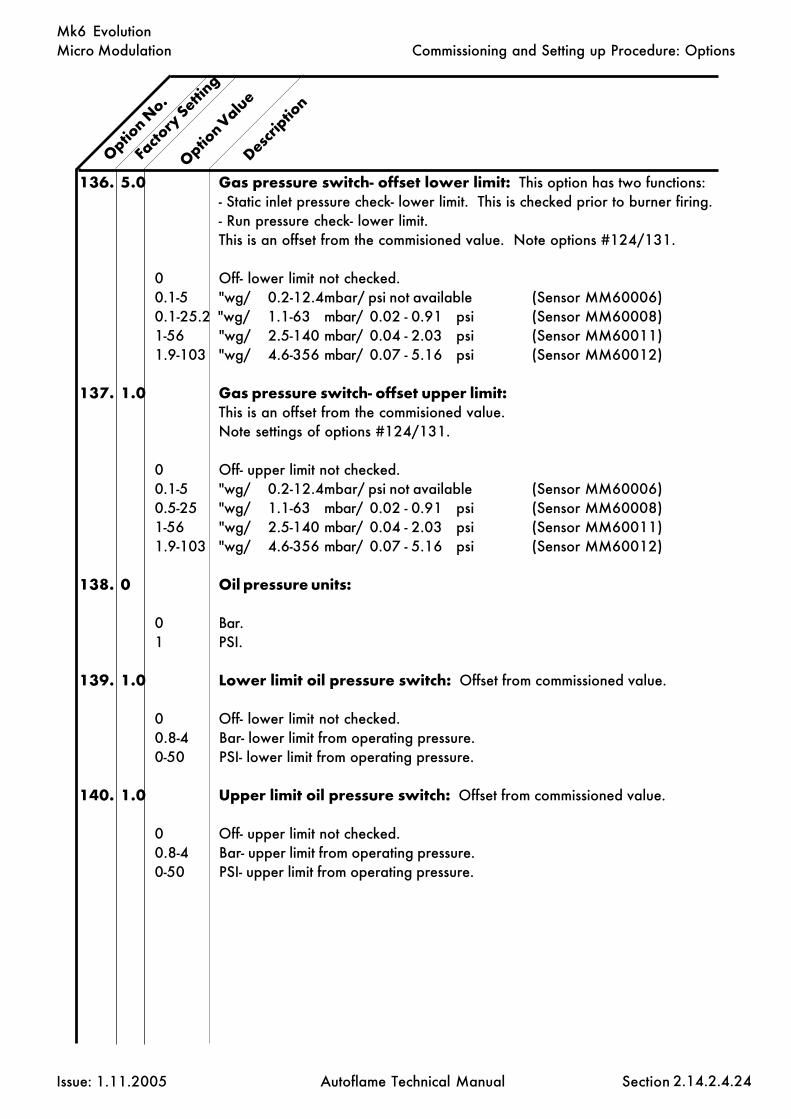
Micro Modulation
Issue: 1.11.2005 Autoflame Technical Manual Section
Mk6 Evolution
Option N
o.
Descrip
tion
Facto
ry Setti
ng
Option Valu
e
136. 5.0 Gas pressure switch- offset lower limit: This option has two functions:- Static inlet pressure check- lower limit. This is checked prior to burner firing.- Run pressure check- lower limit.This is an offset from the commisioned value. Note options #124/131.
0 Off- lower limit not checked.0.1-5 "wg/ 0.2-12.4mbar/ psi not available (Sensor MM60006)0.1-25.2 "wg/ 1.1-63 mbar/ 0.02 - 0.91 psi (Sensor MM60008)1-56 "wg/ 2.5-140 mbar/ 0.04 - 2.03 psi (Sensor MM60011)1.9-103 "wg/ 4.6-356 mbar/ 0.07 - 5.16 psi (Sensor MM60012)
137. 1.0 Gas pressure switch- offset upper limit:This is an offset from the commisioned value.Note settings of options #124/131.
0 Off- upper limit not checked.0.1-5 "wg/ 0.2-12.4mbar/ psi not available (Sensor MM60006)0.5-25 "wg/ 1.1-63 mbar/ 0.02 - 0.91 psi (Sensor MM60008)1-56 "wg/ 2.5-140 mbar/ 0.04 - 2.03 psi (Sensor MM60011)1.9-103 "wg/ 4.6-356 mbar/ 0.07 - 5.16 psi (Sensor MM60012)
138. 0 Oil pressure units:
0 Bar.1 PSI.
139. 1.0 Lower limit oil pressure switch: Offset from commissioned value.
0 Off- lower limit not checked.0.8-4 Bar- lower limit from operating pressure.0-50 PSI- lower limit from operating pressure.
140. 1.0 Upper limit oil pressure switch: Offset from commissioned value.
0 Off- upper limit not checked.0.8-4 Bar- upper limit from operating pressure.0-50 PSI- upper limit from operating pressure.
2.14.2.4.24
Commissioning and Setting up Procedure: Options

Micro Modulation
Issue: 1.11.2005 Autoflame Technical Manual Section
Mk6 Evolution
Option N
o.
Descrip
tion
Facto
ry Setti
ng
Option Valu
e
141. 0 Purge air pressure proving: During pre purge this option enables theair proving pressure to be tested at a value independent of option #149.Option #148 must be set.
0 Off- no purge air pressure proving.0-26.9 “wg.0.1-67 mbar.
Note: If option #141 is set without option #148 a lockout will occur whenthe system starts to purge. The lockout message displayed warns that option#141 is incorrectly set.
142. 0 Unused:
143. 0 Unused:
144. 0 Unused:
145. 0 Autoflame air pressure sensor:
0 Autoflame air pressure sensor not optioned.1 Autoflame air pressure sensor optioned 0-1 PSI (Sensor MM60005)2 Autoflame air pressure sensor optioned 0-2 PSI (Sensor MM60013)
146. 0 Air pressure units:
0 "wg.1 mBar.
147. 0 Air sensor error checking window: Only active during modulation(error #82). The burner will shut down if outside the window.
0 No error checking.0 - 3 "wg (maximum = +/- 3 "wg).0 - 7.5 mbar (maximum = +/- 7.5 mbar).
148. 0 Autoflame air proving selected:
0 Not used- requires external air proving switch on terminal #54 (applies to all4 fuels).
1 Air proving- requires Autoflame air pressure sensor but no input on terminal#54 (applies to all 4 fuels).
2 Air proving- requires Autofame air pressure sensor and terminal #54 (appliesto all 4 fuels).
2.14.2.4.25
Commissioning and Setting up Procedure: Options

Micro Modulation
Issue: 1.11.2005 Autoflame Technical Manual Section
Mk6 Evolution
Option N
o.
Descrip
tion
Facto
ry Setti
ng
Option Valu
e
149. 0.3 Minimum air pressure proving value: Air pressure switch function.
0.3 - 4.9 " wg.1 - 12.5 mbar.
150. 0 Clear ALL commissioning data and gas/air sensor re-commission:
0 - 10 Range.5 Clear commissioning data- restore options/parameters to factory settings.7 Air sensor automatic recomission (see section 2.14.18.1 in the technical
manual for more information).8 Gas sensor automatic recommision (see section 2.14.18.2 in the technical
manual for more information).
For safety reasons, options #110 to 150 alsohave to be entered in as parameters.It is the responsibility of the commissioningEngineer to ensure that all settings are set inaccordance with the appropriate standards,local codes and practices, e.t.c.
2.14.2.4.26
Commissioning and Setting up Procedure: Options

Micro Modulation
Issue: 1.11.2005 Autoflame Technical Manual Section
Mk6 Evolution
2.14.2.5 Parameters
To Select Parameter ModeCH1, CH2, CH3 refer to the rows of buttons respectively starting with CH1 at the top.
Parameter values can be changed by entering the Parameter mode. The password must first be entered.To enter the password follow the steps listed:
Either deselect and then select fuel or power down and then up.
If system is already commissioned, press before the COM l.e.d. stops flashing.
If system is not already commissioned, commissioning mode will be set automatically.
“ENTER PASSWORD” is displayed.
Use the CH1 and CH2 to set the Password codes. Then press
“SYSTEM ACTIVATE, WATER LEVEL CONFIGURE” is displayed.
On this password screen, it is necessary to set both CH1 and CH3. These are both set to #3 if theAutoflame water level system is to be active. Alternatively, these are both set to #7 for Mk6 use withoutthe water level system. It is also necessary to set the CH5 value for First Out Annunciation. Set this to#0 to disable the First Out Annunciation, #1 to display the First Out Annunciation (but not to lock out)and to #2 to enable the First Out Annunciation, i.e. burner locks out.
Then press
On the following screen “Select to commission combustion fuel air ratio”
To select the 'SET PARAMETERS' screen, press and simultaneously.
To change the parameter number use the CH2 buttons.
To change the value use the CH3 buttons.
Any number of Parameter values can be changed when in Parameter mode.
When changes have been made press
All new Parameter values are then permanently stored.
N.B. The E.G.A. related parameters have the factory default settings from years oftesting on many fuels and applications. It is advised to be cautious when changing theseparameters, and is recommended not to do so.
COM
CLOSEOPEN
2.14.2.5.1
ENTER
MEMORY
Commissioning and Setting up Procedure: Parameters
CLOSE
ENTER
MEMORY
CLOSE
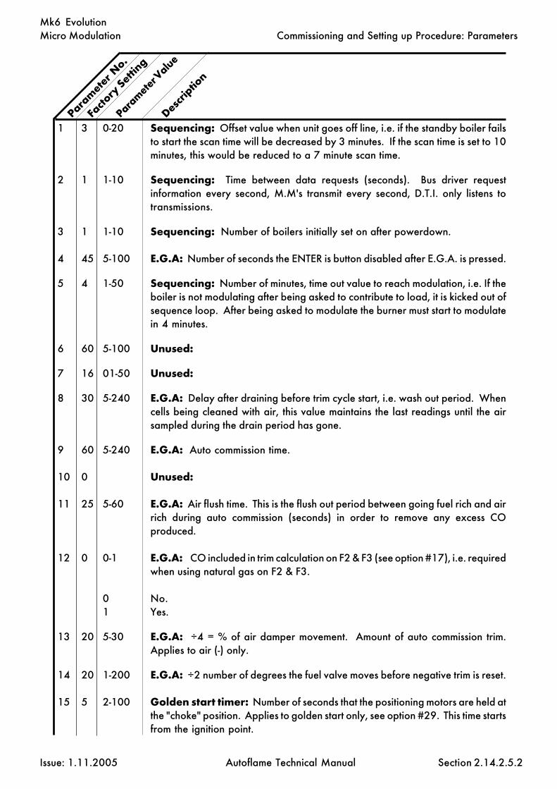
Micro Modulation
Issue: 1.11.2005 Autoflame Technical Manual Section
Mk6 Evolution
1 3 0-20 Sequencing: Offset value when unit goes off line, i.e. if the standby boiler failsto start the scan time will be decreased by 3 minutes. If the scan time is set to 10minutes, this would be reduced to a 7 minute scan time.
2 1 1-10 Sequencing: Time between data requests (seconds). Bus driver requestinformation every second, M.M's transmit every second, D.T.I. only listens totransmissions.
3 1 1-10 Sequencing: Number of boilers initially set on after powerdown.
4 45 5-100 E.G.A: Number of seconds the ENTER is button disabled after E.G.A. is pressed.
5 4 1-50 Sequencing: Number of minutes, time out value to reach modulation, i.e. If theboiler is not modulating after being asked to contribute to load, it is kicked out ofsequence loop. After being asked to modulate the burner must start to modulatein 4 minutes.
6 60 5-100 Unused:
7 16 01-50 Unused:
8 30 5-240 E.G.A: Delay after draining before trim cycle start, i.e. wash out period. Whencells being cleaned with air, this value maintains the last readings until the airsampled during the drain period has gone.
9 60 5-240 E.G.A: Auto commission time.
10 0 Unused:
11 25 5-60 E.G.A: Air flush time. This is the flush out period between going fuel rich and airrich during auto commission (seconds) in order to remove any excess COproduced.
12 0 0-1 E.G.A: CO included in trim calculation on F2 & F3 (see option #17), i.e. requiredwhen using natural gas on F2 & F3.
0 No.1 Yes.
13 20 5-30 E.G.A: ÷4 = % of air damper movement. Amount of auto commission trim.Applies to air (-) only.
14 20 1-200 E.G.A: ÷2 number of degrees the fuel valve moves before negative trim is reset.
15 5 2-100 Golden start timer: Number of seconds that the positioning motors are held atthe "choke" position. Applies to golden start only, see option #29. This time startsfrom the ignition point.
Param
eter N
o.
Facto
ry Setti
ng
Parameter V
alue
Descrip
tion
2.14.2.5.2
Commissioning and Setting up Procedure: Parameters

Micro Modulation
Issue: 1.11.2005 Autoflame Technical Manual Section
Mk6 Evolution
Parameter V
alue
16 12 1-50 E.G.A: Time between calibrations (÷ 2 = Hours). The E.G.A. calibrates every6 hours if the burner does not turn off.
17 3 0-10 E.G.A: Number of trims before an E.G.A. error is flagged when limits exceeded.Each Trim = 30 Seconds.
18 20 5-60 E.G.A: Trim amount during run ÷ by 2 = % of trim. This value cannot be setabove 20 (10%) or an ERROR 25 will occur.
19 1 0-1 Unused:
20 0 0-40 Reset parameters to original factory settings: To reset all of theparameters back to their original factory set values, set option #20 to 26 andpress enter.
21 0 Unused:
22 0 DTI: Do not adjust.
23 0 E.G.A: Trim- add air when CO present. When trim is taking place, if the O2 andCO2 appear on the air rich side but the CO appears on the fuel rich side then theair damper will open further to remove the CO.
0 Enabled.1 Disabled.
24 120 20-240 E.G.A: Calibration time (seconds).
25 30 5-100 E.G.A: Time between samples.
26 8 1-50 E.G.A: Number of samples per trim cycle.
27 25 0-255 E.G.A: Minimum operating temperature (÷ 5=deg C).
28 200 0-255 E.G.A: Maximum operating temperature (÷ 5=deg C).
29 0 0-10 Unused:
30 10 0-40 Filters load sensor readings: Temperature and pressure detectors.
0 No filtering.20 Maximum filtering.
31 0 0-1 Selects efficiency to be displayed:
0 English (USA/Canada- incorporates Hydrogen & moisture loss).1 European.
Param
eter N
o.
Facto
ry Setti
ng
Descrip
tion
2.14.2.5.3
Commissioning and Setting up Procedure: Parameters

Micro Modulation
Issue: 1.11.2005 Autoflame Technical Manual Section
Mk6 Evolution
32- Unused:37
38 254 0-255 M.M. password: Channel 1.
39 1 0-255 M.M. password: Channel 2.
40- Unused:43
44 0.4 0-40 E.G.A: O2 window inside which no further trim takes place.
45 0.2 0-20 E.G.A: CO2 window inside which no further trim takes place.
46- Unused:47
48 0.8 0.01- Integral control (I) threshold: This is a percentage below the required 0.99 setpoint to the proportional band offset at which point the integral control takes
effect, i.e. if the required setpoint is 100psi, option #6 = 10psi, parameter #48= 0.8, the integral control will take effect when the actual value is above 92psi.
49 0 0-1 Required setpoint: Set to 1 if required setpoint not to be stored permanentlyin memory. This is important to set if using parameter #72.
50- Unused:51
52 0 0-2 External load detector: Number of decimal points (please see table below).
53 0 0-9990 External load detector: Maximum value (please see table below).
54 0 0-100 External load detector: Maximum voltage (please see table below).
55 0 0-9990 External load detector: Minimum value (please see table below).
56 0 0-100 External load detector: Minimum voltage (please see table below).
Param
eter N
o.
Facto
ry Setti
ng
Descrip
tion
Parameter V
alue
2.14.2.5.4
Commissioning and Setting up Procedure: Parameters
Example 1: Pressure Application Example 2: Temperature ApplicationRequired/Actual Range- 0.0-100.0bar Required/Actual Range- 1000-2000FInput Signal- 0-10 Volts Input Signal- 1-6 Volts
Option 1- 11 Option 1- 10Option 65- metric units Option 65- imperial unitsParameter 52- 1 Parameter 52- 0Parameter 53- 1000 Parameter 53- 2000Parameter 54- 10.0 Parameter 54- 6.0Parameter 55- 00 Parameter 55- 1000Parameter 56- 0.0 Parameter 56- 1.0

Micro Modulation
Issue: 1.11.2005 Autoflame Technical Manual Section
Mk6 Evolution
57 Unused:
58 1 E.G.A. calibration on start up:
1 E.G.A: Calibration on start up.0 E.G.A: No calibration on start up.
59 Unused:
60 0 E.G.A. or O2 trim interface module:
0 Normal E.G.A. operation.1 O2 trim interface operation.
61 900 0 - 999 Display backlight on time (seconds): Set to zero for the backlight to remainon at all times.
62 Unused:
63 0 0 - 1 Reset lockout history: Set to 1 for 2 seconds, then set back to 0 to clearlockout history.
64 0 0 - 1 Reset totalised fuel flow metering: Set to 1 for 2 seconds, then set back to0 to reset totalised fuel metering values for all 4 fuels. To reset the totalised fuelflow metering for individual fuels see option #57.
65 0 0 - 1 Reset burner history: Set to 1 for 2 seconds, then set back to 0 to resetburner history, hours run and number of start ups.
66- Unused:68
69 0 0 - 1 External modulation input range:
0 0-20mA, 0-10V.1 4-20mA, 2-10V.
70 0 0 - 20 Filtering of the analogue input: Terminals #7/8/9. The value set is thenumber of readings over which an average is taken. The smaller the setting thequicker the response time.
0 Default value of 5.1 Minimum.20 Maximum.
Param
eter N
o.
Facto
ry Setti
ng
Descrip
tion
Parameter V
alue
2.14.2.5.5
Commissioning and Setting up Procedure: Parameters

Micro Modulation
Issue: 1.11.2005 Autoflame Technical Manual Section
Mk6 Evolution
71 0 0-20 Resolution of the analogue input: Terminals #7/8/9. The effect of resolutionis to filter the noise on the input which causes hunting as the M.M. responds toa changing signal.
0 Default value of 5.1 Minimum.20 Maximum.
72 0 External required setpoint: If this parameter is enabled, the analogue inputterminals #7/8/9 are used to set the required setpoint. Input signals can be 0-10/2-10V or 0-20/4-20mA (see parameters #69/70/71). The range of therequired setpoint is set by options #30 & 31. Set parameter #49 to 1. Setoption #16 to 2.
0 Disabled.1 Enabled.
73- Unused:79
80 40 1 - 50 Unused: Do not adjust.
81 Do not adjust:
82 Unused:
83 0 Display diagnostic values:
0 Disabled.1 Enabled.
84 0 Display diagnostic values for lead/lag (intelligent boiler sequencing):
0 Disabled.1 Enabled.
85 0 0-250 Modulation exerciser: Repeatedly run between high and low flame. Thehigher the value, the longer the high/start position is maintained.
86 0 0 - 99 IBS change down threshold: If left at 0 change down threshold = 85%firing rate.
87 0 0 - 100 IBS change up threshold: If left at 0 change up threshold = 95% firing rate.
Note: If parameter #86 is set greater than parameter #87 then they will defaultto 85% and 95% respectively.
Param
eter N
o.
Facto
ry Setti
ng
Descrip
tion
Parameter V
alue
2.14.2.5.6
Commissioning and Setting up Procedure: Parameters

Micro Modulation
Issue: 1.11.2005 Autoflame Technical Manual Section
Mk6 Evolution
88 0 -50 - +50 Adjust errors in the OTC sensor reading: If actual reading is too high set anegative value to adjust, if reading is too low set a positive value.
0 No adjustment made.Each unit 1°F or 0.5°C (see option #65 for units of temperature).
89 0 Unused:
90 0 Flue gas recirculation:
0 Positions entered after commissioning by performing the single-point changeprocedure (see section 2.14.13 in the technical manual).
1 Positions entered during commissioning.
91 0 Unused:
92 0 Boiler differential pressure proving:
0 Disabled.1 Enabled. The system will be held in a purge condition until a proven input from
a differential pressure switch is registered on Terminal #85. Terminal #85 mustbe reset before start up can take place. If Terminal #85 resets during purge, thesystem returns to the beginning of the start up sequence.
93 Unused:
94 0 Upper offset limit ppm NO:
0-200 ppm NO.
95 0 Unused:
96 0 Upper offset limit exhaust temperature:
0-999 °C/F.
97 0 Absolute limit value exhaust temperature: System checks for exhausttemperature readings higher than value specified in this option.
0-999 °C/F.
Note: An E.G.A. must be installed and the exhaust temperature reading correct.
98- 0 Unused:99
2.14.2.5.7
Param
eter N
o.
Facto
ry Setti
ng
Descrip
tion
Parameter V
alue
Commissioning and Setting up Procedure: Parameters

Micro Modulation
Issue: 1.11.2005 Autoflame Technical Manual Section
Mk6 Evolution
100 0 Assured low fire shut off:
0 Not operational.1 Burner modulates to low fire before turning off when above the internal stat.
101 0 Shuffle sequencing:
0 Not operational.1 Boiler sequence order changed from the Win PC DTI software.
102 0 Super “I” control offset: The default value is zero which turns off the “SuperI”. The range can be up to 50°C, 50°F, 50 psi or 5 bar.
0 Not operational.1 Sets the point at which the “Super I” control algorithm is put into operation.
103 0 Super “I” control speed of integration/time:
0-30 Seconds (1 second increments).
104 0 Super “I” control amount of integration:
0-5 Degrees (0.1 degree increments).
105 0 Super “I” control dead band: The range of 10 would apply to 10°F, 10°C,10 PSI or 1.0 bar.
0-10 The range is 0-10 and this can be adjusted in increments of 1.0.
106 0 Integral control (I) percent: Percent variation.
1-25 Every “n” seconds (set in option #7) 10% of the present offset from setpointvalue is added or subtracted to the present proportional value. This enables a% variation.
107 14 0-255 On-line changes password: Channel 1.
108 14 0-255 On-line changes password: Channel 2.
NB. Parameters 110 to 150 are a repeat of theirrespective options. These values need to be enteredas both an option value and a parameter value forsafety reasons.
2.14.2.5.8
Param
eter N
o.
Facto
ry Setti
ng
Descrip
tion
Parameter V
alue
Commissioning and Setting up Procedure: Parameters

Micro Modulation
Issue: 1.11.2005 Autoflame Technical Manual Section
Mk6 Evolution
2.14.2.6 VALVE PROVING
2.14.2.6.1
Commissioning and Setting up Procedure: Valve Proving

Micro Modulation
Issue: 1.11.2005 Autoflame Technical Manual Section
Mk6 Evolution
2.14.2.6.2
egnaRgnitarepOlautcA
rabm .g.w" isp
.nim .xam † egnarorez .nim .xam † egnarorez .nim .xam † egnarorez
60006MM 5.2– 56 8.3731 52.1ot5.2– 1– 52 455 5.0ot0.1– 40.0– 1 02 20.0ot40.0–
80006MM 5.21– 043 8.3731 52.6ot5.21– 5– 531 455 5.2ot0.5– 2.0– 5 02 1.0ot2.0–
11006MM 03– 057 7.0602 51ot03– 21– 003 138 0.6ot0.21– 44.0– 11 03 22.0ot44.0–
21006MM 55– 0831 4.1214 5.72ot55– 22– 055 2661 0.11ot0.22– 8.0– 02 06 4.0ot8.0–
setoN
PIDIL&GNISUOHNOITPMUSNOCREWOPGNITNUOM
00MUINIMULLA
STTAW1.0.NWOHSSALACITREV
.ECRUOSRETAWYNAMORFYAWASELOHREHTAERB
Commissioning and Setting up Procedure: Valve Proving
† maximum pressure above which causes permanent sensor failure
GAS PRESSURE SENSORSPart Number: RangeMM60006 12.5-65 mbar / 0.18-1 psi / 5-25 “wgMM60008 52-340 mbar / 0.75-5 psi / 25-135 “wgMM60011 115-750 mbar / 1.8-11 psi / 50-300 “wgMM60012 207-1380 mbar / 3-20 psi / 83-550 “wgMM60014 0.4-4 bar / 6-60 psi / 162-1620 “wg

Micro Modulation
Issue: 1.11.2005 Autoflame Technical Manual Section
Mk6 Evolution
2.14.2.6.2.1
Commissioning and Setting up Procedure: Valve Proving

Micro Modulation
Issue: 1.11.2005 Autoflame Technical Manual Section
Mk6 Evolution
If the Valve Proving System (VPS) facility is to be utilised then specific options/parameters must beset (refer to sections - selecting options/parameters. Only options are detailed below, allrespective parameters must be set to the same value).
Options #125 through #128 set VPS operation depending on the fuel selected, i.e. Fuels 1,2,3,4.
Option #125 - VPS operational on Fuel 1 (set value = 1).Option #126 - VPS operational on Fuel 2 (set value = 1).Option #127 - VPS operational on Fuel 3 (set value = 1).Option #128 - VPS operational on Fuel 4 (set value = 1).
The following options must be set to configure the VPS operation.
Option #124 - Gas pressure range (low/high).Option #125 - Valve proving arrangement (two/three valves).Option #131 - Gas pressure units (“wg/mBar).Option #132 - Valve proving time.Option #133 - Pressure change allowed during proving time.
IT IS THE COMMISSIONING ENGINEERS RESPONSIBILITY TO ENSURE THAT RELEVANTVALVE PROVING SYSTEM STANDARDS ARE CONFORMED TO.
The following formulae may be used for calculating the proving time and pressure change allowed.They are based on DVGW requirements of a leakage rate of 0.1% of the maximum volume flow.
Proving time:
Abbreviations:Vpt - Valve proving time in seconds.Ip - Inlet pressure in millibars.Pv - Pipe volume in litres (volume = π r2 x length).Mtp - Maximum gas throughput in litres per hour.
Formula: Vpt = 4 x Ip x Pv + 1
Mtp/1000
The pipe volume is the total volume of any interconnecting pipe between the valve seals.
Pressure change:
Formula:
0.25 x Nominal inlet pressure (mBar).
2.14.2.6.3 Commissioning Valve Proving
2.14.2.6.3
Commissioning and Setting up Procedure: Valve Proving

Micro Modulation
Issue: 1.11.2005 Autoflame Technical Manual Section
Mk6 Evolution
Example:
Proving Time -
Inlet pressure = 50 mBar.Pipe volume = 5 litres.Mtp = 100,000 litres per hour.
Vpt = 4 x 50 x 5 + 1 100,000 / 1000
= 14 seconds.
Set option #132 = 15 seconds.Set parameter #132 = 15 seconds.
Note: option #132 is set in increments of 5 seconds, values must be rounded up.
Pressure change -
Inlet pressure = 100mBar.
0.25 x 100 = 25.0 mBar.
Set option #133 = 25.0 mBarSet parameter #133 = 25.0 mBar
General Note
This is a metric formulae, therefore imperial units must converted before applying this calculation.
2.14.2.6.3.1
Commissioning and Setting up Procedure: Valve Proving

Micro Modulation
Issue: 1.11.2005 Autoflame Technical Manual Section
Mk6 Evolution
2.14.2.7 AIR PRESSURE PROVING
2.14.2.7.1
Commissioning and Setting up Procedure: Air Pressure Proving

Micro Modulation
Issue: 1.11.2005 Autoflame Technical Manual Section
Mk6 Evolution
2.14.2.7.2
Commissioning and Setting up Procedure: Air Pressure Proving

Micro Modulation
Issue: 1.11.2005 Autoflame Technical Manual Section
Mk6 Evolution
Air Pressure Tapped Fitting
The Autoflame Mk6 Air Pressure Sensor is supplied with a tapped fitting to be installed as shownbelow, to measure a differential pressure. This is only necessary where the air pressure at low fire isbelow 0.4" w.g. or 1 mbar.
See options #145 to 149
- P
Air Flow BoilerFD Fan
+ P
Burner
Air PressureSensor
ê
∆∆∆∆∆ P
2.14.2.7.3
Commissioning and Setting up Procedure: Air Pressure Proving

Micro Modulation
Issue: 1.11.2005 Autoflame Technical Manual Section
Mk6 Evolution
2.14.2.8.1
This enables the boiler setpoint to be variedaccording to the outside air temperature, i.e. as theair temperature drops the boiler setpoint can beincreased accordingly.
On the MK6 Evolution the outside temperaturecompensation graph is displayed such that theoutside temperature scale is from left to right as theoutside temperature increases. In the options themaximum and minimum values of each scale areentered for the outside temperature and boilersetpoint. Previously on the Mk6, the outsidetemperature scale ran from right to left as the outsidetemperature increased and nominal values were set.
2.14.2.8 OUTSIDE AIR TEMPERATURE COMPENSATION
Commissioning and Setting up Procedure: Outside Air Temperature Compensation
79. 0 Lowest required value.0-995 Minimum required value allowed when O.T.C. optioned.
(see option 80)
80. 0 Outside temperature compensation.0 Disabled1 Enabled
Note: A line voltage on terminal #93 invokes a 'Night Setback' offset value,see option #85.
81. 140 Maximum boiler required setpoint at minimum outside temperature.50-999 Value limited in accordance with sensor selected by option #1.
82. -30 Minimum outside temperature.-40 +40 If Centigrade units are selected.-40 +104 If Fahrenheit units are selected.
83. 65 Minimum boiler required setpoint at maximum outside temperature.50-999 Value limited in accordance with sensor selected by option #1.
84. 30 Maximum outside temperature.-20 +40 If Centigrade units are selected.-4 +104 If Fahrenheit units are selected.
85. 10 Night setback 'depression' offset value.This offset is subtracted from the normal required setpoint and activated by aline voltage on terminal #93.
0-999 degrees/pressure
Option N
o.
Facto
ry Setti
ng
Option V
alue
Descrip
tion
A
D
C
B
A
D
C
B

Micro Modulation
Issue: 1.11.2005 Autoflame Technical Manual Section
Mk6 Evolution
2.14.2.8.2
Commissioning and Setting up Procedure: Outside Air Temperature Compensation

Micro Modulation
Issue: 1.11.2005 Autoflame Technical Manual Section
Mk6 Evolution
2.14.2.9 Mk.6 Electrical Specifications
2.14.2.9.1 Classifications
Classification According to EN298 - F B L L J B
Mains Supply: 230V, +10%/-15% 120V, +10%/-15%
Climate: Temperature 0 to +600C (32 to 1400F)Humidity 0 to 90% non-condensing.
Protection Rating: The unit is designed to be panel mounted in any orientation and the front faciais IP65. The back of the unit is IP20.
Inputs & Outputs:230V Unit:
Outputs Terminal 57 250 mA Must be connected through contactor58 250 mA Must be connected through contactor59 1Amp, 0.6 power factor60 1Amp, 0.6 power factor61 1Amp, 0.6 power factor62 1Amp, 0.6 power factor63 1Amp, 0.6 power factor64 250mA To drive relay/lamp only78 100mA To drive relay only - switched neutral79 100mA To drive relay/lamp only - switched neutral
Analogue I/O.s 240 Ω or less.
120V Unit:
Outputs Terminal 57 250 mA Must be connected through contactor58 250 mA Must be connected through contactor59 2Amp, 0.6 power factor60 2Amp, 0.6 power factor61 2Amp, 0.6 power factor62 2Amp, 0.6 power factor63 2Amp, 0.6 power factor64 250mA78 100mA To drive relay only - switched neutral79 100mA To drive relay/lamp only -switchedneutral
Analogue I/O.s 240 Ω or less.
Note:
1- The low voltage connections are not safe to touch. Protection against electric shock is provided bycorrect installation.2- Cabling should be a maximum 25m.3- Use screened cable as specified in Section 2.14.2.9.4.4- The burner 'High Limit Stat' must be of the manual reset type.
Commissioning and Setting up Procedure: Mk.6 Electrical Specification
2.14.2.9.1
47.5 - 63 Hz, Unit max. power consumption 45W
Max
. loa
d 6
Am
p.M
ax. l
oad
6 A
mp.

Micro Modulation
Issue: 1.11.2005 Autoflame Technical Manual Section
Mk6 Evolution
2.14.2.9.2
2.14.2.9.2 Fuse Ratings
Commissioning and Setting up Procedure: Mk.6 Electrical Specification
Text in brackets indicates possible cause of fuse blowing.
All fuses should be time lag type (T).
If an L.E.D. next to a fuse is extinguished, then this indicates that the fuse is blown.
6.3A(T) Time lagPart No. FU10026
(Terminals #50 to 64)
230V/110V Mains Supply230V - 2A(T) Time lag120V - 2A(T) Time lag
Part No. FU10034(Servo Short Circuit)
630mA(T) Time lagPart No. FU10028(UV Shutter Short
Circuit)
2A(T) Time lagPart No. FU10027
(Short Circuit on 12V)
630mA(T) Time lagPart No. FU10028(Internal Electronic
Fault)

Micro Modulation
Issue: 1.11.2005 Autoflame Technical Manual Section
Mk6 Evolution
2.14.2.9.3.1
2.14.2.9.3 Terminals Description
Commissioning and Setting up Procedure: Mk.6 Electrical Specification
1 Current Input, 0-20mA. For channel 5 VSD use only. Can be connected to the
current output of a VSD or tachometer system as appropriate.
2 Voltage Input, 0-10V. For channel 5 VSD use only. Can be connected to the
voltage output of a VSD or tachometer system as appropriate.
3 Common for terminals #1 and 2.
4 Current Input, 0-20mA. For channel 6 VSD use only. Can be connected to the
current output of a VSD or tachometer system as appropriate.
5 Voltage Input, 0-10V. For channel 6 VSD use only. Can be connected to the
voltage output of a VSD or tachometer system as appropriate.
6 Common for terminals #4 and 5.
7 Current Input, 0-20mA. Used for external modulation or external required sepoint.
8 Voltage Input, 0-10V. Used for external modulation or external required sepoint.
9 Common for terminals #7 and 8.
10 Current Output, 4-20mA. For channel 5 VSD use only. Can be connected to the
current input of a VSD.
11 Voltage Output, 0-10V. For channel 5 VSD use only. Can be connected to the
voltage input of a VSD.
12 Common for terminals #10 and 11.
13 Current Output, 4-20mA. For channel 6 VSD use only. Can be connected to the
current input of a VSD.
14 Voltage Output, 0-10V. For channel 6 VSD use only. Can be connected to the
voltage input of a VSD.
15 Common for terminals #13 and 14.
16 Current Output, 4-20mA. Varies in accordance with firing rate.
17 Voltage Output, 0-10V. Varies in accordance with firing rate.
18 0V common for terminals #16 and 17.
Note that all the common terminals (3, 6, 9, 12, 15, 18) are connected to each other internally. Allof the circuitry, associated with the analogue inputs and outputs detailed above, is isolated fromearth/ground potential, i.e. floating.

Micro Modulation
Issue: 1.11.2005 Autoflame Technical Manual Section
Mk6 Evolution
2.14.2.9.3.2
Commissioning and Setting up Procedure: Mk.6 Electrical Specification
19, 20 Connections to the Autoflame outside temperature sensor.
21, 22 Connections to an Autoflame self check UV sensor.
23, 24 Communications port connections for twin burner operation.
25, 26 Communications port connections to an Exhaust Gas Analyser (E.G.A.).
27, 28 Communications port connections for DTI and/or IBS/lead-lag operation.
29, 30 Communications port (currently unassigned).
31, 32 Signal inputs from Autoflame air pressure sensor.
33 0V supply to Autoflame air/gas/oil pressure sensors.
34 +12V supply to Autoflame air/gas/oil pressure sensors.
35 Signal input from Autoflame oil pressure sensor.
35, 36 Signal inputs from Autoflame gas pressure sensor.
37, 38 Connections to an Autoflame boiler temperature detector.
37, 38, 39 Connections to an Autoflame boiler pressure detector.
40 0V supply to channel 1 and channel 2 positioning motors.
41 +12V supply to channel 1 and channel 2 positioning motors.
42 Signal from channel 1 positioning motor, indicating position.
43 Signal from channel 2 positioning motor, indicating position.
44 Signal from channel 3 positioning motor, indicating position.
45 Signal from channel 4 positioning motor, indicating position.
46 0V Supply to channel 3 and channel 4 positioning motors.
47 +12V Supply to channel 3 and channel 4 positioning motors.
48, 49 No terminals allocated.

Micro Modulation
Issue: 1.11.2005 Autoflame Technical Manual Section
Mk6 Evolution
50,51 Connections to an Autoflame UV sensor.
52 Mains voltage input- external auxiliary delay to purge.
53 Mains voltage input- burner on/off signal. Running interlock circuit.
54 Mains voltage input- safety circuits, e.g. air proving.
55 Mains voltage input- proving circuits, e.g. gas valve proof of closure.
56 Mains voltage input- lockout reset.
57 Mains voltage output- call for heat.
58 Mains voltage output- burner motor.
59 Mains voltage output- start/pilot valve.
60 Mains voltage output- main fuel valve 1.
61 Mains voltage output- main fuel valve 2.
62 Mains voltage output- vent valve.
63 Mains voltage output- ignition transformer.
64 Unused.
65 No terminal allocated.
66 Mains supply- earth.
67 Main supply- neutral.
68 Mains supply- live/hot.
69 Mains voltage output. Power to positioning motors.
70 Switched neutral- drives channel 1 positioning motor clockwise.
71 Switched neutral- drives channel 1 positioning motor counter clockwise.
72 Switched neutral- drives channel 2 positioning motor clockwise.
73 Switched neutral- drives channel 2 positioning motor counter clockwise.
74 Switched neutral- drives channel 3 positioning motor clockwise.
75 Switched neutral- drives channel 3 positioning motor counter clockwise.
76 Switched neutral- drives channel 4 positioning motor clockwise.
77 Switched neutral- drives channel 4 positioning motor counter clockwise.
78 Switched neutral- to drive 2-port valve for IBS/lead-lag operation.
79 Switched neutral- alarm output for M.M. lockout/M.M. error/E.G.A. error./T.D.S.
limits
Commissioning and Setting up Procedure: Mk.6 Electrical Specification
2.14.2.9.3.3

Micro Modulation
Issue: 1.11.2005 Autoflame Technical Manual Section
Mk6 Evolution
80 Unused- do not connect.
81 Unused- do not connect.
82 Unused- do not connect.
83 Unused- do not connect.
84 Unused- do not connect.
85 Mains voltage input. For use when using an external flame switch- 0V when at no
flame state. Or when using boiler differential proving.
86 Mains voltage input. For use when using an external flame switch- line voltage when
at no flame state.
87 Mains voltage input. Select second required sepoint- second set-point facility.
88 Mains voltage input. Can be used to select this M.M. as lead boiler when IBS/lead-
lag is implemented. If this terminal is used to select the lead boiler, it will take
priority over a lead boiler set via the DTI. Also used as an input to select external
modulation using an external PID loop.
89 Mains voltage input- selects fuel 1 curve.
90 Mains voltage input- selects fuel 2 curve.
91 Mains voltage input- selects fuel 3 curve.
92 Mains voltage input- selects fuel 4 curve.
93 Mains voltage input- if low pressure steam operation is optioned, this input is used to
detect low boiler temperature (by means of an appropriate temperature switch/
aquastat). If outside temperature compensation is optioned, this input is used to
activate the night setback.
94 Mains voltage input- selects hand operation.
95 Mains voltage input- selects low flame hold operation.
S All terminals marked S are internally connected to the mains earth/ground
terminal 66. They are provided for connections to the various screened cables.
Refer to the schematic connection diagrams, e.g. section 2.14.6.1.
Commissioning and Setting up Procedure: Mk.6 Electrical Specification
2.14.2.9.3.4
Micro Modulation
Issue: 1.11.2005 Autoflame Technical Manual Section
Mk6 Evolution
2.14.2.9.4 Cables
Screened Cable
The screened cable used from the M.M. to the servo motors and detectors must conform to the followingspecification:
16/0.2mm PVC insulated overall braid, screened, PVC sheathed.
Sixteen wires per core;Diameter of wires in each core 0.2mm;Rated at 440 volts a.c. rms at 1600 Hz;DEF 61-12 current rating per core 2.5 Amps;Maximum operating temperature 70 degrees C (158 degrees F);Nominal conductor area 0.5 square mm per core;Nominal insulation radial thickness on core 0.45mm;Nominal conductor diameter per core 0.93mm;Nominal core resistance at 20 degrees C. 40.1 Ohm/1000m.;Nominal overall diameter per core 1.83 mm;Fill factor of braid screen 0.7;Equivalent imperial conductor sizes 14/0.0076;
Use the number of cores suitable for the application.A universal part numbering system appears to have been adopted for this type of cable as follows:
16-2-2C 2 Cores16-2-3C 3 Cores16-2-4C 4 Cores16-2-6C 6 Cores
(5 Cores not readily available).
Data Cable
Data cable must be used for connections between MMs for twin burner/sequencing applications andbetween M.M.’s and E.G.A.’s.
Types of data cable that can be used:
1. Beldon 9501;2. STC OS1P24;
Samples are available upon request.Cable can be ordered directly from Autoflame Engineering.
2.14.2.9.4.1

Micro Modulation
Issue: 1.11.2005 Autoflame Technical Manual Section
Mk6 Evolution
2.14.2.10 VARIABLE SPEED DRIVES
Installation
The following recommendations are to assist with the installation and fault finding when using variablespeed drives (VFD’s/inverters).
Inverter Selection
Variable speed drive selection is critical to proper operation. Ensure that the correct size inverter hasbeen selected for the application and is suitable for the motor, and has the necessary input/outputsignals as shown in drawing #3246- section 2.14.6.1.
Mains Cable Connections
Power connections from the variable speed drive to the motor- it is recommended for mains cabling (3phase) and fuses, that they are to be dimensioned in accordance with the kW rating required.
Motor Cabling
A four core conductor screened cable is recommended. This is due to the rapid voltage changesoccurring in variable speed drive systems.
To Avoid Disturbances
It is advised that the motor cables should not be installed with other cable routes- avoid long parallelruns with other cables.
Disturbances caused by radiation from the motor cable can be reduced by installing in-line chokes inthe motor cable. However, these chokes may reduce the motor voltage and the maximum availabletorque. If noise problems exist and unstable output signals cannot be contained within the windowand disparity band shown on drawing #2335 (section 2.14.2.10.3), you should contact the supplierof the variable speed drive for more detailed information and advice.
Setting the VSD for Operation
Due to the vast range of variable speed drives it is not possible to give settings/parameters for alltypes, however some basic rules apply. The minimum and maximum Hz (rpm) should be adjustedbefore commissioning the Micro Modulation unit. Also the ramp time should be set for the fastest timepossible, taking into account limitation of the motor and the application.
Normal settings would be, low speed 25Hz and high speed 50/60Hz. It is not recommended to setlow speed lower than 20Hz. This is because the feed back signal tends to be unstable in this rangeand over heating of the motor may occur.
2.14.2.10.1
Commissioning and Setting up Procedure: Variable Speed Drives

Micro Modulation
Issue: 1.11.2005 Autoflame Technical Manual Section
Mk6 Evolution
Input and Output Signals in Relationship to Frequency
2.14.2.10.2
Commissioning and Setting up Procedure: Variable Speed Drives

Micro Modulation
Issue: 1.11.2005 Autoflame Technical Manual Section
Mk6 Evolution
Operational Characteristics of Inverter Output/Interface Input in Relationship to Frequency
2.14.2.10.3
Commissioning and Setting up Procedure: Variable Speed Drives

Micro Modulation
Issue: 1.11.2005 Autoflame Technical Manual Section
Mk6 Evolution
Variable Speed Drive Safety Software
In a typical example the motor speed at 50Hz would be 2900rpm and the motor speed at 25Hz wouldbe 1450rpm. This example is typical as there is a linear relationship between linear speed and cyclesHertz. The variable speed drive software allows the following amount of error (disparity) betweensignal out to the variable speed drive and signal return to the M.M.
The “Window” tolerance has been implemented to accommodate small variations between input andoutput signal that result from processing through the various A-D and D-A converters involved in thecontrol loop, also motor “Slip”, acceleration and deceleration times, all of which produce smallvariations.
The “Disparity” tolerance which is time limited to a short duration is implemented to deal with thetransient disparity/error between input and output signals that results from the PI control mechanism thatis typical in variable speed drives (motor speed control mechanism) not operating in phase with the PI(D) control philosophy in the M.M. (Micro Modulation Fuel Air Ratio Controller). This transientdisparity occurs and is always self-correcting within the three second time tolerance nominated in theAutoflame control philosophy.
1. Notwithstanding the above, to deal with transients of a very small time scale but of an amplitudegreater than the disparity (area Y) as in drawing #2335 (section 2.14.2.10.3), there is anadditional mechanism in the software that allows transient deviations of any amplitude to betolerated for a duration of less than one second. Under these conditions an error will not beflagged.Note: Drawing #2335 (area Z). Any signal deviation longer than one second in area Z willactivate safety errors. The tolerance safety time is set for 3 seconds.
2. The “Window” tolerance is +/- 5 bits = 1 Hz = 58rpm (on a motor rotating at 2900rpm at50Hz).
3. The disparity tolerance is +/- 10 bits = 2Hz = 116rpm (on a motor rotating at 2900rpm at50Hz). Note that disparity band 2Hz is limited to a maximum of 3 seconds.
4. Fan laws state that: a) Speed and volume are a direct linear progression.b) Speed increase as a percentage affects pressure produced by
the fan as a square root function.
5. The variations in signal allowed in our software would have considerably less effect on the fuelair ratio supplied to the combustion process than variations in ambient temperature/air densitye.t.c.
2.14.2.10.4
V
Disparity = +/- 2HzBand (15 bits)
1 2 3Time in Seconds
+
-
Sign
al
Signal Parity
VV
VV
V
Window = +/- 1HzBand (10 bits)
Commissioning and Setting up Procedure: Variable Speed Drives

Micro Modulation
Issue: 1.11.2005 Autoflame Technical Manual Section
Mk6 Evolution
Control Philosophy
When the M.M. is commissioned all the positions for the fuel/air ratio are entered into the memory.These positions are stored together with a motor speed and air damper position. This allows the M.M.to measure the slip by measuring output signal to the variable speed drive, return signal from a tachoand learning the difference for any air position/motor speed setting. This control form gives thefacility for a different combination of air/motor speed settings to be accommodated for varying fuels,i.e. F1, F2, F3 & F4. This facility accommodates variances for air requirement for different fuels whichis fundamental to the hydrocarbon ratio of the fuel.
2.14.2.10.5
X
Y
4 - 10 V DC
20 - 50 Hz
1000 - 3000 rpm
4-
20
mA
20-
50
Hz
1000
-
300
0
rpm
Window
Disparity
Disparit
y
Wind
ow
High
Inter 1
Inter 2
Inter 5
Inter 6
Inter 7
START
4-20mA outputfrom Interface.
0-10V feedback signal from tachometer.
Diagram to show Increase in Slip Caused by Damper Sited on Inlet to Combustion Fan(Caused by pressure/density variations that fan operates in as a function of
its position in load index).
Actual Feed back signalExpected Feed back signal
During commissioning, each time a position is entered (HIGH/INTER/START) the M.M. also stores thefeedback signal value. When the START (low flame) position is entered these values are stored perma-nently in the memory. A set of values can be stored for each fuel (max. 4). When the M.M. is in theRUN mode the set of values stored for the fuel presently selected is used to generate the window anddisparity error checking bands. In commissioning mode error checking is disabled. During run theerror checking is disabled during the start up cycle.
Commissioning and Setting up Procedure: Variable Speed Drives

Micro Modulation
Issue: 1.11.2005 Autoflame Technical Manual Section
Mk6 Evolution
2.14.2.11 INSTALLATION CHECKS
Commissioning Checks
When the installation and all burner adjustments are completed, the entire burner control systemshould be tested in accordance with the manufacturer’s instructions. The procedure should verify thecorrect operation of:
1. Each operating control (temperature, pressure, e.t.c.).2. Each limit switch (temperature, pressure, low water cutoff, e.t.c.).3. Each interlock switch (airflow switch, high & low fuel pressure or temperature switches, purge
and low fire switches, fuel valve proof of closure interlock, e.t.c.).4. Pilot flame failure response and lockout.5. Main flame failure response and lockout.6. Tight shut off of all valves.
Operational Checks
1. Close manual main shut-off valve.2. Recheck all limit circuit wiring for proper operation and correct connection.3. Confirm that the automatic main fuel valves are wired correctly.4. Power the control and electronically check the proper sequence of operation.5. After assuring yourself that all the interlocks and valves are properly wired and that the sequence
of operation is correct, open the manual main shut-off fuel valve and proceed cautiously throughthe boiler light off process. Check all safety interlocks for proper shutdown of the boiler.
2.14.2.11
Commissioning and Setting up Procedure: Installation Checks

Micro Modulation
Issue: 1.11.2005 Autoflame Technical Manual Section
Mk6 Evolution
2.14.3.1.1
Interrupted Pilot
Burner Control Sequence Diagrams

Micro Modulation
Issue: 1.11.2005 Autoflame Technical Manual Section
Mk6 Evolution
2.14.3.1.2
Burner Control Sequence Diagrams
Lockout

Micro Modulation
Issue: 1.11.2005 Autoflame Technical Manual Section
Mk6 Evolution
2.14.3.1.3
Burner Control Sequence Diagrams
Intermittent Pilot

Micro Modulation
Issue: 1.11.2005 Autoflame Technical Manual Section
Mk6 EvolutionBurner Control Sequence Diagrams
2.14.3.1.4
Post Burner Operation VPS

Micro Modulation
Issue: 1.11.2005 Autoflame Technical Manual Section
Mk6 EvolutionBurner Control Sequence Diagrams
Diagram Notes
If VPS is not optioned on the fuel selected, the VPS phases are bypassed.
point idle:this phase is set at power up when no fuel selected on exit from lockout.
point recycle:this phase is set on exit from firing and post purge if VPS has not operated after burner run.
point post purge:this phase is set only if post purge is optioned.
point standby:this phase is set if VPS has operated after burner run.
Normal lockout is reset when either the mains lockout reset input is set for 1 second or the front facialockout reset button is pressed for 1 second.
Special lockout is set if either the mains lockout reset input lockout reset or front facia lockout resetinput is set for 10 or more seconds. Normal lockout is set on exit from special lockout and is reset inthe normal way.
Bold waveforms indicate required condition. Values above/below waveform are time in seconds thatthe state must be continuosly incorrect after which a lockout is set. If the waveform is not bold then thestatus is not important.
2.14.3.1.5

Micro Modulation
Issue: 1.11.2005 Autoflame Technical Manual Section
Mk6 Evolution
2.14.3.2
Control Box Functions Overview
2.14.3.2 Self Check UV Scanner
Part Numbers: MM60003MM60003/HS
Maximum operating temperature- 500C / 1220F
Connections
Red Terminal #51Blue Terminal #50Black ScreenYellow Terminal #21Green Terminal #22

Micro Modulation
Issue: 1.11.2005 Autoflame Technical Manual Section
Mk6 Evolution
2.14.3.3
Control Box Functions Overview
2.14.3.3 Standard European UV Scanner - Side-viewing
Part Numbers: MM60004MM60004/HS
Maximum operating temperature- 600C / 1400F
Connections
Red Terminal 51Blue Terminal 50Black Screen
IP 54HOUSING: ALUMINIUMPOWER COMSUMPTION: POWERED BY MK.6 MMMOUNTING: ANY ORIENTATION AS LONG AS PHOTO TUBE FACES THE FLAME
View A
View A(with cover removed)
Two red LEDs show UV detection
50 51
Note: If wired incorrectly a limited U.V. willbe detected but the L.E.D. will not illuminate.

Micro Modulation
Issue: 1.11.2005 Autoflame Technical Manual Section
Mk6 Evolution
2.14.3.4.1
Control Box Functions Overview
2.14.3.4 Standard North American UV Scanner - End viewing
Part Numbers: MM60004/UMM60004/HSU
Maximum operating temperature- 600C / 1400F
Connections
Red Terminal #51Blue Terminal #50Black Screen
IP 54HOUSING: ALUMINIUMPOWER COMSUMPTION: POWERED BY MK.6 MMMOUNTING: ANY ORIENTATION AS LONG AS PHOTO TUBE FACES THE FLAME
View A
View A(with cover removed)
Two red LEDs show UV detection
50 51
Note: If wired incorrectly a limited U.V. willbe detected but the L.E.D. will not illuminate.

Micro Modulation
Issue: 1.11.2005 Autoflame Technical Manual Section
Mk6 Evolution
2.14.3.4.2
Control Box Functions Overview
2.14.3.4 Standard North American UV Scanner - End Viewing Dimensions
Dimensions

Micro Modulation
Issue: 1.11.2005 Autoflame Technical Manual Section
Mk6 Evolution
2.14.3.5 Selection of UV Scanner Types
Normal Sensitivity
If the distance from the UV scanner to the flame is up to 20 inches (500mm) the normal sensitivity UVscanner types may be used.
Normal Sensitivity Scanner Types:
MM60003 Self CheckMM60004 Standard (Side View)MM60004/U Standard (End View)
Dependant on the application (e.g. flame size/shape/intensity, flame obstruction e.t.c.) where thesignal strength is low, a high sensitivity scanner type may be necessary for distances below 20 inches.
High Sensitivity
If the distance from the UV scanner to the flame exceeds 20 inches (500mm) the high sensitivity UVscanner types are recommended. The maximum distance from the flame is dependant on the amountof radiated UV. This will vary between applications but the typical maximum distance is 6ft (1500mm).
High Sensitivity Scanner Types:
MM60003/HS Self CheckMM60004/HS Standard (Side View)MM60004/HSU Standard (End View)
The information above is based on the results of tests using a simulated pilot flame. The flame wassimulated by means of a bunsen burner flame with a flame size of 100x20mm.
2.14.3.5

Micro Modulation
Issue: 1.11.2005 Autoflame Technical Manual Section
Mk6 Evolution
2.14.3.6 UV Self Adaptive Pulse Width Modulation
2.14.3.6
1000 ms
750 ms (NOTE 2)
500 ms (NOTE 3)
240 ms
10 ms
0
0 1000
0
300
380
330
PURGE VOLTAGE
IGNITION VOLTAGE
NOTE: 1
TYPICAL RESPONSE FROM CELL
1 COUNT AS SEEN ON M.M. DISPLAY
10 ms (NOTE 4)
TIME ms
VO
LTA
GE
DC
TIME REDUCTION
NOTE: 1AFTER FIRST SAFETY TIME VOLTAGE IS REDUCED BY 5 VOLTS EVERY 500 ms, THIS IS PROVIDING THE FLAME SIGNAL IS ABOVE THE U.V. SETPOINT.IF BELOW THE U.V. THRESHOLD VOLTAGE WILL REMAIN AT 330 VOLTS. THE VOLTAGE WILL NOT INCREASE DURING MAIN FLAME OPERATION.
NOTE: 2IF 5 COUNTS OR LESS HAVE BEEN DETECTED OVER ANY 730 ms PERIOD THE SYSTEM WILL INVOKE A LOCKOUT.A SHORT CIRCUIT BETWEEN THE 2 WIRES CONNECTED TO THE U.V. WOULD PRODUCE 3 COUNTS OR LESS. THIS IS THE REASON FOR
NOTE: 3DURING NORMAL OPERATION 300 VOLTS WOULD BE APPLIED FOR A 240 ms PERIOD AFTER THE SECOND SAFETY TIME. THIS IS PROVIDING
NOTE: 4WHEN THE SIGNAL IS ABOVE THE U.V. SETPOINT, THE TIME VOLTAGE IS APPLIED TO THE CELL IS REDUCED BY 1 ms EVERY 500 ms.
AT THIS STAGE NO FURTHER TIME IS DEDUCTED FROM THE VOLTAGE APPLIED TO THE CELL.
NOTE: 5EVERY 500 ms THE RECORDED COUNTS ARE AVERAGED AND DISPLAYED ON THE M.M. SCREEN.
NOMINATING 5 COUNTS AS THE LOCKOUT LEVEL.
THE U.V. SIGNAL IS ABOVE THE U.V. SETPOINT WHICH IS SET AT 25 COUNTS. THE SETPOINT CAN NOT BE ADJUSTED.
THE TIME WOULD CONTINUE TO REDUCE UNTIL A MINIMUM OF 10 ms HAS BEEN REACHED.
4113/19:04:00/SBK

Micro Modulation
Issue: 1.11.2005 Autoflame Technical Manual Section
Mk6 Evolution
2.14.4 ERROR CHECKING, SELF DIAGNOSTICS FAULT ANALYSIS, I.D. CODES.
Self Diagnostic Fault Identification Software
The “Error Checking” software, which is included in every M.M. E.G.A. module, continually interrogatesthe system for component or data handling failure. This intensive self checking programme is inflictedon all peripherals such as positioning motors and load detectors as well as the main M.M./E.G.A. systemhardware. The safety related areas, both hardware and software, have been examined and acceptedfor CE & UL.
Any error identified by the system is indicated by “ERROR” being displayed and the relevant errornumber. In the case of E.G.A. related faults, “ERROR EGA” is displayed with the corresponding erroridentification code.
2.14.4.1 Key to Errors Detected in Mk.6 M.M. System
ERROR - confirms that error has been detected in the M.M. System.
Error Fault Type Code No
CH1 Positioning Error 01CH2 Positioning Error 02 - Check wiring & motorCH3 Positioning Error 08CH4 Positioning Error 09
CH1 Gain Error 41CH2 Gain Error 42 - Check wiring & potentiometers areCH3 Gain Error 43 zeroed correctlyCH4 Gain Error 46
CH5 VSD Error 80 - CH5 variable speed drive errorCH6 VSD Error 81 - CH6 variable speed drive errorCH5 VSD Feedback Error 83 - CH5 variable speed drive feedback
signal different to commissioned valuesCH6 VSD Feedback Error 84 - CH6 variable speed drive feedback
signal different to commissioned valuesSee Section 2.14.2.10
Load Detector 03 - Open circuit on temperature sensor
12V/5V Supply Error 44 - Internal 5V/12V supply outside limits. Check 12V on terminals #40 & 41
Gas Sensor Recommission Error GASRECOMM - Reset option/parameter#150 back to 0 and reset options/parameters #136/137 back to originalvalues
Error Checking, Self Diagnostic Fault Analysis Codes, I.D. Codes
2.14.4.1.1
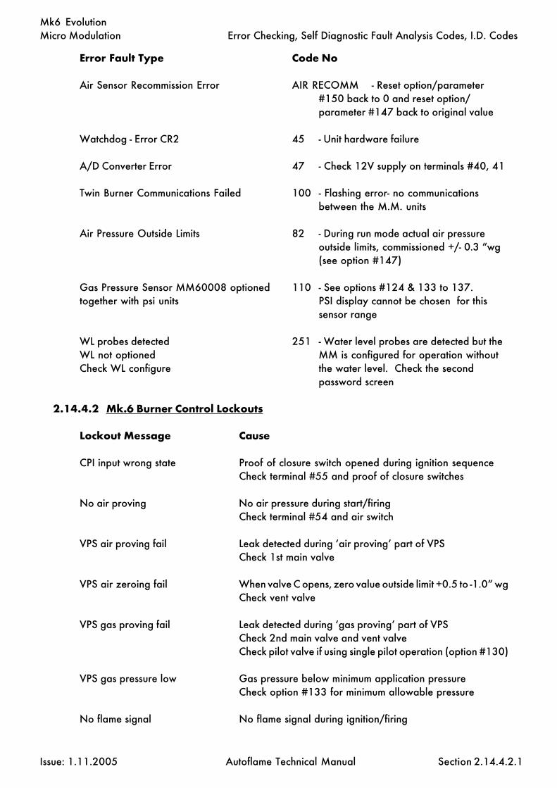
Micro Modulation
Issue: 1.11.2005 Autoflame Technical Manual Section
Mk6 Evolution
2.14.4.2.1
Error Fault Type Code No
Air Sensor Recommission Error AIR RECOMM - Reset option/parameter#150 back to 0 and reset option/parameter #147 back to original value
Watchdog - Error CR2 45 - Unit hardware failure
A/D Converter Error 47 - Check 12V supply on terminals #40, 41
Twin Burner Communications Failed 100 - Flashing error- no communicationsbetween the M.M. units
Air Pressure Outside Limits 82 - During run mode actual air pressureoutside limits, commissioned +/- 0.3 “wg(see option #147)
Gas Pressure Sensor MM60008 optioned 110 - See options #124 & 133 to 137.together with psi units PSI display cannot be chosen for this
sensor range
WL probes detected 251 - Water level probes are detected but theWL not optioned MM is configured for operation withoutCheck WL configure the water level. Check the second
password screen
2.14.4.2 Mk.6 Burner Control Lockouts
Lockout Message Cause
CPI input wrong state Proof of closure switch opened during ignition sequenceCheck terminal #55 and proof of closure switches
No air proving No air pressure during start/firingCheck terminal #54 and air switch
VPS air proving fail Leak detected during ‘air proving’ part of VPSCheck 1st main valve
VPS air zeroing fail When valve C opens, zero value outside limit +0.5 to -1.0” wgCheck vent valve
VPS gas proving fail Leak detected during ‘gas proving’ part of VPSCheck 2nd main valve and vent valveCheck pilot valve if using single pilot operation (option #130)
VPS gas pressure low Gas pressure below minimum application pressureCheck option #133 for minimum allowable pressure
No flame signal No flame signal during ignition/firing
Error Checking, Self Diagnostic Fault Analysis Codes, I.D. Codes

Micro Modulation
Issue: 1.11.2005 Autoflame Technical Manual Section
Mk6 Evolution
2.14.4.2.2
Lockout Message Cause
Simulated flame The flame is present when it should not be. Call for serviceimmediately. This is potentially a dangerous condition.
Fail safe relay fault 57Vent valve output fault 62Main gas output 1 fault 61Main gas output 2 fault 60Start gas output fault 59Motor output fault 58Ignition output fault 63
Shutter fault UV signal detected during shutter operation on UV self checkCheck wiring on terminals #21/22
Prolonged lockout reset Prolonged voltage present on terminal #56/lockout resetbutton permanently pressed
No CPI reset Proof of closure switch not made after valves closed afterfiringCheck terminal #55 and proof of closure switches
Gas pressure low limit Gas pressure low limit exceeded when using a gas sensorCheck option #136
Gas pressure high limit Gas pressure high limit exceeded when using a gas sensorCheck option #137
Gas pressure low Low gas pressure before start up
UV short circuit Connections to UV tube shorted
Oil pressure low limit Oil pressure low limit exceeded when using an oil sensorCheck option #139
Oil pressure high limit Oil pressure high limit exceeded when using an oil sensorCheck option #140
Purge air pressure low Insufficient air pressure during purgeCheck option #141
Option #141 incorrect Option #141 is set without option #148
Watchdog fault 1aWatchdog fault 1bWatchdog fault 1cWatchdog fault 1dWatchdog fault 2aWatchdog fault 2bWatchdog fault 2cWatchdog fault 2d
Error Checking, Self Diagnostic Fault Analysis Codes, I.D. Codes
These terminals are self checked withinthe Mk6. If a voltage is detected whenthe output is off (and vice versa) alockout occurs.
Internal fault diagnostics - contactAutoflame and report code displayed.

Micro Modulation
Issue: 1.11.2005 Autoflame Technical Manual Section
Mk6 Evolution
Ram test failedProm test failedCPU test failedInput faultBC input shortLockout 198Lockout 199Lockout 200Lockout 201Lockout 202
Terminal 86 inverse Terminals #85/86 both have an input or teminals #85/86both do not have an input when using the flame switchoperation- see option #122
Termminal 85-86 fault Electronics fault on either terminal #85 or #86
Prove cct fail Loss of input on terminal #52. Terminal #52 must see aninput at all times from the position to purge to the end of thepost purge
Option 118 incorrect If using the NFPA post purge (option #135 = 2) then option#118 must have a setting of 15 or above.
Gas Sensor Related
Sensor supply voltage 12V supply to sensor outside limits (11.75 - 12.25V)Zero low gas sensor see section 2.14.2.6.2 for zero limitsZero high gas sensor see section 2.14.2.6.2 for zero limitsExcessive VPS Operations VPS has operated 3 times without burner firingSignal dev - gas sensor redundant signals from sensor do not matchCounts low - gas sensor sensor fault - stuck on signal valueCounts high - gas sensor sensor fault - stuck on reference valueSignal high - gas sensor gas pressure exceeds maximum range valueGas sensor (+ number) sensor/Mk6 internal fault - report to Autoflame
Air Sensor Related
Sensor supply voltage 12V supply to sensor outside limits (11.75 - 12.25V)Zero low air sensor lower limit is -1.0”w.g.Zero high air sensor upper limit is +0.5"w.g.Signal dev - air sensor redundant signals from sensor do not matchCounts low - air sensor sensor fault - stuck on signal valueCounts high - air sensor sensor fault - stuck on reference valueSignal high - air sensor air pressure exceeds maximum range valueAir sensor (+ number) sensor/Mk6 internal fault - report to Autoflame
The “Error Checking” software, which is included in every M.M. module, continually interrogates thesystem for component or data handling failure. This intensive self checking programme is inflicted onall peripherals, e.g. positioning motors/load detectors as well as the main M.M. system hardware. Thesafety related areas, both hardware and software, have been examined and accepted for CE & UL.
2.14.4.2.3
Error Checking, Self Diagnostic Fault Analysis Codes, I.D. Codes
Internal fault diagnostics - contactAutoflame and report code displayed.

Micro Modulation
Issue: 1.11.2005 Autoflame Technical Manual Section
Mk6 Evolution
2.14.4.3 TROUBLESHOOTING
Gas/air sensor Diagnostic Codes
Shown at the bottom of the display if parameter #83=1.
Example:
Explanation:
Typical reference signals are 1000±14. If the reference signal values display 0 or are blank then thesensor is wired incorrectly.
Each sensor has two channels. Each channel gives out two values- a pressure signal and a referencesignal. The values displayed are ‘digitised’ signals (range 0-1023). The two pressure signals shouldbe the same. The two reference signals should be the same.
If the two pressure signals are different by more than 10 the averaged value will show 01 and not theaverage of the two signals.
With no pressure applied to the sensor the pressure signal value should be between 20 to 60 (typicallybetween 40 to 50). If the reading goes below 5 then an error will occur due to a negative pressure onthe sensor.
Error Checking, Self Diagnostic Fault Analysis Codes, I.D. Codes
2.14.4.3.1
egarevAlangiS
erusserPlangiS
ecnerefeRlangiS
saGsaG 34 1001 1lennahCrosneS
24 24 0001 2lennahCrosneS
riAriA 05 969 1lennahCrosneS
15 15 079 2lennahCrosneS
saG 34 1001
24 24 0001
riA 05 969
15 15 079
M.M.
1212

Micro Modulation
Issue: 1.11.2005 Autoflame Technical Manual Section
Mk6 Evolution
AC Drive Diagnostic Codes
Shown at bottom right of the display if parameter #83=1.
Example:
Explanation:
1 & 2- should normally be 0.
3 to 5- digitised values, 0-255.
3- represents linearly (0-255) 4-20mA/0-10V the analog output from the MK6.4- represents linearly (0-255) 4-20mA/0-10V the analog commissioned value.5- represents linearly (0-255) 0-20mA/0-10V the analog input into the MK6.
1- window error count value will increment if the difference between 4 & 5 is greater than 10. AnM.M. error will occur if the count reaches 150. This takes approximately 3 seconds.
2- disparity error count value - will increment up if the difference between 4 & 5 is greater than 15. AnM.M. error will occur if the count reaches 50. This takes approximately 1 second.
Error checking is only carried out when the burner is firing.
The correct feedback signals must be attained for purge & ignition to progress, i.e. 5 must be as 4±15.
Error Checking, Self Diagnostic Fault Analysis Codes, I.D. Codes
2.14.4.3.2
1 2 3 4 5
evirDCA5HC 0 0 052 352 452
evirDCA6HC 0 0 001 021 121
0 0 052 352 452
0 0 001 021 121
V.S.D.AIR SENSOR
121212

Micro Modulation
Issue: 1.11.2005 Autoflame Technical Manual Section
Mk6 Evolution
UV Shutter Faults
UV shutter fault– there are two LED’s on the back of the self-check UV. The red LED indicates the presenceof a flame, the yellow LED indicates shutter operation. The red LED will flicker in the presence of UVlight. Every 60 seconds the yellow LED will come on, indicating that the shutter is closing. The red LEDshould then extinguish briefly. If this is not happening check the wiring to self check UV sensor:
Green wire = terminal #22Yellow wire = terminal #21Blue wire = terminal #50Red wire = terminal #51
Error Checking, Self Diagnostic Fault Analysis Codes, I.D. Codes
2.14.4.3.3

Micro Modulation
Issue: 1.11.2005 Autoflame Technical Manual Section
Mk6 Evolution
2.14.5 END USER DAY TO DAY OPERATION
2.14.5.1 Normal Run Operation
Upon initial selection of a commissioned fuel, a logo screen flashes up followed by the 'MM STATUS'screen. The COM led flashes for five seconds.
To adjust the required sepoint press and use the third row accordingly.
To adjust the second/reduced required sepoint press and use the fourth rowbuttons accordingly.
The range of the required setpoint is limited according to the type of sensor being used (see option#1). Note that if a DTI is connected and being used to set the required setpoint it will not be possibleto adjust the required setpoint from the front facia. In the event of the M.M. losing communicationwith the DTI (e.g. DTI powered down) the M.M. will run stand alone after approximately 30 seconds.When the M.M. is running stand alone the required setpoint can be set locally on the front facia (anyprevious DTI disable command will also be ineffective). It is possible to lock the required/reducedsetpoints without using a DTI so that this cannot be changed through the front facia (see section2.14.20).
If the burner control circuit is closed the burner system will sequence through the burner start upprocedure. The system purges and ignites, and twenty seconds (nominal) after ignition the systemmodulates.
Values are displayed according to the selected screen. There are a number of possible screens asshown on the next page. To select one of the display modes just press:
The respective LED will remain illuminated to indicate which mode is selected. The COM and E.G.A.modes are only selectable if an E.G.A. is optioned on the system.
In the event of the system being powered down the commissioning data, options, parameters andrequired setpoint are all memorised. During normal run operation the RUN led is on all the time.When no fuels are selected only the RUN LED remains illuminated.
If an E.G.A. is operative on the system it will calibrate every time the burner starts and stops. WhenCOM or EGA display modes are selected ‘EGA CALIBRATING’ is displayed when the E.G.A. iscalibrating. If the E.G.A. is cooling, COOL is displayed. If the burner is not firing, EGA is displayed.When the burner is firing both modes show E.G.A. if the actual value has not reached the value atwhich trimming is permitted. (see option #28). If an E.G.A. error has occurred the error code numberis displayed if either EGA or COM modes are selected.
The software version number can be displayed by by pressing the Top CH1 b u t t o n ssimultaneously, when in the M.M. display mode.
End User Day to Day Operation
COM
E.G.A
123123
M.M.
1212
DISPLAYSTATUS
123123
2.14.5.1.1
FLAMESCANNER
LOCKOUTRESET
IBSSEQUENCING
123123
FUELMETERING
123123 OUTSIDE
TEMPCOMPENSATION
123123
This button also scrolls to the Valve Proving Screen
DISPLAYSTATUS
121212
DISPLAYSTATUS
123123123
V.S.D.AIR SENSOR
1212

Micro Modulation
Issue: 1.11.2005 Autoflame Technical Manual Section
Mk6 Evolution
Variable Speed DriveThere are two control channels availablefor driving inverters. These can be 0-10volts or 4-20 mA as required. This screenshows graphically the input & output sig-nals to the variable speed drives.The actual wind box pressure is shownagainst the commissioned data.
E.G.A. On Line ValuesWhen an Exhaust Gas Analyser (E.G.A.)is included in the system,this screen showsthe actual values of the gases beingmeasured in the flue plus the exhaust gastemperature, ambient temperature, dT,and efficiency. A further screen showsthe commissioned values.
Outside TemperatureCompensationThis screen is a graphic display show-ing the currently pre set relationshipbetween boiler temperature set pointand outside ambient temperature.This relationship can be changed bythe operator over a wide tempera-ture range.
M.M. StatusShows the actual positions of air andfuel valves as well as fan speed infor-mation from inverters, which is expressedas a 4-20mA or 0-10V signal.
IBS StatusFor a multi boiler installation, thisscreen shows which is the lead boilerplus information on temperature andpressure set points.
Lockout History.This screen gives a real time log of thelast 16 lockouts. Details include time,date, a brief discription and reset time.
System StatusThis screen shows the present firingrate, which fuel is being used, therequired setpoint, reduced setpointand the actual temperature/pressure.
Fuel Metering StatusThis screen displays which fuel is cur-rently selected, the consumption atthis point in time and the total fuelused to date.
Several different displays are available to provide the operator with unambiguous information throughstart-up and normal operation.Selectable screens provide the following information:
Flame Scanner Signal.Post Purge.Pre Purge.Air Damper position.Main fuel valve.Pilot/start gas valve.Ignition.Operation of fan.
Valve ProvingThis screen displays the positions offuel valves, open or closed duringpressure proving prior to burner firing.During run the on-line and commis-sioned gas pressures are displayedwith +/- limits.
Flame Scanner Status, Screen Menu
2.14.5.1.2
End User Day to Day Operation

Micro Modulation
Issue: 1.11.2005 Autoflame Technical Manual Section
Mk6 Evolution
2.14.5.2.1
2.14.5.2 Adjusting Clock Settings, Contrast and Actual Load Reading
Setting Time & Date
To adjust the time and date settings go into COM mode (power down the unit and restart. The
light will be flashing and you have 5 seconds to press it).
'ENTER PASSWORD' screen is displayed. Set password to: . Press .
'Set Clock' screen is displayed:
To adjust the values use the corresponding buttons.
When finished press the flashing button to submit to memory.
Adjusting the Screen Contrast
Hold down any of the screen select buttons:
and then use the top row to adjust the contrast accordingly.
Calibrating Actual Load Reading
A facility exists to adjust small errors in the actual pressure or temperature displayed on the status screen.
To increase the value press and the CH3 simultaneously.
To decrease press and the CH3 .
COM
1010
ENTER
MEMORY
CLOSE
DISPLAYSTATUS
123123123
M.M.
123123123
E.G.A
123123123OUTSIDE
TEMPCOMPENSATION
123123123 FUEL
METERING
121212 IBS
SEQUENCING
121212 FLAME
SCANNERLOCKOUT
RESET
RUN
RUN
End User Day to Day Operation
SET CLOCK
DAY MONDAYDATE 17MONTH NOVEMBERYEAR 97HOURS 12MINUTES 30 24 hour clock
V.S.D.AIR SENSOR
123123123

Micro Modulation
Issue: 1.11.2005 Autoflame Technical Manual Section
Mk6 Evolution
2.14.5.3 EPROM Version Numbers
To display the software version number select the M.M. display screen, then press the channel 1 up and
down buttons simultaneously.
Software version numbers are also displayed on the password screen when in commissioning mode.
2.14.5.3.1
EPROMVERSION NUMBERS
BC 5.03 MM 6.20 DI 6.20

Micro Modulation
Issue: 1.11.2005 Autoflame Technical Manual Section
Mk6 Evolution
2.14.6.1
Electrical Schematics
PRE-
IGN
ITIO
N
SAFE
TY IN
TERL
OC
K C
IRC
UIT
RUN
NIN
G IN
TERL
OC
K
POSITIONING MOTORS
*NOTE:FOR 110v, TERMINAL 69 FEEDS POSITIONING MOTORS VIAA 110-24v TRANSFORMER AS SHOWN IN DOTTEDLINES.
6A FUSED SUPPLY
110Vac
LINE VOLTAGE
72
SELF
CH
ECK
U.V
DET
ECTO
R
CA
LL F
OR
HEA
T
BURN
ER O
N/O
FF
AIR
PRO
VIN
G S
WIT
CH
GA
S V
ALV
ES C
.P.I.
/PO
C
LOC
KO
UT
RESE
T
STA
RT/P
ILO
T FU
EL V
ALV
E
MA
IN F
UEL
VA
LVE
1
MA
IN F
UEL
VA
LVE
2
IGN
ITIO
N T
RAN
SFO
RMER
DET
ECTO
R
DEL
AY
TO P
URG
EEX
TERN
AL
AU
XILI
ARY
GREEN
YELLOW
22
21
N GA
S BO
OST
ER
(OPT
ION
AL)
PRES
S.O
UTL
ETPR
ESS.
INLE
T
LIV
E/H
OT
NEU
TRA
L
EART
H
BURN
ER M
OTO
R
58
BLU
E
UV
5150 5150
RED
LIM
IT S
TAT
5150 S 555352 54 56 57
NO
T U
SED
VEN
T V
ALV
E
CC
WL
CH
1C
W
6059 61 6362 64 6766 68 7069 71
(CO
MM
ON
SYS
TEM
ALA
RM)
FLA
ME
SWIT
CH
AT
NO
FLA
ME
STA
TE.
SEC
ON
D S
ET P
OIN
T SE
LEC
T
LEA
D B
OIL
ER S
ELEC
T (IB
S)/L
OC
AL-R
EMO
TE P
ID
L/O
, MM
& E
GA
ALA
RM O
UTP
UT
I.B.S
. 2-P
ORT
VA
LVE
24Vac
STA
ND
BY W
ARM
ING
NIG
HT
SET
BAC
K/
CC
W
CC
W
CC
W
L L
CH
2
CH
3
LC
H4
CW
CW
CW
LN
NO
T U
SED
LN
787573 74 76 77 8079 81 8382 84
FUEL
2
FUEL
1
LIN
E V
0 V
FUEL
4
FUEL
3
HA
ND
AU
TOL.F.
H.
908785 86 88 89 9291 93 9594
SERI
AL
PORT
AU
X. R
S485
BOIL
ER W
ATE
RTE
MP.
SEN
SOR
BOIL
ER S
TEA
MPR
ESSU
RE
GA
S PR
ESSU
RE
AIR
PRE
SSU
RE
DTI
/IBS
RS4
85SE
RIA
L PO
RT
E.G
.A. A
NA
LYSE
RRS
485
Mk.
6
TWIN
BU
RNER
OU
TSID
E TE
MP.
0-10
V/4
-20m
A
AU
X A
NA
LOG
UE
CH
6 O
UTP
UT
0-10
V/4
-20m
A
0-10
V/4
-20m
A
CH
5 O
UTP
UT
0-10
V/0
-20m
A
AU
X A
NA
LOG
UE
CH
6 IN
PUT
FRO
M V
SD0-
10V
/4-2
0mA
0-10
V/4
-20m
AFR
OM
VSD
CH
5 IN
PUT
MM60001/E WITH OR WITHOUT WATER LEVEL P.C.B. 120/230Vac
LOW VOLTAGE
TO V
SD
11421 S3 65 7S 98 10
I-/O
V+VI+ I+
I-/O
V+V
I-/O
V+V
+VI+ I+
INPU
T
GRE
EN
YELL
OW
14S12 13 S15 1716 20S18
BLU
E
RED
19 2221S
I-/O
V
I-/O
V
I-/O
V+V
+VI+
TO V
SD
OU
TPU
T
I+
SEN
SOR
SEN
SOR
36
YELL
OW
YELL
OW
29262423 25S 2827 S
GRE
EN
3230 31S 34
RED
BLU
E
33
GRE
EN
35
23 24 23 31 27 28
RS48
5
SEN
SOR
RED
BLU
E
41
GRE
EN
38S 37S S39 40 4342 4544 4746 S
WH
ITE
RED
SEN
SOR
CO
NTR
OLL
ERLO
AD
/MO
DU
LATI
ON
EXTE
RNA
L
RATE
FIRI
NG
%
CH
2A
IRC
H1
FUEL W
0V+V
0V
W0V
+V0V
POSITIONING MOTORPOTENTIOMETERS
W+V
W+V
CH
4C
H3
3 2 1
OIL
PRE
SSU
RESE
NSO
R
NO
N-R
ECYC
LIN
G IN
TERL
OC
K
OR
(SEE
PA
RAM
ETER
92)
HIG
H IN
TERL
OC
K, D
ELA
Y PU
RGE
TIM
E

Micro Modulation
Issue: 1.11.2005 Autoflame Technical Manual Section
Mk6 Evolution
2.14.6.3
Electrical Schematics
Pressure Sensor Part no. Actual Range Proof Pressure0-18 Bar MM10008 0 - 23.0 bar (30 - 330 P.S.I.) 450 psi0-30 Bar MM10009 0 - 38.0 bar (30 - 550 P.S.I.) 750 psi0-3.0 Bar MM10010 0 - 3.80 bar (3.0 - 55.0 P.S.I.) 200 psi
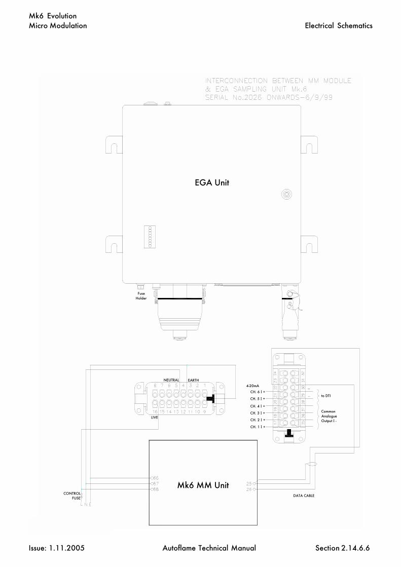
Micro Modulation
Issue: 1.11.2005 Autoflame Technical Manual Section
Mk6 Evolution
2.14.6.6
Electrical Schematics
EGA Unit
Mk6 MM UnitDATA CABLE
NEUTRAL EARTH
LIVE
CONTROL FUSE
to DTICH. 6 I +
CH. 5 I +
CH. 4 I +
CH. 3 I +
CH. 2 I +
CH. 1 I +
4-20mA
Common Analogue Output I -
Fuse Holder

Micro Modulation
Issue: 1.11.2005 Autoflame Technical Manual Section
Mk6 Evolution
2.14.6.10
Electrical Schematics

Micro Modulation
Issue: 1.11.2005 Autoflame Technical Manual Section
Mk6 Evolution
2.14.6.11
Electrical Schematics

Micro Modulation
Issue: 1.11.2005 Autoflame Technical Manual Section
Mk6 Evolution
2.14.7 TWIN BURNER OPERATION
2.14.7.1 Twin Burner Commissioning
Options #14 and #33 have to be set to correctly implement twin burner operation. Refer to the optionsection. For commissioning purposes it is easiest to set option #14 on each M.M. to value 0, andcommission each burner individually. It is the commissioning engineer’s responsibility to ensure thatno adverse effects are caused as a result of this. Particularly, stress to a boiler not designed to have onlyone burner firing. If this is the case then both burners can be commissioned simultaneously. AFTERCOMMISSIONING SET OPTION #14 TO IT'S TWIN BURNER VALUE ON BOTH M.M.s
Before commencing commissioning set the following options (refer to options section for more details):
Option #33:
Set value of left hand burner to its appropriate identification number, e.g. #1. Set the right hand burnerto the Identification of the left hand burner +1, i.e. #2.
Option #33 will have to be interpreted if the boilers are numbered right to left. The details here are forleft to right numbering.
Other options may be set as usual.
Normal Operation
Only the odd numbered M.M. needs an input on terminal #88 to make this boiler lead boiler. If aconnection is made to the even number M.M. it will be ignored. The same applies for the hand/auto/low flame hold inputs #94/95, i.e. they do not need any connection on the even number M.M. if option#14 = 1. If option #14 = 2 then terminals #94/95 should be wired as normal for hand operation.
The even number burner always takes its load index from the odd number burner including when in‘Hand’ mode. If communications between the two burners fail, each M.M. will open its internal stat andapproximately every three seconds the displays on each M.M. show a flashing ERROR 100 to indicatea communications failure if option #14 = 1. If option #14 = 2 then the 2 M.M.s run stand-alone.
When entering the flow metering for sequencing purposes it is necessary to put both M.M.s into the“Flow Metering” mode at the same time,
i.e. Start up both burners, wait until both are modulating then press and on oneof the M.M. units.
Within 10 seconds press a n d on the other M.M.
Keep the firing rate of each burner similar when entering profile, i.e. do ‘point 1’ on each M.M. then‘point 2’ on each M.M, e.t.c. This is important as the boiler may be susceptible to stress if one tube isfired at a different rate to the other. The required setpoint and actual value on the even numbered M.M.will mimic the values on the odd number M.M.
Twin Burner Operation
2.14.7.1.1
M.M.
123123 COM
M.M.
1212COM

Micro Modulation
Issue: 1.11.2005 Autoflame Technical Manual Section
Mk6 Evolution
The internal stat of the even numbered M.M. follows the odd number M.M.
If Option #14 = 1 then the internal stat of both M.M.s will open if there is a period of more than 10seconds when one M.M. is modulating and the other is not.
One M.M. unit will remain at the low fire position until the other unit is at the low fire position beforeoutputting the low position interlock to the burner control box.
The load detector input in the even numbered M.M. can be left open circuit, it will not be error checked.
If an error condition arises on one or other of the M.M. units and option #14 = 1 then the other unitwill open its internal stat and flash ERROR 100.
2.14.7.1.2
Twin Burner Operation

Micro Modulation
Issue: 1.11.2005 Autoflame Technical Manual Section
Mk6 Evolution
2.14.7.3
Twin Burner Operation
The same arrangement applies to the Mini Mk6.

Micro Modulation
Issue: 1.11.2005 Autoflame Technical Manual Section
Mk6 Evolution
Low Flame Hold and Hand Operation
‘Low Flame Hold’ and ‘Hand’ operation are only effective when the burner is firing. They have no effectwhen the burner is off or during the burner start up cycle. They are effected by applying a mains voltagesignal to terminal #95 for low flame hold, or terminal #94 for hand operation. When these inputs haveno mains signals applied, the system modulates according to the PID control.
Low flame hold is brought into operation if terminal #94 has a signal applied when the ignition partof the burner start up cycle takes place. The minimum flame position will be maintained from now on,until the input from terminal #94 is removed. Low flame hold will be established again by applying aninput to terminal #94 again. During low flame hold the PID control is ignored.
‘Hand’ operation enables the fuel valve position to be set to a specific position, in the range of minimumto maximum flame. Once a position has been set it is recorded in the M.M. units memory. Each timethe burner starts the fuel valve will be positioned to the ‘hand’ position set previously, even if the M.M.unit has been powered down. The M.M. system sets the fuel valve to the hand position whenever thereis a mains signal on terminal #95. Once the burner is firing the ‘hand’ position can be adjusted by
switching to the M.M. screen and using the bottom row of buttons on the Mk6 facia.
See option #60 for details on bumpless transfer.
If hand and low flame hold operations are selected at the same time, via inputs both on terminals#94 and on #95, then low flame hold takes priority.
2.14.8 HAND/AUTO AND LOW FLAME HOLD FACILITIES
Hand/Auto & Low Flame Hold Facilities
2.14.8

Micro Modulation
Issue: 1.11.2005 Autoflame Technical Manual Section
Mk6 Evolution
2 .14.9 FAULT FINDING
WARNING ! ! ! !MAINS AND HIGHER VOLTAGES EXIST ON THE M.M. AND POSITIONING MOTORS.THE SYSTEM CONTROLS A COMBUSTION PROCESS.
Only competent personnel aware of the implications of the above warning should attempt fault finding.Personnel must be responsible for the conditions under which fault finding takes place. (e.g. isolationof fuel supply)
Note: Personnel not familiar with the system should carry out tests in the order written.
The method of fault finding described is for a system that has been working correctly and has gonewrong. It is not for trouble shooting new systems which may for example have incorrect wiring. It alsowill not turn up faults which are a result of tampering.
Before commencing any fault finding:-
Set option #12 to 0.Set option #9 to value 0 (NOTE - only limit stat effective) or ensure that the actual value is
sufficiently less than the required setpoint in order to allow the system to start up and run for a prolongedperiod.
The internal stat must be made in order for the stat circuit to be complete.
PRELIMINARY CHECK
If display is blank check for RUN led, if RUN led is also blank check mains supply to unit. Remove backcover of M.M. and check mains supply on terminals #66/67/68. If supply to unit is good, removesupply to unit and check fuse.
If unit is still blank it is likely there is a fault on the M.M.
Ensure there is no lockout condition.
Deselect fuelSelect fuel
Press before COM l.e.d. stops flashing (5 seconds).
Check stat circuit is made.
Refer to section 2.14.3.1 for the burner start up sequence and timings. Follow these through to find apossible fault.
Fault Finding
2.14.9
COM

Micro Modulation
Issue: 1.11.2005 Autoflame Technical Manual Section
Mk6 Evolution
2.14.10.1
2.14.10 OTHER INFORMATION AND ILLUSTRATIONS
2.14.10.1 Mk6 Evolution M.M. Front Facia Details
Other Information and Illustrations

Micro Modulation
Issue: 1.11.2005 Autoflame Technical Manual Section
Mk6 Evolution
Bottom View shown with lid in position.
2.14.10.2
Other Information and Illustrations
2.14.10.2 Mk.6 M.M. Fixing Holes & Dimensional Details

Micro Modulation
Issue: 1.11.2005 Autoflame Technical Manual Section
Mk6 Evolution
2.14.10.3
Other Information and Illustrations
2.14.10.3 Schematic View Of IR Upload Download
Software installation:
Insert CD and follow the installation procedure (setup.exe).
When SETUP has completed, insert the key diskette into drive A: click on start and choose run. TypeA:\INSTALL.bat and press enter.
The software needs to be configured to the serial (COM) port that the IR lead is connected to. Thishappens the first time the Mk6 Upload/Download software is run.
WARNING
IT IS THE RESPONSIBILITY OF THE OPERATOR TO ENSURETHAT AFTER AN UPLOAD ALL THE OPTIONS, PARAMETERSAND FUEL/AIR RATIO COMMISSION DATA ARE CHECKEDFOR CORRECTNESS.

Micro Modulation
Issue: 1.11.2005 Autoflame Technical Manual Section
Mk6 Evolution
2.14.10.4 Maintenance and Servicing
The Micro Modulation unit uses solid state technology. It requires no routine maintenance. If itdevelops a fault that it can diagnose and display it will do so.
The positioning motors/gas/oil valves also do not require routine maintenance. Any fault associatedwith these parts is usually diagnosed by the M.M.
2.14.10.5 Installation Precautions
The reliability of the equipment may be impaired if used in environments where strong electromagneticfields exist. If for example the equipment is installed in a boiler house at the top of a high rise buildingwhere radio systems exist then additional EMC (Electro Magnetic Compatability) measures may haveto be considered
2.14.10.4
Other Information and Illustrations

Micro Modulation
Issue: 1.11.2005 Autoflame Technical Manual Section
Mk6 Evolution
1. Go to options, set option #57 to 1 (default 0).
2. When the above is displayed press , this will initiate the flow metering setup mode.
3. Next time the burner starts the M.M. will go into the ten point setup mode for flow meteringautomatically.
4. In this mode the display will show fuel valve position in degrees angular and the flow units
which can be adjusted by using the CH1/CH2/CH3/CH4/CH5 buttons as shown at
the bottom of the screen.
Note:
a) The CH4 window confirms to the commissioning engineer which of the 10 points arecurrently being measured.
b) The minimum numerical value for fuel flow that can be entered into memory is 0.01.The maximum numerical value for fuel flow that can be entered into memory is 999.0
c) The values are entered in descending order, i.e. point #1 is maximum flame andpoint #10 is at minimum flame. The 10 sequential point on the load index are alllocated automatically by the M.M. All values are in units/minute.
5. When fuel flow has been calculated or read off of a commissioning fuel flow meter the valueis entered as detailed in point #4.
T h e button is then pressed and the value is logged in the M.M. memory.
6. The above detailed data entry routine is repeated until all 10 points have flow valuesallocated to them.
7. When the last (10th) point has been entered the burner continues to fire.
8. To display Fuel Flow Metering press button.
9. To reset the totalising value to 0 (zero) for the individual fuel selected set option #57 to 2,
press at that time. To reset all totalised values for each fuel use parameter #64.
Note: Fuel flow metering measurement now automatically starts totalling the amount of fuel usedfrom the moment the main gas valves are energised. Previously this was counted from the ignitionoutput and a delay time then had to be set via option #58. This option no longer applies with theMk6 Evolution.
2.14.11 FUEL FLOW MEASUREMENT AND METERING OPERATION
Fuel Flow Measurement & Metering
2.14.11
ENTER
MEMORY
ENTER
MEMORY
FUELMETERING
1212
ENTER
MEMORY
Micro Modulation
Issue: 1.11.2005 Autoflame Technical Manual Section
Mk6 EvolutionGolden Start
2.14.12 GOLDEN START
This facility enables an ideal ignition/start position to be set into memory that is not necessarily lowflame or indeed part of the standard modulating load index.
To enable this facility to go to option #29, set to 0 (default value = 1) and press
To disable this facility go to option #29, set to 1 and press
To implement the above the system/burner is commissioned in the normal way, i.e. press
Enter the password, enter the close position, enter the open position, enter the start (light-off)position (adjust fuel/air positioning motors to give initial arbitrary ignition position). This position isnot memorised. The burner will fire and the start position LED will flash again.
Press , LED will remain stable, adjust the fuel/air positioning motors to give the ideal
ignition/start up position.
P res s and proceed with the commissioning routine in the normal way.
Notes:
1. The golden start/ignition position of the fuel and air positioning motors is completelyindependent from the modulating load index commissioned value data.
2. The facility is particularly useful on combustion systems with large turndowns and when firingheavy fuel oil, as it enables the burners to start/ignite at a fuel rich position and then, after astable flame is established, to revert to the commissioned values for fuel/air ratio.
3. WARNING- this facility is common to all fuels (F1, F2, F3 & F4). A value must be entered oneach programmed fuel. Note: As of June 2005, the golden start only needs to be entered forthe required fuel.
4. The time that the M.M. holds the golden start position for is adjustable, see parameter #15.(default value is 5 seconds, range 0-255 seconds). This timer starts from the ignition point. Afterthis time the air damper will open and the fuel valve will remain at the same position until thefuel/air ratio is on the original commissioning curve. At this point the M.M. will start to modulatebased upon the load demand and the PID control.
5. If the commissioning engineer wishes to change the golden start position retrospectively thiscan be re-entered, without fully recommissioning the burner, in the following manner:
Go into the commission mode, enter the password, enter the close and the open positions andenter, as previously described, to the point where high flashes then deselect fuel or power down.In this way the new golden start position is entered.
6. It is important to appreciate that the golden start position is completely independent of the fuel/air paired values that are entered for the normal modulating load index/range.
2.14.12
ENTER
MEMORY
ENTER
MEMORY
COM
START
ENTER
MEMORY

Micro Modulation
Issue: 1.11.2005 Autoflame Technical Manual Section
Mk6 Evolution
2.14.13 ONE POINT CHANGE
To change a point:-
Start up the burner in the normal way.
Once modulating press and simultaneously. 'ENTER PASSWORD' should
be displayed. Set the password and press in the same way as if going into normal
commissioning, the channel position values should be displayed. The valves track to the nearestcommission point (e.g. HIGH/INTER/START).
When all the values have settled at their appropriate positions ENTER flashes. If this point is to be
changed press . If not press the CH1 button to move to the next point up or
the CH1 button to go to the next point down. The M.M. detects which point has been
selected and will steady the appropriate LED on either HIGH, INTER or START as during normal
commissioning. Once the correct point to be changed is displayed press . It should now
be possible to adjust the fuel/air ratio by using the CH1 - CH6 buttons. Adjust the values
as desired and when the correct values are set press . If an E.G.A. is optioned the
button will flash, press to view. If the E.G.A. is optioned for AUTOTRIM then this will be carried outand E.G.A. values stored.
Once complete the M.M. will revert to just ENTER and RUN flashing. If desired another point can be
selected and changed. Otherwise press and the M.M. reverts to normal modulation.
If the CH1 (fuel) HIGH or START position has been adjusted check the flow metering. It is likely thatthe 10 point flow calibration must be carried out again.
2.14.13
One Point Change
START COM
CLOSE
ENTER
MEMORY
E.G.A
1212
ENTER
MEMORY
ENTER
MEMORY
RUN
Micro Modulation
Issue: 1.11.2005 Autoflame Technical Manual Section
Mk6 Evolution
2.14.14 FLUE GAS RECIRCULATION
Flue Gas Recirculation (FGR) is a method whereby a quantity (approximately 15%) of the boilerflue gases are fed back to the burner and mixed with the combustion air. The virtue of FGR is thereduction of NOx gases. With the FGR facility, positioning motor channels 3 or 4 can be used tocontrol the amount of flue gas fed back. It is not good practice to feed back the gases when the fluegas is cold, so all the elements (i.e. positioning motors and VFD’s) can be set at ‘FGR’ positionsuntil the gases are hot. During this time the elements (CH3 or CH4) controlling the FGR wouldnormally be set closed. Once the gases are hot, modulation takes place in the normal way usingthe curve entered during commissioning.
To ascertain if the gases are hot a number of options have been added:
Option #48A time in seconds that the FGR positions are held for. This timer starts from the point of
release to modulation. If a golden start is used in conjunction with the FGR start then the FGRstart timer will begin at the end of the golden start timer.
Option #49An offset amount (e.g. 20) below the required setpoint (e.g. 100). This gives a threshold
value of 80 (100 – 20). The FGR positions are held until the actual value has attained thethreshold value (80). Once this actual value is reached then normal modulation will occur.
Option #50This is an enable/disable type option. If enabled an E.G.A. must be present on the system.
The FGR positions are held until the exhaust temperature value from the E.G.A. reaches 248F(120C). Once the exhaust gases reach this temperature then normal modulation will occur.
It is possible to use all three of the above options in order to keep the FGR start positions. If thisis done then the timer will be held firstly and then the other two options must be satisfied forrelease to modulation.
It is important to check the setting of parameter #90, which determines at what time the FGR startposition will be entered.
If the burner has been commissioned and it is necessary to add an FGR start position, set parameter#90 to 1, and one of the above options to enable FGR start. Then enter the commissioning modeand after the start position is entered the M.M. will prompt for the FGR start position to be entered.After this is entered the M.M. can be reset and this FGR start position will be stored in the memory.
2.14.14
Flue Gas Recirculation

Micro Modulation
Issue: 1.11.2005 Autoflame Technical Manual Section
Mk6 Evolution
2.14.15 PILOT TURN DOWN/CHECK SWITCH FACILITY
When the system is in commissioning mode only, a facility has been provided that enables acommissioning engineer to pause the ignition sequence of the burner. If the lockout button is pressedduring the first safety time the burner control will ‘pause’ at this position. This enables the commission-ing engineer to make adjustments to the start gas flame. If the flame goes out during this time a lockoutis set after 15 seconds. If the flame is present and the ‘pause’ condition is left indefinitely a lockoutwill be set after 10 minutes. If the lockout button is pressed again the ignition sequence continues.While paused the lockout LED on the front fascia flashes. The ‘pause’ facility can also be activatedduring the pilot prove and main flame prove phases. When the system is in a run mode the facility isdisabled.
WARNING
IT IS THE RESPONSIBILITY OF THE OPERATOR TO ENSURE THATUSE OF THE PAUSE FACILITY DOES NOT LEAD TO A HAZADOUSSITUATION.
2.14.15
Pause Facility

Micro Modulation
Issue: 1.11.2005 Autoflame Technical Manual Section
Mk6 Evolution
2.14.16 TIME CLOCK FACILITY
Time Clock Set Up
To adjust the time clock settings go into commissionning mode (power down/reselect fuel, press COMwithin 5 seconds). The 'ENTER PASSWORD' screen should now be displayed. It is also possible tochange the time clock settings online- see section 2.14.20.
Set the password to and press CLOSE.
The 'Time Clock' screen will be displayed:
Note: items marked * not displayed during setup
Use the channel 6 up/down buttons to select the day and item to be adjusted. The selected item willflash.
For start/stop times:Set the hour by means of the channel 1 up/down buttons.Set the minute by means of the channel 2 up/down buttons.
For Mode:Select the desired operation by means of the channel 1 up/down button.
To enable/disable the time clock operation use the channel 5 up/down buttons.
Press ENTER to memorise the time clock configuration. If enabled, the time clock operates from nowon when in run mode. To disable time clock operation, enter the password as described above and setthe time clock to disabled using the channel 5 up/down buttons and press ENTER.
Time Clock Operation
Operation during and outside the start/stop times is according to the mode selected:ON off The burner runs and modulates according to the normal required setpoint during thestart/stop times. Outside of the start/stop times the burner is held off.ON rsp The burner runs and modulates according to the normal required setpoint during thestart/stop times. Outside of the start/stop times the burner runs and modulates according to the reducedsetpoint.
The normal setpoint and reduced setpoint are adjustable by means of the channel 3 and channel 4 up/down buttons respectively when the DISPLAY STATUS screen is selected.
In normal run operation the Time Clock screen is selected on the third press of the status button.2.14.16
Time Clock Facility
1111

Micro Modulation
Issue: 1.11.2005 Autoflame Technical Manual Section
Mk6 Evolution
2.14.18.1 AUTOMATIC COMMISSION OF AIR PRESSURE VALUES
A facility has been added to the Mk6 Evolution so that the air pressure values (during VPS and for eachfuel/air ratio point entered) can be commissioned without having to carry out a full fuel air ratiocommission.
To invoke this facility the system must already be commissioned on fuel /air ratio. Option/parameter150 must be set to value 7 then the enter button pressed. Options/parameters 147 must be noted andset to 0-off so that air pressure limit errors do not occur while the system is running.
Start up the system as normal. Once the burner is firing the system attains the high fire positions andsamples and stores the air pressure at that point. The first fuel/air ratio inter positions are then attainedand the air pressure again sampled and stored. This process is repeated until all fuel/air ratio inter andstart positions are complete. The new air pressure values are then permanently stored and thereafter anMM ERROR is set - AIR RECOMMSSION. (This is to bring to the attention of the operator that Options/Parameters must be adjusted back to operational settings). The error must be cleared and option/parameter 150 set back to 0. If not set back to 0 the air values will be commissioned again and the M.M.ERROR will ensue. Options/parameters 147 must also be adjusted to their appropriate values.
2.14.18.2 AUTOMATIC COMMISSION OF GAS PRESSURE VALUES
A facility has been added to the Mk6 Evolution so that the gas pressure values (during VPS and for eachfuel/air ratio point entered) can be commissioned without having to carry out a full fuel air ratiocommission.
To invoke this facility the system must already be commissioned on fuel /air ratio. Option/parameter150 must be set to value 8 then the enter button pressed. Options/parameters 136/137 must be notedand set to 0-off so that gas pressure limit errors do not occur while the system is running.
Start up the system as normal. Once the burner is firing the system attains the high fire positions andsamples and stores the gas pressure at that point. The first fuel/air ratio inter positions are then attainedand the gas pressure again sampled and stored. This process is repeated until all fuel/air ratio inter andstart positions are complete. The new gas pressure values are then permanently stored and thereafteran MM ERROR is set - GAS RECOMMSSION. (This is to bring to the attention of the operator thatOptions/Parameters must be adjusted back to operational settings). The error must be cleared andoption/parameter 150 set back to 0. If not set back to 0 the gas values will be commissioned again andthe MM ERROR will ensue. Options/parameters 136/137 must also be adjusted to their appropriatevalues.
THE OPERATOR MUST NOW CHECK THE SYSTEM FORCORRECT OPERATION.
Check the gas pressure commission value displayed during VPS operation. Once the burner is firing,check the gas pressure commission values for each fuel/air ratio point entered - this can be achievedby means of the hand operation facility.
Automatic Commission Of Gas Pressure Values
2.14.18
Micro Modulation
Issue: 1.11.2005 Autoflame Technical Manual Section
Mk6 Evolution
2.14.19 FLAME DETECTION USING EXTERNAL FLAME SWITCH
To configure operation with a flame switch option/parameter #122 must be set to 1.
The operation of terminals #85 and #86 must be as follows:
When the flame switch is indicating no flame, the voltage on terminal #85 must be 0Vac.
When the flame switch is indicating the presence of a flame, the voltage on terminal #85 must bemains voltage (110/230Vac).
Terminal #85 is the functional input for detecting the flame.
Terminal #86 is solely for the purpose of checking that terminal 85 is operating correctly. Terminal#86 must seen to be the inverse of terminal 85.
If terminal #85 is at 0Vac, terminal #86 must be at mains voltage.
If terminal #85 is at mains voltage, terminal #86 must be at 0Vac.
If terminal #86 does not follow the inverse of terminal #85 the following lockout will occur -terminal #86 inverse.
Flame Switch Configuration
Within the M.M. there is a latency of 250 milliseconds on the monitoring of terminal #85. Toensure a 1 second overall flame failure response time, it is essential that the response time of theflame switch is set to no more than 750 milliseconds.
Flame switches often provide a volt free change over contact to indicate the flame status.Alternatively, they may provide a pair of `inverse’ outputs. If the flame switch only provides asingle output terminal, a relay will have to be installed between the flame switch and the M.M. toprovide a set of volt free changeover contacts.
Flame Detection Using External Flame Switch
2.14.19

Micro Modulation
Issue: 1.11.2005 Autoflame Technical Manual Section
Mk6 Evolution
2.14.20 ON-LINE CHANGES
A facility exist in the Mk6 M.M. Evolution that allows certain changes to be made whilst the burneris firing- ‘on-line changes’. The various changes that can be made are listed below:
1. Lock the required setpoint and reduced setpoint.2. Change options.3. Change parameters.4. Change the time-clock facility settings.5. Change the channel labels.
To make on-line changes
1. It is important to firstly be in the screen.
2. Press and hold for 5 seconds. If this button is not held for 5 seconds then step 1
and 2 must be repeated. Once this is entered correctly a screen prompting a password will appear.
3. Use the CH1 and CH2 buttons to enter the password and then press . If
the password is entered incorrectly then the system will not allow the user to proceed.
4. Once the password is entered correctly the ‘SELECT FUNCTION’ screen will appear. Using
the CH1 buttons it is possible to scroll through the various items that can be changed.
When the desired selection is displayed press to select it.
Note: can be pressed at any time in order to return to normal operation.
The current selected function will only be updated if the button is pressed.
Lock-Unlock Required Setpoint and Reduced Setpoint
I f is pressed when ‘LOCK REQUIRED VALUE’ is displayed it is possible to lock or unlock
the required and reduced setpoints. Use the CH1 button to lock the setpoints. Use the CH1
button to unlock the setpoints. Press to permanently save the setting. The ‘SELECT
FUNCTION’ screen will now be displayed again. It is now possible to press to return to
normal operation, or make further changes on-line.
On-line Changes
2.14.20.1
DISPLAYSTATUS
123123
M.M.
1212
ENTER
MEMORY
CLOSE
ENTER
MEMORY
ENTER
MEMORY
ENTER
MEMORY
RUN
RUN

Micro Modulation
Issue: 1.11.2005 Autoflame Technical Manual Section
Mk6 Evolution
Options
I f is pressed when ‘OPTIONS’ is displayed then the ‘SET OPTIONS’ screen will be
displayed and options are able to be changed on-line (whilst in run-mode, burner on/off). Refer to
section 2.14.2.4 for instructions on changing options. Press to permanently save the
setting. The ‘SELECT FUNCTION’ screen will now be displayed again. It is now possible to
press to return to normal operation, or make further changes on-line.
Note: Certain options will not be available for changing whilst the burner is running. Theseinclude all burner control options (options #110-150), number of servomotors, E.G.A. option #12,VSD options #90/100.
Parameters
I f is pressed when ‘PARAMETERS’ is displayed then the ‘SET PARAMETERS’ screen
will be displayed and parameters are able to be changed on-line (whilst in run-mode, burner on/
off). Refer to section 2.14.2.5 for instructions on changing parameters. Press to
permanently save the setting. The ‘SELECT FUNCTION’ screen will now be displayed again. It is
now possible to press to return to normal operation, or make further changes on-line.
Note: Certain parameters will not be available for changing whilst the burner is running. Theseinclude all burner control parameters (parameters #110-150).
Time Clock Facility
I f is pressed when ‘TIME CLOCK’ is displayed then the ‘TIME CLOCK’ screen will be
displayed and it is possible to make changes to the timings for the time clock. Refer to section
2.14.16 for instructions on changing the time clock. Press to permanently save the
setting. The ‘SELECT FUNCTION’ screen will now be displayed again. It is now possible to
press to return to normal operation, or make further changes on-line.
On-line Changes
2.14.20.2
ENTER
MEMORY
ENTER
MEMORY
ENTER
MEMORY
ENTER
MEMORY
RUN
ENTER
MEMORY
RUN
ENTER
MEMORY
RUN

Micro Modulation
Issue: 1.11.2005 Autoflame Technical Manual Section
Mk6 EvolutionOn-line Changes
2.14.20.2
ENTER
MEMORY
Changing the Channel Labels
I f is pressed when ‘CHANNEL LABELS’ is displayed then the ‘M.M. STATUS’ screen is
displayed but without the numerical values (channel positions).
To change the channel 1 label use the CH1 buttons.
To change the channel 2 label use the CH2 buttons.
To change the channel 3 label use the CH3 buttons.
To change the channel 4 label use the CH4 buttons.
To change the channel 5 label use the CH5 buttons.
To change the channel 6 label use the CH6 buttons.
The possible label selections for each channel are:
Blank/CH 1/CH 2/ CH 3/ CH 4/ CH 5/ CH 6/FUEL/GAS/OIL/AIR/FGR/P-AIR/S-AIR/T-AIR/IDFAN/FD FAN/STEAM/VFD/BLOWER/SLEEVE/HEAD/INLET/OUTLET
Press to permanently save the setting. The ‘SELECT FUNCTION’ screen will now be
displayed again. It is now possible to press to return to normal operation, or make furtherchanges on-line.
RUN
ENTER
MEMORY

Micro Modulation
Issue: 1.11.2005 Autoflame Technical Manual Section
MiniMk6
2.15.1 Mini Mk.6 M.M. Control Unit
2.15.2 Commissioning2.15.2.1 Options2.15.2.2 Parameters2.15.2.3 Fuel Flow Metering
2.15.3 End User Day to Day Operation2.15.3.1 Normal Run Operation2.15.3.2 Routine Adjustments2.15.3.3 EPROM Version Numbers
2.15.4 Other Information and Illustrations2.15.4.1 Mini Mk.6 M.M. Facia2.15.4.2 Mini Mk.6 M.M. Enclosure Dimensions2.15.4.3 Schematic Connection Diagram2.15.4.4 Mini Mk.6 M.M. Specifications2.15.4.5 Terminal Description
2.15: Index
Section 2.15: Mini Mk6 M.M. Micro Modulation
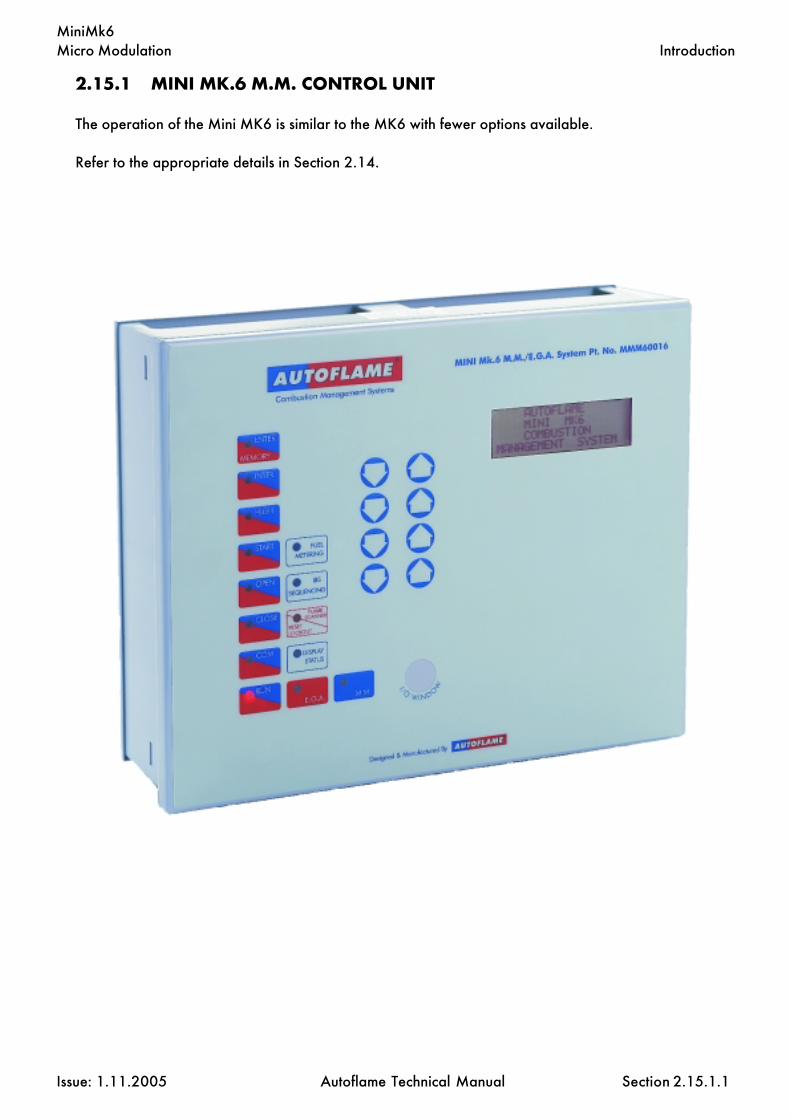
Micro Modulation
Issue: 1.11.2005 Autoflame Technical Manual Section
MiniMk6
2.15.1 MINI MK.6 M.M. CONTROL UNIT
The operation of the Mini MK6 is similar to the MK6 with fewer options available.
Refer to the appropriate details in Section 2.14.
2.15.1.1
Introduction

Micro Modulation
Issue: 1.11.2005 Autoflame Technical Manual Section
MiniMk6
2.15.2 MINI MK.6 COMMISSIONING
2.15.2.1 Options
To Select Options Mode.Ch1, Ch2, & Ch3 etc. refer to the rows of buttons respectively starting with CH1 at thetop.
Option values can be changed by entering the Option mode. The password must first be entered. Toenter the password follow the steps listed:
Either deselect and then select fuel or power down and then up
If system is already commissioned, press before the COM l.e.d. stops flashing
If system is not already commissioned, commissioning mode will be set automatically
The password screen is displayed:
Use the CH1 and CH2 buttons to set the Password codes. Then press
To select the Options screen, Press the Ch1 buttons simultaneously. The following screenshould be displayed:
Rows 2, 3 & 4 display textual descriptions of the option number and value
To change the Option number use the CH2 buttons
To change the value use CH3 buttons
Any number of Option values can be changed when in Option mode
When changes have been made press
All new Option values are then permanently stored
2.15.2.1.1
Commissioning: Options
ENTER
MEMORY
COM
CLOSE

Micro Modulation
Issue: 1.11.2005 Autoflame Technical Manual Section
MiniMk6
1. 3 Boiler temperature/pressure sensor type:
3 Temperature sensor (MM10006 & 7) 20-390 C (50 - 730 F)4 Unused5 Unused6 Medium pressure sensor (MM10008) 2.0 - 23.0 bar (30 - 330 P.S.I.)7 High pressure sensor (MM10009) 2.0 - 38.0 bar (30 - 550 P.S.I.)8 Low pressure sensor (MM10010) 0.2 - 3.80 bar (1.5 - 55 P.S.I.)9 Unused10 External temperature sensor (voltage input)- range set by parameters #52-5611 External pressure sensor (voltage input)- range set by parameters #52-56
2. 60 Motor travel speed during modulation: The value is not specific to a time/distance ratio. If the speed of the motor is too fast then increase this value. If tooslow, decrease the value. At times other than modulation the motors move at fullspeed or at the value set in option #75. Movement is limited by the slowestchannel, i.e. slowest moving motor.
5-240 Adjustment range 5 = 43 seconds from 00 to 900
60 = 120 seconds from 00 to 900
240 = 390 seconds from 00 to 900
3. 0 Unused: This option only applies to the mini Mk5.
4. 40 Unused: This option only applies to the mini Mk5.
5. 0 Purge position: This selects the purge position. (Applicable to channels 1-4when selected; see options #67-70). It also applies to post purge if option #118is set to a value greater than 0.
0 Selected Channel purges at HIGH position.(High Fire Position)1 Selected Channel purges at OPEN position.(Full span of servomotor as entered
during commissioning)
Option N
o.
Facto
ry Setti
ng
Option V
alue
Descrip
tion
2.15.2.1.2
Commissioning: Options

Micro Modulation
Issue: 1.11.2005 Autoflame Technical Manual Section
MiniMk6
Option N
o.
Facto
ry Setti
ng
Option V
alue
Descrip
tion
2.15.2.1.3
Commissioning: Options
6. 10 Proportional control (P): This option sets the proportional band. This is theoffset point at which the burner will begin to change modulation.
Example of proportional band offset: Required setpoint = 100 C, Proportionaloffset = 10 (i.e. option 6 set to value 10).
Proportional band: Value entered- Centigrade, Fahrenheit, Bar or PSI dependenton the type of control sensor used and display units selected- options #1 and #65.
5-250 If Centigrade, Fahrenheit or PSI units effective.0.5-25.0 If Bar units effective.
Note: Decreasing this value could lead to overshooting of the required setpoint.Increasing this value may cause the burner to modulate too early taking a longertime to reach the required setpoint.
7. 60 Integral control (I) time: Every n seconds 10% of the present offset fromsetpoint value is added or subtracted to the present proportional value. The valueof n is the number of seconds set in this option. It is possible to set this option to'off'. If 'off' is selected there will be no integral control. Parameter #106 enablesa % variation.
OFF-250 Seconds.
Note: Integral is equivalent to 'Reset'.
8. 1 Number of servomotor channels to be enabled: Channel "1" is alwaysenabled (Fuel Position Motor). Set option #8 to the number of additionalchannels required (Minimum of 1).
1 Channels 1 & 2 in use.2 Channels 1, 2 & 3 in use.3 Channels 1, 2, 3 & 4 in use.
Note: If option #8 is changed after commissioning then the M.M. unit will needto be recommissioned unless this option is returned to its previous value.
Minimum Flame
Maximum Flame
Proportional Offset
90 C(202 F)
100 C(212 F)

Micro Modulation
Issue: 1.11.2005 Autoflame Technical Manual Section
MiniMk6
Option N
o.
Facto
ry Setti
ng
Option V
alue
Descrip
tion
2.15.2.1.4
Commissioning: Options
9. 1 Internal stat operation: The 'internal stat' serves the purpose of turning theburner on and off according to the actual value relative to the required setpoint.There are three settings for this option. The first keeps the 'internal stat' closed allthe time. In this instance, a 'working stat’ must be fitted to the boiler. The secondsetting opens the 'internal stat' at an offset above the required setpoint and closesit at an offset below the required setpoint. The third setting opens the 'internal stat'at an offset above the required setpoint and closes it at an offset also above therequired setpoint. The following diagrams illustrate this operation. The offsetvalues are set in options #10 and #11.
0 Internal stat always closed.1 Burner starts below required setpoint.2 Burner starts above required setpoint.
10. 3 Offset above required setpoint at which the burner is stopped:(Only relevant if option #9 is set to 1 or 2).
2-50 If Centigrade, Fahrenheit or PSI units effective.0.2-5.0 If Bar units effective.
11. 3 Offset below/above required setpoint at which the burner isstarted:(Only relevant if option #9 is set to 1 or 2).
2-50 If Centigrade, Fahrenheit or PSI units effective.0.2-5.0 If Bar units effective.
Offset = 3 (value set in option #11)
Option #9 = 2, example using 100 C (212 F). Required setpoint.
Option #9 = 1, example using 100 C (212 F). Required setpoint.
Burner stops at this point and above
Required Value 100 C(212 F)
97 C(209 F)
103 C(215 F)
Burner starts at this point and below
Required Value 100 C(212 F)
103 C(215 F )
106 C(218 F)
Burner starts at this point and below
Burner stops at this point and above
Offset = 6 (value set in option #10)
Offset = 3 (value set in option #11)
Offset = 3 (value set in option #10)

Micro Modulation
Issue: 1.11.2005 Autoflame Technical Manual Section
MiniMk6
12. 0 E.G.A. Options: There are numerous E.G.A. Options, briefly they are as follows:-The E.G.A. is operational and the system trims. If the E.G.A. develops a fault, thesystem reverts to M.M. only operation. The system can be further optioned so thatin the event of an E.G.A. error the 'CR' relay will open and stop the burner. If thistype of option is set, the 'CR' relay will not close until the E.G.A. has cooled downto it's operating temperature. Further Options can be set which perform limit checkson the values that the E.G.A. measures. In the event of a limit being exceeded thesystem can revert to M.M. only operation, alternatively the 'CR' relay can beoptioned to open. A last Option exists to enable an E.G.A. to give readings on theM.M. for just monitor purposes. i.e. the system is commissioned on M.M. only butE.G.A. values are displayed just for information. All Option values except 0 makethe E.G.A. operational. If Options 5 or 6 are selected , refer to Options 19-27 toset limits to be tested for.
0 E.G.A. not optioned.1 System reverts to M.M. only operation if E.G.A. error.2 'CR1' relay opens if E.G.A. error.3 Unused.4 Unused.5 Limits tested, system reverts to M.M. only operation if E.G.A. error or limit e x -
ceeded.6 Limits tested, 'CR' relay opens if E.G.A. error or limit exceeded.7 System commissioned on M.M. only, E.G.A. used as monitor.
13. 0 Restore Factory Settings: To set all Options back to their original factory setvalues, set Option 13 value to 26 and press enter.
0-30
14. 0 Twin Burner Systems : Twin Burner Operation enables two burners to run at thesame time and with equal input. 14=1 The burners are identified with identificationnumbers e.g. 1 and 2 (See Option 33). If one of the burners develops a fault, thenboth burners are shut down. Only one load detector is required, this is connectedto the odd numbered burner. 14=2. One or the other burner can be firedindependently. If they are fired at the same time they synchronise together. Loaddetectors are required on both units. N.B. The Burner Control Circuit inputs and lowposition proving signals (T84 outputs) may have to be cross coupled depending onthe application.
0 Normal single burner operation.1 Twin Burner Operation - Both burners always fire together.2 Twin Burner Operation - Burners can run individually or together.
15. Unused.
Option N
o.
Facto
ry Setti
ng
Option V
alue
Descrip
tion
2.15.2.1.5
Commissioning: Options

Micro Modulation
Issue: 1.11.2005 Autoflame Technical Manual Section
MiniMk6
16. 0 Sequencing/DTI: If Option 16 is set to values 1 or 3, then this M.M. will respondto sequencing commands (See section on Sequencing). A lead boiler can beselected by connecting line voltage to terminal 88 of the appropriate M.M.. Only1 M.M. may be selected at a time or the sequencing will not operate. Alternativelythe lead boiler can be selected via the D.T.I. For this to be effective all the M.M.son the system must have terminal 88 volt free.
0 No sequencing.1 Sequencing enabled.2 Setpoint & enable/disable commands accepted from D.T.I.3 Both of 1 & 2.
17. 0 NO & CO displayed when running on oil: If fuel 2,3 or 4 are selected, thenthe displaying of CO & NO can be on or off. This Option is only relevant if an E.G.A.is operational on the system.
0 NO & CO display always zero.1 NO & CO is displayed normally.
18. 1 Carry forward of Trim: When the system modulates, the correction that may beexisting on the air damper position can be carried forward. Only air plus correctionis carried forward. This Option is only relevant if an E.G.A. is operational on thesystem.
0 No carry forward of trim.1 Trim carried forward.
19. 0 Upper offset limit % O2.E.G.A. Limits: Options 19-27 are only relevant if an E.G.A. is operational on thesystem. Option 12 value 5 or 6 must be selected if any of the following limit checksare to be invoked. To enable the checking of a particular limit, make the value ofthe appropriate Option a non-zero value. The amount of 'limit offset' is specified bythe value entered. e.g. If the 'upper limit offset O2' is to be enabled and the valueof the offset is 2.0%, then enter the value of 2.0 for Option No. 19.
0-10.0 % O2.
20. 0 Upper offset limit % CO2.0-10.0 % CO2
21. 0 Upper offset limit CO (Multiply entered value by 10 to get offset value in ppm).0-200 CO
22. 0 Lower offset limit % O20-10.0 % O2
Option N
o.
Facto
ry Setti
ng
Option V
alue
Descrip
tion
2.15.2.1.6
Commissioning: Options

Micro Modulation
Issue: 1.11.2005 Autoflame Technical Manual Section
MiniMk6
23. 0 Lower offset limit % CO20-10.0 % CO2
24. Unused.
25. 0 Absolute value % O2 .(System checks for O2 values lower than value specifiedin this Option).
0-20.0 % O2
26. 0 Absolute value % CO2. (System checks for CO2 values higher than valuespecified in this Option).
0-20.0 % CO2
27. 0 Absolute value ppm CO. (Multiply value entered by 10 to get actual ppmvalue). System checks for CO readings higher than values specified in this Option.
0-200 CO ppm
28. 20 Trim threshold: This option is only relevant if an E.G.A. is operational on thesystem. The value set in this Option is subtracted from the operator set "Required"value. If the Actual value is less than the result then no Trim action will be effected.If the trim is to be effective all the time then set the value to zero. Must also be setto O for the EGA to operate when external modulation is optioned.
0-50 If Centigrade, Fahrenheit or p.s.i. units effective.0-5.0 If Bar units effective.
29. 1 Golden Start: NB. Must be entered on each fuel individually if more than onefuel is commissioned. Refer to section 2.14.12 for further details.
0 Golden Start operates.1 Golden Start does not operate.
30. 50 D.T.I. - Required Value Minimum Limit: If the system is being used with a D.T.I.a maximum and minimum limit for the Required value must be set. The M.M. willonly act on values within the limits set. If a value is received from the D.T.I., that isoutside these limits, it will be ignored and the system uses its previous Requiredvalue. Practical range is limited to range of sensor selected.
5-995 If Centigrade, Fahrenheit or p.s.i. units effective.0.5-99.5 If Bar units effective.
31. 100 Maximum Limit.
5-995 If Centigrade, Fahrenheit or p.s.i. units effective.0.5-99.5 If Bar units effective.
Option N
o.
Facto
ry Setti
ng
Option V
alue
Descrip
tion
2.15.2.1.7
Commissioning: Options

Micro Modulation
Issue: 1.11.2005 Autoflame Technical Manual Section
MiniMk6
32. 20 Trim Delay: After ignition the sampling system does not sample for the period oftime set in this option. (Only relevant if E.G.A. is operational on system). This allowsfor the boiler to warm up and combustion to stabilise before sampling commences.
0-250 Period (seconds) after ignition no sampling takes place.
33. 1 MM Identification No. - Sequencing Options: If this M.M. is configured as partof a sequencing system and/or required to communicate with a D.T.I. then thefollowing three options must be set: The first is an identification number for thisM.M.. The second is the rating of the burner, and the third is the "sequencing scantime". Refer to Sequencing Section for further explanation.
1-10 Identification Number.
34. 5 Rating of burner
1-999 See option 77 for units.
35. 10 Sequence Scan Time. (minutes)
1-100 Sequence Scan time (Minutes).
36. 0 E.G.A. Sensor Selection: Available when using an E.G.A. System fitted withNO/SO2sensors. The following option is for selecting the type of Sensor required:Part No. EGA20005 for NO; EGA20006 for SO2.
SO2 NO0 Off Off1 Off On2 On Off3 On On
37. 0 Time Between ReadingsExplanation of D. (Derivative Action): The user adjustable control variablesto set up the D action are as detailed below. (Derivative is equivalent to 'Rate')
0 (0=off)1-200 Seconds. The time interval between the controller comparing Actual and Required
Setpoint values.
38. 2 Deadband. The Deadband is the margin above and below the Setpoint withinwhich no derivative control action occurs.
0-15 If Centigrade, Fahrenheit or PSI units optioned.0-1.5 If Bar units optioned.
Option N
o.
Facto
ry Setti
ng
Option V
alue
Descrip
tion
2.15.2.1.8
Commissioning: Options

Micro Modulation
Issue: 1.11.2005 Autoflame Technical Manual Section
MiniMk6
39. 10 Response Sensitivity.1-100 %
The Sensitivity Number indicates the amount of percentage firing rate increase ordecrease that is inflicted by the Derivative action;
e.g. If the chosen value was 10% then 10% of the maximum firing rate would beadded to the existing rate of fire; i.e.: If the burner were firing at 50% load and thederivative action was triggered the firing rate would increase by 10+50 to 60%.
The following is an example of the above control philosophy in action:
Note: “Time Between Readings” set to 20 seconds.“Deadband” set to 2°C (2°F.)"Response Sensitivity” set to 10%.
Setpoint Information:“Required” set to 90°C (190°F.)“Actual” reads 86°C (186°F.)
Firing Rate Information:Burner firing at 50% of capacity.
In the example situation there has been 4°C (4°F) drop in temperature below the“Required” value. The Deadband is set at 2°C (2°F.), therefore the Derivativeaction will be triggered as the deviation from Setpoint is in excess of 2°C (2°F.).In this example 10% will be added to the 50% firing rate resulting in an increasein firing rate to 60% of capacity. The “Time Between Readings” is set for 20 seconds and if after this time intervalthe “Actual” reading is not within the 2°C (2°F) deviation from “Required”Deadband another 10% would be added to the 60% firing rate which would resultin a 70% firing rate.By careful selection of “Time Between Readings” “Deadband” and “ResponseSensitivity” an ideal response to rate of change over time can be configured.The control philosophy detailed operates inversely if the “Actual” temperatureexceeds the Setpoint and is outside the “Deadband”.To enable or switch on the Derivative action the “Time Between Readings” must beset in excess of 10 seconds.
40. 0 Warming Facility for Low Pressure Steam IBS. For applications without anon return valve, IBS Warming will not operate on reduced setpoint. The facilityexists to install a thermostat in the boiler shell, and an input on Terminal 93 initiatesWarming.
0 Disabled1 Enabled
Option N
o.
Facto
ry Setti
ng
Option V
alue
Descrip
tion
2.15.2.1.9
Commissioning: Options

Micro Modulation
Issue: 1.11.2005 Autoflame Technical Manual Section
MiniMk6
41. 0 Steam Boiler SequencingOptions 41, 42, 43 and 44 are related to the "Standby Warming" Sequencingstate. Option 42 enables an offset to be set relative to the Required value togenerate a "phantom setpoint". During this "Standby Warming" operation theBoiler Control Circuit relay operates on the phantom setpoint. Options 43 and 44are offset values above and below the phantom setpoint (i.e. Options 10 and 11are not used for the phantom setpoint Boiler Control Circuit relay offsets). Whena boiler is set to the "Standby Warming" state, by the M.M. Sequencing commands,it runs for a period of time at low flame and then off for a period. This action keepsthe boiler warm. Option 53 sets the time interval that the burner is Off: Option 54sets the time that the burner is On. If Option 41 = 0 only one boiler will be set tothe "Standby Warming" state. Boilers further down the sequence will be set to the"OFF" state. In this case Options 53 and 54 set the ON and OFF time. (If Options41 and 53 are 0 then Hot Water Sequencing is implemented).
0 3 State Steam Sequencing. ON, Standby/Warming , Off1 2 State Steam Sequencing. ON, Standby/Warming
42. 20 Phantom Setpoint. Offset below normal Required value.
0-100 If Centigrade, Fahrenheit or p.s.i. units effective.0-10.0 If Bar units effective.
43. 5 Offset above phantom setpoint when Boiler Control Circuit opens.2-50 If Centigrade, Fahrenheit or p.s.i. units effective.0.2-5.0 If Bar units effective.
44. 5 Offset below phantom setpoint when Boiler Control Circuit closes.2-50 If Centigrade, Fahrenheit or p.s.i. units effective.0.2-5.0 If Bar units effective.
45. 0 External Modulation: If this option is enabled, the usual P.I.D. control isdisabled and the percentage of firing is set by an external controller applied to theappropriate input (terminals 7,8 & 9). This can be 0-10V, 2-10V, 0-20mA or 4-20mA representing low to high fire. See Parameter 69. The 10 point flow meteringcalibration must be entered for correct operation. See Option 57. Set Option 9 to0 and fit both a working stat and high limit stat to turn the burner on and off.
0 Disabled1 Enabled - input from auxilliary analogue input
46. 0 Actual value displayed during External Modulation. Load sensor inputrequired to display Actual value.
0 Required and Actual values displayed1 Required and Actual values not displayed
Option N
o.
Facto
ry Setti
ng
Option V
alue
Descrip
tion
2.15.2.1.10
Commissioning: Options

Micro Modulation
Issue: 1.11.2005 Autoflame Technical Manual Section
MiniMk6
47. 0 Cold Start Routine. If the boiler temperature/pressure is at or below 30% ofthe target pressure/temperature then the burner would be held at low flame. Ifthe boiler is at or below 60% of its target temperature/pressure then the burnerfiring rate would be held at 50% firing. When the boiler temperature/pressureexceeds the P Band offset in the PID philosophy then the burner would revert tonormal PID load control.
0 Off1 On
48. 0 0-120 Flue Gas Recirculation - Timer. This is the time that the MM elements (posi-tioning motors/ac drives) are held at the FGR positions, after which modulationthen takes place.
49. 0 0-50 Flue Gas Recirculation - Offset. This is an offset from the required value.The FGR positions are held until such time that the actual value reaches theoffset value.
50. 0 Flue Gas Recirculation - Flue Gas Tempertature.0 Not optioned.1 Optioned. The FGR positions are held until such time as the flue gas tempera-
ture has reached 120°C. (An EGA must be present and optioned)..
51. 0 Units of Temperature. NB. When changing units adjust all other relevantoptions respectively.
0 All temperature readings displayed in Celsius.1 All temperature readings displayed in Fahrenheit.
52. 0 Units of Pressure. NB. When changing units adjust all other relevant optionsrespectively.
0 All pressure readings displayed in Bar.1 All pressure readings displayed in p.s.i.
53. 1 Steam Boiler Sequencing Burner Off Time: The steam boiler type sequenc-ing is enabled by setting Option 1 to a respective pressure sensor. Options 42, 43and 44 are relevant to the "Standby" boiler operation.
1-200 Burner "Off" time (minutes) during warm up cycle.(Intelligent Boiler Sequencing. Steam boiler applications).
54. 5 Burner 'On' Time1-30 Burner "On" time (minutes) during warm up cycle. (Intelligent Boiler Sequencing.
Steam boiler applications).
55. 0 Internal PID/External Modulation Selectible using terminal 88.(Cannot be used with Sequencing/IBS)
0 Normal operation, Internal PID or External Modulation if Option 45=1.1 Terminal 88 = 0 V - internal PID.
Terminal 88 = Line Voltage - External Modulation, CR1 always closed.
Option N
o.
Facto
ry Setti
ng
Option V
alue
Descrip
tion
2.15.2.1.11
Commissioning: Options

Micro Modulation
Issue: 1.11.2005 Autoflame Technical Manual Section
MiniMk6
56. 1 Operation of Alarm Output, Terminal No 79., NB this is a switchedneutral and not a voltage output terminal:
1 Relay normally Off, On when Alarm.2 Relay normally On, Off when alarm.
57. 0 Flow Metering: If the Air window shows 57 and the Required window shows 1when ENTER is pressed to store the Options then the 10 point calibrationprocedure will be invoked the next time the burner starts.
0 No Flow Metering.1 Flow Metering Operates.2 Totalised Flow Metering reset to zero for fuel selected
58. 15 Flow Metering Calculation Delay. Number of seconds from ignition to flowmetering calculation starts.
0-60 Seconds.
59. Unused.
60. 0 Hand/Auto Bumpless Transfer Operation.0 Fuel valve goes directly to last set Hand position.1 Hand position (taken on present fuel valve position when changing from Auto to
Hand operation).2 As 0, but Hand position is not stored in permanent memory.
61. 1 Flow metering units fuel 1 - Gaseous0 Cubic feet1 Cubic meters2 Kilograms3 Litres4 US gallons
62. 3 Flow metering units fuel 2 - Liquid0 Cubic feet1 Cubic meters2 Kilograms3 Litres4 US gallons
63. 3 Flow metering units fuel 3 - Liquid0 Cubic feet1 Cubic meters2 Kilograms3 Litres4 US gallons
Option N
o.
Facto
ry Setti
ng
Option V
alue
Descrip
tion
2.15.2.1.12
Commissioning: Options

Micro Modulation
Issue: 1.11.2005 Autoflame Technical Manual Section
MiniMk6
64. 1 Flow metering units fuel 4 - Gaseous0 Cubic feet1 Cubic meters2 Kilograms3 Litres4 US gallons
65-66. Unused.
67. 1 Purge Position: The following Options tell the M.M. which channels are to beincluded in the Purge sequence. (See Option 5 for Purge Position).
0 Channel 1 to Purge position.1 Channel 1 to remain closed for Purge.
68. 0 Channel 2 Purge position.0 Channel 2 to Purge position.1 Channel 2 to remain closed for Purge.
69. 0 Channel 3 Purge position.0 Channel 3 to Purge position.1 Channel 3 to remain closed for Purge.
70. 0 Channel 4 Purge position.0 Channel 4 to Purge position.1 Channel 4 to remain closed for Purge.
71. 0 Fuel 1 - Fuel type.0 Natural gas3 Fuel 1
Do not use any other values.
72. 1 Fuel 2 - Fuel type.1 Light Distillate Oil2 Heavy Fuel Oil3 Fuel 2
Do not use any other values.
73. 1 Fuel 3 - Fuel type.1 Light Distillate Oil2 Heavy Fuel Oil3 Fuel 3
Do not use any other values.
74. 0 Fuel 4 - Fuel type.0 Natural gas3 Fuel 4
Do not use any other values.
Option N
o.
Facto
ry Setti
ng
Option V
alue
Descrip
tion
2.15.2.1.13
Commissioning: Options

Micro Modulation
Issue: 1.11.2005 Autoflame Technical Manual Section
MiniMk6
75. 0 Purge Motor Travel Speed: During a Purge Sequence the Motor Travel Speedcan be set independent of Option 2. This affects all selected channels.
0 -100 0 = Quickest time,100 = Slowest time.
76. 0 Unused.
77. 0 Burner Rating Units.Display purposes only for Flow Metering.0 KW x 100 /hr1 Kg x 100 /hr2 MW /hr3 Btu x100 /hr4 Hp x100 /hr5 lbs x 100 /hr
78-85. Unused.
86. 0 Channel 1 Softened Error checking Select - increases positioning error fom0.1° to 0.5° for Industrial motor
0 CH1 normal positioning motor.1 CH1 industrial positioning motor/softened error checking.
87. 0 Channel 2 Softened Error checking Select .0 CH2 normal positioning motor.1 CH2 industrial positioning motor/softened error checking.
88. 0 Channel 3 Softened Error checking Select.0 CH3 normal positioning motor.1 CH3 industrial positioning motor/softened error checking.
89. 0 Channel 4 Softened Error checking Select .0 CH4 normal positioning motor.1 CH4 industrial positioning motor/softened error checking.
90-109. Unused.
110. 1 Burner control.1 Internal - Standard Scanner2 Internal - Self-check Scanner
111. 0 Pilot0 Interrupted pilot1 Intermittant pilot (expanding flame)
Option N
o.
Facto
ry Setti
ng
Option V
alue
Descrip
tion
2.15.2.1.14
Commissioning: Options

Micro Modulation
Issue: 1.11.2005 Autoflame Technical Manual Section
MiniMk6
112. 40 Pre purge time20-100 Seconds
113. 3 Pre ignition time. Time ignition transformer is on before gas valve opens.3-5 Seconds
114. 3 First safety time. Time pilot valve is open before UV is checked.3-10 Seconds
115. 3 Pilot prove time. (Pilot trial for ignition PTFI)3-5 Seconds
116. 3 Fuel 1 & Fuel 4 Second safety time (Main trial for ignition MTFI).(Not Applicable to expanding flame - see option 111)
3-10 Seconds
117. 5 Main flame prove time.5-20 Seconds
118. 0 Post purge time0-100 Seconds (0 - No post purge)
119. 10 Control Box Recycle time. Time delay from burner shut down to startup.3-120 Seconds
120. 10 UV Threshold5-50 Flame Signal Strength below which considered to be flame failure.
121. 5 Delay from start of pre-purge after which air switch checked5-10 Seconds
122. Unused.
123. 3 Fuel 2 & Fuel 3 Second safety time (Main trial for ignition MTFI).(Not Applicable to expanding flame - see option 111)
3-15 Seconds
124. 1 Gas valve proving pressure sensor type:
0 Nominal range 0–25" w.g./ 0–65 mbar/ 0–1 psi (Sensor MM60006)Note. PSI display not available with this sensor
1 Nominal range 0–135"w.g./ 0–340 mbar/ 0–5 psi (Sensor MM60008)2 Nominal range 0–300"w.g./ 0–750 mbar/ 0–11 psi (Sensor MM60011)3 Nominal range 0–550"w.g./ 0–1380 mbar/ 0–20 psi (Sensor MM60012)4 Nominal Range 0-1650”w.g/0-4125 mbar/0-60psi (Sensor MM60014)
Option N
o.
Facto
ry Setti
ng
Option V
alue
Descrip
tion
2.15.2.1.15
Commissioning: Options
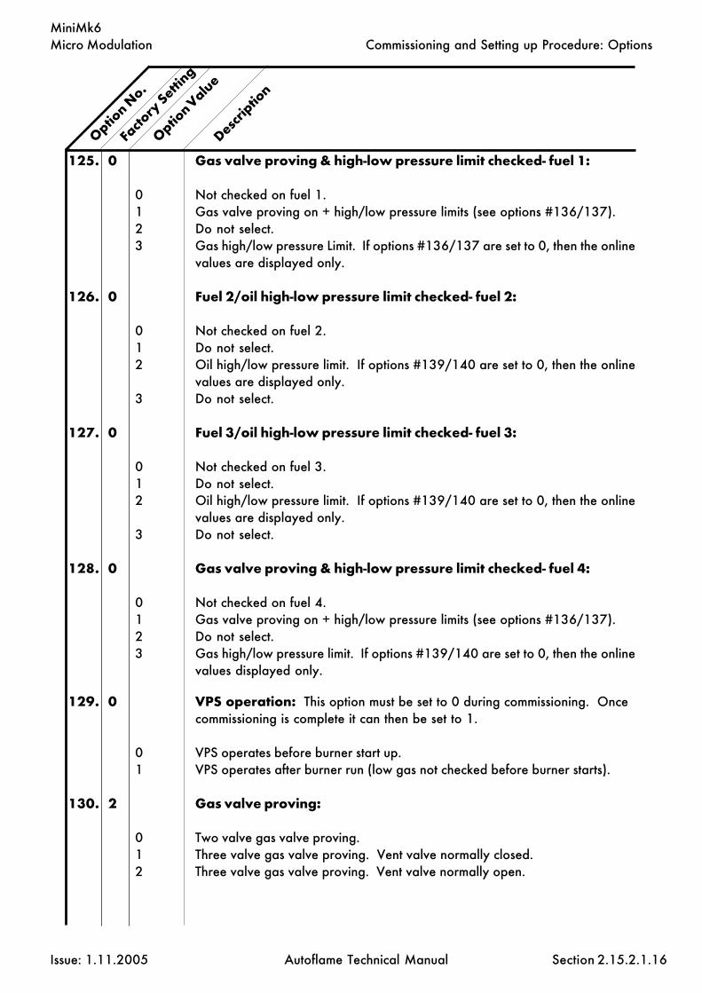
Micro Modulation
Issue: 1.11.2005 Autoflame Technical Manual Section
MiniMk6
125. 0 Gas valve proving & high-low pressure limit checked- fuel 1:
0 Not checked on fuel 1.1 Gas valve proving on + high/low pressure limits (see options #136/137).2 Do not select.3 Gas high/low pressure Limit. If options #136/137 are set to 0, then the online
values are displayed only.
126. 0 Fuel 2/oil high-low pressure limit checked- fuel 2:
0 Not checked on fuel 2.1 Do not select.2 Oil high/low pressure limit. If options #139/140 are set to 0, then the online
values are displayed only.3 Do not select.
127. 0 Fuel 3/oil high-low pressure limit checked- fuel 3:
0 Not checked on fuel 3.1 Do not select.2 Oil high/low pressure limit. If options #139/140 are set to 0, then the online
values are displayed only.3 Do not select.
128. 0 Gas valve proving & high-low pressure limit checked- fuel 4:
0 Not checked on fuel 4.1 Gas valve proving on + high/low pressure limits (see options #136/137).2 Do not select.3 Gas high/low pressure limit. If options #139/140 are set to 0, then the online
values displayed only.
129. 0 VPS operation: This option must be set to 0 during commissioning. Oncecommissioning is complete it can then be set to 1.
0 VPS operates before burner start up.1 VPS operates after burner run (low gas not checked before burner starts).
130. 2 Gas valve proving:
0 Two valve gas valve proving.1 Three valve gas valve proving. Vent valve normally closed.2 Three valve gas valve proving. Vent valve normally open.
Option N
o.
Facto
ry Setti
ng
Option Valu
e
Descrip
tion
2.15.2.1.16
Commissioning and Setting up Procedure: Options
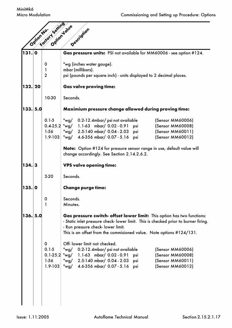
Micro Modulation
Issue: 1.11.2005 Autoflame Technical Manual Section
MiniMk6
131. 0 Gas pressure units: PSI not available for MM60006 - see option #124.
0 "wg (inches water gauge).1 mbar (millibars).2 psi (pounds per square inch) - units displayed to 2 decimal places.
132. 20 Gas valve proving time:
10-30 Seconds.
133. 5.0 Maximium pressure change allowed during proving time:
0.1-5 "wg/ 0.2-12.4mbar/ psi not available (Sensor MM60006)0.4-25.2 "wg/ 1.1-63 mbar/ 0.02 - 0.91 psi (Sensor MM60008)1-56 "wg/ 2.5-140 mbar/ 0.04 - 2.03 psi (Sensor MM60011)1.9-103 "wg/ 4.6-356 mbar/ 0.07 - 5.16 psi (Sensor MM60012)
Note: Option #124 for pressure sensor range in use, default value willchange accordingly. See Section 2.14.2.6.2.
134. 3 VPS valve opening time:
3-20 Seconds.
135. 0 Change purge time:
0 Seconds.1 Minutes.
136. 5.0 Gas pressure switch- offset lower limit: This option has two functions:- Static inlet pressure check- lower limit. This is checked prior to burner firing.- Run pressure check- lower limit.This is an offset from the commisioned value. Note options #124/131.
0 Off- lower limit not checked.0.1-5 "wg/ 0.2-12.4mbar/ psi not available (Sensor MM60006)0.1-25.2 "wg/ 1.1-63 mbar/ 0.02 - 0.91 psi (Sensor MM60008)1-56 "wg/ 2.5-140 mbar/ 0.04 - 2.03 psi (Sensor MM60011)1.9-103 "wg/ 4.6-356 mbar/ 0.07 - 5.16 psi (Sensor MM60012)
Option N
o.
Facto
ry Setti
ng
Option Valu
e
Descrip
tion
2.15.2.1.17
Commissioning and Setting up Procedure: Options
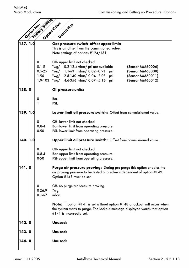
Micro Modulation
Issue: 1.11.2005 Autoflame Technical Manual Section
MiniMk6
Option N
o.
Descrip
tion
Facto
ry Setti
ng
Option Valu
e
137. 1.0 Gas pressure switch- offset upper limit:This is an offset from the commisioned value.Note settings of options #124/131.
0 Off- upper limit not checked.0.1-5 "wg/ 0.2-12.4mbar/ psi not available (Sensor MM60006)0.5-25 "wg/ 1.1-63 mbar/ 0.02 - 0.91 psi (Sensor MM60008)1-56 "wg/ 2.5-140 mbar/ 0.04 - 2.03 psi (Sensor MM60011)1.9-103 "wg/ 4.6-356 mbar/ 0.07 - 5.16 psi (Sensor MM60012)
138. 0 Oil pressure units:
0 Bar.1 PSI.
139. 1.0 Lower limit oil pressure switch: Offset from commissioned value.
0 Off- lower limit not checked.0.8-4 Bar- lower limit from operating pressure.0-50 PSI- lower limit from operating pressure.
140. 1.0 Upper limit oil pressure switch: Offset from commissioned value.
0 Off- upper limit not checked.0.8-4 Bar- upper limit from operating pressure.0-50 PSI- upper limit from operating pressure.
141. 0 Purge air pressure proving: During pre purge this option enables theair proving pressure to be tested at a value independent of option #149.Option #148 must be set.
0 Off- no purge air pressure proving.0-26.9 “wg.0.1-67 mbar.
Note: If option #141 is set without option #148 a lockout will occur whenthe system starts to purge. The lockout message displayed warns that option#141 is incorrectly set.
142. 0 Unused:
143. 0 Unused:
144. 0 Unused:
2.15.2.1.18
Commissioning and Setting up Procedure: Options

Micro Modulation
Issue: 1.11.2005 Autoflame Technical Manual Section
MiniMk6
Option N
o.
Descrip
tion
Facto
ry Setti
ng
Option Valu
e
145. 0 Autoflame air pressure sensor:
0 Autoflame air pressure sensor not optioned.1 Autoflame air pressure sensor optioned 0-1 PSI (Sensor MM60005)2 Autoflame air pressure sensor optioned 0-2 PSI (Sensor MM60013)
146. 0 Air pressure units:
0 "wg.1 mBar.
147. 0 Air sensor error checking window: Only active during modulation(error #82). The burner will shut down if outside the window.
0 No error checking.0 - 3 "wg (maximum = +/- 3 "wg).0 - 7.5 mbar (maximum = +/- 7.5 mbar).
148. 0 Autoflame air proving selected:
0 Not used- requires external air proving switch on terminal #54.1 Air proving- requires Autoflame air pressure sensor.2 As 1 but terminal #54 also used if fuel 2 selected (for atomising air).
149. 0.3 Minimum air pressure proving value: Air pressure switch function.
0.3 - 4.9 " wg.1 - 12.5 mbar.
150. 0 Clear ALL commissioning data and gas/air sensor re-commission:
0 - 10 Range.5 Clear commissioning data- restore options/parameters to factory settings.7 Air sensor automatic recomission (see section 2.14.18.1 in the technical
manual for more information).8 Gas sensor automatic recommision (see section 2.14.18.2 in the technical
manual for more information).
2.15.2.1.19
Commissioning and Setting up Procedure: Options

Micro Modulation
Issue: 1.11.2005 Autoflame Technical Manual Section
MiniMk6
Option N
o.
Descrip
tion
Facto
ry Setti
ng
Option Valu
e
For safety reasons, options #110-150 alsohave to be entered in as parameters.It is the responsibility of the commissioningEngineer to ensure that all settings are set inaccordance with the appropriate standards,local codes and practices, e.t.c.
If the M.M. system is stuck in the ‘idle’ condition, it is likelythat options #110-150 are not identical to parameters#110-150. If the commissioning mode is entered, therelevant options/parameters not set correctly will bedisplayed at the bottom of the screen. If more than 1option/parameter is not set correctly, these will bedisplayed in numerical order, i.e. on entering thecommissioning mode again the next sequential option/parameter not set correctly will be displayed.
2.15.2.1.20
Commissioning and Setting up Procedure: Options

Micro Modulation
Issue: 1.11.2005 Autoflame Technical Manual Section
MiniMk6
2.15.2.2 Parameters
To Select Parameter Mode.Ch1, Ch2, Ch3 refer to the rows of buttons respectively starting with CH1 at the top.
Parameter values can be changed by entering the Parameter mode. The password must first be entered.To enter the password follow the steps listed.
Either deselect and then select fuel or power down and then up.
If system is already commissioned, press before the COM l.e.d. stops flashing.
If system is not already commissioned, commissioning mode will be set automatically.
The password screen is displayed.
Use the CH1 and CH2 buttons to set the Password codes. Then pressand buttons simultaneously.
The parameters screen will then be displayed as below:
Rows 2, 3 & 4 display textual descriptions of the parameter number and value.
To change Parameter number use the CH2 buttons.
To change value use the CH3 buttons.
Any number of Parameter values can be changed when in Parameter mode.
When changes have been made press
All new Parameter values are then permanently stored.
The operation of the Mini MK6 parameters are similar to the MK6. For further information refer to section2.14.2.5.
COM
CLOSEOPEN
ENTER
MEMORY
Commissioning: Parameters
2.15.2.2.1

Micro Modulation
Issue: 1.11.2005 Autoflame Technical Manual Section
MiniMk6
2.15.2.3 Fuel Flow Metering
1. Go to Options, set Option 57 to 1 (default 0).
2. When the above is displayed press , this will initiate the Flow Metering setup mode.
3. The next time the burner starts and reaches modulation, the M.M. will automatically go into the tenpoint setup mode for Flow Metering. The following screen will be displayed:
4. In this mode the display will show the channel 1 fuel valve position in degrees angular, and the flow
units which can be adjusted by using the third row of buttons.
Note:
a) The third row of text confirms to the commissioning engineer which of the 10 points arecurrently being measured.
b) The minimum numerical value for fuel flow that can be entered into memory is 0.01.The maximum numerical value for fuel flow that can be entered into memory is 999.99.
c) The values are entered in descending order, i.e. Point No.1 is maximum flame and PointNo.10 is at minimum flame. The 10 sequential points on the load index are allocatedautomatically by the M.M. All values are in units/minute.
5. When fuel flow has been calculated or read off of a commissioning fuel flow meter the value isentered as detailed in Point No.4.
T h e button is then pressed and the value is logged in the M.M. memory.
6. The above detailed data entry routine is repeated until all 10 points have flow values allocated tothem.
7. When the last (10th) point has been entered the burner continues to fire.
8. To display Fuel Flow Metering press button.
9. To reset the Totalised value to zero set Option 57 to 2, press while 57 and 2 are beingdisplayed.
10. To ensure maximum accuracy, Option 58 can be altered from its default value (15). This is thedelay time from the flame failure control box starting the combustion sequence to the main flamebeing established. (This option is only of relevance when an external burner control is being used).
Commissioning: Fuel Flow Metering
ENTER
MEMORY
ENTER
MEMORY
FUELMETERING
123123123
ENTER
MEMORY
2.15.2.3.1

Micro Modulation
Issue: 1.11.2005 Autoflame Technical Manual Section
MiniMk6
2.15.3 End User Day to Day Operation
2.15.3.1 Normal Run Operation
Upon initial selection of a commissioned fuel, a logo screen flashes up followed by the 'MM STATUS'display. The COM l.e.d. flashes for five seconds.
To adjust the Required value press and use the third row accordingly.
The same method of adjustment is used when the second setpoint is selected (via terminal 87).
The range of the required value is limited according to the type of sensor being used (See Option 1).
If the burner control circuit is closed the burner system will sequence through the burner start up proce-dure. The system purges and ignites, and twenty seconds (nominal) after ignition the system modulates.Values are displayed according to the selected screen. There are a number of possible screens asshown on the next page. To select one of the display modes just press:
Pressing the bottom row button will display the logo screen.
The respective l.e.d. will remain illuminated to indicate which mode is selected. The COM and E.G.A.modes are only selectable if an E.G.A. is optioned on the system.
In the event of the system being powered down, these selections will be memorised as is all commission-ing data, Options and required value. During normal run operation the RUN led is on all the time.When no fuels are selected only the RUN l.e.d. remains illuminated.
If an E.G.A. is operative on the system it will calibrate every time the burner starts and stops. WhenCOM or EGA display modes are selected CAL is displayed when the EGA is calibrating. If the E.G.A.is cooling, COOL is displayed. If the burner is not firing, EGA is displayed. When the burner is firingboth modes show E.G.A.. if the Actual value has not reached the value at which trimming is permitted.(See Option 28.) If an E.G.A. error has occurred the error code number is displayed if either of EGA orCOM modes are selected.
The software version number can be displayed by by pressing the Top CH1 buttons simul-taneously, when in the MM display mode.
End User Day to Day Operation
DISPLAYSTATUS
121212
COM
E.G.A
123123
M.M.
1212
DISPLAYSTATUS
123123
2.15.3.1.1
FLAMESCANNER
LOCKOUTRESET
ACDRIVE
123123
IBSSEQUENCING
123123
FUELMETERING
123123 OUTSIDE
TEMPCOMPENSATION
123123
This button also scrolls to the Valve Proving Screen

Micro Modulation
Issue: 1.11.2005 Autoflame Technical Manual Section
MiniMk6
Several different displays are available to provide the operator with information through start-up andnormal operation.
Selectable screens provide the following information:
2.15.3.1.2
End User Day to Day Operation
Startup/Fuel Select
Displayed at startup and when no fuel selected.
M.M. Status
Shows the angular value for each of the positioning motors,channels 1 to 4. The bottom row displays additional statusinformation, including Low Flame Hold, Hand Operation,Golden Start, FGR Start.
IBS Status
For a multi boiler installation, this screen shows which is thelead boiler plus information on temperature and pressure setpoints.
EGA On Line Values
When an Exhaust Gas Analyser (EGA) is included in the sys-tem, this screen shows the actual values of the gases beingmeasured in the flue plus the exhaust gas temperature, ambi-ent temperature, dT, and efficiency. A similar screen shows thecommissioned values.
Lockout History
Upto the last 16 lockouts are displayed here. Details includetime and date of lockout and reset, the cause of the lockoutand at what stage of the sequence the lockout occured. Onlyone lockout record can be displayed at a time. Press the flamescanner button to scroll through the records.
Fuel Metering Status
This screen displays which fuel is currently selected, the con-sumption at this point in time and the total fuel used to date.
System Status
This screen shows the present firing rate, which fuel is beingused, and the required/actual values.
History
The hours run and the number of startups for the currently se-lected fuel are displayed on this screen. The screen is selectedby pressing the display status button.
Burner Control Status / Time
Row 1 indicates the burner sequence state, row 2 gives theflame signal strength.

Micro Modulation
Issue: 1.11.2005 Autoflame Technical Manual Section
MiniMk6
2.15.3.2.1
End User Day to Day Operation
2.15.3.2 Routine Adjustments
Setting Time & Date
To adjust the time and date settings go into COM mode. Power down the unit and restart. The
LED will be flashing and you have 5 seconds to press it. Then the password screen is
displayed. Set password to: , Press
'Set Clock' screen is displayed:
Use the buttons as detailed below to adjust the values appropriately.
Channel 1 Day
Channel 2 Date
Channel 3 Month
Channel 4 Year
Hours
Minutes
When finished press the flashing button to submit to memory.
Note: Hours are displayed in 24 hour mode.
Adjusting the Screen Contrast
Hold down any of the screen select buttons,
and then use the top row to adjust the contrast accordingly.
COM
1010
ENTER
MEMORY
CLOSE
DISPLAYSTATUS
1212
M.M.
123123
E.G.A
1212
FUELMETERING
1212 IBS
SEQUENCING
1212 FLAME
SCANNERLOCKOUT
RESET
HIGH START
OPEN CLOSE

Micro Modulation
Issue: 1.11.2005 Autoflame Technical Manual Section
MiniMk6
Calibrating Actual Pressure Reading
A facility exists to adjust small errors in the pressure value displayed in the Actual window.
To increase the value press and the Ch3 simultaneously.
To decrease press and the CH3 . The facility does not work on temperature.
RUN
RUN
2.15.3.2.2
End User Day to Day Operation

Micro Modulation
Issue: 1.11.2005 Autoflame Technical Manual Section
MiniMk6
2.15.3.3.1
2.15.3.3 EPROM Version Numbers
To display the software version number select the MM Display screen, then press Channel 1 Up andDown simultaneously.
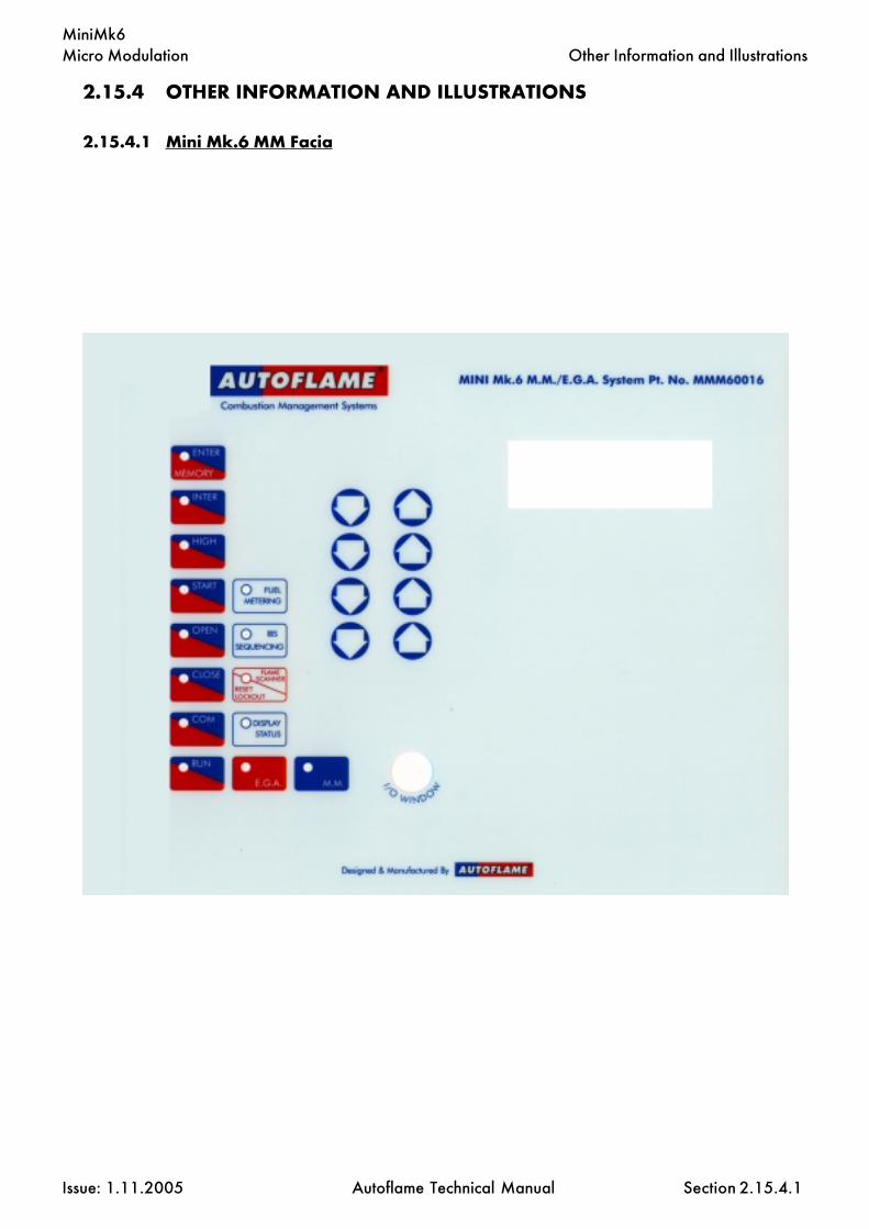
Micro Modulation
Issue: 1.11.2005 Autoflame Technical Manual Section
MiniMk6Other Information and Illustrations
2.15.4 OTHER INFORMATION AND ILLUSTRATIONS
2.15.4.1 Mini Mk.6 MM Facia
2.15.4.1

Micro Modulation
Issue: 1.11.2005 Autoflame Technical Manual Section
MiniMk6
2.15.4.2
2.15.4.2 Mini Mk.6 MM Enclosure Dimensions

Micro Modulation
Issue: 1.11.2005 Autoflame Technical Manual Section
MiniMk6
2.15.4.3 Schematic Connection Diagram
2.15.4.3
Other Information and Illustrations

Micro Modulation
Issue: 1.11.2005 Autoflame Technical Manual Section
MiniMk6
2.15.4.4 Mini Mk.6 Specifications
2.15.4.4 Classifications
Classification According to EN298 - F B L L J B
Mains Supply: 230V, +10%/-15% 120V, +10%/-15%
Climate: Temperature 0 to +550C (32 to 1310F)Humidity 0 to 90% non-condensing.
Protection Rating: The unit is designed to be panel mounted in any orientation and the front faciais IP65. The back of the unit is IP20.
Inputs & Outputs:230V Unit:
Outputs Terminal 57 250 mA Must be connected through contactor58 250 mA Must be connected through contactor59 1Amp, 0.6 power factor60 1Amp, 0.6 power factor61 1Amp, 0.6 power factor62 1Amp, 0.6 power factor63 1Amp, 0.6 power factor64 250mA To drive relay/lamp only78 100mA To drive relay only - switched neutral79 100mA To drive relay/lamp only - switched neutral
Analogue I/O.s 240 Ω or less.
120V Unit:
Outputs Terminal 57 250 mA Must be connected through contactor58 250 mA Must be connected through contactor59 2Amp, 0.6 power factor60 2Amp, 0.6 power factor61 2Amp, 0.6 power factor62 2Amp, 0.6 power factor63 2Amp, 0.6 power factor64 250mA78 100mA To drive relay only - switched neutral79 100mA To drive relay/lamp only -switchedneutral
Analogue I/O.s 240 Ω or less.
Note:
1- The low voltage connections are not safe to touch. Protection against electric shock is provided bycorrect installation.2- Cabling should be a maximum 25m.3- Use screened cable as specified in Section 2.14.2.9.4.4- The burner 'High Limit Stat' must be of the manual reset type.
Other Information and Illustrations
2.15.4.4
47.5 - 63 Hz, Unit max. power consumption 45W
Max
. loa
d 6
Am
p.M
ax. l
oad
6 A
mp.

Micro Modulation
Issue: 1.11.2005 Autoflame Technical Manual Section
MiniMk6
2.15.4.5.1
2.15.4.5.1 Mini Mk.6 Electrical Specifications
Other Information and Illustrations
1 Current Input, 0-20mA. For channel 4 VSD use only. Can be connected to the
current output of a VSD.
2 Voltage Input, 0-10V. For channel 4 VSD use only. Can be connected to the
voltage output of a VSD.
3 Common for terminals #1 and 2.
4 Unused.
5 Unused.
6 Common for terminals #4 and 5.
7 Current Input, 0-20mA. Used for external modulation.
8 Voltage Input, 0-10V. Used for external modulation.
9 Common for terminals #7 and 8.
10 Current Output, 4-20mA. For channel 5 VSD use only. Can be connected to the
current input of a VSD.
11 Voltage Output, 0-10V. For channel 5 VSD use only. Can be connected to the
voltage input of a VSD.
12 Common for terminals #10 and 11.
13 Unused.
14 Unused.
15 Unused.
16 Current Output, 4-20mA. Varies in accordance with firing rate.
17 Voltage Output, 0-10V. Varies in accordance with firing rate.
18 0V common for terminals #16 and 17.
Note that all the common terminals (3, 6, 9, 12, 15, 18) are connected to each other internally. Allof the circuitry, associated with the analogue inputs and outputs detailed above, is isolated fromearth/ground potential, i.e. floating.

Micro Modulation
Issue: 1.11.2005 Autoflame Technical Manual Section
MiniMk6
2.15.4.5.2
Other Information and Illustrations
19, 20 Unused.
21, 22 Connections to an Autoflame self check UV sensor.
23, 24 Communications port connections for twin burner operation.
25, 26 Communications port connections to an Exhaust Gas Analyser (E.G.A.).
27, 28 Communications port connections for DTI and/or IBS/lead-lag operation.
29, 30 Communications port (currently unassigned).
31, 32 Signal inputs from Autoflame air pressure sensor.
33 0V supply to Autoflame air/gas/oil pressure sensors.
34 +12V supply to Autoflame air/gas/oil pressure sensors.
35 Signal input from Autoflame oil pressure sensor.
35, 36 Signal inputs from Autoflame gas pressure sensor.
37, 38 Connections to an Autoflame boiler temperature detector.
37, 38, 39 Connections to an Autoflame boiler pressure detector.
40 0V supply to channel 1 and channel 2 positioning motors.
41 +12V supply to channel 1 and channel 2 positioning motors.
42 Signal from channel 1 positioning motor, indicating position.
43 Signal from channel 2 positioning motor, indicating position.
44 Signal from channel 3 positioning motor, indicating position.
45 Signal from channel 4 positioning motor, indicating position.
46 0V Supply to channel 3 and channel 4 positioning motors.
47 +12V Supply to channel 3 and channel 4 positioning motors.
48, 49 No terminals allocated.

Micro Modulation
Issue: 1.11.2005 Autoflame Technical Manual Section
MiniMk6
50,51 Connections to an Autoflame UV sensor.
52 Mains voltage input- external auxiliary delay to purge.
53 Mains voltage input- burner on/off signal. Running interlock circuit.
54 Mains voltage input- safety circuits, e.g. air proving.
55 Mains voltage input- proving circuits, e.g. gas valve proof of closure.
56 Mains voltage input- lockout reset.
57 Mains voltage output- call for heat.
58 Mains voltage output- burner motor.
59 Mains voltage output- start/pilot valve.
60 Mains voltage output- main fuel valve 1.
61 Mains voltage output- main fuel valve 2.
62 Mains voltage output- vent valve.
63 Mains voltage output- ignition transformer.
64 Unused.
65 No terminal allocated.
66 Mains supply- earth/ground.
67 Main supply- neutral.
68 Mains supply- live/hot.
69 Mains voltage output. Power to positioning motors.
70 Switched neutral- drives channel 1 positioning motor clockwise.
71 Switched neutral- drives channel 1 positioning motor counter clockwise.
72 Switched neutral- drives channel 2 positioning motor clockwise.
73 Switched neutral- drives channel 2 positioning motor counter clockwise.
74 Switched neutral- drives channel 3 positioning motor clockwise.
75 Switched neutral- drives channel 3 positioning motor counter clockwise.
76 Switched neutral- drives channel 4 positioning motor clockwise.
77 Switched neutral- drives channel 4 positioning motor counter clockwise.
78 Switched neutral- to drive 2-port valve for IBS/lead-lag operation.
79 Switched neutral- alarm output for M.M. lockout/M.M. error/E.G.A. error./T.D.S.
limits
Other Information and Illustrations
2.15.4.5.3

Micro Modulation
Issue: 1.11.2005 Autoflame Technical Manual Section
MiniMk6
80 Unused- do not connect.
81 Unused- do not connect.
82 Unused- do not connect.
83 Unused- do not connect.
84 Unused- do not connect.
85 Mains voltage input. For use when using an external flame switch- 0V when at no
flame state. Or when using boiler differential proving.
86 Mains voltage input. For use when using an external flame switch- line voltage when
at no flame state.
87 Mains voltage input. Select second required sepoint- second set-point facility.
88 Mains voltage input. Can be used to select this M.M. as lead boiler when IBS/lead-
lag is implemented. If this terminal is used to select the lead boiler, it will take
priority over a lead boiler set via the DTI. Also used as an input to select external
modulation using an external PID loop.
89 Mains voltage input- selects fuel 1 curve.
90 Mains voltage input- selects fuel 2 curve.
91 Mains voltage input- selects fuel 3 curve.
92 Mains voltage input- selects fuel 4 curve.
93 Mains voltage input- if low pressure steam operation is optioned, this input is used to
detect low boiler temperature (by means of an appropriate temperature switch/
aquastat).
94 Mains voltage input- selects hand operation.
95 Mains voltage input- selects low flame hold operation.
S All terminals marked S are internally connected to the mains earth/ground
terminal 66. They are provided for connections to the various screened cables.
Refer to the schematic connection diagrams, e.g. section 2.14.6.1.
Other Information and Illustrations
2.15.4.5.4

Micro Modulation
Issue: 1.11.2005 Autoflame Technical Manual Section
MiniMk6
Micro Modulation
Issue: 1.11.2005 Autoflame Technical Manual Section
Mini Mk5 EVO
2.16.1 Mini Mk5 EVO M.M. Control Unit
2.16.2 Commissioning2.16.2.1 Options2.16.2.2 Parameters2.16.2.3 Fuel Flow Metering
2.16.3 End User Day to Day Operation2.16.3.1 Normal Run Operation2.16.3.2 Routine Adjustments2.16.3.3 EPROM Version Numbers
2.16.4 Other Information and Illustrations2.16.4.1 Mini Mk.5 EVO M.M. Facia2.16.4.2 Mini Mk.5 EVO M.M. Enclosure Dimensions2.16.4.3 Schematic Connection Diagram- 120V/240V2.16.4.4 Mini Mk.5 EVO M.M. Specifications2.16.4.5 Terminal Description2.16.4.6 External Modulation (0-10V)
2.16: Index
Section 2.16: MINI Mk5 EVO M.M. Micro Modulation

Micro Modulation
Issue: 1.11.2005 Autoflame Technical Manual Section
Mini Mk5 EVO
2.16.1 MINI MK.5 EVO M.M. CONTROL UNIT
2.16.1.1
Introduction

Micro Modulation
Issue: 1.11.2005 Autoflame Technical Manual Section
Mini Mk5 EVO
2.16.2 MINI MK5 EVO COMMISSIONING
2.16.2.1 Options
To Select Options Mode.Ch1, Ch2, & Ch3 etc. refer to the rows of buttons respectively starting with CH1 at thetop.
Option values can be changed by entering the Option mode. The password must first be entered. Toenter the password follow the steps listed:
Either deselect and then select fuel or power down and then up
If system is already commissioned, press before the COM l.e.d. stops flashing
If system is not already commissioned, commissioning mode will be set automatically
The password screen is displayed:
Use the CH1 and CH2 buttons to set the Password codes. Then press
To select the Options screen, Press the Ch1 buttons simultaneously. The following screenshould be displayed:
Rows 2, 3 & 4 display textual descriptions of the option number and value
To change the Option number use the CH2 buttons
To change the value use CH3 buttons
Any number of Option values can be changed when in Option mode
When changes have been made press
All new Option values are then permanently stored
2.16.2.1.1
Commissioning: Options
ENTER
MEMORY
COM
CLOSE

Micro Modulation
Issue: 1.11.2005 Autoflame Technical Manual Section
Mini Mk5 EVO
1. 3 Boiler Temperature/Pressure Sensor Type:
3 0-400C Temperature Sensor (MM10006 & 7).20-390 C. (50 - 730 F.)4 Unused5 Unused6 0-18 Bar Pressure Sensor (MM10008) 2.0 - 23.0 bar (30 - 330 P.S.I.)7 0-30 Bar Pressure Sensor (MM10009) 2.0 - 38.0 bar (30 - 550 P.S.I.)8 0-3.0 Bar Pressure Sensor (MM10010) 0.2 - 3.80 bar (3.0 - 55.0 P.S.I.)9 Unused10 Non-standard range Temperature Sensor (voltage input)- range set by parameters
52-5611 Non-standard range Pressure Sensor (voltage input)- range set by parameters
52-56
2. 60 Motor Travel Speed: The value is not specific to a time/distance ratio. If thespeed of the motor is too fast then increase this option value. If too slow, de-crease the value. This speed adjustment is only relevant during modulation. Atother times the motors move at full speed or as set for Purge in Option 75.
5-240 Adjustment Range
3. 0 Unused.
4. 0 Unused.
5. 1 Purge position: This selects the purge position. (Applicable to Channel 1-3when selected, See Options 67 - 69).
0 Selected Channel purges at HIGH position.(High Fire Position)1 Selected Channel purges at OPEN position.(Full span of servomotor as entered
during commissioning)
Option N
o.
Facto
ry Setti
ng
Option V
alue
Descrip
tion
2.16.2.1.2
Commissioning: Options

Micro Modulation
Issue: 1.11.2005 Autoflame Technical Manual Section
Mini Mk5 EVO
6. 10 P & I control: Options 6 and 7 are used for adjusting the proportional andintegral settings of the M.M.'s built in P + I + D controller. See Option 37 for thederivative adjustments.
Example of proportional band offset: Required value = 100 C, Proportionaloffset = 10 (i.e. Option 6 set to value 10).
Proportional band: Value entered - Centigrade, Fahrenheit, Bar or p.s.i.depending on type of control sensor and display units selected (refer Options 1,51 and 52).
5-50 For Centigrade, Fahrenheit and p.s.i. selections,0.5-5.0 If Bar is selected.
7. 60 Integral time: Every n seconds 10% of the present offset from setpoint valueis added or subtracted to the present proportional value. The value of n is set inthis option. It is possible to set this Option to 'off'. If 'off' is selected there willbe no integral action control. (Integral is equivalent to 'Reset')
OFF-250 Seconds.
8. 1 Number of Servo Motor Channels to be enabled: Channel "1" is alwaysenabled (Fuel Position Motor). Set Option 8 to the number of additional channelsrequired (Minimum of 1) .
1 Channels 1-2 In use.2 Channels 1-3 In use.
Option N
o.
Facto
ry Setti
ng
Option V
alue
Descrip
tion
Minimum Flame
Maximum Flame
Proportional Offset
90 C(194 F)
100 C(212 F)
2.16.2.1.3
Commissioning: Options
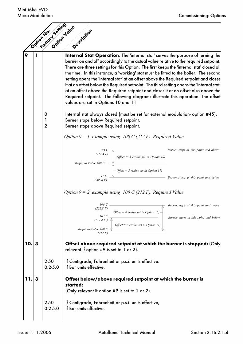
Micro Modulation
Issue: 1.11.2005 Autoflame Technical Manual Section
Mini Mk5 EVO
9 1 Internal Stat Operation: The 'internal stat' serves the purpose of turning theburner on and off accordingly to the actual value relative to the required setpoint.There are three settings for this Option. The first keeps the 'internal stat' closed allthe time. In this instance, a 'working' stat must be fitted to the boiler. The secondsetting opens the 'internal stat' at an offset above the Required setpoint and closesit at an offset below the Required setpoint. The third setting opens the 'internal stat'at an offset above the Required setpoint and closes it at an offset also above theRequired setpoint. The following diagrams illustrate this operation. The offsetvalues are set in Options 10 and 11.
0 Internal stat always closed (must be set for external modulation- option #45).1 Burner stops below Required setpoint.2 Burner stops above Required setpoint.
10. 3 Offset above required setpoint at which the burner is stopped: (Onlyrelevant if option #9 is set to 1 or 2).
2-50 If Centigrade, Fahrenheit or p.s.i. units effective.0.2-5.0 If Bar units effective.
11. 3 Offset below/above required setpoint at which the burner isstarted:(Only relevant if option #9 is set to 1 or 2).
2-50 If Centigrade, Fahrenheit or p.s.i. units effective,0.2-5.0 If Bar units effective.
Option N
o.
Facto
ry Setti
ng
Option V
alue
Descrip
tion
2.16.2.1.4
Commissioning: Options
Offset = 3 (value set in Option 11)
Option 9 = 2, example using 100 C (212 F). Required Value.
Option 9 = 1, example using 100 C (212 F). Required Value.
Burner stops at this point and above
Required Value 100 C
97 C(206.6 F)
103 C(217.4 F)
Burner starts at this point and below
Required Value 100 C(212 F)
103 C(217.4 F )
106 C(222.8 F)
Burner starts at this point and below
Burner stops at this point and above
Offset = 6 (value set in Option 10)
Offset = 3 (value set in Option 11)
Offset = 3 (value set in Option 10)
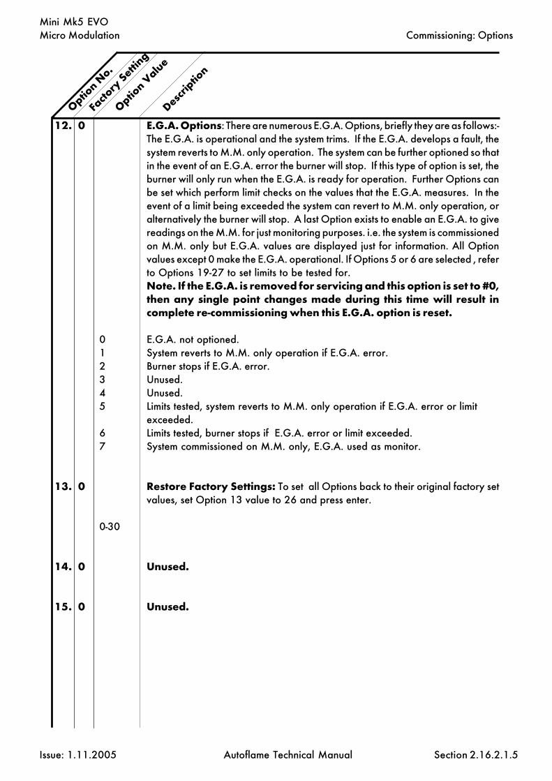
Micro Modulation
Issue: 1.11.2005 Autoflame Technical Manual Section
Mini Mk5 EVO
12. 0 E.G.A. Options: There are numerous E.G.A. Options, briefly they are as follows:-The E.G.A. is operational and the system trims. If the E.G.A. develops a fault, thesystem reverts to M.M. only operation. The system can be further optioned so thatin the event of an E.G.A. error the burner will stop. If this type of option is set, theburner will only run when the E.G.A. is ready for operation. Further Options canbe set which perform limit checks on the values that the E.G.A. measures. In theevent of a limit being exceeded the system can revert to M.M. only operation, oralternatively the burner will stop. A last Option exists to enable an E.G.A. to givereadings on the M.M. for just monitoring purposes. i.e. the system is commissionedon M.M. only but E.G.A. values are displayed just for information. All Optionvalues except 0 make the E.G.A. operational. If Options 5 or 6 are selected , referto Options 19-27 to set limits to be tested for.Note. If the E.G.A. is removed for servicing and this option is set to #0,then any single point changes made during this time will result incomplete re-commissioning when this E.G.A. option is reset.
0 E.G.A. not optioned.1 System reverts to M.M. only operation if E.G.A. error.2 Burner stops if E.G.A. error.3 Unused.4 Unused.5 Limits tested, system reverts to M.M. only operation if E.G.A. error or limit
exceeded.6 Limits tested, burner stops if E.G.A. error or limit exceeded.7 System commissioned on M.M. only, E.G.A. used as monitor.
13. 0 Restore Factory Settings: To set all Options back to their original factory setvalues, set Option 13 value to 26 and press enter.
0-30
14. 0 Unused.
15. 0 Unused.
Option N
o.
Facto
ry Setti
ng
Option V
alue
Descrip
tion
2.16.2.1.5
Commissioning: Options

Micro Modulation
Issue: 1.11.2005 Autoflame Technical Manual Section
Mini Mk5 EVO
16. 0 Sequencing/DTI: If Option 16 is set to values 1 or 3, then this M.M. will respondto sequencing commands (see section on Sequencing). A lead boiler can beselected by pressing the LEAD BOILER pushbutton on the front facia of theappropriate M.M. when in the ‘IBS’ screen. Only 1 M.M. may be selected as leadboiler at a time or the sequencing will not operate. The lead boiler can also beselected via the D.T.I., but the ‘LEAD BOILER’ pushbutton overrides the DTI leadboiler selection.
0 No sequencing.1 Sequencing enabled.2 Setpoint & enable/disable commands accepted from D.T.I.3 Both of 1 & 2.
17. 0 NO & CO displayed when running on oil: If fuel 2 is selected, then thedisplaying of CO & NO can be on or off. This Option is only relevant if an E.G.A.is operational on the system.
0 NO & CO not displayed.1 NO & CO is displayed normally.
18. 1 Carry forward of Trim: When the system modulates, the correction that maybe existing on the air damper position can be carried forward. Only air pluscorrection is carried forward. This Option is only relevant if an E.G.A. isoperational on the system.
0 No carry forward of trim.1 Trim carried forward.
19. 0 Upper offset limit % O2.E.G.A. Limits: Options 19-27 are only relevant if an E.G.A. is operational on thesystem. Option 12 value 5 or 6 must be selected if any of the following limit checksare to be invoked. To enable the checking of a particular limit, make the value ofthe appropriate Option a non-zero value. The amount of 'limit offset' is specifiedby the value entered. e.g. If the 'upper limit offset O2' is to be enabled and the valueof the offset is 2.0%, then enter the value of 2.0 for Option No. 19.
0-10.0 % O2.
20. 0 Upper offset limit % CO2.0-10.0 % CO2
21. 0 Upper offset limit CO.0-2000 CO
22. 0 Lower offset limit % O20-10.0 % O2
Option N
o.
Facto
ry Setti
ng
Option V
alue
Descrip
tion
2.16.2.1.6
Commissioning: Options

Micro Modulation
Issue: 1.11.2005 Autoflame Technical Manual Section
Mini Mk5 EVO
23. 0 Lower offset limit % CO20-10.0 % CO2
24. Unused.
25. 0 Absolute value % O2 . (System checks for O2 values lower than value specifiedin this Option).
0-20.0 % O2
26. 0 Absolute value % CO2. (System checks for CO2 values higher than valuespecified in this Option).
0-20.0 % CO2
27. 0 Absolute value ppm CO. (System checks for CO readings higher than valuesspecified in this Option).
0-2000 CO ppm
28. 20 Trim threshold: This option is only relevant if an E.G.A. is operational on thesystem. The value set in this Option is subtracted from the operator set "Required"value. If the Actual value is less than the result then no Trim action will be effected.If the trim is to be effective all the time then set the value to zero. Must also be setto O for the E.G.A. to operate when external modulation is optioned.
0-50 If Centigrade, Fahrenheit or p.s.i. units effective.0-5.0 If Bar units effective.
29. 1 Golden Start: NB. Must be entered on each fuel individually if more than onefuel is commissioned. Refer to section 2.14.12 for further details.
0 Golden Start operates.1 Golden Start does not operate.
30. 50 D.T.I. - Required Value Minimum Limit: If the system is being used with a D.T.I.a maximum and minimum limit for the Required value must be set. The M.M. willonly act on values within the limits set. If a value is received from the D.T.I., thatis outside these limits, it will be ignored and the system uses its previous Requiredvalue. Practical range is limited to range of sensor selected.
5-995 If Centigrade, Fahrenheit or p.s.i. units effective.0.5-99.5 If Bar units effective.
31. 100 Maximum Limit.
5-995 If Centigrade, Fahrenheit or p.s.i. units effective.0.5-99.5 If Bar units effective.
Option N
o.
Facto
ry Setti
ng
Option V
alue
Descrip
tion
2.16.2.1.7
Commissioning: Options

Micro Modulation
Issue: 1.11.2005 Autoflame Technical Manual Section
Mini Mk5 EVO
32. 20 Trim Delay: After ignition the sampling system does not sample for the periodof time set in this option. (Only relevant if E.G.A. is operational on system). Thisallows for the boiler to warm up and combustion to stabilise before samplingcommences.
0-250 Period (seconds) after ignition no sampling takes place.
33. 1 M.M. Identification No. - Sequencing Options: If this M.M. is configured aspart of a sequencing system and/or required to communicate with a D.T.I. then thefollowing three options must be set: The first is an identification number for thisM.M.. The second is the rating of the burner, and the third is the "sequencing scantime". Refer to Sequencing Section for further explanation.
1-10 Identification Number.
34. 5 Rating of burner
1-999 See option 77 for units.
35. 10 Sequence Scan Time. (minutes)
1-100 Sequence Scan time (Minutes).
36. 0 E.G.A. Sensor Selection: Available when using an E.G.A. System fitted withNO/SO2sensors. The following option is for selecting the type of Sensor required:Part No. EGA20005 for NO; EGA20008 for SO2.
SO2 NO0 Off Off1 Off On2 On Off3 On On
37. 0 Time Between ReadingsExplanation of D. (Derivative Action): The user adjustable control variablesto set up the D action are as detailed below. (Derivative is equivalent to 'Rate')
0 (0=off)1-200 Seconds. The time interval between the controller comparing Actual and Required
Setpoint values.
38. 2 Deadband. The Deadband is the margin above and below the Setpoint withinwhich no derivative control action occurs.
0-15 If Centigrade, Fahrenheit or PSI units optioned.0-1.5 If Bar units optioned.
Option N
o.
Facto
ry Setti
ng
Option V
alue
Descrip
tion
2.16.2.1.8
Commissioning: Options

Micro Modulation
Issue: 1.11.2005 Autoflame Technical Manual Section
Mini Mk5 EVO
39. 10 Response Sensitivity.1-100 %
The Sensitivity Number indicates the amount of percentage firing rate increaseor decrease that is inflicted by the Derivative action;
e.g. If the chosen value was 10% then 10% of the maximum firing rate would beadded to the existing rate of fire; i.e.: If the burner were firing at 50% load and thederivative action was triggered the firing rate would increase by 10+50 to 60%.
The following is an example of the above control philosophy in action:
Note: “Time Between Readings” set to 20 seconds.“Deadband” set to 2°C (2°F.)"Response Sensitivity” set to 10%.
Setpoint Information:“Required” set to 90°C (190°F.)“Actual” reads 86°C (186°F.)
Firing Rate Information:Burner firing at 50% of capacity.
In the example situation there has been 4°C (4°F) drop in temperature below the“Required” value. The Deadband is set at 2°C (2°F.), therefore the Derivativeaction will be triggered as the deviation from Setpoint is in excess of 2°C (2°F.).In this example 10% will be added to the 50% firing rate resulting in an increasein firing rate to 60% of capacity. The “Time Between Readings” is set for 20 seconds and if after this time intervalthe “Actual” reading is not within the 2°C (2°F) deviation from “Required”Deadband another 10% would be added to the 60% firing rate which would resultin a 70% firing rate.By careful selection of “Time Between Readings” “Deadband” and “ResponseSensitivity” an ideal response to rate of change over time can be configured.The control philosophy detailed operates inversely if the “Actual” temperatureexceeds the Setpoint and is outside the “Deadband”.To enable or switch on the Derivative action the “Time Between Readings” mustbe set in excess of 10 seconds.
40. 0 Unused
Option N
o.
Facto
ry Setti
ng
Option V
alue
Descrip
tion
2.16.2.1.9
Commissioning: Options

Micro Modulation
Issue: 1.11.2005 Autoflame Technical Manual Section
Mini Mk5 EVO
41. 0 Steam Boiler SequencingOptions 41, 42, 43 and 44 are related to the "Standby Warming" Sequencingstate. Option 42 enables an offset to be set relative to the Required value togenerate a "phantom setpoint". During this "Standby Warming" operation the‘internal stat’ operates on the phantom setpoint. Options 43 and 44 are offsetvalues above and below the phantom setpoint (i.e. Options 10 and 11 are notused for the phantom setpoint ‘internal stat’ offsets). When a boiler is set to the"Standby Warming" state, by the M.M. Sequencing commands, it runs for a periodof time at low flame and then off for a period. This action keeps the boiler warm.Option 53 sets the time interval that the burner is Off: Option 54 sets the time thatthe burner is On. If Option 41 = 0 only one boiler will be set to the "StandbyWarming" state. Boilers further down the sequence will be set to the "OFF" state.In this case Options 53 and 54 set the ON and OFF time. (If Options 41 and 53are 0 then Hot Water Sequencing is implemented).
0 3 State Steam Sequencing. ON, Standby/Warming , Off1 2 State Steam Sequencing. ON, Standby/Warming
42. 20 Phantom Setpoint. Offset below normal Required value.
0-100 If Centigrade, Fahrenheit or p.s.i. units effective.0-10.0 If Bar units effective.
43. 5 Offset above the phantom setpoint when the burner stops.2-50 If Centigrade, Fahrenheit or p.s.i. units effective.0.2-5.0 If Bar units effective.
44. 5 Offset below the phantom setpoint when the burner starts.2-50 If Centigrade, Fahrenheit or p.s.i. units effective.0.2-5.0 If Bar units effective.
45. 0 External Modulation: If this option is enabled, the usual P.I.D. control isdisabled and the percentage of firing is set by an external voltage applied to theappropriate input. 0 volts sets the firing rate to minumum, 10.0 volts sets the firingrate to maximum. The 10 point fuel flow metering curve must be entered forcorrect operation. See option #57.Option #9 must be set to zero for external modulation.
0 Disabled1 Enabled
46. Unused.
Option N
o.
Facto
ry Setti
ng
Option V
alue
Descrip
tion
2.16.2.1.10
Commissioning: Options
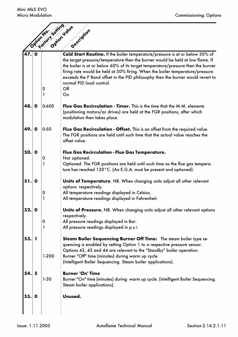
Micro Modulation
Issue: 1.11.2005 Autoflame Technical Manual Section
Mini Mk5 EVO
47. 0 Cold Start Routine. If the boiler temperature/pressure is at or below 30% ofthe target pressure/temperature then the burner would be held at low flame. Ifthe boiler is at or below 60% of its target temperature/pressure then the burnerfiring rate would be held at 50% firing. When the boiler temperature/pressureexceeds the P Band offset in the PID philosophy then the burner would revert tonormal PID load control.
0 Off1 On
48. 0 0-600 Flue Gas Recirculation - Timer. This is the time that the M.M. elements(positioning motors/ac drives) are held at the FGR positions, after whichmodulation then takes place.
49. 0 0-50 Flue Gas Recirculation - Offset. This is an offset from the required value.The FGR positions are held until such time that the actual value reaches theoffset value.
50. 0 Flue Gas Recirculation - Flue Gas Temperature.0 Not optioned.1 Optioned. The FGR positions are held until such time as the flue gas tempera-
ture has reached 120°C. (An E.G.A. must be present and optioned).
51. 0 Units of Temperature. NB. When changing units adjust all other relevantoptions respectively.
0 All temperature readings displayed in Celsius.1 All temperature readings displayed in Fahrenheit.
52. 0 Units of Pressure. NB. When changing units adjust all other relevant optionsrespectively.
0 All pressure readings displayed in Bar.1 All pressure readings displayed in p.s.i.
53. 1 Steam Boiler Sequencing Burner Off Time: The steam boiler type se-quencing is enabled by setting Option 1 to a respective pressure sensor.Options 42, 43 and 44 are relevant to the "Standby" boiler operation.
1-200 Burner "Off" time (minutes) during warm up cycle.(Intelligent Boiler Sequencing. Steam boiler applications).
54. 5 Burner 'On' Time1-30 Burner "On" time (minutes) during warm up cycle. (Intelligent Boiler Sequencing.
Steam boiler applications).
55. 0 Unused.
Option N
o.
Facto
ry Setti
ng
Option V
alue
Descrip
tion
2.16.2.1.11
Commissioning: Options

Micro Modulation
Issue: 1.11.2005 Autoflame Technical Manual Section
Mini Mk5 EVO
56. 1 Operation of Alarm Output, Terminal AL, NB this is a switchedneutral and not a voltage output terminal:
1 Relay normally Off, On when Alarm.2 Relay normally On, Off when alarm.
57. 0 Flow Metering: If the Air window shows 57 and the Required window shows1 when ENTER is pressed to store the Options, then the 10 point calibrationprocedure will be invoked the next time the burner starts.
0 No Flow Metering.1 Flow Metering Operates.2 Totalised Flow Metering reset to zero for fuel selected
58. Unused.
59. Unused.
60. 0 Hand/Auto Bumpless Transfer Operation.0 Fuel valve goes directly to last set Hand position.1 Hand position (taken on present fuel valve position when changing from Auto
to Hand operation).2 As 0, but Hand position is not stored in permanent memory.
61. 1 Flow metering units fuel 1 - Gaseous0 Cubic feet1 Cubic meters2-10 Unused
62. 3 Flow metering units fuel 2 - Liquid0 Unused1 Lbs.2 Kilograms3 Litres4 US gallons5-10 Unused
63. Unused.
64. Unused.
65. Unused.
66. Unused.
Option N
o.
Facto
ry Setti
ng
Option V
alue
Descrip
tion
2.16.2.1.12
Commissioning: Options

Micro Modulation
Issue: 1.11.2005 Autoflame Technical Manual Section
Mini Mk5 EVO
67. 1 Purge Position: The following Options tell the M.M. which channels are to beincluded in the Purge sequence. (See Option 5 for Purge Position).
0 Channel 1 to Purge position.1 Channel 1 to remain closed for Purge.
68. 0 Channel 2 Purge position.0 Channel 2 to Purge position.1 Channel 2 to remain closed for Purge.
69. 0 Channel 3 Purge position.0 Channel 3 to Purge position.1 Channel 3 to remain closed for Purge.
70. Unused.
71. 0 Fuel 1 - Fuel type.0 Natural gas
72. 1 Fuel 2 - Fuel type.1 Light Distillate Oil2 Heavy Fuel Oil
73. Unused.
74. Unused.
75. 0 Purge Motor Travel Speed: During a Purge Sequence the Motor Travel Speedcan be set independent of Option 2. This affects all selected channels.
0 -100 0 = Quickest time,100 = Slowest time.
76. 0 Unused.
77. 0 Burner Rating Units.Display purposes only for Flow Metering.0 KW x100 /hr1 Kg x100 /hr2 MW /hr3 Btu x100 /hr4 Hp x100 /hr5 lbs x100 /hr6 Btu x1000/hr7 Hp x10/hr8 lbs x1000/hr9 Btu x1000000/hr
Option N
o.
Facto
ry Setti
ng
Option V
alue
Descrip
tion
2.16.2.1.13
Commissioning: Options

Micro Modulation
Issue: 1.11.2005 Autoflame Technical Manual Section
Mini Mk5 EVO
78- Unused.85.
86. 0 Channel 1 Softened Error checking Select - increases positioning error fom0.1° to 0.5° for Industrial motor
0 CH1 normal positioning motor.1 CH1 industrial positioning motor/softened error checking.
87. 0 Channel 2 Softened Error checking Select .0 CH2 normal positioning motor.1 CH2 industrial positioning motor/softened error checking.
88. 0 Channel 3 Softened Error checking Select.0 CH3 normal positioning motor.1 CH3 industrial positioning motor/softened error checking.
89- Unused.109.
110. 1 Burner control.1 Non-permanent operation. Internal - Standard Scanner
111. 0 Pilot0 Interrupted pilot1 Intermittant pilot (expanding flame)
112. 40 Pre purge time5-100 Seconds/Minutes (check setting of option #135)
113. 3 Pre ignition time. Time ignition transformer is on before gas valve opens.3-5 Seconds
114. 3 First safety time. Time pilot valve is open before UV is checked.3-10 Seconds
115. 3 Pilot prove time. (Pilot trial for ignition PTFI)3-5 Seconds
116. 3 Fuel 1 Second safety time (Main trial for ignition MTFI).(Not Applicable to expanding flame - see option 111)
3-10 Seconds
117. 5 Main flame prove time.5-20 Seconds
Option N
o.
Facto
ry Setti
ng
Option V
alue
Descrip
tion
2.16.2.1.14
Commissioning: Options

Micro Modulation
Issue: 1.11.2005 Autoflame Technical Manual Section
Mini Mk5 EVO
118. 0 Post purge time0-100 Seconds (0 - No post purge). UV not checked during post purge.
119. 10 Control Box Recycle time. Time delay from burner shut down to startup.3-120 Second
120. 10 UV Threshold5-50 Minimum Flame Signal Strength during pilot. (At all other times the UV threshold
is fixed at 5).
121. 5 Delay from start of pre-purge after which air switch checked5-10 Seconds
122. 0 Flame Detection Method0 UV scanner1 Do not select2 Ionisation
123. 3 Fuel 2 Second safety time (Main trial for ignition MTFI).(Not Applicable to expanding flame - see option 111)
3-15 Seconds
124- Unused134
135 0 Change pre-purge time from seconds to minutes0 Seconds1 Minutes
136- Unused149
150. 0 Clear ALL Commissioning Data and restore Options/Parameters tofactory settings.
0 - 10 Range5 Clear Commissioning Data
FOR SAFETY REASONS OPTIONS 110 TO 150 ALSO HAVETO BE ENTERED IN AS PARAMETERS. IT IS THECOMMISSIONING ENGINEER'S RESPONSIBILITY TOENSURE ALL SETTINGS ARE IN ACCORDANCE WITH THEAPPROPRIATE STANDARDS.
Option N
o.
Facto
ry Setti
ng
Option V
alue
Descrip
tion
2.16.2.1.15
Commissioning: Options

Micro Modulation
Issue: 1.11.2005 Autoflame Technical Manual Section
Mini Mk5 EVO
2.16.2.2 Parameters
To Select Parameter Mode.Ch1, Ch2, Ch3 refer to the rows of buttons respectively starting with CH1 at the top.
Parameter values can be changed by entering the Parameter mode. The password must first be entered.To enter the password follow the steps listed.
Either deselect and then select fuel or power down and then up.
If system is already commissioned, press before the COM l.e.d. stops flashing.
If system is not already commissioned, commissioning mode will be set automatically.
The password screen is displayed.
Use the CH1 and CH2 buttons to set the Password codes. Then press the and
buttons simultaneously.
The parameters screen will then be displayed as below:
Rows 2, 3 & 4 display textual descriptions of the parameter number and value.
To change Parameter number use the CH2 buttons.
To change value use the CH3 buttons.
Any number of Parameter values can be changed when in Parameter mode.
When changes have been made press
All new Parameter values are then permanently stored.
Note: Parameters that are noted as unused must not be adjusted from their factorysettings.
COM
CLOSE
ENTER
MEMORY
Commissioning: Parameters
2.16.2.2.1
OPENLEADBOILER

Micro Modulation
Issue: 1.11.2005 Autoflame Technical Manual Section
Mini Mk5 EVO
1 3 0-20 Sequencing - Offset value when unit goes off linei.e. If the Standby Boiler fails to start the scan time will be decreased by 3 minutes.If the scan time is set to 10 minutes, this would be reduced to 7 minutes scan time.
2 1 1-10 Sequencing - Time between data requests (seconds). Bus driver request info everysecond, M.M's transmit every second, DTI only listens to Transmissions.
3 1 1-10 Sequencing - Number of boilers initially set on after powerdown.
4 45 5-100 E.G.A. -Seconds ENTER button disabled after E.G.A. pressed
5 4 1-50 Sequencing - Number of minutes, time out value to reach modulation, i.e. If theboiler is not modulating after being asked to contribute to load, it is taken out ofthe sequence loop. After being asked to modulate the burner must start tomodulate in 4 minutes.
6 60 5-100 Unused.
7 16 1-50 Unused.
8 30 5-240 E.G.A. - Delay after draining before trim cycle start ie. Wash out period, Whencells being cleaned with air, this value maintains the last readings until the airsampled during the drain period has gone.
9 60 5-240 E.G.A. - Auto commission time
10 0 Unused.
11 25 5-60 Air flush time during Auto Commission - (Seconds).
12 0 0-1 E.G.A. - CO included in trim calculation on F2 (See Option 17).0 - no1 - yesi.e Required when running gas on F2.
13 20 5-30 E.G.A. - ÷4 = % of Air damper. Amount of Autocommission trim. Applies to Air(-)only.
14 20 1-200 E.G.A. - ÷2 Number of degrees the fuel valve moves before negative trim is reset.
15 5 2-100 Number of seconds positioning motors are held at "choke" position. (Applies toGolden Start only, see option 29). This time starts from the ignition point.
16 12 1-50 Time between calibrations, (÷ 2 = Hours)Calibrates every 6 hours if burner does not turn off.
17 3 1-10 E.G.A. - Number of trims before error flagged when limits exceeded.(each Trim = 30 Seconds)
Param
eter N
o.
Facto
ry Setti
ng
Parameter V
alue
Descrip
tion
Commissioning and Setting up Procedure: Parameters
2.16.2.2.2
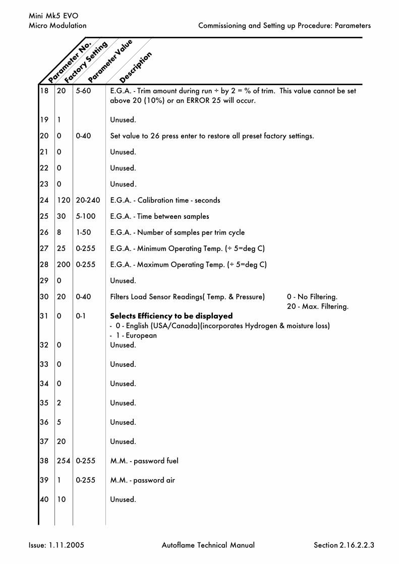
Micro Modulation
Issue: 1.11.2005 Autoflame Technical Manual Section
Mini Mk5 EVO
Parameter V
alue
18 20 5-60 E.G.A. - Trim amount during run ÷ by 2 = % of trim. This value cannot be setabove 20 (10%) or an ERROR 25 will occur.
19 1 Unused.
20 0 0-40 Set value to 26 press enter to restore all preset factory settings.
21 0 Unused.
22 0 Unused.
23 0 Unused.
24 120 20-240 E.G.A. - Calibration time - seconds
25 30 5-100 E.G.A. - Time between samples
26 8 1-50 E.G.A. - Number of samples per trim cycle
27 25 0-255 E.G.A. - Minimum Operating Temp. (÷ 5=deg C)
28 200 0-255 E.G.A. - Maximum Operating Temp. (÷ 5=deg C)
29 0 Unused.
30 20 0-40 Filters Load Sensor Readings( Temp. & Pressure) 0 - No Filtering.20 - Max. Filtering.
31 0 0-1 Selects Efficiency to be displayed- 0 - English (USA/Canada)(incorporates Hydrogen & moisture loss)- 1 - European
32 0 Unused.
33 0 Unused.
34 0 Unused.
35 2 Unused.
36 5 Unused.
37 20 Unused.
38 254 0-255 M.M. - password fuel
39 1 0-255 M.M. - password air
40 10 Unused.
Param
eter N
o.
Facto
ry Setti
ng
Descrip
tion
2.16.2.2.3
Commissioning and Setting up Procedure: Parameters

Micro Modulation
Issue: 1.11.2005 Autoflame Technical Manual Section
Mini Mk5 EVO
41 5 Unused.
42 4 Unused.
43 7 Unused.
44 0.4 0-4.0 E.G.A. - O2 window inside which no further trim takes place.
45 0.2 0-2.0 E.G.A. - CO2 window inside which no further trim takes place.
46 0 Unused.
47 0 Unused.
48 0 Unused.
49 0 0-1 Set to 1 if required setpoint not to be stored permanently in memory. This isimportant to set if changing the required setpoint often, e.g. through the DTI.
50 0 Unused.
51 0 Unused.
52 0 0-2 Number of decimal points (please see table below).
53 0 0-9990 Maximum value (please see table below).
54 0 0-100 0-10.0 volt. Maximum voltage (please see table below).
55 0 0-9990 Minimum value (please see table below).
56 0 0-100 0-10 volt. Minimum voltage (please see table below).The table below shows examples on how to set up the paramters when using anexternal load sensor.
Param
eter N
o.
Facto
ry Setti
ng
Descrip
tion
Parameter V
alue
2.16.2.2.4
Commissioning and Setting up Procedure: Parameters
Example 1: Pressure Application Example 2: Temperature ApplicationRequired/Actual Range- 0.0-100.0bar Required/Actual Range- 1000-2000FInput Signal- 0-10 Volts Input Signal- 1-6 Volts
Option 1- 11 Option 1- 10Option 52- pressure units Option 51- temperature unitsParameter 52- 1 Parameter 52- 0Parameter 53- 1000 Parameter 53- 2000Parameter 54- 10.0 Parameter 54- 6.0Parameter 55- 00 Parameter 55- 1000Parameter 56- 0.0 Parameter 56- 1.0

Micro Modulation
Issue: 1.11.2005 Autoflame Technical Manual Section
Mini Mk5 EVO
57 0 Unused.
58 0 Unused.
59 0 Unused
60 0 0 - 1 0 - Normal E.G.A. Operation1 - O2 Trim Interface Operation.
61 0 Unused.
62 0 Unused.
63 0 0 - 1 Set to 1. Leave for 2 seconds, then set back to 0 to clear lockout history.
64 0 0 - 1 Set to 1. Leave for 2 seconds, then set back to 0 to reset totalised fuel meteringvalues for all 4 fuels.
65 0 0 - 1 Set to 1. Leave for 2 seconds, then set back to 0 to reset burner history, hoursrun and number of start ups.
66 0 Unused.
67 0 Unused.
68 0 Unused.
69 0 0 - 1 0 - External Modulation input range 0-10V1 - External Modulation input range 2-10V
70 0 0 - 20 Filtering of Analogue input.1 - minimum20 - maximumThe value is the number of readings over which an average is taken, the smallerthe setting the quicker the response time.
71 0 0 - 1 Resolution of Analogue input.1 - fine20 - coarseThe effect of resolution is to filter noise on the input which causes hunting as theM.M. responds to a changing signal.
72 0 Unused.
73 0 Unused.
Param
eter N
o.
Facto
ry Setti
ng
Descrip
tion
Parameter V
alue
2.16.2.2.5
Commissioning and Setting up Procedure: Parameters

Micro Modulation
Issue: 1.11.2005 Autoflame Technical Manual Section
Mini Mk5 EVO
74 0 Unused.
75 0 Unused.
76 0 Unused.
77 0 Unused.
78 0 Unused.
79 0 Unused.
80 0 Unused.
81 0 Unused.
82 0 Unused.
83 0 Display Diagnostic values0 Disabled1 Enabled
84 0 Unused.
85 0 0-250 Modulation Exerciser. Repeatedly run between high and low flame. The higherthe value, the longer the high/start position is maintained.
86 0 0 - 99 IBS change down threshold. If left at 0 change down threshold = 85% firingrate.
87 0 0 - 99 IBS change up threshold. If left at 0 change up threshold = 95% firing rate.
NB: If Parameter 86 is set greater than 87 then they will default to 85% and95% respectively.
88 0 Unused.
89 0 Unused.
90 0 Flue Gas Recirculation0 Positions entered after commissioning.1 Positions entered during commissioning.
91 0 Unused.
Param
eter N
o.
Facto
ry Setti
ng
Descrip
tion
Parameter V
alue
2.16.2.2.6
Commissioning and Setting up Procedure: Parameters

Micro Modulation
Issue: 1.11.2005 Autoflame Technical Manual Section
Mini Mk5 EVO
92 0 Unused.
93 0 Unused.
94 0 Unused.
95 0 Unused.
96 0 Unused.
97 0 Unused.
98 0 Unused.
99 0 Unused.
100 0 Assured Low Fire Shut Off0 Not optional1 Burner modulates to low fire before turning off.
101 0 Unused.
102 0 Unused.
103 0 Unused.
104 0 Unused.
105 0 Unused.
106 0 Unused.
107 0 Unused.
108 0 Unused.
109 0 Unused.
NB. Parameters 110 to 150 are a repeat of theirrespective options. These values need to be enteredas both an option value and a parameter value forsafety reasons.
2.16.2.2.7
Param
eter N
o.
Facto
ry Setti
ng
Descrip
tion
Parameter V
alue
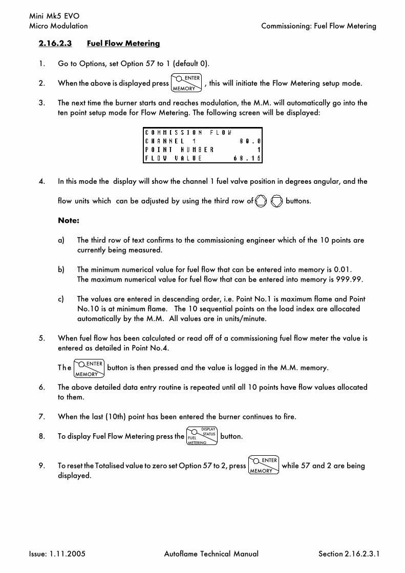
Micro Modulation
Issue: 1.11.2005 Autoflame Technical Manual Section
Mini Mk5 EVO
2.16.2.3 Fuel Flow Metering
1. Go to Options, set Option 57 to 1 (default 0).
2. When the above is displayed press , this will initiate the Flow Metering setup mode.
3. The next time the burner starts and reaches modulation, the M.M. will automatically go into theten point setup mode for Flow Metering. The following screen will be displayed:
4. In this mode the display will show the channel 1 fuel valve position in degrees angular, and the
flow units which can be adjusted by using the third row of buttons.
Note:
a) The third row of text confirms to the commissioning engineer which of the 10 points arecurrently being measured.
b) The minimum numerical value for fuel flow that can be entered into memory is 0.01.The maximum numerical value for fuel flow that can be entered into memory is 999.99.
c) The values are entered in descending order, i.e. Point No.1 is maximum flame and PointNo.10 is at minimum flame. The 10 sequential points on the load index are allocatedautomatically by the M.M. All values are in units/minute.
5. When fuel flow has been calculated or read off of a commissioning fuel flow meter the value isentered as detailed in Point No.4.
The button is then pressed and the value is logged in the M.M. memory.
6. The above detailed data entry routine is repeated until all 10 points have flow values allocatedto them.
7. When the last (10th) point has been entered the burner continues to fire.
8. To display Fuel Flow Metering press the button.
9. To reset the Totalised value to zero set Option 57 to 2, press while 57 and 2 are beingdisplayed.
Commissioning: Fuel Flow Metering
ENTER
MEMORY
ENTER
MEMORY
2.16.2.3.1
ENTER
MEMORY
DISPLAYSTATUS
FUELMETERING

Micro Modulation
Issue: 1.11.2005 Autoflame Technical Manual Section
Mini Mk5 EVO
2.16.3 End User Day to Day Operation
2.16.3.1 Normal Run Operation
Upon initial selection of a commissioned fuel, a logo screen flashes up followed by the 'M.M. STATUS'display. The COM l.e.d. flashes for five seconds.
To adjust the Required value press and use the third row accordingly.
The range of the required value is limited according to the type of sensor being used (See Option 1).
System information is displayed on numerous screens selectable by the following push buttons.
The respective l.e.d. will remain illuminated to indicate which mode is selected. The COM and E.G.A.modes are only selectable if an E.G.A. is optioned on the system.
In the event of the system being powered down the commissioning data, options and parameters, andthe required value are stored in the memory. During normal run operation the RUN led is on all thetime. When no fuels are selected only the RUN l.e.d. remains illuminated.
If an E.G.A. is operative on the system it will calibrate every time the burner starts and stops. WhenCOM or E.G.A. display modes are selected ‘Calibrating’ is displayed when the E.G.A. is calibrating.If the E.G.A. is cooling, COOL is displayed. If the burner is not firing, ‘E.G.A. Ready’ is displayed.When the burner is firing both modes show ‘Trim Threshold Low’, if the Actual value has not reachedthe value at which trimming is permitted. (See Option 28.) If an E.G.A. error has occurred the errorcode number is displayed if either of E.G.A. or COM modes are selected.
The software version number can be displayed by by pressing the Top CH1 buttons si-multaneously, when in the M.M. display mode.
End User Day to Day Operation
COM
2.16.3.1.1
FLAMESCANNER
RESETLOCKOUT
I.B.S.LEAD/LAG
121212 DISPLAY
STATUSFUELMETERING
M.M.
E.G.A.
DISPLAYSTATUS
FUELMETERING

Micro Modulation
Issue: 1.11.2005 Autoflame Technical Manual Section
Mini Mk5 EVO
Several different displays are available to provide the operator with information through start-up andnormal operation.
Selectable screens provide the following information:
2.16.3.1.2
End User Day to Day Operation
Startup/Fuel Select
Displayed at startup and when no fuel selected.
M.M. Status
Shows the angular value for each of the positioning motors,channels 1 to 3. The bottom row displays additional statusinformation, including Low Flame Hold, Hand Operation, GoldenStart, FGR Start.
IBS Status
For a multi boiler installation, this screen shows which is the leadboiler and the unit’s identification number.
E.G.A. On Line Values
When an Exhaust Gas Analyser (E.G.A.) is included in the sys-tem, this screen shows the actual values of the gases being meas-ured in the flue plus the exhaust gas temperature, ambient tem-perature, dT, and efficiency. A similar screen shows the commis-sioned values.
Burner Control Status/Time with UV scanner
Row 1 indicates the burner sequence state, row 2 gives the flamesignal strength- UV discharges. If the signal strength drops below5 then a lockout will occur.
Lockout History
Upto the last 16 lockouts are displayed here. Details include timeand date of lockout and reset, the cause of the lockout and atwhat stage of the sequence the lockout occured. Only one lockoutrecord can be displayed at a time. Press the flame scanner buttonto scroll through the records.
Fuel Metering Status
This screen displays which fuel is currently selected, the consump-tion at this point in time and the total fuel used to date.
System Status
This screen shows the present firing rate, which fuel is being used,and the required/actual values.
History
The hours run and the number of startups for the currently selectedfuel are displayed on this screen. The screen is selected by press-ing the display status button.
Burner Control Status/Time with Flame Rod
Row 1 indicates the burner sequence state, row 2 gives the flameionisation signal strength. If the signal strength drops below 5then a lockout will occur.

Micro Modulation
Issue: 1.11.2005 Autoflame Technical Manual Section
Mini Mk5 EVO
2.16.3.2.1
End User Day to Day Operation
2.16.3.2 Routine Adjustments
Setting Time & Date
To adjust the time and date settings go into COM mode. Power down the unit and restart. The
LED will be flashing and you have 5 seconds to press it. Then the password screen is
displayed. Set password to: , then press
'Set Clock' screen is displayed:
Use the buttons as detailed below to adjust the values appropriately.
Channel 1 Day
Channel 2 Date
Channel 3 Month
Year
Hours
Minutes
When finished press the flashing button to submit to memory.
Note: Hours are displayed in 24 hour mode.
Adjusting the Screen Contrast
Hold down any of the screen select buttons,
and then use the top row to adjust the contrast accordingly.
COM
1010
ENTER
MEMORY
CLOSE
CLOSE
COM I.B.S.LEAD/LAG
1212 DISPLAY
STATUSFUELMETERING
M.M.
E.G.A.
DISPLAYSTATUS
FUELMETERING
M.M.
E.G.A.
COM RUN
OPENLEADBOILER

Micro Modulation
Issue: 1.11.2005 Autoflame Technical Manual Section
Mini Mk5 EVO
Calibrating Actual Reading
A facility exists to adjust small errors in the actual value. Press to select display status
screen showing the actual value.
To increase the value press and the Ch3 simultaneously.
To decrease press and the CH3 .
RUN
RUN
2.16.3.2.2
End User Day to Day Operation
DISPLAYSTATUS
FUELMETERING

Micro Modulation
Issue: 1.11.2005 Autoflame Technical Manual Section
Mini Mk5 EVO
Low Flame Hold and Hand Operation
‘Low Flame Hold’ and ‘Hand’ operation are only effective when the burner is firing. They have no effectwhen the burner is off or during the burner start up cycle. They are effected by pressing the relevantpush buttons on the mini Mk5 evolution system when in the M.M. data screen (angular positions).
‘Low Flame Hold’ is brought into operation if the ‘low flame hold’ button is pressed. The minimum flameposition will be maintained from now on, until either the ‘Hand’ or ‘Auto’ buttons are pressed. LowFlame Hold will be established again by pressing the ‘low flame hold’ button. During ‘Low Flame Hold’the PID control is obviously ignored. When the system is held in the ‘Low Flame Hold’ position the LEDon the button will be illuminated.
‘Hand’ operation enables the fuel valve position to be set to a specific position, in the range of minimumto maximum flame. Once a position has been set it is recorded in the M.M. units memory. Each timethe burner starts the fuel valve will be positioned to the ‘hand’ position set previously, even if the M.M.unit has been powered down. The M.M. system sets the fuel valve to the hand position whenever the‘Hand’ button is pressed. Once the burner is firing in the ‘hand’ position the firing rate can be adjusted
by switching to the 'M.M.' screen and using the bottom row of buttons on the M.M. facia.
When the system is held in the ‘Hand’ position the LED on the button will be illuminated.
To place the M.M. unit in ‘Auto’ press the ‘Auto’ button and the M.M. unit will follow the PID control.The ‘Auto’ LED will be illuminated.
See Option #60 for details on Bumpless Transfer.
Lead Boiler Select
A lead boiler can be selected by pressing the LEAD BOILER push button on the front facia of theappropriate M.M. when in the ‘IBS’ screen. Only 1 M.M. may be selected as lead boiler at a timeor the sequencing will not operate. The lead boiler can also be selected via the D.T.I., but the LEADBOILER push button overrides the DTI lead boiler selection.
Note: The selections of Low Flame Hold/Hand Operation/Auto/Lead Boiler Select are non-volatile, i.e. their status is retained in the event of loss of power.
2.16.3.2.3 Hand/Auto/Low Flame Hold and Lead Boiler Select Facilities
Hand/Auto & Low Flame Hold Facilities
2.16.3.2.3

Micro Modulation
Issue: 1.11.2005 Autoflame Technical Manual Section
Mini Mk5 EVO
2.16.3.3.1
2.16.3.3 EPROM Version Numbers
To display the software version number select the M.M. Display screen, then press Channel 1 Upand Down simultaneously.

Micro Modulation
Issue: 1.11.2005 Autoflame Technical Manual Section
Mini Mk5 EVOOther Information and Illustrations
2.16.4 OTHER INFORMATION AND ILLUSTRATIONS
2.16.4.1 Mini Mk.5 EVO M.M. Facia
2.16.4.1

Micro Modulation
Issue: 1.11.2005 Autoflame Technical Manual Section
Mini Mk5 EVOOther Information and Illustrations
2.16.4.2 Mini Mk.5 EVO M.M. Enclosure Dimensions
2.16.4.2
COM
CLOSE
MEMORY
START
OPEN
HIGH
INTER
ENTER
RUN
LEAD/LAG
FLAMESCANNER
RESETLOCKOUT
I.B.S.
Combustion Management Systems
MINI Mk.5 EVO System Pt. No. MMM5002E
Designed & Manufactured By
HAND
AUTO
BOILERLEAD
FLAME HOLDLOW
E.G.A.
M.M
DISPLAY
METERINGFUEL
STATUS
134.
00
163.00
MINI MK5 EVOLUTION OUTSIDEDIMENSIONS / CUT OUT DETAILS
PANEL CUT OUT DIMENSION
75.5
0
170.00
141.
00
135.
50
62.5
0

Micro Modulation
Issue: 1.11.2005 Autoflame Technical Manual Section
Mini Mk5 EVO
2.16.4.3 Schematic Connection Diagram
2.16.4.3
Other Information and Illustrations
UV
-
UV
+
ION
S BOO
APS
CPI
CFH
BM PFV
MFV
IG L PMP
C1U
C1D
C2U
C2D
C3U
C3D
2PV
AL
F1 F2E N
D-
D+ W3
BS-
BSS
BS+
S 0V 12V
SE+E- W1
W2
S
SERVO MOTORS
*NOTE:FOR 120v, TERMINAL PMP FEEDS POSITIONING MOTORS VIAA 120-24v TRANSFORMER AS SHOWN IN DOTTEDLINES.
5A FUSE
120Vac
LIV
E/H
OT
NEU
TRA
L
EART
H/G
ROU
ND
CC
WL
CH
1C
W
L/O
, MM
& E
GA
ALA
RM O
UTP
UT
I.B.S
. 2-P
ORT
VA
LVE
24Vac
CC
W
CC
W
L L
CH
2
CH
3
CW
CW
LN
LN
FUEL
2
FUEL
1
IGN
ITIO
N T
RAN
SFO
RMER
CA
LL F
OR
HEA
T
AIR
PRO
VIN
G S
WIT
CH
STA
RT/P
ILO
T FU
EL V
ALV
ES
MA
IN F
UEL
VA
LVES
BURN
ER M
OTO
R
BURN
ER O
N/O
FFLI
MIT
STA
T
120
230VOLTAGESELECTOR
FUSE FUSE
DC FUSEF1
E.G.A. RS485
DTI/IBS RS485
STEAM PRESSURESENSOR
FUEL SERVOCH1
AUX. SERVOCH3
AIR SERVOCH2
TEMP. SENSOR
FLAME ROD
UV DETECTOR
PRO
OF
OF
CLO
SURE
/ C
PI
120V/220V LIVE/HOTNEUTRAL
FUEL
SEL
ECT
SWIT
CH
OR
F2
MINI Mk.5 EVOLUTION (MMM5002E)SCHEMATIC CONNECTION DIAGRAM
DC FUSE
BLU
E
GRE
EN
RED
RED
WHITE
+V
W
0V
+V
W
0V
+V
W
0V
D-
D+
23
31
FOR SUPPLY CONNECTIONS USE WIRES
USE COPPER CONDUCTORS ONLYSUITABLE FOR AT LEAST 75° C
1 A T
0.315 A T
2 A T5 A T
51
50
BLU
E
RED
BLU
E
BLU
E
RED
RED

Micro Modulation
Issue: 1.11.2005 Autoflame Technical Manual Section
Mini Mk5 EVO
2.16.4.4 Mini Mk.5 Evolution Specifications
2.16.4.4.1 Classifications
Classification According to EN298 - F B L L J B
Mains Supply: 230V, +10%/-15% 120V, +10%/-15%
Environment: Temperature 0 to +600C (32 to 1400F)Humidity 0 to 90% non-condensing.
Protection Rating: The unit is designed to be panel mounted in any orientation and the front faciais IP65. The back of the unit is IP20.
Output Ratings:
230V Unit: MaxOutputs Terminal CFH 250 mA Must be connected through contactor
BM 250 mA Must be connected through contactorPFV 1Amp, 0.6 power factorMFV 1Amp, 0.6 power factorIG 1Amp, 0.6 power factor2PV 100mA To drive relay only - switched neutralAL 100mA To drive relay/lamp only - switched neutral
120V Unit:Outputs Terminal CFH 250 mA Must be connected through contactor
BM 250 mA Must be connected through contactorPFV 2Amp, 0.6 power factorMFV 2Amp, 0.6 power factorIG 2Amp, 0.6 power factor2PV 100mA To drive relay only - switched neutralAL 100mA To drive relay/lamp only - switched neutral
Note.
1. The Low voltage connections are not safe to touch. Protection against electric shock is provided bycorrect installation.2. Cabling should be a maximum 10m.3. Use screened cable as specified in Section 2.14.2.9.4.4. The burner 'High Limit Stat' must be of the manual reset type.5. When the system is running at 230V, the supply voltage at which the valve outputs are de-energisedis nominally 143V.
Other Information and Illustrations
2.16.4.4
47.5 - 63 Hz, Unit max. power consumption 10W
Tota
l Max
.Lo
ad 3
.5 A
mp.
Tota
l Max
.Lo
ad 5
Am
p.

Micro Modulation
Issue: 1.11.2005 Autoflame Technical Manual Section
Mini Mk5 EVO
2.16.4.5.1
Other Information and Illustrations
2.16.4.5 Mini Mk.5 Evolution Electrical Specifications
2.16.4.5.1 Low voltage terminals
E-, E+ Communications port connections to an Exhaust Gas Analyser.
D-, D+ Communications port connections for DTI and/or IBS/lead-lag operation.
BS-, BSS Connections to an Autoflame Boiler temperature detector.
BS-, BSS, BS+ Connections to an Autoflame Boiler pressure detector.
0V 0V Supply to Channel 1 and Channel 2 positioning motors.
12V +12V Supply to Channel 1 and Channel 2 positioning motors.
W1 Signal from Channel 1 positioning motor, indicating position.
W2 Signal from Channel 2 positioning motor, indicating position.
W3 Signal from Channel 3 positioning motor, indicating position.
BS- 0V Supply to Channel 3 positioning motor.
BS+ +12V Supply to Channel 3 positioning motor.
2.16.4.5.2 UV and ionisation terminals
UV-, UV+ Connections to an Autoflame UV sensor.
ION Connection to flame rod/ionisation probe.

Micro Modulation
Issue: 1.11.2005 Autoflame Technical Manual Section
Mini Mk5 EVO
2.16.4.5.3 Mains voltage terminals
BOO Mains voltage input. Burner on/off signal. Running interlock circuit.
APS Mains voltage input. Safety circuits (eg Air proving).
CPI Mains voltage input. Proving circuits (eg Gas valve proof of closure)
CFH Mains voltage output. Call for heat.
BM Mains voltage output. Burner motor.
PFV Mains voltage output. Start/Pilot valve.
MFV Mains voltage output. Main fuel valves.
IG Mains voltage output. Ignition transformer.
E Mains supply earth.
N Main supply neutral.
L Mains supply live/hot.
PMP Mains voltage output. Positioning motor power.
C1U Switched neutral – drives Channel 1 positioning motor clockwise.
C1D Switched neutral – drives Channel 1 positioning motor counter clockwise.
C2U Switched neutral – drives Channel 2 positioning motor clockwise.
C2D Switched neutral – drives Channel 2 positioning motor counter clockwise.
C3U Switched neutral – drives Channel 3 positioning motor clockwise.
C3D Switched neutral – drives Channel 3 positioning motor counter clockwise.
2PV Switched neutral – to drive 2-port valve for IBS operation.
AL Switched neutral - Alarm output for lockout/error/E.G.A. error.
F1 Mains voltage input. Selects fuel 1 curve.
F2 Mains voltage input. Selects fuel 2 curve.
S All terminals marked S are internally connected to the mains earth/groundterminal E. They are provided for connections to the various screened cables.Refer to the schematic connection diagrams, eg section 2.16.4.3.
Other Information and Illustrations
2.16.4.5.3

Micro Modulation
Issue: 1.11.2005 Autoflame Technical Manual Section
Mini Mk5 EVO
2.16.4.4 External Modulation
2.16.4.6
Other Information and Illustrations
D-
D+ W3
BS-
BSS
BS+
S 0V 12V
SE+E- W1
W2
S
To use external modulation it is required to use a 0-10V input on the terminals as detailed above. Itis not possible to use a steam pressure detector or temperature sensor when using externalmodulation. A ‘working stat’ must be fitted on the boiler. See option #45. Option #9 must be setto zero for external modulation.
Important note:It is necessary to use a signal isolator to prevent any excessive voltages being applied to theseterminals. The signal isolator used must have the following charcteristics:
Signal isolation voltage- 3.75kVCreepage- 5mmClearance- 4mmThe equipment and cables must be housed in a clean environment- IP55

E.G.A. Exhaust Gas Analysis
Issue: 1.11.2005 Autoflame Technical Manual Section
Section 3: E.G.A. Exhaust Gas Analysis
3: Index
3.1 Introduction
3.1.1 Features and Benefits3.1.2 Overview of System Operation3.1.3 An inside view3.1.3.1 An inside view Schematic
3.2 Sensor Characteristics
3.2.1 O2 Sensor3.2.2 CO, NO and SO2 Sensors3.2.3 CO2 Sensor
3.3 Commissioning and Setting up Procedures
3.3.1 Introduction3.3.2 Programming of Fuel/Air Positions3.3.3 Combustion Trim Operation3.3.4 Trim Timing Operation3.3.5 Graphical Trim Operation3.3.6 Efficiency Calculation
3.4 Error Checking, Self Diagnostics
3.4.1 Keys to Errors Detected3.4.2 LED Status Indication
3.5 End user Day to Day Operation
3.5.1 Normal run Operation
3.6 Electrical Schematics Showing all Terminal Interconnections
3.6.1 Interconnections Between M.M and EGA Mk63.6.2 Interconnections Between MM, EGA and DTI
3.7 Test and Calibration
3.7.1 Approach to Testing & Calibrating on EGA Mk.6
3.8 EGA Local Display
123456789012345678901234123456789012345678901234123456789012345678901234123456789012345678901234123456789012345678901234123456789012345678901234123456789012345678901234123456789012345678901234123456789012345678901234123456789012345678901234123456789012345678901234123456789012345678901234

E.G.A. Exhaust Gas Analysis
Issue: 1.11.2005 Autoflame Technical Manual Section
Section 3: E.G.A. Exhaust Gas Analysis.
3.9 EGA Setup Software Introduction
Using the Software (EGATOPC)
3.9.1 Calibrate Sensor (Replacing a Sensor)3.9.2 Status3.9.3 Options3.9.3.1 4-20mA outputs3.9.3.2 EGA Operating Mode3.9.3.3 Pinch Valve Control3.9.3.4 System Configuration3.9.3.5 Test & Calibration Menu3.9.3.6 Return to Main Menu3.9.3.7 Quit
3.10 Limits on Five Measured Combustion Parameters:- O2, CO2, CO, NOand Exhaust Gas Temperature
3.10.1 Overview of System Operation Features & Benefits3.10.2 Example of Limits for O2
3.10.3 Example of Limits for CO2
3.10.4 Example of Limits for CO
3.11 EGA Dimensions & Fixing Details
3.12 Standard EGA Sampling Probe
3.12.1 Installation and Maintenance3.12.2 EGA Sampling Probe Assembly3.12.3 EGA Sampling Probe Assembled3.12.4 Maintenance of Sampling Probe3.12.5 Installation Precautions3.12.6 Servicing the Sampling Probe
3.13 Internal Tubing Diagram
3.14 EGA with Bubble Filter
3.15 High Temperature Probes
3.16 Shipping the EGA
3: Index
1234567890123456789012345612345678901234567890123456123456789012345678901234561234567890123456789012345612345678901234567890123456123456789012345678901234561234567890123456789012345612345678901234567890123456123456789012345678901234561234567890123456789012345612345678901234567890123456
1

E.G.A. Exhaust Gas Analysis
Issue: 1.11.2005 Autoflame Technical Manual Section
3.1 Introduction
3.1.1 Features and Benefits
The E.G.A. Mk.6 is the accomplishment of ten years on-going research and development for the exhaustgas sampling system. The E.G.A. can be used for two separate applications:
Application No.1: E.G.A. stand alone
Stand alone sampling system. The emissions levels can be accessed via:
The local display on the front of the E.G.A. facia (serial numbers 5000+)The remote display pod, local to the installation (max. distance 15m)- older E.G.A. unitsThe 6 channel 4-20mA signals, user configurable (max. load 250 Ohms each)The Data Transfer Interface module (D.T.I.); this enables connection to a PC, BMS, PLC, e.t.c.
Application No.2: E.G.A. combustion trim
Interfaced with the Micro Modulation (M.M.) system enabling combustion trim. The combustion/emissionslevels can be accessed via:
The M.M. unit. This displays both the commissioned values and the actual valuesThe 6 channel 4-20mA signals, user configurableFrom the M.M. unit via the Data Transfer Interface module (D.T.I.); this enable connecttion to a PC, BMS,PLC, e.t.c.
Monitoring Capabilities.
O2 Oxygen % by volumeCO Carbon Monoxide ppmCO2 Carbon Dioxide % by volumeNO Nitrogen Oxide ppmSO2 Sulphur Dioxide ppm ORNO2 Nitrogen Dioxide ppmCombustion Efficiency % (a calculation of CO2 and temperature)Exhaust gas temperature Degrees Celsius or FahrenheitAmbient temperature Degrees Celsius or FahrenheitDelta temperature Degrees Celsius or Fahrenheit
NO and SO2 or NO2 are monitored only, not used for combustion trim.
3.1.1
Introduction

E.G.A. Exhaust Gas Analysis
Issue: 1.11.2005 Autoflame Technical Manual Section
3.1.2 Overview of system operation
The analyser samples the combustion gas via the stack mounted sampling probe (part #MM10003)purchased separately from the analyser. The exhaust gas is drawn from the stack by a pump mountedinternally within the analyser. Ensure that the supplied sample tubing is used between the samplingprobe and the analyser. The internal diameter of the sample tubing is 2mm; if a larger diameter tubingis used the sample gas remains resident in the tubing for a longer period. This will seriously effect thecorrect operation of the combustion trim.
Once the exhaust gas has entered the analyser the gas is reduced in temperature by the chiller block.The chiller block serves two functions; firstly reducing the gas temperature and secondly removing thecondensation from the gas prior to the gas entering the sensors. The condensate accumulated in thechiller unit is drained every 4.5 minutes automatically through the drain solenoid.
The exhaust gas is then filtered through the dry filter. This is a fine filter which removes any dust particlescarried over from the cooling process. On leaving the filter the exhaust gas is checked to ensure avacuum is maintained prior to entering the pump. On exiting the pump the exhaust gas is again checkedto ensure the pump is producing a pressure. Both pressure switches indicate there operation by the statusindication L.E.D.s. (located next to each pressure switch).
The conditioning process of the exhaust gas is now complete. The gases are now measured by thesensors. The exhaust gas now exits the sampling system from the clear tubing located at the rear of thechiller unit.
Important note:
The exhaust gas is vented into the air steam exiting the E.G.A. unit. This is located on the outside of theE.G.A. box next to the drain solenoid outlet. It is extremely important that the exhaust gas is vented toatmosphere, i.e. do not install the E.G.A unit within a sealed enclosure. This would cause the E.G.A.unit to self calibrate on contaminated gas. The E.G.A. unit will self calibrate every 6 hours or when theburner starts and stops.
3.1.2
Introduction

E.G.A. Exhaust Gas Analysis
Issue: 1.11.2005 Autoflame Technical Manual Section
Thermocouple I/P
Sample In FromE.G.A. Probe
Sample InletPinch Valve
NO Cell
CO/NO BypassPinch Valve
Pump
Data Port& 4-20mA
Outputs
PressureSwitch
FanVacuumSwitch
DrainSolenoid
MainsInput
Filter
ChillerBlock
L.E.D.Bank
(See Note)
Green O.K.Red Fault
PC Output(Via Lead)
Pt.No. DTI20018)
O² Cell
SO² Pump
CO² Cell
SO² or NO²Cell
SO²Pinch Valve
CO Cell
Note:
Green #1 = O.K.Red #2 = Fault or ServiceYellow #3 to 8 = Service Period Indicators (1 LED extinguishes every 2 Months)
Mains Supply = 230V/110V Standard
3.1.3 E.G.A. Mk.6 an Inside View (cover removed)
3.1.3
Introduction

E.G.A. Exhaust Gas Analysis
Issue: 1.11.2005 Autoflame Technical Manual Section
3.1.3.1 E.G.A. Mk.6 an Inside View (cover removed)
3.1.3.1
Introduction

E.G.A. Exhaust Gas Analysis
Issue: 1.11.2005 Autoflame Technical Manual Section 3.2.1
3.2 Sensor Characteristics
3.2.1 O2 Sensor
This is a newly developed electrochemical cell used for the detection of oxygen covering a concentration rangeof 0 to 100%. Due to the construction of the sensor they offer a long life and a high resistance when used withhigh sulphur content fuels. It is therefore suited to analysis when firing heavy or light fuel oil. The cell employsthe principles detailed below:-
The oxygen sensor incorporates a lead oxygen cell with a lead anode and a gold cathode, using a specific acidelectrolyte. Oxygen molecules which diffuse through a non porous Teflon membrane into the electrochemicalcell are reduced at the gold electrode. The current flow between the electrodes is proportional to the oxygenconcentration in the flue gases measured.
Features:
Virtually no influence from CO, H2, S, NOx, SOx and H2, i.e. no cross sensitivity.No warm up time required.
Operation ranges:
Detection range 0-20.9% O2
Accuracy ± 0.3%Operating temperature 5°C to 40°C (41°F to 104°F)Shelf life 6 months from date of dispatch(In normal operation the sensor has a life expectancy of 2 years & is guaranteed for 1 year)Long Term Output Drift < 1% signal/month typically.
< 10% over operating life.
Retaining Band
Sensor Characteristics

E.G.A. Exhaust Gas Analysis
Issue: 1.11.2005 Autoflame Technical Manual Section 3.2.2
3.2.2 CO ,NO and SO2 Sensors
These sensors are electrochemical cells which are specifically managed by the calibration philosophy within theE.G.A. unit. The accuracy of these sensors are within ±5% at 100ppm. From our experience over the last fiveyears we would expect to see a drift of ± 10ppm per annum without calibration. In our view this drift wouldnot be detrimental to the operation or application of the E.G.A. The life of the sensors is a function of theconcentration of gases measured over time. In order to optimize the life of the CO cell, the electronics will detectwhen the signal level from the cell reaches or exceeds 600ppm and will isolate the CO & NO cells. The gas flowto these cells is restored once the O2 & CO2 readings are restored to a level within the pre-programmed limits.
CO Measurement:On Gas Fuel Measuring Range 0-1000ppmOn Fuel Oil Optional, CO is not normally measured as standardResolution at 20 deg C 1ppmRepeatability 1% of signalShelf life 6 months from date of dispatch
NO Measurement:On Gas Fuel Measuring Range 0-1000ppmOn Fuel Oil Optional, NO is not normally measured as standardResolution at 20 deg C 1ppmRepeatability 2% of signalShelf life 6 months from date of dispatch
SO2 Measurement:On Gas Fuel Optional, SO2 is not normally measured as standardOn Fuel Oil Measuring Range 0-1000ppmResolution at 20 deg C 1ppmRepeatability 1% of signalShelf life 6 months from date of dispatch
Sensor Characteristics
Retaining Screws, Remove whenreplacing Sensor
Input Tube

E.G.A. Exhaust Gas Analysis
Issue: 1.11.2005 Autoflame Technical Manual Section 3.2.3
Retaining Band
3.2.3 CO2 Sensor
This is manufactured to an Autoflame specification and the technology employed is thermal conductiv-ity. This sensor has no moving parts and is not an electrochemical cell. The exact description of howthis works is commercially sensitive. The accuracy is ±0.3% of reading. The cross sensitivity is virtuallyzero to other gases due to the method of calibration used within the E.G.A. unit. The lifetime is not lessthan two years on gas firing, and on oil firing is dependent on the sulphur content of the fuel.
Measuring Range 0-20%Shelf life 12 months from date of dispatch
Sensor Characteristics

E.G.A. Exhaust Gas Analysis
Issue: 1.11.2005 Autoflame Technical Manual Section
3.3 Commissioning and Setting up Procedures
3.3.1 Introduction
Commissioning with the E.G.A. is an extension to commissioning with the M.M. The operator must be completelyfamiliar with the commissioning of the M.M. unit before commissioning with the E.G.A. module. Section #2 ofthe Technical manual clearly explains commissioning with the M.M. unit.
The commissioning procedure as described must be strictly adhered to. Anybody commissioning an M.M./E.G.A. system must have an adequate understanding of combustion plant and be officially certified by AutoflameEngineering or their registered Distributors. In the wrong hands, hazardous conditions could be made to exist.
The fundamental idea of the system is to set a fuel valve position and then set a corresponding air valve position.Care must be taken when adjusting the fuel and air positions so as not to create any unstable combustionconditions, e.g. moving the fuel valve to the open position without increasing the air valve correspondingly.
If the system being commissioned is an M.M. without an E.G.A. then a combustion monitor is required to checkthe exhaust gases. If the system does have an E.G.A. then a combustion monitor should not be necessary as theE.G.A. performs all normal exhaust gas measurements. When burning oil a smoke detection device is necessaryto check smoke generated is within government guide lines.
Ideally, to implement commissioning as quickly as possible arrange for a substantial load on the boiler. Thecommissioning procedure can be interrupted due to excess temperature or pressure, causing the burner to turnoff. In these instances the commissioning data accumulated so far is not lost. When the burner is called backon, the system starts up automatically and commissioning can proceed from where it left off.
Once the burner has been fired the maximum fuel position is entered first then descending fuel positions areentered consecutively until finally a minimum fuel position is entered. The CH1 and CH2 positions must alwaysbe less than he ones previously entered. However with CH3 - CH6 it is possible to move the position above orbelow the previously entered points.
On a newly installed system the following procedures should be carried out as listed:
1. Check all interconnecting wiring between the M.M. and external components are correct.2. Set the options required (refer to option section #2.14.2.4).3. Set up positioning motors.4. Programme fuel/air positions.
3.3.1
Commissioning and Setting Up Procedures
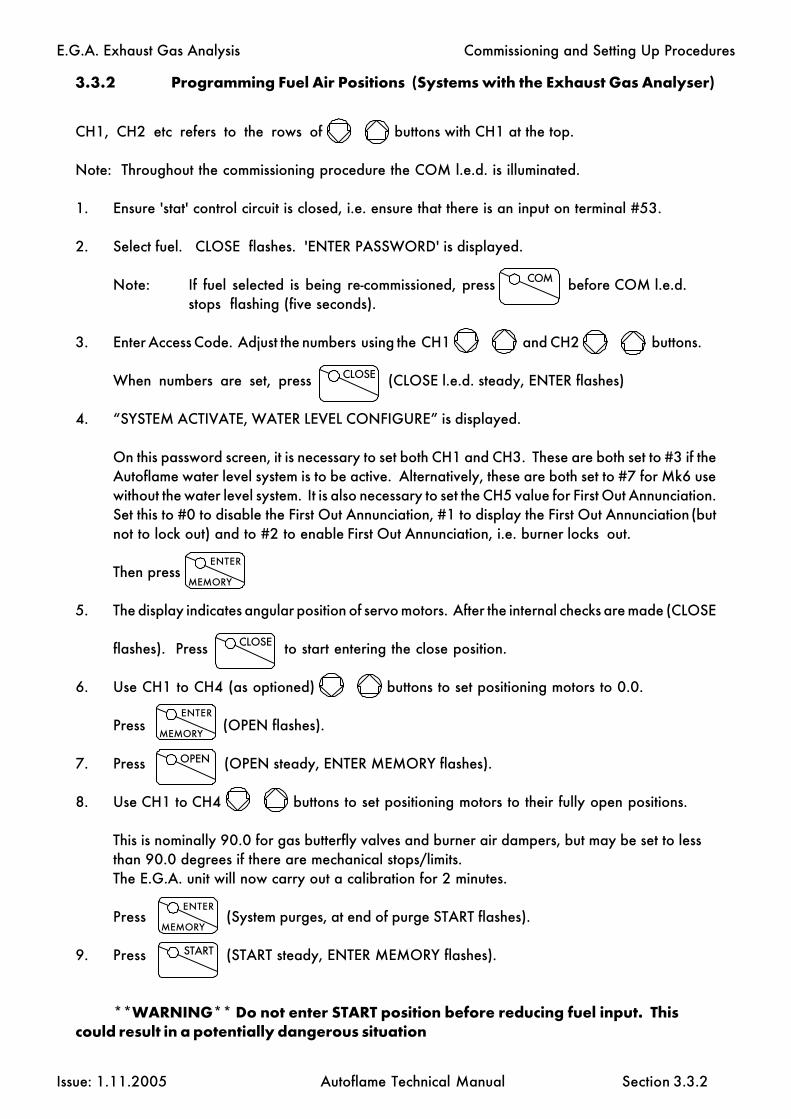
E.G.A. Exhaust Gas Analysis
Issue: 1.11.2005 Autoflame Technical Manual Section
3.3.2 Programming Fuel Air Positions (Systems with the Exhaust Gas Analyser)
CH1, CH2 etc refers to the rows of buttons with CH1 at the top.
Note: Throughout the commissioning procedure the COM l.e.d. is illuminated.
1. Ensure 'stat' control circuit is closed, i.e. ensure that there is an input on terminal #53.
2. Select fuel. CLOSE flashes. 'ENTER PASSWORD' is displayed.
Note: If fuel selected is being re-commissioned, press before COM l.e.d.stops flashing (five seconds).
3. Enter Access Code. Adjust the numbers using the CH1 and CH2 buttons.
When numbers are set, press (CLOSE l.e.d. steady, ENTER flashes)
4. “SYSTEM ACTIVATE, WATER LEVEL CONFIGURE” is displayed.
On this password screen, it is necessary to set both CH1 and CH3. These are both set to #3 if theAutoflame water level system is to be active. Alternatively, these are both set to #7 for Mk6 usewithout the water level system. It is also necessary to set the CH5 value for First Out Annunciation.Set this to #0 to disable the First Out Annunciation, #1 to display the First Out Annunciation (butnot to lock out) and to #2 to enable First Out Annunciation, i.e. burner locks out.
Then press
5. The display indicates angular position of servo motors. After the internal checks are made (CLOSE
flashes). Press to start entering the close position.
6. Use CH1 to CH4 (as optioned) buttons to set positioning motors to 0.0.
Press (OPEN flashes).
7. Press (OPEN steady, ENTER MEMORY flashes).
8. Use CH1 to CH4 buttons to set positioning motors to their fully open positions.
This is nominally 90.0 for gas butterfly valves and burner air dampers, but may be set to lessthan 90.0 degrees if there are mechanical stops/limits.The E.G.A. unit will now carry out a calibration for 2 minutes.
Press (System purges, at end of purge START flashes).
9. Press (START steady, ENTER MEMORY flashes).
**WARNING** Do not enter START position before reducing fuel input. Thiscould result in a potentially dangerous situation
3.3.2
Commissioning and Setting Up Procedures
COM
CLOSE
ENTER
MEMORY
CLOSE
ENTER
MEMORY
OPEN
ENTER
MEMORY
START

E.G.A. Exhaust Gas Analysis
Issue: 1.11.2005 Autoflame Technical Manual Section
10. Use CH1 to CH6 to set positioning motors to positions where ignition cantake place.
11. P r e s s (Burner ignites, HIGH flashes).
12. P r e s s (HIGH steady, EGA flashes).
13. Use CH1 and CH6 to set maximum firing input (it is not possible to exceed the OPEN
position values). Always increase the air first followed by the fuel angular positions.
14. P r e s s (HIGH steady, EGA steady, ENTER flashes) to view the online combustion
readings. If the readings are satisfactory go to step #16, otherwise go to step #15.
15. P r e s s (HIGH steady, EGA flashes).
Make adjustments to fuel and/or air valve positions. Go to step #14.
16. P r e s s (Combination of MM, EGA and RUN flashes).
The system will now carry out 'Auto Commission' routines. No operator intervention will bepermitted during this time. This takes approximately two minutes. While the autocommission istaking place the EGA. and MM. l.e.d.s flash initially (fuel rich autocommission), then RUN andMM flash (air rich autocommission). When finished INTER flashes or INTER and START flash.
Note: Only INTER flashes if the number of INTER positions entered so far is less than or equalto three, thereafter INTER and START flash.
17. P r e s s o r (INTER or START steady, EGA flashes).
18. Use CH1 to CH6 to reduce the Fuel and Air positions. Always reduce the fuel first
followed by the air angular position.
19. P r e s s (START or INTER steady, EGA steady, ENTER flashes).
Observe combustion readings and wait for these values to stabilise. If readings aresatisfactory go to step #22, other wise go to step #20.
20. P r e s s (START or INTER steady, MM steady, EGA flashes).
21. Use CH1 to CH6 to adjust valve settings. Go to step #19.
22. P r e s s (Combination of MM, EGA and RUN flashes).
The system will now carry out 'Auto Commission' routines. No operator intervention will bepermitted during this time. This takes approximately two minutes. While the autocommission istaking place the EGA. and MM. l.e.d.s flash initially (fuel rich autocommission), then RUN andMM flash (air rich autocommission). When finished INTER flashes or INTER and START flash.(If START position has just been entered then RUN flashes).
3.3.2.1
Commissioning and Setting Up Procedures
ENTER
MEMORY
HIGH
E.G.A
1212
M.M.
1212
ENTER
MEMORY
INTER START
E.G.A
123123123
M.M.
123123123
ENTER
MEMORY

E.G.A. Exhaust Gas Analysis
Issue: 1.11.2005 Autoflame Technical Manual Section
If the position just entered was the START position, go to step #24, otherwise go to step #23.
23. Press o r (START or INTER steady, MM steady, EGA flashes).
Go to step #18.
24. P r e s s to set system into normal modulating mode.
25. If an EGA error occurs in commissioning mode, it cannot be reset using the "press close/openbutton". If the fault in the EGA can be cleared the error will reset automatically.
3.3.2.2
Commissioning and Setting Up Procedures
INTER START
RUN

E.G.A. Exhaust Gas Analysis
Issue: 1.11.2005 Autoflame Technical Manual Section
3.3.3 E.G.A. combustion trim operation
With the E.G.A. trim facility it is possible to expand the M.M. so it will measure and display O2 , CO,CO2 and exhaust gas temperature, together with boiler temperature or pressure. At the same time thesoftware within the M.M. unit will inflict minute corrections to the channel 2 air damper positions orthe channel 5 variable speed drive. Channel 2 would normally be controlling the air damper. Theseminute changes ensure that the originally entered commissioning data is adhered to, irrespective ofvariations in stack pressure or barometric conditions.
The system trim function is achieved by every paired value for air and fuel having stored values forO2 , CO2 and CO at the commissioned value. Deviations from these ideal values are held and acces-sible via the "COM" button on the MM facia when in E.G.A mode. This data is integrated and ex-pressed as a degree angular value; this ensures the exact amount of channel 2 or channel 5 trim maybe inflicted at any time to return the system to it’s commissioned value at any load condition.
The E.G.A. control strategy operates error checking self diagnostic software for self identification of systemcomponent or data handling failure.
3.3.3
Commissioning and Setting Up Procedures

E.G.A. Exhaust Gas Analysis
Issue: 1.11.2005 Autoflame Technical Manual Section
3.3.4 Trim Timing Operation
3.3.4
Commissioning and Setting Up Procedures

E.G.A. Exhaust Gas Analysis
Issue: 1.11.2005 Autoflame Technical Manual Section 3.3.5
3.3.5 Graphical Trim Operation
Commissioning and Setting Up Procedures
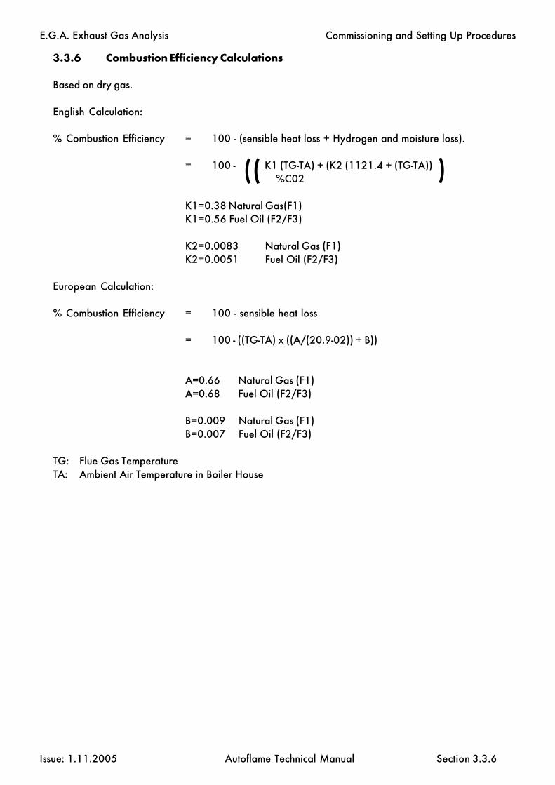
E.G.A. Exhaust Gas Analysis
Issue: 1.11.2005 Autoflame Technical Manual Section 3.3.6
3.3.6 Combustion Efficiency Calculations
Based on dry gas.
English Calculation:
% Combustion Efficiency = 100 - (sensible heat loss + Hydrogen and moisture loss).
= 100 - K1 (TG-TA) + (K2 (1121.4 + (TG-TA)) %C02
K1=0.38 Natural Gas(F1)K1=0.56 Fuel Oil (F2/F3)
K2=0.0083 Natural Gas (F1)K2=0.0051 Fuel Oil (F2/F3)
European Calculation:
% Combustion Efficiency = 100 - sensible heat loss
= 100 - ((TG-TA) x ((A/(20.9-02)) + B))
A=0.66 Natural Gas (F1)A=0.68 Fuel Oil (F2/F3)
B=0.009 Natural Gas (F1)B=0.007 Fuel Oil (F2/F3)
TG: Flue Gas TemperatureTA: Ambient Air Temperature in Boiler House
Commissioning and Setting Up Procedures
(( )

E.G.A. Exhaust Gas Analysis
Issue: 1.11.2005 Autoflame Technical Manual Section
3.4 Error Checking, Self Diagnostics
3.4.1 Key To Errors Detected
Errors detected in the EGA part of the system are indicated when COM or EGA display modes areselected. CH1 --- ERR
CH2 --- EGACH3 --- Error number
Error Number Fault Description
01 No communications to EGA08 O2 Upper limit exceeded09 CO2 Upper limit exceeded10 CO Upper limit exceeded11 O2 Lower limit exceeded12 CO2 Lower limit exceeded14 O2 Absolute limit exceeded (O2 less than specified value)15 CO2 Absolute limit exceeded (CO2 greater than specified value)16 CO Absolute limit exceeded (CO greater than specified value)20 Pump fault --- pump failed/sample system blocked21 O2 Cell failure22 CO2 Cell failure23 CO Cell failure24 Flow pressure switch failure25 Trim threshold exceeded30 NO Upper limit exceeded33 Exhaust temperature upper limit exceeded35 Exhaust temperature absolute limit exceeded (exhaust temperature greater
than specified value)
If any of the above EGA errors occur the action taken will depend on the EGA option selected:(see option #12).
In the event of a fault being detected by the internal fault diagnostic system, contact Autoflame for advice.
Sampling system should be carefully packed in the carton in which was supplied or similar and marked "Fragile- Scientific Instruments" and "Do Not Drop".
When plugs are removed to disconnect the sampling system, the M.M./E.G.A. control module will recognisethat the sampling system has been removed and will run on M.M. values only. The fault Error Code, displayedon the M.M./E.G.A. module will remain displayed but only when the control unit is in the E.G.A. orcommissioning display modes. When it is in the M.M. mode, all normal values and functions would bedisplayed. When the fault has been rectified on the sampling system and it is returned from your dealer, theE.G.A. sampling system can be plugged in and the M.M./E.G.A control module can be put into E.G.A. mode.
The Error Code that is displayed can be cleared by pressing " OPEN" and "CLOSE" simultaneously. Thesystem will now operate normally in the E.G.A. mode and the displays will return to their normal function.
When first going into commissioning mode, the MM invokes an EGA calibration. If an error occurs at this stageit will be necessery to fix the EGA and set commissioning mode again (reselect fuel).
3.4.1
Error Checking, Self Diagnostics

E.G.A. Exhaust Gas Analysis
Issue: 1.11.2005 Autoflame Technical Manual Section
3.4.2 L.E.D. Status Indication
To assist the end user to determine the basic status and fault diagnosis, the P.C.B. is fitted with statusindication in the form of L.E.D.s. The following indications are available:
Green = O.K. System operates correctly.Red = Fault.Yellow = 6 L.E.D.’s each L.E.D. indicates a 2 month operation period.
(1 L.E.D. is extinguished every 2 months- this time is also active during storage).Red = Pressure switch fail (located: right of drain solenoid).Green = Pressure switch proved (located: right of drain solenoid).Red = Vacuum switch fail (located: left of drain solenoid).Green = Vacuum switch proved (located: left of drain solenoid).
see L.E.D. positions.
Once all the yellow L.E.D.s have been extinguished the red L.E.D. will be illuminated, this is an indicationthat the analyser now requires servicing. The service must be carried out by an Autoflame certifiedtechnician or alternatively returned to our factory.
When both the Green & Red LED's are illuminated, this indicates that a service is required, the unit willcontinue to operate in this condition.
* important: when shipping the E.G.A. unit back to our factory, the unit must be returned in the originalpackaging, therefore avoiding additional charges due to transit damage.
3.4.2
Error Checking, Self Diagnostics

E.G.A. Exhaust Gas Analysis
Issue: 1.11.2005 Autoflame Technical Manual Section 3.5.1
3.5 End User Day to Day Operation
3.5.1 Normal Run Operation
Upon initial selection of a commissioned fuel, the display shows F1, F2 or F3 depending on which fuelis selected. The COM l.e.d. flashes for five seconds. During this time a number is displayed in the actualwindow. This number indicates the number of times this fuel has been commissioned. After these 5seconds the M.M. positioning motor values are displayed.
To adjust the required value press and use the required accordingly.
The range of the required value is limited according to the type of sensor being used (see option section).
If the burner control circuit is closed the burner system will sequence through the burner start upprocedure. The system purges and ignites, and twenty seconds (nominal) after ignition the systemmodulates. The four display windows will display values according to the selected display mode.There are four possible display modes: E.G.A. Commission values, E.G.A. Actual values, M.M.Positioning motor values and Status. To select one of the display modes just press:
COM E.G.A. M.M. or respectively.
The respective LED will remain illuminated to indicate which mode is selected. The COM and E.G.A.modes are only selectable if an E.G.A. exists on the system. In the COM and E.G.A. modes thereis a further choice of either Exhaust temperature /Efficiency/CO/NO/SO2. Select these by
pressing accordingly.
In the event of the system being powered down, these selections will be memorised as is all commissiondata, Options and required value. During normal run operation the RUN led is on all the time. Whenno fuels are selected only the RUN LED remains illuminated.
If an E.G.A. is operative on the system it will calibrate every time the burner starts and stops. WhenCOM or EGA display modes are selected 'CAL' is displayed in the Temp/Eff. window when the EGAis calibrating. If the E.G.A. is cooling, 'COOL' is displayed. If the burner is not firing, EGA is displayedin the top window. When the burner is firing and both the COM and E.G.A. modes show 'E.G.A.'in the top window, this indicates that the Actual value has not reached the value at which trimming ispermitted. (See Option 28.) If an E.G.A. error has occurred, the error code number is displayedif either of EGA or COM modes are selected.
The software version number and issue can be displayed on the M.M. by pressing the Channel 1 simultaneously.
Exhaust Temp
Eff %
STATUS
CO NO
INTER
SO2
End User Day to Day Operation
STATUS

E.G.A. Exhaust Gas Analysis
Issue: 1.11.2005 Autoflame Technical Manual Section
3.6 Electrical Schematics
3.6.1 Interconnection between Mk6 EGA and Mk6 MM Module
3.6.1
EGA Unit
Mk6 MM UnitDATA CABLE
NEUTRAL EARTH
LIVE
CONTROL FUSE
to DTICH. 6 I +
CH. 5 I +
CH. 4 I +
CH. 3 I +
CH. 2 I +
CH. 1 I +
4-20mA
Common Analogue Output I -
Fuse Holder
Electrical Schematics

E.G.A. Exhaust Gas Analysis
Issue: 1.11.2005 Autoflame Technical Manual Section
AUTOFLAME
EGA Mk6EGA Mk6
EGA Mk6
3.6.2 Interconnection between Mk6 EGA modules and DTI unit
The control phases to each EGA module & DTI unit must be the same.
The ID must be set for all EGAs connected directly to the DTI.
3.6.2
Electrical Schematics

E.G.A. Exhaust Gas Analysis
Issue: 1.11.2005 Autoflame Technical Manual Section
!!! WARNING !!!
As always observe health and safety procedures. An operator working on the EGA must be of profi-cient technical standard. Take care when removing the front cover of the analyser. If the Analyser ispowered, the cooling fan will be in operation.
3.7.1 Approach to Testing & Calibrating an E.G.A. Mk.6
The information contained in this manual provides a comprehensive understanding and operation ofthe Mk.6 Exhaust Gas Analyser (E.G.A.) units. If using this manual for the first time please read all ofit thoroughly before working on an E.G.A. unit.
The method test and calibration is based on the E.G.A. being connected to PC running the ‘EGA PCCalibration Software’. (This is a standard product available from Autoflame pt No. DTI20018, com-prising software supplied on a diskette and a lead that connects from a PC serial port to the EGA setupport. The lead is identified by red shrouds at each end).
For brevity, the various screens, information and actions that may be carried out on the PC are notcovered in detail in this manual, only a brief overview is given. Operators can quickly familiarisethemselves by working hands on through the various menus on a real system. Throughout the manualany examples of text that are displayed on the PC screen are shown in bold.
To install the software on the PC make a subdirectory on the hard drive, using the DOS copy com-mand, simply copy all files from the diskette to the PC hard drive. To start the program type EGATOPC<return>. (The program runs in DOS only. A mouse is NOT supported). The first time the software isrun select SYSTEM from the main menu. This is the setup of the PC configuration to work as mono-chrome/colour screen, printer port.... can be set. Once all items have been worked through thesettings are stored immediately. The next time the program is run these settings will be restoredautomatically. If the system settings need modifying subsequently then select the SYSTEM menu andchange the settings as desired.
At all times when the EGA is sampling, during day to day operation or testing, it must be kept uprightotherwise condensate may find its way out of the chiller block, into the filter and beyond.
3.7 Testing & Calibration
3.7.1
Test and Calibration

E.G.A. Exhaust Gas Analysis
Issue: 1.11.2005 Autoflame Technical Manual Section
3.8 EGA local display features and capabilities
The following information is provided in order to enable the Autoflame E.G.A. system to be set-up,calibrated and serviced by the end-user. With the local display it is possible to perform all theoperations previously accessed through the EGA to PC software.
To ensure that the combustion readings are correct, it is recommended that the E.G.A. should beeither checked or calibrated once a year. Error codes and fault history displayed on the E.G.A.screen or through the Micro Modulation unit must be observed. The E.G.A. will log up to 10 faults,with the oldest being discarded after 10 faults, and will record the error type and date and timewhen the error occurred.
At any point during the E.G.A. set-up procedure, press to revert back to the online
combustion values. If using an SO2 or NO2 sensor it is necessary to press again to view
these online values.
The online display shows:O2- %CO2- %CO- ppmNO- ppm (if optioned)Ambient temperature- 0C or 0FExhaust gas temperature- 0C or 0FDelta temperature- 0C or 0FCombustion efficiency- %SO2- ppm (if optioned) OR NO2- ppm (if optioned)
3.8
E.G.A. display features
RUN
RUN

E.G.A. Exhaust Gas Analysis
Issue: 1.11.2005 Autoflame Technical Manual Section
3.8.2 E.G.A. Status
Press to view the various E.G.A. status screens.
The first status screen shows:E.G.A. operating mode- with MM or stand aloneSoftware versionFuel selectedDate, month, year and time
Press the button to move to the next status screen. This shows the number of hours run
in each fuel.
Press the button to move to the last of the status screens. This shows when the E.G.A. is
next due for a service. This date will be exactly one year since the unit was sent out, andcorresponds to the 6 amber L.E.D's on the E.G.A. These lights can only be seen when the door isopen (in the bottom left hand corner). One light is extinguished every 2 months, and once thesehave all gone out then the E.G.A. is due a service. It is recommended that each E.G.A. is sent backfor an annual service.
STATUS
1212
STATUS
123123123
STATUS
123123
3.8.1 Fault history
Press to view the fault history log. Up to 10 errors are logged in the E.G.A. and each
error is displayed with the date and time when it occurred. To view the previous 10 errors in time
sequential order press to move through each one.
FAULTHISTORY
123123123
FAULTHISTORY
1212
3.8.1
E.G.A. display features

E.G.A. Exhaust Gas Analysis
Issue: 1.11.2005 Autoflame Technical Manual Section
3.8.2 E.G.A. local display set-up guide and calibration options
3.8.2.1 E.G.A. set-up guide
To enter the set-up mode, firstly press the button to display the online combustion values.
Press to enter the set-up mode. Once this button is pressed the password screen will
activate. Enter the password using the CH1 and CH2 buttons. The CH1
buttons change the units and the CH2 buttons change the tens value.
Once the correct password has been entered, press to enter the "SELECT FUNCTION"mode.
3.8.2.1 Select Function
The "SELECT FUNCTION" screen is displayed.
Use the CH1 buttons to select the function to be changed. Once the desired function is
selected, press to change the settings for that function.
The various settings you can change include:Setting the date and timeConfiguration of the E.G.A.Configuration of the six 4-20mA outputs
3.8.2.2 Setting the date/time
Once "SET DATE/TIME" is displayed press
The CH1 buttons scroll through the various options to change,
i.e. date, month, year, hour and minute.
The CH2 buttons change the actual value for each option.
Once the date/time has been set, press to return to the "SELECT FUNCTION" menu.
COM
COM
ENTER
MEMORY
ENTER
MEMORY
ENTER
MEMORY
RUN
3.8.2
E.G.A. display set-up guide

E.G.A. Exhaust Gas Analysis
Issue: 1.11.2005 Autoflame Technical Manual Section
3.8.2.3 Configuration of the E.G.A.
Once "E.G.A. CONFIGURE" is displayed press
The CH1 buttons scroll through the various settings that can be changed. When the
desired setting is displayed, press to start making any changes.
The settings that are adjustable through the "E.G.A. CONFIGURE" menu include:
(For each setting the function of CH1 and CH2 buttons are shown)
CH1 CH2
Operating mode with MM or stand alone no function
Temperature unts imperial or metric no function
Efficiency calculation english or european no function
ID number 1-10 no function
NO sensor fitted or not fitted no function
SO2 sensor fitted or not fitted no function
CO/NO pinch valve selects fuel selects open or close
Change the password units tens
Once the required changes are made for a particular selection, press to move to the next
selection, i.e. after changing the ID number press to move to the NO sensor selection.
Once all required changes have been made, use the CH1 buttons to scroll to the
"RETURN TO SELECT FUNCTION" screen and press
ENTER
MEMORY
ENTER
MEMORY
ENTER
MEMORY
ENTER
MEMORY
ENTER
MEMORY
3.8.2.3
E.G.A. display set-up guide

E.G.A. Exhaust Gas Analysis
Issue: 1.11.2005 Autoflame Technical Manual Section
3.8.2.4 Configuration of the six 4-20mA outputs
Once the "4-20mA OUTPUTS" screen is displayed, press to set the correct outputs andsignal range.
The CH1 selects which output (1-6) is to be changed. When the correct ouput is
displayed press to make the changes.
Use the CH1 to select which output signal is required.
The possible output signals are listed below:O2- %CO2- %CO- ppmNO- ppmExhaust temperature- 0C or 0FEfficiency- %SO2- ppmSmoke densityAir temperature- 0C or 0FAmbient temperature- 0C or 0FReady Status
Once the desired output signal is selected press . For each output (1-6) and chosen
output signal it is necessary to set a range (4-20mA).
Firslty the lower range is set (4mA). The CH1 changes the units (i.e. 0.1%, 1ppm,e.t.c)
and the CH2 changes the tens (i.e. 1.0%, 10ppm, e.t.c). When the correct lower range
is set press .
Next the upper range is set (20mA). The CH1 changes the units (i.e. 0.1%, 1ppm,e.t.c)
and the CH2 changes the tens (i.e. 1.0%, 10ppm, e.t.c). When the correct upper range
is set press .
The next 4-20mA signal will now need to be set. Once these are all set (or the desired ouputs are
set), use the CH1 buttons to scroll to the "RETURN TO SELECT FUNCTION" screen and
press , or press to return to the online cambustion values.
ENTER
MEMORY
ENTER
MEMORY
ENTER
MEMORY
ENTER
MEMORY
ENTER
MEMORY
ENTER
MEMORY
RUN
3.8.2.4
E.G.A. display set-up guide

E.G.A. Exhaust Gas Analysis
Issue: 1.11.2005 Autoflame Technical Manual Section
3.8.3 Changing the cells and test gas calibration
This section describes the procedure for changing out the cells of the E.G.A. in the field and alsoapplying a test gas to calibrate the cells.
When in the normal operating mode, i.e. the button is illuminated. Hold down the
button for 2 seconds in order to enter the calibration menu. Once this is done the
"CALIBRATION METHOD" menu will appear.
Use the CH1 buttons to select which calibration method is to be used. The 2 choices are
"CALIBRATION CODE" and "GAS CALIBRATION". Once the correct screen is displayed press
to proceed.
3.8.3.1 Calibration code
Once has been pressed "SELECT CELL TYPE" will appear. Use the CH1 to
select the cell that is to be replaced and then press
It is now necessary to enter the 15 digit code. This code contains information regarding themanufacture date and range it was set for.
To do this use the CH1 buttons to move left and right to select the digit to change. Then
use the CH2 buttons to change the value for each digit.
Once the correct code has been entered press
If the wrong code has been inputted, then "INCORRECT CODE" is displayed. Press to
return to the "SELECT CELL TYPE" screen and start again.
Press when finished to go back to the online combustion values.
RUN
CAL
123123
ENTER
MEMORY
ENTER
MEMORY
ENTER
MEMORY
ENTER
MEMORYENTER
MEMORY
RUN
3.8.3
E.G.A. display calibration method

E.G.A. Exhaust Gas Analysis
Issue: 1.11.2005 Autoflame Technical Manual Section
3.8.3.2 Gas calibration
Once has been pressed "SELECT CAL GASES" is displayed. Use the CH1 to
select the gas and use CH2 to select "YES/NO" for each gas.
Once the correct test gas constituents are selected press to continue.
"SET GAS SPANS" will be displayed. Now it is necessary to set the percentage of each gas is thetest gas.
Use CH1 buttons to select the gas and the CH2 buttons to select the
percentage for each gas.
Once this is set press to continue. The E.G.A. will perfrom a zero calibration and then the
"CONNECT CAL GAS" screen will be displayed. Once the test gas is connected, and the flow is set
with the flow gauge (550-600cc), press to perfom the test gas calibration.
Press once this is finished to return to the online combustion values.
ENTER
MEMORY
ENTER
MEMORY
ENTER
MEMORY
RUN
ENTER
MEMORY
3.8.3.2
E.G.A. display calibration method

E.G.A. Exhaust Gas Analysis
Issue: 1.11.2005 Autoflame Technical Manual Section
3.9 EGA Set-up Software Introduction
The following information is provided to enable the Autoflame E.G.A. System to be calibrated andserviced by the user.
The software is operating a context sensitive help system. This means that by pressing the F1 func-tion key you will get a help message specific to the function selected in the program. If you areunable to find the HELP you require in the software notes go to the desired function in the programand press F1.
The E.G.A. calibration software is accessed using an IBM PC or compatible, running MSDos to-gether with the software and data cable provided. The PC operates via the RS 232 serial port, eitherCOM1 or COM2 and the corresponding serial port in the E.G.A. (see diagram 3.1.3) The serialport in the E.G.A. is a 9 pin ‘D’ type connector on the cell board. The dust cover on the Dconnector must be replaced after use.
To ensure the combustion readings are correct the E.G.A. should be either checked or calibratedonce a year. Error codes and information displayed on the remote display Pod (used for StandAlone Analyser) or the Micro Modulation unit (used for combustion trim) must be observed.
The E.G.A. will log faults and retain the types of fault stating the date the fault occurred. Up to 10values will be logged with the oldest fault being discarded. The logged values may be displayed onthe PC.
Once connected it is important to establish communication is correct. This is displayed on the PCscreen, top left, with the message “EGA Communicating OK”.
Should there be a communications problem please check the following points:
1) The data cable that is being used is the correct type as supplied with the software.2) All interconnections are correct and secure.3) The E.G.A. is powered and operational.4) The correct serial port is selected from the software, (COM1 or COM2)
3.9
2 Metres
Cable & Disk Part No. DTI20018
Serial Connectionto Computer (red)
Connection to E.G.A.Serial Port (red)
3.5" Floppy Disk (EGADISK)
EGA Set-up Software Introduction

E.G.A. Exhaust Gas Analysis
Issue: 1.11.2005 Autoflame Technical Manual Section
3.9.0.1 Software Possiblities
The E.G.A. 6 channel output facility is PC configurable to enable the user to set the range and items ofdata required and also user selectable. Via the same software and connection lead (part no. DTI 20018)the E.G.A. can be configured and operated as required, this can also be used to service, fault find andcalibrate the unit in two ways:-
Replacement sensors are supplied pre-coded which is entered into the EPROM of the unit tocalibrate the cell.
Selecting the output signals of the 4-20mAThere are eleven possibilities:-
1. O2 range adjustable
2. CO2 range adjustable3. CO range adjustable4. NO range adjustable5. SO2 range adjustable.6. Exhaust gas temperature7. Efficiency/nett/gross8. Input for ambient air temperature i.e. combustion air inlet on burner9. Air temperature input 4-20mA10. E.G.A. unit air temperature ambient11. Smoke density auxiliary input/output 0-10v from smoke obscuration 4 to 20 mA output.
3.9.0.1
EGA Set-up Software Introduction
E.G.A. Exhaust Gas Analysis
Issue: 1.11.2005 Autoflame Technical Manual Section 3.9.1
3.9.1 Using The Software
Calibrate Sensor (Replacing a Sensor)
The use of this facility will enable the user to calibrate the sensors within the E.G.A.. Each sensor issupplied by Autoflame complete with it’s own unique calibration code number.
step 1. Removing the sensor to be replaced,
a) For O2 and CO2 sensors disconnect the corresponding plug associated with the sensor and thetwo plastic tubes, now remove the sensor retaining strap and install the new sensor following the stepsin reverse order.
b) For CO, SO2 and NO sensors, disconnect the corresponding plug associated with the sensor, nowremove the three screws located on the top of the sensor, only replace the sensor head. Do not removethe plastic tubing from the sensor housing.
step 2. Select Calibrate Sensor from the tool bar displayed at the bottom of the screen page. Thiscommand will allow you to change a sensor without the need for test calibration gas.
step 3. After selection of the desired type of sensor from the menu listing, press the Enter key.
step 4. Type in the calibration code at the prompt and type Enter.
step 5. The E.G.A. communications will update the P.C. with information regarding the types ofsensor fitted, i.e. CO, NO, SO2 , CO2 and O2 .
step 6. Changing of the Sensor is now complete, remove serial connection and replace coveron the E.G.A. unit. If the cover is left off the E.G.A. the internal components may over heat due to lackof cooling air from the fan located on the base of the unit. If the internal temperature is above +40 degC or below +5 deg C the Pod or M.M. unit will display “EGA HI” or “COOL” respectively.
NOTE* Only sensors purchased as spares have a code number issued.
EGATOPC Software

E.G.A. Exhaust Gas Analysis
Issue: 1.11.2005 Autoflame Technical Manual Section
3.9.2 Status
When the status toolbar option is selected the P.C. will display all the information from the E.G.A. unit.The information will only be received provided the E.G.A. is communicating with the P.C. Ensure theE.G.A. is powered.
The Status screen will display the following information typically:
EGA Identification Number: 1Operating Mode: EGA with MMOperating Status: Ready for operationMonitoring: Oxygen O2
Carbon Dioxide CO2
Carbon Monoxide 1 CONitrous Oxide NOSulphur Dioxide SO2
Run Time (Fuel 1) 433 HoursRun Time (Fuel 2) 120 HoursRun Time (Fuel 3) 10 Hours
Note: The above information is an example of Status information available
3.9.3 Faults
The Faults screen page shows the listing of all fault conditions that have occurred on either the M.M.unit or the Stand alone display Pod. Up to 10 faults can be stored and displayed after this, subsequentfaults will erase the oldest fault listed. The date the error was detected and the Error number will alsobe listed.
Example:
1 : 12/09/96 O2 cell failed (21) Error number2 : 04/10/96 Pump failed (20) Error number
3.9.2
EGATOPC Software

E.G.A. Exhaust Gas Analysis
Issue: 1.11.2005 Autoflame Technical Manual Section
3.9.3 Options
This facility allows the user to select those options for the desired operation of the software. The usercan configure the various options by pressing the Enter key when set to the required menu. OnceOptions has been selected the Configuration Menu will be displayed, showing the following menuoptions.
3.9.3.1 4 - 20mA Outputs
As standard the Mk.6 E.G.A. unit is supplied with 6 channels of 4 - 20mA. The user can programme therequired output from the function menu and configuring to the desired range. The minimum output is4mA the maximum output is 20mA, each can be set to the range required.
An external PSU is not required for the analogue outputs. The maximum permissable load on eachanalogue output is 250Ω. All the negative terminals are common to each other. The analogue outputsas a whole are isolated.
3.9.3.2 EGA Operating Mode
The EGA Mode Setup allows the user to select the type of sensors and the desired operation on theanalyser. The menus for each option show the selection available at each point. Use the Enter key tomove to the next value, use ‘Y’ to denote selection of the NO and SO2 sensors, or ‘N’ if not in use.When selections are complete press Enter.If you select this option but decide not to change any values press the Escape key.
Setup configurations available:
Identification NumberCO Sensor typeStand Alone or MM operationEfficiency CalculationNO2 Sensor fittedSO Sensor fitted
Standard Factory Setup
CH No. Selection Min Max
CH1 O 0 20.9
CH2 CO 0 15
CH3 CO 0 999
CH4 NO 0 999
CH5 Deg C 0 400
CH6 Eff % 0 100
2
2
3.9.3.1
EGATOPC Software

E.G.A. Exhaust Gas Analysis
Issue: 1.11.2005 Autoflame Technical Manual Section
3.9.3.3 Pinch Valve Control
This facility allows the user to measure CO and NO when operating on F2 or F3 fuel programmes. Asstandard, CO and NO will only be measured when operating on fuel programme F1 programmeshould always be used for the operating of gas firing. This facility may be required if gas is operatingon F2 programme or the user would like to measure CO and NO when burning fuel oil.
V1 = Pinch valve No.1 .(Brown) This pinch valve is located at the top of the cell P.C.B. .Second from theleft, with a brown top to the valve.V2 = Pinch valve No.2: SO2 Pinch valve
To check the pinch valves operate correctly:
The Pinch valves are checked in the M.M. Run mode. Select fuel 1 (F1), Press E.G.A. to display theE.G.A. information. Check that pinch valve 1 is open. The black topped pinch valve should close whenan E.G.A. calibration takes place, at this stage the sample line is closed and the drain solenoid isopened. At all other times (i.e. when no calibration is taking place) the black topped valve should beopen.
Select fuel 2. Check pinch valve 1 is closed all the time Fuel 2 is selected. Unless this has beenchanged by the user as described earlier in Pinch Valve Control.
V1 Pinch valve No.1V3 pinch valve. V2 Pinch valve No 2.
3.9.3.3
EGATOPC Software
E.G.A. Exhaust Gas Analysis
Issue: 1.11.2005 Autoflame Technical Manual Section
3.9.3.4 System Configuration.
This function allows the user to select the following:Language: English, German or French.Serial Port: 1 or 2Monitor: Colour: Yes or NoPrinter Port: PRN as standardBaud Rate: 9600 as standard
3.9.3.5 Test and Calibration Menu.
Options available:a. Enter report detailsb. Set time and datec. Clear fault recordsd. Print reporte. Modify Distributor detailsf. Load fault record to diskg. Sensor calibration datesh. Return to main menu
3.9.3.6 Return to Main Menu (press ESC key)
3.9.3.7 Quit.
This will return the user to the DOS prompt.
3.9.3.4
EGATOPC Software

E.G.A. Exhaust Gas Analysis
Issue: 1.11.2005 Autoflame Technical Manual Section
3.10 Limits on Three Measured Combustion Parameters O2 ,CO, CO2
3.10.1 Overview of System Operation: Features and Benefits.
The limits control software, which is included in every M.M. E.G.A. module, further extends theapplication and control possibilities of the system when the E.G.A. sampling system is fitted. The functionof the Limits control software enables the end user or commissioning engineer to insert upper and lowerlimits on either or all of the three combustion parameters that the E.G.A. system measures; O2, CO2, CO.To invoke this additional control facility, follow the commissioning data and technical information sheetwithin this section.
The Limits control software is configured in two distinct forms: “Standard” Limits or “Absolute” Limits.Either configuration is a user variable selection via the Options listing detailed and listed elsewhere inthis publication.
“Standard” Limits:
“Standard” Limits are a set percentage volume above or below the commissioned value for O2 and CO2.In the case of CO, it is a specific amount of p.p.m. (parts per million) above the commissioned value.These values are entered when commissioning of the E.G.A. system has been completed throughout theload index of the burner.
“Absolute” Limits:
“Absolute” Limits are a specific percentage volume (numerical value). In this form only an ultimate lowvalue may be put on O2 in percentage volume and an ultimate high value for CO2 in percentage volume:In the case of CO, an ultimate high value in p.p.m. may be entered. These values are entered whencommissioning of the E.G.A. system has been completed throughout the load index of the burner.
The values for either “Absolute” or “Standard” Limits are implemented via the Micro ModulationController options. When an entered Limit is exceeded, either in “Absolute” or “Standard” configura-tion, the following alternative control functions are available to the user: (Selected via Options).
Control Function 1.
The Trim function is turned off automatically and the system runs on M.M. fuel and air positions only.Also an Error value is displayed (See ERRor listings). The error value displayed can be cleared and theTrim function reinstated by pressing the “Open” and “Close” buttons on the switch facia simultaneously.
Control Function 2.
The combustion system is shut down (the CR relays are opened). Also an error value is displayed (SeeError listings). The error value displayed can be cleared and the combustion system restarted by pressingthe “Open” and “Close” buttons on the switch facia simultaneously.
(See relevant data sheets and drawings showing the control forms and facilities detailed above).
3.10.1
Limits on Three Measured Combustion Parameters O2 ,CO, CO2

E.G.A. Exhaust Gas Analysis
Issue: 1.11.2005 Autoflame Technical Manual Section
3.10.2
3.10.2
Limits on Three Measured Combustion Parameters O2 ,CO, CO2

E.G.A. Exhaust Gas Analysis
Issue: 1.11.2005 Autoflame Technical Manual Section
3.10.3
3.10.3
Limits on Three Measured Combustion Parameters O2 ,CO, CO2
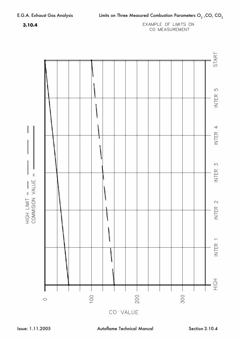
E.G.A. Exhaust Gas Analysis
Issue: 1.11.2005 Autoflame Technical Manual Section
3.10.4
3.10.4
Limits on Three Measured Combustion Parameters O2 ,CO, CO2

E.G.A. Exhaust Gas Analysis
Issue: 1.11.2005 Autoflame Technical Manual Section
3.11 EGA Dimensions
3.11
If EGA is in a hot area, cool air should be directed from a lower level or from outside with a filter.
EGA Dimensions and Fixing Details

E.G.A. Exhaust Gas Analysis
Issue: 1.11.2005 Autoflame Technical Manual Section
3.12.1 Installation and Maintenance
E.G.A. Sampling Probe Installation.
Mount the sampling probe at an angle of approximately 45 degrees.
Install a 1.5" B.S.P. socket on the flue or other point that sampling probe is to be positioned.
Mount the main body of the probe as far in as possible; adjustment is made by loosening thegrub screws in the flats of the 1.5" B.S.P. bush supplied on the probe.
Keep the thermocouple cable and sample tube away from hot surfaces.
NOTE*For correct EGA operation, the probe must be positioned without air leaks as this will give incorrectreadings on all sensors.
E.G.A. Sampling System Unit Installation
Push the sample tube onto the inlet tube. Plug the thermocouple connector into the socket andtighten the screw.
To obtain optimum performance and reliability do not mount the unit in ambient temperaturesabove 45 degrees C. or areas of direct heat radiation. Ensure that the air flow to the intake in thebottom of the E.G.A. unit is not impeded and the air temperature is less than 45 degrees C.
Do not mount the units where excessive vibration occurs (floor standing racks are available fromAutoflame Eng.).
Position the sample tube so that the sample slopes down to the EGA unit at all times.The E.G.A. unit must always be mounted lower than the EGA probe.
Diagram to Show Correct Mounting/Fixing Position.
3.12.1
CorrectFixing.
IncorrectFixing.
Probe
Sample TubeMk.6 E.G.A.
UnitMk.6 E.G.A.
Unit
3.12 Standard EGA Sampling Probe
Standard EGA Sampling Probe
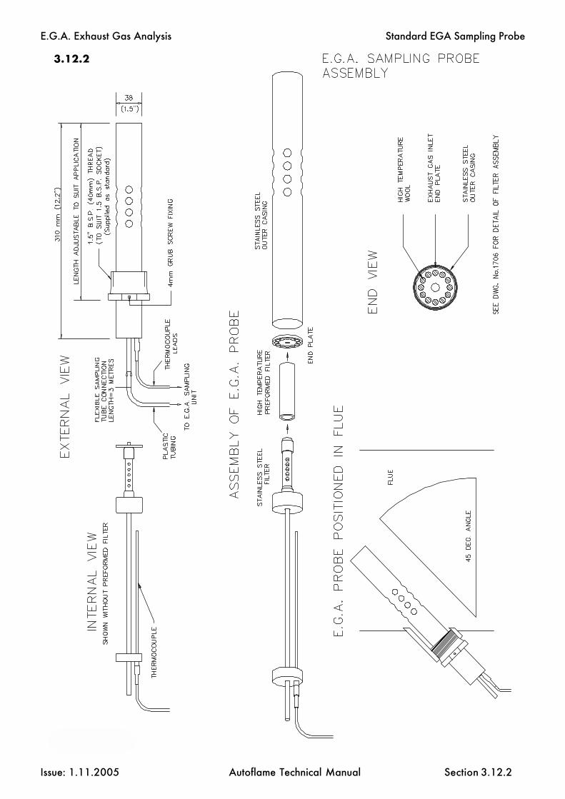
E.G.A. Exhaust Gas Analysis
Issue: 1.11.2005 Autoflame Technical Manual Section
3.12.2
3.12.2
Standard EGA Sampling Probe

E.G.A. Exhaust Gas Analysis
Issue: 1.11.2005 Autoflame Technical Manual Section
3.12.3
3.12.3
Standard EGA Sampling Probe

E.G.A. Exhaust Gas Analysis
Issue: 1.11.2005 Autoflame Technical Manual Section
Outlet Tube
Drill
Mounting Bush
On gas only applications it is unlikely that there should be any maintenance on the stack mountingprobe. On heavy or solid fuel applications, deposits may build up in the outlet part of the tube. Ifthe tube blocks “ERR EGA 20” will be displayed on the M.M. unit (See Section 3.3.1).
The deposits can be cleared by running a long drill (7mm)(.275") up into the outlet tube by hand. Twistand withdraw the drill often so as to pull out the deposits, otherwise the deposits will be pushed furtherinto the probe assembly.
Sectional Diagram to Show Method of Clearing a Blocked Outlet Tube.
3.12.4 Maintainance of Sampling Probe
3.12.4
Standard EGA Sampling Probe

E.G.A. Exhaust Gas Analysis
Issue: 1.11.2005 Autoflame Technical Manual Section
3.12.5 Installation Precautions
The reliability of the equipment may be impaired if used in environments where strong electro magneticfields exist. If for example the equipment is installed in a boiler house at the top of a high rise buildingwhere radio systems exist then additional EMC (Electro Magnetic Compatability) measures may haveto be considered
3.12.5
Standard EGA Sampling Probe

E.G.A. Exhaust Gas Analysis
Issue: 1.11.2005 Autoflame Technical Manual Section
3.12.6 Servicing E.G.A. Sampling Probe.
If the filter assembly in the E.G.A. sampling probe is blocked then it is necessary to disassemble the probeand fit a new pre-formed fine filter and coarse filter material. To check if the E.G.A. probe is blockedconnect it to the E.G.A. If the flow drops by more than 100 cc/min. then the filtering materials must bereplaced.
To disassemble the probe, remove the two cap headed screws visible on the outside of the assembly (oneeach end). The whole of the internal assembly can now be withdrawn from the sample connection end.Remove all traces of the filtering materials from the stainless steel filter. Check that the ways in thestainless steel filter are clear and also the inner sample tube. Very carefully (the pre-formed fine filteris delicate) push the pre-formed filter onto the stainless steel filter.Slide the inner assembly back into the stainless steel outer casing. Pack the void between the fine filterand the outer casing with coarse filtering material as shown on the Filter Assembly Diagram. Use a smallrod to pack the material down a little at a time. Reassemble the Exhaust Gas Inlet End Plate and the twoscrews.
After reassembly connect the probe to the E.G.A. and check that the drop in flow is no more than50 cc/min.
Plug in the thermocouple lead and set the M.M. to read E.G.A. Values in Commissioning Mode. Applyheat to the thermocouple (put a soldering iron through the holes in the outer casing) and check that thethermocouple gives a reading.If there is any doubt to the accuracy of the thermocouple then replacement is advised.
3.12.6
Standard EGA Sampling Probe

E.G.A
. Exhaust Gas A
nalysis
Issue: 1.11.2005A
utoflame Technical M
anualSection
3.13
3.13M
k.6 EG
A Interna
l Tubing
Pipew
ork
SAMPLE IN
SO2 EXHAUST(YELLOW RING)
DOUBLEPINCH VALVE No.1
BACK (N/C)
FRONT (N/0)
CO/NO BYPASS(BLUE RING)
CO CELLEXHAUST
(RED RING)
AT THIS POINTCHECK FLOW OF PUMP
IS 600-650cc/min
VACUUM SWITCH
DRAIN
CO2 CELL O2 CELL
GLASSRESTRICTOR
3mm PVC TUBE
PRESSURE SWITCH
DRAIN SOLENOID
GLASSRESTRICTOR
(BLACK TOPPED PINCH VALVE)SINGLE PINCH VALVE (N/0)
SO2 ATMOSPHERIC AIR INLET(GREEN RING)
FRONT (N/C)
BACK (N/O)
DOUBLEPINCH VALVE
SO2 CELLGLASS
RESTRICTOR
EGA 24V PUMP
CO CELL NO CELL
DRY FILTER
CHILLER BLOCK
EGA 24V PUMP
Internal Tubing

E.G.A. Exhaust Gas Analysis
Issue: 1.11.2005 Autoflame Technical Manual Section
3.14.1 Overview.
3.14.2 Operation.
3.14.3 Maintenance.
3.14.4 Standard Setup.
3.14.5 Fault Finding.
3.14.6 Technical Specifications.
3.14.7 General Assembly of Bubble Filter & EGA Display Pod.
3.14.8 Plan view of Connection (Actual & Schematic)
3.14.9 Enlarged View of Bubble Filter Pot top cap Connections.
3.14.10 Wiring Diagram Display Pod & EGA Sampling Unit.
3.14.11 Mk.6 EGA Internal Layout (Shown without cover)
3.14.12 General Assembly of Dry Filter.
3.14.13 General Assembly & Exploded View of Particulate Filter.
3.14.14 General Assembly of Bubble Pot.
3.14.15 "S" Type High Temperature Thermocouple Assembly.
Section 3.14 E.G.A. with Bubble Filter
3.14 Index

E.G.A. Exhaust Gas Analysis
Issue: 1.11.2005 Autoflame Technical Manual Section
3.14.1 Overview
The Exhaust Gas Analyser in its standard form is a tried tested and approved apparatus for the continu-ous on-line monitoring of exhaust gases on packaged boiler plant.
The versatility of the product enables monitoring of all types of commercially available fuels on bothpackaged light, commercial & industrial process plant.
For Clinical waste incineration there are 3 parameters of importance to the environmental authorities:-O2 , CO, & Exhaust gas temperature.
The use of electro chemical cells enables a cost effective package offering the accuracy required forclinical waste monitoring.
The "Bubble Pot" continuous wash filter ensures all acids & metals are absorbed from the samplebefore entering the EGA unit, preventing a corrosive attack of the system.
Data from the unit is available in two forms:-1. Remote Display Pod2. 6 x 4-20mA outputs for connection to PLC
The unit carries out nightly "Autocal" checks to ensure the cells are operating within specified toler-ances. Any discrepancies are signalled on the display pod facia using the error codes detailed insection 5
A PC software package & lead are available which allow a service technician to carry out simple setup& calibration tasks. Replacement cells are supplied with their own unique calibration no.When a cell is replaced the calibration number is entered via the PC ensuring minimum downtime andcostly on site service charge. (Part No. DTI120018)
3.14.1
EGA with Bubble Filter

E.G.A. Exhaust Gas Analysis
Issue: 1.11.2005 Autoflame Technical Manual Section
3.14.2 Operation
The E.G.A. & filters are designed to operate with the minimum amount of user input.
The unit is supplied prewired & prepiped ensuring simple installation.
Section A1 shows a typical layout for the unit with all connection information detailed separatelyunder their respective figure illustrations.
Day to day Operation.
Once installed all necessary inputs & outputs are automatic.
The unit must always be powered.
A mains 230Vac input on terminal 7 tells the unit when to start sampling. This signal should come fromthe PLC & should be set to give an output when the furnace temperature has reached 1000 deg C.
NB. Experience shows that when the furnace is below 1000 deg C considerable amounts of unburntash/solids are given off which quickly block the sampling system. It is not advisable to control theprocess until the combustion has reached a steady state condition.
Setting up Water Flow.
Water input must be greater than water out through the drain,.The greater the water flow, the more acids are absorbed from the sample.Ideally water "in" should = water "out", however on initial start-up the filter would not be able tofill,therefore the water "in" should be slightly greater than the water "out". If the difference is too greatthe water "in" solenoid will be constantly be turning on & off creating a pulsed sample, a controlregulating valve on the inlet water line will enable optimum setup.
3.14.2
EGA with Bubble Filter

E.G.A. Exhaust Gas Analysis
Issue: 1.11.2005 Autoflame Technical Manual Section
3.14.3 Maintenance
The on/off signal for sampling is controlled by the PLC.
Daily Checks
1. Check the condition of the hot filter on the end of the probe.experience shows that this needs replacing every 2 to 3 days dependingon waste being burnt. (see section A1)
2. Check there is a gentle flow of water from the bottom of the Bubble Filter.
The unit has self diagnostic error checking software & any fault conditions are notified via error codeson the facia. (see fault finding Section 3.14.5)
Monthly Checks
4. Remove EGA lid and visually check the condition of the E.G.A. "Dry" filter, (see section3.14.12) the condition of this filter varies greatly with the type of waste being burnt.All the following conditions necessitate change:-
a) Discoloration of the wool filter.b) Build up of white deposit in the filter.c) Any signs of condensate.
3.14.3
EGA with Bubble Filter

E.G.A. Exhaust Gas Analysis
Issue: 1.11.2005 Autoflame Technical Manual Section
3.14.4 Standard Setup
The EGA is setup to work with a display pod & Bubble Pot. If any item is not connected an errorcondition will be signalled.
4-20mA Output Setup
The above are factory set. These can be changed at time of manufacture or by the user with the aid ofthe EGATOPC software disk & lead.
CHANNEL DESCRIPTION 4mA 20mA
1 O2% 0 16
2 - - -
3 CO ppm 0 200
4Type "K"
Thermocouple500 1600
5Type "S"
Thermocouple 500 1600
6Fault -
-operationalFault Operational
3.14.4
EGA with Bubble Filter
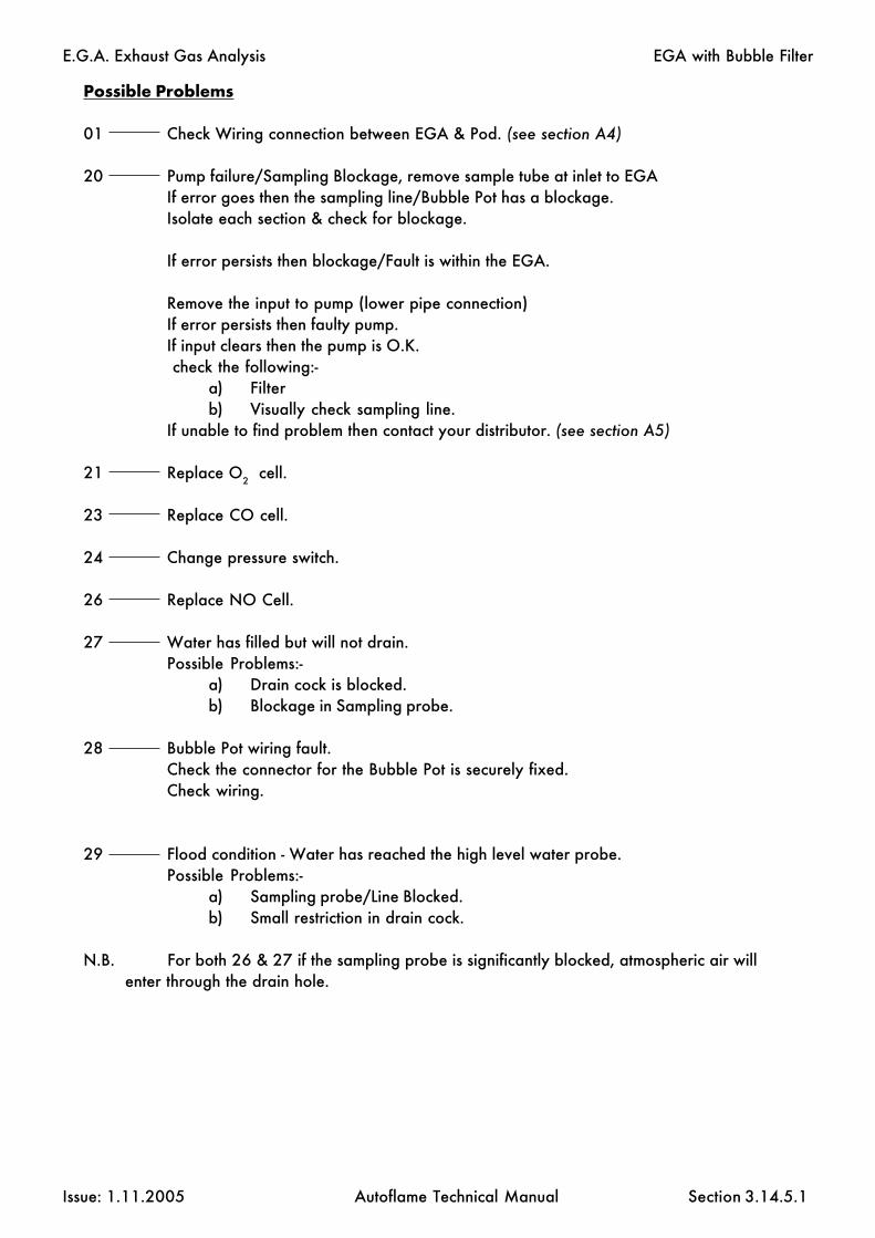
E.G.A. Exhaust Gas Analysis
Issue: 1.11.2005 Autoflame Technical Manual Section
Possible Problems
01 Check Wiring connection between EGA & Pod. (see section A4)
20 Pump failure/Sampling Blockage, remove sample tube at inlet to EGAIf error goes then the sampling line/Bubble Pot has a blockage.Isolate each section & check for blockage.
If error persists then blockage/Fault is within the EGA.
Remove the input to pump (lower pipe connection)If error persists then faulty pump.If input clears then the pump is O.K. check the following:-
a) Filterb) Visually check sampling line.
If unable to find problem then contact your distributor. (see section A5)
21 Replace O2 cell.
23 Replace CO cell.
24 Change pressure switch.
26 Replace NO Cell.
27 Water has filled but will not drain.Possible Problems:-
a) Drain cock is blocked.b) Blockage in Sampling probe.
28 Bubble Pot wiring fault.Check the connector for the Bubble Pot is securely fixed.Check wiring.
29 Flood condition - Water has reached the high level water probe.Possible Problems:-
a) Sampling probe/Line Blocked.b) Small restriction in drain cock.
N.B. For both 26 & 27 if the sampling probe is significantly blocked, atmospheric air willenter through the drain hole.
3.14.5.1
EGA with Bubble Filter

E.G.A. Exhaust Gas Analysis
Issue: 1.11.2005 Autoflame Technical Manual Section
Other Possible Problems
Fuse keeps blowing.
If the EGA is mounted in an excessively dusty environment a build up of particles on the terminals cancause arcing. If the particles are corrosive then any attack to the conformal coating on the printedcircuit boards can cause tracks to arc & component failure. Any sign of this activity & the unit shouldbe returned to the supplier.
Continuous O2 Reading at 20.9%Check all piping is airtightCheck sample tube is not blocked.Check air solenoid is closed.Check air is not being drawn from the Bubble Pot drain.Check Bubble Pot head for cracks.
!!Warning!!The Bubble Pot head is made of a corrosive resistant medical grade plastic, the top is drilled & tappedto accept the small tapered pipe fittings,the Bubble Pot is working at a minimal pressure of 10" WG.Fittings need only be finger tight, overtightening these tapered fittings will build up mechanical stressin the plastic resulting in hairline cracking.
Water level
If the water level continually oscillates no sampling takes place, depending on the type of water beingused, electrolysis can cause a build up of non conducting solids on the water level probes. This issimply cured by cleaning the probes (see Section A5.4 for assembly of Bubble Pot)
High displayed on Pod Facia.
The ambient is in excess of 40 deg C and the chiller cannot cool down.
Low displayed on Pod Facia.
The ambient temp is less than 5 deg C
3.14.5.2
EGA with Bubble Filter

E.G.A. Exhaust Gas Analysis
Issue: 1.11.2005 Autoflame Technical Manual Section 3.14.6
3.14.6 Technical Specifications
Electrical Supply:- 230V/50Hz or 110V/60Hz (Selectable)
Pump Flow:- 0.5L @ 60" W.G.
Water Supply:- This should be a constant head of between 10' & 15' of clean waterfrom the header tank,DO NOT CONNECT DIRECTLY TO THE MAINS SUPPLY
Temperature Range:-
Min. +10 deg CMax. +40 deg C
Ceramic sampling Probe 0 - 1600 deg C
Type "S" Thermocouple 0 - 1600 deg C
Type "K" Thermocouple 0 - 400 deg C
EGA with Bubble Filter

E.G.A. Exhaust Gas Analysis
Issue: 1.11.2005 Autoflame Technical Manual Section 3.14.7
EGA with Bubble Filter

E.G.A. Exhaust Gas Analysis
Issue: 1.11.2005 Autoflame Technical Manual Section
WATER IN (green)
SAMPLE OUT TO EGA (Blue)
TO ATMOSPHERE
FROM HEADER TANK
SIG
NAL O
UT
TO EG
A
"K"
TYP
E TH
ERM
OCO
UP
LE"S
" TY
PE
THER
MO
COU
PLE
PARTICULATE FILTER
AIR IN (Yellow)
SAMPLE IN FROM STACKTHROUGH PARTICULATE FILTER (Red)
3.14.8a Plan View of Connections (Actual)
3.14.8b Plan View of Connections (Schematic)
3.14.8
EGA with Bubble Filter

E.G.A. Exhaust Gas Analysis
Issue: 1.11.2005 Autoflame Technical Manual Section
WA
TER
IN (
Gre
en)
AIR
IN (Y
ello
w)
SAMPLE OUT TO EGA (Blue)
SIG
NAL
OUT
TO E
GA
SAMPLE IN FROM STACK (Red)
3.14.9 Enlarged View of Bubble Filter Top Cap Connections
3.14.9
EGA with Bubble Filter
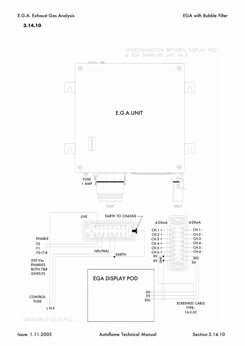
E.G.A. Exhaust Gas Analysis
Issue: 1.11.2005 Autoflame Technical Manual Section 3.14.10
3.14.10
EARTHNEUTRAL
E.G.A.UNIT
EGA DISPLAY POD
FUSE1 AMP
4-20mA
L N E
CONTROLFUSE SCREENED CABLE
TYPE:-16-2-3C
EGA with Bubble Filter
F2F1F3=7-8
ENABLE
220 VacENABLESBOTH 7&8GIVES F3
0V5V
SIG
CH.1 + CH.1 -CH.2 + CH.2 -CH.3 +CH.4 + CH.4 -CH.5 + CH.5 -CH.6 + CH.6 -0V SIG
5VLIN
K
4-20mA
CH.3 -
0V
LIVE EARTH TO CHASSIS

E.G.A. Exhaust Gas Analysis
Issue: 1.11.2005 Autoflame Technical Manual Section
3.14.11 Mk.6 EGA Internal Layout (Shown without cover, for Clinical Waste Applica-tion e.g. O2 & CO Cells only).
3.14.11
EGA with Bubble Filter

E.G.A. Exhaust Gas Analysis
Issue: 1.11.2005 Autoflame Technical Manual Section
3.14.12 General Assembly of Dry Filter
FILTERING MATERIAL (AS SUPPLIED)
FILTER MATERIAL ISPACKED UP TO THE TOP
REDGREEN
SAM
PLE
IN
SAM
PLE
OU
T
SPACE ALLOWS EVENFILTERING OVER TOTAL
SURFACE AREA OF FILTER
N.B. FREE SPACE MUST BE LEFT AT BOTTOM TO STOP ANY PREMATURE BLOCKAGETHE SAMPLE IN & OUT PIPES MUST BE CONNECTED CORRECTLY OR BLOCKAGE
WILL OCCUR WITHIN A FEW HOURS.
3.14.12
EGA with Bubble Filter

E.G.A. Exhaust Gas Analysis
Issue: 1.11.2005 Autoflame Technical Manual Section
3.14.13 General Assembly & exploded view of the Particulate Filter
GLASS OUTER SLEEVE
Pt. no. FILTER1002 FILTER
INTERNAL BODY
OUTLET TUBE
Pt. no. FILTER1001CARTRIDGE
FILTERS
PT No.OR70026 "O" RING
FILTER RETAINING CAP
INLET TUBE
SAMPLE IN
SAM
PLE
OU
T
TOP CAP
ASSEMBLY SHOWNFULL SIZE
PT No.OR70026 "O" RING
3.14.13
EGA with Bubble Filter
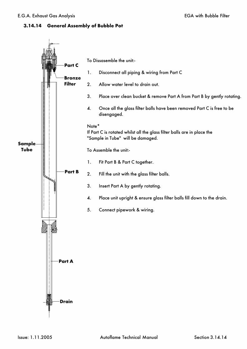
E.G.A. Exhaust Gas Analysis
Issue: 1.11.2005 Autoflame Technical Manual Section
Part A
Part B
Part CTo Dissasemble the unit:-
1. Disconnect all piping & wiring from Part C
2. Allow water level to drain out.
3. Place over clean bucket & remove Part A from Part B by gently rotating.
4. Once all the glass filter balls have been removed Part C is free to bedisengaged.
Note*If Part C is rotated whilst all the glass filter balls are in place the"Sample in Tube" will be damaged.
To Assemble the unit:-
1. Fit Part B & Part C together.
2. Fill the unit with the glass filter balls.
3. Insert Part A by gently rotating.
4. Place unit upright & ensure glass filter balls fill down to the drain.
5. Connect pipework & wiring.
3.14.14 General Assembly of Bubble Pot
SampleTube
Drain
BronzeFilter
3.14.14
EGA with Bubble Filter

E.G.A
. Exhaust Gas A
nalysis
Issue: 1.11.2005A
utoflame Technical M
anualSection
"S" TYPE HIGH TEMPERATURE THERMOCOUPLE ASSEMBLY
WIRING DIAGRAMTYPE "S" SINGLE THERMOCOUPLE
ORANGE +ve
TYPE "S" SINGLE Pt 10%Rh-PtTHERMOCOUPLE
AL23 CERAMIC INSULATOR4mm DIA X 0.8mm TWIN BORE
3/4" NB SCH 40 PIPEMATERIAL:310 STAINLESS STEEL
HOT JUNCTION
WHITE -ve
TERMINAL BLOCK
15mm O/dia X 10mm I/dia TUBEONE END CLOSED
MATERIAL: CERAMIC AL23
40mm PN16 FLANGETO BS 1560
MATERIAL: ASTM A182 F316
CERAMIC CEMENT
EARTH SCREW
CABLE ENTRYM20 X 1.5 THREAD
3/4" BSP PARALLELTHREAD & LOCKNUT
CERAMIC TERMINALBLOCK
CODE H20S - ALUMINIUM ALLOYCONNECTION HEAD
WEATHERPROOF IP68FINISH: EPOXY PAINTED
3.1
4.1
5"S" Ty
pe Therm
oco
uple
3.14.15
EGA
with Bubble Filter
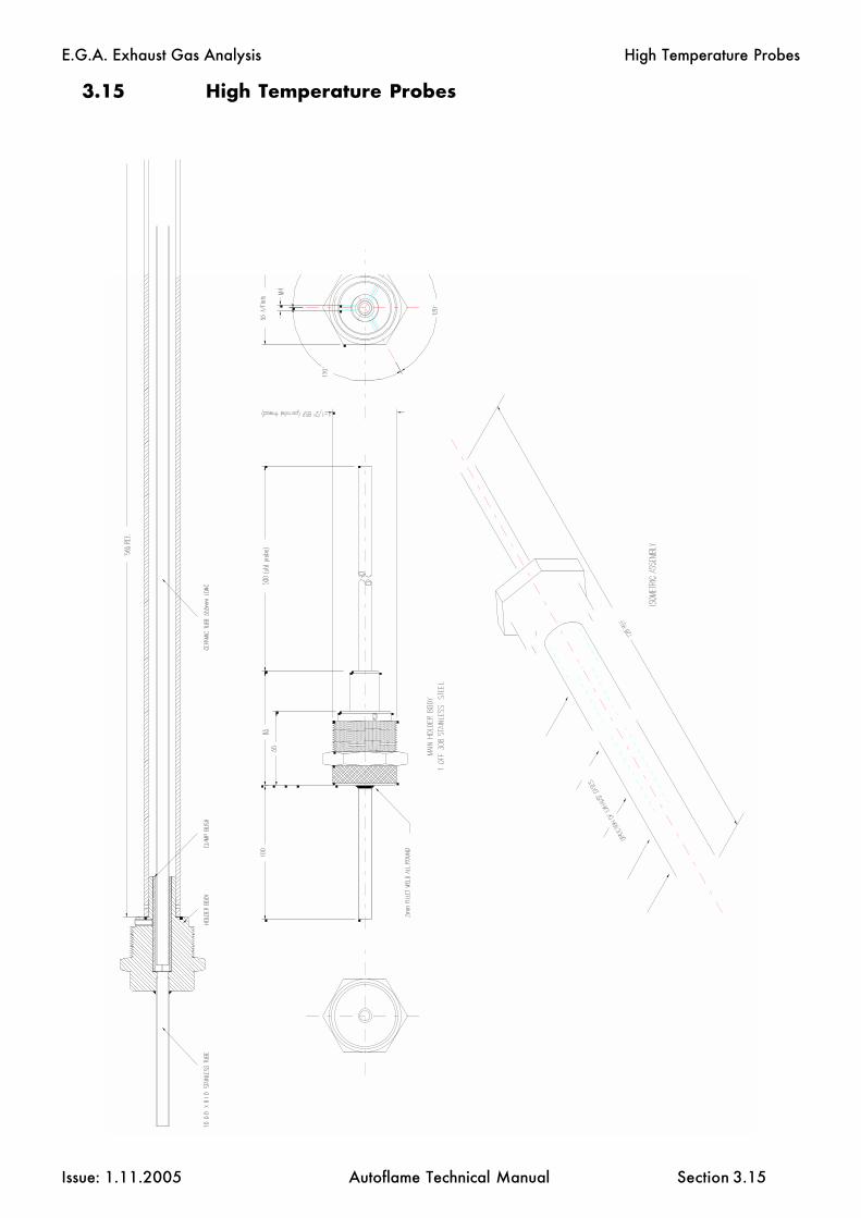
E.G.A. Exhaust Gas Analysis
Issue: 1.11.2005 Autoflame Technical Manual Section
3.15 High Temperature Probes
3.15
High Temperature Probes

E.G.A. Exhaust Gas Analysis
Issue: 1.11.2005 Autoflame Technical Manual Section
3.15.1 Ceramic Sampling Probe Assembly
3.15.1
High Temperature Probes

E.G.A. Exhaust Gas Analysis
Issue: 1.11.2005 Autoflame Technical Manual Section
3.16 Shipping the E.G.A.
3.16
The EGA is a scientific instrument with delicate components. Whenever the EGA is shipped, it isessential that the EGA is packed carefully in an Autoflame EGA shipping carton as originally sup-plied.
Ensure that delivery carriers treat the package appropriately. Label the package as containingdelicate scienctific instrument.
If the EGA is damaged, repair costs will be incurred.
Please contact Autoflame Engineering or your local dealer to obtain a new Autoflame carton.

E.G.A. Exhaust Gas Analysis
Issue: 1.11.2005 Autoflame Technical Manual Section

IBS Intelligent Boiler Sequencing
Issue: 1.11.2005 Autoflame Technical Manual Section
Section 4: I.B.S. Intelligent Boiler Sequencing
4.1 Overview - Features & Benefits of I.B.S. control
4.2 Commissioning and Setting Up Procedure
4.2.1 Guide to Commissioning Sequencing
4.4 Electrical Schematics Showing all Terminal Interconnections
4.4.1 Sequencing Connection Diagram4.4.2 DTI/Sequencing Connection Diagram
4.5 Other Information and Illustrations.
4.5.1 Sequencing Operation4.5.2 Sequencing Combinations4.5.3 Diagram showing Data Transmission/Reception4.5.4 Mini Mk5 Sequencing Status Information
4: Index
123456789012345678901234123456789012345678901234123456789012345678901234123456789012345678901234123456789012345678901234123456789012345678901234123456789012345678901234123456789012345678901234123456789012345678901234123456789012345678901234123456789012345678901234123456789012345678901234123456789012345678901234123456789012345678901234

IBS Intelligent Boiler Sequencing
Issue: 1.11.2005 Autoflame Technical Manual Section
4.1 INTELLIGENT BOILER SEQUENCING (I.B.S.)
Overview of System Operation: Features and Benefits
The Intelligent Boiler Sequencing software, which is included in every M.M. E.G.A. module, furtherextends the application possibilities of the system. The objective of this control form is to ensurethat the minimum number of boiler/burner units are in operation at any one time to satisfy the heatrequirement imposed upon the boiler plant, particularly in the case of multi boiler installations.
There are two variations of I.B.S. software that can be selected by the user via the Options procedure.The first variation relates to heating boilers and the second variation to steam boilers.
Heating Boilers Sequential Control:
A maximum of ten M.M. E.G.A. modules may be interconnected by a two wire screened data cable:(See interconnection drawing). Any string of modules interconnected as detailed can have one ofit’s number designated No. 1 or lead boiler. This identifying of “lead” boiler is achieved by either ofthe following methods:
a) Connecting a mains voltage onto terminal No. 41.b) Instructing the modules via the D.T.I. module (Data Transfer Interface) by software.
Once a “lead” boiler has been selected the system works in the following way:
Typically every five minutes the sequencing software in the lead boiler identifies it’s own firing rate bylooking at the position of the fuel valve in the load index and also the maximum heating capacity ofthe No 1. “lead” boiler. This information would normally be entered when this boiler/burner unitis commissioned. Having established percentage firing rate, and maximum heating capacity, the I.B.S.software calculates the amount of heat being contributed to the system by this boiler. The I.B.S.software in the “lead” M.M. E.G.A. module then contacts in turn each of the modules connected tothis loop and gathers similar information from each. The “lead” module’s I.B.S. software thencalculates the minimum number of boiler/burner units that need to be operational to satisfy the buildingload, imposed upon the plant at that time, and switches the remainder off. There is a terminalconnection on the M.M. E.G.A. module for controlling a two port valve that would normally beinstalled in the boiler’s return pipe connection to the common return header. This facility ensures thatboilers that are switched “off line” do not contribute return temperature water to the flow headerthereby diluting the flow temperature to the building: (See relevant data sheets and drawings showingthe control sequence detailed above).
Example:
There are four boilers interconnected as above, each with a heating capacity of 586kw (2 Mbtu.)In the event of each boiler firing 440kW (1.5 Mbtu) (3/4 of it’s maximum rate), the No. 1 lead boilerwould instruct the No. 4 boiler to shut down and boilers No.s 1, 2 and 3 would adjust their firing rateto maximum. In both cases the boilers are contributing 1758kW (6 Mbtu) to the system but, afterintervention of the I.B.S. sequencing software, three boilers only are carrying the load which is a morefuel efficient method of operation.
If the building load continued to decrease the three boilers would reach a point where they were eachfiring 390kW (1.33 Mbtu) each.
4.1.1

IBS Intelligent Boiler Sequencing
Issue: 1.11.2005 Autoflame Technical Manual Section
At this point the I.B.S. software would switch off the No. 3 boiler as two boilers would be capableof generating the 1172kW (4 Mbtu) required. When the load on the system increases, the reverseprocedure applies, i.e. when, for example, two boilers are firing at near 100% load and the setpointtemperature on either of the modules is not being achieved, the I.B.S. software would switch on a thirdboiler to assist with the generation of the heat requirement. Any boiler can be nominated “lead” boilerby the connection of an input to the appropriate terminal or by a software instruction via the D.T.I.
Steam Boiler Sequential Control:
When the I.B.S. software control package is applied to steam boilers, it’s operation is exactly the sameas above but with the additional features and enhancements as explained in the following.
In the case of heating boilers only two states in the control form exist, either on or off. When steamboiler variation of I.B.S. is optioned there are three states which are controlled sequentially.
The first is “on-line”, this is when the boiler is operating purely under the control of the M.M. E.G.A.module's internal P.I.D. load controller.
The second state is “Standby Warming”: In this case the boiler is operated at a reduced pressuresetpoint, and runs for a number of minutes each hour: e.g. if the on-line boiler or boilers are set at asetpoint of 7 bar (100 p.s.i.) the standby warming boiler controls at a setpoint of 5 bar (72 p.s.i.). Inthis way if the load increases the standby warming boiler can begin to contribute steam quickly. Thereduced setpoint is a user variable option in the same way as the normal control pressure setpoint.The number of minutes run time is also adjustable.
The third state is “off-line”, this is with the burner shut down and the boiler cold. If the load on the boilerhouse increases, this boiler would move into a “warming” condition.
Apart from the variations detailed above, the steam sequencing works in precisely the same way asthe heating boiler sequencing: The sequencing software package ensures that at all times the minimumnumber of boilers are operational to satisfy the load imposed on the boiler house.
Note:
It should be appreciated that all data and control variables can be shown on a screen via the additionof the D.T.I. module to the data loop. The screen and keyboard can be sited locally in the boiler houseor the whole system can be addressed remotely via the normal telecommunications network.In the software in the D.T.I. there is a histogram facility which shows the firing rate and state of eachboiler in the boiler house.
4.1.2

IBS Intelligent Boiler Sequencing
Issue: 1.11.2005 Autoflame Technical Manual Section
4.2.1 GUIDE TO COMMISSIONING SEQUENCING
Before any attempt is made to implement Sequencing operation, it is necessary that the fuel/air positionsand load index are already entered. Refer to Sections 2 or 3 for Commissioning fuel/air positions.
The load index is implemented using the same ten point load index entry method used for the FlowMetering as detailed in Sections 2 and 3 of the manual. If the Flow Metering has already been optionedand the ten point load index entered then it is not necessary to enter this again. However if it is notentered, proceed as detailed below.
1. Set Option 57 to Value 1 (Refer to Section 2.2.4 - Setting Options).
2. Press whilst 57 and 1 are being displayed in the Air and Required windowsrespectively.
3. Next time the burner starts the M.M. will automatically go into the ten point load index entrymode. The firing range is automatically divided into ten equal parts. Each of the ten divisionsfrom high to low has a fuel flow value in whatever unit of flow measurement the user requiresallocated to it. (All extrapolated fuel flow values between the ten points are calculated from a“best fit” mathematical formula).
4. In this mode the window will show fuel value in degrees angular.
The window will be blank.
The window and its associated buttons will be used to enter the
fuel flow in the chosen fuel flow unit per minute value.
Note:
a) The window confirms to the commissioning engineer which of the 10points are currently being measured.
When the positioning motors are moving from one calibrated point to another the
display flashes. When it reaches the next point to be calibrated, with aflow value, the display remains steady.
b) The minimum numerical value for fuel flow that can be entered into memory is 0.01.The maximum numerical value for fuel flow that can be entered into memory is 999.
c) The values are entered in descending order, i.e. Point No.1 is maximum flame andPoint No.10 is at minimum flame.
ENTER
MEMORY
FuelPosition
AirPosition
Required
Actual
Actual
Guide to Commissioning Sequencing
4.2.1.1

IBS Intelligent Boiler Sequencing
Issue: 1.11.2005 Autoflame Technical Manual Section
The 10 sequential points on the load index are allocated automatically by the M.M.
5. When fuel flow has been calculated or read off of a commissioning fuel flow meter the valueis entered as detailed in Point No.4.
The button is then pressed and the flow value is passed into the M.M. memory.
6. The above detailed data entry routine is repeated until all 10 points have flow values allocatedto them.
7. When the last (10th) point has been entered the M.M. stops the burner and implements thecalculations necessary to enable the Load Index to be actioned. Whilst the calculations are beingcarried out a rolling decimal point is displayed.
8. If it is not required to subsequently display the Flow Metering values, set Option 57 back to value0.
9. If implementing "hot water" Sequencing set Options as follows ON EACH M.M.:
Set Option 16 to Value 1 or 3.Set Option 33 to identification number accordingly.Set Option 34 to the rating of burner.Set Option 35 to time between Sequence scans.ENSURE OPTION 53 IS SET TO 0.
10. If implementing "steam" Sequencing set Options as follows ON EACH M.M.:
Set Option 16 to Value 1 or 3.Set Option 33 to identification number accordingly.Set Option 34 to the rating of burner.Set Option 35 to time between Sequence scans.Set Option 53 to the time required for the boiler to be off.Set Option 54 to the time required for the boiler to be on.
Note: Options 53 and 54 are relevant to the "Stand-by Warming" state.Option 53 is the indication to this M.M. that the Sequencing being done is eitherhot water or steam (i.e. 0 - Hot water, non zero value - Steam).
MEMORY
ENTER
Guide to Commissioning Sequencing
4.2.1.2
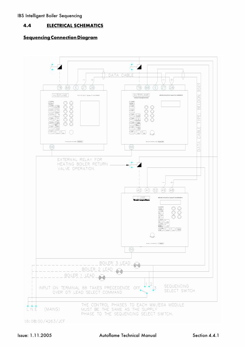
IBS Intelligent Boiler Sequencing
Issue: 1.11.2005 Autoflame Technical Manual Section
MINI Mk.5 M.M./E.G.A. System Pt. No.MMM50016
MEMORY
RUN
E.G.A. M.M.
DISPLAY
STATUS
LOCKOUTRESET
COM
MINI Mk.6 M.M./E.G.A. System Pt. No. MMM60016
METERING
SEQUENCING
CLOSE SCANNERFLAME
OPEN IBS
START FUEL
HIGH
INTER
ENTER
Combustion Management Systems
4.4 ELECTRICAL SCHEMATICS
Sequencing Connection Diagram
4.4.1

IBS Intelligent Boiler Sequencing
Issue: 1.11.2005 Autoflame Technical Manual Section 4.4.2
MINI Mk.5 M.M./E.G.A. System Pt. No.MMM50016
MEMORY
RUN
E.G.A. M.M.
DISPLAYSTATUS
LOCKOUTRESET
COM
MINI Mk.6 M.M./E.G.A. System Pt. No. MMM60016
METERING
SEQUENCING
CLOSE SCANNERFLAME
OPEN IBS
START FUEL
HIGH
INTER
ENTER
Combustion Management Systems
DTI/Sequencing Connection Diagram
If a voltage on terminal 88 is used to select lead boiler, it will take priority over a lead boiler set viathe DTI.

IBS Intelligent Boiler Sequencing
Issue: 1.11.2005 Autoflame Technical Manual Section 4.5.1

IBS Intelligent Boiler Sequencing
Issue: 1.11.2005 Autoflame Technical Manual Section 4.5.2

IBS Intelligent Boiler Sequencing
Issue: 1.11.2005 Autoflame Technical Manual Section 4.5.3
A0
A0
A2
A0
A3
A0
A4
A
0
R0
R
1
A
1R
0R
2 R
0R
3R
0 R
4
R0
R0
A
0
R
1
A1
R0
A
0R
2A
2R
0A
0R
3R
0A
0 R
4 A
4
R0
A
0
A3
Sam
e w
avef
orm
sap
ply
to M
.M. N
o.s
5 to
10.
Dia
gram
sho
win
g Ex
ampl
e of
Dat
a C
omm
unic
atio
ns w
ith R
efer
ence
to F
licke
ring
L.E.
D.s
This
is th
e M
.M. t
hat i
s w
orki
ng c
omm
unic
atio
ns:
Eg.:
- M.M
. No.
1.
This
is a
n M
.M. t
hat i
s no
t wor
king
com
mun
icat
ions
.Eg
.: M
.M. N
o. 3
.
A0
-A
nsw
er fr
om D
.T.I.
A1
-A
nsw
er fr
om M
.M. 1
A2
-A
nsw
er fr
om M
.M. 2
A3
-A
nsw
er fr
om M
.M. 3
A4
-A
nsw
er fr
om M
.M. 4
A5
-A
nsw
er fr
om M
.M. 5
A6
-A
nsw
er fr
om M
.M. 6
A7
-A
nsw
er fr
om M
.M. 7
A8
-A
nsw
er fr
om M
.M. 8
A9
-A
nsw
er fr
om M
.M. 9
A10
-Ans
wer
from
M.M
. 10
R0 -
Requ
est t
o D
.T.I.
R1 -
Requ
est t
o M
.M. 1
R2 -
Requ
est t
o M
.M. 2
R3 -
Requ
est t
o M
.M. 3
R4 -
Requ
est t
o M
.M. 4
R5 -
Requ
est t
o M
.M. 5
R6 -
Requ
est t
o M
.M. 6
R7 -
Requ
est t
o M
.M. 7
R8 -
Requ
est t
o M
.M. 8
R9 -
Requ
est t
o M
.M. 9
R10
- Req
uest
to M
.M. 1
0
Ope
n
Clo
se
Ope
n
Clo
se
Not
e:-
Onl
y 1
M.M
. wor
ksth
e co
mm
unic
atio
ns.
> > > >

IBS Intelligent Boiler Sequencing
Issue: 1.11.2005 Autoflame Technical Manual Section 4.5.4
4.5.4 Mini Mk5 Sequencing Status Information
If parameter 32 = 1 then the information below is displayed instead of the Flow Metering GrandTotal. (Totalising still continues to work in the background).
Sequencing Status Information
Lead Boiler
0 = No Lead Boiler Selected1 to 10 = Number of Lead Boiler
ReceivingSequencing Information
0 = No1 = Yes
CR1Relay Status
0 = Off1 = On
WorkingCommunications/
Sequencing
0 = No1 = Yes
Unused
Status of Input 41
0 = 0V AC 1 = 230V AC
(110V AC)
Disabled Status
0 = Enabled 1 = Disabled
*1
*2
*3
*4
Sequence Code:
Steam
0 On1 Standby/Warming2 Off3 Off
Sequence Code:
Hot Water
OnOffOffOff
*1 *2
*3 *4

IBS Intelligent Boiler Sequencing
Issue: 1.11.2005 Autoflame Technical Manual Section

Water Level Control
Issue: 1.11.2005 Autoflame Technical Manual Section
Mk6 Evolution
5.1 Introduction
5.1.1 Water Level System Schematic5.1.2 Method of Operation and Control Philosophy5.1.3 Movement Detection of Water5.1.4 Swell Management
5.2 “2nd Low” Switching Philosophy
5.3 Bottom Blowdown/External Probe Chamber Blowdown Management
5.4 Historical Alarm Record
5.5 First Out Annunciation
5.6 Integration of External Water Level Controls
5.7 Steam Flow Metering
5.7.1 Steam Flow Metering Incorporating a Deaerator5.7.2 Calculation of Steam Flow Metering for Multiple Boilers
with Deaerators5.7.3 Schematic for Steam Flow Application with a Deaerator5.7.4 Schematic for Steam Flow Application without a Deaerator
5.8 Heat Flow and Hot Water Flow Metering
5.8.1 Calculation of Heat Output and Volume Flow5.8.2 Schematic for Heat Flow Metering Application
5.9 Technical Data Sheets (to assist in understanding and applying the system)
5.9.1 Wave Signature Explanation5.9.1.1 Breaking Bubble/Spray5.9.1.2 Thermal Currents (heat energy in water)5.9.1.3 Steam Flow Induced Surge5.9.1.4 Foaming
5.9.2 Schematic Explanation of Water Level Probes5.9.3 Schematic of the Probe Sampling Hardware5.9.4 Capacitance Probe Operation5.9.5 Capacitance Probe- General Installation Information5.9.6 Capacitance Probe- External Mounted Pots5.9.7 Capacitance Probe- Internally Mounted Probes5.9.8 Capacitance Probe- Water Tube Boiler5.9.9 External Probe Chamber Dimensions5.9.10 Capacitance Probe and Feed Water Valve Details
5: Index
Section 5: Water Level Control and T.D.S. Management

Water Level Control
Issue: 1.11.2005 Autoflame Technical Manual Section
Mk6 Evolution
5.10 Commissioning and Set-up Procedure
5.10.1 Water Level Set-ups5.10.2 Diagnostics Screens5.10.3 Replacing the Servo Motor on a Feed Water Valve5.10.4 Commissioning the Water Level Positions
5.10.4.1 Commissioning Screens5.10.4.2 Expansion PCB Connection Terminals5.10.4.3 Capacitance Probe Connections
5.10.5 Operational Checks5.10.6 Terminal Descriptions5.10.7 Electrical Specification5.10.8 Fuse Position/Rating5.10.9 Pre-alarm Display
5.11 Normal Operation
5.11.1 End User Day to Day Operation5.11.2 Water Level Operation5.11.3 First Out Status5.11.4 Key to Alarms
5.12 Surface Blowdown/T.D.S. (Total Dissolved Solids) Management
5.12.1 Philosophy of the T.D.S. Control System5.12.2 T.D.S. Calibration (User Calibration Method)5.12.3 T.D.S. Calibration (Automatic Internal Calibration Method)5.12.4 Control and Management of T.D.S. in a Steam Boiler5.12.5 Installation of the T.D.S. Probe Assembly
5.12.5.1 Vertically Mounted5.12.5.2 Horizontally Mounted
5.12.6 Schematic Detail of the Measurement and Sample Routine5.12.7 Relationship between Conductivity, Temperature and
T.D.S. values5.12.8 Schematic of the T.D.S. Probe and Sampling Vessel5.12.9 Top Blowdown Management Set-Up and User Guide
5.12.9.1 Top Blowdown Management5.12.9.2 Adjustment of the T.D.S. Target value5.12.9.3 T.D.S. Probe Calibration5.12.9.4 Top Blowdown Adjusters5.12.9.5 Top Blowdown Adjusters Settings and Values5.12.9.6 T.D.S. Timing Diagram
Section 5: Water Level Control And T.D.S. Management
5: Index

Water Level C
ontrol
Issue: 1.11.2005A
utoflame Technical M
anualSection
Mk6 Evolution
5.1.1
5.1
.1W
ater Level Sy
stem Schem
atic
Water Level System
Schematic
BOILER
FLUE
T.D.S.PROBE
FEEDWATERVALVE
STEAMSENSOR
CAPACITANCEPROBES
TEMP.SENSOR
TEMP.SENSOR
SURFACEBLOWDOWN
BOTTOMBLOWDOWN
FEEDWATERSERVO
FEEDWATERPUMP
EXTERNALPROBE
CHAMBER
OPTIONAL VSD IN PLACEOF FEED WATER VALVE

Water Level Control
Issue: 1.11.2005 Autoflame Technical Manual Section
Mk6 Evolution
The Autoflame level control is probably the safest and most accurate method of controlling waterlevel in a steam boiler.
The system has a typical level control accuracy of + or – 2mm in still water. This accuracy is main-tained during normal operation by Autoflame’s patented “wave signature and turbulence manage-ment” software.
The system safety is guaranteed as the level measurement is managed by two identical capacitanceprobes both of which measure and control to the level switching points entered at the time ofcommissioning.
Both probes control typically “high level”, “required level”, “first low” and “second low”. The levelreading from both probes are constantly compared and checked against each other and the commis-sioned data. When controlling required level this data stream is combined with a PI algorithmwhich controls either the two port feedwater control valve or the variable speed drive to the feedpump. Each probe is self checked for electrical and mechanical integrity by hardware referencesand self checking software routines. Each probe and its control electronics are compensated forambient temperature variations and component drift. It can be seen that this methodology guaran-tees absolute safety of operation.
By our method the probes control the required level by sampling and learning wave signature andof the turbulence within the boiler shell. This “wave signature management” takes into account thechanges in burner firing rate and any variance in pressure in the boiler shell. Incorporated withinthe system hardware are all necessary electronic switching functions to control audible alarms,mute/reset and indication lights required to meet standard North American and European codes.Safety, accuracy and integrity are guaranteed.
5.1.3 Movement Detection Of Water
When the burner is running it is expected that a wave turbulence signature of in excess of 20Hz / 1mmwill always be present (due to vibration of thermal energy). Both probes are checked for this value.The default setting is 20Hz, a range of 0-100Hz is possible, if set to ‘0’ this feature is turned off. Thisfeature ensures that either probe cannot read a still water condition when the burner is running. Thissafety check ensures no static or stuck value can be accepted (i.e probes are being checked that theyare in water).
5.1.4 Swell Management
When there is a sudden drop in boiler pressure an increase in water level will be observed. This is dueto the steam bubbles in the water expanding and so increasing the water level. It follows that thewater feed would then turn off or to a low flow condition. The Autoflame system identifies this ambigu-ous condition and increases the “required water level” by up to 50% of the distance between normal“required level” and “high water level”. When normal conditions are reinstated “required level”returns to the normal setting. This stops spurious shut downs due to 1st low being switched duringthese transient conditions. The Autoflame system knows what the firing rate and boiler pressure is atany one time and uses this information to identify the above condition. This system is the only waterlevel control in the world that can do this, this feature is one of the main elements in the patent claim.
5.1.2 Method Of Operation & Control Philosophy
5.1.2
Introduction
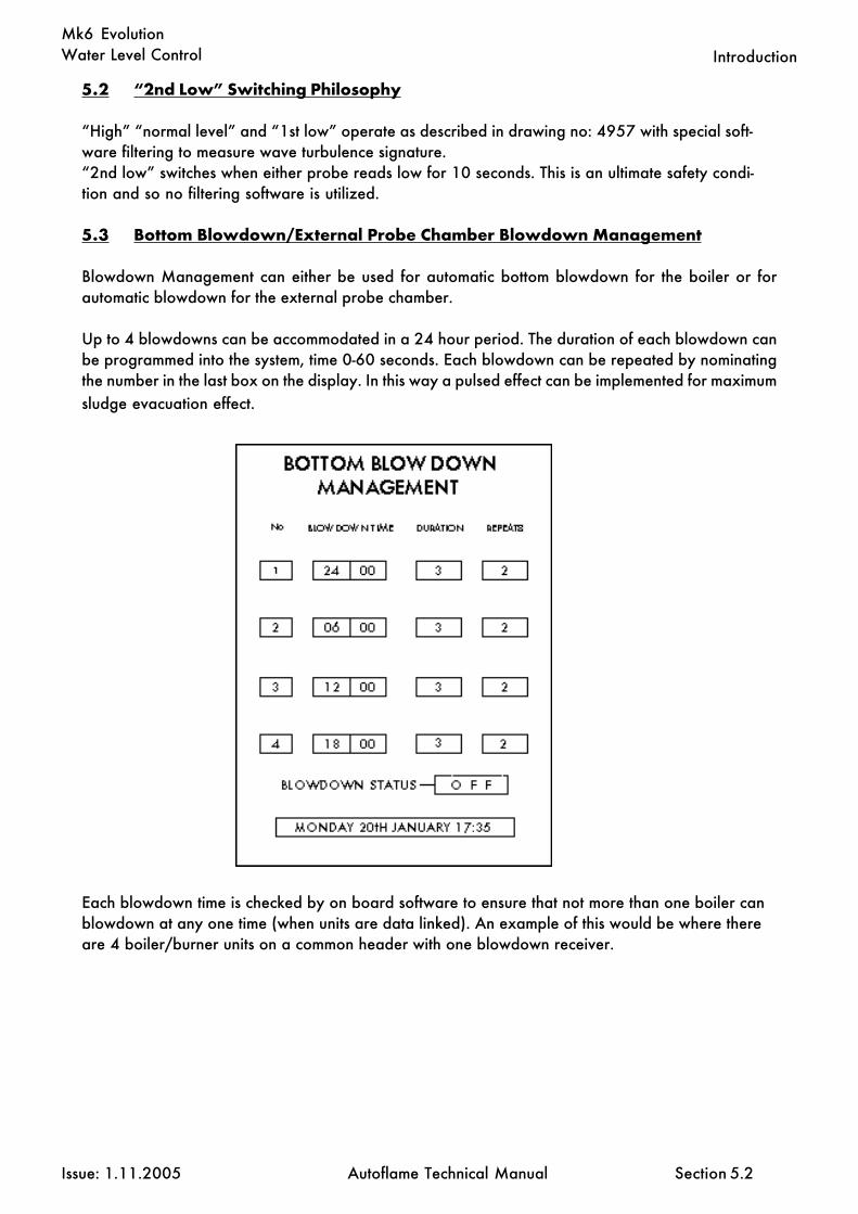
Water Level Control
Issue: 1.11.2005 Autoflame Technical Manual Section
Mk6 Evolution
5.2 “2nd Low” Switching Philosophy
“High” “normal level” and “1st low” operate as described in drawing no: 4957 with special soft-ware filtering to measure wave turbulence signature.“2nd low” switches when either probe reads low for 10 seconds. This is an ultimate safety condi-tion and so no filtering software is utilized.
5.3 Bottom Blowdown/External Probe Chamber Blowdown Management
Blowdown Management can either be used for automatic bottom blowdown for the boiler or forautomatic blowdown for the external probe chamber.
Up to 4 blowdowns can be accommodated in a 24 hour period. The duration of each blowdown canbe programmed into the system, time 0-60 seconds. Each blowdown can be repeated by nominatingthe number in the last box on the display. In this way a pulsed effect can be implemented for maximumsludge evacuation effect.
5.2
Each blowdown time is checked by on board software to ensure that not more than one boiler canblowdown at any one time (when units are data linked). An example of this would be where thereare 4 boiler/burner units on a common header with one blowdown receiver.
Introduction

Water Level Control
Issue: 1.11.2005 Autoflame Technical Manual Section
Mk6 Evolution
5.4 Historical Record Of Events On Autoflame Water Level Control
Within the system there are four dedicated screens for the recording of events relating to water levelcontrol & management of the boiler.Each event is tagged for time, date and the type of incident, i.e high water, 1st low 2nd low andlockout.
Each screen will give details of four events, therefore the last 16 events will be kept in memory. Thisinformation can be accessed , monitored and logged via the D.T.I data transfer package.
5.4
Introduction

Water Level Control
Issue: 1.11.2005 Autoflame Technical Manual Section
Mk6 Evolution
5.5 First Out Annunciation
When the control circuit has a long series chain of various thermostat and switching elements, it issometimes difficult to identify which element has opened the control circuit (see schematic detailunder).
The First Out Annunciation can be set in any of the following ways:Disabled- First Out does not appear on the MM screen (not in use).Displayed- First Out status is viewed on the MM screen. The burner will continue to operateif a First Out fails.Enabled- First Out status is viewed on the MM screen. In the event of a First Out the burnerwill shutdown until the error is corrected.
5.5
Introduction
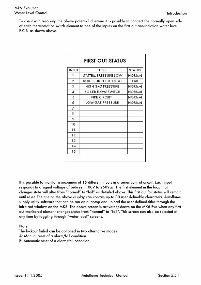
Water Level Control
Issue: 1.11.2005 Autoflame Technical Manual Section
Mk6 Evolution
To assist with resolving the above potential dilemma it is possible to connect the normally open sideof each thermostat or switch element to one of the inputs on the first out annunciation water levelP.C.B. as shown above.
It is possible to monitor a maximum of 15 different inputs in a series control circuit. Each inputresponds to a signal voltage of between 100V to 250Vac. The first element in the loop thatchanges state will alter from “normal” to “fail” as detailed above. This first out fail status will remainuntil reset. The title on the above display can contain up to 30 user definable characters. Autoflamesupply utility software that can be run on a laptop and upload the user defined titles through theinfra red window on the MK6. The above screen is activated/shown on the MK6 Evo when any firstout monitored element changes status from “normal” to “fail”. This screen can also be selected atany time by toggling through “water level” screens.
Note:The lockout failed can be optioned in two alternative modesA: Manual reset of a alarm/fail conditionB: Automatic reset of a alarm/fail condition
5.5.1
Introduction

Water Level Control
Issue: 1.11.2005 Autoflame Technical Manual Section
Mk6 Evolution
5.5.2 Procedure for wiring First Out Annunciator.
The below diagram shows the correct procedure for wiring a field device to the Autoflame First OutAnnunciator. The switch required is a double throw contact, this is one with a Common (c), Nor-mally Closed (nc) and Normally Open (no) contacts. Figure 1 shows the devise being a gas pres-sure switch, announced on MA1.
Fig 1. Switch shown in a failed condition.
Fig 2. Alarm input shown inverse condition i.e. voltage input signal removed.
5.5.2
Introduction
FO1
FO1

Water Level Control
Issue: 1.11.2005 Autoflame Technical Manual Section
Mk6 Evolution
5.6 Ability To Integrate Other Water Level Controls Into The Autoflame System
As a confidence building exercise it is sometimes requested by a client that he would also like toretain his old float type level controls as a “belt & braces” solution. Autoflame have allocated 3terminals to accommodate “high”, “1st low” and “2nd low”. This is a user selectable facility whichcan be accessed by the water level “SETUPS” in the MK6 Evo. Shown below is the connectionschematic which shows how this can be implemented if required.
Example of non Autoflame level control elements being incorporated into the Autoflame WaterLevel Control System.
5.6
Introduction

Water Level Control
Issue: 1.11.2005 Autoflame Technical Manual Section
Mk6 Evolution
5.7 Steam Flow Metering
Steam flow metering is a very commercially attractive capability that exists within the Autoflamelevel control package. By the addition of two temperature detectors it is possible to extrapolateaccurately steam flow from a boiler both as an instantaneous value and a totalized amount overtime. This means that by the addition in price of two temperature sensors the end client can beoffered the benefit of a full steam flow metering package. An explanation of how this is achieved isdetailed below.
From Fuel Flow Metering it can be seen that the fuel gross calorific heat input is 24.5 million BTU/hr(example).
Therefore 24,500,00 BTU/hr (gross fuel calorific value)less 245,000 BTU/hr (1% loss standing losses)less 4,365,900 BTU/hr (18% stack loss E.G.A)equals 19,889,100 BTU/hr (net calorific value of the fuel into the wet side of the boiler).
5.7
Steam Flow Metering

Water Level Control
Issue: 1.11.2005 Autoflame Technical Manual Section
Mk6 Evolution
From Steam Flow Metering it is possible to calculate the amount of heat necessary to raise 1lb ofwater from 180 degrees F (feed water temp) to 85 p.s.i G steam at 327 degrees F. From standardsteam tables held in memory the amount of heat required is calculated to be 1040 BTU. This figureis the latent heat of liquid into steam (gas) plus the sensible heat components.Note feed water temperature and steam temperature are measured by the systems temperaturesensors.
19,889,100 BTU = 19,124 lb/hr1040 BTU/hr of steam
If blow down losses are calculated to be 3% (example) the system allows this correction to beentered.
19,124 x 0.97 = 18,550 lbs/hr Steam Flow.
Instantaneous values are calculated using the above. Totalized values for steam flow use the samemechanism but sample values are taken every 5 seconds and integrated over the run time of theboiler burner system.
5.7
Steam Flow Metering

Water Level Control
Issue: 1.11.2005 Autoflame Technical Manual Section
Mk6 Evolution
5.7.1.1 Steam Flow Metering Incorporating a Deaerator
A common practice in steam generation is the use of a “deaerator” to remove the oxygen from thefeed water and hence reduce the incidence of oxygen corrosion in the boiler, steam & condensatepipe work.
The principle of a deaerator is to mix the make-up water with the condensate return and live steamdirect from the boiler in a tank. Flash steam may also be directed back to the tank. The effect is tomechanically “scrub” the oxygen from the feed water and also to preheat it before it is pumped tothe boiler.
In the system as set out above it is no longer valid to measure the temperature of the feed water justbefore it enters the boiler as the inlet temperature for the “steam meter” calculation. This water hasalready been preheated by steam from the boiler and therefore this additional energy should not betaken into the software calculation.
The solution is to treat the boiler and deaerator as one system. The energy into the system is sup-plied by the burner and the inlet temperature is the “weighted average” of the condensate returntemperature and makeup water temperature. The outlet steam temperature is measured by a tem-perature sensor in exactly the same way as in a system without a deaerator.
5.7.1.1
Steam Flow Metering

Water Level Control
Issue: 1.11.2005 Autoflame Technical Manual Section
Mk6 Evolution
5.7.1.2 Steam Flow Measurement For Multi Boilers With Steam Deaerators
1) A flow meter is fitted into the condensate return and into the cold water makeup pipe-lines. A PT1000 temperature detector is fitted into both condensate and cold water make up pipe-lines (T1 & T1A).
2) Each flow meter has a 4-20mA output. In each case 4mA equals ‘0’ gallons per minuteor litres per second, 20mA equals the maximum range of the meter. The maximum range must beentered into the MK6 Evo via setup options (GPM or L/sec)
3) From the information /data collected as in ‘2’ the “weighted” temperature of the feedwater to the boilers can be calculated. The “weighted” temperature of the feed water is distributedto each of the MK6 Evo’s (as in our example dwg no: 5211). The weighted temperature is sentdigitally via the RS485 data transmission line to each MM MK6 Evo (terminals 27 & 28).
4) Each Water Level P.C.B. has its own steam temperature sensor mounted at the steamoutlet on each boiler (T2) see dwg no: 5211.
5) It is important that the No:1 MK6 Evo with Water Level P.C.B. is not powered down asthe data transmission would ‘stop’. If the No:1 is switched off out of necessity then the default“weighted” value temperature entered at the time of commissioning would be used until the No:1and its data transmission were reinstated. In this way maximum accuracy in the steam flow ratecalculation can be guaranteed.
When “Imperial” units are selected (US spec) the following units of measurement are used:
Steam Flow = lb/hrLiquid Flow = U.S. Gallons/minTemperature = Degrees FHeat Flow = BTU/hrHeat = BTU
When “Metric” units are selected (Euro spec) the following units of measurement are used:
Steam Flow = Kg/hrLiquid Flow = Litres/secTemperature = Degrees CHeat Flow = MWHeat = KJ
5.7.1.2
Steam Flow Metering

Water Level Control
Issue: 1.11.2005 Autoflame Technical Manual Section
Mk6 Evolution
5.7.2 Steam Flow Metering Incorporating a Deaerator, Calculations
1: First the percentage “Make up“ in the “Feed water” must be calculated.
Where %Mu = % Cold make up waterV1 = Volume of condensate return waterV2 = Volume of cold make up water
%Mu = 100 x V2 (V2 + V1)
Example: 1Steam boiler with a volume of condensate return at 40 GPM and make up water at 8 GPM
Make up % = 100 x 8 = 16.7% (8 + 40)
2: To calculate the second part to establish the “Weighted Average Temperature” the followingequation is used.
Where T ave = Weighted Average temperatureT1A = Temperature of condensateT1 = Temperature of make up water%Mu = Percentage of make up water
T ave = T1A – (%Mu x (T1A – T1)) 100
Example: 2Steam boiler with condensate return temperature of 176°F and a make up water temperature of41°F . From the above example (1) the make up percentage is 16.7%
Weighted average = 176 – (16.7 x (176 – 41)) = 153.4°F 100
To implement the above control form the following calculations have been imbedded in the revisedsoftware to obtain the “Weighted Average Temperature” (T ave).
5.7.2
Steam Flow Metering

Water Level Control
Issue: 1.11.2005 Autoflame Technical Manual Section
Mk6 Evolution
5.7.3
5.7.3 Schematic For Steam Flow Application With A Deaerator
Steam Flow Metering

Water Level Control
Issue: 1.11.2005 Autoflame Technical Manual Section
Mk6 Evolution
5.7.4
5.7.4 Schematic For Steam Flow Application Without A Deaerator
Steam Flow Metering
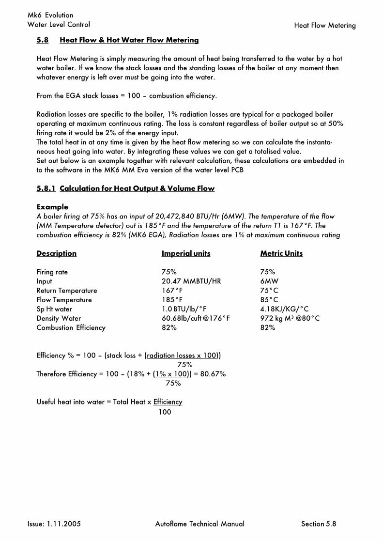
Water Level Control
Issue: 1.11.2005 Autoflame Technical Manual Section
Mk6 Evolution
5.8 Heat Flow & Hot Water Flow Metering
Heat Flow Metering is simply measuring the amount of heat being transferred to the water by a hotwater boiler. If we know the stack losses and the standing losses of the boiler at any moment thenwhatever energy is left over must be going into the water.
From the EGA stack losses = 100 – combustion efficiency.
Radiation losses are specific to the boiler, 1% radiation losses are typical for a packaged boileroperating at maximum continuous rating. The loss is constant regardless of boiler output so at 50%firing rate it would be 2% of the energy input.The total heat in at any time is given by the heat flow metering so we can calculate the instanta-neous heat going into water. By integrating these values we can get a totalised value.Set out below is an example together with relevant calculation, these calculations are embedded into the software in the MK6 MM Evo version of the water level PCB
5.8.1 Calculation for Heat Output & Volume Flow
ExampleA boiler firing at 75% has an input of 20,472,840 BTU/Hr (6MW). The temperature of the flow(MM Temperature detector) out is 185°F and the temperature of the return T1 is 167°F. Thecombustion efficiency is 82% (MK6 EGA), Radiation losses are 1% at maximum continuous rating
Description Imperial units Metric Units
Firing rate 75% 75%Input 20.47 MMBTU/HR 6MWReturn Temperature 167°F 75°CFlow Temperature 185°F 85°CSp Ht water 1.0 BTU/lb/°F 4.18KJ/KG/°CDensity Water 60.68lb/cuft @176°F 972 kg M³ @80°CCombustion Efficiency 82% 82%
Efficiency % = 100 – (stack loss + (radiation losses x 100)) 75%Therefore Efficiency = 100 – (18% + (1% x 100)) = 80.67% 75%
Useful heat into water = Total Heat x Efficiency 100
5.8
Heat Flow Metering

Water Level Control
Issue: 1.11.2005 Autoflame Technical Manual Section
Mk6 Evolution
5.8.1 Heat Flow & Hot Water Flow Metering
Therefore U.H.W = 20,472,840 x 80.67 = 16,515,440 BTU Hr 100
Volume Flow in lbs hr = Useful heat M BTU Hr SP Ht BTU /lb/°F x (Flow Temp – Return Temp)
Therefore lbs hr = 16,515,440 = 917,397 lb Hr 1 x (185 – 167)
Note: - Density of water at 176°F = 60.68lbs cu ft
Therefore Cu ft Hr = 917,397 = 15,118 cu ft Hr 60.68
Note: - 1 cu ft Hr = 0.124676 US G.P.M
Therefore 15118 x 0.124676 = 1884.85 US G.P.M
Volume flow in US G.P.M = 1884.85
It can be seen from the above that by adding the water level P.C.B and a return temperature detec-tor to the MK6 system that you get the following additional useful information.
“Useful heat into water” (BTU/hr) &“Volume flow” (US G.P.M)
This is displayed on the screen of the MK6 EVO.
The direct benefit is that you have a “Heat meter” and “Flow meter” for any hot water boiler.
5.8.1
Heat Flow Metering

Water Level Control
Issue: 1.11.2005 Autoflame Technical Manual Section
Mk6 Evolution
5.8.2
5.8.2 Schematic For Heat Flow Metering Application
Heat Flow Metering

Water Level Control
Issue: 1.11.2005 Autoflame Technical Manual Section
Mk6 Evolution
5.9.1 Wave Signature Explanation
Wave signature in a boiler is a combination of the following main components.
5.9.1.1 Breaking Bubble/Spray
Bubbles of steam breaking at the boiler water level surface. These precipitate little droplets as sprayseveral inches above the water surface in an upwards direction.
The droplets tend to coat the surface of the level probe which in turn will read as an increase in thewater level. This situation is largely avoided by fitting anti surge pots inside the boiler shell (seesection 5.9.7).When the probes are fitted externally to the boiler shell this situation can not arise (see section5.9.9).
5.9.1.2 Thermal Currents (heat energy in water)
Many bubbles breaking simultaneously and thermal currents from the furnace tube and 2nd, 3rd,4th pass smoke tube create their own turbulence/wave signature on the surface of the water. Thetypical result is short choppy/peaky wave patterns as below.
Surface tension of bubblebursts releasing droplets.
5.9.1
A second set of turbulence is the wave reflections off the sides of the boiler. The whole of the aboveis largely attenuated away by mounting the probes externally to the main boiler shell in a separatepot or pots (see section 5.9.9)
Technical Data Sheets: Wave Signature Explanation
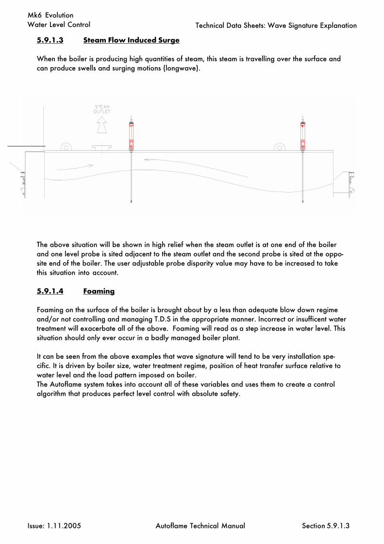
Water Level Control
Issue: 1.11.2005 Autoflame Technical Manual Section
Mk6 Evolution
5.9.1.3 Steam Flow Induced Surge
When the boiler is producing high quantities of steam, this steam is travelling over the surface andcan produce swells and surging motions (longwave).
The above situation will be shown in high relief when the steam outlet is at one end of the boilerand one level probe is sited adjacent to the steam outlet and the second probe is sited at the oppo-site end of the boiler. The user adjustable probe disparity value may have to be increased to takethis situation into account.
5.9.1.4 Foaming
Foaming on the surface of the boiler is brought about by a less than adequate blow down regimeand/or not controlling and managing T.D.S in the appropriate manner. Incorrect or insufficent watertreatment will exacerbate all of the above. Foaming will read as a step increase in water level. Thissituation should only ever occur in a badly managed boiler plant.
It can be seen from the above examples that wave signature will tend to be very installation spe-cific. It is driven by boiler size, water treatment regime, position of heat transfer surface relative towater level and the load pattern imposed on boiler.The Autoflame system takes into account all of these variables and uses them to create a controlalgorithm that produces perfect level control with absolute safety.
5.9.1.3
Technical Data Sheets: Wave Signature Explanation

Water Level Control
Issue: 1.11.2005 Autoflame Technical Manual Section
Mk6 Evolution
5.9.3
5.9.3 Schematic Of The Probe Sampling Hardware
Technical Data Sheets
REED
REL
AY
PRO
CES
SOR
TEM
PERA
TURE
SEN
SOR
ON
P.C
.B.
E.G
.A.
M.M
.
CLO
SE
RUN
CO
M
FLA
ME
SCA
NN
ER
RESE
TLO
CK
OU
T
STA
TUS
DIS
PLA
Y
Com
bust
ion
Man
agem
ent S
yste
ms
FUEL
HIG
H
SEQ
UEN
CIN
G
STA
RT
OPE
N
MET
ERIN
G
IBS
AIR
SEN
SOR
V.S
.D.
ENTE
R
INTE
R
MEM
ORY
MU
TE&
RES
ET
CO
MPE
NSA
TIO
N
TEM
PO
UTS
IDE
LEVE
LW
ATE
R
A -
DC
ON
VER
TOR
RS 4
85C
OM
MU
NIC
ATI
ON
LIN
K
REFE
REN
CE
CA
PAC
ITO
RN
ETW
ORK

Water Level Control
Issue: 1.11.2005 Autoflame Technical Manual Section
Mk6 Evolution
5.9.4 Capacitance Probe Operation
Variations in the capacitance effect the frequency of the signal response to AC signal.
Stainless SteelPTFE
Water
Water is earthed. This is part of the regulations,ensuring the boiler vessel must be earthed.
Capacitative area- through PTFE
As the water level drops, the capacitance drops and the frequency increases.As the water level rises, the capacitance increases and the freauency decreases.
With the water level system, very small capacitances are recorded (~10-20pF)
The numbers shown at the top of the probes during commissioning repesent the frequency (Hz),approximately 40,000 depending on probe length.
Over time, the circuit will drift with temperature change and long term drift (this is the change due totime). This is accounted for in the Autoflame system, by the following procedures:
• A temperature sensor on the circuit board corrects for variation in temperature andsubsequent frequency changes. This sensor on the PCB changes the input into the microprocessor.
• A reference capacitor has a frequency of 60,000 Hz nominal (+/- 2000 Hz). If whenthe reference capacitor is switched on , the value is out of this range then the system will show a TCerror. This reference capacitor has negligible long term drift and is quoted as drift-free (thiscapacitor can drift by as much as 1500 by default. This is set within the water level parameter C.1. TCerror then displayed). During commissioning, the system notes the temperature, the frequency and thereference capacitor value (the reference value measured in the last minute) when each point is added.The reference value is checked once every 60 seconds (the signal moves away from the workingcapacitor to the reference capacitor). During operation, the system uses the storedreference value (at each point) to correct for long term drift in the signal coming off the probe, i.e.
• Control point- 41500• If reference 59500, drifts to 59200 (change of 0.05%)• Then the control point decreases by 0.05%
Note: although reference capacitor will not drift the, the electronics can and the system would correctthe control point by this 0.05%. The value is corrected by percentage, not actual value!
Water
5.9.4
Technical Data Sheets

Water Level Control
Issue: 1.11.2005 Autoflame Technical Manual Section
Mk6 Evolution
Red Blue Green Yellow
Power Communication
The probe head is rated for 0-700C (ambient temperature of air around boiler).The electronics are rated for 0-850C.The boiler must be insulated, or the radiated temperature will create problems.Capacitance probe rating- IP68.
The reference frequency will drop as the temperature rises (50Hz per 0C).For every 1mm change in the water level, the frequency will change by 20Hz.
Swell management takes care of many variations between commissioned level and every dayvalues.
5.1.1
Technical Data Sheets

Water Level Control
Issue: 1.11.2005 Autoflame Technical Manual Section
Mk6 Evolution
5.9.5
5.9.5 Capacitance Probe- General Installation Information
Technical Data Sheets

Water Level Control
Issue: 1.11.2005 Autoflame Technical Manual Section
Mk6 Evolution
5.9.6
5.9.6 Capacitance Probe- Externally Mounted Pots
Technical Data Sheets

Water Level Control
Issue: 1.11.2005 Autoflame Technical Manual Section
Mk6 Evolution
5.9.7
5.9.7 Capacitance Probe- Internally Mounted Probes
Technical Data Sheets
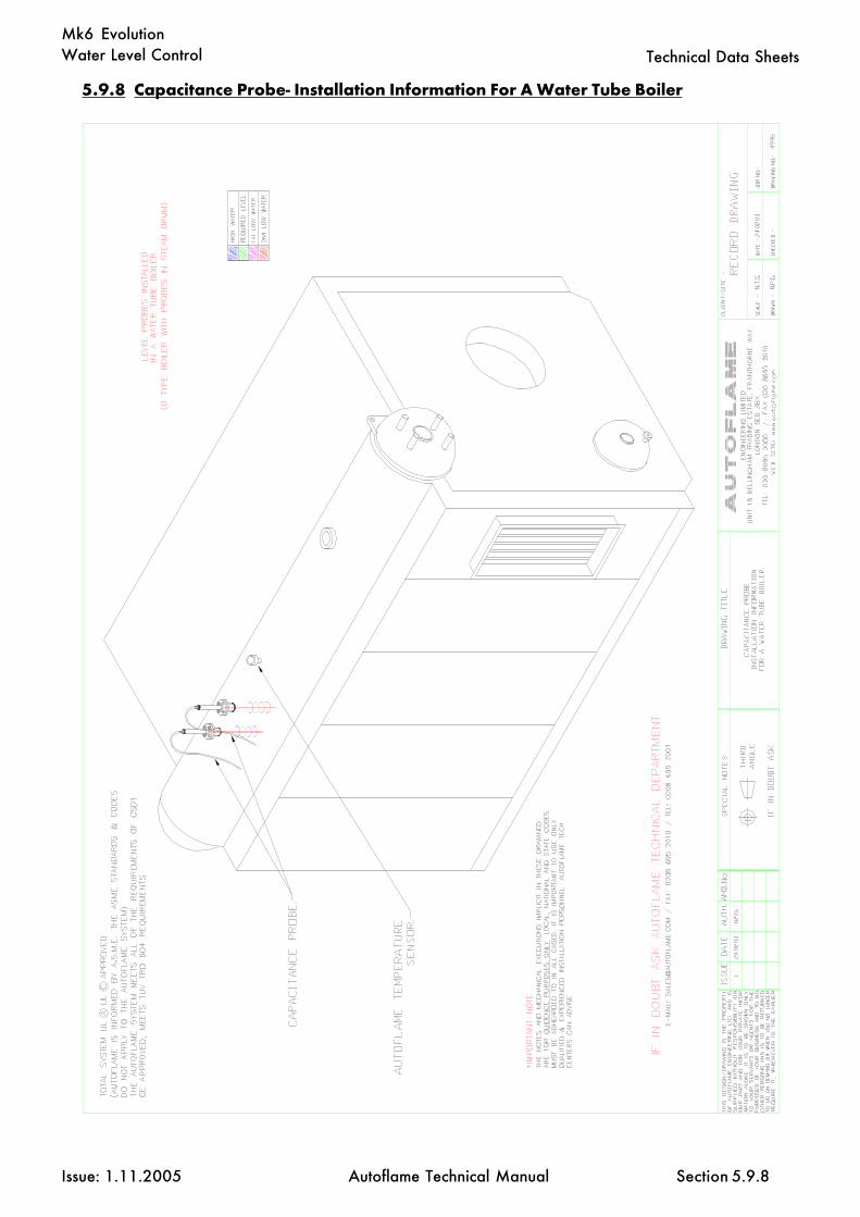
Water Level Control
Issue: 1.11.2005 Autoflame Technical Manual Section
Mk6 Evolution
5.9.8
5.9.8 Capacitance Probe- Installation Information For A Water Tube Boiler
Technical Data Sheets

Water Level Control
Issue: 1.11.2005 Autoflame Technical Manual Section
Mk6 Evolution
5.9.9
5.9.9 External Probe Chamber Dimensions
Technical Data Sheets

Water Level Control
Issue: 1.11.2005 Autoflame Technical Manual Section
Mk6 Evolution
5.9.10
5.9.10 Capacitance Probe and Feed Water Valve Details
Technical Data Sheets
Feed Water Valve
Valve sizes: ½” to 2”Carbon steel valve, stainless steelball & stemServo Torque: 37ft.IbNEMA 4 ratedPosition feed back potentiometerFlange spec: ANSI 300IbMaximum pressure: 300psiMaximum volume: 11,000gal/hr
Capacitance Probes
Probe connection: ½”Probe length: 20” - 60”Stainless SteelPTFE coated

Water Level Control
Issue: 1.11.2005 Autoflame Technical Manual Section
Mk6 Evolution
5.9.11
5.9.11 Capacitance Probe Assembly Drawing
Technical Data Sheets

Water Level Control
Issue: 1.11.2005 Autoflame Technical Manual Section
Mk6 Evolution
5.10 Water Level Setups
To Select Water Level Setups Mode(Note: Ch1, Ch2, Ch3, Ch4, Ch5 and Ch6 refer to the rows of buttons respectivelystarting with Ch1 at the top)
Water level setup values can be changed by entering the water level setup mode. The password mustfirst be entered.To enter the password follow the steps listed:
Either deselect and then select fuel, or power down and then up.
If system is already commissioned, press before the COM L.E.D. stops flashing.
If system is not already commissioned, commissioning mode will be set automatically.
“ENTER PASSWORD” is displayed.
Use the Ch1 and Ch2 to set the Password codes. Then press
“SYSTEM ACTIVATE, WATER LEVEL CONFIGURE” is displayed.
On this additional password screen, it is necessary to set both Ch1 and Ch3. These are both set to #3if the Autoflame water level system is to be active. Alternatively, these are both set to #7 for Mk6standard use without the water level system. It is also necessary to set the Ch5 value for First OutAnnunciation. Set this to #0 to disable the First Out Annunciation, #1 to display the First OutAnnunciation (but not to lock out) and to #2 to enable the First Out Annunciation, i.e. First Out locks out.
Then press
The WATER LEVEL and CLOSE lights will flash.
To enter water level commissioning press
To enter water level setups press the Ch6 simultaneously.
To select a setup use the Ch2 buttons.
To change the setups value use the Ch3 buttons.
Any number of water level setup values can be changed when in this mode.
When changes have been made press
All new Water Level Setup values are then permanently stored.
COM
CLOSE
5.10
Commissioning and Setting up Procedure: Water Level Setups
WATERLEVEL
ENTER
MEMORY
ENTER
MEMORY
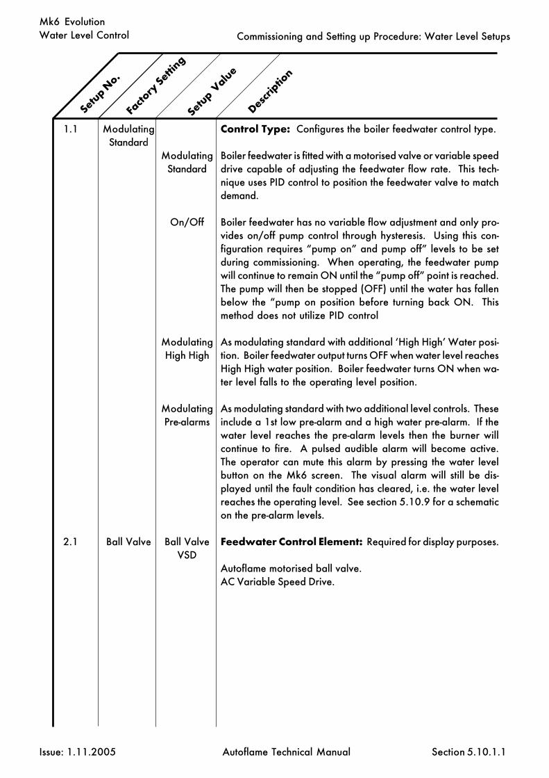
Water Level Control
Issue: 1.11.2005 Autoflame Technical Manual Section
Mk6 Evolution
1.1
2.1
ModulatingStandard
Ball Valve
ModulatingStandard
On/Off
ModulatingHigh High
ModulatingPre-alarms
Ball ValveVSD
Control Type: Configures the boiler feedwater control type.
Boiler feedwater is fitted with a motorised valve or variable speeddrive capable of adjusting the feedwater flow rate. This tech-nique uses PID control to position the feedwater valve to matchdemand.
Boiler feedwater has no variable flow adjustment and only pro-vides on/off pump control through hysteresis. Using this con-figuration requires “pump on” and pump off” levels to be setduring commissioning. When operating, the feedwater pumpwill continue to remain ON until the “pump off” point is reached.The pump will then be stopped (OFF) until the water has fallenbelow the “pump on position before turning back ON. Thismethod does not utilize PID control
As modulating standard with additional ‘High High’ Water posi-tion. Boiler feedwater output turns OFF when water level reachesHigh High water position. Boiler feedwater turns ON when wa-ter level falls to the operating level position.
As modulating standard with two additional level controls. Theseinclude a 1st low pre-alarm and a high water pre-alarm. If thewater level reaches the pre-alarm levels then the burner willcontinue to fire. A pulsed audible alarm will become active.The operator can mute this alarm by pressing the water levelbutton on the Mk6 screen. The visual alarm will still be dis-played until the fault condition has cleared, i.e. the water levelreaches the operating level. See section 5.10.9 for a schematicon the pre-alarm levels.
Feedwater Control Element: Required for display purposes.
Autoflame motorised ball valve.AC Variable Speed Drive.
5.10.1.1
Facto
ry Setti
ng
Setup V
alue
Descrip
tion
Setup N
o.
Commissioning and Setting up Procedure: Water Level Setups

Water Level Control
Issue: 1.11.2005 Autoflame Technical Manual Section
Mk6 Evolution
3.1
4.1
4.2
5.1
5.2
50%
20 seconds
10%
OFF
10%
5% –100%
0 - OFF1–100seconds
1% - 50%
OFF1-100
seconds
1%-50%
Proportional Band: When using PID, the controller output isproportional to the error between the current water level andthe required operating level. This setup represents a percentageof the total band between 1st low and the control point used toproportion the output. The following diagram illustrates this:
Integral Time: This setup is used to set a period of time n forintegral action. At these intervals a percentage (See IntegralFactor) of the present offset from the control point variable isadded or subtracted to the present proportional value.N.B. If configured as OFF no integral action is performed.Only applies when modulating control type is configured.
Integral Factor: This setup is used to set the percentage of thepresent offset from the control point variable to be added orsubtracted from the present proportional value.N.B. Only applies when modulating control type is configured.See Also: Integral Time, Proportional Band.
Derivative Time: With derivative action, the controller outputis proportional to the rate of change of the water level. Thissetup controls the time interval between the controller compar-ing the current water level and the required water level points.N.B. If configured as OFF no derivative action is performed.Only applies when modulating control type is configured.See Also: Derivative Deadband, Derivative Response Sensitivity.
Derivative Deadband: This setup is used to configure themargin above and below the required level within which there isno derivative action.N.B. Only applies when modulating control type is configured.See Also: Derivative Time, Derivative Response Sensitivity.
5.10.1.2
Commissioning and Setting up Procedure: Water Level Setups
Facto
ry Setti
ng
Setup V
alue
Descrip
tion
Setup N
o.
1st Low
Control Point
Proportional Band
Valve Fully Open
Valve Fully
Closed

Water Level Control
Issue: 1.11.2005 Autoflame Technical Manual Section
Mk6 Evolution
5.3
6.1
6.2
7.1
7.2
7.3
7.4
10%
152
2432
OFF
5
30
10
1%-100%
50-4050
50-4050
OFF1-120
1-100
10-100%
5-100
Derivative Response Sensitivity: This setup indicates thepercentage of feedwater increase or decrease that is inflictedby the derivative action.N.B. Only applies when modulating control type is configured.See Also: Derivative Time, Derivative Deadband.
Potentiometer Close Position: Servo potentiometer feed-back at close position.N.B. This is only required when configured for use with amotorized valve.See Also Potentiometer Open Position
Potentiometer Open Position: Servo potentiometer feed-back at open position.N.B. This is only required when configured for use with amotorized valve.See Also Potentiometer Close Position
Sudden Pressure Drop: If enabled setup 7 temporarily raisesthe water level control point in the event of a sudden boilerpressure drop. A change of pressure over time is tested for. Ifthe pressure change is greater than the amount specified thewater level control point is raised on a scaled basis accordingto the deviation of the boiler Required setpoint and Actualvalues. Once the boiler pressure is within a band of the re-quired value the raised control point effect is cleared. This bandis the same amount as set in 7.2. The function can be disabledaltogether see 7.1.
Sudden Pressure Drop- Time Between Readings:Period of seconds over which the change of pressure is tested.(OFF - sudden pressure drop function disabled)
Sudden Pressure Drop- Change in Pressure (and clearband): Amount of pressure drop over time (specified in 7.1)that must occur for raised control point to be triggered.
Sudden Pressure Drop- Percent Increase Scale:Water level control point percent increase scale.
Sudden Pressure Drop- Pressure Scale:Pressure scale - offset from Required value.
5.10.1.3
Commissioning and Setting up Procedure: Water Level Setups
Facto
ry Setti
ng
Setup V
alue
Descrip
tion
Setup N
o.

Water Level Control
Issue: 1.11.2005 Autoflame Technical Manual Section
Mk6 Evolution
8.1
9.1
10.1
10.2
11.1
12.1
20.1
20.2
21.1
RUNS
1.0%
1.0%
constant
30%
enabled
10.0
10.0
80F26C
RUNSSTOPS
0-2.00%
0-10.0%
constantpropor-tioned
0-100%
enableddisabled
0.1-999.9
0.1-999.9
32-212F0-100C
Burner Operation at High Water:Sets whether the boiler should continue to run or stop when ahigh water condition exists.
Boiler Standing Losses:Percentage of boiler Maximum Continous Rating.N.B. For the purpose of steam flow metering only.
Boiler Blow Down Losses:Percentage of boiler Maximum Continous Rating.N.B. For the purpose of steam flow metering only.
Boiler Blow Down Loss Calculation Method:
Fixed loss rate.Loss rate proportioned to firing rate.
Pump Turn Off Point: When the water level increases abovethe control point the pump can be set to turn off at the pointselected by this setup. The point is the percentage distancebetween the working control point and high water.N.B. Only applies when modulating control type is configured.
Auxiliary Alarm Inputs: If enabled the auxiliary mainsvoltage terminals for 2nd LOW, 1st LOW & HIGH WATER arebrought into effect. These operate in addition to the twocapacitance probes.
Deairator Make Up Water Flow Range: Only relevant ifDeairator feedwater method in use. Set value that representsflow at 20mA - Gallons per Minutes if Imperial Units, Litres perSecond if Metric. (4mA represents zero flow)
Deairator Return (Condensate) Water Flow Range: Onlyrelevant if Deairator feedwater method in use. Set value thatrepresents flow at 20mA - Gallons per Minutes if Imperial Units,Litres per Second if Metric. (4mA represents zero flow)
Default Feedwater Temperature: Feedwater temperaturevalue used if Feedwater Temperature sensor(s) not fitted.Displayed as F or C according to Units set (Option 65).
5.10.1.4
Commissioning and Setting up Procedure: Water Level Setups
Facto
ry Setti
ng
Setup V
alue
Descrip
tion
Setup N
o.

Water Level Control
Issue: 1.11.2005 Autoflame Technical Manual Section
Mk6 Evolution
22.1
22.2
22.3
23.1
24.1
25.1
25.2
0
0
0
disabled
Type 2
300
300
012
1-80
1-50
enableddisabled
Type 1Type 2
30-600
30-60
TB Output Terminal Function:TDS Top BlowdownON Above Switch Point (value set in 22.2)ON Below Switch Point (value set in 22.2)
Switch Point: (only relevant if 22.1 = 1 or 2)
Switch Point Hysteresis: (only relevant if 22.1 = 1 or 2)If 22.1 = 1 the TB output switches ON when the modulatingvalue angle becomes greater than the switch point (22.2). TheTB output switches OFF when the modulating value angle be-comes less than the switch point minus the hysteresis amount(i.e. 22.2 minus 22.3).If 22.1 = 2 the TB output switches ON when the modulatingvalue angle becomes less than the switch point (22.2). The TBoutput switches OFF when the modulating value angle becomesmore than the switch point plus the hysteresis amount (i.e. 22.2plus 22.3).In either case ensure the values entered are rational - IE in thecase of a valve the ON/OFF points are between 1 to 89 degrees.
TOP BLOW DOWN MANAGEMENT: If enabled the Top BlowDown Management screen will be displayed when appropriate- see TDS section of this manual. Setup 22.1 must be set to 0 sothe TB output terminal performs the Top Blow Down function.
WATER LEVEL PCB TYPE:
First issue Water Level PCB.Second Issue Water Level PCB - includes Top Blow Down &De-Aireator facilities
Test time to 1st low
Test time to 2nd Low
5.10.1.5
Commissioning and Setting up Procedure: Water Level Setups
Facto
ry Setti
ng
Setup V
alue
Descrip
tion
Setup N
o.

Water Level Control
Issue: 1.11.2005 Autoflame Technical Manual Section
Mk6 Evolution
5.10.1.6 Water Level Parameters
N.B. The software is fixed to operate on 2 probes
To enter the water level parameters:Set parameter 109 to 1 and press enter. Go into the water level commissioning mode and enterwater level setups. After setup 12.1, these extra setups will be entered.To reset all the water level set-ups and water level parameters to their default settings, set setup 6.1to 51 and 6.2 to 4049.
5.10.1.6.1
Commissioning and Setting up Procedure: Water Level Setups
A.1
B.1
C.1
D.1
D.2
E.1
E.2
E.3
E.4
F.1
10 (secs)
5 (secs)
2.0%
1 (secs)
1 (secs)
1500Hz
0
1.5
30 (secs)
0.9
1-20
1-100
0.1-20%0=off
1-20
1-20
0-2000
0-2000
1-10
1-200
0-5
Probe filtering time.Every second each probe takes 10 readings. This is then aver-aged over the value set in this parameter.
Control element update time.This is how often the modulating feed water valve will be movedin response to variations in the water level.
Control point deadline.No further modulation will occur wihin 2.0% of the control point0 = control point100 = 1st low
PK PK sampling period.Peak to peak sampling period (highest/lowest).
PK PK update time.
Min mismatch.1500Hz = 3” or 75mmProbe 1 is used as the reference based on the commissioningdata. This probe assesses the value of probe 2 to establish ifthere is a mismatch present (outside 1500Hz). Mismatch is aserious prolem ans is safety critical. If a probe mismatch occursthe probes may need cleaning.
Max mismatch.
Mismatch multiplier.
Mismatch time.If the mismatch exceeds 30 seconds then the system will shutdown. If the value of probe 2 moves back inside the 1500 win-dow then this timer is reset.N.B. First low takes priority over mismatch.
Tubrbulence factor.This value corresponds to the predicted water level.
Setup V
alue
Descrip
tion
Setup N
o.
Facto
ry Setti
ng

Water Level Control
Issue: 1.11.2005 Autoflame Technical Manual Section
Mk6 Evolution
G.1
G.2
G.3
H.1
J.1
J.2
K.1
K.2
L.1
0%
10 (secs)
10
1
1mm
10 (secs)
5 PSI
5 PSI
1500 Hz
0-100%
0-50
1-100
10
1-100
0
1-100
1-100
1-100
1-30000
Expansion offset.
Expansion turb time.
Expansion turb amount.
Control point method.Averages the data between both probes.Works off the readings from probe 1 only (control probe).The checks between the 2 probes are still carried out.
Detect turbulence level.If the water is still the frequency will drop below 10Hz and afault will occur. This is non-movement detection.Disabled
Detect turbulence time.N.B. If J.1 or J.2 is set to 0, then this function is disabled.
Steam flow start pressure offset.This is the required pressure. If there is pressure, no steam willbe produced if within 5 PSI of hte required value. The systemis deemed to be producing steam so steam flow metering willcommence.
Steam flow stop pressure offset.Steam is produced until the pressure drops below 5 PSI of therequired value.
Max probe drift.Disabled
5.10.1.6.2
Commissioning and Setting up Procedure: Water Level Setups
Facto
ry Setti
ng
Setup V
alue
Descrip
tion
Setup N
o.

Water Level C
ontrol
Issue: 1.11.2005A
utoflame Technical M
anualSection
Mk6 Evolution
Full set of commissioned data:
First line: Actual commissioned value (Hz)Second line: Nominal reference value (Hz)Third line: Difference between this commis-sioned value and one below
AND Temperature (C) of sensor on PCBat commissioning
There are 2 possibilities:
MM requesting data from thewater level board
END OF PROBE LEVEL
2ND LOW LEVEL
1ST LOW LEVEL
CONTROL POINT
HIGHWATER LEVEL
REPEAT OFHIGHWATER LEVELDATA
HIGHWATER LEVEL
PUMP ON
PUMP OFF
1ST LOW LEVEL
2ND LOW LEVEL
END OF PROBE LEVEL
PROBE 1 PROBE 2
1- Using the modu-lating water system
2- Using the pumpon/off system
Com
missioning and Setting up Procedure: D
iagnostics
Set of 7 analogue inputs
Signal from the modulatingfeed water valveValue between 152 (close)and 2432 (open)
Proportional value- probe 2
Checking for communication be-tween the MM and water level board
Check that probes 1/2 are present.If not a COMMS error would occur
Proportional value- probe 1
Average of P1 and P2
Derivative- avoid using
Checking for a valid set ofcommissioning data
Checking for valid setups
Integral built up so far
NOK= not OK
5.10.2.1

Water Level C
ontrol
Issue: 1.11.2005A
utoflame Technical M
anualSection
Mk6 EvolutionSignal from probe
Probe 1 Probe 2
Reference signal from reference capacitor
Filtered value of signal
Corrected filtered value
Working temperature
Control point value- at commissioningAverage of probe 1 and probe 2-based on several factors
Filtered reading of the 10 values
Corrected to reference- drift
Interim values based on 10 readings
10 readings for probes 1 and 2:Made over a 1 second period-
every 100 milliseconds
5.10.2.2
Com
missioning and Setting up Procedure: D
iagnostics

Water Level Control
Issue: 1.11.2005 Autoflame Technical Manual Section
Mk6 Evolution
READ ALL THOROUGHLY BEFORE COMMENCING WORK
1) Firstly, power to the system must be removed in order to make mechanicaladjustments.
2) In order to ensure that the valve is fully closed the following pictures must befollowed:
It is essential to check the feed water valve position and adjust this to the close position.This is done using the crank and checking the position of the valve stem out of the valve.
3) The coupling must then be attached to the feed water valve and correctly alligned asin the picture, and the servo motor/actuator must be at exactly 90 degrees to the feed watervalve (flow through the valve). When the servo motor is supplied, it comes in the 0 degreeposition.
5) The next procedure is to make electrical changes (please check that there is still nopower to the system)
Remove the lid and the end covering as shown in the diagrams below. In the end sectionthe wires labelled CW (clockwise wire) and CCW (counterclockwise wire) must be removedsince if present they will make the valve search for the operating position. All other wires mustbe kept in place including the ones on top.
DANGER:120 volt live connections
Wires to beremoved Carefully rotate the potentiometer to
change the diagnostic readings onthe MM display
Tamper proof screws tobe loosened in order tomove the potentiometer
5.10.3 Replacing the servo motor/actuator for a feed water valve
4) After these mechanical changes, the allignment may be correct. Check the displaydiagnostics as covered in parts 6 and 7.
5.10.3.1
Commissioning and Setting up Procedure: Feed Water Valve

Water Level Control
Issue: 1.11.2005 Autoflame Technical Manual Section
Mk6 Evolution
6) Be careful: in the next procedure there are live connections showing. Turn the poweron to the system and enter the commissioning mode on the MM screen. In parameters, changeparameter 83 to 1 (on) to display the diagnostics. Then enter this and re-enter commissioningmode and go into water level commisssioning. The screen below is one of the diagnostic dis-plays available.
7) It is now necessary to carefully rotate the potentiometer position, checking the MMscreen and watching the value indicated below. The close position value is 152, so a value of152-170 will correspond to the close position.
Once this has been adjusted, tighten the tamper proof screws on the potentiometer,remove power from the system, reconnect the CW and CCW wires and replace the end and topcoverings.
The feed water valve should now be ready for operation.
Diagnostic value that needs to beadjusted to 152-170As the potentiometer is rotated thisvalue will change
5.10.3.2
Commissioning and Setting up Procedure: Feed Water Valve
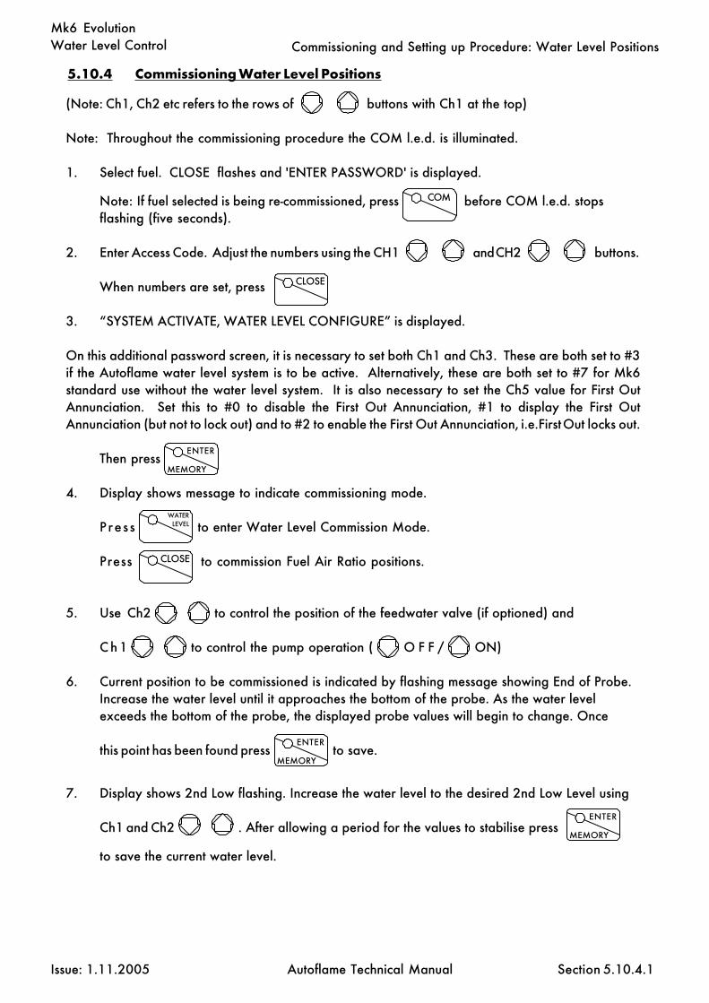
Water Level Control
Issue: 1.11.2005 Autoflame Technical Manual Section
Mk6 Evolution
(Note: Ch1, Ch2 etc refers to the rows of buttons with Ch1 at the top)
Note: Throughout the commissioning procedure the COM l.e.d. is illuminated.
1. Select fuel. CLOSE flashes and 'ENTER PASSWORD' is displayed.
Note: If fuel selected is being re-commissioned, press before COM l.e.d. stopsflashing (five seconds).
2. Enter Access Code. Adjust the numbers using the CH1 and CH2 buttons.
When numbers are set, press
3. “SYSTEM ACTIVATE, WATER LEVEL CONFIGURE” is displayed.
On this additional password screen, it is necessary to set both Ch1 and Ch3. These are both set to #3if the Autoflame water level system is to be active. Alternatively, these are both set to #7 for Mk6standard use without the water level system. It is also necessary to set the Ch5 value for First OutAnnunciation. Set this to #0 to disable the First Out Annunciation, #1 to display the First OutAnnunciation (but not to lock out) and to #2 to enable the First Out Annunciation, i.e. First Out locks out.
Then press
4. Display shows message to indicate commissioning mode.
Pres s to enter Water Level Commission Mode.
Press to commission Fuel Air Ratio positions.
5. Use Ch2 to control the position of the feedwater valve (if optioned) and
C h 1 to control the pump operation ( O F F / ON)
6. Current position to be commissioned is indicated by flashing message showing End of Probe.Increase the water level until it approaches the bottom of the probe. As the water levelexceeds the bottom of the probe, the displayed probe values will begin to change. Once
this point has been found press to save.
7. Display shows 2nd Low flashing. Increase the water level to the desired 2nd Low Level using
Ch1 and Ch2 . After allowing a period for the values to stabilise press
to save the current water level.
COM
CLOSE
ENTER
MEMORY
WATERLEVEL
ENTER
MEMORY
CLOSE
5.10.4.1
5.10.4 Commissioning Water Level Positions
Commissioning and Setting up Procedure: Water Level Positions
ENTER
MEMORY

Water Level Control
Issue: 1.11.2005 Autoflame Technical Manual Section
Mk6 Evolution
RUN
8. If the unit is configured for On/Off operation repeat step 6 for: 1st Low, Pump On, Pump Off,and High Water Positions otherwise if the unit if configured for modulating control repeat step6 for: 1st Low, Control Point and High Water (and High High water if applicable) Levels. Ateach level the display will flash the position currently being commissioned. When the lastpoint has been entered the Water Level Commission data will be permanantely saved. Proceed to step 8. Note that after each point is entered it is necessary to press the Water Levelbutton to confirm the commissioning of the next point, thereafter the ENTER led will startflashing again.
9. After entering the final position (High Water) the RUN L.E.D. will begin to flash. Beforeproceding further reduce the water level to the control point level (or pump on). This willprevent the unit from registering a high water alarm immediately after the system has reset.
10. Press to exit commissioning mode and return to normal (FAR) Fuel Air Ratio
Commissioning. If FAR is not required deselect and then reselect fuel to return to RUN mode.
Commissioning and Setting up Procedure: Water Level Positions
5.10.4.2

Water Level Control
Issue: 1.11.2005 Autoflame Technical Manual Section
Mk6 EvolutionCommissioning and Setting up Procedure: Water Level Positions
5.10.4.1
END OF PROBE
2ND LOW
1ST LOW
CONTROL POINT
HIGH WATER
1 2
40242 40278
END OF PROBE
2ND LOW
1ST LOW
PUMP ON
HIGH WATER
1 2
40242 40278
PUMP OFF
5.10.4.1 Commissioning Screens
Commissioning screen displayed forstandard modulating water control.
Commissioning screen displayed foron/off water control
END OF PROBE
2ND LOW
1ST LOW
HIGH WATER
1 2
40242 40278
Commissioning screen displayed formodulating water control
with High High water
CONTROL POINT
HIGH HIGH WATER

Water Level Control
Issue: 1.11.2005 Autoflame Technical Manual Section
Mk6 Evolution
5.10.4.2
Commissioning and Setting up Procedure: Connection Diagram (EVO 1 system)
5.10.4.2 Expansion PCB Connection Terminals
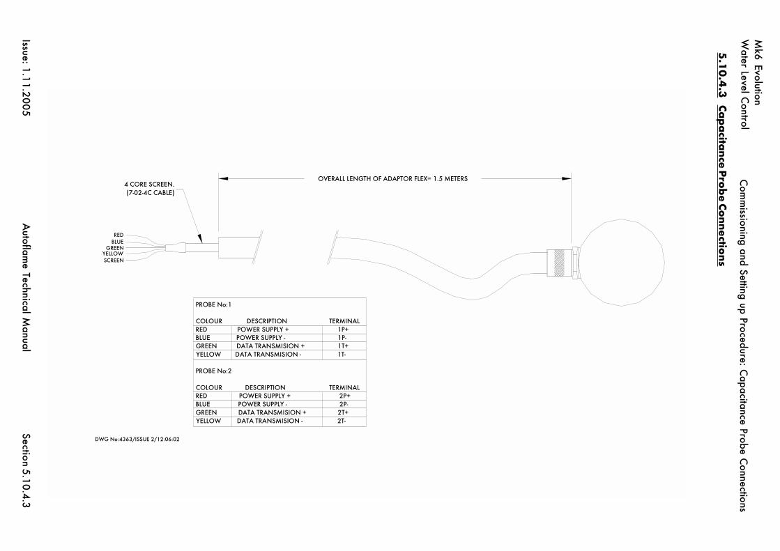
Water Level C
ontrol
Issue: 1.11.2005A
utoflame Technical M
anualSection
Mk6 Evolution
5.10.4.3
Com
missioning and Setting up Procedure: C
apacitance Probe Connections
PROBE No:1
COLOUR DESCRIPTION TERMINALRED POWER SUPPLY + 1P+BLUE POWER SUPPLY - 1P-GREEN DATA TRANSMISION + 1T+YELLOW DATA TRANSMISION - 1T-
PROBE No:2
COLOUR DESCRIPTION TERMINALRED POWER SUPPLY + 2P+BLUE POWER SUPPLY - 2P-GREEN DATA TRANSMISION + 2T+YELLOW DATA TRANSMISION - 2T-
4 CORE SCREEN.(7-02-4C CABLE)
OVERALL LENGTH OF ADAPTOR FLEX= 1.5 METERS
REDBLUE
GREENYELLOWSCREEN
DWG No:4363/ISSUE 2/12:06:02
5.1
0.4
.3Ca
pa
citance P
rob
e Connectio
ns

Water Level Control
Issue: 1.11.2005 Autoflame Technical Manual Section
Mk6 Evolution
5.10.5 Operational Checks
All local & national codes for safe operation of boiler plant must be respected. If inany doubt contact your local specialist authority.
Water level operation must be checked after commissioning or subsequent to modification of anysetups.
Set the system to RUN mode and allow the burner to fire. With the boiler supplying steam at asteady rate check that the water level is maintained at the control point. Note: This is for modulatingcontrol. If the system is configured for on/off control check that the boiler feedwater pump turns onand off appropriately at the commissioined points. Ensure that all audible and visual alarm indica-tors are inactive.
Reduce the level of the water (by blow down or other suitable means). Check that a 1st low alarmoccurs when the water level is just below the commissioned 1st low level. Note: The burner willstop in this condition.
Ensure that the 1st low audible and visual indicators are active.If fitted, press the external mute/reset button and check that the audible alarm is muted.
Reduce the level of the water further and check that the 2nd low alarm is displayed when the waterlevel is just below the commissioned 2nd low level. Note: The burner will remain stopped in thiscondition.
Ensure that the 2nd low audible and visual indicators are active.If fitted, press the external mute/reset button and check that the audible alarm is muted.
All 1st Low/2nd low alarm conditions must be cleared before proceeding to test the high water.To test high water it will be necessary to increase the water level to just above that of the commis-sioned high water position. If there is no means to manually increase the level of the water it ispossible to select Water Level Commission mode and increase the level of the water manually. Thiscan be performed by using the Ch1 and Ch2 controls. The unit can then be restarted by de-selectingand re-selecting the fuel. The unit will restart in RUN mode and should report a high water alarm.Check the burner operation runs or stops according to the set up (8.1).
Ensure that the high water audible and visual indicators are active.If fitted, press the external mute/reset button to check that the audible alarm is muted.
Check the operation of the TB output terminal.
5.10.5
Commissioning and Setting up Procedure: Operational Checks

Water Level Control
Issue: 1.11.2005 Autoflame Technical Manual Section
Mk6 Evolution
5.10.6 Terminal Description - TDS version system
P- Feedwater control valve potentiometer excitation voltage -ve.PW Feedwater control valve potentiometer wiperP+ Output. Feedwater control valve potentiometer excitation voltage +ve.
Max load 5mA.
T1 Feed water temperature sensor.T2 Steam temperature sensor.T1A Condensate water temperature sensor.V UnusedMF 4-20mA input - Make up Water FlowCF 4-20mA input - Condensate Water Flow+I +V Outputs. Analog signals to control VSD. Max output under normal
operation 10V/20mA. (Current Input impedance max 250R)
3T- 3T+ 3P- 3P+ Connections solely dedicated to Autoflame TDS Probe1T- 1T+ 1P- 1P+ Connections solely dedicated to Autoflame capacitance Probe 12T- 2T+ 2P- 2P+ Connections solely dedicated to Autoflame capacitance Probe 2
FO1 - FO15 First Out annunciation inputs (mains voltage input)HAI High water Auxiliary Input (mains voltage input)1AI 1st low water Auxiliary Input (mains voltage input)2AI 2nd low water Auxiliary Input (mains voltage input)M/R Water Level Alarm mute/reset (mains voltage input)TST Test Facility Activate (mains voltage input)
PF Mains supply live/hot to alarm devices/motorized valve etc.
TB Top Blow Down (ouput switched neutral)1LV 1st Low visual alarm (output switched neutral).H1A High and 1st low water audible alarm (output switched neutral).2LV 2nd Low visual alarm (output switched neutral).2LA 2nd Low audible alarm (output switched neutral).HWV High water visual alarm (output switched neutral).BB Bottom Blow Down (ouput switched neutral)BFW Feedwater pump on/off. (output switched neutral)MVI Feedwater control valve motor drive – increase. (output switched neutral)MVD Feedwater control valve motor drive – decrease. (output switched neutral)NC No Connection
Note that all the “-” & P- terminals on the top left connection strip are common to each other, All of thecircuitry assosciated with this terminal strip (analog inputs and outputs) is isolated from earth poten-tial (i.e. floating). If a VSD is not used, or a VSD is used that has isolated input signal circuitry, link oneof the “-” terminals to an S terminal (EG between P- and the adjacent S terminal to its left). If using aVSD and the VSD signal input circuitry is earthed do NOT install a link.
ALL TERMINALS MARKED S ARE CONNECTED TO MAINS EARTH TERMINAL 66 ON THEMK6EVO AND ARE ONLY FOR CONNECTION TO CABLE SCREENS.
5.10.6
Commissioning and Setting up Procedure: Terminal Description

Water Level Control
Issue: 1.11.2005 Autoflame Technical Manual Section
Mk6 Evolution
5.10.7 Water Level Electrical Specification
Classifications
Outputs: 120/230 V
MVD 1.5AMVI 1.5A
BFW 250mA Must be connected through contactorBB 250mA Must be connected through contactor
HWV 100mA (alarm indicator)
2LA 100mA (alarm indicator)2LV 100mA (alarm indicator)
H1A 100mA (alarm indicator)1LV 100mA (alarm indicator)
TB 250mA Must be connected through contactor
PF Maximum 2A (load currents for above terminals)
Note MVD MVI only one output switched at a time.Max number of alarm indicators on at any time is 3 (1LV, 2LA, 2LV)Use 4-core screened cable to connect capacitance probes. Refer to section 2.9.11.2
Main Voltage Signal Inputs
At 120V Current Loading Aprroximately 0.6mAAt 230V Current Loading Approximately 1.15mA
Refer to MK6 Electrical Specifications Section (2.14.2.9) for other general ratings.
5.10.7
Commissioning and Setting up Procedure: Electrical Specification

Water Level Control
Issue: 1.11.2005 Autoflame Technical Manual Section
Mk6 Evolution
MK
6 E
VO
LUTI
ON
WIT
H W
ATE
R L
EVEL
P.C
.B. F
ITTE
D
Commissioning and Setting Up Procedure: Fuse Position/Rating
2A(T) Fuse
5.10.8
5.10.8 Fuse Position/Rating

Water Level Control
Issue: 1.11.2005 Autoflame Technical Manual Section
Mk6 EvolutionCommissioning and Setting Up Procedure: Fuse Position/Rating
5.10.9
5.10.9 Display on the DTI (Data Transfer Interface)
HIGH WATERALARM
PRE HIGH WATERALARM
CONTROL POINT
PRE 1st LOWALARM
1st LOWBURNER OFF
2nd LOWLOCKOUT
VIRTUALGAUGE GLASS
0mm
110mm
180mm
260mm
352mm
450mm
ACTUAL LEVEL = 140mm
END OF PROBE
TOP OF PROBE
50mm
NOTES:
BURNER CAN BE OPTIONED OFF OR REMAINON AT THIS POINT. (SEE SETUP #8.1)
SETU
P #
11.1
PUMP TURN OFF POINT. THE PUMP WILLTURN OFF AT A % DISTANCE BETWEEN THE CONTROL POINT AND THE HIGH WATER
DEFAULT PUMP OFF POINT. 30%
AUDIBLE ALARM & VISUAL ALARM CONSTANTOUTPUT. ALARM CAN BE MUTED.
AUDIBLE ALARM & VISUAL ALARM PULSEDOUTPUT. ALARM CAN BE MUTED.
AUDIBLE ALARM & VISUAL ALARM PULSEDOUTPUT. ALARM CAN BE MUTED.
MODULATING VALVE WILL BE CLOSEDABOVE CONTROL POINT.
AUDIBLE ALARM & VISUAL ALARM CONSTANTOUTPUT. ALARM CAN BE MUTED.
AUDIBLE ALARM & VISUAL ALARM CONSTANTOUTPUT. ALARM CAN BE MUTED.
INFORMATION AS DISPLAYED THROUGH THE WINPCDTI SOFTWARE.
THIS POINT SHOULD BE THE BOTTOM OF THE ACTUAL SIGHT GLASS ON THE BOILER
GOOD PRACTICE STATES THIS DISTANCESHOULD BE A MINIMUM OF 50mm (2")
BURNER OFF. AUTOMATICALLY RESTARTS ONCE WATER LEVEL GOES ABOVE THE 1st LOW POINT

Water Level Control
Issue: 1.11.2005 Autoflame Technical Manual Section
Mk6 Evolution
5.11
Normal Operation: End User Day to Day Operation
5.11 Normal Operation
5.11.1 End User Day to Day Operation
The WLC product is designed to report and control levels of water within industrial steam boilers.The key features of the system are as follows:
• Reporting Level Alarms• Feedwater Control• Steam Flow Metering
Alarm level reporting deals with the ability to determine whether the current water level is above orbelow a predetermined level. These levels vary with each installation and must therefore be pro-grammed on site by a qualified commissioning engineer. For each installation there are a minimumof five level indication points representing the following levels:
• High High Water:• High Water:• High Water Pre-alarm:• Control Point:• 1st Low Pre-alarm:• 1st Low:• 2nd Low:• Bottom of probe:
(Note: the above arrangement is for water level modulation control. In the event of on/off levelcontrol there are six level indication points (pump on & pump off replace control point. These are theonly two types of level control).
5.11.2 Water Level Operation
It is ideal to maintain an amount of water in the boiler appropriate to the amount of steam beinggenerated. Should the water level drop below this ideal level by an excessive amount, it is necessaryto stop the burner firing. If there is insufficient water in the boiler damage may occur to its structure.In extreme cases there is the potential for the boiler to explode. The WLC herein is designed tomaintain a satisfactory level of water in the boiler, whilst controlling and reporting low water levelconditions. Its operation is as follows:
The water levels detailed above are described below:
High Water:A high water level, although not dangerous is undesirable as water may infiltrate the steam header. Ifthe boiler water level goes above this point the burner may or may not continue to run dependingon the system configuration. If a high water level condition is detected high water audible and visualindicators are activated to notify the user. The audible indicator may be muted by means of themute/reset push button.
Control Point:Ideal water level regulation point. There are no audible or visual indicators active.

Water Level Control
Issue: 1.11.2005 Autoflame Technical Manual Section
Mk6 Evolution
5.11.2.1
1st Low:A 1st low water level is a point below the control point at which the burner will turn off. If the waterlevel falls below this point 1st low audible and visual indicators are activated. The audible indicatormay be muted by means of the mute/reset push button. If the water level is restored above this pointthe burner will start automatically and all indicators will be reset.
2nd Low:A 2nd low water level is a point below 1st Low at which the burner will remain off. If the water levelfalls below this point 2nd low audible and visual indicators are activated. The audible indicator maybe muted by means of the mute/reset push button. Even if the water level is restored above this pointthe burner will remain off. Operator intervention is required to manually reset the system and canonly be performed once the level is above the 2nd Low point - the water level L.E.D will flash whenthis condition is satisfied. The 2nd low reset condition is non-volatile - if the system is powered downthe reset condition will be restored when power is reapplied. In this scenario the operator reset willstill be necessary.
Bottom of probe:The bottom of probe level is used to identify the point below which the probe cannot obtain a validwater level. It has no operational use.
Normal Operation: End User Day to Day Operation

Water Level Control
Issue: 1.11.2005 Autoflame Technical Manual Section
Mk6 Evolution
1ST LOW
2ND LOW
CONTROL POINT
HIGH WATER
1ST LOW
2ND LOW
HIGH WATER
PUMP OFF
PUMP ON
Boiler water level screen displayed formodulating standard water control.
Boiler water level screen displayed foron/off water control.
Virtual guage glass screendisplayed for modulating standard
water control.
Virtual guage glass screendisplayed for on/off
water control.
Several different displays are available to provide the operator with information when using theWater Level Control.
WATERLEVELPRESS
WATERLEVELPRESS
5.11.2.2
Normal Operation: End User Day to Day Operation

Water Level Control
Issue: 1.11.2005 Autoflame Technical Manual Section
Mk6 Evolution
5.11.2.3
Boiler water level screen displayed formodulating high high water control.
Virtual guage glass screendisplayed for modulating high high
water control.
Several different displays are available to provide the operator with information when using theWater Level Control.
WATERLEVELPRESS
1st Low
2nd Low
Hi Hi Level
High Level
Op. Level
Normal Operation: End User Day to Day Operation

Water Level Control
Issue: 1.11.2005 Autoflame Technical Manual Section
Mk6 Evolution
From Virtual Gauge Glass Screen
5.11.2.4
Feedwater Valve ScreenAutoflame Ball Valve
Steam Flow ScreenMetric Units
WATERLEVELPRESS
STEAM FLOW SCREEN
UNITS DISPLAYED
IMPERIAL METRIC
Steam Flow lb/hr Kg/hrHeat/Steam Btu/lb KJ/KgFeedwater Temp. F CSteam Temp. F CSteam Pressure PSI BarTotalised Steam lbs Kgs
Normal Operation: End User Day to Day Operation

Water Level Control
Issue: 1.11.2005 Autoflame Technical Manual Section
Mk6 Evolution
5.11.2.5
Water Level Alarm Record Screen
WATERLEVELPRESS
WATERLEVELPRESS
From Steam Flow Screen
To Boiler Water Level Screen
Normal Operation: End User Day to Day Operation
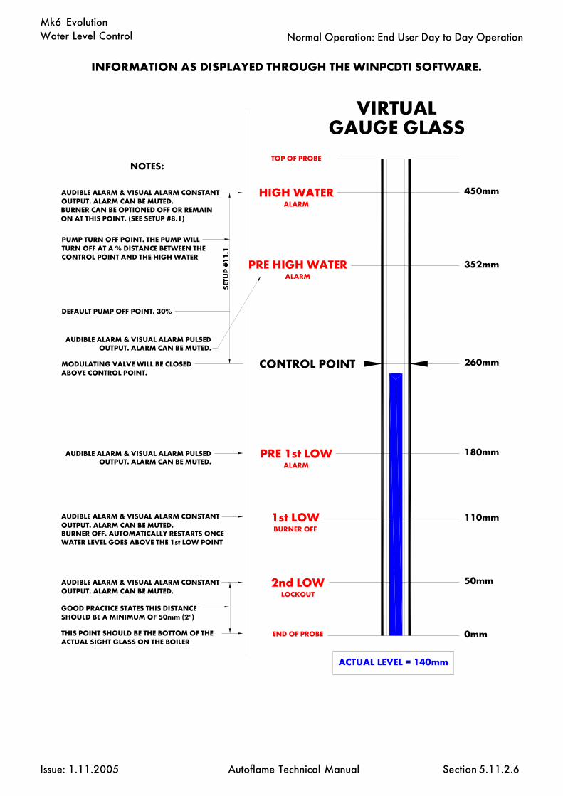
Water Level Control
Issue: 1.11.2005 Autoflame Technical Manual Section
Mk6 Evolution
5.11.2.6
Normal Operation: End User Day to Day Operation
HIGH WATERALARM
PRE HIGH WATERALARM
CONTROL POINT
PRE 1st LOWALARM
1st LOWBURNER OFF
2nd LOWLOCKOUT
VIRTUALGAUGE GLASS
0mm
110mm
180mm
260mm
352mm
450mm
ACTUAL LEVEL = 140mm
END OF PROBE
TOP OF PROBE
50mm
NOTES:
BURNER CAN BE OPTIONED OFF OR REMAINON AT THIS POINT. (SEE SETUP #8.1)
SETU
P #
11.
1
PUMP TURN OFF POINT. THE PUMP WILLTURN OFF AT A % DISTANCE BETWEEN THE CONTROL POINT AND THE HIGH WATER
DEFAULT PUMP OFF POINT. 30%
AUDIBLE ALARM & VISUAL ALARM CONSTANTOUTPUT. ALARM CAN BE MUTED.
AUDIBLE ALARM & VISUAL ALARM PULSEDOUTPUT. ALARM CAN BE MUTED.
AUDIBLE ALARM & VISUAL ALARM PULSEDOUTPUT. ALARM CAN BE MUTED.
MODULATING VALVE WILL BE CLOSEDABOVE CONTROL POINT.
AUDIBLE ALARM & VISUAL ALARM CONSTANTOUTPUT. ALARM CAN BE MUTED.
AUDIBLE ALARM & VISUAL ALARM CONSTANTOUTPUT. ALARM CAN BE MUTED.
INFORMATION AS DISPLAYED THROUGH THE WINPCDTI SOFTWARE.
THIS POINT SHOULD BE THE BOTTOM OF THE ACTUAL SIGHT GLASS ON THE BOILER
GOOD PRACTICE STATES THIS DISTANCESHOULD BE A MINIMUM OF 50mm (2")
BURNER OFF. AUTOMATICALLY RESTARTS ONCE WATER LEVEL GOES ABOVE THE 1st LOW POINT

Water Level Control
Issue: 1.11.2005 Autoflame Technical Manual Section
Mk6 Evolution
5.11.3 First Out Status
If a water level control board is fitted, fifteen mains voltage inputs are available for first out statusindication.
To select the first out status screen press until the screen is displayed. It is displayed
between the VPS and lockout record screens.
The first out status indications are for monitoring only, they perform no burner control functions.
The descriptive labels for each input can be individually programmed by means of the infra-redupload software facility.
For each input a status of FAIL indicates a mains voltage on the input to that particular terminal. Avalue of NORMAL indicates no mains voltage to the input.
First Out Status Screen
FLAMESCANNERPRESS
To Lockout Record Screen
From VPS Status Screen
FLAMESCANNERPRESS
FLAMESCANNER
5.11.3.1
Normal Operation: End User Day to Day Operation

Water Level Control
Issue: 1.11.2005 Autoflame Technical Manual Section
Mk6 Evolution
Fuel Totalised ScreenMetric Units
5.11.3.2
FUELMETERINGPRESS
FUELMETERINGPRESS
Fuel Flow Metering ScreenMetric Units
Fuel Flow Metering
FUEL FLOW METERING SCREEN
As well as fuel flow metering information, thisscreen also shows a graphical profile of theFUEL/AIR ration profile derived from the CH1 andCH2 angular positions.
UNITS DISPLAYED
IMPERIAL METRIC
Instaneous Flow Mbtu/hr MWTotalised Flow Mbtus GJ
FUEL TOTALISED SCREEN
UNITS DISPLAYED
IMPERIAL METRIC
Fuel 1CUFt m3
Fuel 2lbs KgmsUS glns LtrsUS tons Tonnes
Fuel 3lbs KgmsUS glns LtrsUS tons Tonnes
Fuel 4CuFt m3
Normal Operation: End User Day to Day Operation
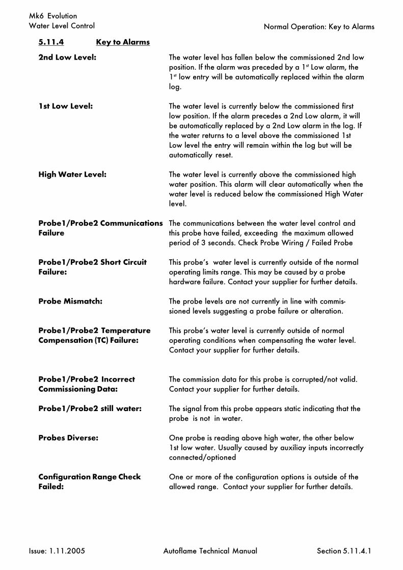
Water Level Control
Issue: 1.11.2005 Autoflame Technical Manual Section
Mk6 EvolutionNormal Operation: Key to Alarms
5.11.4.1
5.11.4 Key to Alarms
The water level has fallen below the commissioned 2nd lowposition. If the alarm was preceded by a 1st Low alarm, the1st low entry will be automatically replaced within the alarmlog.
The water level is currently below the commissioned firstlow position. If the alarm precedes a 2nd Low alarm, it willbe automatically replaced by a 2nd Low alarm in the log. Ifthe water returns to a level above the commissioned 1stLow level the entry will remain within the log but will beautomatically reset.
The water level is currently above the commissioned highwater position. This alarm will clear automatically when thewater level is reduced below the commissioned High Waterlevel.
The communications between the water level control andthis probe have failed, exceeding the maximum allowedperiod of 3 seconds. Check Probe Wiring / Failed Probe
This probe’s water level is currently outside of the normaloperating limits range. This may be caused by a probehardware failure. Contact your supplier for further details.
The probe levels are not currently in line with commis-sioned levels suggesting a probe failure or alteration.
This probe’s water level is currently outside of normaloperating conditions when compensating the water level.Contact your supplier for further details.
The commission data for this probe is corrupted/not valid.Contact your supplier for further details.
The signal from this probe appears static indicating that theprobe is not in water.
One probe is reading above high water, the other below1st low water. Usually caused by auxiliay inputs incorrectlyconnected/optioned
One or more of the configuration options is outside of theallowed range. Contact your supplier for further details.
2nd Low Level:
1st Low Level:
High Water Level:
Probe1/Probe2 CommunicationsFailure
Probe1/Probe2 Short CircuitFailure:
Probe Mismatch:
Probe1/Probe2 TemperatureCompensation (TC) Failure:
Probe1/Probe2 IncorrectCommissioning Data:
Probe1/Probe2 still water:
Probes Diverse:
Configuration Range CheckFailed:

Water Level Control
Issue: 1.11.2005 Autoflame Technical Manual Section
Mk6 EvolutionNormal Operation: Key to Alarms
5.11.4.2
Permanent Reset Input:
Keystuck Reset:
Permanent Test Input:
Incompatible Configuration:
Power Up EEPROM Failure:
Power Up- Incorrect state savedin EEPROM
The water level control or MM mute/reset button waspressed for longer than 10 seconds. To reset this alarmensure that both buttons are not pressed for at least 10seconds. This will then become a keystuck-reset alarm.
This alarm will occur after a permanent reset input fault.
The water level contrrol test input button was pressed forlonger than 60 seconds.
The configuration and commission data do not have match-ing control type options. This would occur if the configura-tion has been changed after commissioning.
The water level control has not been used before or has afaulty EEPROM. If the problem persists contact you sup-plier for further information.
The water level control has a corrupted EEPROM. If theproblem persists contact your supplier for further informa-tion.
5.11.4 Key to Alarms

Water Level Control
Issue: 1.11.2005 Autoflame Technical Manual Section
Mk6 Evolution
5.12 T.D.S. (Total Dissolved Solids) Management
5.12.1 The Philosophy of the T.D.S control system
To manage a steam boiler for optimum efficiency and reliability an important requirement is toensure that the Total Dissolved Solids (T.D.S) in the water are measured and controlled to notexceed a nominated level. It is generally accepted that for water tube boilers the level of T.D.Smeasured should not exceed 1,500 PPM by volume and for smoke tube boilers the T.D.S should notbe higher than 2,500 PPM by volume. The figures stated are not definitive and in all applicationsthe recommendations of the boiler manufacturer or water treatment chemist should be implemented.
1) It has been established that the conductivity of water is proportional to the measured T.D.S aslong as the temperature remains constant. Any variations in temperature will affect the measuredconductivity by nominally 2% per 1degree C. It follows that the temperature of the water must bemeasured and the conductivity reading must be adjusted before a T.D.S reading can be extrapolatedfrom this line of data.
The Autoflame system incorporates a temperature measurement sensor in the steam drum to estab-lish the steam temperature. This data stream is used to constantly correct the conductivity value.
2) A second variable that effects the conductivity measurement is polarization of the water sample.This occurs when electrical energy from the probe builds up a relatively tiny offset above or belowthe earth (0 volt value). This polarization value is typically noticeable when a continuous frequencyis being emitted from the probe as part of the conductivity measurement method.
The Autoflame system deals with the potential problem of polarization in the following manner. Theprobe measures any build up of voltage potential above or below earth or 0V in the water sample.The measured polarization voltage data is used to modify the conductivity calculation. TheAutoflame system emits electrical energy at a rate of 10x 300 microsecond pulses every second.This translates into a method where we are emitting electrical energy for 0.6% of the sample time.All other manufacturers who use the frequency method are emitting electrical energy for 100% ofthe sample time. It follows that the polarization problem in these cases would be 167 timesgreater!.
3) A third problem that effects the accuracy of the T.D.S measurement is the build up of scale on theprobe electrode. By design the water sampling container has been arranged so that the turbulencecreated during the blow down sequence will ensure that the probe remains effectively free of scaleor deposited solids that could be held in suspension.
4) The sampling container has a known orifice size. From this it is possible to calculate the percent-age losses due to surface blowdown. This is possible because the following parameters are known:Hole size, temperature, pressure, pressure drop across the solenoid and the time that the solenoid isopen for.
It can be seen from the above that the Autoflame T.D.S system deals succinctly with three of themain problem areas that are encountered when designing an accurate T.D.S control solution.
5.12
T.D.S. Introduction

Water Level Control
Issue: 1.11.2005 Autoflame Technical Manual Section
Mk6 Evolution
5.12.2 T.D.S Calibration (User Calibration Method)
The calibration of the Autoflame T.D.S control system should be carried out as detailed below.
1) When the boiler is at operating pressure/temperature and in a steady state condition the calibra-tion should be initiated by pressing the “COM” button with respect to the T.D.S. This will implementa top blow down and sample sequence (see pages 5.12.6.1 and 5.12.6.2). At this time a conductivityvalue at a specific temperature and pressure will be measured and stored in the systems memory(see point A on diagram, page 5.12.7).
2) A sample of boiler water can be taken via the probe container and cooled nominally to 25degrees C / 77 degrees F. Autoflame can supply a cooler that is close coupled to the T.D.S probemounting pot (see schematic pages 5.12.5.1 and 5.12.5.2).
3) The cooled sample must be analyzed for T.D.S content (PPM by volume). A hand held portableinstrument typically as manufactured by “Hanna Instruments” can be used for this purpose (typeHI98312). It is a vital part of this process that the hand held instrument is correctly calibrated in themanufactures recommended calibration solution. A water treatment chemist can carry out this task ifrequired.
4) When a T.D.S level is displayed on the chosen portable instrument, this value can then be en-tered into the Autoflame T.D.S control system (see point D on diagram page 5.12.7). This action willestablish the relationship between T.D.S PPM by vol with the conductivity value that is already heldin memory (point A on diagram page 5.12.7).
5) When the above sequence of events have been implemented the “RUN” button with respect toT.D.S can be pressed and the system will be calibrated and ready to setup the designed operationalprofile (see page 5.12.4).
5.12.2
T.D.S. User Calibration

Water Level Control
Issue: 1.11.2005 Autoflame Technical Manual Section
Mk6 Evolution
5.12.3 T.D.S Calibration (Automatic Internal Calibration Method)
The calibration of the Autoflame T.D.S control system should be carried out as detailed below.
1) When the boiler is at operating pressure/temperature and in a steady state condition the calibra-tion should be initiated by pressing the “COM” button with respect to the T.D.S. This will implementa top blow down and sample sequence (see pages 5.12.6.1 and 5.12.6.2). At this time a conductiv-ity value at a specific temperature and pressure will be measured and stored in the systems memory(see point A on diagram, page 5.12.7).
2) When the above sequence of events have been implemented wait one minute then the “RUN”button with respect to T.D.S can be pressed and the data at point ‘B’ (se page 5.12.7) will be calcu-lated and entered into the system memory. The system is now calibrated and the setup of the de-signed operational profile of the system can now be made (see page 5.12.4).
5.12.3
T.D.S. Automatic Internal Caliration
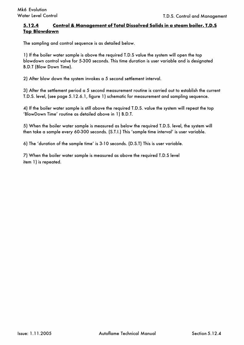
Water Level Control
Issue: 1.11.2005 Autoflame Technical Manual Section
Mk6 Evolution
5.12.4 Control & Management of Total Dissolved Solids in a steam boiler. T.D.STop Blowdown
The sampling and control sequence is as detailed below.
1) If the boiler water sample is above the required T.D.S value the system will open the topblowdown control valve for 5-300 seconds. This time duration is user variable and is designatedB.D.T (Blow Down Time).
2) After blow down the system invokes a 5 second settlement interval.
3) After the settlement period a 5 second measurement routine is carried out to establish the currentT.D.S. level, (see page 5.12.6.1, figure 1) schematic for measurement and sampling sequence.
4) If the boiler water sample is still above the required T.D.S. value the system will repeat the top‘BlowDown Time’ routine as detailed above in 1) B.D.T.
5) When the boiler water sample is measured as below the required T.D.S. level, the system willthen take a sample every 60-300 seconds. (S.T.I.) This ‘sample time interval’ is user variable.
6) The ‘duration of the sample time’ is 3-10 seconds. (D.S.T) This is user variable.
7) When the boiler water sample is measured as above the required T.D.S levelitem 1) is repeated.
5.12.4
T.D.S. Control and Management

Water Level Control
Issue: 1.11.2005 Autoflame Technical Manual Section
Mk6 Evolution
Option 1: Vertically mounted
5.12.5.1 Installation of the T.D.S. probe assembly
Illustrated below are two installation methods for the T.D.S probe incorporating Autoflame’s sam-pling system.
All dotted componients supplied by the customer.
5.12.5.1
T.D.S. Installation and Probe Assembly

Water Level Control
Issue: 1.11.2005 Autoflame Technical Manual Section
Mk6 Evolution
Option 2: Horizantally mounted
All dotted componients supplied by the customer.
5.12.5.2
T.D.S. Installation and Probe Assembly
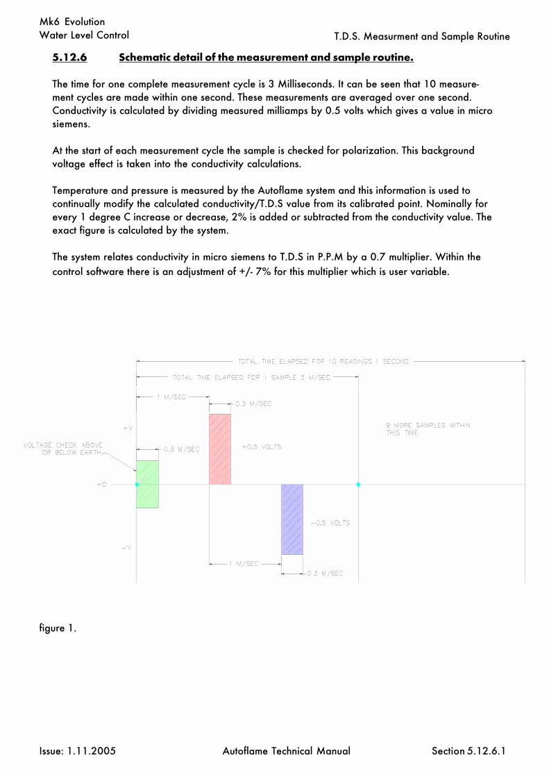
Water Level Control
Issue: 1.11.2005 Autoflame Technical Manual Section
Mk6 Evolution
5.12.6 Schematic detail of the measurement and sample routine.
The time for one complete measurement cycle is 3 Milliseconds. It can be seen that 10 measure-ment cycles are made within one second. These measurements are averaged over one second.Conductivity is calculated by dividing measured milliamps by 0.5 volts which gives a value in microsiemens.
At the start of each measurement cycle the sample is checked for polarization. This backgroundvoltage effect is taken into the conductivity calculations.
Temperature and pressure is measured by the Autoflame system and this information is used tocontinually modify the calculated conductivity/T.D.S value from its calibrated point. Nominally forevery 1 degree C increase or decrease, 2% is added or subtracted from the conductivity value. Theexact figure is calculated by the system.
The system relates conductivity in micro siemens to T.D.S in P.P.M by a 0.7 multiplier. Within thecontrol software there is an adjustment of +/- 7% for this multiplier which is user variable.
figure 1.
5.12.6.1
T.D.S. Measurment and Sample Routine

Water Level Control
Issue: 1.11.2005 Autoflame Technical Manual Section
Mk6 Evolution
÷
figure 3.
Once the T.D.S software has calculated the average T.D.S value for the 10 samples within onesecond, it will then extract these averages and add the last 10 together and divide them by ten togive the actual T.D.S reading as shown in figure 3. This value will be displayed on the MM.
When a new average of the 1 second samples is obtained the software will utilize the last 9 aver-ages, It will then add the new average to them and divide it by 10 to obtain the new T.D.S value.
figure 2.
The T.D.S system logs each of the samples within the 1 second time period, It takes all 10 samplevalues, adds them together then divides them by 10 to obtain the average T.D.S value for the onesecond period as illustrated in figure 2.
÷
5.12.6.2
T.D.S. Measurment and Sample Routine

Water Level Control
Issue: 1.11.2005 Autoflame Technical Manual Section
Mk6 Evolution
5.12.7 Relationship between Conductivity, Temp and T.D.S values.
A = These values measured by probe & sensors at operating steady state conditions.B = This value is conductivity value multiplied by 0.7 (TDS in PPM)C= This conductivity value temperature corrected to 25 degrees C / 77 degrees F.D= This is measured T.D.S value entered into the system to effect a user “calibration”.
1) Conductivity measurement corrected at 2% per 1 degree C.2) At 25 degrees C T.D.S in PPMv is calculated by multiplying the conductivity value by 0.7.3) Both of the above multipliers are user variable to accommodate specific site conditions.
5.12.7
T.D.S. Information

Water Level Control
Issue: 1.11.2005 Autoflame Technical Manual Section
Mk6 Evolution
1: At the time of manufacture every T.D.S. probe has buried in its electronics memory a “CalibrationCorrection Coefficient” or C.C.C. This is effected as set out under.
The T.D.S probe in a sampling vessel is immersed in a boiler water sample of a known T.D.S (i.e.3500 ppm for example). This is carried out at 25 degrees C (77 degrees F) which would give areading in microsiemens of 5000. If the reading off of the probe electronics does not agree with thisa correction multiplier or divider is implanted into this specific probes electronic memory. This is itsown dedicated C.C.C value.
2: The perfect solution for T.D.S control would be that the minimum amount of surface blowdown iscarried out to keep the dissolved solids at or below the nominated value set on the controller. Itfollows that the amount of surface blowdown required is directly proportional to the evaporationrate and therefore the firing rate of the boiler/burner unit.
If for example the boiler is operating at a steady state rate of 50% evaporation the amount ofblowdown time would have to be doubled at 100% rate or M.C.R and halved if working at 25% or4:1 turn down. There is an option within the software to enable this facility which will guaranteethat minimum energy is lost to surface blowdown while ensuring sufficient blowdown is implementedto keep T.D.S levels at the desired value. This is possible because the Autoflame system knows thefiring rate of the burner.
5.12.7
T.D.S. Information

Water Level Control
Issue: 1.11.2005 Autoflame Technical Manual Section
Mk6 Evolution
5.12.8
T.D.S. Probe and Sampling Vessel
5.12.8 T.D.S Probe and Autoflame Sampling Vessel

Water Level Control
Issue: 1.11.2005 Autoflame Technical Manual Section
Mk6 Evolution
5.12.9 Top Blow Down Management
The day to day Top Blow Down Management user screen is shown below. The system will open the topblow down valve on an intelligently timed basis such that the MEASURED value of Total Dissolved Solids(TDS) is maintained at or just below the TARGET value. The screen is selected by means of the WATERLEVEL button and appears next after the Bottom Blow Down screen. The screen will only be displayedif Water Level setup 23.1 is set to Enabled.
At the bottom of the screen the various stages of top blow down are displayed as they occur, with a downcounter indicating the number of seconds left for this stage. When the Top Blow Down is operating thepossible messages are:
BLOW DOWN MEASURESETTLEMENTMEASUREMENTBLOW DOWNINTERVAL
If the burner is not firing the following is displayed:TOP BLOW DOWN NOT OPERATINGBURNER NOT FIRING
If the buner is firing and steam pressure is not up to the Threshold Offset the following is displayed:TOP BLOW DOWN NOT OPERATINGSTEAM PRESSURE BELOW THRESHOLD
If there is no data being received from the TDS probe following is displayed:TOP BLOW DOWN NOT OPERATINGWARNING PROBE FAULT
Setting up Procedure: Top Blow Down Management
5.12.9

Water Level Control
Issue: 1.11.2005 Autoflame Technical Manual Section
Mk6 EvolutionSetting up Procedure: Set T.D.S. Target Value
5.12.9.2 Adjustment of T.D.S. Target Value
Whilst the day to day Top Blow Down Management screen is being displayed press the COM buttonfor 2 seconds. The SET TDS TARGET VALUE screen shown below will be displayed. The WATER LEVEL& COM leds will be on & the RUN led flashing. Use the channel 3 UP/DOWN buttons to adjust theTARGET value units. The channel 5 UP/DOWN buttons can also be used to change the value by 10s.Note while in this screen there is no top blown down operation. Press RUN to go back to normaloperation. When the run button is pressed the new TARGET value is stored in memory.
5.12.9.2

Water Level Control
Issue: 1.11.2005 Autoflame Technical Manual Section
Mk6 EvolutionSetting up Procedure: Probe Calibration
5.12.9.3 T.D.S. Probe Calibration
If it is deemed necessary to adjust the TDS probe calibration proceed as follows.
Whilst the day to day Top Blow Down Management screen is being displayed press the COM buttonfor 2 seconds so that the SET TDS TARGET VALUE screen is shown. The WATER LEVEL & COM leds willbe on & the RUN led flashing. Press the Water Level button once. The PROBE CALIBRATION screenshown below should be displayed. Note while in this screen there is no top blown down operation. Pressthe channel 6 UP/DOWN buttons simultaneously to invoke a single BLOW DOWN MEASUREsequence to bring new boiler water sample into the TDS probe measurement chamber. If necessaryrepeat this process until a stable reading is produced. Use the channel 3 UP/DOWN buttons to fineadjust the MEASURED value. The channel 5 UP/DOWN buttons can also be used to provide a coarseadjustment. Adjust the value a little at a time - it takes one or two seconds for the value to respond tothe change. If the value overshoots adjust back as necessary. Press RUN to return to normal operation.When the run button is pressed the corrected reading is stored in memory.
5.12.9.3

Water Level Control
Issue: 1.11.2005 Autoflame Technical Manual Section
Mk6 Evolution
5.12.9.4 Top Blow Down Adjusters
The Top Blow Down Adjusters allow the Top Blow Down Operation to be adjusted to suit boiler runconditions.
Whilst the day to day Top Blow Down Management screen is being displayed press the COM buttonfor 2 seconds so that the SET TDS TARGET VALUE screen is shown. The WATER LEVEL & COM leds willbe on & the RUN led flashing. Press the Water Level button twice. The ADJUSTERS screen shown belowshould be displayed. Note while in this screen there is no top blown down operation.
Use the channel 2 UP/DOWN buttons to select the item to be adjusted EG Sample Interval Time. Usethe channel 3 UP/DOWN buttons to adjust the value units. Where appropriate the channel 5 UP/DOWN buttons can also be used to change the value by 10s. Press RUN to return to normal operation.When the run button is pressed all Adjuster values are stored in memory.
Setting up Procedure: Top Blow Down Adjusters
5.12.9.4

Water Level Control
Issue: 1.11.2005 Autoflame Technical Manual Section
Mk6 Evolution
60
60
Disabled
0.70
Disabled
NO
ppm
0
0-300
5-1500
Disabled1-100%
enableddisabled
0.50-1.50
Disabled1-50PSI
1-5.0BAR
NOYES
ppmuS
0-1-
5.12.9.5
Setting up Procedure: Top Blow Down Adjusters
Facto
ry Setti
ng
Setup V
alue
Descrip
tion
Blow Down Time: Time the Top Blow Down valve is opened for.
Interval Time: Time between Top Blow Down samples.
Load Dependant Blow Down Timing: If disabled not effected. Valueentered is a load index reference point - ideally the load index point atwhich the Top Blow Down operation was set up.For example: set to 50%. When the top Blow Down takes place if thecurrent load index postion is 100% the Blow Down Time will be doubled.(100/50). If at 25% the Blow Down Time will be halved (25/50). Notethe Load Index must be entered before Top Blow Down is commisioned.(See Options 57&65)
MicroSiemens To TDS Factor: The TDS probe measures conductivityin microSiemens. This factor is used to derive the TDS value in ppm. EG5000uS * 0.7 = 3500 ppm.
Steam Pressure Threshold Offset Below Required: If the MMACTUAL value is less than the REQUIRED value minus this offset then theTop Blow Down does not operate.For example: Required = 100PSI Offset value = 10PSI. Top Blow Downstarts to operate when steam pressure reaches 90PSI. Once thisthresholdis met after the burner fires Top Blow Down stays operating even if thepresure drops below thereafter.
Reset defaults: Resets all adjusters to default values & TDS probe topreset calibration. Select YES then press RUN.
Sets ppm or microsiemens (uS):ppmmicrosiemens
HIgh limit alarm:Disabled.Enabled- value set is an offset above the target value at which alarmtrips.
Note: Once the limit has been exceeded terminal #79 will be set, thetop blowdown screen will be displayed and the water level LED willflash. Press the water level button to mute the alarm. The alarm limitvalue will flash until the measured TDS value has fallen below the limitvalue. Another alarm will not be generated until the measured TDSvalue has been continuously below the limit value for 10 minutes.

Water Level Control
Issue: 1.11.2005 Autoflame Technical Manual Section
Mk6 Evolution
INTERVAL TIME 5 - 1500 SEC
BLOWDOWN MEASURE5 SEC
SETTLEMENT TIME5 SEC
MEASUREMENT TIME5 SEC
BLOWDOWN TIME0 - 300 SEC
SETTLEMENT TIME5 SEC
MEASUREMENT TIME5 SEC
CALL FOR HEAT
MEASURED VALUE< TARGET VALUE
YES
NO
MEASURED VALUE< TARGET VALUE
YES NO
5.12.9.6
T.D.S. Timing Diagram
5.12.9.6 T.D.S. Timing Diagram

Water Level Control
Issue: 1.11.2005 Autoflame Technical Manual Section
Mk6 Evolution

D.T.I. Data Transfer Interface
Issue: 1.11.2005 Autoflame Technical Manual Section
Section 6: D.T.I. Data Transfer Interface
6.1 DTI Module
6.2 Information Available from the DTI system
6.3 Complete DTI Standard System Application Example
6.4 Multi Kiln DTI Special System Application Example
6.5 Front Facia Layout
6.7 I/O System Capabilities
6.8 Communication Interface schematic system capabilities
6.9 Wiring Connection Terminals Diagram
6.10 DTI Fixing Holes and Dimensional Details
6.11 DTI Interconnections
6.11.1 MM Modules6.11.2 EGA Modules
6.12 PCB Switch Settings and Link Arrangements
6.12.1 Restore To Factory Settings
6.13 DTI, PC and Modem Interconnections
6.14 Analogue Input/Output Module Index
6.15 Digital Input/Output Module Index
6.17 Modbus Interface Index
6.18 Autoflame WinPCDTI Software
6.19 Johnson Metasys Interface Index
6.20 Other Information and Illustrations
6.20.1 Loop Back Test6.20.2 Communication Interfaces
6 Index

D.T.I. Data Transfer Interface
Issue: 1.11.2005 Autoflame Technical Manual Section
6.1 DTI MODULE
6.1
Introduction

D.T.I. Data Transfer Interface
Issue: 1.11.2005 Autoflame Technical Manual Section
MM Information:
Required boiler temperature (deg. C) or pressure (Bar).Actual boiler temperature (deg. C) or pressure (Bar).Burner on/off (CR relay on/off status).Burner maximum firing rate.Burner firing rate (%).Fuel selected.Control detector type (temperature/pressure).Error conditions.Low flame hold operation.Hand operation.Channel 1-Channel 8, CH1-CH8 Positioning Motors (Angular Deg.)Maximum set point accepted from DTI.Minimum set point accepted from DTI.Lead boiler status.Burner firing status (off, firing, purge, ignition).Sequencing optioned.Sequence status (on, stand-by, warm, off).Enabled/disabled status.
EGA Information:
EGA operation optioned.Flue gas oxygen present value.Flue gas carbon dioxide present value.Flue gas carbon monoxide (unburnt combustibles) present value.Flue gas exhaust temperature present value.Combustion efficiency present value.Flue gas oxygen commission value.Flue gas carbon dioxide commission value.Flue gas carbon monoxide (unburnt combustibles) commission value.Flue gas exhaust temperature commission value.Combustion efficiency commission value.EGA error conditions.
DTI Input values:
Boiler enable/disable.Change required set point.Select lead boiler.Shuffle Sequencing.Set Load Inedex.
6.2 INFORMATION AVAILABLE FROM THE DTI
DTI Information:
6.2.1
Information

D.T.I. Data Transfer Interface
Issue: 1.11.2005 Autoflame Technical Manual Section
Water Level Information:
Actual Water LevelEnd of probe position2nd low position1st low position1st low pre-alarm positionControl point position or pump on and pump off positionsHigh water pre-alarm positionHigh water position15 First Out Annunciation inputs statusInstantaneous steam flow meteringTotalised steam flow meteringFeed water temperatureSteam temperature
Continuous Emissions Monitoring Software (CEMS):
Current emissions by weight and volume (O2, CO2, CO, NO, SO2, H2O, N2, Total)Totalised emissions by weight (O2, CO2, CO, NO, SO2, H2O, N2, Total)EfficiencyExhaust temperatureBoiler exit velocityTotal heat input into boilerNet useful heat into boilerHeat loss to stackFuel flow
DTI Information:
6.2.2
Information

D.T.I. D
ata Transfer Interface
Issue: 1.11.2005A
utoflame Technical M
anualSection
BOILER No.3BOILER No.2
D.T.I. UNIT
Mk.6 M.M.
MK.6 E.G.A. MK.6 E.G.A. MK.6 E.G.A.
PC
ANALOGUEI/O UNIT
DIGITALI/O UNIT
BOILER No.4
ANALOGUEI/O UNIT
DIGITALI/O UNIT
Com
plete DTI Standard System
Application Exam
ple
6.3
BOILER No.1
MK.6 E.G.A.
Mk.6 M.M. Mini Mk.6 M.M. Mini Mk.5 M.M.

D.T.I. D
ata Transfer Interface
Issue: 1.11.2005A
utoflame Technical M
anualSection
6.4
KILN No.2
4 X
THER
MO
CO
UPL
ES
Mini Mk.5 M.M.
KILN No.14
X TH
ERM
OC
OU
PLES
OTHERCONTROL
X 8
ALARMSX 16
DIGITALI/O UNIT
DTI UNIT
ANALOGUEI/O UNIT
BURNER RATE SIGNALKILN No.1
BURNER RATE SIGNALKILN No.2
PC
Multi K
iln Special System A
pplication Example
Mini Mk.5 M.M.
ANALOGUEI/O UNIT
Mini Mk.5 M.M.
Mini Mk.5 M.M.Mini Mk.5 M.M.
Mini Mk.5 M.M.Mini Mk.5 M.M.
Mini Mk.5 M.M.

D.T.I. Data Transfer Interface
Issue: 1.11.2005 Autoflame Technical Manual Section
6.5 FRONT FACIA LAYOUT
6.5
DTI Front Facia Layout

D.T.I. Data Transfer Interface
Issue: 1.11.2005 Autoflame Technical Manual Section
6.7 INPUT/OUTPUT SYSTEM CAPABILITIES
6.7
Input/Output System Capabilities

D.T.I. Data Transfer Interface
Issue: 1.11.2005 Autoflame Technical Manual Section 6.8
6.8 COMMUNICATION INTERFACE SCHEMATIC SYSTEM CAPABILITIES
Communication Interface Schematic System Capabilities

D.T.I. Data Transfer Interface
Issue: 1.11.2005 Autoflame Technical Manual Section
6.9 WIRING CONNECTION TERMINALS DIAGRAM
6.9
EARTHSUPPLY NEUTRAL
SUPPLY LIVE
MM SCREENMM NEGATIVE -MM POSITIVE +
EGA SCREENEGA NEGATIVE -EGA POSITIVE +
RS 485 POSITIVE +RS 485 NEGATIVE -RS 485 SCREEN
I/O POSITIVE +I/O NEGATIVE -I/O SCREEN
RS 422 TX +RS 422 TX -RS 422 RX +RS 422 RX -RS 422 SCREEN
PC
Wiring Connection Terminals Information Diagram
MODEM

D.T.I. Data Transfer Interface
Issue: 1.11.2005 Autoflame Technical Manual Section
6.10 DTI FIXING HOLES AND DIMENSIONS
6.10
DTI Fixing Holes and Dimensional Details

D.T.I. Data Transfer Interface
Issue: 1.11.2005 Autoflame Technical Manual Section 6.11.2
6.11.2 EGA Modules (Standalone EGA)
MM/EGA and DTI Interconnections

D.T.I. Data Transfer Interface
Issue: 1.11.2005 Autoflame Technical Manual Section
6.12 PCB SWITCH SETTINGS
PCB Switch Settings
6.12
Standard DTI - when used with WinPCDTI Software
Switch Bank 1 - not relevant, set to 001
Switch Bank 2 - ways 1 to 7 all set to off
Way 8 MM Port Baud Rateoff - 9600 (Mk6, Mini Mk6 and Mini Mk5 MMs)on - 4800 (Older Mk5 and Mini MMs)*
* Technical Memo: Data Communication Compatibility 3/9/1999
Settings for switch banks 1 & 2 may be different if the DTI is used for both WinPCDTI and Modbus/Metasys operation. See sections 6.17.6.
ON
OFF1 2 3 4 5 6 7 8
Switch Bank 1 Switch Bank 2
10s100s 1s

D.T.I. Data Transfer Interface
Issue: 1.11.2005 Autoflame Technical Manual Section 6.12.1
6.12.1 To Restore Factory Settings
This procedure clears all congifuration data in the DTI and sets it back to default settings. (Configurationdata includes, for example, alarm trigger conditions and labels).
Procedure
1. Power off the unit.
2. Set Switch Bank 1 address value to 789:100s = 710s = 81s = 9
(Switch Bank 2 settings are irrelevant).
3. Power up.
4. Wait until the I/O transmit LED flashes (approx. 25 seconds)
5. Power off.
6. Set switches back to the required operational settings.
7. Power on unit.
PCB Switch Settings
Switch Bank 1
10s100s 1s

D.T.I. Data Transfer Interface
Issue: 1.11.2005 Autoflame Technical Manual Section
6.13 DTI, PC AND MODEM INTERCONNECTIONS
6.13.1
DTI, PC and Modem Interconnections
Connection between PC and DTI MODEM
Connection between PC and DTI RS-422 port
Example shown using line drive typeGW232F made by Greenwich InstrumentsLimited.

D.T.I. Data Transfer Interface
Issue: 1.11.2005 Autoflame Technical Manual Section 6.13.2
DTI, PC and Modem Interconnections
Direct connection between PC and DTI RS-232 PC port
PC-DTI Cable (for older DTI units that do not use a standard PC serial lead)
D.T.I. Data Transfer Interface
Issue: 1.11.2005 Autoflame Technical Manual Section
Section 6.14: Analogue Input/Output Module Index
6.14.1 Introduction, Features & Benefits
6.14.2 Facia Layout and Internal Connections
6.14.3 Setup Configuration for direct connection to M.M. unit
6.14.4 Front Facia Layout with LED description
6.14.5 Fixing Holes & Dimensional Details
6.14.6 Wiring Connection Diagram
6.14.7 M.M. to Analogue Input/Output Unit Connection Diagram
6.14.8 DTI to Analogue Input/Output Unit Connection Diagram
6.14.9 Application Example
6.14 Index
D.T.I. Data Transfer Interface
Issue: 1.11.2005 Autoflame Technical Manual Section
This unit has 6 analogue inputs and 6 analogue outputs. Each analog input can be individually configuredfor 0-10 Volts, 0-20milliamps or 4-20 milliamps. Each analog output can be individually configuredfor 0-10 Volts or 4-20 milliamps. The unit is primarily for use with a Data Transfer Interface (DTI) unit.It can also be used in conjunction with most MM units to convert MM items of data to analogueoutputs. Before operation the unit must be setup for its particular modes of operation by means of aserial port and a personal computer (emulating a terminal - e.g. Windows Hyperterminal). Each ana-log input and output must also have a jumper set to select voltage or current operation.
When used with a DTI up to 10 analogue input/output units can be linked together. As well as theactual analogue inputs and outputs being configurable, the data range for each input and output canalso be individually set. Text labels can also be assigned to each input and output. The latter items(data range / text labels) can be of use when the DTI is being used for a building management systemor programmable logic controller type interface. However, in the vast majority of cases, these setupscan be left as supplied. Refer to DTI manual for interconnections between the Analogue I/O unit & theDTI.
An external PSU is not required for the analogue outputs. The maximum permissable load on each analogueoutput is 250Ω. All the negative terminals are common to each other. The analogue outputs as a wholeare isolated.
6.14.1 Introduction , Features and Benefits
6.14.1
Analogue I/O Module

D.T.I. Data Transfer Interface
Issue: 1.11.2005 Autoflame Technical Manual Section
SCREENNEGATIVE -POSITIVE +
ANALOGUEINPUT 1
SCREENNEGATIVE -POSITIVE +
ANALOGUEINPUT 2
SCREENNEGATIVE -POSITIVE +
ANALOGUEINPUT 3
SCREENNEGATIVE -POSITIVE +
ANALOGUEINPUT 4
SCREENNEGATIVE -POSITIVE +
ANALOGUEINPUT 5
SCREENNEGATIVE -POSITIVE +
ANALOGUEINPUT 6
POSITIVE +NEGATIVE -SCREENPOSITIVE +NEGATIVE -SCREEN
ANALOGUEOUTPUT 5
POSITIVE +NEGATIVE -SCREEN
ANALOGUEOUTPUT 4
POSITIVE +NEGATIVE -SCREENPOSITIVE +NEGATIVE -SCREEN
ANALOGUEOUTPUT 2
POSITIVE +NEGATIVE -SCREEN
ANALOGUEOUTPUT 1
EARTHSUPPLY NEUTRALSUPPLY LIVE
I/O SCREENI/O NEGATIVE -I/O POSITIVE +
RS485 TO D.T.I.
ANALOGUEOUTPUT 6
ANALOGUEOUTPUT 3
6.14.2 Facia Layout and Internal Connections
6.14.2
N.B. All Negative connections are common to each other.
Analogue I/O Module

D.T.I. Data Transfer Interface
Issue: 1.11.2005 Autoflame Technical Manual Section
SETUP
To configure the unit connect a pc serial port to the setup port (use the Autoflame I/O setup lead). Thepc must be running a terminal emulation program with the transmit and receive parameters set asfollows:
Baud rate: 4800Data bits 8Parity noneStop bits 1
(Check the COM port is set to the one actually being used).
Pressing the <return> key should bring up the following opening message:
Analog I/O unit setup mode
Pressing the <ESC> key at any time during setup will cause exit from setup. If no keys are pressed fora period of approximately 5 minutes the unit will automatically exit from setup and revert to normaloperation. During setup the unit will not carry out its normal functions. A test mode can be invokedduring set up so the operation of the inputs and outputs can be checked. Every detail of the setup is notcovered here as it is very repetitive. Experience can be quickly gained by working with an actual unitin setup mode. (Note that during normal operation if the PC is connected textual messages are dis-played indicating communication between input/output units and the DTI).
If an existing setting is to be left unchanged then just press the <return> key.
The following shows samples of the various items that can be set. Text that is displayed on the screenis shown in bold.
Present input range for analog input 1 is A 0-10 volts
Ranges available0 - 10 volts A0 - 20 milliamps B4 - 20 milliamps C
Make new selection or <return>This can be set for all 6 inputs. The appropriate link on the circuit board must be set for current/voltage. The link for each input is directly behind the 3 way terminal block.
Present mode of operation is with DTIPress M to set MM mode or <return to proceed>
If DTI mode is selected, by just pressing <return> in this example, the following items are displayed
6.14.3 Setup Configuration for direct connection to M.M. unit
6.14.3
Analogue I/O Module

D.T.I. Data Transfer Interface
Issue: 1.11.2005 Autoflame Technical Manual Section
Address is currently set to 1
Press <return> or enter new address(1-10) then <return>:
the address must be set in sequence for each analog I/O unit. e.g. if there are 3 analogue I/O unitson the system the first should be set address 1, the second to address 2, the third to address 3.Conflicts will occur if addresses are not set correctly.
Input number 1:-Present label : Analog Input 1Enter new label : Up to 30 alpha numeric characters can be used for a label
Present low range digital value : 0Enter new low range value : This is the low data range value, it must be in the range 0-255
Present high range digital value : 255Enter new high range value : This is the high data range value, it must be in the range 0-255
The label, low range and high range values can be set for all 6 inputs and all 6 outputs. After theouput 6 high range value the setup mode is exited and the following appears on the screen
SETUP TERMINATED !
operation will revert to normal.
If the MM mode of operation is selected then the following items are displayed
Firing rate ARequired value BActual value CChannel 1 position DChannel 2 position EChannel 3 position FChannel 4 position GMM error HEGA error IO2 value JCO2 value KCO value LNO value MSO2 value NExhaust Temperature OEfficiency P
Present selection for analogue output 1 is : A - Firing ratePresent low range value : 0Present high range value : 100
6.14.3.1
Analogue I/O Module
D.T.I. Data Transfer Interface
Issue: 1.11.2005 Autoflame Technical Manual Section 6.14.3.2
if the <return> key is pressed the screen refreshes with the same display but for analogue output 2. Ifa selection is made then a low range value and a high range value are subsequently requested.The low and high range values are values at which the output ranges itself from zero to span (ie 0-10volts or 4-20 milliamps). After all 6 analog outputs have been covered the setup mode isautomatically exited and the screen displays
SETUP TERMINATED !
It must be noted that the numeric values for the low and high range do not accept decimal points. If thevalue normally has a decimal point then the value should be entered without the decimal point. (e.g.for the channel 2 position, if the output was set to give 0-10 volts over 10.0 to 80.0 degrees then thelow and high range should be entered as 100 and 800 respectively.
Analogue I/O Module
Configuration of MM when used directly with an Analogue I/O unit
If an analog I/O unit is connected directly to an MM to provide analog outputs, the first analogueinput may be used to set the Required value. (Input channels 2 to 6 are of no relevance when the unitis used with an MM).
If the Required value is to be set by the channel 1 input then the following options/parameters shouldbe set on the MM.
Option 16 = 2Option 30 = lowest Required valueOption 31 = highest Required valueOption 33 = 1Parameter 49 = 1
The channel 1 input can be configured for voltage/current as described in the earlier sections of thesetup procedure.
On later versions of the Analogue I/O unit software (3.01 onwards) there is an additional set up to setthe type of MM connected.
Example:
RS485 port baud rate is set at 9600 (Mk6, MiniMk6, MiniMk5)Press 4 for to set to 4800 <return> to proceed.
Also on the later versions the following text is displayed when not in set up mode.
MM comms = nnn required value = nnn
MM comms increments each time the Analogue I/O unit receives data from the MM. Required valueis the value that has been calculated for transmission back to the MM.
NB: Sequencing/D.T.I. and Analogue I/O unit cannot be used at the same time.

D.T.I. Data Transfer Interface
Issue: 1.11.2005 Autoflame Technical Manual Section
6 X
4 -2
0m
A -
0 -1
0V
- I/
OPa
rt N
o. D
TI20
021
6 Ch
ann
el In
put
6 Ch
ann
el O
utp
ut
Rx Tx Pow
er
O.K
.
6.14.4 Front Facia Layout with LED Description
6.14.4
Analogue I/O Module

D.T.I. Data Transfer Interface
Issue: 1.11.2005 Autoflame Technical Manual Section
6.14.5 Fixing Holes & Dimensional Details
6.14.5
Analogue I/O Module
The depth of the unit is 38mm (1.5").These units are back plate mounted not mounted on the front.

D.T.I. Data Transfer Interface
Issue: 1.11.2005 Autoflame Technical Manual Section
6.14.6 Wiring Connections Diagram
6.14.6
Analogue I/O Module

D.T.I. Data Transfer Interface
Issue: 1.11.2005 Autoflame Technical Manual Section
6.14.7 M.M. to Analogue Input/Output Unit Connection Diagram
6.14.7
Analogue I/O Module

D.T.I. Data Transfer Interface
Issue: 1.11.2005 Autoflame Technical Manual Section
6.14.8 DTI to Analogue Input/Output Unit Connection Diagram
6.14.8
Analogue I/O Module
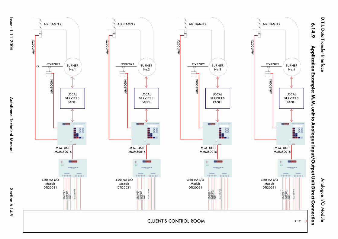
D.T.I. D
ata Transfer Interface
Issue: 1.11.2005A
utoflame Technical M
anualSection
CLLIENT'S CONTROL ROOM X 12
6.1
4.9
Ap
plica
tion Ex
am
ple: M
.M. unit to
Ana
log
ue Input/O
utput U
nit Direct Co
nnection
6.14.9
FUEL
PO
SITI
ON
AIR
PISI
TIO
NFI
RIIN
G R
ATE
ERRO
R /
FAU
LTSP
ARE
SPA
RE
LOA
D C
ON
TRO
L
4-20 mA i/OModule
DTI20021
M.M. UNITMMM50016
LOCALSERVICES
PANEL
MM
1000
4
MM
1007
2
BURNERNo.1
OV37021OIL
AIR DAMPER
FUEL
PO
SITI
ON
AIR
PISI
TIO
NFI
RIIN
G R
ATE
ERRO
R /
FAU
LTSP
ARE
SPA
RE
LOA
D C
ON
TRO
L
4-20 mA i/OModule
DTI20021
M.M. UNITMMM50016
LOCALSERVICES
PANEL
MM
1000
4
MM
1007
2
BURNERNo.2
OV37021
AIR DAMPER
FUEL
PO
SITI
ON
AIR
PISI
TIO
NFI
RIIN
G R
ATE
ERRO
R /
FAU
LTSP
ARE
SPA
RE
LOA
D C
ON
TRO
L
4-20 mA i/OModule
DTI20021
M.M. UNITMMM50016
LOCALSERVICES
PANEL
MM
1000
4
MM
1007
2
BURNERNo.3
OV37021
AIR DAMPER
FUEL
PO
SITI
ON
AIR
PISI
TIO
NFI
RIIN
G R
ATE
ERRO
R /
FAU
LTSP
ARE
SPA
RE
LOA
D C
ON
TRO
L
4-20 mA i/OModule
DTI20021
M.M. UNITMMM50016
LOCALSERVICES
PANEL
MM
1000
4
MM
1007
2
BURNERNo.4
OV37021
AIR DAMPER
Analogue I/O
Module

D.T.I. Data Transfer Interface
Issue: 1.11.2005 Autoflame Technical Manual Section
Section 6.15: Digital Input/Output Module Index
6.15 Index
6.15.1 Introduction, Features & Benefits
6.15.2 Facia Layout and Internal Connections
6.15.3 Setup Configuration for direct connection to DTI unit only
6.15.4 Front Facia Layout with LED Description
6.15.5 Fixing Holes & dimensional Details
6.15.6 Wiring Connection Diagram
6.15.7 DTI to Digital Input/Output Unit Connection Diagram

D.T.I. Data Transfer Interface
Issue: 1.11.2005 Autoflame Technical Manual Section
This unit has 16 mains voltage inputs and 8 individual volt free mains voltage switches.The unit is used in conjunction with a Data Transfer Interface (DTI) unit. Before operation the unit mustbe setup for operation by means of a serial port and a personal computer (emulating a terminal). Aspecial lead supplied by Autoflame is required to connect the personnel computer to the unit. Up to10 digital input/output units can be chained together.Text labels can also be assigned to each inputand output. The latter items (data range / text labels) can be of use when the DTI is being used for abuilding management system or programmable logic controller type interface.Refer to DTI manual for interconnections between the Analogue I/O unit & the DTI
6.15.1 Introduction , Features and Benefits
6.15.1
Digital I/O Module

D.T.I. Data Transfer Interface
Issue: 1.11.2005 Autoflame Technical Manual Section
COMMONINPUT 1INPUT 2INPUT 3INPUT 4INPUT 5INPUT 6INPUT 7INPUT 8INPUT 9
INPUT 10INPUT 11INPUT 12INPUT 13INPUT 14INPUT 15INPUT 16
SUPPLY LIVESUPPLY NEUTRALEARTH
OUTPUT 8
OUTPUT 7
OUTPUT 6
OUTPUT 5
OUTPUT 4
OUTPUT 3
OUTPUT 2
OUTPUT 1
I/O SCREENI/O NEGATIVE -I/O POSITIVE +
RS485 TO D.T.I.
6.15.2 Facia Layout and Internal Connections
6.15.2
Digital I/O Module

D.T.I. Data Transfer Interface
Issue: 1.11.2005 Autoflame Technical Manual Section
To configure the unit connect a pc serial port to the setup port (use the Autoflame I/O setup lead).The pc must be running a terminal emulation program with the transmit and receive parameters setas follows:
Baud rate: 4800Data bits 8Parity noneStop bits 1
(Check the COM port is set to the one actually being used).
Pressing the <return> key should bring up the following opening message:
Digital I/O unit setup mode
Pressing the <ESC> key at any time during setup will cause exit from setup. If no keys are pressedfor a period of approximately 5 minutes the unit will automatically exit from setup and revert tonormal operation. During setup the unit will not carry out its normal functions. A test mode can beinvoked during set up so the operation of the inputs and outputs can be checked. Every detail of thesetup is not covered here as it is very repetitive. Experience can be quickly gained by working withan actual unit in setup mode. (Note that during normal operation if the pc is connected textualmessages are displayed indicating communication between input/output units and the DTI).
If an existing setting is to be left unchanged then just press the <return> key.
The following shows samples of the various items that can be set. Text that is displayed on thescreen is shown in bold.
Address is currently set to 1
Press <return> or enter new address(1-10) then <return>:
The address must be set in sequence for each digital I/O unit. e.g. if there are 3 digital I/O units onthe system the first should be set address 1, the second to address 2, the third to address 3. Conflictswill occur if addresses are not set correctly
Input number 1:-Present label : Digital Input 1Enter new label : Up to 30 alpha numeric characters can be used for the label
Present Monitor/Alarm status is : MonitorEnter M/A or <return to proceed>
Present Active High/Low status is : HighEnter H/L or <return> to proceed
The label, M/A status and H/L status are repeated for all 16 inputs.
6.15.3 Setup configuration for direct connection to D.T.I. unit
6.15.3
Digital I/O Module

D.T.I. Data Transfer Interface
Issue: 1.11.2005 Autoflame Technical Manual Section
Output number 1:-Present label : Digital Output 1Enter new label : Up to 30 alpha numeric characters can be used for the label.
The label entry is repeated for all eight outputs. After all 8 digital outputs have been covered thesetup mode is automatically exited and the screen displays
SETUP TERMINATED !
6.15.3.1
Digital I/O Module

D.T.I. Data Transfer Interface
Issue: 1.11.2005 Autoflame Technical Manual Section
Rx Tx Pow
er
O.K
.
8 X
Vo
lt F
ree
Out
put
s -
16
X L
ine
Inp
uts
Part
No.
DTI
2002
0
Out
put
s8
X V
olt
Fre
e Co
nta
cts
Inp
uts
16
X 2
30
V/1
10
V In
put
s
6.15.4 Front Facia Layout with LED Description
6.15.4
Digital I/O Module

D.T.I. Data Transfer Interface
Issue: 1.11.2005 Autoflame Technical Manual Section
6.15.5 Fixing holes & Dimensional Details
6.15.5
Digital I/O Module
The depth of the unit is 38mm (1.5").These units are back plate mounted not mounted on the front.
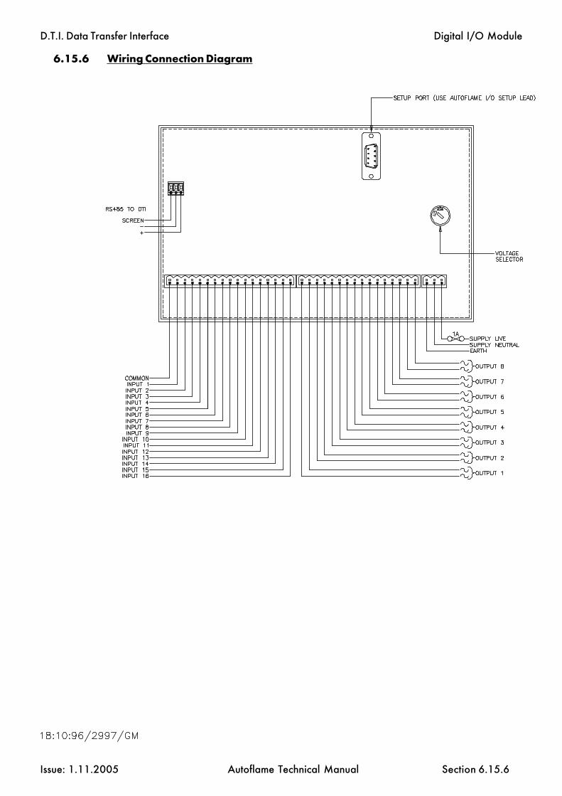
D.T.I. Data Transfer Interface
Issue: 1.11.2005 Autoflame Technical Manual Section
6.15.6 Wiring Connection Diagram
6.15.6
Digital I/O Module

D.T.I. Data Transfer Interface
Issue: 1.11.2005 Autoflame Technical Manual Section
6.15.7 DTI to Digital Input/Output Unit Connection Diagram
6.15.7
Digital I/O Module

D.T.I. Data Transfer Interface
Issue: 1.11.2005 Autoflame Technical Manual Section
Section 6.17: Modbus Interface Index
6.17 Index
6.17.1 Overview
6.17.2 OX References - coils
6.17.2.1 Enable/Disable commands for each M.M6.17.2.2 Digital Input/Output module outputs
6.17.3 1X References - Inputs
6.17.3.1 Digital Input/Output module6.17.3.2 M.M. System6.17.3.3 E.G.A. System6.17.3.4 Online Offline Status
6.17.4 3X References - Input Registers
6.17.4.1 Analogue Input/Output module6.17.4.2 M.M. System6.17.4.3 E.G.A. System
6.17.5 4X References - Holding Registers
6.17.5.1 M.M. System6.17.5.2 Analogue Input/Output module outputs
6.17.6 PCB Switch Settings
6.17.7 Other Information
6.17.7.1 Modbus Transmission Serial Port Settings6.17.7.2 Supported Commands6.17.7.3 Supported Exception Responses6.17.7.4 Serial Port Connections
6.17.8 Relevance of MM/EGA Data
6.17.9 Further Information

D.T.I. Data Transfer Interface
Issue: 1.11.2005 Autoflame Technical Manual Section 6.17.1
6.17.1 Overview
This manual details information regarding the Data Transfer Interface (DTI) 'Modbus' type interface.This interface allows the DTI to simultaneously communicate with the standard Autoflame Windows95 PCDTI System.
Some knowledge of the Micro Modultion system is necessary to appreciate the meaning of the infor-mation contained within this manual.
Modbus

D.T.I. Data Transfer Interface
Issue: 1.11.2005 Autoflame Technical Manual Section 6.17.2
6.17.2 0X Reference Addresses - Coils
6.17.2.1 Enable/Disable command for each MM
Modbus
MM ID number Reference Address1 000012 000023 000034 000045 000056 000067 000078 000089 00009
10 00010
Digital Output NumberI/O Module Number
1 2 3 4 5 6 7 81 00017 00018 00019 00020 00021 00022 00023 000242 00025 00026 00027 00028 00029 00030 00031 000323 00033 00034 00035 00036 00037 00038 00039 000404 00041 00042 00043 00044 00045 00046 00047 000485 00049 00050 00051 00052 00053 00054 00055 000566 00057 00058 00059 00060 00061 00062 00063 000647 00065 00066 00067 00068 00069 00070 00071 000728 00073 00074 00075 00076 00077 00078 00079 000809 00081 00082 00083 00084 00085 00086 00087 00088
10 00089 00090 00091 00092 00093 00094 00095 00096
6.17.2.2 Digital I/O module output

D.T.I. Data Transfer Interface
Issue: 1.11.2005 Autoflame Technical Manual Section 6.17.3.1
6.17.3 1X Reference Addresses - Inputs
6.17.3.1 Digital Input
Modbus
Digital Input NumberI/O Module Number
1 2 3 4 5 6 7 81 10001 10002 10003 10004 10005 10006 10007 100082 10017 10018 10019 10020 10021 10022 10023 100243 10033 10034 10035 10036 10037 10038 10039 100404 10049 10050 10051 10052 10053 10054 10055 100565 10065 10066 10067 10068 10069 10070 10071 100726 10081 10082 10083 10084 10085 10086 10087 100887 10097 10098 10099 10100 10101 10102 10103 101048 10113 10114 10115 10116 10117 10118 10119 101209 10129 10130 10131 10132 10133 10134 10135 10136
10 10145 10146 10147 10148 10149 10150 10151 10152
Digital Input NumberI/O Module Number
9 10 11 12 13 14 15 161 10009 10010 10011 10012 10013 10014 10015 100162 10025 10026 10027 10028 10029 10030 10031 100323 10041 10042 10043 10044 10045 10046 10047 100484 10057 10058 10059 10060 10061 10062 10063 100645 10073 10074 10075 10076 10077 10078 10079 100806 10089 10090 10091 10092 10093 10094 10095 100967 10105 10106 10107 10108 10109 10110 10111 101128 10121 10122 10123 10124 10125 10126 10127 101289 10137 10138 10139 10140 10141 10142 10143 10144
10 10153 10154 10155 10156 10157 10158 10159 10160

D.T.I. Data Transfer Interface
Issue: 1.11.2005 Autoflame Technical Manual Section 6.17.3.2.1
6.17.3.2 1X Reference Addresses - input
Modbus
MM Number1 2 3 4 5
CR1 Relay Status 10193 10273 10353 10433 1051310194 10274 10354 10434 1051410195 10275 10355 10435 1051510196 10276 10356 10436 1051610197 10277 10357 10437 1051710198 10278 10358 10438 1051810199 10279 10359 10439 1051910200 10280 10360 10440 10520
Boiler Temp/Pressure 10201 10281 10361 10441 1052110202 10282 10362 10442 1052210203 10283 10363 10443 1052310204 10284 10364 10444 1052410205 10285 10365 10445 1052510206 10286 10366 10446 1052610207 10287 10367 10447 1052710208 10288 10368 10448 10528
10209 10289 10369 10449 10529Flow Metering On 10210 10290 10370 10450 10530CO displayed on F2/F3 10211 10291 10371 10451 10531
10212 10292 10372 10452 10532C or F 10213 10293 10373 10453 10533Bar or PSI 10214 10294 10374 10454 10534External Voltage 10215 10295 10375 10455 10535
10216 10296 10376 10456 10536
EGA Optioned 10217 10297 10377 10457 10537Actual up to Trim Threshold 10218 10298 10378 10458 10538Cooler Ready 10219 10299 10379 10459 10539Ambient Temp OK 10220 10300 10380 10460 10540NO optioned 10221 10301 10381 10461 10541SO2 optioned 10222 10302 10382 10462 10542Temp HI/LO 10223 10303 10383 10463 10543OK to sample 10224 10304 10384 10464 10544
Sequencing optioned 10225 10305 10385 10465 10545Setpoint/Enable Accepted 10226 10306 10386 10466 10546
10227 10307 10387 10467 1054710228 10308 10388 10468 1054810229 10309 10389 10469 1054910230 10310 10390 10470 1055010231 10311 10391 10471 1055110232 10312 10392 10472 10552
Addresses with no detailed function are unused.

D.T.I. Data Transfer Interface
Issue: 1.11.2005 Autoflame Technical Manual Section 6.17.3.2.2
1X Reference Addressees - inputs
Modbus
MM Number1 2 3 4 5
Hand Operation 10233 10313 10393 10473 10553Low Flame Hold 10234 10314 10394 10474 10554
10235 10315 10395 10475 1055510236 10316 10396 10476 1055610237 10317 10397 10477 1055710238 10318 10398 10478 10558
MM working COMMS 10239 10319 10399 10479 10559Input 41 status 10240 10320 10400 10480 10560
Lead boiler status 10241 10321 10401 10481 10561Disabled status 10242 10322 10402 10482 10562
10243 10323 10403 10483 1056310244 10324 10404 10484 1056410245 10325 10405 10485 1056510246 10326 10406 10486 1056610247 10327 10407 10487 1056710248 10328 10408 10488 10568
Slave burner left/right 10249 10329 10409 10489 1056910250 10330 10410 10490 1057010251 10331 10411 10491 1057110252 10332 10412 10492 1057210253 10333 10413 10493 1057310254 10334 10414 10494 1057410255 10335 10415 10495 1057510256 10336 10416 10496 10576
10257 10337 10417 10497 1057710258 10338 10418 10498 1057810259 10339 10419 10499 1057910260 10340 10420 10500 1058010261 10341 10421 10501 1058110262 10342 10422 10502 1058210263 10343 10423 10503 1058310264 10344 10424 10504 10584
10265 10345 10425 10505 1058510266 10346 10426 10506 1058610267 10347 10427 10507 1058710268 10348 10428 10508 1058810269 10349 10429 10509 1058910270 10350 10430 10510 1059010271 10351 10431 10511 1059110272 10352 10432 10512 10592
Addresses with no detailed function are unused.

D.T.I. Data Transfer Interface
Issue: 1.11.2005 Autoflame Technical Manual Section 6.17.3.2.3
1X Reference Addresses - inputs
Modbus
MM Number6 7 8 9 10
CR1 Relay Status 10593 10673 10753 10833 1091310594 10674 10754 10834 1091410595 10675 10755 10835 1091510596 10676 10756 10836 1091610597 10677 10757 10837 1091710598 10678 10758 10838 1091810599 10679 10759 10839 1091910600 10680 10760 10840 10920
Boiler Temp/Pressure 10601 10681 10761 10841 1092110602 10682 10762 10842 1092210603 10683 10763 10843 1092310604 10684 10764 10844 1092410605 10685 10765 10845 1092510606 10686 10766 10846 1092610607 10687 10767 10847 1092710608 10688 10768 10848 10928
10609 10689 10769 10849 10929Flow Metering On 10610 10690 10770 10850 10930CO displayed on F2/F3 10611 10691 10771 10851 10931
10612 10692 10772 10852 10932C or F 10613 10693 10773 10853 10933Bar or PSI 10614 10694 10774 10854 10934External Voltage 10615 10695 10775 10855 10935
10616 10696 10776 10856 10936
EGA Optioned 10617 10697 10777 10857 10937Actual up to Trim Threshold 10618 10698 10778 10858 10938Cooler Ready 10619 10699 10779 10859 10939Ambient Temp OK 10620 10700 10780 10860 10940NO optioned 10621 10701 10781 10861 10941SO2 optioned 10622 10702 10782 10862 10942Temp HI/LO 10623 10703 10783 10863 10943OK to sample 10624 10704 10784 10864 10944
Sequencing optioned 10625 10705 10785 10865 10945Setpoint/Enable Accepted 10626 10706 10786 10866 10946
10627 10707 10787 10867 1094710628 10708 10788 10868 1094810629 10709 10789 10869 1094910630 10710 10790 10870 1095010631 10711 10791 10871 1095110632 10712 10792 10872 10952
Addresses with no detailed function are unused.

D.T.I. Data Transfer Interface
Issue: 1.11.2005 Autoflame Technical Manual Section 6.17.3.2.4
1X Reference Addresses - inputs
Modbus
MM Number6 7 8 9 10
Hand Operation 10633 10713 10793 10873 10953Low Flame Hold 10634 10714 10794 10874 10954
10635 10715 10795 10875 1095510636 10716 10796 10876 1095610637 10717 10797 10877 1095710638 10718 10798 10878 10958
MM working COMMS 10639 10719 10799 10879 10959Input 41 status 10640 10720 10800 10880 10960
Lead boiler status 10641 10721 10801 10881 10961Disabled status 10642 10722 10802 10882 10962
10643 10723 10803 10883 1096310644 10724 10804 10884 1096410645 10725 10805 10885 1096510646 10726 10806 10886 1096610647 10727 10807 10887 1096710648 10728 10808 10888 10968
Slave burner left/right 10649 10729 10809 10889 1096910650 10730 10810 10890 1097010651 10731 10811 10891 1097110652 10732 10812 10892 1097210653 10733 10813 10893 1097310654 10734 10814 10894 1097410655 10735 10815 10895 1097510656 10736 10816 10896 10976
10657 10737 10817 10897 1097710658 10738 10818 10898 1097810659 10739 10819 10899 1097910660 10740 10820 10900 1098010661 10741 10821 10901 1098110662 10742 10822 10902 1098210663 10743 10823 10903 1098310664 10744 10824 10904 10984
10665 10745 10825 10905 1098510666 10746 10826 10906 1098610667 10747 10827 10907 1098710668 10748 10828 10908 1098810669 10749 10829 10909 1098910670 10750 10830 10910 1099010671 10751 10831 10911 1099110672 10752 10832 10912 10992
Addresses with no detailed function are unused.
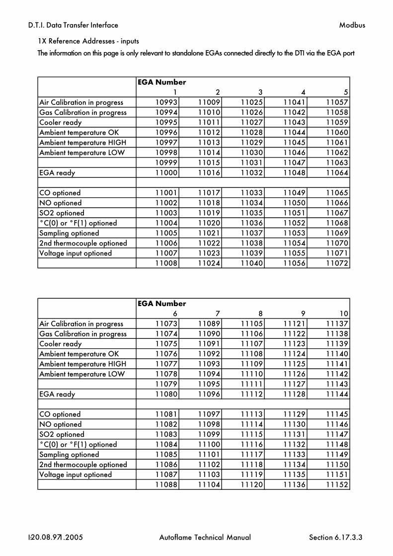
D.T.I. Data Transfer Interface
Issue: 1.11.2005 Autoflame Technical Manual Section 6.17.3.3
1X Reference Addresses - inputs
20.08.97
Modbus
The information on this page is only relevant to standalone EGAs connected directly to the DTI via the EGA port
EGA Number1 2 3 4 5
Air Calibration in progress 10993 11009 11025 11041 11057Gas Calibration in progress 10994 11010 11026 11042 11058Cooler ready 10995 11011 11027 11043 11059Ambient temperature OK 10996 11012 11028 11044 11060Ambient temperature HIGH 10997 11013 11029 11045 11061Ambient temperature LOW 10998 11014 11030 11046 11062
10999 11015 11031 11047 11063EGA ready 11000 11016 11032 11048 11064
CO optioned 11001 11017 11033 11049 11065NO optioned 11002 11018 11034 11050 11066SO2 optioned 11003 11019 11035 11051 11067°C(0) or °F(1) optioned 11004 11020 11036 11052 11068Sampling optioned 11005 11021 11037 11053 110692nd thermocouple optioned 11006 11022 11038 11054 11070Voltage input optioned 11007 11023 11039 11055 11071
11008 11024 11040 11056 11072
EGA Number6 7 8 9 10
Air Calibration in progress 11073 11089 11105 11121 11137Gas Calibration in progress 11074 11090 11106 11122 11138Cooler ready 11075 11091 11107 11123 11139Ambient temperature OK 11076 11092 11108 11124 11140Ambient temperature HIGH 11077 11093 11109 11125 11141Ambient temperature LOW 11078 11094 11110 11126 11142
11079 11095 11111 11127 11143EGA ready 11080 11096 11112 11128 11144
CO optioned 11081 11097 11113 11129 11145NO optioned 11082 11098 11114 11130 11146SO2 optioned 11083 11099 11115 11131 11147°C(0) or °F(1) optioned 11084 11100 11116 11132 11148Sampling optioned 11085 11101 11117 11133 111492nd thermocouple optioned 11086 11102 11118 11134 11150Voltage input optioned 11087 11103 11119 11135 11151
11088 11104 11120 11136 11152

D.T.I. Data Transfer Interface
Issue: 1.11.2005 Autoflame Technical Manual Section 6.17.3.4
1X Reference Addresses - On line/Off line Status
In all cases, off line is indicated by 0, on line by 1.
Modbus
MM No. Reference Address EGA No. Reference Address1 11793 1 118092 11794 2 118103 11795 3 118114 11796 4 118125 11797 5 118136 11798 6 118147 11799 7 118158 11800 8 118169 11801 9 11817
10 11802 10 11818
Digital I/O No. Reference Address Analogue I/O No. Reference Address1 11825 1 118412 11826 2 118423 11827 3 118434 11828 4 118445 11829 5 118456 11830 6 118467 11831 7 118478 11832 8 118489 11833 9 11849
10 11834 10 11850

D.T.I. Data Transfer Interface
Issue: 1.11.2005 Autoflame Technical Manual Section 6.17.3.5
1X Reference Addresses- Water Level
Modbus
MM Number1 2 3 4 5
Water level optioned- no(0)/yes(1) 12001 12201 12401 12601 12801Units- imperial(0)/metric(1) 12002 12202 12402 12602 12802Feed water pump- off(0)/on(1) 12003 12203 12403 12603 12803First out 1- normal(0)/fail(1) 12009 12209 12409 12609 12809First out 2- normal(0)/fail(1) 12010 12210 12410 12610 12810First out 3- normal(0)/fail(1) 12011 12211 12411 12611 12811First out 4- normal(0)/fail(1) 12012 12212 12412 12612 12812First out 5- normal(0)/fail(1) 12013 12213 12413 12613 12813First out 6- normal(0)/fail(1) 12014 12214 12414 12614 12814First out 7- normal(0)/fail(1) 12015 12215 12415 12615 12815First out 8- normal(0)/fail(1) 12016 12216 12416 12616 12816First out 9- normal(0)/fail(1) 12017 12217 12417 12617 12817First out 10- normal(0)/fail(1) 12018 12218 12418 12618 12818First out 11- normal(0)/fail(1) 12019 12219 12419 12619 12819First out 12- normal(0)/fail(1) 12020 12220 12420 12620 12820First out 13- normal(0)/fail(1) 12021 12221 12421 12621 12821First out 14- normal(0)/fail(1) 12022 12222 12422 12622 12822First out 15- normal(0)/fail(1) 12023 12223 12423 12623 12823
MM Number6 7 8 9 10
Water level optioned- no(0)/yes(1) 13001 13201 13401 13601 13801Units- imperial(0)/metric(1) 13002 13202 13402 13602 13802Feed water pump- off(0)/on(1) 13003 13203 13403 13603 13803First out 1- normal(0)/fail(1) 13009 13209 13409 13609 13809First out 2- normal(0)/fail(1) 13010 13210 13410 13610 13810First out 3- normal(0)/fail(1) 13011 13211 13411 13611 13811First out 4- normal(0)/fail(1) 13012 13212 13412 13612 13812First out 5- normal(0)/fail(1) 13013 13213 13413 13613 13813First out 6- normal(0)/fail(1) 13014 13214 13414 13614 13814First out 7- normal(0)/fail(1) 13015 13215 13415 13615 13815First out 8- normal(0)/fail(1) 13016 13216 13416 13616 13816First out 9- normal(0)/fail(1) 13017 13217 13417 13617 13817First out 10- normal(0)/fail(1) 13018 13218 13418 13618 13818First out 11- normal(0)/fail(1) 13019 13219 13419 13619 13819First out 12- normal(0)/fail(1) 13020 13220 13420 13620 13820First out 13- normal(0)/fail(1) 13021 13221 13421 13621 13821First out 14- normal(0)/fail(1) 13022 13222 13422 13622 13822First out 15- normal(0)/fail(1) 13023 13223 13423 13623 13823

D.T.I. Data Transfer Interface
Issue: 1.11.2005 Autoflame Technical Manual Section 6.17.4.1
6.17.4 3X Reference Addresses - Input Registers
Analog Inputs
Software Version
30097 Software Version Number30098 Software Issue Number
Modbus
Analogue Input NumberI/O Module Number
1 2 3 4 5 61 30017 30018 30019 30020 30021 300222 30025 30026 30027 30028 30029 300303 30033 30034 30035 30036 30037 300384 30041 30042 30043 30044 30045 300465 30049 30050 30051 30052 30053 300546 30057 30058 30059 30060 30061 300627 30065 30066 30067 30068 30069 300708 30073 30074 30075 30076 30077 300789 30081 30082 30083 30084 30085 30086
10 30089 30090 30091 30092 30093 30094

D.T.I. Data Transfer Interface
Issue: 1.11.2005 Autoflame Technical Manual Section 6.17.4.2
3X Reference Addresses - Input Registers
Modbus
MM Number1 2 3 4 5
Load index 30101 30151 30201 30251 30301Startup/firing status 30102 30152 30202 30252 30302Sequence status 30103 30153 30203 30253 30303Burner rating 30104 30154 30204 30254 30304Actual value 30105 30155 30205 30255 30305Required value 30106 30156 30206 30256 30306Fuel selected 30107 30157 30207 30257 30307Number of channels 30108 30158 30208 30258 30308Channel 1 position 30109 30159 30209 30259 30309Channel 2 position 30110 30160 30210 30260 30310Channel 3 position 30111 30161 30211 30261 30311Channel 4 position 30112 30162 30212 30262 30312MM error number 30113 30163 30213 30263 30313Single/twin operation 30114 30164 30214 30264 30314Run O2 30115 30165 30215 30265 30315Run CO2 30116 30166 30216 30266 30316Run CO 30117 30167 30217 30267 30317Run exhaust temperature 30118 30168 30218 30268 30318Run efficiency 30119 30169 30219 30269 30319Run NO 30120 30170 30220 30270 30320Run SO2 30121 30171 30221 30271 30321Comm. O2 30122 30172 30222 30272 30322Comm. CO2 30123 30173 30223 30273 30323Comm. CO 30124 30174 30224 30274 30324Comm. Exhaust temperature 30125 30175 30225 30275 30325Comm. Efficiency 30126 30176 30226 30276 30326Comm. NO 30127 30177 30227 30277 30327Comm. SO2 30128 30178 30228 30278 30328EGA error number 30129 30179 30229 30279 30329Minimum required value 30130 30180 30230 30280 30330Maximum required value 30131 30181 30231 30281 30331Present flow units 30132 30182 30232 30282 30332Present flow thousands 30133 30183 30233 30283 30333Fuel 1 flow total units 30134 30184 30234 30284 30334Fuel 1 flow total thousands 30135 30185 30235 30285 30335Fuel 1 flow total millions 30136 30186 30236 30286 30336Fuel 2 flow total units 30137 30187 30237 30287 30337Fuel 2 flow total thousands 30138 30188 30238 30288 30338Fuel 2 flow total millions 30139 30189 30239 30289 30339Fuel 3 flow total units 30140 30190 30240 30290 30340Fuel 3 flow total thousands 30141 30191 30241 30291 30341Fuel 3 flow total millions 30142 30192 30242 30292 30342Run ambient 30143 30193 30243 30293 30343Run delta T 30144 30194 30244 30294 30344COM ambient 30145 30195 30245 30295 30345COM delta T 30146 30196 30246 30296 30346Mk6/Mini6/Mini5 (0,4,5) 30147 30197 30247 30297 30347

D.T.I. Data Transfer Interface
Issue: 1.11.2005 Autoflame Technical Manual Section 6.17.4.3
3X Reference Addresses - Input Registers
Modbus
MM Number6 7 8 9 10
Load index 30351 30401 30451 30501 30551Startup/firing status 30352 30402 30452 30502 30552Sequence status 30353 30403 30453 30503 30553Boiler capacity 30354 30404 30454 30504 30554Actual value 30355 30405 30455 30505 30555Required value 30356 30406 30456 30506 30556Fuel selected 30357 30407 30457 30507 30557Number of channels 30358 30408 30458 30508 30558Channel 1 position 30359 30409 30459 30509 30559Channel 2 position 30360 30410 30460 30510 30560Channel 3 position 30361 30411 30461 30511 30561Channel 4 position 30362 30412 30462 30512 30562MM error number 30363 30413 30463 30513 30563Single/twin operation 30364 30414 30464 30514 30564Run O2 30365 30415 30465 30515 30565Run CO2 30366 30416 30466 30516 30566Run CO 30367 30417 30467 30517 30567Run exhaust temperature 30368 30418 30468 30518 30568Run efficiency 30369 30419 30469 30519 30569Run NO 30370 30420 30470 30520 30570Run SO2 30371 30421 30471 30521 30571Comm. O2 30372 30422 30472 30522 30572Comm. CO2 30373 30423 30473 30523 30573Comm. CO 30374 30424 30474 30524 30574Comm. Exhaust temperature 30375 30425 30475 30525 30575Comm. Efficiency 30376 30426 30476 30526 30576Comm. NO 30377 30427 30477 30527 30577Comm. SO2 30378 30428 30478 30528 30578EGA error number 30379 30429 30479 30529 30579Minimum required value 30380 30430 30480 30530 30580Maximum required value 30381 30431 30481 30531 30581Present flow units 30382 30432 30482 30532 30582Present flow thousands 30383 30433 30483 30533 30583Fuel 1 flow total units 30384 30434 30484 30534 30584Fuel 1 flow total thousands 30385 30435 30485 30535 30585Fuel 1 flow total millions 30386 30436 30486 30536 30586Fuel 2 flow total units 30387 30437 30487 30537 30587Fuel 2 flow total thousands 30388 30438 30488 30538 30588Fuel 2 flow total millions 30389 30439 30489 30539 30589Fuel 3 flow total units 30390 30440 30490 30540 30590Fuel 3 flow total thousands 30391 30441 30491 30541 30591Fuel 3 flow total millions 30392 30442 30492 30542 30592Run ambient 30393 30443 30493 30543 30593Run delta T 30394 30444 30494 30544 30594COM ambient 30395 30445 30495 30545 30595COM delta T 30396 30446 30496 30546 30596Mk6/Mini6/Mini5 (0,4,5) 30397 30447 30497 30547 30597
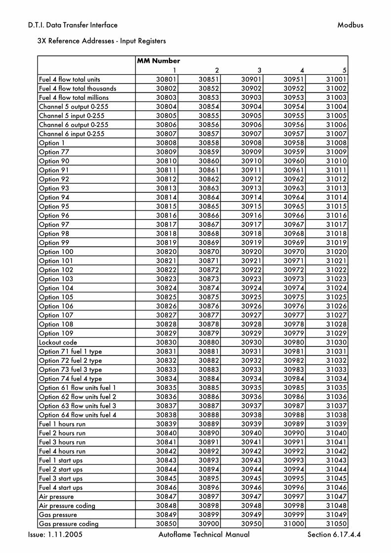
D.T.I. Data Transfer Interface
Issue: 1.11.2005 Autoflame Technical Manual Section 6.17.4.4
Modbus
MM Number1 2 3 4 5
Fuel 4 flow total units 30801 30851 30901 30951 31001Fuel 4 flow total thousands 30802 30852 30902 30952 31002Fuel 4 flow total millions 30803 30853 30903 30953 31003Channel 5 output 0-255 30804 30854 30904 30954 31004Channel 5 input 0-255 30805 30855 30905 30955 31005Channel 6 output 0-255 30806 30856 30906 30956 31006Channel 6 input 0-255 30807 30857 30907 30957 31007Option 1 30808 30858 30908 30958 31008Option 77 30809 30859 30909 30959 31009Option 90 30810 30860 30910 30960 31010Option 91 30811 30861 30911 30961 31011Option 92 30812 30862 30912 30962 31012Option 93 30813 30863 30913 30963 31013Option 94 30814 30864 30914 30964 31014Option 95 30815 30865 30915 30965 31015Option 96 30816 30866 30916 30966 31016Option 97 30817 30867 30917 30967 31017Option 98 30818 30868 30918 30968 31018Option 99 30819 30869 30919 30969 31019Option 100 30820 30870 30920 30970 31020Option 101 30821 30871 30921 30971 31021Option 102 30822 30872 30922 30972 31022Option 103 30823 30873 30923 30973 31023Option 104 30824 30874 30924 30974 31024Option 105 30825 30875 30925 30975 31025Option 106 30826 30876 30926 30976 31026Option 107 30827 30877 30927 30977 31027Option 108 30828 30878 30928 30978 31028Option 109 30829 30879 30929 30979 31029Lockout code 30830 30880 30930 30980 31030Option 71 fuel 1 type 30831 30881 30931 30981 31031Option 72 fuel 2 type 30832 30882 30932 30982 31032Option 73 fuel 3 type 30833 30883 30933 30983 31033Option 74 fuel 4 type 30834 30884 30934 30984 31034Option 61 flow units fuel 1 30835 30885 30935 30985 31035Option 62 flow units fuel 2 30836 30886 30936 30986 31036Option 63 flow units fuel 3 30837 30887 30937 30987 31037Option 64 flow units fuel 4 30838 30888 30938 30988 31038Fuel 1 hours run 30839 30889 30939 30989 31039Fuel 2 hours run 30840 30890 30940 30990 31040Fuel 3 hours run 30841 30891 30941 30991 31041Fuel 4 hours run 30842 30892 30942 30992 31042Fuel 1 start ups 30843 30893 30943 30993 31043Fuel 2 start ups 30844 30894 30944 30994 31044Fuel 3 start ups 30845 30895 30945 30995 31045Fuel 4 start ups 30846 30896 30946 30996 31046Air pressure 30847 30897 30947 30997 31047Air pressure coding 30848 30898 30948 30998 31048Gas pressure 30849 30899 30949 30999 31049Gas pressure coding 30850 30900 30950 31000 31050
3X Reference Addresses - Input Registers

D.T.I. Data Transfer Interface
Issue: 1.11.2005 Autoflame Technical Manual Section 6.17.4.5
Modbus
MM Number6 7 8 9 10
Fuel 4 flow total units 31051 31101 31151 31201 31251Fuel 4 flow total thousands 31052 31102 31152 31202 31252Fuel 4 flow total millions 31053 31103 31153 31203 31253Channel 5 output 0-255 31054 31104 31154 31204 31254Channel 5 input 0-255 31055 31105 31155 31205 31255Channel 6 output 0-255 31056 31106 31156 31206 31256Channel 6 input 0-255 31057 31107 31157 31207 31257Option 1 31058 31108 31158 31208 31258Option 77 31059 31109 31159 31209 31259Option 90 31060 31110 31160 31210 31260Option 91 31061 31111 31161 31211 31261Option 92 31062 31112 31162 31212 31262Option 93 31063 31113 31163 31213 31263Option 94 31064 31114 31164 31214 31264Option 95 31065 31115 31165 31215 31265Option 96 31066 31116 31166 31216 31266Option 97 31067 31117 31167 31217 31267Option 98 31068 31118 31168 31218 31268Option 99 31069 31119 31169 31219 31269Option 100 31070 31120 31170 31220 31270Option 101 31071 31121 31171 31221 31271Option 102 31072 31122 31172 31222 31272Option 103 31073 31123 31173 31223 31273Option 104 31074 31124 31174 31224 31274Option 105 31075 31125 31175 31225 31275Option 106 31076 31126 31176 31226 31276Option 107 31077 31127 31177 31227 31277Option 108 31078 31128 31178 31228 31278Option 109 31079 31129 31179 31229 31279Lockout code 31080 31130 31180 31230 31280Option 71 fuel 1 type 31081 31131 31181 31231 31281Option 72 fuel 2 type 31082 31132 31182 31232 31282Option 73 fuel 3 type 31083 31133 31183 31233 31283Option 74 fuel 4 type 31084 31134 31184 31234 31284Option 61 flow units fuel 1 31085 31135 31185 31235 31285Option 62 flow units fuel 2 31086 31136 31186 31236 31286Option 63 flow units fuel 3 31087 31137 31187 31237 31287Option 64 flow units fuel 4 31088 31138 31188 31238 31288Fuel 1 hours run 31089 31139 31189 31239 31289Fuel 2 hours run 31090 31140 31190 31240 31290Fuel 3 hours run 31091 31141 31191 31241 31291Fuel 4 hours run 31092 31142 31192 31242 31292Fuel 1 start ups 31093 31143 31193 31243 31293Fuel 2 start ups 31094 31144 31194 31244 31294Fuel 3 start ups 31095 31145 31195 31245 31295Fuel 4 start ups 31096 31146 31196 31246 31296Air pressure 31097 31147 31197 31247 31297Air pressure coding 31098 31148 31198 31248 31298Gas pressure 31099 31149 31199 31249 31299Gas pressure coding 31100 31150 31200 31250 31300
3X Reference Addresses - Input Registers

D.T.I. Data Transfer Interface
Issue: 1.11.2005 Autoflame Technical Manual Section 6.17.4.6
3X Reference Addresses - Input Registers
The information on this page is only relevant to standalone EGAs connected directly to the DTI via the EGA port.
Modbus
EGA Number1 2 3 4 5
Fuel selected 30601 30621 30641 30661 30681% O2 30602 30622 30642 30662 30682% CO2 30603 30623 30643 30663 30683ppm CO 30604 30624 30644 30664 30684ppm NO 30605 30625 30645 30665 30685ppm SO2 30606 30626 30646 30666 30686Exhaust temperature 30607 30627 30647 30667 30687Efficiency 30608 30628 30648 30668 30688Error number 30609 30629 30649 30669 30689% voltage input 30610 30630 30650 30670 30690Exhaust ? T 30611 30631 30651 30671 30691Ambient 30612 30632 30652 30672 30692Auxiliary temperature 30613 30633 30653 30673 30693Service L.E.D.'s 30614 30634 30654 30674 30694
EGA Number6 7 8 9 10
Fuel selected 30701 30721 30741 30761 30781% O2 30702 30722 30742 30762 30782% CO2 30703 30723 30743 30763 30783ppm CO 30704 30724 30744 30764 30784ppm NO 30705 30725 30745 30765 30785ppm SO2 30706 30726 30746 30766 30786Exhaust temperature 30707 30727 30747 30767 30787Efficiency 30708 30728 30748 30768 30788Error number 30709 30729 30749 30769 30789% voltage input 30710 30730 30750 30770 30790Exhaust ? T 30711 30731 30751 30771 30791Ambient 30712 30732 30752 30772 30792Auxiliary temperature 30713 30733 30753 30773 30793Service L.E.D.'s 30714 30734 30754 30774 30794

D.T.I. Data Transfer Interface
Issue: 1.11.2005 Autoflame Technical Manual Section 6.17.4.7
Modbus
MM Number1 Error 313012 Error 313023 Error 313034 Error 313045 Error 313056 Error 313067 Error 313078 Error 313089 Error 31309
10 Error 31310
MM Number1 Lockout 313112 Lockout 313123 Lockout 313134 Lockout 313145 Lockout 313156 Lockout 313167 Lockout 313178 Lockout 313189 Lockout 31319
10 Lockout 31320
3X Reference Addresses - Input Registers
Please see section 6.17.8.4 for a list of the error codes that can be seen for each Modbusaddress.
Please see section 6.17.8.5 for a list of the lockout codes that can be seen for each Modbusaddress.

D.T.I. Data Transfer Interface
Issue: 1.11.2005 Autoflame Technical Manual Section 6.17.4.8
Modbus
Analogue Channel NumberI/O Module Number 1 2 3 4 5 6
1 byte 7/6 31324 31328 31332 31336 31340 31344byte 5/4 31323 31327 31331 31335 31339 31343byte 3/2 31322 31326 31330 31334 31338 31342byte 1/0 31321 31325 31329 31333 31337 31341
2 byte 7/6 31348 31352 31356 31360 31364 31368byte 5/4 31347 31351 31355 31359 31363 31367byte 3/2 31346 31350 31354 31358 31362 31366byte 1/0 31345 31349 31353 31357 31361 31365
3 byte 7/6 31372 31376 31380 31384 31388 31392byte 5/4 31371 31375 31379 31383 31387 31391byte 3/2 31370 31374 31378 31382 31386 31390byte 1/0 31369 31373 31377 31381 31385 31389
4 byte 7/6 31396 31400 31404 31408 31412 31416byte 5/4 31395 31399 31403 31407 31411 31415byte 3/2 31394 31398 31402 31406 31410 31414byte 1/0 31393 31397 31401 31405 31409 31413
5 byte 7/6 31420 31424 31428 31432 31436 31440byte 5/4 31419 31423 31427 31431 31435 31439byte 3/2 31418 31422 31426 31430 31434 31438byte 1/0 31417 31421 31425 31429 31433 31437
6 byte 7/6 31444 31448 31452 31456 31460 31464byte 5/4 31443 31447 31451 31455 31459 31463byte 3/2 31442 31446 31450 31454 31458 31462byte 1/0 31441 31445 31449 31453 31457 31461
7 byte 7/6 31468 31472 31476 31480 31484 31488byte 5/4 31467 31471 31475 31479 31483 31487byte 3/2 31466 31470 31474 31478 31482 31486byte 1/0 31465 31469 31473 31477 31481 31485
8 byte 7/6 31492 31496 31500 31504 31508 31512byte 5/4 31491 31495 31499 31503 31507 31511byte 3/2 31490 31494 31498 31502 31506 31510byte 1/0 31489 31493 31497 31501 31505 31509
9 byte 7/6 31516 31520 31524 31528 31532 31536byte 5/4 31515 31519 31523 31527 31531 31535byte 3/2 31514 31518 31522 31526 31530 31534byte 1/0 31513 31517 31521 31525 31529 31533
10 byte 7/6 31540 31544 31548 31552 31556 31560byte 5/4 31539 31543 31547 31551 31555 31559byte 3/2 31538 31542 31546 31550 31554 31558byte 1/0 31537 31541 31545 31549 31553 31557
3X Reference Addresses - Analogue inputs- totalised values

D.T.I. Data Transfer Interface
Issue: 1.11.2005 Autoflame Technical Manual Section
3X Reference Addresses - Water Level Input Registers
MM Number1 2 3 4 5
Probe 1 signal 32001 32101 32201 32301 32401Probe 1 reference 32002 32102 32202 32302 32402
32003 32103 32203 32303 32403Probe 1 Version/Issue (ms/ls byte) 32004 32104 32204 32304 32404Probe 2 signal 32005 32105 32205 32305 32405Probe 2 reference 32006 32106 32206 32306 32406
32007 32107 32207 32307 32407Probe 2 Version/Issue (ms/ls byte) 32008 32108 32208 32308 32408Alarm status 32009 32109 32209 32309 32409Level status 32010 32110 32210 32310 32410WL version/Issue (ms/ls byte) 32011 32111 32211 32311 32411Alarm code 32012 32112 32212 32312 32412
32013 32113 32213 32313 32413Steam temperature °C 32014 32114 32214 32314 32414Feed water temperature °C 32015 32115 32215 32315 32415Steam rate lb/hr 32016 32116 32216 32316 32416Heat to steam Btus/lb 32017 32117 32217 32317 32417Control element % 32018 32118 32218 32318 32418
32019 32119 32219 32319 32419Control point raised 32020 32120 32220 32320 32420
32021 32121 32221 32321 3242132022 32122 32222 32322 32422
Totalised steam lbs (ls word) 32023 32123 32223 32323 32423Totalised steam lbs (ms word) 32024 32124 32224 32324 32424Steam temperature F 32025 32125 32225 32325 32425Feed water temperature F 32026 32126 32226 32326 32426Steam rate Kgs/hr 32027 32127 32227 32327 32427Heat to steam KJ/Kg 32028 32128 32228 32328 32428Totalised steam Kgs (ls word) 32029 32129 32229 32329 32429Totalised Steam Kgs (ms word) 32030 32130 32230 32330 32430Probe 1 temperature °C 32031 32131 32231 32331 32431Probe 2 temperature °C 32032 32132 32232 32332 32432Probe 1 temperature °F 32033 32133 32233 32333 32433Probe 2 temperature °F 32034 32134 32234 32334 32434
6.17.4.9
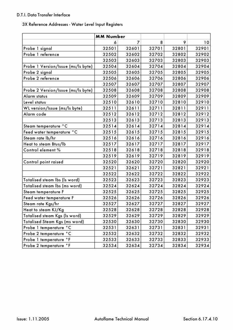
D.T.I. Data Transfer Interface
Issue: 1.11.2005 Autoflame Technical Manual Section
3X Reference Addresses - Water Level Input Registers
6.17.4.10
MM Number6 7 8 9 10
Probe 1 signal 32501 32601 32701 32801 32901Probe 1 reference 32502 32602 32702 32802 32902
32503 32603 32703 32803 32903Probe 1 Version/Issue (ms/ls byte) 32504 32604 32704 32804 32904Probe 2 signal 32505 32605 32705 32805 32905Probe 2 reference 32506 32606 32706 32806 32906
32507 32607 32707 32807 32907Probe 2 Version/Issue (ms/ls byte) 32508 32608 32708 32808 32908Alarm status 32509 32609 32709 32809 32909Level status 32510 32610 32710 32810 32910WL version/Issue (ms/ls byte) 32511 32611 32711 32811 32911Alarm code 32512 32612 32712 32812 32912
32513 32613 32713 32813 32913Steam temperature °C 32514 32614 32714 32814 32914Feed water temperature °C 32515 32615 32715 32815 32915Steam rate lb/hr 32516 32616 32716 32816 32916Heat to steam Btus/lb 32517 32617 32717 32817 32917Control element % 32518 32618 32718 32818 32918
32519 32619 32719 32819 32919Control point raised 32520 32620 32720 32820 32920
32521 32621 32721 32821 3292132522 32622 32722 32822 32922
Totalised steam lbs (ls word) 32523 32623 32723 32823 32923Totalised steam lbs (ms word) 32524 32624 32724 32824 32924Steam temperature F 32525 32625 32725 32825 32925Feed water temperature F 32526 32626 32726 32826 32926Steam rate Kgs/hr 32527 32627 32727 32827 32927Heat to steam KJ/Kg 32528 32628 32728 32828 32928Totalised steam Kgs (ls word) 32529 32629 32729 32829 32929Totalised Steam Kgs (ms word) 32530 32630 32730 32830 32930Probe 1 temperature °C 32531 32631 32731 32831 32931Probe 2 temperature °C 32532 32632 32732 32832 32932Probe 1 temperature °F 32533 32633 32733 32833 32933Probe 2 temperature °F 32534 32634 32734 32834 32934

D.T.I. Data Transfer Interface
Issue: 1.11.2005 Autoflame Technical Manual Section 6.17.5.1
6.17.5 4X Reference Addresses - Holding Registers
Individual Required value for each Micro Modulation unit
Global Required Value for all MMs40011
Lead Boiler selection40012
Reserved - DO NOT USE40013 - 40016
Modbus
MM ID number Reference Address1 400012 400023 400034 400045 400056 400067 400078 400089 40009
10 40010

D.T.I. Data Transfer Interface
Issue: 1.11.2005 Autoflame Technical Manual Section 6.17.5.2
4X Reference Addresses - Holding Registers
Modbus
Analogue Output NumberI/O Module Number
1 2 3 4 5 61 40017 40018 40019 40020 40021 400222 40025 40026 40027 40028 40029 400303 40033 40034 40035 40036 40037 400384 40041 40042 40043 40044 40045 400465 40049 40050 40051 40052 40053 400546 40057 40058 40059 40060 40061 400627 40065 40066 40067 40068 40069 400708 40073 40074 40075 40076 40077 400789 40081 40082 40083 40084 40085 40086
10 40089 40090 40091 40092 40093 40094

D.T.I. Data Transfer Interface
Issue: 1.11.2005 Autoflame Technical Manual Section 6.17.6
Switch Bank 1
Set the Modbus address accordingly.
For example, to set address number 123:
100s = 110s = 21s = 3
6.17.6 Switch Settings - Modbus Operation
Modbus
Switch Bank 2
1 off - Modbus 'ASCII' modeon - Modbus 'RTU' mode
2 Transmission settingsoff - 8 data bits, 1 stop bit, no parity.on - 8 data bits, 1 stop bit, even parity.
3-5 no user function, must be set off
6 Windows PCDTI/MODBUS operationoff - 422 port set for Windows PCDTIon - 422 port set for MODBUS
7 Windows PCDTI/MODBUS operationoff - PC port set for WinPCDTIon - PC port set for MODBUS
8 MM Port Baud Rateoff - 9600 (Mk6, Mini Mk6 and Mini Mk5 MMs)on - 4800 (Older Mk5 and Mini MMs)** Technical Memo: Data Communication Compatibility 3/9/1999
ON
OFF1 2 3 4 5 6 7 8
10s100s 1s
Switch Bank 1 Switch Bank 2

D.T.I. Data Transfer Interface
Issue: 1.11.2005 Autoflame Technical Manual Section 6.17.7
6.17.7 Other Information
Modbus Transmission Interface
There is no hardware or software flow control on any port.
Baud Rate 9600.
Supported MODBUS Commands
1 Read coil status2 Read input status3 Read holding registers4 Read input registers5 Force single coil6 Preset single register15 Force multiple coils16 Preset multiple registers
6.17.7.3 Supported Exception Responses
Exception responses are not supported. No response is given to an unrecognised request.
6.17.7.4 Serial Port Connections
RS232 'PC' port - 9 Way Female D connector
PIN Function
2 Data out 3 Data in 5 Signal ground
RS422 port - Screw terminal blocks
Receive and transmit connections are as identified on printed circuit board.
Modbus

D.T.I. Data Transfer Interface
Issue: 1.11.2005 Autoflame Technical Manual Section
6.17.8 Relevance of MM/EGA data
Each MM/EGA can provide the following information. All values are instantaneous. Each MM/EGA system updates the DTI approximately once every 20 seconds. Certain values and somevalues under certain conditions may require a decimal point. In these cases the user must add thedecimal point accordingly (* only valid if EGA operational on system)
Digital Inputs (1x references)
Command status of M.M. ‘CR Relay’ O - Off,1 - On
Flow detector type O - Temperature,1 - Pressure
Optioned for flow metering O - No,1 - Yes
CO off/on on fuel 2 (fuel 1 CO always on)O - Off, 1 - OnTemperature units O - C,
1 - FPressure units O - bar,
1 - psiOptioned for voltage input modulation O - No,
1 - YesOptioned for EGA O - No,
1 - YesBoiler up to ‘trimming’ temperature O - No,
1 - YesEGA cooler temperature ready O - No,
1 - YesEGA ambient temperature OK O - No,
1 - YesOptioned to display NO O - No,
1 - YesOption to display SO O - No,
1 - YesEGA ambient temperature low/high(relevant if bit 3 (ambient temperature) is O) O - LOW,
1 - HIGHOptioned for sequencing O - NO,
1 - YESSetpoint/Disable commands accepted O - NO,
1 - YESHand operation status O - Modulating,
1 - Hand OperationLow flame hold status O - Modulating
1 - Low Flame HoldThis MM controlling DTI bus communication O - NO,
1 - YESInput 41 set (lead boiler select) O - NO,
1 - YES
6.17.8
Modbus

D.T.I. Data Transfer Interface
Issue: 1.11.2005 Autoflame Technical Manual Section
Lead boiler status O - not lead boiler1 - lead boiler
‘Disabled’ status O - enabled1 - disabled
Slave burner indication status - test bit O O - master plus one,1 - master minus one
Analogue Inputs (3x references)
0-100 Firing rate/load index - percentage19-26 Indicates burner firing status
19 waiting for stat circuit to complete20 waiting for command to drive air damper to purge position21 driving air damper to purge position22 purging, waiting for command to drive valves to ignition position23 driving valves to ignition position24 ignition taking place25 burner firing and modulating26 post purge taking place(if O indicated transmission is direct from EGA)
0-3 Sequencing command status for this boilerSequence state0 - ON1 - STANDBY2 - WARM3 - OFF
0-250 Maximum firing rate - just the number entered in option 340-999 Actual value of boiler flow temperature - degrees C0.0-99.9 (Pressure Bar)0-999 Desired value of boiler flow temperature - degrees C0.0-99.9 (Pressure Bar)0-2 Present fuel selected 0 - Fuel 1 (usually GAS)
1 - Fuel 2 (usually OIL)2 - Fuel 3 (usually OIL)
1-7 Number of Channels in operation (add one to this to get total number)-6.0-96.0 CH1 positioning motor position degrees angular-6.0-96.0 CH2 positioning motor position degrees angular-6.0-96.0 CH3 positioning motor position degrees angular-6.0-96.0 Ch4 positioning motor position degrees angular0-N Fatal Error Code 0 - System is OK
1 - N system shut downValue is as MM ERR display
0-2 Single/twin burner operation0 - single burner1 - twin burner (both together only)2 - twin burner (both together/one or the other)
0-25.5 Present value percentage oxygen in flue gas0-25.5 Present value percentage carbon dioxide in flue gas0-999 Present value ppm carbon monoxide in flue gas0-999 Present value flue gas temperature0-99.9 Present value percentage combustion efficiency
6.17.8.1
Modbus

D.T.I. Data Transfer Interface
Issue: 1.11.2005 Autoflame Technical Manual Section
0-999 Actual value NO0-999 Actual value SO20-25.5 Commissioned value percentage oxygen in flue gas0-25.5 Commissioned value percentage carbon dioxide in flue gas0-999 Commissioned value ppm carbon monoxide in flue gas0-999 Commissioned value flue gas temperature0-99.9 Commissioned value percentage combustion efficiency0-999 Commission value NO0-999 Commission value SO20-N EGA error code normal - 0 any other value is error0-99.9 Minimum setpoint accepted(0-999, 0-99.9)0-99.9 Minimum setpoint accepted(0-999, 0-99.9)0-999 Flow value units0-999 Flow value thousands
(multiply thousands value by 1000 then add units value then divide by 100 to getflow value)0-999 Fuel 1 totalised value units0-999 Fuel 1 totalised value thousands0-999 Fuel 1 totalised value millions0-999 Fuel 2 totalised value units0-999 Fuel 2 totalised value thousands0-999 Fuel 2 totalised value millions0-999 Fuel 3 totalised value units0-999 Fuel 3 totalised value thousands0-999 Fuel 3 totalised value millions-6.0-96.0 Ch5 positioning motor position degrees angular-6.0-96.0 Ch6 positioning motor position degrees angular-6.0-96.0 Ch7 positioning motor position degrees angular-6.0-96.0 Ch8 positioning motor position degrees angular
6.17.8.2
Modbus

D.T.I. Data Transfer Interface
Issue: 1.11.2005 Autoflame Technical Manual Section
Code Explanation19 Waiting for stat circuit to complete20 Waiting for command to drive air damper to purge position21 Driving air damper to purge position22 Purging: Waiting for command o drive valves to ignition position23 Driving valves to ignition position24 Ignition taking place25 Burner firing and modulating26 Post purge taking place
The following table lists the startup/firing status codes along with an explanation of what the codesmean. This is for Modbus addresses:
30102 MM ID #130152 MM ID #230202 MM ID #330252 MM ID #430302 MM ID #530352 MM ID #630402 MM ID #730452 MM ID #830502 MM ID #930552 MM ID #10
6.17.8.3

D.T.I. Data Transfer Interface
Issue: 1.11.2005 Autoflame Technical Manual Section
Code Error Message/Explanation1 CH1 positioning error2 CH2 positioning error3 load detector4 Software error5 PROM memory fault6 Commisssion data fault7 RAM memory fault8 CH3 positioning error9 CH4 positioning error
40 CR1 test failure41 CH1 gain error42 CH2 gain error43 CH3 gain error44 5 volt supply error45 Watchdog- CR2 safety test failed46 CH4 gain error47 A/D converter80 CH5 error81 CH6 error83 CH5 feedback signal error84 CH6 feedbcak signal error92 Air pressure outside limits
100 Twin burner communications failed
The following table lists the error codes along with an explanation of what the codes mean. This is forModbus addresses:
31301 MM ID #131302 MM ID #231303 MM ID #331304 MM ID #431305 MM ID #531306 MM ID #631307 MM ID #731308 MM ID #831309 MM ID #931310 MM ID #10
6.17.8.4

D.T.I. Data Transfer Interface
Issue: 1.11.2005 Autoflame Technical Manual Section
The following table lists the lockout codes along with an explanation of what the codes mean. This isfor Modbus addresses:
31311 MM ID #131312 MM ID #231313 MM ID #331314 MM ID #431315 MM ID #531316 MM ID #631317 MM ID #731318 MM ID #831319 MM ID #931320 MM ID #10
6.17.8.5
Code Lockout Message Code Lockout Message1 CPI wrong state 27 Watchdog fail 2c2 No air proving 28 Watchdog fail 2d3 Ignition output fault 29 Input faulty4 Motor output fault 30 Gas sensor error5 Start gas output fault 31 Air sensor error6 Main gas output 1 fault 32 Low gas pressure7 Main gas output 2 fault 33 VPS air zeroing fail8 Vent valve output fault 34 VPS gas pressure low9 Fail safe relay fault 35 UV short circuit
10 Simulated flame 36 Oil pressure too low11 VPS air proving fail 37 Oil pressure too high12 VPS gas proving fail 38 CPU test failed13 No flame signal 39 Freeze timeout14 Shutter fault 40 Purge air pressure low15 No cpi reset 41 Option 141 incorrect16 Lockout permanently active 42 Terminal 86 inverse17 Gas pressure too low 43 Terminal 85-86 fault18 Gas pressure too high 44 Prove cct fail19 RAM test failed 45 No prove cct set20 PROM test failed 46 No prove cct reset21 Watchdog fault 1a 198 BC input short22 Watchdog fault 1b 199 Lockout 19923 Watchdog fault 1c 20024 Watchdog fault 1d 201 Lockout 20125 Watchdog fail 2a 202 EEPROM faulty26 Watchdog fail 2b

D.T.I. Data Transfer Interface
Issue: 1.11.2005 Autoflame Technical Manual Section
Modbus
6.17.9 Further Information
For more detailed information regarding the Modbus protocol, refer to the following publication:
Modicon Modbus Protocol Reference Guide,PI-MBUS-300
Also visit the website: www.modicon.com
6.17.9

D.T.I. Data Transfer Interface
Issue: 1.11.2005 Autoflame Technical Manual Section
6.18 AUTOFLAME WINPCDTI SOFTWARE
The Autoflame WinPCDTI software runs under Windows 95/98/NT4 and brings together our currentrange of products.
There are two modes of program operation:
Plant Supervisor for local controlPlant Manager for remote monitoring via modem for a number of sites.
The software is presented in an intuitive graphical format where pictures and buttons are used to leadthe operator through all the available functions.
6.18.1
Software Installation
To install WinPCDTI to your computer, follow the instructions supplied with the diskettes.
During the installation, you will be prompted for your serial number. This is the four part code printedon one side of your dongle, e.g. DTI-1111-AAAA-1111.
The dongle must be attached to your PC for WinPCDTI to operate. The first time the program is run, theWelcome screen prompts the user to select the mode of operation, either Plant Manager or PlantSupervisor. You will need to specify which serial port you are using (COM1/COM2).
WinPCDTI Software

D.T.I. Data Transfer Interface
Issue: 1.11.2005 Autoflame Technical Manual Section
Section 6.19: Johnson Metasys Interface Index
6.19 Index
6.19.1 Overview
6.19.2 Connecting the DTI to Metasys
6.19.3 Network Point Table
6.19.3.1 First 10 addresses (MM/EGA units)6.19.3.2 Eleventh address (I/O units)

D.T.I. Data Transfer Interface
Issue: 1.11.2005 Autoflame Technical Manual Section 6.19.1
6.19.1 Overview
Autoflame's DTI unit interfaces with the Autoflame MM/EGA system. In doing so it provides a simplemeans of gathering information and presenting it to a bus or network. The DTI will interface with up toten MM/EGA systems and up to ten Analog and/or Digital units. This section details informationregarding the Data Transfer Interface (DTI) 'Metasys' interface.
6.19.1.2 Requirements
Compatible software versions are:
DTI unit (DTI20010) Serial number 095132 onwardsDTI EPROM Metasys v1.02 onwardsMM Mk5 EPROM 300/0/15/4mini Mk5 EPROM (2channel) 610/1/15/3mini Mk5 EPROM (3channel) 620/1/15/3
Metasys

D.T.I. Data Transfer Interface
Issue: 1.11.2005 Autoflame Technical Manual Section 6.19.2
6.19.2 Connecting the DTI to Metasys
The DTI has a port which provides direct access to the Metasys network. Connection is made via ascrew terminal block labelledd 'RS485+', 'RS485-' and 'RS485 screen'. Only the DTI address needs tobe set by the installation engineer. The following diagram illustrates the connections required.
Selecting the DTI address
The DTI N2 address is selected by means of Switch Bank 1. Set the three rotary switches appropriately.For example, to set address number 123: 100s = 1
10s = 21s = 3
The DTI can occupy any address on the Metasys network, however the DTI requires eleven freeconsecutive address, starting from and including the address selected using the switches. If the DTI isgiven address 30, 30 is selected on SW1. However addresses 31 to 40 must also be free on the network.
If Metasys operation is required alongside Modbus operation, the Metasys address and Modbusaddress will have to be the same.
If WinPCDTI/Modbus/Metasys combinations are used, the required value and enable/disable com-mands can be implemented by any of these three means.
Metasys
N2 +N2 -SCREEN
ON
OFF1 2 3 4 5 6 7 8
10s100s 1s
Switch Bank 1 Switch Bank 2

D.T.I. Data Transfer Interface
Issue: 1.11.2005 Autoflame Technical Manual Section 6.19.3
6.19.3 Network Point Table
The DTI occupies 11 (eleven) address on the network. The first 10 address are used to read data fromthe 10 MM/EGA systems. The last address is used to read and write data to the analog and digitalunits. This address is also used to read the status of MM/EGA systems and write values to them. Tosummarize the first 10 addresses are read only and are only used for the MM/EGA's. The last (elev-enth) address is used to read and write values to both the analog and digital units as well as the MM's.All of the systems addresses implement internal integer and byte values only. A full network pointtable follows.
Technical Note
Please be aware that the Change of State feature is not implemented on the DTI/Metasys interface.Therefore, normal Metasys COS (Alarm Limits for analog values and normal condition for Binary)notification will be defeated. If COS notification is required, then it is necessary for the operator to:
- map the specific object(s) requiring COS to a CS Object- define a AD or BD object with the CS object of the required COS point as the Associated In- assign Alarm Limits to the AD- The AD or BD point will only be scanned at a minimum of 30 seconds- The normal state of the BO must be updated (written to) by GPL.
Analog/Binary Input points that are mapped in directly that do not support COS will never report achange of state condition. They will report the current value when read but no alarm notification willoccur. A read will only occur if a focus window is open or a feature requires the current value.
Metasys

D.T.I. Data Transfer Interface
Issue: 1.11.2005 Autoflame Technical Manual Section 6.19.3.1.1
NPT NPA UNITS DESCRIPTION RANGE NOTE AI Not
used - - - -
BI Not used
- - - -
AO Not used
- - - -
BO Not used
- - - -
NPT NPA UNITS DESCRIPTION RANGE NOTE ADF 01 % Load index 0 to 100.0
ADF 02 Startup/Firing status 19 - 28 19 = Waiting for stat. circuit to complete. 20 = Waiting for command to drive air damper to purge position. 21 = Driving air damper to purge position. 22 = Purging, waiting for command to drive values to ignition position. 23 = Driving valves to ignition position. 24 = Ignition taking place. 25 = Burner firing and modulating. 26 = Post purge taking place. 27 = Not used. 28 = Golden start.
ADF 03 Sequence status 1 to 10
ADF 04 Boiler capacity see option 34 on MM
ADF 05 Actual value For units see Options 1, 51, and 52 on associated MM
ADF 06 Required value For units see Options 1, 51, and 52 on associated MM
ADF 07 Fuel selected 0 to 3 0 = Fuel 1 (usually gas) 1 = Fuel 2 (usually oil) 2 = Fuel 3 (usually oil) 3 = Fuel 4 (Aux.)
ADF 08 Number of channels 0 to 8
ADF 09 Channel 1 position -6.0 to 96.0 Displayed as –6.0 to 96.0
ADF 10 Channel 2 position -6.0 to 96.0 Displayed as –6.0 to 96.0
ADF 11 Channel 3 position -6.0 to 96.0 Displayed as –6.0 to 96.0
ADF 12 Channel 4 position -6.0 to 96.0 Displayed as –6.0 to 96.0
ADF 13 MM error number 00 to 73 see section 2.3.1.2 of manual
ADF 14 Single/Twin operation 0 to 1 0 = single 1 = twin burner
ADF 15 % Run O2 0 to 20.9 Displayed as 0 to 20.9
ADF 16 % Run CO2 0 to 15 Displayed as 0 to 15.0
ADF 17 ppm Run CO 0 to 999.0
ADF 18 Run exhaust temperature 0 to 999.0 for units see option 51 on MM
ADF 19 % Run efficiency 0 to 100.0
ADF 20 ppm Run NO 0 to 999.0
ADF 21 ppm Run SO2 0 to 999.0
ADF 22 % Comm. O2 0 to 20.9 Displayed as 0 to 20.9
ADF 23 % Comm. CO2 0 to 15.0 Displayed as 0 to 15.0
ADF 24 ppm Comm. CO 0 to 999.0
ADF 25 Comm. exhaust temp 0 to 999.0 for units see option 51 on MM
ADF 26 % Comm. efficiency 0 to 100.0
Network point table for first 10 (ten) addresses (read values from MM/EGA systems).

D.T.I. Data Transfer Interface
Issue: 1.11.2005 Autoflame Technical Manual Section 6.19.3.1.2
ADF 27 ppm Comm. NO 0 to 999.0
ADF 28 ppm Comm. SO2 0 to 999.0
ADF 29 EGA error number 0 to 25 see section 3.4.1 of manual
ADF 30 Minimum required value For units see Options 1, 51, and 52 on associated MM
ADF 31 Maximum required value For units see Options 1, 51, and 52 on associated MM
ADF 32 Present flow units 0 to 999.0
ADF 33 Present flow thousands 0 to 999.0
ADF 34 Fuel 1 flow total units 0 to 999.0
ADF 35 Fuel 1 flow total units 0 to 999.0
ADF 36 Fuel 1 flow total thousands 0 to 999.0
ADF 37 Fuel 1 flow total millions 0 to 999.0
ADF 38 Fuel 2 flow total units 0 to 999.0
ADF 39 Fuel 2 flow total thousands 0 to 999.0
ADF 40 Fuel 2 flow total millions 0 to 999.0
ADF 41 Fuel 3 flow total units 0 to 999.0
ADF 42 Fuel 3 flow total thousands 0 to 999.0
ADF 43 Fuel 3 flow total millions 0 to 999.0
ADF 44 Channel 5 position -6.0 to 96.0 Displayed as –6.0 to 96.0
ADF 45 Channel 6 position -6.0 to 96.0 Displayed as –6.0 to 96.0
ADF 46 Channel 7 position -6.0 to 90.0 Displayed as –6.0 to 96.0
ADF 47 Channel 8 position -6.0 to 96.0 Displayed as –6.0 to 96.0
ADF 48 Not Used
ADF 49 Not Used
ADF 50 Not Used
ADF 51 Fuel 4 flow total units 0 to 999.0
ADF 52 Fuel 4 flow total thousands 0 to 999.0
ADF 53 Fuel 4 flow total millions 0 to 999.0
ADF 54 Channel 5 output 0 to 255.0
ADF 55 Channel 5 input 0 to 255.0
ADF 56 Channel 6 output 0 to 255.0
ADF 57 Channel 6 input 0 to 255.0
ADF 58 Option 1 3 to 8 See option table in manual
ADF 59 Option 77 0 to 5 See option table in manual
ADF 60 Option 90 0 to 1 See option table in manual
ADF 61 Option 91 0 to 2 See option table in manual
ADF 62 Option 92 1 to 200 See option table in manual
ADF 63 Option 93 1 to 200 See option table in manual
ADF 64 Option 94 0 to 2 See option table in manual
ADF 65 Option 95 0 to 1 See option table in manual
ADF 66 Option 96 0 to 200 See option table in manual
ADF 67 Option 97 0 to 200 See option table in manual
ADF 68 Not Used
ADF 69 Not Used
ADF 70 Option 100 0 to 1 See option table in manual
ADF 71 Option 101 0 to 2 See option table in manual
ADF 72 Option 102 1 to 200 See option table in manual
ADF 73 Option 103 1 to 200 See option table in manual
ADF 74 Option 104 0 to 2 See option table in manual
NPT NPA UNITS DESCRIPTION RANGE NOTE

D.T.I. Data Transfer Interface
Issue: 1.11.2005 Autoflame Technical Manual Section 6.19.3.1.3
ADF 75 Option 105 0 to 1 See option table in manual
ADF 76 Option 106 0 to 200 See option table in manual
ADF 77 Option 107 0 to 200 See option table in manual
ADF 78 Not Used
ADF 79 Not Used
ADF 80 Lockout Code 0 to 255 See option table in manual
ADF 81 Option 71 Fuel 1 Type 0 to 3 0 = Fuel 1 (usually gas) 1 = Fuel 2 (usually oil) 2 = Fuel 3 (usually oil) 3 = Fuel 4 (Aux.)
ADF 82 Option 72 Fuel 2 Type 0 to 3 0 = Fuel 1 (usually gas) 1 = Fuel 2 (usually oil) 2 = Fuel 3 (usually oil) 3 = Fuel 4 (Aux.)
ADF 83 Option 73 Fuel 3 Type 0 to 3 0 = Fuel 1 (usually gas) 1 = Fuel 2 (usually oil) 2 = Fuel 3 (usually oil) 3 = Fuel 4 (Aux.)
ADF 84 Option 74 Fuel 4 Type 0 to 3 0 = Fuel 1 (usually gas) 1 = Fuel 2 (usually oil) 2 = Fuel 3 (usually oil) 3 = Fuel 4 (Aux.)
ADF 85 Option 61 Flow Units Fuel 1 0 to 4 0 = Cubic Feet 1 = Cubic Meters 2 = Kilograms 3 = Litres 4 = US Gallons
ADF 86 Option 62 Flow Units Fuel 2 0 to 4 0 = Cubic Feet 1 = Cubic Meters 2 = Kilograms 3 = Litres 4 = US Gallons
ADF 87 Option 63 Flow Units Fuel 3 0 to 4 0 = Cubic Feet 1 = Cubic Meters 2 = Kilograms 3 = Litres 4 = US Gallons
ADF 88 Option 64 Flow Units Fuel 4 0 to 4 0 = Cubic Feet 1 = Cubic Meters 2 = Kilograms 3 = Litres 4 = US Gallons
ADF 89 Fuel 1 Hours Run 0 to 9999.0
ADF 90 Fuel 2 Hours Run 0 to 9999.0
ADF 91 Fuel 3 Hours Run 0 to 9999.0
ADF 92 Fuel 4 Hours Run 0 to 9999.0
ADF 93 Fuel 1 Start ups 0 to 999.0
ADF 94 Fuel 2 Start ups 0 to 999.0
ADF 95 Fuel 3 Start ups 0 to 999.0
ADF 96 Fuel 4 Start ups 0 to 999.0
ADF 97 Air Pressure 0 to 999.0 Value is correctly scaled by DTI dependent on ADI 98
NPT NPA UNITS DESCRIPTION RANGE NOTE

D.T.I. Data Transfer Interface
Issue: 1.11.2005 Autoflame Technical Manual Section 6.19.3.1.4
ADF 98 Air Pressure Coding 8 Bit Pattern Bit0 = 0 = off 1 = on Bit1 = 0 = “WG 1 = mbar Bit2 + Bit3 =00 = 0 decimal places 01 = 1 decimal places 10 = 2 decimal places 11 = 3 decimal places Bit4 = unused Bit5 = unused Bit6 = unused Bit7 = unused
ADF 99 Gas Pressure 0 to 999.0 Value is correctly scaled by DTI dependent on ADI 100
ADF 100 Gas Pressure Coding 8 Bit Pattern Bit0 = 0 = off 1 = on Bit1 + Bit4 =00 = “WG 10 = mbar 01 = BAR 11 = PSI Bit2 + Bit3 =00 = 0 decimal places 01 = 1 decimal places 10 = 2 decimal places 11 = 3 decimal places Bit5 = unused Bit6 = unused Bit7 = unused
ADF 101 Fuel Selected 0 to 3 0 = Fuel 1 (usually gas) 1 = Fuel 2 (usually oil) 2 = Fuel 3 (usually oil) 3 = Fuel 4 (Aux.)
ADF 102 % E.G.A. O2 0 to 20.9 Displayed as 0 to 209
ADF 103 % E.G.A. CO2 0 to 15.0 Displayed as 0 to 15.0
ADF 104 ppm E.G.A. CO 0 to 999.0
ADF 105 ppm E.G.A. NO 0 to 999.0
ADF 106 ppm E.G.A. SO2 0 to 999.0
ADF 107 E.G.A. Exhaust temp 0 to 999.0
ADF 108 % E.G.A. Efficiency 0 to 100.0
ADF 109 E.G.A. Error Number 0 to 25.0
ADF 110 % E.G.A. Voltage Input 0 to 100.0
ADF 111 E.G.A. Exhaust ∆T 0 to 999.0
ADF 112 E.G.A. Ambient 0 to 50.0
ADF 113 E.G.A. Auxiliary Temp 0 to 999.0
ADF 114 Service LEDS 8 Bit Pattern Bit0 to Bit5 = 000000 = EGA requires servicing 000001 = 2 Months to service 000011 = 4 Months 000111 = 6 Months 001111 = 8 Months 011111 = 10 Months 111111 = 1 Year Bit6 = 1 = System Fault Bit7 = 1 = O.K. – EGA can run
ADF 115 Not Used
ADF 116 Not Used
ADF 117 Not Used
ADF 118 Not Used
ADF 119 Not Used
NPT NPA UNITS DESCRIPTION RANGE NOTE

D.T.I. Data Transfer Interface
Issue: 1.11.2005 Autoflame Technical Manual Section 6.19.3.1.5
ADF 120 Not Used
ADF 121 Hz Probe 1 Signal Frequency
ADF 122 Hz Probe 1 Reference Frequency
ADF 123 Not Used
ADF 124 Probe 1Version/Issue ms/ls byte
ADF 125 Hz Probe 2 Signal Frequency
ADF 126 Hz Probe 2 Reference Frequency
ADF 127 Not Used
ADF 128 Probe 2 Version/Issue ms/ls byte
ADF 129 Alarm Status 0 – OK 1 – High Water 2 – 1st Low 3 – 2nd Low
ADF 130 Level Status As Alarm Status just above
ADF 131 WL Version/Issue ms/ls byte
ADF 132 Alarm Code 0-OK 1-2nd Low 2-Probe 1 Comms 3-Probe 2 Comms 4-Probe 1 Short 5-Probe 2 Short 6-Probe Mismatch 7-Probe 1 TC 8-Probe 2TC 9-Permanent Reset 10-Permanent Test 11-Keystuck Reset 12-Power Up EEprom 13-Bogus EEprom State 14-Incompatible Config 15-Probe 1 Bogus Comm Data 16-Probe 2 Bogus Comm Data 17-Config Range Check Fail 18-1st Low 19-HighWater 20-Probe 1 Still Water 21-Probe 2 Still Water 22-Probes Diverse 255-OK/Reset
ADF 133 Not Used
ADF 134 C Steam Temp
ADF 135 C Feed Water Temp
ADF 136 lb/hr Steam Rate
ADF 137 Btus/lb Heat to Steam
ADF 138 % Control Element
ADF 139 Not Used
ADF 140 % Control Point Raised 0-Normal 1 to 99 - % raised between ‘Control Point’ and ‘High Water’ positions
ADF 141 Not Used
ADF 142 Not Used
ADF 143 lbs Totalised Steam
ADF 144
ADF 145 F Steam Temp
ADF 146 F Feed Water Temp
ADF 147 Kgs/hr Steam Rate
NPT NPA UNITS DESCRIPTION RANGE NOTE

D.T.I. Data Transfer Interface
Issue: 1.11.2005 Autoflame Technical Manual Section
ADF 148 KJ/Kg Heat to Steam
ADF 149 Kgs Totalised Steam
ADF 150 Not Used
ADF 151 C Probe 1 Temperature
ADF 152 C Probe 2 Temperature
ADF 153 F Probe 1 Temperature
ADF 154 F Probe 2 Temperature
NPT NPA UNITS DESCRIPTION RANGE NOTE
6.19.3.1.6

D.T.I. Data Transfer Interface
Issue: 1.11.2005 Autoflame Technical Manual Section
NPT NPA UNITS DESCRIPTION RANGE NOTE ADI 01 % Load index 0 to 100
ADI 02 Startup/Firing status 19 – 28 19 = Waiting for stat. circuit to complete. 20 = Waiting for command to drive air damper to purge position. 21 = Driving air damper to purge position. 22 = Purging, waiting for command to drive values to ignition position. 23 = Driving valves to ignition position. 24 = Ignition taking place. 25 = Burner firing and modulating. 26 = Post purge taking place. 27 = Not used. 28 = Golden start.
ADI 03 Sequence status 1 to 10
ADI 04 Boiler capacity see option 34 on MM
ADI 05 Actual value see option 1 on MM
ADI 06 Required value see option 1 on MM
ADI 07 Fuel selected 0 to 3 0 = Fuel 1 (usually gas) 1 = Fuel 2 (usually oil) 2 = Fuel 3 (usually oil) 3 = Fuel 4 (Aux.)
ADI 08 Number of channels 0 to 8
ADI 09 Channel 1 position -6.0 to 96.0 Displayed as -60 to 960
ADI 10 Channel 2 position -6.0 to 96.0 Displayed as -60 to 960
ADI 11 Channel 3 position -6.0 to 96.0 Displayed as -60 to 960
ADI 12 Channel 4 position -6.0 to 96.0 Displayed as -60 to 960
ADI 13 MM error number 00 to 73 see section 2.3.1.2 of manual
ADI 14 Single/Twin operation 0 to 1 0 = single 1 = twin burner
ADI 15 % Run O2 0 to 20.9 Displayed as 0 to 209
ADI 16 % Run CO2 0 to 15
ADI 17 ppm Run CO 0 to 999
ADI 18 Run exhaust temperature 0 to 999 for units see option 51 on MM
ADI 19 % Run efficiency 0 to 100
ADI 20 ppm Run NO 0 to 999
ADI 21 ppm Run SO2 0 to 999
ADI 22 % Comm. O2 0 to 20.9 Displayed as 0 to 209
ADI 23 % Comm. CO2 0 to 15
ADI 24 ppm Comm. CO 0 to 999
ADI 25 Comm. exhaust temp 0 to 999 for units see option 51 on MM
ADI 26 % Comm. efficiency 0 to 100
ADI 27 ppm Comm. NO 0 to 999
ADI 28 ppm Comm. SO2 0 to 999
ADI 29 EGA error number 0 to 25 see section 3.4.1 of manual
ADI 30 Minimum required value see option 30 on MM
ADI 31 Maximum required value see option 31 on MM
ADI 32 Present flow units 0 to 999
ADI 33 Present flow thousands 0 to 999
ADI 34 Fuel 1 flow total units 0 to 999
ADI 35 Fuel 1 flow total units 0 to 999
ADI 36 Fuel 1 flow total thousands
0 to 999
ADI 37 Fuel 1 flow total millions 0 to 999
6.19.3.1.7

D.T.I. Data Transfer Interface
Issue: 1.11.2005 Autoflame Technical Manual Section
ADI 38 Fuel 2 flow total units 0 to 999
ADI 39 Fuel 2 flow total thousands
0 to 999
ADI 40 Fuel 2 flow total millions 0 to 999
ADI 41 Fuel 3 flow total units 0 to 999
ADI 42 Fuel 3 flow total thousands
0 to 999
ADI 43 Fuel 3 flow total millions 0 to 999
ADI 44 Channel 5 position -6.0 to 96.0 Displayed as -60 to 960
ADI 45 Channel 6 position -6.0 to 96.0 Displayed as -60 to 960
ADI 46 Channel 7 position -6.0 to 90.0 Displayed as -60 to 960
ADI 47 Channel 8 position -6.0 to 96.0 Displayed as -60 to 960
ADI 48 Not Used
ADI 49 Not Used
ADI 50 Not Used
ADI 51 Fuel 4 flow total units 0 to 999
ADI 52 Fuel 4 flow total thousands
0 to 999
ADI 53 Fuel 4 flow total millions 0 to 999
ADI 54 Channel 5 output 0 to 255
ADI 55 Channel 5 input 0 to 255
ADI 56 Channel 6 output 0 to 255
ADI 57 Channel 6 input 0 to 255
ADI 58 Option 1 3 to 8 See option table in manual
ADI 59 Option 77 0 to 5 See option table in manual
ADI 60 Option 90 0 to 1 See option table in manual
ADI 61 Option 91 0 to 2 See option table in manual
ADI 62 Option 92 1 to 200 See option table in manual
ADI 63 Option 93 1 to 200 See option table in manual
ADI 64 Option 94 0 to 2 See option table in manual
ADI 65 Option 95 0 to 1 See option table in manual
ADI 66 Option 96 0 to 200 See option table in manual
ADI 67 Option 97 0 to 200 See option table in manual
ADI 68 Not Used
ADI 69 Not Used
ADI 70 Option 100 0 to 1 See option table in manual
ADI 71 Option 101 0 to 2 See option table in manual
ADI 72 Option 102 1 to 200 See option table in manual
ADI 73 Option 103 1 to 200 See option table in manual
ADI 74 Option 104 0 to 2 See option table in manual
ADI 75 Option 105 0 to 1 See option table in manual
ADI 76 Option 106 0 to 200 See option table in manual
ADI 77 Option 107 0 to 200 See option table in manual
ADI 78 Not Used
ADI 79 Not Used
ADI 80 Lockout Code 0 to 255 See option table in manual
ADI 81 Option 71 Fuel 1 Type 0 to 3 0 = Fuel 1 (usually gas) 1 = Fuel 2 (usually oil) 2 = Fuel 3 (usually oil) 3 = Fuel 4 (Aux.)
NPT NPA UNITS DESCRIPTION RANGE NOTE
6.19.3.1.8

D.T.I. Data Transfer Interface
Issue: 1.11.2005 Autoflame Technical Manual Section
ADI 82 Option 72 Fuel 2 Type 0 to 3 0 = Fuel 1 (usually gas) 1 = Fuel 2 (usually oil) 2 = Fuel 3 (usually oil) 3 = Fuel 4 (Aux.)
ADI 83 Option 73 Fuel 3 Type 0 to 3 0 = Fuel 1 (usually gas) 1 = Fuel 2 (usually oil) 2 = Fuel 3 (usually oil) 3 = Fuel 4 (Aux.)
ADI 84 Option 74 Fuel 4 Type 0 to 3 0 = Fuel 1 (usually gas) 1 = Fuel 2 (usually oil) 2 = Fuel 3 (usually oil) 3 = Fuel 4 (Aux.)
ADI 85 Option 61 Flow Units Fuel 1
0 to 4 0 = Cubic Feet 1 = Cubic Meters 2 = Kilograms 3 = Litres 4 = US Gallons
ADI 86 Option 62 Flow Units Fuel 2
0 to 4 0 = Cubic Feet 1 = Cubic Meters 2 = Kilograms 3 = Litres 4 = US Gallons
ADI 87 Option 63 Flow Units Fuel 3
0 to 4 0 = Cubic Feet 1 = Cubic Meters 2 = Kilograms 3 = Litres 4 = US Gallons
ADI 88 Option 64 Flow Units Fuel 4
0 to 4 0 = Cubic Feet 1 = Cubic Meters 2 = Kilograms 3 = Litres 4 = US Gallons
ADI 89 Fuel 1 Hours Run 0 to 9999
ADI 90 Fuel 2 Hours Run 0 to 9999
ADI 91 Fuel 3 Hours Run 0 to 9999
ADI 92 Fuel 4 Hours Run 0 to 9999
ADI 93 Fuel 1 Start ups 0 to 999
ADI 94 Fuel 2 Start ups 0 to 999
ADI 95 Fuel 3 Start ups 0 to 999
ADI 96 Fuel 4 Start ups 0 to 999
ADI 97 Air Pressure 0 to 999 See point 98 for units
ADI 98 Air Pressure Coding 8 Bit Pattern Bit0 = 0 = off 1 = on Bit1 = 0 = “WG 1 = mbar Bit2 + Bit3 = 00 = 0 decimal places 01 = 1 decimal places 10 = 2 decimal places 11 = 3 decimal places Bit4 =unused Bit5 =unused Bit6 =unused Bit7 =unused
ADI 99 Gas Pressure 0 to 999 See point 100 for units
NPT NPA UNITS DESCRIPTION RANGE NOTE
6.19.3.1.9

D.T.I. Data Transfer Interface
Issue: 1.11.2005 Autoflame Technical Manual Section
ADI 100 Gas Pressure Coding 8 Bit Pattern Bit0 = 0 = off 1 = on Bit1 + Bit4 = 00 = “WG 10 = mbar 01 = BAR 11 = PSI Bit2 + Bit3 =00 = 0 decimal places 01 = 1 decimal places 10 = 2 decimal places 11 = 3 decimal places Bit5 =unused Bit6 =unused Bit7 =unused
ADI 101 Fuel Selected 0 to 3 0 = Fuel 1 (usually gas) 1 = Fuel 2 (usually oil) 2 = Fuel 3 (usually oil) 3 = Fuel 4 (Aux.)
ADI 102 % E.G.A. O2 0 to 20.9 Displayed as 0 to 209
ADI 103 % E.G.A. CO2 0 to 15
ADI 104 ppm E.G.A. CO 0 to 999
ADI 105 ppm E.G.A. NO 0 to 999
ADI 106 ppm E.G.A. SO2 0 to 999
ADI 107 E.G.A. Exhaust temp 0 to 999
ADI 108 % E.G.A. Efficiency 0 to 100
ADI 109 E.G.A. Error Number 0 to 25
ADI 110 % E.G.A. Voltage Input 0 to 100
ADI 111 E.G.A. Exhaust ∆T 0 to 999
ADI 112 E.G.A. Ambient 0 to 50
ADI 113 E.G.A. Auxiliary Temp 0 to 9999
ADI 114 Service LEDS 8 Bit Pattern Bit0 to Bit5 = 000000 = EGA requires servicing 000001 = 2 Months to service 000011 = 4 Months 000111 = 6 Months 001111 = 8 Months 011111 = 10 Months 111111 = 1 Year Bit6 = 1 = System Fault Bit7 = 1 = O.K. – EGA can run
ADI 115-120
Not Used
ADI 121 Hz Probe 1 Signal U integer Frequency
ADI 122 Hz Probe 1 Reference U integer Frequency
ADI 123 Not Used
ADI 124 Probe 1Version/Issue U integer ms/ls byte
ADI 125 Hz Probe 2 Signal U integer Frequency
ADI 126 Hz Probe 2 Reference U integer Frequency
ADI 127 Not Used
ADI 128 Probe 2 Version/Issue U integer ms/ls byte
ADI 129 Alarm Status U integer 0 – OK 1 – High Water 2 – 1st Low 3 – 2nd Low
ADI 130 Level Status U integer As Alarm Status just above
ADI 131 WL Version/Issue U integer ms/ls byte
NPT NPA UNITS DESCRIPTION RANGE NOTE
6.19.3.1.10

D.T.I. Data Transfer Interface
Issue: 1.11.2005 Autoflame Technical Manual Section
ADI 132 Alarm Code U integer 0-OK 1-2nd Low 2-Probe 1 Comms 3-Probe 2 Comms 4-Probe 1 Short 5-Probe 2 Short 6-Probe Mismatch 7-Probe 1 TC 8-Probe 2TC 9-Permanent Reset 10-Permanent Test 11-Keystuck Reset 12-Power Up EEprom 13-Bogus Eeprom State 14-Incompatible Config 15-Probe 1 Bogus Comm Data 16-Probe 2 Bogus Comm Data 17-Config Range Check Fail 18-1st Low 19-HighWater 20-Probe 1 Still Water 21-Probe 2 Still Water 22-Probes Diverse 255-OK/Reset
ADI 133 Not Used
ADI 134 C Steam Temp U integer
ADI 135 C Feed Water Temp U integer
ADI 136 lb/hr Steam Rate USE ADF
ADI 137 Btus/lb Heat to Steam USE ADF
ADI 138 % Control Element U integer Mod Valve close-open as percentage VSD min/max speed as percentage
ADI 139 Not Used
ADI 140 % Control Point Raised U integer 0-Normal 1 to 99 - % raised between ‘Control Point’ and ‘High Water’ positions
ADI 141 Not Used
ADI 142 Not Used
ADI 143 lbs Totalised Steam USE ADF
ADI 144 Not Used USE ADF
ADI 145 F Steam Temp U integer
ADI 146 F Feed Water Temp U integer
ADI 147 Kgs/hr Steam Rate USE ADF
ADI 148 KJ/Kg Heat to Steam USE ADF
ADI 149 Kgs Totalised Steam USE ADF
ADI 150 Not Used
ADI 151 C Probe 1 Temperature U integer
ADI 152 C Probe 2 Temperature U integer
ADI 153 F Probe 1 Temperature U integer
ADI 154 F Probe 2 Temperature U integer
NPT NPA UNITS DESCRIPTION RANGE NOTE
N.B. In the case of ADI/ADF points 101 through 114, values correspond to an EGAaddress not an MM address e.g. address 1 would correspond to E.G.A. #1 etc.
6.19.3.1.11

D.T.I. Data Transfer Interface
Issue: 1.11.2005 Autoflame Technical Manual Section
NPT NPA UNITS DESCRIPTION RANGE NOTE BD 01 CR Relay status 1 = burner run
0 = burner off
BD 02 Not used
BD 03 Not used
BD 04 Not used
BD 05 Not used
BD 06 Not used
BD 07 Not used
BD 08 Not used
BD 09 Temp./Pressure 0 = Temp. 1 = Press.
BD 10 Not used
BD 11 Not used
BD 12 Not used
BD 13 Not used
BD 14 Not used
BD 15 Not used
BD 16 Not used
BD 17 Not used
BD 18 Flowmetering on 1 = yes 0 = no
BD 19 CO displayed on F2/F3 1 = Displayed 0 = not displayed
BD 20 Not used
BD 21 ºC or ºF 1 = F 0 = C
BD 22 Bar or PSI 1 = PSI 0 = Bar
BD 23 External Voltage 1 = yes 0 = no
BD 24 Not used
BD 25 EGA optioned 1 = yes 0 = no
BD 26 Actual up to trim threshold
1 = yes 0 = no
BD 27 E.G.A. cooler ready 1 = yes 0 = no
BD 28 E.G.A ambient temp OK 1 = yes 0 = no
BD 29 Optioned to display NO 1 = yes 0 = no
BD 30 Optioned to display SO2 1 = yes 0 = no
BD 31 E.G.A. ambient temp. low/high
1 = Hi 0 = Lo
BD 32 Not used
BD 33 Sequencing optioned 1 = yes 0 = no
BD 34 Setpoint/Enable commands accepted
1 = yes 0 = no
BD 35 Not used
BD 36 Not used
BD 37 Not used
BD 38 Not used
BD 39 Not used
6.19.3.1.12

D.T.I. Data Transfer Interface
Issue: 1.11.2005 Autoflame Technical Manual Section
BD 40 Not used
BD 41 Hand operation status 1 = Hand operation 0 = Modulating
BD 42 Low flame hold status 1 = Low flame hold 0 = Modulating
BD 43 Not used
BD 44 Not used
BD 45 Not used
BD 46 Not used
BD 47 MM working comms 1 = yes 0 = no
BD 48 Input 41 set (lead boiler select)
1 = yes 0 = no
BD 49 Lead boiler status 1 = Lead boiler. 0 = Not lead boiler.
BD 50 ‘Disabled’ status 1 = Disabled 0 = Enabled
BD 57 Slave burner left/right 1 = 0 =
BD 58-80 Not Used
BD 81 Water Level Enabled
BD 82 Units imp(0)metric(1)
BD 83 Feed Water Pump ON/OFF
BD 84-88 Not Used
BD 89 First Out 1
BD 90 First Out 2
BD 91 First Out 3
BD 92 First Out 4
BD 93 First Out 5
BD 94 First Out 6
BD 95 First Out 7
BD 96 First Out 8
BD 97 First Out 9
BD 98 First Out 10
BD 99 First Out 11
BD 100 First Out 12
BD 101 First Out 13
BD 102 First Out 14
BD 103 First Out 15
BD 104-112
Not Used
NPT NPA UNITS DESCRIPTION RANGE NOTE
6.19.3.1.13

D.T.I. Data Transfer Interface
Issue: 1.11.2005 Autoflame Technical Manual Section
NPT NPA UNITS DESCRIPTION RANGE NOTE AI Not
used - - - -
BI Not used
- - - -
AO Not used
- - - -
BO Not used
- - - -
NPT NPA UNITS DESCRIPTION RANGE NOTE ADF 01 MM 1 new required
value for range see option 30 and 31 on MM
for units see Options 1, 51, and 52 on associated MM write only – floating point representation.
ADF 02 MM 2 new required value
for range see option 30 and 31 on MM
for units see Options 1, 51, and 52 on associated MM write only – floating point representation.
ADF 03 MM 3 new required value
for range see option 30 and 31 on MM
for units see Options 1, 51, and 52 on associated MM write only – floating point representation.
ADF 04 MM 4 new required value
see option 30 and 31 on MM
for units see Options 1, 51, and 52 on associated MM write only – floating point representation.
ADF 05 MM 5 new required value
for range see option 30 and 31 on MM
for units see Options 1, 51, and 52 on associated MM write only – floating point representation.
ADF 06 MM 6 new required value
for range see option 30 and 31 on MM
for units see Options 1, 51, and 52 on associated MM write only – floating point representation.
ADF 07 MM 7 new required value
for range see option 30 and 31 on MM
for units see Options 1, 51, and 52 on associated MM write only – floating point representation.
ADF 08 MM 8 new required value
for range see option 30 and 31 on MM
for units see Options 1, 51, and 52 on associated MM write only – floating point representation.
ADF 09 MM 9 new required value
for range see option 30 and 31 on MM
for units see Options 1, 51, and 52 on associated MM write only – floating point representation.
ADF 10 MM 10 new required value
for range see option 30 and 31 on MM
for units see Options 1, 51, and 52 on associated MM write only – floating point representation.
ADF 11 Global required value for units see Options 1, 51, and 52 on MM 1 write only – floating point representation.
6.19.3.2.1
Network point table for last (eleventh) address (read/write values from/to analog and digital unitsalso to MM/EGA).

D.T.I. Data Transfer Interface
Issue: 1.11.2005 Autoflame Technical Manual Section
NPT NPA UNITS DESCRIPTION RANGE NOTE ADI 01 MM 1 new required value for range see
option 30 and 31 on MM
write only
ADI 02 MM 2 new required value for range see option 30 and 31 on MM
write only
ADI 03 MM 3 new required value for range see option 30 and 31 on MM
write only
ADI 04 MM 4 new required value see option 30 and 31 on MM
write only
ADI 05 MM 5 new required value for range see option 30 and 31 on MM
write only
ADI 06 MM 6 new required value for range see option 30 and 31 on MM
write only
ADI 07 MM 7 new required value for range see option 30 and 31 on MM
write only
ADI 08 MM 8 new required value for range see option 30 and 31 on MM
write only
ADI 09 MM 9 new required value for range see option 30 and 31 on MM
write only
ADI 10 MM 10 new required value for range see option 30 and 31 on MM
write only
ADI 11 Global required value write only
ADI 12 Lead boiler select 1 to 10 write only
ADI 13 Number of MM’s on system 1 to 10 write only
ADI 14 Not used
ADI 15 Not used
ADI 16 Not used
ADI 17 Analog unit 1 output 1 0 to 255 read and write
ADI 18 Analog unit 1 output 2 0 to 255 read and write
ADI 19 Analog unit 1 output 3 0 to 255 read and write
ADI 20 Analog unit 1 output 4 0 to 255 read and write
ADI 21 Analog unit 1 output 5 0 to 255 read and write
ADI 22 Analog unit 1 output 6 0 to 255 read and write
ADI 23 Not used
ADI 24 Not used
ADI 25 Analog unit 2 output 1 0 to 255 read and write
ADI 26 Analog unit 2 output 2 0 to 255 read and write
ADI 27 Analog unit 2 output 3 0 to 255 read and write
ADI 28 Analog unit 2 output 4 0 to 255 read and write
ADI 29 Analog unit 2 output 5 0 to 255 read and write
ADI 30 Analog unit 2 output 6 0 to 255 read and write
ADI 31 Not used
ADI 32 Not used
ADI 33 Analog unit 3 output 1 0 to 255 read and write
ADI 34 Analog unit 3 output 2 0 to 255 read and write
ADI 35 Analog unit 3 output 3 0 to 255 read and write
6.19.3.2.2
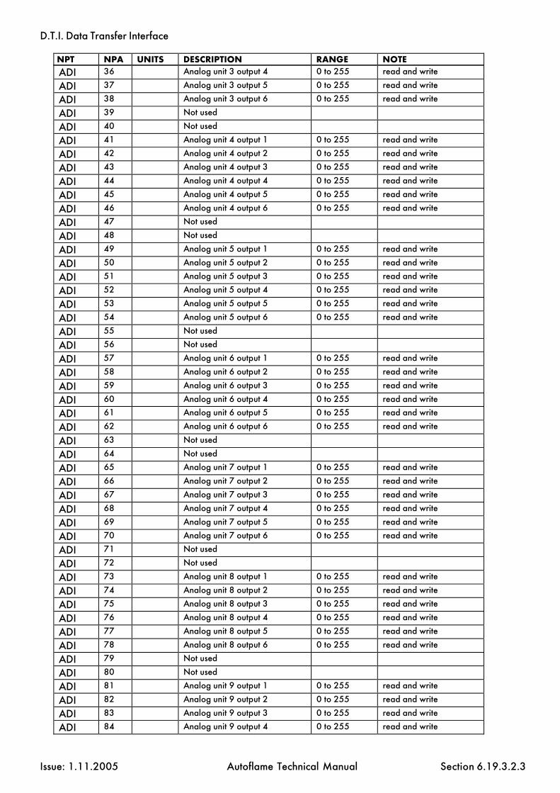
D.T.I. Data Transfer Interface
Issue: 1.11.2005 Autoflame Technical Manual Section
ADI 36 Analog unit 3 output 4 0 to 255 read and write
ADI 37 Analog unit 3 output 5 0 to 255 read and write
ADI 38 Analog unit 3 output 6 0 to 255 read and write
ADI 39 Not used
ADI 40 Not used
ADI 41 Analog unit 4 output 1 0 to 255 read and write
ADI 42 Analog unit 4 output 2 0 to 255 read and write
ADI 43 Analog unit 4 output 3 0 to 255 read and write
ADI 44 Analog unit 4 output 4 0 to 255 read and write
ADI 45 Analog unit 4 output 5 0 to 255 read and write
ADI 46 Analog unit 4 output 6 0 to 255 read and write
ADI 47 Not used
ADI 48 Not used
ADI 49 Analog unit 5 output 1 0 to 255 read and write
ADI 50 Analog unit 5 output 2 0 to 255 read and write
ADI 51 Analog unit 5 output 3 0 to 255 read and write
ADI 52 Analog unit 5 output 4 0 to 255 read and write
ADI 53 Analog unit 5 output 5 0 to 255 read and write
ADI 54 Analog unit 5 output 6 0 to 255 read and write
ADI 55 Not used
ADI 56 Not used
ADI 57 Analog unit 6 output 1 0 to 255 read and write
ADI 58 Analog unit 6 output 2 0 to 255 read and write
ADI 59 Analog unit 6 output 3 0 to 255 read and write
ADI 60 Analog unit 6 output 4 0 to 255 read and write
ADI 61 Analog unit 6 output 5 0 to 255 read and write
ADI 62 Analog unit 6 output 6 0 to 255 read and write
ADI 63 Not used
ADI 64 Not used
ADI 65 Analog unit 7 output 1 0 to 255 read and write
ADI 66 Analog unit 7 output 2 0 to 255 read and write
ADI 67 Analog unit 7 output 3 0 to 255 read and write
ADI 68 Analog unit 7 output 4 0 to 255 read and write
ADI 69 Analog unit 7 output 5 0 to 255 read and write
ADI 70 Analog unit 7 output 6 0 to 255 read and write
ADI 71 Not used
ADI 72 Not used
ADI 73 Analog unit 8 output 1 0 to 255 read and write
ADI 74 Analog unit 8 output 2 0 to 255 read and write
ADI 75 Analog unit 8 output 3 0 to 255 read and write
ADI 76 Analog unit 8 output 4 0 to 255 read and write
ADI 77 Analog unit 8 output 5 0 to 255 read and write
ADI 78 Analog unit 8 output 6 0 to 255 read and write
ADI 79 Not used
ADI 80 Not used
ADI 81 Analog unit 9 output 1 0 to 255 read and write
ADI 82 Analog unit 9 output 2 0 to 255 read and write
ADI 83 Analog unit 9 output 3 0 to 255 read and write
ADI 84 Analog unit 9 output 4 0 to 255 read and write
NPT NPA UNITS DESCRIPTION RANGE NOTE
6.19.3.2.3

D.T.I. Data Transfer Interface
Issue: 1.11.2005 Autoflame Technical Manual Section
ADI 85 Analog unit 9 output 5 0 to 255 read and write
ADI 86 Analog unit 9 output 6 0 to 255 read and write
ADI 87 Not used
ADI 88 Not used
ADI 89 Analog unit 10 output 1 0 to 255 read and write
ADI 90 Analog unit 10 output 2 0 to 255 read and write
ADI 91 Analog unit 10 output 3 0 to 255 read and write
ADI 92 Analog unit 10 output 4 0 to 255 read and write
ADI 93 Analog unit 10 output 5 0 to 255 read and write
ADI 94 Analog unit 10 output 6 0 to 255 read and write
ADI 95 Not used
ADI 96 Not used
ADI 97 Not used
ADI 98 Not used
ADI 99 Not used
ADI 100 Not used
ADI 101 Not used
ADI 102 Not used
ADI 103 Not used
ADI 104 Not used
ADI 105 Not used
ADI 106 Not used
ADI 107 Not used
ADI 108 Not used
ADI 109 Not used
ADI 110 Not used
ADI 111 Not used
ADI 112 Analog unit 1 input 1 0 to 255 read only
ADI 113 Analog unit 1 input 2 0 to 255 read only
ADI 114 Analog unit 1 input 3 0 to 255 read only
ADI 115 Analog unit 1 input 4 0 to 255 read only
ADI 116 Analog unit 1 input 5 0 to 255 read only
ADI 117 Analog unit 1 input 6 0 to 255 read only
ADI 118 Not used
ADI 119 Not used
ADI 120 Analog unit 2 input 1 0 to 255 read only
ADI 121 Analog unit 2 input 2 0 to 255 read only
ADI 122 Analog unit 2 input 3 0 to 255 read only
ADI 123 Analog unit 2 input 4 0 to 255 read only
ADI 124 Analog unit 2 input 5 0 to 255 read only
ADI 125 Analog unit 2 input 6 0 to 255 read only
ADI 126 Not used
ADI 127 Not used
ADI 128 Analog unit 3 input 1 0 to 255 read only
ADI 129 Analog unit 3 input 2 0 to 255 read only
ADI 130 Analog unit 3 input 3 0 to 255 read only
ADI 131 Analog unit 3 input 4 0 to 255 read only
ADI 132 Analog unit 3 input 5 0 to 255 read only
ADI 133 Analog unit 3 input 6 0 to 255 read only
NPT NPA UNITS DESCRIPTION RANGE NOTE
6.19.3.2.4

D.T.I. Data Transfer Interface
Issue: 1.11.2005 Autoflame Technical Manual Section
ADI 134 Not used
ADI 135 Not used
ADI 136 Analog unit 4 input 1 0 to 255 read only
ADI 137 Analog unit 4 input 2 0 to 255 read only
ADI 138 Analog unit 4 input 3 0 to 255 read only
ADI 139 Analog unit 4 input 4 0 to 255 read only
ADI 140 Analog unit 4 input 5 0 to 255 read only
ADI 141 Analog unit 4 input 6 0 to 255 read only
ADI 142 Not used
ADI 143 Not used
ADI 144 Analog unit 5 input 1 0 to 255 read only
ADI 145 Analog unit 5 input 2 0 to 255 read only
ADI 146 Analog unit 5 input 3 0 to 255 read only
ADI 147 Analog unit 5 input 4 0 to 255 read only
ADI 148 Analog unit 5 input 5 0 to 255 read only
ADI 149 Analog unit 5 input 6 0 to 255 read only
ADI 150 Not used
ADI 151 Not used
ADI 152 Analog unit 6 input 1 0 to 255 read only
ADI 153 Analog unit 6 input 2 0 to 255 read only
ADI 154 Analog unit 6 input 3 0 to 255 read only
ADI 155 Analog unit 6 input 4 0 to 255 read only
ADI 156 Analog unit 6 input 5 0 to 255 read only
ADI 157 Analog unit 6 input 6 0 to 255 read only
ADI 158 Not used
ADI 159 Not used
ADI 160 Analog unit 7 input 1 0 to 255 read only
ADI 161 Analog unit 7 input 2 0 to 255 read only
ADI 162 Analog unit 7 input 3 0 to 255 read only
ADI 163 Analog unit 7 input 4 0 to 255 read only
ADI 164 Analog unit 7 input 5 0 to 255 read only
ADI 165 Analog unit 7 input 6 0 to 255 read only
ADI 166 Not used
ADI 167 Not used
ADI 168 Analog unit 8 input 1 0 to 255 read only
ADI 169 Analog unit 8 input 2 0 to 255 read only
ADI 170 Analog unit 8 input 3 0 to 255 read only
ADI 171 Analog unit 8 input 4 0 to 255 read only
ADI 172 Analog unit 8 input 5 0 to 255 read only
ADI 173 Analog unit 8 input 6 0 to 255 read only
ADI 174 Not used
ADI 175 Not used
ADI 176 Analog unit 9 input 1 0 to 255 read only
ADI 177 Analog unit 9 input 2 0 to 255 read only
ADI 178 Analog unit 9 input 3 0 to 255 read only
ADI 179 Analog unit 9 input 4 0 to 255 read only
ADI 180 Analog unit 9 input 5 0 to 255 read only
ADI 181 Analog unit 9 input 6 0 to 255 read only
ADI 182 Not used
NPT NPA UNITS DESCRIPTION RANGE NOTE
6.19.3.2.5

D.T.I. Data Transfer Interface
Issue: 1.11.2005 Autoflame Technical Manual Section
ADI 183 Not used
ADI 184 Analog unit 10 input 1 0 to 255 read only
ADI 185 Analog unit 10 input 2 0 to 255 read only
ADI 186 Analog unit 10 input 3 0 to 255 read only
ADI 187 Analog unit 10 input 4 0 to 255 read only
ADI 188 Analog unit 10 input 5 0 to 255 read only
ADI 189 Analog unit 10 input 6 0 to 255 read only
NPT NPA UNITS DESCRIPTION RANGE NOTE
6.19.3.2.6

D.T.I. Data Transfer Interface
Issue: 1.11.2005 Autoflame Technical Manual Section
NPT NPA UNITS DESCRIPTION RANGE NOTE BDREAD 01 Digital unit 1 input 1 0 or 1 see digital unit setup BDREAD 02 Digital unit 1 input 2 0 or 1 see digital unit setup BDREAD 03 Digital unit 1 input 3 0 or 1 see digital unit setup BDREAD 04 Digital unit 1 input 4 0 or 1 see digital unit setup BDREAD 05 Digital unit 1 input 5 0 or 1 see digital unit setup BDREAD 06 Digital unit 1 input 6 0 or 1 see digital unit setup BDREAD 07 Digital unit 1 input 7 0 or 1 see digital unit setup BDREAD 08 Digital unit 1 input 8 0 or 1 see digital unit setup BDREAD 09 Digital unit 1 input 9 0 or 1 see digital unit setup BDREAD 10 Digital unit 1 input 10 0 or 1 see digital unit setup BDREAD 11 Digital unit 1 input 11 0 or 1 see digital unit setup BDREAD 12 Digital unit 1 input 12 0 or 1 see digital unit setup BDREAD 13 Digital unit 1 input 13 0 or 1 see digital unit setup BDREAD 14 Digital unit 1 input 14 0 or 1 see digital unit setup BDREAD 15 Digital unit 1 input 15 0 or 1 see digital unit setup BDREAD 16 Digital unit 1 input 16 0 or 1 see digital unit setup BDREAD 17 Digital unit 2 input 1 0 or 1 see digital unit setup BDREAD 18 Digital unit 2 input 2 0 or 1 see digital unit setup BDREAD 19 Digital unit 2 input 3 0 or 1 see digital unit setup BDREAD 20 Digital unit 2 input 4 0 or 1 see digital unit setup BDREAD 21 Digital unit 2 input 5 0 or 1 see digital unit setup BDREAD 22 Digital unit 2 input 6 0 or 1 see digital unit setup BDREAD 23 Digital unit 2 input 7 0 or 1 see digital unit setup BDREAD 24 Digital unit 2 input 8 0 or 1 see digital unit setup BDREAD 25 Digital unit 2 input 9 0 or 1 see digital unit setup BDREAD 26 Digital unit 2 input 10 0 or 1 see digital unit setup BDREAD 27 Digital unit 2 input 11 0 or 1 see digital unit setup BDREAD 28 Digital unit 2 input 12 0 or 1 see digital unit setup BDREAD 29 Digital unit 2 input 13 0 or 1 see digital unit setup BDREAD 30 Digital unit 2 input 14 0 or 1 see digital unit setup BDREAD 31 Digital unit 2 input 15 0 or 1 see digital unit setup BDREAD 32 Digital unit 2 input 16 0 or 1 see digital unit setup BDREAD 33 Digital unit 3 input 1 0 or 1 see digital unit setup BDREAD 34 Digital unit 3 input 2 0 or 1 see digital unit setup BDREAD 35 Digital unit 3 input 3 0 or 1 see digital unit setup BDREAD 36 Digital unit 3 input 4 0 or 1 see digital unit setup BDREAD 37 Digital unit 3 input 5 0 or 1 see digital unit setup BDREAD 38 Digital unit 3 input 6 0 or 1 see digital unit setup BDREAD 39 Digital unit 3 input 7 0 or 1 see digital unit setup BDREAD 40 Digital unit 3 input 8 0 or 1 see digital unit setup BDREAD 41 Digital unit 3 input 9 0 or 1 see digital unit setup BDREAD 42 Digital unit 3 input 10 0 or 1 see digital unit setup BDREAD 43 Digital unit 3 input 11 0 or 1 see digital unit setup BDREAD 44 Digital unit 3 input 12 0 or 1 see digital unit setup BDREAD 45 Digital unit 3 input 13 0 or 1 see digital unit setup BDREAD 46 Digital unit 3 input 14 0 or 1 see digital unit setup BDREAD 47 Digital unit 3 input 15 0 or 1 see digital unit setup BDREAD 48 Digital unit 3 input 16 0 or 1 see digital unit setup BDREAD 49 Digital unit 4 input 1 0 or 1 see digital unit setup BDREAD 50 Digital unit 4 input 2 0 or 1 see digital unit setup BDREAD 51 Digital unit 4 input 3 0 or 1 see digital unit setup BDREAD 52 Digital unit 4 input 4 0 or 1 see digital unit setup BDREAD 53 Digital unit 4 input 5 0 or 1 see digital unit setup
6.19.3.2.7

D.T.I. Data Transfer Interface
Issue: 1.11.2005 Autoflame Technical Manual Section
BDREAD 54 Digital unit 4 input 6 0 or 1 see digital unit setup BDREAD 55 Digital unit 4 input 7 0 or 1 see digital unit setup BDREAD 56 Digital unit 4 input 8 0 or 1 see digital unit setup BDREAD 57 Digital unit 4 input 9 0 or 1 see digital unit setup BDREAD 58 Digital unit 4 input 10 0 or 1 see digital unit setup BDREAD 59 Digital unit 4 input 11 0 or 1 see digital unit setup BDREAD 60 Digital unit 4 input 12 0 or 1 see digital unit setup BDREAD 61 Digital unit 4 input 13 0 or 1 see digital unit setup BDREAD 62 Digital unit 4 input 14 0 or 1 see digital unit setup BDREAD 63 Digital unit 4 input 15 0 or 1 see digital unit setup BDREAD 64 Digital unit 4 input 16 0 or 1 see digital unit setup BDREAD 65 Digital unit 5 input 1 0 or 1 see digital unit setup BDREAD 66 Digital unit 5 input 2 0 or 1 see digital unit setup BDREAD 67 Digital unit 5 input 3 0 or 1 see digital unit setup BDREAD 68 Digital unit 5 input 4 0 or 1 see digital unit setup BDREAD 69 Digital unit 5 input 5 0 or 1 see digital unit setup BDREAD 70 Digital unit 5 input 6 0 or 1 see digital unit setup BDREAD 71 Digital unit 5 input 7 0 or 1 see digital unit setup BDREAD 72 Digital unit 5 input 8 0 or 1 see digital unit setup BDREAD 73 Digital unit 5 input 9 0 or 1 see digital unit setup BDREAD 74 Digital unit 5 input 10 0 or 1 see digital unit setup BDREAD 75 Digital unit 5 input 11 0 or 1 see digital unit setup BDREAD 76 Digital unit 5 input 12 0 or 1 see digital unit setup BDREAD 77 Digital unit 5 input 13 0 or 1 see digital unit setup BDREAD 78 Digital unit 5 input 14 0 or 1 see digital unit setup BDREAD 79 Digital unit 5 input 15 0 or 1 see digital unit setup BDREAD 80 Digital unit 5 input 16 0 or 1 see digital unit setup BDREAD 81 Digital unit 6 input 1 0 or 1 see digital unit setup BDREAD 82 Digital unit 6 input 2 0 or 1 see digital unit setup BDREAD 83 Digital unit 6 input 3 0 or 1 see digital unit setup BDREAD 84 Digital unit 6 input 4 0 or 1 see digital unit setup BDREAD 85 Digital unit 6 input 5 0 or 1 see digital unit setup BDREAD 86 Digital unit 6 input 6 0 or 1 see digital unit setup BDREAD 87 Digital unit 6 input 7 0 or 1 see digital unit setup BDREAD 88 Digital unit 6 input 8 0 or 1 see digital unit setup BDREAD 89 Digital unit 6 input 9 0 or 1 see digital unit setup BDREAD 90 Digital unit 6 input 10 0 or 1 see digital unit setup BDREAD 91 Digital unit 6 input 11 0 or 1 see digital unit setup BDREAD 92 Digital unit 6 input 12 0 or 1 see digital unit setup BDREAD 93 Digital unit 6 input 13 0 or 1 see digital unit setup BDREAD 94 Digital unit 6 input 14 0 or 1 see digital unit setup BDREAD 95 Digital unit 6 input 15 0 or 1 see digital unit setup BDREAD 96 Digital unit 6 input 16 0 or 1 see digital unit setup BDREAD 97 Digital unit 7 input 1 0 or 1 see digital unit setup BDREAD 98 Digital unit 7 input 2 0 or 1 see digital unit setup BDREAD 99 Digital unit 7 input 3 0 or 1 see digital unit setup BDREAD 100 Digital unit 7 input 4 0 or 1 see digital unit setup BDREAD 101 Digital unit 7 input 5 0 or 1 see digital unit setup BDREAD 102 Digital unit 7 input 6 0 or 1 see digital unit setup BDREAD 103 Digital unit 7 input 7 0 or 1 see digital unit setup BDREAD 104 Digital unit 7 input 8 0 or 1 see digital unit setup BDREAD 105 Digital unit 7 input 9 0 or 1 see digital unit setup BDREAD 106 Digital unit 7 input 10 0 or 1 see digital unit setup BDREAD 107 Digital unit 7 input 11 0 or 1 see digital unit setup
NPT NPA UNITS DESCRIPTION RANGE NOTE
6.19.3.2.8

D.T.I. Data Transfer Interface
Issue: 1.11.2005 Autoflame Technical Manual Section
BDREAD 108 Digital unit 7 input 12 0 or 1 see digital unit setup BDREAD 109 Digital unit 7 input 13 0 or 1 see digital unit setup BDREAD 110 Digital unit 7 input 14 0 or 1 see digital unit setup BDREAD 111 Digital unit 7 input 15 0 or 1 see digital unit setup BDREAD 112 Digital unit 7 input 16 0 or 1 see digital unit setup BDREAD 113 Digital unit 8 input 1 0 or 1 see digital unit setup BDREAD 114 Digital unit 8 input 2 0 or 1 see digital unit setup BDREAD 115 Digital unit 8 input 3 0 or 1 see digital unit setup BDREAD 116 Digital unit 8 input 4 0 or 1 see digital unit setup BDREAD 117 Digital unit 8 input 5 0 or 1 see digital unit setup BDREAD 118 Digital unit 8 input 6 0 or 1 see digital unit setup BDREAD 119 Digital unit 8 input 7 0 or 1 see digital unit setup BDREAD 120 Digital unit 8 input 8 0 or 1 see digital unit setup BDREAD 121 Digital unit 8 input 9 0 or 1 see digital unit setup BDREAD 122 Digital unit 8 input 10 0 or 1 see digital unit setup BDREAD 123 Digital unit 8 input 11 0 or 1 see digital unit setup BDREAD 124 Digital unit 8 input 12 0 or 1 see digital unit setup BDREAD 125 Digital unit 8 input 13 0 or 1 see digital unit setup BDREAD 126 Digital unit 8 input 14 0 or 1 see digital unit setup BDREAD 127 Digital unit 8 input 15 0 or 1 see digital unit setup BDREAD 128 Digital unit 8 input 16 0 or 1 see digital unit setup BDREAD 129 Digital unit 9 input 1 0 or 1 see digital unit setup BDREAD 130 Digital unit 9 input 2 0 or 1 see digital unit setup BDREAD 131 Digital unit 9 input 3 0 or 1 see digital unit setup BDREAD 132 Digital unit 9 input 4 0 or 1 see digital unit setup BDREAD 133 Digital unit 9 input 5 0 or 1 see digital unit setup BDREAD 134 Digital unit 9 input 6 0 or 1 see digital unit setup BDREAD 135 Digital unit 9 input 7 0 or 1 see digital unit setup BDREAD 136 Digital unit 9 input 8 0 or 1 see digital unit setup BDREAD 137 Digital unit 9 input 9 0 or 1 see digital unit setup BDREAD 138 Digital unit 9 input 10 0 or 1 see digital unit setup BDREAD 139 Digital unit 9 input 11 0 or 1 see digital unit setup BDREAD 140 Digital unit 9 input 12 0 or 1 see digital unit setup BDREAD 141 Digital unit 9 input 13 0 or 1 see digital unit setup BDREAD 142 Digital unit 9 input 14 0 or 1 see digital unit setup BDREAD 143 Digital unit 9 input 15 0 or 1 see digital unit setup BDREAD 144 Digital unit 9 input 16 0 or 1 see digital unit setup BDREAD 145 Digital unit 10 input 1 0 or 1 see digital unit setup BDREAD 146 Digital unit 10 input 2 0 or 1 see digital unit setup BDREAD 147 Digital unit 10 input 3 0 or 1 see digital unit setup BDREAD 148 Digital unit 10 input 4 0 or 1 see digital unit setup BDREAD 149 Digital unit 10 input 5 0 or 1 see digital unit setup BDREAD 150 Digital unit 10 input 6 0 or 1 see digital unit setup BDREAD 151 Digital unit 10 input 7 0 or 1 see digital unit setup BDREAD 152 Digital unit 10 input 8 0 or 1 see digital unit setup BDREAD 153 Digital unit 10 input 9 0 or 1 see digital unit setup BDREAD 154 Digital unit 10 input 10 0 or 1 see digital unit setup BDREAD 155 Digital unit 10 input 11 0 or 1 see digital unit setup BDREAD 156 Digital unit 10 input 12 0 or 1 see digital unit setup BDREAD 157 Digital unit 10 input 13 0 or 1 see digital unit setup BDREAD 158 Digital unit 10 input 14 0 or 1 see digital unit setup BDREAD 159 Digital unit 10 input 15 0 or 1 see digital unit setup BDREAD 160 Digital unit 10 input 16 0 or 1 see digital unit setup
NPT NPA UNITS DESCRIPTION RANGE NOTE
6.19.3.2.9

D.T.I. Data Transfer Interface
Issue: 1.11.2005 Autoflame Technical Manual Section
BDREAD 161 MM 1 on/off line status 0 = off line 1 = on line
BDREAD 162 MM 2 on/off line status 0 = off line 1 = on line
BDREAD 163 MM 3 on/off line status 0 = off line 1 = on line
BDREAD 164 MM 4 on/off line status 0 = off line 1 = on line
BDREAD 165 MM 5 on/off line status 0 = off line 1 = on line
BDREAD 166 MM 6 on/off line status 0 = off line 1 = on line
BDREAD 167 MM 7 on/off line status 0 = off line 1 = on line
BDREAD 168 MM 8 on/off line status 0 = off line 1 = on line
BDREAD 169 MM 9 on/off line status 0 = off line 1 = on line
BDREAD 170 MM 10 on/off line status 0 = off line 1 = on line
BDREAD 171-192
Not used
BDREAD 193 Digital unit 1 on/off line status 0 = off line 1 = on line
read only
BDREAD 194 Digital unit 2 on/off line status 0 = off line 1 = on line
read only
BDREAD 195 Digital unit 3 on/off line status 0 = off line 1 = on line
read only
BDREAD 196 Digital unit 4 on/off line status 0 = off line 1 = on line
read only
BDREAD 197 Digital unit 5 on/off line status 0 = off line 1 = on line
read only
BDREAD 198 Digital unit 6 on/off line status 0 = off line 1 = on line
read only
BDREAD 199 Digital unit 7 on/off line status 0 = off line 1 = on line
read only
BDREAD 200 Digital unit 8 on/off line status 0 = off line 1 = on line
read only
BDREAD 201 Digital unit 9 on/off line status 0 = off line 1 = on line
read only
BDREAD 202 Digital unit 10 on/off line status 0 = off line 1 = on line
read only
BDREAD 203 Not used BDREAD 204 Not used BDREAD 205 Not used BDREAD 206 Not used BDREAD 207 Not used BDREAD 208 Not used BDREAD 209 Analog unit 1 on/off line status 0 = off line
1 = on line read only
BDREAD 210 Analog unit 2 on/off line status 0 = off line 1 = on line
read only
BDREAD 211 Analog unit 3 on/off line status 0 = off line 1 = on line
read only
BDREAD 212 Analog unit 4 on/off line status 0 = off line 1 = on line
read only
BDREAD 213 Analog unit 5 on/off line status 0 = off line 1 = on line
read only
BDREAD 214 Anal4og unit 6 on/off line status 0 = off line 1 = on line
read only
NPT NPA UNITS DESCRIPTION RANGE NOTE
6.19.3.2.10

D.T.I. Data Transfer Interface
Issue: 1.11.2005 Autoflame Technical Manual Section
BDREAD 215 Analog unit 7 on/off line status 0 = off line 1 = on line
read only
BDREAD 216 Analog unit 8 on/off line status 0 = off line 1 = on line
read only
BDREAD 217 Analog unit 9 on/off line status 0 = off line 1 = on line
read only
BDREAD 218 Analog unit 10 on/off line status 0 = off line 1 = on line
read only
NPT NPA UNITS DESCRIPTION RANGE NOTE
6.19.3.2.11

D.T.I. Data Transfer Interface
Issue: 1.11.2005 Autoflame Technical Manual Section
NPT NPA UNITS DESCRIPTION RANGE NOTE BDWRITE 1 MM 1 Enable/disable 1 = off line
0 = on line write only
BDWRITE 2 MM 2 Enable/disable 1 = off line 0 = on line
write only
BDWRITE 3 MM 3 Enable/disable 1 = off line 0 = on line
write only
BDWRITE 4 MM 4 Enable/disable 1 = off line 0 = on line
write only
BDWRITE 5 MM 5 Enable/disable 1 = off line 0 = on line
write only
BDWRITE 6 MM 6 Enable/disable 1 = off line 0 = on line
write only
BDWRITE 7 MM 7 Enable/disable 1 = off line 0 = on line
writ only
BDWRITE 8 MM 8 Enable/disable 1 = off line 0 = on line
write only
BDWRITE 9 MM 9 Enable/disable 1 = off line 0 = on line
write only
BDWRITE 10 MM 10 Enable/disable 1 = off line 0 = on line
write only
BDWRITE 11 Not used BDWRITE 12 Not used BDWRITE 13 Not used BDWRITE 14 Not used BDWRITE 15 Not used BDWRITE 16 Not used BDWRITE 17 Digital unit 1 output 1 0 = off, 1 = on write only BDWRITE 18 Digital unit 1 output 2 0 = off, 1 = on write only BDWRITE 19 Digital unit 1 output 3 0 = off, 1 = on write only BDWRITE 20 Digital unit 1 output 4 0 = off, 1 = on write only BDWRITE 21 Digital unit 1 output 5 0 = off, 1 = on write only BDWRITE 22 Digital unit 1 output 6 0 = off, 1 = on write only BDWRITE 23 Digital unit 1 output 7 0 = off, 1 = on write only BDWRITE 24 Digital unit 1 output 8 0 = off, 1 = on write only BDWRITE 25 Digital unit 2 output 1 0 = off, 1 = on write only BDWRITE 26 Digital unit 2 output 2 0 = off, 1 = on write only BDWRITE 27 Digital unit 2 output 3 0 = off, 1 = on write only BDWRITE 28 Digital unit 2 output 4 0 = off, 1 = on write only BDWRITE 29 Digital unit 2 output 5 0 = off, 1 = on write only BDWRITE 30 Digital unit 2 output 6 0 = off, 1 = on write only BDWRITE 31 Digital unit 2 output 7 0 = off, 1 = on write only BDWRITE 32 Digital unit 2 output 8 0 = off, 1 = on write only BDWRITE 33 Digital unit 3 output 1 0 = off, 1 = on write only BDWRITE 34 Digital unit 3 output 2 0 = off, 1 = on write only BDWRITE 35 Digital unit 3 output 3 0 = off, 1 = on write only BDWRITE 36 Digital unit 3 output 4 0 = off, 1 = on write only BDWRITE 37 Digital unit 3 output 5 0 = off, 1 = on write only BDWRITE 38 Digital unit 3 output 6 0 = off, 1 = on write only BDWRITE 39 Digital unit 3 output 7 0 = off, 1 = on write only BDWRITE 40 Digital unit 3 output 8 0 = off, 1 = on write only BDWRITE 41 Digital unit 4 output 1 0 = off, 1 = on write only BDWRITE 42 Digital unit 4 output 2 0 = off, 1 = on write only BDWRITE 43 Digital unit 4 output 3 0 = off, 1 = on write only BDWRITE 44 Digital unit 4 output 4 0 = off, 1 = on write only BDWRITE 45 Digital unit 4 output 5 0 = off, 1 = on write only
6.19.3.2.12

D.T.I. Data Transfer Interface
Issue: 1.11.2005 Autoflame Technical Manual Section
BDWRITE 46 Digital unit 4 output 6 0 = off, 1 = on write only BDWRITE 47 Digital unit 4 output 7 0 = off, 1 = on write only BDWRITE 48 Digital unit 4 output 8 0 = off, 1 = on write only BDWRITE 49 Digital unit 5 output 1 0 = off, 1 = on write only BDWRITE 50 Digital unit 5 output 2 0 = off, 1 = on write only BDWRITE 51 Digital unit 5 output 3 0 = off, 1 = on write only BDWRITE 52 Digital unit 5 output 4 0 = off, 1 = on write only BDWRITE 53 Digital unit 5 output 5 0 = off, 1 = on write only BDWRITE 54 Digital unit 5 output 6 0 = off, 1 = on write only BDWRITE 55 Digital unit 5 output 7 0 = off, 1 = on write only BDWRITE 56 Digital unit 5 output 8 0 = off, 1 = on write only BDWRITE 57 Digital unit 6 output 1 0 = off, 1 = on write only BDWRITE 58 Digital unit 6 output 2 0 = off, 1 = on write only BDWRITE 59 Digital unit 6 output 3 0 = off, 1 = on write only BDWRITE 60 Digital unit 6 output 4 0 = off, 1 = on write only BDWRITE 61 Digital unit 6 output 5 0 = off, 1 = on write only BDWRITE 62 Digital unit 6 output 6 0 = off, 1 = on write only BDWRITE 63 Digital unit 6 output 7 0 = off, 1 = on write only BDWRITE 64 Digital unit 6 output 8 0 = off, 1 = on write only BDWRITE 65 Digital unit 7 output 1 0 = off, 1 = on write only BDWRITE 66 Digital unit 7 output 2 0 = off, 1 = on write only BDWRITE 67 Digital unit 7 output 3 0 = off, 1 = on write only BDWRITE 68 Digital unit 7 output 4 0 = off, 1 = on write only BDWRITE 69 Digital unit 7 output 5 0 = off, 1 = on write only BDWRITE 70 Digital unit 7 output 6 0 = off, 1 = on write only BDWRITE 71 Digital unit 7 output 7 0 = off, 1 = on write only BDWRITE 72 Digital unit 7 output 8 0 = off, 1 = on write only BDWRITE 73 Digital unit 8 output 1 0 = off, 1 = on write only BDWRITE 74 Digital unit 8 output 2 0 = off, 1 = on write only BDWRITE 75 Digital unit 8 output 3 0 = off, 1 = on write only BDWRITE 76 Digital unit 8 output 4 0 = off, 1 = on write only BDWRITE 77 Digital unit 8 output 5 0 = off, 1 = on write only BDWRITE 78 Digital unit 8 output 6 0 = off, 1 = on write only BDWRITE 79 Digital unit 8 output 7 0 = off, 1 = on write only BDWRITE 80 Digital unit 8 output 8 0 = off, 1 = on write only BDWRITE 81 Digital unit 9 output 1 0 = off, 1 = on write only BDWRITE 82 Digital unit 9 output 2 0 = off, 1 = on write only BDWRITE 83 Digital unit 9 output 3 0 = off, 1 = on write only BDWRITE 84 Digital unit 9 output 4 0 = off, 1 = on write only BDWRITE 85 Digital unit 9 output 5 0 = off, 1 = on write only BDWRITE 86 Digital unit 9 output 6 0 = off, 1 = on write only BDWRITE 87 Digital unit 9 output 7 0 = off, 1 = on write only BDWRITE 88 Digital unit 9 output 8 0 = off, 1 = on write only BDWRITE 89 Digital unit 10 output 1 0 = off, 1 = on write only BDWRITE 90 Digital unit 10 output 2 0 = off, 1 = on write only BDWRITE 91 Digital unit 10 output 3 0 = off, 1 = on write only BDWRITE 92 Digital unit 10 output 4 0 = off, 1 = on write only BDWRITE 93 Digital unit 10 output 5 0 = off, 1 = on write only BDWRITE 94 Digital unit 10 output 6 0 = off, 1 = on write only BDWRITE 95 Digital unit 10 output 7 0 = off, 1 = on write only BDWRITE 96 Digital unit 10 output 8 0 = off, 1 = on write only
NPT NPA UNITS DESCRIPTION RANGE NOTE
6.19.3
D.T.I. Data Transfer Interface
Issue: 1.11.2005 Autoflame Technical Manual Section
6.20 OTHER INFORMATION AND ILLUSTRATIONS
6.20.1 Loop Back Test
A facility exists which enables the hardware connection to the RS-232 PC port and the RS-422 portto be checked.
On the dual inline switch (switch bank 2) set way 5 on and all other ways off.
Any character on the receive line is then echoed back immediately on the transmit line.
This facility is intended to be used in conjunction with a terminal emulator, such Hyperterminal(hypertrm.exe) which is included with Windows.
The communications settings should be as follows:
Bits per second: 9600Data bits: 8Parity: noneStop bits: 1Flow control: None (i.e. no hardware or software flow control)
Full duplex.
Other Information and Illustrations
6.20.1

D.T.I. Data Transfer Interface
Issue: 1.11.2005 Autoflame Technical Manual Section 6.20.2
6.20.2 Communication Interfaces
This page is for information only.
Example of a network
FULLDUPLEX
RS 232
FULLDUPLEX
RS 422
1 Km
TX
RX
RX
TX
A B
I=0I=1
RS 485
HALFDUPLEX
TX/RX SWITCH
A BTX RX RX TX
TX/RX SWITCH
< 10 meters
0 1-8v +8vTX
RX
SG
RX
TX
SG
A B
0 1-8v +8v
Other Information and Illustrations

D.T.I. Data Transfer Interface
Issue: 1.11.2005 Autoflame Technical Manual Section

Application Possibilities
Issue: 1.11.2005 Autoflame Technical Manual Section
Section 7: Application Possibilities for M.M./E.G.A.
7.1 Pressure Jet/Gun Type Burners
7.2 Rotary Burners
7.2.1 Diagram showing System with Rotary Burner
7.3 Flue Gas Recirculation Control (NOx).
7.4 Steam Generator Feed Water Control
7.5 Water Injection
7.7 System Configurations
7.7.1 Mk.6 EVO MM/EGA System Schematic7.7.2 Mini Mk.6 MM/EGA System Schematic7.7.3 Mini Mk.5 EVO MM/EGA System Schematic
7: Index
123456789012345678901234561234567890123456789012345612345678901234567890123456123456789012345678901234561234567890123456789012345612345678901234567890123456123456789012345678901234561234567890123456789012345612345678901234567890123456123456789012345678901234561234567890123456789012345612345678901234567890123456

Application Possibilities
Issue: 1.11.2005 Autoflame Technical Manual Section
Pressure Jet/Gun Type Burners
7.1 APPLICATION POSSIBILITIES FOR M.M. /E.G.A. SYSTEM
The M.M. system is basically a fuel/air ratio control designed to improve the energy efficiency andcontrol of a standard pressure jet or rotary burner. The ability to control up to 6 channels howevergreatly expands the areas in which it can be used and any application in which it is necessary toprecisely mix fuel and air from up to 6 sources is a possibility.
Pressure Jet/Gun Type Burners
The simplest system requiring only two servo motors for control. The energy saving benefits come fromfour sources:
a.) Elimination of mechanical hysteresis due to cams and linkages.
b.) Precise control of the fuel/air ratio throughout the combustion range without the compromiseswhich limit a cam.
c.) Control of the output to ±1 degree C. (± 2 degrees F.) or ±1.5 psi via the PID controller,eliminating the wastage or pressure higher than required.
d.) No compromise required when changing between fuels since the air/fuel ratio for each arecompletely seperate.
7.1
Application Possibilities
Issue: 1.11.2005 Autoflame Technical Manual Section
Rotary Burners
The M.M. system is basically a fuel/air ratio control designed to improve the energy efficiency andcontrol of a standard pressure jet or rotary burner.
The ability to control up to 6 channels however greatly expands the areas in which it can be used.Any application in which it is necessary to precisely mix fuel and air from up to 8 sources is a possibilityand one of the possible applications is the use of rotary burners.
The benefits of this system are similar to that of pressure jet/gun burners but by utilising the thirdchannel , to control the primary air supply, the best possible mixing is achieved. The energy savingbenefits are as follows:
a.) Elimination of mechanical hysteresis due to cams and linkages;
b.) Precise control of the fuel/air ratio throughout the combustion range without the compromiseswhich limit a cam.
c.) Control of the output to ±1 degree C. (± 2 degrees F.) or ± 1.5 psi via the P.I.D. controller,eliminating the wastage or pressure higher than required.
d.) No compromise required when changing between fuels since the air/fuel ratio for each arecompletely seperate.
7.2 APPLICATION POSSIBILITIES FOR M.M. /E.G.A. SYSTEM
Rotary Burners
7.2

Application Possibilities
Issue: 1.11.2005 Autoflame Technical Manual Section 7.2.1

Application Possibilities
Issue: 1.11.2005 Autoflame Technical Manual Section
The M.M. system is basically an air/fuel ratio control designed to improve the energy efficiency andcontrol of a standard pressure jet or rotary burner. The ability to control up to 8 channels howevergreatly expands the areas in which it can be used and any application in which it is necessary toprecisely mix fuel and air from up to 6 sources is a possibility.
The additional channels can be used to control a recirculation damper which is a common method inthe control of NOX production. As with most forms of NOX control this method reduces thetemperature in the combustion chamber and hence reduces thermal efficiency. Use of the M.M./E.G.A.will minimise the excess air to the burner which itself reduces NOX and will also affect some of this lossof efficiency.
7.3 APPLICATION POSSIBILITIES FOR M.M. /E.G.A. SYSTEM
Flue Gas Re-Circulation Control (NOx)
7.3

Application Possibilities
Issue: 1.11.2005 Autoflame Technical Manual Section
7.4 APPLICATION POSSIBILITIES FOR M.M. /E.G.A. SYSTEM
Steam Generator Feed Water Control
The M.M. system is basically an air/fuel ratio control designed to improve the energy efficiency andcontrol of a standard pressure jet or rotary burner. The ability to control up to 8 channels howevergreatly expands the areas in which it can be used and any application in which it is necessary toprecisely mix fuel and air from up to 6 sources is a possibility.
Steam Generator Feed Water Control
7.4

Application Possibilities
Issue: 1.11.2005 Autoflame Technical Manual Section
7.5 APPLICATION POSSIBILITIES FOR M.M. /E.G.A. SYSTEM
Water Injection
The M.M. system is basically an air/fuel ratio control designed to improve the energy efficiency andcontrol of a standard pressure jet or rotary burner. The ability to control up to 8 channels howevergreatly expands the areas in which it can be used and any application in which it is necessary toprecisely mix fuel and air from up to 6 sources is a possibility.
The 3rd channel can be used in this instance to control the water injection.
Water Injection
7.5

Application Possibilities
Issue: 1.11.2005 Autoflame Technical Manual Section 7.7.1
7.7.1 MK6 EVO MM/EGA
SENSOR SERVO
SWITCH
EXTERNAL
DRIVECH.5SPEEDVARIABLE FLAMEOR
DRAFTFORCED AUX.
SERVO
CH.4AIR AUX.
SERVOSERVO
CH.3CH.2U.V
LOAD OR
OIL
AIRPRESSURE
PRESSURESENSOR
OIL
CH.1
FUEL
PRESSURESENSOR
GAS
GAS
HIGH/LOW GASPRESSURE PROVING
VALVE PROVING
SENSOR
EXTERNAL
STEAMSENSOR

Application Possibilities
Issue: 1.11.2005A
utoflame Technical M
anualSection
7.7
.2M
INI M
K6
MM
/EGA
7.7.2
SENSOR SERVO
SECOND SETPOINT FACILITEXTERNAL MODULATION
SWITCH
EXTERNAL
BOILER
DRIVECH.4SPEEDVARIABLE FLAMEOR
DRAFTFORCED AUX.
SERVO
CH.4AIR AUX.
SERVOSERVO
CH.3CH.2U.V
LOAD OR
OIL
AIRPRESSURE
PRESSURESENSOR
OIL
CH.1
FUEL
PRESSURESENSOR
GAS
GAS
HIGH/LOW GASPRESSURE PROVING
VALVE PROVING
SENSOR
PROBESAMPLING
FLUE
EXTERNAL
STEAMSENSOR
OR

Application Possibilities
Issue: 1.11.2005A
utoflame Technical M
anualSection
7.7.3
7.7
.3M
INI M
K5
EVO
MM
/EGASWITCH SERVO
SECOND SETPOINT FACILITYEXTERNAL MODULATION
BOILERDRAFT
FORCED AIR AUX.SERVOSERVO
CH.3CH.2U.V
OIL
AIRPRESSURE
CH.1
FUEL
GAS
PROBESAMPLING
FLUE
STEAMSENSOR
OR FLAME ROD

M.M./E.G.A. Peripherals
Issue: 1.11.2005 Autoflame Technical Manual Section
Section 8: Ancillary & Peripheral Equipment.
8: Index
8.0 Valve Specifications
8.0.1 Oil Valve Selection
8.1 Screwed Gas Valves (small positioning motor)8.2 Flanged Gas Valves (small positioning motor)8.3 Flanged Gas Valves (large positioning motor)
8.3.1 Screwed Gas Valve + Oil Valve + Small positioning motor8.3.2 Flanged Gas Valve + Oil Valve + Small positioning motor8.3.3 Gas Valve Pressure Drop Graph
8.4 Type 1,2,5,6,8,9, Oil Control ValvesSmall positioning motor8.4.1 Small Metering Valve
8.5 Type 4 Oil Control ValveLarge positioning motor
8.6 Type 3 Oil Control ValveLarge positioning motor
8.6.1 Type 1 Spillback Graph8.6.2 Type 2 Spillback Graph8.6.3 Type 4 Spillback Graph8.6.4 Type 5 Spillback Graph8.6.5 Type 3 Metering Graph8.6.6 Type 6 Metering Graph8.6.7 Type 8 Metering Graph8.6.8 Type 9 Metering Graph
8.7 Small Positioning Motor
8.8 Large Positioning Motor
8.9 Temperature Detector8.9.1 Pressure Detector
8.10 Industrial Positioning Motor
8.10.0 Overview8.10.1 External Drawings8.10.2 Specification8.10.3 Installation8.10.4 Manual Operation8.10.5 Troubleshooting
12345678901234567890123123456789012345678901231234567890123456789012312345678901234567890123123456789012345678901231234567890123456789012312345678901234567890123123456789012345678901231234567890123456789012312345678901234567890123123456789012345678901231234567890123456789012312345678901234567890123
1
Gas Valves:
Oil Valves:
Positioning Motors:
Load Detectors:

M.M./E.G.A. Peripherals
Issue: 1.11.2005 Autoflame Technical Manual Section
8.0 VALVE SPECIFICATIONS
When using high viscosity low temperature fuel oils through smaller valves, turbulent flowcharacteristics can reduce volume throughput significantly.
All flow pressure graphs published for oil valves are using Light distillate oil @ 20°C and a viscosityof 5 centistokes.
Autoflame will carry out flow characteristic tests on specific valves against customer fuel/viscosityand temperature specifications. Price on application.
Standard oil valve build execution is stainless steel valve body with cast bronze metering bobbin.The top and bottom closing plates are aluminium.
All valves can be supplied in non-standard material at extra cost, price on application.
For very heavy fuel oil or contaminated fuels it is recommended that execution is a stainless steelbobbin. The cost for all stainless steel construction is standard price x3.
Gas Valve's standard execution is an aluminium body with stainless steel metering disk. Gas valvescan also be supplied for corrosive/contaminated fuels in all stainless steel construction at standardprice x4.
Maximum pressure is 350 psi (oil valves); 10 psi (GV4 gas valves); 25psi (GVF gas valves).
For further information please contact your supplier.
8.0
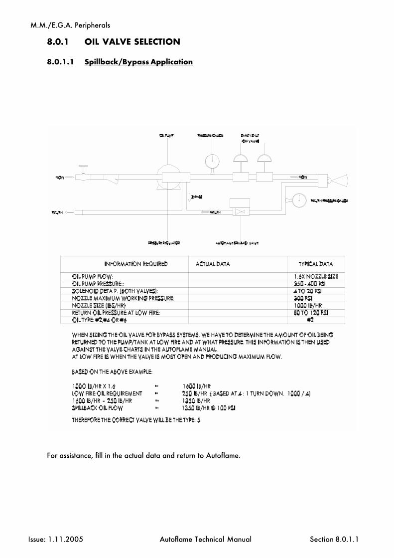
M.M./E.G.A. Peripherals
Issue: 1.11.2005 Autoflame Technical Manual Section
8.0.1 OIL VALVE SELECTION
8.0.1.1 Spillback/Bypass Application
8.0.1.1
For assistance, fill in the actual data and return to Autoflame.

M.M./E.G.A. Peripherals
Issue: 1.11.2005 Autoflame Technical Manual Section
8.0.1.2 Metering/Simplex Application
8.0.1.2
For assistance, fill in the fields below and return to Autoflame:
A: ________
C: ________
D: ________

M.M./E.G.A. Peripherals
Issue: 1.11.2005 Autoflame Technical Manual Section 8.1

M.M./E.G.A. Peripherals
Issue: 1.11.2005 Autoflame Technical Manual Section 8.1.a

M.M./E.G.A. Peripherals
Issue: 1.11.2005 Autoflame Technical Manual Section 8.2

M.M./E.G.A. Peripherals
Issue: 1.11.2005 Autoflame Technical Manual Section 8.2.a

M.M./E.G.A. Peripherals
Issue: 1.11.2005 Autoflame Technical Manual Section 8.3
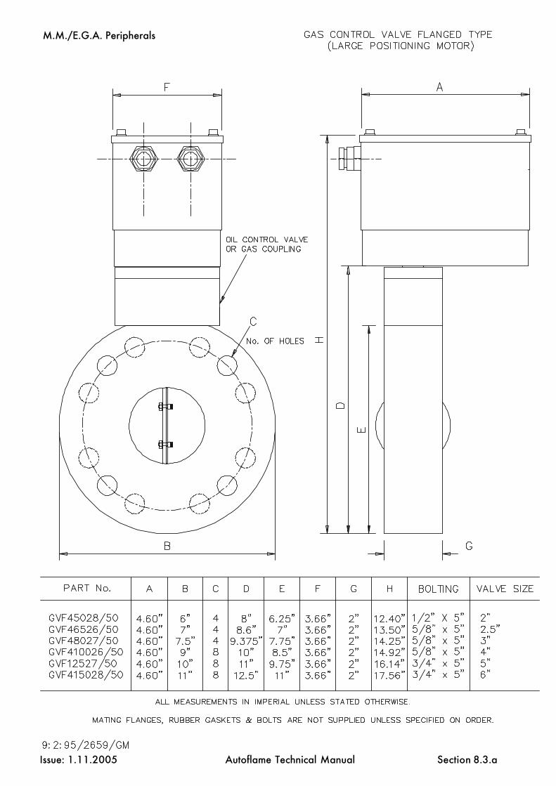
M.M./E.G.A. Peripherals
Issue: 1.11.2005 Autoflame Technical Manual Section 8.3.a

M.M./E.G.A. Peripherals
Issue: 1.11.2005 Autoflame Technical Manual Section 8.3.1

M.M./E.G.A. Peripherals
Issue: 1.11.2005 Autoflame Technical Manual Section 8.3.2

M.M./E.G.A. Peripherals
Issue: 1.11.2005 Autoflame Technical Manual Section 8.3.2a

M.M./E.G.A. Peripherals
Issue: 1.11.2005 Autoflame Technical Manual Section 8.3.3

M.M./E.G.A. Peripherals
Issue: 1.11.2005 Autoflame Technical Manual Section 8.4

M.M./E.G.A. Peripherals
Issue: 1.11.2005 Autoflame Technical Manual Section20.08.97 8.4.1

M.M./E.G.A. Peripherals
Issue: 1.11.2005 Autoflame Technical Manual Section 8.5

M.M./E.G.A. Peripherals
Issue: 1.11.2005 Autoflame Technical Manual Section 8.6

M.M./E.G.A. Peripherals
Issue: 1.11.2005 Autoflame Technical Manual Section 8.6.1

M.M./E.G.A. Peripherals
Issue: 1.11.2005 Autoflame Technical Manual Section 8.6.2

M.M./E.G.A. Peripherals
Issue: 1.11.2005 Autoflame Technical Manual Section 8.6.3

M.M./E.G.A. Peripherals
Issue: 1.11.2005 Autoflame Technical Manual Section 8.6.4

M.M./E.G.A. Peripherals
Issue: 1.11.2005 Autoflame Technical Manual Section 8.6.5
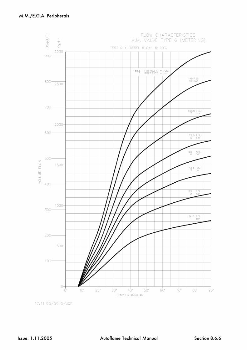
M.M./E.G.A. Peripherals
Issue: 1.11.2005 Autoflame Technical Manual Section 8.6.6

M.M./E.G.A. Peripherals
Issue: 1.11.2005 Autoflame Technical Manual Section 8.6.7

M.M./E.G.A. Peripherals
Issue: 1.11.2005 Autoflame Technical Manual Section 8.6.8

M.M./E.G.A. Peripherals
Issue: 1.11.2005 Autoflame Technical Manual Section 8.7

M.M./E.G.A. Peripherals
Issue: 1.11.2005 Autoflame Technical Manual Section 8.7.1
M.M./E.G.A. Small Positioning Motor
noitacificepS
egatloVylppuS zH06/05,V032/42
euqroTtfahStuptuO mN2.1
elgnAgnitarepO °09-0
emiTgnitarepO sdnoces02lanimoN
rewoPdetaRxaM W3
erutarepmeTtneibmA F°041otF°23/C°06otC°0
gnitaRnoitcetorPlairtsudnI 31AMEN/45PI
elgnAgnitnuoM °063
gninoitisoP evirDMM
rotoMevirD suonorhcnyS
lairetaMydoB 4RCleetSdliM
gnitaoC taoCredwoP007nopretnI
thgieW gk55.0
snoisnemiD mm46x29x99
noitcennoCgniriW dnalG11GP
Tamper Proof Screws
Potentiometer
M4 Earth Stud
P.C.B./1 Fixing Points M3
Potentiometer Adjusting Clips
Positioning MotorFixing Holes 5mm (7/ 32") Diameter

M.M./E.G.A. Peripherals
Issue: 1.11.2005 Autoflame Technical Manual Section 8.8

M.M./E.G.A. Peripherals
Issue: 1.11.2005 Autoflame Technical Manual Section 8.8.1
M.M./E.G.A. Large Positioning Motor
noitacificepS
egatloVylppuS zH06/05,V032/42
euqroTtfahStuptuO mN51
elgnAgnitarepO °09-0
emiTgnitarepO sdnoces03lanimoN
rewoPdetaRxaM W9
erutarepmeTtneibmA F°041otF°23/C°06otC°0
gnitaRnoitcetorPlairtsudnI 31AMEN/45PI
elgnAgnitnuoM °063
gninoitisoP evirDMM
rotoMevirD suonorhcnyS
lairetaMydoB 4RCleetSdliM
gnitaoC taoCredwoP007nopretnI
thgieW gk58.1
snoisnemiD 49x211x541
noitcennoCgniriW dnalG11GP
PotentiometerTamper Proof Screws
M4 Earth Stud
Positioning MotorFixing Holes 5mm (7/32") Diameter
P.C.B./1 Fixing Points M3
Potentiometer Adjusting Clips

M.M./E.G.A. Peripherals
Issue: 1.11.2005 Autoflame Technical Manual Section 8.9
Autoflame Boiler Water Temperature SensorPart No. MM10006

M.M./E.G.A. Peripherals
Issue: 1.11.2005 Autoflame Technical Manual Section
NB: Any physical damage to the stainless steel diaphram may result in sensor failure. The maximum depth that a male fitting can be screwed into the sensor is 10mm.
8.9.1
Autoflame Boiler Steam Pressure SensorPart No. MM10008/9/10
snoitcennoC
rosneS 6kMiniM/6kM 5kMiniM
neerG 83 16
wolleY 73 VO
nworB 93 V+
etihW desunu
neercS S 83

M.M./E.G.A. Peripherals
Issue: 1.11.2005 Autoflame Technical Manual Section 8.10
8.10 INDUSTRIAL ACTUATOR
Part No. MM10072.
Overview/Outline
This system is a rotary type electric actuator, suitable for use with the M.M. module.
*WARNING* Must NOT be used without relays, and requires software version 309.
The body is made with aluminium die-cast, thus it is light, compact, highly efficient and powerful.
* Features *
* Light and compact.
* Easy to handle and suitable for use in narrow spaces.
* Simple structure design.
* Trouble free mounting on air damper, maintenance and testing.
* Manual operation function.Manual operation is possible when the power is disconnected, with the attached manualcrank handle.
* Protect function.Thermal protector is built-in to prevent motor burn out by overloading.
* Easy for wiring.Connection is simplified by a terminal block inside.

M.M./E.G.A. Peripherals
Issue: 1.11.2005 Autoflame Technical Manual Section
No.: Name:1 Body2 Autoflame Feedback Potentiometer3 Drive unit cover4 Power Instruments cover5 Control unit cover6 Output shaft7 Manual handle shaft8 Cord lock
8.10.1
8.10.1 External Drawings
Appearance and Nomenclature

M.M./E.G.A. Peripherals
Issue: 1.11.2005 Autoflame Technical Manual Section
Type UNIC 10/30
Power 220/240 VAC 50/60Hz(110V 60Hz)Output Shaft Torque 10kg fmOperating Angle 0-90°Operating Time 30 sec/50HzProtect System THERMAL PROTECTOR BUILT-INAmbient Temperature -25°C - 50°CRated Power 0.4 A/100VInsulation Resistance 100M W/500 V DCWithstand Voltage 1500 V AC / MinuteManual Operation Crank Handle AttachedStopper Mechanical Stopper Open/Close Adjustable.Enclosure IP65 / NEMA 4Mounting Angle 360° All Directions.Positioning M.M. Drive.Drive Motor 20 W/E TypeBody Material Aluminium Die-cast ADC12Coating Baking VarnishWeight 4.5kgWiring Conduit PF1/2 x1
Resin Connector Attached.
8.10.2 Specification
8.10.2

M.M./E.G.A. Peripherals
Issue: 1.11.2005 Autoflame Technical Manual Section 8.10.3
8.10.3 Installation
Place
* Ambient temperature: Within -25°C to +55°C (--13 F. to +131 F.)
* Avoid hazardous ambience.
* Depending on the condition of installation, consider to reserve spaces for wiringconduit cover, and manual maintenance works.
1. Mounting on Air Damper.
* Move the damper by hand and make sure that it is free then set it at totally closedposition.
* Make sure that the shaft is smooth and no decentering/inclination, by turning the manualhandle.

M.M./E.G.A. Peripherals
Issue: 1.11.2005 Autoflame Technical Manual Section
8.10.3.1 Positioning Motor Connections
8.10.3.1

M.M./E.G.A. Peripherals
Issue: 1.11.2005 Autoflame Technical Manual Section
8.10.3.3 Positioning Motor
IMPORTANT NOTE:
TO ADJUST POTENTIOMETER LOOSEN TAMPER PROOF SCREWS, AFTER ADJUSTMENTDO NOT OVER TIGHTEN. USE FINGERS ONLY TO ADJUST POSITION OF POTENTIOMETER.DO NOT RAISE POTENTIOMETER FROM P.C.B.
P.C.B./1 Fixing PointsM3
Tamper Proof ScrewsPotentiometer
PotentiometerAdjusting Clips
8.10.3.3

M.M./E.G.A. Peripherals
Issue: 1.11.2005 Autoflame Technical Manual Section
8.10.4 Manual Operation
* Before starting manual operation,check that the power source isswitched off.
* Remove rubber cap of the driveunit, and insert the manual handlelevel into the hexagonal hole.
* Turn the manual handle clockwiseand the shaft moves to CLOSE direction.
Do not overturn the handle with anexcessive strength, as otherwise, itmay cause trouble with the otherparts.
Dimensions of Manual Handle
Maintenance
* Lubrication: Since the unit is sufficiently lubricated with a long life and pressure proofdi-sulfied molybdenum grease (MOS2), no further lubrication is required.
* Periodical Test: In case the motor is very seldomly rotated, it is suggested to have aperiodical test and check if there is no irregularity.
Opposite side of hexagon (mm)Number of turnsLength of handle (mm)
515
100
8.10.4

M.M./E.G.A. Peripherals
Issue: 1.11.2005 Autoflame Technical Manual Section
8.10.5 Troubleshooting
Trouble Probable Cause Solution
Motor does not start
* Power switch is off * Switch on
* Wire/terminal are broken or * Replace the wire ordisconnected. properly connect the terminal.
* Supplied voltage is too low or * Check the voltage with a tester.improper.
* Effect of thermal protector * Lower the ambient temperature,(Due to a high ambient temp. or or manually make test of open/damper jammed). close movement.
8.10.5
Miscellaneous Component Information
Issue: 1.11.2005 Autoflame Technical Manual Section
9.1 Parts List
9.1.1 MM Control Units and UV Flame Scanners9.1.2 Air/Gas/Oil Pressure Sensors9.1.3 Boiler Load Detectors9.1.4 Servo Motors9.1.5 E.G.A. Components9.1.6 Inverter, Splitter and Interface Modules9.1.7 DTI Modules and PC Software and Accessories9.1.8 Water Level Control Equipment9.1.9 Oil Control Valves9.1.10 Gas Control Valves- Screwed9.1.11 Gas Control Valves- Flanged9.1.12 Sundries and Spare Parts9.1.13 MM System Spares and UV Scanner Spares9.1.14 E.G.A. Spares and Gas/Oil Valve Spares9.1.15 DTI Spares amd Servomotor Spares9.1.16 Demo/Test Equipment
Section 9: Miscellaneous Component Information
9: Index

Miscellaneous Component Information
Issue: 1.11.2005 Autoflame Technical Manual Section
MM Control Units
Description KGs Part No.
Mk6 MM Evolution Module, 230V 3.5 MM60001/E
Mk6 MM Evolution Module, 120V 3.5 MM60001/E/110
Mk6 MM Evolution Module + Expansion PCB, 230V 4.0 MM60001/E/WL
Mk6 MM Evolution Module + Expansion PCB, 120V 4.0 MM60001/E/WL/110
Mini Mk6 MM Module, 230V 3.5 MMM60016
Mini Mk6 MM Module, 120V 3.5 MMM60016/110
Mini Mk5 MM Module, 230V 3.5 MMM50016
Mini Mk5 MM Module, 120V 3.5 MMM50016/110
Mini Mk5 MM Evolution Module, 230V 2.5 MMM5002/E
Mini Mk5 MM Evolution Module, 120V 2.5 MMM5002/E/110
Mk5 MM Module, 230V 3.2 MM50001
Mk5 MM Module, 120V 3.2 MM50001/110
UV Flame Scanners
Description KGs Part No.
Self Check UV Sensor, End View 0.8 MM60003
Self Check UV Sensor, High Sensitivity, End View 0.8 MM60003/HS
Self Check UV Sensor, High Sensitivity, Side View 0.85 MM60003/HS/SV
Standard UV Sensor, Side View 0.2 MM60004
Standard UV Sensor, End View 0.2 MM60004/U
Standard UV Sensor, High Sensitivity, End View 0.2 MM60004/HSU
9.1.1
Parts List

Miscellaneous Component Information
Issue: 1.11.2005 Autoflame Technical Manual Section
Air/Gas/Oil Pressure Sensors
Description KGs Part No.
Air Pressure Sensor 0.42 MM600050 to 65 MBar, 0 to 25"wg, 0 to 1 PSI
Air Pressure Sensor 0.42 MM600130 to 130 MBar, 0 to 50"wg, 0 to 2 PSI
Gas Pressure Sensor 0.42 MM6000612.5 to 65 MBar, 5 to 25"wg, 0.18 to 1 PSI
Gas Pressure Sensor 0.42 MM6000852 to 340 MBar, 25 to 135"wg, 0.75 to 5 PSI
Gas Pressure Sensor 0.42 MM60011115 to 750 MBar, 50 to 300"wg, 1.8 to 11 PSI
Gas Pressure Sensor 0.42 MM60012207 to 1380 MBar, 83 to 550"wg, 3 to 20 PSI
Gas Pressure Sensor 0.42 MM600140 to 4 Bar, 162 to 1620"wg, 6 to 60 PSI
Oil Pressure Sensor 0.42 MM600090 to 40 Bar, 0 to 600 PSI
Outside Temperature Sensors
Description KGs Part No.
Outside Air Temperature Sensor 0.32 MM60007
9.1.2
Parts List

Miscellaneous Component Information
Issue: 1.11.2005 Autoflame Technical Manual Section
Boiler Load Detectors
Description KGs Part No.
Temp. Detector, 100mm length 0.45 MM10006/100
Temp. Detector, 150mm length 0.45 MM10006/150
Temp. Detector, 200mm length 0.45 MM10006/200
Temp. Detector, 250mm length 0.45 MM10006/250
Temp. Detector, 400mm length 0.45 MM10006/400
Pressure Detector, 0-18 Bar 0.21 MM10008
Pressure Detector, 0-30 Bar 0.21 MM10009
Pressure Detector, 0-2 Bar 0.21 MM10010
Pressure Detector, 0-100 Bar 0.21 MM10017
Pressure Detector, 0-267 PSI 0.21 MM10008U
Pressure Detector, 0-435 PSI 0.21 MM10009U
Pressure Detector, 0-45 PSI 0.21 MM10010U
Pressure Detector, 0-1500 PSI 0.21 MM10017U
9.1.3
Parts List

Miscellaneous Component Information
Issue: 1.11.2005 Autoflame Technical Manual Section
Servo Motors
Description KGs Part No.
Large Servo Motor 15 Nm, 230V 50/60 Hz 1.85 MM10004
Large Servo Motor 15 Nm, 24V 50/60 Hz 1.85 MM10004/D
Small Servo Motor 1.2 Nm, 230V 50Hz 0.55 MM10005
Small Servo Motor 1.2 Nm, 230V 60HZ 0.55 MM10005/B
Small Servo Motor 1.2 Nm, 24V 50/60Hz 0.55 MM10005/D
Industrial Servo Motor 10, 230V + Relay Kit 4 MM10072
Industrial Servo Motor 10, 120V + Relay Kit 4 MM10072/110
Industrial Servo Motor 20, 230V + Relay Kit 6 MM10074/B
Industrial Servo Motor 20, 120V + Relay Kit 6 MM10074/B/110
Industrial Servo Motor 40, 230V + Relay Kit 8 MM10078
Industrial Servo Motor 40, 120V + Relay Kit 8 MM10078/110
9.1.4
Parts List

Miscellaneous Component Information
Issue: 1.11.2005 Autoflame Technical Manual Section
EGA Components
Description KGs Part No.
E.G.A. Sampling Unit Mk6 with Local Display, 230V 11 MM62004
E.G.A. Sampling Unit Mk6 with Local Display, 110V 11 MM62004/110
E.G.A. Sampling Probe (0-400°C) 1 MM10003
E.G.A. Sampling System Mk6, 230V 11 MM60002EGA20001
E.G.A. Sampling System Mk6, 110V 11 MM60002/110EGA20001/110
E.G.A. Sampling Probe (0-400°C) 1 EGA20002
E.G.A. Remote Display Pod 0.7 EGA20003
SO2 Sensor + Extra Pump (factory fitted) 0.2 EGA20008
NO Sensor (factory fitted) 0.2 EGA20005
NO2 Sensor (factory fitted) 0.2 EGA20009
Bubble Pot Acid Filtration System 15 EGA20102
EGA Mk6 External Particulate Filter 2 EGA20103
Ceramic Sampling Probe 1 EGA20105
EGA Mk6 High Temp. Thermocouple 4.5 EGA20104
Chilled E.G.A. Enclosure EGAENC
9.1.5
Parts List

Miscellaneous Component Information
Issue: 1.11.2005 Autoflame Technical Manual Section
Inverter, Splitter & Interface Modules
Description KGs Part No.
Inverter Interface Module, 230V 0.65 MM10011
Inverter Interface Module, 120V 0.65 MM10011/110
Splitter Module, 230V 0.65 MM10012
Splitter Module, 120V 0.65 MM10012/110
O2 Interface Module, 230V 0.65 MM10013
O2 Interface Module, 120V 0.65 MM10013/110
9.1.6
Parts List

Miscellaneous Component Information
Issue: 1.11.2005 Autoflame Technical Manual Section
DTI Modules
Description KGs Part No.
Data Transfer Interface + Internal Modem, 230V 4.5 DTI60100/MD/230
Data Transfer Interface + Internal Modem, 120V 4.5 DTI60100/MD/110
Data Transfer Interface, 230V 4.5 DTI60100
Data Transfer Interface, 120V 4.5 DTI60100/110
Digital I/O Module, 230V 1 DTI20020
Digital I/O Module, 120V 1 DTI20020/110
Analogue I/O Module, 230V 1 DTI20021
Analogue I/O Module, 120V 1 DTI20021/110
DTI Internal Modem 0.25 DTI60100/MD
PC Software and Accessories
Description KGs Part No.
MM Infrared Upload/Download Software and IR Lead 0.13 MM60010
M.M. to P.C. Software and Lead 0.5 DTI20017
E.G.A. to P.C. Software and Lead 0.5 DTI20018
I.I.F. to P.C. Software and Lead 0.5 DTI20019
DTI-PC Communication Lead- Standard Serial Lead 0.25 DTI60022
DTI-PC Communication Line Driver and Lead 0.5 DTI20012
I/O-PC Set-Up Lead 0.25 DTI20022
9.1.7
Parts List

Miscellaneous Component Information
Issue: 1.11.2005 Autoflame Technical Manual Section
Water Level Control Equipment
Description KGs Part No.
Expansion PCB with Extended Housing 0.75 WLCPCBH
Replacement Expansion PCb 0.55 WLCPCB
Capacitance Probe, 20" (500mm) 1.5 WLCP500
Capacitance Probe, 30" (750mm) 1.5 WLCP750
Capacitance Probe, 40" (1000mm) 1.5 WLCP1000
Capacitance Probe, 50" (1250mm) 1.5 WLCP1250
Capacitance Probe, 60" (1500mm) 1.5 WLCP1500
Surface Blowdown, TDS Probe and Assemby, 230V 3 TDS60001
Surface Blowdown, TDS Probe and Assembly, 120V 3 TDS60001/110
Feed Water Valve, PN16 20mm with Servo Motor 9 WLCVA5/20Replacement Valve 5 WLCV20
Feed Water Valve, PN16 25mm with Servo Motor 10 WLCVA5/25Replacement Valve 6 WLCV25
Feed Water Valve, PN16 40mm with Servo Motor 13 WLCVA10/40Replacement Valve 7 WLCV40
Feed Water Valve, PN16 50mm with Servo Motor 14 WLCVA10/50Replacement Valve 8 WLCV50
Feed Water Valve, ANSI 300lb, 0.75" with Servo Motor 9 WLCVA5/20/UReplacement Valve 6 WLCV20/U
Feed Water Valve, ANSI 300lb, 1" with Servo Motor 10 WLCVA5/25/UReplacement Valve 7 WLCV25/U
Feed Water Valve, ANSI 300lb, 1.5" with Servo Motor 13 WLCVA10/40/UReplacement Valve 8 WLCV40/U
Feed Water Valve, ANSI 300lb, 2" with Servo Motor 14 WLCVA10/50/UReplacement Valve 9 WLCV50/U
9.1.8
Parts List
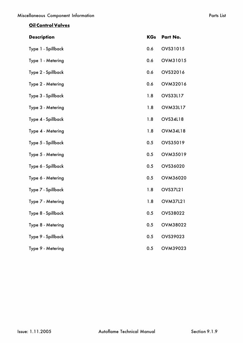
Miscellaneous Component Information
Issue: 1.11.2005 Autoflame Technical Manual Section
Oil Control Valves
Description KGs Part No.
Type 1 - Spillback 0.6 OVS31015
Type 1 - Metering 0.6 OVM31015
Type 2 - Spillback 0.6 OVS32016
Type 2 - Metering 0.6 OVM32016
Type 3 - Spillback 1.8 OVS33L17
Type 3 - Metering 1.8 OVM33L17
Type 4 - Spillback 1.8 OVS34L18
Type 4 - Metering 1.8 OVM34L18
Type 5 - Spillback 0.5 OVS35019
Type 5 - Metering 0.5 OVM35019
Type 6 - Spillback 0.5 OVS36020
Type 6 - Metering 0.5 OVM36020
Type 7 - Spillback 1.8 OVS37L21
Type 7 - Metering 1.8 OVM37L21
Type 8 - Spillback 0.5 OVS38022
Type 8 - Metering 0.5 OVM38022
Type 9 - Spillback 0.5 OVS39023
Type 9 - Metering 0.5 OVM39023
9.1.9
Parts List

Miscellaneous Component Information
Issue: 1.11.2005 Autoflame Technical Manual Section
Gas Control Valves - Screwed
Description KGs Part No.
BSP 25mm (1”) 0.55 GV42521
BSP 40mm (1.5”) 0.7 GV44022
BSP 50mm (2”) 0.74 GV45023
BSP 65mm (2.5”) 0.85 GV46524
BSP 80mm (3”) 0.98 GV48025
NPT 25mm (1”) 0.55 GV42521U
NPT 40mm (1.5”) 0.7 GV44022U
NPT 50mm (2”) 0.74 GV45023U
NPT 65mm (2.5”) 0.85 GV46524U
NPT 80mm (3”) 0.98 GV48025U
9.1.10
Parts List

Miscellaneous Component Information
Issue: 1.11.2005 Autoflame Technical Manual Section
Gas Control Valves - 30mm Flanged
Description KGs Part No.
PN16 65 mm (2.5”) 5 GVF46526/30
PN16 80 mm (3”) 6 GVF48027/30
PN16 100 mm (4”) 7 GVF410026/30
PN16 125 mm (5”) 8 GVF12527/30
PN16 150 mm (6”) 9 GVF415028/30
ANSI 150lb 65 mm (2.5”) 5 GVF46526/30U
ANSI 150lb 80 mm (3”) 6 GVF48027/30U
ANSI 150lb 100 mm (4”) 7 GVF410026/30U
ANSI 150lb 125 mm (5”) 8 GVF12527/30U
ANSI 150lb 150 mm (6”) 9 GVF415028/30U
Gas Control Valves - 50mm Flanged
Description KGs Part No.
PN16 65 mm (2.5”) 9 GVF46526/50
PN16 80 mm (3”) 10 GVF48027/50
PN16 100 mm (4”) 11 GVF410026/50
PN16 125 mm (5”) 12 GVF12527/50
PN16 150 mm (6”) 13 GVF415028/50
ANSI 150lb 65 mm (2.5”) 9 GVF46526/50U
ANSI 150lb 80 mm (3”) 10 GVF48027/50U
ANSI 150lb 100 mm (4”) 11 GVF410026/50U
ANSI 150lb 125 mm (5”) 12 GVF12527/50U
ANSI 150lb 150 mm (6”) 13 GVF415028/50U
9.1.11
Parts List

Miscellaneous Component Information
Issue: 1.11.2005 Autoflame Technical Manual Section
Sundires and Spare Parts
Description KGs Part No.
M.M./E.G.A. Technical Manual, Hard Copy 1 SP10001
M.M./E.G.A. Technical Manual, CD-ROM 0.1 SP10001/CD
Autoflame Sales Brochure 0.1 SP2000/US
Tamper Proof Screwdriver 0.07 SP10002
Transformer 230V/120V-24V 0.65 SP10003
Ferrite Core Set 0.22 SU10010
Anti Voltage Surge Module 0.15 SU10011
Cables
Description KGs Part No.
Screened Cable 1 core 0.05 CAB50001
Screened Cable 2 core 0.06 CAB50002
Screened Cable 3 core 0.07 CAB50003
Screened Cable 4 core 0.09 CAB50004
Sceened Cable 6 core 0.12 CAB50006
Screened Cable 8 core 0.14 CAB50008
Screened Cable 10 core 0.17 CAB50010
Screened Data Cable 1 pair 0.2 CAB50020
Relays
Description KGs Part No.
Relay LY2 12V DC 0.04 EC50200
Relay Base 12V 0.05 EC50201
Relay MY 240V AC 0.04 EC50206
Relay Base 240V 0.05 EC50207
9.1.12
Parts List

Miscellaneous Component Information
Issue: 1.11.2005 Autoflame Technical Manual Section
MM System Spares
Description KGs Part No.
Mk6 EPROMS, Set of 3 0.2 MK6PROMS
Mk6/Mini Mk6 MM Fuse Set, (TE5) 2A (T) 0.1 FU10034
Mk6/Mini Mk6 MM Fuse Set, (TE5) 630mA (T) 0.1 FU10028
Mini Mk5 MM Fuse Set, .315A (T) 0.1 FU10024
Mini Mk5 MM Fuse Set, 630mA (T) 0.1 FU10025
Mk6 MM Connector Plugs 0.5 CON1060
Mk6 Water Level Control Connector Plugs 0.2 CON1065
Mini Mk6 MM Connector Plugs 0.5 CON1064
Mini Mk5 MM Connector Plugs 0.5 CON1063
Mk5 MM Connector Plugs 0.5 CON1050
MM Enclosure Mounting Clamps 0.1 ENC10061
MM Water Level Enclosure and Pillars 0.2 ENC10065
UV Scanner Spares
Description KGs Part No.
Replacement Bulb + PCB for MM60003 0.1 SP1036
Replacement Bulb + PCB for MM60003/HS 0.1 SP1036HS
Replacement Bulb + PCB for MM60004/U 0.1 SP1037U
Replacement Bulb + PCB for MM60004/HSU 0.1 SP1037HSU
9.1.13
Parts List

Miscellaneous Component Information
Issue: 1.11.2005 Autoflame Technical Manual Section
EGA System Spares
Description KGs Part No.
O2 Sensor 0.02 SP10004
CO2 Sensor 0.09 SP10005
NO Sensor 0.04 SP10007
CO Sensor 0.04 SP10008
SO2 Sensor 0.01 SP10013
EGA Pump 230V 0.33 SP10009
EGA Pump 120V 0.33 SP10006
EGA Pump 24V 0.33 SP10010
EGA Replacement Internal Filter 0.06 SP10011
EGA Replacement Sampling Probe Filter 0.15 SP10012
EGA Replacement Particulate Filter 0.06 SP10018
Mk6 EGA Fuse Set 0.1 SP1040
EGA Connector Plugs 0.5 CON1010
EGA Type K Thermocouple only 0.25 SP1044
EGA Type K Thermocouple only 0.25 SP1044/5
EGA Type K Thermocouple only 0.25 SP1044/10
EGA Probe Sample Tube Set 0.01 SP10019
Mk6 EGA Spare Key 0.1 SP1045
Gas/Oil Valve Spares
Description KGs Part No.
O-ring Type 1,2,5,6,8,9 Small Oil Valve 0.01 OR70003
O-ring Type 3,4,7 Large Oil Valve 0.01 OR70004
9.1.14
Parts List

Miscellaneous Component Information
Issue: 1.11.2005 Autoflame Technical Manual Section
DTI System Spares
Description KGs Part No.
Mk6 DTI Fuse Set 0.1 SP1060
Digital I/O Fuse Set 0.1 SP1061
Analogue I/O Fuse Set 0.1 SP1062
Mk6 DTI Connector Plugs 0.5 CON1065
Digital I/O Connector Plugs 0.5 CON1066
Analogue I/O Connector Plugs 0.5 CON1067
Servomotor Spares
Description KGs Part No.
Small Servo Fixing Screws 0.01 F5015
Small Servo Mounting Bracket/Coupling 0.5 SP10015
Small Valve to Large Servo Mounting Coupling 0.5 SP10017
Large Servo Fixing Screws 0.01 F6015
Large Servo Mounting Bracket/Coupling 0.5 SP10016
Industrial Servo 05 Mounting Bracket 0.8 SP10028/05For MM10070
Industrial Servo 10 Mounting Bracket 0.8 SP10028/10For MM10072
Industrial Servo 20/40 Mounting Bracket 1 SP10028/20For MM 10074 & MM10078
Mounting Bracket for Feed Water Valve and Servo 0.8 SP10028WL/05For MM10070
Mounting Bracket for Feed Water Valve and Servo 0.8 SP10028WL/10For MM10072
9.1.15
Parts List

Miscellaneous Component Information
Issue: 1.11.2005 Autoflame Technical Manual Section
Demo/Test Equipment
Description KGs Part No.
Mk6 MM Demo Case, 230V 12 MM10022
Mk6 MM Demo Case, 120V 12 MM10023
Mini MK6 Demo Case, 230V 12 MM10030
Mini MK6 Demo Case, 120V 12 MM10030/110
DTI Demo Case, 230V 12 MM10027
DTI Demo Case, 120V 12 MM10027/110
Mk6 Protection Test Tool 0.5 MM6000TB
9.1.16
Parts List

Miscellaneous Component Information
Issue: 1.11.2005 Autoflame Technical Manual Section

Appendix
Issue: 1.11.2005 Autoflame Technical Manual Section
Section 10: Appendix
10: Index
10.1 Terms and Conditions
10.3 Patent Number Information Relevant to the System
10.4 International Type Approvals Information
10.5 Conversion Data
10.5.1 Calorific Fuel Data10.5.2 Gas Volume Conversion Factors
12345678901234567890123451234567890123456789012345123456789012345678901234512345678901234567890123451234567890123456789012345123456789012345678901234512345678901234567890123451234567890123456789012345123456789012345678901234512345678901234567890123451234567890123456789012345123456789012345678901234512345678901234567890123451234567890123456789012345

Appendix
Issue: 1.11.2005 Autoflame Technical Manual Section
10.1 Terms and Conditions
All equipment and services offered and sold by Autoflame Engineering are subject to our publishedterms and conditions of business a copy of which is supplied with each consignment of goods and acopy of which will be supplied seperately on request.
All terms and conditions are subject to English law.
10.1

Appendix
Issue: 1.11.2005 Autoflame Technical Manual Section
10.3 Patent Numbers Relevant to the System
Patent No.: Product: Applicable Country:
02138610 M.M. U.K.Australia
1317356 M.M. Canada
02169726 E.G.A. U.K.
00195866 E.G.A. Europe- U.K.SwitzerlandBelgiumFranceGermanyHollandLuxembourgSweden
GB97 15898.4 Mk6 Worldwide
PCT/GB97/02010 Mk6 Worldwide
GB97 15899.2 Mk6 U.K.
GB97 15900.8 Mk6 U.K.
6024561 UV Scanner USA
1022515 UV Scanner Europe- U.K.GermanyFranceHollandItaly
6520122 Water Level Control USASteam Flow MeteringTurbulence (pending)
1384944 Water Level Control Europe- U.K.Steam Flow Metering GermanyTurbulence France
Holland
Surface Blowdown (pending) USAUK
10.3.1

Appendix
Issue: 1.11.2005 Autoflame Technical Manual Section 10.3.2

Appendix
Issue: 1.11.2005 Autoflame Technical Manual Section 10.3.3
Appendix
Issue: 1.11.2005 Autoflame Technical Manual Section 10.3.4

Appendix
Issue: 1.11.2005 Autoflame Technical Manual Section 10.3.5

Appendix
Issue: 1.11.2005 Autoflame Technical Manual Section 10.4.1

Appendix
Issue: 1.11.2005 Autoflame Technical Manual Section 10.4.2

Appendix
Issue: 1.11.2005 Autoflame Technical Manual Section 10.4.4.1

Appendix
Issue: 1.11.2005 Autoflame Technical Manual Section 10.4.4.2

Appendix
Issue: 1.11.2005 Autoflame Technical Manual Section 10.4.4.3

Appendix
Issue: 1.11.2005 Autoflame Technical Manual Section 10.4.520.08.97

Appendix
Issue: 1.11.2005 Autoflame Technical Manual Section 10.4.6

Appendix
Issue: 1.11.2005 Autoflame Technical Manual Section 10.4.7

Appendix
Issue: 1.11.2005 Autoflame Technical Manual Section 10.4.8

Appendix
Issue: 1.11.2005 Autoflame Technical Manual Section 10.4.9

Appendix
Issue: 1.11.2005 Autoflame Technical Manual Section 10.4.10

Appendix
Issue: 1.11.2005 Autoflame Technical Manual Section
10.4.11 Additional Approvals
Approvals
10.4.11
Approval No.: Product: Applicable TypeApproval Authority:
MH25659 Mk6 Burner Management System UL, CUL, UR
0063AT5181 Mk6 Burner Management System CE
TU 12/94 0167 Mk5. M.M./E.G.A. System T.U.V. Bayern e.v.
TU 12/96 171 Mini M.M./E.G.A. System T.U.V. Bayern e.v.

Appendix
Issue: 1.11.2005 Autoflame Technical Manual Section
10.5 CONVERSION DATA
10.5 .1 Calorific Fuel Data
10.5.1
Conversion Data
Stats KeroseneSG
Gas OilCI/SH
Relative density15.6°C (60°F) approx./ = litres x = kg
0.79 0.835
Flash point (closed) min °C (°F) 37.8 (100) 65.6 (150)Viscosity kinematic (cSt) at15.6°C (60°F) approx.37.8°C (100°F) approx.82.2°C (180°F) approx.
-2.0
--
--
3.0
Equivalent Redwood No.1Viscosity at 37.8°C (100°F)
- 33 approx
Freezing point °C / °F Below -40 Below -40Cloud point °C max - -2.2Gross calorific valuesKJ/kg approx.Btu/ib approx.KWh/litre approx.Therms/gallon approx.kW/kg
46,52020,00010.181.58
-
45,59019,60010.571.64
12.66Sulphur content % wt. 0.2 0.6Water content % vol. Negligible 0.05Sediment content % wt - NegligibleAsh content % wt - NegligibleMean specific heat between0°C - 100°C approx. 0.50 0.49Volume correction factor per 1°C 0.00083 0.00083Volume correction factor per 1°F 0.00046 0.00046Btu/U.S. gallon (US standard) - 140,000Lb/U.S. gallon (US standard) - 7.01% lighter than water 20%1 u.s. Gallon of oil / ft of air 1402
Conversion Factor for Imperial Gas Flow Meters
Required Data: Pressure of gas at meter in “wgRequired gas flow in ft³/min

Appendix
Issue: 1.11.2005 Autoflame Technical Manual Section
10.5 .2 Gas Volume Conversion Factors - Measured conditions to standard reference
Assumed gas temperature 10 °C 50 °FStandard pressure 760 mmHg 101.3612 KpaStandard temperature 15.56 °CAmbient pressure 101.325 Kpa
How to use this information:-1. Measure Volumetric flow of gas for 1min in ft3 (i.e. ft3/min). Note 1m3 = 35.31ft32. Multiply this volume flow by 60 to give volumetric flow per hour (i.e. ft3/hr).3. Measure the pressure of the gas supply.4. Use the table above to obtain a conversion factor.5. Multiply the volume flow per hour by the conversion factor to obtain a volume at reference conditions.6. For natural gas, the calorific value is typically 1000 Btu/ft3. To obtain the firing rate of the boiler atstandard reference conditions multiply the volume at reference conditions by 1000.
Represented as an equation:-Firing rate = ( Measured Volumetric flow per minute * 60 * Conversion factor * 1000 ) Btu/hr
10.5.2
Conversion Data
"Wg PSI mmH2O mmHg Kpa Millibar Conversion factor1 0.036 25.4 1.867 0.249 2.490 1.02182 0.072 50.8 3.734 0.498 4.980 1.02433 0.108 76.2 5.601 0.747 7.470 1.02684 0.144 101.6 7.468 0.996 9.960 1.02935 0.181 127.0 9.335 1.245 12.451 1.03186 0.217 152.4 11.202 1.494 14.941 1.03437 0.253 177.8 13.069 1.743 17.431 1.03688 0.289 203.2 14.936 1.993 19.921 1.03939 0.325 228.6 16.804 2.242 22.411 1.0418
10 0.361 254.0 18.671 2.491 24.901 1.044315 0.542 381.0 28.006 3.736 37.352 1.056920 0.722 508.0 37.341 4.981 49.802 1.069425 0.903 635.0 46.677 6.227 62.253 1.081930 1.083 762.0 56.012 7.472 74.703 1.094435 1.264 889.0 65.347 8.717 87.154 1.107040 1.444 1016.0 74.682 9.963 99.604 1.119545 1.625 1143.0 84.018 11.208 112.055 1.132050 1.805 1270.0 93.353 12.453 124.505 1.144555 1.986 1397.0 102.688 13.699 136.956 1.157160 2.166 1524.0 112.024 14.944 149.406 1.169665 2.347 1651.0 121.359 16.189 161.857 1.182170 2.527 1778.0 130.694 17.435 174.307 1.194775 2.708 1905.0 140.030 18.680 186.758 1.207280 2.889 2032.0 149.365 19.925 199.208 1.219785 3.069 2159.0 158.700 21.171 211.659 1.232290 3.250 2286.0 168.035 22.416 224.109 1.244895 3.430 2413.0 177.371 23.661 236.560 1.2573100 3.611 2540.0 186.706 24.907 249.010 1.2698110 3.972 2794.0 205.377 27.397 273.911 1.2949120 4.333 3048.0 224.047 29.888 298.812 1.3199130 4.694 3302.0 242.718 32.379 323.713 1.3450140 5.055 3556.0 261.388 34.869 348.614 1.3700150 5.416 3810.0 280.059 37.360 373.515 1.3951160 5.777 4064.0 298.730 39.851 398.416 1.4201170 6.138 4318.0 317.400 42.341 423.317 1.4452180 6.499 4572.0 336.071 44.832 448.218 1.4703190 6.860 4826.0 354.741 47.323 473.119 1.4953200 7.221 5080.0 373.412 49.813 498.020 1.5204

Appendix
Issue: 1.11.2005 Autoflame Technical Manual Section