ncsx engineering design document design description field
TRANSCRIPT

NCSX Engineering Design Document Design Description Field Period Assembly (WBS 18)
NCSX PDR October 7-9, 2003 Lead Author: Mike Cole

NCSX Engineering Design Document Field Period Assembly
ii
Table of Contents 1 Introduction .........................................................................................................................................................1 2 DESIGN REQUIREMENTS AND CONSTRAINTS.......................................................................................1 2.1 Primary Functions..............................................................................................................................................1 2.2 Facility Description and Constraints..................................................................................................................2 3 ASSEMBLY STEPS AND SEQUENCE............................................................................................................5 3.1 Vacuum Vessel Assembly .................................................................................................................................5
3.1.1 Magnetic loops / saddle coils.....................................................................................................................5 3.1.2 Cooling / heating trace lines ......................................................................................................................6 3.1.3 Thermal insulation .....................................................................................................................................6 3.1.4 Vessel support hardware............................................................................................................................7
3.2 Assembly of the Modular Coils .........................................................................................................................7 3.3 Vacuum Vessel Support Hardware..................................................................................................................10 3.4 Assembly of the TF Coils ................................................................................................................................10 3.5 Assembly of External Trim Coils ....................................................................................................................13 3.6 Assembly of the Ports......................................................................................................................................15 3.7 Vacuum Vessel Final Support Adjustment......................................................................................................15 4 COST AND SCHEDULE..................................................................................................................................16 4.1 Cost..................................................................................................................................................................16 4.2 Schedule ..........................................................................................................................................................17
List of Figures Figure 1 Complete Stellarator Core Field Period 1 Figure 2 PPPL Site Plan 2 Figure 3 TFTR Test Cell 3 Figure 4 TFTR Crane 3 Figure 5 TFTR Loading Station 4 Figure 6 Vacuum Vessel Support 5 Figure 7 Cooling / heating line tracing installed on vacuum vessel 6 Figure 8 Vacuum Vessel thermal insulation 6 Figure 9 Modular Coil Subassembly with fixture 7 Figure 10 Modular coil subassembly on fixture for assembly over vacuum vessel 8 Figure 11 Load transfer fixture 9 Figure 12 Modular coil load transfer fixture 9 Figure 13 Vacuum vessel support hardware 10 Figure 14 TF coil half-field period subassembly 11

NCSX Engineering Design Document Field Period Assembly
iii
Figure 15 Assembly sequence of TF half-field period subassembly 12 Figure 16 TF Coil installation support fixture 13 Figure 17 External trim coils 13 Figure 18 Field period with trim coils installed 14 Figure 19 External trim coil array 14 Figure 20 Typical Vacuum Vessel Port Extension ready for welding 15 Figure 21 Field period assembly with trim coils 16 Figure 22 Field period assembly schedule 18
List of Tables Table 1 Crane capacities 2 Table 2 Typical components to be lifted and weights 4 Table 3 WBS structure for Stellarator Core Assembly 16 Table 4 Costs for field period assembly ($k without contingency) 17 Table 5 Budget by year for field period assembly 17

NCSX Engineering Design Document Field Period Assembly
1
1 INTRODUCTION
The National Compact Stellarator Experiment (NCSX) is an experimental research facility that is to be constructed at the Department of Energy’s Princeton Plasma Physics Laboratory (PPPL). Its mission is to acquire the physics knowledge needed to evaluate compact stellarators as a fusion concept, and to advance the understanding of 3D plasma physics for fusion and basic science.
A primary component of the facility is the stellarator core, an assembly of four magnet systems that surround a highly shaped plasma and vacuum chamber. The coils provide the magnetic field required for plasma shaping and position control, inductive current drive, and error field correction.
This document describes the requirements, design concept, and cost of activities associated with the assembly of a stellarator core field period.
2 DESIGN REQUIREMENTS AND CONSTRAINTS
2.1 Primary Functions
The Field Period Assembly includes all the design, tooling, equipment, materials and labor required to prepare for assembly and to assemble one field period of the stellarator core. A complete field period is illustrated in Figure 1. Activities include receipt and inspection of the various components, preparation for assembly, assembly, inspection, and testing. The primary components include the vacuum vessel, modular coils, TF coils, coil structure, and external trim coils.
TF Coils
Modular Coils
Ext Trim Coils
Vacuum Vessel Ports
TF Coils
Modular Coils
Ext Trim Coils
Vacuum Vessel Ports
Figure 1 Complete Stellarator Core Field Period

NCSX Engineering Design Document Field Period Assembly
2
2.2 Facility Description and Constraints
The TFTR Test Cell has been identified as the area to be used for the assembly of the Field Periods. The field period assembly operation will share this area with the modular coil winding operation. An overall view of the site is shown in Figure 2.
Figure 2 PPPL Site Plan
The TFTR test cell, shown in Figure 3, is approximately 114 ft wide by 150 ft. long. The modular coil area will occupy the North side of the building. The Field Period Assembly will be located around the modular coil area in the east and south side of the building. PPPL will coordinate the cleanup and installation of fixtures that will be used for Field Period Assembly. Utilities such as instrument air, power and data ports will be installed or upgraded based on the needs of each fixture, but at the present time the utilities appear adequate. Data ports will be installed as needed, primarily to collect the metrology data that will be generated during the assembly processes. The building crane will be shared with the modular coil assembly. The crane capabilities are shown Table 1 and Figure 4.
Table 1 Crane capacities
Description Capacity
Crane Capacity 110 Ton Big Hook
25 Ton Small Hook (micro control)
Hook Height 42’ main hook motorized rotation small hook freely rotates height 42 ft plus

NCSX Engineering Design Document Field Period Assembly
3
Figure 3 TFTR Test Cell
Figure 4 TFTR Crane

NCSX Engineering Design Document Field Period Assembly
4
The Field Period Assembly area will make use of the crane primarily for picking up major components such as the Vacuum Vessel, Modular Coil, TF Coil and the completed Field Period Assembly. When components arrive from the vendor they will be inspected for damage, lifted off the truck and placed in an area designated for receiving inspection. All necessary documentation will be reviewed and any additional testing will be performed. When the component has passed the receiving inspection test it will be lifted to the appropriate fixture in the assembly area.
When a Field Period Assembly is completed it will be lifted from the fixture in the assembly area and set on a truck for shipment as shown in Figure 5. The Field Period Assembly will be driven a short distance on site to the NCSX test cell.
The crane is not expected to be used for day-to-day assembly. Local fixtures will be used for assembly. Typical lifts and the weights are shown in Table 2. After a lift has been performed the crane will be released for other operations needed in the TFTR Test Cell.
Figure 5 TFTR Loading Station
Table 2 Typical components to be lifted and weights
Description Weight
Vacuum Vessel 6,400 lbs
M1 Coil 7,100 lbs
M2 Coil 6,700 lbs
M3 Coil 7,100 lbs
Half period Modular Coil 21,000 lbs x 2
Half period TF Coil 11,000 lbs x 2
Field Period Assembly 70,400 lbs

NCSX Engineering Design Document Field Period Assembly
5
3 ASSEMBLY STEPS AND SEQUENCE
3.1 Vacuum Vessel Assembly
The Field Period Assembly will begin with the assembly of the vacuum vessel. The vacuum vessel will be assembled to the vacuum vessel support fixture, as shown in Figure 6. The lower vertical port flange is bolted to the mating flange on the vacuum vessel support fixture. A column located in the center of the vessel will supply stability during the assembly.
Figure 6 Vacuum Vessel Support
The following components will be assembled to the outside of the vessel.
3.1.1 Magnetic loops / saddle coils
The Field Period Assembly plan is to install 130 magnetic loops and/or saddle coils on the first period. If the magnetic analysis indicates the need for more coils these coils will be added to the second and third period assembly. The plan today is to install saddle coils on the first period and add additional coils if needed.
The technique for installing the saddle coils is to place a template over the surface of the vacuum vessel. The template will have holes to mark the location on the vessel where studs will be attached.. The mineral insulated (MI) cable for the sensors will be wrapped around the studs on the vessel. Leads from the coils will be routed to the vertical ports and terminated in a junction box on the ports. The MI cable will be held in place by wrapping the cable with thin tabs and spot welded to the vessel.
Measurements of the coils will be made using a Faro arm or laser tracker and recorded for future information. The measurement tolerance for locating these coils is +- .030.

NCSX Engineering Design Document Field Period Assembly
6
3.1.2 Cooling / heating trace lines
Cooling/heating trace lines will be added to each period as shown in Figure 7. These cooling/heating tubes will be attached to the vessel by stud welding “J” clamps to the vessel. A 1/16-inch gap is designed between the vessel and the cooling tubes. This gap provides clearance for the installation of the saddle coils.
Stycast, a thermally conducting epoxy, will be placed between the vessel and tubes. A total of 32 tubes will be attached to the outside surface. The location of the tubes is not as critical as previous components. The cooling tubes are 0.375” O.D. x .035” wall thickness and made of Inconel 600 and will be preformed before assembly.
Figure 7 Cooling / heating line tracing installed on vacuum vessel
3.1.3 Thermal insulation
Microtherm and solimide polymide foam, one half inch thick each, will be added to the outside of the vacuum vessel surface as shown in Figure 8. The insulation will be cut from sheets and wrapped around the outside vessel surface. The method of holding the insulation in place has not been decided.
Figure 8 Vacuum Vessel thermal insulation

NCSX Engineering Design Document Field Period Assembly
7
3.1.4 Vessel support hardware
The next step would be to install the vacuum vessel support hardware that suspends the vessel from the modular coil shell. This hardware cannot be installed at this time because of the limited clearance during the assembly of the modular coils over the vacuum vessel The installation of the vacuum vessel support hardware will be discussed after the installation of the shell.
3.2 Assembly of the Modular Coils
The assembly of the modular coils will consist of four steps. Step 1 is to review the dimensional inspection information generated during the manufacture of each coil. Step 2 is to assemble coil segments M1, M2 and M3 together to form the half period coil subassembly, using shims as required to obtain the best relational fit between the three coils. Step 3 is to dimensionally inspect the coil sub-assemblies. Step 4 is to assemble the left and right half period sub assemblies over the vacuum vessel.
Step 1
Inspection data from each coil will be collected, including the relationship between the winding geometry, flange geometry, and tooling ball monuments. The location of these features relative to the global machine assembly will be calculated based on the optimum position of each coil in the assembly. This information must be processed to determine the best fit of the coils in the final assembly, and to size the shims needed for the next step.
Step 2
The modular coils will first be assembled into segments consisting of the three coils using the fixture shown in Figure 9. This procedure will start with M1. The M1 coil segment will be placed in the fixture and measured to verify location. A shim, which has been sized based on dimensional data taken during the fabrication of the M1 coil and the next coil segment, M2, will be placed on the flange. The M2 segment will be lowered into place and insulated bolts will be matched reamed with the flange holes. The bolt and nut assembly will be torqued to specification. Dimensional inspection data will be taken to verify the location of the coil. The M3 coil will be assembled next using the same procedure as done for the M2 coil. After the three shell segments have been assembled, cryolite batt insulation will be placed between the windings.
Step 3
After the 3-coil subassembly is completed, it must be re-inspected. The purpose of this inspection is to verify the assembly of the half period coil subassembly and to compare this information with a second half period assembly to size the shim needed at the Field Period Assembly.
Figure 9 Modular Coil Subassembly with fixture
NCSX Engineering Design Document Field Period Assembly
8
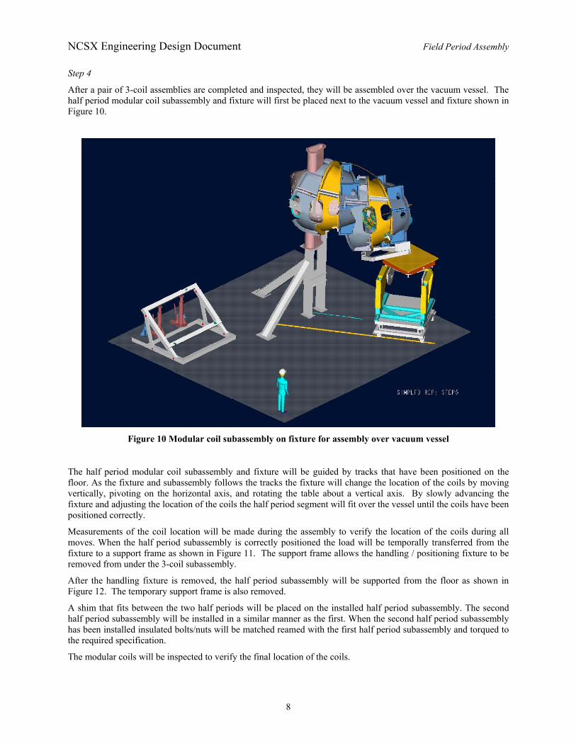
Step 4
After a pair of 3-coil assemblies are completed and inspected, they will be assembled over the vacuum vessel. The half period modular coil subassembly and fixture will first be placed next to the vacuum vessel and fixture shown in Figure 10.
Figure 10 Modular coil subassembly on fixture for assembly over vacuum vessel
The half period modular coil subassembly and fixture will be guided by tracks that have been positioned on the floor. As the fixture and subassembly follows the tracks the fixture will change the location of the coils by moving vertically, pivoting on the horizontal axis, and rotating the table about a vertical axis. By slowly advancing the fixture and adjusting the location of the coils the half period segment will fit over the vessel until the coils have been positioned correctly.
Measurements of the coil location will be made during the assembly to verify the location of the coils during all moves. When the half period subassembly is correctly positioned the load will be temporally transferred from the fixture to a support frame as shown in Figure 11. The support frame allows the handling / positioning fixture to be removed from under the 3-coil subassembly.
After the handling fixture is removed, the half period subassembly will be supported from the floor as shown in Figure 12. The temporary support frame is also removed.
A shim that fits between the two half periods will be placed on the installed half period subassembly. The second half period subassembly will be installed in a similar manner as the first. When the second half period subassembly has been installed insulated bolts/nuts will be matched reamed with the first half period subassembly and torqued to the required specification.
The modular coils will be inspected to verify the final location of the coils.

NCSX Engineering Design Document Field Period Assembly
9
Figure 11 Load transfer fixture
Figure 12 Modular coil load transfer fixture

NCSX Engineering Design Document Field Period Assembly
10
3.3 Vacuum Vessel Support Hardware
The vacuum vessel support hardware can now be installed between the vacuum vessel and the shell. A clevis subassembly will be fitted thru access ports in the shell and screwed into bosses that are in the vessel, as shown in Figure 13. Threaded rod can be inserted into the clevis from the outside of the shell. Belleville washers and a nut will be attached to the threaded rod and tightened against the shell until the vacuum vessel is snug. The vessel will not be fully supported by this hardware until the ports have been installed and welded to the vessel.
Figure 13 Vacuum vessel support hardware
3.4 Assembly of the TF Coils
The completed half period TF coil subassembly is shown in Figure 14. The subassembly consists of 3 TF coils with a cast top and bottom support structure. The assembly of the TF coil subassembly is shown in Figure 15. This subassembly step is required prior to assembling the TF coils over the modular coil shell. The TF coils will be positioned slightly offset in the radial direction (~1/4 in) from their final position. This provides clearance during the final machine assembly, when the three Field Periods are installed on the base structure.
The assembly trajectory of the TF Coil half period subassembly is much simpler than the modular coil assembly. The TF Coil half period subassembly can be simply rotated over the modular coils. The fixtures for the assembly are shown in Figure 16.
Before the TF Coil can be assembled, the supports for the Modular Coils must be positioned to allow free access over the Modular Coil. One end of the modular coils is supported from the ground. This allows the opposite half shell subassembly to be cantilevered from the fixed half shell subassembly. With no supports preventing the installation of the TF Coil half period the coils are simply rotated into position. Shims are sized and then placed between the TF Coil and the Modular coils. The two sub-assemblies are then bolted together. Supports are then placed under the TF Coil support and the procedure is repeated for the opposite side.

NCSX Engineering Design Document Field Period Assembly
11
TF Coils
Upper Casting Assembly
Lower Casting Assembly
Figure 14 TF coil half-field period subassembly

NCSX Engineering Design Document Field Period Assembly
12
TF Coil Windings
Lower Inner Support Casting
TF Coil Windings
Lower Outer Casting
TF Coil Windings
Lower Casting Sub Assembly Coil Positioning
Support
TF Coil Windings
Lower Casting Sub Assembly
Upper Inner Casting Support
TF Coil Windings
Lower Casting Sub Assembly
Upper Casting Support Connectors
TF Coil Windings
Lower Casting Sub Assembly
Upper Outer Casting Support
Figure 15 Assembly sequence of TF half-field period subassembly

NCSX Engineering Design Document Field Period Assembly
13
Existing PF ring coil supports
I-beams support outer TF structure
TF structure inner support
column Final support locations that will attach to modular
coil shell
Existing PF ring coil supports
I-beams support outer TF structure
TF structure inner support
column Final support locations that will attach to modular
coil shell
Figure 16 TF Coil installation support fixture
3.5 Assembly of External Trim Coils
After the assembly of the TF coils, the External Trim Coils will be attached to the Field Period Assembly. The External Trim Coils are shown in Figure 17. The external trim coils consist of three upper, three lower, and two outer coils. The upper and lower coils are attached to the frame of the TF coil support structure. The outer trim coil is mounted on the outside of the TF coil (Figure 18). At the machine assembly level an additional outer trim coil will be added between each Field Period Assembly. The complete assembly of all the external trim coils is shown in Figure 19.
3 Upper Trim Coils
3 Lower Trim Coils
One Outer Trim Coil
3 Upper Trim Coils
3 Lower Trim Coils
One Outer Trim Coil
Figure 17 External trim coils

NCSX Engineering Design Document Field Period Assembly
14
TF Coils
Modular Coils
Ext Trim Coils
TF Coils
Modular Coils
Ext Trim Coils
Figure 18 Field period with trim coils installed
Upper Trim Coils
Lower Trim Coils
Outer Trim Coils
Upper Trim Coils
Lower Trim Coils
Outer Trim Coils
Figure 19 External trim coil array

NCSX Engineering Design Document Field Period Assembly
15
3.6 Assembly of the Ports
The vacuum vessel ports are the last major items to be assembled to the Field Period Assembly. Before installing the ports the Field Period Assembly will have the components assembled as shown in Figure 18. A typical port configuration is shown in Figure 20. A backing ring is shown welded to the port. The backing ring will help position the port over the stub in the vacuum vessel (Figure 20). An assembly fixture will be used to maintain alignment of the ports relative to the global reference frame. All of the ports will be positioned on the vessel and aligned using the alignment fixture. As each port is positioned a tack weld will hold the port stable. After all ports have been assembled each joint will be finished with a full penetration weld. Blank off flanges will be installed on the ports and on the open ends of the vacuum vessel. The vacuum vessel will be baked above the normal bake out temperature (150oC) to 165oC and cycled several times. A vacuum leak test will be performed to verify all the welds are leak tight. In addition to the vacuum leak test, a dimensional verification of the port locations will be performed. All fixtures shall be removed and the inspection shall be made with the ports in a “free condition”.
Weld Backing Ring Figure 20 Typical Vacuum Vessel Port Extension ready for welding
3.7 Vacuum Vessel Final Support Adjustment.
Before completing the Field Period Assembly, the vacuum vessel has to be supported from the shell. The support hardware that was installed after the modular coils is now tightened until the vessel is barely lifted off the support fixture. The vessel is now free and can move inside the shell assembly. Temporary blocking will be installed between the shell and the vessel during transport from the assembly area to the NCSX test cell. The completed field period assembly is shown in Figure 21.

NCSX Engineering Design Document Field Period Assembly
16
TF Coils
Modular Coils
Ext Trim Coils
Vacuum Vessel Ports
TF Coils
Modular Coils
Ext Trim Coils
Vacuum Vessel Ports
Figure 21 Field period assembly with trim coils
4 COST AND SCHEDULE
4.1 Cost
The costs for the stellarator core assembly were developed as a bottoms up estimate using estimated times and crew sizes and recent experience assembling the NSTX device. The WBS structure and costs are summarized in Table 3 and Table 4. Some cost savings have been realized by using standard equipment where possible, such as the standard weld positioner, lifting table, and metrology equipment. The total cost of $5036k is divided among the categories of oversight ($1371k), inspection and assembly activities ($1782k), and tooling/fixtures/metrology equipment ($1883k). The overall contingency is 32% for this element, which apportions 40% to both field period assembly and tooling and fixtures.
Table 3 WBS structure for Stellarator Core Assembly
WBS Description
Stellarator Core Systems18 Field Period Assembly
181 Planning and Oversight182 Preparation of the TFTR Test Cell183 Receipt, Inspection, and Testing of Coils184 Receipt, Inspection, and Testing of Vacuum Vessel185 Field Period Assembly186 Tooling Design and Fabrication187 Measurement Systems

NCSX Engineering Design Document Field Period Assembly
17
Table 4 Costs for field period assembly ($k without contingency)
Sum of cost WBS
Cost CategoryExpense class 181 182 183 184 185 186 187 Grand Total
2) Title I & II Labor/Other $490 $51 $541
M&S $158 $158
3) Fabrication/Assembly (incl title III) Labor/Other $1,371 $77 $288 $1,325 $17 $10 $3,089
M&S $423 $439 $862
3) Fabrication/Assembly (incl title III) Total $1,371 $77 $288 $1,325 $440 $450 $3,951
4) Installation/Test Labor/Other $91 $244 $49 $385
4) Installation/Test Total $91 $244 $49 $385
Grand Total $1,371 $91 $77 $288 $1,325 $1,333 $550 $5,036
4.2 Schedule
The schedule shown in Figure 22 represents the durations of each task arranged in a continuous assembly process. The actual schedule depends on deliveries of the various components and is given in the Project Master Schedule. The cost spread over the schedule is shown in Table 5.
Table 5 Budget by year for field period assembly
WBS Level 2 FY03 FY04 FY05 FY06 FY07 TOTAL($k) ($k) ($k) ($k) ($k) ($k)
18 - Field Period Assembly $88 $964 $1,287 $2,631 $66 $5,036
The duration of 179 days shown is the same as defined in the master schedule. This schedule shows the maximum length of time it would take to assemble a period if all operations were performed in a sequential pattern. Looking at the schedule in this way provides some insight into tasks that may be performed at an earlier time or identify tasks that can be done in parallel that could decrease the time required to fabricate the field period assembly. In reviewing the schedule it is clear that an early delivery of the vacuum vessel would allow operations such as installing magnetic loops, installing cooling/heating tubes and insulation to begin as soon as the vessel is delivered. Performing operations in parallel such as assembling the half period Modular Coils and half period TF Coils would also decrease the total field period assembly. Several task cannot be adjusted as the assembly depends on the preceding task being completed first. The schedule is always under review to determine options that may have been overlooked or modifications that might be made to decrease the assembly time.

NCSX Engineering Design Document Field Period Assembly
18
Figure 22 Field period assembly schedule